

Pitney Bowes DM100i Series, DM200i Series Service Manual & Parts List
DM100i/DM200i series
Mailing System
Service Manual & Parts List
FORM SDT345A (8-07)

IMPORTANT:
Model and feature availability varies by country. Contact your machine supplier for more information.
This guide covers all models and features. Inclusion within this guide does not guarantee availability of a
particular model or feature within your country.
The title, copyright and all other proprietary rights in this document are vested in Pitney Bowes Limited and no part of it may be reproduced
in any form without the written permission of Pitney Bowes Limited.
The document is for the exclusive use of the person to whom it is issued; its contents are condential and must not be disclosed to any
third party or used for any purpose other than in the proper conduct of Pitney Bowes Limited's business and it must be returned to Pitney
Bowes Limited immediately upon the person ceasing to be associated with Pitney Bowes Limited.
© Pitney Bowes Limited, 2007

Page
Service Manual
SECTION 1
Introduction
1.1 - Purpose ............................................................................................ 1-1
1.2 - Equipment Covered .......................................................................... 1-1
1.3 - Contents ........................................................................................... 1-1
1.4 - Safety Summary ............................................................................... 1-1
1.5 - Equipment Safety ............................................................................. 1-2
SECTION 2
Specications
2.1 - Material Specication ........................................................................ 2-1
2.2 - Machine Specication ....................................................................... 2-2
SECTION 3
Removal & Replacement
3.1 - External Covers ................................................................................ 3-1
3.2 - Carriage Unit Related ....................................................................... 3-4
3.3 - Purge Unit Related ............................................................................ 3-9
3.4 - Lower Delivery Unit Related .............................................................. 3-12
3.5 - PCBs ................................................................................................. 3-18
• Contents
• Contents
SECTION 4
Troubleshooting
4.1 - Introduction ....................................................................................... 4-1
4.2 - Troubleshooting Tables ..................................................................... 4-1
Parts List
SECTION 5
Parts List ........................................................................................................... 5-1
SDT345A DM100i Series Service Manual & Parts List
i

• Contents
ii SDT345A DM100i Series Service Manual & Parts List

1.1 PURPOSE
This document provides the information necessary to support the installation and site repair of the
DM100i/DM200i Series Digital Mailing System.
1.2 EQUIPMENT COVERED
This manual applies to the DM100i/DM200i Series and the kits required for digital mailing system
operation.
1.3 CONTENTS
This manual is organised as follows:
● Section 1 – Introduces the manual
● Section 2 – Lists material and equipment specications
● Section 3 – Presents removal and replacement procedures
● Section 4 – Offers Troubleshooting advice.
● Section 5 – Provides a full parts list.
1.4 SAFETY SUMMARY
Warning messages are used throughout this manual to alert you to potentially hazardous conditions.
These warnings are explained below.
Introduction • 1
1 • Introduction
WARNING — calls attention to improper practices that could cause injury.
●
● CAUTION — calls attention to improper practices that could damage the equipment or the material
being run.
● IMPORTANT — calls attention to practices that could adversely affect equipment operation, if
instructions are not followed exactly.
You must familiarise yourself with proper procedures and methods before you install, operate or service
the equipment to avoid personal injury or damage to the equipment. If you are responsible for training
service personnel or equipment operators, it is incumbent on you to explain safety precautions to your
students and encourage safety awareness.
The following is a list of general precautions which cannot be over emphasised:
● HIGH VOLTAGE is present at certain points in the equipment. INJURY or DEATH could result if
you fail to observe safety precautions.
● Know how to turn off power in the work area and how to summon help in case of emergency.
● Do not work on equipment under power unless absolutely necessary.
● When working on a live circuit, use extreme caution. Don’t grasp two sides of a live circuit at the
same time.
● Always use the right tools for the job.
● Treat every circuit like a gun which may be loaded. It may not be “live”, but be sure. Check with a
neon tester, a voltmeter, or simply unplug the machine.
SDT345A DM100i/DM200i Series Service Manual & Parts List
1-1

1 • Introduction
● Use one hand when reaching into a circuit. By keeping one hand free, lethal current is less likely
to pass through vital organs. Observe this rule when connecting or disconnecting plugs or leads,
and when making any adjustments on a live circuit. Don’t underestimate the danger of shock: 1mA
(1/1000 ampere) is uncomfortable; 5 mA (1/200 ampere) is dangerous - the victim may jump back
and be injured; 12 mA (1/83 ampere) causes hand muscles to contract - the victim cannot free
himself; 24 mA (1/40 ampere) has proven fatal; and 100 mA (1/10 ampere) is likely to be fatal.
● Don’t reach into a circuit with metal tools, or while wearing rings or a watch. Even in low voltage
circuits, a metal object can short circuit two terminals.
● Don’t bypass safety devices. Three-wire outlets (220/240 VAC) are designed to ground equipment
to make it safe. If a live wire shorts to a grounded frame, the only result is an open fuse. If a live
wire shorts to an ungrounded frame, the frame itself becomes hot and potentially dangerous. A
fuse is a weak link in a circuit, designed to break down before anything else does. The maximum
safe current in a circuit is determined by the designers. Too large a fuse can pass excessive current, damaging expensive equipment. Interlock switches are designed to remove power from a
circuit when an access door, cover or panel is opened. When such a switch is “cheated” or otherwise disabled, a safety device has been bypassed. If you bypass an interlock for service or
diagnostic purposes, use extreme caution.
● If you use air pressure to clean a machine, use low pressure (30 psi or less) and use eye protec-
tion (goggles or face masks).
● When using solvents or cleaning uids, make sure ventilation is adequate.
1.5 EQUIPMENT SAFETY
Just by walking around, you yourself may carry a threat to the equipment, in the form of a high voltage
electrostatic charge. Your body acts as a giant capacitor which can store large amounts of electricity.
Walking across a rug can charge you with several thousand volts, which can discharge in a spark up
to an inch long.
Digital equipment can be easily damaged or destroyed by static charges. Microprocessors and other
ICs contain tiny transistors not much more than a millionth of an inch across, which operate at 5 to
12 volts. You don’t have to see a spark to ruin an IC — 50 volts is enough. Follow these guidelines to
protect sensitive equipment from static damage:
● Ground yourself before reaching into the equipment, or touching any circuit board or other electrical
component. Just touching a doorknob or metal workbench may be enough, but the best guarantee
is to turn the machine off but leave it plugged in, and ground yourself on the chassis, which is
grounded through the three-wire power cord. If you have access to one, bring a grounding strap
and use it.
● Be careful of rugs — even a few steps can recharge you. Re-ground yourself whenever you’ve
walked away and returned to the machine. Rugs are a major source of static buildup in the
body.
1-2 SDT345A DM100i/DM200i Series Service Manual & Parts List

Introduction • 1
WARNING!
Always be sure the equipment is unplugged before you make any attempt
to perform the maintenance outlined in this manual. If you must work on a
"live" machine, note that line potential is present at the power panel and the
motherboard.
CAUTION: DO NOT attempt to adjust key timing parameters in the service menu
unless you have been trained and thoroughly understand what you're doing.
Otherwise you could damage the equipment.
● Take greater precautions as the objects you handle get smaller. A board in the machine is better
protected than one which is not plugged in; a chip on a board is better protected than one in your
hand.
● Stay away from metal conductors. The plastic and resin that chips and boards are made of are
much better insulators than metal. It’s most important to keep your hands away from any metal
which contacts the data. In particular, this means the long connector along the bottom of each
board, and the pins coming out of the chips. These signal and data lines are directly connected to
the fragile inner circuits of the chips. When handling a board, try not to touch the connector; when
handling a chip, try not to touch the pins.
SDT345A DM100i/DM200i Series Service Manual & Parts List
1-3

1 • Introduction
1-4 SDT345A DM100i/DM200i Series Service Manual & Parts List
2.1 MATERIAL SPECIFICATIONS
Material Specications
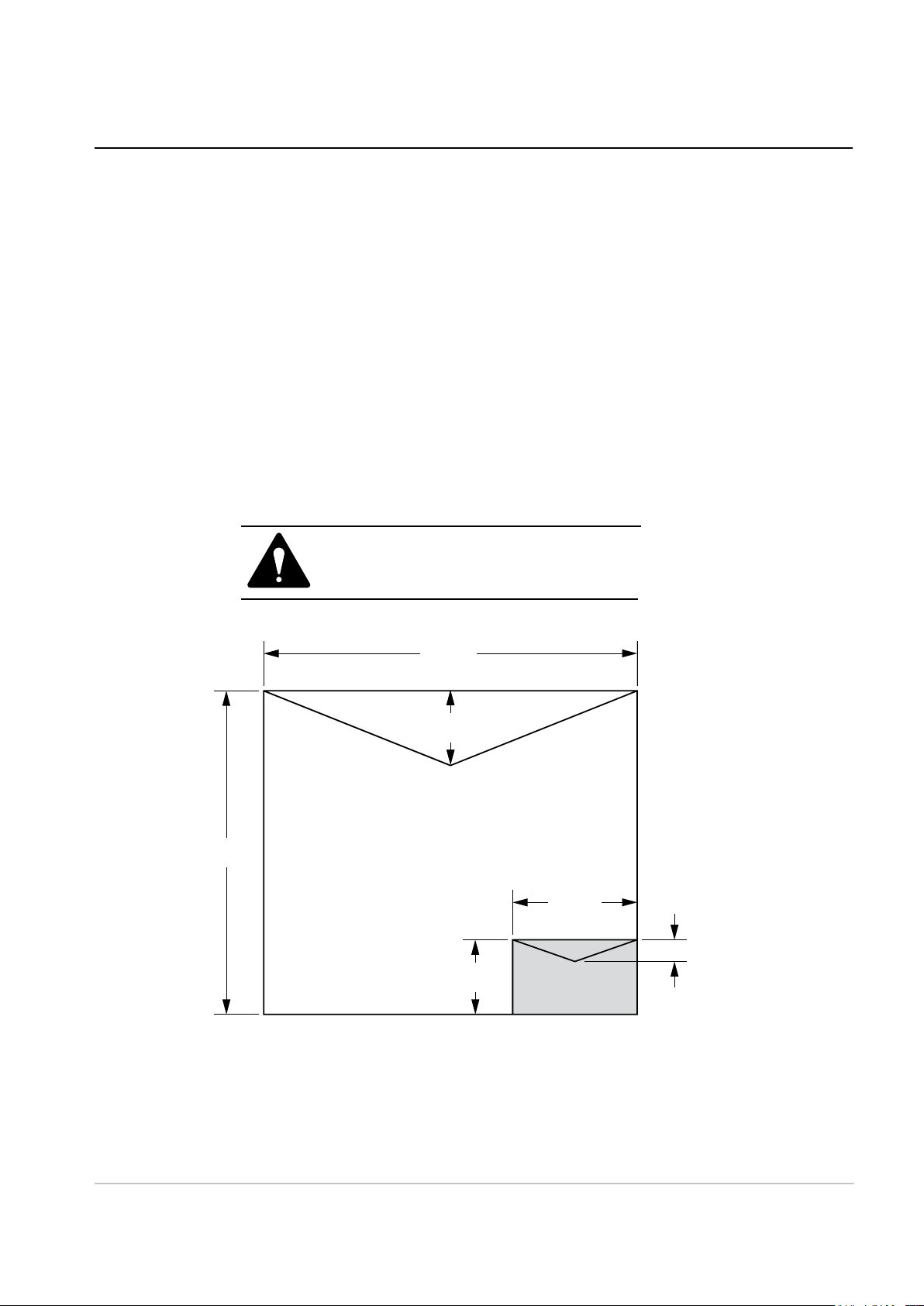
Material (see figure below)
Minimum Size: 127 mm x 76 mm
Maximum Size: 381 x 330 mm
Minimum Flap Depth: 22 mm
Maximum Flap Depth: 76 mm
Minimum Thickness: 0.18 mm
Maximum Thickness: 9.5 mm
Maximum Stack Height for Mail: 60 mm
IMPORTANT: For best results, always make
sure your material conforms to our published
specications.
2 • Specifications
2 • Specifications
330mm
381mm
76mm
Maximum
76mm
127mm
22mm
Minimum
SDT345A DM100i/DM200i Series Service Manual & Parts List
2-1

2 • Specifications
2.2 MACHINE SPECIFICATIONS
Size of Base Model:
215mm H x 345mm W x 400mm D
Size of Base Model with Scale:
230mm H x 345mm W x 400mm D
Size of Base Model with Scale and Moistener:
230mm H x 470mm W x 400mm D
Stacker:
The stacker adds 265mm to the width of the system.
Weight:
6.8Kg, approximate.
Power Requirements:
100-240 VAC, 50/60Hz. 1.0A
Communication Ports:
1 USB (B); 1 RJ-11.
Operating Temperature:
4°C to 42°C.
LCD Display: 4 Lines, 20 characters long.
Throughput: Up to 30 letters per minute with no moistener; somewhat less with optional moistener.
Actual throughput will vary depedning on the material used, machine condition, use of moistener,
and the skill of the operator.
Print Resolution: 600 x 300 dpi
Print Image Area: at least 25.4mm x 170mm
Ink Cartridge Life: 2,500 imprints or 22 letters per day, 5 days a week for 6 months.
Tape Sheets: Self-adhesive type, dual tape sheets.
Internal Ad Storage; up to 20.
Departmental Accounting: Number of accounts available based on the amount purchased and
model.
Compliance It is certied that the digital mailing systen machine complies with the
requirements of the Low Voltage Directive 73/23/EEC and the EMC
Directive 89/336/EEC. The product was tested in a typical conguration.
For a formal Declaration of Conformity please contact Compliance
Engineering on +44 (0)1279 426731.
WARNING: This is a class A product. In a domestic environment this product may cause radio
interference in which case the user may be required to take adequate measures.
2-2 SDT345A DM100i/DM200i Series Service Manual & Parts List
3 • Removal & Replacement
[1]
[1]
[1]
[2]
[1]
[2]
[3]
[4]
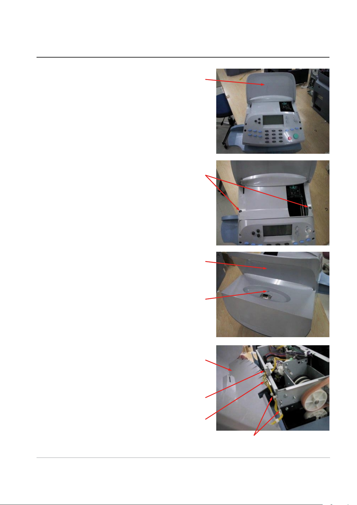
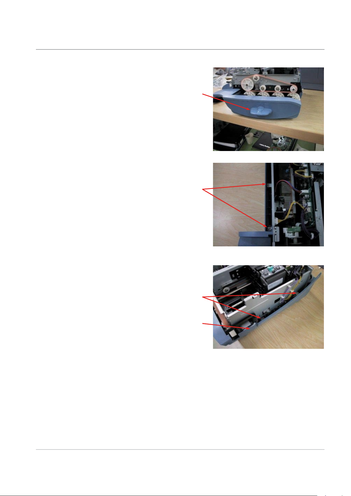
3.0 External Covers
3.0.0 Removing the Upper Cover Unit
1) Open the open/closed cover [1].
2) Remove the 2 screws [1].
3 • Removal & Replacement
3) Remove the screw [1], and detach the
upper cover unit [2].
4) Free the harness [2] from the 2 harness guides
[1]. Disconnect the connector [3] on the left side
of the main body. Remove the upper cover unit [4].
SDT345A DM100i/DM200i Series Service Manual & Parts List
3-1
3 • Removal & Replacement
[1]
[1]
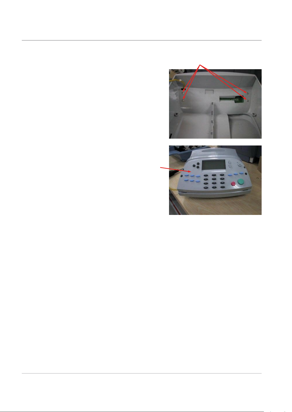
3.0.1 Removing the Control Panel Unit
1) Remove the upper cover unit. (See A-1 Removing
the Upper Cover Unit)
2) Remove the 4 screws [1].
3) Remove the control panel unit [1].
3-2 SDT345A DM100i/DM200i Series Service Manual & Parts List
[1]
[1]
[1]
[2]
3.0.2 Removing the Lower Cover Unit
1) Remove the upper cover unit. (See A-1 Removing
the Upper Cover Unit)
2) Pull out the lever [1].
3) Remove the 2 screws [1] on the left side of the
main body.
3 • Removal & Replacement
4) Remove the 2 screws [1] on the right side of the
main body, and detach the lower cover unit [2].
SDT345A DM100i/DM200i Series Service Manual & Parts List
3-3
3 • Removal & Replacement
[1]
[2]
[1]
[1]
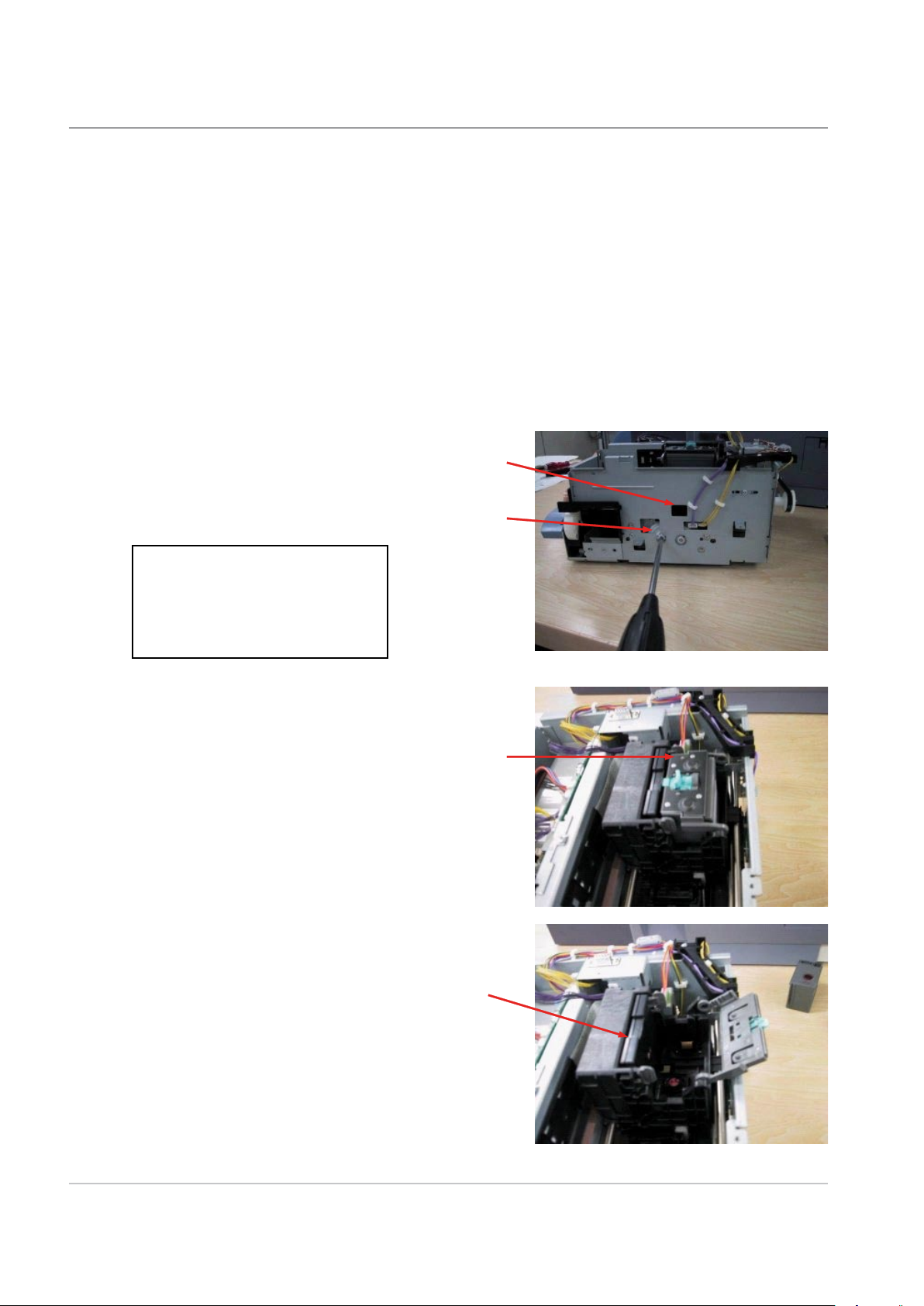
3.1 Carriage Unit Related
3.1.0 Removing the Carriage Unit
Carriage unit consists of the carriage, the guide rail of
the carriage and the carriage motor.
1) Remove the upper cover unit. (See A-1
Removing the Upper Cover Unit)
2) Remove the lower cover unit. (See A-3
Removing the Lower Cover Unit)
3) Turn the gear [1] clockwise with using a
screwdriver, to uncap the print head. The cap
can be seen from the window [2].
Caution-
Never move the carriage being
capped to prevent the print
head and the cap from damage.
4) Open the ink tank exchange cover, and
remove the ink tank.
5) Remove the print head [1].
3-4 SDT345A DM100i/DM200i Series Service Manual & Parts List
[1]
[2]
[3]
[1]
[2]
[1]
[1]
[2]
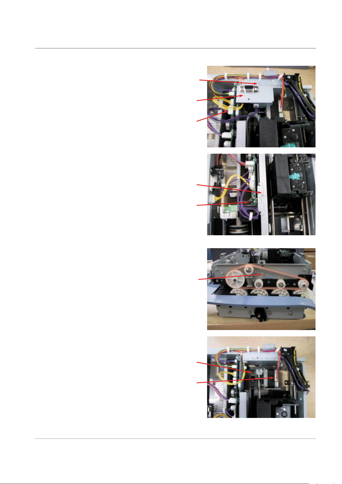
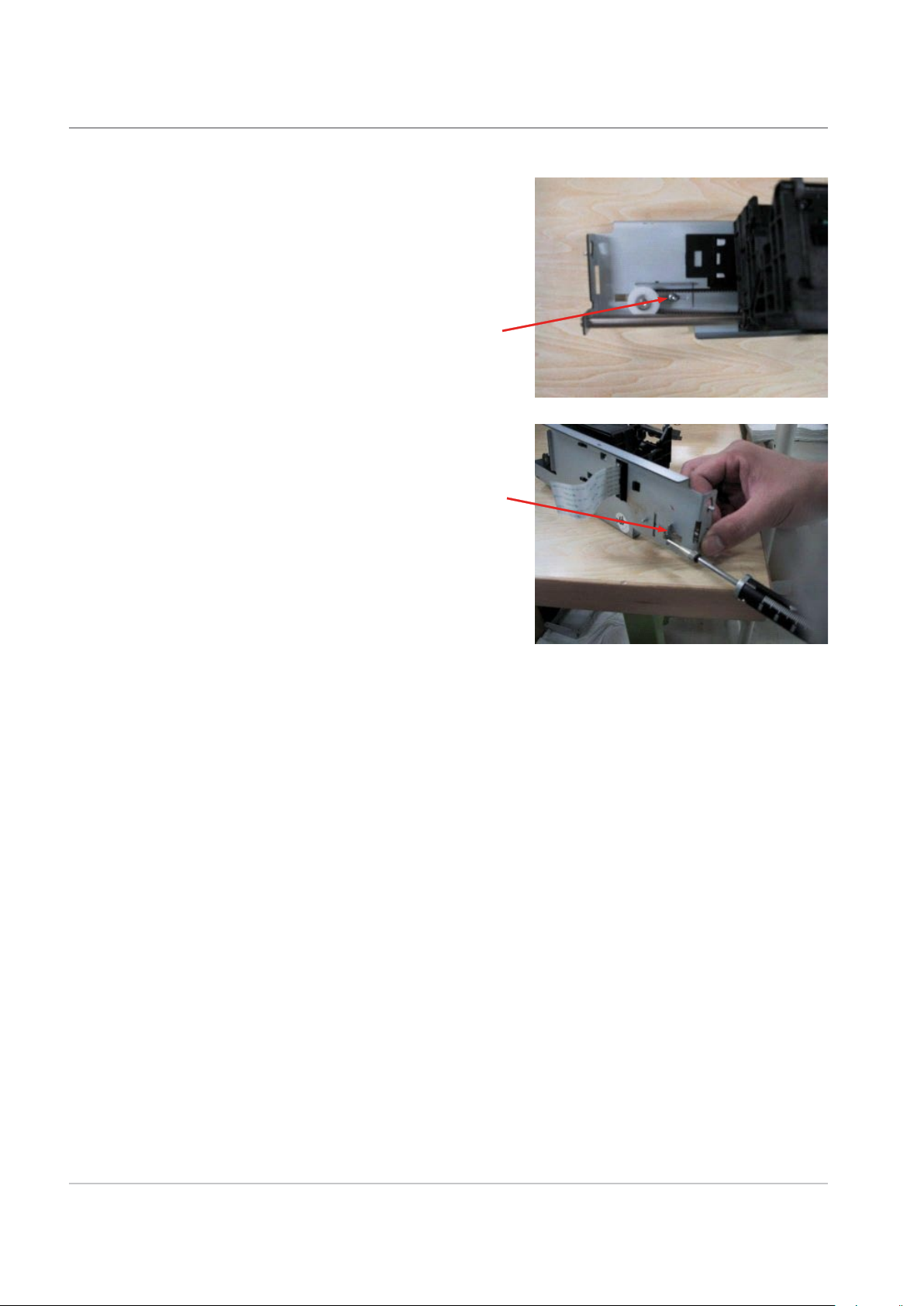
6) Disconnect the connector [1]. Remove the
screw [2] and detach the interface connector
unit [3].
7) Remove the screw [1]. Unlock the flexible
cable connector and detach the flexible cable
[2].
3 • Removal & Replacement
8) Remove the screw [1].
9) Disconnect the connector [1], and remove
the screw [2].
SDT345A DM100i/DM200i Series Service Manual & Parts List
3-5
3 • Removal & Replacement
[1]
[2]
[1]
[2]
10) Slide the carriage [1] to the front, then
move the carriage unit [2] to the rear side,
and remove the carriage unit [2].
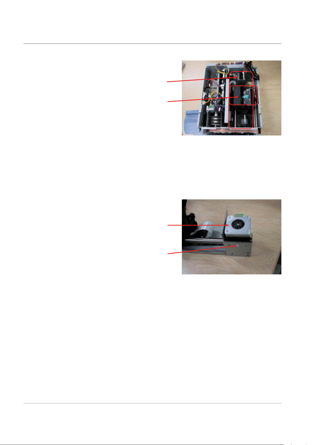
3.1.1 Removing the Carriage Drive Motor
1) Remove the carriage unit. (See B-1
Removing the Carriage Unit)
2) Remove the screw [1] and detach the
carriage drive motor [2].
3-6 SDT345A DM100i/DM200i Series Service Manual & Parts List

[1]
[2]
[1]
[2]
[1]
[1]
3.1.2 Removing the Head Holder Unit
1) Remove the carriage drive motor. (See
B-2 Removing the Carriage Drive Motor)
2) Remove the screw [1], and detach the
carriage drive rail [2].
3) Unlock the hook [1] of the flexible cable
cover.
3 • Removal & Replacement
4) Slide the flexible cable cover [1] to the left
side, and detach it. Remove the head holder
unit [2].
Caution
Do not loosen the tensioner
screw [1] of tension adjustment
for the carriage drive belt must
be made.
SDT345A DM100i/DM200i Series Service Manual & Parts List
3-7
3 • Removal & Replacement
[1]
[1]
3.1.3 Adjustment at installation of the carriage
drive belt
The tension adjustment of the belt is necessary after the
carriage drive belt is exchanged.
1) Loosen the screw [1].
2) Adjust belt tension at the hook [1] so that
the tension falls in the tolerance.
Tolerance: 1 kg±10%
3-8 SDT345A DM100i/DM200i Series Service Manual & Parts List
[1]
[2]
[1]
[1]
3.2 Purge Unit Related
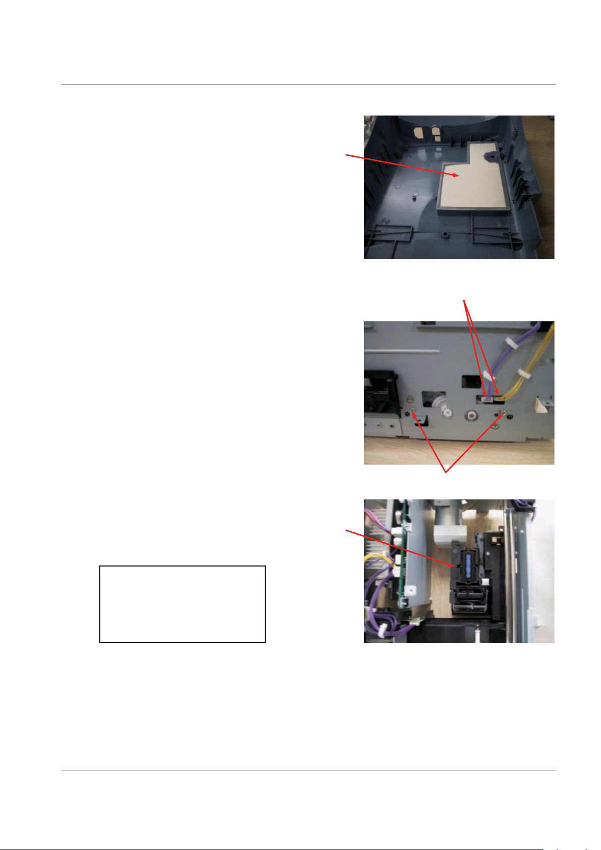
3.2.0 Removing the Waste Ink Tank Unit
Waste ink tank unit consists of the ink tank case and the ink
absorption sheet.
1) Remove the lower cover unit. (See A-3
Removing the Lower Cover Unit)
2) Remove the waste ink tank unit.
3.2.1 Removing the Purge Unit
1) Remove the carriage unit. (See B-1 Removing
the Carriage Unit)
3 • Removal & Replacement
2) Disconnect the 2 connectors [1], and remove the
2 screws [2].
3) Remove the purge unit [1].
Caution
Never touch the cap and the
wiper blade.
SDT345A DM100i/DM200i Series Service Manual & Parts List
3-9
3 • Removal & Replacement
[1]
[2]
[1]
[3]
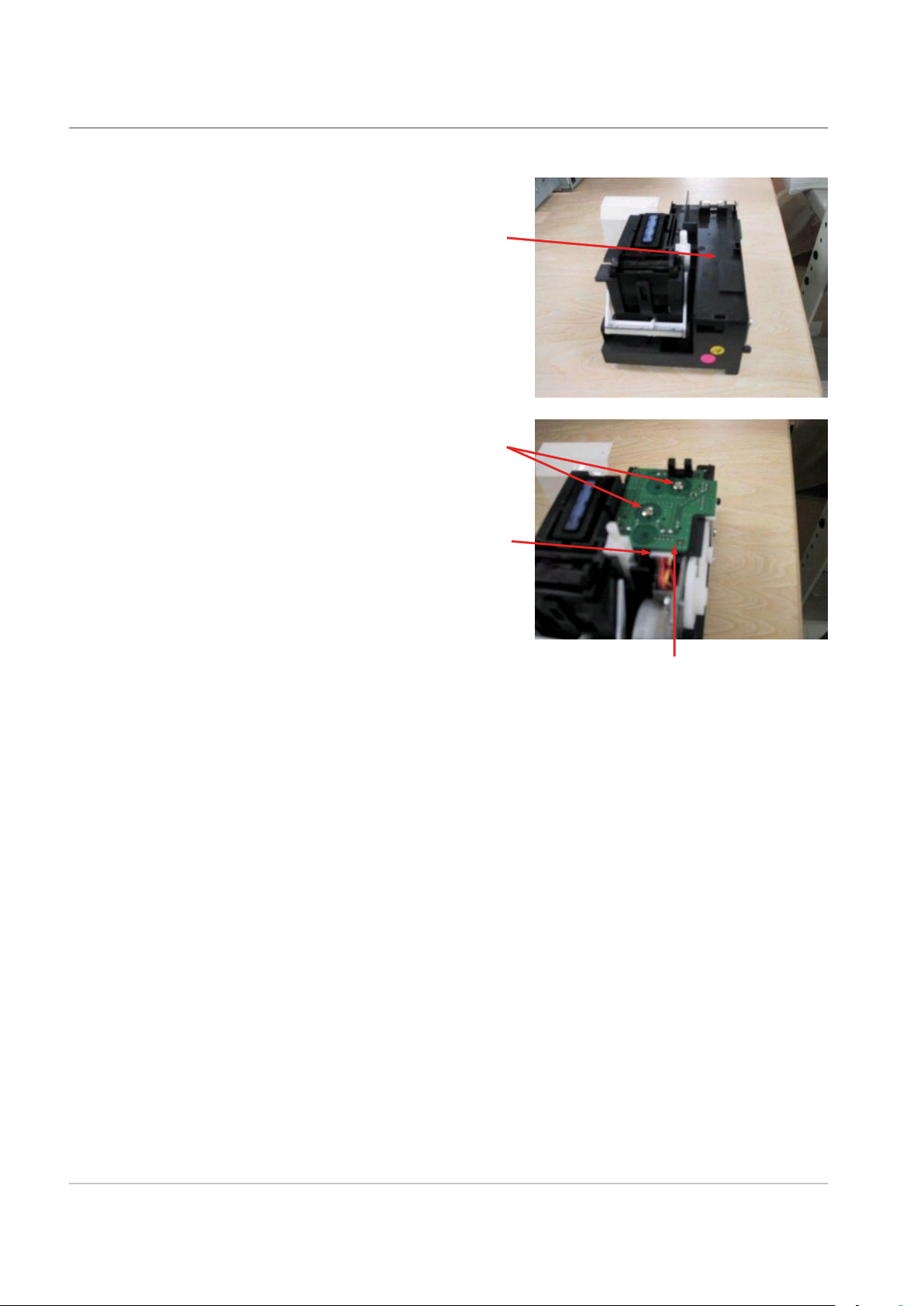
3.2.2 Removing the sensor PCB (1)
1) Remove the purge unit. (See C-2 Removing the
Purge Unit)
2) Remove the 2 hooks, and detach the cover [1].
3) Remove the 2 screws [1], connector [2], and
detach the sensor PCB (1) [3].
3-10 SDT345A DM100i/DM200i Series Service Manual & Parts List
 Loading...