

Pioneer XV-BD122B, XV-BD422B, XV-BD122FSB Service Manual
PIONEER CORPORATION 1-1, Shin-ogura, Saiwai-ku, Kawasaki-shi, Kanagawa 212-0031, Japan
PIONEER ELECTRONICS (USA) INC. P.O. Box 1760, Long Beach, CA 90801-1760, U.S.A.
PIONEER EUROPE NV Haven 1087, Keetberglaan 1, 9120 Melsele, Belgium
PIONEER ELECTRONICS ASIACENTRE PTE. LTD. 253 Alexandra Road, #04-01, Singapore 159936
PIONEER CORPORATION
2012
XV-BD422B
Blu-ray Disc receiver
XV-BD422B
XV-BD122B
XV-BD122FSB
THIS MANUAL IS APPLICABLE TO THE FOLLOWING MODEL(S) AND TYPE(S).
ORDER NO.
RRV4334
Model T ype Power Requirement
XV-BD422B YXE8 AC 110 V to 240 V 2 B &&&&######YY YY: Europe
XV-BD422B VXE8 AC 110 V to 240 V 2 B &&&&######GB GB: U.K
XV-BD122B YXE8 AC 110 V to 240 V 2 B &&&&######YY YY: Europe
XV-BD122B VXE8 AC 110 V to 240 V 2 B &&&&######GB GB: U.K
XV-BD122FSB YXE8 AC 110 V to 240 V 2 B &&&&######YY YY: Europe
DVD
Region No.BDRegion No.
Serial No. Remarks
K-MZV JULY
2012 Printed in Japan
1
LASER DIODE CHARACTERISTICS
For BD Wave length : 398 - 412 nm
Output Power : Less than Class 1
For DVD Wave length : 650 - 664 nm
Output Power : Less than Class 1
For CD Wave length : 784 - 796 nm
Output Power : Less than Class 1
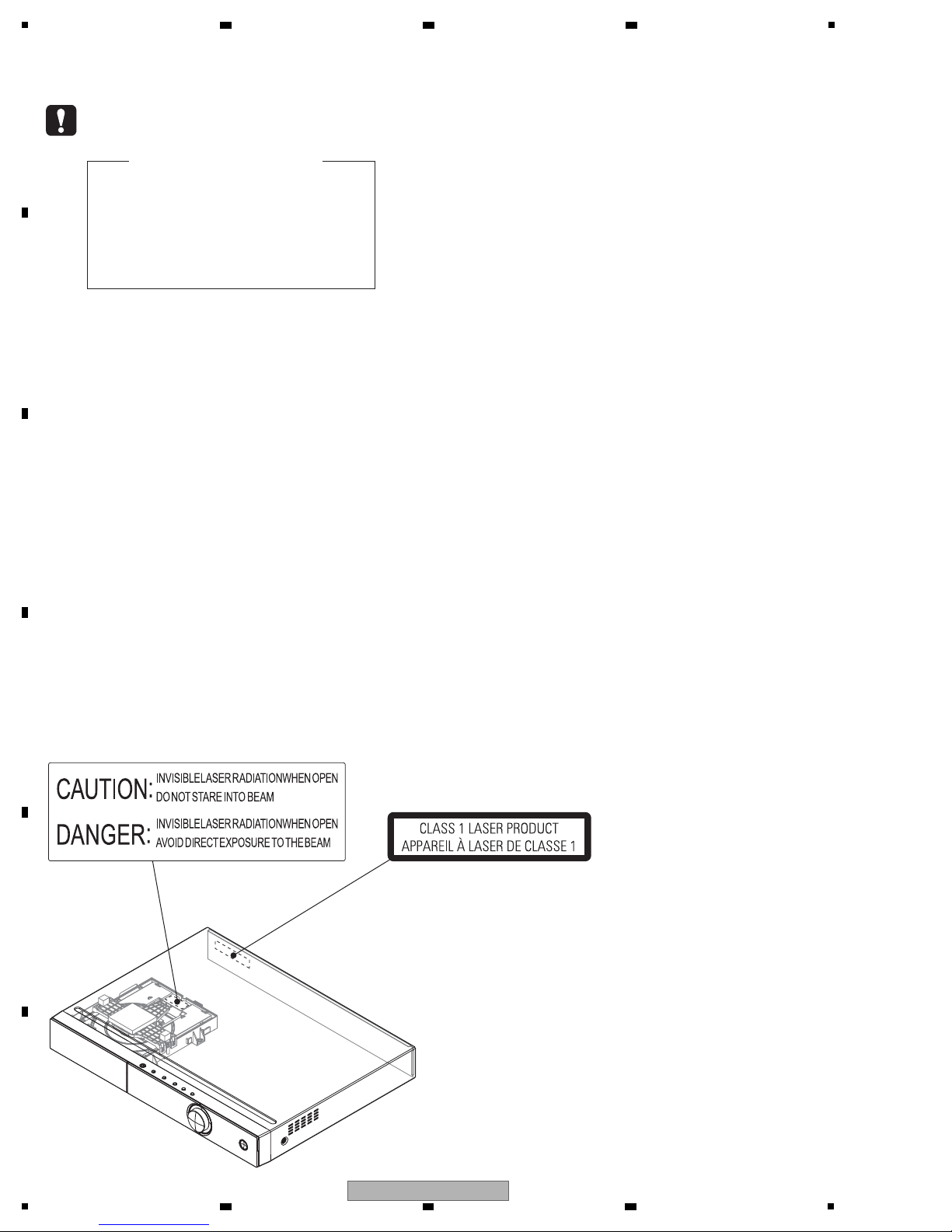
LABEL CHECK
The following caution appears on your unit.
Location: inside of the unit
(Printed on the rear panel)
SAFETY INFORMATION
A
B
2 3 4
C
D
E
F
2
1
XV-BD422B
2 3 4

5
6 7 8
CONTENTS
SAFETY INFORMATION .........................................................................................................................................................2
1. SERVICE PRECAUTIONS...................................... ..... ...... ...... ............................................ ...... ...........................................4
1.1 NOTES ON SOLDERING.................................................................. .............................................................................4
2. SPECIFICA TIO NS....................... ..... ...... ............................................. ..... ...... ...... ..... ...... ......................................................5
3. BASIC ITEMS FOR SERVICE..............................................................................................................................................6
3.1 CHECK POINTS AFTER SERVICING...........................................................................................................................6
3.2 JIGS LIST.......................................................................................................................................................................6
3.3 PCB LOCATIONS...........................................................................................................................................................7
4. BLOCK DIAGRAM ........................... ............................................. ...... ..... ...... ...... ..... ............................................................8
4.1 OVERALL WIRING DIAGRAM.......................................................................................................................................8
4.2 OVERALL BLOCK DIAGRAM......................................................................................................................................10
5. DIAGNOSIS .................... ...... ...... ..... ............................................. ...... ..... ...... ...... ..... ..........................................................12
5.1 TROUBLESHOOTING..................................................................................................................................................12
6. SERVICE MODE................................................................ ............................................. ....................................................15
6.1 SERVICE MODE..........................................................................................................................................................15
7. DISASSEMBLY ............................................................ ...... ...... ..... ...... ..... ...........................................................................21
8. EACH SETTING AND ADJUSTMENT................................................................................................................................28
8.1 ADJUSTMENT REQUIRED WHEN THE UNIT IS REPAIRED OR REPLACED.................................. ..... ...... ...... ..... ..28
8.2 UPDATING OF THE FIRMWARE.................................................................................................................................30
9. EXPLODED VIEWS AND PARTS LIST ..............................................................................................................................32
9.1 PACKING SECTION.....................................................................................................................................................32
9.2 EXTERIOR SECTION..................................................................................................................................................34
10. SCHEMATIC DIAGRAM....................................................................................................................................................38
10.1 MAIN BOARD ASSY (1/13)........................................................................................................................................38
10.2 MAIN BOARD ASSY (2/13)........................................................................................................................................40
10.3 MAIN BOARD ASSY (3/13)........................................................................................................................................42
10.4 MAIN BOARD ASSY (4/13)........................................................................................................................................44
10.5 MAIN BOARD ASSY (5/13)........................................................................................................................................46
10.6 MAIN BOARD ASSY (6/13)........................................................................................................................................48
10.7 MAIN BOARD ASSY (7/13)........................................................................................................................................50
10.8 MAIN BOARD ASSY (8/13)........................................................................................................................................52
10.9 MAIN BOARD ASSY (9/13)........................................................................................................................................54
10.10 MAIN BOARD ASSY (10/13)....................................................................................................................................56
10.11 MAIN BOARD ASSY (11/13).....................................................................................................................................58
10.12 MAIN BOARD ASSY (12/13)....................................................................................................................................60
10.13 MAIN BOARD ASSY (13/13)....................................................................................................................................62
10.14 FRONT BOARD ASSY.............................................................................................................................................64
10.15 AMP BOARD ASSY (1/3).........................................................................................................................................66
10.16 AMP BOARD ASSY (2/3).........................................................................................................................................68
10.17 AMP BOARD ASSY (3/3).........................................................................................................................................70
10.18 AV BOARD ASSY.....................................................................................................................................................72
10.19 SYSTEM POWER SUPPLY ASSY...........................................................................................................................74
11. PCB CONNECTION DIAGRAM........................................................................................................................................76
11.1 MAIN BOARD ASSY...................................................................................................................................................76
11.2 FRONT BOARD ASSY...............................................................................................................................................80
11.3 AMP and AV BOARD ASSYS.....................................................................................................................................82
11.4 SYSTEM POWER SUPPLY ASSY.............................................................................................................................84
A
B
C
D
5
XV-BD422B
6 7 8
E
F
3

1
• For environmental protection, lead-free solder is used on the printed circuit boards mounted in this unit.
Be sure to use lead-free solder and a soldering iron that can meet specifications for use with lead-free solders for repairs
accompanied by reworking of soldering.
• Compared with conventional eutectic solders, lead-free solders have higher melting points, by approximately 40 ºC.
Therefore, for lead-free soldering, the tip temperature of a soldering iron must be set to around 373 ºC in general, although
the temperature depends on the heat capacity of the PC board on which reworking is required and the weight of the tip of
the soldering iron.
Do NOT use a soldering iron whose tip temperature cannot be controlled.
Compared with eutectic solders, lead-free solders have higher bond strengths but slower wetting times and higher melting
temperatures (hard to melt/easy to harden).
The following lead-free solders are available as service parts:
• Parts numbers of lead-free solder:
GYP1006 1.0 in dia.
GYP1007 0.6 in dia.
GYP1008 0.3 in dia.
2 3 4
1. SERVICE PRECAUTIONS
1.1 NOTES ON SOLDERING
A
B
C
D
E
F
4
1
XV-BD422B
2 3 4
5
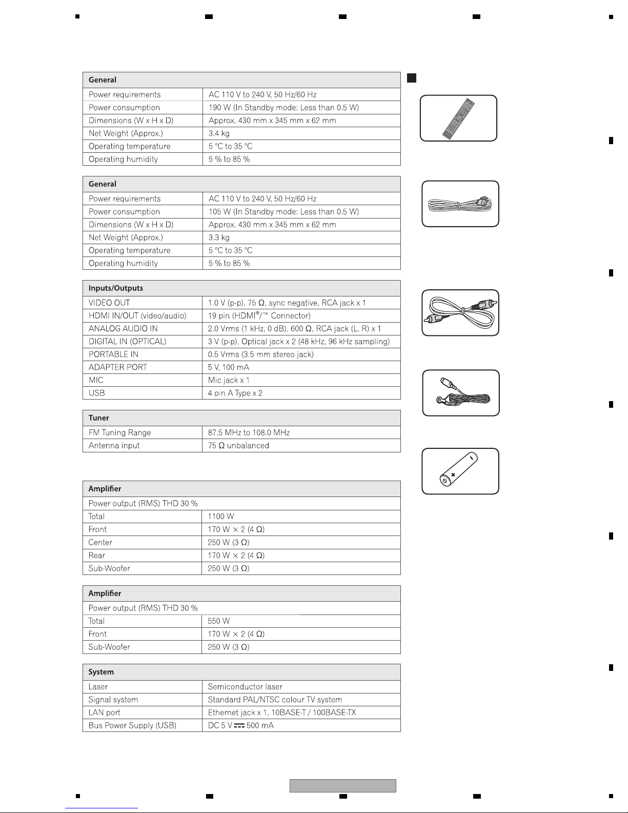
Video cable
(41-UH1200-0KK1E)
Power cord
(XV-BD422B/YXE8, XV-BD122B/YXE8,
XV-BD122FSB/YXE8: 51-DC0120-0CRA3)
(XV-BD422B/VXE8, XV-BD122B/VXE8
: 51-DC0120-0CRD4)
• Warranty card
• Operating instructions
(XV-BD422B/YXE8, XV-BD122B/YXE8,
XV-BD122FSB/YXE8: 72-BD122B-EU0B1)
(XV-BD422B/VXE8, XV-BD122B/VXE8:
72-BD122B-GBRB1)
Remote control (AXD7655)
(06-BCS727-A000)
Battery (x2)
FM antenna
(47-ANT022-XX0)
Accessories
(XV-BD422B/XV-BD122B)
(XV-BD422B/XV-BD122B)
(XV-BD122FSB)
(XV-BD122FSB)
2. SPECIFICATIONS
6 7 8
A
B
C
D
E
F
5
XV-BD422B
6 7 8
5
1
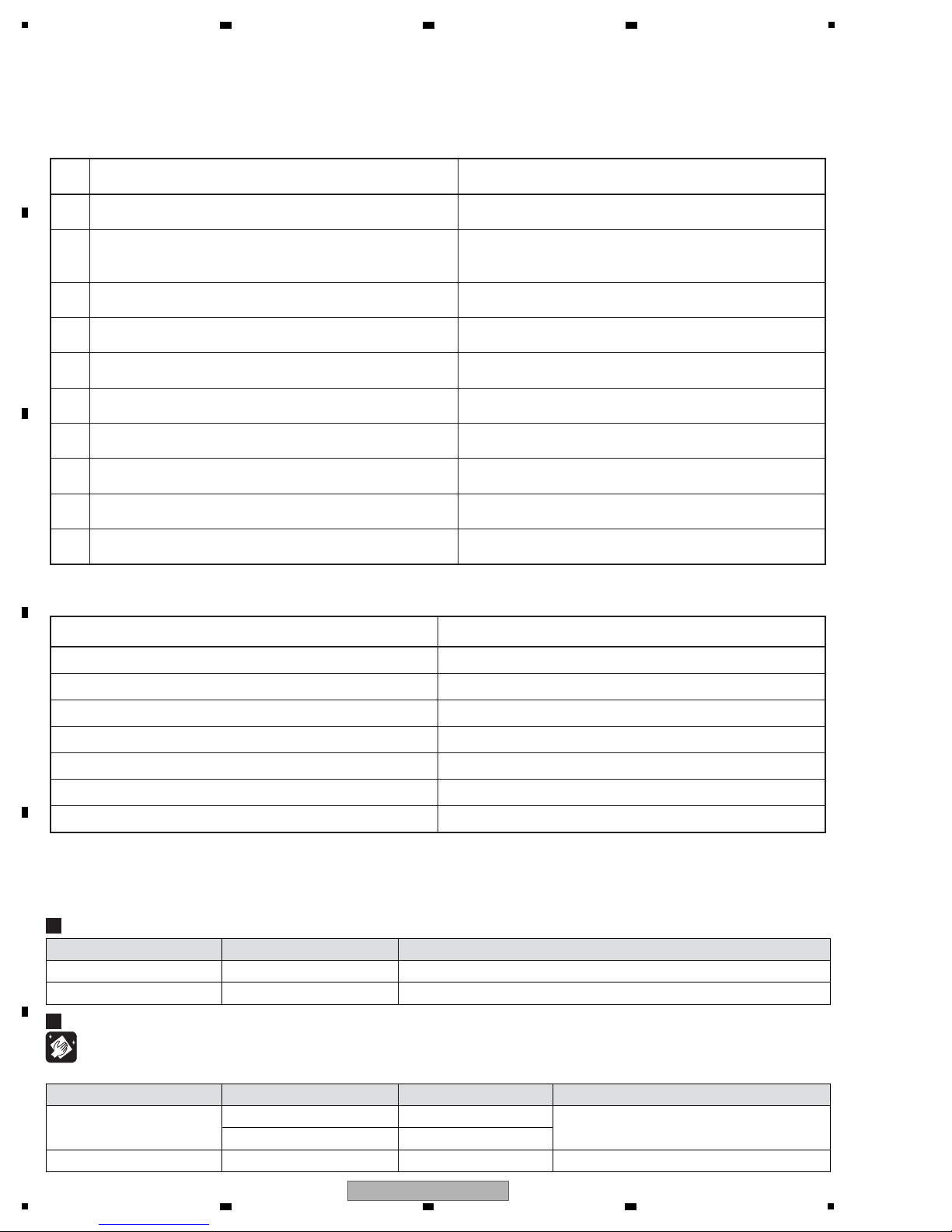
Items to be checked after servicing
To keep the product quality after servicing, confirm recommended check points shown below.
Item to be checked regarding video Item to be checked regarding audio
Block noise Distortion
Horizontal noise Noise
Dot noise Volume too low
Disturbed image (video jumpiness)
Too dark
Too bright
Mottled color
Volume too high
Volume fluctuating
Sound interrupted
See the table below for the items to be checked regarding video and audio.
1
Confirm the firmware version on Service mode.
The version of the firmware must be latest.
Update firmware to the latest one, if it is not the latest.
2
Confirm whether the customer complain has been solved.
If the customer complain occurs with the specific disc, use
it for the operation check.
The customer complain must not be reappeared.
Video, audio and operations must be normal.
3
Check the CD playback.
(Track search)
Audio and operations (search etc.) must be normal.
4
Check the DVD playback.
(Operation, Title/Chapter search)
Video, audio and operations (search etc.) must be normal.
5
Check the BD playback.
(Operation, Title/Chapter search)
Video, audio and operations (search etc.) must be normal.
6
Check the tuner (FM) operations.
Video, audio and operations (search etc.) must be normal.
10
Check the appearance of the product. No scratches or dirt on its appearance after receiving it
for service.
No. Procedure Check points
7 Check supported file playback by USB memory. Video, audio and operations must be normal.
9 Select [Scan] on [Wireless Setting] and then check access
points are displayed on screen. (*)
(*) Wireless model only (XV-BD121W/122W/222W/421W/422W/921FSW/922FSW/821FSW/ 822FSW/621FSW/521FSW)
Correct access point name (SSID) must be displayed. (*)
8 Check supported file playback from same network device by
LAN connection at Home MEDIA GALLERY .
Video, audio and operations must be normal.
Cleaning
Name Part No. Remarks
Cleaning paper GED-008
Cleaning liquied GEM1004 Refer to "7. DISASSEMBLY".
Position to be cleaned
Pickup lenses
Cleaning paper GED-008 Refer to "9.2 EXTERIOR SECTION".Fan
Before shipping out the product, be sure to clean the following positions by using the prescribed cleaning tools.
Jig Name Part No. Remarks
BD Test disc GGV1368 Use with "6. SERVICE MODE".
Emergency disc ejection rod
GGF1529 Refer to "7. DISASSEMBLY".
Jigs List
2 3 4
3. BASIC ITEMS FOR SERVICE
3.1 CHECK POINTS AFTER SERVICING
A
B
C
D
3.2 JIGS LIST
E
F
6
1
2 3 4
XV-BD422B
5
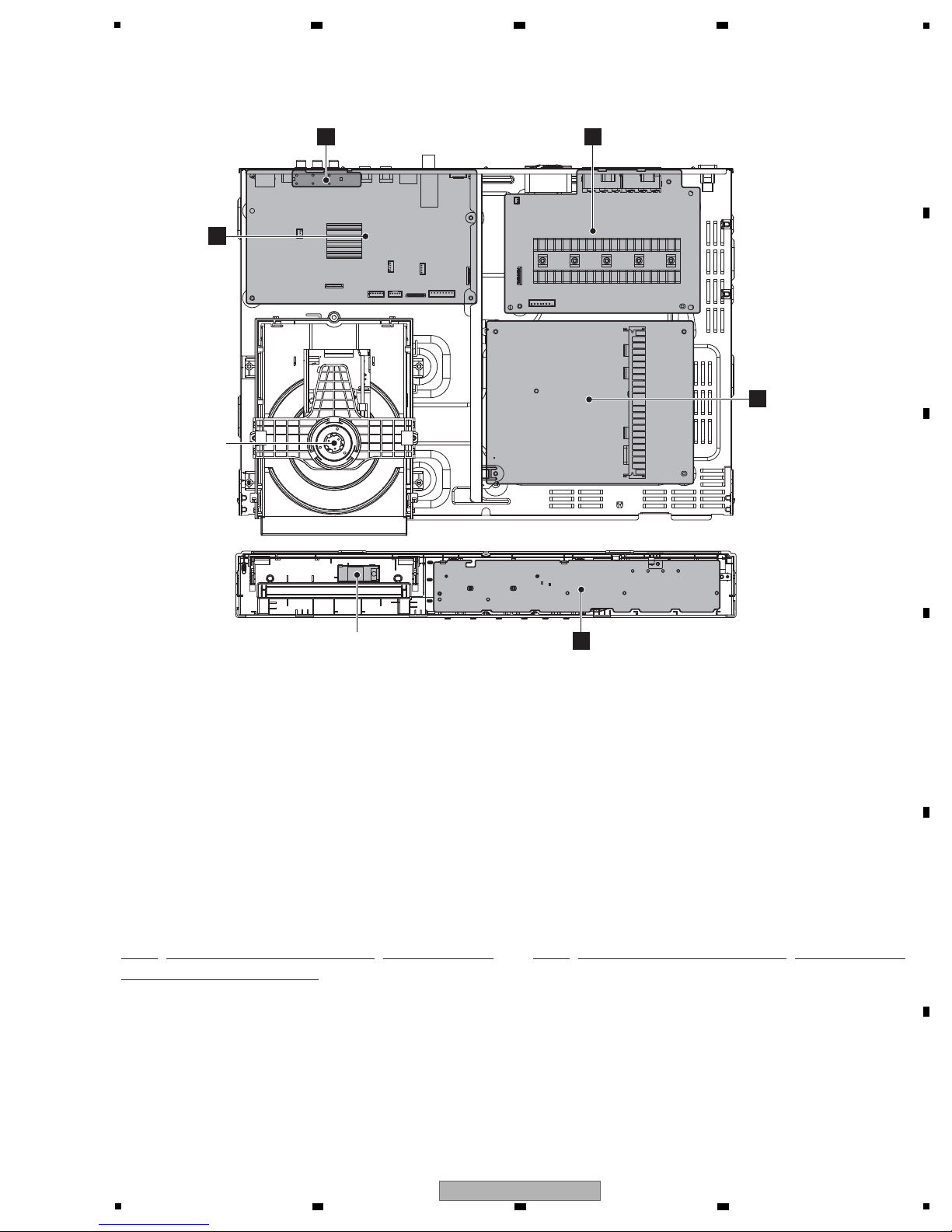
1..MAIN BOARD ASSY
08-H555DU-MA1R/YXV
1..FRONT BOARD ASSY 08-BCS727-FVY
1..AMP BOARD ASSY AZW7611
(XV-BD422B, XV-BD122B)
1..AMP BOARD ASSY AZW7612
(XV-BD122FSB)
1..AV BOARD ASSY AZW7613
1..SYSTEM POWER SUPPLY ASSY 08-K250HE-PW1
LOADER ASSY 08-LTCA19-222026
Mark No. Description Part No. Mark No. Description Part No.
LIST OF ASSEMBLIES
NOTES: - Parts marked by “NSP” are generally unavailable because they are not in our Master Spare Parts List.
-
The > mark found on some component parts indicates the importance of the safety factor of the part.
Therefore, when replacing, be sure to use parts of identical designation.
D
AV BOARD
ASSY
A
MAIN BOARD
ASSY
LOADER
ASSY
C
AMP BOARD
ASSY
E
SYSTEM POWER
SUPPLY ASSY
B
FRONT BOARD ASSYWi-Fi MODULE
3.3 PCB LOCATIONS
6 7 8
A
B
C
D
E
F
5
XV-BD422B
6 7 8
7
1
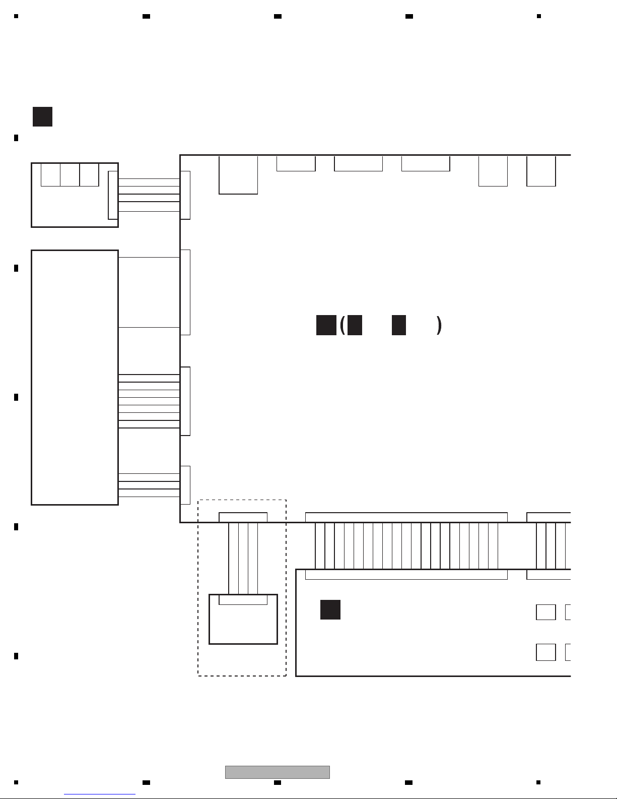
XP5 XP4
1J6J7J5R_XUA5
GND
L_XUA3ACR J4 J5
GND P2
1 CVBS_O 1
XP7
45
1
XP10
TPIC_A+ 8
TPIC_ATPIC_BTPIC_B+
U/C
V/W
W/V
C/U 1
XP5
TPIC_TRAYIN# 4
MGND
TPIC_LOAD+
TPIC_LOAD- 1
71PX31PX
6
1PX
102141
GND
USBP1
USBM1
WIFI_VCC
VOL+
VOL-
KEY1
KEY2
P-24V
GND
+12V_D
GND
STBY_3V3
SPI_CLK
SPI_DAT
SPI_CS
IR_IN
PWM_LED
GND
MP3_L
GND
MP3_R
GND
MIC
USB_VCC1
GND
USBM2
USBP2
USBM0
6021
606SX3PX
41
JACK603 JA
P801 P8
USB1 US
AUX R
AUX L
CVBS
Optical
IN 1
Optical
IN 2
HDMI IN 2 HDMI IN 1 HDMI OUT
LAN (10/100)
MIC
P
MAIN BOARD ASSY
(08-H555DU-MA1R/YXV)
NOT USED
A
FRONT BOARD ASSY
(08-BCS727-FVY)
B
AV BOARD ASSY
(AZW7613)
D
A
1/13-A13/13
LOADER ASSY
(08-LTCA19-222026)
Wi-Fi MODULE
4. BLOCK DIAGRAM
4.1 OVERALL WIRING DIAGRAM
A
B
2 3 4
C
D
E
F
8
1
XV-BD422B
2 3 4
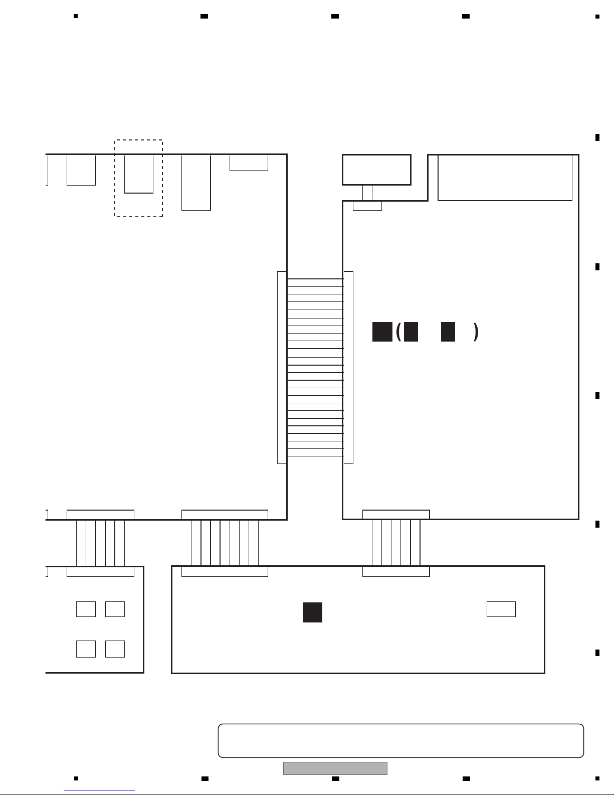
XP15
J5
J8
JK701
8PX1NUT
XP11 XP703
24 BKEN_ERR 1
PDN
AMP_DET
SHUTDOWN
POWER
GND
GND
+12V_D
3.3V
+12V_D
3.3V
DSP_RST
AMP_MUTE
GND
AMP_SDA
AMP_SCL
GND
I2S_MCLK
GND
I2S_BCK
I2S_DATA2
I2S_DATA1
I2S_LRCK
1 I2S_DATA0 24
207PX1PX71PX
161861
USB_VCC1
GND
USBM2
USBP2
USBM0
USBP0
GND
VCC_D
VCC
VCC
GND
+12V
GND
-24V
GND
GND
GND
+34V
+34V
+34V
161816
305NOC205NOC606SX
JACK603 JACK602 CN501
P801 P802
USB1 USB2
Optical
IN 1
AC IN
Speaker Output
Dock
for iPod
FM
Bluetooth
Adapter
MIC
Porta
ble
AMP BOARD ASSY
C
SYSTEM POWER SUPPLY ASSY
(08-K250HE-PW1)
E
DC FAN
C
1/3-C3/3
-
When ordering service parts, be sure to refer to "EXPLODED VIEWS and PARTS LIST" or "PCB PARTS LIST".
-
The > mark found on some component parts indicates the importance of the safety factor of the part.
Therefore, when replacing, be sure to use parts of identical designation.
NOT USED
(XV-BD422B, XV-BD122B: AZW7611)
(XV-BD122FSB: AZW7612)
5
6 7 8
A
B
C
D
5
6 7 8
XV-BD422B
E
F
9
1
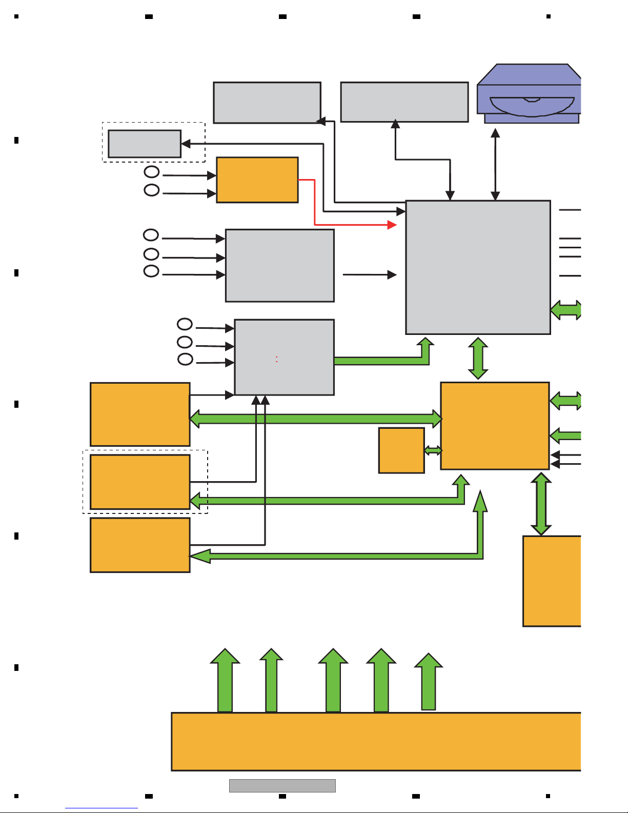
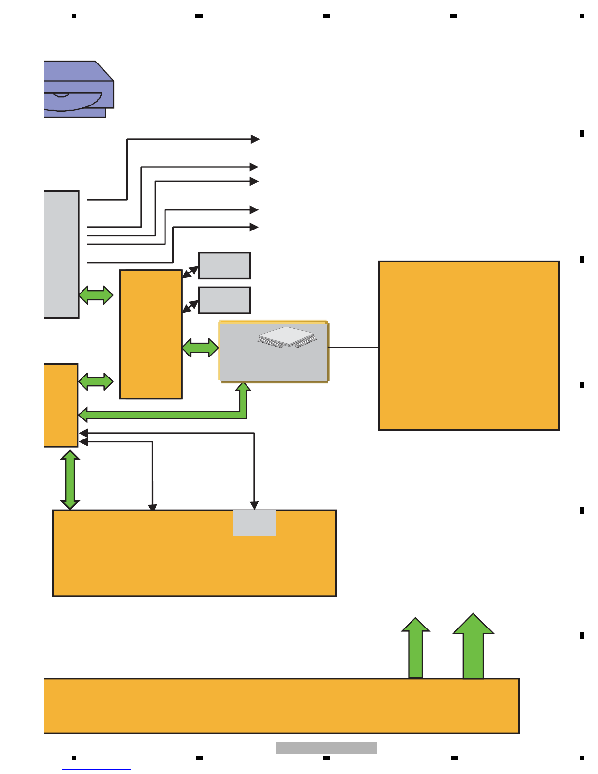
Tuner
FM+RDS
MPEG Deco der
AUX IN
ADC CS5346
I2S
MT8555
MCU
NUC100
RF
POWER
+12V
+5VDGND
MGND
NFLA SH
2Gbit
DDR3*4
64M*16*4pcs
DRIVER
CONTROL
I2C
SPI
KE
CO
Bluetooth)
(option)
I2C
UART
IPOD docking
analog
UART
WIFI
SPDIF change &
switch
OPTI IN
PortableIN
HDMI IN
HDMI IN
SPDIF
I2S
(HDMI)ARC IN
OPTI IN
FRON
HDMI Swtich
NXP19998L
MIC IN
CP for
IPOD
SPI
-24V
NOT USED
NOT USED
2 3 4
4.2 OVERALL BLOCK DIAGRAM
A
B
C
D
E
F
10
1
XV-BD422B
2 3 4
er
BD LOADER
I2S
USB 2.0
CVBS Output
POWER SUPPLY
I2C
+34V
AUDIO
PROCESSOR
AGND
PWM
KEY,LED
CONTROL
USB 2.0
HDMI OUT
RJ45
FRONT PANEL(VFD DISPLAY,KEY,LED)
DSP
DA707
I2S
IR
AMP: TAS5352*4
SPI
SDRAM
FLASH
5
6 7 8
A
B
C
D
E
5
XV-BD422B
6 7 8
F
11
1
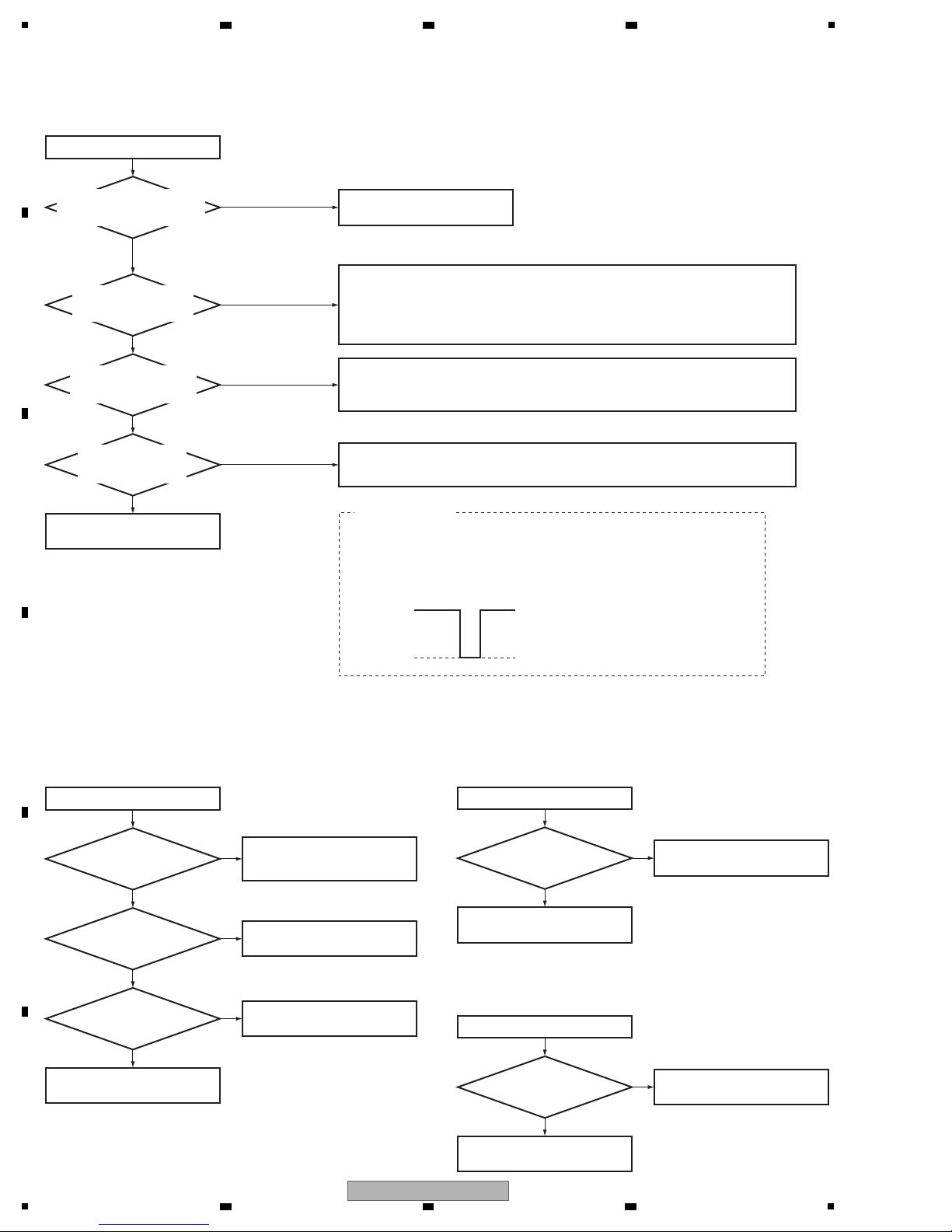
No power
No power
Which Power button, the one on
the remote control unit or on
the main unit, is disabled?
Is there 5 V on pins 5
and 6, 12 V on pin 3 of XP1
of MAIN BOARD Assy?
No
Check for any abnormality with the connection and connectors that connect the
POWER BOARD Assy and MAIN BOARD Assy.
If there is no abnormality:
· If neither 5 V nor 12 V are output, go to the flowchart for "Neither 5 V nor 12 V are output."
· If only 5 V is not output, go to the flowchart for "+5 V power is not output."
· If only 12 V is not output, go to the flowchart for "+12 V power is not output."
Check for any abnormality with the connection and connectors that connect the MAIN
BOARD Assy and FRONT BOARD Assy.
If there is no abnormality, replace the MAIN BOARD Assy.
To the flowchart for "The remote
control unit does not function"
Only the Power button
of the remote control unit
Both, or the Power button
of the main unit
Yes
Is there 3.3 V on pin 9,
12 V on pin 7 of XP3
of FRONT BOARD Assy?
No
Yes
Replace S608.
If replacement does not resolve the problem, replace the FRONT BOARD Assy.
1. Perform a conduction test, using a tester, with the main unit turned OFF.
2. Check the waveform at Pin 3 (KEY_POW) of the XP13 on the MAIN BOARD Assy.
With SW1 OFF: 3.3 V, With SW1 ON: 0 V
Checking of S608
Does S608 on the
FRONT BOARD Assy
function properly?
No
Yes
Replace the MAIN BOARD Assy.
Waveform of KEY_POW
3.3 V
0 V
Neither 5 V nor 12 V are outpu
Yes
Neither 5 V nor 12 V are output
Is the AC input voltage
normal?
Is the voltage of CE501
between 310 V to 390 V?
No
Check the connection of CN501
on the POWER BOARD Assy.
No
Chek the soldering of BD501 and
F501 are normal.
Yes
Is the voltage of CE505
between 5.8 V to 6.4 V?
No
Chek the soldering of D506 and
ZD502 are normal.
Yes
Replace the POWER BOARD
Assy.
Replace the POWER BOARD
Assy.
Replace the POWER BOARD
Assy.
+5 V power is not output
Yes
+5 V power is not output
Is the voltage of CE509
+5 V?
No
Chek the soldering of D509 and
D510 are normal.
+12 V power is not output
Yes
+12 V power is not output
Is the voltage of CE506
+12 V?
No
Chek the soldering of D508 is
normal.
5. DIAGNOSIS
5.1 TROUBLESHOOTING
A
2 3 4
B
C
D
E
F
12
1
XV-BD422B
2 3 4

5
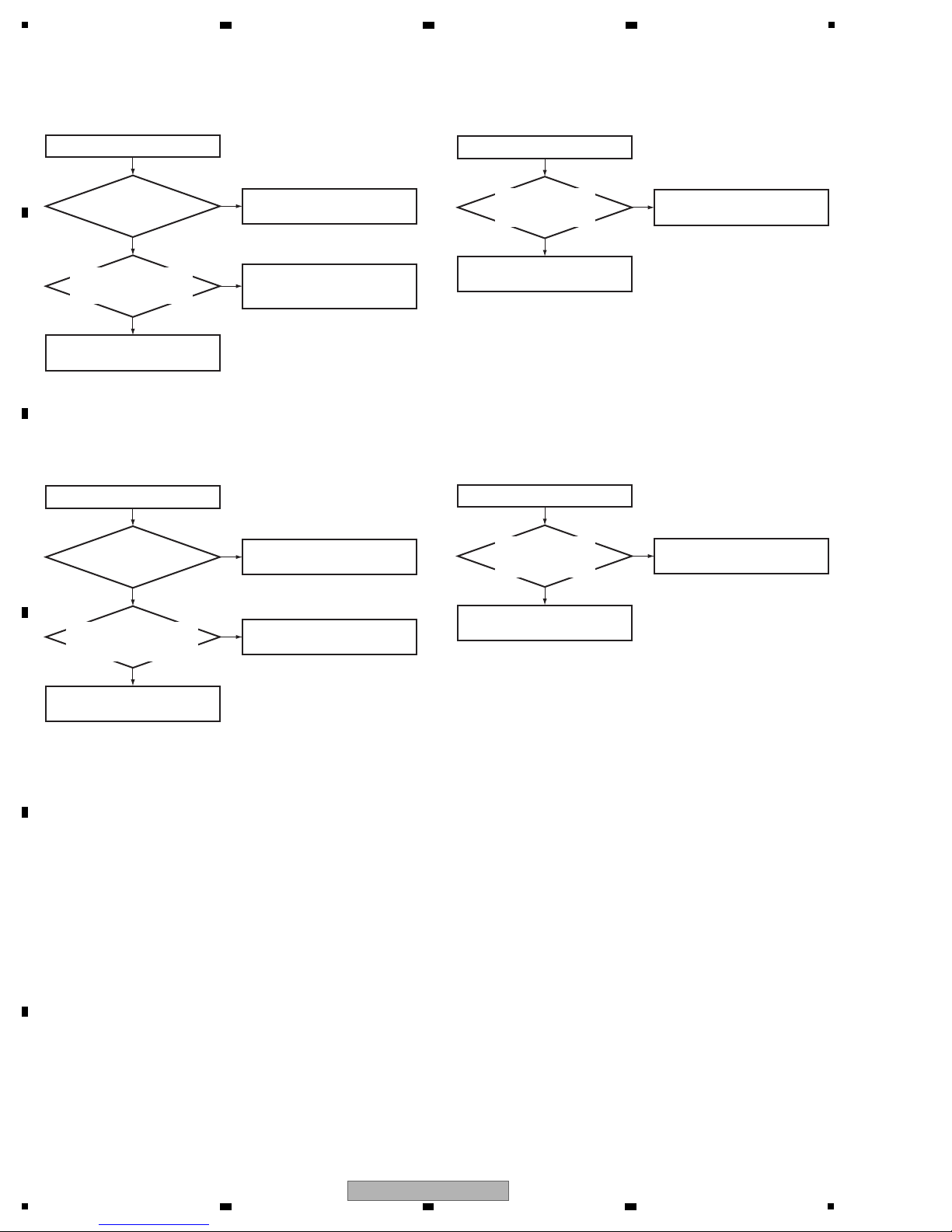
Remote control unit does not function
Remote control unit does not function
Yes
Yes
Is the battery of the remote
control exhausted?
No
No No
No
Replace the battery for remote
control.
Is remote control signal on
IR601 of FRONT BOARD
Assy normal?
Is there 3.3 V on XP3 pin 9
of FRONT BOARD Assy?
Is there remote control
signal on XP13 pin 13 of
MAIN BOARD Assy?
Yes
Yes
Replace the MAIN BOARD Assy.
Replace the FRONT BOARD Assy.
No audio output
No audio output
Yes
Yes
Yes
Yes
Are AMP IC (U710 to U713)
normal?
No
Replace U710 to U713.
Replace the speaker.
Is the +34 V voltage on AMP
board normal?
Are the output of U714 normal?
(U714: pin 40-47, pin 49-52)
Is the VALID signal (R774) high?
No
Refer to "NO +34 V output".
Are there signals of I2S?
(XP703: Pin 18, 20 to 24)
No
Check the connect line.
No
Replace U714.
Can’t read disc or can’t open the tray
Can’t read disc or can’t open the tray
Yes
Is the rotation of the
LOADER Assy normal?
No
Check the connection 4 pin cable
from the MAIN BOARD Assy.
Chek the soldering of R204 and
R205 are normal, or replace the
MAIN BOARD Assy.
No
Check the soldering of R946 and
R947 are normal. Check the voltage
of U11 (Pin 3) is OK. (about 12 V)
Yes
Are 45 pin and 8 pin cables
of MAIN board connected to
the LOADER Assy properly?
No
Connect those cables tightly.
Replace the LOADER Assy.
Is the voltage of
U11 (Pin2) normal?
(about 9 V)
No
Yes
Yes
Are R204, R205 normal?
(The voltage between two
resistance is 1.5 V.)
No display on VFD, and buttons do not work
Yes
No display on VFD,
and buttons do not work
Are the supply voltages
on MAIN BOARD Assy
normal?
1. Be soldered properly between
U135 and pins of VFD on
FRONT BOARD Assy?
2. Is not a circuit connected to
K135 to K140 and S608 broken?
Is there -24 V on pin 5, 12 V
on pin 7, 3.3 V on pin 9 of XP13
of MAIN BOARD Assy?
No
No
No
Solder parts again,
be connected correctly.
Solder parts again.
Yes
Yes
No
Replace the FRONT BOARD Assy.
Replace the FRONT BOARD Assy.
Are Q7, Q207, Q209,
U1 to U4, U15 performed
soldering of normally?
6 7 8
A
B
C
D
E
F
5
XV-BD422B
6 7 8
13
1
Can not connect to network by LAN
Can not connect to network
Yes
Yes
Is LFE8634 (U14) on
MAIN BOARD Assy
normal?
No
Check the soldering of U14 is
normal.
Are R133, R134, R579, R580
and R583 on MAIN BOARD
Assy normal?
No
Check the soldering of
R133, R134,
R579 and R580
are normal.
Replace the MAIN BOARD Assy.
No output by "OPTICAL IN 1 or 2"
No output by "OPTICAL IN 1 or 2"
Yes
Are the connector of
HDMI in J4 and J5 on MAIN
BOARD Assy normal?
No
Check the soldering of
J4 and J5
on MAIN BOARD Assy are normal.
No output by "HDMI IN 1 or 2"
No output by "HDMI IN 1 or 2"
Yes
Are the connector of
HDMI in J6 and J7 on MAIN
BOARD Assy normal?
No
Check the soldering of
J6 and J7
on MAIN BOARD Assy are normal.
Replace the MAIN BOARD Assy.
Replace the MAIN BOARD Assy.
No analog video display
No analog video display
Yes
Is P8 on AV BOARD
Assy normal?
Is the connection
of MAIN and AV BOARD
Assemblies is normal?
No
Check the soldering of
P8
on
AV BOARD Assy are normal.
Yes
No
Check whether connection of
MAIN and AV BOARD Assemblies
is normal.
Replace the MAIN BOARD Assy.
A
2 3 4
B
C
D
E
F
14
1
XV-BD422B
2 3 4
5
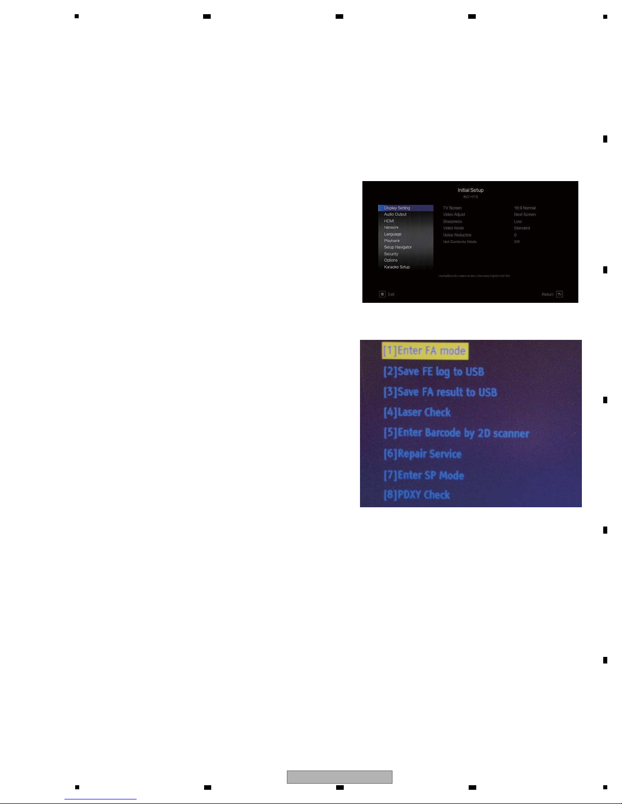
In Service Mode, there is a mixture of Design and Development, Production Line Menu and Service Menu.
Here, menu items that are usable in Service and instructions are listed.
Only use the menu explained in this document. Others are for Design and Product lines.
1. Press [Home Menu] on the remote controller and select
"Initial Setup" from the home menu.
2. Pressing the number keys on the remote control in the
following order [5] ⇒ [1] ⇒ [7] ⇒ [7] will display the Menu
screen. (If it does not appear, slowly press the number
keys with a 1 second interval.)
1. HOW TO ENTER TO SERVICE MODE
2. DESCRIPTION OF EACH ITEM
[1] Enter FA mode
Implemented when exchanging the LOADER Assy and MAIN BOARD Assy. Refer to "FA Mode" for details.
[2] Save FE log to USB
For Design and Development purposes and cannot be used for Service.
[3] Save FA result to USB
For Design and Development purposes and cannot be used for Service.
[4] Laser Check
Verifies laser diode. Refer to "Laser Check" for details.
[5] Enter Barcode by 2D scanner
For Production line purposes and cannot be used for Service.
[6] Repair Service
For the former model and will not be used to exchange this Loader.
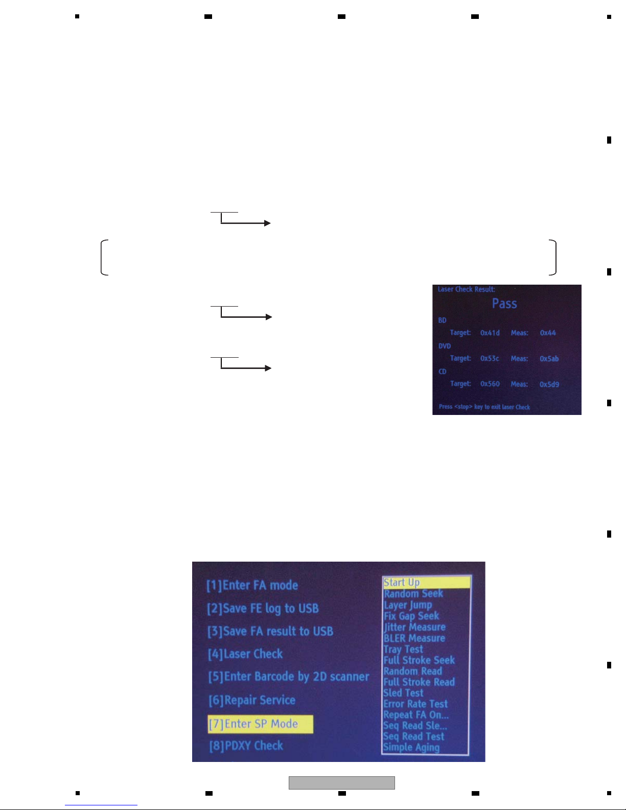
[7] Enter SP Mode
Mainly for Production Line, but some items can be used in Service. Please see "SP Mode" for details.
[8] PDXY Check
Verifies misalignment of optical axis. Refer to "PDXY Check" for details.
6 7 8
6. SERVICE MODE
6.1 SERVICE MODE
A
B
C
D
5
6 7 8
XV-BD422B
E
F
15
1
3. DETAILED DESCRIPTION OF ITEMS USED IN SERVICE
1. [1] Enter FA mode
1 Select "[1] Enter FA mode" with the up-and-down key on the remote control on the Service Mode screen and press the
[ENTER] key. (Window below will appear)
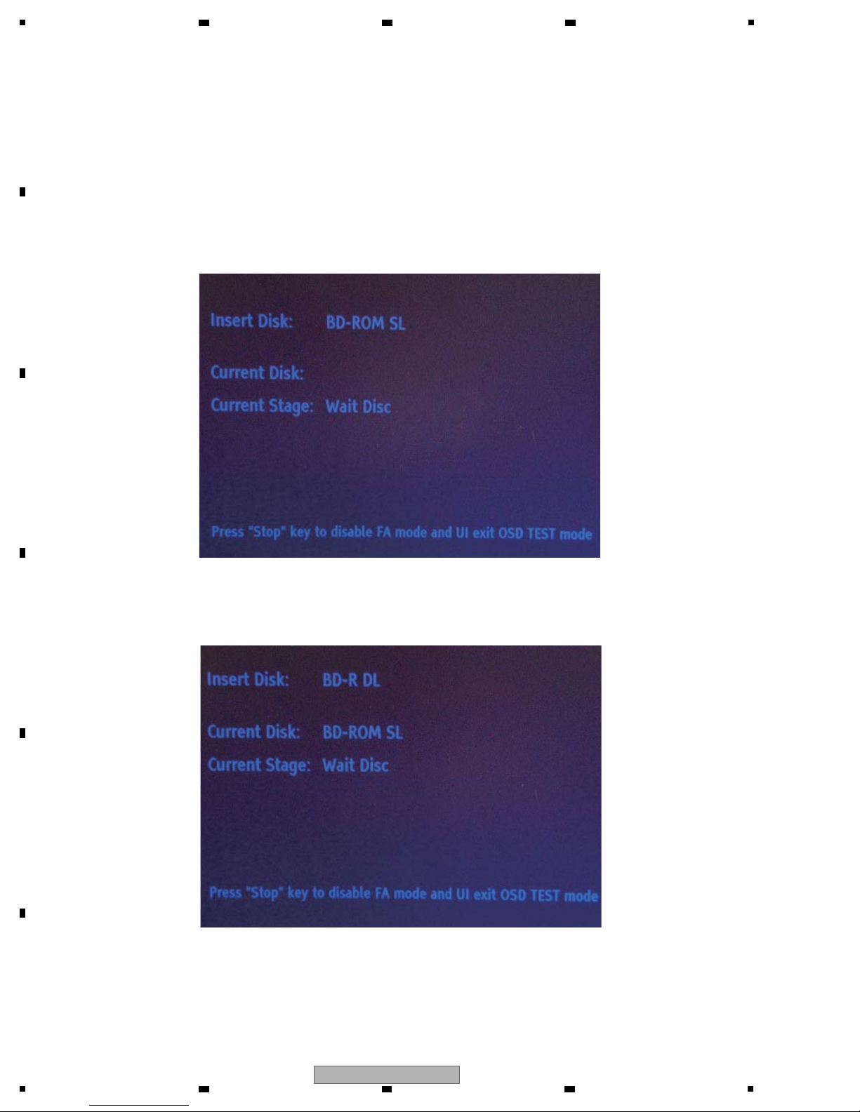
2 The tray will open automatically, so insert GGV1368 and close the tray manually. (push the tray in)
3 Adjustments will initiate, and when they are properly completed, the tray will re-open and [Insert Disc: BD-R DL]
will appear.
4 Remove the disc from the tray and press the [Stop] key.
You will exit Service Mode and return to the Home Menu screen and finish.
In "FA mode," playback of the pick-up area is adjusted first, and then playback verification processis done on all playable discs.
Adjustments on initial playback need to be made when exchanging the Loader and MAIN BOARD Assy in Service,
so implement "FA mode" as in the following instructions.
A
2 3 4
B
C
D
E
F
16
1
2 3 4
XV-BD422B
5
1 Select "[4] Laser Check" with the b key from the Service Mode screen and press the "ENTER" key.
(perform without disc in tray)
2 After a few seconds, measurement and judgment results will be displayed as follows, and the tray will open automatically.
If all Measurement values (Meas) are less than the total numeric value of the Target value (hex) and 80 (hex) combined,
[PASS] will appear, and if any of them goes over, [NG] will appear.
2. [4] Laser Check
Verifies the output value of each laser diode inside the pick-up area. Implement according to the following procedures.
3. [7] Enter SP Mode
There are 15 items in the SP Mode, the main items being for Production line and Design/Development.
The following is to explain items usable in Service. Other items require time for completion, or are not suited for
Service purposes. If you select them by mistake, press the [Stop] key to end that item you accidentally selected.
(none of the items will affect the main unit)
Example
BD
Target: 0x41d
Meas: 0x43 OK because
0x41d+0x80=0x49d
Meas is 0x49d or less
DVD
Target: 0x53c
Meas: 0x5a7 l OK
0x53c+0x80=0x5bc
CD
Target: 0x560
Meas: 0x5d7 l OK
0x560+0x80=0x5e0
BD Measurement values: The hexadecimal single-digit will not be displayed in Meas. Therefore
in the above example, Measurement values of up to 0x49 are considered OK, and 0x50 are considered NG.
("0x" is simply to express the hex, so it is not necessary in the calculation)
6 7 8
A
B
C
D
XV-BD422B
5
6 7 8
E
F
17

1
1
Select "[7] Enter SP Mode" with the b key from the Service Mode screen, and press the [ENTER] key.
2
The SP Mode window menu will be displayed, so select "Start Up" and press the [ENTER] key.
3 The tray will automatically open and the dedicated screen will appear. Place the disc you wish to useon the tray,
and push it in manually. ([Close] key will not function)
4 tart Up mode will be initiated, and count will start. Implement 20,000 times (4E20 in hex), and if no errors occur,
"Pass" will appear.If errors do occur, they will be counted. Therefore, errors can be identified without finishing the
process.
1 Select "[7] Enter SP Mode" with the b key from the Service Mode screen, and press the [ENTER] key.
2 The SP Mode window menu will be displayed, so select either "Jitter Measure ""BLER Measure,"
and press the [ENTER] key.
3 The tray will automatically open and the dedicated screen will appear. Place the disc you wish to use on the tray,
and push it in manually. ([Close] key will not function)
4 The tray will reopen automatically. Measurement will start when you push the tray in manually.
5 When test is completed, "Pass" or "NG" is displayed.
3-1. Start Up
[ Content of test ]
Implements initial movement of the disc servo continuously. Implement the following process 20,000 cycles.
Measures the Jitter or the Block Error Rate (BLER) of the disc inserted.
Only Pass or NG will be displayed, not Measurement values.
All of CD, DVD, and BD can be judged.
[ Instructions ]
[ Effective indications ]
3-2. Jitter Measure / BLER Measure
[ Content of test ]
[ Instructions ]
[ Effective indications ]
• Tray sometimes does not open, discs sometimes are not recognized, discs sometime do not playback.
(When indications are related to discs, implment on the type of disc which has been pointed out.
If it is the disc on which the indications occurred, possibility of reoccurrence is higher.)
Defect related to playback. (blocked noise, sound jumping, image jumping, disc is paused, freeze of screen etc.)
However, even if Pass is displayed after this test, it is difficult to determine that the Driver is normal with these
Pass judgments only.
If an NG is generated in a specific disc only, the defect is likely to be caused by the disc. If an NG is gener ated in
other discs t oo, t he defect is likely to be caused by the drive part.
.
Tray Close
l
.
Foucus ON
l
.
TOC Read
l
.
Tray Open
(1 cycle 15 seconds x 20000=completed in approx. 83 hours 20 minutes)
Can be implemented on all of CD, DVD, and BD. Cannot change disc during process.
A
2 3 4
B
C
D
E
F
18
1
XV-BD422B
2 3 4
5
3-3. Simple Aging
[ Content of Test ]
Performs random playback of disc randomly. Implement the following process 800 cycles.
[ Instructions ]
1 Select "[7] Enter SP Mode" with the b key from the Service Mode screen, and press the [ENTER] key.
2 The SP Mode window menu will be displayed, so select "Simple Aging" and press the [ENTER] key.
3 The tray will automatically open and the dedicated screen will appear. Place the disc you wish to use on the tray,
and push it in manually. ([Close] key will not function)
4 The tray will reopen automatically. Aging will start when you push the tray in manually.
Note 1: [Total test count] display should always be 1 (essentially, 9C40, which is the hex of the 40000, the total of
Random 50-time playback x 800 times should be displayed.
Note 2: Accumulated sum for [Current test count] is counted up until "9C3D" (39997 in decimal), however later it is
expressed as "32" and is finished.
Note 3: DVD and BD disc can be checked with Single Layer (SL) disc only.
If they are checked with Dual Layer (DL) disc, an Error is generated.
Note 4: Set [Auto Power OFF] function in the setting of main unit to [OFF].
If the function is executed in any setting status, the power supply is turned OFF at the time.
.
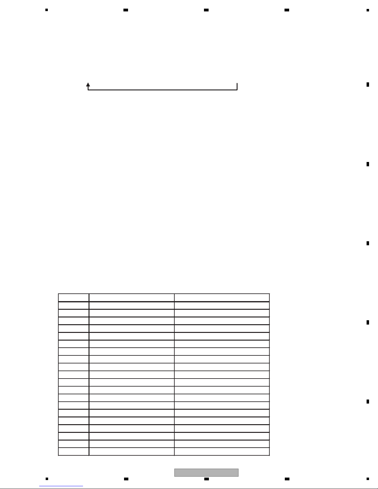
Error List
The following serves as the Error List generated in SP Mode.
.
Tray close l .50 times of short playback on voluntary points
.
Tray open
1cycle BD : 75 seconds x 800 times = Completed in a total of approx. 16 hours 40 minutes
DVD: Approx. 100 seconds x800 times = Completed in a total of approx. 22 hours 12 minutes
CD : Approx. 105 seconds x800 times = Completed in a total of approx. 23 hours 20 minutes
l
Error code Error name Discription
12 PW R_CURVE_ ERROR Power c urve chk-sum error
22 STARTUP_ TIMEOUT_ERROR Over time-out criteria
23 MEDIA_MISMATCH Wrong disc
25 DISCID_ERROR 0x25 Disc ID err o r
26 MEDIUM_SUPPORT_ERROR Unsupported disc
31 TRAYOUT_ERROR Over tray-out t ime-out crite ria
32 TRAYIN_ERROR O v er t r ay- in t ime- out criteria
33 FLASH_UPDATE_ ERROR Updating FA result failed
36 OPU_TEMP_ERROR Abnormal OPU temperature
41 SEEK_TIMEOUT_ERROR Over seek time-out crit e ria
42 SEEK_CMD_FAIL_ERROR Seek cmd fa ile d
51 READ_TOC_ERROR Read TOC cm d f ailed
52 TOC_TIM EO UT_ERROR Over read TOC time-out cr it er ia
61 PIPO_TI M EO UT_ERROR Over time-out criter ia
62 PIPO_C1C2_ERROR Read PIPO cmd failed
63 PIPO_C1C2_OVER Over PIPO criteria
71 RD_CMD_FAIL_ERROR Read cmd failed
72 RD_CMD_ERROR Cmd error or illegal mode
73 RD_TIME_OUT_ERROR Over read cmd time-out cr iter ia
81 CHECK_FA_TABLE_ERROR FA table chk-sum error
6 7 8
A
B
C
5
XV-BD422B
6 7 8
D
E
F
19

1
4. [8] PDXY Check
[ Instructions ]
[Effective indications]
Defect related to playback. (block noise , sound jumping, image jumping, dis c i s paused, freeze o f screen etc.)
If an NG is generated in a specific disc only, the defect is likely to be caused by the disc. If an NG is generated in
other discs too, t he defect is likely to be caused by the pick-up part. If the measurement val ue is very close to 40% even if
an NG is not generated, the NG is likely to be caused by the disc.
For PDXY Check, the misalignment of pick-up optical axis can be checked.
The optical axis misalignments of X-axis and Y-axis are displayed [PDX] and [PDY] with %, respectively.All of CD, DVD,
and BD can be measured. The method for calculating PDX and PDY is shown below.
1
Insert a disc (BD, DVD, CD) in a nomal mode. If the playback starts, pause it.
Display the home menu and enter into the Service Mode.
In this mode, the measurement can be carried out at an arbitrary place. After a disc is inserted, play and stop the point
you want to measure, and then enter into the Service Mode.
(The pick-up position does not return even in this status. The measurement at the place is available.)
2
Select "[8] PDXY Check" wi t h t h e b key from the Service Mode screen, and press the [ENTER] key.
3
After the measurement is started and completed, the measurement value is displayed.
If the value is within the reference value, "Pass" is displayed.
PDX = ((A+B)-(C+D)) / (A+B+C+D)
PDY = ((A+D)-(B+C)) / (A+B+C+D)
A
2 3 4
B
C
D
E
F
20
1
XV-BD422B
2 3 4
5
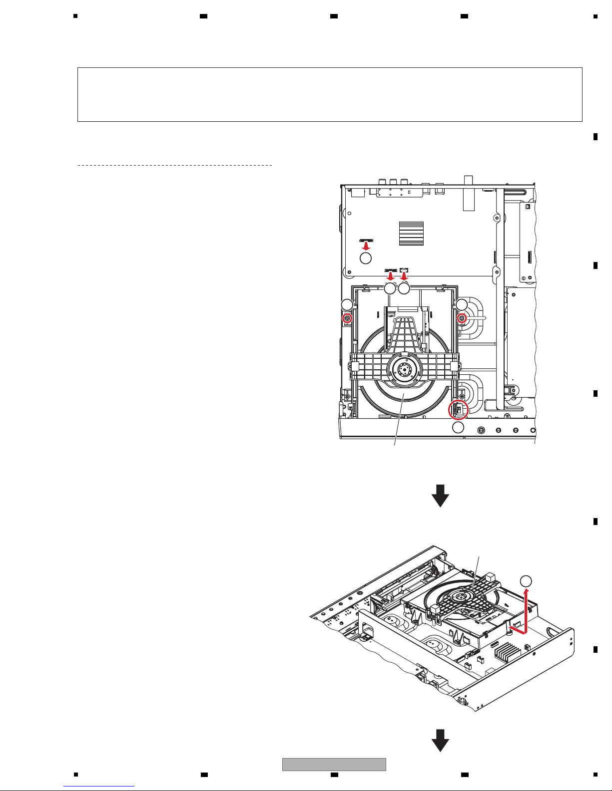
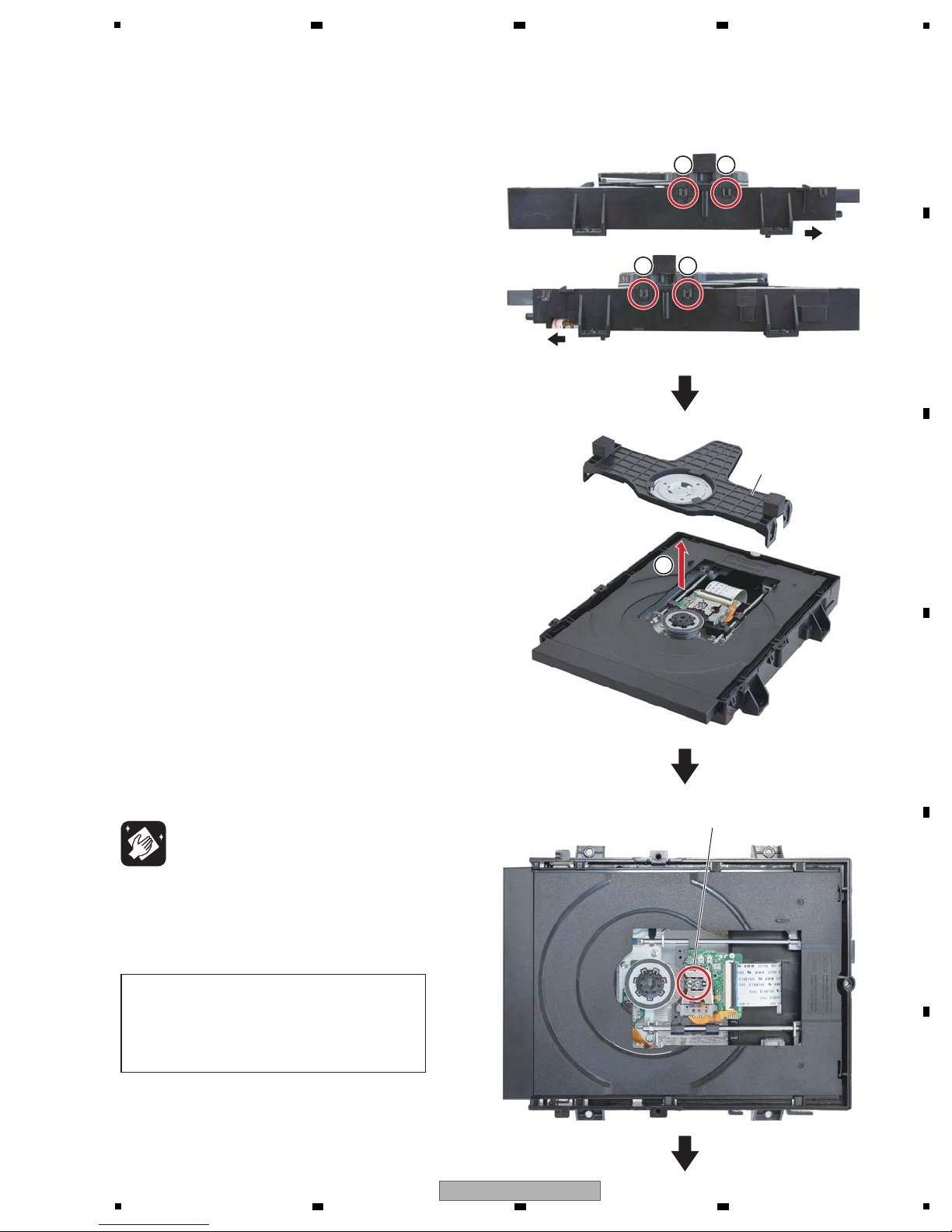
[1] LOADER Assy
(1) Disconnect the two flexible cables and one
connector.
(XP5, 7, 10)
(2) Remove the two screws.
(63-B30070-3H4)
(3) Unhook the one hooks.
(4) Remove the LOADER Assy.
2 2
3
4
LOADER Assy
LOADER Assy
XP7
XP10
XP5
11
1
• T op view
Remove the top cover by removing the six screws.
Note:
(1) Do NOT look directly into the pickup lens. The laser beam may cause eye injury.
(2) Even if the unit shown in the photos and illustrations in this manual may differ from your product, the
procedures described here are common.
6 7 8
7. DISASSEMBLY
A
B
C
D
E
5
XV-BD422B
6 7 8
F
21
1
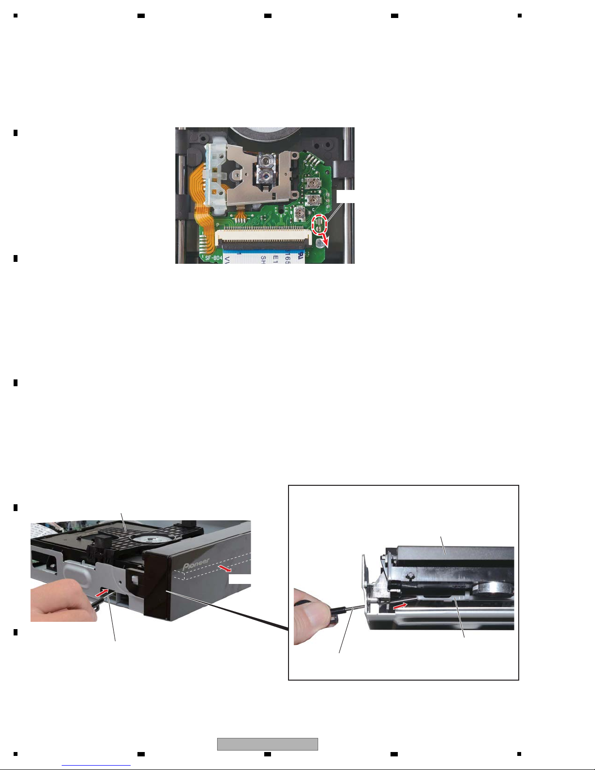
Case of replacing to a New LOADER Assy
After connecting LOADER Assy and MAIN BOARD Assy with FFC, please remove solder at protection point to the arrow-mark
direction by using soldering iron with your right-hand while holding the pick-up portion with your left-hand.
(Photo shows the situation after the removal of solder.)
Protection point
When the tray cannot be opened because the power cannot be turned on, it can be opened using the emergency disc
ejection rod (GGF1529). (A long, thin rod about 1 mm in diameter can be used in place of the rod.)
Insert emergency disc ejection rod (GGF1529) into the side located at the chassis, and slide the loading rack in the
LOADER Assy in the direction of the arrow, as indicated in the photo.
If the tray pops out a little, fully pull it out by hand.
How to open the tray when the power cannot be on
LOADER Assy
LOADER Assy
Emergency disc ejection rod
(GGF1529)
Emergency disc ejection rod
(GGF1529)
Loading rack
Tray open
Note: The Emergency disc ejection rod will not reach
the Loading rack unless it is inserted in slant
upward direction.
A
2 3 4
B
C
D
E
F
22
1
XV-BD422B
2 3 4
1 1
1 1
Front
Front
(1) Unhook the four hooks.
(2) Remove the top cover.
Top cover
2
Cleaning
Pickup lenses
Clean the pickup lenses when it is stained, using
the following cleaning materials:
Cleaning liquid : GEM1004
Cleaning paper: GED-008
Caution:
The pickup for Blu-ray is a high-precision
component; therefore, clean the lens with
enough care so as not to cause a misalignment
in the optical axis.
5
6 7 8
A
B
C
D
E
5
XV-BD422B
6 7 8
F
23
1
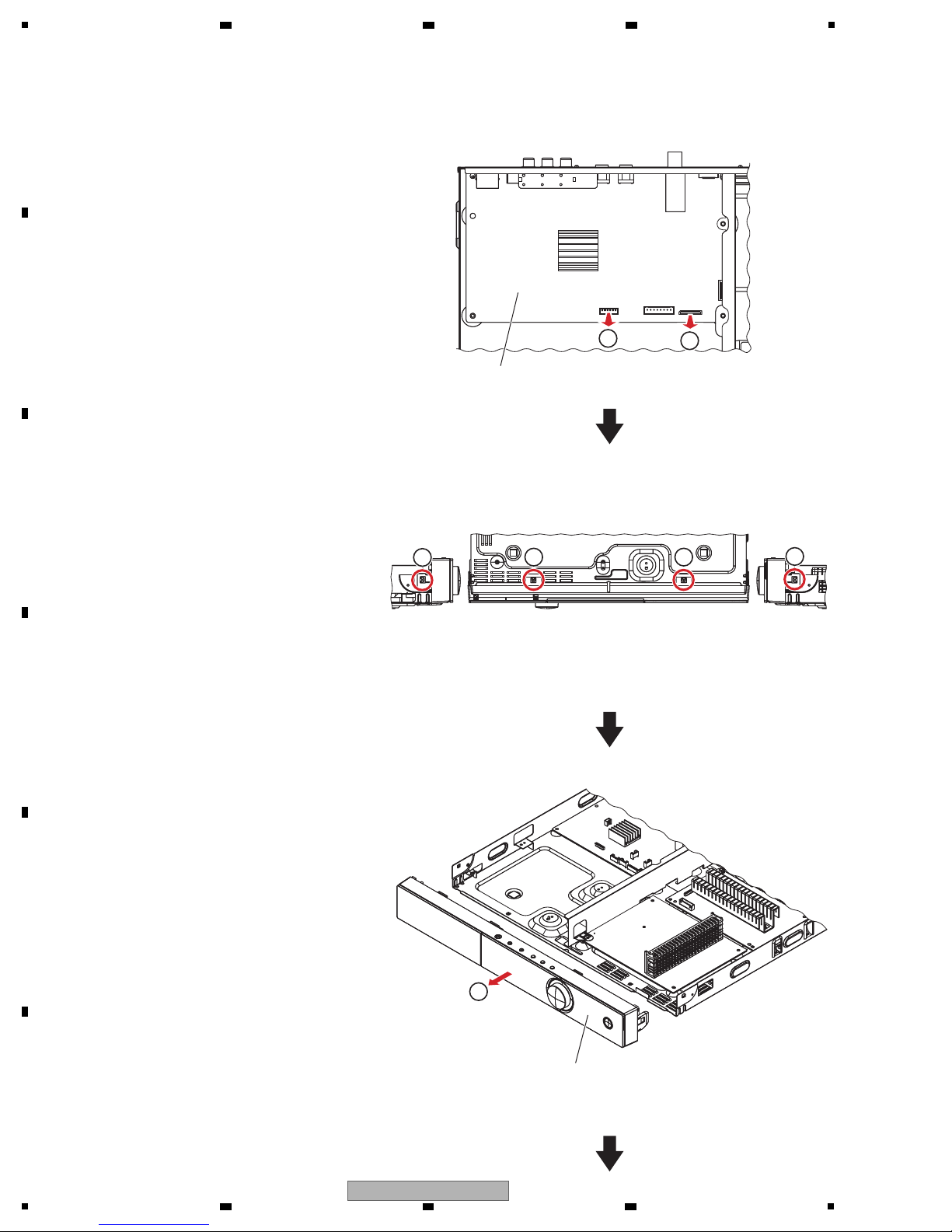
[2] Front Panel Section
(1) Disconnect the one flexible cable and one
connector.
(XP13, 17)
(2) Unhook the four hooks.
(3) Remove the front panel section.
XP13
XP17
MAIN BOARD Assy
Front panel section
2
2
3
2
2
1
• T op view
• Bottom view
1
A
B
2 3 4
C
D
E
F
24
1
XV-BD422B
2 3 4
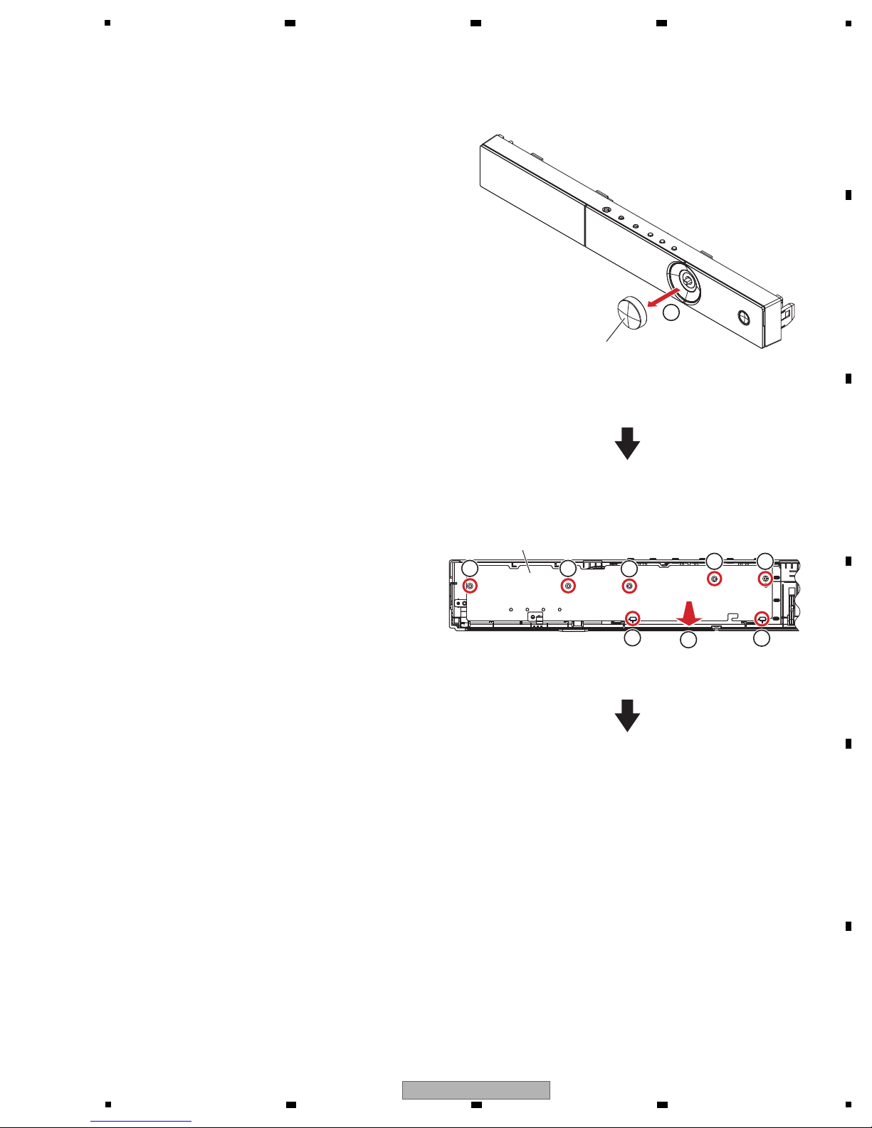
(4) Remove the VOL knob Assy.
(5) Remove the five screws.
(63-B26080-BF4)
(6) Unhook the two hooks.
(7) Remove the FRONT BOARD Assy.
VOL Knob Assy
FRONT BOARD Assy
5 5
5
6
7
6
5 5
• Rear view
4
5
6 7 8
A
B
C
D
E
5
XV-BD422B
6 7 8
F
25
1
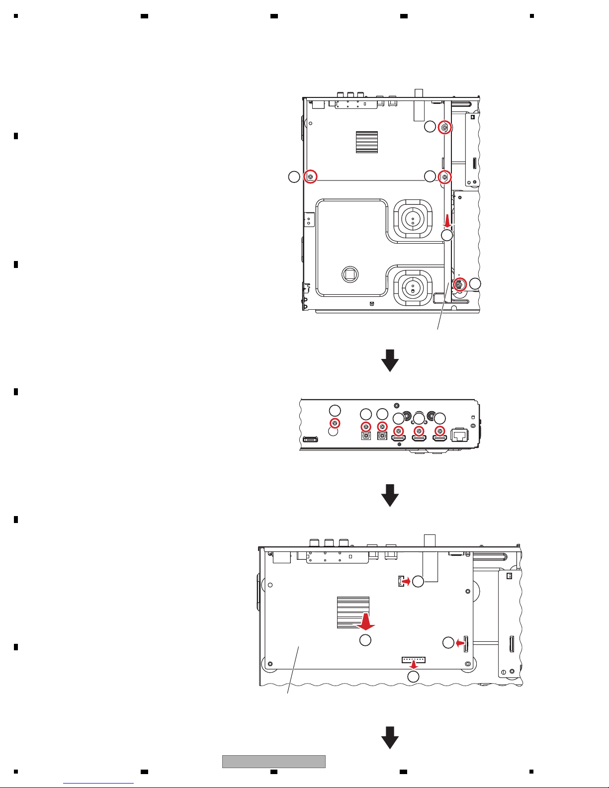
[3] MAIN BOARD Assy
(1) Remove the four screws.
(63-B30070-3H4)
(2) Remove the stay.
(3) Remove the three screws.
(63-B30070-3H4)
(4) Remove the three screws.
(64-B30040-304)
(5) Disconnect the one flexible cable and two
connectors.
(XP1, 4, 11)
(6) Remove the MAIN BOARD Assy.
Stay
4
4
4
3 3
3
1
1
1
1
• T op view
• Rear view
• T op view
2
XP11
XP4
XP1
MAIN BOARD Assy
5
5
5
6
A
B
2 3 4
C
D
E
F
26
1
XV-BD422B
2 3 4
 Loading...