

Page 1

Quick Start Guide | Guide rapide | Kurzanleitung
VSX-LX55
VSX-2021-K
Page 2
IMPORTANT
CAUTION
RISK OF ELECTRIC SHOCK
The lightning flash with arrowhead symbol,
within an equilateral triangle, is intended to
alert the user to the presence of uninsulated
“dangerous voltage” within the product’s
enclosure that may be of sufficient
magnitude to constitute a risk of electric
shock to persons.
WARNING
This equipment is not waterproof. To prevent a fire or
shock hazard, do not place any container filled with
liquid near this equipment (such as a vase or flower
pot) or expose it to dripping, splashing, rain or
moisture.
WARNING
Before plugging in for the first time, read the following
section carefully.
The voltage of the available power supply differs
according to country or region. Be sure that the
power supply voltage of the area where this unit
will be used meets the required voltage (e.g., 230 V
or 120 V) written on the rear panel.
VENTILATION CAUTION
When installing this unit, make sure to leave space
around the unit for ventilation to improve heat radiation
(at least 40 cm at top, 10 cm at rear, and 20 cm at each
side).
WARNING
Slots and openings in the cabinet are provided for
ventilation to ensure reliable operation of the product,
and to protect it from overheating. To prevent fire
hazard, the openings should never be blocked or
covered with items (such as newspapers, table-cloths,
curtains) or by operating the equipment on thick carpet
or a bed.
CAUTION:
TO PREVENT THE RISK OF ELECTRIC
SHOCK, DO NOT REMOVE COVER (OR
BACK). NO USER-SERVICEABLE PARTS
INSIDE. REFER SERVICING TO QUALIFIED
SERVICE PERSONNEL.
D3-4-2-1-3_A1_En
D3-4-2-1-4*_A1_En
D3-4-2-1-7b*_A1_En
DO NOT OPEN
The exclamation point within an equilateral
triangle is intended to alert the user to the
presence of important operating and
maintenance (servicing) instructions in the
literature accompanying the appliance.
Operating Environment
Operating environment temperature and humidity:
+5 °C to +35 °C (+41 °F to +95 °F); less than 85 %RH
(cooling vents not blocked)
Do not install this unit in a poorly ventilated area, or in
locations exposed to high humidity or direct sunlight (or
strong artificial light)
WARNING
To prevent a fire hazard, do not place any naked flame
sources (such as a lighted candle) on the equipment.
If the AC plug of this unit does not match the AC
outlet you want to use, the plug must be removed
and appropriate one fitted. Replacement and
mounting of an AC plug on the power supply cord of
this unit should be performed only by qualified
service personnel. If connected to an AC outlet, the
cut-off plug can cause severe electrical shock. Make
sure it is properly disposed of after removal.
The equipment should be disconnected by removing
the mains plug from the wall socket when left unused
for a long period of time (for example, when on
vacation).
CAUTION
The STANDBY/ON switch on this unit will not
completely shut off all power from the AC outlet.
Since the power cord serves as the main disconnect
device for the unit, you will need to unplug it from the
AC outlet to shut down all power. Therefore, make
sure the unit has been installed so that the power
cord can be easily unplugged from the AC outlet in
case of an accident. To avoid fire hazard, the power
cord should also be unplugged from the AC outlet
when left unused for a long period of time (for
example, when on vacation).
D3-4-2-1-1_A1_En
D3-4-2-1-7c*_A1_En
D3-4-2-1-7a_A1_En
D3-4-2-2-1a_A1_En
D3-4-2-2-2a*_A1_En
Replacement and mounting of an AC plug on the power supply cord of this unit should be performed only by qualified
service personnel.
IMPORTANT: THE MOULDED PLUG
This appliance is supplied with a moulded three pin mains plug for your safety and convenience. A 10 amp fuse is fitted in this plug.
Should the fuse need to be replaced, please ensure that the replacement fuse has a rating of 10 amps and that it is approved by ASTA or BSI
to BS1362.
Check for the ASTA mark or the BSI mark on the body of the fuse.
If the plug contains a removable fuse cover, you must ensure that it is refitted when the fuse is replaced. If you lose the fuse cover the plug
must not be used until a replacement cover is obtained. A replacement fuse cover can be obtained from your local dealer.
If the fitted moulded plug is unsuitable for your socket outlet, then the fuse shall be removed and the plug cut off and disposed of
safely. There is a danger of severe electrical shock if the cut off plug is inserted into any 13 amp socket.
If a new plug is to be fitted, please observe the wiring code as shown below. If in any doubt, please consult a qualified electrician.
IMPORTANT: The wires in this mains lead are coloured in accordance with the following code:
Blue : Neutral Brown : Live
As the colours of the wires in the mains lead of this appliance may not correspond with the coloured markings identifying the terminals in
your plug, proceed as follows;
The wire which is coloured BLUE must be connected to the terminal which is marked with the
letter N or coloured BLACK.
The wire which is coloured BROWN must be connected to the terminal which is marked with the
letter L or coloured RED.
How to replace the fuse: Open the fuse compartment with a screwdriver and replace the fuse.
D3-4-2-1-2-2*_A2_En
Information for users on collection and disposal of old equipment and used batteries
Symbol for
equipment
Symbol examples
for batteries
Pb
This product is for general household purposes. Any
failure due to use for other than household purposes
(such as long-term use for business purposes in a
restaurant or use in a car or ship) and which requires
repair will be charged for even during the warranty
period.
These symbols on the products, packaging, and/or accompanying documents mean
that used electrical and electronic products and batteries should not be mixed with
general household waste.
For proper treatment, recovery and recycling of old products and used batteries,
please take them to applicable collection points in accordance with your national
legislation.
By disposing of these products and batteries correctly, you will help to save valuable
resources and prevent any potential negative effects on human health and the
environment which could otherwise arise from inappropriate waste handling.
For more information about collection and recycling of old products and batteries,
please contact your local municipality, your waste disposal service or the point of sale
where you purchased the items.
These symbols are only valid in the European Union.
For countries outside the European Union:
If you wish to discard these items, please contact your local authorities or dealer and
ask for the correct method of disposal.
K058a_A1_En
K041_A1_En
En
2
Page 3

Thank you for buying this Pioneer
product. This Quick Start Guide
includes instructions for basic connections and operations to allow
simple use of the receiver. For
detailed descriptions of the receiver,
see the “Operating Instructions”
provided on the included CD-ROM.
The operating instructions can also
be downloaded from the Pioneer
website (http://www.pioneer.eu).
When using a Mac OS, place the
CD-ROM in a CD drive and then double-click on the CD-ROM icon to find
the PDF file (Operating Instructions).
Contents
01 Before you start
Checking what’s in the box ............................5
Loading the batteries ...................................... 5
About using AVNavigator
(included CD-ROM) ........................................ 5
Remote control ...............................................6
02 Connecting your equipment
Connecting your equipment .......................... 8
Determining the speakers’ application ........ 8
Placing the speakers ...................................... 9
Connecting the speakers ............................... 9
Installing your speaker system .................... 10
Selecting the Speaker system .....................11
About the audio connection ........................11
About the video converter ............................ 11
About HDMI ..................................................12
Connecting your TV and playback
components ..................................................13
Connecting an HDD/DVD recorder, BD
recorder and other video sources ...............14
Connecting a satellite/cable receiver or
other set-top box ........................................... 15
Connecting other audio components ......... 15
Connecting AM/FM antennas .....................16
MULTI-ZONE setup ....................................... 16
Connecting to the network through
LAN interface ................................................17
Connecting to a wireless LAN .....................17
Plugging in the receiver ............................... 17
03 Basic Setup
Automatically conducting optimum
sound tuning (Full Auto MCACC) ............... 19
Operation Mode Setup ................................. 20
04 Basic playback
Playing a source ...........................................22
Listening in surround sound ....................... 22
Playing an iPod ............................................. 22
Playing a USB device ...................................23
Listening to the radio .................................... 24
Playback with HOME MEDIA GALLERY
inputs ............................................................. 24
Bluetooth ADAPTER for Wireless
Enjoyment of Music ......................................25
En
3
Page 4

Flow of settings on the receiver
Flow for connecting and setting the receiver
The unit is a full-fledged AV receiver equipped with an abundance of functions and terminals. It can
be used easily after following the procedure below to make the connections and settings.
Required setting item: 1, 2, 3, 4, 6, 8, 10
! These items are included in this Quick Start Guide.
Setting to be made as necessary: 5, 7, 9, 11, 12, 13, 14
! These items are explained in the “Operating Instructions” provided on the included CD-ROM.
Important
The receiver’s initial settings can be made on the computer using Wiring Navi on the AVNavigator
CD-ROM included with the receiver. In this case, virtually the same connections and settings as
in steps 2, 3, 4, 6, 7, 8 and 9 can be made interactively. For instructions on using AVNavigator, see
About using AVNavigator (included CD-ROM) on page 5 .
1 Before you start
! Checking what’s in the box on page 5
! Loading the batteries on page 5
j
2 Determining the speakers’ application (page 8)
! 7.2 channel surround system (Front height)
! 7.2 channel surround system (Front wide)
! 7.2 channel surround system & Speaker B connection
! 5.2 channel surround system & Front Bi-amping connection (High quality surround)
! 5.2 channel surround system & ZONE 2 connection (Multi Zone)
j
3 Connecting the speakers
! Placing the speakers on page 9
! Connecting the speakers on page 9
! Installing your speaker system on page 10
! Bi-amping your speakers on page 10
j
4 Connecting the components
! About the audio connection on page 11
! About the video converter on page 11
! Connecting your TV and playback components on page 13
! Connecting AM/FM antennas on page 16
! Plugging in the receiver on page 17
j
5 Switching the speaker impedance
(Only if the impedance of the connected speakers is 6 W to 8 W)
j
6 Power On
j
7 Changing the OSD display language (OSD Language)
j
8 MCACC speaker settings
! Automatically conducting optimum sound tuning (Full Auto MCACC) on page 19
j
9 The Input Setup menu
(When using connections other than the recommended connections)
j
10 Basic playback (page 22)
j
11 Switching the HDMI output
j
12 Adjusting the sound and picture quality as desired
! Using the various listening modes
! Better sound using Phase Control
! Better sound using Phase Control and Full Band Phase Control
! Measuring the all EQ type (SYMMETRY/ALL CH ADJ/FRONT ALIGN)
! Changing the channel level while listening
! Switching on/off the Acoustic Calibration EQ, Auto Sound Retriever or Dialog Enhancement
! Setting the PQLS function
! Setting the Audio options
! Setting the Video options
j
13 Other optional adjustments and settings
! Control with HDMI function
! The Advanced MCACC menu
! The System Setup and Other Setup menus
j
14 Making maximum use of the remote control
! Operating multiple receivers
! Setting the remote to control other components
En
4
Page 5
Before you start
01
Before you start
Checking what’s in the box
Please check that you’ve received the following
supplied accessories:
! Setup microphone (cable: 5 m)
! Remote control unit
! AAA size IEC R03 dry cell batteries (to confirm
system operation) x2
! AM loop antenna
! FM wire antenna
! iPod cable
! Wireless LAN converter (AS-WL300)
(VSX-LX55 only)
— Quick start guide
— CD-ROM (Operating instructions)
— Connecting cable
! Power cord
! CD-ROM (AVNavigator)
! Warranty card
! These quick start guide
Loading the batteries
The batteries included with the unit are to check
initial operations; they may not last over a long
period. We recommend using alkaline batteries
that have a longer life.
WARNING
! Do not use or store batteries in direct sunlight
or other excessively hot place, such as inside a
car or near a heater. This can cause batteries
to leak, overheat, explode or catch fire. It
can also reduce the life or performance of
batteries.
CAUTION
Incorrect use of batteries may result in such
hazards as leakage and bursting. Observe the
following precautions:
! Never use new and old batteries together.
! Insert the plus and minus sides of the
batteries properly according to the marks in
the battery case.
! Batteries with the same shape may have
different voltages. Do not use different
batteries together.
! When disposing of used batteries, please
comply with governmental regulations or
environmental public institution’s rules that
apply in your country/area.
About using AVNavigator
(included CD-ROM)
The included AVNavigator CD-ROM contains
Wiring Navi allowing you to easily make the
receiver’s connections and initial settings in
dialog fashion. High precision initial settings
can be completed easily simply by following the
instructions on the screen to make the connections and settings.
There are also other features enabling easy use
of various functions, including an Interactive
Manual that operates in association with the
receiver, updating of various types of software,
and MCACC Application that lets you check the
MCACC measurement results on 3D graphs.
Installing AVNavigator
1 Load the included AVNavigator
CD-ROM into your computer’s CD drive.
! The installation screen is displayed. Proceed
to step 2.
! If the installation screen does not appear,
double-click on the CD-ROM icon then start
the installer (AVNV_XXX_xxx.exe).
2 Follow the instructions on the screen
to install.
When “Finish” is selected, installation is
completed.
3 Remove the included AVNavigator
CD-ROM from the computer’s CD drive.
Handling the CD-ROM
Operating Environment
! This CD-ROM can be used with Microsoft®
Windows® XP/Vista/7.
! A browser is at times used for AVNavigator
functions. The supported browser is Microsoft
Internet Explorer 6, 7 and 8. With other
browsers, some functions may be limited or
the display may not appear properly.
Also, even with a supported browser,
depending on the browser’s settings, some
functions may be limited and the display may
not appear properly.
Precautions For Use
! This CD-ROM is for use with a personal
computer. It cannot be used with a DVD
player or music CD player. Attempting to play
this CD-ROM with a DVD player or music
CD player can damage speakers or cause
impaired hearing due to the large volume.
License
! Please agree to the “Terms of Use” indicated
below before using this CD-ROM. Do not use if
you are unwilling to consent to the terms of its
use.
Also agree to the “License Agreement”
displayed when installing AVNavigator.
Terms of Use
! Copyright to data provided on this CD-ROM
belongs to PIONEER CORPORATION.
Unauthorized transfer, duplication, broadcast,
public transmission, translation, sales,
lending or other such matters that go beyond
the scope of “personal use” or “citation” as
defined by Copyright Law may be subject
to punitive actions. Permission to use this
CD-ROM is granted under license by PIONEER
CORPORATION.
General Disclaimer
! PIONEER CORPORATION does not
guarantee the operation of this CD-ROM with
respect to personal computers using any
of the applicable OS. In addition, PIONEER
CORPORATION is not liable for any damages
incurred as a result of use of this CD-ROM
and is not responsible for any compensation.
The names of private corporations, products
and other entities described herein are the
registered trademarks or trademarks of their
respective firms.
Using AVNavigator
1 Click [AVNavigator] on the desktop to
launch AVNavigator.
AVNavigator is launched and Wiring Navi
starts up. The language selection screen
appears. Follow the instructions on the screen
to make the connections and automatic
settings.
Wiring Navi only starts up automatically the
first time AVNavigator is launched.
2 Select and use the desired function.
AVNavigator includes the following functions:
! Wiring Navi – Guides you through
connections and initial settings in dialog
fashion. High precision initial settings can be
made easily.
! Interactive Manual – Automatically displays
the pages explaining the functions that have
been operated on the receiver. It is also
possible to operate the receiver from the
Interactive Manual.
En
5
Page 6
01 Before you start
! Glossary – Displays glossary pages.
! MCACC Appli – Displays Advanced
MCACC measurement results vividly on the
computer.
There are special operating instructions
for MCACC Application. These instructions
are included in the AVNavigator
Interactive Manual’s menus. Refer to them
when using MCACC Application.
! Software Update – Allows various types of
software to be updated.
! Settings – Used to make various
AVNavigator settings.
! Detection – Used to detect the receiver.
Note
To use the AVNavigator of another model, first
uninstall (delete) this receiver’s AVNavigator,
then install the AVNavigator of the other model.
Deleting the AVNavigator
You can use the following method to uninstall
(delete) the AVNavigator from your PC.
% Delete from the Control Panel of the
PC.
From the Start menu, click “Program”
d “PIONEER CORPORATION” d
“AVNavigator(VSX-LX55 or VSX-2021)” d
“Uninstall”.
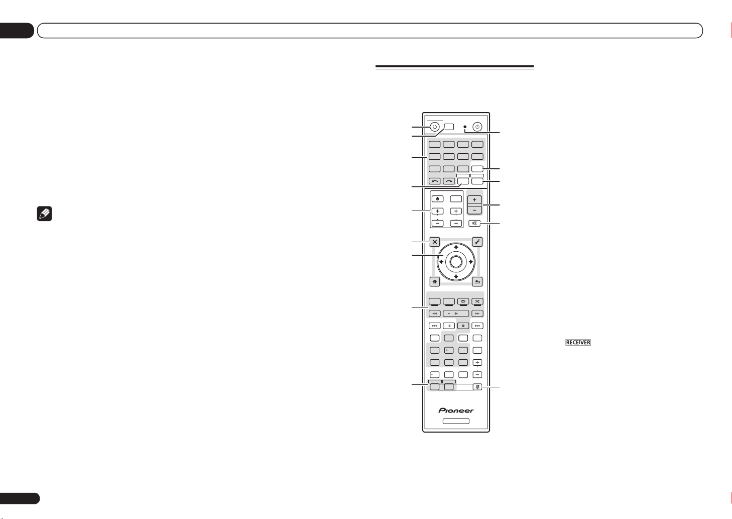
Remote control
This section explains how to operate the remote
control for the receiver.
MULTI
SOURCERECEIVER
1
2,3
4
5
6
7
8
9
10
OPERATION
RCU SETUP
BDR
BD DVD DVR
SAT
HMG
CDTV
USB OPTION
iPod
TUNER
VIDEO
RECEIVER
TV CTRL
SELECT
INPUT
MASTER
VOLUME
INPUT
TV CONTROL
VOL
CH
AUDIO
PARAMETER
TOP MENU
BAND GUIDE
PRESET
PTY
SEARCH
HOME
MENU
iPod CTRL
AUTO / ALC /
DIRECT
HDD DVD
TV
/
DTV MPX PQLS
1 32
SIGNAL SEL
CH LEVEL A.ATT DIMMER
D.ACCESS
/ CLR
ZONE 2 ZONE 3
LIST
TUNE
ENTER
TUNE
PGM
STEREO STANDARD
PHASE
HDMI OUT
MCACC SLEEP
54 6
807 9
RECEIVER
CTRL STATUSTHX
CLASS
ENTER
TOOLS
3
MUTE
PARAMETER
RETURN
MENU
ADV SURR
AUDIO
HDMI
ADPT
VIDEO
T.EDIT
INFO
DISP
LIGHT
11
12
13
14
15
PRESET
CH
16
The remote has been conveniently color-coded
according to component control using the following system:
! White – Receiver control, TV control
! Blue – Other controls (See the Operating
Instructions in CD-ROM for detail.)
1 u RECEIVER
This switches between standby and on for this
receiver.
2 MULTI OPERATION
Use this button to perform multi operations.
3 RCU SETUP
Use to input the preset code when making
remote control settings and to set the remote
control mode.
4 Input function buttons
Press to select control of other components.
Use INPUT SELECT c/ d to select the input
function (page 22).
5 TV CTRL
Set the preset code of your TV’s manufacturer
when controlling the TV.
6 TV CONTROL buttons
These buttons are dedicated to control the TV
assigned to the TV CTRL button.
7 Receiver setting buttons
Press first to access:
! AUDIO PARAMETER – Use to access the
Audio options.
! VIDEO PARAMETER – Use to access the
Video options.
! HOME MENU – Use to access the Home
Menu.
! RETURN – Press to confirm and exit the
current menu screen.
8 i/j/k/l/ENTER
Use the arrow buttons when setting up your
surround sound system and the Audio or Video
options.
En
6
Page 7
Before you start
01
9 Receiver Control buttons
Press first to access:
! AUTO/ALC/DIRECT – Switches between
Auto Surround, Auto Level Control, Optimum
Surround mode and Stream Direct mode.
! STEREO – Press to select stereo playback
mode.
! STANDARD – Press for Standard decoding
and to switch various modes (2 Pro Logic,
Neo:6, etc.) (page 22).
! ADV SURR – Use to switch between the
various surround modes (page 22).
! THX – Press to select a Home THX listening
mode (page 22).
! PHASE CTRL – Press to switch on/off Phase
Control.
Full Band Phase Control can also be
switched.
! STATUS – Press to check selected receiver
settings.
! PQLS – Press to select the PQLS setting.
! HDMI OUT – Switch the HDMI output
terminal.
! SIGNAL SEL – Use to select an input signal.
! MCACC – Press to switch between MCACC
presets.
! SLEEP – Use to put the receiver in sleep
mode and select the amount of time before
sleep.
! CH LEVEL – Press repeatedly to select a
channel, then use k/l to adjust the level.
! A.ATT – Attenuates (lowers) the level of an
analog input signal to prevent distortion.
! DIMMER – Dims or brightens the display.
10 MULTI-ZONE select buttons
Switch to perform operations in ZONE 2 and
ZONE 3.
11 Remote control LED
Lights when a command is sent from the
remote control.
12 OPTION
The preset codes of desired devices can be
registered in the remote control and button
operations can be registered using the learning
mode.
13
Switches the remote to control the receiver
(used to select the white commands).
Switch to perform operations in the main zone.
Also use this button to set up surround sound.
14 MASTER VOLUME +/–
Use to set the listening volume.
15 MUTE
Mutes the sound or restores the sound if it has
been muted (adjusting the volume also restores
the sound).
16 LIGHT
Press to turn on/off the illumination for the
buttons.
The way the buttons light can be selected from
four modes.
En
7
Page 8
02 Connecting your equipment
Connecting your equipment
Connecting your equipment
This receiver provides you with many connection possibilities, but it doesn’t have to be difficult. This chapter explains the kinds of components you can connect to make up your home
theater system.
CAUTION
! Before making or changing the connections,
switch off the power and disconnect the power
cord from the power outlet. Plugging in should
be the final step.
! When making connections, also keep the
power cords of the devices being connected
unplugged from the power outlets.
! Depending on the device being connected
(amplifier, receiver, etc.), the methods of
connection and terminal names may differ
from the explanations in this manual. Also
refer to the operating instructions of the
respective devices.
Determining the speakers’
application
This unit permits you to build various surround
systems, in accordance with the number of
speakers you have.
! Be sure to connect speakers to the front left
and right channels (L and R).
! It is also possible to only connect one of the
surround back speakers (SB) or neither.
! If you have two subwoofers, the second
subwoofer can be connected to the
SUBWOOFER 2 terminal. Connecting two
subwoofers increases the bass sound to
achieve more powerful sound reproduction. In
En
8
this case, the same sound is output from the
two subwoofers.
Choose one from Plans [A] to [E] below.
Important
! The Speaker System setting must be made if
you use any of the connections shown below
other than [A] (see Speaker system setting on
Operating Instructions in CD-ROM).
! Sound does not come through simultaneously
from the front height, front wide, speaker B
and surround back speakers. Output speakers
are different depending on the input signal or
listening mode.
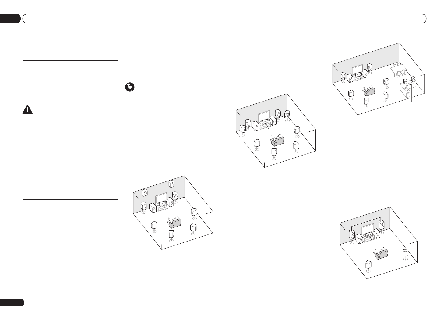
[A] 7.2 channel surround system (Front
height)
*Default setting
! Speaker System setting: Normal(SB/FH)
FHL
L
SW 2
SL
A 7.2 ch surround system connects the left and
right front speakers (L/R), the center speaker
(C), the left and right front height speakers
(FHL/FHR), the left and right surround speakers (SL/SR), the left and right surround back
speakers (SBL/SBR), and the subwoofers (SW 1/
SW 2).
It is not possible to produce sound simultaneously from the front height or front wide speakers and the surround back speakers.
This surround system produces a more true-tolife sound from above.
[B] 7.2 channel surround system (Front
wide)
! Speaker System setting: Normal(SB/FW)
R
SW
1
SBL
FWR
SR
SBR
FWL
L
C
SW 2
SL
L
SW
With these connections you can simultaneously
enjoy 5.2-channel surround sound in the main
zone with stereo playback of the same sound
on the B speakers. The same connections also
allow for 7.2-channel surround sound in the
main zone when not using the B speakers.
R
SW 1
C
2
SL
SBL
SR
SBR
R
L
Speaker B
[D] 5.2 channel surround system & Front
Bi-amping connection (High quality
FHR
speakers shown in [A] with the left and right
front wide speakers (FWL/FWR).
This plan replaces the left and right front height
R
It is not possible to produce sound simultaneously from the front height or front wide speak-
SW
1
C
SR
ers and the surround back speakers.
This surround system produces a true-to-life
surround)
! Speaker System setting: Front Bi-Amp
Bi-amping connection of the front speakers for
high sound quality with 5.2-channel surround
sound.
Front Bi-Amp
sound over a wider area.
SBL
SBR
[C] 7.2 channel surround system & Speaker
B connection
! Speaker System setting: Speaker B
L
SW
2
C
SL
R
SW 1
SR
Page 9
Connecting your equipment
02
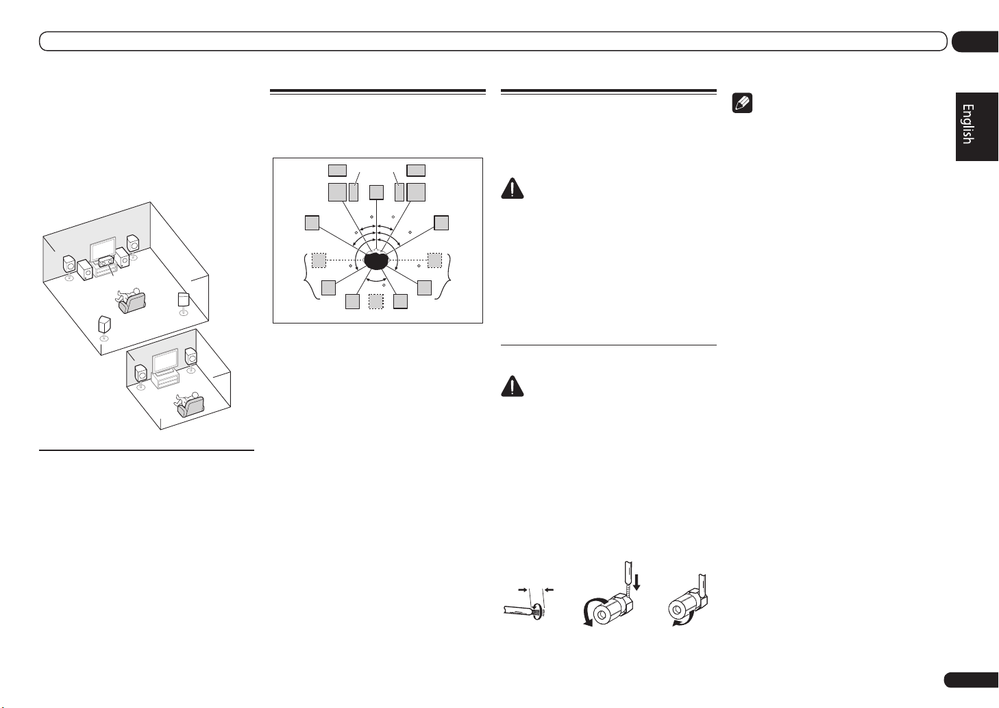
[E] 5.2 channel surround system & ZONE 2
connection (Multi Zone)
! Speaker System setting: ZONE 2
With these connections you can simultaneously
enjoy 5.2-channel surround sound in the main
zone with stereo playback on another component in ZONE 2. (The selection of input devices
is limited.)
R
L
SW 1
C
2
SW
SL
ZONE 2
Main zone
SR
Sub zone
R
L
Other speaker connections
! Your favorite speaker connections can be
selected even if you have fewer than 5.2
speakers (except front left/right speakers).
! When not connecting a subwoofer, connect
speakers with low frequency reproduction
capabilities to the front channel. (The
subwoofer’s low frequency component
is played from the front speakers, so the
speakers could be damaged.)
! After connecting, be sure to conduct the
Full Auto MCACC (speaker environment
setting) procedure. See Automatically
conducting optimum sound tuning (Full Auto
MCACC) on page 19 .
Placing the speakers
Refer to the chart below for placement of the
speakers you intend to connect.
SW
FHL
L
FWL
2 SW 1
C
30 30
60
SL
120 120
60
SBL
SB
! Place the surround speakers at 120º from
the center. If you, (1) use the surround
back speaker, and, (2) don’t use the front
height speakers / front wide speakers, we
recommend placing the surround speaker
right beside you.
! If you intend to connect only one surround
back speaker, place it directly behind you.
! Place the left and right front height speakers
at least one meter directly above the left and
right front speakers.
FHR
R
FWR
60
SR
SBR
Connecting the speakers
Each speaker connection on the receiver comprises a positive (+) and negative (–) terminal.
Make sure to match these up with the terminals
on the speakers themselves.
CAUTION
! These speaker terminals carry HAZARDOUS
LIVE voltage. To prevent the risk of electric
shock when connecting or disconnecting the
speaker cables, disconnect the power cord
before touching any uninsulated parts.
! Make sure that all the bare speaker wire is
twisted together and inserted fully into the
speaker terminal. If any of the bare speaker
wire touches the back panel it may cause the
power to cut off as a safety measure.
Bare wire connections
CAUTION
Make sure that all speakers are securely
installed. This not only improves sound quality,
but also reduces the risk of damage or injury
resulting from speakers being knocked over or
falling in the event of external shocks such as
earthquakes.
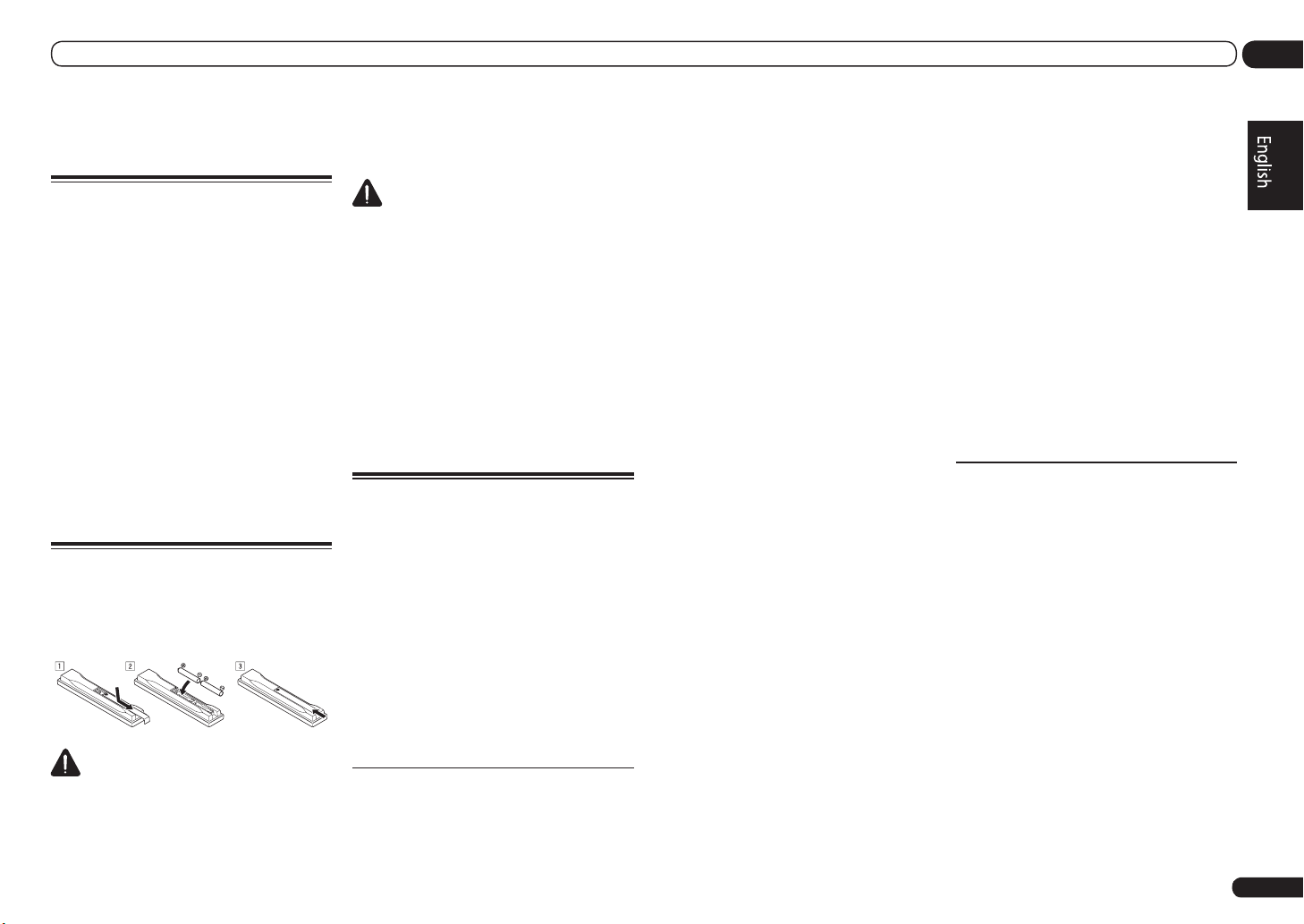
1 Twist exposed wire strands together.
2 Loosen terminal and insert exposed
wire.
3 Tighten terminal.
1 2 3
10 mm
Note
! Please refer to the manual that came with
your speakers for details on how to connect
the other end of the speaker cables to your
speakers.
! Use an RCA cable to connect the subwoofer.
It is not possible to connect using speaker
cables.
! If you have two subwoofers, the second
subwoofer can be connected to the
SUBWOOFER 2 terminal. Connecting two
subwoofers increases the bass sound to
achieve more powerful sound reproduction. In
this case, the same sound is output from the
two subwoofers.
En
9
Page 10
02 Connecting your equipment
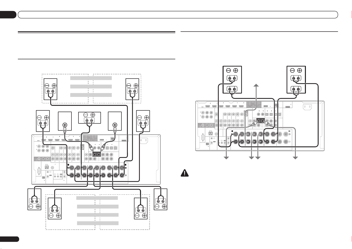
Installing your speaker system
At the very least, front left and right speakers only are necessary. Note that your main surround
speakers should always be connected as a pair, but you can connect just one surround back
speaker if you like (it must be connected to the left surround back terminal).
Standard surround connection
The front height terminals can also be used for the front wide and Speaker B speakers.
Front right
HDMI
ASSIGNABLE
1 6
ASSIGNABLE
Y PBP
1
IN
(
)
DVD
2
IN
(
DVR/
)
BDR
MONITOR
OUT
RS-232C
(
OUTPUT 5 V
150 mA MAX
Surround right
COMPONENT VIDEO
AM LOOP
EXTENSION
IN1IN
ANTENNA
)
Front height right
Front height setting
Front wide setting
Front wide right
Speaker B - right Speaker B - left
Speaker B setting
Center Subwoofer 2Subwoofer 1
LINE LEVEL
INPUT
R
CONTROL
FM UNBAL 75
IN
OUT
ZONE 2
2
IN
IN
(VIDEO)
ZONE 3
OUT
IR
1IN2
(OUTPUT 12 V
TOTAL 150 mA MAX)
12 V TRIGGER
4
BD IN
TV/SAT VIDEO
DVD
IN IN IN IN
SPEAKERS
OUT
6
IN5IN
(DVD)
(DVR/BDR)
MONITOR
OUT
VIDEO
CD
DVR/BDR
IN
OUTOUT
AUDIO
FRONT CENTER
R L R L
A
1
2
OUT 1
(CONTROL)
COAXIAL
FRONT
The surround back terminals can also be used for ZONE 2.
Not connected Not connected
Not connected Surround back
Surround back right Surround back left
ZONE 2 - Right ZONE 2 - Left
5.2 ch surround setting
6.2 ch surround setting
7.2 ch surround setting
ZONE 2 setting
DC OUTPUT
for WIRELESS LAN
OUT 2
ASSIGNABLE ASSIGNABLE
OPTICAL
2
IN1IN2IN3OUT
IN1IN
(CD)(
)
DVD
SUBWOOFER
SURROUND SURR BACK
1 2
CENTER
SURROUND
R L
Front height left
Front wide left
LINE LEVEL
INPUT
LAN
(
OUTPUT
(
10/100
5 V
)
0.6 A MAX
(
)
(
)
DVR/BDR)(TV/SAT
VIDEO
FH / FW
PRE OUT
(
)
Single
L
R
(
)
SURROUND BACK
FRONT HEIGHT / FRONT WIDE /
Single
R L
ADAPTER PORT
)
(
OUTPUT 5 V
0.1 A MAX
Front left
AC IN
)
B
Surround left
Bi-amping your speakers
Bi-amping is when you connect the high frequency driver and low frequency driver of your speakers
to different amplifiers for better crossover performance. Your speakers must be bi-ampable to do
this (having separate terminals for high and low) and the sound improvement will depend on the
kind of speakers you’re using.
LAN
(
)
10/100
)
PRE OUT
L
R
)
FRONT HEIGHT / FRONT WIDE /
R L
ADAPTER PORT
(
OUTPUT 5 V
0.1 A MAX
Front left
High
Low
)
B
AC IN
Bi-amp compatible
speaker
Front right
Bi-amp compatible
speaker
IN1IN
HDMI
ASSIGNABLE
1 6
ASSIGNABLE
COMPONENT VIDEO
Y PBP
1
IN
(
)
DVD
2
IN
(
DVR/
)
BDR
MONITOR
OUT
ANTENNA
RS-232C
AM LOOP
(
OUTPUT 5 V
)
150 mA MAX
EXTENSION
R
FM UNBAL 75
IN
OUT
CONTROL
Subwoofer 1 Subwoofer 2
2
ZONE 2
ZONE 3
OUT
1IN2
IN
High
Low
4
IN
IN5IN
(DVD)
(VIDEO)
TV/SAT VIDEO
DVD
IN IN IN IN
SPEAKERS
IR
OUT
(OUTPUT 12 V
TOTAL 150 mA MAX)
12 V TRIGGER
(DVR/BDR)
BD IN
DVR/BDR
OUTOUT
FRONT CENTER
R L R L
A
1
2
Surround right Surround left
Center
6
OUT 1
DC OUTPUT
for WIRELESS LAN
OUT 2
(CONTROL)
COAXIAL
MONITOR
OUT
VIDEO
CD
IN
FRONT
AUDIO
ASSIGNABLE ASSIGNABLE
OPTICAL
2
IN1IN2IN3OUT
IN1IN
(CD)(
)
DVD
SUBWOOFER
SURROUND SURR BACK
1 2
CENTER
SURROUND
R L
(
OUTPUT
5 V
0.6 A MAX
(
)
DVR/BDR)(TV/SAT
SURROUND BACK
)
(
VIDEO
FH / FW
(
)
Single
(
Single
CAUTION
! Most speakers with both High and Low terminals have two metal plates that connect the High
to the Low terminals. These must be removed when you are bi-amping the speakers or you could
severely damage the amplifier. See your speaker manual for more information.
! If your speakers have a removable crossover network, make sure you do not remove it for bi-amping.
Doing so may damage your speakers.
10
En
Page 11
Connecting your equipment
02
Bi-wiring your speakers
Your speakers can also be bi-wired if they support bi-amping.
! With these connections, the Speaker System
setting makes no difference.
CAUTION
! Don’t connect different speakers from the
same terminal in this way.
! When bi-wiring as well, heed the cautions for
bi-amping shown above.
% To bi-wire a speaker, connect two
speaker cords to the speaker terminal on
the receiver.
Selecting the Speaker system
The front height terminals can be used for front
wide and Speaker B connections, in addition to
for the front height speakers. Also, the surround
back terminals can be used for bi-amping and
ZONE 2 connections, in addition to for the surround back speakers. Make this setting according to the application.
Front height setup
*Default setting
1 Connect a pair of speakers to the front
height speaker terminals.
See Standard surround connection on page 10 .
2 If necessary, select ‘Normal(SB/FH)’
from the Speaker System menu.
See Speaker system setting on Operating
Instructions in CD-ROM to do this.
Front wide setup
1 Connect a pair of speakers to the front
height speaker terminals.
See Standard surround connection on page 10 .
2 Select ‘Normal(SB/FW)’ from the
Speaker System menu.
See Speaker system setting on Operating
Instructions in CD-ROM to do this.
Speaker B setup
You can listen to stereo playback in another
room.
1 Connect a pair of speakers to the front
height speaker terminals.
See Standard surround connection on page 10 .
2 Select ‘Speaker B’ from the
Speaker System menu.
See Speaker system setting on Operating
Instructions in CD-ROM to do this.
Bi-Amping setup
Bi-amping connection of the front speakers for
high sound quality with 5.2-channel surround
sound.
1 Connect bi-amp compatible speakers
to the front and surround back speaker
terminals.
See Bi-amping your speakers on page 10 .
2 Select ‘Front Bi-Amp’ from the
Speaker System menu.
See Speaker system setting on Operating
Instructions in CD-ROM to do this.
ZONE 2 setup
With these connections you can simultaneously
enjoy 5.2-channel surround sound in the main
zone with stereo playback on another component in ZONE 2.
1 Connect a pair of speakers to the
surround back speaker terminals.
See Standard surround connection on page 10 .
2 Select ‘ZONE 2’ from the
Speaker System menu.
See Speaker system setting on Operating
Instructions in CD-ROM to do this.
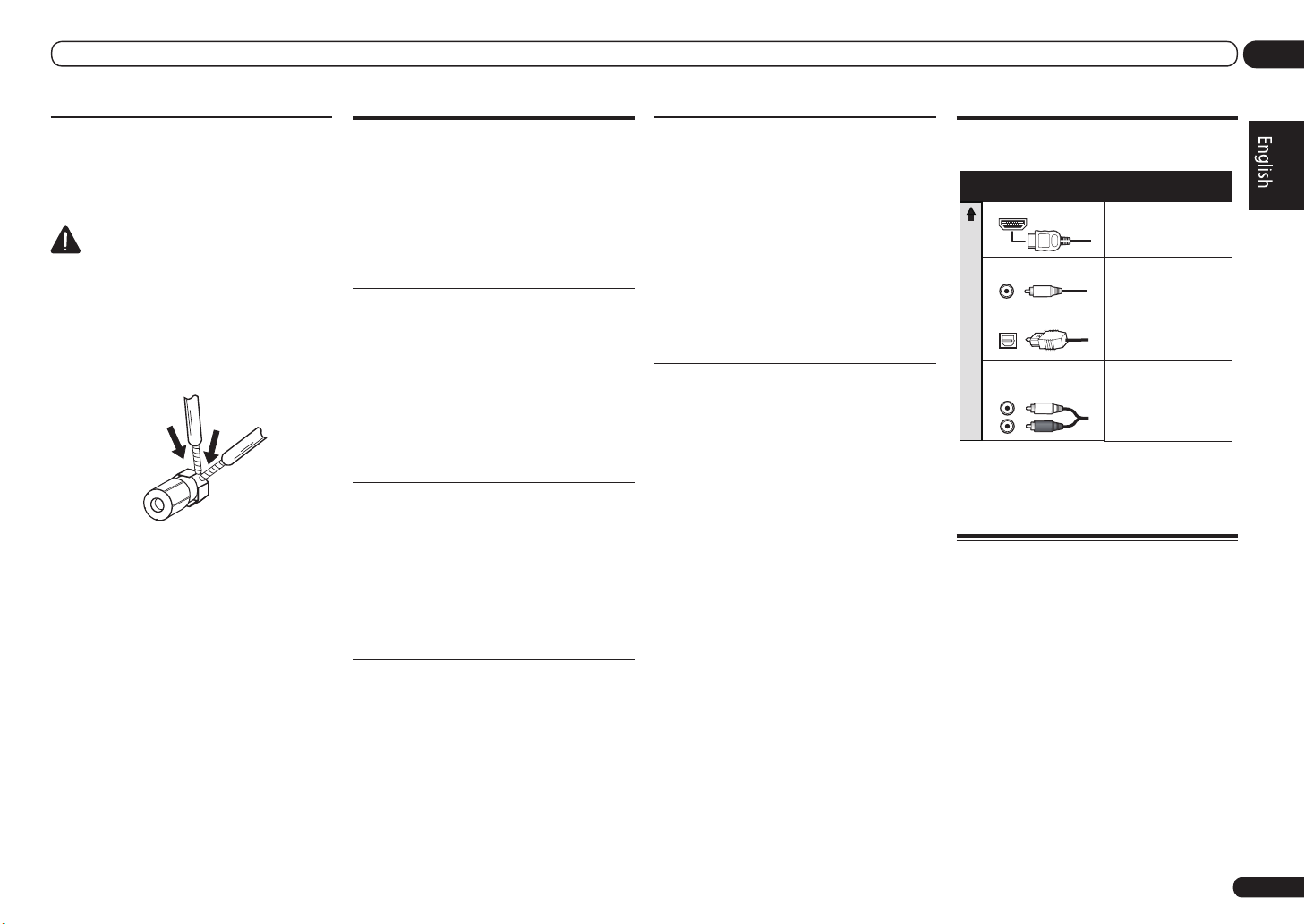
About the audio connection
Types of cables and
terminals
HDMI HD audio
Digital (Coaxial) Conventional digital audio
Digital (Optical)
Sound signal priority
RCA (Analog)
(White/Red)
! With an HDMI cable, video and audio signals
can be transferred in high quality over a single
cable.
Transferable audio
signals
Conventional analog audio
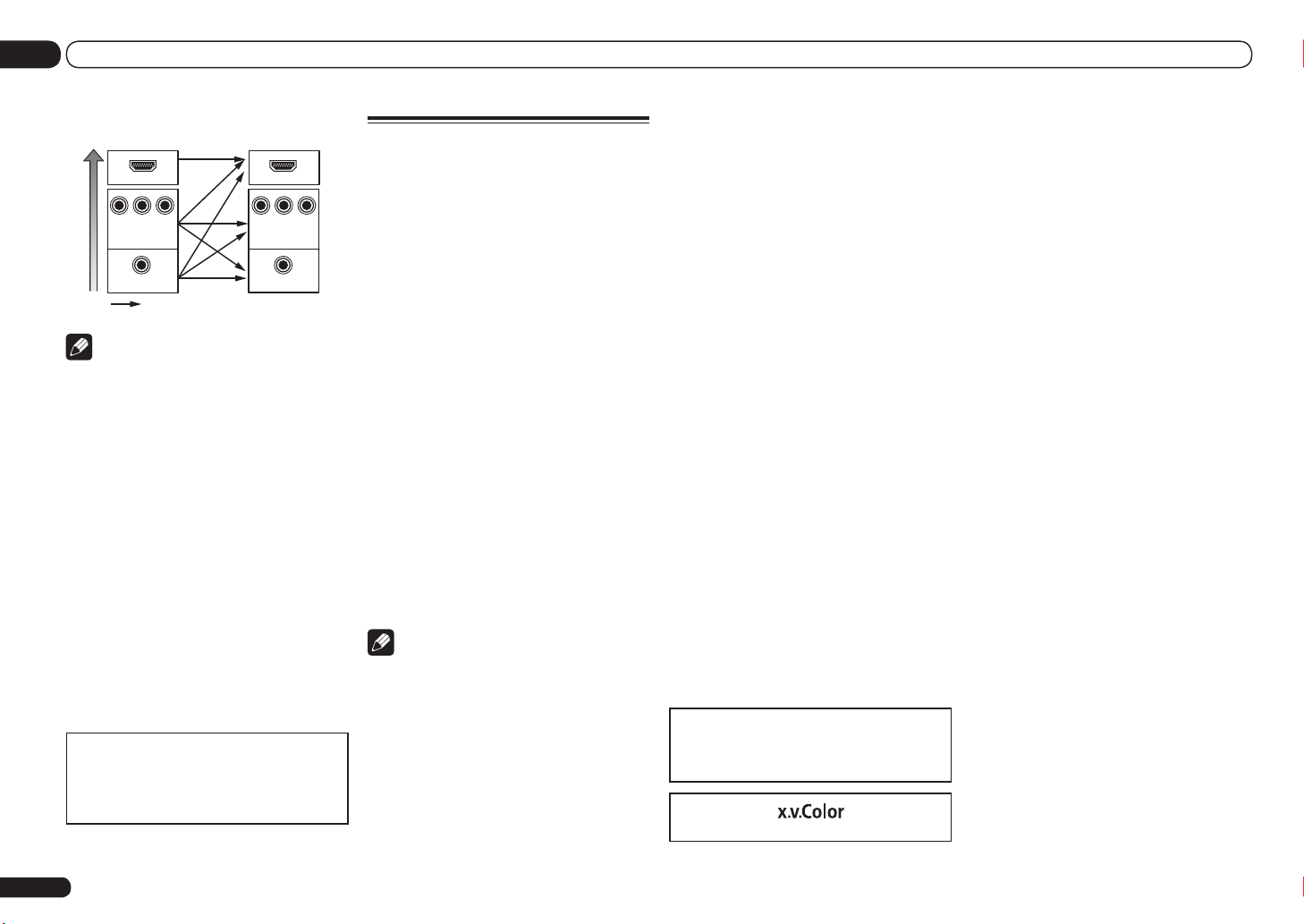
About the video converter
The video converter ensures that all video
sources are output through all of the MONITOR
VIDEO OUT jacks. The only exception is HDMI:
since this resolution cannot be downsampled,
you must connect your monitor/TV to the
receiver’s HDMI output when connecting this
video source.
If several video components are assigned to the
same input function (see The Input Setup menu
on Operating Instructions in CD-ROM), the
converter gives priority to HDMI, component,
then composite (in that order).
En
11
Page 12
02 Connecting your equipment
Terminal for connection with
source device
HDMI IN HDMI OUT
Y PBP
High picture quality
R
COMPONENT
VIDEO IN
VIDEO IN
Video signals can be output
Terminal for connection
with TV monitor
B
P
Y
P
MONITOR OUT
VIDEO
MONITOR OUT
R
COMPONENT VIDEO
Note
! If the video signal does not appear on your
TV, try adjusting the resolution settings on
your component or display. Note that some
components (such as video game units) have
resolutions that may not be converted. In this
case, try switching Digital Video Conversion
(in Setting the Video options on Operating
Instructions in CD-ROM) OFF.
! The signal input resolutions that can be
converted from the component video input
for the HDMI output are 480i/576i, 480p/576p,
720p and 1080i. 1080p signals cannot be
converted.
! Only signals with an input resolution
of 480i/576i can be converted from the
component video input for the composite
MONITOR OUT terminals.
! For optimal video performance, THX
recommends switching Digital Video
Conversion (in Setting the Video options on
Operating Instructions in CD-ROM) OFF.
This item incorporates copy protection technology that is protected by U.S. patents and other
intellectual property rights of Rovi Corporation.
Reverse engineering and disassembly are
prohibited.
About HDMI
The HDMI connection transfers uncompressed
digital video, as well as almost every kind of
digital audio.
This receiver incorporates High-Definition
Multimedia Interface (HDMI®) technology.
This receiver supports the functions described
below through HDMI connections.
! Digital transfer of uncompressed video
(contents protected by HDCP (1080p/24,
1080p/60, etc.))
! 3D signal transfer
! Deep Color signal transfer
! x.v.Color signal transfer
! ARC (Audio Return Channel)
! Input of multi-channel linear PCM digital
audio signals (192 kHz or less) for up to 8
channels
! Input of the following digital audio formats:
— Dolby Digital, Dolby Digital Plus, DTS, High
bitrate audio (Dolby TrueHD, DTS-HD Master
Audio, DTS-HD High Resolution Audio),
DVD-Audio, CD, SACD (DSD signal), Video
CD, Super VCD
! Synchronized operation with components
using the Control with HDMI function (see
Control with HDMI function on Operating
Instructions in CD-ROM)
Note
! An HDMI connection can only be made
with DVI-equipped components compatible
with both DVI and High Bandwidth Digital
Content Protection (HDCP). If you choose to
connect to a DVI connector, you will need a
separate adaptor (DVIdHDMI) to do so. A DVI
connection, however, does not support audio
signals. Consult your local audio dealer for
more information.
! If you connect a component that
is not compatible with HDCP, an
HDCP ERROR message is displayed on the
front panel display. Some components that
are compatible with HDCP still cause this
message to be displayed, but so long as there
is no problem with displaying video this is not
a malfunction.
! Depending on the component you have
connected, using a DVI connection may result
in unreliable signal transfers.
! This receiver supports SACD, Dolby Digital
Plus, Dolby TrueHD and DTS-HD Master
Audio. To take advantage of these formats,
however, make sure that the component
connected to this receiver also supports the
corresponding format.
! Use a High Speed HDMI® cable. If an HDMI
cable other than a High Speed HDMI® cable is
used, it may not work properly.
! When an HDMI cable with a built-in equalizer
is connected, it may not operate properly.
! Signal transfer is only possible when
connected to a compatible component.
! HDMI format digital audio transmissions
require a longer time to be recognized. Due to
this, interruption in the audio may occur when
switching between audio formats or beginning
playback.
! Turning on/off the device connected to this
unit’s HDMI OUT terminal during playback,
or disconnecting/connecting the HDMI
cable during playback, may cause noise or
interrupted audio.
HDMI, the HDMI logo, and High-Definition
Multimedia Interface are trademarks or registered trademarks of HDMI Licensing LLC in the
United States and other countries.
“x.v.Color” and are trademarks of Sony Corporation.
12
En
Page 13
Connecting your equipment
U
02
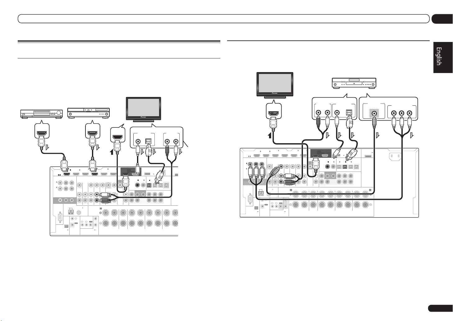
Connecting your TV and playback components
Connecting using HDMI
If you have an HDMI or DVI (with HDCP) equipped component (Blu-ray Disc player (BD), etc.), you
can connect it to this receiver using a commercially available HDMI cable.
If the TV and playback components support the Control with HDMI feature, the convenient Control with
HDMI functions can be used (see Control with HDMI function on Operating Instructions in CD-ROM).
MONITOR
ASSIGNABLE
IN
(
IN
(
DVR/
BDR
OUT
ASSIGNABLE
DVD
HDMI
1
)
2
)
RS-232C
1 6
COMPONENT VIDEO
Y PBP
AM LOOP
(
OUTPUT 5 V
150 mA MAX
EXTENSION
HDMI/DVI-compatible
Blu-ray Disc player
4
IN
2
IN1IN
(VIDEO)
R
DVD
ZONE 2
ZONE 3
IN IN IN IN
OUT
ANTENNA
FM UNBAL 75
SPEAKERS
IR
IN
OUT
1IN2
IN
OUT
(OUTPUT 12 V
CONTROL
)
TOTAL 150 mA MAX)
12 V TRIGGER
HDMI IN
6
IN5IN
(DVD)
(DVR/BDR)
BD IN
MONITOR
OUT
VIDEO
DVR/BDR
OUTOUT
AUDIO
FRONT CENTER
CD
IN
TV/SAT VIDEO
R L R LRR
A
1
2
COAXIAL OPTICAL
OUT 1
OUT 2
(CONTROL)
COAXIAL
ASSIGNABLE ASSIGNABLE
IN1IN
DVD
SUBWOOFER
FRONT
1 2
CENTER
SURROUND
DIGITAL OUT
for WIRELESS LAN
(CD)(
)
Select one
DC OUTPUT
(
OUTPUT
5 V
0.6 A MAX
OPTICAL
2
IN1IN2IN3OUT
(
)
DVR/BDR)(TV/SAT
SURROUND SURR BACK
SURROUND BACK
HDMI/DVI-compatible
monitor
AUDIO OUT
R L
ANALOG
ADAPTE
(
OUTP
LAN
0.1 A
(
)
10/100
)
(
)
VIDEO
FH / FW
PRE OUT
(
)
Single
L
R
(
)
FRONT HEIGHT / FRONT WIDE
Single
L
This connection is
required in order to
listen to the sound
of the TV over the
receiver.
Other HDMI/DVIequipped component
HDMI OUT HDMI OUT
! When connecting to an HDMI/DVI-compatible monitor using the HDMI OUT 2 terminal, switch
the HDMI output setting to HDMI OUT 2 or HDMI OUT ALL. See Switching the HDMI output on
Operating Instructions in CD-ROM.
! For input components, connections other than HDMI connections are also possible (see
Connecting your DVD player with no HDMI output on page 13 ).
! If you want to listen to the sound of the TV over the receiver, connect the receiver and TV with audio
cables.
— When the TV and receiver are connected by HDMI connections, if the TV supports the HDMI ARC
(Audio Return Channel) function, the sound of the TV is input to the receiver via the HDMI OUT
terminal, so there is no need to connect an audio cable. In this case, set TV Audio at HDMI Setup
to via HDMI (see HDMI Setup on Operating Instructions in CD-ROM).
Connecting your DVD player with no HDMI output
This diagram shows connections of a TV (with HDMI input) and DVD player (or other playback component with no HDMI output) to the receiver.
HDMI/DVI-compatible monitor
AUDIO OUT
R
(DVR/BDR)
ANALOG
6
OUT 1
(CONTROL)
COAXIAL
MONITOR
OUT
VIDEO
CD
IN
FRONT
AUDIO
SURROUND
ASSIGNABLE
MONITOR
IN
(
IN
(
DVR/
BDR
OUT
DVD
HDMI
ASSIGNABLE
1
)
2
)
RS-232C
1 6
COMPONENT VIDEO
Y PBP
AM LOOP
(
OUTPUT 5 V
150 mA MAX
EXTENSION
IN1IN
R
ANTENNA
CONTROL
)
FM UNBAL 75
IN
OUT
ZONE 2
HDMI IN
2
IN
ZONE 3
1IN2
4
IN
(VIDEO)
OUT
IR
(OUTPUT 12 V
TOTAL 150 mA MAX)
12 V TRIGGER
IN5IN
(DVD)
BD IN
TV/SAT VIDEO
DVD
SPEAKERS
OUT
DVR/BDR
IN IN IN IN
OUTOUT
FRONT CENTER
R L R L
A
1
2
! If you want to listen to the sound of the TV over the receiver, connect the receiver and TV with audio
cables (page 13).
— When the TV and receiver are connected by HDMI connections, if the TV supports the HDMI ARC
(Audio Return Channel) function, the sound of the TV is input to the receiver via the HDMI OUT
terminal, so there is no need to connect an audio cable. In this case, set TV Audio at HDMI Setup
to via HDMI (see HDMI Setup on Operating Instructions in CD-ROM).
! If you use an optical digital audio cable, you’ll need to tell the receiver which digital input you
connected the player to (see The Input Setup menu on Operating Instructions in CD-ROM).
DVD player, etc.
Select one Select one
DIGITAL OUT
L
COAXIAL OPTICAL
DC OUTPUT
for WIRELESS LAN
OUT 2
(
OUTPUT
5 V
)
0.6 A MAX
OPTICAL
ASSIGNABLE ASSIGNABLE
2
IN1IN2IN3OUT
IN1IN
(CD)(
)
(
)
DVR/BDR)(TV/SAT
SURROUND SURR BACK
SURROUND BACK
R
(
VIDEO
FH / FW
(
)
Single
(
Single
L
DVD
SUBWOOFER
1 2
CENTER
LAN
(
)
10/100
)
PRE OUT
L
R
)
FRONT HEIGHT / FRONT WIDE /
R L
ADAPTER PORT
(
OUTPUT 5 V
0.1 A MAX
VIDEO OUT
VIDEO
)
B
AC IN
COMPONENT VIDEO OUT
PR
P
B
Y
En
13
Page 14
02 Connecting your equipment
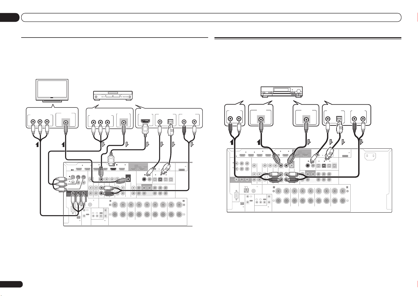
Connecting your TV with no HDMI input
This diagram shows connections of a TV (with no HDMI input) and DVD player (or other playback
component) to the receiver.
! With these connections, the picture is not output to the TV even if the DVD player is connected with
an HDMI cable. Connect the receiver and TV using the same type of video cable as used to connect
the receiver and player.
DVD player, etc.
TV
COMPONENT VIDEO IN
P
R
P
B
Select one
VIDEO IN
VIDEO
Y
IN1IN
HDMI
ASSIGNABLE
1 6
ASSIGNABLE
COMPONENT VIDEO
Y PBP
R
1
IN
(
)
DVD
2
IN
(
DVR/
)
BDR
MONITOR
OUT
ANTENNA
RS-232C
FM UNBAL 75
AM LOOP
IN
OUT
(
OUTPUT 5 V
CONTROL
)
150 mA MAX
EXTENSION
! Connect using an HDMI cable to listen to HD audio on the receiver. Do not use an HDMI cable
to input video signals.Depending on the video component, it may not be possible to output
signals connected by HDMI and other methods simultaneously, and it may be necessary to make
output settings. Please refer to the operating instructions supplied with your component for more
information.
! If you want to listen to the sound of the TV over the receiver, connect the receiver and TV with audio
cables (page 13).
! If you use an optical digital audio cable, you’ll need to tell the receiver which digital input you
connected the player to (see The Input Setup menu on Operating Instructions in CD-ROM).
En
14
Select one Select one
COMPONENT VIDEO OUT
PR
2
ZONE 2
ZONE 3
OUT
1IN2
IN
P
B
Y
4
IN
(VIDEO)
BD IN
TV/SAT VIDEO
DVD
IN IN IN IN
SPEAKERS
IR
1
OUT
2
(OUTPUT 12 V
TOTAL 150 mA MAX)
12 V TRIGGER
A
VIDEO OUT
VIDEO
IN5IN
(DVD)
(DVR/BDR)
DVR/BDR
OUTOUT
FRONT CENTER
R L R L
HDMI OUT
6
OUT 1
(CONTROL)
COAXIAL
MONITOR
OUT
VIDEO
CD
IN
FRONT
AUDIO
SURROUND
COAXIAL OPTICAL
DC OUTPUT
for WIRELESS LAN
OUT 2
(
OUTPUT
5 V
0.6 A MAX
OPTICAL
ASSIGNABLE ASSIGNABLE
2
IN1IN2IN3OUT
IN1IN
(CD)(
)
(
)
DVD
DVR/BDR)(TV/SAT
SUBWOOFER
SURROUND SURR BACK
1 2
CENTER
SURROUND BACK
R
DIGITAL OUT
)
(
VIDEO
FH / FW
(
)
Single
(
Single
L
ADAPTER PORT
LAN
(
)
10/100
)
PRE OUT
L
R
)
FRONT HEIGHT / FRONT WIDE /
R L
(
OUTPUT 5 V
0.1 A MAX
AUDIO OUT
R
ANALOG
)
B
Connecting an HDD/DVD recorder, BD recorder and other video
sources
This receiver has two sets of audio/video inputs and outputs suitable for connecting analog or digital video devices, including HDD/DVD recorders and BD recorders.
When you set up the receiver you’ll need to tell the receiver which input you connected the recorder
to (see also The Input Setup menu on Operating Instructions in CD-ROM).
HDD/DVD recorder, BD recorder, etc.
IN1IN
R
ANTENNA
CONTROL
)
ZONE 2
FM UNBAL 75
IN
OUT
2
ZONE 3
1IN2
IN
VIDEO IN
VIDEO
4
IN
(VIDEO)
OUT
IR
(OUTPUT 12 V
TOTAL 150 mA MAX)
12 V TRIGGER
IN5IN
BD IN
(DVD)
TV/SAT VIDEO
DVD
SPEAKERS
OUT
DVR/BDR
IN IN IN IN
OUTOUT
FRONT CENTER
R L R L
A
1
2
AUDIO IN
L
R
L
ANALOG
ASSIGNABLE
IN
(
DVD
IN
(
DVR/
BDR
MONITOR
OUT
HDMI
ASSIGNABLE
1 6
Y PBP
1
)
2
)
RS-232C
(
OUTPUT 5 V
150 mA MAX
COMPONENT VIDEO
AM LOOP
EXTENSION
(DVR/BDR)
VIDEO OUT
VIDEO
6
OUT 1
DC OUTPUT
for WIRELESS LAN
OUT 2
(CONTROL)
COAXIAL
OPTICAL
ASSIGNABLE ASSIGNABLE
2
IN1IN2IN3OUT
AUDIO
IN1IN
(CD)(
VIDEO
)
DVD
CD
IN
SUBWOOFER
FRONT
SURROUND SURR BACK
1 2
CENTER
SURROUND
R
OUT
MONITOR
! In order to record, you must connect the analog audio cables (the digital connection is for playback
only).
! If your HDD/DVD recorder, BD recorder, etc., is equipped with an HDMI output terminal, we
recommend connecting it to the receiver’s HDMI DVR/BDR IN terminal. When doing so, also
connect the receiver and TV by HDMI (see Connecting using HDMI on page 13 ).
(
OUTPUT
5 V
0.6 A MAX
(
)
DVR/BDR)(TV/SAT
SURROUND BACK
Select one
DIGITAL OUT
COAXIAL OPTICAL
LAN
(
)
10/100
)
(
)
VIDEO
FH / FW
PRE OUT
(
)
Single
L
R
(
)
FRONT HEIGHT / FRONT WIDE /
Single
L
R L
ADAPTER PORT
(
OUTPUT 5 V
0.1 A MAX
AUDIO OUT
R L
ANALOG
AC IN
)
B
Page 15
Connecting your equipment
02
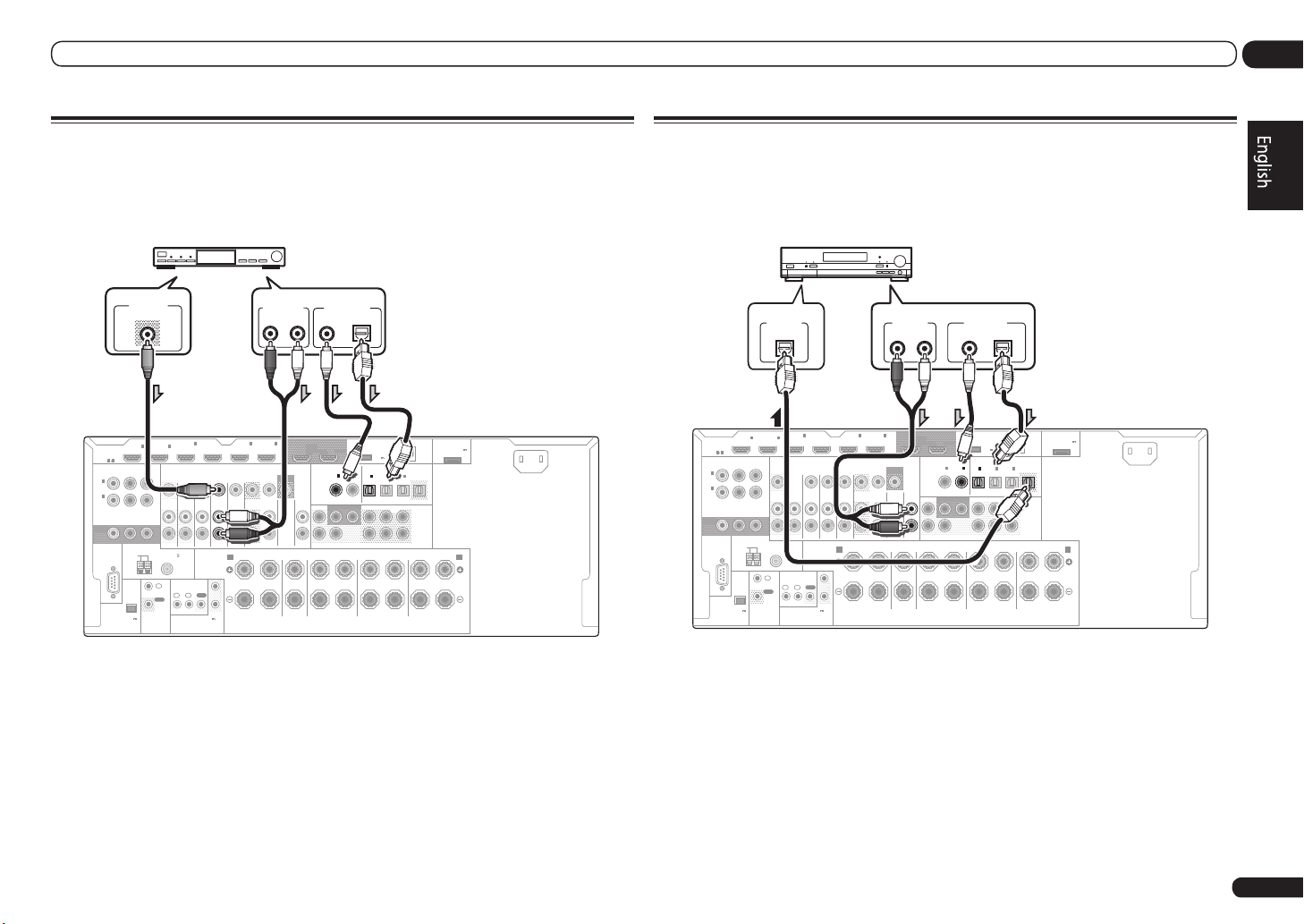
Connecting a satellite/cable receiver or other set-top box
Satellite and cable receivers, and terrestrial digital TV tuners are all examples of so-called ‘set-top
boxes’.
When you set up the receiver you’ll need to tell the receiver which input you connected the set-top
box to (see The Input Setup menu on Operating Instructions in CD-ROM).
STB
VIDEO OUT
VIDEO
4
IN
2
ASSIGNABLE
MONITOR
IN
(
DVD
IN
(
DVR/
BDR
OUT
HDMI
ASSIGNABLE
1
)
2
)
RS-232C
1 6
COMPONENT VIDEO
Y PBP
AM LOOP
(
OUTPUT 5 V
150 mA MAX
EXTENSION
IN1IN
R
ANTENNA
CONTROL
)
ZONE 2
FM UNBAL 75
IN
OUT
(VIDEO)
DVD
ZONE 3
OUT
IN IN IN IN
SPEAKERS
IR
OUT
1IN2
IN
(OUTPUT 12 V
TOTAL 150 mA MAX)
12 V TRIGGER
BD IN
TV/SAT VIDEO
1
2
! If your set-top box is equipped with an HDMI output terminal, we recommend connecting it to the
receiver’s HDMI IN 1 or IN 2 terminal. When doing so, also connect the receiver and TV by HDMI
(see Connecting using HDMI on page 13 ).
Select one
AUDIO OUT
R
L
ANALOG
COAXIAL OPTICAL
6
IN5IN
(DVD)
OUTOUT
FRONT CENTER
R L R L
A
DVR/BDR
(DVR/BDR)
MONITOR
AUDIO
OUT 1
(CONTROL)
COAXIAL
OUT
VIDEO
CD
IN
FRONT
DIGITAL OUT
DC OUTPUT
for WIRELESS LAN
OUT 2
OPTICAL
ASSIGNABLE ASSIGNABLE
2
IN1IN2IN3OUT
IN1IN
(CD)(
)
DVD
SUBWOOFER
SURROUND SURR BACK
1 2
CENTER
SURROUND BACK
SURROUND
R
ADAPTER PORT
(
OUTPUT 5 V
LAN
(
OUTPUT
(
)
10/100
5 V
)
0.6 A MAX
(
)
(
)
DVR/BDR)(TV/SAT
VIDEO
FH / FW
PRE OUT
(
)
Single
L
R
(
)
FRONT HEIGHT / FRONT WIDE /
Single
L
R L
0.1 A MAX
AC IN
)
B
Connecting other audio components
This receiver has both digital and analog inputs, allowing you to connect audio components for
playback.
When you set up the receiver you’ll need to tell the receiver which input you connected the component to (see also The Input Setup menu on Operating Instructions in CD-ROM).
MD, DAT, etc.
Select one
AUDIO OUT
R L
ANALOG
6
IN5IN
(DVD)
(DVR/BDR)
MONITOR
OUT
VIDEO
CD
DVR/BDR
IN
OUTOUT
AUDIO
FRONT CENTER
R L R L
ASSIGNABLE
MONITOR
IN
(
IN
(
BDR
OUT
ASSIGNABLE
1
DVD
2
DVR/
HDMI
)
)
RS-232C
1 6
COMPONENT VIDEO
Y PBP
AM LOOP
(
OUTPUT 5 V
150 mA MAX
EXTENSION
IN1IN
ANTENNA
)
R
CONTROL
DIGITAL IN
ZONE 2
FM UNBAL 75
IN
OUT
OPTICAL
2
ZONE 3
1IN2
IN
IN
OUT
IR
(OUTPUT 12 V
TOTAL 150 mA MAX)
12 V TRIGGER
4
BD IN(VIDEO)
TV/SAT VIDEO
DVD
IN IN IN IN
SPEAKERS
A
1
OUT
2
! If your turntable has line-level outputs (i.e., it has a built-in phono pre-amp), connect it to the CD
inputs instead.
! You can’t hear HDMI audio through this receiver’s digital out jack.
OUT 1
OUT 2
(CONTROL)
COAXIAL
ASSIGNABLE ASSIGNABLE
IN1IN
DVD
SUBWOOFER
FRONT
1 2
CENTER
SURROUND
DIGITAL OUT
COAXIAL OPTICAL
DC OUTPUT
for WIRELESS LAN
OPTICAL
2
IN1IN2IN3OUT
(CD)(
)
SURROUND SURR BACK
SURROUND BACK
R
ADAPTER PORT
(
OUTPUT 5 V
LAN
(
OUTPUT
(
)
10/100
5 V
)
0.6 A MAX
(
)
(
)
DVR/BDR)(TV/SAT
VIDEO
FH / FW
PRE OUT
(
)
Single
L
R
(
)
FRONT HEIGHT / FRONT WIDE /
Single
L
R L
0.1 A MAX
AC IN
)
B
En
15
Page 16
RS-232C
ZONE 2
IN IN
OUT
ZONE 3
OUT
TV/SAT VDVD
COMPONENT VIDEO
Y PBP
R
ASSIGNABLE
MONITOR
OUT
(
DVD
)
IN
1
(
DVR/
BDR
)
IN
2
BD IN
EXTENSION
SPEAKERS
A
FM UNBAL 75
AM LOOP
ANTENNA
(
OUTPUT 5 V
150 mA MAX
)
CONTROL
IR
OUT
IN
OUT
IN
1IN2
2
1
12 V TRIGGER
(OUTPUT 12 V
TOTAL 150 mA MAX)
02 Connecting your equipment
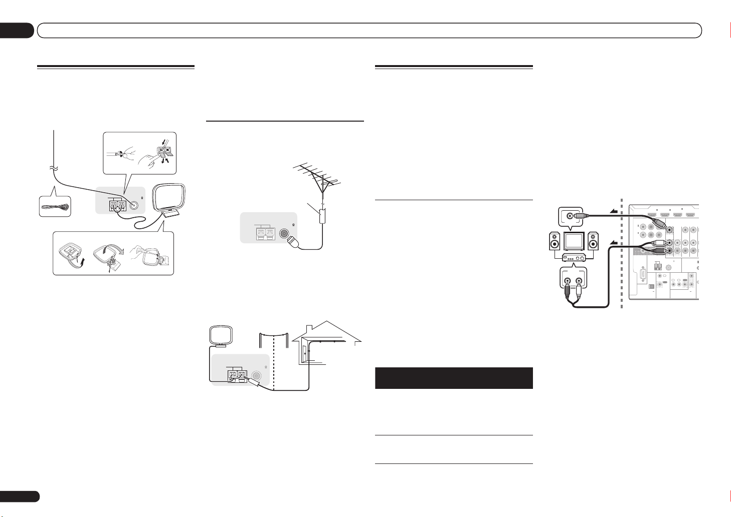
Connecting AM/FM antennas
Connect the AM loop antenna and the FM wire
antenna as shown below. To improve reception
and sound quality, connect external antennas
(see Connecting external antennas on page 16 ).
1
5
a b c
ANTENNA
2
3
FM UNBAL 75 AM LOOP
5 Connect the FM wire antenna into the
FM antenna socket.
For best results, extend the FM antenna fully
and fix to a wall or door frame. Don’t drape
loosely or leave coiled up.
Connecting external antennas
To improve FM reception, connect an external
FM antenna to FM UNBAL 75 W.
4
75 Ω coaxial cable
ANTENNA
FM UNBAL 75 AM LOOP
MULTI-ZONE setup
This receiver can power up to three independent systems in separate rooms after you have
made the proper MULTI-ZONE connections.
Different sources can be playing in three zones
at the same time or, depending on your needs,
the same source can also be used. The main
and sub zones have independent power (the
main zone power can be off while one (or both)
of the sub zones is on) and the sub zones can
be controlled by the remote or front panel
controls.
Making MULTI-ZONE connections
It is possible to make these connections if
you have a separate TV and speakers for your
primary (ZONE 2) sub zone, and a separate TV
terminals, digital input terminals (OPTICAL and
COAXIAL) and the COMPONENT VIDEO input
terminals and output them to ZONE 2.
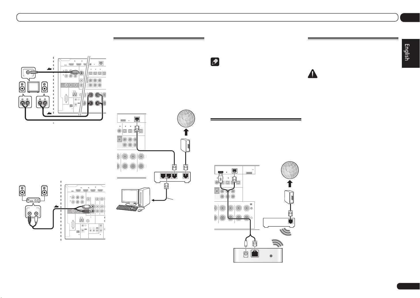
Basic MULTI-ZONE setup (ZONE 2)
1 Connect a separate amplifier to the
AUDIO ZONE 2 OUT jacks on this receiver.
You should have a pair of speakers attached to
the sub zone amplifier as shown in the following illustration.
2 Connect a TV monitor to the VIDEO
ZONE 2 OUT jack on this receiver.
Sub zone (ZONE 2)
VIDEO IN
Main zone
HDMI
ASSIGNABLE
1 6
IN1IN
4
IN
2
(VIDEO)
and a separate amplifier (and speakers) for your
To improve AM reception, connect a 5 m to 6
m length of vinyl-coated wire to the AM LOOP
terminals without disconnecting the supplied
1 Pull off the protective shields of both
AM antenna wires.
2 Push open the tabs, then insert one
wire fully into each terminal, then release
the tabs to secure the AM antenna wires.
3 Fix the AM loop antenna to the
attached stand.
To fix the stand to the antenna, bend in the
AM loop antenna.
For the best possible reception, suspend horizontally outdoors.
Outdoor antenna
Indoor antenna
ANTENNA
FM UNBAL 75 AM LOOP
(vinyl-coated wire)
direction indicated by the arrow (fig. a) then clip
the loop onto the stand (fig. b).
5 m to 6 m
! If you plan to mount the AM antenna to a
wall or other surface, secure the stand with
screws (fig. c) before clipping the loop to the
stand. Make sure the reception is clear.
16
4 Place the AM antenna on a flat
surface and in a direction giving the best
reception.
En
secondary (ZONE 3) sub zone. You will also
need a separate amplifier if you are not using
the MULTI-ZONE setup using speaker terminals
(ZONE 2) on page 16 for your primary sub zone.
There are two primary sub zone setups possible
with this system. Choose whichever works best
for you.
MULTI-ZONE listening options
The following table shows the signals that can
be output to ZONE 2 and ZONE 3:
Sub
Input functions available
Zone
DVD, TV/SAT, DVR/BDR, VIDEO,
ZONE 2
ZONE 3
It is not possible to down-convert the audio
and video input signals from the HDMI input
HOME MEDIA GALLERY, iPod/USB,
CD, TUNER, ADAPTER PORT
(Outputs analog audio, composite
video.)
DVD, TV/SAT, DVR/BDR, VIDEO, CD,
TUNER, ADAPTER PORT
(Outputs analog audio)
AUDIO IN
R L
MULTI-ZONE setup using speaker
terminals (ZONE 2)
You must select ZONE 2 in Speaker system
setting on Operating Instructions in CD-ROM to
use this setup.
1 Connect a pair of speakers to the
surround back speaker terminals.
Page 17
Connecting your equipment
L
R
PRE O
2
TER
SURROUND SURR BACK
FH / FW
(CD)D)
1IN2
(
DVR/BDR)(TV/SAT
)
OPTICAL
ASSIGNABLE
IN1IN2IN3OUT
(
VIDEO
)
DC OUTPUT
for WIRELESS LAN
(
10/10
LAN
(
OUTPUT
5 V
0.6 A MAX
)
SURROUND BACK
LRR L
(
Single
)
(
Single
)
FRONT HE
RS-232C
ZONE 2
OUT
ZONE 3
OUT
COMPONENT VIDEO
Y PBP
R
ASSIGNABLE
MONITOR
OUT
(
DVD
)
IN
1
(
DVR/
BDR
)
IN
2
HDMI
IN1IN
2
ASSIGNABLE
1 6
EXTENSION
FM UNBAL 75
AM LOOP
ANTENNA
(
OUTPUT 5 V
150 mA MAX
)
CONTROL
IR
OUT
IN
IN1IN
(OU
TO
RS-232C
ZONE 2
IN IN
OUT
ZONE 3
OUT
TV/SAT VDVD
COMPONENT VIDEO
Y PBP
R
ASSIGNABLE
MONITOR
OUT
(
DVD
)
IN
1
(
DVR/
BDR
)
IN
2
BD IN
EXTENSION
SPEAKERS
A
FM UNBAL 75
AM LOOP
ANTENNA
(
OUTPUT 5 V
150 mA MAX
)
CONTROL
IR
OUT
IN
OUT
IN
1IN2
2
1
12 V TRIGGER
(OUTPUT 12 V
TOTAL 150 mA MAX)
F
02
2 Connect a TV monitor to the VIDEO
ZONE 2 OUT jack on this receiver.
Sub zone (ZONE 2)
VIDEO IN
Main zone
RL
Secondary MULTI-ZONE setup
(ZONE 3)
% Connect a separate amplifier to the
AUDIO ZONE 3 OUT jacks on this receiver.
You should have a pair of speakers attached to
the sub zone amplifier as shown in the following illustration.
Main zone
Sub zone (ZONE 3)
AUDIO IN
R L
HDMI
ASSIGNABLE
Connecting to the network
through LAN interface
By connecting this receiver to the network via
the LAN terminal, you can listen to Internet
radio stations. To listen to Internet radio stations, you must sign a contract with an ISP
(Internet Service Provider) beforehand.
When connected in this way, you can play audio
files stored on the components on the network,
including your computer, using HOME MEDIA
GALLERY inputs.
DC OUTPUT
for WIRELESS LAN
LE
OPTICAL
2
IN
(CD)
OFER2SURROUND SURR BACK
LRR
(
OUTPUT
5 V
)
0.6 A MAX
ASSIGNABLE
IN1IN2IN3OUT
(
)
(
)
DVR/BDR)(TV/SAT
VIDEO
FH / FW
(
)
Single
(
)
SURROUND BACK
Single
L
LAN
(
10/100
PRE OUT
L
R
FRONT HEIGHT /
)
Internet
Modem
! LAN terminal : Ethernet jack
(10BASE-T/100BASE-TX)
Note
! Refer to the operation manual of the
equipment you have as the connected
equipment and connection method may differ
depending on your Internet environment.
! When using a broadband Internet connection,
a contract with an Internet service provider
is required. For more details, contact your
nearest Internet service provider.
Connecting to a wireless LAN
Wireless connection to the network is possible
through a wireless LAN connection. Use the
AS-WL300 for connection.
! Use only the furnished accessory connecting
cable.
Plugging in the receiver
Only plug in after you have connected all your
components to this receiver, including the
speakers.
CAUTION
! Handle the power cord by the plug part. Do
not pull out the plug by tugging the cord, and
never touch the power cord when your hands
are wet, as this could cause a short circuit or
electric shock. Do not place the unit, a piece of
furniture, or other object on the power cord or
pinch the cord in any other way. Never make
a knot in the cord or tie it with other cables.
The power cords should be routed so that they
are not likely to be stepped on. A damaged
power cord can cause a fire or give you an
electric shock. Check the power cord once in a
while. If you find it damaged, ask your nearest
Pioneer authorized independent service
company for a replacement.
LAN terminal specifications
! Do not use any power cord other than the one
supplied with this unit.
! Do not use the supplied power cord for any
purpose other than that described below.
! The receiver should be disconnected by
removing the mains plug from the wall
socket when not in regular use, e.g., when on
vacation.
! If you have connected speakers with a 6 W
impedance, change the impedance setting
before turning on the power.
! VSX-LX55 only:
Make sure the blue u STANDBY/ON light has
gone out before unplugging.
1 Plug the supplied power cord into the
AC IN socket on the back of the receiver.
)
(
VIDEO
FH / FW
(
)
Single
L
LAN
(
10/100
)
PRE OUT
L
R
(
)
FRONT HEIGHT / FRONT WIDE /
Single
R L
ADAPTER PORT
)
(
OUTPUT 5 V
0.1 A MAX
)
Internet
Modem
B
Router
WAN
DC OUTPUT
for WIRELESS LAN
2
(
OUTPUT
5 V
0.6 A MAX
OPTICAL
LAN
3 2 1
4
IN
2
IN1IN
1 6
(VIDEO)
WAN
Router
LAN cable
(sold separately)
to LAN port
BLE ASSIGNABLE
2
IN1IN2IN3OUT
IN
(CD)
(
)
DVR/BDR)(TV/SAT
OFER2SURROUND SURR BACK
SURROUND BACK
L
R
PC
Connect the LAN terminal on this receiver to
the LAN terminal on your router (with or without the built-in DHCP server function) with a
straight LAN cable (CAT 5 or higher).
Turn on the DHCP server function of your
router. In case your router does not have the
built-in DHCP server function, it is necessary
to set up the network manually. For details, see
Network Setup menu on Operating Instructions
DC 5V WPS
Ethernet
Wireless LAN converter (AS-WL300)
in CD-ROM.
En
17
Page 18

02 Connecting your equipment
2 Plug the other end into a power outlet.
! After this receiver is connected to an AC
outlet, a 2 second to 10 second HDMI
initialization process begins. You cannot
carry out any operations during this process.
The HDMI indicator in the front panel display
blinks during this process, and you can turn
on this receiver once it has stopped blinking.
When you set the Control with HDMI to
OFF, you can skip this process. For details
about the Control with HDMI feature, see
Control with HDMI function on Operating
Instructions in CD-ROM.
18
En
Page 19
Basic Setup
03
Basic Setup
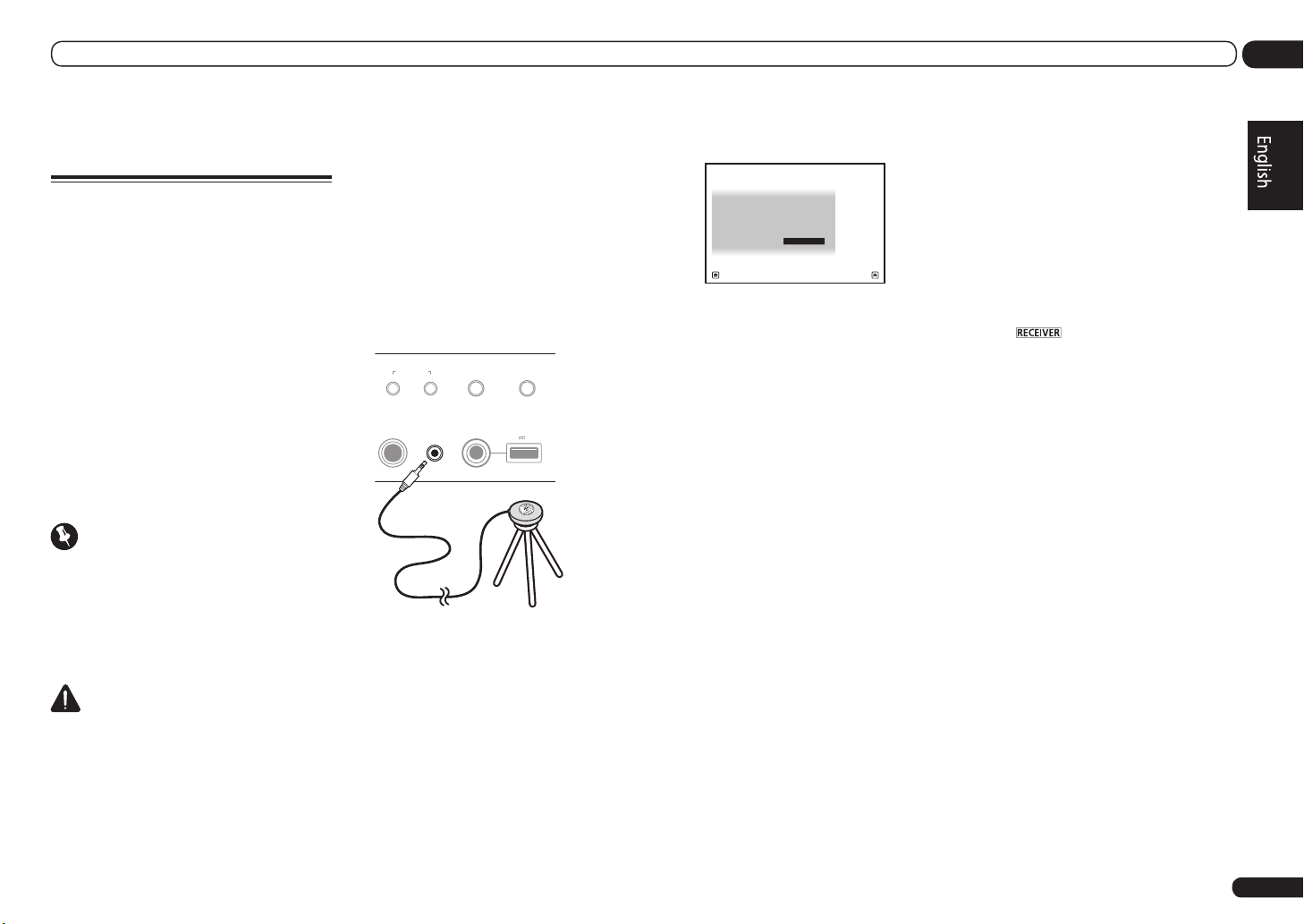
Automatically conducting
optimum sound tuning (Full
Auto MCACC)
The Full Auto MCACC Setup measures the
acoustic characteristics of your listening area,
taking into account ambient noise, speaker
connection and speaker size, and tests for both
channel delay and channel level. After you have
set up the microphone provided with your system, the receiver uses the information from a
series of test tones to optimize the speaker settings and equalization for your particular room.
By performing the Full Auto MCACC Setup
procedure, the frequency-phase characteristics
of the connected speakers are also calibrated.
Once the Full Auto MCACC Setup procedure is
completed, the Full Band Phase Control function is automatically turned on.
Important
! Make sure the microphone and speakers are
not moved during the Full Auto MCACC Setup.
! Using the Full Auto MCACC Setup will
overwrite any existing settings for the MCACC
preset you select.
! Before using the Full Auto MCACC Setup, the
headphones should be disconnected.
CAUTION
! The test tones used in the Full Auto MCACC
Setup are output at high volume.
®
THX
! THX is a trademark of THX Ltd. which is
registered in some jurisdictions. All rights
reserved.
1 Press u RECEIVER to switch on the
receiver and your TV.
Make sure that the TV’s video input is set to this
receiver.
2 Connect the microphone to the MCACC
SETUP MIC jack on the front panel.
Push down on the lower portion of the front
panel door to access the MCACC SETUP MIC
jack.
AUTO SURR/ALC/
MCACC
SETUP MIC
iPod iPhone iPad
DIRECT CONTROL
STREAM DIRE CT
5V 2.1 A
iPod iPhone iPad
USB
Microphone
Tripod
MULTI-ZONE
CONTROL ON/OFF
PHONES
Make sure there are no obstacles between the
speakers and the microphone.
If you have a tripod, use it to place the microphone so that it’s about ear level at your
normal listening position. If you do not have
a tripod, use some other object to install the
microphone.
Install the microphone on a stable floor.
Placing the microphone on any of the following
surfaces may make accurate measurement
impossible:
! Sofas or other soft surfaces.
! High places such as tabletops and sofa tops.
The Full Auto MCACC display appears once the
microphone is connected.
1a.Full Auto MCACC
A/V RECEIVER
Speaker System : Normal(SB/FH
EQ Type : SYMMETRY
MCACC : M1.MEMORY 1
THX Speaker : NO
START
Exit Retu rn
)
! If you leave the GUI screen for over five
minutes, the screen saver will appear.
3 Select the parameters you want to set.
! When data measurement is taken, the
reverb characteristics data (both before- and
after-calibration) that this receiver had been
storing will be overwritten.
! When measurement is taken of the reverb
characteristics data other than SYMMETRY,
the data are not measured after the
correction. If you will need to measure after
correcting data, take the measurement
using the EQ Professional menu in the
Manual MCACC setup.
If the speakers are connected using any setup
other than Normal(SB/FH), be sure to set
Speaker System before the Full Auto MCACC
Setup. See Speaker system setting on Operating
Instructions in CD-ROM.
! Speaker System – Shows the current
settings. When this is selected and ENTER is
pressed, the speaker system selection screen
appears. Select the proper speaker system,
then press RETURN to return.
If you are planning on bi-amping your front
speakers, or setting up a separate speaker
system in another room, read through
Speaker system setting on Operating
Instructions in CD-ROM and make sure to
connect your speakers as necessary before
continuing to step 4.
! EQ Type – This determines how the
frequency balance is adjusted.
! MCACC – The six MCACC presets are used
for storing surround sound settings for
different listening positions. Simply choose
an unused preset for now.
! THX Speaker – Select YES when using THX
speakers (all speakers other than the front
speakers are set to SMALL). In other cases,
leave at NO.
4 Press then select START.
5 Follow the instructions on-screen.
Make sure the microphone is connected, and
if you’re using a subwoofer, make sure it is
switched on and set to a comfortable volume
level.
6 Wait for the test tones to finish, then
confirm the speaker configuration in the
GUI screen.
A progress report is displayed on-screen while
the receiver outputs test tones to determine
the speakers present in your setup. Try to be as
quiet as possible while it’s doing this.
If no operations are performed for 10 seconds
while the speaker configuration check screen
is being displayed, the Full Auto MCACC Setup
will resume automatically. In this case, you
don’t need to select ‘OK’ and press ENTER in
step 7.
! With error messages (such as Too much
ambient noise! or Check microphone.),
select RETRY after checking for ambient
noise (see Problems when using the Auto
MCACC Setup on page 20 ) and verifying the
mic connection. If there doesn’t seem to be
a problem, you can simply select GO NEXT
and continue.
En
19
Page 20
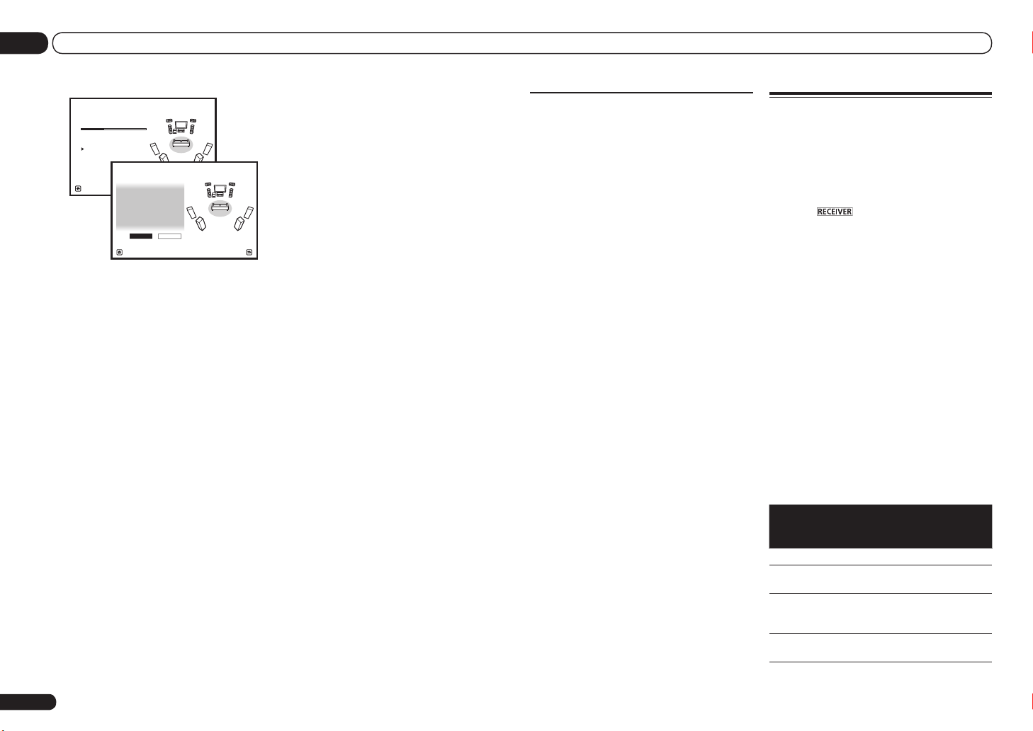
03 Basic Setup
1a.Full Auto MCACC
Now Analyzin g... 2/10
Environmen t Check
Exit Canc el
A/V RECEIVER
Ambient No ise : OK
Microphone :
Speaker YES /NO :
1a.Full Auto MCACC
L : YES
FHL : YES
C : YES
FHR : YES
R : YES
SR : YE S
SBR : Y ES
SBL : YES
SL : YES
SW : YES
10
OK RETRY
Exit Canc el
A/V RECEIVER
The configuration shown on-screen should
reflect the actual speakers you have.
! If you see an ERR message (or the speaker
configuration displayed isn’t correct),
there may be a problem with the speaker
connection. If selecting RETRY doesn’t work,
turn off the power and check the speaker
connections. If there doesn’t seem to be a
problem, you can simply use i/j to select
the speaker and k/l to change the setting
and continue.
! If the speaker is not pointed to the
microphone (listening position) or when
using speakers that affect the phase
(dipole speakers, reflective speakers, etc.),
Reverse Phase may be displayed even if the
speakers are properly connected.
If Reverse Phase is displayed, the speaker’s
wiring (+ and –) may be inverted. Check the
speaker connections.
— If the connections were wrong, turn off
the power, disconnect the power cord,
then reconnect properly. After this,
perform the Full Auto MCACC procedure
again.
— If the connections were right, select
GO NEXT and continue.
7 Make sure ‘OK’ is selected, then press
ENTER.
A progress report is displayed on-screen while
the receiver outputs more test tones to determine the optimum receiver settings.
Again, try to be as quiet as possible while this is
happening. It may take 3 to 10 minutes.
8 The Full Auto MCACC Setup procedure
is completed and the Home Menu menu
reappears automatically.
Be sure to disconnect the microphone from
this receiver upon completion of the Full Auto
MCACC Setup.
! Depending on the characteristics of your
room, sometimes identical speakers with
cone sizes of around 12 cm will end up with
different size settings. You can correct the
setting manually using the Manual speaker
setup on Operating Instructions in CD-ROM.
! The subwoofer distance setting may be
farther than the actual distance from the
listening position. This setting should
be accurate (taking delay and room
characteristics into account) and generally
does not need to be changed.
! If Full Auto MCACC Setup measurement
results are incorrect due to the interaction of
the speakers and viewing environment, we
recommend adjusting the settings manually.
Problems when using the Auto
MCACC Setup
If the room environment is not optimal for the
Auto MCACC Setup (too much background
noise, echo off the walls, obstacles blocking
the speakers from the microphone) the final
settings may be incorrect. Check for household
appliances (air conditioner, fridge, fan, etc.),
that may be affecting the environment and
switch them off if necessary. If there are any
instructions showing in the front panel display,
please follow them.
! Some older TVs may interfere with the
operation of the microphone. If this seems to
be happening, switch off the TV when doing
the Auto MCACC Setup.
Operation Mode Setup
This receiver is equipped with a great number
of functions and settings. The Operation Mode
feature is provided for users who find it difficult
to master all these functions and settings.
One of two settings can be selected for the
Operation Mode: Expert and Basic.
1 Press on the remote control,
then press HOME MENU.
A Graphical User Interface (GUI) screen
appears on your TV. Use i/j/k/l and
ENTER to navigate through the screens and
select menu items. Press RETURN to exit the
current menu.
2 Select ‘Operation Mode Setup’ from
the Home Menu.
3 Select the Operation Mode setting you
want.
! Expert (default) – Users can set all the
functions by themselves.
! Basic – The number of operable functions is
restricted, and functions whose operations
are restricted are automatically set to achieve
the Pioneer-recommended sound and
picture quality. The functions that can be
operated are shown below. They can be set
as necessary by referring to the operating
instructions.
Operable
functions/
items
HOME MENU
Full Auto
MCACC
Input Name
Input Skip
Descriptions Page
Makes high precision
sound field settings easily.
Input names can be
changed as desired for
easier use.
Inputs not being used are
skipped (not displayed).
19
*1
*1
20
En
Page 21
Basic Setup
03
Operable
functions/
items
Software
Update
Network
Information
Pairing
Bluetooth
Setup
Audio Parameters
MCACC
(MCACC
preset)
DELAY
(Sound Delay)
S.RTRV
(Auto Sound
Retriever)
DUAL
(Dual Mono)
V.SB
(Virtual Surround Back)
V.HEIGHT
(Virtual
Height)
V.DEPTH
(Virtual
Depth)
Other functions
INPUT
SELECT
(INPUT
SELECTOR)
MASTER
VOLUME +/–,
MUTE
LISTENING
MODE
PQLS
Descriptions Page
Updates to the latest version of the software.
Checks the receiver’s IP
address.
Pairs with a Bluetooth
device using AS-BT100 or
AS-BT200.
Selects your favorite
MCACC preset memory.
Adjusts the delay time of
the overall sound.
Plays compressed sound
with high sound quality.
Dual monaural audio
setting.
Creates a virtual surround
back channel sound for
playback.
Creates a virtual height
channel sound for playback.
Plays with a sound field
suited for 3D images.
Switches the input. 22
Use to set the listening
volume.
Only Pioneer-recommended
modes can be selected.
Plays using the PQLS
function.
*1
*1
*1
*1
*1
*1
*1
*1
*1
*1
22
22
*1
Operable
functions/
Descriptions Page
items
PHASE CTRL
(Phase Control)
PHASE CTRL
(Full Band
Phase Control)
iPod iPhone
iPad DIRECT
CONTROL
1 See the Operating Instructions in CD-ROM for
detail.
Plays with phase shifting in
the low range corrected.
The Full Band Phase
Control feature calibrates
the frequency-phase characteristics of the speakers
connected.
Switches the input to iPod/
USB and sets the mode
allowing operation from
the iPod.
4 When you’re finished, press RETURN.
You will return to the Home Menu.
*1
*1
*1
En
21
Page 22
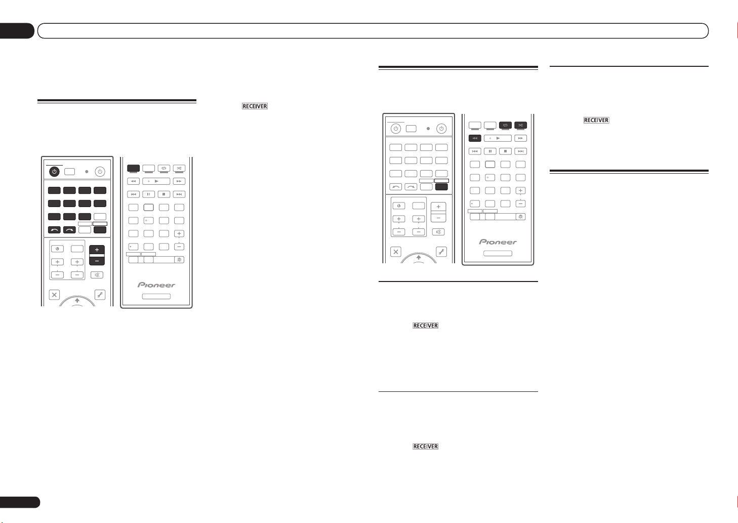
04 Basic playback
Basic playback
Playing a source
Here are the basic instructions for playing a
source (such as a DVD disc) with your home
theater system.
PGM
AUTO / ALC /
STEREO STANDARDADV SURR
MULTI
SOURCERECEIVER
OPERATION
RCU SETUP
BDR
BD DVD DVR HDMI
SAT
USB OPTION
iPod
TUNER
INPUT
SELECT
TV CONTROL
CH
AUDIO
PARAMETER
LIST
TOP MENU
ADPTHMG
CDTV
VIDEO
RECEIVER
TV CTRL
MASTER
VOLUME
INPUT
VOL
MUTE
VIDEO
PARAMETER
TUNE
TOOLS
T.EDIT
1 Switch on your system components
and receiver.
Start by switching on the playback component (for example a DVD player), your TV and
subwoofer (if you have one), then the receiver
(press u RECEIVER).
Make sure that the TV’s video input is set to this
receiver.
2 Select the input function you want to
play.
You can use the input function buttons on the
remote control, INPUT SELECT, or the front
panel INPUT SELECTOR dial.
! If you need to manually switch the input
signal type press SIGNAL SEL.
En
22
DIRECT
HDD DVD
PHASE
CTRL STATUSTHX
/
DTV MPX PQLS
TV
HDMI OUT
1 3
222
SIGNAL SEL
MCACC SLEEP
54 6
CH LEVEL A.ATT DIMMER
807 9
D.ACCESS
/ CLR
ZONE2 ZONE3
RECEIVER
CLASS
ENTER
MENU
AUDIO
INFO
DISP
CH
LIGHT
3 Press to the receiver operation
mode.
4 Press AUTO/ALC/DIRECT
(AUTO SURR/ALC/STREAM DIRECT) to
select ‘AUTO SURROUND’ and start
playback of the source.
If you’re playing a Dolby Digital or DTS surround
sound source, you should hear surround sound.
If you are playing a stereo source, you will only
hear sound from the front left/right speakers in
the default listening mode.
! You may need to check the digital audio
output settings on your DVD player or digital
satellite receiver. It should be set to output
Dolby Digital, DTS and 88.2 kHz / 96 kHz PCM
(2 channel) audio, and if there is an MPEG
audio option, set this to convert the MPEG
audio to PCM.
5 Use the MASTER VOLUME +/– to adjust
the volume level.
Listening in surround sound
Using this receiver, you can listen to any source
in surround sound.
MENU
PGM
AUTO / ALC /
STEREO STANDARDADV SURR
MULTI
SOURCERECEIVER
OPERATION
RCU SETUP
BDR
BD DVD DVR HDMI
SAT
USB OPTION
iPod
TUNER
INPUT
SELECT
TV CONTROL
CH
AUDIO
PARAMETER
LIST
TOP MENU
BAND GUIDE
ADPTHMG
CDTV
VIDEO
RECEIVER
TV CTRL
MASTER
VOLUME
INPUT
VOL
MUTE
VIDEO
PARAMETER
TUNE
TOOLS
T.EDIT
Standard surround sound
This receiver provide basic surround sound for
stereo and multichannel sources.
1 Press to the receiver operation
mode.
2 While listening to a source, press
STANDARD (STANDARD SURROUND).
If necessary, press repeatedly to select a listening mode.
Using the Advanced surround
effects
The Advanced surround effects can be used for
a variety of additional surround sound effects.
1 Press to the receiver operation
mode.
2 Press ADV SURR
(ADVANCED SURROUND) repeatedly to
select a listening mode.
DIRECT
HDD DVD
PHASE
CTRL STATUSTHX
/
DTV MPX PQLS
TV
HDMI OUT
1 3
222
SIGNAL SEL
MCACC SLEEP
54 6
CH LEVEL A.ATT DIMMER
807 9
D.ACCESS
/ CLR
ZONE2 ZONE3
RECEIVER
CLASS
ENTER
AUDIO
INFO
DISP
LIGHT
CH
Using the Home THX modes
THX and Home THX are technical standards
created by THX Ltd. for cinema and home theater sound.
1 Press to the receiver operation
mode.
2 Press THX (HOME THX) to select a
listening mode.
Playing an iPod
This receiver has the iPod iPhone iPad USB
terminal that will allow you to control playback
of audio content from your iPod using the controls of this receiver.
! This receiver is compatible with the audio
and video of the iPod nano (audio only for the
iPod nano 1G/2G), iPod fifth generation (audio
only), iPod classic, iPod touch, iPhone, iPhone
3G, iPhone 3GS, iPhone 4 and iPad. However,
some of the functions may be restricted for
some models. The receiver is not compatible
with the iPod shuffle.
! This receiver has been developed and tested
for the software version of iPod/iPhone/iPad
indicated on the website of Pioneer (http://
pioneer.jp/homeav/support/ios/eu/).
! Installing software versions other than
indicated on the website of Pioneer to your
iPod/iPhone/iPad may result in incompatibility
with this receiver.
! iPod, iPhone and iPad are licensed for
reproduction of non-copyrighted materials
or materials the user is legally permitted to
reproduce.
! Features such as the equalizer cannot
be controlled using this receiver, and we
recommend switching the equalizer off before
connecting.
! Pioneer cannot under any circumstances
accept responsibility for any direct or indirect
loss arising from any inconvenience or loss
Page 23
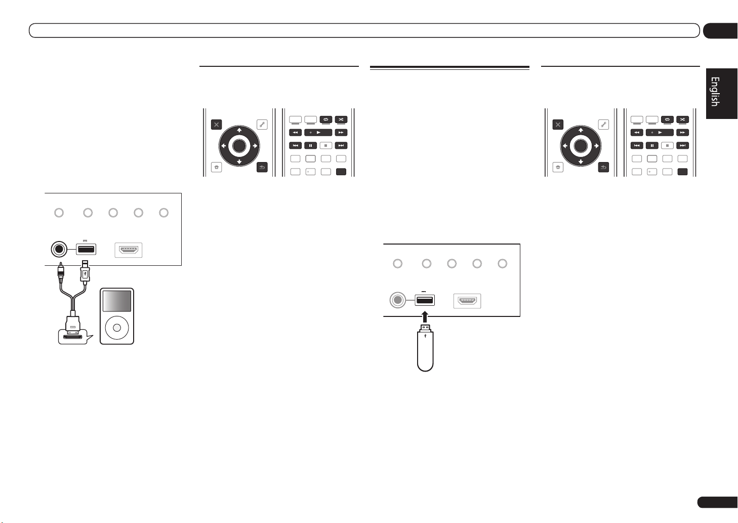
Basic playback
04
of recorded material resulting from the iPod
failure.
! When listening to a track on the iPod in the
main zone, it is possible to control the sub
zone, but not to listen to a different track in
the sub zone from the one playing in the main
zone.
1 Switch the receiver into standby then
use the supplied iPod cable to connect
your iPod to the iPod iPhone iPad USB
terminal on the front panel of this
receiver.
iPod iPhone iPad
DIRECT CONTROL
iPod cable
(supplied)
AUTO SURR/ALC/
STREAM DIRE CT HOME THX
USB
5V 2.1 A
iPod iPhone iPad
ADVANCED
SURROUND
iPod
HDMI 3 INPUT
MENU
STANDARD
SURROUND
2 Press u RECEIVER to switch on the
receiver and your TV.
3 Press iPod USB on the remote control
to switch the receiver to the iPod/USB.
4 Use i/j to select ‘Music’ from the
iPod Top menu.
5 Use i/j and ENTER to select the track
to be played, then press the d button.
Basic playback controls
! Press iPod USB to switch the remote control
to the iPod/USB operation mode.
MENU
PGM
AUTO/ALC
STEREO
AUDIO
PARAMETER
LIST
TOP MENU
BAND GUIDE
PRESET
PTY
SEARCH
HOME
MENU
iPod CTRL
TUNE
ENTER
TUNE
TOOLS
PARAMETER
RETURN
VIDEO
T.EDIT
PRESET
DIRECT STANDARD
HDD DVD
/
DTV MPX PQLS
TV
HDMI OUT
1 3
SIGNAL SEL
MCACC SLEEP
PHASE
22
2
54 6
ADV SURR
CTRL STATUSTHX
AUDIO
INFO
DISP
Playing a USB device
It is possible to play files using the USB interface on the front of this receiver.
! Compatible USB devices include external
magnetic hard drives, portable flash memory
drives (particularly key drives) and digital audio
players (MP3 players) of format FAT16/32.
! Pioneer cannot guarantee compatibility
(operation and/or bus power) with all USB
mass storage devices and assumes no
responsibility for any loss of data that may
occur when connected to this receiver.
1 Switch the receiver into standby
then connect your USB device to the
USB terminal on the front panel of this
receiver.
AUTO SURR/ALC/
iPod iPhone iPad
DIRECT CONTROL
STREAM DIRE CT HOME THX
USB
5V 2.1 A
iPod iPhone iPad
USB mass
storage device
2 Press u RECEIVER to switch on the
receiver and your TV.
! Make sure the receiver is in standby when
disconnecting the USB device.
3 Press iPod USB on the remote control
to switch the receiver to the iPod/USB.
4 Use i/j to select ‘Music’ from the
USB Top menu.
5 Use i/j and ENTER to select the track
to be played, then press the d button.
ADVANCED
SURROUND
HDMI 3 INPUT
STANDARD
SURROUND
Basic playback controls
! Press iPod USB to switch the remote control
to the iPod/USB operation mode.
MENU
PGM
AUTO/ALC
STEREO
TUNE
ENTER
TUNE
TOOLS
VIDEO
PARAMETER
T.EDIT
RETURN
AUDIO
PARAMETER
LIST
TOP MENU
BAND GUIDE
PRESET
PTY
SEARCH
HOME
MENU
iPod CTRL
PRESET
DIRECT STANDARD
HDD DVD
/
DTV MPX PQLS
TV
HDMI OUT
1 3
SIGNAL SEL
MCACC SLEEP
PHASE
22
2
54 6
ADV SURR
CTRL STATUSTHX
AUDIO
INFO
DISP
En
23
Page 24

04 Basic playback
Listening to the radio
1 Press TUNER to select the tuner.
2 Use BAND to change the band (FM or
AM), if necessary.
3 Tune to a station.
There are three ways to do this:
! Automatic tuning – Press and hold TUNE
i/j for about a second. The receiver will
start searching for the next station.
! Manual tuning – To change the frequency
one step at a time, press TUNE i/j.
! High speed tuning – Press and hold TUNE
i/j for high speed tuning. Release the
button at the frequency you want.
Improving FM sound
If the TUNED or STEREO indicator doesn’t
light when tuning to an FM station because the
signal is weak, press MPX to switch the receiver
into mono reception mode.
Using Neural Surround
This feature uses Neural SurroundTM technologies to achieve optimal surround sound from
FM radio.
! While listening to FM radio, press
AUTO/ALC/DIRECT for Neural Surround.
! The Neural Surround mode can be selected
also with STANDARD.
Saving station presets
If you often listen to a particular radio station,
it’s convenient to have the receiver store the
frequency for easy recall whenever you want to
listen to that station.
1 Tune to a station you want to
memorize.
2 Press T.EDIT (TUNER EDIT).
The display shows PRESET MEMORY, then a
blinking memory class.
3 Press CLASS to select one of the seven
classes, then press PRESET k/l to select
the station preset you want.
4 Press ENTER.
After pressing ENTER, the preset class and
number stop blinking and the receiver stores
the station.
Listening to station presets
1 Press TUNER to select the tuner.
2 Press CLASS to select the class in which
the station is stored.
3 Press PRESET k/l to select the
station preset you want.
Playback with HOME MEDIA
GALLERY inputs
This receiver’s Home Media Gallery function
allows you to listen to audio files or listen to
Internet radio stations on a computer or other
component connected to the receiver’s LAN
terminal.
! Photo or video files cannot be played back.
! With Windows Media Player 11 or Windows
Media Player 12, you can even play back
copyrighted audio files on this receiver.
1 Connect the LAN terminal on this
receiver to the LAN terminal on your
router.
See Connecting to the network through LAN
interface on page 17 .
2 Press HMG to select Home Media
Gallery as the input function.
3 Use i/j to select the category you
want to play back, and then press ENTER.
! Internet Radio – Internet radio
! Server Name – Server components on the
network
! Favorites – Favorite songs currently being
registered
! Recently played – Internet Radio listening
history (most recent 20 incidents)
4 Use i/j to select the folder, music
files or Internet radio station to play back,
and then press ENTER.
5 Repeat step 4 to play back the desired
song.
Playing back audio files stored on
components on the network
! Press HMG to switch the remote control to the
HOME MEDIA GALLERY operation mode.
MENU
PGM
AUTO/ALC
STEREO
TUNE
ENTER
TUNE
TOOLS
VIDEO
PARAMETER
RETURN
AUDIO
PARAMETER
LIST
TOP MENU
BAND GUIDE
PRESET
PTY
SEARCH
HOME
MENU
iPod CTRL
T.EDIT
PRESET
DIRECT STANDARD
HDD DVD
/
DTV MPX PQLS
TV
HDMI OUT
1 3
SIGNAL SEL
MCACC SLEEP
PHASE
22
2
54 6
ADV SURR
CTRL STATUSTHX
AUDIO
INFO
DISP
24
En
Page 25

Basic playback
04
Bluetooth ADAPTER for
Wireless Enjoyment of Music
Device not
equipped with
Bluetooth wireless
technology:
Bluetooth
wireless
technology
enabled device:
cell phone
This receiver
INPUT
SELECTOR
STANDBY/ON
Bluetooth wireless
technology
enabled device:
Digital music
player
Music data
ADVANCED
MCACC
FL OFF
Remote control
operation
iPod iPhone iPadHDMI
Digital music
player
+
Bluetooth audio
transmitter
(sold commercially)
Bluetooth
ADAPTER
MASTER
VOLUME
®
Bluetooth® ADAPTER
)
(
VIDEO
FH / FW
(
)
Single
(
L
LAN
(
)
10/100
)
PRE OUT
L
R
)
FRONT HEIGHT / FRONT WIDE /
Single
R L
ADAPTER PORT
(
OUTPUT 5 V
0.1 A MAX
AC IN
)
B
DC OUTPUT
for WIRELESS LAN
(
OUTPUT
5 V
0.6 A MAX
OPTICAL
2
IN1IN2IN3OUT
N
)
(
)
CD
DVR/BDR)(TV/SAT
ER2SURROUND SURR BACK
SURROUND BACK
R
ASSIGNABLE
Important
! Do not move the receiver with the Bluetooth
ADAPTER connected. Doing so could cause
damage or faulty contact.
Refer to the Operating Instructions in CD-ROM
for instructions on how to connect and setup
the Bluetooth ADAPTER and how to play music.
The Bluetooth
®
word mark and logos are registered trademarks owned by Bluetooth SIG,
Inc. and any use of such marks by PIONEER
CORPORATION is under license. Other trademarks and trade names are those of their
respective owners.
© 2011 PIONEER CORPORATION. All rights
reserved.
En
25
Page 26

IMPORTANT
ATTENTION
DANGER D´ELECTROCUTION
NE PAS OUVRIR
Ce symbole de l’éclair, placé dans un
triangle équilatéral, a pour but d’attirer
l’attention de l’utilisateur sur la présence, à
l’intérieur du coffret de l’appareil, de
“tensions dangereuses” non isolées d’une
grandeur suffisante pour représenter un
risque d’électrocution pour les êtres
humains.
AVERTISSEMENT
Cet appareil n’est pas étanche. Pour éviter les risques
d’incendie et de décharge électrique, ne placez près de
lui un récipient rempli d’eau, tel qu’un vase ou un pot
de fleurs, et ne l’exposez pas à des gouttes d’eau, des
éclaboussures, de la pluie ou de l’humidité.
AVERTISSEMENT
Avant de brancher l’appareil pour la première, lisez
attentivement la section suivante.
La tension de l’alimentation électrique disponible
varie selon le pays ou la région. Assurez-vous que
la tension du secteur de la région où l’appareil sera
utilisé correspond à la tension requise (par ex. 230
V ou 120 V), indiquée sur le panneau arrière.
PRÉCAUTION DE VENTILATION
Lors de l’installation de l’appareil, veillez à laisser un
espace suffisant autour de ses parois de manière à
améliorer la dissipation de chaleur (au moins
10 cm à l’arrière et 20 cm de chaque côté).
le dessus,
AVERTISSEMENT
Les fentes et ouvertures du coffret sont prévues pour la
ventilation, pour assurer un fonctionnement stable de
l’appareil et pour éviter sa surchauffe. Pour éviter les
risques d’incendie, ne bouchez jamais les ouvertures et
ne les recouvrez pas d’objets, tels que journaux, nappes
ou rideaux, et n’utilisez pas l’appareil posé sur un tapis
épais ou un lit.
ATTENTION :
POUR ÉVITER TOUT RISQUE
D’ÉLECTROCUTION, NE PAS ENLEVER LE
COUVERCLE (NI LE PANNEAU ARRIÈRE).
AUCUNE PIÈCE RÉPARABLE PAR
L’UTILISATEUR NE SE TROUVE À
L’INTÉRIEUR. CONFIER TOUT ENTRETIEN À
UN PERSONNEL QUALIFIÉ UNIQUEMENT.
D3-4-2-1-3_A1_Fr
D3-4-2-1-4*_A1_Fr
40 cm sur
D3-4-2-1-7b*_A1_Fr
Ce point d’exclamation, placé dans un
triangle équilatéral, a pour but d’attirer
l’attention de l’utilisateur sur la présence,
dans les documents qui accompagnent
l’appareil, d’explications importantes du
point de vue de l’exploitation ou de
l’entretien.
D3-4-2-1-1_A1_Fr
AVERTISSEMENT
Pour éviter les risques d’incendie, ne placez aucune
flamme nue (telle qu’une bougie allumée) sur
l’appareil.
Si la fiche d’alimentation secteur de cet appareil ne
convient pas à la prise secteur à utiliser, la fiche doit
être remplacée par une appropriée. Ce
remplacement et la fixation d’une fiche secteur sur le
cordon d’alimentation de cet appareil doivent être
effectués par un personnel de service qualifié. En cas
de branchement sur une prise secteur, la fiche de
coupure peut provoquer une sérieuse décharge
électrique. Assurez-vous qu’elle est éliminée
correctement après sa dépose.
L’appareil doit être déconnecté en débranchant sa
fiche secteur au niveau de la prise murale si vous
prévoyez une période prolongée de non utilisation
(par exemple avant un départ en vacances).
ATTENTION
L’interrupteur STANDBY/ON de cet appareil ne
coupe pas complètement celui-ci de sa prise secteur.
Comme le cordon d’alimentation fait office de
dispositif de déconnexion du secteur, il devra être
débranché au niveau de la prise secteur pour que
l’appareil soit complètement hors tension. Par
conséquent, veillez à installer l’appareil de telle
manière que son cordon d’alimentation puisse être
facilement débranché de la prise secteur en cas
d’accident. Pour éviter tout risque d’incendie, le
cordon d’alimentation sera débranché au niveau de
la prise secteur si vous prévoyez une période
prolongée de non utilisation (par exemple avant un
départ en vacances).
D3-4-2-1-7a_A1_Fr
D3-4-2-2-1a_A1_Fr
D3-4-2-2-2a*_A1_Fr
Information à destination des utilisateurs sur la collecte et l’élimination des
équipements et batteries usagés
Marquage pour les
équipements
Exemples de marquage
pour les batteries
Ces symboles qui figurent sur les produits, les emballages et/ou les documents
d’accompagnement signifient que les équipements électriques et électroniques et
batteries usagés ne doivent pas être jetés avec les déchets ménagers et font l’objet
d’une collecte sélective.
Pour assurer l’enlèvement et le traitement appropriés des produits et batteries
usagés, merci de les retourner dans les points de collecte sélective habilités
conformément à la législation locale en vigueur.
En respectant les circuits de collecte sélective mis en place pour ces produits, vous
contribuerez à économiser des ressources précieuses et à prévenir les impacts
négatifs éventuels sur la santé humaine et l’environnement qui pourraient résulter
d’une mauvaise gestion des déchets.
Pour plus d’information sur la collecte et le traitement des produits et batteries
usagés, veuillez contacter votre municipalité, votre service de gestion des déchets
ou le point de vente chez qui vous avez acheté ces produits.
Ces symboles ne sont valables que dans les pays de l’Union Européenne.
Pour les pays n’appartenant pas à l’Union Européenne :
Pb
Ce produit est destiné à une utilisation domestique
générale. Toute panne due à une utilisation autre qu'à
des fins privées (comme une utilisation à des fins
commerciales dans un restaurant, dans un autocar
ou sur un bateau) et qui nécessite une réparation
sera aux frais du client, même pendant la période de
garantie.
Si vous souhaitez jeter ces articles, veuillez contacter les autorités ou revendeurs
locaux pour connaître les méthodes d’élimination appropriées.
Milieu de fonctionnement
Température et humidité du milieu de fonctionnement :
De +5 °C à +35 °C (de +41 °F à +95 °F) ; Humidité
relative inférieure à 85 % (orifices de ventilation non
obstrués)
N’installez pas l’appareil dans un endroit mal ventilé ou
un lieu soumis à une forte humidité ou en plein soleil
K041_A1_Fr
(ou à une forte lumière artificielle).
Traduction de l’étiquette collée sur le panneau avant
Mise à l'échelle entrées sorties incluspour
K058a_A1_Fr
D3-4-2-1-7c*_A1_Fr
Fr
2
Page 27

Merci pour l’achat de ce produit
Pioneer. Ce guide rapide contient
les instructions relatives aux raccordements et opérations de base
permettant une utilisation simple de
ce récepteur. Pour des descriptions
plus détaillées du récepteur, référez-vous au “Mode d’emploi” sur le
CD-ROM fourni. Le mode d’emploi
peut aussi être téléchargé du site
Pioneer (http://www.pioneer.eu).
Si vous utilisez Mac OS, posez le
CD-ROM dans un lecteur de CD
et double-cliquez sur l’icône de
CD-ROM pour trouver le fichier PDF
(Mode d’emploi).
Table des
matières
01 Avant de commencer
Vérification du contenu de la boîte ............... 5
Mise en place des piles .................................. 5
À propos de l’AVNavigator
(CD-ROM inclus) ............................................. 5
Télécommande ...............................................6
02 Raccordement de votre
équipement
Raccordement de votre équipement ............ 8
Détermination des enceintes à utiliser ........ 8
Disposition des enceintes .............................. 9
Raccordement des enceintes ....................... 9
Installation de votre système
d’enceintes .................................................... 10
Sélection du système d’enceintes .............. 11
À propos de la liaison audio ........................11
À propos du convertisseur vidéo ................. 11
À propos de l’HDMI ...................................... 12
Raccordement d’un téléviseur ou de
lecteurs .......................................................... 13
Raccordement d’un enregistreur HDD/
DVD, d’un enregistreur BD et d’autres
sources vidéo ................................................14
Connexion d’un récepteur satellite/
câble ou d’un autre type de décodeur ........ 15
Raccordement d’autres composants
audio .............................................................. 15
Raccordement des antennes AM/FM ........16
Configuration MULTI-ZONE ......................... 16
Raccordement au réseau par
l’interface LAN ..............................................17
Raccordement à un réseau LAN sans fil .... 17
Branchement du récepteur .........................18
03 Configuration de base
Obtention automatique d’un réglage
sonore optimal (Full Auto MCACC)............. 19
Configuration du mode de
fonctionnement ............................................ 21
04 Lecture de base
Lecture d’une source ................................... 22
Écoute en surround ...................................... 22
Lecture d’un iPod ......................................... 22
Lecture d’un dispositif USB ......................... 23
Écoute de la radio ......................................... 24
Lecture par les entrées HOME MEDIA
GALLERY ........................................................24
ADAPTATEUR Bluetooth pour l’écoute
de musique sans fil ...................................... 25
Fr
3
Page 28

Organigramme des réglages sur le
récepteur
Organigramme pour les raccordements réglages du récepteur
Cet appareil est un récepteur AV à part entière présentant un grand nombre de fonctions et de
prises. Il peut être utilisé facilement lorsque les raccordements et les réglages mentionnés ci-dessous ont été effectués.
Point de réglage nécessaire: 1, 2, 3, 4, 6, 8, 10
! Ces éléments sont mentionnés dans le Guide rapide.
Réglage à effectuer si nécessaire: 5, 7, 9, 11, 12, 13, 14
! Ces éléments sont expliqués dans le “Mode d’emploi” présent sur le CD-ROM fourni.
Important
Les réglages initiaux du récepteur peuvent être effectués sur l’ordinateur à l’aide de Wiring Navi
sur le CD-ROM AVNavigator livré avec le récepteur. Dans ce cas, pratiquement les mêmes raccordements et réglages que ceux mentionnés aux étapes 2, 3, 4, 6, 7, 8 et 9 peuvent être effectués de
manière interactive. Pour les instructions concernant l’emploi de l’AVNavigator, consultez la section À propos de l’AVNavigator (CD-ROM inclus) à la page 5 .
1 Avant de commencer
! Vérification du contenu de la boîte à la page 5
! Mise en place des piles à la page 5
j
2 Détermination de l’application des enceintes (page 8)
! Système surround 7.2 canaux (Avant Haut)
! Système surround 7.2 canaux (Avant Large)
! Système surround 7.2 canaux et raccordement des enceintes B
! Système surround 5.2 canaux et raccordement avant pour la double amplification
(Surround haute qualité)
! Système surround 5.2 canaux et raccordement de la ZONE 2 (Multizone)
j
3 Raccordement des enceintes
! Disposition des enceintes à la page 9
! Raccordement des enceintes à la page 9
! Installation de votre système d’enceintes à la page 10
! Double amplification des enceintes à la page 10
j
4 Raccordement des composants
! À propos de la liaison audio à la page 11
! À propos du convertisseur vidéo à la page 11
! Raccordement d’un téléviseur ou de lecteurs à la page 13
! Raccordement des antennes AM/FM à la page 16
! Branchement du récepteur à la page 18
j
5 Réglage de l’impédance des enceintes
(Seulement si les enceintes raccordées ont une impédance de 6 W à 8 W)
j
6 Mise sous tension
j
7 Changement de la langue de l’affichage sur écran (OSD Language)
j
8 Réglages des enceintes MCACC
! Obtention automatique d’un réglage sonore optimal (Full Auto MCACC) à la page 19
j
9 Le menu Input Setup
(Si vous voulez effectuer d’autres liaisons que celles recommandées)
j
10 Lecture de base (page 22)
j
11 Commutation de la sortie HDMI
j
12 Réglage de la qualité du son et de l’image selon ses préférences
! Utilisation des divers modes d’écoute
! Contrôle de phase pour un son de meilleure qualité
! Amélioration du son avec le contrôle de phase et le contrôle de phase pleine bande
! Mesure de toutes les courbes d’égalisation (SYMMETRY/ALL CH ADJ/FRONT ALIGN)
! Changement du niveau des canaux pendant l’écoute
! Mise en ou hors service de l’égaliseur du calibrage acoustique, de la correction automatique du
son ou de l’optimisation des dialogues
! Réglage de la fonction PQLS
! Réglage des options audio
! Réglages des options vidéo
j
13 Autres ajustements et réglages facultatifs
! Commande par l’HDMI
! Le menu MCACC avancé
! Menus de configuration du système et d’autres configurations
j
14 Utilisation optimale de la télécommande
! Exploitation de plusieurs récepteurs
! Réglage de la télécommande pour la commande d’autres composants
Fr
4
Page 29

Avant de commencer
01
Avant de commencer
Vérification du contenu de la
boîte
Veuillez vérifier que vous avez reçu tous les
accessoires suivants :
! Microphone de configuration (câble : 5 m)
! Télécommande
! Piles sèches IEC R03 de taille AAA (pour
vérifier si le système fonctionne) x 2
! Antenne cadre AM
! Antenne fil FM
! Câble d’iPod
! Convertisseur LAN sans fil (AS-WL300)
(VSX-LX55 seulement)
— Guide rapide
— CD-ROM (Mode d’emploi)
— Câble de liaison
! Cordon d’alimentation
! CD-ROM (AVNavigator)
! Carte de garantie
! Ce guide rapide
Mise en place des piles
Les piles fournies avec l’appareil sont destinées
à vérifier le bon fonctionnement de l’appareil et
risquent de ne pas durer longtemps. Nous vous
conseillons d’utiliser des piles alcalines dont
l’autonomie est plus longue.
AVERTISSEMENT
! N’utilisez pas ou ne rangez pas les piles
en plein soleil ou à un endroit très chaud,
comme dans une voiture ou près d’un appareil
de chauffage. Les piles pourraient fuir,
surchauffer, exploser ou prendre feu. Cela
peut aussi réduire leur durée de vie et leurs
performances.
ATTENTION
Toute utilisation incorrecte des piles peut
causer des accidents, comme une fuite ou une
explosion. Prenez les précautions suivantes :
! N’utilisez jamais une pile neuve avec une pile
usagée.
! Insérez correctement les pôles positif et
négatif des piles en suivant les marques du
boîtier.
! Des piles de forme identique peuvent avoir des
tensions différentes. Utilisez uniquement des
piles de même type.
! Lorsque vous éliminez des piles / batteries
usées, veuillez vous conformer aux normes
gouvernementales ou aux règles des
institutions publiques environnementales en
vigueur dans votre pays ou région.
À propos de l’AVNavigator
(CD-ROM inclus)
Le CD-ROM AVNavigator inclus contient
Wiring Navi, une application permettant de
faire facilement les liaisons et les réglages
initiaux de manière interactive. Vous obtiendrez
facilement des réglages initiaux très précis simplement en suivant les instructions apparaissant à l’écran pour effectuer les raccordements
et réglages.
Vous trouverez aussi d’autres caractéristiques
facilitant l’emploi de diverses fonctions, par
exemple un Manuel interactif fonctionnant avec
le récepteur, la possibilité de mettre à jour les
divers logiciels et une application MCACC qui
permet de vérifier les mesures obtenues sur des
graphiques en 3 dimensions.
Installation de l’AVNavigator
1 Posez le CD-ROM AVNavigator inclus
dans le lecteur CD de votre ordinateur.
! L’écran d’installation s’affiche. Passez à
l’étape 2.
! Si l’écran d’installation n’apparaît pas,
double-cliquez sur l’icône de CD-ROM puis
démarrez l’installateur (AVNV_XXX_xxx.exe).
2 Suivez les instructions apparaissant à
l’écran pour installer l’application.
Lorsque “Finish” est sélectionné, l’installation
est terminée.
3 Retirez le CD-ROM AVNavigator inclus
du lecteur CD de votre ordinateur.
Traitement du CD-ROM
Environnement d’exploitation
! Ce CD-ROM peut être utilisé avec Microsoft®
Windows® XP/Vista/7.
! Un navigateur est parfois utilisé pour les
fonctions de l’AVNavigator. Le navigateur pris
en charge est Microsoft Internet Explorer 6,
7 et 8. Avec d’autres navigateurs, certaines
fonctions peuvent être limitées ou ne pas
s’afficher correctement.
De plus, même si le navigateur est pris
en charge, selon ses réglages, certaines
fonctions peuvent être restreintes et les
informations peuvent ne pas s’afficher
correctement.
Précautions d’utilisation
! Ce CD-ROM est conçu pour être utilisé avec
un ordinateur personnel. Il ne peut pas être
utilisé avec un lecteur de DVD ni un lecteur
de CD audio. Essayer de lire ce CD-ROM avec
un lecteur de DVD ou un lecteur de CD audio
peut endommager les enceintes ou causer
une altération auditive à cause du volume
sonore élevé qui pourrait être produit.
Licence
! Veuillez accepter les “Conditions d’utilisation”
indiquées ci-dessous avant d’utiliser ce
CD-ROM. Ne l’utilisez pas si vous ne souhaitez
pas accepter les conditions d’utilisation.
Vous devez aussi accepter le “Contrat de
licence” qui s’affiche lors de l’installation de
l’AVNavigator.
Conditions d’utilisation
! Les droits d’auteur des données de ce
CD-ROM appartiennent à PIONEER
CORPORATION. Un transfert, une copie, une
diffusion, une transmission publique, une
traduction, une vente, un prêt ou toute autre
action non autorisée qui sort des limites de
“l’utilisation personnelle” ou d’une “citation”,
comme défini par les lois sur les droits
d’auteur, peut être soumise à des actions
pénales. L’autorisation d’utiliser ce CD-ROM
est donnée sous licence de PIONEER
CORPORATION.
Avis de non-responsabilité
! PIONEER CORPORATION ne garantit pas
le fonctionnement de ce CD-ROM pour les
ordinateurs personnels utilisant n’importe
lequel des systèmes d’exploitation applicables.
De plus, PIONEER CORPORATION ne peut
être tenu responsable des dommages subis à
la suite de l’utilisation de ce CD-ROM et n’est
tenu à aucune compensation. Les noms des
sociétés privées, des produits ou d’autres
entités citées ici sont des marques déposées
ou des marques de commerce de leur
entreprise respective.
Fr
5
Page 30

01 Avant de commencer
Utilisation de l’AVNavigator
1 Cliquez sur [AVNavigator] sur le
bureau pour lancer l’AVNavigator.
L’AVNavigator s’ouvre et Wiring Navi démarre.
L’écran de sélection de langue apparaît. Suivez
les instructions apparaissant à l’écran pour
effectuer les raccordements et les réglages
automatiques.
Wiring Navi démarre automatiquement seulement la première fois que l’AVNavigator est
ouvert.
2 Sélectionnez et utilisez la fonction
souhaitée.
L’AVNavigator comprend les fonctions suivantes :
! Wiring Navi – Vous indique de manière
interactive comment effectuer les
raccordements et les réglages initiaux.
Des réglages initiaux extrêmement précis
peuvent facilement être effectués.
! Interactive Manual – Affiche
automatiquement les pages décrivant les
fonctions mises en service sur le récepteur.
Le récepteur peut aussi être actionné depuis
le Manuel interactif.
! Glossary – Affiche des pages du glossaire.
! MCACC Appli – Affiche les mesures
obtenues à la suite de la configuration
MCACC avancée de manière vivante sur
l’ordinateur.
Des instructions spéciales sont présentes
pour l’application MCACC. Ces instructions
se trouvent dans les menus de l’AVNavigator
Interactive Manual. Consultez-les lorsque
vous utilisez l’application MCACC.
! Software Update – Permet la mise à jour de
divers types de logiciels.
! Settings – Sert à effectuer divers réglages de
l’AVNavigator.
! Detection – Sert à détecter le récepteur.
Remarque
Pour utiliser l’AVNavigator d’un autre modèle,
désinstallez d’abord (supprimez) l’AVNavigator
de ce récepteur, puis installez l’AVNavigator de
l’autre modèle.
Suppression de l’AVNavigator
Vous pouvez procéder de la façon suivante
pour désinstaller (supprimer) l’AVNavigator de
l’ordinateur.
% Supprimez-le du panneau de
commande de l’ordinateur.
Depuis le menu Démarrer, cliquez sur
“Program” d “PIONEER CORPORATION”
d “AVNavigator(VSX-LX55 ou VSX-2021)” d
“Uninstall”.
Télécommande
Cette section explique comment utiliser la
télécommande du récepteur.
MULTI
SOURCERECEIVER
1
2,3
4
5
6
7
8
9
10
OPERATION
RCU SETUP
BDR
BD DVD DVR
SAT
HMG
CDTV
USB OPTION
iPod
TUNER
VIDEO
TV CTRL
SELECT
INPUT
MASTER
VOLUME
INPUT
TV CONTROL
VOL
CH
AUDIO
PARAMETER
TOP MENU
BAND GUIDE
PRESET
PTY
SEARCH
iPod CTRL
AUTO / ALC /
DIRECT
HDD DVD
TV
/
DTV MPX PQLS
1 32
SIGNAL SEL
CH LEVEL A.ATT DIMMER
D.ACCESS
/ CLR
ZONE 2 ZONE 3
LIST
TUNE
ENTER
HOME
TUNE
MENU
PGM
STEREO STANDARD
PHASE
HDMI OUT
MCACC SLEEP
54 6
807 9
RECEIVER
CTRL STATUSTHX
CLASS
ENTER
TOOLS
3
MUTE
PARAMETER
HDMI
ADPT
RECEIVER
VIDEO
T.EDIT
PRESET
RETURN
MENU
ADV SURR
AUDIO
INFO
DISP
CH
LIGHT
11
12
13
14
15
16
La télécommande présente les deux codes couleurs suivants, selon le composant utilisé :
! Blanc – Commande du récepteur, Commande
du téléviseur
! Bleu – Autres commandes (Consultez le
mode d’emploi sur le CD-ROM pour plus
d’informations.)
1 u RECEIVER
Permet de commuter le récepteur entre veille et
mise sous tension.
2 MULTI OPERATION
Permet d’effectuer une série d’opérations.
3 RCU SETUP
Sert à saisir le code de préréglage lors des
réglages de la télécommande et à spécifier le
mode de commande à distance.
4 Touches de fonction d’entrée
Servent à sélectionner la commande d’autres
composants.
Utilisez INPUT SELECT c/ d pour sélectionner
la fonction d’entrée (page 22).
5 TV CTRL
Sert à spécifier le code de fabrication du téléviseur pour la commande du téléviseur.
6 Touches TV CONTROL
Ces touches sont réservées à la commande du
téléviseur affecté à la touche TV CTRL.
7 Touches de réglage du récepteur
Appuyez d’abord sur pour accéder à :
! AUDIO PARAMETER – Pour accéder aux
options Audio.
! VIDEO PARAMETER – Pour accéder aux
options Vidéo.
! HOME MENU – Pour accéder au menu
principal.
! RETURN – Pour valider le réglage et quitter la
page actuelle du menu.
8 i/j/k/l/ENTER
Utilisez les flèches lors de la configuration de
votre système surround et des options Audio
ou Vidéo.
Fr
6
Page 31

Avant de commencer
01
9 Touches de commande du récepteur
Appuyez d’abord sur pour accéder à :
! AUTO/ALC/DIRECT – Pour commuter
entre les modes de Surround automatique,
Contrôle automatique des niveaux, Surround
optimal et Flux direct.
! STEREO – Pour sélectionner le mode de
lecture stéréo.
! STANDARD – Pour accéder au décodage
standard et basculer sur les différents modes
(2 Pro Logic, Neo:6, etc.) (page 22).
! ADV SURR – Pour basculer entre les
différents modes surround (page 22).
! THX – Pour sélectionner un mode d’écoute
Home THX (page 22).
! PHASE CTRL – Pour activer/désactiver la
correction de phase.
Le contrôle de phase pleine bande peut aussi
est commuté.
! STATUS – Pour vérifier les réglages du
récepteur sélectionné.
! PQLS – Pour sélectionner le réglage PQLS.
! HDMI OUT – Pour commuter la prise de
sortie HDMI.
! SIGNAL SEL – Sert à sélectionner un signal
d’entrée.
! MCACC – Pour commuter entre les
préréglages MCACC.
! SLEEP – Pour mettre le récepteur en mode
sommeil et sélectionner le temps devant
s’écouler avant le sommeil.
! CH LEVEL – Appuyez plusieurs fois sur cette
touche pour sélectionner un canal, puis
utilisez k/l pour régler le niveau.
! A.ATT – Pour atténuer (diminuer) le niveau
d’un signal d’entrée analogique et éliminer la
distorsion.
! DIMMER – Pour obscurcir ou éclaircir
l’affichage.
10 Sélecteurs MULTI-ZONE
Permet d’agir sur les appareils de la zone principale, de la ZONE 2 et de la ZONE 3.
11 Témoin de télécommande
S’allume lorsqu’un signal de commande est
envoyé par la télécommande.
12 OPTION
Les codes préréglés des dispositifs qui seront
utilisés peuvent être enregistrés sur la télécommande et les commandes peuvent être enregistrées par le mode d’apprentissage.
13
Sert à basculer la télécommande sur la commande du récepteur (permet de sélectionner
les commandes blanches).
Cette touche est utilisée pour effectuer des
opérations dans la zone principale.
Elle sert également à configurer le son
surround.
14 MASTER VOLUME +/–
Sert à régler le volume d’écoute.
15 MUTE
Sert à couper le son ou à le rétablir s’il a été
coupé (le réglage du volume rétablit également
le son).
16 LIGHT
Sert à allumer ou éteindre l’éclairage des
touches.
Il y a quatre modes d’éclairage des touches.
Fr
7
Page 32

02 Raccordement de votre équipement
Raccordement de votre
équipement
Raccordement de votre
équipement
Ce récepteur vous offre de nombreuses possibilités de liaisons, ce qui ne signifie pas nécessairement que cela soit compliqué. Ce chapitre
explique les différents types de composants
que vous pouvez raccorder pour réaliser votre
système de home cinéma.
ATTENTION
! Avant de réaliser ou de modifier des liaisons,
éteignez les appareils et débranchez le
cordon d’alimentation de la prise électrique.
Le cordon d’alimentation se branche en tout
dernier lieu.
! Lorsque vous raccordez des appareils, laissez
les cordons d’alimentation des appareils à
raccorder débranchés des prises murales.
! Selon l’appareil à raccorder (amplificateur,
récepteur, etc.), les méthodes de
raccordement et les noms des prises peuvent
être différents de ce qui est indiqué dans
ce manuel. Reportez-vous aussi au mode
d’emploi des appareils respectifs.
Détermination des enceintes à
utiliser
Cet appareil permet de réaliser différents systèmes surround selon le nombre d’enceintes
que vous possédez.
! Des enceintes doivent être raccordées aux
canaux avant gauche et droit (L et R).
! Il est également possible de ne raccorder
qu’une seule des enceintes surround arrière
(SB), voire aucune.
Fr
8
! Si vous possédez deux caissons de grave, le
second caisson de grave peut être raccordé à
la prise SUBWOOFER 2. Avec deux caissons
de grave vous augmenterez les sons graves
et obtiendrez un son plus puissant. Dans ce
cas, les deux caissons de grave produiront le
même son.
Choisissez votre configuration parmi les Plans
[A] à [E] ci-dessous.
Important
! Speaker System doit être réglé si vous
utilisez une des liaisons figurant ci-dessous
à l’exception de [A] (consultez Réglage du
système d’enceintes dans le mode d’emploi
sur le CD-ROM).
! Le son n’est pas restitué simultanément par
les enceintes avant en position haute, avant
en position large, de la paire d’enceintes B et
surround arrière. Les enceintes sollicitées sont
différentes selon le signal d’entrée ou le mode
d’écoute.
[A] Système surround 7.2 canaux (Avant
Haut)
*Réglage par défaut
! Réglage du Speaker System : Normal(SB/FH)
FHR
FHL
L
SW 2
SL
R
SW
1
C
SBL
SR
SBR
Dans un système surround impliquant 7,2
canaux, les enceintes avant gauche et droite
(L/R), l’enceinte centrale (C), les enceintes
avant gauche et droite en position haute (FHL/
FHR), les enceintes surround gauche et droite
(SL/SR), les enceintes surround arrière gauche
et droite (SBL/SBR) et les caissons de grave
(SW 1/SW 2) doivent être raccordés.
Il n’est pas possible de restituer simultanément
le son des enceintes avant en position haute ou
large et des enceintes arrière surround.
Ce système surround produit un son plus fidèle
à la réalité, du haut.
[B] Système surround 7.2 canaux (Avant
Large)
! Réglage du Speaker System :
Normal(SB/FW)
R
SW
1
SBL
FWR
SR
SBR
FWL
L
C
SW 2
SL
Selon ce plan, les enceintes avant gauche et
droite en position haute, comme indiqué en
[A], sont remplacées par des enceintes avant
gauche et droite en position large (FWL/FWR).
Il n’est pas possible de restituer simultanément
le son des enceintes avant en position haute ou
large et des enceintes arrière surround.
Ce système surround produit un son fidèle à la
réalité sur une surface plus large.
[C] Système surround 7.2 canaux et
raccordement des enceintes B
! Réglage du Speaker System : Speaker B
R
L
SW
SW 1
C
2
SL
SBL
SR
SBR
R
L
Speaker B
Ces liaisons permettent de bénéficier d’un son
surround 5.2 canaux dans la zone principale
et du même son en stéréo restitué par les
enceintes B. Si les enceintes B ne sont pas
utilisées, les mêmes liaisons permettent de
bénéficier d’un son surround 7.2 canaux dans
la zone principale.
[D] Système surround 5.2 canaux et
raccordement avant pour la double
amplification (Surround haute qualité)
! Réglage du Speaker System : Front Bi-Amp
Liaison à double amplification des enceintes
avant pour un son surround 5.2 canaux de
grande qualité.
Page 33

Raccordement de votre équipement
02
Front Bi-Amp
R
L
SW
SW 1
C
2
SR
SL
[E] Système surround 5.2 canaux et
raccordement de la ZONE 2 (Multizone)
! Réglage du Speaker System : ZONE 2
Ces liaisons permettent de bénéficier du son
surround 5.2 canaux simultanément dans la
zone principale et d’un son en stéréo sur l’appareil de la ZONE 2. (Les dispositifs pouvant être
sélectionnés sont limités.)
L
Zone principale
SR
Zone
secondaire
R
R
L
SW 1
C
2
SW
SL
ZONE 2
Autres liaisons d’enceintes
! Vous pouvez sélectionner vos liaisons
préférées même si vous disposez de moins
de 5.2 enceintes (à l’exception des enceintes
avant gauche/droite).
! Si vous ne raccordez pas de caisson de
grave, raccordez des enceintes capables de
reproduire les basses fréquences sur le canal
avant. (Sinon, les basses fréquences des
graves étant restituées par les enceintes avant,
celles-ci pourraient être endommagées.)
! Après avoir raccordé les enceintes, effectuez
la configuration Full Auto MCACC (réglage
de l’environnement des enceintes). Consultez
la section Obtention automatique d’un réglage
sonore optimal (Full Auto MCACC) à la page 19.
Disposition des enceintes
Référez-vous au schéma ci-dessous pour la
disposition des enceintes que vous voulez
raccorder.
SW
FHL
L
FWL
2 SW 1
C
30 30
60
SL
120 120
60
SBL
SB
! Positionnez les enceintes surround à 120° du
centre. Si vous (1) utilisez l’enceinte surround
arrière et (2) n’utilisez pas les enceintes
avant en position haute / les enceintes avant
en position large, il est conseillé de placer
l’enceinte surround juste à côté de vous.
FHR
R
FWR
60
SR
SBR
! Si vous voulez raccorder seulement une
enceinte arrière surround, placez-la
directement derrière vous.
! Placez les enceintes avant gauche et droite
en position haute à au moins un mètre
des enceintes avant gauche et droite, et
directement au-dessus.
Raccordement des enceintes
Pour chaque enceinte le récepteur comporte
une borne positive (+) et une borne négative
(–). Prenez soin de les faire correspondre aux
bornes situées sur les enceintes.
ATTENTION
! Ces bornes d’enceintes sont soumises à
une tension DANGEREUSE. Pour éviter
tout risque de décharge électrique lors
du branchement ou débranchement des
câbles d’enceintes, débranchez le cordon
d’alimentation avant de toucher les parties
non isolées.
! Assurez-vous que toute la partie dénudée du
fil d’enceinte est torsadé et inséré entièrement
dans la borne d’enceinte. Si l’un des fils
d’enceinte dénudés devait toucher le panneau
arrière, l’alimentation pourrait être coupée par
mesure de sécurité.
Raccordement des fils dénudés
ATTENTION
Assurez-vous que toutes les enceintes sont
installées de manière stable. Cela permet non
seulement d’améliorer la qualité sonore, mais
aussi de réduire les risques de dommage ou de
blessure si l’enceinte venait à tomber en raison
de chocs extérieurs, tels qu’un tremblement
de terre.
1 Torsadez les fils ensemble.
2 Dévissez la borne et insérez la partie
dénudée des fils.
3 Serrez la borne.
1 2 3
10 mm
Remarque
! Pour plus d’informations sur le branchement
de l’autre extrémité des câbles d’enceinte à
vos enceintes, consultez le mode d’emploi
fourni avec vos enceintes.
! Utilisez un câble à fiche RCA pour raccorder
le caisson de grave. Il n’est pas possible
d’utiliser des câbles d’enceintes.
! Si vous possédez deux caissons de grave, le
second caisson de grave peut être raccordé à
la prise SUBWOOFER 2. Avec deux caissons
de grave vous augmenterez les sons graves
et obtiendrez un son plus puissant. Dans ce
cas, les deux caissons de grave produiront le
même son.
Fr
9
Page 34

02 Raccordement de votre équipement
Installation de votre système d’enceintes
Les enceintes avant gauche et droite sont les seules obligatoires. Notez que vos enceintes surround
principales doivent toujours être raccordées par paire. Cependant, si vous le souhaitez, vous pouvez
ne raccorder qu’une seule enceinte surround arrière (elle doit être raccordée à la borne surround
arrière gauche).
Raccordement surround standard
Les bornes avant hautes peuvent aussi être utilisées
pour les enceintes avant larges et la paire d’enceintes B.
10
Avant Haut droite
Réglage Avant Haut
Réglage Avant Large
Avant Large droite
Réglage Enceintes B
Centrale Caisson de grave 2Caisson de grave 1
6
IN5IN
(DVD)
R L R L
A
1
2
OUT 1
(DVR/BDR)
(CONTROL)
COAXIAL
MONITOR
OUT
VIDEO
CD
DVR/BDR
IN
OUTOUT
FRONT CENTER
FRONT
AUDIO
Les bornes de surround arrière peuvent
aussi être utilisées pour la ZONE 2.
Réglage Surround 5.2 canaux
Réglage Surround 6.2 canaux
Réglage Surround 7.2 canaux
Réglage ZONE 2
ASSIGNABLE
IN
(
DVD
IN
(
DVR/
BDR
MONITOR
OUT
Surround
droite
Avant droite
IN1IN
HDMI
ASSIGNABLE
1 6
COMPONENT VIDEO
Y PBP
1
)
2
)
ANTENNA
RS-232C
AM LOOP
(
OUTPUT 5 V
)
150 mA MAX
EXTENSION
Enceinte B - droite Enceinte B - gauche
LINE LEVEL
INPUT
4
IN
2
(VIDEO)
BD IN
R
TV/SAT VIDEO
DVD
ZONE 2
ZONE 3
OUT
IN IN IN IN
FM UNBAL 75
SPEAKERS
IR
IN
OUT
1IN2
IN
OUT
(OUTPUT 12 V
CONTROL
TOTAL 150 mA MAX)
12 V TRIGGER
Non raccordé Non raccordé
Non raccordé Surround arrière
Surround arrière droite Surround arrière gauche
ZONE 2 - droite ZONE 2 - gauche
Fr
DC OUTPUT
for WIRELESS LAN
OUT 2
ASSIGNABLE ASSIGNABLE
OPTICAL
2
IN1IN2IN3OUT
IN1IN
(CD)(
)
DVD
SUBWOOFER
SURROUND SURR BACK
1 2
CENTER
SURROUND
R L
Avant Haut gauche
Avant Large gauche
LINE LEVEL
INPUT
ADAPTER PORT
LAN
(
OUTPUT
(
)
10/100
5 V
)
0.6 A MAX
(
)
(
)
DVR/BDR)(TV/SAT
VIDEO
FH / FW
PRE OUT
(
)
Single
L
R
(
)
SURROUND BACK
FRONT HEIGHT / FRONT WIDE /
Single
R L
(
OUTPUT 5 V
0.1 A MAX
B
)
Avant gauche
AC IN
Surround
gauche
Double amplification des enceintes
Il y a double amplification lorsque vous reliez les amplificateurs internes hautes et basses fréquences des enceintes à différents amplificateurs externes pour obtenir une meilleure répartition
des fréquences. Pour cela, vos enceintes doivent supporter la double amplification (en disposant
de bornes distinctes pour les hautes et les basses fréquences) et l’amélioration de la qualité du son
dépendra du type d’enceintes utilisé.
LAN
(
10/100
)
PRE OUT
L
R
(
)
FRONT HEIGHT / FRONT WIDE /
Single
R L
ADAPTER PORT
)
(
OUTPUT 5 V
0.1 A MAX
Avant gauche
High
Low
AC IN
)
B
Enceinte pour double
amplification
Avant droite
Enceinte pour double
amplification
IN1IN
HDMI
ASSIGNABLE
1 6
ASSIGNABLE
COMPONENT VIDEO
Y PBP
R
1
IN
(
)
DVD
2
IN
(
DVR/
)
BDR
MONITOR
OUT
ANTENNA
RS-232C
FM UNBAL 75
AM LOOP
IN
OUT
(
OUTPUT 5 V
CONTROL
)
150 mA MAX
EXTENSION
Caisson de grave 1 Caisson de grave 2
2
ZONE 2
ZONE 3
OUT
1IN2
IN
High
Low
4
IN
(VIDEO)
BD IN
TV/SAT VIDEO
DVD
IN IN IN IN
SPEAKERS
IR
OUT
(OUTPUT 12 V
TOTAL 150 mA MAX)
12 V TRIGGER
6
IN5IN
(DVD)
(DVR/BDR)
MONITOR
DVR/BDR
OUTOUT
AUDIO
FRONT CENTER
R L R L
A
1
2
Surround droite Surround gauche
OUT
VIDEO
CD
IN
Centrale
OUT 1
(CONTROL)
COAXIAL
FRONT
DC OUTPUT
for WIRELESS LAN
OUT 2
ASSIGNABLE ASSIGNABLE
OPTICAL
2
IN1IN2IN3OUT
IN1IN
(CD)(
)
DVD
SUBWOOFER
SURROUND SURR BACK
1 2
CENTER
SURROUND
R L
(
OUTPUT
5 V
0.6 A MAX
(
)
DVR/BDR)(TV/SAT
SURROUND BACK
)
(
VIDEO
FH / FW
(
)
Single
ATTENTION
! La plupart des enceintes dotées de bornes High et Low arborent deux plaques métalliques reliant
les bornes High et les bornes Low. Il faut retirer ces plaques lors de la double amplification des
enceintes, sans quoi vous pourriez sérieusement endommager l’amplificateur. Consultez le mode
d’emploi des enceintes pour de plus amples informations.
! Si vos enceintes disposent d’un circuit d’aiguillage amovible, assurez-vous qu’il n’a pas été retiré si
vous utilisez la double amplification. Sans quoi vos enceintes pourraient être endommagées.
Page 35

Raccordement de votre équipement
02
Double câblage de vos enceintes
Vos enceintes peuvent aussi recevoir un
double câblage si elles acceptent la double
amplification.
! Avec ces liaisons, le réglage Speaker System
n’a pas d’importance.
ATTENTION
! Ne raccordez pas de cette façon différentes
enceintes à la même borne.
! Lors du double câblage, prenez les mêmes
précautions que pour la double amplification,
comme indiqué ci-dessus.
% Pour le double câblage d’une enceinte,
raccordez deux cordons d’enceinte à la
borne d’enceinte sur le récepteur.
Sélection du système
d’enceintes
Les bornes avant haut peuvent être utilisées
pour raccorder des enceintes avant en position
large et la paire d’enceintes B, en plus des
enceintes avant en position haute. De même,
les bornes surround arrière peuvent être utilisées pour les liaisons à double amplification et
de la ZONE 2, en plus des enceintes surround
arrière. Effectuez ce réglage selon la situation.
Réglage pour les enceintes avant
en position haute
*Réglage par défaut
1 Raccordez une paire d’enceintes aux
bornes d’enceintes avant en position
haute.
Consultez la section Raccordement surround
standard à la page 10 .
2 Si nécessaire, sélectionnez
‘Normal(SB/FH)’ dans le menu
Speaker System.
Pour ce faire, consultez la section Réglage du
système d’enceintes dans le mode d’emploi sur
le CD-ROM.
Réglage pour les enceintes avant
en position large
1 Raccordez une paire d’enceintes aux
bornes d’enceintes avant en position
haute.
Consultez la section Raccordement surround
standard à la page 10 .
2 Sélectionnez ‘Normal(SB/FW)’ sur le
menu Speaker System.
Pour ce faire, consultez la section Réglage du
système d’enceintes dans le mode d’emploi sur
le CD-ROM.
Réglage pour les enceintes B
Vous pouvez écouter le son en stéréo dans une
autre pièce.
1 Raccordez une paire d’enceintes aux
bornes d’enceintes avant en position
haute.
Consultez la section Raccordement surround
standard à la page 10 .
2 Sélectionnez ‘Speaker B’ sur le menu
Speaker System.
Pour ce faire, consultez la section Réglage du
système d’enceintes dans le mode d’emploi sur
le CD-ROM.
Réglage pour la double
amplification
Liaison à double amplification des enceintes
avant pour un son surround 5.2 canaux de
grande qualité.
1 Raccordez des enceintes compatibles
avec la double amplification aux bornes
d’enceintes avant et surround arrière.
Consultez la section Double amplification des
enceintes à la page 10 .
2 Sélectionnez ‘Front Bi-Amp’ sur le
menu Speaker System.
Pour ce faire, consultez la section Réglage du
système d’enceintes dans le mode d’emploi sur
le CD-ROM.
Réglage pour la ZONE 2
Ces liaisons permettent à l’appareil de la zone
principale de restituer un son surround à 5.2
canaux et à l’appareil de la ZONE 2 de restituer
un son en stéréo.
1 Raccordez une paire d’enceintes aux
bornes d’enceintes surround arrière.
Consultez la section Raccordement surround
standard à la page 10 .
2 Sélectionnez ‘ZONE 2’ sur le menu
Speaker System.
Pour ce faire, consultez la section Réglage du
système d’enceintes dans le mode d’emploi sur
le CD-ROM.
À propos de la liaison audio
Types de câbles et de
bornes
HDMI Audio HD
Numérique (Coaxial) Audio numérique
Numérique (Optique)
Priorité des signaux audio
RCA (Analogique)
(Blanc/Rouge)
! Avec un câble HDMI les signaux vidéo et audio
peuvent être transférés par un seul câble tout
en conservant leur grande qualité.
Signaux audio
transférables
conventionnel
Audio analogique
conventionnel
À propos du convertisseur
vidéo
Avec le convertisseur vidéo, vous avez la garantie que toutes les sources vidéo seront restituées par toutes les prises MONITOR VIDEO
OUT. À l’exception toutefois des sources HDMI,
vu l’impossibilité de sous-échantillonner cette
résolution, vous devrez raccorder votre moniteur/téléviseur à la sortie HDMI du récepteur
pour relier cette source vidéo.
Si plusieurs composants vidéo sont affectés à
la même fonction d’entrée (consultez la section
Le menu Input Setup dans le mode d’emploi sur
Fr
11
Page 36

02 Raccordement de votre équipement
le CD-ROM), le convertisseur donne la priorité
aux sources HDMI, composantes, puis composites (dans cet ordre).
Borne pour le
raccordement d’une
source
HDMI IN HDMI OUT
Y PBP
R
COMPONENT
VIDEO IN
Haute qualité de l’image
VIDEO IN
Signaux vidéo pouvant être restitués
Borne pour le
raccordement d’un
téléviseur
Y
COMPONENT VIDEO
MONITOR OUT
VIDEO
MONITOR OUT
Remarque
! Si le signal vidéo n’apparaît sur votre
téléviseur, essayez d’ajuster les réglages de
la résolution de votre composant ou écran.
Notez que pour certains composants (comme
les consoles de jeux vidéo), la conversion
des résolutions est impossible. Dans ce
cas, essayez de changer la conversion vidéo
numérique (dans Réglage des options vidéo
dans le mode d’emploi sur le CD-ROM) OFF.
! Les signaux de l’entrée vidéo à composantes
ayant une résolution de 480i/576i, 480p/576p,
720p et 1080i peuvent être convertis pour
être restitués par la sortie HDMI. Les signaux
1080p ne peuvent pas être convertis.
! Seuls les signaux de l’entrée vidéo à
composantes ayant en entrée une résolution
de 480i/576i peuvent être convertis pour
être restitués par les prises MONITOR OUT
composites.
! Pour une image optimale, THX conseille
de changer la conversion vidéo numérique
(dans Réglage des options vidéo dans le mode
d’emploi sur le CD-ROM) OFF.
Fr
12
Ce produit fait appel à des principes technologiques destinés à interdire la piraterie des
œuvres protégées par des droits d’auteur,
principes qui sont eux-mêmes couverts aux
États-Unis par des brevets et d’autres formes
de propriété intellectuelle appartenant à Rovi
Corporation. La rétro-technique et le désassemblage sont proscrits.
B
P
P
R
À propos de l’HDMI
La liaison HDMI permet de transmettre des
signaux vidéo numériques non compressés
de même que la plupart des signaux audio
numériques.
Ce récepteur intègre l’Interface Multimédia
Haute Définition (HDMI®).
Il prend en charge les fonctions suivantes
lorsque les liaisons HDMI sont utilisées.
! Transfert numérique de vidéo non compressée
(contenu protégé par l’HDCP (1080p/24,
1080p/60, etc.))
! Transfert de signaux 3D
! Transfert de signaux Deep Color
! Transfert de signaux x.v.Color
! ARC (Canal de retour audio)
! Entrée de signaux audio numériques PCM
linéaires multicanaux (192 kHz ou inférieur)
jusqu’à 8 canaux
! Entrée des signaux audio numériques aux
formats suivants :
— Dolby Digital, Dolby Digital Plus, DTS, Son à
débit élevé (Dolby TrueHD, DTS-HD Master
Audio, DTS-HD High Resolution Audio),
DVD-Audio, CD, SACD (signal DSD), Video
CD, Super VCD
! Commande synchronisée d’autres
composants avec la fonction Control par
l’HDMI (consultez la section Commande par
l’HDMI dans le mode d’emploi sur le CD-ROM)
Remarque
! Une connexion HDMI ne peut être réalisée
qu’avec les composants équipés de prises
DVI compatibles avec le DVI et HDCP (High
Bandwidth Digital Content Protection). Si vous
choisissez un prise DVI, vous devez disposer
d’un adaptateur séparé (DVIdHDMI).
apparaît sur l’afficheur du panneau avant.
Avec certains composants compatibles avec
le HDCP, ce message s’affiche aussi, mais
dans la mesure où l’image est normale, il n’y a
pas lieu de s’inquiéter.
! Selon le composant raccordé, l’utilisation
d’une liaison DVI peut entraîner des transferts
de signaux peu fiables.
! Ce récepteur prend en charge les SACD,
Dolby Digital Plus, Dolby TrueHD et DTS-HD
Master Audio. Pour bénéficier de ces formats,
il faut toutefois s’assurer que le composant
raccordé à ce récepteur prend également en
charge le format correspondant.
! Utilisation d’un câble HDMI haute vitesse.
Si le câble HDMI utilisé n’est pas un câble
HDMI haute vitesse, l’interface peut ne pas
fonctionner correctement.
! Quand un câble HDMI avec égaliseur
intégré est raccordé, l’interface peut ne pas
fonctionner correctement.
! Le transfert de ces signaux n’est possible que
lorsqu’un appareil compatible est raccordé.
! Les transmissions de son numérique sous
forme HDMI ne sont pas immédiatement
reconnues. C’est pourquoi, une coupure
de son peut se produire au moment où l’on
change de format audio ou lance la lecture.
! La mise sous/hors tension du dispositif
raccordé à la prise HDMI OUT de cet appareil
pendant la lecture, ou le débranchement/
branchement du câble HDMI pendant la
lecture, peut occasionner du bruit ou des
coupures de son.
HDMI, le logo HDMI, et High-Definition
Multimedia Interface sont des marques commerciales ou des marques déposées de HDMI
Licensing LLC aux États-Unis et dans d’autres
pays.
Toutefois, une liaison DVI ne prend pas les
signaux audio en charge. Consultez votre
revendeur local de matériel audio pour plus
d’informations.
“x.v.Color” et sont des
marques commerciales de Sony Corporation.
! Si vous raccordez un composant non
compatible HDCP, le message HDCP ERROR
Page 37

Raccordement de votre équipement
U
E
E
02
Raccordement d’un téléviseur ou de lecteurs
Connexion via HDMI
Si vous avez un composant équipé d’une prise HDMI ou DVI (avec HDCP) (Lecteur Blu-ray Disc (BD),
etc.), vous pouvez le raccorder à ce récepteur à l’aide d’un câble HDMI en vente dans le commerce.
Si le téléviseur et les lecteurs prennent en charge la fonction Control par l’HDMI, les fonctions pratiques de la Control par l’HDMI peuvent être utilisées (consultez la section Commande par l’HDMI
dans le mode d’emploi sur le CD-ROM).
Autre composant
HDMI/DVI
HDMI OUT HDMI OUT
! Si vous raccordez un moniteur compatible HDMI/DVI par la prise HDMI OUT 2, réglez la sortie
HDMI sur HDMI OUT 2 ou HDMI OUT ALL. Consultez la section Commutation de la sortie HDMI
dans le mode d’emploi sur le CD-ROM.
! Les lecteurs peuvent aussi être raccordés à d’autres prises que la prise HDMI (consultez la section
Raccordement d’un lecteur DVD sans sortie HDMI à la page 13 ).
! Pour que le récepteur puisse restituer le son du téléviseur, il faut raccorder le récepteur et le
téléviseur à l’aide de câbles audio.
— Lorsque le téléviseur et le récepteur sont raccordés par des liaisons HDMI, le son du téléviseur est
transmis au récepteur par la prise HDMI OUT et aucun autre câble audio n’est nécessaire dans
la mesure où le téléviseur présente la fonction HDMI ARC (Canal de retour audio). Dans ce cas,
réglez TV Audio dans HDMI Setup sur via HDMI (consultez la section Réglage HDMI dans le
mode d’emploi sur le CD-ROM).
Lecteur de disque Blu-ray
compatible HDMI/DVI
2
IN1IN
HDMI
ASSIGNABLE
1 6
ASSIGNABLE
COMPONENT VIDEO
R
Y PBP
1
IN
(
)
DVD
2
IN
(
DVR/
)
BDR
MONITOR
OUT
RS-232C
(
OUTPUT 5 V
150 mA MAX
EXTENSION
AM LOOP
ANTENNA
)
CONTROL
FM UNBAL 75
IN
OUT
ZONE 2
ZONE 3
OUT
1IN2
IN
(OUTPUT 12 V
TOTAL 150 mA MAX)
4
IN
(VIDEO)
IR
IN5IN
(DVD)
BD IN
TV/SAT VIDEO
DVD
IN IN IN IN
OUTOUT
SPEAKERS
OUT
12 V TRIGGER
FRONT CENTER
R L R LRR
A
1
2
DVR/BDR
HDMI IN
(DVR/BDR)
Moniteur compatible
HDMI/DVI
Sélectionnez-en une
DIGITAL OUT
COAXIAL OPTICAL
AUDIO OUT
R L
ANALOG
Cette liaison est
nécessaire pour
pouvoir
6
OUT 1
DC OUTPUT
for WIRELESS LAN
OUT 2
MONITOR
AUDIO
OUT
VIDEO
(CONTROL)
COAXIAL
CD
IN
FRONT
ASSIGNABLE ASSIGNABLE
2
IN1IN
(CD)(
)
DVD
SUBWOOFER
1 2
CENTER
SURROUND
OPTICAL
IN1IN2IN3OUT
SURROUND SURR BACK
(
OUTPUT
5 V
0.6 A MAX
(
)
DVR/BDR)(TV/SAT
SURROUND BACK
)
(
Single
(
VIDEO
FH / FW
)
(
Single
L
LAN
(
10/100
)
PRE OUT
L
R
)
FRONT HEIGHT / FRONT WID
ADAPT
(
OUTP
0.1 A
)
écouter le son du
téléviseur ou du
récepteur.
Raccordement d’un lecteur DVD sans sortie HDMI
Le schéma montre comment raccorder un téléviseur (avec entrée HDMI) et un lecteur DVD (ou un
autre lecteur sans entrée HDMI) au récepteur.
Moniteur compatible
HDMI/DVI
Sélectionnez-en une Sélectionnez-en une
AUDIO OUT
DVR/BDR
(DVR/BDR)
R
6
OUT 1
(CONTROL)
MONITOR
OUT
VIDEO
CD
IN
AUDIO
ASSIGNABLE
MONITOR
IN
(
DVD
IN
(
DVR/
BDR
OUT
HDMI
ASSIGNABLE
1
)
2
)
RS-232C
1 6
COMPONENT VIDEO
Y PBP
AM LOOP
(
OUTPUT 5 V
150 mA MAX
EXTENSION
IN1IN
R
ANTENNA
CONTROL
)
FM UNBAL 75
IN
OUT
ZONE 2
HDMI IN
2
IN
ZONE 3
1IN2
4
IN
(VIDEO)
OUT
IR
(OUTPUT 12 V
TOTAL 150 mA MAX)
12 V TRIGGER
IN5IN
(DVD)
BD IN
TV/SAT VIDEO
DVD
IN IN IN IN
OUTOUT
SPEAKERS
FRONT CENTER
R L R L
A
1
OUT
2
! Pour que le récepteur puisse restituer le son du téléviseur, il faut raccorder le récepteur et le
téléviseur à l’aide de câbles audio (page 13).
— Lorsque le téléviseur et le récepteur sont raccordés par des liaisons HDMI, le son du téléviseur est
transmis au récepteur par la prise HDMI OUT et aucun autre câble audio n’est nécessaire dans
la mesure où le téléviseur présente la fonction HDMI ARC (Canal de retour audio). Dans ce cas,
réglez TV Audio dans HDMI Setup sur via HDMI (consultez la section Réglage HDMI dans le
mode d’emploi sur le CD-ROM).
! Si vous utilisez un câble audio numérique optique, vous devrez indiquer au récepteur l’entrée
numérique à laquelle le lecteur est raccordé (consultez la section Le menu Input Setup dans le
mode d’emploi sur le CD-ROM).
L
ANALOG
OUT 2
COAXIAL
ASSIGNABLE ASSIGNABLE
IN1IN
)
DVD
SUBWOOFER
FRONT
1 2
CENTER
SURROUND
Lecteur DVD, etc.
DIGITAL OUT
COAXIAL OPTICAL
DC OUTPUT
for WIRELESS LAN
(
OUTPUT
5 V
)
0.6 A MAX
OPTICAL
2
IN1IN2IN3OUT
(CD)(
(
)
(
)
DVR/BDR)(TV/SAT
VIDEO
SURROUND SURR BACK
FH / FW
PRE OUT
(
)
Single
L
R
(
)
SURROUND BACK
FRONT HEIGHT / FRONT WIDE /
Single
L
R
R L
VIDEO OUT
VIDEO
ADAPTER PORT
(
OUTPUT 5 V
LAN
)
0.1 A MAX
(
)
10/100
B
AC IN
COMPONENT VIDEO OUT
PR
P
B
Y
Fr
13
Page 38

02 Raccordement de votre équipement
Raccordement d’un téléviseur sans entrée HDMI
Le schéma montre comment raccorder un téléviseur (sans entrée HDMI) et un lecteur DVD (ou un
autre lecteur) au récepteur.
! Avec ces liaisons, le signal vidéo n’est pas transmis au téléviseur même si le lecteur DVD est
raccordé à l’aide d’un câble HDMI. Reliez le récepteur et le téléviseur avec le type de câble vidéo
utilisé pour relier le récepteur et le lecteur.
Lecteur DVD, etc.
Téléviseur
Sélectionnez-en une
COMPONENT VIDEO IN
PR
P
B
VIDEO IN
VIDEO
Y
HDMI
ASSIGNABLE
1 6
ASSIGNABLE
Y PBP
1
IN
(
)
DVD
2
IN
(
DVR/
)
BDR
MONITOR
OUT
RS-232C
(
OUTPUT 5 V
150 mA MAX
EXTENSION
! Raccordez les appareils à l’aide d’un câble HDMI pour écouter le son HD par le récepteur. N’utilisez
pas de câble HDMI pour transmettre les signaux vidéo.
Selon le composant vidéo, il peut être impossible de transmettre simultanément des signaux par
la liaison HDMI et par d’autres prises et des réglages peuvent être nécessaires pour les signaux de
sortie. Veuillez vous reporter au mode d’emploi du composant pour plus d’informations à ce sujet.
! Pour que le récepteur puisse restituer le son du téléviseur, il faut raccorder le récepteur et le
téléviseur à l’aide de câbles audio (page 13).
! Si vous utilisez un câble audio numérique optique, vous devrez indiquer au récepteur l’entrée
numérique à laquelle le lecteur est raccordé (consultez la section Le menu Input Setup dans le
mode d’emploi sur le CD-ROM).
Fr
14
Sélectionnez-en une Sélectionnez-en une
COMPONENT VIDEO OUT
PR
P
B
4
IN
2
IN1IN
(VIDEO)
COMPONENT VIDEO
R
DVD
ZONE 2
ZONE 3
OUT
IN IN IN IN
ANTENNA
FM UNBAL 75
AM LOOP
)
CONTROL
SPEAKERS
IR
IN
OUT
1IN2
IN
OUT
(OUTPUT 12 V
TOTAL 150 mA MAX)
12 V TRIGGER
VIDEO OUT
VIDEO
Y
6
IN5IN
(DVD)
(DVR/BDR)
BD IN
MONITOR
OUT
TV/SAT VIDEO
DVR/BDR
OUTOUT
AUDIO
FRONT CENTER
R L R L
A
1
2
VIDEO
OUT 1
(CONTROL)
COAXIAL
CD
IN
FRONT
HDMI OUT
DC OUTPUT
for WIRELESS LAN
OUT 2
OPTICAL
ASSIGNABLE ASSIGNABLE
2
IN1IN
(CD)(
)
DVD
SUBWOOFER
SURROUND SURR BACK
1 2
CENTER
SURROUND
R
DIGITAL OUT
COAXIAL OPTICAL
(
OUTPUT
5 V
)
0.6 A MAX
IN1IN2IN3OUT
(
)
(
)
DVR/BDR)(TV/SAT
VIDEO
FH / FW
(
)
Single
(
SURROUND BACK
Single
L
ADAPTER PORT
(
OUTPUT 5 V
LAN
0.1 A MAX
(
)
10/100
PRE OUT
L
R
)
FRONT HEIGHT / FRONT WIDE /
R L
AUDIO OUT
R
ANALOG
)
B
Raccordement d’un enregistreur HDD/DVD, d’un enregistreur
BD et d’autres sources vidéo
Ce récepteur est équipé de deux séries d’entrées et de sorties audio/vidéo adaptées au raccordement d’appareils vidéo analogiques ou numériques, y compris des enregistreurs HDD/DVD et des
enregistreurs BD.
Lors de la configuration du récepteur, vous devez préciser l’entrée à laquelle l’enregistreur est raccordé au récepteur (consultez aussi Le menu Input Setup dans le mode d’emploi sur le CD-ROM).
Enregistreur HDD/DVD,
enregistreur BD, etc.
L
AUDIO IN
R
ANALOG
ASSIGNABLE
MONITOR
IN
(
DVD
IN
(
DVR/
BDR
OUT
HDMI
ASSIGNABLE
1
)
2
)
RS-232C
L
1 6
COMPONENT VIDEO
Y PBP
AM LOOP
(
OUTPUT 5 V
150 mA MAX
EXTENSION
IN1IN
R
ANTENNA
CONTROL
)
ZONE 2
FM UNBAL 75
IN
OUT
2
ZONE 3
1IN2
IN
VIDEO IN
VIDEO
4
IN
(VIDEO)
OUT
IR
(OUTPUT 12 V
TOTAL 150 mA MAX)
12 V TRIGGER
IN5IN
BD IN
(DVD)
TV/SAT VIDEO
DVD
SPEAKERS
OUT
DVR/BDR
OUTOUT
IN IN IN IN
FRONT CENTER
R L R L
A
1
2
(DVR/BDR)
VIDEO OUT
VIDEO
6
OUT 1
OUT 2
(CONTROL)
COAXIAL
ASSIGNABLE ASSIGNABLE
AUDIO
IN1IN
OUT
VIDEO
)
DVD
CD
IN
SUBWOOFER
FRONT
1 2
CENTER
SURROUND
MONITOR
! Pour effectuer des enregistrements, vous devez raccorder des câbles audio analogiques (la liaison
numérique est destinée à la lecture seulement).
! Si votre enregistreur HDD/DVD, enregistreur BD, etc., est équipé d’une prise de sortie HDMI, il est
conseillé de le raccorder à la prise HDMI DVR/BDR IN du récepteur. Dans ce cas, raccordez aussi
le téléviseur par la prise HDMI (consultez la section Connexion via HDMI à la page 13 ).
Sélectionnez-en une
DIGITAL OUT
COAXIAL OPTICAL
DC OUTPUT
for WIRELESS LAN
(
OUTPUT
5 V
)
0.6 A MAX
OPTICAL
2
IN1IN2IN3OUT
(CD)(
(
)
(
DVR/BDR)(TV/SAT
VIDEO
SURROUND SURR BACK
FH / FW
(
)
Single
(
SURROUND BACK
Single
L
R
ADAPTER PORT
LAN
(
)
10/100
)
PRE OUT
L
R
)
FRONT HEIGHT / FRONT WIDE /
R L
(
OUTPUT 5 V
0.1 A MAX
B
)
AUDIO OUT
R L
ANALOG
AC IN
Page 39

Raccordement de votre équipement
02
Connexion d’un récepteur satellite/câble ou d’un autre type de
décodeur
Les récepteurs satellite/câble et les tuners de télévision numérique terrestre (TNT) sont appelés
communément ‘décodeurs’ (STB).
Lors de la configuration du récepteur, vous devez préciser l’entrée à laquelle le décodeur est raccordé au récepteur (consultez Le menu Input Setup dans le mode d’emploi sur le CD-ROM).
STB
VIDEO OUT
VIDEO
4
IN
2
IN1IN
R
CONTROL
ZONE 2
FM UNBAL 75
IN
OUT
(VIDEO)
DVD
ZONE 3
IN IN IN IN
OUT
SPEAKERS
IR
OUT
1IN2
IN
(OUTPUT 12 V
TOTAL 150 mA MAX)
12 V TRIGGER
ASSIGNABLE
MONITOR
IN
(
DVD
IN
(
DVR/
BDR
OUT
HDMI
ASSIGNABLE
1
)
2
)
RS-232C
1 6
COMPONENT VIDEO
Y PBP
AM LOOP
(
OUTPUT 5 V
150 mA MAX
EXTENSION
ANTENNA
)
! Si votre décodeur est équipé d’une prise de sortie HDMI, il est conseillé de le raccorder à la prise
HDMI IN 1 ou IN 2 du récepteur. Dans ce cas, raccordez aussi le téléviseur par la prise HDMI
(consultez la section Connexion via HDMI à la page 13 ).
Sélectionnez-en une
AUDIO OUT
R
ANALOG
6
IN5IN
BD IN
(DVD)
(DVR/BDR)
MONITOR
OUT
TV/SAT VIDEO
DVR/BDR
OUTOUT
AUDIO
FRONT CENTER
R L R L
A
1
2
L
COAXIAL OPTICAL
OUT 1
(CONTROL)
COAXIAL
VIDEO
CD
IN
FRONT
DIGITAL OUT
DC OUTPUT
for WIRELESS LAN
OUT 2
OPTICAL
ASSIGNABLE ASSIGNABLE
2
IN1IN2IN3OUT
IN1IN
(CD)(
)
DVD
SUBWOOFER
SURROUND SURR BACK
1 2
CENTER
SURROUND BACK
SURROUND
R
ADAPTER PORT
(
OUTPUT 5 V
LAN
(
OUTPUT
(
)
10/100
5 V
)
0.6 A MAX
(
)
(
)
DVR/BDR)(TV/SAT
VIDEO
FH / FW
PRE OUT
(
)
Single
L
R
(
)
FRONT HEIGHT / FRONT WIDE /
Single
L
R L
0.1 A MAX
AC IN
)
B
Raccordement d’autres composants audio
Ce récepteur est pourvu d’entrées à la fois numériques et analogiques, ce qui permet de raccorder
des composants audio pour la lecture.
Lors de la configuration du récepteur, vous devez préciser l’entrée à laquelle le composant est raccordé au récepteur (consultez aussi Le menu Input Setup dans le mode d’emploi sur le CD-ROM).
MD, DAT, etc.
Sélectionnez-en une
AUDIO OUT
R L
ANALOG
6
IN5IN
(DVD)
(DVR/BDR)
MONITOR
OUT
VIDEO
CD
DVR/BDR
IN
OUTOUT
AUDIO
FRONT CENTER
R L R L
ASSIGNABLE
MONITOR
IN
(
IN
(
BDR
OUT
ASSIGNABLE
1
DVD
2
DVR/
HDMI
)
)
RS-232C
1 6
COMPONENT VIDEO
Y PBP
AM LOOP
(
OUTPUT 5 V
150 mA MAX
EXTENSION
IN1IN
ANTENNA
)
R
CONTROL
DIGITAL IN
ZONE 2
FM UNBAL 75
IN
OUT
OPTICAL
2
ZONE 3
1IN2
IN
IN
OUT
IR
(OUTPUT 12 V
TOTAL 150 mA MAX)
12 V TRIGGER
4
BD IN(VIDEO)
TV/SAT VIDEO
DVD
IN IN IN IN
SPEAKERS
A
1
OUT
2
! Si votre platine disque possède des sorties de niveau de ligne (parce qu’elle dispose d’un pré-
amplificateur intégré), reliez-la plutôt aux entrées CD.
! Vous ne pouvez pas écouter le son HDMI par la prise de sortie numérique de ce récepteur.
OUT 1
OUT 2
(CONTROL)
COAXIAL
ASSIGNABLE ASSIGNABLE
IN1IN
DVD
SUBWOOFER
FRONT
1 2
CENTER
SURROUND
DIGITAL OUT
COAXIAL OPTICAL
DC OUTPUT
for WIRELESS LAN
OPTICAL
2
IN1IN2IN3OUT
(CD)(
)
SURROUND SURR BACK
SURROUND BACK
R
ADAPTER PORT
(
OUTPUT 5 V
LAN
(
OUTPUT
(
)
10/100
5 V
)
0.6 A MAX
(
)
(
)
DVR/BDR)(TV/SAT
VIDEO
FH / FW
PRE OUT
(
)
Single
L
R
(
)
FRONT HEIGHT / FRONT WIDE /
Single
L
R L
0.1 A MAX
AC IN
)
B
Fr
15
Page 40

02 Raccordement de votre équipement
RS-232C
ZONE 2
IN IN
OUT
ZONE 3
OUT
TV/SAT VDVD
COMPONENT VIDEO
Y PBP
R
ASSIGNABLE
MONITOR
OUT
(
DVD
)
IN
1
(
DVR/
BDR
)
IN
2
BD IN
EXTENSION
SPEAKERS
A
FM UNBAL 75
AM LOOP
ANTENNA
(
OUTPUT 5 V
150 mA MAX
)
CONTROL
IR
OUT
IN
OUT
IN
1IN2
2
1
12 V TRIGGER
(OUTPUT 12 V
TOTAL 150 mA MAX)
Raccordement des antennes
AM/FM
Raccordez l’antenne cadre AM et l’antenne
fil FM de la façon suivante. Pour améliorer
la réception et la qualité sonore, raccordez
des antennes externes (consultez la section
Raccordement d’antennes extérieures à la page
16 ).
1
5
a b c
1 Retirez les protections des deux fils
d’antenne AM.
2 Appuyez sur les onglets pour ouvrir
les orifices et insérez un fil à fond dans
chaque borne, puis relâchez les onglets
pour fixer les fils d’antennes AM.
3 Fixez l’antenne cadre AM au support
rattaché.
Pour fixer le support à l’antenne, pliez-le dans le
sens indiqué par la flèche (fig. a), puis insérez le
cadre dans le support (fig. b).
! Si vous prévoyez de fixer l’antenne AM à un
mur ou une autre surface, fixez le support
avec des vis (fig. c) avant d’insérer le cadre
sur le support. Assurez-vous que la réception
est nette.
Fr
16
ANTENNA
FM UNBAL 75 AM LOOP
4 Placez l’antenne AM sur une surface
plane et orientez-la dans la direction qui
offre la meilleure réception.
5 Raccordez l’antenne fil FM à la prise
d’antenne FM.
Pour obtenir les meilleurs résultats, étendez
complètement l’antenne fil FM et fixez-la à un
mur ou un encadrement de porte. Ne la laissez
pas pendre et ne la laissez pas enroulée.
2
Raccordement d’antennes
extérieures
Pour améliorer la qualité de réception FM,
3
raccordez une antenne FM extérieure à FM
UNBAL 75 W.
Configuration MULTI-ZONE
Ce récepteur peut entraîner jusqu’à trois systèmes indépendants, situés dans différentes
pièces, lorsque les liaisons MULTI-ZONE adéquates ont été effectuées.
Différentes sources peuvent être lues simultanément dans les trois zones, ou bien si vous
préférez, la même source peut être lue. Les
zones principale et secondaires disposent
d’alimentations indépendantes (l’alimentation
de la zone principale peut être coupée alors
que la (les) zone(s) secondaire(s) est (sont)
alimentée(s)) et les zones secondaires peuvent
être commandées par la télécommande ou les
commandes du panneau avant.
Zone
secondaire
Fonctions d’entrée
disponibles
DVD, TV/SAT, DVR/BDR, VIDEO,
ZONE 3
CD, TUNER, ADAPTER PORT
(Transmet des signaux audio analogiques)
Il n’est pas possible de convertir à la baisse
les signaux d’entrée audio et vidéo provenant
des prises d’entrée HDMI, des prises d’entrée
numériques (OPTICAL et COAXIAL) et des
prises d’entrée COMPONENT VIDEO avant de
les transmettre à la ZONE 2.
Configuration de base MULTI-ZONE
(ZONE 2)
1 Raccordez un amplificateur
4
Câble coaxial 75 Ω
ANTENNA
FM UNBAL 75 AM LOOP
Pour améliorer la qualité de la réception AM,
raccordez un fil à gaine en vinyle de 5 m à 6 m
de long aux bornes AM LOOP sans débrancher
l’antenne cadre AM fournie.
Pour obtenir le meilleur son possible, suspendez l’antenne à l’horizontale à l’extérieur.
Antenne extérieure
Raccordement pour une
configuration MULTI-ZONE
Vous pouvez effectuer ces liaisons si la première zone secondaire (ZONE 2) dispose d’un
téléviseur et d’enceintes distincts et si la deuxième zone secondaire (ZONE 3) dispose d’un
téléviseur et d’un amplificateur (et d’enceintes)
distincts. Vous aurez besoin d’un autre amplificateur si vous n’utilisez pas la Configuration
MULTI-ZONE en utilisant les bornes d’enceintes
(ZONE 2) à la page 17 pour votre première zone
secondaire. Ce système propose deux configurations pour la première zone secondaire.
Choisissez celle qui vous convient le mieux.
Options d’écoute MULTI-ZONE
indépendant aux prises AUDIO ZONE 2
OUT de ce récepteur.
Vous devez disposer de deux enceintes reliées
à l’amplificateur de la zone secondaire, comme
sur l’illustration suivante.
2 Raccordez un téléviseur à la prise
VIDEO ZONE 2 OUT de ce récepteur.
Zone secondaire (ZONE 2) Zone principale
HDMI
ASSIGNABLE
VIDEO IN
AUDIO IN
R L
1 6
IN1IN
4
IN
2
(VIDEO)
Le tableau suivant montre les signaux pouvant
être transmis aux ZONE 2 et ZONE 3 :
Zone
secondaire
ZONE 2
Fonctions d’entrée
disponibles
DVD, TV/SAT, DVR/BDR, VIDEO,
HOME MEDIA GALLERY, iPod/USB,
CD, TUNER, ADAPTER PORT
(Transmet des signaux audio analogiques, vidéo composites.)
ANTENNA
Antenne intérieure
FM UNBAL 75 AM LOOP
(fil à gaine en vinyle)
5 m à 6 m
Page 41

Raccordement de votre équipement
L
R
PRE O
2
TER
SURROUND SURR BACK
FH / FW
(CD)D)
1IN2
(
DVR/BDR)(TV/SAT
)
OPTICAL
ASSIGNABLE
IN1IN2IN3OUT
(
VIDEO
)
DC OUTPUT
for WIRELESS LAN
(
10/10
LAN
(
OUTPUT
5 V
0.6 A MAX
)
SURROUND BACK
LRR L
(
Single
)
(
Single
)
FRONT HE
RS-232C
ZONE 2
OUT
ZONE 3
OUT
COMPONENT VIDEO
Y PBP
R
ASSIGNABLE
MONITOR
OUT
(
DVD
)
IN
1
(
DVR/
BDR
)
IN
2
HDMI
IN1IN
2
ASSIGNABLE
1 6
EXTENSION
FM UNBAL 75
AM LOOP
ANTENNA
(
OUTPUT 5 V
150 mA MAX
)
CONTROL
IR
OUT
IN
IN1IN
(OU
TO
RS-232C
ZONE 2
IN IN
OUT
ZONE 3
OUT
TV/SAT VDVD
COMPONENT VIDEO
Y PBP
R
ASSIGNABLE
MONITOR
OUT
(
DVD
)
IN
1
(
DVR/
BDR
)
IN
2
BD IN
EXTENSION
SPEAKERS
A
FM UNBAL 75
AM LOOP
ANTENNA
(
OUTPUT 5 V
150 mA MAX
)
CONTROL
IR
OUT
IN
OUT
IN
1IN2
2
1
12 V TRIGGER
(OUTPUT 12 V
TOTAL 150 mA MAX)
02
Configuration MULTI-ZONE en
utilisant les bornes d’enceintes
(ZONE 2)
Vous devez sélectionner ZONE 2 dans le
réglage du système d’enceintes dans le mode
d’emploi sur le CD-ROM pour utiliser cette
configuration.
1 Raccordez une paire d’enceintes aux
bornes d’enceintes surround arrière.
2 Raccordez un téléviseur à la prise
VIDEO ZONE 2 OUT de ce récepteur.
Zone secondaire
(ZONE 2)
VIDEO IN
Zone principale
RL
Configuration de base MULTI-ZONE
(ZONE 3)
% Raccordez un amplificateur
indépendant aux prises AUDIO ZONE 3
OUT de ce récepteur.
Vous devez disposer de deux enceintes reliées
à l’amplificateur de la zone secondaire, comme
sur l’illustration suivante.
Zone secondaire (ZONE 3)
AUDIO IN
R L
Zone principale
IN1IN
HDMI
ASSIGNABLE
1 6
4
IN
2
(VIDEO)
Raccordement au réseau par
l’interface LAN
! Borne LAN : Prise Ethernet
(10BASE-T/100BASE-TX)
Raccordé au réseau par la borne LAN, ce
Spécifications de la borne LAN
récepteur permet d’écouter les stations radio
Internet. Pour pouvoir écouter des stations
radio Internet, il faut s’abonner auprès d’un
fournisseur de service Internet (FSI).
Lorsque cette connexion est établie, les fichiers
audio enregistrés sur des composants en
réseau, y compris l’ordinateur, peuvent être lus
via les entrées HOME MEDIA GALLERY.
Remarque
! Reportez-vous au mode d’emploi de l’appareil
utilisé, car les appareils raccordés et les
méthodes de raccordement peuvent être
différents selon l’environnement Internet.
! Pour utiliser une connexion Internet à haut
débit, il faut être abonné à un fournisseur de
service Internet. Pour le détail, contactez le
fournisseur de service Internet le plus proche.
DC OUTPUT
for WIRELESS LAN
BLE
OPTICAL
2
IN
(CD)
OFER2SURROUND SURR BACK
LRR
(
OUTPUT
5 V
)
0.6 A MAX
ASSIGNABLE
IN1IN2IN3OUT
(
)
(
)
DVR/BDR)(TV/SAT
VIDEO
FH / FW
(
)
Single
(
)
SURROUND BACK
Single
L
LAN
(
10/100
PRE OUT
L
R
FRONT HEIGHT / F
)
Internet
Modem
Raccordement à un réseau LAN
sans fil
La connexion sans fil au réseau s’effectue
par une connexion LAN sans fil. Utilisez le
AS-WL300 pour la connexion.
! N’utilisez que le câble de liaison d’accessoire
fourni.
LAN
3 2 1
WAN
Routeur
Câble LAN
(vendu
séparément)au port LAN
Ordinateur
Raccordez la borne LAN de ce récepteur à la
borne LAN de votre routeur (avec ou sans fonc-
DC OUTPUT
for WIRELESS LAN
(
OUTPUT
5 V
0.6 A MAX
OPTICAL
BLE ASSIGNABLE
2
IN1IN2IN3OUT
IN
(CD)
(
)
DVR/BDR)(TV/SAT
OFER2SURROUND SURR BACK
SURROUND BACK
L
R
)
(
VIDEO
FH / FW
(
)
Single
L
LAN
(
10/100
)
PRE OUT
L
R
(
)
FRONT HEIGHT / FRONT WIDE /
Single
R L
ADAPTER PORT
(
0.1 A MAX
)
OUTPUT 5 V
)
Internet
Modem
B
Routeur
WAN
tion de serveur DHCP) par un câble LAN direct
(CAT 5 ou supérieur).
Mettez la fonction de serveur DHCP de votre
routeur en service. Si votre routeur ne présente
pas cette fonction, il faudra paramétrer le
réseau manuellement. Pour plus d’informations, consultez la section Menu Réglage réseau
dans le mode d’emploi sur le CD-ROM.
Convertisseur LAN sans fil (AS-WL300)
DC 5V WPS
Ethernet
Fr
17
Page 42

02 Raccordement de votre équipement
Branchement du récepteur
N’effectuez le branchement qu’après avoir
raccordé tous les composants au récepteur, y
compris les enceintes.
ATTENTION
! Saisissez le cordon d’alimentation par la
prise. Ne débranchez jamais la fiche en
tirant sur le cordon et ne touchez jamais le
cordon d’alimentation lorsque vous avez les
mains mouillées, car cela pourrait causer
un court-circuit ou une électrocution. Ne
placez pas l’appareil, un meuble ou tout
autre objet sur le cordon d’alimentation et
ne coincez pas le cordon. Ne faites jamais de
nœud sur le cordon, et ne le nouez pas avec
d’autres câbles. Les cordons d’alimentation
doivent être placés de telle sorte que l’on ne
risque pas de marcher dessus. Un cordon
d’alimentation endommagé peut entraîner
un incendie ou une électrocution. Vérifiez le
cordon d’alimentation de temps en temps.
Si vous le trouvez abîmé, demandez à votre
service après-vente Pioneer le plus proche de
le remplacer.
! Utilisez exclusivement le cordon
d’alimentation fourni avec cet appareil.
! N’utilisez pas ce cordon à d’autres fins que
celle indiquée ci-dessous.
! Lorsque le récepteur n’est pas utilisé
régulièrement (pendant les vacances, par
exemple), il doit être débranché de la prise
d’alimentation murale.
! Si des enceintes de 6 W d’impédance
sont raccordées, changez le réglage de
l’impédance avant de mettre le récepteur sous
tension.
! VSX-LX55 uniquement:
Avant de le débrancher, assurez-vous que le
témoin bleu u STANDBY/ON est éteint.
1 Branchez le cordon d’alimentation
fourni à la prise AC IN située à l’arrière du
récepteur.
2 Branchez l’autre extrémité sur une
prise électrique.
! Lorsque ce récepteur est relié à une prise
secteur, un processus d’initialisation de
l’HDMI de 2 à 10 secondes commence.
Durant celui-ci il n’est pas possible
d’effectuer d’autres opérations. Le témoin
HDMI clignote sur l’afficheur du panneau
avant pendant l’initialisation, et vous pouvez
mettre le récepteur sous tension lorsque le
clignotement a cessé. L’initialisation ne sera
pas effectuée si la fonction Control par leur
sous tension lorsque le clignotemeHDMI est
réglée sur OFF. Pour plus d’informations sur
la fonction Control par l’HDMI, consultez la
section Commande par l’HDMI dans le mode
d’emploi sur le CD-ROM.
18
Fr
Page 43

Configuration de base
03
Configuration de base
®
Obtention automatique d’un
réglage sonore optimal (Full
Auto MCACC)
La configuration MCACC automatique intégrale
mesure les caractéristiques acoustiques de
votre salle d’écoute, en tenant compte du bruit
ambiant, des enceintes raccordées et de leurs
tailles, et elle teste à la fois le retard et le niveau
des différents canaux. Après l’installation du
microphone fourni avec votre système, le récepteur utilise les informations obtenues à la suite
de l’émission d’une série de tonalités de test
pour optimiser les réglages et l’égalisation des
enceintes pour votre pièce précise.
Lors de la configuration MCACC automatique
intégrale, les caractéristiques fréquence-phase
des enceintes raccordées sont également
calibrées.
Lorsque la configuration MCACC automatique
intégrale est terminée, le contrôle de phase
pleine bande s’active automatiquement.
Important
! Veillez à ne pas déplacer le microphone et les
enceintes pendant la configuration MCACC
automatique intégrale.
! L’utilisation de la configuration MCACC
automatique intégrale efface et remplace tous
les réglages existants du préréglage MCACC
sélectionné.
! Avant d’effectuer la configuration MCACC
automatique intégrale, vous devez débrancher
le casque d’écoute.
ATTENTION
! Les tonalités de test utilisées pour la
configuration MCACC automatique intégrale
sont émises à un volume élevé.
THX
! THX est une marque commerciale de THX Ltd.
qui est déposée sous certaines juridictions.
Tous droits réservés.
1 Appuyez sur u RECEIVER pour allumer
le récepteur et votre téléviseur.
Assurez-vous que l’entrée vidéo du téléviseur
est réglée sur ce récepteur.
2 Raccordez le microphone à la prise
MCACC SETUP MIC sur le panneau avant.
Appuyez sur la partie inférieure du volet du
panneau avant pour accéder à la prise MCACC
SETUP MIC.
MULTI-ZONE
CONTROL ON/OFF
PHONES
Veillez à ce qu’il n’y ait aucun obstacle entre les
enceintes et le microphone.
Positionnez le microphone sur un trépied (si
vous en avez un) pour qu’il se trouve à hauteur
d’oreilles en position d’écoute normale. Sinon,
utilisez autre chose pour poser le microphone.
Installez le microphone sur une surface stable.
Ne le posez pas sur les surfaces suivantes
sinon les mesures risquent de ne pas être précises :
MCACC
SETUP MIC
iPod iPhone iPad
DIRECT CONTROL
AUTO SURR/ALC/
STREAM DIRE CT
5V 2.1 A
iPod iPhone iPad
USB
Microphone
Trépied
! Sur un fauteuil ou une surface molle.
! À des endroits élevés, comme sur une
étagère ou le haut d’un fauteuil.
L’indication Full Auto MCACC apparaît lorsque
le microphone est branché.
1a.Full Auto MCACC
A/V RECEIVER
Speaker System : Normal(SB/FH
EQ Type : SYMMETRY
MCACC : M1.MEMORY 1
THX Speaker : NO
START
Exit Retu rn
)
! Si vous laissez un écran GUI affiché pendant
plus de cinq minutes, l’économiseur d’écran
apparaîtra.
3 Sélectionnez les paramètres que vous
voulez régler.
! Lorsque des mesures sont effectuées,
les données des caractéristiques de la
réverbération (avant et après le calibrage)
enregistrées dans le récepteur sont écrasées.
! Quand la mesure effectuée concerne
d’autres données de réverbération que celles
de SYMMETRY, les données ne sont pas
mesurées après la correction. Si vous devez
prendre une mesure après la correction des
données, utilisez le menu EQ Professional
de la configuration Manual MCACC.
Si les enceintes ne sont pas raccordées de la
façon indiquée dans Normal(SB/FH), veillez à
régler Speaker System avant la configuration
MCACC automatique intégrale. Consultez la
section Réglage du système d’enceintes dans le
mode d’emploi sur le CD-ROM.
! Speaker System – Indique les réglages
actuels. Lorsque cette option est
sélectionnée et validez avec ENTER, l’écran
de sélection du système d’enceintes
apparaît. Sélectionnez le système
d’enceintes approprié, puis appuyez sur
RETURN.
Si vous envisagez une double amplification
de vos enceintes avant ou l’installation d’un
système d’enceintes distinct dans une autre
pièce, lisez la section Réglage du système
d’enceintes dans le mode d’emploi sur le
CD-ROM et veillez à raccorder correctement
vos enceintes avant de passer à l’étape 4.
! EQ Type – Détermine la façon dont les
fréquences sont équilibrées.
! MCACC – Les six préréglages MCACC sont
utilisés pour mémoriser les réglages du son
surround pour différentes positions d’écoute.
Choisissez un préréglage non utilisé pour le
moment.
! THX Speaker – Sélectionnez YES si des
enceintes THX sont utilisées (toutes les
enceintes à part les enceinte avant sont
réglées sur SMALL). Dans les autres cas,
laissez sur NO.
4 Appuyez sur puis sélectionnez
START.
5 Suivez les instructions affichées à
l’écran.
Assurez-vous que le microphone est connecté
et, si vous utilisez un caisson de grave, que
celui-ci est allumé et réglé sur un volume
agréable.
6 Attendez la fin des tonalités de test,
puis confirmez la configuration des
enceintes sur l’écran GUI.
Un rapport de progression s’affiche à l’écran
tandis que le récepteur génère des tonalités
de test pour déterminer les enceintes présentes dans votre configuration. Essayez d’être
aussi silencieux que possible pendant cette
opération.
Si aucune opération n’est effectuée durant
les 10 secondes où l’écran de vérification de
la configuration des enceintes est affiché, la
configuration MCACC automatique intégrale
se poursuit automatiquement. Dans ce cas, il
est inutile de sélectionner ‘OK’ et d’appuyer sur
ENTER à l’étape 7.
Fr
19
Page 44

03 Configuration de base
! En cas de messages d’erreur (du type
Too much ambient noise! ou Check
microphone.), sélectionnez RETRY après
avoir vérifié le bruit ambiant (consultez la
section Problèmes lors de l’utilisation de
la configuration MCACC automatique à la
page 20 ) et le branchement du microphone.
Si vous ne constatez aucun problème,
sélectionnez simplement GO NEXT et
continuez.
1a.Full Auto MCACC
Now Analyzin g... 2/10
Environmen t Check
Exit Canc el
A/V RECEIVER
Ambient No ise : OK
Microphone :
Speaker YES /NO :
1a.Full Auto MCACC
L : YES
FHL : YES
C : YES
FHR : YES
R : YES
SR : YE S
SBR : Y ES
SBL : YES
SL : YES
SW : YES
10
OK RETRY
Exit Canc el
A/V RECEIVER
La configuration affichée à l’écran doit refléter
les enceintes physiques dont vous disposez.
! Si vous voyez un message d’erreur ERR (ou si
la configuration des enceintes indiquée est
incorrecte), il se peut qu’il y ait un problème
au niveau des liaisons des enceintes. Si vous
ne parvenez pas à résoudre le problème en
sélectionnant RETRY, coupez l’alimentation
et vérifiez les liaisons des enceintes. Si
vous ne constatez aucun problème, utilisez
simplement i/j pour sélectionner
l’enceinte et k/l pour modifier le réglage,
puis continuez.
! Si l’enceinte n’est pas orientée vers
le microphone (position d’écoute) ou
lorsque les enceintes sont affectées par
la phase (enceintes dipôles, enceintes
réfléchissantes, etc.), Reverse Phase peut
s’afficher même si les enceintes sont bien
raccordées.
Si Reverse Phase s’affiche, les fils du cordon
d’enceinte (+ et –) ont peut-être été inversés.
Vérifiez les liaisons des enceintes.
— Si les liaisons ne sont pas bonnes,
coupez l’alimentation, débranchez le
cordon d’alimentation et raccordez
les enceintes correctement. Ensuite,
effectuez une nouvelle fois toute la
configuration MCACC automatique.
— Si les liaisons sont bonnes, sélectionnez
GO NEXT et continuez.
7 Assurez-vous que ‘OK’ est sélectionné,
puis appuyez sur ENTER.
Un rapport de progression s’affiche à l’écran
tandis qu’un plus grand nombre de tonalités de
test est émis pour permettre de déterminer les
réglages optimaux du récepteur.
Une fois encore, essayez d’être aussi silencieux
que possible pendant cette opération. Elle peut
prendre 3 à 10 minutes.
8 La configuration MCACC automatique
intégrale est terminée et le menu Home
Menu réapparaît automatiquement.
Lorsque la configuration MCACC automatique
intégrale est terminée, n’oubliez pas de débrancher le microphone du récepteur.
! En fonction des caractéristiques de votre
pièce, des enceintes semblables dotées d’un
cône de 12 cm environ afficheront parfois
des réglages de taille différents. Vous pouvez
corriger le réglage manuellement comme
indiqué dans Réglage manuel des enceintes
dans le mode d’emploi sur le CD-ROM.
! La valeur du réglage de la distance du
caisson de grave peut être supérieure à la
distance réelle de la position d’écoute. Ce
réglage doit être précis (en tenant compte
des caractéristiques de retard et de la pièce)
et n’a généralement pas besoin d’être
modifié.
! Si une interaction des enceintes et de
l’environnement ne vous permet pas
d’obtenir des mesures correctes avec la
configuration MCACC automatique intégrale,
nous vous conseillons de faire vous-même
les réglages.
Problèmes lors de l’utilisation
de la configuration MCACC
automatique
Si l’environnement de la pièce n’est pas idéal
pour la configuration MCACC automatique
(trop de bruit de fond, écho contre les murs,
obstacles entre les enceintes et le microphone),
les réglages finaux risquent d’être incorrects.
Vérifiez si certains appareils domestiques
(climatiseur, réfrigérateur, ventilateur, etc.)
sont susceptibles d’affecter l’environnement
et éteignez-les si nécessaire. Si l’afficheur du
panneau avant affiche des instructions, veuillez
les suivre.
! Certains téléviseurs assez anciens peuvent
troubler le fonctionnement du microphone.
Si tel semble être le cas, éteignez le téléviseur
lors de la configuration MCACC automatique.
20
Fr
Page 45

Configuration de base
03
Configuration du mode de
fonctionnement
Ce récepteur présente un grand nombre de
fonctions et réglages. Le mode de fonctionnement est destiné aux utilisateurs qui ont de la
peine à maîtriser toutes ces fonctions et tous
ces réglages.
Vous avez le choix entre les deux réglages
suivants comme Operation Mode : Expert et
Basic.
1 Appuyez sur de la
télécommande, puis sur HOME MENU.
Un écran à interface graphique (GUI) apparaît
sur votre téléviseur. Utilisez i/j/k/l et
ENTER pour naviguer sur les pages et sélectionner les éléments de menu. Appuyez sur
RETURN pour sortir du menu actuel.
2 Sélectionnez ‘Operation Mode Setup’
sur le Home Menu.
3 Sélectionnez le réglage de mode de
fonctionnement souhaité.
! Expert (défaut) – Permet aux utilisateurs de
régler eux-mêmes toutes les fonctions.
! Basic – Le nombre de fonctions
paramétrables est restreint, et les fonctions
dont le paramétrage est restreint se règlent
automatiquement de manière à obtenir la
qualité de son et d’image recommandée
par Pioneer. Les fonctions paramétrables
sont les suivantes. Elles peuvent être réglées
selon le goût de chacun en se référant au
mode d’emploi.
Fonctions/
éléments
paramétrables
HOME MENU
Full Auto
MCACC
Input Name
Descriptions Page
Facilite les réglages précis de champ sonore.
Change les noms d’entrées selon les besoins
de chacun.
19
*1
Fonctions/
éléments
paramétrables
Input Skip
Software
Update
Network
Information
Pairing
Bluetooth Setup
Paramètres audio
MCACC
(Préréglage
MCACC)
DELAY
(Retard du son)
S.RTRV
(Correction
automatique du
son)
DUAL
(Double mono)
V.SB
(Surround
arrière virtuel)
V.HEIGHT
(Virtuel Haut)
V.DEPTH
(Profondeur
virtuelle)
Autres fonctions
INPUT SELECT
(INPUT
SELECTOR)
MASTER
VOLUME +/–,
MUTE
Descriptions Page
Omet les entrées qui ne
sont pas utilisées (pas
affichées).
Met à jour le logiciel. *1
Vérifie l’adresse IP du
récepteur.
Jumelle un dispositif
Bluetooth utilisant un
AS-BT100 ou AS-BT200.
Sélectionne la mémoire
de préréglages MCACC
préférée.
Ajuste le temps de retard
du son général.
Reproduit du son compressé avec une grande
qualité sonore.
Réglage audio mono
double.
Crée un son surround
arrière virtuel pour la
lecture.
Crée un son virtuel
venant du haut pour la
lecture.
Reproduit un champ
sonore adapté aux
images 3D.
Change d’entrée. 22
Sert à régler le volume
d’écoute.
*1
*1
*1
*1
*1
*1
*1
*1
*1
*1
22
Fonctions/
éléments
Descriptions Page
paramétrables
LISTENING
MODE
PQLS
PHASE CTRL
(Contrôle de
phase)
PHASE CTRL
(Contrôle de
phase pleine
bande)
iPod iPhone
iPad DIRECT
CONTROL
1 Pour le détail, reportez-vous au mode d’emploi sur
le CD-ROM.
Seuls les modes recommandés par Pioneer peuvent être sélectionnés.
Effectue la lecture avec
la fonction PQLS.
Effectue la lecture en
corrigeant le décalage
de phase dans le grave.
Le contrôle de phase
pleine bande permet
de calibrer les caractéristiques de fréquencephase des enceintes
raccordées.
Bascule sur l’entrée
iPod/USB et sélectionne
le mode permettant
d’opérer depuis l’iPod.
22
*1
*1
*1
*1
4 Lorsque vous avez terminé, appuyez
sur RETURN.
Vous revenez alors au Home Menu.
Fr
21
Page 46

04 Lecture de base
Lecture de base
Lecture d’une source
Voici les instructions de base pour la lecture
d’une source (telle qu’un DVD) avec votre
chaîne home cinéma.
MENU
PGM
AUTO / ALC /
STEREO STANDARDADV SURR
MULTI
SOURCERECEIVER
OPERATION
RCU SETUP
BDR
BD DVD DVR HDMI
SAT
USB OPTION
iPod
TUNER
INPUT
SELECT
TV CONTROL
CH
AUDIO
PARAMETER
LIST
TOP MENU
ADPTHMG
CDTV
VIDEO
RECEIVER
TV CTRL
MASTER
VOLUME
INPUT
VOL
MUTE
VIDEO
PARAMETER
TUNE
TOOLS
T.EDIT
1 Allumez les composants de votre
chaîne et votre récepteur.
Allumez en premier lieu le lecteur (par exemple,
un lecteur DVD), votre téléviseur et le caisson
de grave (si vous en avez un), puis le récepteur
(appuyez sur u RECEIVER).
Assurez-vous que l’entrée vidéo du téléviseur
est réglée sur ce récepteur.
2 Sélectionnez la fonction d’entrée que
vous souhaitez lire.
Vous pouvez utiliser les touches de fonction
d’entrée de la télécommande, INPUT SELECT
ou encore la molette INPUT SELECTOR du
panneau avant.
! Si vous devez modifier manuellement le type
de signal d’entrée, appuyez sur SIGNAL SEL.
DIRECT
HDD DVD
PHASE
CTRL STATUSTHX
/
DTV MPX PQLS
TV
HDMI OUT
1 3
222
SIGNAL SEL
MCACC SLEEP
54 6
CH LEVEL A.ATT DIMMER
807 9
D.ACCESS
/ CLR
ZONE2 ZONE3
RECEIVER
CLASS
ENTER
AUDIO
INFO
DISP
LIGHT
CH
3 Appuyez sur pour sélectionner
le mode de fonctionnement du récepteur.
4 Appuyez sur AUTO/ALC/DIRECT
(AUTO SURR/ALC/STREAM DIRECT) pour
sélectionner ‘AUTO SURROUND’, puis
lancez la lecture de la source.
Si vous lisez une source audio surround Dolby
Digital ou DTS, vous devrez entendre un son
surround. Si vous lisez une source stéréo,
vous entendrez uniquement du son provenant
des enceintes avant gauche/droite en mode
d’écoute par défaut.
! Vous devrez peut-être vérifier les réglages
de la sortie audio numérique de votre
lecteur DVD ou de votre récepteur satellite
numérique. Celle-ci doit être réglée pour
restituer un son Dolby Digital, DTS et PCM
(2 canaux) 88,2 kHz / 96 kHz ; s’il existe une
option pour le son MPEG, activez-la pour
convertir le son MPEG en PCM.
5 Utilisez MASTER VOLUME +/– pour
régler le volume.
Écoute en surround
Ce récepteur permet d’écouter n’importe quelle
source en surround.
MENU
PGM
AUTO / ALC /
STEREO STANDARDADV SURR
MULTI
SOURCERECEIVER
OPERATION
RCU SETUP
BDR
BD DVD DVR HDMI
SAT
USB OPTION
iPod
TUNER
INPUT
SELECT
TV CONTROL
CH
AUDIO
PARAMETER
LIST
TOP MENU
BAND GUIDE
ADPTHMG
CDTV
VIDEO
RECEIVER
TV CTRL
MASTER
VOLUME
INPUT
VOL
MUTE
VIDEO
PARAMETER
TUNE
TOOLS
T.EDIT
Son surround standard
Ce récepteur offre un son surround simple pour
les sources stéréo et multicanaux.
1 Appuyez sur pour sélectionner
le mode de fonctionnement du récepteur.
2 Pendant l’écoute d’une source,
appuyez sur la touche STANDARD
(STANDARD SURROUND).
Si besoin, appuyez plusieurs fois sur cette
touche pour sélectionner un mode d’écoute.
Utilisation des effets Advanced
surround
Les effets Advanced surround (surround
avancé) peuvent être utilisés pour une
large gamme d’effets sonores surround
supplémentaires.
DIRECT
HDD DVD
PHASE
CTRL STATUSTHX
/
DTV MPX PQLS
TV
HDMI OUT
1 3
222
SIGNAL SEL
MCACC SLEEP
54 6
CH LEVEL A.ATT DIMMER
807 9
D.ACCESS
ZONE2 ZONE3
CLASS
ENTER
/ CLR
RECEIVER
AUDIO
INFO
DISP
LIGHT
CH
1 Appuyez sur pour sélectionner
le mode de fonctionnement du récepteur.
2 Appuyez plusieurs fois sur la touche
ADV SURR (ADVANCED SURROUND) pour
sélectionner un mode d’écoute.
Utilisation des modes Home THX
THX et Home THX sont des normes techniques
créées par THX Ltd. pour le son cinéma et home
cinéma.
1 Appuyez sur pour sélectionner
le mode de fonctionnement du récepteur.
2 Appuyez sur THX (HOME THX) pour
sélectionner un mode d’écoute.
Lecture d’un iPod
Ce récepteur dispose d’une prise iPod iPhone
iPad USB permettant de lire le contenu audio
de votre iPod en utilisant les commandes de ce
récepteur.
! Ce récepteur peut restituer les signaux audio
et vidéo des iPod nano (audio seulement
pour les iPod nano 1G/2G), iPod cinquième
génération (audio seulement), iPod classic,
iPod touch, iPhone, iPhone 3G, iPhone
3GS, iPhone 4 et iPad. Toutefois, certaines
fonctions peuvent être restreintes pour
certains modèles. Ce récepteur n’est pas
compatible avec l’iPod shuffle.
! Ce récepteur a été conçu et testé pour la
version du logiciel iPod/iPhone/iPad indiquée
sur le site Pioneer (http://pioneer.jp/homeav/
support/ios/eu/).
! L’installation d’autres versions que celle
indiquée sur le site Pioneer sur votre
iPod/iPhone/iPad peut entraîner une
incompatibilité avec ce récepteur.
22
Fr
Page 47

Lecture de base
04
! Les iPod, iPhone et iPad ne peuvent être
utilisés que pour la reproduction des
matériaux non protégés par des droits
d’auteur ou des matériaux que l’utilisateur
peut légalement reproduire.
! Des fonctions comme l’égaliseur ne peuvent
être contrôlées avec ce récepteur ; nous vous
conseillons donc de désactiver l’égaliseur
avant le raccordement.
! Pioneer décline toute responsabilité quant
aux pertes directes ou indirectes liées à un
problème ou aux pertes d’enregistrement
résultant d’une panne de l’iPod.
! Lorsque vous écoutez un morceau de l’iPod
dans la zone principale, il est possible d’agir
sur l’appareil de la seconde zone mais pas
d’écouter dans la seconde zone un autre
morceau que celui qui est lu dans la zone
principale.
1 Mettez ce récepteur en veille et utilisez
le câble d’iPod fourni pour raccorder votre
iPod à la prise iPod iPhone iPad USB sur le
panneau avant de ce récepteur.
iPod iPhone iPad
DIRECT CONTROL
Câble d’iPod
(fourni)
AUTO SURR/ALC/
STREAM DIRE CT HOME THX
USB
5V 2.1 A
iPod iPhone iPad
ADVANCED
SURROUND
iPod
HDMI 3 INPUT
MENU
STANDARD
SURROUND
3 Appuyez sur iPod USB de la
télécommande pour mettre le récepteur
en mode iPod/USB.
4 Utilisez i/j pour sélectionner ‘Music’
sur le menu iPod Top.
5 Utilisez i/j et ENTER pour
sélectionner le morceau à lire, puis
appuyez sur la touche d.
Commandes de lecture de base
! Appuyez sur iPod USB pour mettre la
télécommande en mode de fonctionnement
iPod/USB.
MENU
PGM
AUTO/ALC
STEREO
AUDIO
PARAMETER
LIST
TOP MENU
BAND GUIDE
PRESET
PTY
SEARCH
HOME
MENU
iPod CTRL
TUNE
ENTER
TUNE
TOOLS
PARAMETER
RETURN
VIDEO
T.EDIT
PRESET
DIRECT STANDARD
HDD DVD
/
DTV MPX PQLS
TV
HDMI OUT
1 3
SIGNAL SEL
MCACC SLEEP
PHASE
22
2
54 6
ADV SURR
CTRL STATUSTHX
AUDIO
INFO
DISP
Lecture d’un dispositif USB
Il est possible de lire des fichiers en utilisant
l’interface USB située sur le panneau avant de
ce récepteur.
! Les dispositifs USB compatibles comprennent
les disques durs magnétiques externes, les
mémoires flash portables (en particulier
les clés) et les lecteurs audio numériques
(lecteurs MP3) de format FAT16/32.
! Pioneer ne peut pas garantir la compatibilité
(fonctionnement et/ou alimentation) de
tous les dispositifs de grande capacité USB
et décline toute responsabilité quant à la
perte de données pouvant survenir lors de la
connexion à ce récepteur.
1 Mettez ce récepteur en veille et
raccordez votre dispositif USB à la prise
USB sur le panneau avant de ce récepteur.
AUTO SURR/ALC/
iPod iPhone iPad
DIRECT CONTROL
STREAM DIRE CT HOME THX
USB
5V 2.1 A
iPod iPhone iPad
Dispositif de stockage
de masse USB
ADVANCED
SURROUND
STANDARD
SURROUND
HDMI 3 INPUT
2 Appuyez sur u RECEIVER pour allumer
le récepteur et votre téléviseur.
! Assurez-vous que le récepteur est en mode
de veille avant de débrancher le dispositif
USB.
3 Appuyez sur iPod USB de la
télécommande pour mettre le récepteur
en mode iPod/USB.
4 Utilisez i/j pour sélectionner ‘Music’
sur le menu USB Top.
5 Utilisez i/j et ENTER pour
sélectionner le morceau à lire, puis
appuyez sur la touche d.
Commandes de lecture de base
! Appuyez sur iPod USB pour mettre la
télécommande en mode de fonctionnement
iPod/USB.
PGM
AUTO/ALC
STEREO
PRESET
DIRECT STANDARD
HDD DVD
PHASE
/
DTV MPX PQLS
TV
HDMI OUT
1 3
22
2
SIGNAL SEL
MCACC SLEEP
54 6
CTRL STATUSTHX
AUDIO
PARAMETER
TOP MENU
BAND GUIDE
PRESET
PTY
SEARCH
HOME
MENU
iPod CTRL
PARAMETER
TOOLS
LIST
TUNE
ENTER
RETURN
TUNE
VIDEO
T.EDIT
MENU
ADV SURR
AUDIO
INFO
DISP
2 Appuyez sur u RECEIVER pour allumer
le récepteur et votre téléviseur.
Fr
23
Page 48

04 Lecture de base
Écoute de la radio
1 Appuyez sur TUNER pour sélectionner
le tuner.
2 Utilisez BAND pour changer la bande
(FM ou AM), si nécessaire.
3 Réglez une station.
Vous pouvez le faire de trois façons différentes :
! Réglage automatique – Appuyez sur TUNE
i/j et maintenez environ une seconde
enfoncé. Le récepteur recherche la station
suivante.
! Réglage manuel – Pour changer la
fréquence pas à pas, appuyez sur TUNE
i/j.
! Réglage rapide – Appuyez sur TUNE i/j
et maintenez-la enfoncée pour effectuer un
réglage rapide. Relâchez la touche lorsque
vous atteignez la fréquence souhaitée.
Amélioration du son FM
Si, en raison d’un signal faible, les indicateurs
TUNED ou STEREO ne s’allument pas lorsque
vous faites l’accord sur une station FM, appuyez
sur MPX pour passer au mode de réception en
mono.
Utilisation de Neural Surround
Cette fonction emploie les technologies Neural
SurroundTM pour diffuser des émissions radio
FM d’une qualité sonore optimale.
! Pendant la réception d’une émission radio FM,
appuyez sur AUTO/ALC/DIRECT pour l’écoute
en Neural Surround.
! Le mode Neural Surround peut être
sélectionné aussi avec STANDARD.
Sauvegarde des stations
préréglées
Si vous écoutez souvent une station radio précise, il est intéressant d’en mémoriser la fréquence pour faire l’accord rapidement sur cette
station lorsque vous souhaitez l’écouter.
1 Réglez une station que vous souhaitez
mémoriser.
2 Appuyez sur T.EDIT (TUNER EDIT).
L’écran affiche PRESET MEMORY, puis une
classe de mémoire qui clignote.
3 Appuyez sur CLASS pour sélectionner
l’une des sept classes, puis appuyez sur
PRESET k/l pour sélectionner la station
préréglée souhaitée.
4 Appuyez sur ENTER.
Après avoir appuyé sur ENTER, la classe et le
numéro préréglés cessent de clignoter et le
récepteur enregistre la station.
Écouter des stations préréglées
1 Appuyez sur TUNER pour sélectionner
le tuner.
2 Appuyez sur CLASS pour sélectionner
la classe où enregistrer la station.
3 Appuyez sur PRESET k/l pour
sélectionner la station préréglée de votre
choix.
Lecture par les entrées HOME
MEDIA GALLERY
La fonction Home Media Gallery de ce récepteur permet d’écouter des fichiers audio ou
d’écouter des stations radio Internet sur un
ordinateur ou un autre composant relié à la
borne LAN de ce récepteur.
! Les fichiers photo ou vidéo ne peuvent pas être
lus.
! Avec Windows Media Player 11 ou Windows
Media Player 12, vous pouvez même écouter
les fichiers audio protégés sur ce récepteur.
1 Raccordez la borne LAN de ce
récepteur à la borne LAN de votre routeur
par un câble LAN direct.
Consultez la section Raccordement au réseau
par l’interface LAN à la page 17 .
2 Appuyez sur HMG pour sélectionner
Home Media Gallery comme fonction
d’entrée.
3 Utilisez i/j pour sélectionner la
catégorie que vous voulez lire, puis
appuyez sur ENTER.
! Internet Radio – Radio Internet
! Nom de serveur – Composants serveur en
réseau
! Favorites – Morceaux favoris en cours
d’enregistrement
! Recently played – Historique des écoutes
de la radio Internet (les 20 dernières écoutes
les plus récentes)
4 Utilisez i/j pour sélectionner le
dossier, les fichiers de musique ou la
station radio Internet que vous voulez
écouter, puis appuyez sur ENTER.
5 Répétez l’étape 4 pour écouter le
morceau souhaité.
Lecture de fichiers audio
enregistrés sur des composants
en réseau
! Appuyez sur HMG pour mettre la
télécommande en mode de fonctionnement
HOME MEDIA GALLERY.
MENU
PGM
AUTO/ALC
STEREO
TUNE
ENTER
TUNE
TOOLS
VIDEO
PARAMETER
RETURN
AUDIO
PARAMETER
LIST
TOP MENU
BAND GUIDE
PRESET
PTY
SEARCH
HOME
MENU
iPod CTRL
T.EDIT
PRESET
DIRECT STANDARD
HDD DVD
/
DTV MPX PQLS
TV
HDMI OUT
1 3
SIGNAL SEL
MCACC SLEEP
PHASE
22
2
54 6
ADV SURR
CTRL STATUSTHX
AUDIO
INFO
DISP
24
Fr
Page 49

Lecture de base
04
ADAPTATEUR Bluetooth pour
l’écoute de musique sans fil
Dispositif autre
qu’un dispositif
sans fil
Bluetooth.
Lecteur de
musique
numérique
Dispositif sans
fil Bluetooth :
téléphone
portable
Données musicales
Ce récepteur
ADVANCED
MCACC
FL OFF
INPUT
SELECTOR
STANDBY/ON
Dispositif sans
fil Bluetooth :
Lecteur de
musique
numérique
iPod iPhone iPadHDMI
Fonctionnement de
la télécommande
+
Émetteur audio
Bluetooth (en
vente dans le
commerce)
ADAPTATEUR
Bluetooth
MASTER
VOLUME
®
ADAPTATEUR Bluetooth®
)
(
VIDEO
FH / FW
(
)
Single
(
L
LAN
(
)
10/100
)
PRE OUT
L
R
)
FRONT HEIGHT / FRONT WIDE /
Single
R L
ADAPTER PORT
(
OUTPUT 5 V
0.1 A MAX
AC IN
)
B
DC OUTPUT
for WIRELESS LAN
(
OUTPUT
5 V
0.6 A MAX
OPTICAL
2
IN1IN2IN3OUT
N
)
(
)
CD
DVR/BDR)(TV/SAT
ER2SURROUND SURR BACK
SURROUND BACK
R
ASSIGNABLE
Important
! Ne bougez pas le récepteur lorsque
l’ADAPTATEUR Bluetooth est raccordé. Ceci
pourrait l’endommager ou entraîner de faux
contacts.
Reportez-vous au mode d’emploi sur le
CD-ROM pour les instructions sur la façon
de raccorder et de configurer l’ADAPTATEUR
Bluetooth puis d’écouter de la musique.
La marque de mot et les logos Bluetooth®
sont des marques déposées appartenant à
Bluetooth SIG, Inc. et toute utilisation de ces
marques par PIONEER CORPORATION est faite
sous licence. Les autres marques de commerce
ou noms commerciaux sont la propriété de leur
propriétaire respectif.
© 2011 PIONEER CORPORATION. Tous droits
de reproduction et de traduction réservés.
Fr
25
Page 50

WICHTIG
RISK OF ELECTRIC SHOCK
Das Blitzsymbol in einem Dreieck weist den
Benutzer darauf hin, dass eine
Berührungsgefahr mit nicht isolierten Teilen
im Geräteinneren, die eine gefährliche
Spannung führen, besteht. Die Spannung
kann so hoch sein, dass sie die Gefahr eines
elektrischen Schlages birgt.
WARNUNG
Dieses Gerät ist nicht wasserdicht. Zur Vermeidung der
Gefahr von Brand und Stromschlag keine Behälter mit
Flüssigkeiten (z.B. Blumenvasen und -töpfe) in die
Nähe des Gerätes bringen und dieses vor Tropfwasser,
Spritzwasser, Regen und Nässe schützen.
WARNUNG
Vor dem erstmaligen Anschluss des Gerätes an das
Stromnetz bitte den folgenden Hinweis sorgfältig
beachten.
Die Netzspannung ist je nach Land verschieden.
Vor der Inbetriebnahme des Gerätes sicherstellen,
dass die örtliche Netzspannung mit der auf dem
Typenschild an der Rückwand des Gerätes
angegebenen Nennspannung (z.B. 230 V oder 120
V) übereinstimmt.
WARNUNG
Keine Quellen offener Flammen (z.B. eine brennende
Kerze) auf dieses Gerät stellen.
Betriebsumgebung
Betriebstemperatur und Betriebsluftfeuchtigkeit:
+5 °C bis +35 °C, 85 % rel. Feuchte max.
(Ventilationsschlitze nicht blockiert)
Eine Aufstellung dieses Gerät an einem unzureichend
belüfteten, sehr feuchten oder heißen Ort ist zu
vermeiden, und das Gerät darf weder direkter
Sonneneinstrahlung noch starken Kunstlichtquellen
ausgesetzt werden.
ACHTUNG:
UM SICH NICHT DER GEFAHR EINES
ELEKTRISCHEN SCHLAGES
AUSZUSETZEN, DÜRFEN SIE NICHT DEN
DECKEL (ODER DIE RÜCKSEITE)
ENTFERNEN. IM GERÄTEINNEREN
BEFINDEN SICH KEINE VOM BENUTZER
REPARIERBAREN TEILE. ÜBERLASSEN SIE
REPARATUREN DEM QUALIFIZIERTEN
KUNDENDIENST.
D3-4-2-1-3_A1_De
D3-4-2-1-4*_A1_De
D3-4-2-1-7a_A1_De
D3-4-2-1-7c*_A1_De
CAUTION
DO NOT OPEN
Ein Ausrufezeichen in einem Dreieck weist
den Benutzer auf wichtige Bedienungs- und
Wartungsanweisungen in den Dokumenten
hin, die dem Gerät beiliegen.
VORSICHTSHINWEIS ZUR BELÜFTUNG
Bei der Aufstellung dieses Gerätes muss für einen
ausreichenden Freiraum gesorgt werden, um eine
einwandfreie Wärmeabfuhr zu gewährleisten
(mindestens
dem Gerät und jeweils
WARNUNG
Im Gerätegehäuse sind Ventilationsschlitze und andere
Öffnungen vorgesehen, die dazu dienen, eine
Überhitzung des Gerätes zu verhindern und einen
zuverlässigen Betrieb zu gewährleisten. Um
Brandgefahr auszuschließen, dürfen diese Öffnungen
auf keinen Fall blockiert oder mit Gegenständen (z.B.
Zeitungen, Tischdecken und Gardinen) abgedeckt
werden, und das Gerät darf beim Betrieb nicht auf
einem dicken Teppich oder Bett aufgestellt sein.
ACHTUNG
Der
das Gerät nicht vollständig vom Stromnetz. Um das
Gerät vollständig vom Netz zu trennen, muss der
Netzstecker aus der Netzsteckdose gezogen werden.
Daher sollte das Gerät so aufgestellt werden, dass
stets ein unbehinderter Zugang zur Netzsteckdose
gewährleistet ist, damit der Netzstecker in einer
Notsituation sofort abgezogen werden kann. Um
Brandgefahr auszuschließen, sollte der Netzstecker
vor einem längeren Nichtgebrauch des Gerätes,
beispielsweise während des Urlaubs, grundsätzlich
von der Netzsteckdose getrennt werden.
40 cm oberhalb des Gerätes, 10 cm hinter
20 cm an der Seite des Gerätes).
STANDBY/ON-Schalter dieses Gerätes trennt
D3-4-2-1-1_A1_De
D3-4-2-1-7b*_A1_De
D3-4-2-2-2a*_A1_De
Informationen für Anwender zur Sammlung und Entsorgung von Altgeräten und
gebrauchten Batterien
Symbol für
Geräte
Symbolbeispiele
für Batterien
Diese Symbole auf den Produkten, der Verpackung und/oder Begleitdokumenten
bedeuten, dass gebrauchte elektrische und elektronische Produkte und Batterien
nicht über den Haushaltsmüll entsorgt werden dürfen.
Zur richtigen Handhabung, Rückgewinnung und Wiederverwertung von Altprodukten
und gebrauchten Batterien bringen Sie diese bitte zu den gemäß der nationalen
Gesetzgebung dafür zuständigen Sammelstellen.
Mit der korrekten Entsorgung dieser Produkte und Batterien helfen Sie dabei,
wertvolle Ressourcen zu schonen und vermeiden mögliche negative Auswirkungen
auf die Gesundheit und die Umwelt, die durch eine unsachgemäße Behandlung des
Abfalls entstehen könnten.
Weitere Informationen zur Sammlung und Wiederverwertung von Altprodukten und
Batterien erhalten Sie von Ihrer örtlichen Gemeindeverwaltung, Ihrem Müllentsorger
oder dem Verkaufsort, an dem Sie die Waren erworben haben.
Diese Symbole gelten ausschließlich in der Europäischen Union.
Für Länder außerhalb der Europäischen Union:
Wenn Sie diese Gegenstände entsorgen wollen, wenden Sie sich bitte an Ihre
Pb
Dieses Gerät ist für den Heimgebrauch vorgesehen.
Falls bei Einsatz zu einem anderem Zweck (z.B.
Langzeitgebrauch zu gewerblichen Zwecken in einem
Restaurant oder Betrieb in einem Fahrzeug bzw.
Schiff) eine Funktionsstörung auftritt, die eine
Reparatur des Gerätes erforderlich macht, werden
die Reparaturkosten dem Kunden selbst dann in
Rechnung gestellt, wenn die Garantiefrist noch nicht
abgelaufen ist.
lokalen Behörden oder Händler und fragen Sie dort nach der korrekten
Entsorungsweise.
Falls der Netzstecker des Netzkabels dieses Gerätes
nicht in die Zusatzsteckdose einer anderen
Komponente passt, muss er gegen einen Netzstecker
der geeigneten Ausführung ausgewechselt werden.
Ein derartiger Austausch des Netzsteckers muss vom
Kundendienstpersonal vorgenommen werden. Wenn
der vom Netzkabel abgeschnittene ursprüngliche
Netzstecker in eine Netzsteckdose eingesteckt wird,
K041_A1_De
besteht akute Stromschlaggefahr! Daher ist
unbedingt dafür zu sorgen, dass der abgeschnittene
Netzstecker sofort vorschriftsmäßig entsorgt wird.
Vor einem längeren Nichtgebrauch des Gerätes,
beispielsweise während des Urlaubs, sollte der
Netzstecker aus der Netzsteckdose gezogen werden,
um das Gerät vollständig vom Netz zu trennen.
K058a_A1_De
D3-4-2-2-1a_A1_De
De
2
Page 51

Vielen Dank, dass Sie sich für dieses Pioneer-Produkt entschieden
haben. Die Kurzanleitung enthält
Anweisungen für grundlegende
Verbindungen und Bedienvorgänge,
um eine einfache Bedienung
des Receivers zu ermöglichen.
Detaillierte Beschreibungen
des Receivers finden Sie in der
„Bedienungsanleitung“ auf der
mitgelieferten CD-ROM. Die
Bedienungsanleitung kann auch von
der Website von Pioneer (http://www.
pioneer.eu) heruntergeladen werden.
Bei Verwendung eines Mac OS
setzen Sie diese CD-ROM in ein
CD-Laufwerk ein, und doppelklicken Sie dann auf das CD-ROMSymbol, um die PDF-Datei zu finden
(Bedienungsanleitung).
Inhaltsverzeichnis
01 Vor der Inbetriebnahme
Überprüfung des Verpackungsinhalts ......... 5
Einlegen der Batterien ................................... 5
Zur Verwendung von AVNavigator
(mitgelieferte CD-ROM) ................................. 5
Fernbedienung ................................................ 6
02 Anschluss der Geräte
Anschluss der Geräte .....................................8
Bestimmen der
Lautsprecheranwendung ..............................8
Aufstellen der Lautsprecher .......................... 9
Anschluss der Lautsprecher ......................... 9
Anschluss Ihres Lautsprechersystems ...... 10
Auswählen des Lautsprechersystems........ 11
Über die Audio-Verbindung ......................... 12
Der Videoumwandler ................................... 12
Wissenswertes über HDMI .......................... 13
Anschluss Ihres Fernsehgeräts und
Ihrer Wiedergabe-Komponenten ................ 14
Anschluss eines HDD-/DVD-Recorders,
BD-Recorders und weiterer
Videoquellen ................................................. 15
Anschluss eines Satelliten- bzw.
Kabelreceivers oder einer anderen Set-
Top-Box .......................................................... 16
Anschluss anderer Audiokomponenten .... 16
Anschluss von MW/UKW-Antennen .......... 17
MULTI-ZONE-Einrichtung ............................ 17
Herstellen der Verbindung zum
Netzwerk über die LAN-Schnittstelle ..........18
Anschluss an ein WLAN .............................. 19
Anschluss des Receivers an das
Stromnetz ...................................................... 19
03 Grundlegende Einrichtung
Automatische Durchführung der
optimalen Klangabstimmung
(Full Auto MCACC) .......................................20
Betriebsmodus-Setup .................................. 22
04 Grundlegende Wiedergabe
Wiedergabe einer Quelle ............................. 23
Wiedergabe mit Surround-Sound ............... 23
Abspielen eines iPod ....................................23
Abspielen eines USB-Geräts ....................... 24
Radio hören ................................................... 25
Wiedergabe mit HOME MEDIA
GALLERY-Eingängen .................................... 25
Bluetooth-ADAPTER für drahtlose
Musikwiedergabe ......................................... 26
De
3
Page 52

Ablauf der Einstellungen auf dem
Receiver
Ablauf von Anschluss und Einrichtung des Receivers
Dieses Gerät ist ein komplette AV-Receiver mit einer Vielfalt von Funktionen und Anschlüssen. Die
Bedienung ist leicht, nachdem alle Verbindungen und Einstellungen wie folgt vorgenommen sind.
Erforderlicher Einstellpunkt: 1, 2, 3, 4, 6, 8, 10
! Diese Punkte sind in dieser Kurzanleitung enthalten.
Nach Bedarf vorzunehmende Einstellung: 5, 7, 9, 11, 12, 13, 14
! Diese Punkte werden in der „Bedienungsanleitung“ auf der mitgelieferten CD-ROM erläutert.
Wichtig
Die Anfangseinstellungen des Receivers können auf dem Computer mit Wiring Navi auf der
AVNavigator CD-ROM vorgenommen werden, die mit dem Receiver mitgeliefert ist. In diesem Fall
können praktisch die gleichen Verbindungen und Einstellungen wie in Schritt 2, 3, 4, 6, 7, 8 und
9 interaktiv vorgenommen werden. Für Anweisungen zur Verwendung von AVNavigator siehe Zur
Verwendung von AVNavigator (mitgelieferte CD-ROM) auf Seite 5 .
1 Vor der Inbetriebnahme
! Überprüfung des Verpackungsinhalts auf Seite 5
! Einlegen der Batterien auf Seite 5
j
2 Bestimmen der Lautsprecheranwendung (Seite 8)
! 7,2-Kanal-Surround-System (Front-Height)
! 7,2-Kanal-Surround-System (Front-Wide)
! 7,2-Kanal-Surround-System und Lautsprecher B-Verbindung
! 5,2-Kanal-Surround-System und Front Bi-Amping-Verbindung (qualitativ hochwertiger Surround)
! 5,2-Kanal-Surround-System und ZONE-2-Verbindung (Multi-Zone)
j
3 Anschluss der Lautsprecher
! Aufstellen der Lautsprecher auf Seite 9
! Anschluss der Lautsprecher auf Seite 9
! Anschluss Ihres Lautsprechersystems auf Seite 10
! Bi-Amping Ihrer Lautsprecher auf Seite 11
j
4 Anschließen der Komponenten
! Über die Audio-Verbindung auf Seite 12
! Der Videoumwandler auf Seite 12
! Anschluss Ihres Fernsehgeräts und Ihrer Wiedergabe-Komponenten auf Seite 14
! Anschluss von MW/UKW-Antennen auf Seite 17
! Anschluss des Receivers an das Stromnetz auf Seite 19
j
5 Ändern der Lautsprecherimpedanz
(Nur wenn die Impedanz der angeschlossenen Lautsprecher 6 W bis 8 W ist)
j
6 Eingeschaltet
j
7 Ändern der Anzeigesprache der Bildschirmanzeige (OSD Language)
j
8 MCACC-Lautsprechereinstellungen
! Automatische Durchführung der optimalen Klangabstimmung (Full Auto MCACC) auf Seite 20
j
9 Das Input Setup-Menü
(Bei Verwendung anderer als der empfohlenen Verbindungen)
j
10 Grundlegende Wiedergabe (Seite 23)
j
11 Umschalten zum HDMI-Ausgang
j
12 Einstellen von Ton- und Bildqualität nach Wunsch
! Verwenden der verschiedenen Hörmodi
! Besserer Klang mit Phasenkorrektur
! Besserer Klang mit Phasenkorrektur und Vollbereich-Phasenkorrektur
! Messen des EQ-Typs (SYMMETRY/ALL CH ADJ/FRONT ALIGN)
! Ändern der Kanalpegeleinstellungen beim Hören
! Ein-/Ausschalten der akustischen Entzerrung und Kalibrierung, Auto Sound Retriever oder
Dialogoptimierung
! Einstellen der PQLS-Funktion
! Einstellen der Audio-Optionen
! Einstellen der Video-Optionen
j
13 Andere optionale Anpassungen und Einstellungen
! Control mit HDMI-Funktion
! Das Advanced MCACC-Menü
! Das System-Setup-Menü und andere Setup-Menüs
j
14 Maximale Ausnutzung der Fernbedienung
! Bedienung mehrerer Receiver
! Einstellung der Fernbedienung zur Steuerung anderer Komponenten
De
4
Page 53

Vor der Inbetriebnahme
01
Vor der Inbetriebnahme
Überprüfung des
Verpackungsinhalts
Überprüfen Sie bitte, ob Sie das folgende mitgelieferte Zubehör vollständig erhalten haben:
! Setup-Mikrofon (Kabel: 5 m)
! Fernbedienung
! Trockenzellen IEC R03/AAA (zur
Funktionsprüfung) x2
! MW-Rahmenantenne
! UKW-Drahtantenne
! iPod-Kabel
! Wireless LAN-Wandler (AS-WL300)
(nur VSX-LX55)
— Kurzanleitung
— CD-ROM (Bedienungsanleitung)
— Verbindungskabel
! Netzkabel
! CD-ROM (AVNavigator)
! Garantiekarte
! Diese Kurzanleitung
Einlegen der Batterien
Die mit dem Gerät mitgelieferten Batterien
sind dazu gedacht, den anfänglichen Betrieb
zu prüfen; sie halten nicht für längere Zeit. Wir
empfehlen die Verwendung von Alkalibatterien,
da diese eine längere Lebensdauer haben.
WARNUNG
! Verwenden oder lagern Sie Batterien nicht
in direktem Sonnenlicht oder an sehr heißen
Orten wie im Inneren eines Fahrzeugs oder in
der Nähe von Heizkörpern. Dadurch können
Batterien leck werden, sich überhitzen
oder in Brand geraten. Außerdem kann die
Lebensdauer oder Leistung von Batterien
beeinträchtigt werden.
AUHTUNG
Ein falscher Gebrauch der Batterien kann zum
Auslaufen oder Bersten führen. Beachten Sie
bitte die folgenden Vorsichtshinweise:
! Verwenden Sie niemals neue und alte
Batterien zusammen.
! Achten Sie beim Einsetzen der Batterien
auf die ordnungsgemäße Orientierung von
Plus- und Minuspolen (wie im Batteriefach
angezeigt).
! Batterien mit der gleichen Form können
trotzdem eine unterschiedliche Spannung
aufweisen. Verwenden Sie auf keinen Fall
unterschiedliche Batterien zusammen.
! Beachten Sie bei der Entsorgung verbrauchter
Batterien und Akkus die gesetzlichen und
umweltrechtlichen Bestimmungen Ihres
Wohnortes.
Zur Verwendung von
AVNavigator (mitgelieferte
CD-ROM)
Die mitgelieferte AVNavigator CD-ROM
enthält Wiring Navi was es Ihnen erlaubt,
leicht die Verbindungen des Receivers und
Anfangseinstellungen mit Dialogführung herzustellen. Hochpräzise Anfangseinstellungen
können leicht fertiggestellt werden, indem Sie
einfach den Anweisungen auf dem Bildschirm
folgen, um die Verbindungen une Einstellungen
vorzunehmen.
Es gibt auch andere Merkmale, die leichte
Verwendung verschiedener Funktionen erlauben, einschließlich eine interaktive Anleitung,
die in Verbindung mit dem Receiver arbeitet,
Aktualisierung verschiedener Typen von
Software und die MCACC-Anwendung, die
es Ihnen erlaubt, die MCACC-Messungen auf
3D-Kurven zu prüfen.
Installation von AVNavigator
1 Setzen Sie die mitgelieferte
AVNavigator CD-ROM in das CD-Laufwerk
Ihres Computers.
! Die Installation-Bildschirmansicht wird
angezeigt. Fahren Sie mit Schritt 2 fort.
! Wenn der Installation-Bildschirm nicht
erscheint, doppelklicken Sie auf das
CD-ROM-Symbol und starten dann das
Installationsprogramm (AVNV_XXX_xxx.exe).
2 Befolgen Sie die Anweisungen auf der
Bildschirmansicht zur Installation.
Wenn „Finish“ gewählt ist, ist die Installation
fertig gestellt.
3 Nehmen Sie die mitgelieferte
AVNavigator CD-ROM aus dem CDLaufwerk Ihres Computers.
Handhabung der CD-ROM
Betriebsumgebung
! Diese CD-ROM kann mit den
Betriebssystemen Microsoft® Windows® XP/
Vista/7 verwendet werden.
! Ein Browser wird gelegentlich für die
Funktionen von AVNavigator verwendet. Der
unterstützte Browser ist Microsoft Internet
Explorer 6, 7 und 8. Bei anderen Browsern
kann es vorkommen, dass bestimmte
Funktionen begrenzt sind oder die Anzeige
nicht richtig erscheint.
Außerdem kann es auch bei einem
unterstützten Browser je nach
Browser-Einstellungen vorkommen, dass
bestimmte Funktionen begrenzt sind oder die
Anzeige nicht richtig erscheint.
Vorsichtshinweise für den Gebrauch
! Diese CD-ROM ist für die Verwendung mit
einem Personalcomputer vorgesehen. Sie
kann nicht mit einem DVD-Spieler oder
Musik-CD-Spieler verwendet werden. Falls Sie
versuchen, diese CD-ROM mit einem DVDSpieler oder Musik-CD-Spieler zu verwenden,
besteht die Gefahr einer Beschädigung der
Lautsprecher oder eines Gehörschadens
infolge zu hoher Lautstärke.
Lizenz
! Bitte stimmen Sie den unten angeführten
„Gebrauchsbedingungen“ zu, bevor Sie
diese CD-ROM verwenden. Verwenden Sie
die CD-ROM bitte nicht, falls Sie mit den
Gebrauchsbedingungen nicht einverstanden
sind.
Außerdem müssen Sie der
„Lizenzvereinbarung“ zustimmen, die bei
Installation des AVNavigators erscheint.
Gebrauchsbedingungen
! Das Urheberrecht der Daten, die auf
dieser CD-ROM enthalten sind, gehört der
PIONEER CORPORATION. Die unerlaubte
Übertragung, Duplizierung, Versendung,
öffentliche Übertragung, Übersetzung
sowie der unerlaubte Verkauf, Verleih
und dergleichen, die den Rahmen von
„persönlichem Gebrauch“ oder „Zitieren“,
wie im Urheberrechtsgesetz definiert,
überschreiten, können strafrechtlich verfolgt
werden. Die Erlaubnis zur Verwendung dieser
CD-ROM erfolgt unter Lizenz der PIONEER
CORPORATION.
Allgemeine Gegenerklärung
! Die PIONEER CORPORATION garantiert
nicht, dass diese CD-ROM mit allen PCs und
Betriebssystemen funktioniert. Außerdem
haftet die PIONEER CORPORATION nicht
De
5
Page 54

01 Vor der Inbetriebnahme
für irgendwelche Schäden, die infolge des
Gebrauchs dieser CD-ROM anfallen, und
kann auch nicht für Entschädigungen
irgendwelcher Art haftbar gemacht werden.
Die Namen der Privatunternehmen,
Produkte und anderer Entitäten, die in
diesem Dokument angeführt sind, sind
die eingetragenen Warenzeichen oder
Warenzeichen der jeweiligen Unternehmen.
Verwendung von AVNavigator
1 Klicken Sie auf [AVNavigator] auf dem
Desktop, um AVNavigator zu starten.
AVNavigator wird gestartet, und
Wiring Navi startet. Die SprachenauswahlBildschirmansicht erscheint. Folgen Sie
den Anweisungen auf dem Bildschirm zum
Herstellen der Verbindungen und Vornehmen
der automatischen Einstellungen.
Wiring Navi startet nur beim ersten Starten
von AVNavigator automatisch.
2 Wählen und verwenden Sie die
gewünschte Funktion.
AVNavigator enthält die folgenden Funktionen:
! Wiring Navi – Führt Sie mit Dialogen
durch die Verbindungen und
anfänglichen Einstellungen. Hochpräzise
Anfangseinstellungen können leicht
vorgenommen werden.
! Interactive Manual – Zeigt automatisch
die Seiten mit Erklärungen der am Receiver
bedienten Funktionen an. Der Receiver kann
auch von der interaktiven Anleitung bedient
werden.
! Glossary – Zeigt Glossar-Seiten an.
! MCACC Appli – Zeigt Advanced MCACC
Messergebnisse deutlich am Computer an.
Es gibt spezielle Bedienungsanweisungen
für die MCACC-Anwendung. Diese
Anweisungen sind in den Menüs des
AVNavigator Interactive Manual enthalten.
Beachten Sie diese beim Verwenden der
MCACC-Anwendung.
! Software Update – Erlaubt Aktualisierung
verschiedener Typen von Software.
! Settings – Dient zum Vornehmen
verschiedener Einstellungen für
AVNavigator.
! Detection – Dient zum Erkennen des
Receivers.
Hinweis
Zur Verwendung des AVNavigator eines
anderen Modells müssen Sie zuerst den
AVNavigator dieses Receivers desinstallieren
(löschen) und dann den AVNavigator des ande-
ren Modells installieren.
Löschen des AVNavigator
Sie können die folgende Methoden zum
Deinstallieren (Löschen) von AVNavigator von
Ihrem PC verwenden.
% Löschen von der Systemsteuerung des
PCs.
Aus dem Start-Menü klicken Sie auf
„Program“ d „PIONEER CORPORATION“ d
„AVNavigator(VSX-LX55 oder VSX-2021)“ d
„Uninstall“.
Fernbedienung
Dieser Abschnitt erklärt, wie die Fernbedienung
für den Receiver bedient wird.
MULTI
SOURCERECEIVER
1
2,3
4
5
6
7
8
9
10
OPERATION
RCU SETUP
BDR
BD DVD DVR
SAT
HMG
CDTV
USB OPTION
iPod
TUNER
VIDEO
TV CTRL
SELECT
INPUT
MASTER
VOLUME
INPUT
TV CONTROL
VOL
CH
AUDIO
PARAMETER
TOP MENU
BAND GUIDE
PRESET
PTY
SEARCH
iPod CTRL
AUTO / ALC /
DIRECT
HDD DVD
TV
/
DTV MPX PQLS
1 32
SIGNAL SEL
CH LEVEL A.ATT DIMMER
D.ACCESS
/ CLR
ZONE 2 ZONE 3
LIST
TUNE
ENTER
HOME
TUNE
MENU
PGM
STEREO STANDARD
PHASE
HDMI OUT
MCACC SLEEP
54 6
807 9
RECEIVER
CTRL STATUSTHX
CLASS
ENTER
TOOLS
3
MUTE
PARAMETER
HDMI
ADPT
RECEIVER
VIDEO
T.EDIT
PRESET
RETURN
MENU
ADV SURR
AUDIO
INFO
DISP
CH
LIGHT
11
12
13
14
15
16
Die Fernbedienung ist je nach zu steuernder Komponente folgendermaßen farblich
gekennzeichnet:
! Weiß – Receiver-Bedienung,
Fernsehgerät-Bedienung
! Blau – Andere Bedienelemente (Einzelheiten
siehe Bedienungsanleitung auf CD-ROM.)
1 u RECEIVER
Mit dieser Taste kann der Receiver zwischen eingeschaltetem Modus und
Bereitschaftsmodus umgeschaltet werden.
2 MULTI OPERATION
Mit dieser Taste können Sie Mehrfach-Vorgänge
ausführen.
3 RCU SETUP
Zur Eingabe des Vorgabecodes beim
Vornehmen von Fernbedienungseinstellungen
und zum Einstellen des Fernbedienungsmodus.
4 Eingangsfunktion-Tasten
Mit diesen Tasten können Sie die Steuerung
anderer Komponenten auswählen.
Verwenden Sie INPUT SELECT c/ d, um die
Eingangsfunktion auszuwählen (Seite 23).
5 TV CTRL
Stellen Sie den Vorgabecode Ihres FernseherHerstellers ein, wenn der Fernseher gesteuert
werden soll.
6 TV CONTROL-Tasten
Mit diesen Tasten kann das der TV CTRL-Taste
zugewiesene Fernsehgerät bedient werden.
7 Tasten zur Einstellung des Receivers
Drücken Sie zunächst , um Zugriff auf
folgende Bedienelemente zu erhalten:
! AUDIO PARAMETER – Verwenden Sie diese
Taste, um Zugriff auf die Audio-Optionen zu
erhalten.
! VIDEO PARAMETER – Verwenden Sie diese
Taste, um Zugriff auf die Video-Optionen zu
erhalten.
! HOME MENU – Verwenden Sie diese Taste,
um Zugriff auf das Home-Menü zu erhalten.
De
6
Page 55

Vor der Inbetriebnahme
01
! RETURN – Drücken Sie diese Taste zum
Bestätigen und Verlassen des aktuellen
Menübildschirms.
8 i/j/k/l/ENTER
Verwenden Sie die Pfeiltasten bei der
Einrichtung Ihres Surround-Klangsystems und
der Audio- oder Video-Optionen.
9 Tasten zur Bedienung des Receivers
Drücken Sie zunächst , um Zugriff auf
folgende Bedienelemente zu erhalten:
! AUTO/ALC/DIRECT – Schaltet zwischen
Auto-Surround, Auto-Pegelregelung,
Optimum Surround-Modus und Direktklang
um.
! STEREO – Zur Wahl des Stereo-
Wiedergabemodus drücken.
! STANDARD – Drücken Sie diese Taste
zum Aktivieren der Standard-Decodierung
und zum Umschalten zwischen den
verschiedenen Modi (2 Pro Logic, Neo:6,
usw.) (Seite 23).
! ADV SURR – Verwenden Sie diese Taste, um
zwischen den verschiedenen Surround-Modi
umzuschalten (Seite 23).
! THX – Drücken Sie diese Taste, um einen
Home THX-Hörmodus auszuwählen (Seite
23).
! PHASE CTRL – Drücken Sie diese Taste, um
den Phasenabgleich ein- und auszuschalten.
Vollbereich-Phasenkorrektur kann ebenfalls
umgeschaltet werden.
! STATUS – Drücken Sie diese Taste, um die
ausgewählten Receiver-Einstellungen zu
überprüfen.
! PQLS – Drücken Sie diese Taste zur Wahl der
PQLS-Einstellung.
! HDMI OUT– Schaltet zum HDMI-
Ausgangsanschluss um.
! SIGNAL SEL – Verwenden Sie diese Taste,
um ein Eingangssignal auszuwählen.
! MCACC – Drücken Sie diese Taste, um
zwischen MCACC-Voreinstellungen
umzuschalten.
! SLEEP – Verwenden Sie diese Taste, um den
Receiver in den Sleep-Modus zu schalten
und die Zeitdauer auszuwählen, bevor der
Receiver in diesen Modus versetzt wird.
! CH LEVEL – Drücken Sie diese Taste
wiederholt, um einen Kanal auszuwählen,
und verwenden Sie anschließend k/l, um
den Pegel einzustellen.
! A.ATT – Dämpft (senkt) den Pegel eines
analogen Eingangssignals, um Störungen
vorzubeugen.
! DIMMER – Dimmt oder hellt das Display auf.
10 MULTI-ZONE-Auswahltasten
Schalten Sie diesen Schalter um, um
Bedienvorgänge in ZONE 2 und ZONE 3
auszuführen.
11 Fernbedienung-LED
Leuchtet auf, wenn eine Befehl von der
Fernbedienung gesendet wird.
12 OPTION
Die Vorgabecodes gewünschter Geräte können in der Fernbedienung registriert werden,
und Tastenbedienungen können mit dem
Lernmodus registriert werden.
13
Schaltet die Fernbedienung um, so dass der
Receiver gesteuert werden kann (wird zum
Auswählen der weißen Befehle verwendet).
Schalten Sie diesen Schalter um, um
Bedienvorgänge in der Hauptzone auszuführen.
Diese Taste kann auch verwendet werden, um
den Surround-Klang einzustellen.
14 MASTER VOLUME +/–
Verwenden Sie diese Taste, um die Lautstärke
einzustellen.
15 MUTE
Schaltet den Ton stumm, oder stellt den Ton
wieder her, wenn er zuvor stummgeschaltet
wurde (auch die Einstellung der Lautstärke
bei stummgeschaltetem Ton führt zur
Wiederherstellung des Tons).
16 LIGHT
Drücken Sie diese Taste, um die Beleuchtung
der Tasten ein-/auszuschalten.
Für die Beleuchtung der Tasten stehen vier
verschiedene Modi zur Auswahl.
De
7
Page 56

02 Anschluss der Geräte
Anschluss der Geräte
Anschluss der Geräte
Der Receiver bietet Ihnen viele
Anschlussmöglichkeiten, dies ist jedoch nicht
unbedingt kompliziert. In diesem Kapitel werden die Arten von Komponenten erklärt, die Sie
für Ihr Heimkinosystem anschließen können.
AUHTUNG
! Bevor Sie Geräte anschließen oder die
Anschlüsse ändern, schalten Sie bitte die
Stromversorgung aus, und ziehen Sie das
Netzkabel aus der Netzsteckdose. Der letzte
Schritt ist das Einstecken des Netzsteckers.
! Beim Herstellen von Verbindungen lassen Sie
außerdem die Netzkabel der angeschlossenen
Geräte von ihren Netzverbindungen
abgetrennt.
! Je nach dem angeschlossenen Gerät
(Verstärker, Receiver usw.) können sich die
Anschlussmethoden und Bezeichnungen der
Anschlüsse von den Erklärungen in dieser
Anleitung unterscheiden. Beachten Sie auch
die Bedienungsanleitung der betreffenden
Geräte.
Bestimmen der
Lautsprecheranwendung
Dieses Gerät ermöglicht die Einrichtung
verschiedener Surround-Systeme, je nach
der Anzahl von Lautsprechern, über die Sie
verfügen.
! Achten Sie darauf, Lautsprecher an die
vorderen linken und rechten Kanäle
anzuschließen (L und R).
! Sie können auch nur einen oder keinen
der hinteren Surround-Lautsprecher (SB)
anschließen.
! Wenn Sie zwei Subwoofer nutzen, kann der
zweite Subwoofer an den SUBWOOFER
2-Anschluss angeschlossen werden. Durch
Anschließen von zwei Subwoofern wird der
Bassklang angehoben, um eine kraftvollere
Klangwiedergabe zu erzielen. In diesem
Fall wwird der gleiche Klang von den zwei
Subwoofern ausgegeben.
Wählen Sie ein Schema aus den nachstehenden Schemata [A] bis [E].
Wichtig
! Die Einstellung Speaker System muss
vorgenommen werden, wenn Sie eine der
unten gezeigten Verbindungen ausgenommen
[A] verwenden (siehe Lautsprechersystem-
Einstellung in der Bedienungsanleitung auf
CD-ROM).
! Der Klang wird nicht gleichzeitig aus den
Front-Height-, Front-Wide-, Lautsprecher
B- und hinteren Surround-Lautsprechern
ausgegeben. Über welche Lautsprecher
der Klang ausgegeben wird, hängt vom
Eingangssignal oder Hörmodus ab.
[A] 7,2-Kanal-Surround-System
(Front-Height)
*Standardeinstellung
! Speaker System Einstellung: Normal(SB/FH)
FHR
FHL
L
SW 2
SL
R
SW
1
C
SBL
SR
SBR
Ein 7,2-Kanal-Surround-System verbindet die
linken und rechten vorderen Lautsprecher (L/R),
den Center-Lautsprecher (C), die linken und
rechten Front-Height-Lautsprecher (FHL/FHR),
die linken und rechten Surround-Lautsprecher
(SL/SR), die linken und rechten hinteren
Surround-Lautsprecher (SBL/SBR) und die
Subwoofer (SW 1/SW 2).
Der Klang kann nicht gleichzeitig aus den
Front-Height- oder Front-Wide- und den hinteren Surround-Lautsprechern ausgegeben
werden.
Dieses Surround-System erzeugt einen lebensechteren Klang von oben.
[B] 7,2-Kanal-Surround-System
(Front-Wide)
! Speaker System Einstellung: Normal(SB/FW)
R
SW
1
SBL
FWR
SR
SBR
FWL
L
C
SW 2
SL
Bei diesem Schema werden die linken und
rechten Front-Height-Lautsprecher in [A] durch
die linken und rechten Front-Wide-Lautsprecher
(FWL/FWR) ersetzt.
Der Klang kann nicht gleichzeitig aus den
Front-Height- oder Front-Wide- und den hinteren Surround-Lautsprechern ausgegeben
werden.
Dieses Surround-System erzeugt einen lebensechteren Klang über einen breiten Bereich
hinweg.
[C] 7,2-Kanal-Surround-System und
Lautsprecher B-Verbindung
! Speaker System Einstellung: Speaker B
R
L
SW
SW 1
C
2
SL
SBL
SR
SBR
R
L
Speaker B
De
8
Page 57

Anschluss der Geräte
02
Mit diesen Verbindungen können Sie gleichzeitig 5,2-Kanal-Surroundklang in der Hauptzone
mit Stereo-Wiedergabe des gleichen Klangs
auf den B-Lautsprechern genießen. Dieselben
Verbindungen ermöglichen auch die Ausgabe
von 7,2-Kanal-Surroundklang in der Hauptzone,
wenn Sie die Lautsprecher B nicht verwenden.
[D] 5,2-Kanal-Surround-System und
Front Bi-Amping-Verbindung (qualitativ
hochwertiger Surround)
! Speaker System Einstellung: Front Bi-Amp
Bi-Amping-Verbindung der FrontLautsprecher für hohe Klangqualität mit
5,2-Kanal-Surroundklang.
Front Bi-Amp
R
L
SW
SW 1
C
2
SR
SL
[E] 5,2-Kanal-Surround-System und ZONE
2-Verbindung (Multi-Zone)
! Speaker System Einstellung: ZONE 2
Mit diesen Verbindungen können Sie gleichzeitig 5,2-Kanal-Surroundklang in der Hauptzone
mit Stereo-Wiedergabe auf einer anderen
Komponente in ZONE 2 genießen. (Die Auswahl
der Eingabegeräte ist begrenzt.)
R
L
SW 1
C
2
SW
SL
ZONE 2
Hauptzone
SR
Nebenzone
R
L
Andere
Lautsprecherverbindungen
! Ihre bevorzugten Lautsprecherverbindungen
können gewählt werden, auch wenn Sie
weniger als 5,2 Lautsprecher haben (außer
vordere linke/rechte Lautsprecher).
! Wenn kein Subwoofer angeschlossen wird,
schließen Sie Lautsprecher mit Niederfrequ
enz-Reproduktionsfähigkeit am Front-Kanal
an. (Die Niederfrequenzkomponente des
Subwoofers wird von den Front-Lautsprechern
ausgegeben, so dass die Lautsprecher
beschädigt werden könnten.)
! Nach dem Anschließen führen Sie immer die
Full Auto MCACC-Einstellung (Einstellung
der Lautsprecherumgebung) aus. Siehe
Automatische Durchführung der optimalen
Klangabstimmung (Full Auto MCACC) auf
Seite 20 .
Aufstellen der Lautsprecher
Beachten Sie bei der Platzierung der
Lautsprecher, die Sie anschließen möchten,
das folgende Schema.
SW
FHL
L
FWL
2 SW 1
C
30 30
60
SL
120 120
60
SBL
SB
! Platzieren Sie die Surround-Lautsprecher in
einem Winkel von 120º zur Mitte. Wenn Sie
(1) den hinteren Surround-Lautsprecher und
(2) die Front-Height/Front-Wide-Lautsprecher
nicht verwenden, empfehlen wird, den
Surround-Lautsprecher direkt neben sich zu
platzieren.
! Wenn Sie nur einen hinteren Surround-
Lautsprecher anschließen möchten, platzieren
Sie ihn direkt hinter sich.
! Platzieren Sie die linken und rechten Front-
Height-Lautsprecher mindestens einen Meter
direkt über den linken und rechten vorderen
Lautsprecher.
FHR
R
FWR
60
SR
SBR
Anschluss der Lautsprecher
Jeder Lautsprecheranschluss am Receiver
ist unterteilt in positiv (+) und negativ (–).
Stellen Sie sicher, dass diese Anschlüsse
mit den Anschlüssen der Lautsprecher
übereinstimmen.
AUHTUNG
! Diese Lautsprecheranschlüsse führen
LEBENSGEFÄHRLICHE Spannung.
Um beim Anschließen oder Trennen der
Lautsprecherkabel Stromschlaggefahr zu
vermeiden, ziehen Sie den Netzstecker, bevor
Sie nicht isolierte Teile berühren.
! Stellen Sie sicher, dass der unisolierte
Bereich der Lautsprecherdrähte verdrillt und
vollständig in die Lautsprecher-Anschlüsse
eingeschoben ist. Wenn ein unisolierter
Lautsprecherdraht mit dem hinteren
Bedienfeld in Berührung kommt, führt dies
aus Sicherheitsgründen möglicherweise zu
einer Abschaltung der Stromversorgung.
Kabel mit nicht isolierten
Drahtenden
AUHTUNG
Stellen Sie sicher, dass alle Lautsprecher
sicher aufgestellt und angebracht sind. Damit
wird nicht nur die Klangqualität verbessert,
sondern auch das Risiko von Schäden oder
Verletzungen durch Lautsprecher reduziert, die
bei Erschütterungen, z. B. bei Erdbeben, umgestoßen werden oder herunterfallen.
1 Drehen Sie freiliegende Drahtstränge
zusammen.
2 Lösen Sie die Klemme und setzen Sie
den freiliegenden Draht ein.
De
9
Page 58

02 Anschluss der Geräte
3 Ziehen Sie die Klemme fest.
1 2 3
10 mm
Hinweis
! Einzelheiten zum Anschließen des anderen
Endes der Lautsprecherkabel an Ihre
Lautsprecher entnehmen Sie bitte der im
Lieferumfang der Lautsprecher enthaltenen
Bedienungsanleitung.
! Verwenden Sie ein Cinch-Kabel zum
Anschließen des Subwoofers. Es ist
nicht möglich, den Anschluss mit
Lautsprecherkabeln vorzunehmen.
! Wenn Sie zwei Subwoofer nutzen, kann der
zweite Subwoofer an den SUBWOOFER
2-Anschluss angeschlossen werden. Durch
Anschließen von zwei Subwoofern wird der
Bassklang angehoben, um eine kraftvollere
Klangwiedergabe zu erzielen. In diesem
Fall wwird der gleiche Klang von den zwei
Subwoofern ausgegeben.
Anschluss Ihres Lautsprechersystems
Als Mindestvoraussetzung müssen der vordere linke und rechte Lautsprecher vorhanden sein.
Beachten Sie, dass die Haupt-Surround-Lautsprecher stets als Paar angeschlossen werden
müssen, es ist jedoch möglich, gegebenenfalls nur einen hinteren Surround-Lautsprecher anzuschließen (dieser muss in diesem Fall an den linken hinteren Surround-Lautsprecheranschluss
angeschlossen sein).
Standard-Surround-Verbindung
Die Anschlüsse für die Front-Height-Lautsprecher können auch für die
Front-Wide- und Lautsprecher B-Lautsprecher verwendet werden.
Vorne rechts
HDMI
ASSIGNABLE
1 6
ASSIGNABLE
COMPONENT VIDEO
Y PBP
1
IN
(
)
DVD
2
IN
(
DVR/
)
BDR
MONITOR
OUT
RS-232C
AM LOOP
(
OUTPUT 5 V
150 mA MAX
EXTENSION
Front-Height rechts
Front-Height-Einstellung
Front-Wide-Einstellung
Front-Wide rechts
Lautsprecher B - rechts Lautsprecher B - Links
Lautsprecher B-Einstellung
Center Subwoofer 2Subwoofer 1
LINE LEVEL
INPUT
IN1IN
R
ANTENNA
CONTROL
)
FM UNBAL 75
IN
OUT
2
ZONE 2
ZONE 3
1IN2
IN
4
IN
(VIDEO)
BD IN
TV/SAT VIDEO
DVD
OUT
IN IN IN IN
SPEAKERS
IR
OUT
(OUTPUT 12 V
TOTAL 150 mA MAX)
12 V TRIGGER
6
IN5IN
(DVD)
(DVR/BDR)
MONITOR
OUT
VIDEO
CD
DVR/BDR
IN
OUTOUT
AUDIO
FRONT CENTER
R L R L
A
1
2
OUT 1
(CONTROL)
COAXIAL
FRONT
DC OUTPUT
for WIRELESS LAN
OUT 2
ASSIGNABLE ASSIGNABLE
OPTICAL
2
IN1IN
(CD)(
)
DVD
SUBWOOFER
SURROUND SURR BACK
1 2
CENTER
SURROUND
R L
Front-Height links
Front-Wide links
LINE LEVEL
INPUT
(
OUTPUT
5 V
)
0.6 A MAX
IN1IN2IN3OUT
(
)
(
)
DVR/BDR)(TV/SAT
VIDEO
FH / FW
PRE OUT
(
)
Single
L
R
(
)
SURROUND BACK
FRONT HEIGHT / FRONT WIDE /
Single
R L
Vorne links
ADAPTER PORT
(
OUTPUT 5 V
LAN
(
)
10/100
0.1 A MAX
AC IN
)
B
10
De
Surround
rechts
Die hinteren Surround-Anschlüsse können
auch für ZONE 2 verwendet werden.
Nicht angeschlossen Nicht angeschlossen
Nicht angeschlossen Hinterer Surround
Surround hinten rechts Surround hinten links
ZONE 2 - Rechts ZONE 2 - Links
5,2-ch-Surroundeinstellung
6,2-ch-Surroundeinstellung
7,2-ch-Surroundeinstellung
ZONE 2-Einstellung
Surround
links
Page 59

Anschluss der Geräte
02
Bi-Amping Ihrer Lautsprecher
Bi-Amping bedeutet, dass Sie den Hochfrequenztreiber und den Niedrigfrequenztreiber Ihrer
Lautsprecher an verschiedene Verstärker anschließen, um eine bessere Crossover-Leistung zu
erzielen. Um dies durchführen zu können, müssen Ihre Lautsprecher Bi-Amping unterstützen (sie
müssen über getrennte Anschlüsse für hohe und niedrige Frequenzen verfügen); zudem hängt die
Verbesserung des Klangs von der Art der von Ihnen verwendeten Lautsprecher ab.
ADAPTER PORT
LAN
(
)
10/100
)
PRE OUT
L
R
)
FRONT HEIGHT / FRONT WIDE /
R L
(
OUTPUT 5 V
0.1 A MAX
Vorne links
High
Low
)
B
Bi-Ampingkompatible
Lautsprecher
AC IN
Vorne rechts
Bi-Amping-
MONITOR
ASSIGNABLE
IN
(
DVD
IN
(
DVR/
BDR
OUT
ASSIGNABLE
1
2
HDMI
)
)
RS-232C
kompatible
Lautsprecher
IN1IN
1 6
COMPONENT VIDEO
Y PBP
ANTENNA
AM LOOP
(
OUTPUT 5 V
)
150 mA MAX
EXTENSION
R
CONTROL
FM UNBAL 75
IN
OUT
High
Low
4
IN
2
ZONE 2
ZONE 3
OUT
1IN2
IN
(OUTPUT 12 V
TOTAL 150 mA MAX)
Subwoofer 1 Subwoofer 2
IN5IN
(DVD)
(VIDEO)
BD IN
TV/SAT VIDEO
DVD
OUTOUT
IN IN IN IN
SPEAKERS
FRONT CENTER
R L R L
A
IR
1
OUT
2
12 V TRIGGER
Surround rechts Surround links
Center
6
OUT 1
(CONTROL)
COAXIAL
VIDEO
CD
IN
FRONT
DC OUTPUT
for WIRELESS LAN
OUT 2
ASSIGNABLE ASSIGNABLE
OPTICAL
2
IN1IN
(CD)(
)
DVD
SUBWOOFER
SURROUND SURR BACK
1 2
CENTER
SURROUND
R L
(
OUTPUT
5 V
)
0.6 A MAX
IN1IN2IN3OUT
(
)
(
DVR/BDR)(TV/SAT
VIDEO
FH / FW
(
)
Single
(
SURROUND BACK
Single
(DVR/BDR)
MONITOR
OUT
DVR/BDR
AUDIO
AUHTUNG
! Die meisten Lautsprecher, die über High- und Low-Anschlüsse verfügen, sind mit zwei
Metallplatten ausgestattet, über die die High-Anschlüsse mit den Low-Anschlüssen verbunden
werden. Diese Metallplatten müssen entfernt werden, wenn Sie ein Bi-Amping der Lautsprecher
durchführen möchten; andernfalls könnte der Verstärker ernsthaft beschädigt werden. Weitere
Informationen finden Sie in der Bedienungsanleitung Ihrer Lautsprecher.
! Falls Ihre Lautsprecher über ein entfernbares Crossover-Netzwerk verfügen, stellen Sie bitte
sicher, dass Sie dieses für das Bi-Amping nicht entfernen. Andernfalls könnten Ihre Lautsprecher
beschädigt werden.
Bi-Wiring Ihrer Lautsprecher
Ihre Lautsprecher können auch doppelverdrahtet werden, wenn Sie Bi-Amping unterstützen.
! Bei diesen Verbindungen macht die
Einstellung Speaker System keinen
Unterschied.
AUHTUNG
! Schließen Sie auf diese Art und Weise keine
verschiedenen Lautsprecher am selben
Anschluss an.
! Auch bei Bi-Wiring (Doppelverdrahtung)
müssen Sie die oben gezeigten
Vorsichtsmaßregeln beachten.
% Schließen Sie für das Bi-Wiring eines
Lautsprechers zwei Lautsprecherkabel am
Lautsprecheranschluss des Receivers an.
Auswählen des
Lautsprechersystems
Die Front-Height-Anschlüsse können
für Verbindungen von Front-Wide und
Lautsprecher B, zusätzlich zu den vorderen
Höhen-Lautsprechern verwendet werden.
Die hinteren Surround-Anschlüsse können
außerdem für Bi-Amping, Verbindungen von
ZONE 2, zusätzlich zu den hinteren SurroundLautsprechern verwendet werden. Nehmen
Sie diese Einstellung entsprechend der
Anwendung vor.
Aufstellung für Front-Height
*Standardeinstellung
1 Schließen Sie ein Lautsprecherpaar
an die hinteren Front-HeightLautsprecheranschlüsse an.
Siehe Standard-Surround-Verbindung auf Seite
10 .
2 Wählen Sie bei Bedarf ‚Normal(SB/FH)‘
aus dem Speaker System-Menü.
Siehe dazu Lautsprechersystem-Einstellung in
der Bedienungsanleitung auf CD-ROM.
Aufstellung für Front-Wide
1 Schließen Sie ein Lautsprecherpaar
an die hinteren Front-HeightLautsprecheranschlüsse an.
Siehe Standard-Surround-Verbindung auf Seite
10 .
2 Wählen Sie ‚Normal(SB/FW)‘ aus dem
Speaker System-Menü.
Siehe dazu Lautsprechersystem-Einstellung in
der Bedienungsanleitung auf CD-ROM.
De
11
Page 60

02 Anschluss der Geräte
Aufstellung für Lautsprecher B
Stereophone Programmquellen können in
einem anderen Zimmer gehört werden.
1 Schließen Sie ein Lautsprecherpaar
an die hinteren Front-HeightLautsprecheranschlüsse an.
Siehe Standard-Surround-Verbindung auf Seite
10 .
2 Wählen Sie ‚Speaker B‘ aus dem
Speaker System-Menü.
Siehe dazu Lautsprechersystem-Einstellung in
der Bedienungsanleitung auf CD-ROM.
Bi-Amping Einrichtung
Bi-Amping-Verbindung der FrontLautsprecher für hohe Klangqualität mit
5,2-Kanal-Surroundklang.
1 Schließen Sie mit Bi-Amping
kompatible Lautsprecher an die Frontund hinteren Surround-LautsprecherAnschlüsse an.
Siehe Bi-Amping Ihrer Lautsprecher auf Seite
11 .
2 Wählen Sie ‚Front Bi-Amp‘ aus dem
Speaker System-Menü.
Siehe dazu Lautsprechersystem-Einstellung in
der Bedienungsanleitung auf CD-ROM.
ZONE 2 Einrichtung
Mit diesen Verbindungen können Sie gleichzeitig 5,2-Kanal-Surroundklang in der Hauptzone
mit Stereo-Wiedergabe auf einer anderen
Komponente in ZONE 2 genießen.
1 Schließen Sie ein Lautsprecherpaar
an die hinteren SurroundLautsprecheranschlüsse an.
Siehe Standard-Surround-Verbindung auf Seite
10 .
2 Wählen Sie ‚ZONE 2‘ aus dem
Speaker System-Menü.
Siehe dazu Lautsprechersystem-Einstellung in
der Bedienungsanleitung auf CD-ROM.
Über die Audio-Verbindung
Typen von Kabeln und
Buchsen
HDMI HD-Audio
Digital (Koaxial) Herkömmlicher digitaler
Digital (Optisch)
Klangsignal-Priorität
RCA (Analog)
(Weiß/Rot)
! Mit einem HDMI-Kabel können Video- und
Audiosignale in hoher Qualität über ein
einzelnes Kabel übertragen werden.
Übertragbare
Audiosignale
Ton
Herkömmlicher analoger
Ton
Der Videoumwandler
Mit dem Videoumwandler wird sichergestellt,
dass alle Videoquellen über alle MONITOR
VIDEO OUT-Buchsen ausgegeben werden.
Die einzige Ausnahme ist HDMI: Da diese
Auflösung nicht heruntergemischt werden
kann, müssen Sie beim Anschließen dieser
Videoquelle Ihren Monitor/Ihr Fernsehgerät an
den HDMI-Ausgang des Receivers anschließen.
Falls mehrere Videokomponenten der
gleichen Eingangsfunktion zugewiesen
werden (siehe Das Input Setup-Menü in der
Bedienungsanleitung auf CD-ROM), setzt der
Umwandler die Priorität auf HDMI, Component
und danach Composite (in dieser Reihenfolge).
Anschluss zum
Anschließen des
Quellgeräts
HDMI IN HDMI OUT
Y PBP
Hohe Bildqualität
R
COMPONENT
VIDEO IN
VIDEO IN
Video-Signale können ausgegeben werden
Anschluss zum
Anschließen des
Fernsehmonitors
B
P
Y
COMPONENT VIDEO
MONITOR OUT
VIDEO
MONITOR OUT
P
R
Hinweis
! Wenn auf Ihrem Fernsehgerät das Videosignal
nicht angezeigt wird, versuchen Sie, die
Auflösungseinstellungen an Ihrem Gerät
oder Display anzupassen. Beachten Sie, dass
einige Komponenten (z. B. Videospielgeräte)
mit Auflösungen arbeiten, die nicht konvertiert
werden können. Versuchen Sie in diesem
Fall, Digital Video Conversion umzuschalten
(in Einstellen der Video-Optionen in der
Bedienungsanleitung auf CD-ROM) OFF.
! Die Signal-Eingangsauflösungen, die vom
Component-Videoeingang für den HDMIAusgang konvertiert werden können, sind
480i/576i, 480p/576p, 720p und 1080i.
1080p-Signale können nicht konvertiert
werden.
! Nur Signale mit einer Eingangsauflösung
von 480i/576i können vom Component-VideoEingang für die Composite MONITOR OUTBuchsen konvertiert werden.
! Für optimale Videoleistung empfiehlt THX,
Digital Video Conversion umzuschalten
(in Einstellen der Video-Optionen in der
Bedienungsanleitung auf CD-ROM) OFF.
Dieser Artikel enthält
Urheberrechtsschutztechnologie, die durch
US-Patente und andere Rechte der Rovi
Corporation an geistigem Eigentum geschützt
ist. Reverse Engineering und Zerlegung sind
verboten.
12
De
Page 61

Anschluss der Geräte
02
Wissenswertes über HDMI
Über den HDMI-Anschluss werden nicht
komprimierte digitale Videosignale sowie
nahezu alle Typen von digitalen Audiosignalen
übertragen.
Dieser Receiver verwendet die High-Definition
Multimedia Interface-Technologie (HDMI
Dieser Receiver unterstützt die unten beschriebenen Funktionen über HDMI-Verbindungen.
! Digitale Übertragung von unkomprimiertem
Video (mit HDCP geschützte Inhalte
(1080p/24, 1080p/60 usw.))
! 3D-Signalübertragung
! Deep Color-Signalübertragung
! x.v.Color-Signalübertragung
! ARC (Audio Return Channel)
! Eingabe von mehrkanaligen linearen PCM-
Digital-Audiosignalen (192 kHz oder weniger)
für bis zu 8 Kanäle
! Eingabe der folgenden digitalen Audioformate:
— Dolby Digital, Dolby Digital Plus, DTS, Audio
mit hoher Bitrate (Dolby TrueHD, DTS-HD
Master Audio, DTS-HD High Resolution
Audio), DVD-Audio, CD, SACD (DSD-Signal),
Video CD, Super VCD
! Synchronisierter Betrieb mit Komponenten
mit der Control mit HDMI-Funktion
(siehe Control mit HDMI-Funktion in der
Bedienungsanleitung auf CD-ROM)
Hinweis
! Ein HDMI-Anschluss kann nur für mit DVI
ausgestattete Komponenten vorgenommen
werden, die sowohl mit DVI als auch mit
HDCP (High Bandwidth Digital Content
Protection) kompatibel sind. Wenn Sie
einen DVI-Anschluss anschließen möchten,
benötigen Sie dazu einen separaten Adapter
(DVIdHDMI). Ein DVI-Anschluss unterstützt
allerdings keine Audiosignale. Sollten Sie
weitere Informationen benötigen, wenden Sie
sich an Ihren Audio-Händler.
®
).
! Wenn Sie eine Komponente anschließen,
die nicht mit HDCP kompatibel ist, erscheint
eine HDCP ERROR-Meldung im vorderen
Bedienfeld. Manche Komponenten, die mit
HDCP kompatibel sind, bewirken Anzeige
dieser Meldung, aber solange kein Problem
mit der Videowiedergabe vorliegt, stellt dies
keine Fehlfunktion dar.
! Je nach der angeschlossenen Komponente
kann die Verwendung eines DVI-Anschlusses
zu unzuverlässigen Signalübertragungen
führen.
! Dieser Receiver unterstützt SACD, Dolby
Digital Plus, Dolby TrueHD und DTSHD Master Audio. Um diese Formate
auszunutzen, müssen Sie aber sicherstellen,
dass die an diesen Receiver angeschlossene
Komponente ebenfalls das entsprechende
Format unterstützt.
! Verwenden Sie ein High-Speed-HDMI-Kabel.
Wenn Sie ein anderes HDMI-Kabel als
ein High-Speed-HDMI-Kabel verwenden,
funktioniert es möglicherweise nicht
ordnungsgemäß.
! Wenn ein HDMI-Kabel mit integriertem
Equalizer angeschlossen ist, funktioniert es
möglicherweise nicht ordnungsgemäß.
! Signalübertragung ist nur bei Anschluss an
eine kompatible Komponente möglich.
! Digitale Audio-Übertragungen im HDMI-
Format brauchen länger, um erkannt
zu werden. Daher kann es zu einer
Tonunterbrechung kommen, wenn zwischen
Audioformaten umgeschaltet oder die
Wiedergabe gestartet wird.
! Wenn Sie das Gerät, das an die HDMI
OUT-Buchse dieses Geräts angeschlossen
ist, während der Wiedergabe ein- oder
ausschalten oder das HDMI-Kabel
während der Wiedergabe abziehen oder
anschließen, kann es zu Rauschen oder einer
Tonunterbrechung kommen.
HDMI, das HDMI-Logo, und High-Definition
Multimedia Interface sind Warenzeichen
oder eingetragene Warenzeichen von HDMI
Licensing LLC in den USA und anderen
Ländern.
„x.v.Color“ und sind
Warenzeichen der Sony Corporation.
De
13
Page 62

02 Anschluss der Geräte
Anschluss Ihres Fernsehgeräts und Ihrer Wiedergabe-Komponenten
Anschluss mit HDMI
Wenn Sie über eine mit HDMI oder DVI (mit HDCP) ausgestattete Komponente (Blu-ray Disc-Player
(BD) usw.) verfügen, können Sie diese mit einem handelsüblichen HDMI-Kabel an diesen Receiver
anschließen.Wenn die TV- und Wiedergabekomponenten die Control mit HDMI-Funktion unterstützen, kann die praktische Control mit HDMI-Funktionen verwendet werden (siehe Control mit
HDMI-Funktion in der Bedienungsanleitung auf CD-ROM).
Andere mit HDMI/DVI
ausgestattete Komponente
HDMI OUT HDMI OUT
! Wenn Sie einen HDMI/DVI-kompatiblen Monitor über den HDMI OUT 2-Anschluss anschließen,
schalten Sie die HDMI-Ausgangseinstellung auf HDMI OUT 2 oder HDMI OUT ALL. Siehe
Umschalten zum HDMI-Ausgang in der Bedienungsanleitung auf CD-ROM.
! Für Eingabekomponenten sind auch andere als HDMI-Verbindungen möglich (siehe Anschließen
Ihres DVD-Players ohne HDMI-Ausgang auf Seite 14 ).
! Wenn Sie den Klang von Ihrem Fernsehgerät über den Receiver hören wollen, verbinden Sie den
Receiver und den Fernseher mit Audiokabeln.
— Wenn der Fernseher und der Receiver über eine HDMI-Verbindung verbunden sind, und wenn
der Fernseher die HDMI ARC (Audio Return Channel)-Funktion unterstützt, wird der Ton des
Fernsehers über den HDMI OUT-Anschluss eingespeist, sodass Sie kein Audiokabel anschließen
müssen. Stellen Sie in diesem Fall TV Audio bei HDMI Setup aufvia HDMI (siehe HDMI-Setup in
der Bedienungsanleitung auf CD-ROM).
De
14
HDMI/DVI-kompatibler
Blu-ray Disc-Player
IN1IN
HDMI
ASSIGNABLE
1 6
ASSIGNABLE
COMPONENT VIDEO
R
Y PBP
1
IN
(
)
DVD
2
IN
(
DVR/
)
BDR
MONITOR
OUT
RS-232C
(
OUTPUT 5 V
150 mA MAX
EXTENSION
AM LOOP
ANTENNA
)
CONTROL
ZONE 2
FM UNBAL 75
IN
OUT
2
IN
IN
(VIDEO)
ZONE 3
OUT
IR
1IN2
(OUTPUT 12 V
TOTAL 150 mA MAX)
12 V TRIGGER
HDMI IN
4
IN5IN
(DVD)
BD IN
TV/SAT VIDEO
DVD
IN IN IN IN
SPEAKERS
OUT
DVR/BDR
OUTOUT
FRONT CENTER
R L R LRR
A
1
2
(DVR/BDR)
HDMI/DVI-kompatibler
Monitor
Wählen Sie eine
DIGITAL OUT
COAXIAL OPTICAL
6
OUT 1
DC OUTPUT
for WIRELESS LAN
OUT 2
(CONTROL)
COAXIAL
OPTICAL
ASSIGNABLE ASSIGNABLE
2
IN1IN2IN3OUT
IN1IN
MONITOR
OUT
AUDIO
VIDEO
(CD)(
)
DVD
CD
IN
SUBWOOFER
FRONT
SURROUND SURR BACK
1 2
CENTER
SURROUND
(
OUTPUT
5 V
0.6 A MAX
(
)
DVR/BDR)(TV/SAT
SURROUND BACK
)
(
Single
(
VIDEO
FH / FW
)
(
Single
L
AUDIO OUT
R L
ANALOG
LAN
(
)
10/100
)
PRE OUT
L
R
)
FRONT HEIGHT / FRONT WIDE
ADAPTE
(
OUTPU
0.1 A
Diese Verbindung
ist erforderlich,
um den Ton vom
Fernsehgerät
über den Receiver
zu hören.
Anschließen Ihres DVD-Players ohne HDMI-Ausgang
Diese Darstellung zeigt die Verbindungen eines Fernsehers (mit HDMI-Eingang) und DVD-Player
(oder andere Wiedergabekomponenten ohne HDMI-Ausgang) zum Receiver.
HDMI/DVI-kompatibler
Monitor
Wählen Sie eine Wählen Sie eine
AUDIO OUT
R
(DVR/BDR)
ANALOG
6
OUT 1
(CONTROL)
COAXIAL
MONITOR
OUT
VIDEO
CD
IN
FRONT
AUDIO
MONITOR
ASSIGNABLE
(
OUT
IN
(
DVD
IN
DVR/
BDR
HDMI
ASSIGNABLE
1
)
2
)
RS-232C
1 6
COMPONENT VIDEO
Y PBP
AM LOOP
(
OUTPUT 5 V
150 mA MAX
EXTENSION
IN1IN
ANTENNA
)
R
CONTROL
ZONE 2
FM UNBAL 75
IN
OUT
HDMI IN
2
IN
IN
(VIDEO)
ZONE 3
OUT
IR
1IN2
(OUTPUT 12 V
TOTAL 150 mA MAX)
4
IN5IN
(DVD)
BD IN
TV/SAT VIDEO
DVD
IN IN IN IN
SPEAKERS
R L R L
A
1
OUT
2
12 V TRIGGER
DVR/BDR
OUTOUT
FRONT CENTER
! Wenn Sie den Klang von Ihrem Fernsehgerät über den Receiver hören wollen, verbinden Sie den
Receiver und den Fernseher mit Audiokabeln (Seite 14).
— Wenn der Fernseher und der Receiver über eine HDMI-Verbindung verbunden sind, und wenn
der Fernseher die HDMI ARC (Audio Return Channel)-Funktion unterstützt, wird der Ton des
Fernsehers über den HDMI OUT-Anschluss eingespeist, sodass Sie kein Audiokabel anschließen
müssen. Stellen Sie in diesem Fall TV Audio bei HDMI Setup auf via HDMI (siehe HDMI-Setup in
der Bedienungsanleitung auf CD-ROM).
! Wenn Sie ein optisches Digital-Audiokabel verwenden, müssen Sie dem Receiver mitteilen, an
welchem Digitaleingang Sie den Player angeschlossen haben (siehe Das Input Setup-Menü in der
Bedienungsanleitung auf CD-ROM).
DIGITAL OUT
L
COAXIAL OPTICAL
DC OUTPUT
for WIRELESS LAN
OUT 2
OPTICAL
ASSIGNABLE ASSIGNABLE
2
IN1IN2IN3OUT
IN1IN
(CD)(
)
DVD
SURROUND SURR BACK
SUBWOOFER
1 2
CENTER
SURROUND
R
DVD-Player usw.
ADAPTER PORT
(
OUTPUT 5 V
LAN
(
OUTPUT
5 V
0.6 A MAX
(
)
DVR/BDR)(TV/SAT
SURROUND BACK
)
(
VIDEO
FH / FW
(
)
Single
(
Single
L
(
)
10/100
)
PRE OUT
L
R
)
FRONT HEIGHT / FRONT WIDE /
R L
0.1 A MAX
VIDEO OUT
VIDEO
)
B
AC IN
COMPONENT VIDEO OUT
PR
P
B
Y
Page 63

Anschluss der Geräte
02
Anschließen Ihres Fernsehgeräts ohne HDMI-Eingang
Diese Darstellung zeigt die Verbindungen eines Fernsehers (ohne HDMI-Eingang) und DVD-Player
(oder andere Wiedergabekomponente) zum Receiver.
! Mit diesen Verbindungen wird das Bild nicht zum Fernsehgerät ausgegeben, auch wenn der DVD-
Player mit einem HDMI-Kabel angeschlossen ist. Verbinden Sie den Receiver und das Fernsehgerät
mit dem gleichen Typ von Videokabel wie zur Verbindung von Receiver und Player verwendet.
Fernsehgeräts
DVD-Player usw.
Wählen Sie eine
COMPONENT VIDEO IN
PR
P
B
Y
VIDEO IN
VIDEO
ASSIGNABLE
IN
(
IN
(
BDR
MONITOR
OUT
ASSIGNABLE
1
DVD
2
DVR/
HDMI
)
)
RS-232C
1 6
COMPONENT VIDEO
Y PBP
AM LOOP
(
OUTPUT 5 V
150 mA MAX
EXTENSION
Wählen Sie eine Wählen Sie eine
COMPONENT VIDEO OUT
R
P
P
B
4
IN
2
IN1IN
(VIDEO)
R
DVD
ZONE 2
ZONE 3
OUT
IN IN IN IN
ANTENNA
FM UNBAL 75
SPEAKERS
IR
IN
OUT
1IN2
IN
OUT
(OUTPUT 12 V
CONTROL
)
TOTAL 150 mA MAX)
12 V TRIGGER
VIDEO OUT
VIDEO
Y
6
IN5IN
(DVD)
(DVR/BDR)
BD IN
MONITOR
OUT
TV/SAT VIDEO
DVR/BDR
OUTOUT
AUDIO
FRONT CENTER
R L R L
A
1
2
VIDEO
CD
IN
OUT 1
(CONTROL)
COAXIAL
FRONT
HDMI OUT
OUT 2
ASSIGNABLE ASSIGNABLE
IN1IN
(CD)(
)
DVD
SUBWOOFER
1 2
CENTER
SURROUND
COAXIAL OPTICAL
DC OUTPUT
for WIRELESS LAN
(
OUTPUT
5 V
0.6 A MAX
OPTICAL
2
IN1IN2IN3OUT
(
)
DVR/BDR)(TV/SAT
SURROUND SURR BACK
SURROUND BACK
R
DIGITAL OUT
)
(
VIDEO
FH / FW
(
)
Single
(
Single
L
ADAPTER PORT
LAN
(
)
10/100
)
PRE OUT
L
R
)
FRONT HEIGHT / FRONT WIDE /
R L
(
OUTPUT 5 V
0.1 A MAX
AUDIO OUT
R
ANALOG
)
B
L
Anschluss eines HDD-/DVD-Recorders, BD-Recorders und
weiterer Videoquellen
Dieser Receiver besitzt zwei Bereiche mit Audio-/Videoeingängen und -ausgängen zum
Anschließen von analogen und digitalen Videogeräten, einschließlich HDD-/DVD-Recorder und
BD-Recorder.
Beim Einstellen Ihres Receivers müssen Sie angeben, an welchen Eingang Sie den Recorder angeschlossen haben (siehe auch Das Input Setup-Menü in der Bedienungsanleitung auf CD-ROM).
HDD/DVD-Recorder,
BD-Recorder usw.
R
MONITOR
AUDIO IN
ANALOG
HDMI
ASSIGNABLE
ASSIGNABLE
1
IN
(
)
DVD
2
IN
(
DVR/
)
BDR
OUT
RS-232C
L
1 6
COMPONENT VIDEO
Y PBP
AM LOOP
(
OUTPUT 5 V
150 mA MAX
EXTENSION
IN1IN
ANTENNA
)
R
CONTROL
ZONE 2
FM UNBAL 75
IN
OUT
2
ZONE 3
1IN2
IN
VIDEO IN
VIDEO
IN
(VIDEO)
OUT
IR
(OUTPUT 12 V
TOTAL 150 mA MAX)
12 V TRIGGER
4
IN5IN
BD IN
(DVD)
TV/SAT VIDEO
DVD
IN IN IN IN
OUTOUT
SPEAKERS
R L R L
A
1
OUT
2
6
(DVR/BDR)
MONITOR
OUT
DVR/BDR
AUDIO
FRONT CENTER
VIDEO
OUT 1
(CONTROL)
COAXIAL
CD
IN
FRONT
VIDEO OUT
VIDEO
DC OUTPUT
for WIRELESS LAN
OUT 2
ASSIGNABLE ASSIGNABLE
2
IN1IN
(CD)(
)
DVD
SUBWOOFER
1 2
CENTER
SURROUND
COAXIAL OPTICAL
(
OUTPUT
5 V
)
0.6 A MAX
OPTICAL
IN1IN2IN3OUT
(
)
(
DVR/BDR)(TV/SAT
VIDEO
SURROUND SURR BACK
FH / FW
(
)
Single
SURROUND BACK
L
R
Wählen Sie eine
DIGITAL OUT
ADAPTER PORT
(
OUTPUT 5 V
LAN
)
0.1 A MAX
(
)
10/100
)
PRE OUT
L
R
(
)
FRONT HEIGHT / FRONT WIDE /
Single
R L
B
AUDIO OUT
R L
ANALOG
AC IN
! Stellen Sie die Verbindung mit einem HDMI-Kabel her, um HD-Audio auf dem Receiver zu hören.
Verwenden Sie nicht ein HDMI-Kabel zur Eingabe von Videosignalen.Je nach der Videokomponente
kann es unmöglich sein, Signale auszugeben, die über HDMI und andere Methoden simultan
verbunden sind, und es kann erforderlich sein, Ausgabeeinstellungen vorzunehmen. Siehe mit Ihrer
Komponente mitgelieferte Bedienungsanleitung für weitere Information.
! Wenn Sie den Klang von Ihrem Fernsehgerät über den Receiver hören wollen, verbinden Sie den
Receiver und den Fernseher mit Audiokabeln (Seite 14).
! Wenn Sie ein optisches Digital-Audiokabel verwenden, müssen Sie dem Receiver mitteilen, an
welchem Digitaleingang Sie den Player angeschlossen haben (siehe Das Input Setup-Menü in der
Bedienungsanleitung auf CD-ROM).
! Zum Aufnehmen müssen Sie die analogen Audiokabel anschließen (der digitale Anschluss dient
nur der Wiedergabe).
! Wenn Ihr HDD/DVD-Recorder, BD-Recorder usw. mit einem HDMI-Ausgang ausgestattet ist,
empfehlen wir, ihn an den HDMI DVR/BDR IN-Anschluss des Receivers anzuschließen. Wenn Sie
das tun, verbinden Sie auch den Receiver und das Fernsehgerät über HDMI (siehe Anschluss mit
HDMI auf Seite 14 ).
De
15
Page 64

02 Anschluss der Geräte
Anschluss eines Satelliten- bzw. Kabelreceivers oder einer
anderen Set-Top-Box
Satelliten- und Kabelreceiver sowie terrestrische digitale TV-Tuner sind Beispiele für
Digitalempfänger (sogenannte ‚Set-Top Boxen‘).
Beim Einstellen Ihres Receivers müssen Sie angeben, an welchen Eingang Sie die Set-Top-Box
angeschlossen haben (siehe Das Input Setup-Menü in der Bedienungsanleitung auf CD-ROM).
STB
VIDEO OUT
VIDEO
4
IN
2
ASSIGNABLE
(
MONITOR
OUT
IN
(
DVD
IN
DVR/
BDR
HDMI
ASSIGNABLE
1 6
Y PBP
1
)
2
)
RS-232C
(
OUTPUT 5 V
150 mA MAX
COMPONENT VIDEO
AM LOOP
EXTENSION
IN1IN
R
ANTENNA
CONTROL
)
FM UNBAL 75
IN
OUT
ZONE 2
(VIDEO)
DVD
ZONE 3
OUT
IN IN IN IN
SPEAKERS
IR
OUT
1IN2
IN
(OUTPUT 12 V
TOTAL 150 mA MAX)
12 V TRIGGER
BD IN
TV/SAT VIDEO
! Wenn Ihre Set-up-Box mit einem HDMI-Ausgang ausgestattet ist, empfehlen wir, ihn an den
Anschluss HDMI IN 1 oder IN 2 des Receivers anzuschließen. Wenn Sie das tun, verbinden Sie
auch den Receiver und das Fernsehgerät über HDMI (siehe Anschluss mit HDMI auf Seite 14 ).
Wählen Sie eine
AUDIO OUT
R
L
ANALOG
6
IN5IN
(DVD)
(DVR/BDR)
MONITOR
OUT
VIDEO
CD
DVR/BDR
IN
OUTOUT
AUDIO
FRONT CENTER
R L R L
A
1
2
DIGITAL OUT
COAXIAL OPTICAL
OUT 1
OUT 2
(CONTROL)
COAXIAL
ASSIGNABLE ASSIGNABLE
IN1IN
)
DVD
SUBWOOFER
FRONT
1 2
CENTER
SURROUND
DC OUTPUT
for WIRELESS LAN
(
OUTPUT
5 V
0.6 A MAX
OPTICAL
2
IN1IN2IN3OUT
(CD)(
)
SURROUND SURR BACK
SURROUND BACK
R
(
DVR/BDR)(TV/SAT
)
(
VIDEO
FH / FW
(
)
Single
L
LAN
(
10/100
)
PRE OUT
L
R
(
)
FRONT HEIGHT / FRONT WIDE /
Single
R L
ADAPTER PORT
(
0.1 A MAX
)
OUTPUT 5 V
AC IN
)
B
Anschluss anderer Audiokomponenten
Dieser Receiver verfügt sowohl über digitale Eingänge als auch Ausgänge. Somit können Sie
Audiokomponenten für die Wiedergabe anschließen.
Beim Einstellen Ihres Receivers müssen Sie angeben, an welchen Eingang Sie die Komponente
angeschlossen haben (siehe auch Das Input Setup-Menü in der Bedienungsanleitung auf
CD-ROM).
MD, DAT, usw.
Wählen Sie eine
AUDIO OUT
R L
ANALOG
6
IN5IN
(DVR/BDR)
(DVD)
MONITOR
OUT
VIDEO
CD
DVR/BDR
IN
OUTOUT
AUDIO
FRONT CENTER
R L R L
ASSIGNABLE
MONITOR
IN
(
DVD
IN
(
DVR/
BDR
OUT
HDMI
ASSIGNABLE
1 6
Y PBP
1
)
2
)
RS-232C
(
OUTPUT 5 V
150 mA MAX
COMPONENT VIDEO
AM LOOP
EXTENSION
IN1IN
R
ANTENNA
CONTROL
)
DIGITAL IN
ZONE 2
FM UNBAL 75
IN
OUT
OPTICAL
2
ZONE 3
1IN2
IN
4
IN
OUT
IR
(OUTPUT 12 V
TOTAL 150 mA MAX)
12 V TRIGGER
BD IN(VIDEO)
TV/SAT VIDEO
DVD
IN IN IN IN
SPEAKERS
A
1
OUT
2
! Wenn Ihr Plattenspieler über Line-Pegel-Ausgänge verfügt (d. h. über einen integrierten Phono-
Vorverstärker), schließen Sie ihn stattdessen an die CD-Eingänge an.
! Es ist nicht möglich, HDMI-Audiosignale über die digitalen Ausgangsbuchse dieses Receivers zu
hören.
OUT 1
OUT 2
(CONTROL)
COAXIAL
ASSIGNABLE ASSIGNABLE
IN1IN
DVD
SUBWOOFER
FRONT
1 2
CENTER
SURROUND
DIGITAL OUT
COAXIAL OPTICAL
DC OUTPUT
for WIRELESS LAN
OPTICAL
2
IN1IN2IN3OUT
(CD)(
)
SURROUND SURR BACK
SURROUND BACK
R
ADAPTER PORT
(
OUTPUT 5 V
LAN
(
OUTPUT
(
)
10/100
5 V
)
0.6 A MAX
(
)
(
)
DVR/BDR)(TV/SAT
VIDEO
FH / FW
PRE OUT
(
)
Single
L
R
(
)
FRONT HEIGHT / FRONT WIDE /
Single
L
R L
0.1 A MAX
AC IN
)
B
16
De
Page 65

Anschluss der Geräte
RS-232C
ZONE 2
IN IN
OUT
ZONE 3
OUT
TV/SAT VDVD
COMPONENT VIDEO
Y PBP
R
ASSIGNABLE
MONITOR
OUT
(
DVD
)
IN
1
(
DVR/
BDR
)
IN
2
BD IN
EXTENSION
SPEAKERS
A
FM UNBAL 75
AM LOOP
ANTENNA
(
OUTPUT 5 V
150 mA MAX
)
CONTROL
IR
OUT
IN
OUT
IN
1IN2
2
1
12 V TRIGGER
(OUTPUT 12 V
TOTAL 150 mA MAX)
02
Anschluss von MW/
UKW-Antennen
Schließen Sie die MW-Rahmenantenne und die
UKW-Drahtantenne an, wie unten gezeigt. Zur
Verbesserung von Empfangs- und Klangqualität
schließen Sie externe Antennen an (siehe
Anschluss von Außenantennen auf Seite 17 ).
1
5
a b c
1 Ziehen Sie die Schutzhülle von beiden
MW-Antennendrähten ab.
2 Drücken Sie die Zapfen auf, stecken
Sie einen Draht ganz in jede Klemme, und
lassen Sie die Zapfen los, um die MWAntennendrähte festzuklemmen.
3 Bringen Sie die MW-Rahmenantenne
am mitgelieferten Ständer an.
Zum Befestigen des Ständers an der Antenne
biegen Sie in die mit Pfeil angezeigte Richtung
(Abb. a), und klemmen den Rahmen auf den
Ständer (Abb. b).
! Wenn Sie die MW-Antenne an einer Wand
oder einer anderen Oberfläche anbringen
wollen, sichern Sie den Ständer mit den
Schrauben (Abb. c), bevor Sie den Rahmen
am Ständer anbringen. Vergewissern Sie
sich, dass das der Empfang deutlich ist.
ANTENNA
FM UNBAL 75 AM LOOP
4 Stellen Sie die MW-Antenne auf eine
flache Oberfläche, und richten Sie sie in
die Richtung mit dem besten Empfang.
5 Schließen Sie die UKW-Drahtantenne
an die UKW-Antennenbuchse an.
Breiten Sie die UKW-Antenne für optimalen
Empfang vollständig aus, und fixieren Sie sie an
einer Wand oder an einem Türrahmen. Hängen
Sie sie nicht lose auf, und lassen Sie sie nicht
2
aufgewickelt.
Anschluss von Außenantennen
3
Schließen Sie zur Verbesserung des UKWEmpfangs eine UKW-Außenantenne an FM
UNBAL 75 W an.
4
MULTI-ZONE-Einrichtung
Mit diesem Receiver können nach Herstellen
der MULTI-ZONE-Anschlüsse bis zu drei unabhängige Systeme in getrennten Räumen betrieben werden.
Unterschiedliche Quellen können in drei
Zonen gleichzeitig abgespielt werden, oder
je nach Ihrem Bedarf kann auch die gleiche
Quelle verwendet werden. Die Haupt- und
Nebenzonen verfügen über unterschiedliche
Stromquellen, d. h. die Stromversorgung der
Hauptzone kann ausgeschaltet sein, während
die Stromversorgung in einer (oder beiden) der
Nebenzonen eingeschaltet ist. Die Nebenzonen
können über die Regler auf der Fernbedienung
oder am vorderen Bedienfeld gesteuert werden.
Durchführen von
Koaxialkabel 75 Ω
ANTENNA
FM UNBAL 75 AM LOOP
Schließen Sie zur Verbesserung des
MW-Empfangs ein etwa 5 m bis 6 m langes,
mit Vinyl beschichtetes Kabel an die AM
LOOP-Anschlüsse an, ohne die mitgelieferte
MW-Rahmenantenne zu entfernen.
Der optimale Empfang ergibt sich bei einer
horizontalen Aufhängung im Freien.
Außenantenne
Zimmerantenne
ANTENNA
FM UNBAL 75 AM LOOP
(Draht mit
Vinylisolierung)
MULTI-ZONE-Anschlüssen
Sie können diese Anschlüsse durchführen,
wenn Sie über ein separates Fernsehgerät
und Lautsprecher für die erste Nebenzone
(ZONE 2) und über einen separaten Verstärker
(und Lautsprecher) für die zweite Nebenzone
(ZONE 3) verfügen. Sie benötigen auch einen
separaten Verstärker, wenn Sie die Einstellung
MULTI-ZONE-Setup mit LautsprecherAnschlüssen (ZONE 2) auf Seite 18 für die
erste Nebenzone nicht nutzen. Mit diesem
System sind zwei Einstellungen für die ersten
Nebenzone möglich. Wählen Sie die für Ihre
Bedürfnisse besser geeignete Einstellung aus.
MULTI-ZONE-Höroptionen
Die folgende Tabelle zeigt die Signale, die
an ZONE 2 und ZONE 3 ausgegeben werden
können:
Nebenzone
ZONE 2
ZONE 3
Es ist nicht möglich, Audio- und
Video-Eingangssignale von den HDMIEingangsanschlüssen, den digitalen
Eingangsanschlüssen (OPTICAL und
COAXIAL) und den COMPONENT VIDEOEingangsanschlüssen herunterzuwandeln und
zu ZONE 2 auszugeben.
Grundlegende MULTI-ZONEEinstellung (ZONE 2)
1 Schließen Sie an die Buchsen AUDIO
ZONE 2 OUT auf diesem Receiver einen
getrennten Verstärker an.
Schließen Sie ein Lautsprecherpaar wie in der
nachfolgend aufgeführten Abbildung dargestellt an den Verstärker der Nebenzone an.
2 Schließen Sie an die Buchse VIDEO
ZONE 2 OUT auf diesem Receiver einen
Fernsehbildschirm an.
Nebenzone (ZONE 2) Hauptzone
Verfügbare
Eingangsfunktionen
DVD, TV/SAT, DVR/BDR, VIDEO,
HOME MEDIA GALLERY, iPod/
USB, CD, TUNER, ADAPTER PORT
(Ausgabe von Analog-Audio, Composite-Video.)
DVD, TV/SAT, DVR/BDR, VIDEO,
CD, TUNER, ADAPTER PORT
(Ausgabe von Analog-Audio)
VIDEO IN
AUDIO IN
R L
HDMI
ASSIGNABLE
4
IN
2
IN1IN
1 6
(VIDEO)
5 m bis 6 m
De
17
Page 66

L
R
PRE O
2
TER
SURROUND SURR BACK
FH / FW
(CD)D)
1IN2
(
DVR/BDR)(TV/SAT
)
OPTICAL
ASSIGNABLE
IN1IN2IN3OUT
(
VIDEO
)
DC OUTPUT
for WIRELESS LAN
(
10/10
LAN
(
OUTPUT
5 V
0.6 A MAX
)
SURROUND BACK
LRR L
(
Single
)
(
Single
)
FRONT HE
RS-232C
ZONE 2
OUT
ZONE 3
OUT
COMPONENT VIDEO
Y PBP
R
ASSIGNABLE
MONITOR
OUT
(
DVD
)
IN
1
(
DVR/
BDR
)
IN
2
HDMI
IN1IN
2
ASSIGNABLE
1 6
EXTENSION
FM UNBAL 75
AM LOOP
ANTENNA
(
OUTPUT 5 V
150 mA MAX
)
CONTROL
IR
OUT
IN
IN1IN
(OU
TO
RS-232C
ZONE 2
IN IN
OUT
ZONE 3
OUT
TV/SAT VDVD
COMPONENT VIDEO
Y PBP
R
ASSIGNABLE
MONITOR
OUT
(
DVD
)
IN
1
(
DVR/
BDR
)
IN
2
BD IN
EXTENSION
SPEAKERS
A
FM UNBAL 75
AM LOOP
ANTENNA
(
OUTPUT 5 V
150 mA MAX
)
CONTROL
IR
OUT
IN
OUT
IN
1IN2
2
1
12 V TRIGGER
(OUTPUT 12 V
TOTAL 150 mA MAX)
02 Anschluss der Geräte
F
MULTI-ZONE-Setup mit
Lautsprecher-Anschlüssen (ZONE 2)
Sie müssen ZONE 2 in der LautsprechersystemEinstellung in der Bedienungsanleitung
auf CD-ROM wählen, um dieses Setup zu
verwenden.
1 Schließen Sie ein Lautsprecherpaar
an die hinteren SurroundLautsprecheranschlüsse an.
2 Schließen Sie an die Buchse VIDEO
ZONE 2 OUT auf diesem Receiver einen
Fernsehbildschirm an.
Nebenzone (ZONE 2)
VIDEO IN
Hauptzone
RL
Sekundäre MULTI-ZONE-Einstellung
(ZONE 3)
% Schließen Sie an die Buchsen AUDIO
ZONE 3 OUT auf diesem Receiver einen
getrennten Verstärker an.
Schließen Sie ein Lautsprecherpaar wie in der
nachfolgend aufgeführten Abbildung dargestellt an den Verstärker der Nebenzone an.
18
De
Nebenzone (ZONE 3)
AUDIO IN
R L
Hauptzone
HDMI
ASSIGNABLE
1 6
IN1IN
4
IN
2
(VIDEO)
Herstellen der Verbindung
zum Netzwerk über die
LAN-Schnittstelle
Indem Sie diesen Receiver über die LANBuchse an das Netzwerk anschließen, können
Sie Internet-Radiosender wiedergeben. Zum
Hören von Internet-Radiosendern müssen Sie
einen Vertrag mit einem ISP (Internet-Provider)
haben.
Durch dieses Anschlussverfahren können
Sie über HOME MEDIA GALLERY-Eingänge
Audiodateien abspielen, die auf Komponenten
im Netzwerk (einschließlich Ihres PCs) gespei-
Receiver mit dem LAN-Anschluss an Ihrem
Router (mit oder ohne eingebaute DHCPServer-Funktion) mit einem direkten LAN-Kabel
(CAT 5 oder höher).
Schalten Sie die DHCP-Server-Funktion Ihres
Routers ein. Wenn Ihr Router keine eingebaute
DHCP-Server-Funktion hat, müssen Sie das
Netzwerk manuell einrichten. Einzelheiten
siehe siehe Netzwerk-Setup-Menü in der
Bedienungsanleitung auf CD-ROM.
Spezifikationen für den LAN-Anschluss
! LAN-Anschluss : Ethernet-Buchse
(10BASE-T/100BASE-TX)
chert sind.
Hinweis
Verbinden Sie den LAN-Anschluss an diesem
DC OUTPUT
for WIRELESS LAN
(
OUTPUT
5 V
0.6 A MAX
LE
OPTICAL
2
IN1IN2IN3OUT
IN
(CD)
(
)
DVR/BDR)(TV/SAT
OFER2SURROUND SURR BACK
SURROUND BACK
LRR
ASSIGNABLE
LAN
(
)
10/100
)
(
)
VIDEO
FH / FW
PRE OUT
(
)
Single
L
R
(
)
FRONT HEIGHT /
Single
L
Internet
Modem
! Siehe Bedienungsanleitung des
angeschlossenen Geräts, da die
Anschlussmethode sich je nach Ihrer
Internetumgebung unterscheiden kann.
! Bei Verwendung einer Broadband-
Internetverbindung müssen Sie einen Vertrag
mit einem Internet-Provider haben. Für
weitere Einzelheiten wenden Sie sich an Ihren
Internet-Provider.
LAN
3 2 1
zum LANAnschluss
PC
WAN
Router
LAN-Kabel
(getrennt
erhältlich)
Page 67

Anschluss der Geräte
02
Anschluss an ein WLAN
Drahtlose Verbindung mit einem Netzwerk
ist über eine WLAN-Verbindung möglich.
Verwenden Sie das AS-WL300 zum Anschluss.
! Verwenden Sie nur das als Zubehör
mitgelieferte Verbindungskabel.
DC OUTPUT
for WIRELESS LAN
(
OUTPUT
5 V
0.6 A MAX
OPTICAL
BLE ASSIGNABLE
2
IN1IN2IN3OUT
IN
(CD)
(
)
DVR/BDR)(TV/SAT
OFER2SURROUND SURR BACK
SURROUND BACK
L
R
ADAPTER PORT
(
OUTPUT 5 V
LAN
)
0.1 A MAX
(
)
10/100
)
(
)
VIDEO
FH / FW
(
)
Single
(
Single
L
PRE OUT
L
R
)
FRONT HEIGHT / FRONT WIDE /
R L
B
Internet
Modem
Router
DC 5V WPS
Ethernet
Wireless LAN-Wandler (AS-WL300)
WAN
Anschluss des Receivers an das
Stromnetz
Schließen Sie den Receiver erst an das
Stromnetz an, nachdem Sie alle gewünschten
Komponenten an diesen Receiver angeschlossen haben, einschließlich der Lautsprecher.
AUHTUNG
! Fassen Sie das Netzkabel am Stecker an.
Ziehen Sie den Stecker nicht durch Ziehen am
Kabel heraus, und berühren Sie das Netzkabel
niemals mit nassen Händen, da dies einen
Kurzschluss oder einen elektrischen Schlag
verursachen könnte. Stellen Sie weder das
Gerät, noch ein Möbelstück oder einen
anderen Gegenstand auf das Netzkabel,
und klemmen Sie das Netzkabel nicht ein.
Machen Sie niemals einen Knoten in das
Kabel, und befestigen Sie es auch nicht an
anderen Kabeln. Netzkabel müssen möglichst
so verlegt werden, dass niemand darauf
treten kann. Ein beschädigtes Netzkabel kann
einen Brand oder einen elektrischen Schlag
verursachen. Überprüfen Sie das Netzkabel
hin und wieder. Wenn Sie eine Beschädigung
feststellen, wenden Sie sich zwecks
eines Austauschs an einen von Pioneer
autorisierten, unabhängigen Kundendienst.
! Verwenden Sie kein anderes als das im
Lieferumfang dieses Gerätes enthaltene
Netzkabel.
! Verwenden Sie das im Lieferumfang
enthaltene Netzkabel nur für die unten
beschriebenen Zwecke.
! Wenn dieser Receiver über einen längeren
Zeitraum nicht verwendet werden soll (z. B.
wenn Sie verreisen), sollte er vom Stromnetz
getrennt werden, indem der Netzstecker aus
der Wandsteckdose herausgezogen wird.
! Wenn Sie Lautsprecher mit einer Impedanz
von 6 W angeschlossen haben, ändern Sie die
Impedanzeinstellung vor dem Einschalten der
Stromversorgung.
! Nur VSX-LX55:
Vergewissern Sie sich vor dem Herausziehen
des Netzsteckers, dass die blaue u
STANDBY/ON-Lampe nicht mehr leuchtet.
1 Schließen Sie das mitgelieferte
Netzkabel an die AC IN-Buchse auf der
Rückseite des Receivers an.
2 Schließen Sie das andere Ende an eine
Steckdose an.
! Nachdem der Receiver an eine
Netzsteckdose angeschlossen ist, beginnt
ein 2 bis 10 Sekunden langer HDMIInitialisierungsvorgang. Sie können während
dieses Vorgangs keine Bedienverfahren
ausführen. Die HDMI-Anzeige im Display
des vorderen Bedienfelds blinkt während
dieses Vorgangs, und Sie können den
Receiver einschalten, wenn sie nicht mehr
blinkt. Wenn Sie die Control mit HDMI-
Funktion auf OFF (AUS) stellen, können Sie
diesen Vorgang überspringen. Einzelheiten
über Control mit dem HDMI-Merkmal
siehe Control mit HDMI-Funktion in der
Bedienungsanleitung auf CD-ROM.
De
19
Page 68

03 Grundlegende Einrichtung
Grundlegende Einrichtung
Automatische Durchführung
der optimalen
Klangabstimmung (Full Auto
MCACC)
Die vollständige automatische Einstellung
des Surround-Klangs (Full Auto MCACC)
misst die akustischen Eigenschaften Ihres
Hörbereichs, wobei die Umgebungsgeräusche,
die Lautsprecherverbindung und -größe berücksichtigt werden, und prüft darüber hinaus
die Kanalverzögerung und den Kanalpegel.
Nachdem Sie das dem System beiliegende
Mikrofon eingestellt haben, verwendet der
Receiver die Informationen von mehreren
Prüftönen, um die Lautsprechereinstellungen
und den Ausgleich für Ihren Raum zu
optimieren.
Wenn Sie das Full Auto MCACCEinstellungsverfahren ausführen, werden die
Frequenz-Phase-Eigenschaften der angeschlossenen Lautsprecher ebenfalls kalibriert.
Sobald das Full Auto MCACCEinstellungsverfahren abgeschlossen ist, wird
die Vollbereich-Phasenkorrektur automatisch
eingeschaltet.
Wichtig
! Stellen Sie sicher, dass das Mikrofon und
die Lautsprecher während der vollständigen
automatischen Einstellung des SurroundKlangs (Full Auto MCACC) nicht bewegt
werden.
De
20
! Durch die Verwendung der vollständigen
automatischen Einstellung des Surround-
Klangs (Full Auto MCACC) werden
alle vorhandenen Einstellungen für die
ausgewählte MCACC-Voreinstellung
überschrieben.
! Vor der Verwendung der vollständigen
automatischen Einstellung des Surround-
Klangs (Full Auto MCACC) sollten evtl.
angeschlossene Kopfhörer vom Gerät
getrennt werden.
AUHTUNG
! Die bei der vollständigen automatischen
Einstellung des Surround-Klangs (Full Auto
MCACC) verwendeten Prüftöne werden laut
ausgegeben.
®
THX
! THX ist eine Marke von THX Ltd., die in
bestimmten juristischen Gebieten registriert
ist. Alle Rechte vorbehalten.
1 Drücken Sie u RECEIVER, um
den Receiver und Ihr Fernsehgerät
einzuschalten.
Vergewissern Sie sich, dass der Videoeingang
des Fernsehgeräts auf diesen Receiver eingestellt ist.
2 Schließen Sie das Mikrofon an der
MCACC SETUP MIC-Buchse des vorderen
Bedienfelds an.
Drücken Sie auf den unteren Teil an der Klappe
des vorderen Bedienfelds, um an die MCACC
SETUP MIC-Buchse zu gelangen.
AUTO SURR/ALC/
MCACC
SETUP MIC
iPod iPhone iPad
DIRECT CONTROL
STREAM DIRE CT
5V 2.1 A
iPod iPhone iPad
USB
Mikrofon
Stativ
MULTI-ZONE
CONTROL ON/OFF
PHONES
Stellen Sie sicher, dass sich keine Hindernisse
zwischen den Lautsprechern und dem Mikrofon
befinden.
Wenn ein Stativ zur Verfügung steht, stellen
Sie das Mikrofon bitte in der Höhe auf, die
Ihrer Hörposition entspricht. Wenn Sie kein
Stativ haben, verwenden Sie einen anderen
Gegenstand zum Anbringen des Mikrofons.
Stellen Sie das Mikrofon auf stabilem
Untergrund auf. Wenn Sie das Mikrofon auf
eine der folgenden Oberflächen stellen, sind
präzise Messungen nicht möglich:
! Sofas oder andere weiche Oberflächen.
! Erhöht wie auf Tischplatten oder Sofalehnen.
Die Anzeige Full Auto MCACC erscheint, wenn
das Mikrofon angeschlossen ist.
1a.Full Auto MCACC
A/V RECEIVER
Speaker System : Normal(SB/FH
EQ Type : SYMMETRY
MCACC : M1.MEMORY 1
THX Speaker : NO
START
Exit Retu rn
)
! Wenn Sie die grafische Benutzerführung
länger als fünf Minuten angezeigt lassen,
schaltet sich der Bildschirmschoner ein.
3 Wählen Sie die einzustellenden
Parameter aus.
! Bei Datenmessungen werden die
auf diesem Receiver gespeicherten
Nachhalleigenschaftsdaten (vor und nach
der Kalibrierung) überschrieben.
! Wenn Sie andere Nachalleigenschaften-
Daten als SYMMETRY messen, werden
die Daten nach der Korrektur nicht
gemessen. Sie müssen die Messung
nach der Datenkorrektur und mit dem
EQ Professional-Menü in der manuellen
Manual MCACC-Einstellung vornehmen.
Wenn die Lautsprecher mit in einer anderen
Anordnung als dem Normal(SB/FH) angeschlossen sind, stellen Sie Speaker System vor
der vollständigen automatischen Einstellung
des Surround-Klangs (Full Auto MCACC) ein.
Siehe Lautsprechersystem-Einstellung in der
Bedienungsanleitung auf CD-ROM.
! Speaker System – Zeigt die aktuellen
Einstellungen an. Wenn diese Option
gewählt ist und ENTER gedrückt wird,
erscheint der LautsprechersystemAuswahlbildschirm. Wählen Sie das richtige
Lautsprechersystem aus, und drücken Sie
dann RETURN zum Zurücksetzen.
Wenn Sie Ihre Frontlautsprecher über
Bi-Amping betreiben oder ein separates
Lautsprechersystem in einem anderen
Zimmer aufstellen möchten, lesen Sie bitte
Lautsprechersystem-Einstellung in der
Bedienungsanleitung auf CD-ROM, und
schließen Sie Ihre Lautsprecher unbedingt
an, bevor Sie mit Schritt 4 fortfahren.
! EQ Type – Legt fest, wie die
Frequenzbalance eingestellt wird.
! MCACC – Die sechs MCACC-
Voreinstellungen werden zum Speichern
von Surround-Klangeinstellungen für
unterschiedliche Hörpositionen verwendet.
Wählen Sie zunächst eine nicht verwendete
Voreinstellung aus.
Page 69

Grundlegende Einrichtung
03
! THX Speaker – Wählen Sie YES aus,
wenn Sie THX-Lautsprecher verwenden
(alle Lautsprecher mit Ausnahme der
Frontlautsprecher sind auf SMALL gesetzt).
In anderen Fällen lassen Sie die Einstellung
auf NO.
4 Drücken Sie und wählen Sie
dann START.
5 Befolgen Sie die Anweisungen auf der
Bildschirmanzeige.
Stellen Sie sicher, dass das Mikrofon angeschlossen ist, und wenn Sie einen Subwoofer
verwenden, stellen Sie sicher, dass er
eingeschaltet und auf einen angenehmen
Lautstärkepegel eingestellt ist.
6 Warten Sie auf das Ende der
Prüftonausgabe, und bestätigen Sie dann
die Lautsprecherkonfiguration auf der
grafischen Benutzerführung.
Während der Receiver Prüftöne ausgibt, um die
in Ihrer Einstellung vorhandenen Lautsprecher
zu ermitteln, wird auf der Bildschirmanzeige
ein Fortschrittsbericht angezeigt. Verhalten
Sie sich während dieses Vorgangs so leise wie
möglich.
Wenn 10 Sekunden lang keine Bedienung
vorgenommen wird, während die LautsprecherKonfigurationsprüfung angezeigt wird, wird
die vollständige automatische Einstellung des
Surround-Klangs (Full Auto MCACC) automatisch fortgesetzt. In diesem Fall brauchen Sie
in Schritt ‚OK‘ nicht ENTER zu wählen und 7 zu
drücken.
! Wenn eine Fehlermeldung angezeigt
wird (z. B. Too much ambient noise!
oder Check microphone.), überprüfen
Sie die Verbindung zum Mikrofon und
ob Umgebungsgeräusche vorliegen
(siehe Probleme bei der Verwendung der
automatischen Einstellung des SurroundKlangs (Auto MCACC) auf Seite 22 ).
Wählen Sie dann RETRY. Wenn offenbar
kein Problem vorliegt, wählen Sie einfach
GO NEXT aus und fahren Sie fort.
1a.Full Auto MCACC
Now Analyzin g... 2/10
Environmen t Check
Exit Canc el
A/V RECEIVER
Ambient No ise : OK
Microphone :
Speaker YES /NO :
1a.Full Auto MCACC
L : YES
FHL : YES
C : YES
FHR : YES
R : YES
SR : YE S
SBR : Y ES
SBL : YES
SL : YES
SW : YES
10
OK RETRY
Exit Canc el
A/V RECEIVER
Die auf der Bildschirmanzeige angezeigte
Konfiguration gibt die tatsächlich vorhandenen
Lautsprecher wieder.
! Falls eine Meldung ERR angezeigt wird (oder
die angezeigte Lautsprecherkonfiguration
nicht korrekt ist), liegt u. U. ein Problem
beim Lautsprecheranschluss vor. Wenn das
Problem durch die Auswahl von RETRY nicht
behoben werden kann, schalten Sie bitte die
Stromversorgung aus, und überprüfen Sie
die Lautsprecheranschlüsse. Wenn offenbar
kein Problem vorliegt, können Sie einfach
mit i/j einen Lautsprecher auswählen
und mit k/l die Einstellung ändern und
anschließend fortfahren.
! Wenn der Lautsprecher nicht auf das
Mikrofon (Hörposition) gerichtet wird
oder wenn Lautsprecher verwendet
werden, die die Phase beeinflussen (DipolLautsprecher, Reflexlautsprecher usw.),
kann Reverse Phase angezeigt werden,
auch wenn die Lautsprecher richtig
angeschlossen sind.
Wenn Reverse Phase angezeigt wird, kann
die Verdrahtung (+ und –) des Lautsprechers
invertiert sein. Überprüfen Sie die
Lautsprecheranschlüsse.
— Wenn die Verbindungen falsch sind,
schalten Sie die Stromversorgung
auf, trennen Sie das Netzkabel ab
und nehmen Sie den Anschluss dann
richtig vor. Anschließend führen Sie das
vollständige Auto-MCACC-Verfahren
erneut aus.
— Wenn die Verbindungen richtig waren,
wählen Sie GO NEXT und fahren fort.
7 Wählen Sie ‚OK‘ aus, und drücken Sie
anschließend auf ENTER.
Während der Receiver Prüftöne ausgibt,
um die optimalen Receivereinstellungen zu
ermitteln, wird auf der Bildschirmanzeige ein
Fortschrittsbericht angezeigt.
Verhalten Sie sich dabei wieder so leise wie
möglich. Der Vorgang dauert etwa 3 bis 10
Minuten.
8 Das Full Auto-MCACCEinstellungsverfahren wird fertiggestellt,
und das Home Menu erscheint
automatisch erneut.
Trennen Sie auf jeden Fall das Mikrofon nach
Vornahme der vollständigen automatischen
Einstellung des Surround-Klangs (Full Auto
MCACC) von diesem Receiver ab.
! Je nach den Eigenschaften Ihres Raumes
kann es passieren, dass identische
Lautsprecher mit derselben Konusgröße
von etwa 12 cm unterschiedliche
Größeneinstellungen zugewiesen
bekommen. Sie können die Einstellung
manuell mit Lautsprechersystem-Einstellung
in der Bedienungsanleitung auf CD-ROM
korrigieren.
! Die Entfernungseinstellung des Subwoofers
ist u. U. größer als die eigentliche Entfernung
von der Hörposition. Diese Einstellung
sollte normalerweise richtig sein (wenn die
Verzögerung und die Raumeigenschaften
berücksichtigt werden) und muss für
gewöhnlich nicht geändert werden.
! Wenn die Ergebnisse der vollständigen
automatischen Einstellung des SurroundKlangs (Full Auto MCACC) aufgrund der
Wechselwirkungen zwischen Lautsprechern
und Sichtumgebung fehlerhaft sind, stellen
Sie sie manuell ein.
De
21
Page 70

03 Grundlegende Einrichtung
Probleme bei der Verwendung der
automatischen Einstellung des
Surround-Klangs (Auto MCACC)
Wenn die Raumumgebung für die automatische Einstellung des Surround-Klangs
(Auto MCACC) nicht optimal ist (zu laute
Umgebungsgeräusche, Widerhall von
den Wänden, Hindernisse zwischen
Lautsprechern und Mikrofon), sind die endgültigen Einstellungen möglicherweise verfälscht. Überprüfen Sie, ob Haushaltsgeräte
(Klimaanlage, Kühlschrank, Ventilator usw.) für
eine Beeinträchtigung sorgen, und schalten Sie
sie gegebenenfalls aus. Falls auf dem Display
des vorderen Bedienfelds Anweisungen angezeigt werden, folgen Sie diesen.
! Einige ältere Fernsehgeräte stören
möglicherweise die Funktionsweise des
Mikrofons. Schalten Sie in diesem Fall das
Fernsehgerät aus, wenn Sie die automatische
Einstellung des Surround-Klangs (Auto
MCACC) ausführen.
Betriebsmodus-Setup
Dieser Receiver ist mit einer großen Anzahl von
Funktionen und Einstellungen ausgestattet.
Das Merkmal Betriebsmodus wird für Benutzer
geboten, die es schwierig finden, alle diese
Funktionen und Einstellungen zu meistern.
Eine der beiden Einstellungen können für
Operation Mode gewählt werden: Expert und
Basic.
1 Drücken Sie auf der Fernbedienung
, und drücken Sie anschließend
HOME MENU.
Auf Ihrem Fernsehgerät wird ein Bildschirmbild
für grafische Benutzerführung (GUI) angezeigt.
Verwenden Sie i/j/k/l und ENTER, um
in der Anzeige zu navigieren und Elemente im
Menü auszuwählen. Drücken Sie RETURN, um
das angezeigte Menü zu verlassen.
2 Wählen Sie ‚Operation Mode Setup‘
unter Home Menu.
3 Wählen Sie den gewünschten
Betriebsmodus aus.
! Expert (Standard) – Benutzer können alle
Funktionen selber einstellen.
! Basic – Die Anzahl der bedienbaren
Funktionen ist begrenzt, und die Funktionen,
deren Bedienungen begrenzt sind, werden
automatisch eingestellt, um die von Pioneer
empfohlene Ton- und Bildqualität zu
erzielen. Die bedienbaren Funktionen sind
unten gezeigt. Diese können nach Bedarf
unter Bezug auf die Bedienungsanleitung
eingestellt werden.
Bedienbare
Funktionen/
Einstellpunkte
HOME MENU
Full Auto MCACC
Beschreibungen Seite
Erleichtert hochpräzise
Einstellungen für das
Klangfeld.
20
Bedienbare
Funktionen/
Einstellpunkte
Input Name
Input Skip
Software
Update
Network
Information
Pairing
Bluetooth Setup
Audio-Parameter
MCACC
(MCACC-Voreinstellung)
DELAY
(Klang-verzögerung)
S.RTRV
(Auto Sound
Retriever)
DUAL
(Dual Mono)
V.SB
(Virtual Surround
Back)
V.HEIGHT
(Virtual Height)
V.DEPTH
(Virtual Depth)
Beschreibungen Seite
Eingegebene Namen
können nach Wunsch
für leichtere Verwendung geändert werden.
Nicht verwendete
Eingaben werden
übersprungen (nicht
angezeigt).
Aktualisiert auf die
neueste Version der
Software.
Prüft die IP-Adresse
des Receivers.
Führt Pairing mit
einem Bluetooth-Gerät
mit AS-BT100 oder
AS-BT200 aus.
Wählt Ihren bevorzugten MCACC-Voreinstellungsspeicher.
Justiert die Verzögerungszeit des Gesamtklangs.
Spielt komprimierten Ton mit hoher
Klangqualität ab.
Duale Mono-AudioEinstellung.
Erzeugt einen virtuellen
hinteren Surroundkanal-Klang zur Wiedergabe.
Erzeugt einen virtuellen
Höhen-SurroundkanalKlang zur Wiedergabe.
Spielt mit einem
Klangfeld ab, das für
3D-Bilder geeignet ist.
*1
*1
*1
*1
*1
*1
*1
*1
*1
*1
*1
*1
Bedienbare
Funktionen/
Beschreibungen Seite
Einstellpunkte
Weitere Funktionen
INPUT SELECT
(INPUT
SELECTOR)
MASTER
VOLUME +/–,
MUTE
LISTENING
MODE
PQLS
PHASE CTRL
(Phasenkorrektur)
PHASE CTRL
(Vollbereich-Phasenkorrektur)
iPod iPhone iPad
DIRECT CONTROL
1 Einzelheiten siehe Bedienungsanleitung auf CD-
ROM.
Schaltet den Eingang
um.
Verwenden Sie diese
Taste, um die Lautstärke einzustellen.
Nur von Pioneer
empfohlene Modelle
können ausgewählt
werden.
Wiedergabe mit der
PQLS-Funktion.
Spielt mit korrigierter
Phasenverschiebung
im Tiefenbereich ab.
Das Vollbereich-Phasenkorrektur-Merkmal
kalibriert die FrequenzPhase-Eigenschaften
der angeschlossenen
Lautsprecher.
Schaltet den Eingang
auf iPod/USB um und
stellt den Modus ein,
der Bedienung vom
iPod erlaubt.
23
23
23
*1
*1
*1
*1
4 Drücken Sie nach Beendigung RETURN.
Nun kehren Sie zu Home Menu zurück.
22
De
Page 71

Grundlegende Wiedergabe
04
Grundlegende Wiedergabe
Wiedergabe einer Quelle
Hier finden Sie die wichtigsten Anweisungen
für die Wiedergabe einer Quelle (z. B. einer
DVD-Disc) mit Ihrem Heimkinosystem.
MENU
PGM
AUTO / ALC /
STEREO STANDARDADV SURR
MULTI
SOURCERECEIVER
OPERATION
RCU SETUP
BDR
BD DVD DVR HDMI
SAT
USB OPTION
iPod
TUNER
INPUT
SELECT
TV CONTROL
CH
AUDIO
PARAMETER
LIST
TOP MENU
ADPTHMG
CDTV
VIDEO
RECEIVER
TV CTRL
MASTER
VOLUME
INPUT
VOL
MUTE
VIDEO
PARAMETER
TUNE
TOOLS
T.EDIT
1 Schalten Sie die Systemkomponenten
und den Receiver ein.
Schalten Sie zunächst die
Wiedergabekomponente (z. B. einen DVDPlayer), Ihr Fernsehgerät und den Subwoofer
(falls vorhanden) ein und dann den Receiver
(drücken Sie u RECEIVER).
Vergewissern Sie sich, dass der Videoeingang
des Fernsehgeräts auf diesen Receiver eingestellt ist.
2 Wählen Sie die Eingangsfunktion aus,
die wiedergegeben werden soll.
Sie können die Tasten für die Eingangsfunktion
(INPUT SELECT) auf der Fernbedienung oder
den INPUT SELECTOR-Regler auf dem vorderen
Bedienfeld verwenden.
DIRECT
HDD DVD
PHASE
CTRL STATUSTHX
/
DTV MPX PQLS
TV
HDMI OUT
1 3
222
SIGNAL SEL
MCACC SLEEP
54 6
CH LEVEL A.ATT DIMMER
807 9
D.ACCESS
/ CLR
ZONE2 ZONE3
RECEIVER
CLASS
ENTER
AUDIO
INFO
DISP
LIGHT
CH
! Wenn Sie den Typ des Eingangssignals
manuell ändern müssen, drücken Sie
SIGNAL SEL.
3 Drücken Sie , um auf den
Receiver-Betriebsmodus zu schalten.
4 Drücken Sie AUTO/ALC/DIRECT
(AUTO SURR/ALC/STREAM DIRECT), um
‚AUTO SURROUND‘ auszuwählen, und
beginnen Sie mit der Wiedergabe der
Quelle.
Bei der Wiedergabe einer Dolby Digital- oder
DTS-Surround-Klang-Quelle sollten Sie diese im
Surround-Klang hören. Wenn eine Stereoquelle
wiedergegeben wird, hören Sie nur den Ton
aus den Frontlautsprechern links und rechts im
Grundhörmodus.
! Möglicherweise müssen Sie die
Einstellungen des digitalen Audioausgangs
an Ihrem DVD-Player oder digitalen
Satellitenreceiver überprüfen. Diese sollten
für die Ausgabe von Dolby Digital, DTS
und 88,2 kHz/96 kHz PCM (2-Kanal)-Audio
eingestellt sein, und wenn eine MPEGAudiooption vorhanden ist, stellen Sie sie für
die Konvertierung von MPEG-Audio in PCM
ein.
5 Mit dem MASTER VOLUME +/– können
Sie die Lautstärke einstellen.
Wiedergabe mit
Surround-Sound
Mit diesem Receiver kann jede Quelle im
Surround-Klang wiedergeben werden.
PHASE
222
54 6
807 9
MENU
CTRL STATUSTHX
AUDIO
INFO
DISP
CH
CLASS
ENTER
LIGHT
PGM
AUTO / ALC /
STEREO STANDARDADV SURR
MULTI
OPERATION
RCU SETUP
BDR
BD DVD DVR HDMI
SAT
CDTV
USB OPTION
iPod
TUNER
VIDEO
TV CTRL
INPUT
SELECT
INPUT
TV CONTROL
CH
VOL
AUDIO
PARAMETER
TUNE
TOOLS
LIST
TOP MENU
SOURCERECEIVER
ADPTHMG
RECEIVER
MASTER
VOLUME
MUTE
VIDEO
PARAMETER
T.EDIT
DIRECT
HDD DVD
/
DTV MPX PQLS
TV
HDMI OUT
1 3
SIGNAL SEL
MCACC SLEEP
CH LEVEL A.ATT DIMMER
D.ACCESS
/ CLR
ZONE2 ZONE3
RECEIVER
Standard-Surround-Klang
Dieser Receiver bietet einen grundlegenden Surround-Klang für Stereo- und
Mehrkanalquellen.
1 Drücken Sie , um auf den
Receiver-Betriebsmodus zu schalten.
2 Drücken Sie während der Wiedergabe
einer Quelle die Taste STANDARD
(STANDARD SURROUND).
Falls erforderlich, drücken Sie die Taste wiederholt, um einen Hörmodus auszuwählen.
Verwendung der erweiterten
Surround-Effekte
Die erweiterten Surround-Effekte können
für eine ganze Reihe zusätzlicher SurroundKlangeffekte verwendet werden.
1 Drücken Sie , um auf den
Receiver-Betriebsmodus zu schalten.
2 Drücken Sie wiederholt die Taste
ADV SURR (ADVANCED SURROUND), um
einen Hörmodus auszuwählen.
Verwendung der Home THX-Modi
Bei THX und Home THX handelt es sich um von
THX Ltd. entwickelte technische Standards für
Kino- und Heimkino-Klang.
1 Drücken Sie , um auf den
Receiver-Betriebsmodus zu schalten.
2 Drücken Sie die Taste THX
(HOME THX), um einen Hörmodus
auszuwählen.
Abspielen eines iPod
Dieser Receiver verfügt über den iPod iPhone
iPad USB-Anschluss, der es Ihnen ermöglicht,
die Wiedergabe von Audioinhalt von einem iPod
mit den Reglern des Receivers zu steuern.
! Dieser Receiver ist mit dem Audio und Video
von iPod nano (Audio nur für den iPod nano
1G/2G), iPod fünfte Generation (nur Audio),
iPod classic, iPod touch, iPhone, iPhone 3G,
iPhone 3GS, iPhone 4 und iPad kompatibel.
Einige der Funktionen sind jedoch für einige
Modelle beschränkt. Der Receiver ist nicht mit
dem iPod shuffle kompatibel.
! Dieser Receiver wurde für die Software-
Version von iPod/iPhone/iPad wie auf der
Website von Pioneer angegeben entwickelt
und getestet (http://pioneer.jp/homeav/
support/ios/eu/).
! Installieren anderer Software-Versionen als
der auf der Website von Pioneer angegebenen
auf Ihrem iPod/iPhone/iPad kann zu
Inkompatibilität mit diesem Receiver führen.
! iPod, iPhone und iPad sind für die
Reproduktion von nicht urheberrechtlich
De
23
Page 72

04 Grundlegende Wiedergabe
geschütztem Material lizensiert, das der
Benutzer legal reprodzieren darf.
! Funktionen wie der Equalizer können mit
diesem Receiver nicht gesteuert werden.
Daher wird empfohlen, den Equalizer vor dem
Anschließen auszuschalten.
! Unter keinen Umständen übernimmt
Pioneer die Verantwortung für direkten
oder indirekten Verlust, der aus irgendeiner
Unannehmlichkeit oder dem Verlust von
Aufnahmematerial aufgrund eines iPodAusfalls entsteht.
! Beim Hören eines Tracks auf dem iPod in der
Hauptzone ist es möglich, die Nebenzone
zu steuern, aber nicht einen anderen Track
in der Nebenzone als den in der Hauptzone
spielenden zu hören.
1 Schalten Sie den Receiver auf
Bereitschaftsmodus und verwenden Sie
dann das mitgelieferte iPod-Kabel zum
Anschließen Ihres iPod an die iPod iPhone
iPad USB-Buchse an der Frontplatte dieses
Receivers.
iPod iPhone iPad
DIRECT CONTROL
iPod-Kabel
(mitgeliefert)
AUTO SURR/ALC/
STREAM DIRE CT HOME THX
USB
5V 2.1 A
iPod iPhone iPad
ADVANCED
SURROUND
iPod
HDMI 3 INPUT
MENU
STANDARD
SURROUND
3 Drücken Sie iPod USB, um den Receiver
auf iPod/USB umzuschalten.
4 Verwenden Sie i/j zum Wählen von
‚Music‘ aus dem iPod Top-Menü.
5 Verwenden Sie i/j und ENTER, um
den zu spielenden Track zu wählen, und
drücken Sie dann die Taste d.
Steuerungen für die Wiedergabe
! Drücken Sie iPod USB, um die
Fernbedienunng auf den iPod/USB-
Betriebsmodus umzuschalten.
MENU
PGM
AUTO/ALC
STEREO
TUNE
ENTER
TUNE
TOOLS
VIDEO
PARAMETER
RETURN
AUDIO
PARAMETER
LIST
TOP MENU
BAND GUIDE
PRESET
PTY
SEARCH
HOME
MENU
iPod CTRL
T.EDIT
PRESET
DIRECT STANDARD
HDD DVD
/
DTV MPX PQLS
TV
HDMI OUT
1 3
SIGNAL SEL
MCACC SLEEP
PHASE
22
2
54 6
ADV SURR
CTRL STATUSTHX
AUDIO
INFO
DISP
Abspielen eines USB-Geräts
Sie können Dateien über die USB-Schnittstelle
auf der Vorderseite dieses Receivers
wiedergeben.
! Kompatible USB-Geräte schließen externe
magnetische Festplatten, portable Flash-
Speicher (insbesondere Key-Drives) und
digitale Audio-Player (MP3-Player) im Format
FAT16/32 ein.
! Pioneer kann nicht Kompatibilität (Funktion
und/oder Bus-Stromversorgung) mit allen
USB-Massenspeichergeräten garantieren und
übernimmt keine Verantwortung für jeglichen
Datenverlust, der bei Anschluss an diesen
Receiver auftreten kann.
1 Schalten Sie den Receiver auf
Bereitschaftsmodus und schließen Sie
dann Ihr USB-Gerät an den USB-Anschuss
an der Frontplatte dieses Receivers an.
AUTO SURR/ALC/
iPod iPhone iPad
STREAM DIRE CT HOME THX
DIRECT CONTROL
USB
5V 2.1 A
iPod iPhone iPad
USBMassenspeichergerät
ADVANCED
SURROUND
STANDARD
SURROUND
HDMI 3 INPUT
2 Drücken Sie u RECEIVER, um
den Receiver und Ihr Fernsehgerät
einzuschalten.
! Vergewissern Sie sich, dass der Receicer im
Bereitschaftsbetrieb ist, wenn das USB-Gerät
abgetrennt wird.
3 Drücken Sie iPod USB, um den Receiver
auf iPod/USB umzuschalten.
4 Verwenden Sie i/j zum Wählen von
‚Music‘ aus dem USB Top-Menü.
5 Verwenden Sie i/j und ENTER, um
den zu spielenden Track zu wählen, und
drücken Sie dann die Taste d.
Steuerungen für die Wiedergabe
! Drücken Sie iPod USB, um die
Fernbedienunng auf den iPod/USBBetriebsmodus umzuschalten.
MENU
PGM
AUTO/ALC
STEREO
TUNE
ENTER
TUNE
TOOLS
VIDEO
PARAMETER
RETURN
AUDIO
PARAMETER
LIST
TOP MENU
BAND GUIDE
PRESET
PTY
SEARCH
HOME
MENU
iPod CTRL
T.EDIT
PRESET
DIRECT STANDARD
HDD DVD
/
DTV MPX PQLS
TV
HDMI OUT
1 3
SIGNAL SEL
MCACC SLEEP
PHASE
22
2
54 6
ADV SURR
CTRL STATUSTHX
AUDIO
INFO
DISP
2 Drücken Sie u RECEIVER, um
den Receiver und Ihr Fernsehgerät
einzuschalten.
De
24
Page 73

Grundlegende Wiedergabe
04
Radio hören
1 Drücken Sie TUNER, um den Tuner
auszuwählen.
2 Verwenden Sie BAND, um bei Bedarf
den Frequenzbereich (FM oder AM) zu
wechseln.
3 Stellen Sie einen Sender ein.
Es gibt drei Wege, um dies durchzuführen:
! Automatische Sendereinstellung –
Halten Sie TUNE i/j für ca. eine Sekunde
gedrückt. Der Receiver beginnt mit der
Suche nach dem nächsten Sender.
! Manuelle Sendereinstellung – Drücken
Sie zum Ändern der Frequenz um jeweils
einen Rasterschritt TUNE i/j.
! Schnelle Sendereinstellung – Für die
schnelle Sendereinstellung halten Sie TUNE
i/j gedrückt. Lassen Sie die Taste bei der
von Ihnen gewünschten Frequenz los.
Verbesserung des UKW-Klangs
Wenn beim Einstellen eines UKW-Senders die
Anzeige TUNED oder STEREO nicht aufleuchtet, weil das Signal zu schwach ist, drücken
Sie MPX, um den Receiver in den MonoEmpfangsmodus zu schalten.
Verwendung von Neural Surround
Diese Funktion verwendet Neural SurroundTMTechnologie zur Erzielung von optimalem
Surroundklang von UKW-Radio.
! Beim Hören von UKW-Radio drücken Sie
AUTO/ALC/DIRECT für Neural Surround.
! Der Modus Neural Surround kann auch mit
STANDARD gewählt werden.
Speichern der
Sender-Voreinstellung
Wenn Sie einen bestimmten Radiosender
oft hören, ist es praktisch, die Frequenz zu
speichern, um den Sender später immer dann
einfach aufrufen zu können, wenn Sie ihn hören
möchten.
1 Stellen Sie den Sender ein, den Sie
speichern möchten.
2 Drücken Sie T.EDIT (TUNER EDIT).
Auf dem Display wird erst PRESET MEMORY
und anschließend eine blinkende
Speicherklasse angezeigt.
3 Drücken Sie CLASS, um eine der sieben
Klassen auszuwählen, und drücken Sie
anschließend PRESET k/l, um die von
Ihnen gewünschte Sender-Voreinstellung
auszuwählen.
4 Drücken Sie ENTER.
Nachdem Sie ENTER gedrückt haben, hören die
Voreinstellungsklasse und die Nummer auf zu
blinken, und der Receiver speichert den Sender.
Hören voreingestellter Sender
1 Drücken Sie TUNER, um den Tuner
auszuwählen.
2 Drücken Sie CLASS, um die Klasse
auszuwählen, in der der Sender
gespeichert ist.
3 Drücken Sie PRESET k/l, um den
von Ihnen gewünschten voreingestellten
Sender auszuwählen.
Wiedergabe mit HOME MEDIA
GALLERY-Eingängen
Das Merkmal Home Media Gallery dieses
Receivers erlaubt es Ihnen, Audiodateien
zu hören, Foto-Dateien abzuspielen oder
Internet-Radiosender über Ihren PC oder
andere Komponenten zu hören, die am LANAnschluss dieses Receivers angeschlossen
sind.
! Videodateien können nicht abgespielt werden.
! Mit Windows Media Player 11 oder Windows
Media Player 12 können Sie auch durch
Copyright geschützte Audiodateien auf
diesem Receiver abspielen.
1 Verbinden Sie den LAN-Anschluss an
diesem Receiver mit dem LAN-Anschluss
an Ihrem Router mit einem direkten
LAN-Kabel.
Siehe Herstellen der Verbindung zum Netzwerk
über die LAN-Schnittstelle auf Seite 18 .
2 Drücken Sie HMG, um die Home Media
Gallery als Eingangsquelle zu wählen.
3 Verwenden Sie i/j zum Wählen der
Kategorie zur Wiedergabe, und drücken
Sie dann ENTER.
! Internet Radio – Internet-Radio
! Servername – Server-Komponenten im
Netzwerk
! Favorites – Bevorzugte momentan
registrierte Songs
! Recently played – Internet Radio Hören-
Verlauf (die letzten 20 Sendungen)
4 Verwenden Sie i/j zum Wählen
von Ordner, Musik-/Fotodatei oder
Internet-Radiosender zur Wiedergabe und
drücken dann ENTER.
5 Wiederholen Sie Schritt 4 zur
Wiedergabe des gewünschten Songs.
Wiedergabe von Audiodateien,
die auf Komponenten im
Netzwerk gespeichert sind
! Drücken Sie HMG, um die Fernbedienung
auf Steuerung des HOME MEDIA GALLERY
umzuschalten.
MENU
PGM
AUTO/ALC
STEREO
AUDIO
PARAMETER
TOP MENU
BAND GUIDE
PRESET
PTY
SEARCH
HOME
MENU
iPod CTRL
PARAMETER
TOOLS
LIST
TUNE
ENTER
RETURN
TUNE
VIDEO
T.EDIT
PRESET
DIRECT STANDARD
HDD DVD
/
DTV MPX PQLS
TV
HDMI OUT
1 3
SIGNAL SEL
MCACC SLEEP
PHASE
22
2
54 6
ADV SURR
CTRL STATUSTHX
AUDIO
INFO
DISP
De
25
Page 74

04 Grundlegende Wiedergabe
Bluetooth-ADAPTER für
drahtlose Musikwiedergabe
Gerät nicht mit
Bluetooth-
WirelessTechnologie
ausgestattet.
Digitaler
Gerät mit
Bluetooth-
WirelessTechnologie:
Handy
Musikdaten
Dieser Receiver
ADVANCED
MCACC
FL OFF
INPUT
SELECTOR
STANDBY/ON
Bluetooth-
WirelessTechnologie:
Digitaler
Musikplayer
iPod iPhone iPadHDMI
Auswahl über die
Fernbedienung
MusikplayerGerät mit
+
Bluetooth-
Audiotransmitter
(im Handel
erhältlich)
Bluetooth
ADAPTER
MASTER
VOLUME
Bluetooth®-ADAPTER
ASSIGNABLE
)
(
(
VIDEO
FH / FW
)
Single
(
Single
L
ADAPTER PORT
LAN
(
)
10/100
)
PRE OUT
L
R
)
FRONT HEIGHT / FRONT WIDE /
R L
(
OUTPUT 5 V
0.1 A MAX
AC IN
)
B
DC OUTPUT
for WIRELESS LAN
(
OUTPUT
5 V
0.6 A MAX
OPTICAL
IN1IN2IN3OUT
)2(
)
D
DVR/BDR)(TV/SAT
ER2SURROUND SURR BACK
SURROUND BACK
R
Wichtig
! Bewegen Sie den Receiver bei
angeschlossenem Bluetooth-ADAPTER nicht.
Andernfalls kann es zu Beschädigungen oder
Kontaktstörungen kommen.
®
Siehe Bedienungsanleitung auf CD-ROM für
-
Anweisungen zum Anschließen und Setup des
Bluetooth ADAPTER und zur Wiedergabe von
Musik.
Die Bluetooth®-Wortmarke und -Logos sind eingetragene Marken der Bluetooth SIG, Inc. Jede
Nutzung dieser Marken durch die PIONEER
CORPORATION erfolgt unter entsprechender
Lizenz. Andere Marken und Markennamen sind
das Eigentum ihrer jeweiligen Inhaber.
© 2011 PIONEER CORPORATION. Alle Rechte
vorbehalten.
26
De
Page 75

Declaration of Conformity with regard to the R&TTE Directive 1999/5/EC
Déclaration de conformité à la Directive R&TTE 1999/5/EC
Konformitätserklärung im Hinblick auf die R&TTE-Richtlinie 1999/5/EC
VSX-LX55 only / VSX-LX55 uniquement / Nur VSX-LX55
Manufacturer:
PIONEER CORPORATION
1-1, Shin-ogura, Saiwai-ku,
Kawasaki-shi, Kanagawa
English:
Hereby, Pioneer, declares that this
VSX-LX55 is in compliance with the
essential requirements and other
relevant provisions of Directive
1999/5/EC.
Suomi:
Pioneer vakuuttaa täten että VSX-LX55
tyyppinen laite on direktiivin 1999/5/EY
oleellisten vaatimusten ja sitä
koskevien direktiivin muiden ehtojen
mukainen.
Nederlands:
Hierbij verklaart Pioneer dat het toestel
VSX-LX55 in overeenstemming is met
de essentiële eisen en de andere
relevante bepalingen van richtlijn
1999/5/EG
Français:
Par la présente Pioneer déclare que
l’appareil VSX-LX55 est conforme aux
exigences essentielles et aux autres
dispositions pertinentes de la directive
1999/5/CE
Svenska:
Härmed intygar Pioneer att denna
VSX-LX55 står I överensstämmelse
med de väsentliga egenskapskrav och
övriga relevanta bestämmelser som
framgår av direktiv 1999/5/EG.
EU Representative’s:
Pioneer Europe NV
Haven 1087, Keetberglaan 1,
9120 Melsele, Belgium
http://www.pioneer.eu212-0031, Japan
Indoor Use Only
Utiliser à l’intérieur seulement
Dansk:
Undertegnede Pioneer erklærer herved,
at følgende udstyr VSX-LX55
overholder de væsentlige krav og øvrige
relevante krav i direktiv 1999/5/EF
Deutsch:
Hiermit erklärt Pioneer, dass sich
dieses VSX-LX55 in Übereinstimmung
mit den grundlegenden Anforderungen
und den anderen relevanten
Vorschriften der Richtlinie 1999/5/EG
befindet". (BMWi)
VSX-LX55
Italiano:
Con la presente Pioneer dichiara che
questo VSX-LX55 è conforme ai
requisiti essenziali ed alle altre
disposizioni pertinenti stabilite dalla
direttiva 1999/5/CE.
Español:
Por medio de la presente Pioneer
declara que el VSX-LX55 cumple con
los requisitos esenciales y cualesquiera
otras disposiciones aplicables o
exigibles de la Directiva 1999/5/CE
Português:
Pioneer declara que este VSX-LX55
está conforme com os requisitos
essenciais e outras disposições da
Directiva 1999/5/CE.
Pioneer tímto prohlašuje, že tento
VSX-LX55 je ve shodě se základními
požadavky a dalšími příslušnými
ustanoveními směrnice 1999/5/ES
Eesti:
Käesolevaga kinnitab Pioneer seadme
VSX-LX55 vastavust direktiivi
1999/5/EÜ põhinõuetele ja nimetatud
direktiivist tulenevatele teistele
asjakohastele sätetele.
Magyar:
Alulírott, Pioneer nyilatkozom, hogy a
VSX-LX55 megfelel a vonatkozó
alapvetõ követelményeknek és az
1999/5/EC irányelv egyéb elõírásainak.
Ar šo Pioneer deklarē, ka VSX-LX55
atbilst Direktīvas 1999/5/EK būtiskajām
prasībām un citiem ar to saistītajiem
noteikumiem.
Šiuo Pioneer deklaruoja, kad šis
VSX-LX55 atitinka esminius
reikalavimus ir kitas 1999/5/EB
Direktyvos nuostatas.
Malti:
Hawnhekk, Pioneer jiddikjara li dan
VSX-LX55
Pioneer týmto vyhlasuje, že VSX-LX55
spĺňa základné požiadavky a všetky
príslušné ustanovenia Smernice
1999/5/ES.
Pioneer izjavlja, da je ta VSX-LX55 v
skladu z bistvenimi zahtevami in
ostalimi relevantnimi določili direktive
1999/5/ES.
Prin prezenta, Pioneer declara ca acest
VSX-LX55 este in conformitate cu
cerintele esentiale si alte prevederi ale
Directivei 1999/5/EU.
VSX-LX55
1999/5/EC.
Polski:
Niniejszym Pioneer oświadcza, że
VSX-LX55 jest zgodny z zasadniczymi
wymogami oraz pozostałymi
stosownymi postanowieniami Dyrektywy
1999/5/EC
Norsk:
Pioneer erklærer herved at utstyret
VSX-LX55 er i samsvar med de
grunnleggende krav og øvrige relevante
krav i direktiv 1999/5/EF.
Íslenska:
VSX-LX55 er í samræmi við grunnkröfur
og aðrar kröfur, sem gerðar eru í
tilskipun 1999/5/EC
R-TTE-24L_A1_En
27
Page 76

PIONEER CORPORATION
1-1, Shin-ogura, Saiwai-ku, Kawasaki-shi, Kanagawa 212-0031, Japan
PIONEER ELECTRONICS (USA) INC.
P.O. BOX 1540, Long Beach, California 90801-1540, U.S.A. TEL: (800) 421-1404
PIONEER ELECTRONICS OF CANADA, INC.
340 Ferrier Street, Unit 2, Markham, Ontario L3R 2Z5, Canada TEL: 1-877-283-5901, 905-479-4411
PIONEER EUROPE NV
Haven 1087, Keetberglaan 1, B-9120 Melsele, Belgium TEL: 03/570.05.11
PIONEER ELECTRONICS ASIACENTRE PTE. LTD.
253 Alexandra Road, #04-01, Singapore 159936 TEL: 65-6472-7555
PIONEER ELECTRONICS AUSTRALIA PTY. LTD.
5 Arco Lane, Heatherton, Victoria, 3202, Australia, TEL: (03) 9586-6300
PIONEER ELECTRONICS DE MEXICO S.A. DE C.V.
Blvd.Manuel Avila Camacho 138 10 piso Col.Lomas de Chapultepec, Mexico, D.F. 11000 TEL: 55-9178-4270
K002_B3_En
© 2011 PIONEER CORPORATION.
All rights reserved.
<ARH7104-A>
© 2011 PIONEER CORPORATION.
Tous droits de reproduction et de traduction réservés.
Printed in / Imprimé
 Loading...