

Page 1

AUDIO/VIDEO MULTI-CHANNEL
RECEIVER
RECEPTOR AUDIO/VÍDEO
MULTICANAL
VSX-D712-S/-K
VSX-D812-S/-K
VSX-D912-S/-K
Operating Instructions
Manual de instrucciones
Page 2

TWO VOLTAGE SELECTOR
SWITCHES
Only multi-voltage model is provided with
these switches. Mains voltages in Saudi
Arabia are 127 V and 220 V only. Never use
this model with the 110 V setting in Saudi
Arabia.
The line voltage selector switches are on the
rear panel. Check that they are set properly
before plugging the power cord into the
household wall socket. If the voltage is not
properly set or if you move to an area where the
voltage requirements differ, adjust the selector
switches as follows.
1. Use a medium-size screwdriver.
2. First, insert the screwdriver in the groove
of the voltage selector at the right, and
adjust so that the tip of the groove points
to the voltage value of your area.
3. Next, insert the screwdriver in the groove
of the voltage selector at the left and adjust
until the voltage is the same as at the right.
TWO VOLTAGE SELECTORS
110V
120-127V
220V
240V
220V
110V
240V
120–
127V
Medium-size screwdriver
Page 3

Thank you for buying this Pioneer product.
Please read through these operating instructions so that you will know how to operate your
model properly. After you have finished reading the instructions, put them in a safe place for
future reference.
01 Before you start
Checking what’s in the box
Installing the receiver
Making cable connections
Loading the batteries
Operating range of remote control unit
. . . . . . . . . . . . 5
. . . . . . . . . . . . . . . . . 5
. . . . . . . . . . . . . 5
. . . . . . . . . . . . . . . . . 5
. . . 6
02 5 minute guide
Introduction to home theater
Listening to Surround Sound
Using the Quick Setup
. . . . . . . . . . . 7
. . . . . . . . . . . 8
. . . . . . . . . . . . . . . 12
03 Quick surround sound setup
(VSX-D912 only)
Automatically calibrating your listening
area (MCACC)
. . . . . . . . . . . . . . . . . . . . . 14
04 Connecting up
Audio/Video cords
S-video cables
Component video cords
Digital audio coaxial cords/
Optical cables
Connecting digital components
Connecting audio components
Connecting DVD multi-channel
components
Connecting video components
Connecting to the front panel video
terminal
Connecting antennas
FM wire antenna
AM loop antenna
Using external antennas
Connecting the speakers (VSX-D712)
Connecting the speakers
(VSX-D812/D912)
Speaker terminals
A and B speaker systems
Hints on speaker placement
Connecting additional amplifiers
Power cord caution
. . . . . . . . . . . . . . . . . . . . . . . . . 20
. . . . . . . . . . . . . . . . . . 16
. . . . . . . . . . . . . . . . . . . . . 16
. . . . . . . . . . . . . . 16
. . . . . . . . . . . . . . . . . . . . . 16
. . . . . . . . 17
. . . . . . . . 18
. . . . . . . . . . . . . . . . . . . . . . . 19
. . . . . . . . . 20
. . . . . . . . . . . . . . . . 21
. . . . . . . . . . . . . . . . . . 21
. . . . . . . . . . . . . . . . . . 21
. . . . . . . . . . . . 21
. . . . 22
. . . . . . . . . . . . . . . . . . . 23
. . . . . . . . . . . . . . . . . 24
. . . . . . . . . . . . 24
. . . . . . . . . 24
. . . . . . . 26
. . . . . . . . . . . . . . . . 27
Operating other Pioneer components
. . . .27
05 Controls and displays
Front panel
Display
Remote control
. . . . . . . . . . . . . . . . . . . . . . . .28
. . . . . . . . . . . . . . . . . . . . . . . . . . .30
. . . . . . . . . . . . . . . . . . . . .32
06 Playing sources
Introduction to Sound Modes
Stereo/Direct
Standard mode
Advanced Surround modes
Choosing the input signal
Listening to multi-channel playback . . . . .37
Using Stereo/Direct . . . . . . . . . . . . . . . . . . 38
Using Advanced Surround . . . . . . . . . . . .38
Using the Surround Back Channel
(SB CH) . . . . . . . . . . . . . . . . . . . . . . . . . . .39
Using the Virtual Surround Back mode
(VSB) . . . . . . . . . . . . . . . . . . . . . . . . . . . . . 40
Using Midnight and Loudness listening . .41
Using the tone controls . . . . . . . . . . . . . . .41
Playing other sources . . . . . . . . . . . . . . . . 41
Selecting the multi-channel analog
inputs . . . . . . . . . . . . . . . . . . . . . . . . . . . . 42
Using the sleep timer . . . . . . . . . . . . . . . .42
. . . . . . . . . . . . . . . . . . . . . .35
. . . . . . . . . . . . . . . . . . . .35
. . . . . . . . . .35
. . . . . . . . . . .36
. . . . . . . . . . . . .36
07 Setting up
Choosing your receiver setup . . . . . . . . . .43
Speaker setting . . . . . . . . . . . . . . . . . . . . 44
Surround back speaker setting . . . . . . . .45
Subwoofer setting . . . . . . . . . . . . . . . . . . 45
Crossover frequency setting . . . . . . . . . .45
LFE attenuator setting . . . . . . . . . . . . . . . 46
Front left speaker distance setting . . . . .46
Center speaker distance setting . . . . . . . 46
Front right speaker distance setting . . . . 47
Surround right speaker distance
setting. . . . . . . . . . . . . . . . . . . . . . . . . . . 47
Surround back speaker distance
setting. . . . . . . . . . . . . . . . . . . . . . . . . . . 47
English Italiano Français
Nederlands
EspañolDeutsch
Page 4

Surround left speaker distance
. . . . . . . . . . . . . . . . . . . . . . . . . . 47
setting
Subwoofer distance setting
Dynamic range control setting
Dual mono setting
Component video input settings
Surround back channel input setting
(VSX-D812/D912 only)
Digital input settings
Manually calibrating your listening area
(MCACC)
Setting separate channel levels for
listening modes
. . . . . . . . . . . . . . . . . . . . . . . . . 50
. . . . . . . . . . . . . . . . . 48
. . . . . . . . . . . . . . . . . . . . 51
. . . . . . . . . . 47
. . . . . . . . 48
. . . . . . 48
. . . . . . . . . . . . . . 49
. . . . . . . . . . . . . . . 49
08 Using the tuner
Listening to the radio
Improving FM stereo sound
Tuning directly to a station
Saving station presets
Naming station presets
Listening to station presets
Changing the frequency step
. . . . . . . . . . . . . . . . 53
. . . . . . . . . . 53
. . . . . . . . . . . 53
. . . . . . . . . . . . . . . 54
. . . . . . . . . . . . . 55
. . . . . . . . . . 56
. . . . . . . . . 56
09 Making recordings
Making an audio or a video recording
. . . 57
10 Controlling the rest of your
system
Setting the remote to control other
components
Selecting preset codes directly
. . . . . . . . . . . . . . . . . . . . . . . 58
. . . . . . . . . 58
Programming signals from other remote
controls (VSX-D812/D912 only)
Erasing all of your programmed settings
(VSX-D812/D912 only)
Clearing all the remote control settings
Direct function
Controls for TVs
Controls for other components
Preset Code List (VSX-D712 only)
Preset Code List (VSX-D812/D912)
. . . . . . . . . . . . . . . .60
. . . . . . . . . . . . . . . . . . . . .60
. . . . . . . . . . . . . . . . . . . . .61
. . . . . . . . .59
. . . . . . . . .62
. . . . . . . .64
. . . . . . .65
11 Additional information
Troubleshooting
Resetting the main unit
Specifications
"DTS" ,"DTS-ES Extended Surround" and
"Neo:6" are trademarks of Digital Theater
Systems, Inc.
Manufactured under license from Dolby
Laboratories. "Dolby", "Pro Logic",
"Surround EX", and the double-D symbol
are trademarks of Dolby Laboratories.
. . . . . . . . . . . . . . . . . . . .67
. . . . . . . . . . . . . . .69
. . . . . . . . . . . . . . . . . . . . . .70
. . .60
Page 5

Before you start
01
Chapter 1:
Before you start
Checking what’s in the box
Please check that you've received the
following supplied accessories:
• AM loop antenna
• FM wire antenna
• Power cord (not applicable to the
Singapore and Malaysia models) x2
VSX-D712/D812/D912-K
ROUND 2P type and Australian type
VSX-D712/D812/D912-S
ROUND 2P type and Straight type
•J shape plug
(VSX-D712/D812/D912-K only) x 1
• Dry cell batteries (AA size IEC R6) x2
• Remote control
• Microphone (VSX-D912 only)
• Microphone stand (VSX-D912 only)
• These operating instructions
Installing the receiver
Please note the following points:
• Do not place objects directly on top of this
unit. This prevents proper heat dispersal.
• When installing on a rack, shelf, etc., be
sure to leave more than 20 cm. of space
above the receiver.
Making cable connections
Make sure not to bend the cables over the top
of this unit (as shown in the illustration). If this
happens, the magnetic field produced by the
transformers in this unit may cause a
humming noise from the speakers.
Loading the batteries
English Italiano Français
Nederlands
EspañolDeutsch
En
5
Page 6

01
Before you start
Incorrect use of batteries may result in such
hazards as leakage and bursting. Observe the
following precautions:
• Never use new and old batteries together.
• Insert the plus and minus sides of the
batteries properly according to the marks
in the battery case.
• Batteries with the same shape may have
different voltages. Do not use different
batteries together.
• When disposing of used batteries, please
comply with governmental regulations or
environmental public instruction’s rules
that apply in your country or area.
Operating range of remote
control unit
The remote control may not work properly if:
• There are obstacles between the remote
control and the receiver's remote sensor.
• Direct sunlight or fluorescent light is
shining onto the remote sensor.
• The receiver is located near a device that
is emitting infrared rays.
• The receiver is operated simultaneously
with another infrared remote control unit.
6
En
30
30
7m
Page 7

5 minute guide
02
Chapter 2:
5 minute guide
Introduction to home theater
You are probably used to using stereo equipment to listen to music, but may not be used to
home theater systems that give you many more options (such as surround sound) when
listening to soundtracks.
Home theater refers to the use of multiple audio tracks to create a surround sound effect,
making you feel like you're in the middle of the action or concert. The surround sound you get
from a home theater system depends not only on the speakers you have set up in your room, but
also on the source and the sound settings of the receiver.
DVD-Video has become the basic source material for home theater due to its size, quality, and
ease of use. Depending on the DVD, you can have up to seven different audio tracks coming
from one disc, all of them being sent to different speakers in your system. This is what creates
a surround sound effect and gives you the feeling of ‘being there’.
This receiver will automatically decode Dolby Digital, DTS, or Dolby Surround DVD-Video discs,
according to your speaker setup. In most cases, you won’t have to make changes for realistic
surround sound, but other possibilities (like listening to a CD with multi-channel surround
sound) are explained in
Playing sources
on page 35.
English Italiano Français
Nederlands
EspañolDeutsch
7
En
Page 8

02
5 minute guide
Listening to Surround Sound
This receiver was designed with the easiest possible setup in mind, so with the following quick
setup guide, you should have your system hooked up for surround sound in no time at all. In
most cases, you can simply leave the receiver in the default settings.
Be sure to complete all connections before connecting this unit to the AC power source.
1 Hook up your DVD player.
For surround sound, you’ll want to hook up using a digital connection from the DVD player to
the receiver. You can do this with either a coaxial, or an optical connection (you don’t need to
connect both). If you hook up using an optical cable, you should refer to
on page 49 to assign the optical input to
DVD
.
Use a video cord to connect the video output on your DVD player to the receiver using the jacks
shown below.
2 Hook up your TV.
Use a video cord to connect your receiver to the TV using the jacks as shown below.
Digital input settings
Optical cable
DIGITAL OUT
STANDBY/ON
0
DVD player
TV
DIGITAL
OUT
OPT
Coaxial
cable
DVD PLAYER
Î
8
¡¢41
7
3
VIDEO OUT
S
(CD-R/TAPE/MD)
ASSIGNABLE
DIGITAL
IN
COAX
COAX
OPT
2
OPT
1
(TV /
SA T)
2
(CD)
1
(DVD
/LD)
DIGITAL
(CD-R/TAPE/MD)
ASSIGNABLE
DIGITAL
IN
IN
OUT
IN
OPT
OPT
OUT
2
IN
OPT
1
(TV/
IN
SAT)
COAX
2
IN
(CD)
COAX
1
OUT
(DVD
/LD)
IN
R
DVD
/ LD
FRONT
REC
CD-R
/ TAPE
/ MD
AUDIO
D V D
7.1CH
INPUT
VIDEO IN
Video cord
This receiver*
CEN-
AM
FM UNBAL
LOOP
75
Ω
AUX
CD
ANTENNA
VCR/
OUT IN
DVR
CONTROL
VIDEO
IN
TV/
OUT
SAT
IN
DVD
MONITOR
/ LD
OUT
FRONT
D V D
7.1CH
SUB
INPUT
REC
WOOFER
IN
CD-R
PREOUT
/ TAPE
/ MD
PLAY
L
IN
IN
DVD
SUB W.
TER
7.1CH
INPUT
SURROUND
LR
MONITOR OUT
LR
SURROUND BACK
OUT
VCR/
FRONT
RL R
DVR
S
VIDEO
IN
P
E
TV/
SAT
A
IN
A
K
DVD/
LD
IN
E
IN
R
S-VIDEO
S
COMPONENT
ASSIGNABLE
VIDEO
MONITOR OUT
RL
OUT
MONITOR
OUT
SUB
WOOFER
PREOUT
1
(DVD/LD) IN
(TV/SAT) IN 2
SURROUND BACK
SINGLE
SEE INSTRUCTION
MANUAL
L L
RRYPBPRYPBP
R
FRONT CENTER
SURROUND
Video cord
*
The illustration shows the VSX-D812/D912, but connections for the VSX-D712 are the same.
TWO VOLTAGE SELECTOR
110 V
SURROUND
120 - 127 V
BACK
FRONTCENTER SURROUND
LR L
220 V
240 V
B
8
En
Page 9

5 minute guide
OOP
UNBAL
OUT
MONITOR OUT
COMPONENT
VIDEO
ed
subwoofer
SW
02
3 Connect your speakers.
A complete setup of speakers is shown here (six speakers for the VSX-D712, and eight for the
VSX-D812/D912), but everyone’s home setup will vary. Simply connect the speakers you have in
the manner shown below. The receiver will work with just two stereo speakers (the front
speakers in the diagram) but using at least three speakers is recommended, and a complete
setup is best.
Make sure you connect the speaker on the right to the right terminal and the speaker on the left
to the left terminal. Also make sure the positive and negative (
+/–
) terminals on the receiver
match those on the speakers.
• Use speakers with a nominal impedance of 8
• If you’re not using a subwoofer, change the front speaker setting (see
Ω
to 16 Ω.
Speaker setting
on
page 44) to large.
Front speakers
LR C LSRS
L
MONITOR OUT
SURROUND
CONTROL
OUT
MONITOR
OUT
SUB
WOOFER
PREOUT
S-VIDEO
DVD 5.1CH INPUT
OUT
VCR/
DVR
IN
TV/
SAT
IN
DVD/
LD
IN
YPBPRYPBP
FRONT
RL R LRL
S
P
E
A
A
K
E
R
S
ASSIGNABLE
DIGITAL
IN
VCR/
OUT
OUT IN
DVR
IN
OPT
1
(TV/
IN
SAT )
COAX
2
IN
(CD)
COAX
1
OUT
(DVD
/LD)
IN
R
VIDEO
IN
TV/
SAT
IN
DVD
/ LD
FRONT
D V D
5.1CH
INPUT
REC
IN
CD-R
/ TAPE
SURROUND
/ MD
BACK
PLAY
L
AUDIO
Surround speakersCenter speaker
R
(TV/SAT) IN 2
FRONTCENTER SURROUND
B
English Italiano Français
Nederlands
EspañolDeutsch
Power
VSX-D712
9
En
Page 10

02
5 minute guide
Front speakers
Center speaker
Surround speakers
LR C LSRS
CEN-
DVD
SUB W.
TER
7.1CH
INPUT
COMPONENT
ASSIGNABLE
1
(DVD/LD) IN
VIDEO
SURROUND
MONITOR OUT
LR
R
L
OUT
VCR/
DVR
IN
TV/
SAT
IN
DVD/
LD
IN
SURROUND BACK
S
P
E
A
K
E
R
S
BPR
FRONT
RL R LRL
A
L L
RRYP
YPBP
R
(TV/SAT) IN 2
FRONT CENTER
SURROUND
SURROUND BACK
RL
SINGLE
SEE INSTRUCTION
MANUAL
SURROUND
BACK
DIGITAL
OUT
(CD-R/TAPE/MD)
ASSIGNABLE
DIGITAL
IN
AM
FM UNBAL
LOOP
Ω
ANTENNA
OUT IN
VIDEO
IN
IN
D V D
7.1CH
INPUT
IN
CONTROL
OUT
MONITOR
OUT
SUB
WOOFER
PREOUT
75
MONITOR OUT
S-VIDEO
AUX
IN
CD
IN
OPT
OPT
VCR/
OUT
DVR
2
IN
OPT
1
TV/
SAT
(TV/
IN
SAT)
COAX
DVD
/ LD
2
FRONT
IN
(CD)
COAX
REC
1
CD-R
OUT
(DVD
/ TAPE
/LD)
/ MD
IN
PLAY
R
L
AUDIO
Surround back speakers
SBL SBR
FRONTCENTER SURROUND
B
VSX-D812/D912
Passive
Powered subwoofer
SW
subwoofer
or single
surround
TV
back
INPUT
speaker
VSX-D812/D912 only
• To use the speaker on your TV as the center speaker (C), connect the
CENTER PREOUT
on this unit to the audio input jack on your TV. In this case the center speaker shown is
unnecessary.
jack
10
En
Page 11

5 minute guide
02
• If you are using only one surround back speaker, connect the positive wire to the right
channel (
• If you select subwoofer (
hook up a subwoofer instead of speakers to the surround back speaker terminals. Connect
the wires just as above (and as shown below), connecting the positive wire to the right
channel (
4 Plug in the receiver and switch it on, followed by your DVD player, your subwoofer
and the TV.
Make sure you’ve set the video input on your TV to this receiver. Check the manual that came
with the TV if you don’t know how to do this.
Also make sure that
is selected. If it isn’t, press
5 Press QUICK SETUP on the front panel to specify your speaker setup, room size and
listening position.
Use the
Setup
VSX-D912 only
• For a more complete surround sound setup, we recommend using the automatic MCACC
setup in the
6 Play a DVD, and adjust the volume to your liking.
There are several other sound options you can select. See
page 35 for more on this. See also
options.
+
) terminal, and the negative wire to the left channel (–) terminal (shown below).
SB SW
) in the
Surround back speaker setting
+
) terminal, and the negative wire to the left channel (–) terminal.
Surround back
speaker (or
subwoofer)
VSX-D812/D912
SURROUND BACK
RL
DVD/LD
MULTI JOG
on page 12 if you’re unsure about the settings.
dial to select and
Quick surround sound setup
is showing in the receiver’s display, indicating that the DVD input
DVD
on the remote control to set the receiver to the DVD input.
ENTER
to confirm your selection. See
on page 14.
Choosing your receiver setup
on page 45 you can
Using the Quick
Introduction to Sound Modes
on page 43 for more setup
on
English Italiano Français
Nederlands
EspañolDeutsch
• Depending on your DVD player or source discs, you may only get digital 2 channel stereo
and analog sound. In this case, the listening mode must be set to
already be set—see
you want multi-channel surround sound.
Listening to multi-channel playback
on page 37 if you need to do this) if
STANDARD
(it should
11
En
Page 12

02
5 minute guide
Using the Quick Setup
You can use the Quick Setup to get your
system up and running with just a few button
presses. The receiver automatically makes
the necessary settings after you have selected
your speaker setup, room size and listening
position.
Note that with the VSX-D912 you don’t have to
make these settings if you use the automatic
MCACC setup instead (in this case, go
straight to the
page 14).
If you want to make more specific settings,
refer to
page 43.
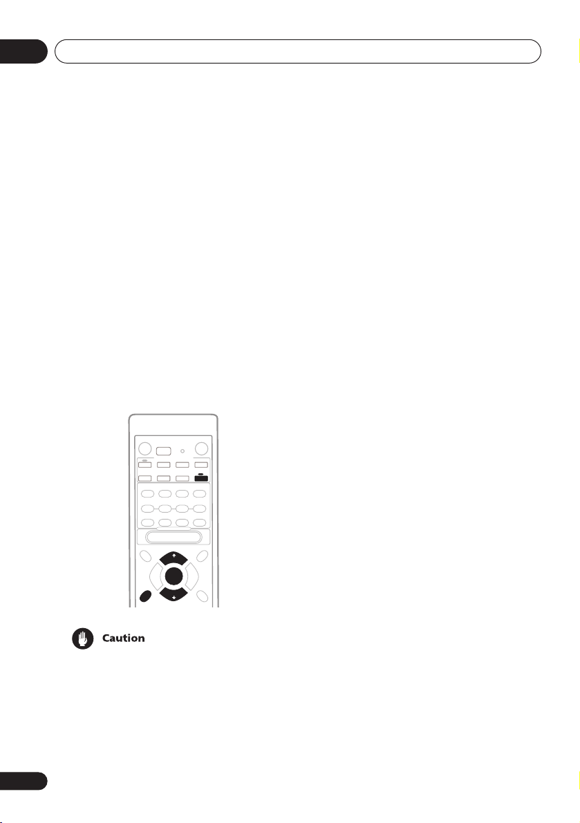
Use the front panel controls for the steps
below.
STEREO/
DVANCED
URROUND
DIRECT
ENING MODE
L DIMMER
Quick surround sound setup
Choosing your receiver setup
ENTER
SIGNAL
MIDNIGHT/
LOUDNESS
SPEAKERS
DIGITAL IN
MONITOR T ONE QUICK SETUP
MULTI JOG
VIDEO INPUT
S-VIDEO VIDEO L AUDIO R
DOWN UP
SELECT
on
on
MULTI JOG
MASTER VOLUME
R
3 Use the MULTI JOG dial to choose your
speaker setup.
When a subwoofer was detected in step 2, you
can cycle between the following choices:
2.1ch 3.1ch
7.1ch*
4.1ch
6.1ch 5.1ch
*
VSX-D812/D912 only
If a subwoofer wasn’t detected in step 2, you
can cycle between the following choices:
2.0ch 3.0ch
7.0ch*
4.0ch
6.0ch 5.0ch
*
VSX-D812/D912 only
• Check the table below to find the speaker
setup that corresponds with your system.
1 If the receiver is off, press
STANDBY/ON to turn the power on.
The
STANDBY
indicator goes out.
2 Press QUICK SETUP.
SW DET
flashes in the display while the
receiver checks your setup for a subwoofer.
SW YES
or
SW NO
confirms the subwoofer
check, then the display prompts you to select
your speaker setup.
12
En
*
VSX-D812/D912 only
Page 13

5 minute guide
02
4 Press ENTER.
5 Use the MULTI JOG dial to choose your
room size.
Depending on the distance of your speakers
from the listening position, choose between
small, medium, or large (
an average-sized room.
6 Press ENTER.
7 Use the MULTI JOG dial to choose your
listening position.
You can cycle between the following choices:
FWD
BACK
FWD
– If you are nearer to the front
speakers than the surround speakers
MID
– If you are equal distance from the
front and surround speakers
BACK
– If you are nearer to the surround
speakers than the front speakers
8 Press ENTER to confirm your setup.
The display shows the speaker setup, room
size and listening position that you have
selected.
S, M
or L), M being
MID
English Italiano Français
Nederlands
EspañolDeutsch
13
En
Page 14
03
Quick surround sound setup
Chapter 3:
Quick surround sound setup
VSX-D912 only
Automatically calibrating
your listening area (MCACC)
The Multi-Channel Acoustic Calibration
(MCACC) system measures the acoustic
characteristics of your listening area, taking
into account ambient noise, speaker size and
distance, and tests for both channel delay and
channel level. After you have set up the
microphone provided with your system, the
receiver uses the information from a series of
test tones to optimize the speaker settings
and equalization for your particular room.
RECEIVER
ENTER
MCACC
SETUP
• These test tones can be loud, so take care
that there is no one in the room who will
be startled by the noise.
• Make sure the mic and speakers are not
moved during the MCACC setup.
14
En
1 Connect the microphone to the SETUP
MIC jack on the front panel.
2 Place the microphone at your normal
listening position.
Place the mic about ear level at your normal
listening position using the supplied microphone stand on a table or chair.
Make sure there are no obstacles between the
speakers and the microphone.
3 If the receiver is off, press
STANDBY/ON to turn the power on.
The
STANDBY
4 If you have a subwoofer, turn it on.
5 Press RECEIVER.
6 Press MCACC SETUP.
Try to be as quiet as possible after pressing
MCACC SETUP
of test tones to establish the ambient noise
level.
If the noise level is too high,
the display for five seconds. To exit and check
the noise levels again, press
(see the notes regarding ambient noise levels
below) or press
to
GO NEXT?
The system now checks the microphone and
your speaker setup.
If you see an
there may be a problem with your mic or the
speaker connections.
Turn off the power, and check the problem
indicated by the
then try the auto surround setup again.
•
ERR MIC
connection.
indicator goes out.
. The system outputs a series
NOISY!
blinks in
MCACC SETUP
ENTER
when you’re prompted
ERR
message in the display,
ERR
message (see below),
– Check the microphone
Page 15

Quick surround sound setup
•
ERR Fch
connections.
•
ERR Sch
surround back speaker connections.
•
ERR SW
been switched on and volume on the
subwoofer is turned up.
7 Use and to select the speaker
system that corresponds to your setup.
Cycle between the following choices:
7.1ch*
7.0ch
* Indicates a subwoofer is included in your
speaker setup
See the table on page 12 if you’re unsure
which speaker system to select.
8 If you selected a speaker system that
includes a subwoofer, press ENTER to
check the subwoofer output level.
If the subwoofer output level is too high/low,
SW.VOL.UP/SW.VOL.DWN
display for five seconds. To exit and check
your subwoofer output level, press
SETUP
below) or simply turn the subwoofer volume
up or down (as indicated), then press
when you’re prompted to
9 Press ENTER to finish the auto
surround setup.
The system checks for speaker size, channel
delay and channel level. If you have
connected a subwoofer, it will check for
ambient noise once again.
When the auto surround setup is complete,
the volume level returns to normal and
COMPLETE
display.
– Check the front speaker
– Check the surround or
– Make sure the subwoofer has
2.0ch 2.1ch* 3.1ch*3.0ch
4.0ch
4.1ch*
6.1ch* 6.0ch 5.0ch5.1ch*
blinks in the
MCACC
(see the notes regarding noise levels
ENTER
GO NEXT?
, then
RESUME
shows in the
• If the room environment is not optimal for
the auto surround setup (too much
ambient noise, echo off the walls, obstacles blocking the speakers from the
microphone) the final settings may be
incorrect. Check for household appliances (air conditioner, fridge, fan, etc.),
that may be affecting the environment
and switch them off if necessary.
• Some older TVs may interfere with the
operation of the mic. If this seems to be
happening, switch off the TV when doing
the auto surround setup.
• Using the MCACC system to set up your
speaker system overwrites any previous
settings you had for the
ADVANCED SURROUND
• When the
SURROUND
check the settings made with MCACC by
using
levels) or by going through the steps in
Choosing your receiver setup
to check other settings.
• Depending on the the characteristics of
your room, sometimes identical speakers
with cone sizes of around 12cm will end
up with different size settings. You can
correct the setting manually using the
receiver setup on page 43.
STANDARD
mode is selected, you can
CH SELECT
STANDARD
modes.
or
ADVANCED
(to check channel
03
English Italiano Français
or
on page 43
Nederlands
EspañolDeutsch
15
En
Page 16

04
Connecting up
Chapter 4:
Connecting up
• Before making or changing any
connections, switch off the power and
disconnect the power cord from the AC
outlet.
Audio/Video cords
Use audio/video cords (not supplied) to
connect the audio/video components and a
video cord to connect the monitor TV.
Connect red plugs to R (right), white plugs to
L (left), and the yellow plugs to
Be sure to insert completely.
R
VIDEO
L
VIDEO
Component video cords
Use component video cords to get the best
possible color reproduction of your video
source. The color signal of the TV is divided
into the luminance (
(
PB
and PR) signals and then output. In this
way, interference between the signals is
avoided. Connect from the component video
jacks on the rear of the receiver to the component video jacks on the video component you
are hooking up.
.
Green
Y
) signal and the color
Y
P
Blue
Red
B
P
R
S-video cables
Use S-video cables (not supplied) to get
clearer picture reproduction than regular
video cords.
Connect from an S-video jack on the rear of
the receiver to an S-video jack on the video
component you are hooking up.
Be sure to insert completely.
S VIDEO
16
En
Digital audio coaxial cords/
Optical cables
Commercially available digital audio coaxial
cords (standard video cords can also be used)
or optical cables (not supplied) are used to
connect digital components to this receiver.
Be sure to insert completely.
Digital audio coaxial cord
(or standard video cord)
Optical cable
Page 17
Connecting up
R
N
O
04
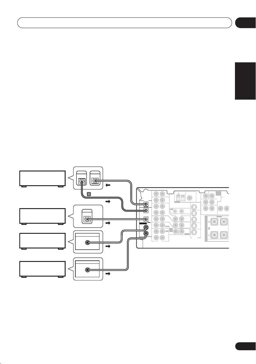
Connecting digital components
The easiest way to hook up this receiver for surround sound is to use a digital input. You can do
this by either coaxial or optical connections (you do not need to do both). The quality of these
two types of connections is the same but since some digital components only have one type of
digital terminal, it is a matter of matching like with like (for example, the coaxial output from the
component to coaxial input on the receiver). The VSX-D712 has three digital inputs on the rear
panel (two coaxial inputs and an optical input) and both the VSX-D812 and VSX-D912 have four
(two coaxial inputs and two optical inputs). Connect your digital components to the rear panel
as shown below.
There is one digital output jack which is marked
input on a digital recorder (currently these include MD, DAT and CD-R) you can make direct
digital recordings with this unit.
When connecting your equipment, always make sure the power is turned off and the power cord
is disconnected from the AC outlet.
• The arrows indicate the direction of the digital audio signal.
DIGITAL
CD recorder
Satellite tuner
CD player
DIGITAL
IN
OUT
VSX-D912/D812 only
DIGITAL
OUT
DIGITAL OUT
COAX
DIGITAL OUT
This receiver*
DIGITAL
OUT
OPT
OPT
2
(CD-R/TAPE/MD)
OPT
1
(TV/
SAT)
ASSIGNABLE
COAX
DIGITAL
2
IN
(CD)
COAX
1
(DVD
/LD)
. If you connect this to the optical
CEN-
R
OUT
IN
TV/
SAT
IN
IN
DVD
SUB W.
TER
7.1CH
INPUT
SURROUND
LR
L
SURROUND BACK
RL
S
P
E
A
A
K
E
R
S
FRONT
AM
FM UNBAL
LOOP
Ω
ANTENNA
OUT IN
VIDEO
IN
IN
D V D
7.1CH
INPUT
IN
75
CONTROL
OUT
MONITOR
OUT
SUB
WOOFER
PREOUT
MONITOR OUT
S-VIDEO
VCR/
DVR
DVD/
LD
AUX
IN
CD
IN
VCR/
OUT
DVR
IN
TV/
SAT
IN
DVD
/ LD
FRONT
IN
REC
CD-R
OUT
/ TAPE
/ MD
IN
PLAY
R
L
AUDIO
COMPO
MONITO
YP
English Italiano Français
VIDE
B
Nederlands
DVD player
*
The illustration shows the VSX-D812/D912, but connections for the VSX-D712 are the same.
DIGITAL OUT
COAX
EspañolDeutsch
17
En
Page 18
04
L
C
OUTPUT
Connecting up
• If you have an LD player, you need to make special connections to ensure you can play 2
RF format LDs on your system. If this is the case, hook up your DVD or LD player directly to
an RF demodulator using both the
2
RF output and either a coaxial or optical digital
connection. We also recommend hooking up your digital components to analog audio jacks
as well. Make sure the RF demodulator digital in switch is set correctly (optical or coaxial
depending on the connection). See the component's instruction manual if you are unsure
about its input and output jacks.
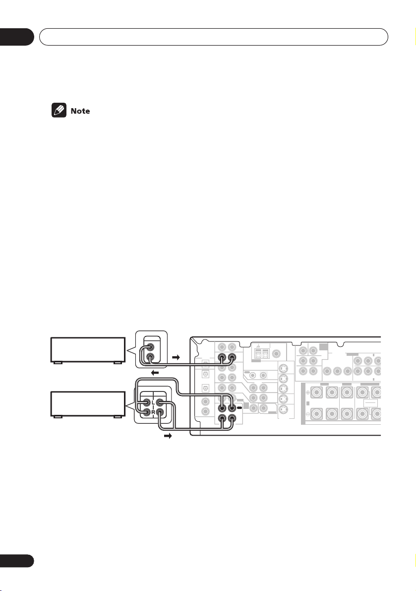
Connecting audio components
To begin set up, connect your analog audio components (such as a cassette deck) to the jacks.
For components you want to record with, you need to hook up four plugs to the receiver (a set
of stereo inputs and a set of stereo outputs), but for components that only play, you only need
to hook up one set of stereo plugs. You must also hook up your digital components to analog
audio jacks if you want to record to/from digital components (like an MD) to/from analog
components. See page 17 for more on digital connections.
When connecting your equipment, always make sure the power is turned off and the power cord
is disconnected from the AC outlet.
• The arrows indicate the direction of the audio signal.
18
En
This receiver*
Ω
MONITOR OUT
S-VIDEO
OUT
VCR/
DVR
IN
TV/
SAT
IN
DVD/
LD
IN
CEN-
DVD
SUB W.
TER
7.1CH
INPUT
SURROUND
LR
LR
SURROUND BACK
RL
S
P
E
A
A
K
E
R
S
COMPONENT
VIDEO
MONITOR OUT
YP
FRONT
BPR
ASSIGNABLE
CENTER
AM
ANTENNA
OUT IN
VIDEO
IN
IN
D V D
7.1CH
INPUT
IN
FM UNBAL
LOOP
75
CONTROL
OUT
MONITOR
OUT
SUB
WOOFER
PREOUT
CD player
DIGITAL
OUT
(CD-R/TAPE/MD)
CD-R/Tape/MD deck
*
The illustration shows the VSX-D812/D912, but connections for the VSX-D712 are the same.
RE
ASSIGNABLE
DIGITAL
IN
AUX
IN
CD
IN
OPT
OPT
VCR/
OUT
DVR
2
IN
OPT
1
TV/
SAT
(TV/
IN
SAT )
COAX
DVD
/ LD
2
FRONT
IN
(CD)
COAX
REC
1
CD-R
OUT
(DVD
/ TAPE
/LD)
/ MD
IN
PLAY
R
L
AUDIO
(DVD/LD) IN 1
YPBP
(TV/SAT) IN 2
SURROUND BACK
R
SINGLE
SEE INSTRUCTION
MANUAL
R
Page 19

Connecting up
04
Connecting DVD multi-channel components
If you prefer to use a seperate component for decoding DVDs, you can connect a decoder or a
DVD player with multi-channel analog outputs to the multi-channel inputs of this receiver.
When connecting your equipment, always make sure the power is turned off and the power cord
is disconnected from the AC outlet.
• The arrows indicate the direction of the signal.
CEN-
AM
FM UNBAL
LOOP
Ω
DIGITAL
OUT
(CD-R/TAPE/MD)
ASSIGNABLE
DIGITAL
IN
AUX
IN
CD
IN
OPT
OPT
VCR/
OUT
DVR
2
IN
OPT
1
TV/
SAT
(TV/
IN
SAT )
COAX
DVD
/ LD
2
FRONT
IN
(CD)
COAX
REC
1
CD-R
OUT
(DVD
/ TAPE
/LD)
/ MD
IN
PLAY
R
L
AUDIO
ANTENNA
OUT IN
VIDEO
IN
IN
D V D
7.1CH
INPUT
IN
75
CONTROL
OUT
MONITOR
OUT
SUB
WOOFER
PREOUT
MONITOR OUT
S-VIDEO
This receiver*
*
The illustration shows the VSX-D812/D912, but connections for the VSX-D712 are the same.
• The multi-channel input can only be used when
D812/D912) is selected (see page 42).
VSX-D812/D-912 only
• If the component you are connecting only has one surround back channel output, change
the Surround back channel input setting (page 49) to
DVD
SUB W.
TER
7.1CH
INPUT
SURROUND
LR
L
R
SURROUND BACK
OUT
VCR/
DVR
DVD/
LD
FRONT
RL R
S
IN
P
E
TV/
SAT
A
IN
A
K
E
IN
R
S
PREOUT
SURROUND
LL
BACK
VSX-D812/D912 only
RR
SURROUND
FRONT CENTER
SURROUND BACK
FRONT
OUTPUT
L
R
LR L
RL
SINGLE
SEE INSTRUCTION
MANUAL
DVD/multi-channel decoder
with multi-channel analog
output jacks
DVD 5.1 ch
SB 1ch IN
FRONTCENTER SURROUND
SURROUND
SURROUND
BACK OUTPUT
OUTPUT
L
B
R
(VSX-D712) or
SUB
CENTER
WOOFER
OUTPUT
L
OUTPUT
VIDEO
OUTPUT
R
DVD 7.1 ch
(VSX-
.
English Italiano Français
Nederlands
EspañolDeutsch
19
En
Page 20

04
C
Connecting up
Connecting video components
Connect your video components to the jacks as shown below. With digital video components
(like a DVD player), you must use the connections shown on this page for the video signal, but
in order to hear a digital source (like a DVD) you should hook up the audio to a digital input (see
page 17). It is also a good idea to hook up your digital components with analog audio
connections (see page 18).
For better quality video, you can hook up using the component video jacks or the S-video jacks
(quality descends in this order) on the rear of the receiver instead of the regular video jacks.
Make sure they are connected to the video component using the same kind of connection.
When connecting your equipment, always make sure the power is turned off and the power cord
is disconnected from the AC outlet.
• The arrows indicate the direction of the signal
Video deck
INPUT
VIDEO
L
R
LR
BACK
LR
CENTER SURROUND
FRONT
INPUT
VIDEO
TV tuner
(or Satellite tuner)
DVD or LD player
OUTPUT
VIDEO
OUTPUT
VIDEO
This receiver*
CEN-
AM
FM UNBAL
LOOP
Ω
ANTENNA
OUT IN
VIDEO
IN
IN
D V D
7.1CH
INPUT
IN
75
CONTROL
OUT
MONITOR
OUT
SUB
WOOFER
PREOUT
MONITOR OUT
S-VIDEO
L
R
L
DIGITAL
OUT
(CD-R/TAPE/MD)
ASSIGNABLE
DIGITAL
IN
CD
IN
OPT
OPT
VCR/
OUT
DVR
2
IN
OPT
1
TV/
SAT
(TV/
IN
SAT )
COAX
DVD
/ LD
2
FRONT
IN
(CD)
COAX
REC
1
CD-R
OUT
(DVD
/ TAPE
/LD)
/ MD
IN
PLAY
R
L
AUDIO
AUX
IN
R
SUB WOOFER
TER
SURROUND
SURROUND
DVD 7.1CH INPUT
OUT
VCR/
RL R
DVR
S
IN
P
E
TV/
SAT
A
IN
A
K
DVD/
LD
E
IN
R
S
OUTPUT
VIDEO
L
R
SURROUND BACK
RL
SINGLE
SEE INSTRUCTION
MANUAL
LL
RR
FRONT CENTER
SURROUND
PREOUT
SURROUND
L
BACK
TV (monitor)
*
The illustration shows the VSX-D812/D912, but connections for the VSX-D712 are the same.
Connecting to the front panel video
terminal
Front video connections are accessed via the
front panel using the
standard audio/video jacks as well as an
S-video jack (the VSX-D912 also has an optical
VIDEO
button. There are
O/
SIGNAL
MIDNIGHT/
T
SPEAKERS
SELECT
LOUDNESS
SETUP
DIGITAL IN
MIC
S-VIDEO VIDEO L AUDIO R
input). Hook them up the same way you made
the rear panel connections.
DIGITAL OUT
SB CH
TONE
MODE
MULTI JOG
VIDEO INPUT
LV
VIDEO OUTPUT
QUICK
SETUP
Video
camera
(etc.)
R
20
En
Page 21

Connecting up
04
Connecting antennas
Connect the AM loop antenna and the FM
wire antenna as shown below. To improve
reception and sound quality, connect external
antennas (see
below). Always make sure that the receiver is
switched off and unplugged from the wall
outlet before making or changing any
connections.
(CD-R/TAPE/MD)
ASSIGNABLE
DIGITAL
IN
FM wire antenna
Connect the FM wire antenna and fully extend
vertically along a window frame or another
suitable place that gives good reception.
AM loop antenna
Assemble the antenna and connect to the
receiver. Attach (if necessary) and face in the
direction that gives the best reception.
Using external antennas
AM loop
antenna
AUX
IN
DIGITAL
OUT
CD
IN
OPT
OPT
OUT
2
IN
OPT
1
(TV/
IN
SAT)
COAX
2
IN
(CD)
COAX
1
OUT
(DVD
/LD)
IN
R
ANTENNA
VCR/
OUT IN
DVR
VIDEO
IN
TV/
SAT
IN
DVD
/ LD
FRONT
D V D
7.1CH
INPUT
REC
IN
CD-R
/ TAPE
/ MD
PLAY
L
AUDIO
FM wire
CEN-
OUT
VCR/
DVR
IN
TV/
SAT
IN
DVD/
LD
IN
SUB WOOFER
TER
antenna
SURROUND
LR
SURROUND
BACK
LR
DVD 7.1CH INPUT
FRONT
RL
S
P
E
A
A
K
E
R
S
AM
FM UNBAL
LOOP
75
Ω
MONITOR OUT
CONTROL
OUT
MONITOR
OUT
SUB
WOOFER
PREOUT
S-VIDEO
Antenna snap connectors
Twist the exposed wire strands together and
insert into the hole, then snap the connector
shut.
10mm
Using external antennas
To improve FM reception
Connect an external FM antenna.
FM UNBAL
75
Ω
Outdoor
antenna
75Ω coaxial
cable
AM
FM UNBAL
LOOP
75
Ω
5–6m
Indoor antenna
(vinyl-coated wire)
One-touch
PAL connector
AM
LOOP
ANTENNA
To improve AM reception
Connect a 5–6 metre length of vinyl-coated
wire to the AM antenna terminal without
disconnecting the supplied AM loop antenna.
For the best possible reception, suspend
horizontally outdoors.
English Italiano Français
Nederlands
EspañolDeutsch
ANTENNA
21
En
Page 22

04
OOP
UNBAL
OUT
MONITOR OUT
COMPONENT
VIDEO
er
Connecting up
Connecting the speakers (VSX-D712)
A complete setup of six speakers (including the subwoofer) is shown below, but everyone’s
home setup will vary. Simply connect the speakers you have in the manner shown below. The
receiver will work with just two stereo speakers (the front speakers in the diagram) but using at
least three speakers is recommended, and a complete setup is best. If you’re not using a
subwoofer, change the front speaker setting (see
Make sure you connect the speaker on the right to the right terminal and the speaker on the left
to the left terminal. Also make sure the positive and negative (
match those on the speakers.
Be sure to complete all connections before connecting this unit to the AC power source.
Speaker setting
+/–
on page 44) to large.
) terminals on the receiver
• Use speakers with a nominal impedance of 8
Front speakers
LR C LSRS
L
MONITOR OUT
SURROUND
CONTROL
OUT
MONITOR
OUT
SUB
WOOFER
PREOUT
SURROUND
BACK
S-VIDEO
DVD 5.1CH INPUT
OUT
VCR/
DVR
IN
TV/
SAT
IN
DVD/
LD
IN
YPBPRYPBP
FRONT
RL R LRL
S
P
E
A
A
K
E
R
S
ASSIGNABLE
DIGITAL
IN
VCR/
OUT
OUT IN
DVR
IN
OPT
1
(TV/
IN
SAT )
COAX
2
IN
(CD)
COAX
1
OUT
(DVD
/LD)
IN
R
VIDEO
IN
TV/
SAT
IN
DVD
/ LD
FRONT
D V D
5.1CH
INPUT
REC
IN
CD-R
/ TAPE
/ MD
PLAY
L
AUDIO
Poweredwoof
Ω
to 16 Ω.
Surround speakersCenter speaker
(TV/SAT) IN 2
R
FRONTCENTER SURROUND
B
VSX-D712
22
En
Page 23

Connecting up
04
Connecting the speakers (VSX-D812/D912)
A complete setup of eight speakers (including the subwoofer) is shown below, but everyone’s
home setup will vary. Simply connect the speakers you have in the manner shown below. The
receiver will work with just two stereo speakers (the front speakers in the diagram) but using at
least three speakers is recommended, and a complete setup is best for surround sound. If
you’re not using a subwoofer, change the front speaker setting (see
to large.
Make sure you connect the speaker on the right to the right terminal and the speaker on the left
to the left terminal. Also make sure the positive and negative (
match those on the speakers.
Be sure to complete all connections before connecting this unit to the AC power source.
• Use speakers with a nominal impedance of 8
Front speakers
LR C LSRS
AUX
IN
DIGITAL
OUT
CD
IN
OPT
OPT
VCR/
OUT
OUT IN
DVR
2
(CD-R/TAPE/MD)
IN
ASSIGNABLE
DIGITAL
IN
OPT
1
(TV/
SAT)
COAX
2
(CD)
COAX
1
(DVD
/LD)
IN
TV/
SAT
IN
IN
DVD
/ LD
FRONT
IN
D V D
7.1CH
INPUT
REC
IN
CD-R
OUT
/ TAPE
/ MD
IN
PLAY
R
L
AUDIO
ANTENNA
AM
LOOP
CONTROL
VIDEO
OUT
MONITOR
OUT
SUB
WOOFER
PREOUT
Center speaker
CEN-
FM UNBAL
75
Ω
MONITOR OUT
S-VIDEO
OUT
VCR/
DVR
IN
TV/
SAT
IN
DVD/
LD
IN
TER
R
SURROUND BACK
S
P
E
A
A
K
E
R
S
SUB W.
DVD
7.1CH
INPUT
COMPONENT
VIDEO
SURROUND
MONITOR OUT
LR
L
BPR
FRONT
RL R LRL
Ω
to 16 Ω.
Surround speakers
ASSIGNABLE
(DVD/LD) IN
1
L L
RRYP
YPBP
R
(TV/SAT) IN 2
FRONT CENTER
SURROUND BACK
RL
SINGLE
SEE INSTRUCTION
MANUAL
SURROUND
SURROUND
BACK
VSX-D812/D912
Passive
INPUT
subwoofer
or single
surround
back
speaker
Powered subwoofer
SW
Speaker setting
+/–
) terminals on the receiver
Surround back speakers
SBL SBR
FRONTCENTER SURROUND
B
TV
on page 44)
English Italiano Français
Nederlands
EspañolDeutsch
23
En
Page 24

04
Connecting up
• When using the speaker on your TV as the
center speaker (
PREOUT
input jack on your TV. In this case the
center speaker shown is unnecessary.
• If you are using only one surround back
speaker, connect the positive wire to the
right channel (
negative wire to the left channel (
terminal (see illustration on page 11).
• If you select subwoofer (
Surround back speaker setting
you can hook up a subwoofer instead of
speakers to the surround back speaker
terminals. Connect the positive wire to the
right channel (
negative wire to the left channel (
terminal (see illustration on page 11).
C
), connect the
jack on this unit to the audio
+
) terminal, and the
+
) terminal, and the
SB SW
CENTER
–
)
) in the
on page 45
–
)
Speaker terminals
12 3
10mm
1 Twist exposed wire strands together.
2 Loosen speaker terminal and insert
exposed wire.
Make sure that all the bare speaker wire is
twisted together and inserted fully into the
speaker terminal. If any of the bare speaker
wire is touching the back panel when you
switch the unit on, the power may cut off as a
safety measure. Use good quality speaker
wire to connect the speakers to the receiver.
3 Tighten terminal.
• These speaker terminals are hazardous
when live. To prevent the risk of electric
shock when connecting or disconnecting
the speaker cables, disconnect the power
cord.
A and B speaker systems
The receiver has two speaker systems: A and
B. A is the main system supporting the full
speaker setup. If you switch on both A and B
speaker systems, only the front speakers and
the (active) subwoofer will be audible. No
sound will come from the center, surround, or
surround back speakers, but multi-channel
sources will be down-mixed to the active
speakers so no sound will be lost. Similarly, if
you choose just the B system you‘ll only hear
the front speakers connected to the B system
and multi channel sources will be downmixed to these two speakers.
• Press the SPEAKERS button on the
front panel to switch between speaker
systems (A, B or both).
Hints on speaker placement
Speakers are usually designed with a
particular placement in mind. Some are
designed to be floorstanding, while others
should be placed on stands to sound their
best. Some should be placed near a wall;
others should be placed away from walls. We
have provided a few tips on getting the best
sound from your speakers (following), but you
should also follow the guidelines on
placement that the speaker manufacturer
provided with your particular speakers to get
the most out of them.
• Place the front left and right speakers at
equal distances from the TV.
24
En
Page 25

Connecting up
04
• When placing speakers near the TV, we
recommend using magnetically shielded
speakers to prevent possible interference,
such as discoloration of the picture when
the TV is switched on. If you do not have
magnetically shielded speakers and
notice discoloration of the TV picture,
move the speakers farther away from the
TV.
• Place the center speaker above or below
the TV so that the sound of the center
channel is localized at the TV screen.
• If possible, place the surround speakers
slightly above ear level.
• Try not to place the surround speakers
further away from the listening position
than the front and center speakers. Doing
so can weaken the surround sound effect.
• To achieve the best possible surround
sound, install your speakers as shown
below. Be sure all speakers are installed
securely to prevent accidents and
improve sound quality.
• If you choose to install the center speaker
on top of the TV, be sure to secure it with
putty, or by other suitable means, to
reduce the risk of damage or injury
resulting from the speaker falling from the
TV in the event of external shocks such as
earthquakes.
Overhead view of speaker setup
Front
Left
Surround
Left
Listening Position
Surround Back Surround Back
3-D view of
3-D view of
Left Right
Single Surround Back Speaker
6.1 channel
7.1 channel
Front
RightCenter
Subwoofer
Surround
Right
speaker setup
speaker setup
English Italiano Français
Nederlands
EspañolDeutsch
25
En
Page 26

04
Connecting up
Connecting additional amplifiers
This receiver has more than sufficient power for any home use, however it is possible to add
additional amplifiers to every channel on the VSX-D812/D912 or the surround back channel of
the VSX-D712. Make the connections shown below to add amplifiers to power your speakers.
Always make sure that the receiver is switched off and unplugged from the wall outlet before
making or changing any connections.
• The arrows indicate the direction of the audio signal.
VSX-D712
CEN-
DIGITAL
ASSIGNABLE
DIGITAL
IN
AM
FM UNBAL
LOOP
Ω
ANTENNA
OUT IN
VIDEO
IN
IN
D V D
5.1CH
INPUT
IN
75
CONTROL
OUT
MONITOR
OUT
SUB
WOOFER
PREOUT
SURROUND
BACK
OUT
CD
IN
OPT
VCR/
OUT
DVR
IN
OPT
1
TV/
SAT
(TV/
IN
SAT )
COAX
DVD
/ LD
2
FRONT
IN
(CD)
COAX
REC
1
CD-R
OUT
(DVD
/ TAPE
/LD)
/ MD
IN
PLAY
R
L
AUDIO
AUX
IN
MONITOR OUT
S-VIDEO
SUB WOOFER
TER
LR
SURROUND
DVD 5.1CH INPUT
OUT
VCR/
DVR
IN
TV/
SAT
IN
DVD/
LD
IN
FRONT
RL R LRL
S
P
E
A
A
K
E
R
S
INPUT
ANALOG IN
FRONTCENTER SURROUND
B
Surround back
channel amplifier
or powered speaker
Powered
subwoofer
26
En
VSX-D812/D912
OPT OPT
AUX
IN
DIGITAL
(
(
CD-R/
TV/
OUT
¥
ø
)
CD
SAT
IN
/ TAPE
OPT
)
/ MD
OPT
VCR/
OUT
DVR
2
(CD-R/TAPE/MD)
IN
OPT
RL
S
1
TV/
SAT
(TV/
P
IN
SAT)
ASSIGNABLE
DIGITAL
IN
E
COAX
DVD
/ LD
2
A
FRONT
IN
(CD)
A
K
COAX
REC
1
E
CD-R
OUT
(DVD
/ TAPE
/LD)
R
/ MD
S
IN
PLAY
R
L
AUDIO
AM
FM UNBAL
LOOP
75
Ω
COMPONENT
ASSIGNABLE
ASSIGNABLE
VIDEO
COMPONENT
12
VIDEO
MONITOR OUT
DIGITAL OUT
ANTENNA
MONITOR OUT
MONITOR OUT
OUT IN
YPBPRYP
BPR
YP
P
CONTROL
VIDEO
FRONT
CENTER
R
OUT
MONITOR
OUT
SUB
WOOFER
PREOUT
R
S-VIDEO
IN
IN
D V D
7.1CH
INPUT
IN
LL
B
B
RR
FRONT CENTER
SURROUND
OUT
VCR/
SURROUND BACK
R
RL
DVR
IN
TV/
SAT
SINGLE
IN
IN
SEE INSTRUCTION
MANUAL
DVD/
LD
IN
SURROUND
BACK
FRONTSURROUND
LR L
B
ANALOG IN
L R
ANALOG IN
R
L
ANALOG IN
ANALOG IN
INPUT
Powered
subwoofer
Front channel
amplifier
Surround channel
amplifier
Surround back
channel amplifier
Center channel
amplifier
Page 27

Connecting up
04
• To hear sound only from the pre-outs,
disconnect any speakers that are
connected directly to the receiver.
• If you’re not using a subwoofer, change
the front speaker setting (see
setting
on page 44) to large.
•
VSX-D712 only –
If you connect to a
Speaker
surround back speaker, make sure the
Surround back speaker setting
on page 45
is switched on and set to the proper
speaker size.
Power cord caution
Handle the power cord by the plug. Do not
pull out the plug by tugging the cord and
never touch the power cord when your hands
are wet as this could cause a short circuit or
an electric shock. Do not place the unit, a
piece of furniture, etc., on the power cord, or
pinch the cord. Never make a knot in the cord
or tie it with other cords. The power cords
should be routed such that they are not likely
to be stepped on. A damaged power cord can
cause a fire or give you an electrical shock.
Check the power cord once in a while. When
you find it damaged, ask your nearest Pioneer
authorized service center or your dealer for a
replacement.
Operating other Pioneer
components
By connecting a control cord (optional), you
can point the remote controls of other Pioneer
components at the receiver’s remote sensor.
The remote control signals are received by the
remote sensor of this unit, and sent to the
other devices via the
of the receiver.
OUT IN
CONTROL
Receiver
Remote
control
unit
CONTROL OUT
CONTROL
IN
OUT
Other Pioneer products
with CONTROL terminals
Connect to CONTROL
terminal of other
compatible Pioneer products
terminal
English Italiano Français
Nederlands
EspañolDeutsch
27
En
Page 28

05
O
Controls and displays
Chapter 5:
Controls and displays
Front panel
DVD/LDTV/SATVCR/DVRVIDE
CD-R/
CD
AUX
TAPE/MD
TUNER
STANDBY
STANDBY/ON
PULL OPEN
PHONES
8
10 11 12 13 14 15 16 17
9
MPX
ADVANCED
SURROUND
PHONES SURR.
LISTENING MODE
INPUT ATT FL DIMMER
STATION STANDARD SPEAKERS
TUNING
TUNER EDIT
MULTI JOG
BAND
CLASS
26 25 24 23 22 21 18
1 STANDBY/ON
Switches the receiver between on and
standby.
2 Input select buttons
Press to select an input source.
3 STANDBY indicator
Lights when the receiver is in standby.
4 Remote sensor
Receives the signals from the remote control.
4
5 6
ENTER
DOWN UP
MULTI JOG
MASTER VOLUME
7
STEREO/
SIGNAL
MIDNIGHT/
DIRECT
SELECT
LOUDNESS
SETUP
DIGITAL IN
MIC
SB CH
TONE
MODE
MULTI JOG
VIDEO INPUT
S-VIDEO VIDEO L AUDIO R
QUICK
SETUP
1920
5 ENTER
6 MULTI JOG dial
The
MULTI JOG
dial performs a number of
tasks. Use it to select options after pressing
TONE, QUICK SETUP
or
TUNER EDIT
7 MASTER VOLUME
8 PHONES jack
Use to connect headphones. When the
headphones are connected, there is no sound
output from the speakers.
.
28
En
Page 29

Controls and displays
05
9 STATION +/– buttons
Selects station presets when using the tuner
(page 54).
10 TUNING +/– buttons
Selects the frequency when using the tuner
(page 53).
11 LISTENING MODE buttons
STANDARD
Press for Standard decoding and to
switch between the various Pro Logic II
and Neo:6 options (page 37).
ADVANCED SURROUND
Use to switch between the various
surround modes
STEREO/DIRECT
Switches between direct and stereo
playback. Direct playback bypasses the
tone controls and channel levels for the
most accurate reproduction of a source
(page 38).
12 SIGNAL SELECT
Use to select an input signal (page 36).
13 MIDNIGHT/LOUDNESS
Use Midnight when listening to movie
soundtracks at low volume. Use Loudness to
boost the bass and treble at low volume
(page 41).
14 SPEAKERS
Use to cycle through the speaker system:
A B A+B
15 SB CH MODE
Selects the Surround back channel mode
(page 39) and the Virtual Surround Back
(VSB) mode (page 40).
16 TONE
Press this button to access the bass and
treble controls, which you can then adjust
with the
(page 24)
MULTI JOG
(page 38).
dial (page 41).
17 QUICK SETUP
See
Using the Quick Setup
18 VIDEO INPUT
See
Connecting to the front panel video
terminal
19 DIGITAL IN
VSX-D912 only
See
terminal
20 SETUP MIC
VSX-D912 only
Connect the microphone supplied with your
system to the
auto surround setup (MCACC)
21 FL DIMMER
Use this button to make the fluorescent
display (FL) dimmer or brighter.
22 INPUT ATT
Use to attenuate (lower) the level of an analog
input signal to prevent distortion.
23 MPX
Press to receive a radio broadcast in mono
(page 53).
24 BAND
Switches between AM and FM radio bands
(page 53).
25 CLASS
Switches between the three banks (classes)
of station presets
26 TUNER EDIT
Press to memorize and name a station for
recall
on page 20.
Connecting to the front panel video
on page 20.
SETUP MIC
(page 54).
(page 54).
on page 12.
jack when using the
(page 14).
English Italiano Français
Nederlands
EspañolDeutsch
29
En
Page 30

05
Controls and displays
Display
123457689 10
11
12 15
1 SIGNAL SELECT indicators
Lights to indicate the type of input signal
assigned for the current component:
AUTO
Lights when
SB
Depending on the source, this lights
when a signal with surround back
channel encoding is detected.
DIGITAL
Lights when a digital audio signal is
detected.
2
DIGITAL
Lights when a Dolby Digital encoded
signal is detected.
ANALOG
Lights when an analog signal is detected.
DTS
Lights when a source with DTS encoded
audio signals is detected.
2 DTS
When the
on, this lights to indicate decoding of a DTS
signal.
AUTO
STANDARD
signal select is on.
mode of the receiver is
13
3
2
DIGITAL
When the
on, this lights to indicate decoding of a Dolby
Digital signal.
4
When the (
the receiver is on, this lights to indicate Pro
Logic II decoding.
5 VIR.SB
Lights during Virtual surround back
processing.
6 ATT
Lights when
(reduce) the level of the analog input signal.
7 DIRECT
Lights when source direct playback is in use.
Direct playback bypasses the tone controls
and channel levels for the most accurate
reproduction of a source.
8 MIDNIGHT
Lights during Midnight listening.
9 SLEEP
Lights when the receiver is in sleep mode.
10 Speaker indicator
Shows the speaker system currently in use.
STANDARD
2
PRO LOGIC II
STANDARD
INPUT ATT
mode of the receiver is
1614
) Pro Logic II mode of
is used to attenuate
30
En
Page 31

Controls and displays
05
11 Character display
12 Neo:6
When the (
receiver is on, this lights to indicate NEO:6
processing.
13 ADV.SURR. (Advanced Surround)
Lights when one of the Advanced Surround
modes has been selected.
14 LOUDNESS
Lights when
15 TUNER indicators
16 Master volume level
Shows the overall volume level.
indicates the minimum level, and
indicates the maximum level.
Depending on your level settings for each
channel, the maximum volume can range
between –10 dB and –0 dB.
STANDARD
LOUDNESS
STEREO
Lights when a stereo FM broadcast is
being received in auto stereo mode.
MONO
Lights when the mono mode is set using
the
MPX
button.
TUNED
Lights when a broadcast is being
received.
) NEO:6 mode of the
has been selected.
---dB
- 0 dB
English Italiano Français
Nederlands
EspañolDeutsch
31
En
Page 32

05
0
4
Controls and displays
Remote control
1
TEST
FL
T.EDIT
GUIDE
SUBTITLE
DISC
+
10
11
12
5
13
1
on
RECEIVER
1
DVD/LD
2
CD
STANDARD
SELECT
3
MUTE
4
TOP MENU MENU
5
DTV MENU
6
AUDIO
DISPLAY CLASS MPX D.ACCESS
7
8
9
CHANNEL
INPUT SELECT
MULTI CONTROL
TV/SAT
CD-R/TAPE
ADVANCED
SURROUND
CH
RECEIVER CONTROL
ST
MCACC
SETUP
BAND DTV ON/OFFRETURN
123
456
7890
SEL
LEVEL
EFFECT
MASTER
VOLUME
SETUP
TUNE
ENTER
TUNE
TV CONTROL
INPUT
ECT
RECEIVER
SOURCE
VCR/DVR TV CONT
TUNER
RECEIVER
STEREO/
MIDNIGHT/
DIRECT
LOUDNESS
TONE
DIMMER
INPUT ATT
ST
SLEEP
DTV INFO
ENTER
CHANNEL VOLUME
1 RECEIVER
This switches between standby and on for this
receiver.
2 MULTI CONTROL buttons
Press to select control of other components
(see
Controlling the rest of your system
page 58).
RECEIVER
Switches the remote to control the
receiver (used to select the features such
as
SLEEP, MCACC SETUP
, etc). Also use
this button to set up surround sound
(page 43, page 50).
3 RECEIVER CONTROL buttons
STANDARD
Press for Standard decoding and to
switch between the various Pro Logic II
and Neo:6 options (page 37).
ADVANCED SURROUND
Use to switch between the various
surround modes
(page 38).
STEREO/DIRECT
Switches between direct and stereo
playback. Direct playback bypasses the
tone controls and channel levels for the
most accurate reproduction of a source
(page 38).
MIDNIGHT/LOUDNESS
Switches to Midnight or Loudness
listening
(page 41).
CH SELECT
Selects a speaker when setting up the
surround sound of the receiver
(page 51).
LEVEL +/–
Adjusts the levels of the surround sound
of the receiver
(page 51).
TEST TONE
Sounds the test tone when setting up the
surround sound of the receiver
(page 51).
MUTE
Mutes the sound (or restores the sound if
it has been muted).
EFFECT +/–
Adds or subtracts the amount of effect
with different advanced surround modes
(page 38).
32
En
Page 33

Controls and displays
05
FL DIMMER
Dims or brightens the display.
4 MASTER VOLUME +/–
Use to set the listening volume.
5 Receiver and component control
buttons
CONTROL
These controls function according to the
component you’ve selected.
(Press the corresponding
button first to access).
TOP MENU
Displays the disc ‘top’ menu of a DVD.
DTV MENU
Displays menus on a digital TV.
AUDIO
Changes the audio language or channel
with DVD discs.
MCACC SETUP
Use to setup your speaker system using
the multi-channel acoustic calibration
system.
MENU
Displays the disc menu of DVD-Video
discs. It also displays TV and DTV menus.
INPUT ATT
Attenuates (lowers) the level of an analog
input signal to prevent distortion.
T.EDIT
Use to memorize and name a station for
recall using the
(page 54).
GUIDE
Displays the guides on a digital TV.
SUBTITLE
Displays/changes the subtitles included
in multilingual DVD-Video discs.
STATION +/–
MULTI
buttons
SLEEP
Use to put the receiver in sleep mode and
select the amount of time before the
receiver turns off.
6
Use the arrow buttons when setting up
your surround sound system (see
page 43). Also used to control DVD
menus/options and for deck 1 of a double
cassette deck player. Use the
buttons to find radio frequencies and use
ST +/–
7 Component/Tuner control buttons
The main buttons (, , etc.) are used to
control a component after you have selected
it using the
tuner/DTV controls above these buttons can
be accessed after you have selected the
corresponding
(
TUNER
DTV)).
RETURN
Returns to the last screen selected when
using a digital TV tuner.
BAND DTV ON/OFF
Switches between the tuner AM and FM
bands
TV on/off.
DTV INFO
Use to bring up information screens on a
digital TV.
DISPLAY
Use to switch the display between the
station preset name and the frequency for
the tuner.
CLASS
Switches between the three banks
(classes) of radio station presets
(page 54).
(TUNE +/–, ST +/–) /ENTER
to find preset stations (page 54).
MULTI CONTROL
MULTI CONTROL
or
TV/SAT
(when connected to
(page 53). Also switches a digital
TUNE +/–
buttons. The
button
English Italiano Français
Nederlands
EspañolDeutsch
33
En
Page 34

05
Controls and displays
MPX
Switches between stereo and mono
reception of FM broadcasts. If the signal
is weak then switching to mono will
improve the sound quality
D.ACCESS
After pressing, you can access a radio
station directly using the number buttons
(page 53).
8 Number buttons
Use the number buttons to directly select a
radio frequency (page 53) or the tracks on a
CD, DVD, etc.
9 CHANNEL +/–
Use to select channels when using a VCR,
DVR, etc.
10 INPUT SELECT
Use to select the input source.
11 LED
This lights when a command is sent from the
remote control.
12 SOURCE
Press to turn on/off other components
connected to the receiver.
13 DISC (ENTER)
The button’s use depends on the component
selected. It can be used to enter commands
for TV or DTV, and can also be used to select
a disc in a multi-CD player.
14 TV CONTROL buttons
These buttons are dedicated to control the TV
assigned to the
only have one TV to hook up to this system
assign it to the
button. If you have two TVs, assign the main
TV to the
Use to turn on/off the power of the TV.
(TV CONTROL) INPUT SELECT
Use select the TV function.
TV CONT
TV CONT MULTI CONTROL
TV CONT
button. Thus if you
button.
34
En
(page 53).
CHANNEL +/–
Use to select channels.
VOLUME +/–
Use to adjust the volume on your TV.
Page 35

Playing sources
06
Chapter 6:
Playing sources
Introduction to Sound Modes
There are three basic sound options: Stereo/
Direct (
STEREO/DIRECT
DARD
) or Advanced Surround (
SURROUND
).
Stereo/Direct
When you select
hear the source through just the front left and
right speakers (and possibly your subwoofer
depending on your speaker settings). Dolby
Digital and DTS multichannel sources are
downmixed to stereo.
In
STEREO
surround settings and you can still use the
Midnight, Loudness, and Tone control functions.
With
surround settings so that the audio remains
as close to the source audio signal as
possible.
• If you switch on Midnight listening, Loud-
, you’ll hear the audio with your
DIRECT
, you will bypass all effects and
ness, or the Tone controls when
selected, the receiver automatically
switches to
STEREO
Standard mode
The Standard mode can be used to decode
Dolby Digital, DTS, and Dolby Surround
sources.
The other surround sound options (next
column) can add multi-channel sound to
regular stereo sources.
STEREO
), Standard (
ADVANCED
or
DIRECT
.
STAN-
, you will
DIRECT
You can identify Dolby Digital software by the
1
Surround software is marked
unmarked software may also incorporate
Dolby Surround. Depending on the source
and the sound mode you have selected, you
may not get sound from the surround back
speakers in your setup. For more on this, refer
to
on page 40 and
Channel (SB CH)
Choose one of the following to add depth to a
2 channel source:
Pro Logic II Movie (MOVIE)
This mode gives 5.1 channel surround sound.
It is suitable for movies, especially those
recorded in Dolby Surround. The channel
separation and movement of surround effects
is comparable to Dolby Digital 5.1.
Pro Logic II Music (MUSIC)
This mode gives 5.1 channel surround sound
and is suitable for music. The surround effect
is more enveloping than Pro Logic II Movie.
is
Pro Logic (PROLOGIC)
This mode gives 4.1 channel surround sound.
It is less sensitive to the quality of the source
material, so may be useful when Pro Logic II
Movie/ Music modes don’t give good results.
Neo:6 Cinema (CINEMA)
This mode gives 6.1 channel surround sound
and is suitable for movies. The Neo:6 Cinema
mode delivers good channel separation for
movie soundtracks.
or marks. Most Dolby
3
Using the Virtual Surround Back mode (VSB)
Using the Surround Back
on page 39.
, but
English Italiano Français
Nederlands
EspañolDeutsch
35
En
Page 36

06
Playing sources
Neo:6 Music (MUSIC)
This mode gives 6.1 channel surround sound
and is suitable for music. The Neo:6 Music
mode plays the stereo source as is through
the front left/right speakers, and generates a
natural, ambient surround and center sound.
Advanced Surround modes
These are designed to be used with multichannel surround sound audio/visual
sources (like DVDs and LDs). Most Advanced
Surround modes are designed to be used with
film soundtracks, but some modes are also
suited for music sources. Try different
settings with various soundtracks to see
which you like.
• Depending on the source and the sound
mode you have selected, you may not get
sound from the surround back speakers
in your setup. For more on this, refer to
Using the Virtual Surround Back mode
(VSB)
on page 40 and
Back Channel (SB CH)
Advanced Movie (ADV. MOVIE)
Simulates the relaxed environment of a movie
theater, and is suitable for watching movies.
Advanced Music (ADV. MUSIC)
Simulates the acoustic environment of a large
concert hall and is suitable for music or
musical sources.
TV Surround (TV. SURR.)
This mode produces surround sound for both
mono and stereo TV sources. It is useful for
older movies recorded with mono
soundtracks.
Using the Surround
on page 39.
Sports (SPORTS)
This is designed for sports programs with alot
of action, adding to the excitement by
bringing background action to the forefront.
Game (GAME)
Useful when playing video games. It works
especially well with sound moving from left to
right in game software with alot of movement.
Expanded (EXPANDED)
This mode is especially designed to give
sound depth to stereo sources, and lets you
hear two-channel (stereo) signals as simulated multi-channel surround sound. Use with
Dolby Pro Logic for a stereo surround effect.
You can also use with Dolby Digital sources
for a wider stereo field than the
STANDARD
modes.
6-Channel Stereo (6-STEREO)
This can be selected to give multi-channel
sound to a stereo source, using all of the
speakers in your setup.
Phones Surround (PHONES SURROUND)
When listening through headphones, you can
still get the effect of overall surround.
Choosing the input signal
• Default setting:
You need to hook up a component to both
analog and digital inputs on the rear of the
receiver to select between input signals.
ADVANCED
STEREO/
SURROUND
STANDARD SPEAKERS
PHONES SURR.
LISTENING MODE
FL DIMMERINPUT ATT
AUTO
SIGNAL
MIDNIGHT/
DIRECT
SELECT
LOUDNESS
VIDEO INPUT
SETUP
DIGITAL IN
MIC
S-VIDEO VIDEO L AUDIO R
QUICK
SB CH
TONE
SETUP
MODE
MULTI JOG
36
En
Page 37

Playing sources
06
• Press SIGNAL SELECT (front panel) to
select the input signal corresponding to
the source component.
Each press cycles through the options as
follows:
AUTO
DIGITAL
DVD 5.1 ch/
DVD 7.1 ch
ANALOG
The
AUTO
setting automatically switches to
DIGITAL
wise the signal select will be
DVD 5.1ch
D812/D912) will only appear when
if a digital source is detected, other-
(VSX-D712) and
ANALOG
DVD 7.1ch
.
(VSX-
DVD/LD
selected.
When set to
DIGITAL
or
AUTO, 2 DIGITAL
lights when a Dolby Digital signal is input,
and
DTS
lights when a DTS signal is input.
• This receiver can only play back Dolby
Digital, PCM (32kHz–96 kHz) and DTS
digital signal formats (however, only the
VSX-D812 and VSX-D912 can decode DTS
96kHz/24 bit signal formats). With other
digital signal formats, set to
ANALOG
.
• You may get digital noise when a LD or CD
player compatible with DTS is playing an
analog signal. To prevent noise, make the
proper digital connections (page 17) and
set the signal input to
DIGITAL
.
• Some DVD players don’t output DTS
signals. For more details, refer to the
instruction manual supplied with your
DVD player.
Listening to multi-channel
playback
RECEIVER
INPUT SELECT
MULTI CONTROL
VCR/DVR TV CONT
DVD/LD
TV/SAT
CD
TUNER
CD-R/TAPE
STANDARD
is
1 Switch on the playback component.
2 Turn on the power of the receiver.
3 Select the source you want to playback.
Use the
SELECT
4 Press STANDARD.
If the source is Dolby Digital, DTS, or Dolby
Surround encoded, the proper decoding
format will automatically be selected and
shows in the display.
If you are listening to a two channel source,
each press changes the display as follows:
MULTI CONTROL
).
MUSIC
(Neo:6)
MOVIE
(2 Pro Logic II)
CINEMA
(Neo:6)
buttons (or
PROLOGIC
INPUT
MUSIC
(2 Pro Logic II)
English Italiano Français
Nederlands
EspañolDeutsch
Refer to page 35 for more details about each
mode.
37
En
Page 38

06
Playing sources
5 Start playback of the component you
selected in step 1.
• You can’t use the
96kHz PCM or DTS 96kHz/24-bit stereo
sources.
STANDARD
mode with
Using Stereo/Direct
When you select
hear the source through just the front left and
right speakers (and possibly your subwoofer
depending on your speaker settings). Dolby
Digital and DTS multichannel sources are
downmixed to stereo. See page 35 for more
on these modes.
• Press STEREO/DIRECT repeatedly to
switch between the two options.
• If you switch on Midnight listening, Loudness, or the Tone controls when
selected, the receiver automatically
switches to
STEREO
STEREO
.
or
DIRECT
, you will
DIRECT
is
Using Advanced Surround
When you select one of the Advanced
Surround options, Dolby Pro Logic, Dolby
Digital and DTS decoding is done automatically corresponding to the input signal. Use
Advanced Surround to add effects to the
surround sound.
• Press ADVANCED SURROUND repeatedly to cycle the sound options.
Each press changes the display as follows:
ADV.
MOVIE
6-STEREO
EXPANDED
Refer to page 36 for more details about each
surround effect.
• If you press
when the headphones are connected, the
PHONES SURROUND
ically be selected.
• You can’t use the Advanced Surround
listening modes with 96kHz PCM or DTS
96kHz/24 bit signal formats.
• The Advanced Surround effects can be
adjusted in the range of 10 to 90 by
pressing
be set for each Advanced Surround mode.
The Standard (
be changed.
ADV.
MUSIC
TV SURR.
GAME
ADVANCED SURROUND
mode will automat-
EFFECT +/–
. The effect level can
STANDARD
) mode cannot
SPORTS
38
En
Page 39

Playing sources
06
Using the Surround Back
Channel (SB CH)
• Default setting:
SB OFF
(VSX-D712)
You can have the receiver automatically
switch to Dolby Digital EX or DTS-ES
decoding for 6.1 encoded sources (
AUTO
), or you can choose to listen to other
kinds of sources (for example, 5.1 encoded
material) with 6.1 encoding (
encoded sources, a surround back channel
will be generated, but the material may sound
better in the 5.1 format for which it was originally encoded, in which case you can simply
switch the surround back channel off (
OFF
).
The table indicates when you will hear the
surround back channel.
Type of source
DTS-ES/Dolby Digital
Matrix encoded
multi-channel sources
with 6.1 surround
Dolby Digital/DTS
encoded multi-channel
sources
SB ON
(VSX-D812/D912),
SB ON
SB CH
MODE
ON
AUTO
ON
AUTO
SB
). With 5.1
SB
STANDARD
decoding
• Press SB CH MODE (front panel)
repeatedly to cycle the surround back
channel options.
Each press cycles through the options as
follows:
SB ON
SB OFF
SB AUTO
• You can’t use the surround back channel
if the
Surround back speaker setting
SB
.or
page 45 is set to
D812/D912 only).
• You can’t hear the surround back channel
with DTS 96kHz/24 bit sources.
STANDARD
PL II MOVIE/
PL II MUSIC/
PRO LOGIC
NEO:6 CINEMA/
NEO:6 MUSIC
SB SW
ADVANCED SURROUND
All modes
English Italiano Français
on
(VSX-
Nederlands
Dolby Digital/DTS
encoded stereo sources,
Stereo sources
Analog 2-channel
(stereo) source
ON
EspañolDeutsch
AUTO
ON
AUTO
39
En
Page 40

06
Playing sources
Using the Virtual Surround
Back mode (VSB)
Selecting this mode allows you to hear a
virtual back channel through your surround
speakers. For example, you can choose to
listen to sources with no surround back
channel information (for example, 5.1
encoded material) with emulated 6.1
encoding (
may sound better in the 5.1 format for which
it was originally encoded. In this case you can
have the receiver only apply this effect to 6.1
encoded sources like Dolby Digital EX or DTSES (
off (
The table indicates when you will hear the
virtual surround back channel.
• Press SB CH MODE (front panel)
repeatedly to cycle the virtual surround
back channel options.
DTS-ES/Dolby Digital
Matrix encoded
multi-channel sources
with 6.1 surround
VSB ON
VSB AUTO
VSB OFF
Type of source
).
). Sometimes the material
), or you can simply switch it
Virtual
Surround
Back mode
ON
AUTO
STANDARD
decoding
Each press cycles through the options as
follows:
VSB ON
VSB OFF
VSB AUTO
• You can’t use the Virtual Surround Back
mode if the
set to
Speaker setting
S
.
on page 44 is
• You can only use the Virtual Surround
Back mode if the
on page 45 is set to SB or
setting
Surround back speaker
(VSX-D812/D912 only).
• You can’t adjust the surround back
channel level when you’re listening to the
virtual surround back channel.
STANDARD
PL II MOVIE/
PL II MUSIC/
PRO LOGIC
NEO:6 CINEMA/
NEO:6 MUSIC
ADVANCED SURROUND
All modes
SB SW
40
En
Dolby Digital/DTS
encoded multi-channel
sources
Dolby Digital/DTS
encoded stereo sources,
Stereo sources
Analog 2-channel
(stereo) source
ON
AUTO
ON
AUTO
ON
AUTO
Page 41

Playing sources
06
Using Midnight and Loudness
listening
The Midnight listening feature allows you to
hear effective surround sound of movies at
low volume levels. The effect automatically
adjusts according to the volume at which
you’re listening.
The Loudness listening feature can be used to
get good bass and treble from music sources
at low volume levels.
• Press MIDNIGHT/LOUDNESS.
Each press cycles through the effects as
follows:
MIDNIGHT
Off
LOUDNESS
• You can’t use
when
DVD 5.1 ch/DVD 7.1 ch
MIDNIGHT/LOUDNESS
has been
selected, or when listening to a DTS
96kHz/24 bit source.
Using the tone controls
Depending on what you are listening to, you
may want to adjust the bass or treble using
the front panel tone control.
1 Press TONE to select the frequency you
want to adjust.
Each press switches between
TREBLE
.
BASS
and
2 Use the MULTI JOG dial to change the
amount of bass or treble as necessary.
Wait about five seconds for your changes to
be input automatically.
• You can only use the tone controls when
STEREO/DIRECT
switch to
STEREO
is selected.
DIRECT
will
when the tone controls
are used.
• The tone controls affect
They can’t be used when
SPEAKER A
SPEAKER A
only.
is
switched off.
Playing other sources
RECEIVER
INPUT SELECT
MULTI CONTROL
DVD/LD
VCR/DVR TV CONT
TV/SAT
CD
TUNER
CD-R/TAPE
English Italiano Français
Nederlands
SETUP
MIC
SIGNAL
SELECT
DIGITAL IN
MIDNIGHT/
LOUDNESS
SPEAKERS
S-VIDEO VIDEO L AUDIO R
VIDEO INPUT
EspañolDeutsch
MASTER VOLUME
MULTI JOG
1 Turn on the power of the playback
component.
ENTER
QUICK
SB CH
TONE
SETUP
MODE
MULTI JOG
DOWN UP
2 Turn on the power of the receiver.
3 Select the source you want to playback.
Use the
SELECT
MULTI CONTROL
).
buttons (or
INPUT
41
En
Page 42

06
Playing sources
4 Start playback of the component you
selected in step 1.
Selecting the multi-channel
analog inputs
If you have connected a decoder or a DVD
player with multi-channel analog outputs to
this receiver (page 19), you must select the
analog multi-channel inputs for surround
sound playback.
• When playback from the multi-channel
inputs is selected, you can’t use the
INPUT ATT, TONE
LOUDNESS
DARD
,
ADVANCED SURROUND
STEREO/DIRECT
, and
MIDNIGHT/
buttons, as well as the
sound modes.
STAN-
, and
• When playback from the multi-channel
inputs is selected, only the volume and
channel levels can be set.
DVD/LD TV/SAT VCR/DVR VIDEO
CD-R/
CD
STANDBY
STANDBY/ON
PHONES
STANDARD SPEAKERS
PHONES SURR.
LISTENING MODE
ADVANCED
SURROUND
FL DIMMERINPUT ATT
AUX
TAPE/MD
STEREO/
DIRECT
TUNER
STATION
TUNER EDIT
CLASS
MULTI JOG
SIGNAL
MIDNIGHT/
SELECT
LOUDNESS
SETUP
DIGITAL IN
MIC
SB CH
MODE
VIDEO INPUT
S-VIDEO VIDEO L AUDIO R
ADVANCED
TUNING
BAND
TONE
MULTI JOG
STEREO/
SURROUND
DIRECT
STANDARD
PHONES SURR.
LISTENING MODE
FL DIMMERINPUT ATT
MPX
QUICK
SETUP
1 Press DVD/LD.
2 Press SIGNAL SELECT repeatedly to
select DVD 5.1ch/DVD 7.1ch.
To cancel playback from the multi-channel
inputs, use the
SIGNAL SELECT
button to
select a different input signal.
Using the sleep timer
The sleep timer switches the receiver into
standby after a specified amount of time so
you can fall asleep without worrying about the
receiver being left on all night. Use the remote
control to set the sleep timer.
1 Press RECEIVER.
2 Press SLEEP repeatedly to set the sleep
time.
90 min 60 min
Off
• You can check the remaning sleep time at
any time by pressing
Pressing repeatedly will cycle through the
sleep options again.
• You can also switch off the sleep timer
simply by switching off the receiver.
30 min
SLEEP
once.
42
En
Page 43

Setting up
07
Chapter 7:
Setting up
Choosing your receiver setup
To ensure the best possible surround sound,
be sure to complete the following set up
operations. This is particularly important
when using DTS and Dolby surround. You
only need to make these settings once (unless
you change the placement of your current
speaker system or add new speakers, etc.).
Refer to the following pages for details on
each of the settings.
RECEIVER
RECEIVER
ENTER
1 Press RECEIVER to turn the power
on.
The
STANDBY
2 Press RECEIVER.
3 Use
want to adjust.
It will be easiest to adjust each of the settings
in turn, following the order below (and on the
following pages). The current setting is shown
for each option as you cycle through the
display.
indicator goes out.
or to choose the option you
Speaker setting
Specify the number and type of speakers
you have connected.
Surround back speaker setting
(page 45)
Specify your surround back speaker/
surround back subwoofer setup.
Subwoofer setting
Specify how the subwoofer is used.
Crossover frequency setting
Determine which frequencies will be sent
to the subwoofer (or large speakers).
LFE attenuator setting
Choose the attenuator level for the LFE
channel.
Front left speaker distance setting
(page 46)
Specify the distance from your listening
position to your front left speaker.
Center speaker distance setting
(page 46)
Specify the distance from your listening
position to your center speaker.
Front right speaker distance setting
(page 47)
Specify the distance from your listening
position to your front right speaker.
Surround right speaker distance
setting
Specify the distance from your listening
position to your surround right speaker.
(page 47)
(page 44)
(page 45)
(page 45)
(page 46)
English Italiano Français
Nederlands
EspañolDeutsch
43
En
Page 44

07
Setting up
Surround back speaker distance
setting
(page 47)
Specifies the distance from your listening
position to your surround back speakers.
Surround left speaker distance setting
(page 47)
Specify the distance from your listening
position to your surround left speaker.
Subwoofer distance setting
Specify the distance from your listening
position to your subwoofer.
Dynamic range control setting
(page 48)
Compress the dynamic range of the
sound track.
Dual mono setting
Isolate one channel when listening to
discs with dual mono encoding.
Component video input settings
(page 48)
Specify the components to be assigned to
the component video inputs (below).
• Component video 1 input setting
• Component video 2 input setting
Surround back channel input setting
(VSX-D812/D912 only)
Specify the number of surround back
analog inputs you have connected.
Digital input settings
Specify the components to be assigned to
the digital inputs (below).
• Coaxial digital input 1 setting
• Coaxial digital input 2 setting
• Optical digital input 1 setting
• Optical digital input 2 setting
D812/D912 only)
4 Use or to adjust the setting.
The setting is entered automatically.
(page 48)
(page 49)
(page 47)
(page 49)
(VSX-
5 Repeat steps 3 and 4 to adjust other
setup options.
6 When you’re done, press ENTER to
exit.
• The setting display is automatically exited
after 3 minutes of inactivity.
Speaker setting
• Default setting:
is detected when you turn the receiver on,
the default is
You must let the receiver know how many
speakers you have, and how big they are. The
size you choose (large or small) determines
how much bass is sent from the receiver to
the speakers.
In the display,
and surround speakers respectively. Speaker
size is denoted as
small speakers, and (asterisk) if no speaker
is connected.
• If the cone size (diameter) of the speaker
is larger than 15 cm, set the speaker size
to
L
.
• If you’re not using a subwoofer, we
recommend setting the front speakers to
L
.
• Cycle through the available choices
using
that matches your speaker setup.
or and choose a configuration
FL-CS-SS
FS-CS-SS
F, C
, and S refer to front, center,
L
for large speakers, S for
(If a subwoofer
.)
44
En
Page 45

Setting up
07
One of the following configurations should
match your setup:
FS-CS-SS
FL-C -S
FL-C -SS
FL-C -SL
FL-CS-S
FL-CS-SS
FL-CS-SL
FS-CS-S
FS-C -SS
FS-C -S
FL-CL-SL
FL-CL-SS
FL-CL-S
Surround back speaker setting
• Default setting: S (VSX-D812/D912),
(VSX-D712)
You must let the receiver know if surround
back speaker(s) have been connected, and
how big they are. The size you choose (large or
small) determines how much bass is sent
from the receiver to the speakers. If you have
connected a surround back subwoofer (VSXD812/D912), you should select the surround
back subwoofer setting (
options. Choose (asterisk) if no speaker is
connected.
• Use or to select SB S, SB , SB SW
or SB L.
SB S SB
SB L
* VSX-D812/D912 only
SB SW
SB SW*
) from the
• To select
in the
SB L
, you must have SL selected
Speaker setting
.
Subwoofer setting
You can choose whether the subwoofer is
used or not. Use the plus (
extra bass.
• Use or to select subwoofer YES,
PLUS or NO.
PLUS
) setting for
YES PLUS
NO
• If you chose the small front speaker
setting,
SW YES
locked.
• When you select the
will get the bass sounds from the
subwoofer even if the front speakers are
set to
L
.
is automatically set and
PLUS
setting, you
Crossover frequency setting
• Default setting:
Crossover frequency is the point where the
receiver divides the high and low sounds (the
frequencies) between the speakers. Since
most smaller speakers can’t handle deep
bass tones, you can send these sounds to the
subwoofer (or if you don’t have a subwoofer,
the large (
of the speakers set to small (
Choose the point at which you want the
frequency routed to the subwoofer (or
speakers).
L
) speakers in your system) instead
100 Hz
S
) in your setup.
L
English Italiano Français
Nederlands
EspañolDeutsch
45
En
Page 46

07
Setting up
We recommend setting this to
S
speakers are smaller bookshelf-type
speakers.
• Use or to specify the crossover
frequency for your small speakers (100 Hz,
150 Hz or 200 Hz).
200Hz
if your
100Hz 150Hz
200Hz
100Hz
Sends bass frequencies below 100 Hz to
the subwoofer (or
150Hz
Sends bass frequencies below 150 Hz to
the subwoofer (or
200Hz
Sends bass frequencies below 200 Hz to
the subwoofer (or
• If all speakers (front, center, and
surround) are set to
frequency can’t be set because there are
S
speakers ( appears in the
no
display).
L
speakers).
L
speakers).
L
speakers).
L
, the crossover
LFE attenuator setting
• Default setting:
Dolby Digital and DTS audio sources include
ultra-low bass tones. Set the LFE attenuator
as necessary to prevent the ultra-low bass
tones from distorting the sound from the
speakers.
0 dB
• Use or to set the attenuation
level (0 dB, 10 dB or
dB(∞)).
0 dB 10 dB
∞
(displays )
• When ∞ is selected ( appears in the
display), LFE cannot be heard.
Front left speaker distance setting
• Default setting:
Sets the distance from the front left speaker to
the listening position.
• Use or to set the distance of the
front left speaker from the main listening
position (within the range of 0.1 m to 9.0
m).
2 m
Center speaker distance setting
• Default setting:
The center speaker is normally placed directly
in the front of the listening room and closer to
the listening position than the front speakers.
This means that the sound from the center
speaker will be heard before the front
speakers. To prevent this, set the center
speaker distance setting to delay the sound
from the center speaker so that the sound
from the front and center speakers will be
heard at the same time.
2 m
46
En
Page 47

Setting up
07
• Use or to set the distance of the
center speaker from the main listening
position (within the range of 0.1 m to 9.0
m).
• When C is selected in the speaker
setting, the center speaker distance can’t
be set.
Front right speaker distance setting
• Default setting:
Sets the distance from the front right speaker
to the listening position.
• Use or to set the distance of the
front right speaker from the main
listening position (within the range of 0.1
m to 9.0 m).
2 m
Surround right speaker distance
setting
• Default setting:
You should set the distance of the surround
speakers accurately to hear sounds coming
from all speakers at the same time.
• Use or to set the distance of the
surround right speaker from the main
listening position (within the range of 0.1
m to 9.0 m).
2 m
Surround back speaker distance
setting
• Default setting:
You should set the distance of the surround
back speakers accurately to hear sounds
coming from all speakers at the same time.
• Use or to set the distance of the
surround back speakers from the main
listening position (within the range of 0.1
m to 9.0 m).
• When
SB SW
SB
is selected in the surround back
speaker setting, the surround back
speaker distance can’t be set.
2 m
(VSX-D812/D912 only) or
Surround left speaker distance
setting
• Default setting:
You should set the distance of the surround
speakers accurately to hear sounds coming
from all speakers at the same time.
• Use or to set the distance of the
surround left speaker from the main
listening position (within the range of 0.1
m to 9.0 m).
2 m
English Italiano Français
Nederlands
• When S is selected in the speaker
setting, the surround speaker distance
can’t be set.
• When S is selected in the speaker
setting, the surround speaker distance
can’t be set.
Subwoofer distance setting
• Default setting:
Like your speakers, you should set the
distance of the subwoofer accurately to hear
sounds from all speakers at the same time.
2 m
EspañolDeutsch
47
En
Page 48

07
Setting up
• Use or to set the distance of the
subwoofer from the main listening position (within the range of 0.1 m to 9.0 m).
• When
SW NO
subwoofer setting, the subwoofer
distance can’t be set.
is selected in the
Dynamic range control setting
• Default setting:
Dynamic range is the difference between the
loudest and softest sounds in any given
signal. With this setting, you can compress
the dynamic range, so that low level sounds
can be heard more easily (sounding relatively
louder) yet louder sounds won’t be too overbearing.
• Use or to set the dynamic range
control (OFF, MAX, or MID).
• When listening at low volumes, set to
MAX
for maximum dynamic range
compression.
• Dynamic range control is effective only
when a Dolby Digital or DTS signal is
being played back.
OFF
Dual mono setting
• Default setting:
The dual mono setting can only be used when
listening to Dolby Digital and DTS signals
with dual mono encoding. It is sometimes
used when it is necessary to have one
language on one channel and a different
language on the other. With this setting you
can choose which channel in the dual mono
setting you want to listen to.
ch1
If Dolby Digital mode is switched on, you will
hear the channel you have selected (either
ch1
or
ch2
Dolby Digital mode off, or if you don’t have a
center speaker, you will hear the channel you
have selected through both front speakers. In
the
will play channel 1 and the right front speaker
will play channel 2.
• Use or to cycle through the
possible dual mono settings.
) through your center speaker. With
L ch 1.R ch2
setting, the left front speaker
Lch 1.R ch2
ch2
ch1
Component video input settings
Here you tell the receiver what components
you have hooked up to the component video
jacks on the back of the receiver.
Component video 1:
• Default settings:
• Use
video 1 input (DVD, TV, VCR or OFF).
or to assign the component
Component video 2:
• Default setting:
• Use
video 2 input (DVD, TV, VCR or OFF).
or to assign the component
DVD
TV
48
En
Page 49

Setting up
07
Surround back channel input
setting
(VSX-D812/D912 only)
• Default setting:
You only have to make this setting if you are
using a seperate component for decoding
DVDs, and the component has only one
surround back channel output. If this is the
case, select
to
SB 2ch IN
• Use or to select SB 2ch IN or SB
1ch IN.
SB 2ch IN
SB 1ch IN
.
, otherwise leave it set
Digital input settings
Here you tell the receiver what components
you have hooked up to the coaxial and optical
DIGITAL IN
After you assign a component to a digital jack,
whenever you select that component, (for
example, a DVD player) the receiver
automatically changes to the digital input
setting and
Coaxial digital 1:
• Default settings:
• Use
digital 1 input (DVD, TV, CD, CDR, VCR or
OFF).
jacks on the back of the receiver.
DIGITAL
or to assign the coaxial
shows in the display.
DVD
• Use
1 input (DVD, TV, CD, CDR, VCR or OFF).
or to assign the optical digital
Optical digital 2
(VSX-D812/D912 only)
• Default setting:
• Use
2 input (DVD, TV, CD, CDR, VCR or OFF).
• You can’t assign two inputs to the same
or to assign the optical digital
function. For example, assigning input 1
to the default setting of input 2
automatically switches input 2 to
CDR
OFF
English Italiano Français
.
Nederlands
Coaxial digital 2:
• Default setting:
• Use
digital 2 input (DVD, TV, CD, CDR, VCR or
OFF).
or to assign the coaxial
CD
Optical digital 1:
• Default settings:
TV
EspañolDeutsch
49
En
Page 50

07
Setting up
Manually calibrating your
listening area (MCACC)
You can use the Multi-Channel Acoustic Calibration (MCACC) system to fine tune your
speaker levels and channel delay. These are
calibrated according to the distance from
your left front speaker to the listening position. You will hear a series of test tones that
will allow you to set the speaker levels and
channel delay to your liking. The advantage of
doing this is that you can achieve an overall
balance defined by the front speakers (the
main speakers for home theater).
• You must complete the
page 44 before using the MCACC setup.
MCACC
SETUP
Speaker setting
RECEIVER
ENTER
on
1 Press RECEIVER.
2 Press MCACC SETUP.
The MCACC system uses the left front
speaker as a reference point to calibrate the
speaker level and channel delay.
The front left speaker tone and the target
speaker (the one that you’re trying to adjust)
tone will sound in turns, so you can judge
which needs to be louder.
3 Use and to adjust each channel
level in turn, pressing ENTER to go to the
next channel when you’re done.
The test tone is output in the following order
(depending on the speaker setting):
RCRSLS
SW SB
4 Specify the distance from the front left
speaker to your listening position using
and
then press ENTER.
5 Use
and to adjust the delay for
each channel in turn, pressing ENTER to go
to the next channel when you’re done.
Listen to the reference channel and use it to
measure the target channel. Stand facing the
two speakers with your arms outstretched
pointing at each speaker. Try to make the two
tones sound as if they are arriving simultaneously at a position slightly in front of you
and between your arm span.
50
En
• These test tones can be loud, so take care
that there is no one in the room who will
be startled by the noise.
Page 51

Setting up
07
The test tone for channel delay is output in the
same order as step 5:
RCRSLS
SW SB
After you have completed all the channels in
your speaker setup, the volume level returns
to normal and
COMPLETE
, then
RESUME
shows in the display.
• Using the MCACC system to set up your
speaker system will overwrite any
previous settings you had for the
STANDARD
or
ADVANCED SURROUND
modes.
Setting separate channel
levels for listening modes
• Default setting:
In addition to the MCACC setup, you can also
set relative channel levels from the listening
position using the method below. Using
SELECT
(see tip below), it is also possible to
set separate channel levels for each of the
listening modes.
1 Press STANDARD or ADVANCED
SURROUND.
2 Press TEST TONE to output the test
tone.
The test tone is output in the following order
(depending on the speaker setting):
STANDARD
CH
SELECT
0 dB
ADVANCED
SURROUND
LEVEL
MASTER
VOLUME
TEST
TONE
English Italiano Français
CH
Nederlands
LCRSR
SW SB
LS
• If you don’t hear a test tone from one of
your speakers, please refer to
setting
on page 44 and
speaker setting
on page 45 to make sure
Speaker
Surround back
you have correctly specified your speaker
setup.
EspañolDeutsch
51
En
Page 52

07
Setting up
3 Press MASTER VOLUME +/– to adjust
the volume to an appropriate level.
4 Use LEVEL +/– to adjust the speaker
levels in turn.
You should hear the test tone at the same
volume from each speaker when seated in the
main listening position. The channel level
range is ± 10 dB.
5 When you’re done, press TEST TONE to
turn off the test tone.
The receiver returns to the Standard mode.
• The speaker volume can be adjusted
without outputting the test tone by
pressing
LEVEL +/–
the level of the speakers currently active
in the mode you’re listening to. You can
set separate levels for the
STEREO
modes, as well as for each
SURROUND
CH SELECT
. However, you can only adjust
and
mode.
and then using
DVD 5.1 ch/DVD 7.1 ch
STANDARD
ADVANCED
,
52
En
• Test tone is only output in
ADVANCED SURROUND
• Since the subwoofer transmits an ultralow frequency its sound may seem quieter
than it actually is.
• Using test tones to set up your speaker
system will overwrite any previous
settings you had for the
ADVANCED SURROUND
STANDARD
mode.
STANDARD
modes.
or
or
Page 53

Using the tuner
08
Chapter 8:
Using the tuner
Listening to the radio
The following steps show you how to tune in
to FM and AM radio broadcasts using the
automatic (search) and manual (step) tuning
functions. If you already know the frequency
of the station you want, see Tuning directly to
a station below. Once you are tuned to a
station you can memorize the frequency for
recall later—see
page 54 for more on how to do this.
Saving station presets
TUNER
MASTER
VOLUME
TUNE
TUNE
BAND DTV ON/OFF
MPX
on
Improving FM stereo sound
If the
when tuning to an FM station because the
signal is weak, press the
switch the receiver into mono reception
mode. This should improve the sound quality
and allow you to enjoy the broadcast.
Automatic tuning
To search for stations in the currently
selected band, press and hold
for about a second. The receiver will start
searching for the next station, stopping
when it has found one. Repeat to search
for other stations.
Manual tuning
To change the frequency one step at a
time, press
High speed tuning
Press and hold
tuning. Release the button at the
frequency you want.
TUNED
TUNE +/–
or
STEREO
.
TUNE +/–
indicators don't light
MPX
TUNE +/–
for high speed
button to
English Italiano Français
Nederlands
1 Press the TUNER button to select the
tuner.
2 Use the BAND button to change the
band (FM or AM), if necessary.
Each press switches the band between FM
and AM.
3 Tune to a station.
There are three ways to do this:
EspañolDeutsch
53
En
Page 54

08
H
S
Using the tuner
Tuning directly to a station
Sometimes, you'll already know the frequency
of the station you want to listen to. In this
case, you can simply enter the frequency
directly using the number buttons on the
remote control.
1 Press the TUNER button to select the
tuner.
2 Use the BAND button to change the
band (FM or AM), if necessary.
Each press switches the band between FM
and AM.
3 Press D.ACCESS (Direct Access).
4 Use the number buttons to enter the
frequency of the radio station.
For example, to tune to
0, 6, 0, 0
.
106.00
(FM), press 1,
TUNED
STEREO
A
SP
SETUP
MIC
SIGNAL
SELECT
DIGITAL IN
MIDNIGHT/
LOUDNESS
SPEAKERS
S-VIDEO VIDEO L AUDIO R
TUNER EDIT
MULTI JOG
VIDEO INPUT
STATION
MASTER VOLUME
ADVANCED
SURROUND
PHONES SURR.
STEREO/
MULTI JOG
SIGNAL
MIDNIG
DIRECT
SELECT
LOUDNE
ENTER
QUICK
SB CH
TONE
SETUP
MODE
MULTI JOG
CLASS
TUNING
BAND
DOWN UP
STANDARD
LISTENING MODE
MPX
INPUT ATT FL DIMMER
FM 106.00
If you make a mistake halfway through, press
D.ACCESS
start over.
Saving station presets
If you often listen to a particular radio station,
it's convenient to have the receiver store the
frequency for easy recall whenever you want
to listen to that station. This saves the effort of
manually tuning in each time. This unit can
memorize up to 30 stations, stored in three
banks, or classes, (A, B and C) of 10 stations
each. When saving an FM frequency, the
MPX
the front panel controls to store station
presets.
54
En
twice to cancel the frequency and
setting (see page 53) is also stored. Use
TUNER
MASTER
VOLUME
TUNE
INPUT ATT
ENTER
TUNE
BAND DTV ON/OFF
MPX
CLASS
T.ED I T
ST ST
1 Tune to a station you want to
memorize.
See
Listening to the radio
on page 53 for more
on this.
Page 55

Using the tuner
08
2 Press T.EDIT (TUNER EDIT).
The display shows
blinking memory class.
ST. MEMORY
STEREO
, then a
TUNED
A
SP
A - 99.50
3 Press CLASS to select one of the three
classes then press ST +/– (STATION +/–) to
select the station preset you want.
You can also use the the
(front panel) to select a station preset.
4 Press ENTER.
After pressing
number stop blinking and the receiver stores
the station.
ENTER
Naming station presets
For easier identification, you can name your
station presets.
1 Choose the station preset you want to
name.
See
Listening to station presets
to do this.
2 Press T.EDIT (TUNER EDIT).
The display shows
cursor at the first character position.
3 Input the name you want.
Names can be up to four characters long.
• Use the
the
characters.
• Press
character is input, a space is input.
• The name is stored when
pressed after choosing the fourth
character.
MULTI JOG
ST +/–
buttons (remote) to select
ENTER
MULTI JOG
, the preset class and
ST. NAME
dial (front panel) or
to confirm a character. If no
dial
below for how
, then a blinking
ENTER
is
• To erase a station name, simply repeat
steps 1-3 and input four spaces instead of
a name.
• Once you have named a station preset,
you can press
a station to switch the display between
the name and the frequency.
DISPLAY
when listening to
English Italiano Français
Nederlands
EspañolDeutsch
55
En
Page 56

08
Using the tuner
Listening to station presets
You will need to have some presets stored to
do this. See
if you haven’t done this already.
1 Press TUNER to select the tuner.
2 Press CLASS to select the class in which
the station is stored.
Press repeatedly to cycle through classes A,
B and C.
3 Press ST +/– (STATION +/–) to select
the station preset you want.
• If the receiver is left disconnected from
Saving station presets
the AC power outlet for an extended
period, the station memories will be lost
and will have to be reprogrammed.
on page 54
Changing the frequency step
If you find that you can’t tune into stations
successfully, the frequency step may not be
suitable for your country/region. Here’s how
to switch the setting:
1 Switch the system into standby.
2 On the front panel, press STANDBY/
ON while you press and hold the BAND
button.
The channel tuning step alternates between
FM 100 kHz/AM 10 kHz
AM 9 kHz
each time you do this.
, and
FM 50 kHz/
56
En
Page 57

Making recordings
O
C
/
09
Chapter 9:
Making recordings
Making an audio or a video
recording
You can make an audio or a video recording
from the built-in tuner, or from an audio or
video source connected to the receiver (such
as a CD player or TV).
Keep in mind you can’t make a digital
recording from an analog source or viceversa, so make sure the components you are
recording to/from are hooked up in the same
way (see
on connections).
If you want to record a video source, you also
need use the same type of connection for the
source as for the recorder. For example, you
can’t record a component hooked up to Svideo jacks with a recorder hooked up to the
component video outputs (see page 20 for
more on video connections).
Connecting up
INPUT SELECT
MULTI CONTROL
DVD/LD
TV/SAT
CD
CD-R/TAPE
VCR/DVR TV CONT
TUNER
on page 16 for more
DVD/LDTV/SATVCR/DVRVIDE
D-R
AUX
CD
TAPE/MD
STANDBY
STANDBY/ON
PHONES
TUNER
TUNER EDIT
MULTI JOG
STATION
1 Select the source you want to record.
Use the
SELECT
MULTI CONTROL
).
2 Select the input signal (if necessary).
Press
SIGNAL SELECT
the input signal corresponding to the source
component (see page 36 for more on this).
3 Prepare the source you want to record.
Tune to the radio station, load the CD, video,
DVD etc.
4 Prepare the recorder.
Insert a blank tape, MD, video etc. into the
recording device and set the recording levels.
Refer to the instructions that came with the
recorder if you are unsure how to do this.
Most video recorders set the audio recording
level automatically—check the component’s
instruction manual if you’re unsure.
5 Start recording, then start playback of
the source component.
CLASS
• The receiver's volume, balance, tone
(bass, treble, loudness), and surround
effects have no effect on the recorded
signal.
buttons (or
INPUT
(front panel) to select
English Italiano Français
Nederlands
EspañolDeutsch
ADVANCED
STEREO/
SIGNAL
SURROUND
STANDARD SPEAKERS
PHONES SURR.
LISTENING MODE
FL DIMMERINPUT ATT
MIDNIGHT/
DIRECT
SELECT
LOUDNESS
SETUP
DIGITAL IN
MIC
S-VIDEO VIDEO L AUDIO R
VIDEO INPUT
QUICK
SB CH
TONE
SETUP
MODE
MULTI JOG
57
En
Page 58

10
Controlling the rest of your system
Chapter 10:
Controlling the rest of your
system
Setting the remote to control
other components
There are several ways to set your remote to
control the other components in your system.
The easiest way to do this is to assign the
component’s manufacturer preset code
(starting on page 64) to one of the
CONTROL
buttons on the remote control.
The buttons can be set to control the following
components:
Button
DVD/LD:
TV/SAT:
VCR/DVR:
CD:
CD-R/TAPE:
Controllable Components
DVD or LD player
TV or Satellite tuner
VCR or Digital Video Recorder
CD player
CD Recorder, Tape deck
or MD player
TV CONT:
TUNER:
TV or Cable TV tuner
FM/AM tuner
If you can’t find a preset code that matches
the component you want to control, you can
still teach the remote individual commands
from another remote control (page 59).
• The remote control will exit an operation
after 1 minute of inactivity.
MULTI
Selecting preset codes
directly
MULTI CONTROL
DVD/LD
VCR/DVR TV CONT
TV/SAT
CD
TUNER
CD-R/TAPE
RECEIVER
MASTER
VOLUME
TUNE
ST ST
ENTER
TUNE
1 While pressing the RECEIVER button,
press and hold the 1 button.
The LED blinks.
2 Press the MULTI CONTROL button for
the component you want to control.
The LED lights.
58
En
Page 59

Controlling the rest of your system
10
3 Use the number buttons to enter the
preset code.
You can find the preset codes on page 64
(VSX-D712) and page 65 (VSX-D812/912).
The LED blinks again after you enter the code.
If the correct code has been input the power
of the component being input will turn on or
off.
The power of the component being input will
only turn on or off if that component is able to
be turned on directly by remote control.
• You can only input a code for the component type written on each
CONTROL
TUNER
• Even if you don’t input a preset code for
the TV (
you will be able to control your TV using
the dedicated
remote if you have assigned it to the
CONT
• You may not be able to use a particular
code even if it is listed on page 64.
• The remote control buttons will not be
able operate other equipment unless
preset with the method above.
4 Repeat steps 2 through 3 to try a
different code, or to enter a code for
another component you want to control.
5 When you’re done, press RECEIVER.
button (except
).
TV/SAT MULTI CONTROL
TV CONTROL
button.
MULTI
RECEIVER
button)
on the
and
TV
Programming signals from
other remote controls
VSX-D812/D912 only
If the preset code for your component is not
available, or the available preset codes do not
operate correctly, you can program signals
from the remote control of another compo-
nent (for example
buttons). This can also be used to program
additional operations (buttons not covered in
the presets) after assigning a preset code.
1 While pressing the RECEIVER button,
press and hold the 2 button.
The LED blinks.
2 Press the MULTI CONTROL button for
the component you want to control.
The LED lights.
• To exit or cancel press
3 Point the two remote controls
towards each other about 2–5 cm apart
then press the button that will be doing
the learning on this receiver’s remote
control.
The LED blinks rapidly.
4 Press the corresponding button on the
other remote control that is sending
(teaching) the signal to this receiver’s
remote control.
If the operation has been learned successfully, the LED on this receiver’s remote will
blink once then light steadily.
If for some reason the operation hasn’t been
learned the LED will blink for three seconds
and then light steadily. If this happens, keep
pressing the (teaching) button as you vary the
distance between the two remotes, until you
see the the LED light steadily.
If there is not enough memory for this button
to be learned by the remote, the LED will blink
twice and the operation will be canceled.
5 To program additional signals for the
current component repeat steps 3 and 4.
To program operations for another component exit and repeat steps 1 through 5.
,
, or other operation
RECEIVER
2 – 5 cm
.
English Italiano Français
Nederlands
EspañolDeutsch
59
En
Page 60

10
Controlling the rest of your system
6 When you’re done, press RECEIVER to
store the operation(s).
• Some commands from other remote
controls cannot be learned, but in most
cases the remotes just need to be moved
closer together or farther apart.
• Certain buttons represent operations that
cannot be learned from other remote
controls. These include:
MULTI CONTROL
CONTROL
buttons.
and
MASTER VOLUME
RECEIVER ,the
buttons,
RECEIVER
Erasing all of your
programmed settings
VSX-D812/D912 only
This erases all of the buttons you have
programmed (in
other remote controls
button to the factory default.
• While pressing the RECEIVER button,
press and hold the 9 button for three
seconds.
The LED blinks steadily for three seconds and
then goes off.
Programming signals from
, above) and restores the
Clearing all the remote
control settings
You can clear all presets and restore the
factory default settings.
• While pressing the RECEIVER button,
press and hold the 0 button for three
seconds.
The LED blinks three times indicating the
settings have been restored to the factory
presets.
Direct function
• Default setting:
You can use the direct function feature to
control one component using the remote
control while at the same time, using your
receiver to playback a different component.
This could let you, for example, use the
remote control to set up and listen to a CD on
the receiver and then use the remote control
to rewind a tape in your VCR while you
continue to listen to your CD player.
When direct function is on, any component
you select (using the
buttons ) will be selected by both the receiver
and the remote control. When you turn direct
function off, you can operate the remote
control without affecting the receiver.
1 While pressing the RECEIVER button,
press and hold the 4 button.
The LED blinks.
2 Press the MULTI CONTROL button for
the component you want to control.
The LED lights.
3 Use the number buttons to enter
either 1 (direct on) or 2 (direct off).
The LED blinks again.
4 Repeat steps 2 through 3 for the other
components you want to control.
5 When you’re done, press RECEIVER.
• You can’t use direct function for
ON
MULTI CONTROL
TUNER
.
60
En
Page 61

Controlling the rest of your system
10
Controls for TVs
This remote control can control components after entering the proper codes or teaching the
receiver the commands (see
on this). Use the
Button(s)
TV
INPUT
SELECT
CHANNEL
+/–
VOLUME
+/–
TOP MENU
MENU
AUDIO
GUIDE
Number
Buttons
+10
button Use to add a decimal point when selecting a specific TV
ENTER/
DISC
MULTI CONTROL
Function Components
Switches the DTV on or off. DTV
Switches the TV or CATV between standby and on. Cable TV/Satellite TV/TV
Switches the TV input. (Not possible with all models.) TV
Selects channels. Cable TV/Satellite TV/TV/
Adjust the TV volume. Cable TV/Satellite TV/TV/
Press to display the DTV menu. DTV
Select different menus from the DTV functions. DTV
Select the menu screen. Cable TV/Satellite TV/TV
Use to switch DTV audio tracks DTV
Use as the
Use to choose the BLUE commands on a DTV menu. DTV
Use to choose the GREEN commands on a DTV menu. DTV
Use to choose the RED commands on a DTV menu. DTV
Use to choose the YELLOW commands on a DTV menu. DTV
Press to get information on DTV programs. DTV
Switches DTV on or off. DTV
Use to select closed captioning with DTV. DTV
Use to select a specific TV channel. Cable TV/Satellite TV/TV/
channel.
Use to enter a channel. Cable TV/Satellite TV/TV/
Setting the remote to control other components
buttons to select the component.
GUIDE
button for navigating. DTV
on page 58 for more
DTV
DTV
DTV
DTV
DTV
English Italiano Français
Nederlands
EspañolDeutsch
61
En
Page 62

10
Controlling the rest of your system
Button(s)
ENTER
• The six
to the
the
CONT
Function Components
&
Select or adjust and navigate items on the menu screen.
ENTER
brings up the DTV menus.
Press to select or adjust and navigate items on the menu
screen.
TV CONTROL
TV CONT
TV CONT MULTI CONTROL
buttons on the remote control are dedicated to control the TV assigned
button. Thus if you only have one TV to hook up to this system assign it to
button. If you have two TVs, assign the main TV to the
DTV
Cable TV/Satellite TV/TV/
DTV
button.
TV
Controls for other components
This remote control can control these components after entering the proper codes or teaching
the receiver the commands (see
more on this). Use the
Button (s)
SOURCEPress to switch the component between standby and on. CD/MD/CD-R/VCR/DVD/LD/
Function Components
Press to return to the start of the current track.
Repeated presses skips to the start of previous tracks.
Play the reverse side of the tape on a reversible deck. Cassette deck
Press to advance to the start of the next track.
Repeated presses skips to the start of following tracks.
Play the forward side of the tape on a reversible deck. Cassette deck
Pause playback or recording. CD/MD/CD-R/VCR/DVD/LD/
Start playback. CD/MD/CD-R/VCR/DVD/LD/
Hold down for fast forward playback. CD/MD/CD-R/VCR/DVD/LD/
Hold down for fast reverse playback. CD/MD/CD-R/VCR/DVD/LD/
MULTI CONTROL
Setting the remote to control other components
buttons to select the component.
DVR player/Cassette deck
CD/MD/CD-R/DVD/LD
player
CD/MD/CD-R/DVD/LD
player
DVR player/Cassette deck
DVR player/Cassette deck
DVR player/Cassette deck
DVR player/Cassette deck
on page 58 for
62
En
Page 63

Controlling the rest of your system
10
Button (s)
Number
buttons
+10
button Selects tracks higher than 10. (For example, press
ENTER/
DISC
MENU
ENTER
/
ENTER
CHANNEL
+/–
TOP MENU
AUDIO
GUIDE
Function Components
Stops playback (on some models, pressing this when the
disc is already stopped will cause the disc tray to open).
Directly access tracks on a program source. CD/MD/CD-R/VCR/LD
Use the number buttons to navigate the on-screen
display.
then 3 to select track 13.)
Changes the search mode. DVD
Chooses the disc. Multiple CD player
Use as the
Displays the setup screen for DVR players. DVR player
Changes sides of the LD. LD player
Displays menus concerning the current DVD or DVR you
are using.
Pauses the tape. Cassette deck
Stops the tape. Cassette deck
Starts playback. Cassette deck
Fast rewinds/fast forwards the tape. Cassette deck
&
Navigates DVD menu/options. DVD/DVR Player
Selects channels. VCR/DVR Player
Displays the disc ‘top’ menu of a DVD. DVD/DVR Player
Changes the audio language or channel. DVD/DVR Player
Displays/changes the subtitles on multilingual DVDs. DVD/DVR Player
ENTER
button. VCR
CD/MD/CD-R/VCR/DVD/LD/
DVR player/Cassette deck
player
DVD/DVR player
+10
CD/MD/CD-R/VCR/LD
player
DVD/DVR player
English Italiano Français
Nederlands
EspañolDeutsch
63
En
Page 64

10
Controlling the rest of your system
Preset Code List (VSX-D712 only)
You should have no problem controlling a component if you find the manufacturer in this list,
but please note that there are cases where codes for the manufacturer in the list will not work
for the model that you are using. There are also cases where only certain functions may be
controllable after assigning the proper preset code.
• The TV CONT button will only accept codes for TV, STB and DTV (below).
DVD
Manufacturer Code
TOSHIBA 001
SONY 002
PANASONIC 003
JVC 004
SAMSUNG 005
SHARP 006
AKAI 007
RCA 009, 011
DENON 010
HITACHI 012(DVD/CD/
CD-R)
PHILIPS 013
ZENITH 014
THOMSON 015
SONY 016 (video game)
PIONEER 000, 008
LD
Manufacturer Code
SONY 101, 102
HITACHI 109
DENON 110
PHILIPS 104
PIONEER 100,111(DVD/
LD)
TV
Manufacturer Code
RCA 618
PHILIPS 607,656
GRUNDIG 631, 653
NOKIA 632, 652
FISHER 635, 638
THOMSON 636
TELEFUNKEN 637
ALBA 639
TANDY 641
ITT 642
64
En
SALORA 643
SAMSUNG 644, 646
BUSH 647
FUJITSU 648
SEI 649
FINLUX 655
SONY 604
PANASONIC 608, 622
TOSHIBA
605
SHARP 602
HITACHI 606, 633, 634,
654
SANYO 645,
MITSUBISHI 609
GOLDSTAR 650
JVC 613
FUNAI 640
GRANDIENTE 657
PIONEER 600, 651, 231
STB (SATELLITE/CATV)
Manufacturer Code
JERROLD 716
S.ATLANTA 706, 708
ZENITH 717
PIONEER 700
On digital STB
ManufacturerCode
PIONEER 200, 204
TUNER
Manufacturer Code
PIONEER 500
VCR
Manufacturer Code
AKAI 442
MATSU 445
AIWA 446
ALBA 447, 452
BUSH 448
THOMSON 449
BAIRD 450
TELEFUNKEN 451
GRUNDIG 453, 454, 455
MAGNAVOX 414
PANASONIC 408 , 432 ,
TOSHIBA 405
JVC 407, 428
HITACHI 406
SONY 416, 417, 457, 458,
MITSUBISHI 409, 424
SANYO 444
SHARP 402
GOLDSTAR 411
GRADIENTE 441
PIONEER 400, 443
DVD Recorder
Manufacturer Code
PIONEER 456
TAPE
Manufacturer Code
PANASONIC 803
LUXMAN 815
NAKAMICHI 816
SHERWOOD 818
TAND BERG 820
PHILIPS 821
SANSUI 824
THOSHIBA 826, 828
AKAI 829
DENON 810, 827
FISHER 813
JVC 802
KENWOOD 804, 807
ONKYO 817, 819
SONY 814, 823
459(Digital Video)
YAMAHA 811, 822
PIONEER 800, 825
CD
Manufacturer Code
GOLDSTAR 330
PANASONIC 304
BUSH 332
HITACHI 334
AKAI 335
ASUKA 337
FISHER 340
LUXMAN 341
SHARP 343
ROADSTAR 344
DENON 309
JVC 331
KENWOOD 310, 311
ONKYO 342
PHILIPS 322, 336
RCA 319
SONY 316, 329
TECHNICS 333
YAMAHA 338, 339
PIONEER 300
MD
Manufacturer Code
SONY 901
KENWOOD 903
SHARP 902
TEAC 904
ONKYO 905
DENON 906
PIONEER 900, 907(DAT)
CD-R
Manufacturer Code
PHILIPS 346
PIONEER 345
Page 65

Controlling the rest of your system
10
Preset Code List (VSX-D812/D912)
You should have no problem controlling a component if you find the manufacturer in this list,
but please note that there are cases where codes for the manufacturer in the list will not work
for the model that you are using. There are also cases where only certain functions may be
controllable after assigning the proper preset code.
• The
TV CONT
DVD
Manufacturer
TOSHIBA
SONY
SAMSUNG
JVC
RCA
DENON
PHILIPS
TOSHIBA
YAMAHA
PIONEER
1010
1009
1008
1005
1007
1004
1006
1010
1011, 1012
1001, 1002 , 1003
LD
Manufacturer
SONY
2008
PHILIPS
2006, 2007
PANASONIC
KENWOOD
DENON
2003
YAMAHA
PIONEER
2009
2001, 2002
TV
Manufacturer
PIONEER
5001,5002, 5003,
5004, 5005, 5006, 5007,
5008, 5009, 5010
ADMIRAL
AIWA
AKAI
ALBA
AOC
BESTAR
BLAUPUNKT
BLUE SKY
BRANDT
BROCSONIC
BUSH
5011, 5012.
5013
5014, 5015
5016
5017
5018
5019
5021
5022
5024
button will only accept codes for TV, STB and DTV (below).
2005
2004
5020
5023
Code
Code
Code
CLATRONIC
CRAIG
5029
CROSLEX
CURTIS MATHIS
5031,5032, 5033
DAEWOO
5036, 5037, 5038, 5039
DAYTRON
DUAL
EMERSON
5043,5044,5045, 5046,
5047, 5048
FERGUSON
FIRST
FISHER
FUJITSU
FUNAI
GE
GOLDSTAR 5061, 5062,
5063, 5064
GOODMANS 5065, 5066
HITACHI 5067, 5068, 5069,
5070, 5071
ICE 5072
IRRADIO 5073
ITT/NOKIA 5074,5075
JC PENNY 5076, 5077,
5078, 5079
JVC 5080, 5081
KENDO 5082
KTV 5083, 5084
LOEWE 5085
LXI 5086, 5087, 5088, 5089,
5090
MAGNAVOX 5091
MARK 5092
MATSUI 5093, 5094
MATSUSHITA 5095, 5096
MEDION 5097
MITSUBISHI 5098, 5099
5025
5026, 5027, 5028,
5030
5034, 5035,
5040
5041
5042,
5049, 5050
5051
5052
5053
5054, 5055, 5056
5057, 5058, 5059, 5060
MIVAR 5100
NEC 5101, 5102
NOKIA OCEANIC 5103
NORDMENDE 5104,5105
OKANO 5106
ONWA 5107
PANASONIC 5108, 5109,
5110, 5111
PHILCO 5112, 5113, 5114
PHONOLA 5115
PORTLAND 5116, 5117
PROSCAN 5118
QUASAR 5119, 5120
RADIO 5121, 5122
RADIOSHACK 5123,5124,
5125
RADIOLA 5126
RCA/PROSCAN 5127,
5128, 5129
SABA 5130
SAMSUNG 5131, 5132
SANYO 5133, 5134, 5135
SCHNEIDER 5136
SCOTT 5137, 5138
SHARP 5139, 5140
SIEMENS 5141
SIGNATURE 5142, 5143
SONY 5144, 5145
SYLVANIA 5146, 5147
SYMPHONIC 5148
TATUNG 5149
TELEFUNKEN 5150, 5151
THORN 5152
TOSHIBA 5153, 5154
UNIVERSUM 5155
VIDECH 5156, 5157
W. WHOUSE 5158
WARDS 5159, 5160, 5161
WATSON 5162
ZENITH 5163, 5164
VCR
Manufacturer Code
PIONEER 3001, 3002,
3003, 3004, 3005
ADMIRAL 3006
AIWA 3007, 3008, 3009
AKAI 3010, 3011
ALBA 3012
AUDIO DYNAMIC 3013,
3014
BELL&HOWELL 3015
BLAUPUNKT 3016, 3017
BROCSONIC 3018, 3019
BUSH 3020
CANON 3021
CGM 3022, 3023
CITIZEN 3024
CLATRONIC 3025
CRAIG 3026
CURTIS MATHIS 3027,
3028, 3029
DAEWOO3030, 3031,
3032
DBX 3033, 3034
DIMENSIA 3035
EMERSON 3036,
3037,3038, 3039, 3040,
3041
FERGUSON 3042
FISHER 3043, 3044, 3045,
3046
FUNAI 3047, 3048
GE 3049, 3050, 3051
GOLDSTAR 3052
GOODMANS 3053, 3054
GRUNDIG 3055
HITACHI 3056, 3057, 3058,
3059, 3060
INSTANT REPLAY 3061,
3062
ITT/NOKIA 3063
English Italiano Français
Nederlands
EspañolDeutsch
65
En
Page 66

10
Controlling the rest of your system
JC PENNY 3064, 3065,
3066, 3067, 3068, 3069
JVC 3070, 3071, 3072
KENDO 3073
KENWOOD 3074, 3075,
3076
LOEWE 3077, 3078
LUXOR 3079
LXI 3080, 3081, 3082,
3083, 3084, 3085 , 3086
MARANTZ 3087, 3088
MARTA 3089
MATSUI 3090
MEMOREX 3091, 3092
MINOLTA 3093, 3094
MITSUBISHI 3095, 3096,
3097,3098, 3099
MULTITECH 3100, 3101,
3102
NEC 3103
NOKIA OCEANIC 3104
NOKIA 3105, 3106
NORDMENDE 3107
OKANO 3108
OLYMPIC 3109, 3110
ORION 3111
PANASONIC 3112, 3113,
3114, 3115, 3116, 3117
PENTAX 3118, 3119
PHILCO 3120, 3121
PHILIPS 3122
PHONOLA 3123
QUASAR 3124, 3125
RCA/PROSCAN 3126
REALISTIC 3127, 3128,
3129, 3130, 3131, 3132
SABA 3133
SAMSUNG 3134, 3135
SANSUI 3136
SANYO 3137, 3138
SCHNEIDER 3139, 3140
SCOTT 3141, 3142, 3143,
3144, 3145, 3146, 3147
SEG 3148
SELECO 3149
SHARP 3150, 3151, 3152
SIEMENS 3153, 3154, 3155
SIGNATURE 3156, 3157
SONY 3158, 3159, 3160,
3161, 3162, 3163
SYLVANIA 3164, 3165,
3166, 3167
SYMPHONIC 3168
TANDBERG 3169
TASHIRO 3170
TATUNG 3171, 3172
TEAC 3173, 3174, 3175
TECHNICS 3176, 3177
TELEFUNKEN 3178, 3179
THORN 3180, 3181
TOSHIBA 3182, 3183, 3184
UNIVERSUM 3185, 3186,
3187
W. WHOUSE 3188
WARDS 3189, 3190, 3191,
3192, 3193
YAMAHA 3194, 3195,
3196
ZENITH 3197
STB
Manufacturer Code
PIONEER 6001, 6002,
6003, 6004, 6005, 6006
BELL 6049
BLAUPUNKT 6007
ECHOSTAR 6047
GENERAL INSTRUMENT
6008
GOLDSTAR 6009
GRUNDIG 6010, 6011
HAMLIN 6012, 6013
HNS/HUGHES 6014
HITACHI 6015
ITT/NOKIA 6016
JERROLD 6017, 6018,
6019, 6020, 6021
NEC 6022, 6023
OAK 6024, 6025, 6026
PANASONIC 6027, 6028,
6029
PHILIPS 6030, 6031
PRIMESTAR 6048
RADIO SHACK 6032
RCA 6033
SAMSUNG 6034, 6035
SCIENTIFIC ATLANTA
6036 , 6037, 6038
SIEMENS 6039, 6040
SONY 6041
TOSHIBA 6042, 6043
TOCOM 6044
ZENITH 6045, 6046
CD/CD-R
Manufacturer Code
PIONEER 7001, 7002
DENON 7003, 7004, 7005
FISHER 7006, 7007
JVC 7008, 7009, 7010,
7011
KENWOOD 7012, 7013,
7014, 7015, 7016
MAGNAVOX 7017, 7018
MARANTZ 7019
ONKYO 7020, 7021
PANASONIC 7022, 7023
PHILIPS 7024, 7025
RCA 7026, 7027
SANYO 7028
SHARP 7029
SONY 7030
TEAC 7031, 7032, 7033
TECHNICS 7034, 7035
YAMAHA 7036, 7037,
7038, 7039
DENON 7040, 7041
JVC 7042
KENWOOD 7043
PHILIPS 7044
SONY 7045
DVR
Manufacturer Code
PIONEER 4001
MD
Manufacturer Code
PIONEER 8001, 8002, 8003
DENON 8004
JVC 8005
KENWOOD 8006
SONY 8007
YAMAHA 8008, 8009
TAPE
Manufacturer Code
PIONEER 9001, 9002
DENON 9003, 9004
FISHER 9005, 9006
JVC 9007, 9008
KENWOOD 9009, 9010,
9011
NAKAMICHI 9012
ONKYO 9013, 9014, 9015
PHILIPS 9016, 9017
SONY 9018, 9019
TEAC 9020, 9021
TECHNICS 9022
YAMAHA 9023, 9024,
9025 , 9026
66
En
Page 67

Additional information
11
Chapter 11:
Additional information
Troubleshooting
Incorrect operations are often mistaken for trouble and malfunctions. If you think that there is
something wrong with this component, check the points below. Sometimes the trouble may lie
in another component. Investigate the other components and electrical appliances being used.
If the trouble cannot be rectified even after exercising the checks listed below, ask your nearest
Pioneer authorized service center or your dealer to carry out repair work.
Problem Remedy
The power does not turn on. • Connect the power plug to the wall outlet.
• Disconnect the power plug from the outlet, and insert again.
• Make sure there are no loose strands of speaker wire touching the
rear panel. This could cause the receiver to shut off automatically.
• If the
No sound is output when a
function is selected.
No image is output when a
function is selected.
Considerable noise in radio
broadcasts.
STANDBY
automatically, take the unit to your
service center or your dealer for servicing.
• Make sure the component is connected correctly (refer to
Connecting up
• Press
MUTE
• Adjust the
• Make sure the component is connected correctly (refer to
Connecting up
• Select the correct component (use the
• Tune in the correct frequency.
• Connect the antenna (refer to page 21).
• Route any loose cables away from the antenna terminals and
wires.
• Fully extend the FM wire antenna, position for best reception, and
secure to a wall.
• Connect an outdoor FM antenna (refer to page 21).
• Adjust the direction and position for best reception.
• Connect an additional internal or external AM antenna (refer to
page 21).
• Turn off the equipment causing the noise or move it away from the
receiver.
• Move antennas farther away from equipment causing the noise.
indicator blinks and the power shuts off
nearest Pioneer authorized
on page 16).
on the remote control to turn muting off.
MASTER VOLUME
on page 16).
.
MULTI CONTROL
buttons).
English Italiano Français
Nederlands
EspañolDeutsch
67
En
Page 68

11
Additional information
Problem Remedy
Broadcast stations cannot be
selected automatically.
No sound from surround or
center speakers.
No sound from surround
back speakers.
No sound from subwoofer. • Make sure the subwoofer is switched on.
Noise during playback of a
cassette deck.
Sound is produced from
other components, but not
from LD or DVD player.
No sound is output or a noise
is output when software with
DTS is played back.
When a search is performed
by a DTS compatible CD
player during playback, noise
is output.
• Connect an outdoor antenna (refer to page 21).
• Refer to Speaker setting on page 44 to check the speaker settings.
• Refer to Manually calibrating your listening area (MCACC) on
page 50 (with the VSX-D912, you can do this using the Quick surround
sound setup on page 14) to check the speaker levels.
• Connect the speakers properly (refer to page 22).
• Refer to Surround back speaker setting on page 45 to check the
surround back speaker settings.
• Refer to Manually calibrating your listening area (MCACC) on
page 50 (with the VSX -D912, you can do this using the Quick
surround sound setup on page 14) to check the speaker levels.
• Refer to Using the Surround Back Channel (SB CH) on page 39 to
make sure the SB CH MODE and the sound mode are set for
surround back sound.
• If the subwoofer has a volume knob, make sure it’s turned up.
• Switch the Subwoofer setting on page 45 to YES or PLUS.
• Switch the LFE attenuator setting on page 46 to 0 dB or 10 dB.
• The Dolby Digital or DTS source you are listening to does not have
an LFE channel.
• Move the cassette deck further from your receiver, until the noise
disappears.
• Set the SIGNAL SELECT to AUTO, DIGITAL or ANALOG
according to the type of connections made. (refer to page 36).
• Set the digital input settings correctly (refer to page 49).
• Make digital connections (refer to page 17) and set the SIGNAL
SELECT to DIGITAL (refer to page 36).
• Refer to the instruction manual supplied with the DVD player.
• Set the digital volume level of the player to full, or to the neutral
position.
• This is not a malfunction, but be sure to turn the volume down to
prevent the output of loud noise from your speakers.
68
En
Page 69

Additional information
11
Problem
Can’t operate the remote
control.
The display is dark or off. • Press
• If the unit does not operate normally due to external effects such as static electricity
disconnect the power plug from the outlet and insert again to return to normal operating
conditions.
Remedy
• Replace the batteries (refer to page 5).
• Operate within 7 m, 30° of the remote sensor on the front panel
(refer to page 6).
• Remove the obstacle or operate from another position.
• Avoid exposing the remote sensor on the front panel to direct light.
FL DIMMER
the default.
on the remote control repeatedly to return to
Resetting the main unit
Use this procedure to reset all the receiver’s settings to the factory default. Use the front panel
controls to do this.
1 Switch the receiver on.
2 While holding down the TONE button, press and hold the
for about three seconds.
3 When you see RESET? appear in the display, press the TONE button.
OK?
shows in the display.
4 Press TONE once more to confirm.
OK
appears in the display to indicate that the receiver has been reset to the factory default
settings.
STANDBY/ON button
English Italiano Français
Nederlands
EspañolDeutsch
69
En
Page 70

11
Additional information
Specifications
Amplifier section
Continuous power output (stereo)
Front. . . . . . . . . . . . . . . . . . . . 100 W per channel
Continuous power output (surround)
Front. . . . . . . . . . . . . . . . . . . . 100 W per channel
Center . . . . . . . . . . . . . . . . . .100 W per channel
Surround . . . . . . . . . . . . . . . .100 W per channel
Surround Back . . . . . . . . . . . 100 W per channel
(VSX-D812/D912 only) (1kHz, 1.0 %, 8 Ω)
Audio section
Input (Sensitivity/Impedance)
CD, VCR/DVR, CD-R/TAPE/MD,
DVD/LD, TV/SAT . . . . . . . . . . . . . . 200 mV/47 k
Frequency response
CD, VCR/DVR, CD-R/TAPE/MD, DVD/LD,
TV/SAT . . . . . . . . . . . . . 5 Hz to 100,000 Hz dB
Output (Level/Impedance)
VCR/DVR REC, CD-R/TAPE/
MD REC . . . . . . . . . . . . . . . . . . . . 200 mV/2.2 k
(DIN 1 kHz, THD 1 %, 8 Ω)
(1kHz, 1.0 %, 8 Ω)
(1kHz, 1.0 %, 8 Ω)
(1kHz, 1.0 %, 8 Ω)
Ω
Ω
Signal-to Noise Ratio
[EIA, at 1 W (1 kHz)]
CD, VCR/DVR, CD-R/TAPE/MD,
DVD/LD, TV/SAT. . . . . . . . . . . . . . . . . . . . . 79 dB
Signal-to Noise Ratio
[DIN (Continuous rated power output/
50mW]
CD, VCR/DVR, CD-R/TAPE/MD,
DVD/LD, TV/SAT. . . . . . . . . . . . . . . . 88 dB/64 dB
Video Section
Input (Sensitivity/Impedance)
VCR/DVR, DVD/LD, TV/SAT . . . . . . 1 Vp-p/75
Ω
Output (Level/Impedance)
VCR/DVR, MONITOR OUT . . . . . . . 1 Vp-p/75
Ω
Frequency response
VCR/DVR, DVD/LD,
TV/SAT MONITOR. . . . . 5 Hz to 7 MHz dB
Signal-to-Noise Ratio. . . . . . . . . . . . . . . . . 55 dB
Component video section
Input (Sensitivity)
DVD/LD, TV/SAT. . . . . . . . . . . . . . . . 1 Vp-p/75
Output (Level/Impedance)
MONITOR OUT. . . . . . . . . . . . . . . . . 1 Vp-p/75
Ω
Ω
Tone control
Bass . . . . . . . . . . . . . . . . . . . . . . ± 6 dB (100 Hz)
Treble . . . . . . . . . . . . . . . . . . . . . ± 6 dB (10 kHz)
Loudness . . . . +6.5 dB/+3 dB (100 Hz/10 kHz)
(at volume level -50 dB)
Signal-to-Noise Ratio
(IHF, short circuited, A network)
CD, VCR/DVR, CD-R/TAPE/MD,
DVD/LD, TV/SAT . . . . . . . . . . . . . . . . . . . . . 96 dB
70
En
Frequency response
DVD/LD,
TV/SAT MONITOR. . . . 5 Hz to 40 MHz dB
Signal-to-Noise Ratio. . . . . . . . . . . . . . . . . 55 dB
FM Tuner Section
Frequency Range. . . . . . . 87.5 MHz to 108 MHz
Usable Sensitivity . . . . . . . . Mono:13.2 dBf, IHF
(1.3 µV/ 75 Ω)
Page 71

Additional information
11
50 dB Quieting Sensitivity. . . . . . Mono: 20.2 dB
Stereo: 38.6 dBf
Signal-to-Noise Ratio. . Mono: 73 dB (at 85 dBf)
Stereo: 70 dB (at 85 dBf)
Distortion . . . . . . . . . . . . . . Stereo: 0.5 % (1 kHz)
Alternate Channel Selectivity . . . . . . . . . . 60 dB
(400 kHz)
Stereo Separation . . . . . . . . . . . . . 40 dB (1 kHz)
Frequency Response. . . . . . . . . 30 Hz to 15 kHz
(±1 dB)
Antenna Input (DIN) . . . . . . . .75 Ω unbalanced
AM Tuner Section
Frequency Range
. . . . . . . . . .531 kHz to 1,602 kHz(9 kHz step)
. . . . . . . . .530 kHz to 1,700 kHz(10 kHz step)
Sensitivity (IHF, Loop antenna). . . . . . 350 µV/m
Selectivity . . . . . . . . . . . . . . . . . . . . . . . . . . 30 dB
Signal-to-Noise Ratio. . . . . . . . . . . . . . . . . 50 dB
Antenna . . . . . . . . . . . . . . . . . . . . .Loop antenna
Miscellaneous
Power Requirements
. . . . AC 110/120–127/220/240 V (switchable),
50/60Hz
Power Consumption
VSX-D712
Singapore/Malaysia models . . . . . . . 250 W
All other models . . . . . . . . . . . . . . . . . 500 W
VSX-D812/D912
Singapore/Malaysia models . . . . . . . 280 W
All other models . . . . . . . . . . . . . . . . . 600 W
In standby . . . . . . . . . . . . . . . . . . . . . . . . 0.9 W
Dimensions . . . 420 (W) x 158 (H) x 401 (D) mm
Weight (without package)
VSX-D712 . . . . . . . . . . . . . . . . . . . . . . . . . 9.5 kg
VSX-D812/D912 . . . . . . . . . . . . . . . . . . . 10.0 kg
J shape plug
(VSX-D712/D812/D912-K only). . . . . . . . . . . 1
Microphone (VSX-D912 only). . . . . . . . . . . . 1
Microphone stand (VSX-D912 only) . . . . . . 1
These operating instructions. . . . . . . . . . . . . . . 1
• Specifications and the design are subject
to possible modifications without notice,
due to improvements.
Cleaning the unit
• Use a polishing cloth or dry cloth to wipe
off dust and dirt.
• When the surface is dirty, wipe with a soft
cloth dipped in some neutral cleanser
diluted five or six times with water, and
wrung out well, and then wipe again with
a dry cloth. Do not use furniture wax or
cleansers.
• Never use thinners, benzine, insecticide
sprays or other chemicals on or near this
unit, since these will corrode the surface.
English Italiano Français
Nederlands
EspañolDeutsch
Furnished Parts
AM loop antenna . . . . . . . . . . . . . . . . . . . . . . . . 1
FM wire antenna . . . . . . . . . . . . . . . . . . . . . . . . 1
Dry cell batteries (AA size IEC R6)
Remote control . . . . . . . . . . . . . . . . . . . . . . . . . 1
Power cord (not applicable to the
Singapore and Malaysia models) . . . . . . . . .2
. . . . . . . . 2
71
En
Page 72

ADVERTENCIA: EL APARATO NO ES
IMPERMEABLE. NO PONER ALGUNA FUENTE DE
AGUA CERCA DEL APARATO, COMO VASO DE
FLORES, RECIPIENTES COSMÉTICOS Y
MEDICINALES, ETC.
H001A Sp
PRECAUCIÓN:
LOS BOTONES POWER ON/OFF Y STANDBY/ON
ESTÁN CONECTADOS SECUNDARIAMENTE Y POR
LO TANTO NO DESCONECTAN LA UNIDAD DE LA
RED CUANDO ESTÁ EN POSICIÓN DE ESPERA. POR
ELLO, INSTALE LA UNIDAD EN LUGARES EN LOS
QUE RESULTE FÁCIL DESCONECTAR EL ENCHUFE
DE RED EN CASO DE ACCIDENTE. EL ENCHUFE DE
RED DE LA UNIDAD DEBERÁ DESCONECTARSE DE
LA TOMA CUANDO NO SE UTILICE DURANTE UN
PERIODO LARGO.
H017B Sp
DOS CONMUTADORES
SELECTORES DE TENSIÓN
La tensión de la red en Arabia Saudita es
de 127 V y 220 V. Nunca utilice este
modelo en Arabia Saudita con el ajuste
para 110 V.
Los conmutadores selectores de la tensión de
línea se encuentran en el panel trasero.
Compruebe que éstos se encuentren en las
posiciones correctas antes de conectar el
cable de alimentación a una toma de
corriente. Si la tensión está mal ajustada o
usted se desplaza a un área donde los requerimientos de tensión son diferentes, ajuste los
conmutadores selectores como se indica a
continuación.
1. Utilice un destornillador de tamaño
medio.
2. Inserte primero el destornillador en la
ranura del selector de tensión de la
derecha y ajústelo de forma que la punta
de la ranura indique hacia el valor de la
tensión utilizada en su área.
3. A continuación, inserte el destornillador en la ranura del selector de tensión
de la izquierda y ajústelo hasta que la
tensión sea la misma que la del selector de
tensión de la derecha.
TWO VOLTAGE SELECTORS
110V
120-127V
Destornillador de tamaño medio
220V
240V
220V
110V
240V
120–
127V
Page 73

Enhorabuena por la adquisición de este producto Pioneer.
Lea completamente este manual de instrucciones para aprender a operar correctamente el
aparato. Después de haber terminado la lectura de las instrucciones, guarde el manual en un
lugar seguro para poderlo consultar en el futuro.
01 Antes de empezar
Comprobación de los accesorios
suministrados
Instalación del receptor
Conexión de los cables
Cómo cargar las pilas
Campo operativo del mando a distancia
. . . . . . . . . . . . . . . . . . . . . . 4
. . . . . . . . . . . . . . . 4
. . . . . . . . . . . . . . . . 4
. . . . . . . . . . . . . . . . 5
. . 5
02 Guía en 5 minutos
Introducción al home theater
Cómo escuchar sonido surround
Cómo utilizar la configuración rápida
. . . . . . . . . . . 6
. . . . . . . . 7
. . . . 11
03 Configuración rápida del sonido
surround (Sólo VSX-D912)
Calibración automática del área de
audición (MCACC)
. . . . . . . . . . . . . . . . . . 13
04 Conexiones
Cables de audio/vídeo
Cables S-vídeo
Cables de vídeo del componente
Cables coaxiales de
audio digital/cables ópticos
Conexión de componentes digitales
Conexión de componentes de audio
Conexión de componentes
DVD multicanal
Conexión de componentes de vídeo
Conexión al terminal de
vídeo del panel frontal
Conexión de antenas
Antena de cable FM
Antena de cuadro AM
Cómo utilizar antenas externas
Conexión de los altavoces (VSX-D712)
Conexión de los altavoces
(VSX-D812/D912)
Terminales de los altavoces
Sistemas de los altavoces A y B
. . . . . . . . . . . . . . . 15
. . . . . . . . . . . . . . . . . . . . . 15
. . . . . . . 15
. . . . . . . . . . . 15
. . . . . 16
. . . . 17
. . . . . . . . . . . . . . . . . . . . 18
. . . . . 19
. . . . . . . . . . . . . . 19
. . . . . . . . . . . . . . . . 20
. . . . . . . . . . . . . . . . 20
. . . . . . . . . . . . . . 20
. . . . . . . 20
. . . 21
. . . . . . . . . . . . . . . . . . . 22
. . . . . . . . . . 23
. . . . . . . 23
Consejos sobre la ubicación de los
altavoces
Conexión de amplificadores adicionales
Precaución con el cable de
alimentación
Funcionamiento de otros
componentes Pioneer
. . . . . . . . . . . . . . . . . . . . . . . . .23
. .25
. . . . . . . . . . . . . . . . . . . . . .26
. . . . . . . . . . . . . . . .26
05 Controles y pantallas
Panel frontal
Pantalla
Mando a distancia
. . . . . . . . . . . . . . . . . . . . . . .27
. . . . . . . . . . . . . . . . . . . . . . . . . . .29
. . . . . . . . . . . . . . . . . . .31
06 Reproducción de fuentes
Introducción a los modos de sonido
Estéreo/Directo
Modo Estándar
Modos Surround avanzados . . . . . . . . . . 35
Elección de la señal de entrada. . . . . . . . .36
Cómo escuchar una
reproducción multicanal . . . . . . . . . . . . . .36
Utilización del Estéreo/Directo . . . . . . . . .37
Utilización de los modos
Surround avanzados . . . . . . . . . . . . . . . . . 37
Cómo utilizar el canal surround posterior
(SB CH) . . . . . . . . . . . . . . . . . . . . . . . . . . .38
Cómo utilizar el modo surround
virtual posterior (VSB) . . . . . . . . . . . . . . . .39
Utilización del modo de audi-ción
Midnight y Loudness . . . . . . . . . . . . . . . . .40
Utilización de los controles del tono . . . . .40
Reproducción de otras fuentes . . . . . . . . . 40
Selección de entradas analógicas
multicanal . . . . . . . . . . . . . . . . . . . . . . . . .41
Cómo utilizar el temporizador
de apagado . . . . . . . . . . . . . . . . . . . . . . . .41
. . . . . . . . . . . . . . . . . . . .34
. . . . . . . . . . . . . . . . . . . .34
. . . . .34
07 Configuración
Elección de la configuración
de su receptor . . . . . . . . . . . . . . . . . . . . . .42
Ajuste de los altavoces . . . . . . . . . . . . . . 43
Ajuste del altavoz posterior surround . . . 44
English Español Français
Nederlands
EspañolDeutsch
Page 74

Ajuste del realzador de graves
Ajuste de la frecuencia de corte
Ajuste del atenuador LFE
Ajuste de la distancia del altavoz
frontal izquierdo
Ajuste de la distancia del altavoz
. . . . . . . . . . . . . . . . . . . . . . . . . . 46
central
Ajuste de la distancia del altavoz
frontal derecho
Ajuste de la distancia del altavoz
surround derecho
Ajuste de la distancia del altavoz
posterior surround
Ajuste de la distancia del altavoz
surround izquierdo
Ajuste de la distancia del realzador
de graves
Ajuste del control de la gama
dinámica
Ajuste del monoaural dual
Ajustes de la entrada de vídeo del
componente
Ajuste de la entrada del canal posterior
surround (Sólo VSX-D812/D912)
Ajustes de la entrada digital
Calibración manual del área de audición
(MCACC)
Ajuste de niveles de canal distintos para
modos de audición
. . . . . . . . . . . . . . . . . . . . . . . . . 49
. . . . . . . . . . . . . . . . . . . 45
. . . . . . . . . . . . . . . . . . . 46
. . . . . . . . . . . . . . . . . 46
. . . . . . . . . . . . . . . . . 46
. . . . . . . . . . . . . . . . 46
. . . . . . . . . . . . . . . . . . . . . . . . 47
. . . . . . . . . . . . . . . . . . . . . . . . 47
. . . . . . . . . . . . . . . . . . . . . 48
. . . . . . . . . . . . . . . . . . 50
. . . . . . . . 44
. . . . . . . 44
. . . . . . . . . . . . 45
. . . . . . . . . . . 47
. . . . . . 48
. . . . . . . . . 48
08 Utilización del sintonizador
Cómo escuchar la radio
Cómo mejorar el sonido estéreo FM
Sintonización directa de una emisora
Cómo guardar presintonías
Cómo nombrar presintonías
Cómo escuchar presintonías
Cómo cambiar el intervalo
de la frecuencia
. . . . . . . . . . . . . . 52
. . . 52
. . 52
. . . . . . . . . . . 53
. . . . . . . . . 54
. . . . . . . . . 55
. . . . . . . . . . . . . . . . . . . . 55
Cómo seleccionar directamente
códigos predefinidos
Programación de señales desde otros
mandos a distancia
(Sólo VSX-D812/D912)
Cómo eliminar todos los ajustes
programados (Sólo VSX-D812/D912)
Borrado de todos los ajustes del
mando a distancia
Función directa
Controles del televisor
Controles de otros componentes
Lista de códigos predefinidos
(sólo VSX-D712)
Lista de códigos predefinidos
(VSX-D812/D912)
. . . . . . . . . . . . . . . . .57
. . . . . . . . . . . . . . . .58
. . . . . . . . . . . . . . . . . . .59
. . . . . . . . . . . . . . . . . . . . .59
. . . . . . . . . . . . . . . .60
. . . . . . . .61
. . . . . . . . . . . . . . . . . . . . .64
. . . . . . . . . . . . . . . . . . . .65
11 Información adicional
Resolución de problemas
Cómo resetear la unidad principal
Especificaciones
Sección del amplificador
Sección vídeo
Sección de los componentes de vídeo
Sección del sintonizador de FM
Sección del sintonizador de AM
Misceláneos
Limpieza de la unidad
"DTS" ,"DTS-ES Extended Surround" y
"Neo:6" son marcas de fábrica de
Digital Theater Systems, Inc
Fabricado bajo licencia de Dolby Laboratories.
"Dolby", "Pro Logic" "Surround EX" y el
símbolo con una doble D son marcas
registradas de Dolby Laboratories.
. . . . . . . . . . . . . . . . . . . .70
. . . . . . . . . . . . . . . . . . . . .70
. . . . . . . . . . . . . . . . . . . . . .71
. . . . . . . . . . . . .67
. . . . . . .69
. . . . . . . . . . . . .70
. . . . . . .70
. . . . . . .71
. . . . . . . . . . . . . . .71
. . . . .59
. .70
09 Cómo realizar grabaciones
Cómo realizar una grabación
de audio o de vídeo
. . . . . . . . . . . . . . . . . 56
10 Cómo controlar el resto del
sistema
Cómo ajustar el mando a distancia para
controlar otros componentes
. . . . . . . . . . 57
Page 75

Antes de empezar
01
Capítulo 1:
Antes de empezar
Comprobación de los
accesorios suministrados
Le rogamos que compruebe que ha recibido
los siguientes accesorios que suministramos:
• Antena de cuadro AM
• Antena de cable FM
• Cable de alimentación (No aplica para el
modelos de Singapur y de Malasia) x2
VSX-D712/D812/D912-K
Tipo REDONDO 2P y tipo australiano
VSX-D712/D812/D912-S
Tipo REDONDO 2P y tipo recto
• Clavija en forma de J (sólo VSX-D712/
D812/D912-K)
• Pilas de célula seca (tipo AA/ IEC R6) x2
• Mando a distancia
• Micrófono (sólo VSX-D912)
• Soporte del micrófono (sólo VSX-D912)
• Estos manual de instrucciones
• Si realiza la instalación sobre un bastidor,
estante o similar deje más de 20 cm de
espacio por encima del receptor.
Conexión de los cables
Tenga cuidado con los cables para que no
queden doblados por encima del aparato (tal
y como se muestra en la ilustración). En caso
de que esto ocurra, el campo magnético
producido por los transformadores de este
aparato puede provocar que los altavoces
emitan un ruido de fondo.
English Español Français
Nederlands
Instalación del receptor
Tenga en cuenta lo siguiente:
• No coloque objetos directamente sobre el
aparato. Ello impediría la correcta dispersión del calor.
EspañolDeutsch
4
Sp
Page 76

01
Antes de empezar
Cómo cargar las pilas
Importante
Un uso incorrecto de las pilas puede provocar
situaciones peligrosas tales como fugas y
explosión. Tenga en cuenta las siguientes
precauciones:
• No mezcle nunca pilas nuevas y viejas.
• Coloque correctamente los lados positivo
y negativo de las pilas de acuerdo con las
marcas de la caja de las pilas.
• Hay pilas con la misma forma que pueden
tener distintos voltajes. No utilice conjuntamente pilas diferentes.
• Cuando se deshaga de las pilas viejas,
respete la legislación oficial o las regulaciones públicas medioambientales que
rigen su país o región.
• Hay obstáculos entre el mando a
distancia y el sensor remoto del receptor.
• La luz solar directa o luz fluorescente se
refleja en el sensor remoto.
• El receptor está instalado cerca de un
aparato que emite rayos infrarrojos.
• Se intenta hacer funcionar simultáneamente con otro mando a distancia que
utiliza rayos infrarrojos.
30
30
7m
Campo operativo del mando a
distancia
El mando a distancia puede no funcionar
correctamente si:
5
Sp
Page 77

Guía en 5 minutos
02
Capítulo 2:
Guía en 5 minutos
Introducción al home theater
Probablemente esté acostumbrado a utilizar un equipo estéreo para escuchar música, pero tal
vez no esté acostumbrado a los sistemas home theater que le proporcionan muchas más
ventajas (como el sonido surround) cuando se escuchan bandas sonoras.
Home theater consiste en el uso de múltiples pistas de audio que crean un efecto de sonido
surround, dando la sensación de encontrarse en medio de la acción o el concierto. El sonido
surround que se consigue de un sistema home theater depende no sólo de los altavoces que
ha configurado en la sala, sino también de la fuente y de los ajustes del sonido del receptor.
El DVD-Vídeo se ha convertido en el material fuente básico para el home theater debido a su
tamaño, calidad y fácil uso. Dependiendo del DVD, puede disponer de hasta siete pistas de
audio diferentes procedentes de un mismo disco, que se envían a diferentes altavoces del
sistema. De este modo se crea un efecto de sonido surround dándole la sensación de “encontrarse allí”.
Este receptor decodificará automáticamente discos Dolby Digital, DTS o DVD-Vídeo de Dolby
Surround, dependiendo de la configuración de los altavoces. En la mayoría de los casos no será
necesario que haga cambios para conseguir un sonido surround real, pero dispone de otras
posibilidades (como escuhar un CD con sonido surround multicanal) que se describen en
Reproducción de fuentes
en la página 34.
English Español Français
Nederlands
EspañolDeutsch
6
Sp
Page 78

02
O
Guía en 5 minutos
Cómo escuchar sonido surround
Este receptor se diseñó para una configuración lo más sencilla posible, así que con la siguiente
guía de configuración rápida, podrá tener su sistema conectado para un sonido surround rápidamente. En la mayoría de los casos puede dejar simplemente el receptor con los valores de
ajuste por defecto.
Asegúrese de realizar todas las conexiones antes de conectar este aparato a la fuente de
alimentacíon de CA.
1 Conecte el reproductor de DVDs.
Para un sonido surround deberá realizar una conexión digital del reproductor de DVDs al
receptor. Podrá hacerlo mediante una conexión coaxial u óptica (no es necesario conectar
ambas). Si realiza la conexión utilizando un cable óptico, deberá consultar
digital
en la página 48 para asignar la entrada óptica al
DVD
.
Utilice un cable de vídeo para conectar la salida de vídeo en el DVD al receptor utilizando las
tomas que se muestran en la página siguiente.
2 Conecte el televisor.
Utilice un cable de vídeo para conectar el receptor al televisor utilizando las tomas tal y como
se muestra a continuación.
Ajustes de la entrada
7
Sp
Cable óptico
DIGITAL OUT
8
¡¢41
STANDB/ON
7
0
Reproductor de DVDs
VIDEO OUT
Cable
coaxial
Î
3
S
Televisor
DIGITAL
OUT
OPT
OPT
IN
2
DIGITAL
COAX
COAX
OPT
1
(TV /
SA T)
2
(CD)
1
(DVD
/LD)
OUT
(CD-R/TAPE/MD)
ASSIGNABLE
DIGITAL
IN
(TV/
SAT)
COAX
COAX
(DVD
/LD)
/ TAPE
OPT
OPT
2
OPT
1
2
(CD)
1
OUT
OUT
DVD
/ LD
FRONT
REC
CD-R
/ MD
IN
IN
IN
IN
IN
R
(CD-R/TAPE/MD)
ASSIGNABLE
DIGITAL
DVD PLAER
IN
AUDIO
D V D
7.1CH
INPUT
VIDEO IN
AM
FM UNBAL
LOOP
75
Ω
AUX
CD
ANTENNA
VCR/
OUT IN
DVR
CONTROL
VIDEO
IN
TV/
OUT
SAT
IN
DVD
MONITOR
/ LD
OUT
FRONT
D V D
7.1CH
SUB
INPUT
REC
WOOFER
IN
CD-R
PREOUT
/ TAPE
/ MD
PLAY
L
IN
Cable del vídeo
CEN-
DVD
SUB W.
TER
7.1CH
INPUT
SURROUND
LR
MONITOR OUT
LR
SURROUND BACK
OUT
VCR/
FRONT
RL R
DVR
S
IN
VIDEO
P
E
TV/
SAT
A
IN
A
K
DVD/
LD
E
IN
IN
R
S-VIDEO
S
COMPONENT
VIDEO
MONITOR OUT
ASSIGNABLE
OUT
MONITOR
OUT
SUB
WOOFER
PREOUT
Este receptor*
SURROUND
1
(DVD/LD) IN
L L
RRYPBPRYPBP
R
(TV/SAT) IN 2
FRONT CENTER
SURROUND
SURROUND BACK
RL
SINGLE
SEE INSTRUCTION
MANUAL
LR L
BACK
IN
Cable del vídeo
*
La ilustración muestra el VSX-D812/D912, pero las conexiones para el VSX-D712 son las mismas.
TWO VOLTAGE SELECT
110 V
120 - 127 V
FRONTCENTER SURROUND
220 V
240 V
B
Page 79

Guía en 5 minutos
02
3 Conecte los altavoces.
Se muestra una configuración completa de los altavoces (seis altavoces, para el VSX-D712, y
ocho, para el VSX-D812/D912) pero la configuración home de cada uno variará. Simplemente
conecte los altavoces de los que dispone tal y como se muestra a continuación. El receptor
funcionará con sólo dos altavoces estéreo (los altavoces frontales en el diagrama), pero se recomienda que se utilicen al menos tres altavoces, y una configuración completa para conseguir
el mejor.
Asegúrese de que conecta el altavoz derecho al terminal derecho y el altavoz izquierdo al
terminal izquierdo. Asegúrese también de que los terminales (
+/–
) del receptor coinciden con
los de los altavoces.
Importante
Ω
• Utilice altavoces con una impedancia nominal de 8
a 16 Ω.
• En caso de que no utilice un realzador de graves, cambie el valor de ajuste del altavoz
frontal (véase la
Altavoces frontales
ASSIGNABLE
DIGITAL
IN
Ajuste de los altavoces
en la página 43) a grande.
Altavoces surroundAltavoz central
LR C LSRS
CEN-
DIGITAL
AM
FM UNBAL
LOOP
Ω
ANTENNA
OUT IN
VIDEO
IN
IN
D V D
5.1CH
INPUT
IN
CONTROL
OUT
MONITOR
OUT
SUB
WOOFER
PREOUT
SURROUND
BACK
75
AUX
IN
OUT
CD
IN
OPT
VCR/
OUT
DVR
IN
OPT
1
TV/
SAT
(TV/
IN
SAT)
COAX
DVD
/ LD
2
FRONT
IN
(CD)
COAX
REC
1
CD-R
OUT
(DVD
/ TAPE
/LD)
/ MD
IN
PLAY
R
L
AUDIO
MONITOR OUT
S-VIDEO
SUB WOOFER
TER
COMPONENT
ASSIGNABLE
1
(DVD/LD) IN
VIDEO
MONITOR OUT
LR
SURROUND
OUT
VCR/
DVR
IN
TV/
SAT
DVD/
LD
IN
IN
DVD 5.1CH INPUT
S
P
E
A
K
E
R
S
BPR
YP
FRONT
RL R LRL
A
YPBP
(TV/SAT) IN 2
R
FRONTCENTER SURROUND
B
English Español Français
Nederlands
EspañolDeutsch
Realzador de
graves alimentado
SW
VSX-D712
INPUT
8
Sp
Page 80

02
Guía en 5 minutos
Altavoces frontales
LR C LSRS
AUX
IN
DIGITAL
OUT
CD
IN
OPT
OPT
VCR/
OUT
OUT IN
DVR
2
(CD-R/TAPE/MD)
IN
ASSIGNABLE
DIGITAL
IN
OPT
1
(TV/
SAT)
COAX
2
(CD)
COAX
1
(DVD
/LD)
IN
TV/
SAT
IN
IN
DVD
/ LD
FRONT
IN
D V D
7.1CH
INPUT
REC
IN
CD-R
OUT
/ TAPE
/ MD
IN
PLAY
R
L
AUDIO
ANTENNA
AM
LOOP
CONTROL
VIDEO
OUT
MONITOR
OUT
SUB
WOOFER
PREOUT
Altavoz central
CEN-
FM UNBAL
Ω
75
MONITOR OUT
S-VIDEO
OUT
VCR/
DVR
IN
TV/
SAT
IN
DVD/
LD
IN
TER
R
SURROUND BACK
S
P
E
A
A
K
E
R
S
SUB W.
Altavoces surround
DVD
7.1CH
INPUT
COMPONENT
ASSIGNABLE
(DVD/LD) IN
VIDEO
SURROUND
MONITOR OUT
LR
L
BPR
YPBP
FRONT
RL R LRL
(TV/SAT) IN 2
SURROUND BACK
RL
SINGLE
SEE INSTRUCTION
MANUAL
1
R
L L
RRYP
FRONT CENTER
SURROUND
SURROUND
BACK
FRONTCENTER SURROUND
B
Altavoces posteriores surround
SBL SBR
VSX-D812/D912
INPUT
Realzador
de graves
pasivo o
único
altavoz
surround
Televisor
Realzador de
graves alimentado
SW
posterior
Sólo VSX-D812/D912
• Para utilizar el altavoz del televisor como el altavoz central (C), conecte la toma
PREOUT
de este aparato a la toma de entrada de audio del televisor. En este caso el altavoz
CENTER
central que se muestra es inncesario.
• En caso de que utilice únicamente un altavoz posterior surround, conecte el cable positivo
al terminal del canal derecho (
+
), y el cable negativo al terminal del canal izquierdo (–) (tal
y como se muestra a continuación).
9
Sp
Page 81

Guía en 5 minutos
02
• Si selecciona realzador de graves (
página 44 puede conectar un realzador de graves en lugar de altavoces a los terminales de
los altavoces posteriores surround. Conecte los cables como se muestra en la página anterior (tal y como se muestra a continuación), conecte el cable positivo al terminal del canal
derecho (
4 Enchufe el receptor y enciéndalo, y, a continuación haga lo mismo con el reproductor
de DVDs, el realzador de graves y el televisor.
Asegúrese de que ha ajustado la entrada de vídeo del televisor a este receptor. Compruebe el
manual que se adjuntó con el televisor en caso de que no sepa hacerlo.
Asegúrese también de que en la pantalla del receptor aparece
seleccionado la entrada de DVD. En caso contrario, pulse
ajustar el receptor a la entrada de DVD.
5 Pulse QUICK SETUP en el panel frontal para especificar la configuración de altavoces,
el tamaño de la sala y la posición de audición.
Utilice el selector
sección
Sólo VSX-D912
• Para una configuración de sonido surround más completa le recomendamos utilizar la
configuración MCACC automática que se describe en
surround
6 Reproduzca un DVD, y ajuste el volumen a su gusto.
Dispone de diversas opciones de sonido para seleccionar. Véase
sonido
ración de su receptor
+
), y el cable negativo al terminal del canal izquierdo (–).
VSX-D812/D912
MULTI JOG
Cómo utilizar la configuración rápida
en la página 13.
en la página 34 para más información. Véase también la sección
en la página 42 para más opciones de configuración.
para seleccionar, y
SB SW
) en el
Altavoz posterior
surround
(o realzador)
SURROUND BACK
RL
en la página 11 si no está seguro de los ajustes.
Ajuste del altavoz posterior surround
DVD/LD
DVD
en el mando a distancia para
ENTER
para confirmar la selección. Véase la
Configuración rápida del sonido
, indicando que se ha
Introducción a los modos de
Elección de la configu-
en la
English Español Français
Nederlands
EspañolDeutsch
Nota
• Dependiendo del reproductor de DVDs o discos fuente, puede que obtenga sólo sonido
analógico y estéreo digital de 2 canales. En ese caso, el modo de audicón deberá ajustarse
a
STANDARD
canal
en la página 36 en caso de que tenga que hacerlo) si desea un sonido surround multi-
canal.
(ya debería estar ajustado—véase
Cómo escuchar una reproducción multi-
10
Sp
Page 82

02
Guía en 5 minutos
Cómo utilizar la configuración
rápida
Puede utilizar la configuración rápida para
preparar el sistema y hacer que funcione con
sólo pulsar unos botones. El receptor realiza
automáticamente los ajustes necesarios una
vez haya seleccionado la configuración de los
altavoces, el tamaño de la sala y la posición
de audición.
Obsérvese que con el VSX-D912 no necesita
realizar estos ajustes si utiliza la configuración MCACC automática (en este caso pase
directamente a la
sonido surround
En caso de que desee hacer más ajustes
específicos, consulte
ción de su receptor
Utilice los controles del panel frontal para los
siguientes pasos.
STEREO/
SIGNAL
MIDNIGHT/
DVANCED
URROUND
DIRECT
SELECT
LOUDNESS
ENING MODE
L DIMMER
DIGITAL IN
Configuración rápida del
en la página 13).
Elección de la configura-
en la página 42.
MONITOR T ONE QUICK SETUP
SPEAKERS
VIDEO INPUT
S-VIDEO VIDEO L AUDIO R
MULTI JOG
DOWN UP
ENTER
MULTI JOG
MASTER VOLUME
R
3 Utilice el selector MULTI JOG para
elegir la configuración de los altavoces.
Si se detectó un realzador de graves en el
paso 2, puede seleccionar entre las
siguientes opciones:
2.1ch 3.1ch
7.1ch*
4.1ch
6.1ch 5.1ch
*
Sólo VSX-D812/D912
Si no se detectó un realzador de graves en el
paso 2, puede seleccionar entre las
siguientes opciones:
2.0ch 3.0ch
7.0ch*
4.0ch
6.0ch 5.0ch
*
Sólo VSX-D812/D912
• Compruebe la siguiente tabla para buscar
la configuración de los altavoces que
corresponde a su sistema.
Altavoz
Altavoces
frontales
central
Altavoces
surround
Altavoces
post. surr.
Realz.
graves
1 En caso de que el receptor esté apagado, pulse
STANDBY/ON para encen-
derlo.
El indicador
STANDBY
desaparece.
2 Pulse QUICK SETUP.
SW DET
parpadea en la pantalla mientras el
receptor comprueba su configuración para
un realzador de graves.
SW YES
confirma la comprobación del realzador de
graves y a continuación la pantalla le pide que
seleccione la configuración de los altavoces.
11
Sp
o
SW NO
(1 altavoz)
(1 altavoz)
(2 altavoces)
(2 altavoces)
*
Sólo VSX-D812/D912
Page 83

Guía en 5 minutos
02
4 Pulse ENTER.
5 Utilice el selector MULTI JOG para
elegir el tamaño de la sala.
Dependiendo de la distancia de los altavoces
a la posición de audición, elija entre Pequeño,
Medio o Grande (
de tamaño medio.
6 Pulse ENTER.
7 Utilice el selector MULTI JOG para
elegir su posición de audición.
Puede seleccionar entre las siguientes
opciones:
FWD
– Si se encuentra más cerca de los
altavoces frontales que de los altavoces
surround.
MID
– Si se encuentra a igual distancia
entre los altavoces frontales y surround.
BACK
altavoces surround que de los altavoces
frontales.
8 Pulse ENTER para confirmar la configuración.
La pantalla muestra la configuración de los
altavoces, el tamaño de la sala y la posición
de audición que ha seleccionado.
S, M
o L), M siendo una sala
FWD
MID
BACK
– Si se encuentra más cerca de los
English Español Français
Nederlands
EspañolDeutsch
12
Sp
Page 84

03
Configuración rápida del sonido surround
Capítulo 3:
Configuración rápida del
sonido surround
Sólo VSX-D912
Calibración automática del
área de audición (MCACC)
El sistema de calibración acústica multicanal
(MCACC) mide las características acústicas
del área de audición tomando en cuenta el
ruido ambiental, el tamaño de los altavoces y la
distancia de audición, para a continuación
comprobar el retardo y nivel de canales.
Después de que haya configurado el micrófono
facilitado con el sistema, el receptor utiliza la
información recibida de una serie de tonos de
prueba para optimizar el ajuste de los altavoces
y la ecualización para una sala concreta.
RECEIVER
ENTER
MCACC
SETUP
Precaución
• Estos tonos de prueba pueden ser altos,
por lo que deberá asegurarse de que no
haya nadie en la sala que pueda asustarse por el ruido.
• Asegúrese de no mover el micrófono ni
los altavoces durante la configuración
13
Sp
MCACC.
1 Conecte el micrófono a la toma SETUP
MIC del panel frontal.
2 Coloque el micrófono en la posición
normal de audición.
Coloque el micrófono aproximadamente al
nivel del oído de su posición de audición
normal utilizando el soporte del micrófono en
una mesa o silla.
Compruebe que no haya obstáculos entre los
altavoces y el micrófono.
3 Si el receptor está apagado, pulse
STANDBY/ON para encenderlo.
El indicador
4 Si tiene un realzador de graves,
enciéndalo.
5 Pulse RECEIVER.
6 Pulse MCACC SETUP.
Después de pulsar
permanecer lo más silencioso posible. El
sistema emitirá una serie de tonos de prueba
para establecer el nivel de ruido ambiental.
Si el nivel de ruido es demasiado alto,
parpadeará en la pantalla durante cinco
segundos. Para salir y comprobar de nuevo
los niveles de ruido, pulse
(consulte más adelante las notas relativas a
los niveles de ruido ambiental) o pulse
cuando se le indique
El sistema comprobará ahora el micrófono y
la configuración de altavoces.
Si viera el mensaje
que haya un problema con las conexiones de
altavoces o micrófono.
STANDBY
MCACC SETUP
ERR
desaparece.
intente
MCACC SETUP
GO NEXT?
en pantalla, puede
.
NOISY!
ENTER
Page 85

Configuración rápida del sonido surround
03
Apague el aparato, compruebe el problema
indicado por el mensaje
adelante), e intente llevar a cabo de nuevo la
configuración surround automática.
•
ERR MIC
micrófono.
•
ERR Fch
los altavoces frontales.
•
ERR Sch
los altavoces surround o surround posteriores.
•
ERR SW
graves está encendido y que se le ha
subido el volumen.
7 Utilice y para seleccionar el
sistema de altavoces que se corresponde
con su configuración.
Seleccione una de las siguientes opciones:
– Compruebe la conexión del
– Compruebe las conexiones de
– Compruebe las conexiones de
– Compruebe que el realzador de
ERR
(véase más
2.0ch 2.1ch* 3.1ch*3.0ch
7.1ch*
7.0ch
4.0ch
4.1ch*
6.1ch* 6.0ch 5.0ch5.1ch*
* Indica que la configuración de altavoces de
su sistema incluye un realzador de graves
Consulte la tabla de la página 11 si no está
seguro de qué sistema de altavoces seleccionar.
8 Si seleccionó un sistema de altavoces
que incluye un realzador de graves, pulse
ENTER para comprobar el nivel de salida
del realzador.
Si el nivel de salida del realzador es demasiado alto/bajo,
parpadeará en la pantalla durante cinco
segundos. Para salir y comprobar el nivel de
salida del realzador de graves, pulse
SETUP
(consulte más adelante las notas relativas a los niveles de ruido) o simplemente
suba o baje el volumen del realzador de
graves (tal y como se indica) y luego pulse
ENTER
cuando se le indique
9 Pulse ENTER para concluir la configuración surround automática.
SW.VOL.UP/SW.VOL.DWN
MCACC
GO NEXT?
.
El sistema comprobará el tamaño de los altavoces, el retardo y nivel de canales. Si ha
conectado un realzador de graves, comprobará una vez más el ruido ambiental.
Cuando haya concluido la configuración
surround automática, el nivel del volumen
volverá a su estado normal y la pantalla
mostrará
RESUME
• Si el entorno de la sala no es óptimo para
• Algunos televisores antiguos pueden
• Al utilizar el sistema MCACC para confi-
• Cuando se selecciona el modo
• Dependiendo de las características de su
COMPLETE
.
Nota
la configuración surround automática
(demasiado ruido ambiental, eco producido por las paredes, obstáculos que
bloquean los altavoces del micrófono) los
ajustes finales pueden ser incorrectos.
Compruebe si hay electrodomésticos
(aire acondicionado, frigorífico, ventilador, etc.) que puedan afectar al entorno
y si es preciso apáguelos.
interferir con el funcionamiento del
micrófono. Si cree que pueda estar sucediendo esto, apague el televisor al realizar
la configuración surround automática.
gurar su sistema de altavoces se anula
cualquier configuración previa que
tuviera para los modos
ADVANCED SURROUND
DARD
o
comprobar los ajustes realizados con
MCACC utilizando
comprobar los niveles de los canales) o
dando los pasos indicados en
la configuración de su receptor
página 42 para comprobar otros ajustes.
sala, a veces altavoces idénticos con
tamaños de cono de unos 12 cm
acabarán con diferentes ajustes de
tamaño. Puede corregir el ajuste manualmente siguiendo la configuración del
receptor de la página 42.
ADVANCED SURROUND
y a continuación
STANDARD
.
CH SELECT
o
STAN-
puede
(para
Elección de
en la
English Español Français
Nederlands
EspañolDeutsch
14
Sp
Page 86

04
Conexiones
Capítulo 4:
Conexiones
Importante
• Antes de efectuar o modificar las
conexiones, apague y desconecte el cable
de alimentación de la toma de CA.
Cables de audio/vídeo
Utilice cables de audio/vídeo (no suministrados) para conectar los componentes de
audio/vídeo y un cable de vídeo para conector
el monitor del televisor.
Conecte los enchufes rojos a la toma R
(derecha), los enchufes blancos a la toma L
(izquierda) y los enchufes amarillos a la toma
VIDEO
.
Asegúrese de insertarlos completamente.
R
L
VIDEO
Cables S-vídeo
Utilice cables S-vídeo (no suministrado) para
conseguir un reproducción de las imágenes
más clara que con los cables de vídeo.
Conéctelo de una toma S-vídeo en la parte
posterior del receptor a una toma S-vídeo en
el componente de vídeo que está conectando.
Asegúrese de insertarlo completamente.
Cables de vídeo del
componente
Utilice los cables de vídeo del componente
para obtener la mejor reproducción del color
posible de su fuente de vídeo. La señal de
color del televisor se divide en la señal de
luminancia (Y) y las señales de color (PB y
PR), y en la salida. De este modo, se evitan las
interferencias entre las señales. Conecte las
tomas de vídeo del componente de la parte
posterior del receptor a las tomas de vídeo del
componente de vídeo que está conectando.
Y
P
Rojo
B
P
R
Verde
Azul
Cables coaxiales de audio
digital/cables ópticos
Los cables coaxiales de audio de venta en el
comercio (pueden utilizarse también cables
de vídeo estándar) o cables ópticos (no suministrados) se usan para conectar los componentes digitales a este receptor.
Asegúrese de insertarlos completamente.
Cable coaxial de audio digital
(o cable de vídeo estándar)
Cable óptico
15
Sp
S VIDEO
Page 87

Conexiones
R
N
O
04
Conexión de componentes digitales
La mejor manera de conectar este receptor para un sonido surround es utilizar una entrada
digital. Podrá hacerlo mediante una conexión coaxial u óptica (no es necesario que haga
ambas). La calidad de estos dos tipos de conexiones es la misma, pero debido a que algunos
componentes digitales sólo disponen de un tipo de terminal digital, es necesario hacerlos
corresponder (por ejemplo, la salida coaxial del componente a la entrada coaxial del receptor).
El VSX-D712 dispone de tres entradas digitales en la parte posterior del panel (dos entradas
coaxiales y una entrada óptica) y tanto el VSX-D812 como el VSX-D912 tienen cuatro (dos
entradas coaxiales y dos entradas ópticos). Conecte los componentes digitales al panel posterior tal y como se muestra a continuación.
Hay una toma de salida digital marcada como
una grabadora digital (normalmente incluyen MD, DAT y CD-R) puede hacer grabaciones digitales directas con este aparato.
Cuando conecte el equipo, asegúrese siempre de que está apagado y el cable de alimentación
desconectado de la toma de CA.
• Las flechas indican la dirección de la señal de audio digital.
DIGITAL
Grabadora
de CDs
OUT
DIGITAL
IN
Sólo VSX-D812/D912
Sintonizador del
sátélite
Reproductor
DIGITAL
OUT
DIGITAL OUT
COAX
de CDs
DIGITAL OUT
Este receptor*
DIGITAL
OUT
(CD-R/TAPE/MD)
ASSIGNABLE
COAX
DIGITAL
IN
COAX
. Si la conecta a la toma óptica de
Ω
MONITOR OUT
S-VIDEO
R
OUT
VCR/
DVR
IN
TV/
SAT
IN
DVD/
LD
IN
CEN-
SUB W.
TER
SURROUND
LR
L
SURROUND BACK
RL
S
P
E
A
A
K
E
R
S
AM
FM UNBAL
LOOP
ANTENNA
OUT IN
VIDEO
IN
IN
D V D
7.1CH
INPUT
IN
75
CONTROL
OUT
MONITOR
OUT
SUB
WOOFER
PREOUT
AUX
IN
CD
IN
OPT
OPT
VCR/
OUT
DVR
2
IN
OPT
1
TV/
SAT
(TV/
IN
SAT)
DVD
/ LD
2
FRONT
IN
(CD)
REC
1
CD-R
OUT
(DVD
/ TAPE
/LD)
/ MD
IN
PLAY
R
L
AUDIO
DVD
7.1CH
INPUT
COMPO
MONITO
YP
FRONT
English Español Français
VIDE
B
Nederlands
Reproductor
de DVDs
*
La ilustración muestra el VSX-D812/D912, pero las conexiones para el VSX-D712 son las mismas.
DIGITAL OUT
COAX
EspañolDeutsch
16
Sp
Page 88

04
L
Conexiones
Nota
• Si dispone de un reproductor de LDs, será necesario que haga conexiones especiales para
asegurarse de que puede reproducir LDs con formato
2
RF en su sistema. Si este es el
caso, conecte el reproductor de DVDs o LDs directamente a un demodulador RF utilizando
la salida
2
RF y una conexión digital coaxial u óptica. También le recomendamos conectar
los componentes digitales a tomas de audio analógicas. Asegúrese de que el interruptor
de entrada digital del demodulador RF está ajustado correctamente (óptica o coaxial,
dependiendo de la conexión). Consulte el manual de instrucciones del componente en caso
de que tenga dudas acerca de las tomas de entrada y salida.
Conexión de componentes de audio
Para empezar la configuración, conecte los componentes de audio analógicos (tales como una
platina de cintas) a las tomas. Para componentes con los que quiera grabar, es necesario
conectar cuatro enchufes al receptor (un juego de entradas estéreo y un juego de salidas
estéreo), pero para los componentes que son sólo para reproducción, sólo necesita conectar
un juego de enchufes estéreo. También será necesario conectar los componentes digitales a
tomas de audio analógicas, en caso de que quiera grabar a/desde componentes digitales
(como un MD) a/desde componentes analógicos. Véase página 16 para más información sobre
conexiones digitales.
Cuando conecte el equipo, asegúrese siempre de que está apagado y el cable de alimentación
desconectado de la toma de CA.
• Las flechas indican la dirección de la señal de audio.
17
Sp
Reprodutor
de CDs
Platina de CD-R/
cinta/MD
*
La ilustración muestra el VSX-D812/D912, pero las conexiones para el VSX-D712 son las mismas.
OUTPUT
REC
L
R
PLAY
L
R
Este receptor*
IN
DIGITAL
OUT
IN
OPT
OPT
OUT
2
(CD-R/TAPE/MD)
IN
OPT
1
(TV/
IN
SAT)
ASSIGNABLE
COAX
DIGITAL
2
IN
IN
(CD)
COAX
1
OUT
(DVD
/LD)
IN
R
L
AUDIO
AUX
CD
VCR/
DVR
TV/
SAT
DVD
/ LD
FRONT
D V D
7.1CH
INPUT
REC
CD-R
/ TAPE
/ MD
PLAY
ANTENNA
OUT IN
VIDEO
IN
IN
IN
Ω
MONITOR OUT
S-VIDEO
R
OUT
VCR/
DVR
IN
TV/
SAT
IN
DVD/
LD
IN
CEN-
DVD
SUB W.
TER
7.1CH
INPUT
SURROUND
LR
L
SURROUND BACK
RL
S
P
E
A
A
K
E
R
S
COMPONENT
VIDEO
MONITOR OUT
YP
FRONT
BPR
CENTER
ASSIGNABLE
(DVD/LD) IN
YPBP
(TV/SAT) IN 2
SURROUND BACK
R
SINGLE
SEE INSTRUCTION
AM
FM UNBAL
LOOP
75
CONTROL
OUT
MONITOR
OUT
SUB
WOOFER
PREOUT
1
R
MANUAL
Page 89

Conexiones
04
Conexión de componentes DVD multicanal
En caso de que prefiera utilizar un componente separado para decodificar DVDs, puede
conectar un decodificador o un reproductor de DVDs con entradas analógicas multicanal a las
entradas multicanal de este receptor.
Cuando conecte el equipo, asegúrese siempre de que está apagado y el cable de alimentación
desconectado de la toma de CA.
• Las flechas indican la dirección de la señal de audio.
CEN-
AM
FM UNBAL
LOOP
Ω
DIGITAL
OUT
OPT
OPT
2
(CD-R/TAPE/MD)
OPT
1
(TV /
SAT)
ASSIGNABLE
COAX
DIGITAL
2
IN
(CD)
COAX
1
(DVD
/LD)
AUX
IN
CD
IN
VCR /
OUT
DVR
IN
TV /
SAT
IN
DVD
/ LD
FRONT
IN
REC
CD-R
OUT
/ TAPE
/ MD
IN
PLAY
R
L
AUDIO
ANTENNA
OUT IN
VIDEO
IN
IN
D V D
7.1CH
INPUT
IN
75
CONTROL
OUT
MONITOR
OUT
SUB
WOOFER
PREOUT
MONITOR OUT
S-VIDEO
Este receptor*
*
La ilustración muestra el VSX-D812/D912, pero las conexiones para el VSX-D712 son las mismas.
Nota
• La entrada multicanal únicamente puede utilizarse cuando está seleccionado
(VSX-D712) o
Sólo VSX-D812/D912
• En caso de que el componente que esté conectando disponga únicamente de una salida de
canal posterior surround, modifique el
(página 48) a
DVD 7.1 ch
SB 1ch IN
DVD
SUB W.
TER
7.1CH
INPUT
COMPONENT
SURROUND
LR
LR
SURROUND BACK
OUT
VCR/
DVR
DVD/
LD
FRONT
RL R
S
IN
P
E
TV/
SAT
A
IN
A
K
E
IN
R
S
ASSIGNABLE
(DVD/LD) IN
VIDEO
MONITOR OUT
(TV/SAT) IN 2
SURROUND BACK
RL
SINGLE
SEE INSTRUCTION
MANUAL
1
Sólo VSX-D812/D912
LL
RRYPBPRYPBP
R
FRONT CENTER
SURROUND
FRONT
OUTPUT
L
R
SURROUND
BACK
SURROUND
L RL
Decodificador de DVD/
multicanal con tomas de
salida analógicas de multicanal
(VSX-D812/D912) (véase página 41).
Ajuste de la entrada del canal posterior surround
.
TWO VOLTAGE SELECTORS
110 V
120 - 127 V
FRONTCENTER SURROUND
OUTPUT
L
R
220 V
240 V
SURROUND
BACK OUTPUT
L
B
R
AC IN
SUB
WOOFER
OUTPUT
CENTER
VIDEO
OUTPUT
OUTPUT
DVD 5.1 ch
English Español Français
Nederlands
EspañolDeutsch
18
Sp
Page 90

04
C
Conexiones
Conexión de componentes de vídeo
Conecte los componentes de vídeo a las tomas tal y como se muestra a continuación. Con
componentes de vídeo digital (como un reproductor de DVDs), será necesario que utilice las
conexiones que se muestran en esta página para una señal de vídeo, pero para que se pueda
escuchar una fuente digital (como un DVD) será necesario que conecte el audio a una entrada
digital (véase página 16). También es buena idea que conecte los componentes digitales con
conexiones de audio analógicas (véase página 17).
Para conseguir una señal de vídeo de mejor calidad, puede realizar la conexión utilizando las
tomas de S-video en la parte posterior del receptor en lugar de las tomas de vídeo habituales.
Asegúrese de que están conectadas al componente de vídeo utilizando el mismo tipo de
conexión.
Cuando conecte el equipo, asegúrese siempre de que está apagado y el cable de alimentación
desconectado de la toma de CA.
• Las flechas indican la dirección de la señal.
Platina de vídeo
INPUT
VIDEO
L
R
LR
BACK
LR
CENTER SURROUND
FRONT
INPUT
VIDEO
Televisor (monitor)
Sintonizador del
(o sintoni-
televisor
zador del sátélite
)
Reproductor de
DVDs o de LDs
OUTPUT
VIDEO
OUTPUT
VIDEO
Este receptor*
CEN-
AM
FM UNBAL
LOOP
Ω
ANTENNA
OUT IN
VIDEO
IN
IN
D V D
7.1CH
INPUT
IN
CONTROL
OUT
MONITOR
OUT
SUB
WOOFER
PREOUT
75
MONITOR OUT
S-VIDEO
L
R
L
DIGITAL
OUT
(CD-R/TAPE/MD)
ASSIGNABLE
DIGITAL
IN
CD
IN
OPT
OPT
VCR/
OUT
DVR
2
IN
OPT
1
TV/
SAT
(TV/
IN
SAT )
COAX
DVD
/ LD
2
FRONT
IN
(CD)
COAX
REC
1
CD-R
OUT
(DVD
/ TAPE
/LD)
/ MD
IN
PLAY
R
L
AUDIO
AUX
IN
R
SUB WOOFER
TER
SURROUND
SURROUND
DVD 7.1CH INPUT
OUT
VCR/
RL R
DVR
S
IN
P
E
TV/
SAT
A
IN
A
K
DVD/
LD
E
IN
R
S
OUTPUT
VIDEO
L
R
SURROUND BACK
RL
SINGLE
SEE INSTRUCTION
MANUAL
LL
RR
SURROUND
FRONT CENTER
PREOUT
SURROUND
BACK
L
*
La ilustración muestra el VSX-D812/D912, pero las conexiones para el VSX-D712 son las mismas.
Conexión al terminal de vídeo del
panel frontal
Se accede a las conexiones de vídeo a través
del panel frontal mediante el botón
Hay tomas de audio/vídeo estándar, así como
VIDEO
.
SIGNAL
MIDNIGHT/
O/
T
SPEAKERS
SELECT
LOUDNESS
SETUP
DIGITAL IN
MIC
S-VIDEO VIDEO L AUDIO R
una toma de S-Video (el VSX-D912 también
dispone de una entrada óptica). Conéctelas
del mismo modo que en las conexiones del
panel posterior.
DIGITAL OUT
SB CH
TONE
MODE
MULTI JOG
VIDEO INPUT
LV
VIDEO OUTPUT
QUICK
SETUP
Cámara
de vídeo
(etc.)
R
19
Sp
Page 91

Conexiones
de
M
04
Conexión de antenas
Conecte la antena de cuadro AM y la antena
de cable FM tal y como se muestra en la
página siguiente. Para mejorar la calidad de
la recepción y el sonido, conecte antenas
externas (véase
externas
más adelante). Asegúrese siempre
de que el receptor está apagado y desconectado de la toma de la pared antes de efectuar
o modificar cualquier conexión.
DIGITAL
OUT
(CD-R/TAPE/MD)
ASSIGNABLE
DIGITAL
IN
Antena de cable FM
Conecte la antena de cable de FM y extiéndala
totalmente a lo largo de un marco de una
ventana u otra área adecuada que ofrezca
una buena recepción.
Antena de cuadro AM
Acóplela (si lo cree conveniente) y diríjala
hacia la dirección en la que obtenga una
mejor recepción.
Cómo utilizar antenas
Antena
ro A
AUX
IN
CD
IN
OPT
OPT
OUT
2
IN
OPT
1
(TV/
IN
SAT )
COAX
2
IN
(CD)
COAX
1
OUT
(DVD
/LD)
IN
R
ANTENNA
VCR/
OUT IN
DVR
IN
TV/
SAT
IN
DVD
/ LD
FRONT
D V D
7.1CH
INPUT
REC
IN
CD-R
/ TAPE
/ MD
PLAY
L
AUDIO
Antena de
CEN-
OUT
VCR/
DVR
IN
TV/
SAT
IN
DVD/
LD
IN
SUB WOOFER
TER
cable FM
SURROUND
LR
SURROUND
BACK
LR
DVD 7.1CH INPUT
FRONT
RL
S
P
E
A
A
K
E
R
S
AM
FM UNBAL
LOOP
75
Ω
MONITOR OUT
CONTROL
VIDEO
OUT
MONITOR
OUT
SUB
WOOFER
PREOUT
S-VIDEO
Conectores instantáneos de antena
Trence los filos expuestos del cable e insértelos por el orificio, a continuación, encaje a
presión el conector para cerrarlo.
10mm
Cómo utilizar antenas externas
Para mejorar la recepción de FM
Conecte una antena de FM externa.
Conector
PAL táctil
AM
LOOP
ANTENNA
Para mejorar la recepción de AM
Conecte un cable de 5–6 m. con revestimiento
de vinilo al terminal de la antena AM sin
desconectar la antena de cuadro AM suministrada.
Para conseguir la mejor recepción posible,
suspéndala horizontalmente en el exterior.
FM UNBAL
75
Ω
Antena
exterior
AM
LOOP
Cable coaxial
de 75 Ω
5–6m
Antena interior (cable con
revestimiento de vinilo)
FM UNBAL
75
Ω
English Español Français
Nederlands
EspañolDeutsch
ANTENNA
20
Sp
Page 92

04
Conexiones
Conexión de los altavoces (VSX-D712)
A continuación se muestra una configuración completa de seis altavoces (incluido el realzador
de graves), pero la configuración en casa de cada uno variará. Simplemente conecte los altavoces de los que dispone tal y como se muestra a continuación. El receptor funcionará con sólo
dos altavoces estéreo (los altavoces frontales en el diagrama), pero se recomienda que se
utilicen al menos tres altavoces, y una configuración completa para conseguir el mejor. En caso
de que no utilice un realzador de graves, cambie el valor de ajuste del altavoz frontal (véase la
Ajuste de los altavoces
Asegúrese de conectar el altavoz derecho al terminal derecho y el altavoz izquierdo al terminal
izquierdo. Asegúrese también de que los terminales (
los altavoces.
Asegúrese de realizar todas las conexiones antes de conectar este aparato a la fuente de
alimentación de CA.
Importante
en la página 43) a grande.
+/–
) en el receptor coinciden con los de
21
Sp
• Utilice altavoces con una impedancia nominal de 8
Altavoces frontales
LR C LSRS
CEN-
MONITOR OUT
S-VIDEO
SUB WOOFER
TER
LR
SURROUND
DVD 5.1CH INPUT
OUT
VCR/
DVR
DVD/
LD
FRONT
RL R LRL
S
IN
P
E
TV/
SAT
A
IN
A
K
E
IN
R
S
ASSIGNABLE
DIGITAL
IN
DIGITAL
OUT
AM
FM UNBAL
LOOP
Ω
ANTENNA
OUT IN
VIDEO
IN
IN
D V D
5.1CH
INPUT
IN
CONTROL
OUT
MONITOR
OUT
SUB
WOOFER
PREOUT
SURROUND
BACK
75
AUX
IN
CD
IN
OPT
VCR/
OUT
DVR
IN
OPT
1
TV/
SAT
(TV/
IN
SAT)
COAX
DVD
/ LD
2
FRONT
IN
(CD)
COAX
REC
1
CD-R
OUT
(DVD
/ TAPE
/LD)
/ MD
IN
PLAY
R
L
AUDIO
COMPONENT
VIDEO
MONITOR OUT
BPR
YP
ASSIGNABLE
Altavoces surroundAltavoz central
(DVD/LD) IN
YPBP
(TV/SAT) IN 2
Realzador de
graves alimentado
SW
INPUT
Ω
a 16 Ω.
1
R
FRONTCENTER SURROUND
B
VSX-D712
Page 93

Conexiones
r
04
Conexión de los altavoces (VSX-D812/D912)
A continuación se muestra una configuración completa de ocho altavoces (incluido el realzador
de graves), pero la configuración en casa de cada uno variará. Simplemente conecte los altavoces de los que dispone tal y como se muestra a continuación. El receptor funcionará con sólo
dos altavoces estéreo (los altavoces frontales en el diagrama), pero se recomienda que se
utilicen al menos tres altavoces, y una configuración completa para conseguir el mejor sonid
surround. En caso de que no utilice un realzador de graves, cambie el ajuste del altavoz frontal
(véase la sección
Asegúrese de que conecta el altavoz derecho al terminal derecho y el altavoz izquierdo al
terminal izquierdo. Asegúrese también de que los terminales (
los de los altavoces.
Asegúrese de realizar todas las conexiones antes de conectar este aparato a la fuente de
alimentación de CA.
Importante
• Utilice altavoces con una impedancia nominal de 8
Altavoces frontales
(CD-R/TAPE/MD)
ASSIGNABLE
DIGITAL
IN
Ajuste de los altavoces
Altavoz central
en la página 43) a grande.
+/–
Ω
a 16 Ω.
Altavoces surround
) del receptor coinciden con
Altavoces posteriores su
LR C LSRS
CEN-
DVD
SUB W.
TER
7.1CH
INPUT
COMPONENT
ASSIGNABLE
(DVD/LD) IN
1
VIDEO
SURROUND
MONITOR OUT
LR
R
L
OUT
VCR/
DVR
IN
TV/
SAT
IN
DVD/
LD
IN
SURROUND BACK
S
P
E
A
K
E
R
S
BPR
FRONT
RL R LRL
A
L L
RRYP
YPBP
R
(TV/SAT) IN 2
FRONT CENTER
SURROUND
SURROUND BACK
RL
SINGLE
SEE INSTRUCTION
MANUAL
SURROUND
BACK
FRONTCENTER SURROUND
B
DIGITAL
AM
FM UNBAL
LOOP
75
ANTENNA
OUT IN
VIDEO
IN
IN
D V D
7.1CH
INPUT
IN
CONTROL
OUT
MONITOR
OUT
SUB
WOOFER
PREOUT
Ω
MONITOR OUT
S-VIDEO
AUX
IN
OUT
CD
IN
OPT
OPT
VCR/
OUT
DVR
2
IN
OPT
1
TV/
SAT
(TV/
IN
SAT)
COAX
DVD
/ LD
2
FRONT
IN
(CD)
COAX
REC
1
CD-R
OUT
(DVD
/ TAPE
/LD)
/ MD
IN
PLAY
R
L
AUDIO
SBL SBR
English Español Français
Nederlands
EspañolDeutsch
VSX-D812/D912
Realzador de
graves alimentado
SW
INPUT
Realzador
de graves
pasivo o
único
altavoz
surround
posterior
Televisor
22
Sp
Page 94

04
Conexiones
Nota
• Cuando utilice el altavoz del televisor
como el altavoz central (
toma
CENTER PREOUT
la toma de entrada de audio del televisor.
En este caso el altavoz central que se
muestra es innecesario.
• En caso de que utilice únicamente un altavoz posterior surround, conecte el cable positivo al terminal del canal derecho (
cable negativo al terminal del canal izquierdo (
–
) (véase la ilustración en la página 11).
• Si selecciona realzador de graves (
en el
Ajuste del altavoz posterior surround
en la página 44 puede conectar un realzador de graves en lugar de altavoces a los
terminales de los altavoces posteriores surround. Conecte los cables como se indica
anteriormente (tal y como se muestra a la
derecha), conecte el cable positivo al terminal del canal derecho (
vo al terminal del canal izquierdo (
la ilustración en la página 10).
de este aparato a
+
), y el cable negati-
Terminales de los altavoces
12 3
10mm
1 Trence los filos expuestos del cable.
2 Afloje el terminal del altavoz e inserte
el cable expuesto.
Asegúrese de que todo el cable del altavoz sobrante se dobla y se inserta totalmente en el terminal del altavoz. Si alguno de los cables
expuestos de un altavoz estuviera tocando el
panel posterior cuando encienda el aparato, la
alimentación podría cortarse como medida de
seguridad. Utilice cables de altavoces de buena
calidad para conectar los altavoces al receptor.
3 Ajuste el terminal.
23
Sp
C
), conecte la
–
+
), y el
SB SW
) (véase
Precaución
• Estos terminales de altavoz son peligrosos cuando están conectados a la red.
Para evitar el peligro de descarga eléctrica al conectar o desconectar los cables
de altavoz, desconecte el cable de alimentación.
Sistemas de los altavoces A y B
El receptor dispone de dos sistemas de altavoces A y B. A es el sistema principal, el cual soporta toda la configuración de los altavoces. Si
)
cambia a ambos sistemas de altavoces A y B,
sólo se podrá escuchar a través de los altavoces frontales y el realzador de graves (activos).
Los altavoces posteriores surround, centrales
o surround no emitirán ningún sonido, pero
las fuentes multicanal se mezclarán a los altavoces activos de tal manera que no se perderá
sonido. Igualmente, si escoge sólo el sistema
B, sólo escuchará los altavoces frontales conectados al sistema B y la fuentes multicanal
se mezclarán a estos dos altavoces.
• Pulse el botón SPEAKERS del panel
frontal para cambiar entre sistemas de
altavoces (A, B o ambos).
Consejos sobre la ubicación de los
altavoces
Normalmente los altavoces están diseñados
para ocupar una ubicación concreta. Algunos
están diseñados para estar apoyados sobre el
suelo, mientras que otros tendrán que descansar sobre una base para conseguir el mejor sonido. Algunos deberán colocarse cerca de una
pared, mientras que otros tendrán que estar
alejados. Le facilitamos algunos consejos para
conseguir el mejor sonido de sus altavoces (siguientes), pero para sacar el máximo provecho
también deberá seguir las instrucciones relativas a la ubicación que el fabricante de los altavoces le adjunta con los altavoces en concreto.
Page 95

Conexiones
04
• Sitúe los altavoces frontales derecho e izquierdo a distancias equitativas con respecto al televisor.
• Cuando coloque los altavoces cerca del televisor, recomendamos utilizar altavoces
con protección magnética para evitar posibles interferencias, como la pérdida de color en la imagen cuando el televisor está
encendido. En caso de que no disponga de
altavoces con protección magnética y perciba una pérdida de color en la imagen del
televisor, aleje los altavoces del televisor.
• Coloque el altavoz central encima o debajo
de televisor de tal manera que el sonido del
canal central quede localizado como la
pantalla del televisor.
• Si es posible, coloque los altavoces surround ligeramente por encima del nivel
de los oídos.
• Trate de no instalar los altavoces surround
más lejos de la posición de audición que los
altavoces frontal y central. Si lo hiciera, podría debilitar el efecto del sonido surround.
• Para lograr el mejor sonido surround posible, instale los altavoces según se muestra
a continuación. Asegúrese de que los altavoces están instalados de forma segura
para evitar accidentes y mejorar la calidad
de sonido.
Plano superior de la instalación de los
altavoces
Izquierdo frontal
Izquierdo
surround
Izquierdo posterior
surround
Único altavoz surround posterior
Central
Posición de audición
Derecho frontal
Derecho posterior
surround
Realzador
de graves
Derecho
surround
Plano tridimensional de la configuración
de altavoces de 6.1 canales
English Español Français
Nederlands
Precaución
• Si decide instalar el altavoz central
encima del televisor, asegúrelo con plastelina adherente u otro medio apropiado,
para reducir el riesgo de accidente o daño
al caer el altavoz del televisor, debido a
causas externas como terremotos.
Plano tridimensional de la configuración
de altavoces de 7.1 canales
EspañolDeutsch
24
Sp
Page 96

04
Conexiones
Conexión de amplificadores adicionales
Este receptor tiene potencia más que suficiente para un uso en casa, sin embargo, sin
embargo, es posible añadir amplificadores adicionales a todos los canales en el VSX-D812/
D912 o al canal surround posterior del VSX-D712. Efectúe las conexiones que se muestran a
continuación para añadir amplificadores y así dar más potencia a los altavoces. Asegúrese
siempre de que el receptor está apagado y desconectado de la toma de la pared antes de efectuar o modificar cualquier conexión.
• Las flechas indican la dirección de la señal de audio.
VSX-D712
CEN-
MONITOR OUT
S-VIDEO
SUB WOOFER
TER
LR
SURROUND
DVD 5.1CH INPUT
OUT
VCR/
DVR
IN
TV/
SAT
IN
DVD/
LD
IN
FRONT
RL R LRL
S
P
E
A
A
K
E
R
S
INPUT
ANALOG IN
FRONTCENTER SURROUND
B
Amplificador de canal
surround posterior o
altavoz alimentado
ASSIGNABLE
DIGITAL
IN
DIGITAL
OUT
AM
FM UNBAL
LOOP
Ω
ANTENNA
OUT IN
VIDEO
IN
IN
D V D
5.1CH
INPUT
IN
75
CONTROL
OUT
MONITOR
OUT
SUB
WOOFER
PREOUT
SURROUND
BACK
AUX
IN
CD
IN
OPT
VCR/
OUT
DVR
IN
OPT
1
TV/
SAT
(TV/
IN
SAT)
COAX
DVD
/ LD
2
FRONT
IN
(CD)
COAX
REC
1
CD-R
OUT
(DVD
/ TAPE
/LD)
/ MD
IN
PLAY
R
L
AUDIO
Realzador
de graves
alimentado
25
Sp
VSX-D812/D912
OPT OPT
AUX
IN
DIGITAL
(
(
CD-R/
TV/
OUT
¥
ø
)
CD
SAT
IN
/ TAPE
OPT
)
/ MD
OPT
VCR/
OUT
DVR
2
(CD-R/TAPE/MD)
IN
OPT
RL
S
1
TV/
SAT
(TV/
P
IN
SAT)
ASSIGNABLE
DIGITAL
E
COAX
DVD
/ LD
2
A
IN
FRONT
IN
(CD)
A
K
COAX
REC
1
E
CD-R
OUT
(DVD
/ TAPE
/LD)
R
/ MD
S
IN
PLAY
R
L
AUDIO
AM
FM UNBAL
LOOP
75
Ω
COMPONENT
ASSIGNABLE
ASSIGNABLE
VIDEO
COMPONENT
12
VIDEO
MONITOR OUT
DIGITAL OUT
ANTENNA
MONITOR OUT
MONITOR OUT
OUT IN
YPBPRYP
BPR
YP
P
CONTROL
VIDEO
FRONT
CENTER
SURROUND BACK
R
OUT
MONITOR
OUT
SUB
WOOFER
PREOUT
R
S-VIDEO
IN
IN
D V D
7.1CH
INPUT
IN
LL
B
B
RR
FRONT CENTER
SURROUND
OUT
VCR/
R
RL
DVR
IN
TV/
SAT
SINGLE
IN
IN
SEE INSTRUCTION
MANUAL
DVD/
LD
IN
PREOUT
SURROUND
BACK
FRONTSURROUND
LR L
B
ANALOG IN
L R
ANALOG IN
L
R
ANALOG IN
ANALOG IN
INPUT
Realzador
de graves
alimentado
Ampli. canal
frontal
Ampli. canal
surround
Ampli. canal
posterior surround
Ampli. canal
central
Page 97

Conexiones
04
Nota
• Para escuchar el sonido sólo por las
salidas preseleccionadas, desconecte
todos los altavoces que están conectados
directamente al receptor.
• En caso de que no utilice un realzador de
graves, cambie el ajuste del altavoz
frontal (véase la sección
voces
en la página 43) a grande.
Sólo VSX-D712 –
•
Si conecta a un altavoz
Ajuste de los alta-
surround posterior asegúrese de que la
Ajuste del altavoz posterior surround
en la
página 44 está activada y ajustada al
tamaño correcto de altavoz.
Precaución con el cable de
alimentación
Manipule el cable de alimentación tomándolo
por el enchufe. No tire del enchufe estirando
del cable y no lo toque nunca con las manos
mojadas, ya que podría provocar un cortocircuito o descarga eléctrica. No coloque el aparato, muebles, etc., sobre el cable de
alimenta-ción, ni permita que quede atrapado. No anude el cable ni lo ate a otros
cables. Los cables de alimentación deberían
ir entroncados para evitar pisarlos. Un cable
alimentación dañado puede provocar un
incendio o provocar una descarga eléctrica.
Compruebe de vez en cuan-do que el cable
está en buenas condicio-nes. Si lo encontrase
dañado, solicite un cable de repuesto en su
centro de servicio autorizado o distribuidor de
productos Pioneer más próximo.
distancia las recibe el sensor remoto de este
aparato, y se envían a otros dispositivos a
través del terminal
CONTROL OUT
del
receptor.
OUT IN
CONTROL
Receptor
Unidad del
mando a
distancia
CONTROL
IN
OUT
Otros productos Pioneer
con terminales CONTROL
Conexión al terminal
CONTROL de otros
productos Pioneer compatibles
English Español Français
Nederlands
EspañolDeutsch
Funcionamiento de otros
componentes Pioneer
Al conectar un cable de control (opcional)
puede apuntar con los controles remotos de
otros componentes Pioneer el sensor remoto
del receptor. Las señales del mando a
26
Sp
Page 98

05
O
Controles y pantallas
Capítulo 5:
Controles y pantallas
Panel frontal
DVD/LDTV/SATVCR/DVRVIDE
CD-R/
CD
AUX
TAPE/MD
TUNER
STANDBY
STANDBY/ON
PULL OPEN
PHONES
8
10 11 12 13 14 15 16 17
9
MPX
ADVANCED
SURROUND
PHONES SURR.
LISTENING MODE
INPUT ATT FL DIMMER
STATION STANDARD SPEAKERS
TUNING
TUNER EDIT
MULTI JOG
BAND
CLASS
26 25 24 23 22 21 18
1 STANDBY/ON
Cambia el estado del receptor entre el mode
de espera y el encendido.
2 Botones de selección de entrada
Pulse para seleccionar una fuente de
entrada.
3 Indicador STANDBY
Se ilumina cuando el receptor está en modo
de espera.
4 Sensor remoto
Recibe las señales del mando a distancia.
4
5 6
ENTER
DOWN UP
MULTI JOG
MASTER VOLUME
7
STEREO/
SIGNAL
MIDNIGHT/
DIRECT
SELECT
LOUDNESS
SETUP
DIGITAL IN
MIC
SB CH
TONE
MODE
MULTI JOG
VIDEO INPUT
S-VIDEO VIDEO L AUDIO R
QUICK
SETUP
1920
5 ENTER
6 Selector MULTI JOG
El selector
MULTI JOG
realiza varias tareas.
Utilícelo para seleccionar opciones después
de pulsar
EDIT
TONE, QUICK SETUP
.
o
TUNER
7 MASTER VOLUME
8 Toma PHONES
Utilícela para conectar los auriculares.
Cuando los auriculares están conectados, los
altavoces no emiten sonido.
27
Sp
Page 99

Controles y pantallas
05
9 Botones STATION +/–
Selecciona presintonías al utilizar el sintonizador (página 53).
10 Botones TUNING +/–
Selecciona la frecuencia al utilizar el sintonizador (página 52).
11 Botones LISTENING MODE
STANDARD
Púlselo para una decodificación Estándar
y para cambiar entre las diferentes opciones de Pro Logic II y Neo:6 (página 36).
ADVANCED SURROUND
Utilícelo para cambiar entre los diferentes
modos surround (página 37).
STEREO/DIRECT
Cambia entre reproducción directa y
estéreo. La reproducción directa ignora
los controles del tono y los niveles de
canal para reproducir la fuente de la
manera más precisa (página 37).
12 SIGNAL SELECT
Utilícelo para seleccionar señales de entrada
(página 36).
13 MIDNIGHT/LOUDNESS
Utilícelo para escuchar bandas sonoras de
vídeos a un volumen bajo. Utilícelo para
realzar los graves y agudos a un volumen bajo
(página 40).
14 SPEAKERS
Utilícelo para avanzar por el sistema de los
altavoces:
A B A+B
15 SB CH MODE
Selecciona el modo de canal surround posterior (página 38) y el modo surround virtual
posterior (VSB) (página 39).
16 TONE
Pulse este botón para acceder a los controles
de graves y agudos, que puede seleccionar
con selector
(página 23)
MULTI JOG
(página 40).
17 QUICK SETUP
Véase
Cómo utilizar la configuración rápida
la página 11.
18 VIDEO INPUT
Véase
Conexión al terminal de vídeo del panel
frontal
en la página 19.
19 DIGITAL IN
Sólo VSX-D912
Véase
Conexión al terminal de vídeo del panel
frontal
en la página 19.
20 SETUP MIC
Sólo VSX-D912
Conecte el micrófono facilitado con el
sistema a la toma
la configuración surround automática
(MCACC) (página 13).
21 FL DIMMER
Utilícelo para que la pantalla fluorescente (FL)
se haga más tenue o más brillante.
22 INPUT ATT
Utilícelo para atenuar (reducir) el nivel de una
señal de entrada analógica y de este modo
modo evitar las dis.
23 MPX
Púlselo para recibir una transmisión radiofóni-ca en monoaural (página 52).
24 BAND
Cambia entre bandas de radio AM y FM
(página 52).
25 CLASS
Utilícelo para cambiar entre las tres categorías (clases) de presintonías (página 53).
26 TUNER EDIT
Púlselo para memorizar y dar un nombre a las
emisoras para rellamarlas (página 53).
SETUP MIC
cuando utilice
en
English Español Français
Nederlands
EspañolDeutsch
28
Sp
Page 100

05
Controles y pantallas
Pantalla
123457689 10
11
12 15
1 Indicadores SIGNAL SELECT
Se ilumina para indicar el tipo de señal de
entrada asignada al componente actual:
AUTO
Se ilumina cuando la señal de
activada.
SB
Dependiendo de la fuente, se ilumina
cuando se detecta un señal con codificación de canal posterior surround.
DIGITAL
Se ilumina cuando se detecta una señal
de audio digital.
2
DIGITAL
Se ilumina cuando se detecta una señal
codificada Dolby Digital.
ANALOG
Se ilumina cuando se detecta una señal
analógica.
DTS
Se ilumina cuando se detecta una fuente
con una señal de audio DTS.
2 DTS
Cuando el modo
está activado, se ilumina para indicar decodificación de una señal DTS.
STANDARD
AUTO
está
del receptor
13
3
2
DIGITAL
Cuando el modo
está activado, se ilumina para indicar decodificación de una señal Dolby Digital.
4
2
PRO LOGIC II
Cuando el modo (
receptor está activado, se ilumina para indicar
decodificación de una señal Pro Logic II.
5 VIR.SB
Se ilumina durante el procesado del surround
virtual posterior.
6 ATT
Se ilumina cuando se utiliza
atenuar (reducir) el nivel de la señal de
entrada.
7 DIRECT
Se ilumina cuando la reproducción directa de
la fuente está en uso. La reproducción directa
ignora los controles del tono y los niveles de
canal para reproducir la fuente de la manera
más precisa.
8 MIDNIGHT
Se ilumina durante el modo de audición
Midnight.
9 SLEEP
Se ilumina cuando el receptor está en modo
latente.
STANDARD
STANDARD
1614
del receptor
) Pro Logic II del
INPUT ATT
para
29
Sp
 Loading...