

Pioneer VSX-82TXS-S User Manual
AUDIO/VIDEO MULTI-CHANNEL
RECEIVER
VSX-84TXSi
VSX-84TXSi-S
VSX-82TXS
VSX-82TXS-S
Register your product at
www.pioneerelectronics.com (US)
www.pioneerelectronics.ca (Canada)
Operating Instructions
CAUTION – TO PREVENT ELECTRIC SHOCK, DO NOT USE THIS (POLARIZED) PLUG WITH AN EXTENSION
CORD.
RECEPTACLE OR OTHER OUTLET UNLESS THE BLADES CAN BE FULLY INSERTED TO PREVENT
BLADE EXPOSURE.
ATTENTION –
POUR PREVENIR LES CHOCS ELECTRIQUES, NE PAS UTILISER CETTE FICHE POLARISEE AVEC UN
PROLONGATEUR, UNE PRISE DE COURANT, OU UNE AUTRE SORTIE DE COURANT, SAUF SI LES
LAMES PEUVENT ETRE INSEREES A FOND SANS EN LAISSER AUCUNE PARTIE A DECOUVERT.
D2-4-4-1_EF
WARNING – TO PREVENT FIRE OR SHOCK
HAZARD, DO NOT EXPOSE THIS
APPLIANCE TO RAIN OR MOISTURE.
D1-4-2-1_En
FEDERAL COMMUNICATIONS DECLARATION OF CONFORMITY
This device complies with part 15 of the FCC Rules. Operation is subject to the following two conditions: (1) This
device may not cause harmful interference, and (2) this device must accept any interference received, including
interference that may cause undesired operation.
Product Name: AUDIO/VIDEO MULTI-CHANNEL RECEIVER
Model Number: VSX-84TXSi, VSX-84TXSi-S, VSX-82TXS, VSX-82TXS-S
Responsible Party Name: PIONEER ELECTRONICS SERVICE INC.
Address: 1925 E. DOMINGUEZ ST. LONG BEACH, CA 90801-1760, USA
Phone: 310–952–2915
IMPORTANT NOTICE – THE SERIAL NUMBER FOR THIS EQUIPMENT IS LOCATED IN THE REAR.
PLEASE WRITE THIS SERIAL NUMBER ON YOUR ENCLOSED WARRANTY CARD AND
KEEP IN A SECURE AREA. THIS IS FOR YOUR SECURITY.
D1-4-2-6-1_En
NOTE: This equipment has been tested and found to comply with the limits for a Class B digital device, pursuant to
Part 15 of the FCC Rules. These limits are designed to provide reasonable protection against harmful interference in
a residential installation. This equipment generates, uses, and can radiate radio frequency energy and, if not
installed and used in accordance with the instructions, may cause harmful interference to radio communications.
However, there is no guarantee that interference will not occur in a particular installation. If this equipment does
cause harmful interference to radio or television reception, which can be determined by turning the equipment off
and on, the user is encouraged to try to correct the interference by one or more of the following measures:
– Reorient or relocate the receiving antenna.
– Increase the separation between the equipment and receiver.
– Connect the equipment into an outlet on a circuit different from that to which the receiver is connected.
– Consult the dealer or an experienced radio/TV technician for help.
D8-10-1-2_En
This Class B digital apparatus complies with Canadian ICES-003.
Cet appareil numérique de la Classe B est conforme à la norme NMB-003 du Canada.
D8-10-1-3_EF
Information to User
Alteration or modifications carried out without appropriate authorization may invalidate the user’s right to operate
the equipment.
D8-10-2_En
CAUTION: This product satisfies FCC regulations when shielded cables and connectors are used to connect the
unit to other equipment. To prevent electromagnetic interference with electric appliances such as radios and
televisions, use shielded cables and connectors for connections.
CAUTION
The STANDBY/ON switch on this unit will not
completely shut off all power from the AC outlet.
Since the power cord serves as the main disconnect
device for the unit, you will need to unplug it from
the AC outlet to shut down all power. Therefore,
make sure the unit has been installed so that the
power cord can be easily unplugged from the AC
outlet in case of an accident. To avoid fire hazard,
the power cord should also be unplugged from the
AC outlet when left unused for a long period of time
(for example, when on vacation).
D3-4-2-2-2a_A_En
For U.S. and Australia Model
D8-10-3a_En
C67-7-3_En
CAUTION
RISK OF ELECTRIC SHOCK
DO NOT OPEN
The lightning flash with arrowhead, within
an equilateral triangle, is intended to alert
the user to the presence of uninsulated
"dangerous voltage" within the product's
enclosure that may be of sufficient
magnitude to constitute a risk of electric
CAUTION:
TO PREVENT THE RISK OF ELECTRIC
SHOCK, DO NOT REMOVE COVER (OR
BACK). NO USER-SERVICEABLE PARTS
INSIDE. REFER SERVICING TO QUALIFIED
SERVICE PERSONNEL.
The exclamation point within an equilateral
triangle is intended to alert the user to the
presence of important operating and
maintenance (servicing) instructions in the
literature accompanying the appliance.
shock to persons.
IMPORTANT SAFETY INSTRUCTIONS
READ INSTRUCTIONS — All the safety and
operating instructions should be read before the
product is operated.
RETAIN INSTRUCTIONS — The safety and
operating instructions should be retained for
future reference.
HEED WARNINGS — All warnings on the product
and in the operating instructions should be
adhered to.
FOLLOW INSTRUCTIONS — All operating and use
instructions should be followed.
CLEANING — The product should be cleaned only
with a polishing cloth or a soft dry cloth. Never
clean with furniture wax, benzine, insecticides
or other volatile liquids since they may corrode
the cabinet.
ATTA CHMENTS — Do not use attachments not
recommended by the product manufacturer as
they may cause hazards.
WATER AND MOISTURE — Do not use this
product near water — for example, near a
bathtub, wash bowl, kitchen sink, or laundry
tub; in a wet basement; or near a swimming
pool; and the like.
ACCESSORIES — Do not place this product on an
unstable cart, stand, tripod, bracket, or table.
The product may fall, causing serious injury to a
child or adult, and serious damage to the
product. Use only with a cart, stand, tripod,
bracket, or table recommended by the
manufacturer, or sold with the product. Any
mounting of the product should follow the
manufacturer’s instructions, and should use a
mounting accessory recommended by the
manufacturer.
CART — A product and cart combination should be
moved with care. Quick stops, excessive force,
and uneven surfaces may cause the product
and cart combination to overturn.
VENTILATION — Slots and openings in the cabinet
are provided for ventilation and to ensure
reliable operation of the product and to protect
it from overheating, and these openings must
not be blocked or covered. The openings should
never be blocked by placing the product on a
bed, sofa, rug, or other similar surface. This
product should not be placed in a built-in
installation such as a bookcase or rack unless
proper ventilation is provided or the
manufacturer’s instructions have been adhered
to.
POWER SOURCES — This product should be
operated only from the type of power source
indicated on the marking label. If you are not
sure of the type of power supply to your home,
consult your product dealer or local power
company.
LOCATION – The appliance should be installed in a
stable location.
NONUSE PERIODS – The power cord of the
appliance should be unplugged from the outlet
when left un-used for a long period of time.
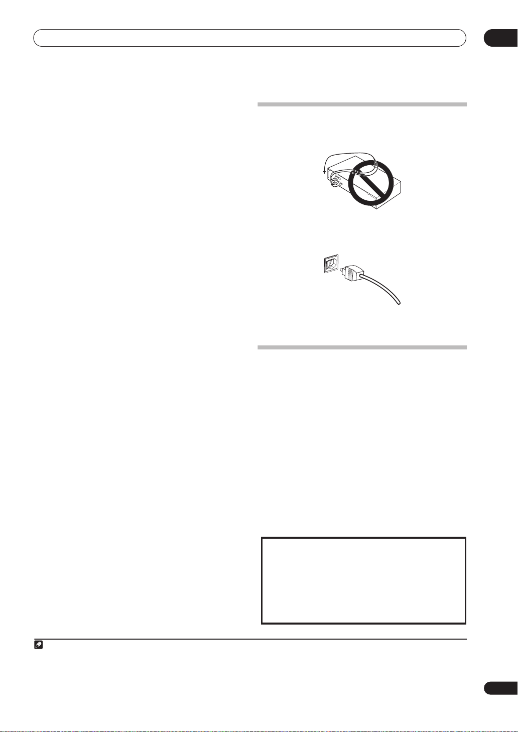
GROUNDING OR POLARIZATION
• If this product is equipped with a polarized
alternating current line plug (a plug having one
blade wider than the other), it will fit into the
outlet only one way. This is a safety feature. If
you are unable to insert the plug fully into the
outlet, try reversing the plug. If the plug should
still fail to fit, contact your electrician to replace
your obsolete outlet. Do not defeat the safety
purpose of the polarized plug.
• If this product is equipped with a three-wire
grounding type plug, a plug having a third
(grounding) pin, it will only fit into a grounding
type power outlet. This is a safety feature. If you
are unable to insert the plug into the outlet,
contact your electrician to replace your obsolete
outlet. Do not defeat the safety purpose of the
grounding type plug.
POWER-CORD PROTECTION — Power-supply
cords should be routed so that they are not likely
to be walked on or pinched by items placed
upon or against them, paying particular
attention to cords at plugs, convenience
receptacles, and the point where they exit from
the product.
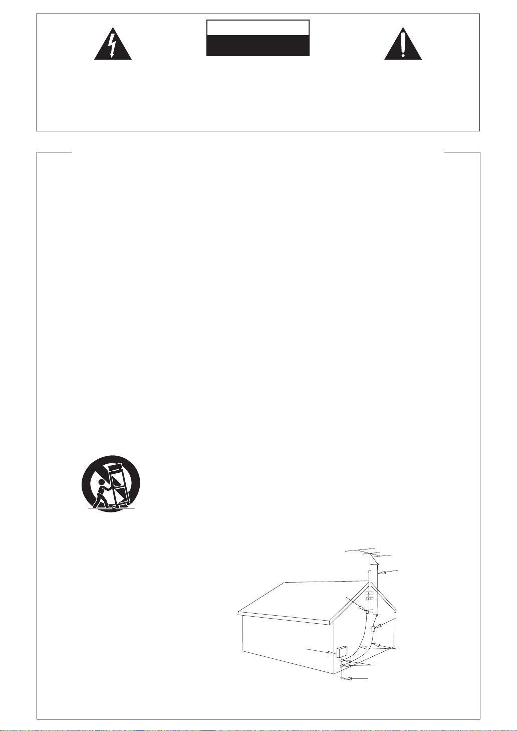
OUTDOOR ANTENNA GROUNDING — If an
outside antenna or cable system is connected to
the product, be sure the antenna or cable
system is grounded so as to provide some
protection against voltage surges and built-up
static charges. Article 810 of the National
Electrical Code, ANSI/NFPA 70, provides
information with regard to proper grounding of
the mast and supporting structure, grounding of
the lead-in wire to an antenna discharge unit,
size of grounding conductors, location of
antenna-discharge unit, connection to
grounding electrodes, and requirements for the
grounding electrode. See Figure A.
LIGHTNING — For added protection for this
product during a lightning storm, or when it is
left unattended and unused for long periods of
time, unplug it from the wall outlet and
disconnect the antenna or cable system. This
will prevent damage to the product due to
lightning and power-line surges.
POWER LINES — An outside antenna system
should not be located in the vicinity of overhead
power lines or other electric light or power
circuits, or where it can fall into such power
lines or circuits. When installing an outside
antenna system, extreme care should be taken
to keep from touching such power lines or
circuits as contact with them might be fatal.
OVERLOADING — Do not overload wall outlets,
extension cords, or integral convenience
receptacles as this can result in a risk of fire or
electric shock.
ELECTRIC
SERVICE
EQUIPMENT
Fig. A
OBJECT AND LIQUID ENTRY — Never push
objects of any kind into this product through
openings as they may touch dangerous voltage
points or short-out parts that could result in a
fire or electric shock. Never spill liquid of any
kind on the product.
SERVICING — Do not attempt to service this
product yourself as opening or removing covers
may expose you to dangerous voltage or other
hazards. Refer all servicing to qualified service
personnel.
DAMAGE REQUIRING SERVICE — Unplug this
product from the wall outlet and refer servicing
to qualified service personnel under the
following conditions:
• When the power-supply cord or plug is
damaged.
• If liquid has been spilled, or objects have fallen
into the product.
• If the product has been exposed to rain or water.
• If the product does not operate normally by
following the operating instructions. Adjust only
those controls that are covered by the operating
instructions as an improper adjustment of other
controls may result in damage and will often
require extensive work by a qualified technician
to restore the product to its normal operation.
• If the product has been dropped or damaged in
any way.
• When the product exhibits a distinct change in
performance — this indicates a need for service.
REPLACEMENT PARTS — When replacement parts
are required, be sure the service technician has
used replacement parts specified by the
manufacturer or have the same characteristics
as the original part. Unauthorized substitutions
may result in fire, electric shock, or other
hazards.
SAFETY CHECK — Upon completion of any service
or repairs to this product, ask the service
technician to perform safety checks to
determine that the product is in proper
operating condition.
WALL OR CEILING MOUNTING — The product
should not be mounted to a wall or ceiling.
HEAT — The product should be situated away from
heat sources such as radiators, heat registers,
stoves, or other products (including amplifiers)
that produce heat.
GROUND
CLAMP
GROUND CLAMPS
POWER SERVICE GROUNDING
ELECTRODE SYSTEM
(NEC ART 250, PART H)
NEC — NATIONAL ELECTRICAL CODE
D1-4-2-3_En
ANTENNA
LEAD IN
WIRE
ANTENNA
DISCHARGE UNIT
(NEC SECTION 810-20)
GROUNDING CONDUCTORS
(NEC SECTION 810-21)
D1-4-2-2_En

Thank you for buying this Pioneer product. Please read through these operating instructions so you will know how to operate
your model properly. After you have finished reading the instructions, put them away in a safe place for future reference.
Contents
01 Before you start
Checking what’s in the box. . . . . . . . . . . . . . . . . . . . . . . 6
Ventilation. . . . . . . . . . . . . . . . . . . . . . . . . . . . . . . . . . . . . 6
Installing the receiver . . . . . . . . . . . . . . . . . . . . . . . . . . . 6
Loading the batteries. . . . . . . . . . . . . . . . . . . . . . . . . . . . 6
02 5 minute guide
Introduction to home theater . . . . . . . . . . . . . . . . . . . . . 7
Listening to Surround Sound . . . . . . . . . . . . . . . . . . . . . 7
Automatically setting up for surround sound
(MCACC). . . . . . . . . . . . . . . . . . . . . . . . . . . . . . . . . . . . . . 7
Problems when using the Auto MCACC Setup . . . . . 9
Playing a source. . . . . . . . . . . . . . . . . . . . . . . . . . . . . . . . 9
Better sound using Phase Control. . . . . . . . . . . . . . . . . 9
03 Connecting your equipment
Rear panel . . . . . . . . . . . . . . . . . . . . . . . . . . . . . . . . . . . 10
When making cable connections. . . . . . . . . . . . . . . . . 11
About the video converter . . . . . . . . . . . . . . . . . . . . . . . 11
Connecting your TV and DVD player . . . . . . . . . . . . . . 12
Connecting a satellite/cable receiver or other
set-top box . . . . . . . . . . . . . . . . . . . . . . . . . . . . . . . . . . . 13
Connecting a DVD/HDD recorder, VCR and other
video sources . . . . . . . . . . . . . . . . . . . . . . . . . . . . . . . . . 13
Using the component video jacks . . . . . . . . . . . . . . . . 14
Connecting digital audio sources . . . . . . . . . . . . . . . . 15
About the WMA9 Pro decoder. . . . . . . . . . . . . . . . . . 15
Connecting analog audio sources . . . . . . . . . . . . . . . . 16
Connecting a component to the front panel inputs . . 16
Installing your speaker system . . . . . . . . . . . . . . . . . . .17
Connecting the speakers . . . . . . . . . . . . . . . . . . . . . . 17
Placing the speakers. . . . . . . . . . . . . . . . . . . . . . . . . . 18
THX speaker system setup . . . . . . . . . . . . . . . . . . . . . 19
Connecting antennas . . . . . . . . . . . . . . . . . . . . . . . . . . 19
AM loop antenna. . . . . . . . . . . . . . . . . . . . . . . . . . . . . 19
FM wire antenna . . . . . . . . . . . . . . . . . . . . . . . . . . . . . 20
Connecting external antennas. . . . . . . . . . . . . . . . . . 20
Plugging in the receiver . . . . . . . . . . . . . . . . . . . . . . . .20
AC outlet. . . . . . . . . . . . . . . . . . . . . . . . . . . . . . . . . . . . . 20
04 Controls and displays
Front panel . . . . . . . . . . . . . . . . . . . . . . . . . . . . . . . . . . . 21
Operating range of remote control unit . . . . . . . . . . 22
Display . . . . . . . . . . . . . . . . . . . . . . . . . . . . . . . . . . . . . . 23
Remote control. . . . . . . . . . . . . . . . . . . . . . . . . . . . . . . . 24
Sub remote control unit . . . . . . . . . . . . . . . . . . . . . . . . 26
05 Listening to your system
Auto playback . . . . . . . . . . . . . . . . . . . . . . . . . . . . . . . . 27
Listening in surround sound . . . . . . . . . . . . . . . . . . . . 27
Standard surround sound . . . . . . . . . . . . . . . . . . . . . 27
Using the Home THX modes. . . . . . . . . . . . . . . . . . . 28
Using the Advanced surround effects . . . . . . . . . . . 28
Listening in stereo. . . . . . . . . . . . . . . . . . . . . . . . . . . . . 29
Using Stream Direct . . . . . . . . . . . . . . . . . . . . . . . . . . . 29
Selecting MCACC presets . . . . . . . . . . . . . . . . . . . . . . 29
Choosing the input signal . . . . . . . . . . . . . . . . . . . . . . 30
Using surround back channel processing . . . . . . . . . 30
Using the Virtual Surround Back mode . . . . . . . . . . 30
Using the Sound Retriever . . . . . . . . . . . . . . . . . . . . . . 31
06 Using the tuner
Listening to the radio . . . . . . . . . . . . . . . . . . . . . . . . . . 32
Improving FM stereo sound. . . . . . . . . . . . . . . . . . . . 32
Tuning directly to a station . . . . . . . . . . . . . . . . . . . . 32
Saving station presets . . . . . . . . . . . . . . . . . . . . . . . . . 33
Naming station presets . . . . . . . . . . . . . . . . . . . . . . . 33
Listening to station presets . . . . . . . . . . . . . . . . . . . . 33
07 The System Setup menu
Making receiver settings from the System Setup
menu . . . . . . . . . . . . . . . . . . . . . . . . . . . . . . . . . . . . . . . 34
Automatic MCACC (Expert) . . . . . . . . . . . . . . . . . . . . . 34
Surround back speaker setting . . . . . . . . . . . . . . . . . . 36
Manual MCACC setup . . . . . . . . . . . . . . . . . . . . . . . . . 37
Fine Channel Level . . . . . . . . . . . . . . . . . . . . . . . . . . . 37
Fine Speaker Distance . . . . . . . . . . . . . . . . . . . . . . . . 38
Standing Wave . . . . . . . . . . . . . . . . . . . . . . . . . . . . . . 38
Acoustic Calibration EQ. . . . . . . . . . . . . . . . . . . . . . . 39
Professional Acoustic Calibration EQ . . . . . . . . . . . 39
Data Management . . . . . . . . . . . . . . . . . . . . . . . . . . . . 42
Manual speaker setup . . . . . . . . . . . . . . . . . . . . . . . . . 43
Speaker Setting . . . . . . . . . . . . . . . . . . . . . . . . . . . . . 43
Channel Level . . . . . . . . . . . . . . . . . . . . . . . . . . . . . . . 44
Speaker Distance . . . . . . . . . . . . . . . . . . . . . . . . . . . . 45
Bass Peak Level . . . . . . . . . . . . . . . . . . . . . . . . . . . . . 45
X-Curve . . . . . . . . . . . . . . . . . . . . . . . . . . . . . . . . . . . . 46
THX Audio Setting . . . . . . . . . . . . . . . . . . . . . . . . . . . 46
08 Other connections
Connecting an iPod . . . . . . . . . . . . . . . . . . . . . . . . . . . 47
Connecting your iPod to the receiver . . . . . . . . . . . . 47
iPod playback . . . . . . . . . . . . . . . . . . . . . . . . . . . . . . . 47
Watching photos and video content. . . . . . . . . . . . . 48
4
En

Using XM Radio . . . . . . . . . . . . . . . . . . . . . . . . . . . . . . . 48
Connecting your XM Radio receiver . . . . . . . . . . . . . 48
Listening to XM Radio. . . . . . . . . . . . . . . . . . . . . . . . . 49
Using XM HD Surround . . . . . . . . . . . . . . . . . . . . . . . 49
Saving channel presets . . . . . . . . . . . . . . . . . . . . . . . 49
Using the XM Menu . . . . . . . . . . . . . . . . . . . . . . . . . . 50
Connecting using HDMI . . . . . . . . . . . . . . . . . . . . . . . . 50
About HDMI . . . . . . . . . . . . . . . . . . . . . . . . . . . . . . . . . . 51
Using the i.LINK interface. . . . . . . . . . . . . . . . . . . . . . . 51
Checking the i.LINK inputs . . . . . . . . . . . . . . . . . . . . 52
About i.LINK. . . . . . . . . . . . . . . . . . . . . . . . . . . . . . . . . . 52
About PQLS rate control . . . . . . . . . . . . . . . . . . . . . . 53
Creating an i.LINK network . . . . . . . . . . . . . . . . . . . . 53
Connecting the multichannel analog inputs . . . . . . . 54
Selecting the multichannel analog inputs . . . . . . . . 54
Using the USB interface . . . . . . . . . . . . . . . . . . . . . . . . 54
Second Zone speaker B setup . . . . . . . . . . . . . . . . . . . 55
Switching the speaker system . . . . . . . . . . . . . . . . . . 55
Bi-amping your front speakers . . . . . . . . . . . . . . . . . . . 56
Bi-wiring your speakers. . . . . . . . . . . . . . . . . . . . . . . . . 56
Connecting additional amplifiers. . . . . . . . . . . . . . . . . 57
Multi-room listening . . . . . . . . . . . . . . . . . . . . . . . . . . . 57
Making multi-room connections . . . . . . . . . . . . . . . . 57
Using the multi-room controls. . . . . . . . . . . . . . . . . . 59
Connecting an IR receiver . . . . . . . . . . . . . . . . . . . . . . 59
Switching components on and off using the
12 volt trigger . . . . . . . . . . . . . . . . . . . . . . . . . . . . . . . . . 60
Using this receiver with a Pioneer plasma display. . . 60
Using the SR+ mode with a Pioneer plasma
display. . . . . . . . . . . . . . . . . . . . . . . . . . . . . . . . . . . . . . . 61
Connecting a PC for Advanced MCACC output . . . . . 62
Advanced MCACC output using your PC . . . . . . . . . 62
09 Other Settings
The Input Setup menu. . . . . . . . . . . . . . . . . . . . . . . . . . 63
Input function default and possible settings . . . . . . 64
The Other Setup menu . . . . . . . . . . . . . . . . . . . . . . . . . 64
Multi-Room Setup . . . . . . . . . . . . . . . . . . . . . . . . . . . . 65
SR+ Setup for Pioneer plasma displays. . . . . . . . . . 65
OSD Adjustment . . . . . . . . . . . . . . . . . . . . . . . . . . . . . 65
10 Using other functions
Setting the AV options. . . . . . . . . . . . . . . . . . . . . . . . . . 66
Making an audio or a video recording . . . . . . . . . . . . . 67
Playing a different source when recording. . . . . . . . 67
Reducing the level of an analog signal . . . . . . . . . . . . 68
Watching video and audio sources independently . . 68
Using the sleep timer . . . . . . . . . . . . . . . . . . . . . . . . . . 68
Dimming the display . . . . . . . . . . . . . . . . . . . . . . . . . . . 68
Switching the speaker impedance. . . . . . . . . . . . . . . . 68
Checking your system settings. . . . . . . . . . . . . . . . . . . 69
Resetting the system. . . . . . . . . . . . . . . . . . . . . . . . . . . 69
Default system settings . . . . . . . . . . . . . . . . . . . . . . . 69
11 Controlling the rest of your system
Setting the remote to control other components . . . . 71
Selecting preset codes directly . . . . . . . . . . . . . . . . . . 71
Programming signals from other remote controls . . 71
Erasing one of the remote control button settings . . 72
Resetting the remote control presets . . . . . . . . . . . . . 72
Confirming preset codes . . . . . . . . . . . . . . . . . . . . . . . 72
Renaming input source names . . . . . . . . . . . . . . . . . . 73
Direct function . . . . . . . . . . . . . . . . . . . . . . . . . . . . . . . 73
Multi Operation and System Off . . . . . . . . . . . . . . . . . 73
Programming a multi-operation or a shutdown
sequence. . . . . . . . . . . . . . . . . . . . . . . . . . . . . . . . . . . 73
Using multi operations . . . . . . . . . . . . . . . . . . . . . . . 74
Using System off . . . . . . . . . . . . . . . . . . . . . . . . . . . . 74
Controls for TVs. . . . . . . . . . . . . . . . . . . . . . . . . . . . . . . 75
Controls for other components . . . . . . . . . . . . . . . . . . 75
Operating other Pioneer components with this
unit’s sensor . . . . . . . . . . . . . . . . . . . . . . . . . . . . . . . . . 76
12 Additional information
Troubleshooting . . . . . . . . . . . . . . . . . . . . . . . . . . . . . . 77
Power. . . . . . . . . . . . . . . . . . . . . . . . . . . . . . . . . . . . . . 77
No sound. . . . . . . . . . . . . . . . . . . . . . . . . . . . . . . . . . . 77
Other audio problems . . . . . . . . . . . . . . . . . . . . . . . . 78
Video . . . . . . . . . . . . . . . . . . . . . . . . . . . . . . . . . . . . . . 79
Settings . . . . . . . . . . . . . . . . . . . . . . . . . . . . . . . . . . . . 80
Display. . . . . . . . . . . . . . . . . . . . . . . . . . . . . . . . . . . . . 80
Remote control. . . . . . . . . . . . . . . . . . . . . . . . . . . . . . 81
i.LINK interface. . . . . . . . . . . . . . . . . . . . . . . . . . . . . . 81
i.LINK messages. . . . . . . . . . . . . . . . . . . . . . . . . . . . . 82
USB interface . . . . . . . . . . . . . . . . . . . . . . . . . . . . . . . 82
HDMI . . . . . . . . . . . . . . . . . . . . . . . . . . . . . . . . . . . . . . 82
iPod messages . . . . . . . . . . . . . . . . . . . . . . . . . . . . . . 83
XM radio messages . . . . . . . . . . . . . . . . . . . . . . . . . . 83
Surround sound formats . . . . . . . . . . . . . . . . . . . . . . . 84
Dolby . . . . . . . . . . . . . . . . . . . . . . . . . . . . . . . . . . . . . . 84
DTS . . . . . . . . . . . . . . . . . . . . . . . . . . . . . . . . . . . . . . . 84
Windows Media® Audio 9 Professional . . . . . . . . . 84
About THX . . . . . . . . . . . . . . . . . . . . . . . . . . . . . . . . . . . 85
Listening modes with different input signal
formats. . . . . . . . . . . . . . . . . . . . . . . . . . . . . . . . . . . . . . 86
Stream direct with different input signal formats . . . 88
Specifications . . . . . . . . . . . . . . . . . . . . . . . . . . . . . . . . 89
Cleaning the unit. . . . . . . . . . . . . . . . . . . . . . . . . . . . . . 89
Our philosophy . . . . . . . . . . . . . . . . . . . . . . . . . . . . . . . 90
Features. . . . . . . . . . . . . . . . . . . . . . . . . . . . . . . . . . . . 90
WARNING: Handling the cord on this product or
cords associated with accessories sold with the
product will expose you to chemicals listed on
proposition 65 known to the State of California and
other governmental entities to cause cancer and
birth defect or other reproductive harm.
Wash hands after handling
This product is for general household purposes. Any
failure due to use for other than household purposes
(such as long-term use for business purposes in a
restaurant or use in a car or ship) and which requires
repair will be charged for even during the warranty
period.
D36-P4_A_En
K041_En
5
En
01
S
Before you start
Chapter 1:
Before you start
Checking what’s in the box
Please check that you've received the following supplied
accessories:
• Setup microphone (cable: 16.4 ft.)
• Remote control unit
• Sub room remote control unit
• AA/IEC R6P dry cell batteries
82TXS)
x2
• AM loop antenna
• FM wire antenna
• iPod cable
• Warranty card
• These operating instructions
(VSX-84TXSi only)
(VSX-84TXSi)
x4 /
(VSX-
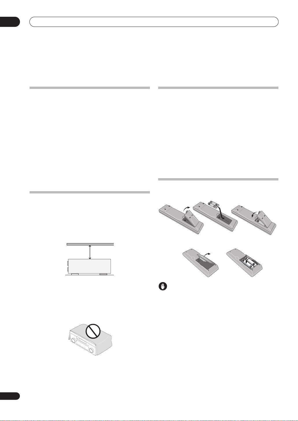
Ventilation
When installing this unit, make sure to leave space
around the unit for ventilation to improve heat dispersal
(at least 8 in. (20 cm) at the top). If not enough space is
provided between the unit and walls or other equipment,
heat will build up inside, interfering with performance
and/or causing malfunctions.
8 inches
Receiver
(20 cm)
Installing the
• When installing this unit, make sure to put it on a
level and stable surface.
Don’t install it on the following places:
– on a color TV (the screen may distort)
– near a cassette deck (or close to a device that gives off
a magnetic field). This may interfere with the sound.
– in direct sunlight
– in damp or wet areas
– in extremely hot or cold areas
– in places where there is vibration or other movement
– in places that are very dusty
– in places that have hot fumes or oils (such as a kitchen)
receiver
Loading the batteries
Main remote control unit:
ub room remote control unit (VSX-84TXSi Only):
Slot and openings in the cabinet are provided for
ventilation and to protect the equipment from
overheating. To prevent fire hazard, do not place anything
directly on top of the unit, make sure the openings are
never blocked or covered with items (such as
newspapers, table-cloths and curtains), and do not
operate the equipment on thick carpet or a bed.
6
En
Caution
Incorrect use of batteries may result in such hazards as
leakage and bursting. Observe the following precautions:
• Never use new and old batteries together.
• Insert the plus and minus sides of the batteries
properly according to the marks in the battery case.
• Batteries with the same shape may have different
voltages. Do not use different batteries together.
• When disposing of used batteries, please comply
with governmental regulations or environmental
public instruction’s rules that apply in your country or
area.
5 minute guide
Chapter 2:
5 minute guide
Introduction to home theater
Home theater refers to the use of multiple audio tracks to
create a surround sound effect, making you feel like
you're in the middle of the action or concert. The
surround sound you get from a home theater system
depends not only on your speaker setup, but also on the
source and the sound settings of the receiver.
This receiver will automatically decode multichannel
Dolby Digital, DTS, or Dolby Surround sources according
to your speaker setup. In most cases, you won’t have to
make changes for realistic surround sound, but other
possibilities (like listening to a CD with multichannel
surround sound) are explained in
system
on page 27.
Listening to Surround Sound
This receiver was designed with the easiest possible
setup in mind, so with the following quick setup guide,
you should have your system hooked up for surround
sound in no time at all. In most cases, you can simply
leave the receiver in the default settings.
• Be sure to complete all connections before
connecting this unit to an AC power source.
1 Connect your TV and DVD player.
See
Connecting your TV and DVD player
this. For surround sound, you’ll want to hook up using a
digital connection from the DVD player to the receiver.
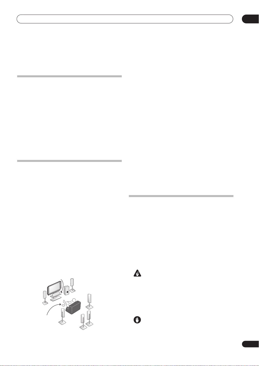
2 Connect your speakers and place them for optimal
surround sound.
Connect your speakers as shown in
speaker system
Where you place the speakers will have a big effect on the
sound. Place your speakers as shown below for the best
surround sound effect. Also see
page 18 for more on this.
Front
Left (L)
on page 17.
Center (C)
Listening
position
Surround
Left (SL)
Subwoofer (SW)
Listening to your
on page 12 to do
Installing your
Placing the speakers
Front
Right (R)
Surround
Right (SR)
Surround
Back
Right (SBR)
Surround
Back Left (SBL)
on
02
3 Plug in the receiver and switch it on, followed by
your DVD player, your subwoofer and the TV.
Make sure you’ve set the video input on your TV to this
receiver. Check the manual that came with the TV if you
don’t know how to do this.
• Set the subwoofer volume to a comfortable level.
4 Use the on-screen automatic MCACC setup to set up
your system.
See
Automatically setting up for surround sound
(MCACC)
below for more on this.
5 Play a DVD, and adjust the volume to your liking.
Make sure that
DVD/LD
is showing in the receiver’s
display, indicating that the DVD input is selected. If it
isn’t, press
DVD/LD
on the remote control to set the
receiver to the DVD input.
In addition to the basic playback explained in
source
on page 9, there are several other sound options
you can select. See
Listening to your system
Playing a
on page 27
for more on this.
See also
menu
Making receiver settings from the System Setup
on page 34 for more setup options.
Automatically setting up for surround
sound (MCACC)
The Auto MCACC Setup measures the acoustic
characteristics of your listening area, taking into account
ambient noise, speaker size and distance, and tests for
both channel delay and channel level. After you have set
up the microphone provided with your system, the
receiver uses the information from a series of test tones
to optimize the speaker settings and equalization for your
particular room.
Make sure you do this before moving on to
source
on page 9.
Important
• Make sure the microphone and speakers are not
moved during the Auto MCACC Setup.
• Using the Auto MCACC Setup will overwrite any
existing settings for the MCACC preset you select.
• Before using the Auto MCACC Setup the
headphones should be disconnected.
Caution
• The test tones used in the Auto MCACC Setup are
output at high volume.
Playing a
En
7
02
5 minute guide
RECEIVER SOURCE
SELECT
CD
TV VIDEO 2
DVD SAT
VIDEO 1 TV CONT
DVR2
CD-R
XM RADIO
TUNER
ROOM2/3
RECEIVER
DVR1 i Pod
D.ACCESS
AV PARAMETER
TOP MENU
DTV MENU
SETUPSETUP
CATEGORY
GUIDE
TV VOL
+
ST ST
10
TUNE
TUNE
TV CONTROL
INPUT
SELECT
ENTER
TV CH
BAND
CLASS
ENTER
CH LEVEL
MENU
T.EDIT
RETURNRETURN
VOL
DISC
SYSTEM OFF
INPUT
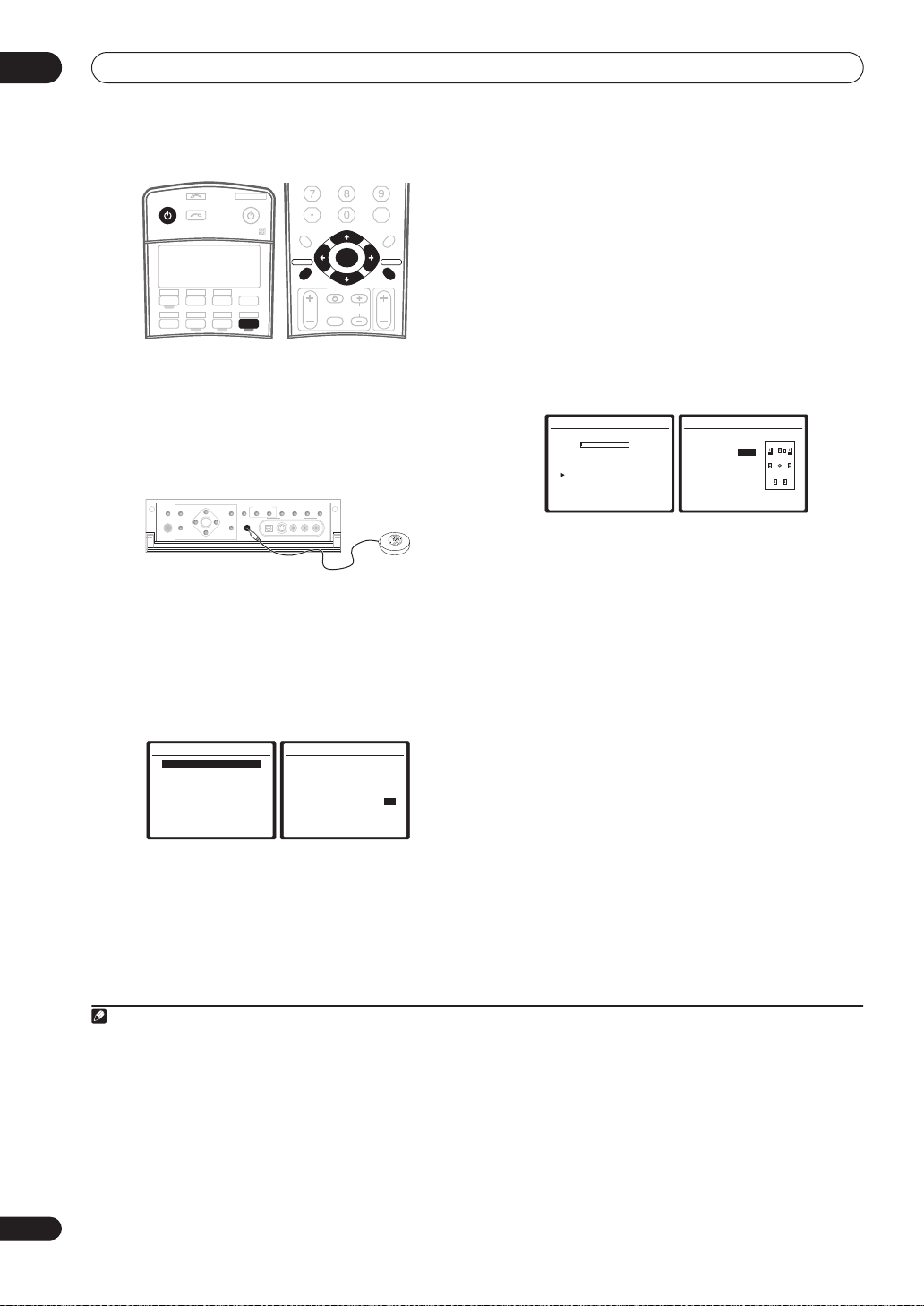
1 Switch on the receiver and your TV.
2 Connect the microphone to the MCACC
SETUP MIC
jack on the front panel.
Place the microphone so that it’s about ear level at your
normal listening position (use a tripod if possible). Make
sure there are no obstacles between the speakers and
the microphone.
MULTI – ROOM &
3 Press
(TUNE +)
SPEAKERS
AV
PARAMETER
PHONES
(ST –) (ST +)
ENTER
SETUP
(TUNE –)
RECEIVER
TUNER
EDIT
RETURN
on the remote, then press
BAND
CONTROL ON/OFF
MCACC
SETUP MIC
VIDEO
SOURCE/REC SEL
SELECT
VIDEO/GAME 2 INPUT
DIGITAL IN S-VIDEO VIDEO L RAUDIO
SIGNAL
SBch
STEREO
SELECT
PROCESSING
1
SETUP
.
An on-screen display (OSD) appears on your TV. Use the
///
screens and select menu items. Press
the current menu. Press
buttons and
ENTER
to navigate through the
RETURN
SETUP
at any time to cancel.
to exit
2
4 Select ‘Auto MCACC’ from the System Setup menu
then press
5 Make sure ‘Normal (SB)’ is selected,
MCACC preset
ENTER
System Setup
1.Auto MCACC
2.Surr Back System
3.Manual MCACC
4.Data Management
5.Manual SP Setup
6.Input Setup
7.Other Setup
4
then select OK.
.
: Exit
1.Auto MCACC
Surr Back System
[ Normal (SB) ]
Data Save to
[M1. MEMORY 1 ]
Setting Start? [OK]
[Option]
ENTER:Next :Cancel
3
select an
6 Follow the instructions on-screen.
Make sure the microphone is connected, and if you’re
using a subwoofer, make sure it is switched on and set to
a comfortable volume level.
7 Wait for the test tones to finish then confirm the
speaker configuration in the OSD.
A progress report is displayed on-screen while the
receiver outputs test tones to determine the speakers
present in your setup. Try to be as quiet as possible while
it’s doing this.
• With error messages (such as
Microphone Check
ambient noise (see
MCACC Setup
5
Ambient Noise
) select
RETRY
Problems when using the Auto
below) and verifying the mic
or
after checking for
connection. If there doesn’t seem to be a problem,
you can simply select
1.Auto MCACC
Now Analyzing… (2/9)
Environment Check
Ambient Noise [ OK ]
Microphone [ ]
Speaker YES/NO [ ]
:Cancel
OK
and continue.
1.Auto MCACC
Check!
Front [ YES ]
Center [ YES ]
Surround [ YES ]
SB [ Yx2 ]
SUB W. [ YES ]
[ OK ]
:Cancel
The configuration shown on-screen should reflect the
actual speakers you have.
If you see an error message (
6
ERR
) in the right side
column (or the speaker configuration displayed isn’t
correct), there may be a problem with the speaker
connection. If selecting
RETRY
doesn’t work, turn off the
power and check the speaker connections. If there
doesn’t seem to be a problem, you can simply use
to select the speaker and
/
to change the setting
/
(and number for surround back) and continue.
8 Make sure ‘OK’ is selected, then press
ENTER
.
A progress report is displayed on-screen while the
receiver outputs more test tones to determine the
optimum receiver settings for channel level, speaker
distance, and Acoustic Calibration EQ.
Again, try to be as quiet as possible while this is
happening. It may take 2 to 6 minutes.
9 The Auto MCACC Setup has finished! Press
to go back to the System Setup menu.
RETURN
7
The settings made in the Auto MCACC Setup should give
you excellent surround sound from your system, but it is
also possible to adjust these settings manually using the
System Setup menu (starting on page 34).
8
8
En
Note
1 You can’t use the System Setup menu when the iPod or XM Radio input source is selected (in either the main or sub room).
2 If you cancel the Auto MCACC Setup, or leave an error message for over three minutes, the screen saver will appear.
3• If you are planning on bi-amping your front speakers, or setting up a separate speaker system in another room, read through
setting
on page 36 and make sure to connect your speakers as necessary before continuing to step 6.
• If you have THX-certified speakers, select
4 The six MCACC presets are used for storing surround sound settings for different listening positions. Simply choose an unused preset for now (you can
rename it later in
5 Do not adjust the volume during the test tones. This may result in incorrect speaker settings.
6 If you’re using the front panel display, the diagram in
7 You can also choose to view the settings from the
8• Depending on the characteristics of your room, sometimes identical speakers with cone sizes of around 5 inches (12 cm) will end up with different
size settings. You can correct the setting manually using the
• The subwoofer distance setting may be farther than the actual distance from the listening position. This setting should be accurate (taking delay and
room characteristics into account) and generally does not need to be changed.
Data Management
Option
on page 42).
and choose
MCACC Data Check
YES
for the
Listening to Surround Sound
screen. See
Manual speaker setup
THX Speaker
setting.
above indicates (in bold) how each speaker is displayed.
Automatic MCACC (Expert)
on page 34 for more on this.
on page 43.
Surround back speaker
5 minute guide
GUIDE
02
Problems when using the Auto MCACC Setup
If the room environment is not optimal for the Auto
MCACC Setup (too much background noise, echo off the
4 Use the volume control to adjust the volume level.
Turn down the volume of your TV so that all sound is
coming from the speakers connected to this receiver.
walls, obstacles blocking the speakers from the
microphone) the final settings may be incorrect. Check
for household appliances (air conditioner, fridge, fan,
etc.), that may be affecting the environment and switch
them off if necessary. If there are any instructions
showing in the front panel display, please follow them.
• Some older TVs may interfere with the operation of
the microphone. If this seems to be happening,
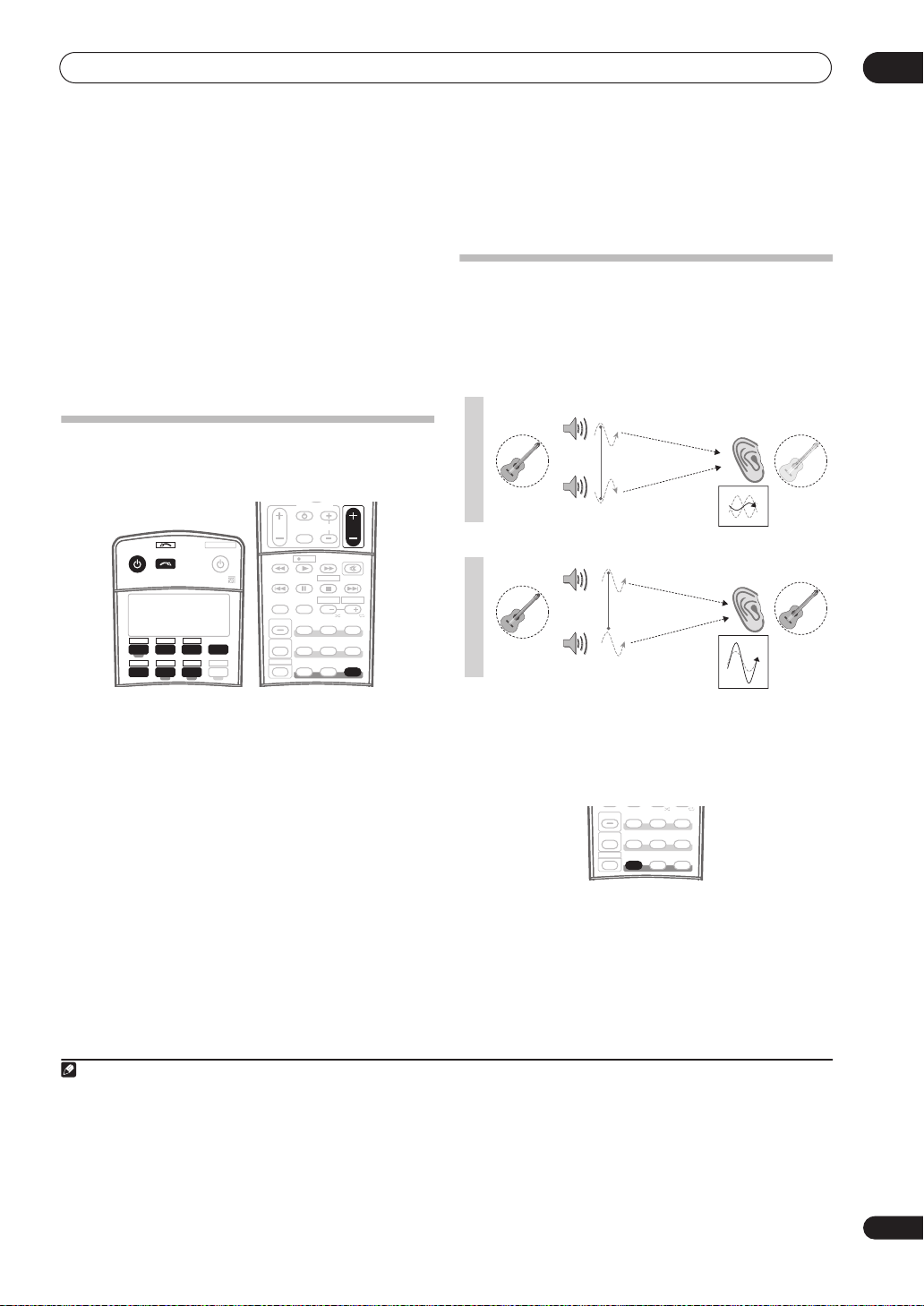
Better sound using Phase Control
This receiver’s Phase Control feature uses phase
correction measures to make sure your sound source
arrives at the listening position in phase, preventing
unwanted distortion and/or coloring of the sound (see
illustration below).
switch off the TV when doing the Auto MCACC Setup.
Playing a source
Here are the basic instructions for playing a source (such
as a DVD disc) with your home theater system.
TV CONTROL
INPUT
TV CH
SYSTEM OFF
INPUT
RECEIVER SOURCE
SELECT
TV VIDEO 2
CD
DVD SAT
VIDEO 1 TV CONT
DVR2
CD-R
XM RADIO
TUNER
ROOM2/3
RECEIVER
DVR1 i Pod
TV VOL
MPX
AUDIO SUBTITLE
DISP
STATUS
SIGNAL SEL
MULTI OPE
SHIFT
SELECT
THX
PHASE
REC
PHOTO
DTV INFO
REC STOP
MEMORY
HDD
CH
SBch
ADV. SURR
STANDARD
MCACC S.DIRECT
MUTE
STEREO
VOL
DVD
CH
P
H
A
S
E
C
O
N
T
O
Sound
F
F
source
P
H
A
S
E
C
O
N
T
Sound
O
N
source
Front speaker
Subwoofer
Front speaker
Subwoofer
Listening
position
Listening
position
?
1 Switch on your system components and receiver.
Start by switching on the playback component (for
example a DVD player), your TV
have one), then the receiver (press
1
and subwoofer (if you
RECEIVER
).
• Make sure the setup mic is disconnected.
2 Select the input source you want to play.
You can use the input source buttons on the remote
control,
SELECTOR
3 Press
SURROUND’ and start playback of the source.
INPUT SELECT
dial.
, or the front panel
2
S. DIRECT (STREAM DIRECT
INPUT
) to select ‘AUTO
3
If you’re playing a Dolby Digital or DTS surround sound
Phase Control technology provides coherent sound
reproduction through the use of phase matching
optimal sound image at your listening position. The
default setting is on and we recommend leaving Phase
Control switched on for all sound sources.
PHOTO
STATUS
SBch
STEREO
SIGNAL SEL
ADV. SURR
STANDARD
THX
MULTI OPE
SHIFT
MCACC S.DIRECT
PHASE
• Press PHASE (
PHASE CONTROL
) to switch on phase
correction.
The
PHASE CONTROL
indicator on the front panel lights.
DVD disc, you should hear surround sound. If you are
playing a stereo source, you will only hear sound from the
front left/right speakers in the default listening mode.
• See also
Listening to your system
on page 27 for
information on different ways of listening to sources.
Note
1 Make sure that the TV’s video input is set to this receiver. (For example, if you connected this receiver to the
the
VIDEO 1
2 If you need to manually switch the input signal type press
3• You may need to check the digital audio output settings on your DVD player or digital satellite receiver. It should be set to output Dolby Digital, DTS
and 88.2 kHz / 96 kHz PCM (2 channel) audio, and if there is an MPEG audio option, set this to convert the MPEG audio to PCM.
a multichannel listening mode (see
4 Phase matching is a very important factor in achieving proper sound reproduction. If two waveforms are 'in phase', they crest and trough together, resulting in increased amplitude, clarity and presence of the sound signal. If a crest of a wave meets a trough (as shown in the upper section of the diagram
above) then the sound will be 'out of phase' and an unreliable sound image will be produced.
input is now selected.)
• Depending on your DVD player or source discs, you may only get digital 2 channel stereo and analog sound. In this case, the receiver must be set to
Listening in surround sound
SIGNAL SEL
(page 30).
on page 27 if you need to do this) if you want multichannel surround sound.
VIDEO 1
jacks on your TV, make sure that
4
for an
9
En

03
Connecting your equipment
Chapter 3
Connecting your equipment
This receiver provides you with many connection possibilities, but it doesn’t have to be difficult. This page explains the
kinds of components you can connect to make up your home theater system.
Rear panel
This illustration shows the VSX-84TXSi, however connections for the 82TXS are the same except where noted.
MULTI-ROOM
& SOURCE
/
REC SEL
1
OUT1
ROOM3
(
)
ZONE3
OUT2
USB
AUDIO
2
IN
1
IN
3
(
)
SAT
2
IN
(
DVR/
VCR 1
3
IN
(
DVR/
VCR 2
4
IN
(
CD-R
ASSIGNA-
BLE
1
IN
(
DVD/
)
LD
2
IN
(CD)
IN
4
XM
IR
7
5
6
)
)
)
1
DIGITAL
MAIN ROOM(ZONE1
S400
IN1
(
)
AUDIO
ROOM2(ZONE2
IN2
S400
HDMI
IN1
8
1
(
DC OUT 12V TOTAL 50 mA MAX
ROOM2
9
(
)
ZONE2
IN2
1
IN
Y
10
IN3
B
P
4
PR
21
IN4
2
IN
Y
B
P
OUT
PR
ASSIGNABLE
COMPONENT VIDEO
MULTI-ROOM
& SOURCE
)
12 V TRIGGER
MULTI-ROOM
& SOURCE
)
MONITOR
OUT
OUT
OUT
IN
11
12
2
13
)
IN
Y
IN
B
P
PR
3
Y
B
P
PR
31
FM UNBAL 75 Ω
MONITOR
OUT
(
1
DVD/LD
(TV)
2
21
ASSIGNABLE
S - VIDEO
VIDEO
IN
IN
1
2
)
VIDEO
VIDEO /
GAME1
ANTENNA
AM LOOP
MULTI-ROOM & SOURCE
ROOM2(ZONE2
R
9
OUT
DVD/
LD
IN
TV
IN
SAT
IN
IN
OUT
DVR/
VCR 1
IN
OUT
DVR/
VCR 2
IN
R L
AUDIO
AUDIO PRE OUT
PHONO
14
IN
)
L
CD
IN
OUT
CD-R/
TAPE
IN
R
FR FL
15
SUB W.
SURROUND
R
R
16
OUT
CONTROL
Caution
• Before making or changing the connections, switch
off the power and disconnect the power cord from the
power outlet. Plugging in should be the final step.
1 Optical digital audio output(s)
Use the
OUT1
and
(VSX-84TXSi only) OUT2
jack for
recording to a CD or MiniDisc recorder.
Connecting digital audio sources
The
OUT1
jack is also used for multi-room connections.
Multi-room listening
2 USB audio input
on page 57.
(VSX-84TXSi only)
on page 15.
Use to connect your PC as an audio source.
Using the USB interface
on page 54.
3 Optical and coaxial digital audio inputs (x6)
Use for digital audio sources, including DVD players/
recorders, digital satellite receivers, CD players, etc.
See also
The Input Setup menu
on page 63 to assign
the inputs.
4 XM Radio input
See
Using XM Radio
5 S-400 i.LINK connectors (x2)
on page 48.
(VSX-84TXSi only)
Use to connect other i.LINK audio devices for highresolution, multichannel digital audio input/output.
Using the i.LINK interface
on page 51.
SURROUND
BACK
MULTI CH
IN
LR
FRONT
17
CENTER
SUB W.
SUR-
CENTER
ROUND
SURROUND
BACK
(
)
Single
LAR
L
iPod
SPEAKERS
18
IN
FRONT
RL R LRL
20
CENTER
SURROUND
21
SWITCHED 100 W(0.8A) MAX
SURROUND BACK /
(
Single
19
L
L
RS-232C
IN
6 HDMI connectors (x4)
(VSX-82TXS)
Multiple inputs and one output for high-quality audio/
video connection to compatible HDMI devices.
Connecting using HDMI
on page 50.
7 Remote inputs (multi-room and source)
Use for connection to an external remote control sensor
for use in a multi-room setup, for example.
Connecting an IR receiver
8 12V trigger jacks
on page 59.
(total 50 mA max.)
Use to switch components in your system on and off
according to the input function of the receiver.
Switching components on and off using the 12 volt
trigger
on page 60.
9 Multi-room and source outputs
Use to connect a second amplifier in a separate room.
Multi-room listening
on page 57.
10 Component video connections (x4)
Use the inputs to connect any video source that has
component video output, such as a DVD recorder. Use
the output for connection to a monitor or TV.
Using the component video jacks
11 AM and FM antenna terminals
Use to connect indoor or outdoor antennas for radio
broadcasts.
Connecting antennas
on page 19.
SELECTABLE
(x5)
(VSX-84TXSi)
(x2)
on page 14.
AC OUTLET
B
)
10
En
Connecting your equipment
12 Composite and S-video monitor outputs
Use to connect monitors and TVs.
Connecting your TV and DVD player
13 Audio/video source inputs/(outputs) (x6)
Use for connection to audio/visual sources, such as DVD
players/recorders, VCRs, etc. Each set of inputs has jacks
for composite video, S-video
Connecting a DVD/HDD recorder, VCR and other video
sources
on page 13.
1
and stereo analog audio.
14 Stereo analog audio source inputs/(outputs) (x3)
Use for connection to audio sources such as CD players,
tape decks, turntables, etc.
Connecting analog audio sources
15 Multichannel analog audio inputs
7.1 channel inputs for connection to a DVD player with
multichannel analog outputs.
Connecting the multichannel analog inputs
page 54.
16 Control input/output
Use to connect other Pioneer components so that you
can control all your equipment from a single IR remote
sensor.
Operating other Pioneer components with this unit’s
sensor
on page 76.
17 Multichannel pre-amplifier outputs
Use to connect separate amplifiers for center, surround,
surround back and subwoofer channels.
Connecting additional amplifiers
Installing your speaker system
on page 17 for powered
subwoofer connection).
18 iPod input terminal
Use to connect your Apple iPod as an audio or video
source.
Connecting an iPod
on page 47.
19 RS-232C connector
Use for connection to a PC for graphical output when
using Advanced MCACC.
Connecting a PC for Advanced MCACC output
page 62.
20 Speaker terminals
Use for connection to the main front, center, surround
and surround back speakers.
Installing your speaker system
21 Switched AC power outlet
Use to power another component in the system. Power to
the outlet switches on and off with the receiver.
AC outlet
on page 20.
on page 12.
on page 16.
on
on page 57 (see also
on
on page 17.
(100 W / 0.8 A max.)
When making cable connections
• To avoid hum, do not lay connected cables over the
top of the receiver.
• When connecting optical cables, be careful when
inserting the plug not to damage the shutter
protecting the optical socket.
• When storing optical cable, coil loosely. The cable
may be damaged if bent around sharp corners.
About the video converter
The video converter ensures that all video sources are
output through all of the
The only exception is HDMI and high-definition
component video: since these resolutions cannot be
downsampled, you must connect your monitor/TV to the
receiver’s HDMI/component video outputs when
connecting these video sources.
If several video components are assigned to the same
input function (see
the converter gives priority to HDMI, component, S-video,
then composite (in that order).
• For optimal video performance, THX recommends
switching Digital Video Conversion (in
options
on page 66)
This product incorporates copyright protection technology
that is protected by U.S. patents and other intellectual
property rights. Use of this copyright protection
technology must be authorized by Macrovision
Corporation, and is intended for home and other limited
consumer uses only unless otherwise authorized by
Macrovision. Reverse engineering or disassembly is
prohibited.
MONITOR VIDEO OUT
2
The Input Setup menu
OFF
.
jacks.
on page 63),
Setting the AV
03
Note
1 You must assign the input source to the S-video input to which you’ve connected your video component (see
2 If the video signal does not appear on your TV or plasma display, try adjusting the resolution settings on your component or display. Note that some
components (such as video game units) have resolutions that may not be converted. In this case, try switching Digital Video Conversion (in
options
on page 66)
OFF
.
The Input Setup menu
on page 63).
Setting the AV
11
En
03
F
R
Connecting your equipment
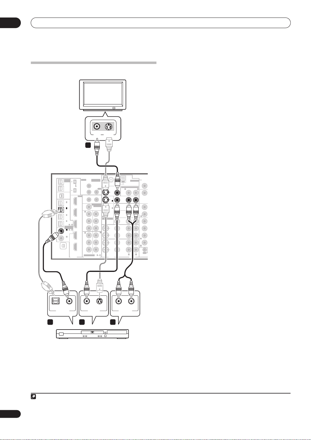
Connecting your TV and DVD player
TV
VIDEOINS-VIDEO
IN
1
MULTI-ROOM
& SOURCE
/
REC SEL
OUT1
ROOM3
(
ZONE3
OUT2
USB
AUDIO
IN
IN
(
SAT
IN
(
DVR/
VCR 1
IN
(
DVR/
VCR 2
IN
(
CD-R
ASSIGNABLE
IN
(
LD
IN
(CD)
XM
VSX-84TXSi
IR
MULTI-ROOM
& SOURCE
)
MAIN ROOM(ZONE1
S400
)
IN1
(
)
AUDIO
ROOM2(ZONE2
IN2
S400
HDMI
IN1
1
2
3
4
1
DVD/
)
2
IN
1
(
DC OUT 12V TOTAL 50 mA MAX
)
ROOM2
(
ZONE2
IN2
)
1
IN
Y
)
IN3
P
B
)
41
PR
21
IN4
2
IN
Y
B
P
OUT
PR
ASSIGNABLE
COMPONENT VIDEO
DIGITAL
12 V TRIGGER
)
)
MULTI-ROOM
& SOURCE
MONITOR
OUT
OUT
2
OUT
Y
P
B
PR
3
IN
Y
B
P
PR
31
FM UNBAL 75 Ω
)
1
IN
2
IN
21
ASSIGNABLE
S - VIDEO
MULTI-ROOM & SOURCE
MONITOR
OUT
OUT
DVD/
LD
1
IN
IN
TV
IN
2
IN
(
)
DVD/LD
SAT
(TV)
IN
VIDEO /
GAME1
IN
OUT
DVR/
VCR 1
IN
OUT
DVR/
VCR 2
IN
VIDEO
VIDEO
AM LOOP
ROOM2(ZONE2
R
ANTENNA
R L
AUDIO
AUDIO
PHONO
IN
)
L
CD
IN
OUT
CD-R/
TAPE
IN
R
FR
SUB W.
SURROUND
R
R
SUR
OUT
CONTROL
component video jacks
on page 14 if your TV and/or DVD
player has component video inputs/outputs. If your DVD
player offers multichannel analog audio outputs, see
Connecting the multichannel analog inputs
on page 54.
1 Connect the MONITOR OUT video jack to a video
input on your TV.
Use a standard RCA/phono jack video cable to connect to
the composite video jack, or for higher quality video, use
an S-video cable to connect to the S-video jack.
2 Connect a composite or S-video output on your DVD
player to the
DVD/LD
VIDEO or
DVD/LD
S-VIDEO input.
Connect using a standard video cable or an S-video
cable.
3 Connect a coaxial-type1 digital audio output on
your DVD player to the DIGITAL 1 (
DVD/LD
) input.
Use a coaxial cable designed for digital audio.
4 Connect the stereo audio outputs on your DVD
player to the
DVD/LD
AUDIO inputs.
Connect using a stereo RCA/phono jack cable.
• If your DVD player has multichannel analog outputs,
you can connect these instead. See also
the multichannel analog inputs
on page 54.
Connecting
12
En
COAXIAL
DIGITAL OUT VIDEO OUT
3
S-VIDEOOPTICAL
2 4
AUDIORL
ANALOG OUT
DVD player
The diagram shows a basic setup of this receiver together
with a TV and DVD player, with S-video or composite
video connections. Different TVs and DVD players may
offer alternative connections. See also
Note
1 If your DVD player only has an optical digital output, you can connect it to one of the optical inputs on this receiver using an optical cable. When you set
up the receiver you’ll need to tell the receiver which input you connected the player to (see
Using the
The Input Setup menu
on page 63).
Connecting your equipment
F
R
R
L
03
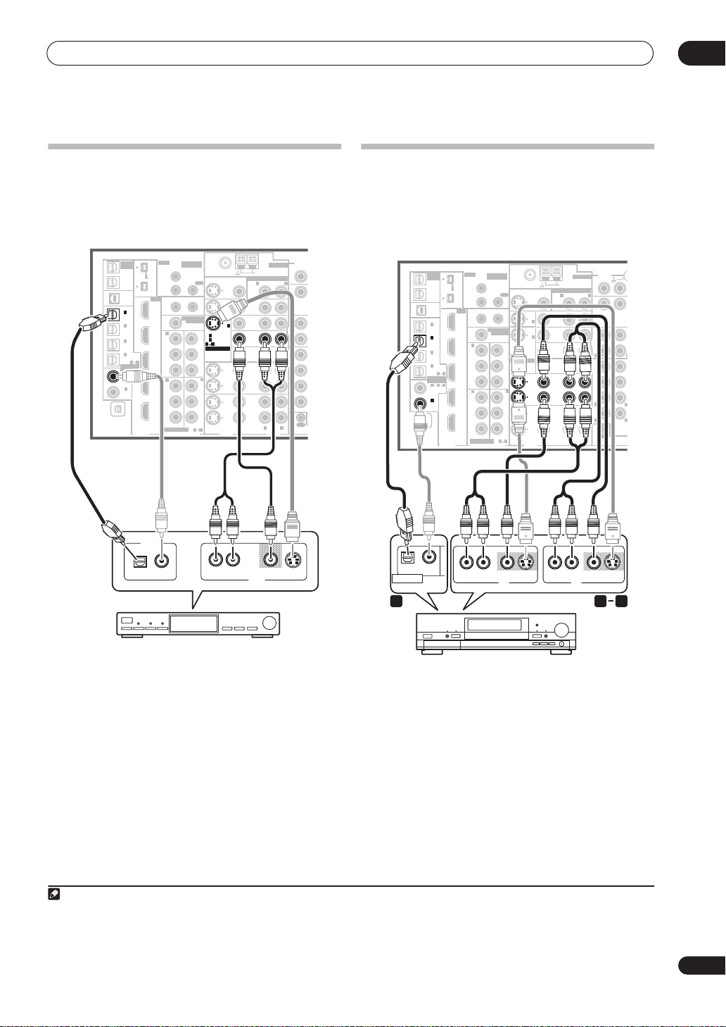
Connecting a satellite/cable
receiver
or other set-top box
Satellite and cable receivers, and terrestrial digital TV
tuners are all examples of so-called ‘set-top boxes’.
VSX-84TXSi
MULTI-ROOM
IR
XM
& SOURCE
/
REC SEL
OUT1
ROOM3
(
ZONE3
OUT2
USB
AUDIO
IN
IN
(
SAT
IN
(
DVR/
VCR 1
IN
(
DVR/
VCR 2
IN
(
CD-R
ASSIGNABLE
IN
(
DVD/
LD
IN
(CD)
MULTI-ROOM
& SOURCE
)
MAIN ROOM(ZONE1
ROOM2(ZONE2
12 V TRIGGER
1
)
)
MULTI-ROOM
& SOURCE
MONITOR
OUT
FM UNBAL 75 Ω
MULTI-ROOM & SOURCE
MONITOR
OUT
OUT
2
)
OUT
IN
Y
IN
P
B
P
R
3
IN
Y
P
B
P
R
31
(
1
DVD/LD
(TV)
2
21
ASSIGNABLE
S - VIDEO
OUT
DVD/
LD
1
IN
IN
TV
IN
2
IN
)
SAT
IN
VIDEO /
GAME1
IN
OUT
DVR/
VCR 1
IN
OUT
DVR/
VCR 2
IN
VIDEO
VIDEO
AV OUT
S400
)
IN1
(
)
AUDIO
IN2
S400
HDMI
IN1
1
(
DC OUT 12V TOTAL 50 mA MAX
)
ROOM2
2
(
ZONE2
IN2
)
1
IN
Y
3
)
IN3
4
P
B
)
4
1
P
R
1
21
IN4
2
IN
)
Y
2
P
B
OUT
IN
P
R
ASSIGNABLE
COMPONENT VIDEO
DIGITAL
DIGITAL OUT
ANTENNA
AM LOOP
ROOM2(ZONE2
R L
R L
AUDIO
VIDEO S-VIDEOAUDIORL
AUDIO
PHONO
IN
)
CD
IN
OUT
CD-R/
TAPE
IN
R
FR
SUB W.
SURROUND
R
R
SUR
OUT
CONTROL
Connecting a DVD/HDD recorder, VCR
and other video sources
This receiver has two sets of audio/video inputs and
outputs suitable for connecting analog or digital video
devices, including DVD/HDD recorders and VCRs.
VSX-84TXSi
MULTI-ROOM
IR
OPTICAL COAXIAL
DIGITAL OUT
& SOURCE
/
REC SEL
OUT1
S400
ROOM3
(
)
ZONE3
OUT2
S400
USB
AUDIO
IN
1
IN
(
)
SAT
2
IN
(
DVR/
)
VCR 1
3
IN
(
DVR/
)
VCR 2
4
IN
(
)
CD-R
41
ASSIGNABLE
1
21
IN
(
DVD/
)
LD
2
IN
(CD)
IN
XM
DIGITAL
MULTI-ROOM
& SOURCE
)
MAIN ROOM(ZONE1
ROOM2(ZONE2
12 V TRIGGER
1
)
B
B
)
MULTI-ROOM
& SOURCE
MONITOR
OUT
OUT
2
)
OUT
IN
Y
IN
ASSIGNABLE
B
P
PR
3
IN
Y
B
P
PR
S - VIDEO
31
VIDEOAUDIORL
AV OUT
FM UNBAL 75 Ω
MULTI-ROOM & SOURCE
MONITOR
OUT
OUT
DVD/
LD
1
IN
IN
TV
IN
2
IN
(
)
1
DVD/LD
SAT
(TV)
2
IN
21
VIDEO /
GAME1
IN
OUT
DVR/
VCR 1
IN
OUT
DVR/
VCR 2
IN
VIDEO
VIDEO
S-VIDEO AUDIORL
IN1
(
)
AUDIO
IN2
HDMI
IN1
(
DC OUT 12V TOTAL 50 mA MAX
ROOM2
(
ZONE2
IN2
1
IN
Y
IN3
P
PR
IN4
2
IN
Y
P
OUT
PR
ASSIGNABLE
COMPONENT VIDEO
AM LOOP
ROOM2(ZONE2
R
ANTENNA
R L
AUDIO
AV IN
PHONO
IN
)
L
CD
IN
OUT
CD-R/
TAPE
IN
R
FR FL
SUB W.
SUR-
ROUND
R
R
CONTROL
VIDEO S-VIDEO
1 23
AUDIO
OUT
SURROUND
BACK
MULTI CH
IN
CENTE
L
L
STB
1 Connect the audio/video outputs on the set-top box
to the SAT AUDIO and VIDEO inputs.
Connect using a stereo RCA/phono jack cable and a
video or S-video
1
cable.
2 Connect an optical-type2 digital audio output from
your set-top box to the DIGITAL 1 (SAT) input.
3
Use an optical cable for the connection.
1 Connect the audio/video outputs of the video
player/recorder to the DVR/VCR1 AUDIO and VIDEO
inputs.
Use a stereo RCA/phono jack audio cable for the audio
connection and a video or S-video
connection.
• For a second recorder, use the
DVR, VCR, etc.
4
cable for the video
DVR/
VCR2 IN
inputs.
2 If the device can record, connect the DVR/VCR1
AUDIO and VIDEO outputs to the recorder’s audio/
video inputs.
Use a stereo RCA/phono jack audio cable for the audio
connection and a video or S-video cable for the video
connection.
Note
1 See
The Input Setup menu
2 If your set-top box only has a coaxial digital output, you can connect it to one of the coaxial inputs on this receiver using a coaxial digital audio cable.
When you set up the receiver you’ll need to tell the receiver which input you connected the set-top box to (see
3 If your satellite/cable receiver doesn’t have a digital audio output, you can skip this step.
4 See
The Input Setup menu
on page 63 to assign the
on page 63 to assign the
S-VIDEO 2
S-VIDEO 2
input to the
input to the
SAT
input function if you make this connection.
The Input Setup menu
DVR/VCR1
input function if you make this connection.
on page 63).
13
En
03
R
L
Connecting your equipment
• For a second recorder, use the
DVR/
VCR2
outputs.
3 If the device can output digital audio, connect an
1
optical-type
digital audio output from the recorder to
the DIGITAL 2 (DVR/VCR1) input.
Use an optical cable for the connection.
• For a second recorder, use the
VCR2)
inputs.
2
DIGITAL 3
(
DVR/
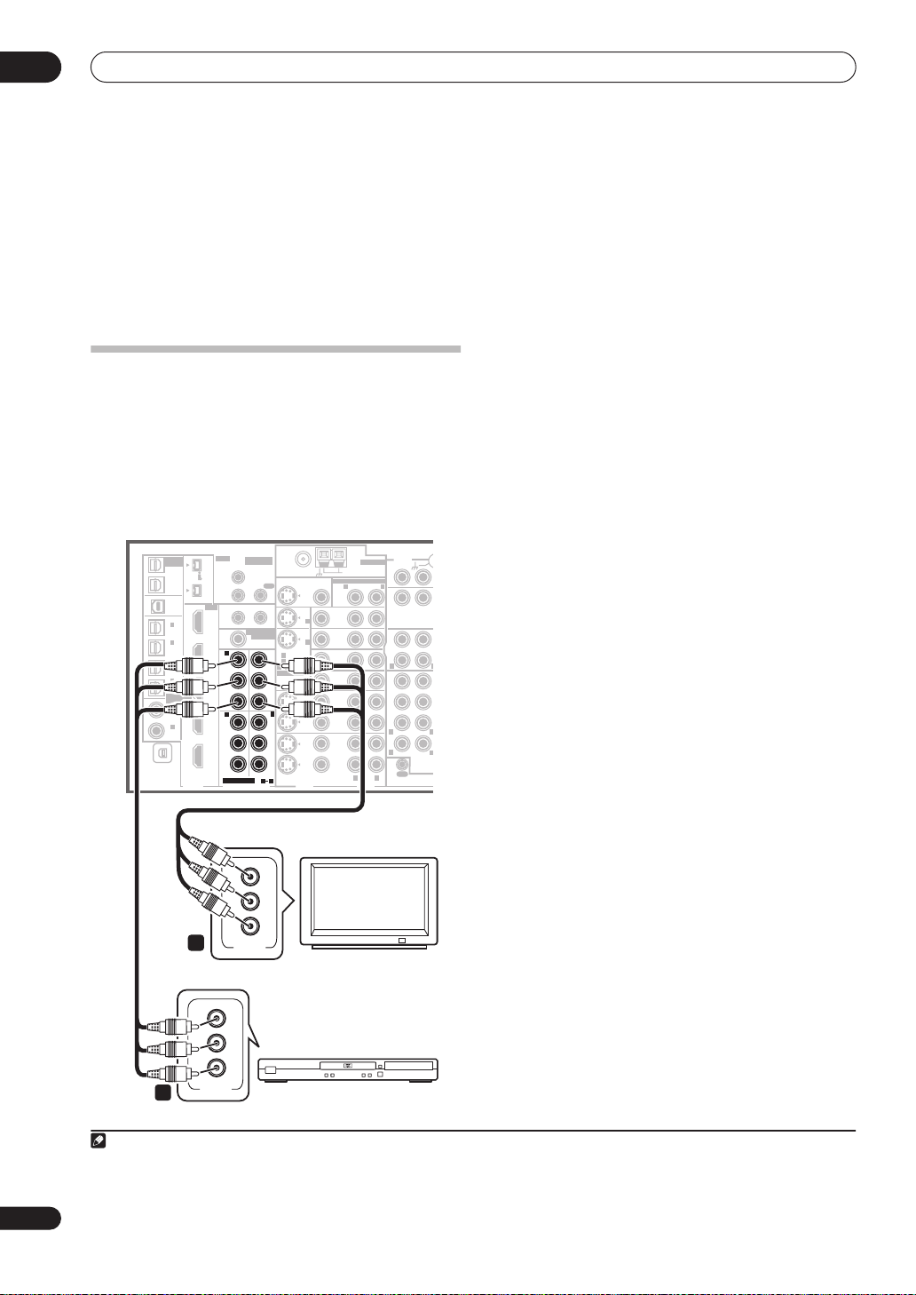
Using the component video jacks
Component video should give superior picture quality
when compared to composite or S-video. You can also
take advantage of progressive scan video (if your source
and TV are both compatible), which delivers a very stable,
flicker-free picture. See the manuals that came with your
TV and source component to check whether they are
compatible with progressive-scan video.
VSX-84TXSi
MULTI-ROOM
& SOURCE
/
OUT1
ROOM3
(
ZONE3
OUT2
USB
AUDIO
IN
IN
(
IN
(
VCR 1
IN
(
VCR 2
IN
(
IN
(
LD
IN
(CD)
XM
REC SEL
)
1
SAT
2
DVR/
3
DVR/
4
CD-R
ASSIGNABLE
1
DVD/
)
2
IN
IR
MULTI-ROOM
& SOURCE
)
MAIN ROOM(ZONE1
S400
IN1
(
)
AUDIO
ROOM2(ZONE2
IN2
S400
HDMI
IN1
1
(
DC OUT 12V TOTAL 50 mA MAX
)
ROOM2
(
ZONE2
IN2
)
1
IN
Y
)
IN3
B
P
)
4
1
P
R
21
IN4
2
IN
Y
B
P
OUT
P
R
ASSIGNABLE
COMPONENT VIDEO
DIGITAL
12 V TRIGGER
)
)
MULTI-ROOM
& SOURCE
MONITOR
OUT
OUT
OUT
IN
2
)
Y
B
P
P
R
3
Y
B
P
P
R
31
FM UNBAL 75 Ω
(
1
DVD/LD
IN
(TV)
2
IN
21
ASSIGNABLE
S - VIDEO
MONITOR
OUT
VIDEO
IN
IN
1
2
)
VIDEO
MULTI-ROOM & SOURCE
OUT
DVD/
LD
IN
TV
IN
SAT
IN
VIDEO /
GAME1
IN
OUT
DVR/
VCR 1
IN
OUT
DVR/
VCR 2
IN
AM LOOP
ROOM2(ZONE2
R
ANTENNA
R L
AUDIO
)
L
AUDIO
PHONO
IN
CD
IN
OUT
CD-R/
TAPE
IN
R
FR FL
SUB W.
SURROUND
R
R
OUT
CONTROL
SURROUND
MULTI CH
IN
CENTE
L
L
BACK
1 Connect the component video outputs of your
source to a set of ASSIGNABLE COMPONENT VIDEO
inputs.
Connect using a three-way component video cable.
• Since they are assignable, it doesn’t matter which
component video inputs you use for which source.
After connecting everything, you’ll need to assign the
component video inputs—see
The Input Setup menu
on page 63.
2 Connect the COMPONENT VIDEO OUT jacks to the
component video inputs on your TV or monitor.
Use a three-way component video cable.
14
En
Y
B
P
P
R
2
COMPONENT
VIDEO
Y
B
P
P
R
COMPONENT
VIDEO
1
TV
DVD player
Note
1• In order to record, you must connect the analog audio cables (the digital connection is for playback only).
• If your video component doesn’t have a digital audio output, you can skip this step.
2 If your recorder only has a coaxial digital output, you can connect it to one of the coaxial inputs on this receiver using a coaxial digital audio cable. When
you set up the receiver you’ll need to tell the receiver which input you connected the recorder to (see also
The Input Setup menu
on page 63).
Connecting your equipment
T
C
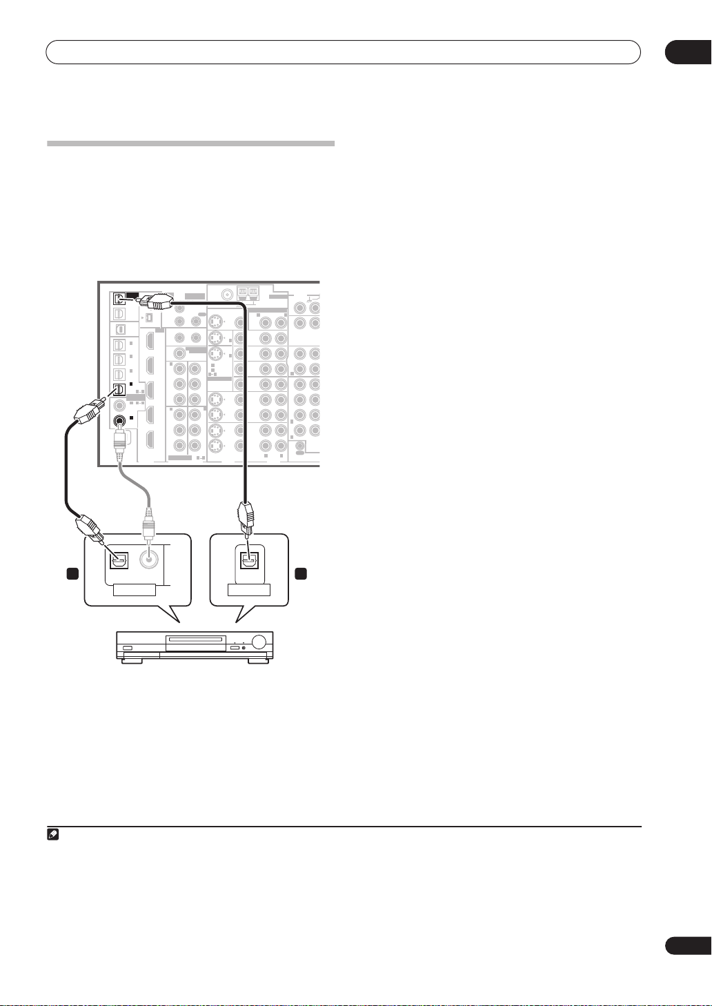
Connecting digital audio sources
This receiver has both digital inputs and outputs,
allowing you to connect digital audio components for
playback and for making digital recordings.
Most digital components also have analog connections.
See
Connecting analog audio sources
page if you want to connect these too.
VSX-84TXSi
MULTI-ROOM
IR
MULTI-ROOM
& SOURCE
)
MAIN ROOM(ZONE1
IN1
(
)
AUDIO
HDMI
IN1
IN2
IN3
IN4
OUT
ROOM2(ZONE2
IN2
12 V TRIGGER
1
(
DC OUT 12V TOTAL 50 mA MAX
ROOM2
MULTI-ROOM
(
)
ZONE2
1
IN
Y
B
P
PR
2
IN
Y
B
P
PR
ASSIGNABLE
COMPONENT VIDEO
)
& SOURCE
MONITOR
OUT
XM
& SOURCE
/
REC SEL
OUT1
ROOM3
(
ZONE3
OUT2
USB
AUDIO
IN
1
IN
(
SAT
2
IN
(
DVR/
VCR 1
3
IN
(
DVR/
VCR 2
4
IN
(
CD-R
ASSIGNABLE
1
IN
(
DVD/
LD
2
IN
(CD)
S400
)
S400
)
)
)
)
41
21
)
IN
DIGITAL
on the following
FM UNBAL 75 Ω
MONITOR
OUT
OUT
2
1
IN
)
2
IN
OUT
(
)
1
DVD/LD
IN
Y
(TV)
2
IN
21
ASSIGNABLE
B
P
PR
3
IN
Y
B
P
PR
S - VIDEO
VIDEO
31
VIDEO
ANTENNA
AM LOOP
MULTI-ROOM & SOURCE
ROOM2(ZONE2
R
OUT
DVD/
LD
IN
TV
IN
SAT
IN
VIDEO /
GAME1
IN
OUT
DVR/
VCR 1
IN
OUT
DVR/
VCR 2
IN
R L
AUDIO
)
L
PHONO
IN
CD
IN
OUT
CD-R/
TAPE
IN
R
FR FL
SUB W.
SURROUND
R
R
CONTROL
AUDIO
OUT
SURROUND
CEN
BACK
MULTI
IN
1 Connect an optical-type1 digital audio output on
your digital component to the DIGITAL 4 (CD-R) input.
Use an optical cable for the connection.
2 For recording equipment, connect one of the
optical-type DIGITAL outputs to a digital input on the
recorder.
Use an optical cable to connect to the
(VSX-84TXSi only)
illustration).
OUT2 (OUT1
2
DIGITAL OUT1
is shown in the
or
About the WMA9 Pro decoder
This unit has an on-board Windows Media® Audio 9
Professional
playback WMA9 Pro-encoded audio using a coaxial or
optical digital connection when connected to a WMA9
Pro-compatible player. However, the connected PC, DVD
player, set-top box, etc. must be able to output WMA9 Pro
format audio signals through a coaxial or optical digital
output.
3
(WMA9 Pro) decoder, so it is possible to
03
1 2
OPTICAL COAXIAL
DIGITAL OUT
OPTICAL
DIGITAL IN
CD-R, MD, DAT, etc.
Note
1• If your digital component only has a coaxial digital output, you can connect it to one of the coaxial inputs on this receiver using a coaxial cable. When
you set up the receiver you’ll need to tell the receiver which input you connected the component to (see also
• The digital outputs from other components can be connected to any spare digital audio inputs on this receiver. You can assign them when setting up
the receiver (see also
2• You must switch
• In order to record some digital sources, you must make analog connections as explained in
3
• Microsoft, Windows Media®, and the Windows logo are trademarks, or registered trademarks of Microsoft Corporation in the United States and/or other
countries.
• With WMA9 Pro, sound problems may occur depending on your computer system. Note that WMA9 Pro 96 kHz sources will be downsampled to 48 kHz.
The Input Setup menu
ROOM 3 ON
in
Using the multi-room controls
on page 63).
on page 59 to hear audio from the
Connecting analog audio sources
The Input Setup menu
DIGITAL OUT1
on page 63).
.
below.
15
En
03
E
T
Connecting your equipment
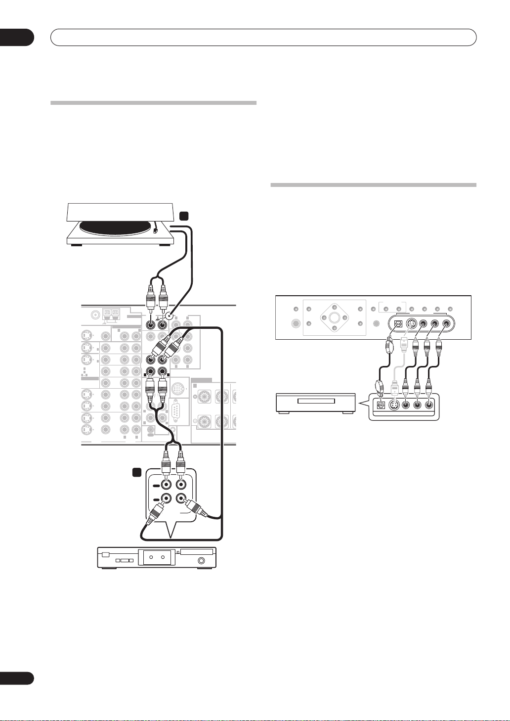
Connecting analog audio sources
This receiver features three stereo audio-only inputs. Two
of these inputs have corresponding outputs for use with
audio recorders.
One of the audio inputs (
turntable input which should not be used for any other
PHONO
) is a dedicated
2
Turntables only:
Connect the stereo audio outputs to
the PHONO inputs.
• If your turntable has a grounding wire, secure it to the
ground terminal on this receiver.
• If your turntable has line-level outputs (i.e., it has a
built-in phono pre-amp), connect it to the
CD
inputs
instead.
type of component. This input also has a grounding
terminal that most turntables require.
Connecting a component to the front
2
urntable
VSX-84TXSi
AUDIO PRE OUT
ANTENNA
PHONO
MONITOR
OUT
IN
IN
VIDEO
1
2
)
VIDEO
AM LOOP
MULTI-ROOM & SOURCE
ROOM2(ZONE2
R
OUT
DVD/
LD
IN
TV
IN
SAT
IN
VIDEO /
GAME1
IN
OUT
DVR/
VCR 1
IN
OUT
DVR/
VCR 2
IN
R L
AUDIO
)
L
IN
CD
IN
OUT
CD-R/
TAPE
IN
R
FR FL
SUB W.
SUR-
ROUND
R
R
OUT
CONTROL
SURROUND
BACK
MULTI CH
IN
FM UNBAL 75 Ω
(
1
DVD/LD
N
(TV)
2
N
21
ASSIGNABLE
S - VIDEO
CENTER
LR
FRONT
CENTER
SUB W.
SURROUND
SURROUND
BACK
(
)
Single
LAR
L
iPod
SPEAKERS
IN
RL
L
L
RS-232C
IN
FRONT
C
panel inputs
The front panel inputs comprise a composite video jack
(
VIDEO
), an S-Video jack (
inputs (
AUDIO L/R
(
DIGITAL
). You can use these connections for any kind of
audio/video component, but they are especially
convenient for portable equipment such as camcorders,
video games and portable audio/video equipment.
SPEAKERS
PHONES
TV game, video camera, etc.
(TUNE +)
AV
PARAMETER
(ST –) (ST +)
ENTER
SETUP
(TUNE –)
• Select these inputs using
the
INPUT SELECTOR
VIDEO/GAME 2
S-VIDEO
), stereo analog audio
) and an optical digital audio input
MULTI – ROOM &
VIDEO
SIGNAL
SELECT
VIDEO/GAME 2 INPUT
SBch
SELECT
PROCESSING
(remote) or
STEREO
RETURN
TUNER
EDIT
BAND
SOURCE/REC SEL
CONTROL ON/OFF
MCACC
SETUP MIC
DIGITAL IN S-VIDEO VIDEO L RAUDIO
VIDEO OUTPUT
DIGITAL OUT
INPUT SELECT
dial (front panel) to select
.
16
En
1
OUT
PLAY
IN
REC
R L
AUDIO IN/OUT
Tape deck, etc.
1 Connect the analog audio outputs of the source
component to one of the AUDIO inputs.
Connect using a stereo RCA/phono jack audio cable.
• If you’re connecting a tape deck, MD recorder, etc.,
connect the analog audio outputs (
OUT
) to the
analog audio inputs on the recorder.
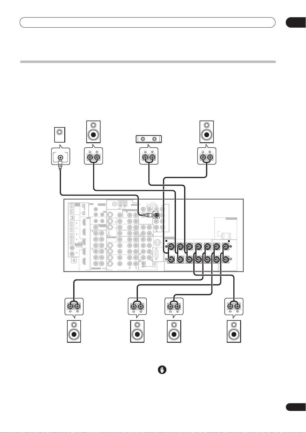
Connecting your equipment
Installing your speaker system
To take full advantage of the receiver’s surround sound
capabilities connect front, center, surround and
surround back speakers, as well as a subwoofer.
Although this is ideal, other configurations with fewer
speakers—no subwoofer or no center speaker, or even
no surround speakers—will work. At the very least, front
left and right speakers only are necessary. Note that your
main surround speakers should always be connected as
a pair, but you can connect just one surround back
speaker if you like (it must be connected to the left
surround back terminal). You can use speakers with a
nominal impedance between 6
Switching the speaker impedance
to use speakers with an impedance of less than 8
Ω
to 16 Ω (please see
on page 68 if you plan
Ω
).
03
Subwoofer
LINE LEVEL
INPUT
MULTI-ROOM
MULTI-ROOM
& SOURCE
& SOURCE
/
REC SEL
/
REC SEL
OUT1
OUT1
ROOM3
ROOM3
(
)
(
)
ZONE3
ZONE3
OUT2
OUT2
USB
USB
AUDIO
AUDIO
IN
IN
1
1
IN
IN
(
)
(
)
SAT
SAT
2
2
IN
IN
(
(
DVR/
DVR/
)
)
VCR 1
VCR 1
3
3
IN
IN
(
(
DVR/
DVR/
)
)
VCR 2
VCR 2
4
4
IN
IN
(
)
(
)
CD-R
CD-R
1
1
ASSIGNA-
ASSIGNABLE
BLE
1
1
IN
IN
(
(
DVD/
DVD/
)
)
LD
LD
2
2
IN
IN
(CD)
(CD)
IN
IN
XM
XM
DIGITAL
DIGITAL
VSX-84TXSi
FRONT
FRONT
CENTER
CENTER
Front
right
SURROUND
SURROUND
SWITCHED 100 W(0.8A) MAX
SWITCHED 100 W(0.8A) MAX
SURROUND BACK /
SURROUND BACK /
AC OUTLET
AC OUTLET
(
)
(
)
Single
Single
B
B
Front
left
IR
IR
MULTI-ROOM
MULTI-ROOM
& SOURCE
& SOURCE
)
)
MAIN ROOM(ZONE1
MAIN ROOM(ZONE1
FM UNBAL 75 Ω
S400
S400
IN1
IN1
(
)
(
)
AUDIO
AUDIO
IN2
IN2
S400
S400
HDMI
HDMI
IN1
IN1
ROOM2
ROOM2
(
(
ZONE2
ZONE2
IN2
IN2
IN
IN
IN3
IN3
4
4
21
21
IN4
IN4
IN
IN
OUT
OUT
)
)
ROOM2(ZONE2
ROOM2(ZONE2
12 V TRIGGER
12 V TRIGGER
1
1
(
(
DC OUT 12V TOTAL 50 mA MAX
DC OUT 12V TOTAL 50 mA MAX
MULTI-ROOM
MULTI-ROOM
& SOURCE
& SOURCE
MONITOR
MONITOR
)
)
OUT
OUT
1
1
Y
Y
P
P
B
B
PR
PR
2
2
Y
Y
P
P
B
B
PR
PR
ASSIGNABLE
ASSIGNABLE
COMPONENT VIDEO
COMPONENT VIDEO
FM UNBAL 75 Ω
MULTI-ROOM & SOURCE
MULTI-ROOM & SOURCE
MONITOR
MONITOR
OUT
OUT
OUT
OUT
2
2
OUT
OUT
Y
Y
P
P
B
B
PR
PR
3
3
IN
IN
Y
Y
P
P
B
B
PR
PR
31
31
)
)
IN
IN
IN
IN
ASSIGNABLE
ASSIGNABLE
S - VIDEO
S - VIDEO
OUT
OUT
DVD/
DVD/
LD
LD
1
1
IN
IN
IN
IN
TV
TV
IN
IN
2
2
IN
IN
(
)
(
)
1
1
DVD/LD
DVD/LD
SAT
SAT
(TV)
(TV)
2
2
IN
IN
21
21
VIDEO /
VIDEO /
GAME1
GAME1
IN
IN
OUT
OUT
DVR/
DVR/
VCR 1
VCR 1
IN
IN
OUT
OUT
DVR/
DVR/
VCR 2
VCR 2
IN
IN
VIDEO
VIDEO
VIDEO
VIDEO
AM LOOP
AM LOOP
R
R
ROOM2(ZONE2
ROOM2(ZONE2
R L
R L
AUDIO
AUDIO
ANTENNA
ANTENNA
)
)
L
L
CD-R/
CD-R/
TAPE
TAPE
Center
AUDIO PRE OUT
AUDIO PRE OUT
PHONO
PHONO
IN
IN
CD
CD
IN
IN
OUT
OUT
IN
IN
L
R
L
R
FR FL
FR FL
CENTER
CENTER
SUB W.
SUB W.
SUR-
SURROUND
ROUND
L
R
R
L
L
R
R
L
SURROUND
SURROUND
BACK
BACK
MULTI CH
MULTI CH
IN
IN
OUT
OUT
CONTROL
CONTROL
LR
LR
FRONT
FRONT
CENTER
CENTER
SUB W.
SUB W.
SUR-
SURROUND
ROUND
SUR-
SURROUND
ROUND
BACK
BACK
(
)
(
)
Single
Single
LAR
LAR
iPod
iPod
SPEAKERS
SPEAKERS
IN
IN
RL R LRL
RL R LRL
RS-232C
RS-232C
IN
IN
Surround
left
Surround
back left
Connecting the speakers
Each speaker connection on the receiver comprises a
positive (+) and negative (–) terminal. Make sure to
match these up with the terminals on the speakers
themselves.
Surround
right
Surround
back right
Caution
• Make sure that all the bare speaker wire is twisted
together and inserted fully into the speaker terminal.
If any of the bare speaker wire touches the back panel
it may cause the power to cut off as a safety measure.
17
En
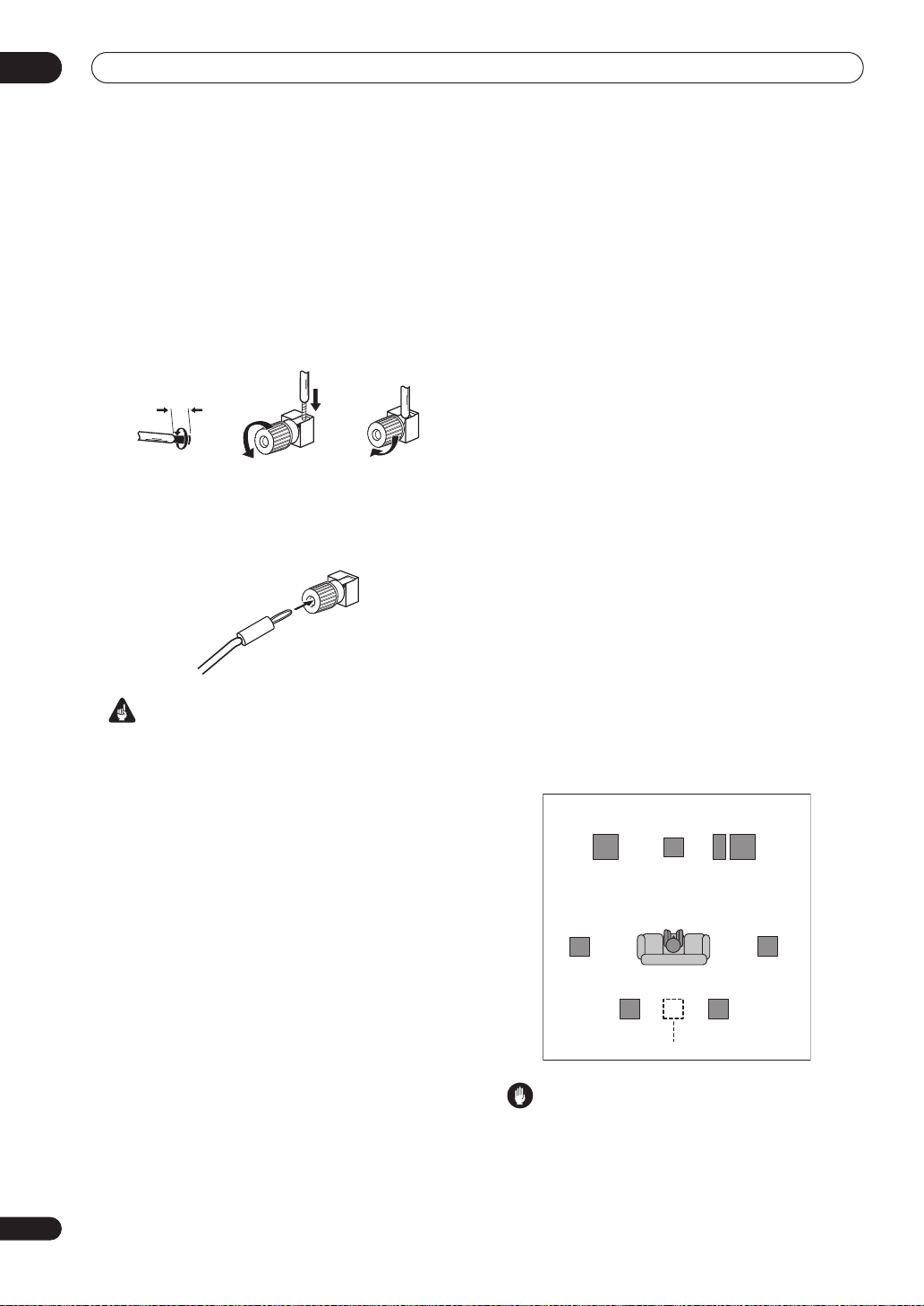
03
Connecting your equipment
Bare wire connections
Make sure that the speaker cable you’re going to use is
3
properly prepared with about
/8 in. (10 mm) of insulator
stripped from each wire, and the exposed wire strands
twisted together (
fig. A
).
To connect a terminal, unscrew the terminal a few turns
until there is enough space to insert the exposed wire
(
fig. B
). Once the wire is in position, tighten the terminal
until the wire is firmly clamped (
fig. C
).
fig. A fig. B fig. C
3
/8 in. (10mm)
Banana plug connections
If you want to use speaker cables terminated with banana
plugs, screw the speaker terminal fully shut then plug the
banana plug into the end of the speaker terminal.
Important
• Please refer to the manual that came with your
speakers for details on how to connect the other end
of the speaker cables to your speakers.
•
Other connections
on page 47 provides greater detail
on alternate speaker setups, such as using speaker
system B (page 55), bi-amping (page 56) and biwiring (page 56).
• If you are using a THX certified subwoofer use the
THX INPUT
has one) or switch the filter position to
jack on the subwoofer (if your subwoofer
THX
on your
subwoofer.
• When placing speakers near the TV, we recommend
using magnetically shielded speakers to prevent
possible interference, such as discoloration of the
picture when the TV is switched on. If you do not have
magnetically shielded speakers and notice
discoloration of the TV picture, move the speakers
farther away from the TV.
• If you're using a center speaker, place the front
speakers at a wider angle. If not, place them at a
narrower angle.
• Place the center speaker above or below the TV so
that the sound of the center channel is localized at
the TV screen. Also, make sure the center speaker
does not cross the line formed by the leading edge of
the front left and right speakers.
• It is best to angle the speakers towards the listening
position. The angle depends on the size of the room.
Use less of an angle for bigger rooms.
• Surround and surround back speakers should be
positioned a foot-and-a-half to three feet (60 cm to 90
cm) higher than your ears and titled slight downward.
Make sure the speakers don't face each other. For
DVD-Audio, the speakers should be more directly
behind the listener than for home theater playback.
• Try not to place the surround speakers farther away
from the listening position than the front and center
speakers. Doing so can weaken the surround sound
effect.
• To achieve the best possible surround sound, install
your speakers as shown below. Be sure all speakers
are installed securely to prevent accidents and
improve sound quality.
Surround
left
Front
left
Center
Subwoofer
Front
right
Surround
right
18
En
Placing the speakers
Where you put your speakers in the room has a big effect
on the quality of the sound. The following guidelines
should help you to get the best sound from your system.
• The subwoofer can be placed on the floor. Ideally, the
other speakers should be at about ear-level when
you’re listening to them. Putting the speakers on the
floor (except the subwoofer), or mounting them very
high on a wall is not recommended.
• For the best stereo effect, place the front speakers
6 ft. to 9 ft. apart, at equal distance from the TV.
Listening position
Surround back Surround back
left right
Single surround back speaker
Caution
• Make sure that all speakers are securely installed.
This not only improves sound quality, but also
reduces the risk of damage or injury resulting from
speakers being knocked over or falling in the event of
external shocks such as earthquakes.
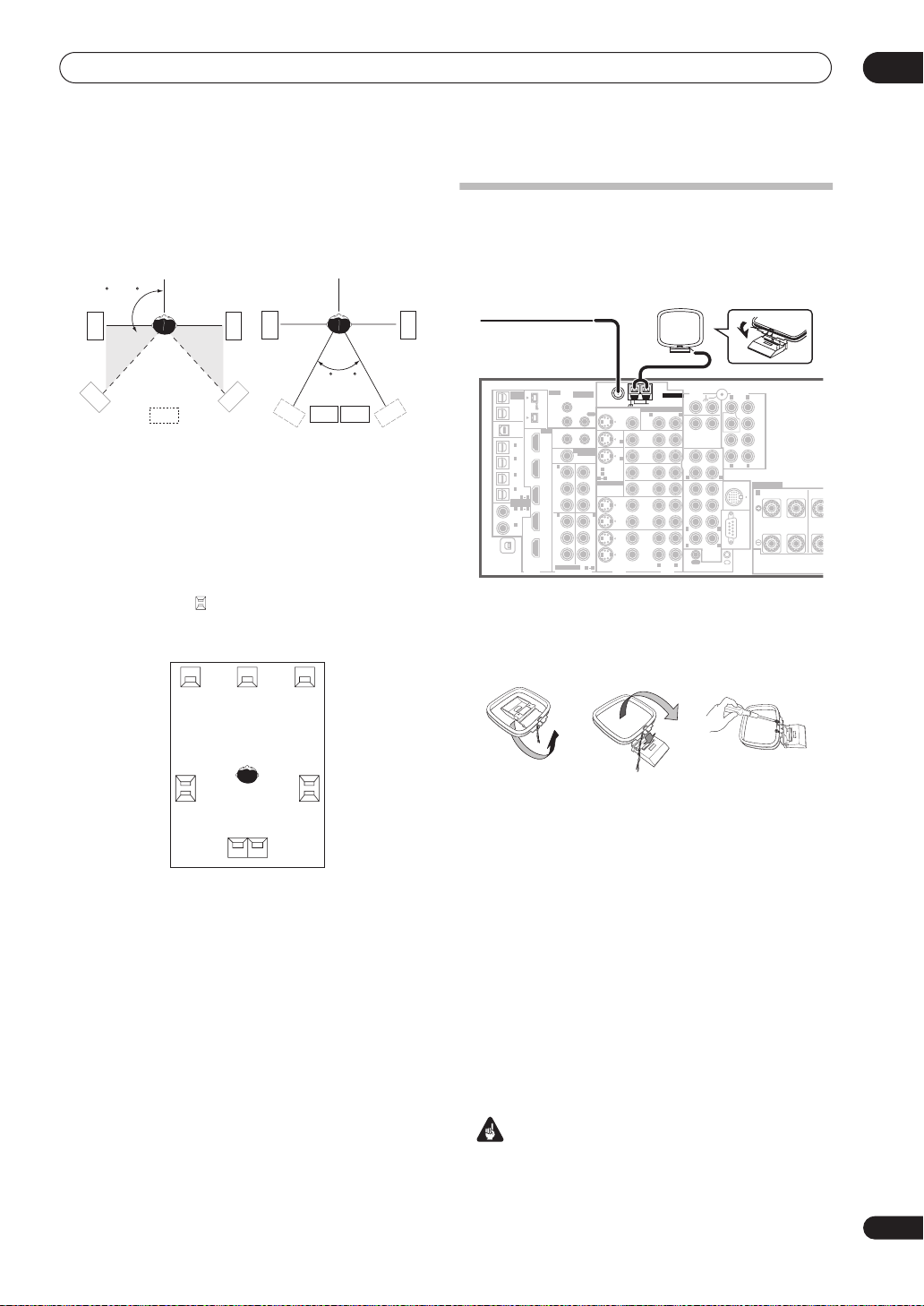
Connecting your equipment
The diagrams below show suggested surround and
surround back speaker orientation. The first diagram (
A
) shows orientation with one surround back speaker (or
none) connected. The second (
with two surround back speakers connected.
90~120
SL
fig. B
) shows orientation
SL
SR
03
fig.
Connecting antennas
The supplied antennas provide a simple way to listen to
AM and FM radio. If you find that reception quality is
poor, an outdoor antenna should give you better sound
quality—see
SR
Connecting external antennas
below.
SL
SB
fig. A
SR
SBL
SBL
SBR
SBR
fig. B
• If you have two surround back speakers THX
recommends placing them together and the same
distance from your listening position (see below).
THX speaker system setup
If you have a complete THX speaker system, follow the
diagram below to place your speakers. Note that the
surround speakers ( indicates bi-polar radiating
speakers) should output at an angle parallel to the
listener.
0~60
L
SL
Surround
• If you have two surround back speakers THX
recommends placing them together and the same
distance from your listening position for the following
THX modes:
MUSICMODE
See also
THX Select2 CINEMA, THX
and
THX Audio Setting
settings that will give you the best sound experience
when using the Home THX modes (on page 28).
CR
SR
Surround
SBL SBR
Surround back
THX GAMES MODE
on page 46 to make the
.
VSX-84TXSi
MULTI-ROOM
IR
& SOURCE
/
REC SEL
OUT1
ROOM3
(
)
ZONE3
OUT2
USB
AUDIO
IN
1
IN
(
)
SAT
2
IN
(
DVR/
VCR 1
3
IN
(
DVR/
VCR 2
4
IN
(
)
CD-R
ASSIGNABLE
1
IN
(
DVD/
)
LD
2
IN
(CD)
IN
XM
MULTI-ROOM
& SOURCE
)
MAIN ROOM(ZONE1
IN1
ROOM2(ZONE2
IN2
12 V TRIGGER
1
(
DC OUT 12V TOTAL 50 mA MAX
ROOM2
(
)
ZONE2
1
IN
Y
B
P
PR
2
IN
Y
B
P
PR
ASSIGNABLE
COMPONENT VIDEO
)
MULTI-ROOM
& SOURCE
MONITOR
OUT
FM UNBAL 75 Ω
MONITOR
OUT
OUT
2
1
IN
)
2
IN
OUT
(
)
1
DVD/LD
IN
Y
(TV)
2
IN
21
ASSIGNABLE
B
P
PR
3
IN
Y
B
P
PR
S - VIDEO
VIDEO
31
VIDEO
S400
(
)
AUDIO
S400
HDMI
IN1
IN2
)
)
IN3
41
21
IN4
OUT
DIGITAL
AM LOOP
MULTI-ROOM & SOURCE
ROOM2(ZONE2
R
OUT
DVD/
LD
IN
TV
IN
SAT
IN
VIDEO /
GAME1
IN
OUT
DVR/
VCR 1
IN
OUT
DVR/
VCR 2
IN
R L
AUDIO
ANTENNA
)
AUDIO PRE OUT
PHONO
IN
L
CD
IN
OUT
CD-R/
TAPE
IN
R
FR FL
CENTER
SUB W.
SURROUND
R
R
SURROUND
BACK
MULTI CH
IN
OUT
CONTROL
LR
FRONT
CENTER
SUB W.
SURROUND
SURROUND
BACK
(
)
Single
LAR
L
iPod
SPEAKERS
IN
L
L
RS-232C
IN
FRONT
RL
CENT
AM loop antenna
1 Assemble the stand as shown in the illustration.
fig. A fig. B fig. C
• Bend the stand in the direction indicated (fig. A).
• Clip the loop into the stand (fig. B).
• It’s possible to fix the AM antenna to a wall (fig. C).
Before fixing, make sure that the reception is
satisfactory.
2 Pull off the protective shields of both AM antenna
wires.
3 Press the
AM LOOP
and insert one wire into each terminal.
4 Release the tabs to secure the AM antenna wires.
5 Place the AM antenna on a flat surface and point in
the direction giving the best reception.
Avoid placing near computers, television sets or other
electrical appliances and do not let it come into contact
with metal objects.
antenna terminal tabs to open
Important
• The signal ground () is designed to reduce noise
that occurs when an antenna is connected. It is not
an electrical safety ground.
19
En
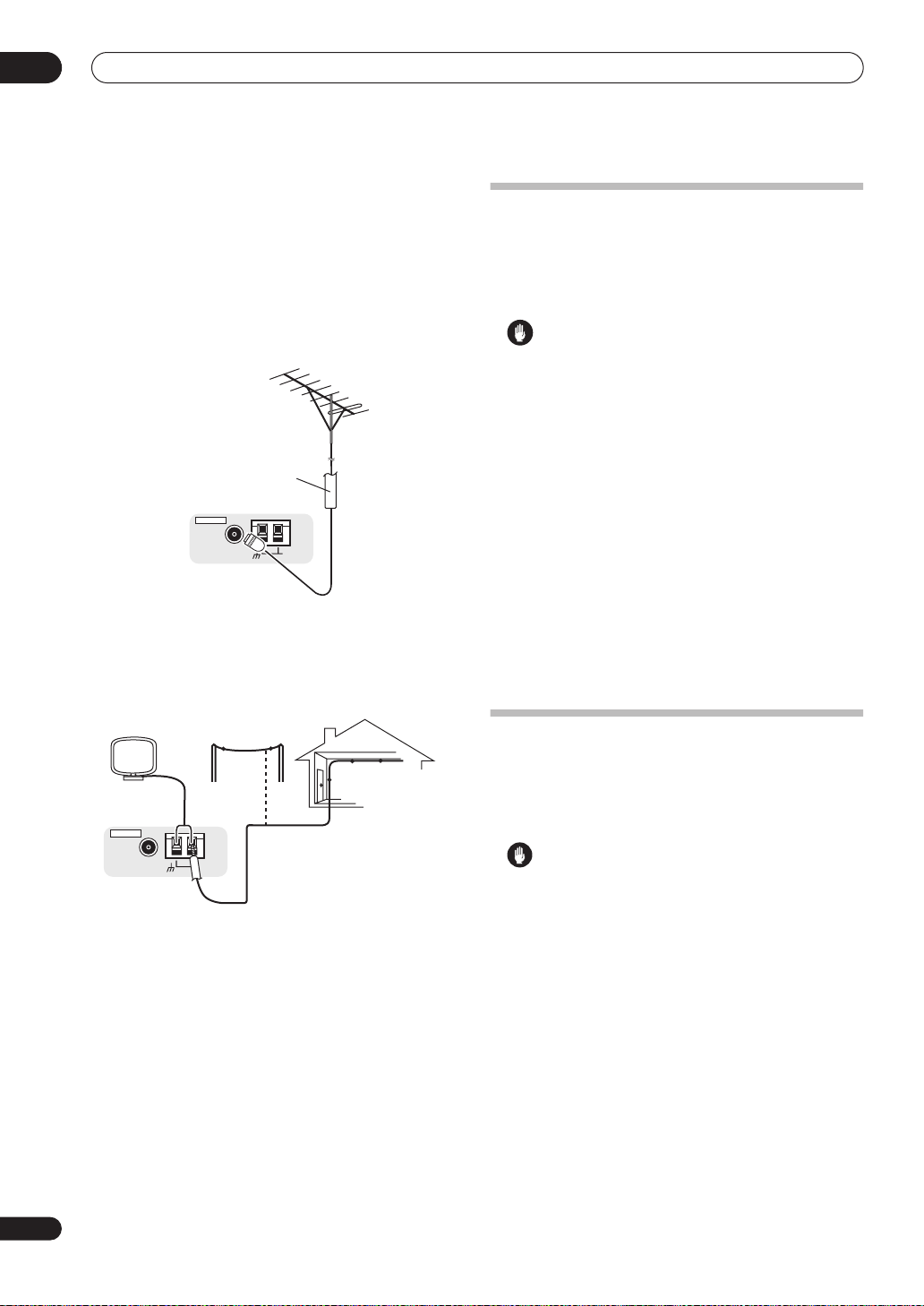
03
Connecting your equipment
FM wire antenna
• Connect the FM wire antenna to the FM UNBAL
75
Ω
in the same way as the AM antenna.
For best results, extend the FM antenna fully and fix to a
wall or door frame. Don’t drape loosely or leave coiled up.
Connecting external antennas
To improve FM reception connect an external FM
antenna to the
To improve AM reception, connect a 15 ft. to 18 ft. length
of vinyl-coated wire to the
disconnecting the supplied AM loop antenna.
For the best possible reception, suspend horizontally
outdoors.
FM UNBAL 75 Ω.
75 Ω coaxial cable
ANTENNA
FM UNBAL 75 Ω
AM LOOP
AM LOOP
terminals without
Plugging in the
receiver
Only plug in after you have connected all your
components to this receiver, including the speakers.
• Plug the AC power cord into a convenient AC power
outlet.
Caution
• Handle the power cord by the plug part. Do not pull
out the plug by tugging the cord, and never touch the
power cord when your hands are wet, as this could
cause a short circuit or electric shock. Do not place
the unit, a piece of furniture, or other object on the
power cord or pinch the cord in any other way. Never
make a knot in the cord or tie it with other cables. The
power cords should be routed so that they are not
likely to be stepped on. A damaged power cord can
cause a fire or give you an electric shock. Check the
power cord once in a while. If you find it damaged,
ask your nearest Pioneer authorized independent
service company for a replacement.
• The receiver should be disconnected by removing the
mains plug from the wall socket when not in regular
use, e.g., when on vacation.
• Make sure the blue
STANDBY/ON
light has gone
out before unplugging.
20
En
ANTENNA
FM UNBAL 75 Ω
Outdoor antenna
15 ft. to 18 ft.
AM LOOP
Indoor antenna
(vinyl-coated wire)
AC outlet
Power supplied through this outlet is turned on and off by
the receiver's power switch. Total electrical power
consumption of connected equipment should not exceed
100 W (0.8 A).
Caution
•
Do not connect a TV set
appliance to this unit's AC outlet.
• Do not connect appliances with high power
consumption to the AC outlet in order to avoid
overheating and fire risk. This can also cause the
receiver to malfunction.
• Since a subwoofer or power amplifier can exceed the
100 W maximum when playing sources at a high
volume, this type of equipment should not be
connected to the AC outlet.
, monitor, heater, or similar
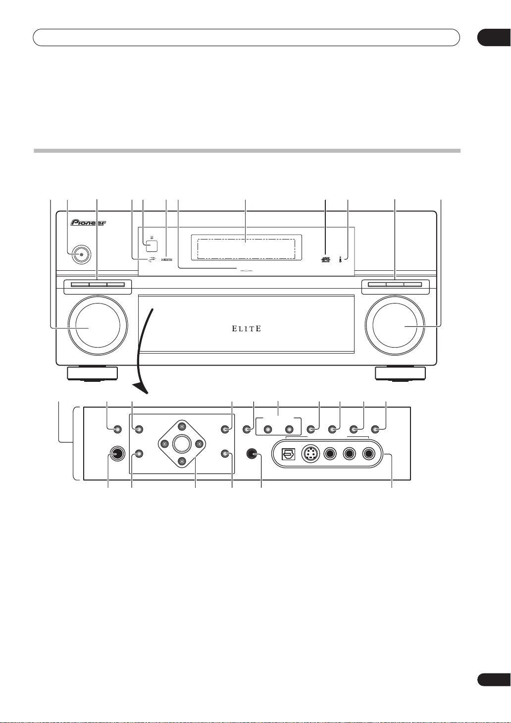
Controls and displays
Chapter 4:
Controls and displays
Front panel
Illustration shows the VSX-84TXSi front panel
04
1 6 8245 97101112
SELECTOR
13
INPUT
STANDBY/ON
PHASE
CONTROL
3
MCACC
POSITION
AUTO SURR/
STREAM DIRECT
14
SPEAKERS
PHONES
PHASE
CONTROL
15
AV
PARAMETER
(ST –) (ST +)
SETUP
(TUNE +)
ENTER
(TUNE –)
DIGITAL PRECISION
PROCESSING
16 17 19
TUNER
EDIT
RETURN
BAND
18 21 22
MULTI – ROOM &
SOURCE/REC SEL
CONTROL ON/OFF
MCACC
SETUP MIC
AUDIO/VIDEO MULTI-CHANNEL RECEIVER VSX-84TXSi
20
SIGNAL
SELECT
SBch
PROCESSING
VIDEO
SELECT
VIDEO/GAME 2 INPUT
DIGITAL IN S-VIDEO VIDEO L RAUDIO
STEREO
HOME
STANDARD
SURROUND
ADVANCED
SURROUND
MASTER
VOLUME
THX
23
1
INPUT SELECTOR
24
dial
25 27 28
Use to select an input source.
2
STANDBY/ON
Switches the receiver between on and standby. Power
indicator lights when the receiver is on.
3
PHASE CONTROL – Press to switch on/off phase
correction (page 9).
MCACC POSITION
– Press to switch between
MCACC presets (page 29).
AUTO SURR
/
STREAM DIRECT
– Press to select
Auto Surround (page 27) or Stream Direct (page 29)
listening.
4
PHASE CONTROL
indicator
Lights when Phase Control is switched on (page 9).
26
5 Remote sensor
Receives the signals from the remote control (see
Operating range of remote control unit
on page 22).
6 HDMI indicator
Blinks when connecting an HDMI-equipped component;
lights when the component is connected (page 50).
7 Digital Precision Processing indicator
Lights to indicate digital processing (for example, it
disappears when Pure Direct (page 29) is on, or when
listening through the multichannel analog inputs).
8 Character display
See
Display
on page 23.
21
En
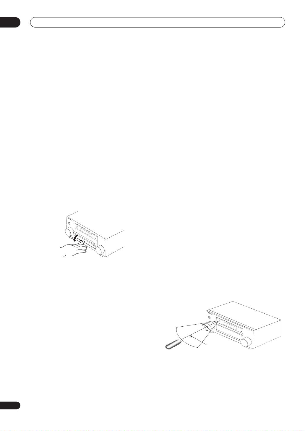
04
Controls and displays
9 MCACC indicator
Lights when one of the MCACC presets (page 29) is
selected.
10 i.LINK indicator
(VSX-84TXSi only)
Lights when an i.LINK-Audio-equipped component is
selected (page 51).
DIGITAL VIDEO SCALER indicator
Lights when
PURE
Resolution
is set to a setting other than
(for example, when the video input signal is
(VSX-82TXS only)
upscaled) (page 66).
11 Listening mode buttons
HOME THX
– Press to select a Home THX listening
mode (page 28).
STANDARD SURROUND
decoding and to switch between the various
– Press for Standard
2
Pro
Logic IIx and Neo:6 options (page 27).
ADVANCED SURROUND
– Use to switch between
the various surround modes (page 28).
12
MASTER VOLUME
dial
13 Front panel controls
To access the front panel controls, push gently on the
lower third portion of the panel with your finger.
S
T
A
N
D
B
Y
/
O
N
20 SIGNAL SELECT
Use to select an input signal (page 30).
21
SBch PROCESSING
Selects the surround back channel mode (page 30) or
virtual surround back mode (page 30).
22 STEREO
Switches to stereo playback (page 29).
23
PHONES
jack
Use to connect headphones. When the headphones are
connected, there is no sound output from the speakers.
24
SETUP
Press to access the System Setup menu (see page 34).
25
(TUNE/ST +/–) /
ENTER
Use the arrow buttons when setting up your surround
sound system (see page 34). Use the
to find radio frequencies and use
TUNE +/–
ST +/–
buttons
to find preset
stations (page 33).
26
RETURN
Press to confirm and exit the current menu screen.
27 MCACC SETUP MIC jack
Use to connect the supplied microphone.
28
VIDEO/GAME 2 INPUT
See
Connecting a component to the front panel inputs
on
page 16.
14
SPEAKERS
Use to change the speaker system (page 55).
15
AV PARAMETER
Use to access the AV options (page 66).
16
TUNER EDIT
Use with
/
to memorize and name stations for recall
(page 33).
17 BAND
Switches between AM and FM radio bands (page 32).
18 MULTI ROOM & SOURCE / REC SEL controls
If you’ve made multi-room connections (see
listening
sub room from the main room (see
controls
You will also need to use the
recording a source (see
recording
on page 57) use these controls to control the
Using the multi-room
on page 59).
REC SEL
Making an audio or a video
on page 67).
Multi-room
controls when
19 VIDEO SELECT
Press repeatedly to select the video source (page 68).
Operating range of remote control unit
The remote control may not work properly if:
• There are obstacles between the remote control and
the receiver's remote sensor.
• Direct sunlight or fluorescent light is shining onto the
remote sensor.
• The receiver is located near a device that is emitting
infrared rays.
• The receiver is operated simultaneously with another
infrared remote control unit.
S
T
A
N
D
B
Y
/O
N
A
U
D
IO
30
30
7m (23 ft.)
/
V
I
D
EO
M
U
L
T
IC
H
A
N
N
E
L
R
E
C
E
I
V
E
R
22
En
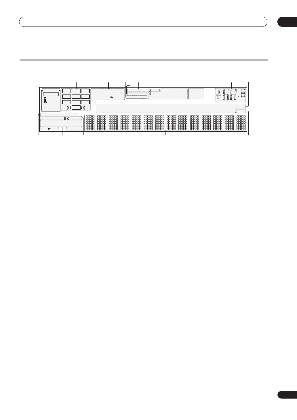
Controls and displays
Display
04
1
SIGNAL
SIGNAL
AUTO
HDMI
DIGITAL
ANALOG
STREAM
PRO LOGIC
2
ADV.SURROUND
THX
STEREO
AB
SP
indicators
21 3 876 91011
2
SBR
DIGITAL
WMA9 Pro
DSD PCM
CD
CD-R
L C R
SL S SR
SBL SB
LFE
DIRECT
N
eo
STANDARD
SLEEP
14
: 6
DTS
96/24
TUNER
PHONO
5
4
VIDEO
MULTI-ROOM
OVER ATT
MULTI IN
Light to indicate the currently selected input signal.
AUTO
lights when the receiver is set to select the input
signal automatically (page 30).
2 Program format indicators
These change according to which channels are active in
digital sources.
L
– Left front channel
C
– Center channel
R
– Right front channel
SL
– Left surround channel
S
– Surround channel (mono)
SR
– Right surround channel
SBL
– Left surround back channel
SB
– Surround back channel (mono)
SBR
– Right surround back channel
LFE
– Low frequency effects channel (the
an LFE signal is being input)
((( )))
indicators light when
3 Digital format indicators
Light when a signal encoded in the corresponding format
is detected (
DSDPCM
lights during DSD (Digital
Stream Direct) to PCM conversion with SACDs).
4
OVER
/
OVER
is too high.
(
ANALOG ATT
5
MULTI-ROOM
ATT
lights to indicate that the level of an analog source
ATT
lights when you use the attenuator
) to reduce it.
Lights when the multi-room feature is active (page 57).
6
VIDEO CONV.
Lights when digital video conversion is switched on (see
Setting the AV options
on page 66).
7 V.SB
Lights during Virtual surround back processing
(page 30).
8 Sound processing indicators
Light according to the active AV parameter(s) (page 66).
9
TUNER
indicators
TUNED
– Lights when a broadcast is being received.
CONV. V.SB DNR
DIALOGUE LOUDNESS
Hi-bit/sampling
iPod
MIDNIGHT TUNED
DVDTVSAT
DVR
171312 15 1816
STEREO
– Lights when a stereo FM broadcast is
TONE
STEREO
MONO
VIDEO
[
1
HDMI
]
[
2
USB XM
[
][
]
]
4
3
SR+
being received in auto stereo mode.
MONO
– Lights when the mono mode is set using
the
MPX
button.
10 Master volume level
Shows the overall volume level.
minimum level, and
+12dB
–80dB
indicates the
indicates the maximum level.
11 Input source indicators
Light to indicate the input source you have selected.
12
STREAM DIRECT
Lights when Direct / Pure Direct is selected (page 29).
13 Speaker indicators
Lights to indicate the current speaker system, A and/or
(page 55).
14 Listening mode indicators
THX
– Lights when one of the Home THX modes is
selected.
ADV. SURROUND
– Lights when one of the
Advanced Surround modes has been selected.
STEREO
on (see
STANDARD
Surround modes is switched on (see
surround sound
15
SLEEP
– Lights when stereo listening is switched
Listening in stereo
on page 29).
– Lights when one of the Standard
Listening in
on page 27).
Lights when the receiver is in sleep mode (page 68).
16 Matrix decoding format indicators
2
PRO LOGIC IIx
Logic II /
2Pro Logic IIx decoding (page 27).
– This lights to indicate 2Pro
Neo:6 – When one of the Neo:6 modes of the receiver
is on, this lights to indicate Neo:6 processing
(page 27).
17 Character display
Displays various system information.
18
SR+
Lights when the SR+ mode is switched on (page 61).
dB
B
23
En
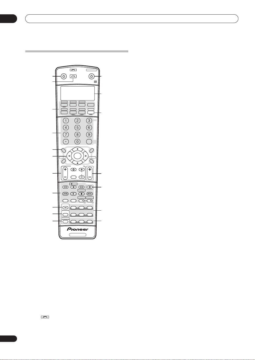
04
Controls and displays
Remote control
TV VIDEO 2
VIDEO 1 TV CONT
XM RADIO
TUNER
DIMMER
TUNE
ENTER
TUNE
TV CONTROL
TV CH
REC
DTV INFO
REC STOP
HDD
CH
PHOTO
SBch
STANDARD
THX
MCACC S.DIRECT
VIDEO
SEL
SYSTEM OFF
ROOM2/3
RECEIVER
CLASS
ENTER
CH LEVEL
MENU
T.EDIT
RETURN
BAND
VOL
MUTE
MEMORY
DVD
CH
STEREO
ADV. SURR
SHIFT
ANALOG
ATT
S.RETRIEVER
DISC
12
13
14
15
16
17
18
for
INPUT
INPUT
RECEIVER SOURCE
1
SELECT
2
CD
DVD SAT
DVR2
DVR1
CD-R
i Pod
SLEEP
+
SR
3
4
D.ACCESS
+
10
AV PARAMETER
TOP MENU
5
6
7
8
9
10
11
DTV MENU
SETUP
CATEGORY
GUIDE
TV VOL
MPX
AUDIO SUBTITLE
DISP
STATUS
MULTI OPE
SHIFT
ST ST
INPUT
SELECT
SIGNAL SEL
PHASE
RECEIVER
The remote has been conveniently color-coded according
to component control using the following system (press
the corresponding input source button to access):
•
Green
– Receiver controls (see below)
Red
– DVD controls (page 75)
•
•
Blue
– Tuner/XM Radio controls (page 32)
Yellow
•
•
– iPod controls (page 47)
White
– Other controls (page 75)
1 RECEIVER
This switches between standby and on for this receiver.
2
INPUT SELECT
Use to select the input source (use
SELECT
).
3 Input source buttons
Press to select control of other components (see
Controlling the rest of your system
on page 71).
4 Number buttons and other receiver/component
controls
Use the number buttons to directly select a radio
frequency (page 32) or the tracks on a CD, DVD, etc.
DISC (ENTER)
can be used to enter commands for TV or
DTV, and also to select a disc in a multi-CD player.
Press
RECEIVER
SLEEP
first to access:
– Use to put the receiver in sleep mode and
select the amount of time before sleep (page 68).
VIDEO SEL
– Press repeatedly to select the video
source (page 68).
ANALOG ATT
– Attenuates (lowers) the level of an
analog input signal to prevent distortion (page 68).
SR+
– Switches the SR+ mode on/off (page 61).
S. RETRIEVER
– Press to restore CD quality sound to
compressed audio sources (page 31).
DIMMER
Press
D.ACCESS
– Dims or brightens the display (page 68).
TUNER
first to access:
– After pressing, you can access a radio
station directly using the number buttons (page 32).
CLASS
– Switches between the three banks (classes)
of radio station presets (page 33).
5 Tuner/component control buttons/
SETUP
These button controls can be accessed after you have
selected the corresponding input source button (
DVR1, SAT
etc.). The
BAND
and
T.EDIT
tuner controls
are explained on page 32 and page 33. Press
DVD
RECEIVER
,
first to access the following controls:
AV PARAMETER
– Use to access the AV options
(page 66).
SETUP
– Use to access the System Setup menu
(page 34).
CH LEVEL
then use
RETURN
– Press repeatedly to select a channel,
/
to adjust the level (page 45).
– Press to confirm and exit the current
menu screen (also use to return to the previous menu
with DVDs or to select closed captioning with DTV).
6
(TUNE/ST) /
ENTER
Use the arrow buttons when setting up your surround
sound system (see page 34) and the AV options
(page 66). Also used to control DVD menus/options and
for deck 1 of a double cassette deck player. Use the
/
buttons to find radio frequencies and use
ST
TUNE
/
to find preset stations (page 33).
24
En

Controls and displays
04
7 TV CONTROL buttons
These buttons are dedicated to control the TV assigned to
the
TV CONT
up to this system assign it to the
button. If you have two TVs, assign the main TV to the
CONT
TV – Use to turn on/off the power of the TV.
TV VOL +/–
INPUT SELECT
TV CH +/–
8 Component control buttons
The main buttons (, , etc.) are used to control a
component after you have selected it using the input
source buttons.
The controls above these buttons can be accessed after
you have selected the corresponding input source button
(for example
a DTV)). The following controls can be accessed when
listening to the built-in tuner:
MPX
of FM broadcasts. If the signal is weak then switching
to mono will improve the sound quality (page 32).
DISP
radio frequencies (page 33).
9
STATUS
Press to check selected receiver settings (page 69).
10
MULTIOPE
Use this button to perform multi operations (page 73).
11
SHIFT
Press to access the controls outlined in white boxes (for
example,
selected input source in the remote control LCD.
12
SOURCE
Press to turn on/off other components connected to the
receiver (see page 71 for more on this).
13 Character display (LCD)
This display shows information when transmitting
control signals.
The following commands are shown when you’re setting
the remote to control other components (see
the rest of your system
SETUP
choose the options below.
PRESET
page 71.
LEARNING
remote controls
MULTI OP
page 73.
SYS OFF
page 73.
button. Thus if you only have one TV to hook
TV CONT
button (see page 71 for more on this).
– Use to adjust the volume on your TV.
– Use to select the TV input signal.
– Use to select channels.
DVD, DVR1, TV
– Switches between stereo and mono reception
– Switches between named station presets and
INPUT SELECT
– Indicates the setup mode, from which you
– See
Selecting preset codes directly
–
See
on page 71.
– See
– See
Multi Operation and System Off
or
SAT
), or to display the currently
on page 71):
Programming signals from other
Multi Operation and System Off
input source
(when connected to
Controlling
on
TV
on
on
DIRECT F
RENAME
page 73.
ERASE
settings
RESET
page 72.
READ ID
14 RECEIVER
Switches the remote to control the receiver (used to
select the green commands above the number buttons
(
ANALOG ATT
surround sound (page 7, page 34). With
selects the multi-room control (page 57), shown in the
display as
15 VOL +/–
Use to set the listening volume.
16 MUTE
Mutes the sound or restores the sound if it has been
muted (adjusting the volume also restores the sound).
17 Receiver controls
SIGNAL SEL – Use to select an input signal (page 30).
SBch – Use to select the surround/virtual back
channel mode (page 30).
STEREO – Switches between direct and stereo
playback. Direct playback bypasses the tone controls
and any other signal processing for the most
accurate reproduction of a source (page 29).
THX – Press to select a Home THX listening mode
(page 28).
STANDARD – Press for Standard decoding and to
switch between the various Pro Logic IIx and Neo:6
options (page 27).
ADV.SURR – Use to switch between the various
surround modes (page 28).
18
PHASE – Press to switch on/off phase correction
(page 9).
MCACC – Press to switch between MCACC presets
(page 29).
S.DIRECT – Press to select Auto Surround (page 27)
or Stream Direct (page 29) listening.
– See
Direct function
– See
Renaming input source names
– See
Erasing one of the remote control button
on page 72.
– See
Resetting the remote control presets
– See
Confirming preset codes
, etc). Also use this button to set up
RCV/RM2, RCV/RM3
on page 73.
SHIFT
.
on
on
on page 72.
, this
25
En
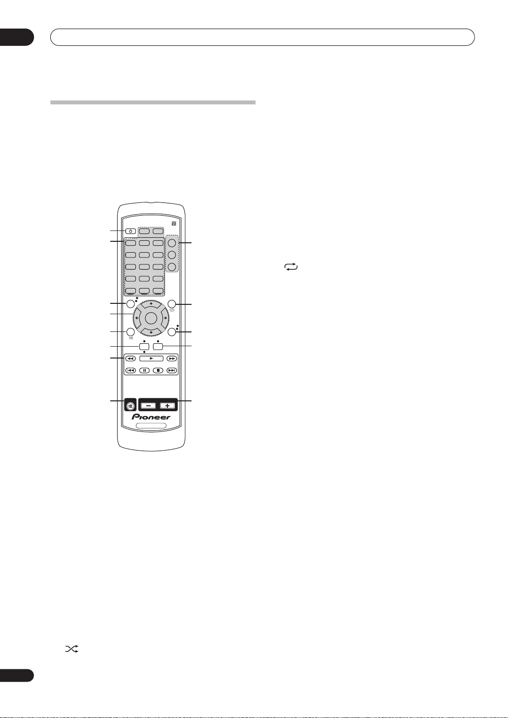
04
Controls and displays
Sub remote control unit
VSX-84TXSi only
The second remote control supplied with this receiver is
for use with the multi-room listening feature, as
explained on page 57. Note that you must connect a
separate IR receiver as explained in
receiver
on page 59 for remote control in your sub
room(s).
RECEIVER
DVD
DVR1 DVR2
VIDEO2
MULTI IN
iPod
TOP MENU
ST
CATEGORY
HDMI
TV
CD
PHONO
TUNER
ENTER
TUNE
DISP
1
2
3
4
5
6
7
MUTE VOLUME
8
RECEIVER
i.LINK
VIDEO1
CD-R
CLASS
PHOTO
MAIN
SAT
ROOM2
ROOM3
USB
XM
T.EDITTUNE
ST
RETURN
BAND
Connecting an IR
9
10
11
12
13
6
DISP
Switches between named station presets and radio
frequencies (page 33).
7 Component control buttons
These are used to control a component after you have
selected it using the input source buttons.
8 MUTE
Mutes the sound or restores the sound if it has been
muted (adjusting the volume also restores the sound).
9 Multi-room select
Selects the room you want to control using this remote.
10
T.EDIT
Use with
recall
/
(page 33).
to memorize and name stations for
Selects the repeat mode of an iPod (page 47).
11 RETURN
Press to confirm and exit the current menu screen.
BAND
Switches between AM and FM radio bands (page 32).
12
CLASS
Switches between the three banks (classes) of radio
station presets (page 33).
PHOTO
Press to view iPod photos and video content
(page 48)
13 VOLUME +/–
Use to set the listening volume.
.
26
En
1 RECEIVER
This switches between standby and on for this receiver.
2 Input source buttons
Press to select control of other components (see
Controlling the rest of your system
3
TOP MENU
on page 71).
Displays the top menu of an iPod and XM Radio.
4
(TUNE/ST) /
ENTER
Use the arrow buttons when setting up your surround
sound system (see page 34) and the AV options
(page 66). Also used to control iPod and XM Radio
menus. Use the
frequencies and use
TUNE
/
buttons to find radio
ST
/
to find preset stations
(page 33).
5
CATEGORY
Selects XM Radio genre search (page 49).
Selects the shuffle mode of an iPod (page 47).
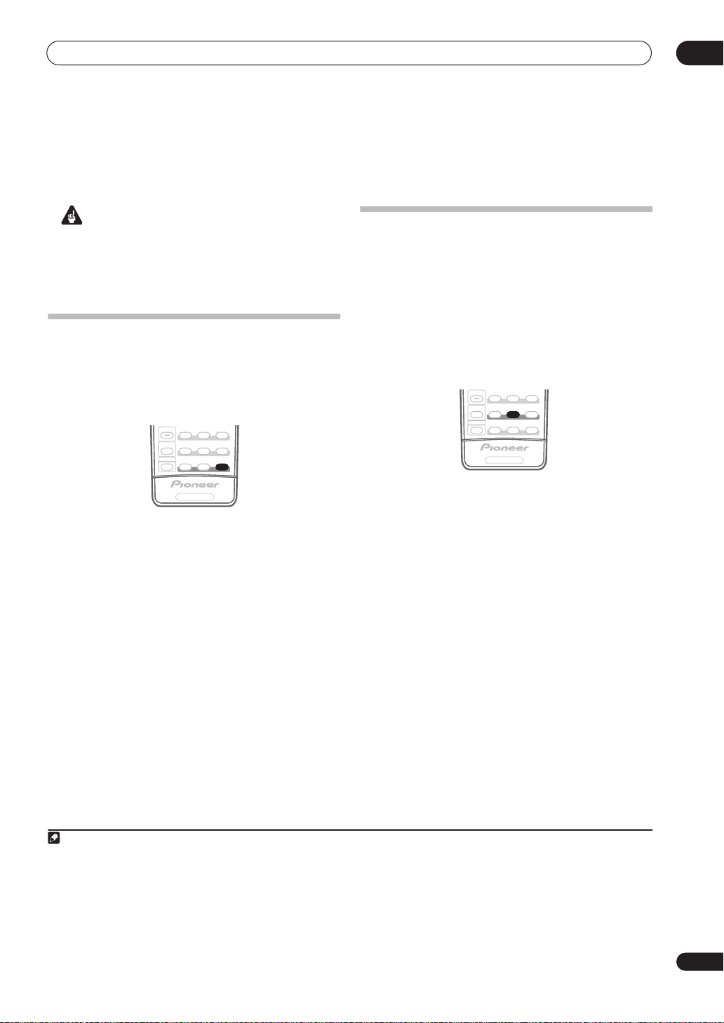
Listening to your system
PHOTO
Chapter 5:
Listening to your system
05
Important
• The listening modes and many features described in
this section may not be available depending on the
current source, settings and status of the receiver.
See
Listening modes with different input signal
formats
on page 86 for more on this.
Auto playback
There are many ways to listen back to sources using this
receiver, but for the simplest, most direct listening option
is the Auto Surround feature. The receiver automatically
detects what kind of source you’re playing and selects
multichannel or stereo playback as necessary.
SIGNAL SEL
STATUS
SBch
STEREO
ADV. SURR
STANDARD
THX
MULTI OPE
SHIFT
MCACC S.DIRECT
PHASE
RECEIVER
• While listening to a source, press
/
STREAM DIRECT
SURR
AUTO SURROUND
)2 for auto playback of a source.
shows briefly in the display before
S.DIRECT (AUTO
showing the decoding or playback format. Check the
digital format indicators in the front panel display to see
how the source is being processed.
• When listening to XM Radio, the XM HD Surround
feature is selected automatically (see
Surround
on page 49 for more on this).
1
Using XM HD
Listening in surround sound
Using this receiver, you can listen to any source in
surround sound. However, the options available will
depend on your speaker setup and the type of source
you’re listening to.
If you connected surround back speakers, see also
surround back channel processing
on page 30.
Standard surround sound
The following modes provide basic surround sound for
stereo and multichannel sources.
SIGNAL SEL
STATUS
THX
MULTI OPE
SHIFT
PHASE
RECEIVER
• While listening to a source, press
(
STANDARD SURROUND
If necessary, press repeatedly to select a listening mode.
• If the source is Dolby Digital, DTS, or Dolby Surround
encoded, the proper decoding format will
automatically be selected and shows in the display.
With two channel sources
•
2
Pro Logic IIx MOVIE
, you can select from:
especially suited to movie sources
•
2
Pro Logic IIx MUSIC
especially suited to music sources
•2 Pro Logic IIx GAME
3
SBch
STEREO
ADV. SURR
STANDARD
MCACC S.DIRECT
STANDARD
).
– Up to 7.1 channel sound,
– Up to 7.1 channel sound,
5
– Up to 7.1 channel sound,
Using
especially suited to video games
2
•
PRO LOGIC
– 4.1 channel surround sound (sound
from the surround speakers is mono)
•
Neo:6 CINEMA
– 6.1 channel sound, especially
suited to movie sources
Neo:6 MUSIC
•
to music sources
– 6.1 channel sound, especially suited
6
With multichannel sources, if you have connected
surround back speaker(s) and have selected
SBch ON
, you
can select (according to format):
Note
1• Stereo surround (matrix) formats are decoded accordingly using
for more on these decoding formats).
• The Auto Surround feature is canceled if you connect headphones or select the multichannel analog inputs.
2 For more options using this button, see
3 In modes that give 6.1 channel sound, the same signal is heard from both surround back speakers.
4 If surround back channel processing (page 30) is switched
back speaker setting
5 When listening to 2-channel sources in Dolby Pro Logic IIx Music mode, there are three further parameters you can adjust: Center Width, Dimension,
and Panorama. See
6 When listening to 2-channel sources in Neo:6 Music mode, you can also adjust the center image effect (see
on page 36 is set to anything but
Setting the AV options
Using Stream Direct
Normal (SB)
on page 66 to adjust them.
Neo:6 CINEMA
on page 29.
OFF
, or the surround back speakers are set to NO (this happens automatically if the
), 2
Pro Logic IIx
or 2
Pro Logic IIx MOVIE
becomes 2
Pro Logic II
(see
Listening in surround sound
(5.1 channel sound).
Setting the AV options
above
Surround
on page 66).
4
27
En
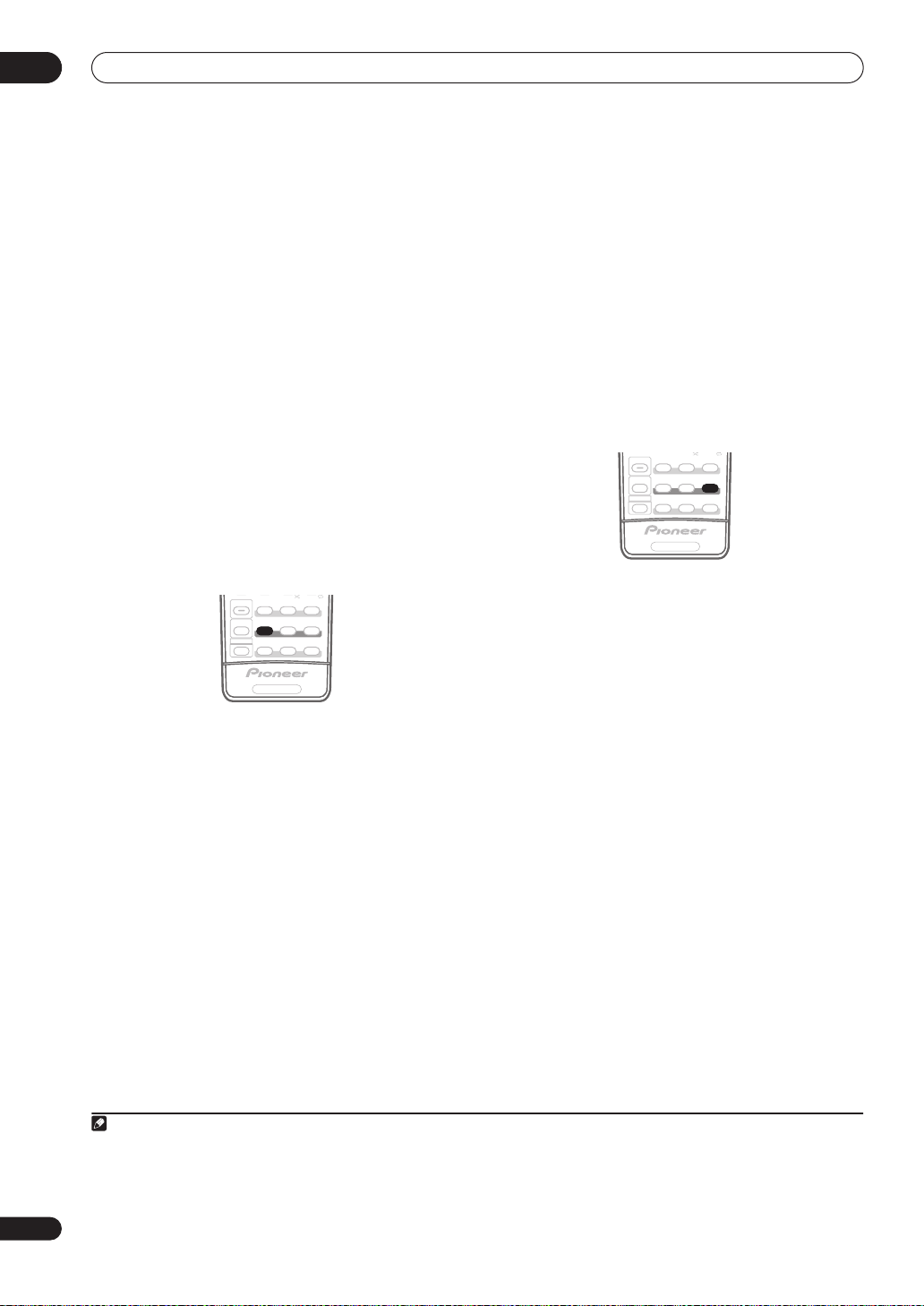
05
PHOTO
PHOTO
Listening to your system
•2
Pro Logic IIx MOVIE
– See above (only available
when you’re using two surround back speakers)
•
2 Pro Logic IIx MUSIC
•
Dolby Digital EX
– See above
– Creates surround back channel
sound for 5.1 channel sources and provides pure
decoding for 6.1 channel sources (like Dolby Digital
Surround EX)
•
DTS-ES
– Allows you to hear 6.1 channel playback
with DTS-ES encoded sources
•
DTS Neo:6
– Allows you to hear 6.1 channel playback
with DTS encoded sources
Using the Home THX modes
THX and Home THX are technical standards created by
THX Ltd. for cinema and home theater sound. Home THX
is designed to make home theater audio sound more like
what you hear in a cinema.
Different THX options will be available depending on the
source and the setting for surround back channel
processing (see
on page 30 for more on this).
• Press
With two channel sources
repeatedly to select a matrix-decoding process for the
THX CINEMA
above for an explanation of each process):
•
2 Pro Logic IIx MOVIE+THX
•2
PRO LOGIC+THX
•
Neo:6 CINEMA+THX
•
THX GAMES MODE
With multichannel sources
repeatedly to select from:
•
THX CINEMA
your home theatre system using all the speakers in
your setup
•
2 Pro Logic IIx MOVIE+THX
movie sources, this allows you to hear 7.1 channel
playback with 5.1 channel sources
•
THX Surround EX
channel playback with 5.1 channel sources
Using surround back channel processing
SIGNAL SEL
STATUS
SBch
STEREO
ADV. SURR
STANDARD
THX
MULTI OPE
SHIFT
MCACC S.DIRECT
PHASE
RECEIVER
THX (HOME THX
mode (see
) to select a listening mode.
, press
THX (HOME THX)
Listening in surround sound
, press
THX (HOME THX)
– Gives you cinema-quality sound from
– Especially suited to
– Allows you to hear 6.1 or 7.1
•
THX Select2 CINEMA
– Allows you to hear 7.1
channel playback with 5.1 channel sources
•
THX MUSICMODE
– Allows you to hear 7.1 channel
playback with 5.1 channel sources
•
THX GAMES MODE
– Allows you to hear 7.1 channel
playback from the output of a video game console
Using the Advanced surround effects
The Advanced surround effects can be used for a variety
of additional surround sound effects. Most Advanced
Surround modes are designed to be used with film
soundtracks, but some modes are also suited for music
sources. Try different settings with various soundtracks
to see which you like.
SIGNAL SEL
STATUS
SBch
STEREO
ADV. SURR
STANDARD
THX
MULTI OPE
SHIFT
MCACC S.DIRECT
PHASE
• Press
ADV.SURR (ADVANCED SURROUND
repeatedly to select a listening mode.
•
ACTION
– Designed for action movies with dynamic
soundtracks
•
SCI-FI
– Designed for science fiction with lots of
special effects
•
DRAMA
1
•
MUSICAL
– Designed for movies with lots of dialog
– Creates a concert hall-type sound for
musicals
•
MONOFILM
– Creates surround sound from mono
soundtracks
•
7-D THEATER
CLASSICAL
•
•
CHAMBER
•
JAZZ
ROCK
•
•
DANCE
7ch STEREO
•
– Gives a large concert hall-type sound
– Creates a space with alot of reverb
– Creates the sound of a small jazz club
– Creates a live concert sound for rock music
– Designed for music with lots of bass
– Allows you to hear stereo sources
from all the speakers in your setup
•
ADV. VIR. SURR.
just the subwoofer and/or the front speakers
• PhonesSurround – When listening through
headphones, you can still get the effect of overall
surround
RECEIVER
2
– Creates an extra wide stereo field
– A virtual surround effect using
)
28
En
Note
1• If you only have one surround back speaker connected, 2 Pro Logic IIx MOVIE+THX, THX Select2 CINEMA, THX MUSICMODE and THX GAMES
MODE are not available.
• You can’t use the THX modes when headphones are connected.
2• Depending on the source and the sound mode you have selected, you may not get sound from the surround back speakers in your setup. For more on
this, refer to Using surround back channel processing on page 30.
• If you press ADV. SURR when the headphones are connected, the PhonesSurround mode will automatically be selected.
 Loading...