

Pioneer VSX-823-K, VSX-1023-K User Manual

Register your product on
http://www.pioneerelectronics.com (US)
http://www.pioneerelectronics.ca (Canada)
•
Protect your new investment
The details of your purchase will be on file for reference in the event of an insurance claim such as loss or theft.
•
Improve product development
Your input helps us continue to design products that meet your needs.
•
Receive a free Pioneer newsletter
Registered customers can opt in to receive a monthly newsletter.
•
Receive free tips, updates and service bulletins on your new product
AV Receiver
VSX-1023
-K
VSX-823
-K
Operating Instructions
IMPORTANT
CAUTION
RISK OF ELECTRIC SHOCK
DO NOT OPEN
The lightning flash with arrowhead symbol,
within an equilateral triangle, is intended to
alert the user to the presence of uninsulated
“dangerous voltage” within the product’s
enclosure that may be of sufficient
magnitude to constitute a risk of electric
shock to persons.
CAUTION:
TO PREVENT THE RISK OF ELECTRIC
SHOCK, DO NOT REMOVE COVER (OR
BACK). NO USER-SERVICEABLE PARTS
INSIDE. REFER SERVICING TO QUALIFIED
SERVICE PERSONNEL.
NOTE:
This equipment has been tested and found to comply with the limits for a Class B digital device, pursuant to Part 15
of the FCC Rules. These limits are designed to provide reasonable protection against harmful interference in a
residential installation. This equipment generates, uses, and can radiate radio frequency energy and, if not installed
and used in accordance with the instructions, may cause harmful interference to radio communications. However,
there is no guarantee that interference will not occur in a particular installation. If this equipment does cause
harmful interference to radio or television reception, which can be determined by turning the equipment off and on,
the user is encouraged to try to correct the interference by one or more of the following measures:
— Reorient or relocate the receiving antenna.
— Increase the separation between the equipment and receiver.
— Connect the equipment into an outlet on a circuit different from that to which the receiver is connected.
— Consult the dealer or an experienced radio/TV technician for help.
Information to User
Alterations or modifications carried out without appropriate authorization may invalidate the user’s right to operate
the equipment.
WARNING
This equipment is not waterproof. To prevent a fire or
shock hazard, do not place any container filled with
WARNING
To prevent a fire hazard, do not place any naked flame
sources (such as a lighted candle) on the equipment.
liquid near this equipment (such as a vase or flower
pot) or expose it to dripping, splashing, rain or
moisture.
D3-4-2-1-3_A1_En
The exclamation point within an equilateral
triangle is intended to alert the user to the
presence of important operating and
maintenance (servicing) instructions in the
literature accompanying the appliance.
D3-4-2-1-1b_A1_En
D8-10-1-2_A1_En
D8-10-2_A1_En
D3-4-2-1-7a_A1_En
VENTILATION CAUTION
When installing this unit, make sure to leave space
around the unit for ventilation to improve heat radiation
(at least 40 cm at top, 20 cm at rear, and 20 cm at each
side).
WARNING
Slots and openings in the cabinet are provided for
ventilation to ensure reliable operation of the product,
and to protect it from overheating. To prevent fire
hazard, the openings should never be blocked or
covered with items (such as newspapers, table-cloths,
curtains) or by operating the equipment on thick carpet
or a bed.
D3-4-2-1-7b*_A1_En
Operating Environment
Operating environment temperature and humidity:
+5 °C to +35 °C (+41 °F to +95 °F); less than 85 %RH
(cooling vents not blocked)
Do not install this unit in a poorly ventilated area, or in
locations exposed to high humidity or direct sunlight (or
strong artificial light)
Caution
To prevent fire hazard, the Class 2 Wiring Cable
should be used for connection with speaker, and
should be routed away from hazards to avoid damage
to the insulation of the cable.
D3-4-2-1-7c*_A1_En
D3-7-13-67*_A1_En
.
2
.
Read these instructions.
Keep these instructions.
Heed all warnings.
Follow all instructions.
Do not use this apparatus near water.
Clean only with dry cloth.
Do not block any ventilation openings. Install in
accordance with the manufacturer’s
instructions.
Do not install near any heat sources such as
radiators, heat registers, stoves, or other
apparatus (including amplifiers) that produce
heat.
Do not defeat the safety purpose of the polarized
or grounding-type plug. A polarized plug has two
blades with one wider than the other. A
grounding type plug has two blades and a third
grounding prong. The wide blade or the third
prong are provided for your safety. If the provided
plug does not fit into your outlet, consult an
electrician for replacement of the obsolete outlet.
Protect the power cord from being walked on or
pinched particularly at plugs, convenience
receptacles, and the point where they exit from
the apparatus.
1)
2)
3)
4)
5)
6)
7)
8)
9)
10)
Only use attachments/accessories specified by
the manufacturer.
Use only with the cart, stand, tripod, bracket, or
table specified by the manufacturer, or sold with
the apparatus. When a cart is used, use caution
when moving the cart/apparatus combination to
avoid injury from tip-over.
Unplug this apparatus during lightning storms
or when unused for long periods of time.
Refer all servicing to qualified service personnel.
Servicing is required when the apparatus has
been damaged in any way, such as power-supply
cord or plug is damaged, liquid has been spilled
or objects have fallen into the apparatus, the
apparatus has been exposed to rain or moisture,
does not operate normally, or has been dropped.
D3-7-13-69_En
11)
12)
13)
14)
CAUTION
The STANDBY/ON switch on this unit will not
completely shut off all power from the AC outlet.
Since the power cord serves as the main disconnect
device for the unit, you will need to unplug it from the
AC outlet to shut down all power. Therefore, make
sure the unit has been installed so that the power
cord can be easily unplugged from the AC outlet in
case of an accident. To avoid fire hazard, the power
cord should also be unplugged from the AC outlet
when left unused for a long period of time (for
example, when on vacation).
D3-4-2-2-2a*_A1_En
These symbols are only valid
in the European Union.
K058c_A1_En
(Symbol examples for batteries)
Pb
This Class B digital apparatus complies with
Canadian ICES-003.
D8-10-1-3_A1_En
CAUTION
This product satisfies FCC regulations when shielded
cables and connectors are used to connect the unit
to other equipment. To prevent electromagnetic
interference with electric appliances such as radios
and televisions, use shielded cables and connectors
for connections.
D8-10-3a_A1_En
IMPORTANT NOTICE
THE MODEL NUMBER AND SERIAL NUMBER OF
THIS EQUIPMENT ARE ON THE REAR OR BOTTOM.
RECORD THESE NUMBERS ON YOUR ENCLOSED
WARRANTY CARD AND KEEP IN A SAFE PLACE
FOR FUTURE REFERENCE.
D36-AP9-1_A1_En
WARNING: Handling the cord on this product or
cords associated with accessories sold with the
product may expose you to chemicals listed on
proposition 65 known to the State of California and
other governmental entities to cause cancer and
birth defect or other reproductive harm.
D36-P5_B1_En
This product is for general household purposes. Any
failure due to use for other than household purposes
(such as long-term use for business purposes in a
restaurant or use in a car or ship) and which requires
repair will be charged for even during the warranty
period.
K041_A1_En
WARNING
Store small parts out of the reach of children and
infants. If accidentally swallowed, contact a doctor
immediately.
D41-6-4_A1_En
3

Contents
Thank you for buying this Pioneer product. Please read
through these operating instructions so you will know how to
operate your model properly.
Before you start
Checking what’s in the box. . . . . . . . . . . . . . . . . . . . . . . . . 6
Installing the receiver . . . . . . . . . . . . . . . . . . . . . . . . . . . . . 6
Flow of settings on the receiver
01 Controls and displays
Front panel . . . . . . . . . . . . . . . . . . . . . . . . . . . . . . . . . . . . . 7
Display . . . . . . . . . . . . . . . . . . . . . . . . . . . . . . . . . . . . . . 8
Remote control. . . . . . . . . . . . . . . . . . . . . . . . . . . . . . . . . . 9
Loading the batteries. . . . . . . . . . . . . . . . . . . . . . . . . . . 10
Operating range of remote control . . . . . . . . . . . . . . . . 10
02 Connecting your equipment
Determining the speakers’ application . . . . . . . . . . . . . . . 11
Some tips for improving sound quality . . . . . . . . . . . . . 12
Connecting the speakers . . . . . . . . . . . . . . . . . . . . . . . . . 12
Connect the surround back or front height speakers
(VSX-1023 only) . . . . . . . . . . . . . . . . . . . . . . . . . . . . . . . 13
Switching the speaker terminal . . . . . . . . . . . . . . . . . . . 15
Making cable connections . . . . . . . . . . . . . . . . . . . . . . . . 15
HDMI cables . . . . . . . . . . . . . . . . . . . . . . . . . . . . . . . . . 15
About HDMI . . . . . . . . . . . . . . . . . . . . . . . . . . . . . . . . . 15
Analog audio cables . . . . . . . . . . . . . . . . . . . . . . . . . . . 16
Digital audio cables. . . . . . . . . . . . . . . . . . . . . . . . . . . . 16
Video cables . . . . . . . . . . . . . . . . . . . . . . . . . . . . . . . . . 16
About video outputs connection. . . . . . . . . . . . . . . . . . . . 16
Connecting a TV and playback components . . . . . . . . . . . 17
Connecting using HDMI . . . . . . . . . . . . . . . . . . . . . . . . 17
Connecting your TV with no HDMI input . . . . . . . . . . . . 18
Connecting optional Bluetooth
Connecting to the network through LAN interface . . . . . . 19
Connecting antennas . . . . . . . . . . . . . . . . . . . . . . . . . . . . 20
Using external antennas . . . . . . . . . . . . . . . . . . . . . . . . 20
Connecting an IR receiver (VSX-1023 only) . . . . . . . . . . . . 20
Connecting an iPod . . . . . . . . . . . . . . . . . . . . . . . . . . . . . 21
Use a dedicated cable to enjoy iPod video . . . . . . . . . . . 21
Connecting a USB device. . . . . . . . . . . . . . . . . . . . . . . . . 21
Connecting an MHL-compatible device . . . . . . . . . . . . . . 22
Connecting an HDMI-equipped component to the front
panel input . . . . . . . . . . . . . . . . . . . . . . . . . . . . . . . . . . . . 22
Plugging in the receiver . . . . . . . . . . . . . . . . . . . . . . . . . . 22
. . . . . . . . . . . . . . . . . . . . . . . . . . . . . 6
. . . . . . . . . . . . . . 6
®
ADAPTER . . . . . . . . . . . 19
03 Basic Setup
Automatically setting up for surround sound (MCACC) . . 23
Other problems when using the Auto MCACC setup. . . 24
04 Basic playback
Playing a source . . . . . . . . . . . . . . . . . . . . . . . . . . . . . . . . 25
Selecting the audio input signal . . . . . . . . . . . . . . . . . . 25
Playing an iPod . . . . . . . . . . . . . . . . . . . . . . . . . . . . . . . . . 27
Playing back files stored on an iPod . . . . . . . . . . . . . . . 28
Basic playback controls. . . . . . . . . . . . . . . . . . . . . . . . . 28
Watching photos and video content . . . . . . . . . . . . . . . 28
Playing a USB device . . . . . . . . . . . . . . . . . . . . . . . . . . . . 28
Playing back audio files stored on a USB memory
device . . . . . . . . . . . . . . . . . . . . . . . . . . . . . . . . . . . . . . 29
Playing back photo files stored on a USB memory
device . . . . . . . . . . . . . . . . . . . . . . . . . . . . . . . . . . . . . . 29
About playable file formats . . . . . . . . . . . . . . . . . . . . . . 29
Playing an MHL-compatible device. . . . . . . . . . . . . . . . . . 30
®
Bluetooth
Music . . . . . . . . . . . . . . . . . . . . . . . . . . . . . . . . . . . . . . . . 31
Listening to the radio . . . . . . . . . . . . . . . . . . . . . . . . . . . . 33
05 Listening to your system
Choosing the listening mode . . . . . . . . . . . . . . . . . . . . . . 34
Using the Sound Retriever . . . . . . . . . . . . . . . . . . . . . . . . 35
Listening with Acoustic Calibration EQ. . . . . . . . . . . . . . . 36
Better sound using Phase Control . . . . . . . . . . . . . . . . . . 36
Using surround back channel processing
(VSX-1023 only) . . . . . . . . . . . . . . . . . . . . . . . . . . . . . . . . . 36
Setting the Up Mix function (VSX-1023 only) . . . . . . . . . . . 36
Setting the Audio options . . . . . . . . . . . . . . . . . . . . . . . . . 37
ADAPTER for Wireless Enjoyment of
Wireless music play. . . . . . . . . . . . . . . . . . . . . . . . . . . . 31
Pairing the Bluetooth ADAPTER and Bluetooth wireless
technology device . . . . . . . . . . . . . . . . . . . . . . . . . . . . . 31
Listening to Music Contents of Bluetooth wireless
technology device with Your System . . . . . . . . . . . . . . . 32
AIR JAM . . . . . . . . . . . . . . . . . . . . . . . . . . . . . . . . . . . . 32
Improving FM sound . . . . . . . . . . . . . . . . . . . . . . . . . . . 33
Saving station presets . . . . . . . . . . . . . . . . . . . . . . . . . . 33
Listening to station presets . . . . . . . . . . . . . . . . . . . . . . 33
Naming preset stations . . . . . . . . . . . . . . . . . . . . . . . . . 33
Auto playback . . . . . . . . . . . . . . . . . . . . . . . . . . . . . . . . 34
Listening in surround sound . . . . . . . . . . . . . . . . . . . . . 34
Using the Advanced surround . . . . . . . . . . . . . . . . . . . 35
Using Stream Direct . . . . . . . . . . . . . . . . . . . . . . . . . . . 35
06 Playback with NETWORK features
Introduction . . . . . . . . . . . . . . . . . . . . . . . . . . . . . . . . . . . 39
About playable DLNA network devices. . . . . . . . . . . . . . 39
Using AirPlay on iPod touch, iPhone, iPad, and
iTunes . . . . . . . . . . . . . . . . . . . . . . . . . . . . . . . . . . . . . . 39
About the DHCP server function . . . . . . . . . . . . . . . . . . 39
Authorizing this receiver . . . . . . . . . . . . . . . . . . . . . . . . 39
About HTC Connect . . . . . . . . . . . . . . . . . . . . . . . . . . . . 40
Playback with Network functions . . . . . . . . . . . . . . . . . . . 40
Basic playback controls . . . . . . . . . . . . . . . . . . . . . . . . . 40
Listening to Internet radio stations. . . . . . . . . . . . . . . . . 41
Listening to Pandora Internet Radio. . . . . . . . . . . . . . . . 41
Playing back audio files stored on components on the
network . . . . . . . . . . . . . . . . . . . . . . . . . . . . . . . . . . . . . 42
Playing back your favorite songs . . . . . . . . . . . . . . . . . . 42
The Network Setup menu . . . . . . . . . . . . . . . . . . . . . . . . . 42
Network Configuration . . . . . . . . . . . . . . . . . . . . . . . . . . 42
Language. . . . . . . . . . . . . . . . . . . . . . . . . . . . . . . . . . . . 43
Firmware Update . . . . . . . . . . . . . . . . . . . . . . . . . . . . . . 43
Network setting using Safari browser . . . . . . . . . . . . . . 44
Friendly Name setting using Safari browser. . . . . . . . . . 44
Firmware update using Safari browser. . . . . . . . . . . . . . 44
Factory Reset . . . . . . . . . . . . . . . . . . . . . . . . . . . . . . . . . 45
System Information . . . . . . . . . . . . . . . . . . . . . . . . . . . . 45
About network playback . . . . . . . . . . . . . . . . . . . . . . . . . . 46
Content playable over a network . . . . . . . . . . . . . . . . . . 46
About playback behavior over a network . . . . . . . . . . . . 47
Glossary . . . . . . . . . . . . . . . . . . . . . . . . . . . . . . . . . . . . . . 47
About playable file formats . . . . . . . . . . . . . . . . . . . . . . . . 48
07 Home Menu
Using the Home Menu . . . . . . . . . . . . . . . . . . . . . . . . . . . 49
Manual speaker setup. . . . . . . . . . . . . . . . . . . . . . . . . . . . 49
Speaker Setting . . . . . . . . . . . . . . . . . . . . . . . . . . . . . . . 49
X.Over . . . . . . . . . . . . . . . . . . . . . . . . . . . . . . . . . . . . . . 50
Channel Level . . . . . . . . . . . . . . . . . . . . . . . . . . . . . . . . 50
Speaker Distance. . . . . . . . . . . . . . . . . . . . . . . . . . . . . . 51
The Input Assign menu . . . . . . . . . . . . . . . . . . . . . . . . . . . 51
Analog Input . . . . . . . . . . . . . . . . . . . . . . . . . . . . . . . . . 51
Component Input (VSX-1023 only) . . . . . . . . . . . . . . . . . 51
The Auto Power Down menu. . . . . . . . . . . . . . . . . . . . . . . 52
The Network Standby menu . . . . . . . . . . . . . . . . . . . . . . . 52
The MHL Setup menu . . . . . . . . . . . . . . . . . . . . . . . . . . . . 52
The Speaker System setting (VSX-1023 only) . . . . . . . . . . . 52
The OSD Setup menu . . . . . . . . . . . . . . . . . . . . . . . . . . . . 53
4

08 Using the MULTI-ZONE feature (VSX-1023 only)
MULTI-ZONE listening . . . . . . . . . . . . . . . . . . . . . . . . . . . 54
Making MULTI-ZONE connections . . . . . . . . . . . . . . . . 54
Using the MULTI-ZONE controls . . . . . . . . . . . . . . . . . . 54
09 Control with HDMI function
Making Control with HDMI connections. . . . . . . . . . . . . . 55
HDMI Setup . . . . . . . . . . . . . . . . . . . . . . . . . . . . . . . . . . . 55
Before using synchronization . . . . . . . . . . . . . . . . . . . . . . 56
About synchronized operations . . . . . . . . . . . . . . . . . . . . 56
Cautions on the Control with HDMI function . . . . . . . . . . 56
10 Controlling the rest of your system
Setting the remote to control other components . . . . . . . 57
Selecting preset codes directly. . . . . . . . . . . . . . . . . . . . . 57
Clearing all the remote control settings . . . . . . . . . . . . . . 57
Controls for TVs . . . . . . . . . . . . . . . . . . . . . . . . . . . . . . . . 58
Controls for other components. . . . . . . . . . . . . . . . . . . . . 58
Preset Code List . . . . . . . . . . . . . . . . . . . . . . . . . . . . . . . . 58
11 Additional information
Troubleshooting . . . . . . . . . . . . . . . . . . . . . . . . . . . . . . . . 62
General . . . . . . . . . . . . . . . . . . . . . . . . . . . . . . . . . . . . . 62
NETWORK feature. . . . . . . . . . . . . . . . . . . . . . . . . . . . . 63
HDMI . . . . . . . . . . . . . . . . . . . . . . . . . . . . . . . . . . . . . . 64
Important information regarding the HDMI
connection . . . . . . . . . . . . . . . . . . . . . . . . . . . . . . . . . . 64
Windows 7 . . . . . . . . . . . . . . . . . . . . . . . . . . . . . . . . . . . . 64
MHL . . . . . . . . . . . . . . . . . . . . . . . . . . . . . . . . . . . . . . . . . 64
About iPod/iPhone/iPad. . . . . . . . . . . . . . . . . . . . . . . . . . 65
Apple Lossless Audio Codec . . . . . . . . . . . . . . . . . . . . . . 65
About FLAC . . . . . . . . . . . . . . . . . . . . . . . . . . . . . . . . . . . 65
About messages displayed when using network
functions . . . . . . . . . . . . . . . . . . . . . . . . . . . . . . . . . . . . . 65
Resetting the main unit . . . . . . . . . . . . . . . . . . . . . . . . . . 66
Cleaning the unit . . . . . . . . . . . . . . . . . . . . . . . . . . . . . . . 66
Specifications. . . . . . . . . . . . . . . . . . . . . . . . . . . . . . . . . . 67
Contents
5
Before you start
Flow of settings on the receiver
Checking what’s in the box
Please check that you’ve received the following supplied
accessories:
•
Setup microphone
•
Remote control
•
AAA size IEC R03 dry cell batteries (to confirm system
operation) x2
•
AM loop antenna
•
FM wire antenna
•
Warranty card
•
Quick start guide
•
Safety Brochure
•
SPEAKER CAUTION Sheet (English only)
•
These operating instructions (CD-ROM)
Installing the receiver
•
When installing this unit, make sure to put it on a level and
stable surface.
Don’t install it on the following places:
– on a color TV (the screen may distort)
– near a cassette deck (or close to a device that gives off a
magnetic field). This may interfere with the sound.
– in direct sunlight
– in damp or wet areas
– in extremely hot or cold areas
– in places where there is vibration or other movement
– in places that are very dusty
– in places that have hot fumes or oils (such as a kitchen)
The unit is a full-fledged AV receiver equipped with an
abundance of functions and terminals. It can be used easily
after following the procedure below to make the connections
and settings.
The colors of the steps indicate the following:
Required setting item
Setting to be made as necessary
- - - - - - - - - - - - - - - - - - - - - - - - - - - - - - - - - - - - - - - - - -
Connecting the speakers
1
Where you place the speakers will have a big effect on
the sound.
•
Determining the speakers’ application (page 11)
•
Connecting the speakers (page 12)
•
Switching the speaker terminal (page 15)
Connecting the components
2
For surround sound, you’ll want to hook up using a
digital connection from the Blu-ray Disc/DVD player to
the receiver.
•
About video outputs connection (page 16)
•
Connecting a TV and playback components (page 17)
•
Connecting antennas (page 20)
•
Plugging in the receiver (page 22)
Power On
3
Make sure you’ve set the video input on your TV to this
receiver. Check the manual that came with the TV if you
don’t know how to do this.
The Speaker System setting (VSX-1023 only) (page 52)
4
(Specify either using the surround back front height
Speaker Bi-amp ZONE 2 speaker.)
The Input Assign menu (page 51
(When using connections other than the recommended
connections.)
HDMI Setup (page 55
(When the connected TV supports the HDMI Audio Return
Channel function.)
Use the on-screen automatic MCACC setup to set up
5
your system
•
Automatically setting up for surround sound (MCACC)
(page 23
)
Basic playback (page 25)
6
•
Selecting the audio input signal (page 25)
•
Playing an iPod (page 27)
•
Playing a USB device (page 28)
•
Choosing the listening mode (page 34)
Adjusting the sound as desired
7
•
Using the Sound Retriever (page 35)
•
Better sound using Phase Control (page 36)
•
Listening with Acoustic Calibration EQ (page 36)
•
Using surround back channel processing (VSX-1023
only) (page 36
•
Setting the Up Mix function (VSX-1023 only) (page 36)
•
Setting the Audio options (page 37)
•
Manual speaker setup (page 49)
Making maximum use of the remote control
8
•
Setting the remote to control other components
(page 57
)
)
)
)
4
7
62
6
Chapter
19 20 21 23 24 21
27 28 29 30 30 3231
25
26
22
VSX-1023
1
1
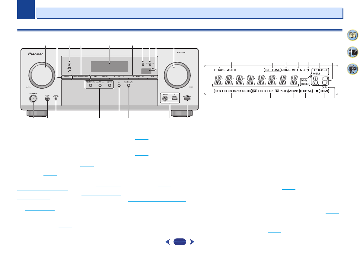
Controls and displays
Front panel
321 8 1049
11
12 1514 17 1813
1
INPUT SELECTOR
Selects an input source (page 25).
2
SPEAKERS
See Switching the speaker terminal on page 15.
The Speaker System setting may or may not be displayed,
depending on the input source you have selected.
3
MCACC indicator
Lights when Acoustic Calibration EQ (page 36) is on (Acoustic
Calibration EQ is automatically set to on after the Auto
MCACC setup (page 23
4
ZONE controls (VSX-1023 only)
If you’ve made MULTI-ZONE connections (see Making MULTI-
ZONE connections on page 54) use these controls to control
the sub zone from the main zone (see Using the MULTI-ZONE
controls on page 54).
5
Character display
See Display on page 8.
6
Tuner control buttons
BAND
– Switches between AM, FM ST (stereo) and FM
MONO radio bands (page 33
dial
)).
).
56
7
16
TUNER EDIT
ENTER
to memorize and name stations for recall
(page 33
).
TUNE
/
PRESET
/
(page 33
).
7
HDMI indicator
Blinks when connecting an HDMI-equipped component;
lights when the component is connected (page 17
8
iPod iPhone iPad indicator
Lights when an iPod/iPhone/iPad is connected and
input is selected (page 27
9
Remote sensor
Receives the signals from the remote control (see Operating
range of remote control on page 10).
10
MASTER VOLUME
11
STANDBY/ON
– Use with
– Used to find radio frequencies (page 33).
TUNE
/, PRESET
– Use to select preset radio stations
).
dial
/
).
iPod/USB
and
7
12
PHONES jack
Use to connect headphones. When the headphones are
connected, there is no sound output from the speakers. The
listening mode when the sound is heard from the headphone
can be selected only from PHONES SURR, STEREO or
STEREO ALC mode (S.R AIR mode can be also selected with
ADAPTER input).
13
MCACC SETUP MIC jack
Use to connect a microphone when performing Auto MCACC
setup (page 23
14
Listening mode buttons
AUTO SURROUND/STREAM DIRECT
Auto surround mode (page 34
playback (page 35
ALC/STANDARD SURR
standard decoding and to switch between the modes of
2 Pro Logic II, 2 Pro Logic IIx, 2 Pro Logic IIz and
NEO:6, and the Auto level control stereo mode (page 34
ALC/STANDARD SURR
standard decoding and to switch between the modes of
2 Pro Logic II and NEO:6, and the Auto level control
stereo mode (page 34
).
– Switches between
).
) and Stream Direct
(VSX-1023 only) – Press for
(VSX-823 only) – Press for
).
4
7
62
).

1
1
Controls and displays
ADVANCED SURROUND
surround modes (page 35
15
ECO
Switches between ECO Mode 1/ECO Mode 2. When ECO
Mode is turned ON, the display will go dark (page 35
16
iPod iPhone iPad DIRECT CONTROL
Change the receiver’s input to the iPod and enable iPod
operations on the iPod (page 29
17
iPod/iPhone/iPad terminals
Use to connect your Apple iPod/iPhone/iPad or USB mass
storage device as an audio source (page 21
18
HDMI input/MHL connector
Use for connection to a compatible HDMI device (Video
camera, etc.) (page 22
can also be connected here using a MHL cable (sold
separately) (page 22
– Switches between the various
).
).
).
). An MHL-compatible mobile device
).
).
Display
19
PHASE
Lights when the Phase Control is switched on (page 36).
20
AUTO
Lights when the Auto Surround feature is switched on
(page 34
).
21
Tuner indicators
ST – Lights when a stereo FM broadcast is being received
in auto stereo mode (page 33
TUNE – Lights when a normal broadcast channel.
PRESET – Shows when a preset radio station is registered
or called.
MEM – Blinks when a radio station is registered.
kHz/MHz – Lights when the character display is showing
the currently received AM/FM broadcast frequency.
22
ZONE (VSX-1023 only)
Lights when the MULTI-ZONE feature is active (page 54).
23
Speaker indicators
Shows if the speaker system is on or not (page 15).
24
Sleep timer indicator
Lights when the receiver is in sleep mode (page 9).
).
25
PRESET information or input signal indicator
Shows the preset number of the tuner or the input signal type,
etc.
26
Character display
Displays various system information.
27
DTS indicators
DTS – Lights when a source with DTS encoded audio
signals is detected.
HD – Lights when a source with DTS-EXPRESS or DTS-HD
encoded audio signals is detected.
ES – Lights to indicate DTS-ES decoding.
96/24 – Lights when a source with DTS 96/24 encoded
audio signals is detected.
NEO:6 – When one of the NEO:6 modes of the receiver is
on, this lights to indicate NEO:6 processing (page 34
28
Dolby Digital indicators
2 D – Lights when a Dolby Digital encoded signal is
detected.
2 D+ – Lights when a source with Dolby Digital Plus
encoded audio signals is detected.
2HD – Lights when a source with Dolby TrueHD encoded
audio signals is detected.
EX (VSX-1023 only) – Lights to indicate Dolby Digital EX
decoding.
2PLII(x) (VSX-1023 only) – Lights to indicate 2 Pro Logic
II decoding. Light will go off during 2 Pro Logic IIz
decoding (see Listening in surround sound
more on this).
2PLII (VSX-823 only) – Lights to indicate 2 Pro Logic II
decoding. (see Listening in surround sound
more on this).
29
ADV.S.
Lights when one of the Advanced Surround modes has been
selected (see Using the Advanced surround
more on this).
30
SIGNAL SELECT indicators
DIGITAL – Lights when a digital audio signal is selected.
Blinks when a digital audio signal is selected and selected
audio input is not provided.
on page 35 for
).
on page 34 for
on page 34 for
HDMI – Lights when an HDMI signal is selected. Blinks
when an HDMI signal is selected and selected HDMI input
is not provided.
31
Up Mix indicator (VSX-1023 only)
Lights when the Up Mix function is set to ON (page 36).
32
DIR.
Lights when the DIRECT or PURE DIRECT mode is switched
on (page 35
).
4
7
62
8
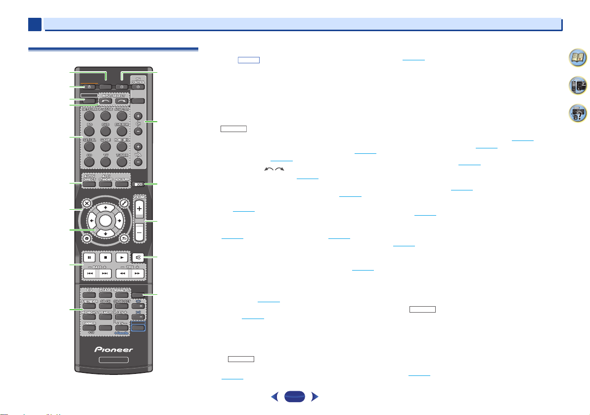
1
SHIFT
RECEIVER
RECEIVER
1
Remote control
1
RECEIVER
2
RECEIVER
3
4
5
6
AUDIO
PARAMETER
TOP
MENU
7
8
HOME
MENU
PTY
iPod CTRL
9
10
Controls and displays
•
The following buttons are not used with this receiver:
-
PTY
,
1
SLEEP
SOURCE
INPUT
12
13
TOOLS
MENU
N
U
E
T
11
ENTER
T
E
U
N
2
5
8
0
RECEIVER
RETURN
3
6
9
ENTER
P
R
E
S
E
T
BAND
MUTE
DISP
CH
CH
SHIFT
14
15
16
T
E
S
E
R
P
1
4
7
CLR
SLEEP
Press to change the amount of time before the receiver
switches into standby (30 min – 60 min – 90 min – Off). You
can check the remaining sleep time at any time by pressing
SLEEP
once.
2
RECEIVER
Switches the receiver between standby and on.
3
Switches the remote to control the receiver (used to select the
white commands above the number buttons (
etc)). Also use this button to set up surround sound (page 49
or Audio parameters (page 37
4
INPUT SELECT
Use to select the input source (page 25).
5
Input function buttons
Use to select the input source to this receiver (page 25). This
will enable you to control other components with the remote
control (page 57
6
Listening mode buttons
AUTO/DIRECT
(page 34
ALC/STANDARD SURR
standard decoding and to switch between the modes of
2 Pro Logic II, 2 Pro Logic IIx, 2 Pro Logic IIz and
NEO:6, and the Auto level control stereo mode (page 34
ALC/STANDARD SURR
standard decoding and to switch between the modes of
2 Pro Logic II and NEO:6, and the Auto level control
stereo mode (page 34
ADV SURR
modes (page 35
7
Receiver and component control buttons
The following button controls can be accessed after you have
selected the corresponding input function button (
etc.).
).
– Switches between Auto surround mode
) and Stream Direct playback (page 35).
– Switches between the various surround
).
(VSX-1023 only) – Press for
(VSX-823 only) – Press for
).
).
MIDNIGHT
BD, DVD
,
Press first to access:
AUDIO PARAMETER
(page 37
).
– Use to access the Audio options
HOME MENU
(page 49
RETURN
BD, DVD
Press
TOP MENU
Disc/DVD.
HOME MENU
RETURN
MENU
TUNER
Press
TOOLS
used to change the name (page 33
)
BAND
MONO radio bands (page 33
iPod/USB
Press
iPod CTRL
receiver controls (page 28
8
/// (TUNE
Use the arrow buttons when setting up your surround sound
system (page 49
menus/options.
Use
TUNE
PRESET
(page 33
9
Component control buttons
The main buttons (, , etc.) are used to control a component
).
after you have selected it using the input function buttons.
The controls above these buttons can be accessed after you
have selected the corresponding input function button (
DVD
and CD). These buttons also function as described
below.
RECEIVER
Press first to access:
BASS +/–, TRE +/–
• These controls are disabled when the listening mode is
,
set to DIRECT or PURE DIRECT.
• When the front speaker is set at SMALL in the Speaker
Setting (or automatically via the Auto MCACC setup)
and the X.Over is set above 100 Hz, the subwoofer
channel level will be adjusted by pressing
(page 50
– Press to access the Home Menu
).
– Confirm and exit the current menu screen.
or
DVR/BDR
first to access:
– Displays the disc ‘top’ menu of a Blu-ray
– Displays the HOME MENU screen.
– Confirm and exit the current menu screen.
– Display s the TOOLS menu of Blu-ray Disc player.
first to access:
– Memorizes stations for recall (page 33), also
– Switches between AM, FM ST (stereo) and FM
).
).
first to access:
– Switches between the iPod controls and the
).
/, PRESET
/
),
ENTER
). Also used to control Blu-ray Disc/DVD
/
can be used to find radio frequencies and
/
can be used to select preset radio stations
).
– Use to adjust Bass or Treble.
).
BASS +/–
BD
4
7
62
,
9
1
CAUTION
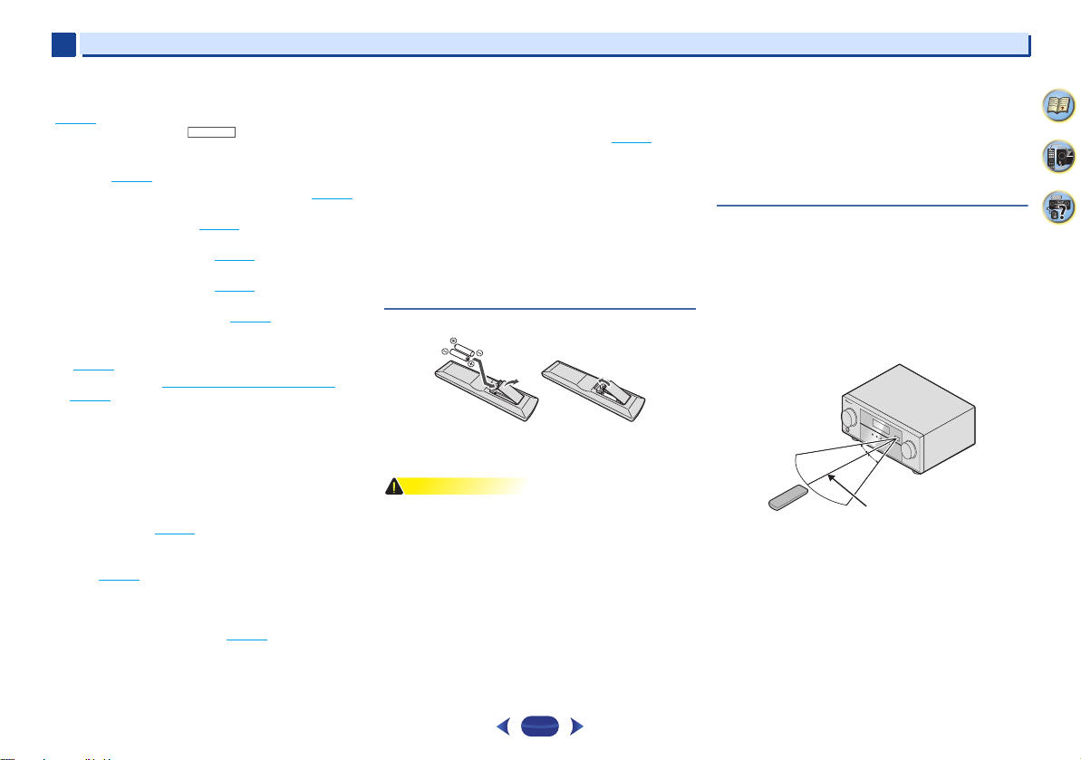
RECEIVER
30°
7 m (23 ft.)
30°
1
10
Number buttons and other component controls
Use the number buttons to directly select a radio frequency
(page 33
) or the tracks on a CD, etc. There are other buttons
that can be accessed after is pressed. (For example
MIDNIGHT
11
Press to turn on/off other components connected to the
receiver (page 57
12
These buttons are dedicated to control the TV assigned to the
TV
system assign it to the
, etc.)
EQ
– Press to switch on/off Acoustic Calibration EQ
setting (page 36
PHASE
SIGNAL SEL
component to play back (page 25
S.RETRIEVER
compressed audio sources (page 35
SB CH
the surround back channel (page 36
CH SELECT
use
LEV +/–
LEV +/–
MIDNIGHT
(page 37
SPEAKERS
page 15.
DIMMER
can be controlled in four steps.
During ECO mode, the brightness switches between 2
levels. If the dimmest level is selected, DIMMER will be
shown on the display. (Mode other than ECO: 4 levels, ECO
mode: 2 levels)
+Favorite
stopped. The selected song is then registered in the
Favorites folder (page 42
SOURCE
TV CONTROL buttons
button. Thus if you only have one TV to hook up to this
– Use to turn on/off the power of the TV.
INPUT
CH +/–
).
– Press to switch on/off Phase Control (page 36).
– Press to select the audio input signal of the
– Press to restore CD quality sound to
(VSX-1023 only) – Press to select ON, AUTO or OFF
– Press repeatedly to select a channel, then
to adjust the level (page 50).
– Use to adjust the channel level.
– Switches to Midnight or Loudness listening
).
– See Switching the speaker terminal on
– Dims or brightens the display. The brightness
– Press while a song is being played back or
).
TV
button (page 58).
– Use to select the TV input signal.
– Use to select channels.
).
).
).
).
VOL +/–
– Use to adjust the volume on your TV.
13
ECO
Switches between ECO Mode 1/ECO Mode 2. When ECO
Mode is turned ON, the display will go dark (page 35
14
VOLUME +/–
Use to set the listening volume.
15
MUTE
Mutes/unmutes the sound.
16
DISP
Switches the display of this unit. The listening mode, sound
volume, Speaker System (VSX-1023) setting or input name can
be checked by selecting an input source.
•
The Speaker System setting may or may not be displayed,
depending on the input source you have selected.
).
Loading the batteries
The batteries included with the unit are to check initial
operations; they may not last over a long period. We
recommend using alkaline batteries that have a longer life.
•
Incorrect use of batteries may result in such hazards as
leakage and bursting. Observe the following precautions:
-
Never use new and old batteries together.
-
Insert the plus and minus sides of the batteries properly
according to the marks in the battery case.
-
Batteries with the same shape may have different
voltages. Do not use different batteries together.
-
When disposing of used batteries, please comply with
governmental regulations or environmental public
institution’s rules that apply in your country/area.
Controls and displays
-
Do not use or store batteries in direct sunlight or other
excessively hot place, such as inside a car or near a
heater. This can cause batteries to leak, overheat,
explode or catch fire. It can also reduce the life or
performance of batteries.
-
When inserting the batteries, make sure not to damage
the springs on the battery’s (–) terminals. This can cause
batteries to leak or overheat.
Operating range of remote control
The remote control may not work properly if:
•
There are obstacles between the remote control and the
receiver’s remote sensor.
•
Direct sunlight or fluorescent light is shining onto the
remote sensor.
•
The receiver is located near a device that is emitting
infrared rays.
•
The receiver is operated simultaneously with another
infrared remote control unit.
4
7
62
10
Chapter
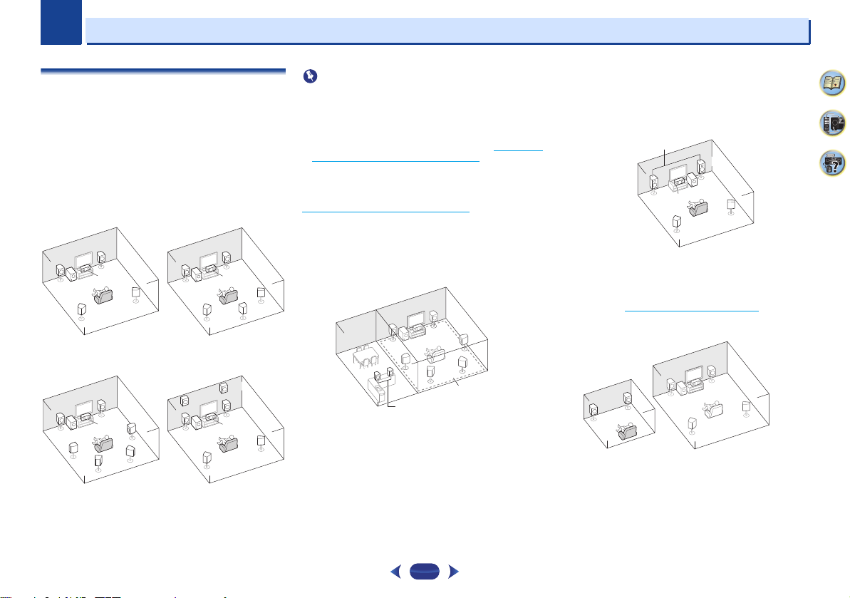
Important
5.1 channel surround
system:
6.1 channel surround
(Surround back) system (VSX1023 only):
C
SL
L
FHL
FHR
SW
R
SR
SL
L
SW
C
R
SR
SBL
SBR
7.1 channel surround
(Surround back) system
(VSX-1023 only):
7.1 channel surround (Front
height) system (VSX-1023
only):
L
R
Main zone
Speaker B
SL
L
R
SR
SW
C
Front Bi-Amp
Main zone
Sub zone
2
2
Connecting your equipment
Determining the speakers’ application
By connecting the left and right front speakers (L/R), the
center speaker (C), the left and right surround speakers (SL/
SR), the left and right surround back speakers (SBL/SBR) (or
the left and right front height speakers (FHL/FHR)), and the
subwoofer (SW), a surround sound system up to 7.1 channel
can be enjoyed.
The 5.1 channel surround system is the most commonly-used
in home theaters. To achieve the best possible surround
sound, install your speakers as shown below.
RR
L
SW
SL
C
SR
L
SW
Bi-amping connection
VSX-1023 only
•
Both the surround back speakers and the front height
speakers can be connected at the same time. In this case,
sound will be output from either the front height speaker or
the surround back speaker depending on which one was
selected in the Speaker System setting (see The Speaker
System setting (VSX-1023 only) on page 52).
Speaker B connection
You can use the speakers connected to the B speaker
terminals to listen to stereo playback in another room. See
Switching the speaker terminal
options with this setup.
•
You will not be able to connect the B speakers if you
connect the front height speakers in the main zone.
Further, if you use the B speakers, a 5.1 ch playback will be
the maximum in the main zone. (No sound is output from
C
SR
SB
SL
the surround back speaker.)
on page 15 for the listening
11
Bi-amping connection of the front speakers for high sound
quality with 5.1-channel surround sound.
•
When using the Front Bi-amping connection, sound will
only be output from the front speakers, the surround
speakers and the subwoofer.
ZONE 2 connection (Multi Zone)
With these connections you can simultaneously enjoy the
surround sound in the main zone with stereo playback on
another component in ZONE 2 (The selection of input devices
is limited). See MULTI-ZONE listening
•
To connect the ZONE 2 speakers, an additional amplifier is
required.
R
L
on page 54.
4
7
62
2
CAUTION
10 mm
(3/8 in.)
12 3
10 mm
(3/8 in.)
2
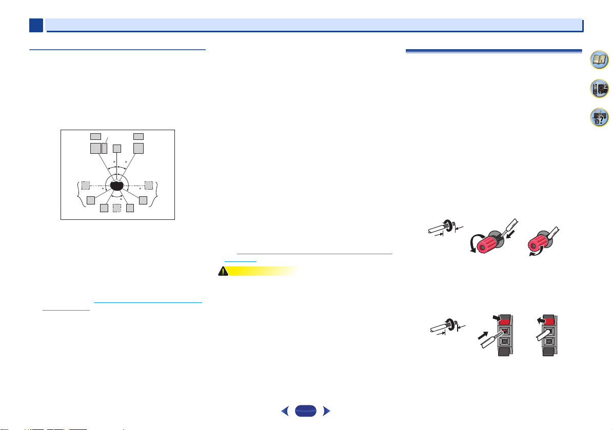
Some tips for improving sound quality
Where you put your speakers in the room has a big effect on
the quality of the sound. The following guidelines should help
you to get the best sound from your system.
•
It is best to angle the speakers towards the listening
position. The angle depends on the size of the room. Use
less of an angle for bigger rooms.
•
Refer to the chart below for placement of speakers you
intend to connect.
SW
FHL
SL
-
Place the surround speakers at 120º from the center. If
you, (1) use the surround back speaker, and, (2) don’t use
the front height speakers, we recommend placing the
surround speaker right beside you.
-
If you intend to connect only one surround back
speakers, place it directly behind you.
-
If the surround speakers cannot be set directly to the side
of the listening position with a 7.1-channel system, the
surround effect can be enhanced by turning off the Up
Mix function (see Setting the Up Mix function (VSX-1023
only) on page 36).
•
For the best stereo effect, place the front speakers 2 m to
3 m apart, at equal distance from the TV.
•
If you’re using a center speaker, place the front speakers at
a wider angle. If not, place them at a narrower angle.
•
Place the center speaker above or below the TV so that the
sound of the center channel is localized at the TV screen.
Also, make sure the center speaker does not cross the line
formed by the leading edge of the front left and right
speakers.
C
L
30 30
120 120
60
SBL
SB
SBR
FHR
R
Connecting your equipment
•
Surround and surround back speakers should be
positioned 60 cm to 90 cm higher than your ears and titled
slight downward. Make sure the speakers don’t face each
other. For DVD-Audio, the speakers should be more directly
behind the listener than for home theater playback.
•
Try not to place the surround speakers farther away from
the listening position than the front and center speakers.
Doing so can weaken the surround sound effect.
•
Place the left and right front height speakers at least one
meter directly above the left and right front speakers.
•
If you’re going to place speakers around your CRT TV, use
shielded speakers or place the speakers at a sufficient
distance from your CRT TV.
•
The subwoofer can be placed on the floor. Ideally, the other
speakers should be at about ear-level when you’re listening
to them. Putting the speakers on the floor (except the
subwoofer), or mounting them very high on a wall is not
recommended.
•
SR
When not connecting a subwoofer, connect speakers with
low frequency reproduction capabilities to the front
channel. (The subwoofer’s low frequency component is
played from the front speakers, so the speakers could be
damaged.)
•
After connecting, be sure to conduct the Auto MCACC
(speaker environment setting) procedure.
See Automatically setting up for surround sound (MCACC)
on page 23.
•
Make sure that all speakers are securely installed. This not
only improves sound quality, but also reduces the risk of
damage or injury resulting from speakers being knocked
over or falling in the event of external shocks such as
earthquakes.
Connecting the speakers
The receiver will work with just two stereo speakers (the front
speakers in the diagram) but using at least three speakers is
recommended, and a complete setup is best for surround
sound.
Make sure you connect the speaker on the right to the right (R)
terminal and the speaker on the left to the left (L) terminal.
Also make sure the positive and negative (+/–) terminals on
the receiver match those on the speakers.
You can use speakers with a normal impedance between 6
and 16 .
Be sure to complete all connections before connecting this unit
to the AC power source.
Bare wire connections
1
Twist exposed wire strands together.
2
Loosen terminal and insert exposed wire.
3
Tighten terminal.
12 3
Connect the wires to the B-Speakers terminals of the VSX-1023
as shown below:
1
Twist exposed wire strands together.
2
Push open the tabs and insert exposed wire.
3
Release the tabs.
4
7
62
12
2
CAUTION
LINE LEVEL
INPUT
FRONT
R L
SURROUND
R L
FRONT HEIGHT
R L
CENTER
PREOUT
SUBWOOFER
SURROUND BACK
R L
Front height setting
Speaker B setting
Front rightSubwoofer
Center
Front left
Surround
right
Surround
left
Surround back right Surround back left
Front height right
Speaker B – right
Front height left
Speaker B – left
The front height terminals can also be used for Speaker B.
The surround back terminals can also be used for ZONE 2.
5.1 ch surround setting
6.1 ch surround setting
7.1 ch surround setting
ZONE 2 setting
Not connected
Not connected
Surround back
Not connected
ZONE 2 – Right ZONE 2 – Left
2
•
These speaker terminals carry HAZARDOUS LIVE voltage. To prevent the risk of electric
shock when connecting or disconnecting the speaker cables, disconnect the power cord
before touching any uninsulated parts.
•
Make sure that all the bare speaker wire is twisted together and inserted fully into the
speaker terminal. If any of the bare speaker wire touches the back panel it may cause the
power to cut off as a safety measure.
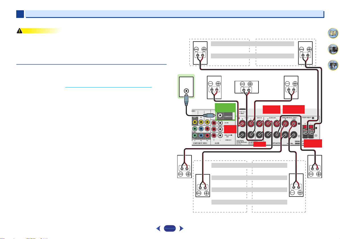
Connect the surround back or front height speakers (VSX-1023 only)
The Speaker System setting must be set if the above connections are performed. Select
Surr.Back if the surround back speaker is connected and Height if the front height speaker is
connected (If neither the surround back speaker nor the front height speaker is connected,
either setting will suffice) (see The Speaker System setting (VSX-1023 only)
•
When using only one surround back speaker, connect it to the SURROUND BACK L (Single)
terminals.
on page 52).
Connecting your equipment
VSX-1023 connection diagram
4
7
62
13
2
Hight
Low
Hight
Low
Center
Surround right
Front right
Front left
Subwoofer
Surround left
Front height left
Front height
right
Center
Surround right
Front right
Front left
Subwoofer
Surround left
2
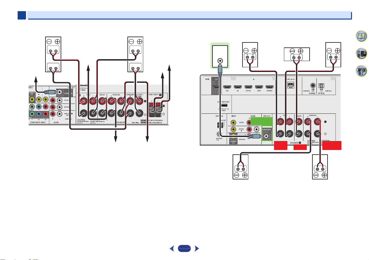
Front Bi-Amp connection (VSX-1023 only) VSX-823 connection diagram
Connecting your equipment
4
LINE LEVEL
INPUT
7
62
PREOUT
SUBWOOFER
FRONT
R L
CENTER
SURROUND
R L
14
2
Note
Important
Note
Note
HDMI
2
Connecting your equipment
Switching the speaker terminal
VSX-1023: When the The Speaker System setting (VSX-1023
only) on page 52 is set to SPB, each press of the speaker
button will switch the speaker used for playback: SP, SPA,
SPB, SPAB.
VSX-823: Each press of the speaker button will switch the
speaker used for playback: SP, SPA.
When the speaker system is set to SP-B: Each press of the
speaker button will switch the speaker used for playback: OFF,
A, B, AB.
When the speaker system is set to anything other than SP-B:
Each press of the speaker button will switch the speaker used
for playback: OFF, A. For more details on the speaker system
please refer to The Speaker System setting (VSX-1023 only)
page 52.
Press repeatedly to choose a speaker terminal option:
•
SPA – Sound is output from the speakers connected to
the A-speaker terminals (multichannel playback is
possible).
•
SPB (VSX-1023 only) – Sound is output from the two
speakers connected to the B-speaker terminals (only stereo
playback is possible).
•
SPAB (VSX-1023 only) – Sound is output from the Aspeaker terminals, the two speakers in the B-speaker
terminals, and the subwoofer. Multichannel sources are
downmixed only when the STEREO or STEREO ALC mode
is selected for stereo output from A- and B-speaker
terminals.
•
SP – No sound is output from the speakers.
•
VSX-1023 only: The subwoofer output depends on the
settings you made in Speaker Setting
if SPB is selected above, no sound is heard from the
subwoofer (the LFE channel is not downmixed).
•
All speaker terminals are switched off (SP) when
headphones are connected. SPB can be selected even
when headphones are connected for VSX-1023.
on page 49. However,
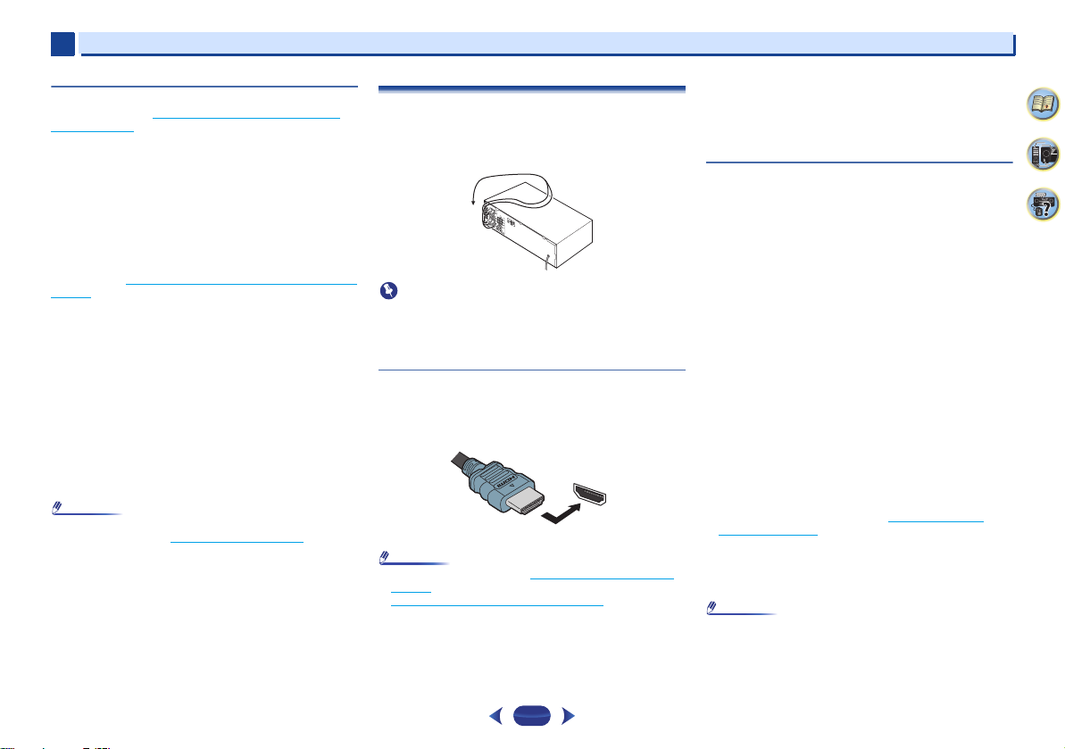
Making cable connections
Make sure not to bend the cables over the top of this unit (as
shown in the illustration). If this happens, the magnetic field
produced by the transformers in this unit may cause a
humming noise from the speakers.
on
•
Before making or changing connections, switch off the
power and disconnect the power cord from the AC outlet.
•
Before unplugging the power cord, switch the power into
standby.
HDMI cables
Both video and sound signals can be transmitted
simultaneously with one cable. If connecting the player and
the TV via this receiver, for both connections, use HDMI
cables.
Be careful to connect the terminal in the proper direction.
•
Set the HDMI parameter in Setting the Audio options on
page 37 to THRU (THROUGH) and set the input signal in
Selecting the audio input signal
want to hear HDMI audio output from your TV (no sound
will be heard from this receiver).
•
If the video signal does not appear on your TV, try adjusting
the resolution settings on your component or display. Note
that some components (such as video game units) have
on page 25 to HDMI, if you
15
resolutions that may not be displayed. In this case, use a
(analog) composite connection.
•
When the video signal from the HDMI is 480i, 480p, 576i or
576p, Multi Ch PCM sound and HD sound cannot be
received.
About HDMI
The HDMI connection transfers uncompressed digital video,
as well as almost every kind of digital audio that the
connected component is compatible with, including DVDVideo, DVD-Audio, SACD, Dolby Digital Plus, Dolby TrueHD,
DTS-HD Master Audio (see below for limitations), Video CD/
Super VCD and CD.
This receiver incorporates High-Definition Multimedia
Interface (HDMI
This receiver supports the functions described below through
HDMI connections.
•
Digital transfer of uncompressed video (contents protected
by HDCP (1080p/24, 1080p/60, etc.))
•
3D signal transfer
•
Deep Color signal transfer
•
x.v.Color signal transfer
•
Audio Return Channel
•
Input of multi-channel linear PCM digital audio signals
(192 kHz or less) for up to 8 channels
•
Input of the following digital audio formats:
– Dolby Digital, Dolby Digital Plus, DTS, High bitrate audio
(Dolby TrueHD, DTS-HD Master Audio), DVD-Audio, CD,
SACD (DSD 2 ch only), Video CD, Super VCD
•
Synchronized operation with components using the
Control with HDMI function (see Control with HDMI
function on page 55)
•
4K signal transfer
– This may not operate properly, depending on the
connected equipment.
– 4K 24p, 4K 25p and 4K 30p signals are supported
•
Use a High Speed HDMI®/™ Cable. If HDMI cable other
than a High Speed HDMI
properly.
•
When an HDMI cable with a built-in equalizer is connected,
it may not operate properly.
®
) technology.
®
/™ Cable is used, it may not work
4
7
62
2
Note
AUDIO
L
R
Red (Right)
White (Left)
Coaxial digital
audio cable
Optical cable
VIDEO
Yellow
Y
P
B
P
R
COMPONENT VIDEO
Green (Y)
Red (PR)
Blue (PB)
VIDEO
VIDEO
IN
IN
HDMI
MONITOR
OUT
HDMI
OUT
Terminal for connection with
source device
Terminal for connection
with TV monitor
Playback component
TV
The OSD will
not appear.
Video signals can be output.
2
•
3D, Deep Color, x.v.Color, 4K signal transfer and Audio
Return Channel are only possible when connected to a
compatible component.
•
HDMI format digital audio transmissions require a longer
time to be recognized. Due to this, interruption in the audio
may occur when switching between audio formats or
beginning playback.
•
Turning on/off the device connected to this unit’s HDMI
OUT terminal during playback, or disconnecting/
connecting the HDMI cable during playback, may cause
noise or interrupted audio.
The terms HDMI and HDMI High-Definition Multimedia
Interface, and the HDMI Logo are trademarks or registered
trademarks of HDMI Licensing, LLC in the United States and
other countries.
“x.v.Color” and are trademarks of Sony
Corporation.
Analog audio cables
Use stereo RCA phono cables to connect analog audio
components. These cables are typically red and white, and
you should connect the red plugs to R (right) terminals and
white plugs to L (left) terminals.
Digital audio cables
Commercially available coaxial digital audio cables or optical
cables should be used to connect digital components to this
receiver.
COAXIAL
IN
OPTICAL
IN
•
When connecting optical cables, be careful when inserting
the plug not to damage the shutter protecting the optical
socket.
•
When storing optical cable, coil loosely. The cable may be
damaged if bent around sharp corners.
•
You can also use a standard RCA video cable for coaxial
digital connections.
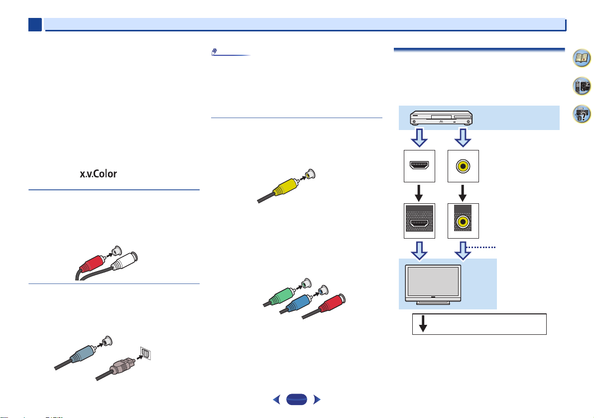
Video cables
Standard RCA video cables
These cables are the most common type of video connection
and are used to connect to the composite video terminals. The
yellow plugs distinguish them from cables for audio.
Component video cables (VSX-1023 only)
Use component video cables to get the best possible color
reproduction of your video source. The color signal of the TV is
divided into the luminance (Y) signal and the color (P
signals and then output. In this way, interference between the
signals is avoided.
B and PR)
Connecting your equipment
About video outputs connection
This receiver is not loaded with a video converter. When you
use HDMI cables for connecting to the input device, the same
cables should be used for connecting to the TV.
The signals input from the analog (composite) video inputs of
this unit will not be output from the HDMI OUT terminal.
4
7
62
16
2
Note
HDMI
OUT
ANALOG
IN1 (CD)
HDMI OUT
HDMI IN
DIGITAL AUDIO OUT
OPTICAL
HDMI OUT
HDMI IN
RL
ANALOG AUDIO OUT
OPTICAL
IN1 (TV)
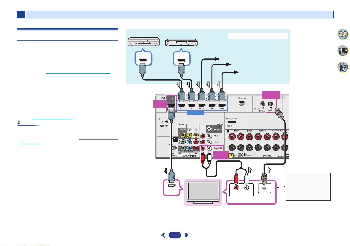
Select one
HDMI/DVI-compatible TV
Set-top box
DVD player
Blu-ray Disc player
Game console
HDMI/DVI-compatible components
If the TV does not support
the HDMI Audio Return
Channel function, this
connection is required to
listen to the TV sound over
the receiver.
DVD recorder, Blu-ray
Disc recorder
VSX-1023
2
Connecting your equipment
Connecting a TV and playback components
Connecting using HDMI
If you have an HDMI or DVI (with HDCP) equipped component
(Blu-ray Disc player, etc.), you can connect it to this receiver
using a commercially available HDMI cable.
If the TV and playback components support the Control with
HDMI feature, the convenient Control with HDMI functions
can be used (see Control with HDMI function
•
The following connection/setting is required to listen to the
sound of the TV over this receiver.
-
-
•
In order to listen to the audio from the TV that is connected
to this receiver using an analog audio cables, set-up for
analog audio input is required (see The Input Assign menu
on page 51).
If the TV does not support the HDMI Audio Return
Channel function, connect the receiver and TV with audio
cables (as shown).
If the TV supports the HDMI Audio Return Channel
function, the sound of the TV can be input to the receiver
via the HDMI terminal, so there is no need to connect an
audio cable. In this case, set ARC at HDMI Setup to ON
(see HDMI Setup
on page 55).
on page 55).
17
4
7
62
2
Important
Note
RECEIVER
ANALOG
IN1 (CD)
VIDEO IN
DIGITAL AUDIO OUT
OPTICAL
RL
ANALOG AUDIO OUT
OPTICAL
IN1 (TV)
DVD IN
SAT/CBL IN
VIDEO OUT
DIGITAL AUDIO OUT
OPTICALCOAXIAL
RL
ANALOG AUDIO OUT
RL
ANALOG AUDIO OUT
VIDEO OUT
COAXIAL
IN1 (CD)
MONITOR
OUT
HDMI
DVD IN
DIGITAL AUDIO OUT
OPTICALCOAXIAL
HDMI OUT
Select one Select one
Select one
TV
DVD player
Set-top box
This connection is
required in order to
listen to the sound
of the TV over the
receiver.
VSX-1023
2
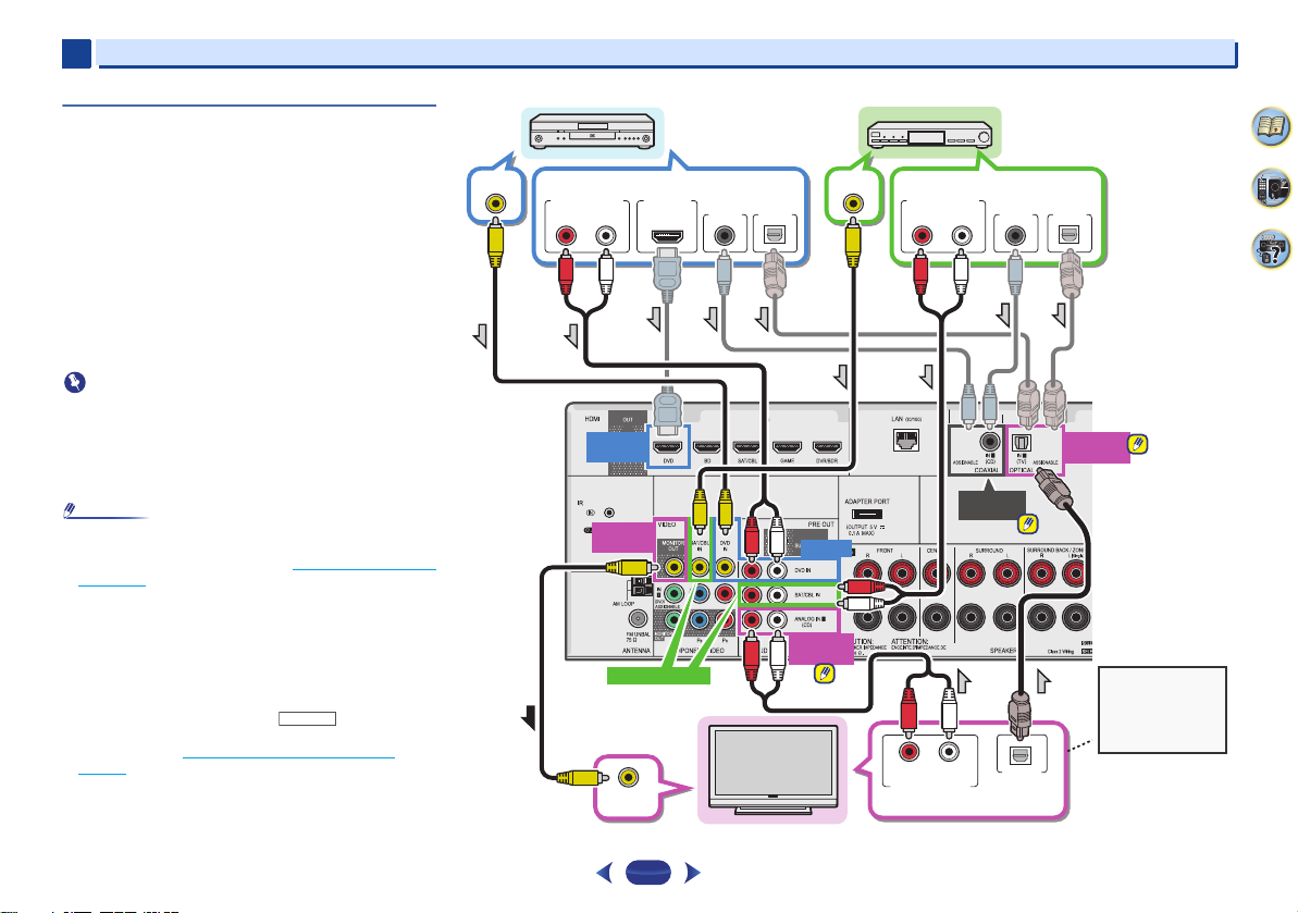
Connecting your equipment
Connecting your TV with no HDMI input
This diagram shows connections of a TV (with no HDMI input)
and DVD player (or other playback component) to the receiver.
•
With these connections, the picture is not output to the TV
even if the DVD player is connected with an HDMI cable.
Connect the DVD player’s video signals using a composite
cable.
•
In order to listening to HD audio with this receiver, connect
an HDMI cable, and use analog video cable for video signal
input.
Depending on the player, it may not be possible to output
video signals to both HDMI and other video output
(composite, etc.) simultaneously, and it may be necessary
to make video output settings. Please refer to the operating
instructions supplied with your player for more information.
•
When the receiver and TV are connected by composite
cable, the OSD function allowing display of the receiver’s
settings, operations, etc., on the TV’s screen cannot be
used. In this case, watch the receiver’s front panel display
while performing the various operations and making
settings.
•
•
In order to listen to the audio from the TV that is connected
to this receiver using a analog audio cables, set-up for
analog audio input is required (see The Input Assign menu
on page 51).
Only one component can be connected to both the optical
input terminal and coaxial input terminal. If connecting
other devices, please use a different method to connect the
audio.
In order to listen to the audio from the source component
that is connected to this receiver using an optical cable or
a coaxial cable, first, switch to the DVD (DVD player) or
SAT/CBL (set-top box), then use and
to choose the audio signal O1 (OPTICAL1) or C1
SEL
(COAXIAL1) (see Selecting the audio input signal
page 25).
SIGNAL
on
4
7
62
18
2
Important
Note
Bluetooth® ADAPTER
VSX-1023
to LAN port
LAN cable (sold
separately)
Router
Modem
Internet
VSX-1023
PC
2
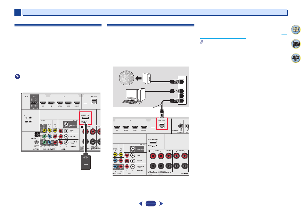
Connecting your equipment
Connecting optional
When the Bluetooth ADAPTER (Pioneer Model No. AS-BT100
or AS-BT200) is connected to this unit, a product equipped
with Bluetooth wireless technology (portable cell phone,
digital music player, etc.) can be used to listen to music
wirelessly.
Connect a
terminal on the rear panel.
•
For instructions on playing the Bluetooth wireless
technology device, see Pairing the
Bluetooth
•
Do not move the receiver with the Bluetooth ADAPTER
connected. Doing so could cause damage or faulty contact.
Bluetooth
wireless technology device on page 31.
Bluetooth® ADAPTER
ADAPTER to the ADAPTER PORT
Bluetooth
ADAPTER and
Connecting to the network through LAN
interface
By connecting this receiver to the network via the LAN
terminal, you can listen to Internet radio stations. To listen to
Internet radio stations, you must sign a contract with an ISP
(Internet Service Provider) beforehand.
When connected in this way, you can play audio files stored
on the components on the local network, including your
computer.
WAN
LAN
1
2
3
Turn on the DHCP serv er function of y our router. In case your
router does not have the built-in DHCP server function, it is
necessary to set up the network manually. For details, see The
Network Setup menu on page 42.
•
Refer to the operation manual of the equipment you have as
the connected equipment and connection method may
differ depending on your Internet environment.
•
When using a broadband Internet connection, a contract
with an Internet service provider is required. For more
details, contact your nearest Internet service provider.
4
7
62
Connect the LAN terminal on this receiver to the LAN terminal
on your router (with or without the built-in DHCP server
function) with a straight LAN cable (CAT 5 or higher).
19
2
Note
2
1
3
4
fig. a
fig. b
FM UNBAL
75
F connector
Outdoor
antenna
5 m to 6 m
(16 ft. to 20 ft.)
Indoor antenna
(vinyl-coated
wire)
IN
IR
Other component
Closet or shelving unit
IR receiver
2
Connecting your equipment
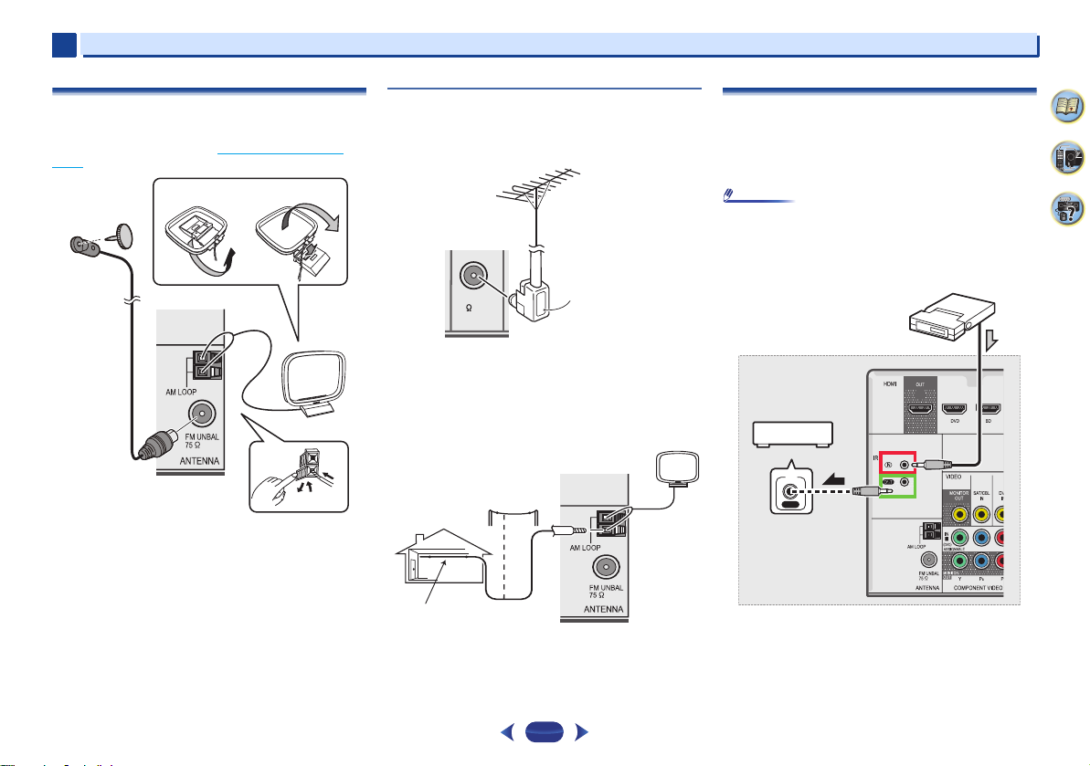
Connecting antennas
Connect the AM loop antenna and the FM wire antenna as
shown below. To improve reception and sound quality,
connect external antennas (see Using external antennas
below).
1
Push open the tabs, then insert one wire fully into each
terminal, then release the tabs to secure the AM antenna
wires.
2
Fix the AM loop antenna to the attached stand.
To fix the stand to the antenna, bend in the direction indicated
by the arrow (fig. a) then clip the loop onto the stand (fig. b).
3
Place the AM antenna on a flat surface and in a direction
giving the best reception.
4
Connect the FM wire antenna into the FM antenna
socket.
For best results, extend the FM antenna fully and fix to a wall
or door frame. Don’t drape loosely or leave coiled up.
Using external antennas
To improve FM reception
Use an F connector (not supplied) to connect an external FM
antenna.
To improve AM reception
Connect a 5m to 6m (16ft. to 20 ft.) length of vinyl-coated
wire to the AM antenna terminal without disconnecting the
supplied AM loop antenna.
For the best possible reception, suspend horizontally
outdoors.
20
Connecting an IR receiver (VSX-1023 only)
If you keep your stereo components in a closed cabinet or
shelving unit, or you wish to use the sub zone remote control
in another zone, you can use an optional IR receiver (such as
a Niles or Xantech unit) to control your system instead of the
remote sensor on the front panel of this receiver.
•
Remote operation may not be possible if direct light from a
strong fluorescent lamp is shining on the IR receiver
remote sensor window.
•
Note that other manufacturers may not use the IR terminology.
Refer to the manual that came with your component to check for
IR compatibility.
Connect the IR receiver sensor to the IR IN jack on the
rear of this receiver.
For more information on connecting the IR receiver, see the
Installation Instructions for the IR Receiver.
4
7
62
2
Note
Note
iPod/iPhone/iPad
USB cable that
comes with the iPod
iPod/iPhone/iPad
iPod cable
USB mass
storage device
2
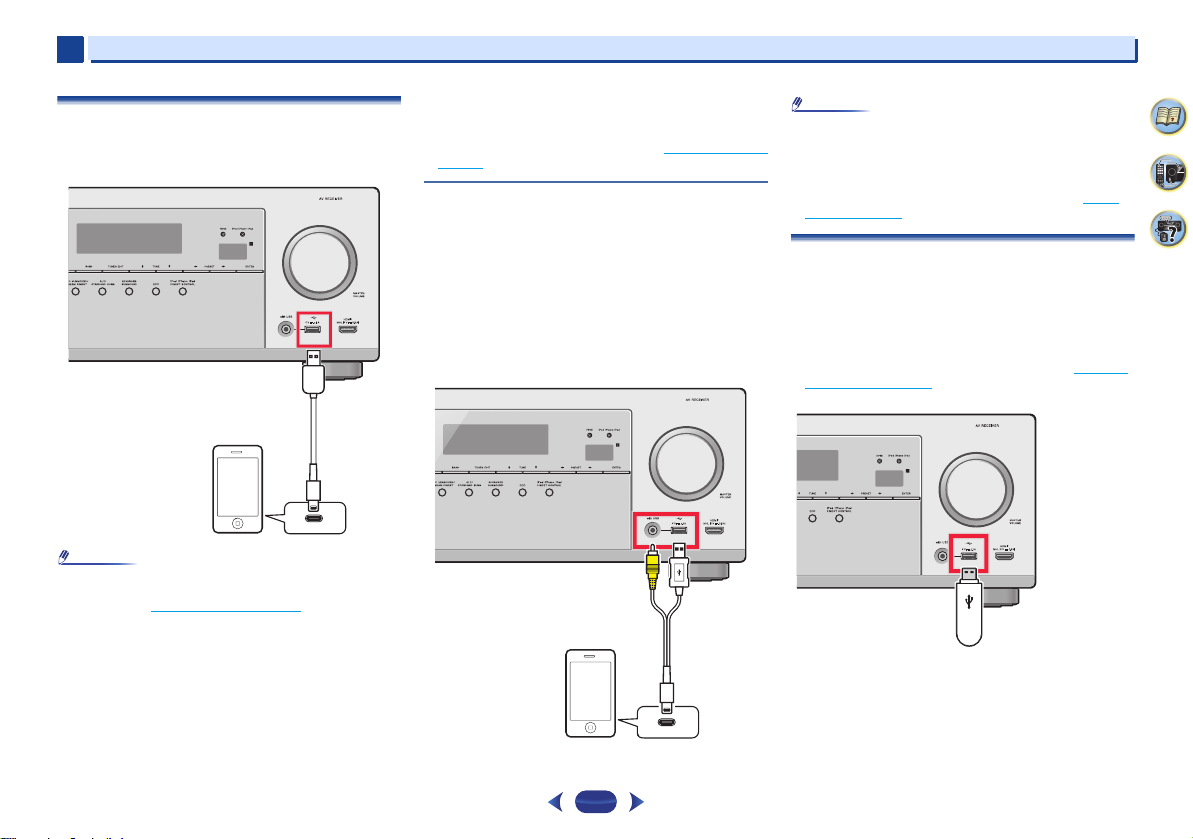
Connecting an iPod
This receiver has a dedicated iPod/iPhone/iPad terminals that
will allow you to control playback of audio content from your
iPod using the controls of this receiver.
•
An iPod/iPhone/iPad can be connected to the receiver. For
details on supported models and versions of the respective
products, see Playing an iPod
Switch the receiver into standby, and then use the iPod
cable to connect your iPod to the iPod/iPhone/iPad
terminals on the front panel of this receiver.
•
For the cable connection, also refer to the operating
instructions for your iPod.
•
When connecting an iPhone to this unit, keep the iPhone
at least 20 cm away from this unit. If the iPhoneis kept
closer to this unit and a telephone call is received by the
iPhone, noise may be output from this device.
on page 27.
•
iPod recharging occurs whenever an iPod is connected to
this unit. (Recharging is enabled only when the unit’s
power is turned on.)
•
For instructions on playing the iPod, see Playing an iPod on
page 27.
Use a dedicated cable to enjoy iPod video
If an iPod is connected using a dedicated iPod connection
cable (sold separately), then video from the iPod can also be
enjoyed on a TV that is connected to the receiver.
•
The iPod cable is not included with this receiver. The
optional iPod cable from Pioneer is sold separately under
the part number L308102013030-IL. Contact the Pioneer
Customer Support division for more information on
obtaining an optional iPod cable.
•
iPhone5, iPad 4th generation, iPad mini, iPod touch 5th
generation and iPod nano 7th generation cannot be
connected using a separately sold iPod cable.
Connecting your equipment
•
Due to linked operation of the HDMI control function, if a
supported TV and receiver are connected using a HDMI
cable and the TV input is changed during iPod input, the
receiver may automatically also change to TV input. If this
happens, please either change the receiver’s input back to
iPod, or turn OFF the HDMI control function (see HDMI
Setup on page 55).
Connecting a USB device
It is possible to play audio and photo files by connecting USB
devices to this receiver.
Switch the receiver into standby then connect your USB
device to the iPod/iPhone/iPad terminals on the front panel
of this receiver.
•
This receiver does not support a USB hub.
•
For instructions on playing the USB device, see Playing a
USB device on page 28.
4
7
62
21
 Loading...