

Page 1
Operating Instructions
Mode d’emploi
Инструкции по эксплуатации
Discover the benefits of registering your product online at
http://www.pioneer.co.uk
(or http://www.pioneer.eu).
Découvrez les nombreux avantages offerts en enregistrant votre produit en ligne
maintenant sur
http://www.pioneer.fr
(ou http://www.pioneer.eu).
Зарегистрируйте Baшe изделие на
http://www.pioneer-rus.ru
(или
http://www.pioneer.eu). Oзнакомьтесь с преимуществами регистрации в Интернет
VSX-820
-S/-K
Page 2
IMPORTANT
CAUTION
RISK OF ELECTRIC SHOCK
DO NOT OPEN
The lightning flash with arrowhead symbol,
within an equilateral triangle, is intended to
alert the user to the presence of uninsulated
“dangerous voltage” within the product’s
enclosure that may be of sufficient
magnitude to constitute a risk of electric
shock to persons.
CAUTION:
TO PREVENT THE RISK OF ELECTRIC
SHOCK, DO NOT REMOVE COVER (OR
BACK). NO USER-SERVICEABLE PARTS
INSIDE. REFER SERVICING TO QUALIFIED
SERVICE PERSONNEL.
Replacement and mounting of an AC plug on the power supply cord of this unit should be performed only by qualified
service personnel.
IMPORTANT: THE MOULDED PLUG
This appliance is supplied with a moulded three pin mains plug for your safety and convenience. A 10 amp fuse is fitted in this plug. Should
the fuse need to be replaced, please ensure that the replacement fuse has a rating of 10 amps and that it is approved by ASTA or BSI to
BS1362.
Check for the ASTA mark or the BSI mark on the body of the fuse.
If the plug contains a removable fuse cover, you must ensure that it is refitted when the fuse is replaced. If you lose the fuse cover the plug
must not be used until a replacement cover is obtained. A replacement fuse cover can be obtained from your local dealer.
If the fitted moulded plug is unsuitable for your socket outlet, then the fuse shall be removed and the plug cut off and disposed of
safely. There is a danger of severe electrical shock if the cut off plug is inserted into any 13 amp socket.
If a new plug is to be fitted, please observe the wiring code as shown below. If in any doubt, please consult a qualified electrician.
IMPORTANT: The wires in this mains lead are coloured in accordance with the following code:
Blue : Neutral Brown : Live
As the colours of the wires in the mains lead of this appliance may not correspond with the coloured markings identifying the terminals in
your plug, proceed as follows;
The wire which is coloured BLUE must be connected to the terminal which is marked with the
letter N or coloured BLACK.
The wire which is coloured BROWN must be connected to the terminal which is marked with the
letter L or coloured RED.
How to replace the fuse: Open the fuse compartment with a screwdriver and replace the fuse.
The exclamation point within an equilateral
triangle is intended to alert the user to the
presence of important operating and
maintenance (servicing) instructions in the
literature accompanying the appliance.
D3-4-2-1-1_A1_En
D3-4-2-1-2-2*_A1_En
WARNING
This equipment is not waterproof. To prevent a fire or
shock hazard, do not place any container filled with
liquid near this equipment (such as a vase or flower
pot) or expose it to dripping, splashing, rain or
moisture.
D3-4-2-1-3_A1_En
WARNING
Before plugging in for the first time, read the following
section carefully.
The voltage of the available power supply differs
according to country or region. Be sure that the
power supply voltage of the area where this unit
will be used meets the required voltage (e.g., 230 V
or 120 V) written on the rear panel.
D3-4-2-1-4*_A1_En
WARNING
To prevent a fire hazard, do not place any naked flame
sources (such as a lighted candle) on the equipment.
D3-4-2-1-7a_A1_En
VENTILATION CAUTION
When installing this unit, make sure to leave space
around the unit for ventilation to improve heat radiation
(at least 40 cm at top, 10 cm at rear, and 20 cm at each
side).
WARNING
Slots and openings in the cabinet are provided for
ventilation to ensure reliable operation of the product,
and to protect it from overheating. To prevent fire
hazard, the openings should never be blocked or
covered with items (such as newspapers, table-cloths,
curtains) or by operating the equipment on thick carpet
or a bed.
D3-4-2-1-7b*_A1_En
Page 3
Information for users on collection and disposal of old equipment and used batteries
Symbol for
equipment
Symbol examples
for batteries
Pb
These symbols on the products, packaging, and/or accompanying documents mean
that used electrical and electronic products and batteries should not be mixed with
general household waste.
For proper treatment, recovery and recycling of old products and used batteries,
please take them to applicable collection points in accordance with your national
legislation.
By disposing of these products and batteries correctly, you will help to save valuable
resources and prevent any potential negative effects on human health and the
environment which could otherwise arise from inappropriate waste handling.
For more information about collection and recycling of old products and batteries,
please contact your local municipality, your waste disposal service or the point of sale
where you purchased the items.
These symbols are only valid in the European Union.
For countries outside the European Union:
If you wish to discard these items, please contact your local authorities or dealer and
ask for the correct method of disposal.
K058a_A1_En
Operating Environment
Operating environment temperature and humidity:
+5 °C to +35 °C (+41 °F to +95 °F); less than 85 %RH
(cooling vents not blocked)
Do not install this unit in a poorly ventilated area, or in
locations exposed to high humidity or direct sunlight (or
strong artificial light)
If the AC plug of this unit does not match the AC
outlet you want to use, the plug must be removed
and appropriate one fitted. Replacement and
mounting of an AC plug on the power supply cord of
this unit should be performed only by qualified
service personnel. If connected to an AC outlet, the
cut-off plug can cause severe electrical shock. Make
sure it is properly disposed of after removal.
The equipment should be disconnected by removing
the mains plug from the wall socket when left unused
for a long period of time (for example, when on
vacation).
CAUTION
The STANDBY/ON switch on this unit will not
completely shut off all power from the AC outlet.
Since the power cord serves as the main disconnect
device for the unit, you will need to unplug it from the
AC outlet to shut down all power. Therefore, make
sure the unit has been installed so that the power
cord can be easily unplugged from the AC outlet in
case of an accident. To avoid fire hazard, the power
cord should also be unplugged from the AC outlet
when left unused for a long period of time (for
example, when on vacation).
D3-4-2-1-7c*_A1_En
D3-4-2-2-1a_A1_En
D3-4-2-2-2a*_A1_En
This product is for general household purposes. Any
failure due to use for other than household purposes
(such as long-term use for business purposes in a
restaurant or use in a car or ship) and which requires
repair will be charged for even during the warranty
period.
K041_A1_En
Manufactured under license from Dolby
Laboratories. Dolby, Pro Logic, Surround EX
and the double-D symbol are trademarks of
Dolby Laboratories.
Manufactured under license under U.S.
Patent #’s: 5,451,942; 5,956,674; 5,974,380;
5,978,762; 6,226,616; 6,487,535; 7,212,872;
7,333,929; 7,392,195; 7,272,567 & other U.S.
and worldwide patents issued & pending.
DTS and the Symbol are registered
trademarks, & DTS-HD, DTS-HD Master
Audio, and the DTS logos are trademarks of
DTS, Inc. Product includes software. © DTS,
Inc. All Rights Reserved.
Page 4

Thank you for buying this Pioneer product. Please read through these operating instructions so you
will know how to operate your model properly. After you have finished reading the instructions, put
them away in a safe place for future reference.
Contents
Flow of settings on the receiver
. . 6
01 Before you start
Checking what’s in the box . . . . . . . . . . . . . . . 7
Loading the batteries . . . . . . . . . . . . . . . . . . . 7
Installing the receiver . . . . . . . . . . . . . . . . . . . 7
Ventilation . . . . . . . . . . . . . . . . . . . . . . . . . . 8
02 Controls and displays
Front panel . . . . . . . . . . . . . . . . . . . . . . . . . . . 9
Operating range of remote control . . . . . . . 10
Display . . . . . . . . . . . . . . . . . . . . . . . . . . . . . 11
Remote control . . . . . . . . . . . . . . . . . . . . . . . 13
03 Connecting your equipment
Placing the speakers. . . . . . . . . . . . . . . . . . . 16
Hints on the speaker placement. . . . . . . . . 17
Connecting the speakers . . . . . . . . . . . . . . . 18
Connect the surround back or front
height speakers . . . . . . . . . . . . . . . . . . . . . 19
Switching the speaker system . . . . . . . . . . 20
Making cable connections . . . . . . . . . . . . . . 20
HDMI cables . . . . . . . . . . . . . . . . . . . . . . . 20
About HDMI . . . . . . . . . . . . . . . . . . . . . . . . 21
Analog audio cables. . . . . . . . . . . . . . . . . . 21
Digital audio cables . . . . . . . . . . . . . . . . . . 21
Video cables . . . . . . . . . . . . . . . . . . . . . . . . 21
About video outputs connection . . . . . . . . . . 22
Connecting a TV and playback components
Connecting using HDMI. . . . . . . . . . . . . . . 23
Connecting your component with no
HDMI terminal . . . . . . . . . . . . . . . . . . . . . . 24
Connecting a satellite receiver or other
digital set-top box . . . . . . . . . . . . . . . . . . . . . 25
Connecting an HDD/DVD recorder, VCR
and other video sources . . . . . . . . . . . . . . . . 25
Using the component video jacks . . . . . . . . . 26
Connecting other audio components . . . . . . 26
Connecting antennas . . . . . . . . . . . . . . . . . . 27
Using external antennas. . . . . . . . . . . . . . . 27
Connecting to the front panel video
terminal . . . . . . . . . . . . . . . . . . . . . . . . . . . . 28
Plugging in the receiver . . . . . . . . . . . . . . . . 28
. . . 23
04 Basic Setup
Automatically setting up for surround
sound (MCACC) . . . . . . . . . . . . . . . . . . . . . . 29
Other problems when using the Auto
MCACC Setup. . . . . . . . . . . . . . . . . . . . . . . 31
05 Listening to your system
Basic playback . . . . . . . . . . . . . . . . . . . . . . . 32
Auto playback . . . . . . . . . . . . . . . . . . . . . . . . 33
Listening in surround sound . . . . . . . . . . . . . 33
Using the Advanced surround effects. . . . . 34
Listening in stereo. . . . . . . . . . . . . . . . . . . . . 35
Using Front Stage Surround Advance . . . . . . 35
Using Stream Direct . . . . . . . . . . . . . . . . . . . 36
Using the Sound Retriever. . . . . . . . . . . . . . . 36
Better sound using Phase Control. . . . . . . . . 36
Listening with Acoustic Calibration EQ . . . . . 37
Using surround back channel processing. . . 37
Setting the Up Mix function. . . . . . . . . . . . . . 38
Setting the Audio options . . . . . . . . . . . . . . . 38
Choosing the input signal . . . . . . . . . . . . . . . 41
Using the headphone . . . . . . . . . . . . . . . . . . 41
06 The System Setup menu
Using the System Setup menu . . . . . . . . . . . 42
Manual speaker setup. . . . . . . . . . . . . . . . . . 43
Speaker Setting . . . . . . . . . . . . . . . . . . . . . 43
Crossover Network . . . . . . . . . . . . . . . . . . . 45
Channel Level . . . . . . . . . . . . . . . . . . . . . . . 45
Speaker Distance . . . . . . . . . . . . . . . . . . . . 46
The Input Assign menu . . . . . . . . . . . . . . . . . 46
The Pre Out Setting . . . . . . . . . . . . . . . . . . . . 47
07 Using the tuner
Listening to the radio. . . . . . . . . . . . . . . . . . . 48
Improving FM stereo sound . . . . . . . . . . . . 48
Saving station presets . . . . . . . . . . . . . . . . . . 48
Listening to station presets. . . . . . . . . . . . . 49
Naming preset stations. . . . . . . . . . . . . . . . 49
An introduction to RDS . . . . . . . . . . . . . . . . . 50
Searching for RDS programs . . . . . . . . . . . 50
Displaying RDS information . . . . . . . . . . . . 51
4
En
Page 5

English
Français
Deutsch
Nederlands
Italiano
Español
08 Making recordings
Making an audio or a video recording . . . . . . 52
09
Controlling the rest of your system
Setting the remote to control other
components . . . . . . . . . . . . . . . . . . . . . . . . . 53
Selecting preset codes directly . . . . . . . . . . . 53
Clearing all the remote control settings. . . . . 54
Controls for TVs . . . . . . . . . . . . . . . . . . . . . . . 55
Controls for other components . . . . . . . . . . . 56
Preset Code List . . . . . . . . . . . . . . . . . . . . . . 57
10 Other connections
Connecting an iPod. . . . . . . . . . . . . . . . . . . . 66
Connecting your iPod to the receiver . . . . . 66
iPod playback . . . . . . . . . . . . . . . . . . . . . . . 67
Watching photos and video content . . . . . . 68
About iPod . . . . . . . . . . . . . . . . . . . . . . . . . 68
Connecting a USB device . . . . . . . . . . . . . . . 69
Connecting your USB device to the
receiver. . . . . . . . . . . . . . . . . . . . . . . . . . . . 69
Basic playback controls . . . . . . . . . . . . . . . 69
Compressed audio compatibility. . . . . . . . . 70
Bluetooth® ADAPTER for Wireless
Enjoyment of Music. . . . . . . . . . . . . . . . . . . . 71
Wireless music play . . . . . . . . . . . . . . . . . . 71
Connecting Optional Bluetooth
ADAPTER . . . . . . . . . . . . . . . . . . . . . . . . . . 71
Pairing Bluetooth ADAPTER and
Bluetooth wireless technology device . . . . . 72
Listening to Music Contents of
Bluetooth wireless technology device
with Your System . . . . . . . . . . . . . . . . . . . . 72
English Italiano Français
11 Additional information
Troubleshooting . . . . . . . . . . . . . . . . . . . . . . 74
HDMI . . . . . . . . . . . . . . . . . . . . . . . . . . . . . 77
Important information regarding the
HDMI connection . . . . . . . . . . . . . . . . . . . . 78
iPod messages . . . . . . . . . . . . . . . . . . . . . . 78
USB messages . . . . . . . . . . . . . . . . . . . . . . 79
Resetting the main unit. . . . . . . . . . . . . . . . . 79
Specifications . . . . . . . . . . . . . . . . . . . . . . . . 80
Cleaning the unit. . . . . . . . . . . . . . . . . . . . . . 80
Nederlands
EspañolDeutsch
5
En
Page 6
Flow of settings on the receiver
Front
Left (L)
*Front Height
Left (FHL)
*Front Height
Right (FHR)
Surround
Left (SL)
*Surround Back
Left (SBL)
*Surround Back
Right (SBR)
Surround
Right (SR)
Center (C)
Subwoofer (SW)
Listening
position
Front
Right (R)
The unit is a full-fledged AV receiver equipped
with an abundance of functions and terminals.
It can be used easily after following the
procedure below to make the connections and
settings.
The colors of the steps indicate the following:
Required setting item
Setting to be made as necessary
1
Before you start
• Checking what’s in the box (page 7)
• Loading the batteries (page 7)
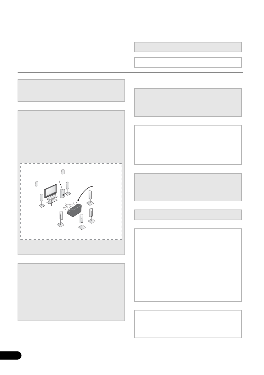
2
Connecting the speakers
Where you place the speakers will have a big
effect on the sound. Place your speakers as
shown below for the best surround sound effect.
• Placing the speakers (page 16)
• Connecting the speakers (page 18)
• Connect the surround back or front height
speakers (page 19)
You can connect only one of either the surround back
speaker or the front height speaker.
3
Connecting the components
For surround sound, you’ll want to hook up
using a digital connection from the BD/DVD
player to the receiver.
• About video outputs connection (page 22)
6
En
• Connecting a TV and playback components
• Connecting antennas (page 27)
• Plugging in the receiver (page 28)
(page 23)
4
Power On
Make sure you’ve set the video input on your TV to
this receiver. Check the manual that came with
the TV if you don’t know how to do this.
5
The Pre Out Setting (page 47)
(When connecting the front height speakers.)
The Input Assign menu (page 46)
(When using connections other than the
recommended connections.)
6
Use the on-screen automatic MCACC
setup to set up your system
• Automatically setting up for surround sound
(MCACC) (page 29)
7
Basic playback (page 32)
8
Adjusting the sound as desired
•Using the various listening modes
• Using the Sound Retriever (page 36)
• Better sound using Phase Control (page 36)
• Listening with Acoustic Calibration EQ
(page 37)
• Using surround back channel processing
(page 37)
• Setting the Up Mix function (page 38)
• Setting the Audio options (page 38)
• Choosing the input signal (page 41)
• Manual speaker setup (page 43)
9
Making maximum use of the remote
control
• Setting the remote to control other
components (page 53)
Page 7
Before you start 01
English
Français
Deutsch
Nederlands
Italiano
Español
Chapter 1:
Before you start
• Batteries with the same shape may have
Checking what’s in the box
Please check that you’ve received the following
supplied accessories:
• Setup microphone
• Remote control
• Dry cell batteries (AAA size IEC R03) x2
• AM loop antenna
•FM wire antenna
• iPod cable
•Power cord
• Warranty card
• These operating instructions
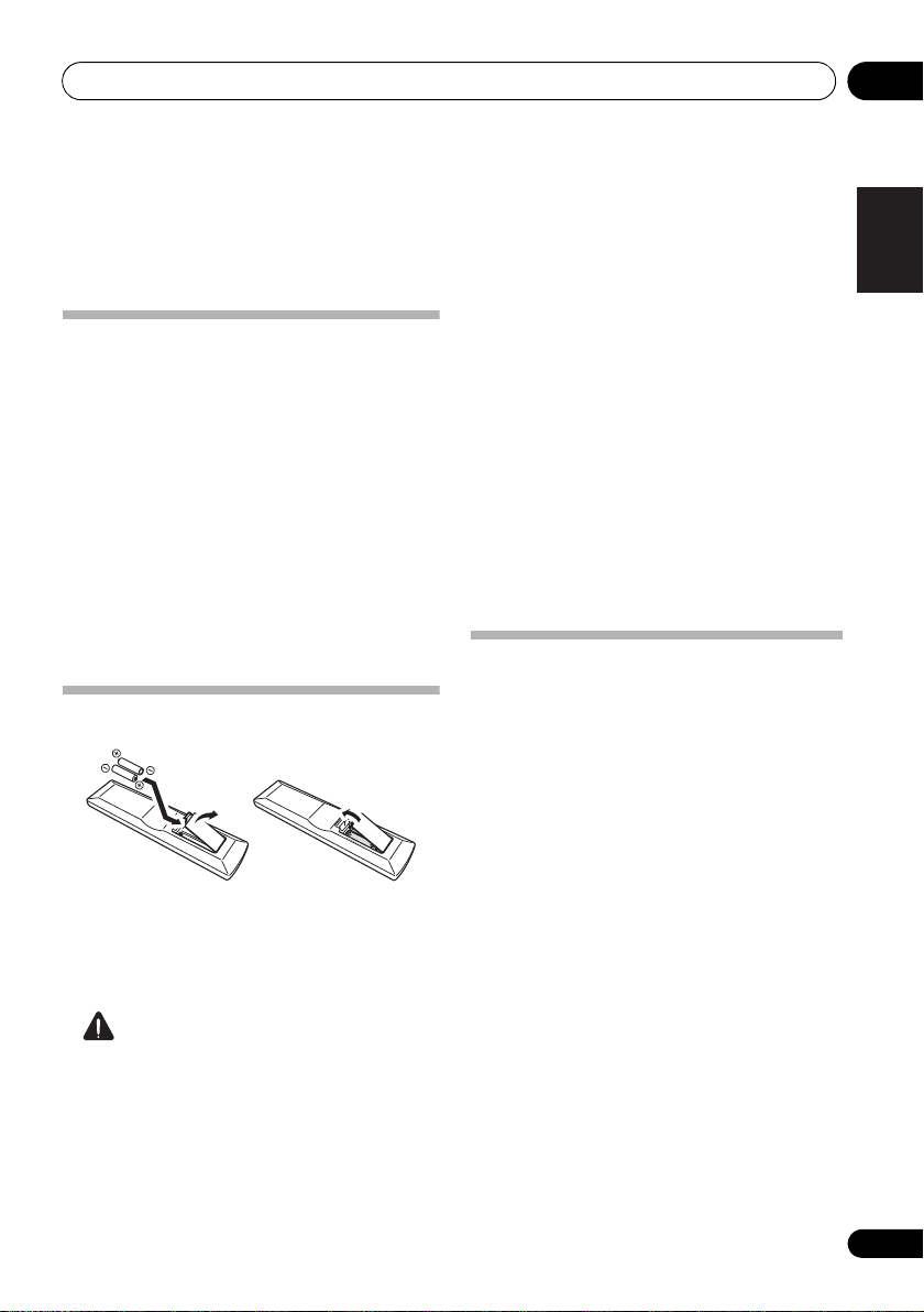
Loading the batteries
The batteries included with the unit are to
check initial operations; they may not last over
a long period. We recommend using alkaline
batteries that have a longer life.
CAUTION
Incorrect use of batteries may result in such
hazards as leakage and bursting. Observe the
following precautions:
• Never use new and old batteries together.
• Insert the plus and minus sides of the
batteries properly according to the marks
in the battery case.
different voltages. Do not use different
batteries together.
• When disposing of used batteries, please
comply with governmental regulations or
environmental public instruction’s rules
that apply in your country or area.
• Do not use or store batteries in direct
sunlight or other excessively hot place,
such as inside a car or near a heater. This
can cause batteries to leak, overheat,
explode or catch fire. It can also reduce
the life or performance of batteries.
Installing the receiver
• When installing this unit, make sure to put
it on a level and stable surface.
Don’t install it on the following places:
– on a color TV (the screen may distort)
– near a cassette deck (or close to a device
that gives off a magnetic field). This may
interfere with the sound.
– in direct sunlight
– in damp or wet areas
– in extremely hot or cold areas
– in places where there is vibration or other
movement
– in places that are very dusty
– in places that have hot fumes or oils (such as
a kitchen)
7
En
Page 8
Before you start01
Receiver
40 cm
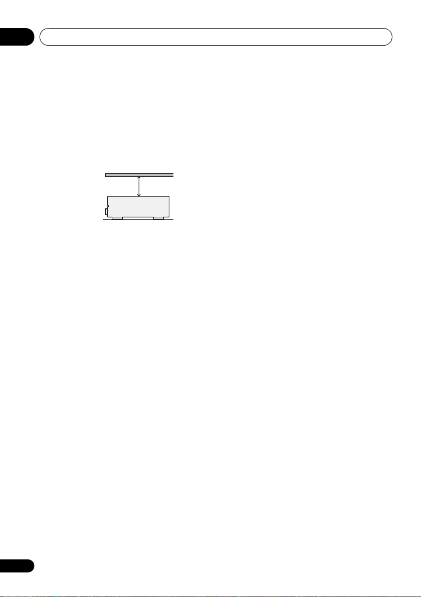
Ventilation
When installing this unit, make sure to leave
space around the unit for ventilation to improve
heat dispersal (at least 40 cm at the top). If not
enough space is provided between the unit and
walls or other equipment, heat will build up
inside, interfering with performance and/or
causing malfunctions.
Slot and openings in the cabinet are provided
for ventilation and to protect the equipment
from overheating. To prevent fire hazard, do not
place anything directly on top of the unit, make
sure the openings are never blocked or covered
with items (such as newspapers, table-cloths
and curtains), and do not operate the
equipment on thick carpet or a bed.
8
En
Page 9
Controls and displays 02
English
Français
Deutsch
Nederlands
Italiano
Español
SPEAKERS
AUTO/DIRECT STEREO/ALC STANDARD
LISTENING MODE
ADV SURROUND DIRECT CONTROL
iPod iPhone
DIMMER DISPLAY BAND TUNE TUNER EDIT PRESET ENTER
PHONES
INPUT
SELECTOR
STANDBY/ON
PHASE
CONTROL
MASTER
VOLUME
MCACC
SETUP MIC
AUDIO/VIDEO MULTI- CHANNEL RECEIVER
VSX
-820
VIDEO INPUT
AUDIOLRVIDEO
iPod
iPhone
USB
1 27854 63
9
1110 141312
Note
Chapter 2:
Controls and displays
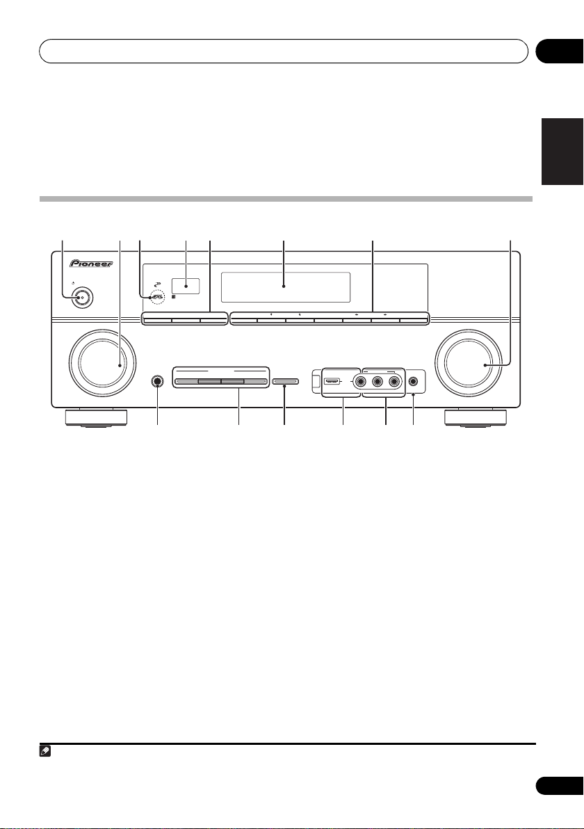
Front panel
1
STANDBY/ON
2
INPUT SELECTOR
dial
Selects an input source.
3
MCACC
indicator
Lights when Acoustic Calibration EQ (page 37)
is on (Acoustic Calibration EQ is automatically
set to on after the Auto MCACC Setup
(page 29)).
4 Remote sensor
Receives the signals from the remote control
(see Operating range of remote control on
page 10).
5
SPEAKERS
Use to change the speaker system (page 20).
DIMMER
Dims or brightens the display. The
brightness can be controlled in four steps.
1 The Pre Out setting may or may not be displayed, depending on the input source you have selected.
DISPLAY
Switches the display of this unit. The
listening mode, sound volume, Pre Out
setting or input name can be checked by
selecting an input source.
6 Character display
See Display on page 11.
7 Tuner control buttons
BAND
Switches between AM, FM ST (stereo) and
FM MONO radio bands (page 48).
TUNE /
Used to find radio frequencies (page 48).
TUNER EDIT
Use with TUNE /, PRESET / and
ENTER to memorize and name stations for
recall (page 48, 49).
1
9
En
Page 10
Controls and displays02
30°
7 m
30°
PRESET /
Use to select preset radio stations
(page 49).
8
MASTER VOLUME
PHONES
9
Use to connect headphones. When the
headphones are connected, there is no sound
output from the speakers (page 41).
10 Listening mode buttons
AUTO/DIRECT
Switches between Auto surround mode
(Auto playback on page 33) and Stream
Direct playback. Stream Direct playback
bypasses the tone controls for the most
accurate reproduction of a source
(page 36).
STEREO/ALC
Switches between stereo playback, Auto
level control stereo mode (page 35) and
Front Stage Surround Advance modes
(page 35).
STANDARD
Press for Standard decoding and to switch
between the various 2 Pro Logic II, 2 Pro
Logic IIx, 2 Pro Logic IIz and NEO:6
options (page 32).
ADV SURROUND
Switches between the various surround
modes (page 34).
11
iPod iPhone DIRECT CONTROL
Change the receiver’s input to the iPod and
enable iPod operations on the iPod (page 68).
12
iPod iPhone/USB
Use to connect your Apple iPod or USB mass
storage device as an audio source (page 66
and page 69).
13
AUDIO/VIDEO
See Connecting to the front panel video terminal
on page 28.
jack
dial
terminal
input
14
MCACC SETUP MIC
Use to connect a microphone when
performing Auto MCACC setup.
jack
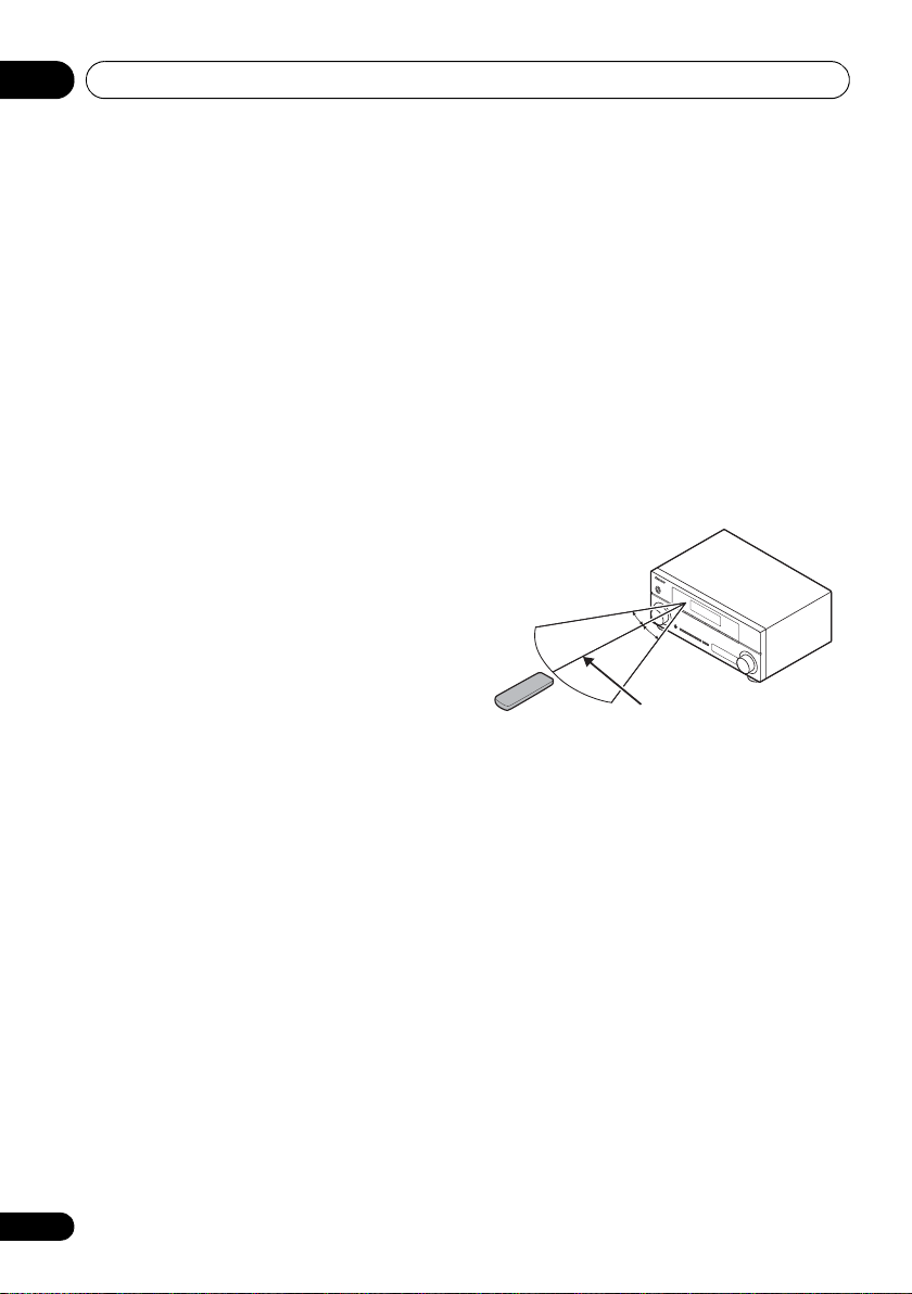
Operating range of remote control
The remote control may not work properly if:
• There are obstacles between the remote
control and the receiver’s remote sensor.
• Direct sunlight or fluorescent light is
shining onto the remote sensor.
• The receiver is located near a device that is
emitting infrared rays.
• The receiver is operated simultaneously
with another infrared remote control unit.
10
En
Page 11
Controls and displays 02
English
Français
Deutsch
Nederlands
Italiano
Español
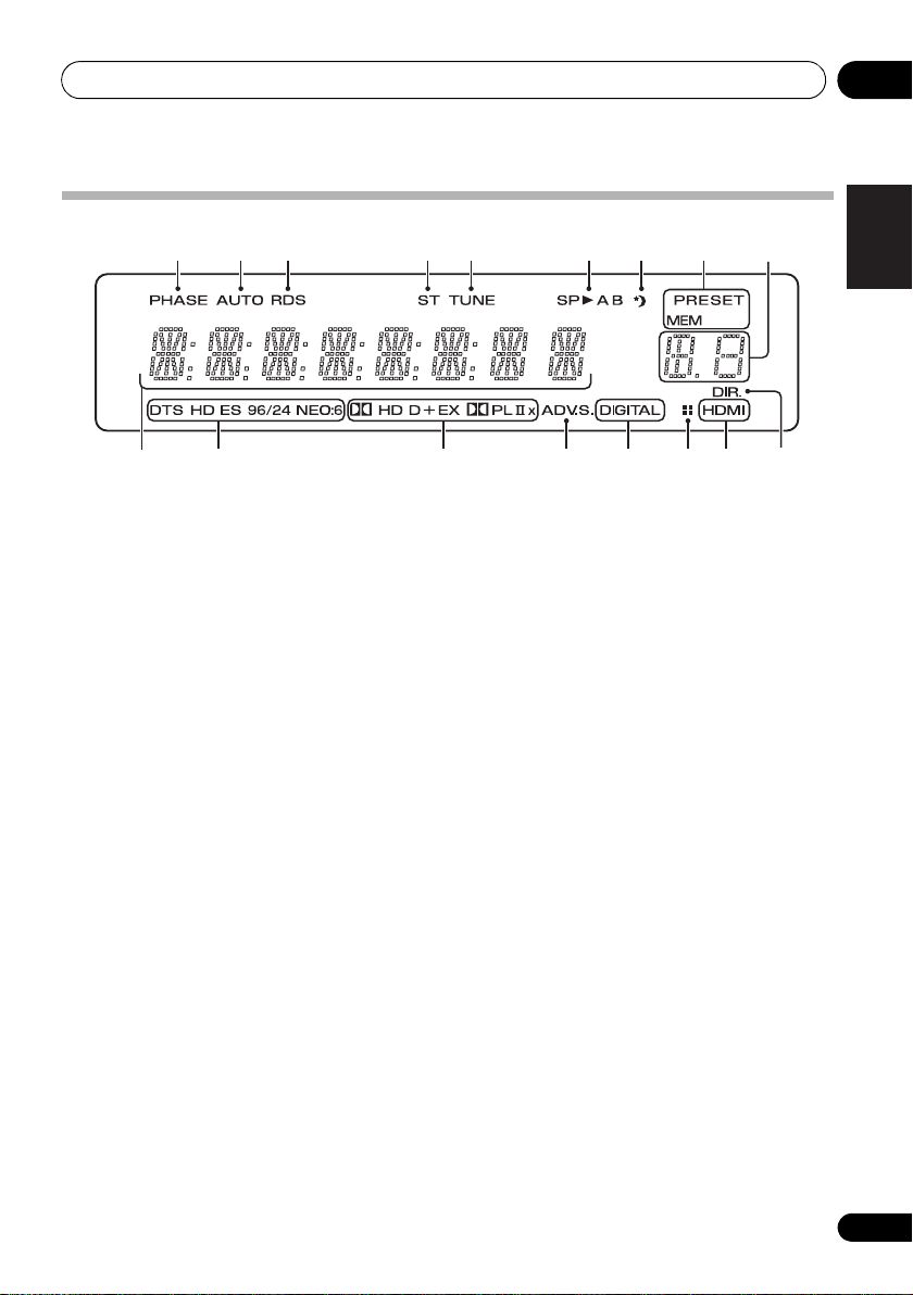
Display
1 2 3 4 5 6 7 8
9
10
1PHASE
Lights when the Phase Control is switched on
(page 36).
2AUTO
Lights when the Auto Surround feature is
switched on (see Auto playback on page 33).
3RDS
Lights when an RDS broadcast is received
(page 50).
4ST
Lights when a stereo FM broadcast is being
received in auto stereo mode.
5TUNE
Lights when a normal broadcast channel is
being received.
6 Speaker indicators
Lights to indicate the current speaker system,
A and/or B (page 20).
7 Sleep timer indicator
Lights when the receiver is in sleep mode
(page 13).
8 Tuner preset indicators
PRESET
Shows when a preset radio station is
registered or called.
MEM
Blinks when a radio station is registered.
11 12 13 14 14 1615
9 PRESET information or input signal
indicator
Shows the preset number of the tuner or the
input signal type, etc.
10 Character display
Displays various system information.
11 DTS indicators
DTS
Lights when a source with DTS encoded
audio signals is detected.
HD
Lights when a source with DTS-EXPRESS
or DTS-HD encoded audio signals is
detected.
ES
Lights to indicate DTS-ES decoding.
96/24
Lights when a source with DTS 96/24
encoded audio signals is detected.
NEO:6
When one of the NEO:6 modes of the
receiver is on, this lights to indicate NEO:6
processing (page 33).
12 Dolby Digital indicators
2D
Lights when a Dolby Digital encoded signal
is detected.
11
En
Page 12

Controls and displays02
2D+
Lights when a source with Dolby Digital
Plus encoded audio signals is detected.
2HD
Lights when a source with Dolby TrueHD
encoded audio signals is detected.
EX
Lights to indicate Dolby Digital EX
decoding.
2PLll(x)
Lights to indicate 2 Pro Logic II / 2 Pro
Logic IIx decoding. Light will go off during
2 Pro Logic IIz decoding (see Listening in
surround sound on page 33 for more on
this).
13 ADV.S.
Lights when one of the Advanced Surround
modes has been selected (see Using the
Advanced surround effects on page 34 for more
on this).
14 SIGNAL SELECT indicators
DIGITAL
Lights when a digital audio signal is
selected.
Blinks when a digital audio signal is
selected and selected audio input is not
provided.
HDMI
Lights when an HDMI signal is selected.
Blinks when an HDMI signal is selected
and selected HDMI input is not provided.
15 Up Mix/DIMMER indicator
Lights when the Up Mix function is set to ON
(see page 37). Also, lights when DIMMER is set
to off.
16 DIR.
Lights when the DIRECT or PURE DIRECT
mode is switched on (page 36).
12
En
Page 13
Controls and displays 02
English
Français
Deutsch
Nederlands
Italiano
Español
RECEIVER
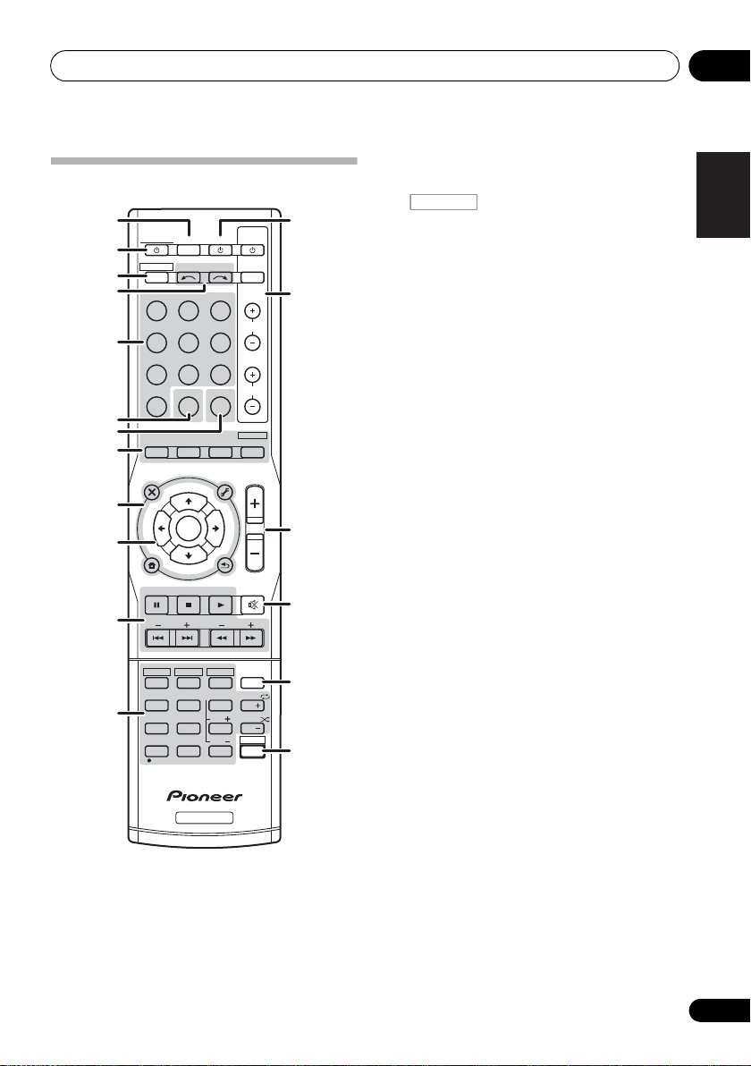
Remote control
1
RECEIVER
2
RECEIVER
3
4
INPUT SELECT
BD DVD
DVR CD
5
ADAPTER i Pod USB
TUNER
S.RETRIEVER
6
7
8
9
10
11
12
AUTO/
DIRECT
AUDIO
PARAMETER
TOP
MENU
T
E
S
E
R
P
HOME
MENU
SETUP
iPod CTRL
PTY SEARCH
HDD
1
4
MIDNIGHT
7
DIMMER
CLR
+
/
BASS
10
STEREO/
A.L.C.
U
T
ENTER
T
U
DVD
SB CH
SPEAKERS
RECEIVER
1
SLEEP
Press to change the amount of time before the
receiver switches into standby (30 min – 60
min – 90 min – Off). You can check the
remaining sleep time at any time by pressing
SLEEP once.
N
E
E
N
2
5
8
0
SOURCESLEEP
TV
CD-R
VIDEO
SIGNAL SEL
STANDARD
TUNER EDIT
TOOLS
P
R
E
S
E
T
RETURN
DTV/ TV
VCR
3
CH SELECT
6
LEV
9
LEV
ENTER
CONTROL
BD MENU
ADV SURR
MENU
BAND
TRE
INPUT
MASTER
VOLUME
MUTE
CH
PHASE
CH
SHIFT
VOL
DISP
EQ
2
RECEIVER
Switches the receiver between standby and on.
3
13
TV
Switches the remote to control the receiver
(used to select the white commands above the
number buttons (MIDNIGHT, etc)). Also use
this button to set up surround sound (page 42)
14
CH
or Audio parameters (page 38).
4
INPUT SELECT
Use to select the input source.
5
MULTI CONTROL
buttons
Press to select control of other components
(see
Controlling the rest of your system on
page 53
).
6
S.RETRIEVER
Press to restore CD quality sound to
compressed audio sources (page 36).
7
SIGNAL SEL
15
Use to select an input signal (page 41).
8 Listening mode buttons
AUTO/DIRECT
Switches between Auto surround mode
16
(Auto playback on page 33) and Stream
Direct playback. Stream Direct playback
bypasses the tone controls for the most
accurate reproduction of a source
17
(page 36).
STEREO/A.L.C.
Switches between stereo playback, Auto
18
level control stereo mode (page 35) and
Front Stage Surround Advance modes
(page 35).
STANDARD
Press for Standard decoding and to switch
between 2 Pro Logic II options (page 33).
ADV SURR
Switches between the various surround
modes (page 34).
Press BD first to access:
BD MENU*
Displays the disc menu of Blu-ray Discs.
13
En
Page 14

Controls and displays02
RECEIVER
Note
RECEIVER
9 System Setup and component control
buttons
The following button controls can be accessed
after you have selected the corresponding
MULTI CONTROL button (BD, DVD, etc.).
Press first to access:
AUDIO PARAMETER
Use to access the Audio options (page 38).
SETUP
Press to access the System Setup menu
(page 42).
RETURN
Confirm and exit the current menu screen.
Press BD, DVD or DVR first to access:
TOP MENU
Displays the disc ‘top’ menu of a BD/DVD.
HOME MENU
Displays the HOME MENU screen.
RETURN
Confirm and exit the current menu screen.
MENU
Displays the TOOLS menu of Blu-ray Disc
player.
Press TUNER first to access:
TUNER EDIT
Memorizes/names stations for recall
(page 48 and 49).
BAND
Switches between AM, FM ST (stereo) and
FM MONO radio bands (page 48).
PTY SEARCH
Use to search for RDS program types
(page 50).
Press iPod USB first to access:
iPod CTRL
Switches between the iPod controls and
the receiver controls (page 68).
10
(TUNE /, PRESET /
),
ENTER
Use the arrow buttons when setting up your
surround sound system (page 42). Also used to
control BD/DVD menus/options.
Use the TUNE / buttons can be used to
find radio frequencies (page 48) and the
PRESET / buttons can be used to select
preset radio stations (page 49).
11 Component control buttons
The main buttons (, , etc.) are used to
control a component after you have selected it
using the input source buttons.
The controls above these buttons can be
accessed after you have selected the
corresponding input source button (BD, DVD,
DVR and CD). These buttons also function as
described below.
RECEIVER
Press first to access:
BASS –/+
Use to adjust Bass
TRE –/+
Use to adjust Treble
1
1
Press TV first to access:
DTV/TV
Switches between the DTV and analog TV
input modes for Pioneer TVs.
12 Number buttons and other component
controls
Use the number buttons to directly select a
radio frequency (page 48) or the tracks on a
CD, etc. There are other buttons that can be
accessed after the button is
pressed. (For example MIDNIGHT, etc.)
HDD*, DVD*, VCR*
These buttons switch between the hard
disk, DVD and VCR controls for HDD/DVD/
VCR recorders.
14
En
1 The tone controls are disabled when the listening mode is set to DIRECT or PURE DIRECT.
Page 15

Controls and displays 02
English
Français
Deutsch
Nederlands
Italiano
Español
Note
SB CH
Press to select ON, AUTO, OFF the
surround back channel.
CH SELECT
Press repeatedly to select a channel, then
use LEV +/– to adjust the level (page 45).
LEV +/–
Use to adjust the channel level.
EQ
Press to switch on/off Acoustic Calibration
EQ setting (page 37).
MIDNIGHT
Switches to Midnight or Loudness
listening (page 39).
SPEAKERS
Use to change the speaker system
(page 20).
PHASE
Press to switch on/off Phase Control
(page 36).
DIMMER
Dims or brightens the display. The
brightness can be controlled in four steps.
13
SOURCE
Press to turn on/off other components
connected to the receiver (see page 56 for
more on this).
14
TV CONTROL
These buttons are dedicated to control the TV
assigned to the TV button. Thus if you only
have one TV to hook up to this system assign it
to the TV button (see page 55 for more on this).
Use to turn on/off the power of the TV.
INPUT
Use to select the TV input signal.
CH +/–
Use to select channels.
buttons
VOL +/–
Use to adjust the volume on your TV.
15
MASTER VOLUME
Use to set the listening volume.
16
MUTE
Mutes/unmutes the sound.
17
DISP
Switches the display of this unit. The listening
mode, sound volume, Pre Out setting or input
name can be checked by selecting an input
1
source.
18
SHIFT
Press to access the ‘boxed’ commands (above
the buttons) on the remote. These buttons are
marked with an asterisk (* ) in this section.
+/–
1 The Pre Out setting may or may not be displayed, depending on the input source you have selected.
15
En
Page 16
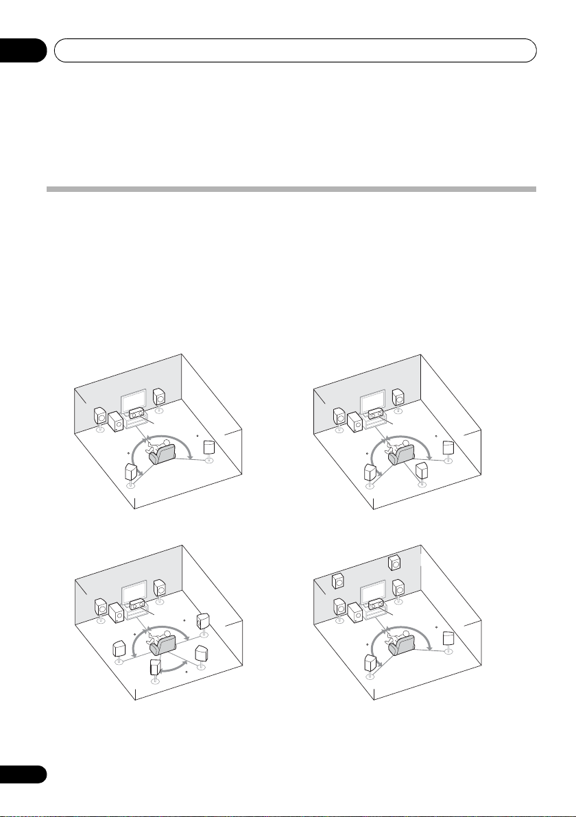
Connecting your equipment03
5.1 channel surround system:
7.1 channel surround
(Surround back) system:
a
7.1 channel surround
(Front height) system:
a
6.1 channel surround
(Surround back) system:
a
Chapter 3:
Connecting your equipment
Placing the speakers
By connecting the left and right front speakers (L/R), the center speaker (C), the left and right
surround speakers (SL/SR), and the subwoofer (SW), a 5.1 ch surround system can be enjoyed.
Further, by using an external amplifier, you can connect the left and right surround back speakers
(
SBL/SBR
surround system.
To achieve the best possible surround sound, install your speakers as shown below.
) and the left and right front height speaker (
FHL/FHR
) to boost your system up to a 7.1 ch
• You can also connect one surround back speaker (SB) and enjoy a 6.1 ch surround system.
L
SW
120
SL
L
SW
90
SL
SBL
a. This layout is available only when the additional amplifier is connected to the unit and the surround back
or front height speakers are connected to the amplifier. For details, see Connect the surround back or front height
speakers on page 19.
16
En
R
L
C
120
R
C
90
SR
SR
SBR
60
SW
120
FHL
L
SW
120
R
C
120
SR
SB
SL
FHR
R
C
120
SR
SL
Page 17

Connecting your equipment 03
English
Français
Deutsch
Nederlands
Italiano
Español
Hints on the speaker placement
Where you put your speakers in the room has a
big effect on the quality of the sound. The
following guidelines should help you to get the
best sound from your system.
• The subwoofer can be placed on the floor.
Ideally, the other speakers should be at
about ear-level when you’re listening to
them. Putting the speakers on the floor
(except the subwoofer), or mounting them
very high on a wall is not recommended.
• For the best stereo effect, place the front
speakers 2 m to 3 m apart, at equal
distance from the TV.
• If you’re going to place speakers around
your CRT TV, use shielded speakers or
place the speakers at a sufficient distance
from your CRT TV.
• If you’re using a center speaker, place the
front speakers at a wider angle. If not, place
them at a narrower angle.
• Place the center speaker above or below
the TV so that the sound of the center
channel is localized at the TV screen. Also,
make sure the center speaker does not
cross the line formed by the leading edge
of the front left and right speakers.
• It is best to angle the speakers towards the
listening position. The angle depends on
the size of the room. Use less of an angle
for bigger rooms.
• Surround and surround back speakers
should be positioned 60 cm to 90 cm
higher than your ears and titled slight
downward. Make sure the speakers don’t
face each other. For DVD-Audio, the
speakers should be more directly behind
the listener than for home theater
playback.
• If the surround speakers cannot be set
directly to the side of the listening position
with a 7.1-channel system, the surround
effect can be enhanced by turning off the
Up Mix function (see Setting the Up Mix
function on page 38).
• Try not to place the surround speakers
farther away from the listening position
than the front and center speakers. Doing
so can weaken the surround sound effect.
• Place the left and right front height
speakers at least one meter directly above
the left and right front speakers.
CAUTION
• Make sure that all speakers are securely
installed. This not only improves sound
quality, but also reduces the risk of
damage or injury resulting from speakers
being knocked over or falling in the event
of external shocks such as earthquakes.
Important
• To connect the surround back or front
height speakers, an additional amplifier is
required. Connect the additional amplifier
to the PRE OUT SURR BACK/FRONT
HEIGHT outputs of this unit and connect
the surround back or front height speakers
to the additional amplifier (see Connect
the surround back or front height speakers
on page 19).
The Pre Out setting must be set if the above
connections are performed. Select
SURR.BACK if the surround back speaker
is connected and HEIGHT if the front
height speaker is connected (If neither the
surround back speaker nor the front height
speaker is connected, either setting will
suffice) (see The Pre Out Setting on
page 47).
17
En
Page 18
Connecting your equipment03
AC IN
SURR BACK /
FRONT
HEIGHT
L
(
Single
)
R
R
L
IN
R
L
IN
IN
OUT
IN
CD
TV/SAT
DVD BD
DVR/VCR
MONITOR OUT
PRPBY
RL
DVD IN BD IN
OUT
MONITOR
COMPONENT VIDEO
TV/SAT
IN
DVR/VCR
OUT IN
FRONT
RL
CD-R/TAPE
DVR/VCR
CD-R/TAPE
PRE OUT
AUDIO
ADAPTER PORT
VIDEO
(
OUTPUT 5 V 100 mA MAX
)
(BD)
IN
1
(
DVD
)
IN
2
ASSIGNABLE
SPEAKERS
1
B
SPEAKERS
A
2
ANTENNA
FM
UNBAL
75
AM
LOOP
VOLTAGE SELECTOR
110-127 V 220-240 V
SUBWOOFER
PRE OUT
CENTER
SURROUND
RL
SW
L
C
RSLSR
LR
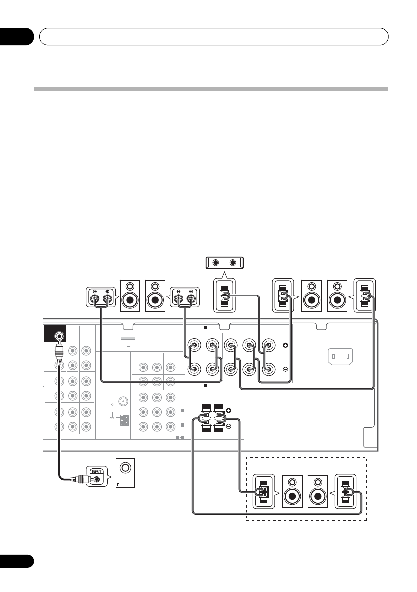
Center speaker
Surround speakers
Front speakers
Powered subwoofer
Speaker system B
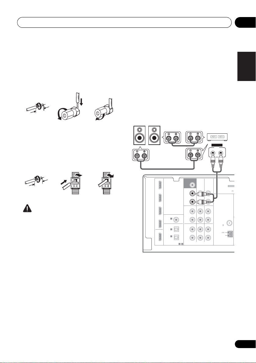
Connecting the speakers
The receiver will work with just two stereo
speakers (the front speakers in the diagram)
but using at least three speakers is
recommended, and a complete setup is best
for surround sound.
Make sure you connect the speaker on the
right to the right (R) terminal and the speaker
on the left to the left (L) terminal. Also make
sure the positive and negative (+/–) terminals
on the receiver match those on the speakers.
You can use the speakers connected to the B
speaker terminals to listen to stereo playback
in another room. See Switching the speaker
system on page 20 for the listening options
with this setup.
You can use speakers with a normal
impedance between 6 Ω and 16 Ω.
However, note that only the front speakers are
set to a value between 12 Ω and 16 Ω if you
select SPAB in Switching the speaker system
on page 20.
Be sure to complete all connections before
connecting this unit to the AC power source.
18
En
Page 19
Connecting your equipment 03
English
Français
Deutsch
Nederlands
Italiano
Español
10 mm
12 3
10 mm
IN BD
SURR BACK /
FRONT
HEIGHT
L
(
Single
)
R
R
L
IN
R
L
IN
IN
OUT
IN
CD
TV/SAT
DVD BD
DVR/VCR
M
CD-R/TAPE
DVR/VCR
CD-R/TAPE
PRE OUT
DVD
TV/SAT
COAXIAL
OPTICAL
(CD)
IN
ASSIGNABLE
ASSIGNABLE
OUT
HDMI
DVR/VCR
1
(
CD-R/TAPE
)
IN
AUDIO
ADAPTER
(
OUTPUT 5 V 1
1
1 2
IN
2
SUBWOOFER
PRE OUT
ANTENNA
FM
UNBAL
75
AM
LOOP
INPUT
LR
ANALOG
SBL/FHL SBR/FHR
Surround back or
front height speakers
Surround back or
front height
channel amplifier
Bare wire connections
A-Speaker terminals:
1 Twist exposed wire strands together.
2 Loosen terminal and insert exposed wire.
3 Tighten terminal.
123
B-Speaker terminals:
1 Twist exposed wire strands together.
2 Push open the tabs and insert exposed
wire.
3 Release the tabs.
CAUTION
• These speaker terminals carry
HAZARDOUS LIVE voltage. To prevent
the risk of electric shock when connecting
or disconnecting the speaker cables,
disconnect the power cord before touching
any uninsulated parts.
• Make sure that all the bare speaker wire is
twisted together and inserted fully into the
speaker terminal. If any of the bare speaker
wire touches the back panel it may cause
the power to cut off as a safety measure.
Connect the surround back or front height speakers
Connect the PRE OUT outputs of the unit and
additional amplifier to add a surround back or
front height speaker.
• If the surround back speaker or the front
height speaker is connected, set the Pre
Out setting (see The Pre Out Setting on
page 47).
• You can use the additional amplifier on the
surround back channel pre-outs for a
single speaker as well. In this case plug the
amplifier into the left (L (Single)) terminal
only.
19
En
Page 20
Connecting your equipment03
Note
SPEAKERS DIMMER DISPLAY
HDMI cable
Switching the speaker system
Three speaker system settings are possible
using the SPEAKERS button.
• Use the SPEAKERS button on the front
panel to select a speaker system setting.
Press repeatedly to choose a speaker system
option:
• SPA – Sound is output from the speakers
connected to the A speaker terminals and
PRE OUT SURR BACK/FRONT HEIGHT
(multichannel playback is possible).
• SPB – Sound is output from the two
speakers connected to speaker system B
(only stereo playback is possible).
• SPAB – Sound is output from speaker
system A, the two speakers in speaker
system B, and the subwoofer.
Multichannel sources are downmixed only
when the STEREO or ALC mo de is selec ted
for stereo output from speaker systems A
2
and B.
• SP – No sound is output from the
speakers.
1
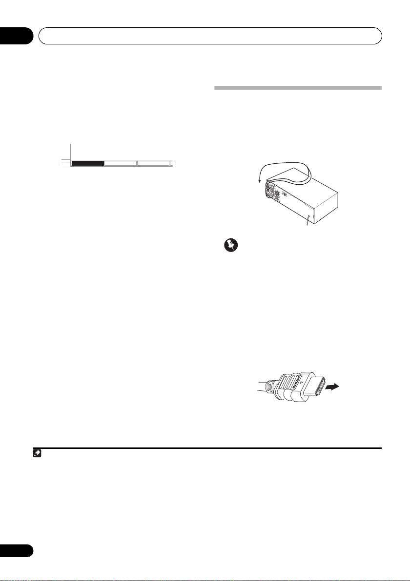
Making cable connections
Make sure not to bend the cables over the top
of this unit (as shown in the illustration). If this
happens, the magnetic field produced by the
transformers in this unit may cause a
humming noise from the speakers.
Important
• Before making or changing connections,
switch off the power and disconnect the
power cord from the AC outlet.
• Before unplugging the power cord, switch
the power into standby.
HDMI cables
Both video and sound signals can be transmitted
simultaneously with one cable.
player and the TV via this receiver, for both
connections, use HDMI cables.
If connecting the
3
Be careful to connect the terminal in the
proper direction.
1 The subwoofer output depends on the settings you made in Speaker Setting on page 43. However, if SPB is selected above,
no sound is heard from the subwoofer (the LFE channel is not downmixed).
2 You can use speakers with a normal impedance between 6 Ω and 16 Ω. However, be aware that only the front speakers are set
to a value between 12 Ω and 16 Ω when you select SPAB.
3 • Set the HDMI parameter in Setting the Audio options on page 38 to THRU (THROUGH) and set the input signal in Choosing
the input signal on page 41 to HDMI, if you want to hear HDMI audio output from your TV (no sound will be heard from this
receiver).
• If the video signal does not appear on your TV, try adjusting the resolution settings on your component or display. Note that
some components (such as video game units) have resolutions that may not be displayed. In this case, use a (analog)
composite connection.
• When the video signal from the HDMI is 480i, 480p, 576i or 576p, Multi Ch PCM sound and HD sound cannot be received.
20
En
Page 21
Connecting your equipment 03
English
Français
Deutsch
Nederlands
Italiano
Español
Note
Right (red)
Analog audio cables
Left (white)
Standard RCA video cable
About HDMI
The HDMI connection transfers
uncompressed digital video, as well as almost
every kind of digital audio that the connected
component is compatible with, including DVDVideo, DVD-Audio, SACD, Dolby Digital Plus,
Dolby TrueHD, DTS-HD Master Audio (see
below for limitations), Video CD/Super VCD
and CD.
This receiver incorporates High-Definition
Multimedia Interface (HDMI
This receiver supports the functions described
below through HDMI connections.
• Digital transfer of uncompressed video
(contents protected by HDCP (1080p/24,
1080p/60, etc.))
• 3D signal transfer
• Deep Color signal transfer
• x.v.Color signal transfer
• Input of multi-channel linear PCM digital
audio signals (192 kHz or less) for up to 8
channels
•
Input of the following digital audio formats:
– Dolby Digital, Dolby Digital Plus, DTS,
High bitrate audio (Dolby TrueHD, DTS-HD
Master Audio), DVD-Audio, CD, SACD
(DSD signal), Video CD, Super VCD
HDMI, the HDMI Logo and High-Definition
Multimedia Interface are trademarks or
reg is te re d t ra de ma rk s o f H DM I L ic en si ng , L LC in
the United States and other countries.
“x.v.Color” and x.v.Color logo are trademarks of
Sony Corporation.
2
®
) technology.
2
2
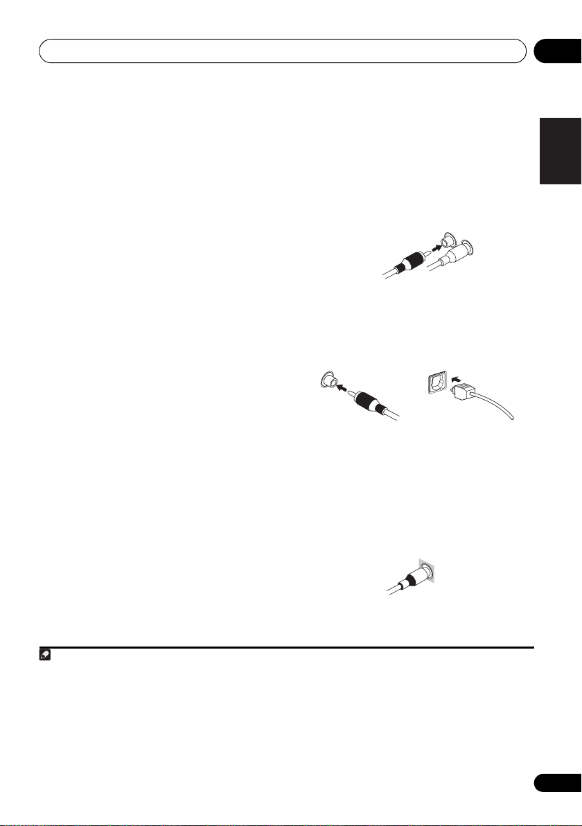
Analog audio cables
Use stereo RCA phono cables to connect
analog audio components. These cables are
typically red and white, and you should
connect the red plugs to R (right) terminals
and white plugs to L (left) terminals.
1
Digital audio cables
Commercially available coaxial digital audio
cables or optical cables should be used to
connect digital components to this receiver.
Coaxial digital audio cable Optical cable
3
Video cables
Standard RCA video cables
These cables are the most common type of
video connection and are used to connect to
the composite video terminals. The yellow
plugs distinguish them from cables for audio.
4
1 • Use a High Speed HDMI® cable. If HDMI cable other than a High Speed HDMI® cable is used, it may not work properly.
• When an HDMI cable with a built-in equalizer is connected, it may not operate properly.
2 Signal transfer is only possible when connected to a compatible component.
3 • HDMI format digital audio transmissions require a longer time to be recognized. Due to this, interruption in the audio may
occur when switching between audio formats or beginning playback.
• Turning on/off the device connected to this unit's HDMI OUT terminal during playback, or disconnecting/connecting the
HDMI cable during playback, may cause noise or interrupted audio.
4 • When connecting optical cables, be careful when inserting the plug not to damage the shutter protecting the optical socket.
• When storing optical cable, coil loosely. The cable may be damaged if bent around sharp corners.
• You can also use a standard RCA video cable for coaxial digital connections.
21
En
Page 22
Connecting your equipment03
Green (Y)
Blue (P
B
)
Red (P
R
)
Component video cables
VIDEO IN
PRP
B
Y
COMPONENT VIDEO IN
HDMI IN
MONITOR OUT
PRP
B
Y
HDMI OUT
COMPONENT VIDEO MONITOR OUT
Terminal for connection with source device
Terminal for connection with TV monitor
Playback
component
TV
The OSD will not
appear.
Video signals can be output.
Component video cables
Use component video cables to get the best
possible color reproduction of your video
source. The color signal of the TV is divided into
the luminance (Y) signal and the color (P
P
R) signals and then output. In this way,
interference between the signals is avoided.
B and
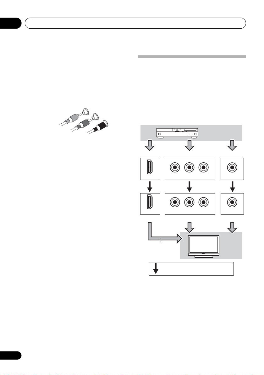
About video outputs connection
This receiver is not loaded with a video
converter. When you use component video
cables or HDMI cables for connecting to the
input device, the same cables should be used
for connecting to the TV.
The signals input from the analog (composite
and component) video inputs of this unit will
not be output from the HDMI OUT.
22
En
Page 23
Connecting your equipment 03
English
Français
Deutsch
Nederlands
Italiano
Español
Note
N
VIDEO IN
HDMI OUT
HDMI IN
DIGITAL AUDIO OUT
OPTICAL
RL
ANALOG AUDIO OUT
MONITOR
OUT
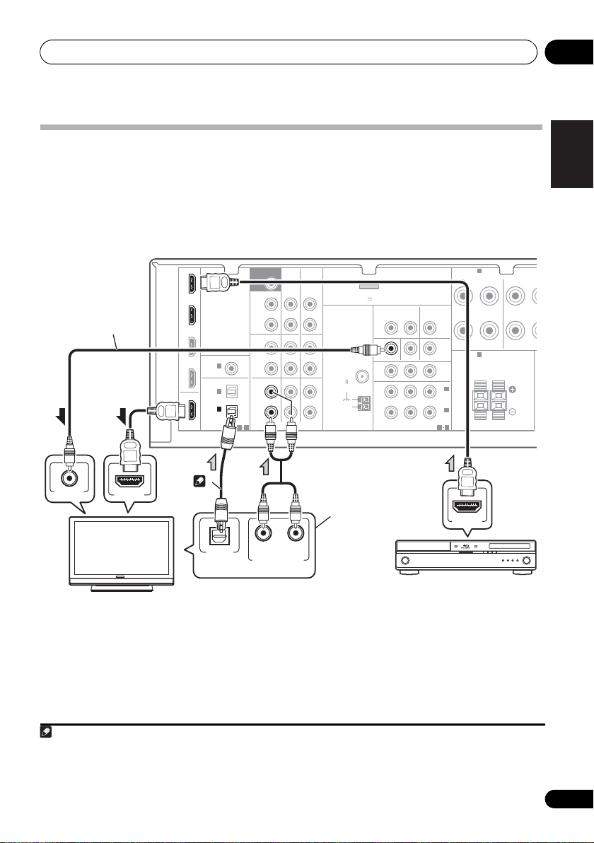
Select one
HDMI/DVI-compatible TV
HDMI/DVI-compatible
Blu-ray disc player
This connection is
required in order to
listen to the sound of
the TV over the receiver.
This connection is
necessary in order to
see the OSD of the
unit on the TV.
2
Connecting a TV and playback components
Connecting using HDMI
If you have an HDMI or DVI (with HDCP) equipped component (Blu-ray disc player, etc.), you can
connect it to this receiver using a commercially available HDMI cable.
• If the receiver is connected to a TV using an HDMI cable, the OSD will not be displayed. Be
sure to use a standard RCA analog video cable to connect.
12
IN BD
DVD
TV/SAT
DVR/VCR
OUT
HDMI
COAXIAL
IN
(CD)
OPTICAL
IN
IN
(
CD-R/TAPE
ASSIGNABLE
1
2
1
)
ASSIGNABLE
1 2
SUBWOOFER
PRE OUT
SURR BACK /
FRONT
HEIGHT
L
(
)
Single
R
PRE OUT
CD
L
IN
R
TV/SAT
L
IN
R
CD-R/TAPE
CD-R/TAPE
DVD BD
AUDIO
DVR/VCR
OUT
DVR/VCR
(
IN
FM
UNBAL
75
IN
AM
LOOP
ADAPTER PORT
OUTPUT 5 V 100 mA MAX
ANTENNA
)
VIDEO
DVR/VCR
OUT IN
MONITOR OUT
PRPBY
COMPONENT VIDEO
TV/SAT
DVD IN BD IN
ASSIGNABLE
IN
MONITOR
OUT
2
IN
(
DVD
1
IN
(BD)
1
2
A
SPEAKERS
FRONT
RL
B
SPEAKERS
RL
)
SURROU
R
1 If you wish to see the OSD screen (for setup, etc.), switch the TV input to analog. (With HDMI input, the OSD will not be
displayed.)
2 If the connection was made using an optical cable, you’ll need to tell the receiver which digital input you connected the TV to
(see Choosing the input signal on page 41).
23
En
Page 24
Connecting your equipment03
Note
N
RL
DIGITAL AUDIO OUT
ANALOG AUDIO OUT
COAXIAL
VIDEO OUT
OPTICAL
DIGITAL AUDIO OUT
OPTICAL
RL
ANALOG AUDIO OUT
VIDEO IN
Select one
TV
DVD player
This connection is
required in order to
listen to the sound of
the TV over the receiver.
Select one
1
2
3
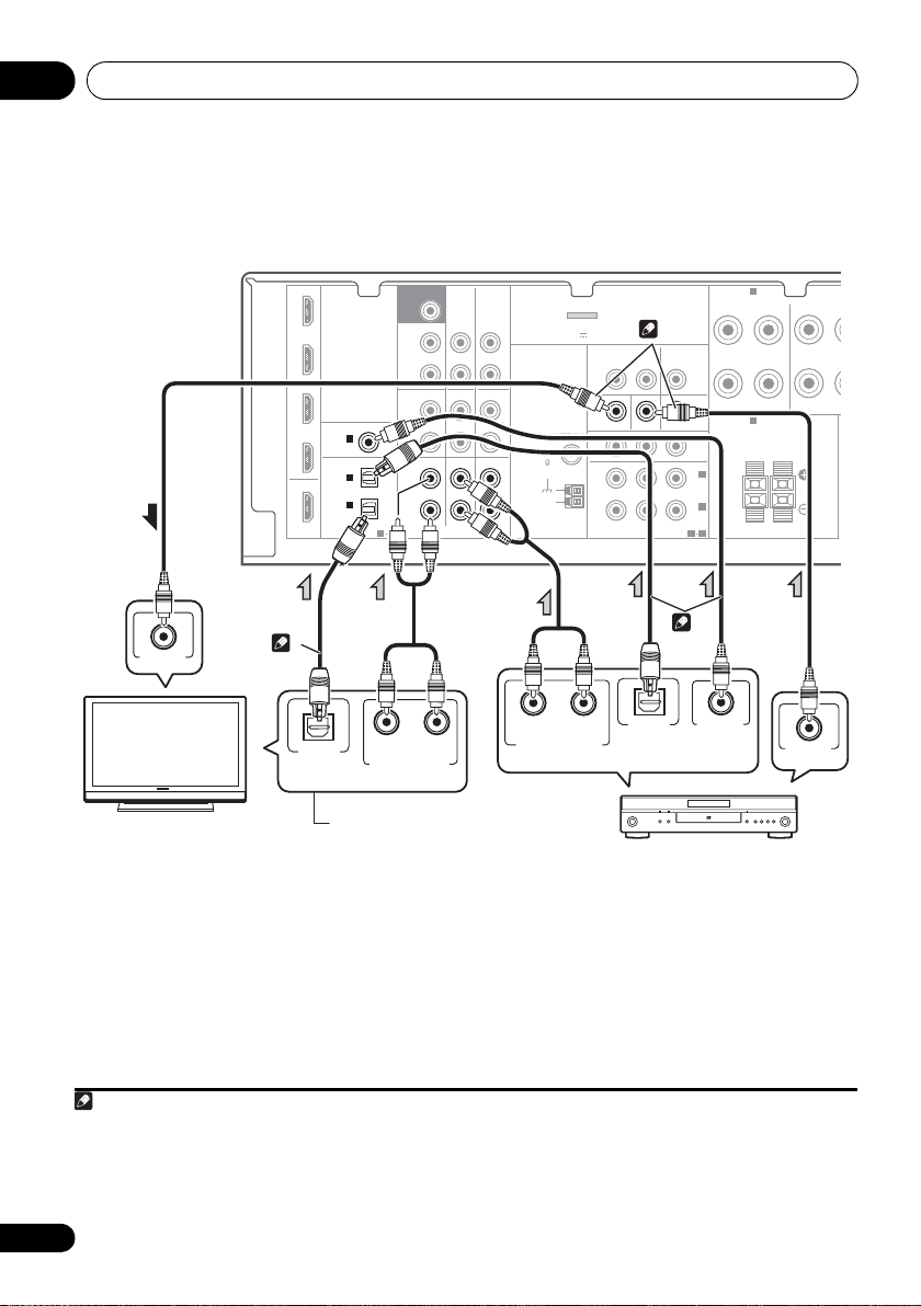
Connecting your component with no HDMI terminal
This diagram shows connections of a TV and DVD player (or other playback component) with no
HDMI terminal to the receiver.
123
IN BD
DVD
TV/SAT
DVR/VCR
OUT
HDMI
COAXIAL
IN
(CD)
OPTICAL
IN
IN
(
CD-R/TAPE
ASSIGNABLE
1
2
1
)
ASSIGNABLE
1 2
SUBWOOFER
PRE OUT
SURR BACK /
FRONT
HEIGHT
L
(
)
Single
R
PRE OUT
CD
L
IN
R
TV/SAT
L
IN
R
CD-R/TAPE
CD-R/TAPE
DVD BD
AUDIO
DVR/VCR
OUT
DVR/VCR
(
IN
FM
UNBAL
75
IN
AM
LOOP
ADAPTER PORT
OUTPUT 5 V 100 mA MAX
ANTENNA
)
VIDEO
DVR/VCR
OUT IN
MONITOR OUT
PRPBY
COMPONENT VIDEO
TV/SAT
DVD IN BD IN
ASSIGNABLE
IN
MONITOR
MONITOR
OUT
OUT
IN
(
DVD
IN
(BD)
1
2
1
2
A
SPEAKERS
FRONT
RL
B
SPEAKERS
RL
)
SURROU
R
1 If the connection was made using an optical cable, you’ll need to tell the receiver which digital input you connected the TV to
(see Choosing the input signal on page 41).
2 If the connection was made using an optical or a coaxial cable, you’ll need to tell the receiver which digital input you connected
the DVD player to (see Choosing the input signal on page 41).
3 If both TV and player has a component video jacks, you can connect these too. See Using the component video jacks on page 26
24
En
for more on this.
Page 25
Connecting your equipment 03
English
Français
Deutsch
Nederlands
Italiano
Español
Note
A
Select one
STB
2
1
Select one
DVR, VCR, LD player, etc.
1
2
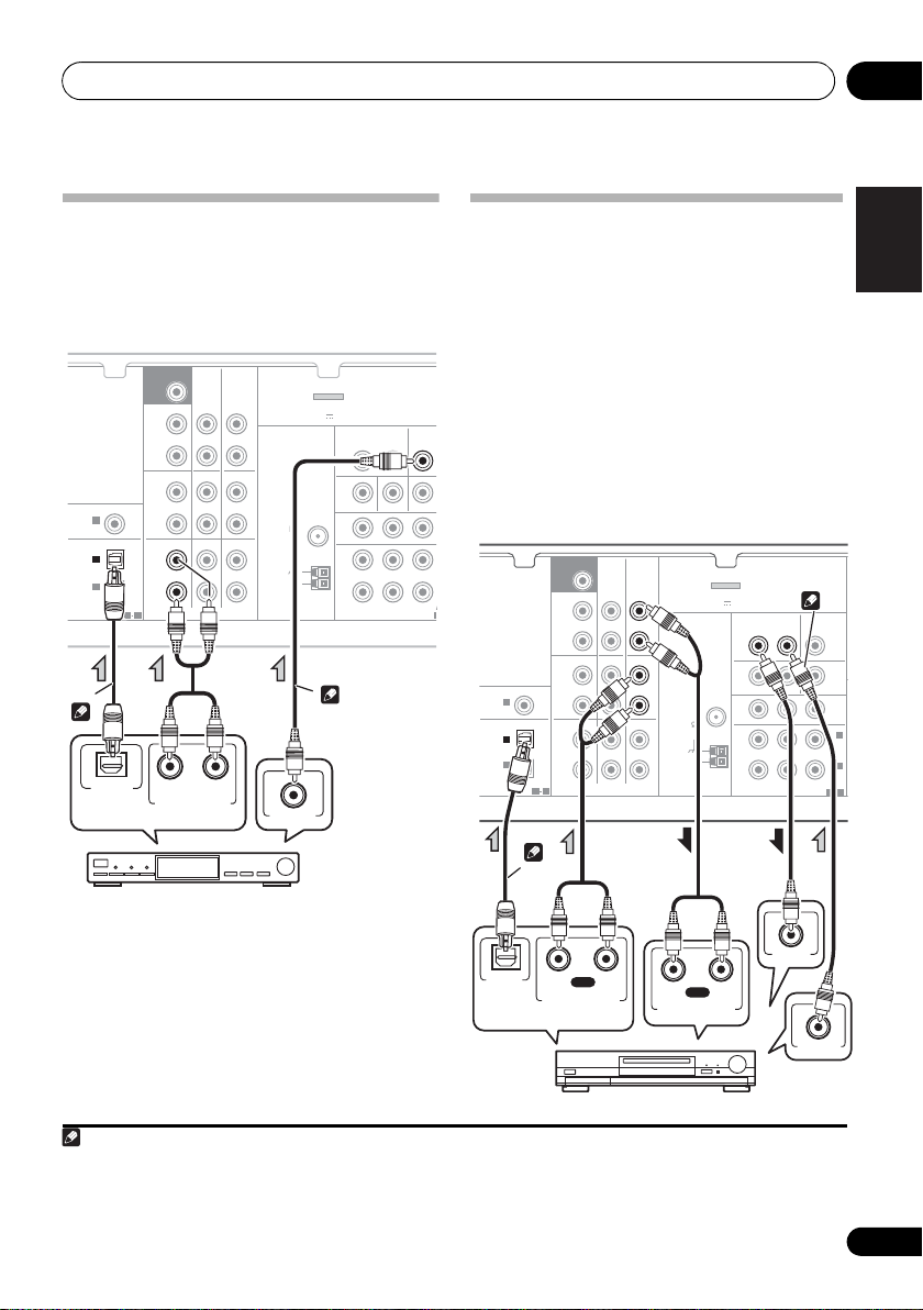
Connecting a satellite receiver or other digital set-top box
Satellite and cable receivers, and terrestrial
digital TV tuners are all examples of so-called
‘set-top boxes’.
COAXIAL
ASSIGNABLE
1
IN
(CD)
OPTICAL
2
IN
1
IN
(
CD-R/TAPE
)
ASSIGNABLE
OPTICAL
DIGITAL AUDIO OUT
1 2
SUBWOOFER
PRE OUT
SURR BACK /
FRONT
HEIGHT
L
(
Single
R
PRE OUT
L
IN
R
L
IN
R
12
DVR/VCR
CD-R/TAPE
)
CD
CD-R/TAPE
DVR/VCR
DVD BD
TV/SAT
AUDIO
RL
ANALOG AUDIO OUT
OUT
IN
IN
VIDEO OUT
ADAPTER PORT
(
OUTPUT 5 V 100 mA MAX
ANTENNA
FM
UNBAL
75
AM
LOOP
)
VIDEO
DVR/VCR
OUT IN
MONITOR OUT
DVD IN BD IN
PRPBY
COMPONENT VIDEO
Connecting an HDD/DVD recorder, VCR and other video sources
This receiver has audio/video inputs and
outputs suitable for connecting analog or
digital video recorders, including HDD/DVD
recorders and VCRs.
• Only the signals that are input to the
TV/SAT
IN
ASSIGN
M
VIDEO IN terminal can be output from the
VIDEO OUT terminal.
• Audio signals that are input through the
digital terminal will not be output from the
analog terminal.
SUBWOOFER
COAXIAL
IN
(CD)
OPTICAL
IN
IN
(
CD-R/TAPE
ASSIGNABLE
1
2
1
)
ASSIGNABLE
1 2
PRE OUT
SURR BACK /
FRONT
HEIGHT
(
Single
PRE OUT
L
R
L
IN
R
L
IN
R
)
CD
TV/SAT
CD-R/TAPE
CD-R/TAPE
DVD BD
AUDIO
DVR/VCR
OUT
DVR/VCR
(
OUTPUT 5 V 100 mA MAX
IN
FM
UNBAL
75
IN
AM
LOOP
ANTENNA
ADAPTER PORT
VIDEO
MONITOR OUT
PRPBY
COMPONENT VIDEO
)
DVR/VCR
OUT IN
DVD IN BD IN
TV/SAT
IN
MONITOR
MONITOR
OUT
OUT
IN
(
DVD
IN
(BD)
ASSIGNABLE
1 2
2
)
1
OPTICAL
DIGITAL
AUDIO OUT
RL
PLAY
ANALOG AUDIO OUT
RL
REC
ANALOG AUDIO IN
1 If the connection was made using an optical cable, you’ll need to tell the receiver which digital input you connected the set-
top box or video component to (see Choosing the input signal on page 41).
2 If the set-top box or video component also has an HDMI or a component video output, you can connect this too. See Connecting
using HDMI on page 23 or Using the component video jacks on page 26 for more on this.
VIDEO IN
VIDEO OUT
25
En
Page 26
Connecting your equipment03
E
BD player
TV
Note
M
T
N
PLAY
R
L
DIGITAL AUDIO OUT
ANALOG AUDIO OUT
COAXIAL
R
L
ANALOG AUDIO IN
REC
OPTICAL
Select one
CD-R, MD, DAT, Tape recorder, etc.
2
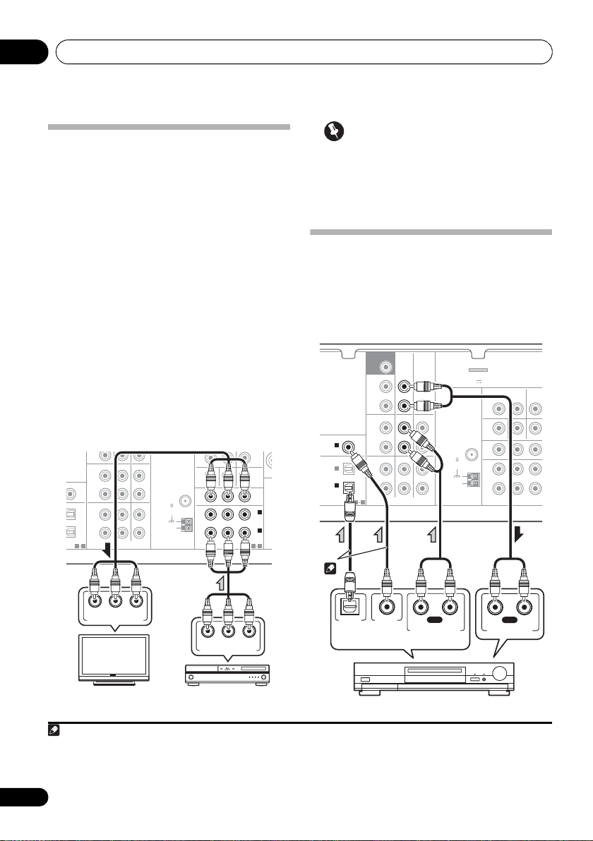
Using the component video jacks
Component video should deliver superior
picture quality when compared to composite
video. A further advantage (if your source and TV
are both compatible) is progressive-scan video,
which delivers a very stable, flicker-free picture.
See the manuals that came with your TV and
source component to check whether they are
compatible with progressive-scan video.
• If necessary, assign the component video
inputs to the input source you’ve connected.
This only needs to be done if you didn’t connect
according to the following defaults:
• COMPONENT VIDEO IN 1 – BD
• COMPONENT VIDEO IN 2 – DVD
See The Input Assign menu on page 46 for
more on this.
• For the audio connection, refer to
Connecting your component with no HDMI
terminal
on page 24.
R
PRE OUT
CD-R/TAPE
DVR/VCR
CD
SIGNABLE
SIGNABLE
1 2
L
IN
R
L
IN
R
TV/SAT
DVD BD
AUDIO
IN
IN
FM
UNBAL
75
AM
LOOP
ANTENNA
MONITOR OUT
PRPBY
COMPONENT VIDEO
DVD IN BD IN
ASSIGNABLE
MONITOR
OUT
IN
(
DVD
IN
(BD)
1 2
SP
2
)
1
Important
• If you connect any source component to
the receiver using a component video
input, you must also have your TV
connected to this receiver’s COMPONENT
VIDEO OUT jacks.
Connecting other audio components
The number and kind of connections depends
on the kind of component you’re connecting.
Follow the steps below to connect a CD-R, MD,
DAT, tape recorder or other audio component.
SUBWOOFER
COAXIAL
IN
(CD)
OPTICAL
IN
IN
(
CD-R/TAPE
ASSIGNABLE
1
2
1
)
ASSIGNABLE
1 2
PRE OUT
SURR BACK /
FRONT
HEIGHT
(
Single
PRE OUT
L
R
L
IN
R
L
IN
R
)
CD
TV/SAT
CD-R/TAPE
CD-R/TAPE
DVD BD
AUDIO
DVR/VCR
OUT
DVR/VCR
(
OUTPUT 5 V 100 mA MAX
IN
FM
UNBAL
75
IN
AM
LOOP
ADAPTER PORT
VIDEO
MONITOR OUT
ANTENNA
COMPONENT VIDEO
)
DVR/VCR
OUT IN
DVD IN BD IN
PRPBY
TV/SA
ASSIG
IN
1
2
RYPB
P
COMPONENT VIDEO IN
1 Note that you must connect digital components to analog audio jacks if you want to record to/from digital components (like
an MD) to/from analog components.
2 If the connection was made using an optical or a coaxial cable, you’ll need to tell the receiver which digital input you connected
the component to (see Choosing the input signal on page 41).
26
En
RYPB
P
COMPONENT VIDEO OUT
Page 27
Connecting your equipment 03
English
Français
Deutsch
Nederlands
Italiano
Español
ANTENNA
FM
UNBAL
75
Ω
AM
LOOP
One-touch
PAL connector
75 Ω coaxial cable
ANTENNA
FM
UNBAL
75
Ω
AM
LOOP
Outdoor
antenna
5 m to 6 m
Indoor antenna
(vinyl-coated wire)
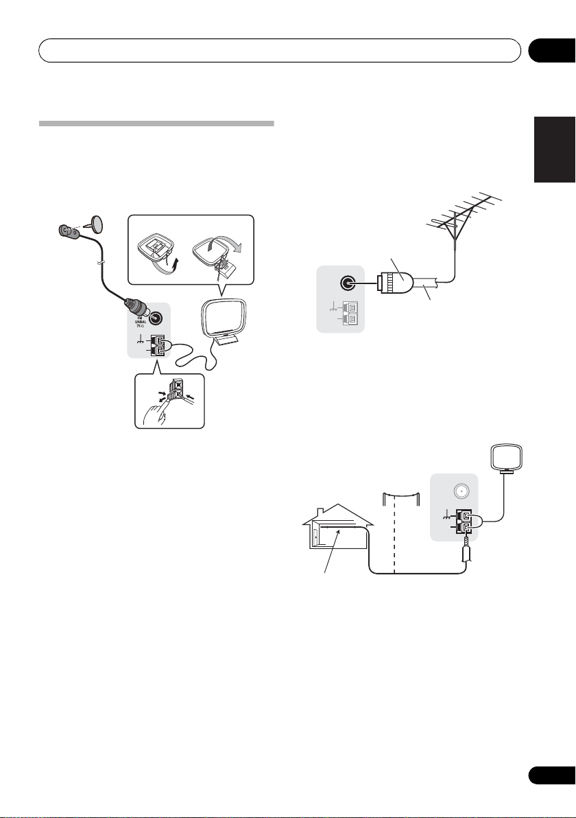
Using external antennas
Connecting antennas
Connect the AM loop antenna and the FM wire
antenna as shown below. To improve reception
and sound quality, connect external antennas
(see Using external antennas below).
fig. a fig. b
To improve FM reception
Use a PAL connector (not supplied) to connect
an external FM antenna.
LOOP
ANTENNA
AM
4
1 Push open the tabs, then insert one wire
fully into each terminal, then release the tabs
to secure the AM antenna wires.
2 Fix the AM loop antenna to the attached
stand.
To fix the stand to the antenna, bend in the
direction indicated by the arrow (fig. a) then
clip the loop onto the stand (fig. b).
3 Place the AM antenna on a flat surface
and in a direction giving the best reception.
4 Connect the FM wire antenna into the FM
antenna socket.
For best results, extend the FM antenna fully
and fix to a wall or door frame. Don’t drape
loosely or leave coiled up.
2
3
To improve AM reception
Connect a 5 m to 6 m length of vinyl-coated
wire to the AM antenna terminal without
1
disconnecting the supplied AM loop antenna.
For the best possible reception, suspend
horizontally outdoors.
27
En
Page 28
Connecting your equipment03
MASTER
VOLUME
MCACC
SETUP MIC
VIDEO INPUT
AUDIOLRVIDEO
iPod
iPhone
USB
CONTROL ON / OFF
LVIDEO
R
AUDIO/VIDEO OUTPUT
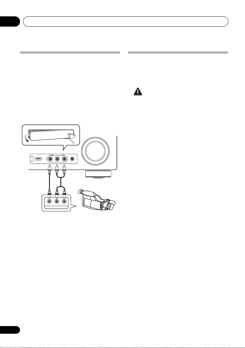
This receiver
Video camera
(etc.)
Connecting to the front panel video terminal
Front video connections are accessed via the
front panel using the INPUT SELECTOR or
VIDEO button on the remote control. There are
standard audio/video jacks. Hook them up the
same way you made the rear panel
connections.
•Push down on the PUSH OPEN tab to
access the front video connections.
Plugging in the receiver
Only plug in after you have connected all your
components to this receiver, including the
speakers.
CAUTION
• Handle the power cord by the plug part. Do
not pull out the plug by tugging the cord,
and never touch the power cord when your
hands are wet, as this could cause a short
circuit or electric shock. Do not place the
unit, a piece of furniture, or other object on
the power cord or pinch the cord in any
other way. Never make a knot in the cord or
tie it with other cables. The power cords
should be routed so that they are not likely
to be stepped on. A damaged power cord
can cause a fire or give you an electric
shock. Check the power cord once in a
while. If you find it damaged, ask your
nearest Pioneer authorized independent
service company for a replacement.
• Do not use any power cord other than the
one supplied with this unit.
• Do not use the supplied power cord for any
purpose other than that described below.
• The receiver should be disconnected by
removing the mains plug from the wall
socket when not in regular use, e.g., when
on vacation.
1 Plug the supplied power cord into the AC
IN socket on the back of the receiver.
2 Plug the other end into a power outlet.
28
En
Page 29
Basic Setup 04
English
Français
Deutsch
Nederlands
Italiano
Español
ENTER
RETURN
AUDIO
PARAMETER
TUNER EDIT
TOOLS
MASTER
VOLUME
iPod CTRL
BAND
MENU
HOME
MENU
SETUP
TOP
MENU
T
U
N
E
T
U
N
E
P
R
E
S
E
T
P
R
E
S
E
T
MASTER
VOLUME
MCACC
SETUP MIC
VIDEO INPUT
AUDIOLRVIDEO
iPod
iPhone
USB
CONTROL ON / OFF
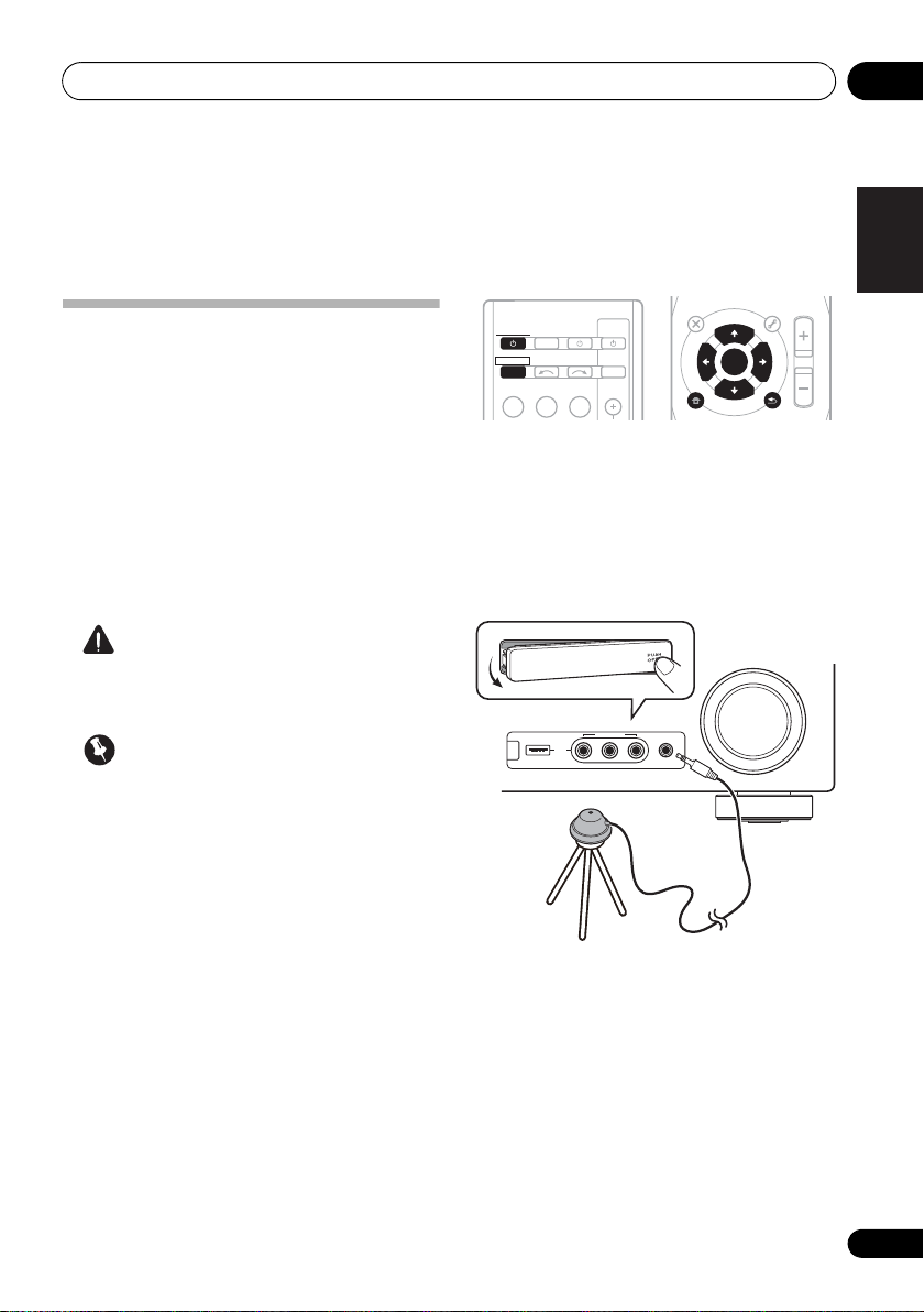
Tripod
Microphone
Chapter 4:
Basic Setup
Automatically setting up for surround sound (MCACC)
The Auto Multi-Channel Acoustic Calibration
(MCACC) setup measures the acoustic
characteristics of your listening area, taking
into account ambient noise, speaker size and
distance, and tests for both channel delay and
channel level. After you have set up the
microphone provided with your system, the
receiver uses the information from a series of
test tones to optimize the speaker settings and
equalization for your particular room.
CAUTION
• The test tones used in the Auto MCACC
Setup are output at high volume.
Important
• The OSD will not appear if you have
connected using the HDMI output to your
TV. Use component or composite
connections for system setup.
• The Auto MCACC Setup will overwrite any
existing speaker settings you’ve made.
• Before using the Auto MCACC Setup, the
iPod USB function should not be selected
as an input source.
• If you connected either the surround back
speaker or the front height speaker, make
sure that the Pre Out setting is correctly set
before performing the Auto MCACC Setup
(see page 47). (Here is an explanation
using the OSD screen for a surround back
speaker connection.)
RECEIVER
RECEIVER
BD DVD
INPUT SELECT
TV
CONTROL
SOURCESLEEP
INPUT
TV
1 Switch on the receiver and your TV.
Switch the TV input so that it connects to the
receiver in analog.
2 Connect the microphone to the MCACC
SETUP MIC jack on the front panel.
Make sure there are no obstacles between the
speakers and the microphone.
If you have a tripod, use it to place the
microphone so that it’s about ear level at your
normal listening position. Otherwise, place the
microphone at ear level using a table or a chair.
29
En
Page 30
Basic Setup04
Note
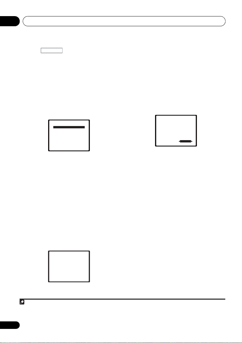
System Setup
1.Auto MCACC
2.Manual SP Setup
3.Input Assign
4.Pre Out Setting
Return
3 Press on the remote control,
then press the
RECEIVER
SETUP
button.
An on-screen display (OSD) appears on your
TV. Use /// and ENTER on the remote
control to navigate through the screens and
select menu items. Press RETURN to exit the
current menu.
• Press SETUP at any time to exit the System
Setup menu.
4 Select ‘Auto MCACC’ from the System
Setup menu then press ENTER.
1
2
Try to be as quiet as possible after pressing
ENTER. The system outputs a series of test
tones to establish the ambient noise level.
5 Follow the instructions on-screen.
• Make sure the microphone is connected.
• Make sure the subwoofer is on and the
volume is turned up.
• See below for notes regarding background
noise and other possible interference.
6 Wait for the test tones to finish.
A progress report is displayed on-screen while
the receiver outputs test tones to determine the
speakers present in your setup. Try to be as
quiet as possible while it’s doing this.
1.Auto MCACC
Now Analyzing
Environment Check
Ambient Noise
Speaker YES/NO
Return
• For correct speaker settings, do not adjust
the volume during the test tones.
7 Confirm the speaker configuration.
The configuration shown on-screen should
reflect the actual speakers you have.
• With error messages (such as Too much
ambient noise) select RETRY after
checking for ambient noise (see Other
problems when using the Auto MCACC
Setup on page 31).
1.Auto MCACC
Check!
[ YES ]
Front
[ YES ]
Center
[ YES ]
Surr
[YESx2]
Surr. Back
[ YES ]
Subwoofer
10:Next
OK
Return
If the speaker configuration displayed isn’t
correct, use / to select the speaker and
/ to change the setting. When you’re
finished, go to the next step.
If you see an error message (ERR) in the right
side column, there may be a problem with the
speaker connection. If selecting RETRY
doesn’t fix the problem, turn off the power and
check the speaker connections.
8 Make sure ‘OK’ is selected, then press
ENTER.
If the screen in step 7 is left untouched for 10
seconds and the ENTER button is not pressed
in step 8, the Auto MCACC setup will start
automatically as shown below.
30
En
1 The screensaver automatically starts after three minutes of inactivity. If you cancel the Auto MCACC Setup at any time, the
receiver automatically exits and no settings will be made.
2 MIC IN blinks when the microphone is not connected to MCACC SETUP MIC.
Page 31

Basic Setup 04
English
Français
Deutsch
Nederlands
Italiano
Español
Note
1.Auto MCACC
Now Analyzing
Surround Analyzing
Speaker System
Speaker Distance
Channel Level
Acoustic Cal EQ
Return
A progress report is displayed on-screen while
the receiver outputs more test tones to
determine the optimum receiver settings for
channel level, speaker distance, and Acoustic
Calibration EQ.
Again, try to be as quiet as possible while this
is happening. It may take 1 to 3 minutes.
9 The Auto MCACC Setup has finished!
You return to the System Setup menu.
The settings made in the Auto MCACC Setup
should give you excellent surround sound from
your system, but it is also possible to adjust
these settings manually using the System
Setup menu (starting on page 42).
Other problems when using the Auto MCACC Setup
If the room environment is not optimal for the
Auto MCACC Setup (too much background
noise, echo off the walls, obstacles blocking
the speakers from the microphone) the final
settings may be incorrect. Check for household
appliances (air conditioner, fridge, fan, etc.),
that may be affecting the environment and
switch them off if necessary. If there are any
instructions showing in the front panel display,
please follow them.
• Some older TVs may interfere with the
operation of the microphone. If this seems
to be happening, switch off the TV when
doing the Auto MCACC Setup.
1
1 • Depending on the characteristics of your room, sometimes identical speakers with cone sizes of around 12 cm will end up
with different size settings. You can correct the setting manually using the Speaker Setting on page 43.
• The subwoofer distance setting may be farther than the actual distance from the listening position. This setting should be
accurate (taking delay and room characteristics into account) and generally does not need to be changed.
31
En
Page 32

Listening to your system05
Note
Chapter 5:
Listening to your system
Important
• The listening modes and many features
described in this section may not be
available depending on the current source,
settings and status of the receiver.
Basic playback
Here are the basic instructions for playing a
source (such as a DVD disc) with your home
theater system.
1 Switch on your system components and
receiver.
Start by switching on the playback component
(for example a DVD player), your TV
subwoofer (if you have one), then the receiver
(press RECEIVER).
• Make sure the setup microphone is
disconnected.
2 Select the input function you want to
play.
You can use the input function buttons on the
remote control, INPUT SELECT, or the front
panel INPUT SELECTOR dial.
1
and
2
3 Press AUTO/DIRECT to select ‘AUTO
SURROUND’ and start playback of the source.
If you’re playing a Dolby Digital or DTS
surround sound DVD disc, you should hear
surround sound. If you are playing a stereo
source, you will only hear sound from the front
left/right speakers in the default listening
mode.
It is possible to check on the front panel display
whether or not surround sound playback is
being performed properly.
When using a surround back speaker,
2D+PLIIx is displayed when playing Dolby
Digital 5.1-channel signals, and DTS+NEO:6 is
displayed when playing DTS 5.1-channel
signals.
When not using a surround back speaker, 2D
is displayed when playing Dolby Digital
signals.
If the display does not correspond to the input
signal and listening mode, check the
connections and settings.
4 Use the volume control to adjust the
volume level.
Turn down the volume of your TV so that all
sound is coming from the speakers connected
to this receiver.
3
1 Make sure that the TV’s video input is set to this receiver (for example, if you connected this receiver to the VIDEO jacks on
your TV, make sure that the VIDEO input is now selected).
2 If you need to manually switch the input signal type press SIGNAL SEL (page 41).
3 • You may need to check the digital audio output settings on your DVD player or digital satellite receiver. It should be set to
output Dolby Digital, DTS and 88.2 kHz / 96 kHz PCM (2 channel) audio, and if there is an MPEG audio option, set this to convert
the MPEG audio to PCM.
• Depending on your DVD player or source discs, you may only get digital 2 channel stereo and analog sound. In this case, the
receiver must be set to a multichannel listening mode if you want multichannel surround sound.
32
En
Page 33

Listening to your system 05
English
Français
Deutsch
Nederlands
Italiano
Español
Note
• While listening to a source, press
Auto playback
The simplest, most direct listening option is the
Auto Surround feature. With this, the receiver
automatically detects what kind of source
you’re playing and selects multichannel or
stereo playback as necessary.
STEREO/
AUTO/
A.L.C.
DIRECT
• While listening to a source, press
AUTO/DIRECT
2
for auto playback of a
STANDARD
1
BD MENU
ADV SURR
source.
Press repeatedly until AUTO SURROUND
shows briefly in the display (it will then show
the decoding or playback format). Check the
digital format indicators in the display to see
how the source is being processed.
Listening in surround sound
Using this receiver, you can listen to any source
in surround sound. However, the options
available will depend on your speaker setup and
the type of source you’re listening to.
The following modes provide basic surround
sound for stereo and multichannel sources.
AUTO/
DIRECT
STEREO/
A.L.C.
STANDARD
BD MENU
ADV SURR
STANDARD.
If the source is Dolby Digital, DTS, or Dolby
Surround encoded, the proper decoding
format will automatically be selected and
shows in the display.
When the surround back and front height
speaker are not connected.
With two channel sources, you can select from:
• DOLBY PLII MOVIE – Up to 5.1 channel
sound, especially suited to movie sources
• DOLBY PLII MUSIC
3
– Up to 5.1 channel
sound, especially suited to music sources
• DOLBY PLII GAME – Up to 5.1 channel
sound, especially suited for video games
• NEO:6 CINEMA – Up to 5.1 channel
sound, especially suited to movie sources
• NEO:6 MUSIC – Up to 5.1 channel sound,
especially suited to music sources
• DOLBY PRO LOGIC – 4.1 channel
surround sound
When the front height speaker is connected.
With two channel sources, you can select from:
• DOLBY PLII MOVIE – See above
• DOLBY PLII MUSIC – See above
• DOLBY PLII GAME – See above
• DOLBY PLIIz HEIGHT – Up to 7.1 channel
sound
5
• NEO:6 CINEMA – See above
• NEO:6 MUSIC – See above
• DOLBY PRO LOGIC – See above
• Straight Decode – Plays back without the
DOLBY PLII, DOLBY PLIIz HEIGHT and
NEO:6 effects.
4
1 Stereo surround (matrix) formats are decoded accordingly using NEO:6 CINEMA or DOLBY PLIIx MOVIE (see Listening in
surround sound above for more on these decoding formats).
2 For more options using this button, see Using Stream Direct on page 36.
3 When listening to 2-channel sources in DOLBY PLII MUSIC mode, there are three further parameters you can adjust:
C.WIDTH, DIMEN., and PNRM.. See Setting the Audio options on page 38 to adjust them.
4 When listening to 2-channel sources in NEO:6 CINEMA or NEO:6 MUSIC mode, you can also adjust the C.IMG effect (see
Setting the Audio options on page 38).
5 When listening to 2-channel sources in DOLBY PLIIz HEIGHT mode, you can also adjust the H.GAIN effect (see Setting the
Audio options on page 38).
33
En
Page 34

Listening to your system05
Note
With multichannel sources, you can select
from:
• DOLBY PLIIz HEIGHT – Up to 7.1 channel
sound
1
• Straight Decode – Plays back without the
DOLBY PLIIz HEIGHT effects.
When the surround back speaker is
connected.
2
If you connected surround back speakers, see
also Using surround back channel processing
on page 37.
With two channel sources, you can select from:
• DOLBY PLIIx MOVIE – Up to 7.1 channel
sound, especially suited to movie sources
• DOLBY PLIIx MUSIC – Up to 7.1 channel
sound, especially suited to music sources
• DOLBY PLIIx GAME – Up to 7.1 channel
sound, especially suited to video games
• NEO:6 CINEMA – Up to 6.1 channel sound,
especially suited to movie sources
• NEO:6 MUSIC – Up to 6.1 channel sound,
especially suited to music sources
4
• DOLBY PRO LOGIC – 4.1 channel
surround sound (sound from the surround
speakers is mono)
With multichannel sources, if you have
connected surround back speaker(s) and have
selected SB ON, you can select (according to
format):
• DOLBY PLIIx MOVIE – See above (only
available when you’re using two surround
back speakers)
• DOLBY PLIIx MUSIC – See above
• DOLBY DIGITAL EX – Creates surround
back channel sound for 5.1 channel
sources and provides pure decoding for
6.1 channel sources (like Dolby Digital
Surround EX)
• DTS-ES – Allows you to hear 6.1 channel
playback with DTS-ES encoded sources
• DTS NEO:6 –
Allows you to hear 6.1 channel
playback with DTS encoded sources
Using the Advanced surround effects
The Advanced surround feature creates a
variety of surround effects. Try different modes
with various soundtracks to see which you like.
STANDARD
BD MENU
ADV SURR
STEREO/
AUTO/
A.L.C.
3
DIRECT
• Press ADV SURR repeatedly to select a
listening mode.
• ACTION – Designed for action movies with
dynamic soundtracks.
• DRAMA – Designed for movies with lots of
dialog.
• ENT.SHOW –
Suitable for musical sources.
• ADVANCED GAME – Suitable for video
games.
• SPORTS – Suitable for sports programs.
• CLASSICAL – Gives a large concert halltype sound.
• ROCK/POP – Creates a live concert sound
for rock and/or pop music.
• UNPLUGGED – Suitable for acoustic
music sources.
• EXT.STEREO –
Gives multichannel sound to
a stereo source, using all of your speakers.
1 When listening to 2-channel sources in DOLBY PLIIz HEIGHT mode, you can also adjust the H.GAIN effect (see Setting the
Audio options on page 38).
2 • If surround back channel processing (page 37) is switched off, or the surround back speakers are set to NO, DOLBY PLIIx
becomes DOLBY PLII (5.1 channel sound).
• In modes that give 6.1 channel sound, the same signal is heard from both surround back speakers.
3 When listening to 2-channel sources in DOLBY PLIIx MUSIC mode, there are three further parameters you can adjust:
C.WIDTH, DIMEN., and PNRM.. See Setting the Audio options on page 38 to adjust them.
4 When listening to 2-channel sources in NEO:6 CINEMA or NEO:6 MUSIC mode, you can also adjust the C.IMG effect
(see Setting the Audio options on page 38).
34
En
Page 35

Listening to your system 05
English
Français
Deutsch
Nederlands
Italiano
Español
BD MENU
STANDARD
ADV SURR
AUTO/
DIRECT
STEREO/
A.L.C.
F.S.S.ADVANCE
position
Front left
speaker
Front right
speaker
Listening in stereo
When you select STEREO you will hear the
source through just the front left and right
speakers (and possibly your subwoofer
depending on your speaker settings). Dolby
Digital and DTS multichannel sources are
downmixed to stereo.
In the Auto level control stereo mode (ALC),
this unit equalizes playback sound levels if
each sound level varies with the music source
recorded in a portable audio player.
AUTO/
STEREO/
DIRECT
A.L.C.
• While listening to a source, press
STEREO/A.L.C. for stereo playback.
Press repeatedly to switch between:
• STEREO – The audio is heard with your
surround settings and you can still use the
Midnight, Loudness, Phase Control, Sound
Retriever and Tone functions.
• ALC – Listening in Auto level control stereo
mode.
• F.S.S.ADVANCE – See Using Front Stage
Surround Advance below for more on this.
STANDARD
BD MENU
ADV SURR
Using Front Stage Surround Advance
The Front Stage Surround Advance function
allows you to create natural surround sound
effects using just the front speakers and the
subwoofer.
• While listening to a source, press
STEREO/A.L.C. to select Front Stage
Surround Advance modes.
• STEREO – See Listening in stereo above for
more on this.
• ALC – See Listening in stereo above for
more on this.
• F.S.S.ADVANCE – Use to provide a rich
surround sound effect directed to the
center of where the front left and right
speakers sound projection area
converges.
35
En
Page 36

Listening to your system05
Note
BD MENU
STANDARD
ADV SURR
STEREO/
A.L.C.
AUTO/
DIRECT
ADAPTER i Pod USB
VIDEO
TUNER
S.RETRIEVER
SIGNAL SEL
VOL
Using Stream Direct
Use the Stream Direct modes when you want
to hear the truest possible reproduction of a
source. All unnecessary signal processing is
bypassed.
• While listening to a source, press AUTO/
DIRECT to select Stream Direct mode.
• AUTO SURROUND – See Auto playback on
page 33.
• DIRECT – Sources are heard according to
the settings made in the Surround Setup
(speaker setting, channel level, speaker
distance), as well as with dual mono
settings.
1
You will hear sources according
to the number of channels in the signal.
• PURE DIRECT – Analog and PCM sources
are heard without any digital processing.
Using the Sound Retriever
When audio data is removed during the
compression process, sound quality often
suffers from an uneven sound image. The
Sound Retriever feature employs new DSP
technology that helps bring CD quality sound
back to compressed 2-channel audio by
restoring sound pressure and smoothing
jagged artifacts left over after compression.
2
Better sound using Phase Control
This receiver’s Phase Control feature uses
phase correction measures to make sure your
sound source arrives at the listening position in
phase, preventing unwanted distortion and/or
coloring of the sound (see illustration below).
During multichannel playback, LFE (LowFrequency Effects) signals as well as lowfrequency signals in each channel are
assigned to the subwoofer or other the
subwoofer and the most appropriate speaker.
At least in theory, however, this type of
processing involves a group delay that varies
with frequency, resulting in phase distortion
where the low-frequency sound is delayed or
muffled by the conflict with other channels.
With the Phase Control mode switched on, this
receiver can reproduce powerful bass sound
without deteriorating the quality of the original
sound (see illustration below).
P
H
A
S
E
C
O
N
T
R
O
L
O
F
F
P
H
A
S
E
C
O
N
T
R
O
L
O
N
Sound
source
Sound
source
Front speaker
Subwoofer
Front speaker
Subwoofer
Listening
position
Listening
position
?
•Press
S.RETRIEVER
to switch the sound
retriever on or off.
1In the DIRECT mode, Phase Control, Acoustic Calibration EQ, Sound Delay, Auto Delay, LFE Attenuate and Center image
functions are available.
2 The Sound Retriever is only applicable to 2-channel sources.
36
En
Page 37

Listening to your system 05
English
Français
Deutsch
Nederlands
Italiano
Español
Note
INPUT SELECT
SOURCESLEEP
TV
CONTROL
INPUT
RECEIVER
RECEIVER
DIMMER
1
4
7
MIDNIGHT
HDD
2
5
8
SPEAKERS
LEV
LEV
SB CH
DISP
EQ
PHASE
DVD
3
6
9
CH
CH
CH SELECT
VCR
SHIFT
RECEIVER
DIMMER
1
4
7
MIDNIGHT
HDD
2
5
8
SPEAKERS
LEV
LEV
SB CH
DISP
EQ
PHASE
DVD
3
6
9
CH
CH
CH SELECT
VCR
SHIFT
RECEIVER
DIMMER
1
4
7
MIDNIGHT
HDD
2
5
8
SPEAKERS
LEV
LEV
SB CH
DISP
EQ
PHASE
DVD
3
6
9
CH
CH
CH SELECT
VCR
SHIFT
Phase Control technology provides coherent
sound reproduction through the use of phase
matching
1
for an optimal sound image at your
listening position. The default setting is on and
we recommend leaving Phase Control
switched on for all sound sources.
• Press , then press
PHASE
switch the Phase Control on or off.
Listening with Acoustic Calibration EQ
You can listen to sources using the Acoustic
Calibration Equalization set in Automatically
setting up for surround sound (MCACC) on
page 29. Refer to these pages for more on
Acoustic Calibration Equalization.
RECEIVER
RECEIVER
INPUT SELECT
• While listening to a source, press
Acoustic Calibration EQ on or off.
The MCACC indicator on the front panel lights
when Acoustic Calibration EQ is active.
TV
CONTROL
SOURCESLEEP
INPUT
, then press EQ to switch the
to
2
Using surround back channel processing
You can have the receiver automatically use
6.1 or 7.1 decoding for 6.1 encoded sources
(for example, Dolby Digital EX or DTS-ES), or
you can choose to always use 6.1 or 7.1
decoding (for example, with 5.1 encoded
material). With 5.1 encoded sources, a
surround back channel will be generated, but
the material may sound better in the 5.1
format for which it was originally encoded (in
which case, you can simply switch surround
back channel processing off).
• With a 7.1-channel surround system,
audio signals that have undergone matrix
decoding processing through surround
back channel processing to which the Up
Mix function is added are output from the
surround back speakers.
RECEIVER
RECEIVER
INPUT SELECT
• Press , then press SB CH
repeatedly to cycle the surround back
channel options.
Each press cycles through the options as
follows:
• SB ON –
generating the surround back component
from the surround component is turned on.
TV
CONTROL
SOURCESLEEP
INPUT
RECEIVER
Matrix decoding processing for
1 Phase matching is a very important factor in achieving proper sound reproduction. If two waveforms are ‘in phase’, they crest
and trough together, resulting in increased amplitude, clarity and presence of the sound signal. If a crest of a wave meets a
trough (as shown in the upper section of the diagram above) then the sound will be ‘out of phase’ and an unreliable sound
image will be produced.
• If your subwoofer has a phase control switch, set it to the plus (+) sign (or 0°). However, the effect you can actually feel when
PHASE CONTROL is set to ON on this receiver depends on the type of your subwoofer. Set your subwoofer to maximize the
effect. It is also recommended you try changing the orientation or the place of your subwoofer.
• Set the built-in lowpass filter switch of your subwoofer to OFF. If this cannot be done on your subwoofer, set the cutoff
frequency to a higher value.
• If the speaker distance is not properly set, you may not have a maximized PHASE CONTROL effect.
• The PHASE CONTROL mode cannot be set to ON in the following cases:
– When the PURE DIRECT mode is switched on.
– When the headphones are connected.
2 You can’t use Acoustic Calibration EQ with Stream Direct mode and it has no effect with headphones.
37
En
Page 38

Listening to your system05
Note
C
SW
L R
SL SR
SBL SBR SBL SBR
C
SW
L R
SL SR
UP MIX OFF UP MIX ON
ENTER
RETURN
AUDIO
PARAMETER
TUNER EDIT
TOOLS
MASTER
VOLUME
iPod CTRL
BAND
MENU
HOME
MENU
SETUP
TOP
MENU
T
U
N
E
T
U
N
E
P
R
E
S
E
T
P
R
E
S
E
T
RECEIVER
• SB AUTO – Matrix decoding processing for
generating the surround back component
from the surround component is switched
automatically. Matrix decoding processing
is only performed when surround back
channel signals are detected in the input
signals.
• SB OFF – Matrix decoding processing for
generating the surround back component
from the surround component is turned
off.
Setting the Up Mix function
In a 7.1-channel surround system with
surround speakers placed directly at the sides
of the listening position, the surround sound of
5.1-channel sources is heard from the side. The
Up Mix function mixes the sound of the
surround speakers with the surround back
speakers so that the surround sound is heard
from diagonally to the rear as it should be.
• Using the Up Mix function is effective when
the speakers in the 7.1-channel surround
system are set up as recommended in the
example on page 16.
• Depending on the positions of the speakers
and the sound source, in some cases it
may not be possible to achieve good
results. In this case, set the setting to OFF.
1 Switch the receiver into standby.
38
En
1• Set to ON regardless of this setting when playing DTS-HD signals.
• May automatically be set to OFF even when set to ON, depending on the input signal and listening mode.
2 While holding down the
the front panel, and hold the
ON
for about two seconds.
PRESET
STANDBY/
on
UP MIX: OFF appears and the Up Mix function
turns off. If you want to turn this function on,
perform steps 1 and 2 again.
•When set to ON, the (Up Mix) indicator
on the front panel lights.
Setting the Audio options
There are a number of additional sound
settings you can make using the AUDIO
PARAMETER menu. The defaults, if not stated,
are listed in bold.
Important
• Note that if a setting doesn’t appear
1
in the AUDIO PARAMETER menu, it is
unavailable due to the current source,
settings and status of the receiver.
RECEIVER
RECEIVER
BD DVD
INPUT SELECT
TV
CONTROL
SOURCESLEEP
INPUT
TV
1 Press on the remote control,
then press
2Use
AUDIO PARAMETER
/
to select the setting you want to
button.
adjust.
Depending on the current status/mode of the
receiver, certain options may not be able to be
selected. Check the table below for notes on
this.
3Use
/
to set it as necessary.
See the table below for the options available for
each setting.
4Press
RETURN
to confirm and exit the
menu.
Page 39

Listening to your system 05
English
Français
Deutsch
Nederlands
Italiano
Español
Setting What it does Option(s)
EQ
(Acoustic Calibration
EQ)
S.DELAY
(Sound Delay)
MIDNIGHT
LOUDNESS
b
S.RTV
(Sound Retriever)
DUAL MONO
DRC
(Dynamic Range
Control)
LFE ATT
(LFE Attenuate)
SACD G.
(SACD Gain)
a
a
d
f
Switches on/off the effect of Acoustic Calibration EQ. ON
OFF
Some monitors have a slight delay when showing video, so
the soundtrack will be slightly out of sync with the picture.
By adding a bit of delay, you can adjust the sound to match
the presentation of the video.
Allows you to hear effective surround sound of movies at
low volumes.
Used to get good bass and treble from music sources at
low volumes.
When audio data is removed during the WMA/MP3
compression process, sound quality often suffers from an
uneven sound image. The Sound Retriever feature employs
new DSP technology that helps bring CD quality sound
back to compressed 2-channel audio by restoring sound
pressure and smoothing jagged artifacts left over after
compression.
Specifies how dual mono encoded Dolby Digital
soundtracks should be played.
Adjusts the level of dynamic range for movie soundtracks
optimized for Dolby Digital, DTS, Dolby Digital Plus, Dolby
TrueHD, DTS-HD and DTS-HD Master Audio (you may
need to use this feature when listening to surround sound
at low volumes).
Some Dolby Digital and DTS audio sources include ultralow bass tones. Set the LFE attenuator as necessary to
prevent the ultra-low bass tones from distorting the sound
from the speakers.
The LFE is not limited when set to 0 dB, which is the
recommended value. When set to –15 dB, the LFE is
limited by the respective degree. When OFF is selected, no
sound is output from the LFE channel.
Brings out detail in SACDs by maximizing the dynamic
range (during digital processing).
c
0.0 to 9.0 (frames)
1 second = 25 frames
(PAL)
Default: 0.0
M/L OFF
MIDNIGHT
LOUDNESS
OFF
ON
CH1 –
Channel 1 is heard only
CH2 –
Channel 2 is heard only
CH1 CH2 –
Both channels heard
from front speakers
AUTO
MAX
MID
OFF
0 (0 dB)
5 (–5 dB)
10 (–10 dB)
15 (–15 dB)
20 (–20 dB)
** (OFF)
0 (dB)
+6 (dB)
e
39
En
Page 40

Listening to your system05
Setting What it does Option(s)
HDMI
(HDMI Audio)
A.DLY
(Auto Delay)
C.WIDTH
(Center Width)
(Applicable only when
using a center speaker)
DIMEN.
(Dimension)
PNRM.
(Panorama)
C.IMG
(Center image)
(Applicable only when
using a center speaker)
H.GAIN
(Height Gain)
h
h
h
i
a. You can change the MIDNIGHT/LOUDNESS options at any time by using MIDNIGHT button.
b. You can change the Sound Retriever feature at any time by using S.RETRIEVER button.
c. WMA and MP3 playback available only via iPod/USB input.
d. This setting works only with dual mono encoded Dolby Digital and DTS soundtracks.
e. The initial set AUTO is only available for Dolby TrueHD signals. Select MAX or MID for signals other than
Dolby TrueHD.
f. You shouldn’t have any problems using this with most SACD discs, but if the sound distorts, it is best to
switch the gain setting back to 0 dB.
g. This feature is only available when the connected display supports the automatic audio/video synchronizing
capability (‘lip-sync’) for HDMI. If you find the automatically set delay time unsuitable, set A.DLY to OFF and
adjust the delay time manually. For more details about the lip-sync feature of your display, contact the
manufacturer directly.
h. Only available with 2-channel sources in DOLBY PLII MUSIC mode.
i. Only when listening to 2-channel sources in NEO:6 CINEMA and NEO:6 MUSIC mode.
Specifies the routing of the HDMI audio signal out of this
receiver (amp) or through to a TV. When THRU is selected,
no sound is output from this receiver.
This feature automatically corrects the audio -to-video delay
between components connected with an HDMI cable. The
audio delay time is set depending on the operational status
of the display connected with an HDMI cable. The video
delay time is automatically adj ust ed according to the audio
delay time.
g
Spreads the center channel between the front right an d left
speakers, making it sound wider (higher settings) or
narrower (lower settings).
Adjusts the surround sound balance from front to back,
making the sound more distant (minus settings), or more
forward (positive settings).
Extends the front stereo image to include surround
speakers for a ‘wraparound’ effect.
Adjust the center image to create a wider stereo effect with
vocals. Adjust the effect from 0 (all center channel sent to
front right and left speakers) to 10 (center channel sent to
the center speaker only).
Adjusts the output from the front height speaker when
listening in DOLBY PLIIz HEIGHT mode. If set to H, the
sound from the top will be more emphasized.
AMP
THRU
OFF
ON
0 to 7
Default: 3
–3 to +3
Default: 0
OFF
ON
0 to 10
Default: 3
(NEO:6 MUSIC),
10 (NEO:6 CINEMA)
L (Low)
M (Mid)
H (High)
40
En
Page 41

Listening to your system 05
English
Français
Deutsch
Nederlands
Italiano
Español
Note
Choosing the input signal
On this receiver, it is possible to switch the
input signals for the different inputs as
described below.
• Press SIGNAL SEL to select the input
signal corresponding to the source
component.
When DIGITAL (C1/O1/O2) or HDMI (H) is
selected and the selected audio input is not
provided, A (analog) is automatically selected.
Each press cycles through the following:
• A – Selects the analog inputs.
• DIGITAL – Selects the digital input. The
coaxial 1 input is selected for C1, and the
optical 1 or 2 audio input is selected for
O1 or O2.
• HDMI – Selects an HDMI signal. H can be
selected for BD, DVD, TV/SAT or DVR/VCR
input. For other inputs, HDMI cannot be
selected.
When set to DIGITAL or HDMI, 2 lights when
a Dolby Digital signal is input, and DTS lights
when a DTS signal is input.
When the HDMI is selected, the A and
DIGITAL indicators are off (see page 12).
1
2
Using the headphone
• Insert the headphone into the PHONES
jack.
The sound is heard from the headphone and
no sound is heard from the speakers
connected to this receiver. The listening mode
when the sound is heard from the headphone
can be selected only from STEREO or ALC.
1 • When digital input (optical or coaxial) is selected, this receiver can only play back Dolby Digital, PCM (32 kHz to 96 kHz) and
DTS (including DTS 96 kHz / 24 bit) digital signal formats. The compatible signals via the HDMI terminals are: Dolby Digital,
DTS, SACD (DSD 2 ch), PCM (32 kHz to 192 kHz sampling frequencies), Dolby TrueHD, Dolby Digital Plus, DTS-EXPRESS, DTSHD Master Audio and DVD Audio (including 192 kHz). With other digital signal formats, set to A (analog).
• You may get digital noise when a LD or CD player compatible with DTS is playing an analog signal. To prevent noise, make
the proper digital connections (page 23) and set the signal input to C1/O1/O2 (DIGITAL).
• Some DVD players don’t output DTS signals. For more details, refer to the instruction manual supplied with your DVD player.
2 When the HDMI option in Setting the Audio options on page 38 is set to THRU, the sound will be heard through your TV, not
from this receiver.
41
En
Page 42

The System Setup menu06
Note
ENTER
RETURN
AUDIO
PARAMETER
TUNER EDIT
TOOLS
MASTER
VOLUME
iPod CTRL
BAND
MENU
HOME
MENU
SETUP
TOP
MENU
T
U
N
E
T
U
N
E
P
R
E
S
E
T
P
R
E
S
E
T
RECEIVER
Chapter 6:
The System Setup menu
3 Select the setting you want to adjust.
Using the System Setup menu
The following section shows you how to make
detailed settings to specify how you’re using
the receiver, and also explains how to fine-tune
individual speaker system settings to your
liking.
System Setup
1.Auto MCACC
2.Manual SP Setup
3.Input Assign
4.Pre Out Setting
Return
Important
• The OSD will not appear if you have
connected using the HDMI output to your
TV. Use component or composite
connections for system setup.
RECEIVER
RECEIVER
INPUT SELECT
BD DVD
1 Switch on the receiver and your TV.
Use the RECEIVER button to switch on.
TV
CONTROL
SOURCESLEEP
INPUT
TV
1
Switch the TV input so that it connects to the
receiver in analog.
2 Press on the remote control,
then press the SETUP button.
2
An on-screen display (OSD) appears on your
TV. Use /// and ENTER on the remote
control to navigate through the screens and
select menu items. Press RETURN to confirm
and exit the current menu.
• Auto MCACC – This is a quick and
effective automatic surround setup (see
Automatically setting up for surround
sound (MCACC) on page 29).
• Manual SP Setup – Specify the size,
number, distance and overall balance of
the speakers you’ve connected (see
Manual speaker setup on page 43).
• Input Assign – Specify what you’ve
connected to the component video inputs
(see The Input Assign menu on page 46).
• Pre Out Setting – Specify how to use the
PRE OUT outputs (see The Pre Out Setting
on page 47).
42
En
1 If headphones are connected to the receiver, disconnect them.
2 • You can’t use the System Setup menu when the iPod/USB input is selected.
• Press SETUP at any time to exit the System Setup menu.
Page 43

The System Setup menu 06
English
Français
Deutsch
Nederlands
Italiano
Español
System Setup
1.Auto MCACC
2.Manual SP Setup
3.Input Assign
4.Pre Out Setting
Return
Note
2.Manual SP Setup
Return
a.Speaker Setting
b.Crossover Network
c.Channel Level
d.Speaker Distance
• Speaker Setting – Specify the size and
Manual speaker setup
This receiver allows you to make detailed
settings to optimize the surround sound
performance. You only need to make these
settings once (unless you change the
placement of your current speaker system or
add new speakers).
These settings are designed to fine-tune your
system, but if you’re satisfied with the settings
made in Automatically setting up for surround
sound (MCACC) on page 29, it isn’t necessary
to make all of these settings.
CAUTION
• The test tones used in the System Setup
are output at high volume.
Important
• Depending on the Pre Out setting, there
will be differences in the speaker items that
can be adjusted. The OSD display for these
operating instructions is an example of
when the Pre Out setting is set to Surr.
Back.
1 Select ‘Manual SP Setup’ then press
ENTER.
2.Manual SP Setup
a.Speaker Setting
b.Crossover Network
c.Channel Level
d.Speaker Distance
2 Select the setting you want to adjust.
If you are doing this for the first time, you may
want to adjust these settings in order:
Return
number of speakers you’ve connected (see
below).
• Crossover Network – Specify which
frequencies will be sent to the subwoofer
(page 45).
• Channel Level – Adjust the overall
balance of your speaker system (page 45).
• Speaker Distance – Specify the distance
of your speakers from the listening
position (page 46).
3 Make the adjustments necessary for
each setting, pressing RETURN to confirm
after each screen.
Speaker Setting
Use this setting to specify your speaker
configuration (size, number of speakers). It is
a good idea to make sure that the settings
made in Automatically setting up for surround
sound (MCACC) on page 29 are correct.
1 Select ‘Speaker Setting’ from the
Manual SP Setup menu.
2a.Speaker Setting
2 Choose the set of speakers that you
want to set then select a speaker size.
Use / to select the size (and number) of
each of the following speakers:
• Front – Select LARGE if your front
speakers reproduce bass frequencies
effectively, or if you didn’t connect a
subwoofer. Select SMALL to send the bass
frequencies to the subwoofer.
Front
Center
Surr
Surr. Back
Subwoofer:
SMALL
[ SMALL ]
[ SMALL ]
[ NO ]
YES
1
Return
1 If you select SMALL for the front speakers, the subwoofer will automatically be fixed to YES. Also, the center, surround,
surround back and front height speakers can’t be set to LARGE if the front speakers are set to SMALL. In this case, all bass
frequencies are sent to the subwoofer.
43
En
Page 44

The System Setup menu06
Note
• Center – Select LARGE if your center
speaker reproduces bass frequencies
effectively, or select SMALL to send bass
frequencies to the other speakers or
subwoofer. If you didn’t connect a center
speaker, choose NO (the center channel is
sent to the other speakers).
• Front Height
1
– Select LARGE if your front
height speakers reproduce bass
frequencies effectively. Select SMALL to
send bass frequencies to the other
speakers or subwoofer. If you didn’t
connect front height speakers choose NO.
• Surr – Select LARGE if your surround
speakers reproduce bass frequencies
effectively. Select SMALL to send bass
frequencies to the other speakers or
subwoofer. If you didn’t connect surround
speakers choose NO (the sound of the
surround channels is sent to the other
speakers).
• Surr. Back
surround back speakers you have (one, two
or none).
2
– Select the number of
3
Select LARGE if your surround
back speakers reproduce bass frequencies
effectively. Select SMALL to send bass
frequencies to the other speakers or
subwoofer. If you didn’t connect surround
back speakers choose NO.
• Subwoofer – LFE signals and bass
frequencies of channels set to SMALL are
output from the subwoofer when YES is
selected (see notes below). Choose the
PLUS setting if you want the subwoofer to
output bass sound continuously or you
want deeper bass (the bass frequencies
that would normally come out the front and
center speakers are also routed to the
subwoofer). If you did not connect a
subwoofer choose NO (the bass
frequencies are output from other
speakers).
3 When you’re finished, press RETURN.
You return to the Manual SP Setup menu.
Tip
• If you have a subwoofer and like lots of
bass, it may seem logical to select LARGE
for your front speakers and PLUS for the
subwoofer. This may not, however, yield the
best bass results. Depending on the
speaker placement of your room you may
actually experience a decrease in the
amount of bass due to low frequency
cancellations. In this case, try changing
the position or direction of speakers. If you
can’t get good results, listen to the bass
response with it set to PLUS and YES or the
front speakers set to LARGE and SMALL
alternatively and let your ears judge which
sounds best. If you’re having problems, the
easiest option is to route all the bass
sounds to the subwoofer by selecting
SMALL for the front speakers.
1 • You can only adjust the Front Height setting when Pre Out Setting is set to Height.
• If the surround speakers are set to NO, the front height speakers will automatically be set to NO.
2 You can only adjust the Surr. Back setting when Pre Out Setting is set to Surr. Back.
3 • If the surround speakers are set to NO, the surround back speakers will automatically be set to NO.
• If you select one surround back speaker only, make sure that additional amplifier is hooked up to the PRE OUT L (Single)
terminal.
44
En
Page 45

The System Setup menu 06
English
Français
Deutsch
Nederlands
Italiano
Español
Note
2b.Crossover Network
Return
Frequency 100Hz
2c.Channel Level
Test Tone Manual
ENTER:NextReturn
2c.Channel Level
Test Tone [ Manual ]
Please Wait . . .20
Caution
Loud test tones
will be output.
Return
Crossover Network
•Default setting: 100Hz
This setting decides the cutoff between bass
sounds playing back from the speakers
selected as LARGE, or the subwoofer, and bass
sounds playing back from those selected as
SMALL. It also decides where the cutoff will be
for bass sounds in the LFE channel.
1 Select ‘Crossover Network’ from the
Manual SP Setup menu.
2.Manual SP Setup
a.Speaker Setting
b.Crossover Network
c.Channel Level
d.Speaker Distance
Return
2 Choose the frequency cutoff point.
Frequencies below the cutoff point will be sent
to the subwoofer (or LARGE speakers).
3 When you’re finished, press RETURN.
You return to the Manual SP Setup menu.
Channel Level
Using the channel level settings, you can
adjust the overall balance of your speaker
system, an important factor when setting up a
home theater system.
1 Select ‘Channel Level’ from the Manual
SP Setup menu.
2.Manual SP Setup
a.Speaker Setting
b.Crossover Network
c.Channel Level
d.Speaker Distance
2 Select a setup option.
• Manual – Move the test tone manually
from speaker to speaker and adjust
individual channel levels.
• Auto – Adjust channel levels as the test
tone moves from speaker to speaker
automatically.
1
3 Confirm your selected setup option.
The test tones will start after you press ENTER.
After the volume increases to the reference
level, test tones will be output.
4 Adjust the level of each channel using
/.
If you selected Manual, use / to switch
speakers. The Auto setup will output test
tones in the order shown on-screen:
2c.Channel Level
Front L
Center
Front R
Surround R
Surr. Back R
Surr. Back L
Surround L
Subwoofer
Adjust the level of each speaker as the test
tone is emitted.
2
0dB
[ 0dB]
[ 0dB]
[ 0dB]
[ ––– ]
[ ––– ]
[ 0dB]
[ 0dB]
Return
5 When you’re finished, press RETURN.
You return to the Manual SP Setup menu.
Return
1 For more on selecting the speaker sizes, see Speaker Setting on page 43.
2 • If you are using a Sound Pressure Level (SPL) meter, take the readings from your main listening position and adjust the level
of each speaker to 75 dB SPL (C-weighting/slow reading).
• The subwoofer test tone is output at low volumes. You may need to adjust the level after testing with an actual soundtrack.
45
En
Page 46

The System Setup menu06
2.Manual SP Setup
Return
a.Speaker Setting
b.Crossover Network
c.Channel Level
d.Speaker Distance
RECEIVER
System Setup
1.Auto MCACC
2.Manual SP Setup
3.Input Assign
4.Pre Out Setting
Return
Tip
• You can change the channel levels at any
time by press , then press CH
RECEIVER
SELECT and LEV +/– on the remote control.
You can also press CH SELECT and use /
to select the channel, and then use /
to adjust the channel levels.
Speaker Distance
For good sound depth and separation from
your system, you need to specify the distance
of your speakers from the listening position.
The receiver can then add the proper delay
needed for effective surround sound.
1 Select ‘Speaker Distance’ from the
Manual SP Setup menu.
2d.Speaker Distance
Front L
Center
Front R
Surround R
Surr. Back R
Surr. Back L
Surround L
Subwoofer
2 Adjust the distance of each speaker
using /.
You can adjust the distance of each speaker in
0.1 m increments.
3 When you’re finished, press RETURN.
You return to the Manual SP Setup menu.
3.0 m
[ 3.0 m ]
[ 3.0 m ]
[ 3.0 m ]
[ –––– ]
[ –––– ]
[ 3.0 m ]
[ 3.0 m ]
Return
The Input Assign menu
You only need to make settings in the Input
Assign menu if you didn’t hook up your
equipment according to the default settings for
the component video inputs.
•Default settings:
Component 1 – BD
Component 2 – DVD
Important
• If you connect any source component to
the receiver using a component video
input, you should also have your TV
connected to this receiver’s COMPONENT
VIDEO OUT output (down converting
component video is not possible after
assigning an input).
If you didn’t make component video
connections according to the defaults above,
you must assign the numbered input to the
component you’ve connected (or else you may
see the video signal of a different component).
For more on this, see Using the component
video jacks on page 26.
1 Press on the remote control,
then press the SETUP button.
An on-screen display (OSD) appears on your
TV. Use /// and ENTER on the remote
control to navigate through the screens and
select menu items. Press RETURN to confirm
and exit the current menu.
46
En
Page 47

The System Setup menu 06
English
Français
Deutsch
Nederlands
Italiano
Español
3a.Component Input
Return
Component–1 BD
Component–2 [ DVD ]
System Setup
1.Auto MCACC
2.Manual SP Setup
3.Input Assign
4.Pre Out Setting
Return
2 Select ‘Input Assign’ from the System
Setup menu.
System Setup
1.Auto MCACC
2.Manual SP Setup
3.Input Assign
4.Pre Out Setting
Return
3 Select ‘Component Input’ from the
Input Assign menu.
3.Input Assign
a.Component Input
Return
4 Select the number of the component
video input to which you’ve connected
your video component.
The numbers correspond with the numbers
beside the inputs on the rear of the receiver.
5 Select the component that corresponds
with the one you connected to that input.
Select between BD, DVD, TV, DVR or OFF.
•Use / and ENTER to do this.
• If you assign a component input to a
certain function, any component inputs
previously assigned to that function will
automatically be switched off.
• Make sure you have connected the audio
from the component to the corresponding
inputs on the rear of the receiver.
6 When you’re finished, press RETURN.
You return to the Input Assign menu.
• For the assignment of the digital signal
inputs, see Choosing the input signal on
page 41.
The Pre Out Setting
Specify either using the surround back
speaker or the front height speaker
connection with the PRE OUT outputs. An
additional amplifier is required for the speaker
connection.
•Default setting: Surr. Back
1 Press on the remote control,
then press the SETUP button.
An on-screen display (OSD) appears on your
TV. Use /// and ENTER on the remote
control to navigate through the screens and
select menu items. Press RETURN to confirm
and exit the current menu.
2 Select ‘Pre Out Setting’ from the
System Setup menu.
3 Select which speaker to connect to the
PRE OUT outputs using /.
• Surr. Back – Connect the surround back
• Height – Connect the front height speaker.
4 When you’re finished, press RETURN.
You return to the System Setup menu.
RECEIVER
System Setup
1.Auto MCACC
2.Manual SP Setup
3.Input Assign
4.Pre Out Setting
speaker.
Return
4.Pre Out Setting
Pre Out Surr. Back
Return
47
En
Page 48

Using the tuner07
ENTER
RETURN
PARAMETER
TOOLS
VOLUME
iPod CTRL
BAND
MENU
HOME
MENU
SETUP
TOP
MENU
T
U
N
E
T
U
N
E
P
R
E
S
E
T
P
R
E
S
E
T
Note
Chapter 7:
Using the tuner
Listening to the radio
The following steps show you how to tune in to
FM and AM radio broadcasts using the
automatic (search) and manual (step) tuning
functions. Once you are tuned to a station you
can memorize the frequency for recall later—
see Saving station presets below for more on
how to do this.
DVR CD
ADAPTER iPod USB
S.RETRIEVER
TUNER
1Press
2Use
BAND
AM), if necessary.
Each press switches the band between FM
(stereo or mono) and AM.
3 Tune to a station.
There are three ways to do this:
Automatic tuning
To search for stations in the currently
selected band, press and hold TUNE /
for about a second. The receiver will start
searching for the next station, stopping
when it has found one. Repeat to search for
other stations.
Manual tuning
To change the frequency one step at a
time, press TUNE /.
CH
CD-R
VIDEO
VOL
SIGNAL SEL
TUNER
to select the tuner.
to change to
BAND
(FM or
High speed tuning
Press and hold TUNE / for high speed
tuning. Release the button at the frequency
you want.
Improving FM stereo sound
If the TUNE or ST indicators don’t light when
tuning to an FM station because the signal is
weak, press the BAND button to select FM
MONO and set the receiver to the mono
reception mode. This should improve the
sound quality and allow you to enjoy the
broadcast.
Saving station presets
If you often listen to a particular radio station,
it’s convenient to have the receiver store the
frequency for easy recall whenever you want to
listen to that station. This saves the effort of
manually tuning in each time. This unit can
memorize up to 30 stations.
RECEIVER
RECEIVER
BD DVD
DVR CD
ADAPTER iPod USB
TUNER
S.RETRIEVER
INPUT SELECT
SOURCESLEEP
TV
CD-R
VIDEO
SIGNAL SEL
TV
CONTROL
INPUT
CH
VOL
1
AUDIO
PARAMETER
TOP
MENU
T
E
S
E
R
P
HOME
MENU
SETUP
iPod CTRL
PTY SEARCH
HDD
1
BASS
TUNER EDIT
N
U
E
T
ENTER
T
E
U
N
DVD3VCR
2
TOOLS
RETURN
DTV/ TV
MASTER
VOLUME
MENU
P
R
E
S
E
T
BAND
MUTE
TRE
DISP
48
En
1 • If the receiver is left disconnected from the AC power outlet for over a month, the station memories will be lost and will have
to be reprogrammed.
• Stations are stored in stereo. When the station is stored in the FM MONO mode, it shows as ST when recalled.
Page 49

Using the tuner 07
English
Français
Deutsch
Nederlands
Italiano
Español
1 Tune to a station you want to memorize.
See Listening to the radio on page 48 for more
on this.
2 Press
The display shows PRESET, then a blinking
MEM and station preset.
3 Press
preset you want.
You can also use the number buttons.
4 Press
After pressing ENTER, the preset number stop
blinking and the receiver stores the station.
TUNER EDIT
PRESET /
ENTER
.
.
to select the station
Listening to station presets
You will need to have some presets stored to do
this. See Saving station presets on page 48 if
you haven’t done this already.
• Press
preset you want.
• You can also use the number buttons on
PRESET /
the remote control to recall the station
preset.
to select the station
Naming preset stations
For easier identification, you can name all of
your preset stations.
1 Choose the station preset you want to
name.
See Listening to station presets above for how
to do this.
2 Press
The cursor at the first character position is
blinking on the display.
3 Input the name you want.
Choose a name up to eight characters long.
•Use the PRESET / buttons to select
•Use the TUNE / buttons to select
• The name is stored when ENTER is
TUNER EDIT
character position.
characters.
pressed.
twice.
Tip
• To erase a station name, follow steps 1 and
2, and press ENTER while the display is
blank. Press TUNER EDIT while the display
is blank, to keep the previous name.
• Once you have named a station preset,
Press DISP to show the name. When you
want to return to the frequency display,
press DISP several times to show the
frequency.
49
En
Page 50

Using the tuner07
Note
1
HDD
ENTER
2
DISP
DVD3VCR
MUTE
RETURN
AUDIO
PARAMETER
TUNER EDIT
TOOLS
MASTER
VOLUME
iPod CTRL
PTY SEARCH
BAND
MENU
HOME
MENU
SETUP
DTV/ TV
TRE
BASS
TOP
MENU
T
U
N
E
T
U
N
E
P
R
E
S
E
T
P
R
E
S
E
T
An introduction to RDS
Radio Data System (RDS) is a system used by
most FM radio stations to provide listeners with
various kinds of information—the name of the
station and the kind of show they’re
broadcasting, for example.
One feature of RDS is that you can search by
type of program. For example, you can search
for a station that’s broadcasting a show with
the program type, JAZZ.
You can search the following program types:
NEWS – News
AFFAIRS – Current Affairs
INFO – General
Information
SPORT – Sport
EDUCATE – Educational
DRAMA – Radio plays, etc.
CULTURE – National or
regional culture, theater,
etc.
SCIENCE – Science and
technology
VARIED – Usually talkbased material, such as
quiz shows or interviews.
POP M – Pop music
ROCK M – Rock music
EASY M – Easy listening
LIGHT M – ‘Light’ classical
music
CLASSICS – ‘Serious’
classical music
OTHER M – Music not
fitting above categories
WEATHER – Weather
reports
FINANCE – Stock market
reports, commerce,
trading, etc.
CHILDREN – Programs for
children
SOCIAL – Social affairs
RELIGION – Programs
concerning religion
PHONE IN – Public
expressing their views by
phone
TRAVEL – Holiday-type
travel rather than traffic
announcements
LEISURE – Leisure interests
and hobbies
JAZZ – Jazz
COUNTRY – Country
music
NATION M – Popular
music in a language other
than English
OLDIES – Popular music
from the ’50s and ’60s
FOLK M – Folk music
DOCUMENT –
Documentary
RECEIVER
RECEIVER
INPUT SELECT
BD DVD
DVR CD
ADAPTER iPod USB
TUNER
S.RETRIEVER
1
Searching for RDS programs
SOURCESLEEP
TV
CD-R
VIDEO
SIGNAL SEL
TV
CONTROL
INPUT
CH
VOL
You can search for a program type listed above.
1 Press
the FM band.
2 Press
TUNER
then press
2
PTY SEARCH
BAND
.
SEARCH shows in the display.
3 Press
PRESET /
to select the program
type you want to hear.
4 Press
ENTER
to search for the program
type.
The system starts searching through the
station presets for a match, stopping when it
was found one. Repeat to search for other
stations.
If NO PTY is displayed it means the tuner
couldn’t find that program type at the time of
the search.
3
to select
50
En
1 In addition, there are three other program types, ALARMTST, ALARM, and NO TYPE. ALARM and ALARMTST are used for
emergency announcements. NO TYPE appears when a program type cannot be found.
2 RDS is only possible in the FM band.
3 RDS searches station presets only. If no stations have been preset, or if the program type could not be found among the station
presets NO PTY is displayed. FINISH means the search is complete.
Page 51

Using the tuner 07
English
Français
Deutsch
Nederlands
Italiano
Español
Note
Displaying RDS information
Use the DISP button to display the different
types of RDS information available.
• Press
Each press changes the display as follows:
•Listening mode
•Master volume
• Radio Text (RT) – Messages sent by the
• Program Service Name (PS) – The name of
•Program Type (PTY) – This indicates the
• Current tuner frequency (FREQ)
DISP
for RDS information.
radio station. For example, a talk radio
station may provide a phone number as RT.
the radio station.
kind of program currently being broadcast.
1
1 • If any noise is picked up while displaying the RT scroll, some characters may be displayed incorrectly.
• If you see NO TEXT in the RT display, it means no RT data is sent from the broadcast station. The display will automatically
switch to the PS data display (if no PS data, NO NAME is displayed).
• In the PTY display, NO PTY may be shown.
51
En
Page 52

Making recordings08
Note
Chapter 8:
Making recordings
1 Select the source you want to record.
Making an audio or a video recording
You can make an audio or a video recording
from the built-in tuner, or from an audio or
video source connected to the receiver (such
as a CD player or TV).
Keep in mind you can’t make a digital
recording from an analog source or vice-versa,
so make sure the components you are
recording to/from are hooked up in the same
way (see Connecting your equipment on
page 16 for more on connections).
If you want to record a video source, you also
need to use the same type of connection for the
source as for the recorder. For example, you
can’t record a component hooked up to
composite video jacks with a recorder hooked
up to the component video outputs (see
page 26 for more on video connections).
RECEIVER
RECEIVER
BD DVD
DVR CD
INPUT SELECT
TV
CONTROL
SOURCESLEEP
INPUT
TV
CH
CD-R
Use the MULTI CONTROL buttons (or INPUT
SELECT).
2 Select the input signal (if necessary).
Press the button then press
SIGNAL SEL to select the input signal
corresponding to the source component (see
page 41 for more on this).
3 Prepare the source you want to record.
Tune to the radio station, load the CD, video,
DVD etc.
4 Prepare the recorder.
Insert a blank tape, MD, video etc. into the
recording device and set the recording levels.
Refer to the instructions that came with the
recorder if you are unsure how to do this. Most
video recorders set the audio recording level
automatically—check the component’s
instruction manual if you’re unsure.
5 Start recording, then start playback of the
source component.
RECEIVER
1
ADAPTER i Pod USB
TUNER
1 • The receiver’s volume, balance, tone (bass, treble, loudness), and surround effects have no effect on the recorded signal.
• Some digital sources are copy-protected, and can only be recorded in analog.
• Some video sources are copy-protected. These cannot be recorded.
S.RETRIEVER
VIDEO
SIGNAL SEL
VOL
52
En
Page 53

Controlling the rest of your system 09
English
Français
Deutsch
Nederlands
Italiano
Español
Note
RECEIVER
Chapter 9:
Controlling the rest of your system
Setting the remote to control other components
Most components can be assigned to one of
the MULTI CONTROL buttons using the
component’s manufacturer preset code stored
in the remote.
However, please note that there are cases
where only certain functions may be
controllable after assigning the proper preset
code, or the codes for the manufacturer in the
remote control will not work for the model that
you are using.
• You can cancel or exit any of the steps by
pressing .
• After one minute of inactivity, the remote
automatically exits the operation.
1
Note
RECEIVER
Selecting preset codes directly
RECEIVER
INPUT SELECT
CD-R
VIDEO
INPUT
TV
CH
BD DVD
DVR CD
ADAPTER iPod USB
1 While pressing the button,
press and hold the ‘
seconds.
2 Press the
MULTI CONTROL
the component you want to control.
The component can be assigned to the BD,
DVD, TV, DVR, CD, CD-R or VIDEO button.
• When assigning preset codes to TV
CONTROL, press INPUT here.
3 Use the number buttons to enter the
preset code.
You can find the preset codes on page 57.
If the correct code has been input the power of
the component being input will turn on or off.
The power of the component being input will
only turn on or off if that component is able to
be turned on directly by remote control.
4 Repeat steps 2 through 3 to try a different
code, or to enter a code for another
component you want to control.
5 When you’re done, press .
HDD
DVD
1
2
SB CH
CH SELECT
4
5
MIDNIGHT
SPEAKERS
LEV
7
8
DIMMER
LEV
ENTER
CLR
0
+
10
/
RECEIVER
1
’ button for three
button for
VCR
DISP
3
EQ
CH
6
PHASE
CH
9
SHIFT
1 TV CONTROL buttons are only dedicated to control the TV (for example, codes for TV, CATV, Satellite TV or DTV).
53
En
Page 54

Controlling the rest of your system09
RECEIVER
Clearing all the remote control settings
You can clear all presets and restore the factory
default settings.
• While pressing the button,
press and hold the ‘0’ button for three
seconds.
Default preset codes
MULTI CONTROL
button
BD 2255
DVD 2256
TV 0291
DVR 2257
VIDEO 1053
CD 5000
CD-R 5001
TV CONTROL 0291
Preset code
54
En
Page 55

Controlling the rest of your system 09
English
Français
Deutsch
Nederlands
Italiano
Español
Controls for TVs
This remote control can control components after entering the proper codes or teaching the
receiver the commands (see Controlling the rest of your system on page 53 for more on this). Use
the MULTI CONTROL buttons to select the component.
•The TV CONTROL buttons on the remote control are dedicated to control the TV assigned to
the TV CONTROL INPUT button.
Button(s) Function Components
TV CONTROL
TV CONTROL
INPUT
TV CONTROL
CH +/–
TV CONTROL
VOL +/–
SOURCE Press to switch the component assigned to the TV
DTV/TV Switches between the DTV and analog TV input modes
TOP MENU Switches TEXT ON/OFF for TVs.
HOME MENU Use as the GUIDE button for navigating.
RETURN Use to select closed captioning with DTV.
Number
buttons
ENTER Use to enter a channel.
MENU Press to display the DTV menu.
&
ENTER
CH +/– Selects channels.
Switches the DTV on or off.
Switches the TV or CATV between standby and on.
Switches the TV input. (Not possible with all models.)
Selects channels.
Adjust the TV volume.
button on or off.
for Pioneer TVs.
Use to select a specific TV channel.
Select the menu screen.
Press to select or adjust and navigate items on the
menu screen.
DTV
Cable TV/Satellite TV/TV
TV
Cable TV/Satellite TV/TV/DTV
Cable TV/Satellite TV/TV/DTV
Cable TV/Satellite TV/TV/DTV
TV/DTV
TV
Cable TV/Satellite TV/TV/DTV
DTV
Cable TV/Satellite TV/TV/DTV
Cable TV/Satellite TV/TV/DTV
DTV
Cable TV/Satellite TV/TV
Cable TV/Satellite TV/TV/DTV
Cable TV/Satellite TV/TV/DTV
55
En
Page 56

Controlling the rest of your system09
Controls for other components
This remote control can control these components (BD, DVD, CD, DVR (BDR), VCR, CD-R) after
entering the proper codes or teaching the receiver the commands (see Controlling the rest of your
system on page 53 for more on this). Use the MULTI CONTROL buttons to select the component.
Button(s) Function Components
SOURCE Press to switch the component between standby and on. Blu-ray disc player, DVD
Press to return to the start of the current track.
Repeated presses skips to the start of previous tracks.
Press to advance to the start of the next track.
Pause playback or recording.
Start playback.
Hold down for fast forward playback.
Hold down for fast reverse playback.
Stops playback (on some models, pressing this when the
Number
buttons
DISP Press to display information.
TOP MENU Displays the disc ‘top’ menu of a BD/DVD player.
MENU Displays menus for the current BD/DVD or DVR you are
,
ENTER &
RETURN
HOME
MENU
CH +/– Selects channels. DVR, VCR
HDD
(SHIFT + 1)
DVD
(SHIFT + 2)
VCR
(SHIFT + 3)
Repeated presses skips to the start of following tracks.
disc is already stopped will cause the disc tray to open).
Use to enter a title/chapter/track number.
using.
Navigates BD/DVD menu/options.
Displays the HOME MENU.
Switches to the hard disk controls when using an HDD/
DVD recorder.
Switches to the DVD controls when using an HDD/DVD
recorder.
Switches to the VCR controls when using an HDD/DVD/
VCR recorder.
player, CD player, DVR
(BDR), VCR, CD-R
HDD/DVD/VCR recorder
HDD/DVD/VCR recorder
HDD/DVD/VCR recorder
56
En
Page 57

Controlling the rest of your system 09
English
Français
Deutsch
Nederlands
Italiano
Español
TV
Pioneer
0291
example:
Category
Preset code
Manufacturer
Preset Code List
You should have no problem controlling a component if you find the manufacturer in this list, but
please note that there are cases where codes for the manufacturer in the list will not work for the
model that you are using. There are also cases where only certain functions may be controllable
after assigning the proper preset code.
Important
• We do not guarantee the operations of all
the manufacturers and devices listed.
Operation may not be possible even if a
preset code is entered.
TV
Pioneer
0296
A.R. Systems
Acme
0141
Acura
0142, 0154
ADC
0140
Admiral
0145, 0146
Adyson
Agashi
Agazi
0140
Aiko
0141, 0142, 0154, 0155,
0228, 0229
Aim
0155
Aiwa
0199
Akai
0142, 0143, 0149, 0152,
0154, 0155, 0228, 0229
Akiba
0143, 0155
Akura
0140, 0143, 0154, 0155
Alaron
Alba
0125, 0141, 0142, 0143,
0147, 0150, 0152, 0154,
0155, 0190, 0193, 0203,
0228
Alcyon
Allorgan
Allstar
0149, 0155
AMOi
0224
Amplivision
0156, 0229
Amstrad
0154, 0155
Anam
0142
Anglo
0142, 0154
Anitech
0154, 0155
Ansonic
0144, 0154, 0155
Arcam
0228, 0229
Arcam Delta
Aristona
Arthur Martin
ASA
0138, 0146
Asberg
Astra
0142
0291, 0113, 0295,
0155
0138, 0139, 0140,
0141, 0228, 0229
0228, 0229
0228
0132
0229
0125, 0141,
0140, 0142, 0143,
0132, 0140, 0142,
0125, 0133, 0142,
0141
0149, 0152, 0155
0156
0132, 0149, 0155
Asuka
0140, 0141, 0143,
0228, 0229
Atlantic
0141, 0149, 0152,
0155, 0228
Atori
0142, 0154
Auchan
0156
Audiosonic
AudioTon
Ausind
Autovox
Awa
Baird
Bang & Olufsen
Basic Line
Bastide
Baur
Bazin
Beko
Benq
Beon
Best
Bestar
Binatone
Blue Sky
Blue Star
Boots
BPL
Brandt
Brinkmann
Brionvega
Britannia
Bruns
BTC
Bush
Capsonic
Carena
Carrefour
0125, 0141,
0142, 0143, 0149, 0152,
0155, 0229
0125, 0141, 0229
0132
0132, 0138, 0140,
0141, 0229
0228, 0229
0229
0142, 0143, 0149,
0154, 0155, 0229
0141, 0229
0152, 0155
0229
0125, 0150, 0155, 0175
0219
0149, 0152, 0155
0125
0125, 0149, 0155
0141, 0229
0143, 0155
0151
0141, 0229
0151, 0155
0148, 0153, 0157,
0159
0155
0138, 0149, 0152,
0155
0141, 0228, 0229
0138
0143
0142, 0143, 0145, 0147,
0149, 0151, 0152, 0154,
0155, 0180, 0193, 0229
0140
0155
0147
0138, 0230
Cascade
0142, 0154, 0155
Casio
0221
Cathay
0149, 0152, 0155
CCE
0229
Centurion
Century
CGE
Cimline
City
Clarivox
Clatronic
CMS
CMS Hightec
Concorde
Condor
Contec
Continental Edison
Cosmel
Crosley
Crown
CS Electronics
CTC Clatronic
Cybertron
Daewoo
Dainichi
Dansai
Dantax
Dawa
Daytron
De Graaf
Decca
Denver
Desmet
Diamant
0149, 0152, 0155
0138
0125, 0132
0142, 0154
0142, 0154
0152
0125, 0132, 0140,
0141, 0142, 0143, 0149,
0150, 0154, 0155, 0229
0228
0229
0142, 0154
0125, 0141, 0149,
0150, 0154, 0155, 0228
0141, 0142, 0147,
0154, 0228
0142, 0154
0132, 0138
0125, 0132, 0142,
0149, 0150, 0152, 0154,
0155
0228
0149, 0154, 0155, 0169,
0179, 0206, 0228, 0229
0155, 0228, 0229
0155, 0229
0141, 0143,
0144
0143
0128, 0141, 0142,
0143, 0228
0140, 0149, 0152,
0125, 0152
0155
0142, 0154
0145
0141, 0149, 0152,
0213, 0218
0149, 0152, 0155
0155
0148
Diamond
Dixi
0142, 0149, 0152, 0154,
0155, 0229
DTS
0142, 0154
Dual
0141, 0155, 0229
Dual-Tec
Dumont
0138, 0141, 0144,
0229
Dux
0152
Dynatron
Elbe
0125, 0133, 0155, 0229
Elcit
0138
Electa
0151
ELECTRO TECH
Elin
0141, 0149, 0152, 0154,
0155, 0228
Elite
0143, 0149, 0155
Elman
0144
Elta
0142, 0154, 0228
Emerson
Epson
0216
Erres
0149, 0152, 0155
ESC
0229
Etron
0142
Eurofeel
0229, 0140
Euroline
0152
Euroman
0149, 0155, 0228, 0229
Europhon
0155, 0228, 0229
Expert
0156
Exquisit
0155
Fenner
0142, 0154
Ferguson
0157
Fidelity
0141, 0145, 0155,
0228
Filsai
0229
Finlandia
Finlux
0132, 0138, 0141,
0144, 0149, 0152, 0155,
0229
Firstline
0141, 0142, 0149,
0154, 0155, 0228, 0229
0228
0141, 0142
0149, 0152, 0155
0142
0125, 0138, 0155
0125, 0140, 0141,
0141, 0144, 0149,
0148, 0152, 0153,
0145
57
En
Page 58

Controlling the rest of your system09
Fisher
0125, 0138, 0141,
0147, 0150, 0229
Flint
0149, 0155
Formenti
0132, 0138, 0139,
0141, 0152, 0228
Formenti/Phoenix
Fortress
0138, 0139
Fraba
0125, 0155
Friac
0125
Frontech
0140, 0142, 0145,
0146, 0154, 0229
Fujitsu
0229
Fujitsu General
Funai
0140
Galaxi
Galaxis
GBC
0142, 0147, 0154
Geant Casino
GEC
0141, 0146, 0149, 0152,
0155, 0229
Geloso
General Technic
Genexxa
0155
Giant
0229
GoldHand
Goldline
Goldstar
0145, 0149, 0152, 0154,
0155, 0228, 0229
Goodmans
0147, 0149, 0152, 0154,
0155, 0222, 0229
Gorenje
GPM
0143
Graetz
Granada
0147, 0149, 0152, 0155,
0156, 0229
Grandin
0152
Gronic
Grundig
0155, 0162
Halifax
0229
Hampton
Hanseatic
0142, 0147, 0149, 0152,
0154, 0155, 0229
Hantarex
Hantor
Harwood
HCM
0140, 0141, 0142, 0151,
0154, 0155, 0229
Hema
0154, 0229
Higashi
HiLine
Hinari
0142, 0143, 0147,
0149, 0152, 0154, 0155
Hisawa
Hitachi
0146, 0147, 0155, 0191,
0226, 0229
Hornyphon
Hoshai
Huanyu
0229
0155, 0150
0125, 0155
0156
0142, 0145, 0154
0143, 0146, 0149,
0228
0155
0125, 0141, 0142,
0140, 0142,
0125, 0150
0146
0132, 0141, 0145,
0142, 0143, 0151,
0229
0124, 0125, 0132,
0140, 0141, 0228,
0141, 0228, 0229
0125, 0133, 0141,
0142, 0154, 0155
0155
0154, 0155
0228
0155
0143, 0151, 0156
0137, 0141, 0145,
0149, 0155
0143
0141, 0228
0228
0142, 0154
Hygashi
0141, 0228, 0229
Hyper
0141, 0142, 0154,
0228, 0229
Hypson
0140, 0141, 0149,
0151, 0152, 0155, 0156,
0229
Iberia
0155
ICE
0140, 0141, 0142, 0143,
0149, 0154, 0155, 0228,
0229
ICeS
0228
Imperial
0125, 0132, 0146,
0149, 0150, 0155
Indiana
0149, 0152, 0155
Ingelen
0146
Ingersol
0142, 0154
Inno Hit
0132, 0141, 0142,
0143, 0149, 0152, 0154,
0155, 0229
Innovation
Interactive
Interbuy
Interfunk
International
Intervision
Irradio
Isukai
ITC
ITS
ITT
ITV
JVC
Kaisui
Kamosonic
Kamp
Kapsch
Karcher
Kawasho
Kendo
KIC
Kingsley
Kneissel
Kolster
Konka
Korpel
Korting
Kosmos
Koyoda
KTV
Kyoto
Lasat
Lenco
Lenoir
Leyco
0140, 0142
0125
0142, 0154
0125, 0138, 0146,
0149, 0152, 0155
0144, 0155, 0229
0149, 0152, 0154, 0155
0141, 0229
0143, 0149, 0151, 0155,
0228
0142, 0146
0142, 0152, 0155
0192
0151, 0154, 0155, 0228,
0229
0152, 0155
0155
0229
0228
0125, 0140, 0141,
0132, 0142, 0143,
0143, 0155
0134, 0135, 0147, 0149,
0141, 0142, 0143,
0141
0141, 0228
0146
0125, 0141, 0142,
0228
0125, 0144, 0145,
0141, 0228
0125, 0133, 0155
0149, 0155
0143
0149, 0152, 0155
0125, 0138
0155
0142
0141, 0229
0228, 0229
0125
0142, 0154
0141, 0142, 0154
0140, 0149, 0152, 0155
LG
0125, 0136, 0141, 0142,
0145, 0149, 0152, 0154,
0155, 0186, 0189, 0196,
0220, 0228, 0229
LG/GoldStar
Liesenk
Liesenkotter
Life
Lifetec
0155
Lloyds
Loewe
0166, 0167
Loewe Opta
0152
Luma
Lumatron
0155, 0229
Lux May
Luxor
M Electronic
0146, 0148, 0149, 0152
Magnadyne
0152
Magnafon
0228
Magnum
Mandor
Manesth
0152, 0155, 0229
Marantz
Marelli
Mark
0228, 0229
Masuda
Matsui
0147, 0149, 0152, 0154,
0155, 0229
Mediator
Medion
M-Electronic
0228, 0229
Melvox
Memorex
Memphis
Mercury
Metz
0302
Micromaxx
Microstar
Minerva
Minoka
Mitsubishi
0155, 0200
Mivar
0228, 0229
Motion
MTC
Multi System
Multitech
0144, 0145, 0147, 0152,
0154, 0155, 0228, 0229
Murphy
Naonis
NEC
0129
0152
0155
0140, 0142
0140, 0142, 0154,
0154
0125, 0133, 0155,
0138, 0149,
0145, 0152, 0154, 0155
0145, 0149, 0152,
0149
0141, 0145, 0229
0141, 0142,
0138, 0144,
0132, 0141, 0144,
0140, 0142
0140
0140, 0141, 0149,
0149, 0152, 0155
0138
0149, 0152, 0154, 0155,
0229
0141, 0142, 0145,
0149, 0152, 0155
0140, 0142, 0155
0154, 0155,
0156
0142, 0154
0142, 0154
0154, 0155
0138, 0299, 0300, 0301,
0140, 0142
0140, 0142
0132
0149, 0155
0138, 0147, 0149,
0125, 0132, 0133, 0141,
0132
0125, 0228
0152
0125, 0141, 0142,
0141, 0228
0145
0147, 0229
Neckermann
0141, 0145, 0149, 0150,
0152, 0155, 0229
NEI
Neufunk
New Tech
0155, 0229
New World
Nicamagic
Nikkai
0149, 0152, 0154, 0155,
0228, 0229
Nobliko
0228
Nokia
Nordic
Nordmende
0148, 0149
Nordvision
Novatronic
Oceanic
Okano
ONCEAS
Opera
Orbit
Orion
0155, 0194
Orline
Osaki
0229
Oso
Otto Versand
0147, 0149, 0151, 0152,
0155, 0229
Pael
Palladium
0155, 0229
Palsonic
Panama
0154, 0155, 0228, 0229
Panasonic
0158, 0164, 0214, 0217
Panavision
Pathe Cinema
0141, 0156, 0228
Pausa
Perdio
Perfekt
Philco
Philharmonic
Philips
0141, 0149, 0152, 0155,
0160, 0163, 0165, 0170,
0171, 0173, 0174, 0182,
0183, 0195, 0196, 0202,
0205, 0212, 0215
Phoenix
0152, 0155, 0228
Phonola
0155, 0228
Plantron
0155
Playsonic
Poppy
Prandoni-Prince
Precision
Prima
0125, 0138,
0149, 0152, 0155
0154, 0155
0142, 0149, 0154,
0143
0141, 0228
0140, 0141, 0143,
0132, 0141, 0144,
0146
0229
0138, 0146,
0152
0155
0146, 0156
0125, 0150, 0155
0141
0155
0149, 0155
0142, 0149, 0152, 0154,
0155
0140, 0141, 0143, 0155,
0143
0141, 0228
0139, 0141,
0125, 0141, 0150,
0229
0140, 0141, 0142,
0123, 0146, 0155,
0155
0125, 0133,
0142, 0154
0155, 0228
0155
0125, 0132, 0138, 0155
0141, 0229
0115, 0117, 0138,
0125, 0138, 0149,
0138, 0149, 0152,
0140, 0149, 0154,
0229
0142, 0154
0141, 0229
0142, 0146, 0154
0132, 0145
58
En
Page 59

Controlling the rest of your system 09
English
Français
Deutsch
Nederlands
Italiano
Español
Profex
Profi-Tronic
Proline
Prosonic
0155, 0228, 0229, 0232
Protech
0144, 0149, 0152, 0229
Provision
Pye
0149, 0152, 0155, 0198
Pymi
Quandra Vision
Quelle
0152, 0155, 0229
Questa
Radialva
Radio Shack
Radiola
0229
Radiomarelli
Radiotone
0155
Rank
Recor
Redstar
Reflex
Revox
Rex
0140, 0145, 0146
RFT
0125, 0133, 0138
Rhapsody
R-Line
Roadstar
0154
Robotron
Rowa
Royal Lux
RTF
0138
Saba
0157, 0159
Saisho
0154, 0229
Salora
Sambers
Samsung
0140, 0141, 0142, 0149,
0150, 0152, 0154, 0155,
0177, 0178, 0181, 0204,
0208, 0228, 0229
0142, 0154
0149, 0155
0149, 0155
0125, 0141, 0152,
0140, 0141, 0142,
0152, 0155
0142, 0154
0147
0155
0155
0125, 0149, 0152, 0155
0149, 0152, 0155
0228, 0229
0138, 0146, 0148, 0153,
0145, 0146
0156
0140, 0141, 0149,
0147
0155
0155
0149, 0152, 0155,
0138, 0155
0125, 0149, 0154,
0155
0228
0140, 0142, 0143,
0138
0125
0140, 0141, 0142,
0132, 0144
0119, 0120, 0125,
Sandra
0141, 0228, 0229
Sansui
0149, 0155
Sanyo
0125, 0133, 0141,
0147, 0154, 0187, 0228,
0229
SBR
0152, 0155
SCHAUB LORENTZ
Schneider
SEG
SEI
SEI-Sinudyne
Seleco
Sencora
Sentra
Serino
Sharp
Siarem
Sierra
Siesta
Silva
Silver
Singer
Sinudyne
Skantic
Solavox
Sonitron
Sonoko
Sonolor
Sontec
Sony
Sound & Vision
Soundwave
Standard
Starlight
0141, 0143, 0149,
0152, 0155, 0190, 0229
0140, 0141, 0144, 0147,
0152, 0154, 0155, 0190,
0228, 0229
0155
0146
0184, 0207
0155
0149, 0152, 0154, 0155,
0229
0155
0161, 0168, 0172, 0185,
0188, 0197, 0201, 0211,
0225, 0227
0155
0149, 0154, 0155, 0229
0138, 0144,
0145, 0146, 0147
0142, 0154
0154
0228
0130, 0131, 0139, 0147,
0138, 0144, 0155
0149, 0155
0125
0228
0147
0138, 0144, 0156
0138, 0144, 0152,
0146
0146
0125, 0229
0140, 0141, 0142,
0146, 0156
0125, 0149, 0152,
0116, 0118, 0142, 0147,
0143, 0144
0149, 0152,
0141, 0142, 0143,
0152
0146
Starlite
0154, 0155
Stenway
0151
Stern
0145, 0146
Strato
0154, 0155
Stylandia
0229
Sunkai
0142
Sunstar
0154, 0155
Sunwood
Superla
SuperTech
Supra
Susumu
Sutron
Sydney
Sysline
Sytong
Tandy
Tashiko
Tatung
TCM
Teac
Tec
TEDELEX
Teleavia
Telecor
Telefunken
Telegazi
Telemeister
Telesonic
Telestar
Teletech
Teleton
Televideon
Televiso
Tensai
Tesmet
Tevion
Texet
Thomson
0142, 0149, 0154,
0155
0141, 0228, 0229
0154, 0155, 0228
0142, 0154
0143
0142, 0154
0141, 0228, 0229
0152
0228
0139, 0141, 0143,
0146, 0229
0144, 0145, 0147,
0228, 0229
0141, 0149, 0152,
0155, 0229
0140, 0142
0155, 0229
0141, 0142, 0154, 0229
0229
0148
0155, 0229
0148, 0149,
0155, 0157
0155
0155
0155
0155
0142, 0152, 0154,
0155
0141, 0229
0228
0156
0142, 0143, 0149,
0154, 0155, 0229
0149
0140, 0142
0141, 0154, 0228, 0229
0121, 0122, 0141,
0148, 0149, 0153, 0155,
0157, 0159, 0210
Thorn
0152, 0155
Tokai
0149, 0155, 0229
Tokyo
0141, 0228
Tomashi
0151
Toshiba
0126, 0127, 0147,
0176, 0209, 0229
Towada
0146, 0229
Trakton
0229
Trans Continens
0229
Transtec
0228
Trident
0229
Triumph
0155
Vestel
0145, 0146, 0149,
0150, 0152, 0155, 0229
Vexa
0142, 0152, 0154, 0155
Victor
0147, 0149
VIDEOLOGIC
Videologique
0228, 0229
VideoSystem
Videotechnic
Viewsonic
Visiola
Vision
Vortec
Voxson
Waltham
Watson
Watt Radio
Wega
Wegavox
Weltblick
White Westinghouse
Xrypton
Yamishi
Yokan
Yoko
Yorx
Zanussi
0223
0141, 0228
0149, 0155, 0229
0149, 0152, 0155
0132, 0138, 0145,
0146, 0149, 0155
0141, 0155, 0229
0149, 0152, 0155
0141, 0144,
0228
0138, 0147, 0155
0154
0149, 0152, 0155,
0229
0141, 0144, 0152, 0155,
0228
0155
0155, 0229
0155
0125, 0140, 0141, 0142,
0143, 0149, 0152, 0154,
0155, 0228, 0229
0143
0145, 0229
0155,
0228
0141, 0143,
0149, 0155
0228, 0229
DVD
If operations are not possible using the preset codes below, you may be able to conduct operations
with the preset codes for the BD, DVR (BDR, HDR).
Pioneer
2256, 2014
AEG
2188
Aiwa
2149
Akai
2096
Akura
2186
Alba
2122, 2133, 2143
Amitech
2188
AMW
2189
Awa
2189
Bang & Olufsen
Bellagio
2189
Best Buy
2185
2191
Brainwave
Brandt
Bush
Cambridge Audio
CAT
Centrum
CGV
Cinetec
Clatronic
Coby
Conia
Continental Edison
2188
2112, 2139
2122, 2143, 2177, 2184
2182, 2183
2183
2180, 2188
2189
2184
2190
2177
2180
2189
Crown
2188
C-Tech
2181
CyberHome
Daenyx
Daewoo
2189
Daewoo International
2189
Dalton
Dansai
Daytek
Dayton
2103, 2132
2189
2130, 2154, 2188,
2187
2179, 2188
2105, 2128, 2189
2189
DEC
2184
Decca
2188
Denon
2161, 2163
Denver
2164, 2184, 2186,
2190
Denzel
2178
Diamond
DK Digital
Dmtech
2095
Dual
2178
DVX
2181
Easy Home
2180, 2181
2129
2185
59
En
Page 60

Controlling the rest of your system09
Eclipse
2180
Electrohome
Elin
2188
Elta
2142, 2188
Enzer
Finlux
Gericom
Global Solutions
Global Sphere
Goodmans
Graetz
Grundig
Grunkel
H&B
Haaz
HiMAX
Hitachi
Innovation
JVC
2119, 2136, 2152
Kansai
Kennex
Kenwood
KeyPlug
Kiiro
Kingavon
Kiss
2178
Koda
KXD
Lawson
Lecson
Lenco
LG
2111, 2115, 2135, 2138,
2160, 2171
Life
2097
2188
2178
2180, 2188
2145
2181
2122, 2165, 2184
2178
2148
2188
2184
2180, 2181
2185
2110, 2178, 2185
2097
2190
2188
2146
2188
2188
2184
2184
2185
2181
2179
2184, 2188
2181
Lifetec
2097
Limit
2181
Loewe
2151
LogicLab
2181
Magnavox
Majestic
Marantz
Marquant
Matsui
Mecotek
Medion
MiCO
Micromaxx
Microstar
Minoka
Mizuda
Monyka
Mustek
Mx Onda
Naiko
Neufunk
Nevir
NU-TEC
Onkyo
Optim
Optimus
Orava
Orbit
Orion
P&B
Pacific
Panasonic
Philips
2184
2190
2157
2188
2139
2188
2097
2180
2097
2097
2188
2184, 2185
2178
2101
2180
2188
2178
2188
2177
2167
2179
2099
2184
2189
2156
2184
2181
2113, 2114, 2121,
2127, 2131, 2170
2100, 2106, 2117,
2118, 2126, 2134, 2157
Pointer
2188
Portland
2188
Powerpoint
Prosonic
Provision
Raite
RedStar
Reoc
Roadstar
Ronin
Rowa
Rownsonic
Saba
Sabaki
Saivod
Samsung
2173, 2176
Sansui
Sanyo
ScanMagic
Schaub Lorenz
Schneider
Scientific Labs
Scott
SEG
Sharp
Sigmatek
Silva
Singer
Skymaster
Skyworth
Slim Art
SM Electronic
Sony
2125, 2150, 2175
2189
2190
2184
2178
2186, 2188, 2190
2181
2116, 2184
2189
2177
2183
2112, 2139
2181
2188
2110, 2137, 2158,
2180, 2181, 2188
2140, 2166
2101
2095
2120, 2187
2116, 2178, 2181, 2189
2097, 2141, 2174
2185
2186
2180, 2181
2153, 2181
2186
2188
2181
2104, 2108, 2123, 2124,
2188
2181
Soundmaster
Soundmax
Spectra
Standard
Star Cluster
Starmedia
Sunkai
Supervision
Synn
Tatung
TCM
Teac
Tec
2186
Technika
Telefunken
Tensai
Tevion
Thomson
2159
Tokai
Toshiba
2169, 2172
TRANScontinents
Trio
2188
TruVision
Wharfedale
Xbox
Xlogic
XMS
Yamada
Yamaha
Yamakawa
Yukai
2181
2181
2189
2181
2181
2184
2188
2181
2181
2130, 2188
2097
2162, 2177, 2181
2188
2183
2188
2097, 2181, 2187
2098, 2112, 2155,
2178, 2186
2102, 2156, 2168,
2185
2180, 2181
2098
2181, 2188
2188
2189
2106
2178, 2189
2101, 2147
2189
BD
If operations are not possible using the preset codes below, you may be able to conduct operations
with the preset codes for the DVD, DVR (BDR, HDR).
Pioneer
Denon
Hitachi
2255, 2192, 2281
2310, 2311, 2312
2307, 2308, 2309
JVC
2290, 2291, 2293, 2294,
2295, 2296
LG
2286, 2287
Marantz
2302, 2303
Mitsubishi
2300, 2301
Onkyo
2289
Panasonic
Philips
2280
Samsung
Sharp
2304, 2305, 2306
2277, 2278, 2279
2282
Sony
2283, 2284, 2285, 2292
Toshiba
2288, 2262
Yamaha
2297, 2298, 2299
DVR (BDR, HDR)
If operations are not possible using the preset codes below, you may be able to conduct operations
with the preset codes for the DVD, BD.
Pioneer
2257, 2193, 2258,
2259, 2260, 2261, 2264,
2265, 2266, 2270
60
En
Panasonic
Sharp
Sony
Toshiba
2263, 2269
2267, 2275
2268, 2271, 2272, 2273,
2276
2274
Page 61

Controlling the rest of your system 09
English
Français
Deutsch
Nederlands
Italiano
Español
VCR
Pioneer
1053, 1108
Adyson
1050
Aiwa
1033, 1034, 1035
Akai
1034
Akiba
1040, 1050
Akura
1034, 1040, 1050
Alba
1035, 1036, 1037, 1040,
1050, 1051
Ambassador
Amstrad
1033, 1050, 1051
Anitech
1040, 1050
ASA
1038, 1039
Asuka
1033, 1038, 1039,
1040, 1050
Audiosonic
Baird
1033, 1034, 1036, 1051
Bang & Olufsen
Basic Line
1040, 1050, 1051
Baur
1039
Bestar
1036, 1037, 1051
Black Panther Line
1051
Blaupunkt
Bondstec
Bush
1035, 1036, 1040, 1050,
1051
Cathay
1051
Catron
1037
CGE
1033, 1034
Cimline
1035, 1040, 1050
Clatronic
Condor
1036, 1037, 1051
Crown
1036, 1037, 1040,
1050, 1051
Daewoo
1036, 1037, 1051
Dansai
1040, 1050, 1051
Dantax
1035
Daytron
1036, 1051
De Graaf
Decca
1033, 1034, 1039
Denko
1050
Dual
1034, 1051, 1060
Dumont
1033, 1039
Elbe
1051
Elcatech
1050
Elsay
1050
Elta
1040, 1050, 1051
Emerson
1050
ESC
1036, 1051
Etzuko
1040, 1050
Ferguson
Fidelity
1033, 1050
Finlandia
Finlux
1033, 1034, 1039
Firstline
1035, 1038, 1040,
1050
Flint
1035
Formenti/Phoenix
Frontech
Fujitsu
1033
Funai
1033
Galaxy
1033
1037
1051
1052
1035, 1036, 1037,
1036,
1039
1037, 1050
1037, 1050
1039
1034
1039
1039
1037
GBC
1037, 1040
GEC
1039
Geloso
1040
General
1037
General Technic
GoldHand
Goldstar
Goodmans
Graetz
Granada
Grandin
Grundig
Hanseatic
Harwood
HCM
Hinari
Hisawa
Hitachi
Hypson
Impego
Imperial
Inno Hit
Innovation
Interbuy
Interfunk
Intervision
Irradio
ITT
ITV
JVC
Kaisui
Karcher
Kendo
Korpel
Kyoto
Lenco
Leyco
LG
Lifetec
Loewe Opta
Logik
Lumatron
Luxor
M Electronic
Manesth
Marantz
Mark
Matsui
Matsushita
Mediator
Medion
Memorex
Memphis
Micromaxx
Microstar
Migros
1040, 1050
1033, 1048
1033, 1036,
1037, 1038, 1040, 1050,
1051
1034
1039
1033, 1036, 1037,
1038, 1040, 1050, 1051
1039, 1040
1038, 1039, 1051
1050
1040, 1050
1035, 1040, 1050, 1051
1035
1033, 1034, 1039,
1045
1035, 1040, 1050,
1051
1037
1033
1036, 1037, 1039,
1040, 1050, 1051
1035
1038, 1050
1039
1033, 1051
1038, 1040, 1050
1034
1036, 1038, 1051
1034, 1046
1040, 1050
1039
1035, 1036, 1037,
1050
1040, 1050
1050
1036
1040, 1050
1033, 1038, 1049
1035
1038, 1039
1040, 1050
1036, 1051
1050
1033
1040, 1050
1039
1051
1035, 1038
1033, 1039
1039
1035
1033, 1038
1040, 1050
1035
1035
1033
1035
Multitech
Murphy
NEC
Neckermann
NEI
Nesco
Nikkai
Nokia
Nordmende
Oceanic
Okano
Orion
Orson
Osaki
Otto Versand
Palladium
Panasonic
Pathe Marconi
Perdio
Philco
Philips
Phonola
Portland
Prinz
Profex
Proline
Prosonic
Pye
Quelle
Radialva
Radiola
Rex
RFT
Roadstar
Royal
Saba
Saisho
Samsung
Samurai
Sansui
Saville
SBR
Schaub Lorenz
Schneider
SEG
SEI-Sinudyne
Seleco
Sentra
Sentron
Sharp
Shintom
Shivaki
Siemens
Silva
Silver
Sinudyne
Solavox
Sonneclair
1033, 1037, 1039,
1040, 1050
1033
1034
1039
1050
1050, 1051
1037, 1038, 1039, 1040,
1050, 1051
1034, 1039
1040, 1050
1037, 1050, 1051
1034, 1051
1034
1033, 1034
1035, 1050, 1051
1035
1033
1033, 1038, 1040, 1050
1039
1034, 1038, 1040,
1043
1034
1033
1050
1039, 1045, 1052
1039
1036, 1037, 1051
1033
1040
1033
1035, 1051
1039
1033, 1039
1050
1039
1034
1037, 1039, 1050
1036, 1038, 1040,
1050
1034
1035, 1040
1041
1037, 1050
1034
1051
1039
1040, 1050, 1051
1038
1033, 1035, 1036,
1039
1034
1037, 1050
1040, 1050
1042
1040, 1050
1038
1038
1051
1039
1037
1050
1033, 1034
Sonoko
1036, 1051
Sontec
1038
Sony
1044
Standard
1036, 1051
Stern
1051
Sunkai
1035
Sunstar
1033
Suntronic
Sunwood
Symphonic
Taisho
Tandberg
Tashiko
Tatung
TCM
Teac
Tec
Teleavia
Telefunken
Teletech
Tenosal
Tensai
Tevion
Thomson
Thorn
Tokai
Tonsai
Toshiba
Towada
Towika
TVA
Uher
Ultravox
United Quick Star
Universum
Videon
Weltblick
Yamishi
Yokan
Yoko
1033
1040, 1050
1050
1035
1051
1033
1033, 1034, 1039
1035
1051
1037, 1050, 1051
1034
1034
1050, 1051
1040, 1050
1033, 1038, 1040,
1050
1035
1034, 1048
1034
1038, 1040, 1050
1040
1034, 1039, 1047
1040, 1050
1040, 1050
1037
1038
1051
1051
1033, 1038,
1039
1035
1038
1040, 1050
1040, 1050
1037, 1038, 1040, 1050
1036,
61
En
Page 62

Controlling the rest of your system09
Satellite Set Top Box
Pioneer
6220, 6219, 6204
@sat
6251
@Sky
6238
ABsat
6180
Acoustic Solutions
ADB
6174
Akai
6214
Akura
6228
Alba
6176, 6200, 6180, 6217
Allsat
6214
Alltech
6180
Allvision
6252, 6238, 6199
Amitronica
Ampere
6256, 6261
Amstrad
6202, 6243, 6256,
6261, 6236, 6180
Anglo
6180
Ankaro
6180
Ansonic
6245
Anttron
6200
Apollo
6176
Apro
6232
Arcon
6192
Arcus
6193
Armstrong
Arnion
6251
ASA
6230
Asat
6214
ASCI
6213, 6238
ASLF
6180
AssCom
6220
Astra
6255, 6180
Astratec
6268, 6269
Astrell
6202
Astro
6177, 6236, 6255, 6200,
6246, 6215, 6222, 6243
Atlanta
6245
Atsat
6251
AtSky
6238
Audioline
Audioton
Austar
6174
Avalon
6261
Axil
6244, 6186, 6245
Axis
6267
Axitronic
6228
B.net
6232
B@ytronic
Balmet
6186
Beko
6176
Belson
6245
Big Sat
6186
Black Diamond
Blaupunkt
Blue Sky
6180
Boca
6256, 6180, 6252, 6185,
6257, 6237, 6187, 6188
Bodner & Mann
Boshmann
Boston
6227
Brainwave
British Sky Broadcasting
6210
Broco
6180
6180
6214
6232
6200
6230, 6199
6217
6177
6194
6244, 6247
6232, 6231
6217
BskyB
BT
Bubu Sat
Bush
Cambridge
Canal Digital
Canal Satellite
Canal+
CGV
Cherokee
Chess
CityCom
Clark
Classic
Clatronic
Clayton
Clemens Kamphus
Cobra
Colombia
Columbia
Comag
Comsat
Condor
Connexions
Conrad
Coship
Crown
Cryptovision
CS
Cyfrowy Polsat
Cyrus
D-box
Daewoo
Dantax
Deltasat
Denver
Digatron
Digenius
Digiality
Digifusion
Digihome
DigiLogic
DigiQuest
DigiSat
Digisky
Digital
Digital Vision
DigitalBox
Dijam
DirecTV
Discovery
Distratel
DMT
DNT
Doro
Dual
6210
6195
6180
6254, 6217, 6264, 6228,
6190, 6232, 6268, 6201,
6265, 6182
6236
6220
6278, 6277
6244, 6183
6192, 6241, 6252
6200
6199, 6244, 6257, 6237,
6189, 6187, 6188
6255
6247
6268, 6182
6192
6214, 6261
6232
6252
6220, 6219,
6220, 6277
6194
6213, 6180, 6238, 6228
6229, 6255, 6179,
6232
6244
6228
6261
6256, 6252, 6185,
6244
6255, 6253
6256, 6236, 6207,
6186, 6232
6217
6214
6275
6267, 6180, 6195,
6228
6192
6245
6229, 6226
6255, 6238
6252
6186
6187
6195
6263
6202, 6250
6261
6256
6256
6261
6176
6220
6231
6268, 6269
6217, 6265, 6218
6217
6251, 6186, 6247
6269
6222, 6247
6194
Durabrand
Echolink
Echostar
Edision
Einhell
Elap
Elbe
Elless
Elsat
Elta
eMTech
Energy Sistem
Engel
EP Sat
Eurieult
Eurocrypt
EuroLine
Europa
Europhon
Eurosat
Eurosky
Eurostar
Eutelsat
Eutra
Evesham
Exator
Fagor
Fenner
Ferguson
Fidelity
Finlandia
Finlux
FinnSat
Flair Mate
Fly Com
FMD
Freecom
FTEmaximal
Fuba
Galaxis
Gardiner
Garnet
GbSAT
Gecco
General Satellite
Globo
GOD Digital
Gold Box
Gold Vision
Golden Interstar
Goodmans
Gran Prix
Granada
Grandin
Grocos
6217, 6218
6185
6220, 6233, 6261,
6176, 6180, 6181, 6239
6247
6256, 6236, 6180
6180, 6244, 6183
6245
6230
6180
6214
6196
6247
6180, 6227
6176
6202
6176
6227
6236, 6255
6256, 6229, 6255
6189
6256, 6213, 6229,
6236, 6255, 6230
6255, 6179
6180
6230
6218
6200
6203
6180
6176, 6264, 6268,
6269
6236
6176
6176, 6207, 6228
6230
6180
6186
6213, 6244, 6186
6236
6180, 6189
6177, 6229, 6261, 6207,
6226, 6196
6220, 6267
6179
6192
6196
6246, 6199
6230, 6227, 6238,
6199, 6257
6217, 6264, 6271, 6218,
6201, 6190
6214
6220, 6219
6247
6176, 6254,
6230
6176
6228
6239, 6186
6241
6250
Grundig
6220, 6177, 6217,
6264, 6232, 6218, 6201,
6190
Haensel & Gretel
Haier
6245
Hama
6183
Hanseatic
Hauppauge
HB
Heliocom
Helium
Hiro
Hirschmann
Hitachi
HNE
Hornet
Houston
Humax
Huth
Hyundai
ID Digital
ILLUSION sat
Imperial
Ingelen
Inno Hit
International
Interstar
Intervision
Inves
iotronic
ITT Nokia
Jaeger
K-SAT
Kamm
Kaon
KaTelco
Kathrein
Kendo
Kenwood
Key West
Kiton
KR
Kreiling
Kreiselmeyer
Kyostar
L&S Electronic
Labgear
LaSAT
Leiko
Lemon
Lenco
Lenson
LG
Lifesat
Listo
Lodos
6215, 6222
6231, 6232
6196
6255
6255
6189
6229, 6261, 6236, 6207,
6255, 6230, 6252, 6199,
6189
6238, 6232
6262, 6200, 6180, 6179,
6272, 6183
6255, 6230
6267, 6177,
6176, 6217, 6218
6256
6251
6261
6241, 6268, 6242
6256, 6255, 6192, 6193
6192
6241
6247
6222, 6216, 6223,
6213, 6261
6228
6256
6196
6255
6268
6244
6176, 6207
6238
6180
6180
6251
6267
6177, 6214, 6213,
6252
6220
6256
6213
6200
6213, 6194, 6228
6177
6200
6256, 6238
6195
6177, 6256, 6229,
6228
6238
6255, 6180
6236
6192
6256, 6229, 6180
6228
6217
6256
62
En
Page 63

Controlling the rest of your system 09
English
Français
Deutsch
Nederlands
Italiano
Español
Logik
6217
Logix
6192
Lorenzen
6226, 6231, 6257, 6237
Luxor
6236, 6207, 6265
M Electronic
Manata
6256, 6180
Manhattan
Marantz
6214
Maspro
6177, 6180
Matsui
6177, 6217, 6271,
6228, 6268, 6269
Max
6255
Maximum
Mediabox
Mediacom
MediaSat
6278, 6277
Medion
6256, 6229, 6180,
6230, 6192, 6252, 6238,
6199, 6228
Medison
6180
Mega
6214
MegaSat
Metronic
6179, 6202, 6250, 6238,
6244
Metz
6177
Micro
6236, 6255, 6200, 6180,
6231
Micro Elektronic
Micro Technology
Micromaxx
Microstar
Microtec
6180
Mitsubishi
Morgan’s
6252, 6199
Multibroadcast
Multichoice
Myryad
6214
Mysat
6180
MySky
6212, 6211
NEOTION
Netsat
6263
Neuhaus
6236, 6255, 6180
Neuling
6256, 6252, 6257,
6188
Neusat
6180
Neveling
Newton
6261
NextWave
Nichimen
Nikko
6214, 6180
Noda Electronic
Nokia
6220, 6176, 6207, 6206
Nordmende
Octagon
6200
OctalTV
6231
Onn
6217, 6218
Opentel
6252, 6199
Optex
6213, 6180, 6250,
6244, 6203, 6228
Orbis
6252, 6238, 6199
Orbitech
6213, 6236, 6215,
6222, 6216, 6223
6256, 6229, 6255,
6179
6176, 6251
6192, 6238
6220, 6219
6198
6220, 6219, 6236,
6189
6256, 6200, 6180,
6180
6180
6229
6229, 6192, 6226
6176
6214, 6256, 6180,
6174
6174
6238
6226
6193
6254
6202
6176
P/Sat
6252
Pace
6220, 6214, 6176, 6181,
6273, 6212, 6211
Pacific
6217
Packard Bell
Palcom
Palladium
Palsat
Panasonic
Panda
Pansat
Pass
Patriot
peeKTon
Philips
6275, 6219, 6277, 6268,
6232, 6179, 6200, 6176,
6263
Phoenix
Phonotrend
Pilotime
Pino
Pixx
Planet
PMB
Polytron
Portland
Preisner
6185
Premier
Primacom
Pro Basic
Proline
Promax
Proscan
Quelle
Radiola
Radix
Rainbow
RCA
Rebox
Regal
RFT
Roadstar
Rollmaster
Rover
Rownsonic
SAB
Saba
Sabre
Sagem
Saivod
Salora
Samsung
6273, 6253
Sanyo
SAT
Sat Control
Sat Partner
Sat Team
SAT+
Satcom
Satec
Satelco
Satplus
SatyCon
6267
6229, 6226, 6239
6261, 6236
6236
6176, 6178
6177, 6176, 6255
6191
6183
6256
6186, 6245
6220, 6177, 6214,
6245
6233
6278
6238
6191
6261
6180, 6203
6261
6195
6256, 6261, 6243,
6219
6267
6220, 6184
6217
6176
6234
6229, 6255
6214
6261, 6243
6200
6234
6196
6227
6214
6220, 6180
6244
6180
6183
6227, 6251
6255, 6230, 6202, 6184
6176
6275, 6258, 6277
6245
6252
6220, 6198, 6197,
6228
6236
6251
6236, 6200
6180
6239
6255
6180
6252
6222
6247
Schaecke
6200
Schaub Lorenz
Schneider
Schwaiger
6255, 6230, 6202, 6192,
6238, 6199, 6186, 6257,
6247, 6232, 6187, 6188
Scientific Atlanta
SCS
6229, 6230
Sedea Electronique
6213, 6198, 6250, 6228
Seemann
SEG
6213, 6192, 6227, 6217,
6228
Septimo
Serd
6199
Servimat
ServiSat
Shark
6247
Sharp
6265, 6218
Siemens
Sigmatek
Silva
6229
SilverCrest
Skantin
SKR
6180
SKT
6256
SKY
6263, 6210, 6212, 6211
SKY Italia
Sky XL
Skymaster
6238, 6239, 6183, 6203,
6184
Skymax
Skypex
Skyplus
6199
SkySat
6180
Skyvision
SL
6256, 6229, 6230, 6231,
6257, 6232
SM Electronic
6239
Smart
6256, 6261, 6180,
6243, 6252, 6246, 6244,
6257, 6247
SmartVision
Sony
6235, 6220, 6219, 6176
SR
6256
Star Sat
Starland
Starlite
Stream
Stream System
Strong
6200, 6180, 6245, 6217,
6239
Sumin
Sunny
Sunsat
Sunstar
SuperMax
Supratech
Systec
Tantec
Targa
6191
6196, 6245
6198, 6227
6267, 6256, 6262,
6261
6202
6203
6180, 6227
6177, 6261, 6238
6245
6187
6180
6220, 6212
6227, 6199
6233, 6180, 6192,
6214, 6244
6230
6230, 6252, 6238,
6213, 6236, 6255,
6238
6233, 6180,
6186
6196
6180
6214
6212
6251
6220, 6228, 6256,
6199
6251
6180
6174, 6256
6193
6244
6238
6176
6209
6256,
Tatung
6176
TBoston
6227, 6245
Tecatel
6233
Technical
Technika
TechniSat
Technomate
Technosat
Technosonic
Technotrend
Technowelt
Techwood
Telasat
TELE System
Teleciel
Teleka
Telesat
Telestar
Teletech
Televes
Telewire
Tempo
Tevion
Thomson
Thorn
Tiny
Tioko
Titan
TNT SAT
Tokai
Tonna
Topfield
Toshiba
Trevi
Triasat
Triax
Turnsat
Twinner
Unisat
United
Univers
Universum
Van Hunen
Variosat
VEA
Ventana
Vestel
VH Sat
Viasat
6228
6217, 6232, 6218
6213, 6261, 6176,
6236, 6215, 6222, 6216,
6223
6193
6256, 6255
6213, 6217,
6228, 6218
6255
6239, 6203
6200
6261, 6236, 6255,
6200
6255
6213, 6236, 6215,
6222, 6216, 6223, 6227,
6238, 6228, 6232
6213
6256, 6176, 6236,
6196, 6251, 6238, 6257
6252
6193
6254, 6180, 6239,
6232, 6184
6220, 6219, 6180,
6255, 6176, 6265, 6277,
6234, 6264, 6210, 6212
6176
6232
6256
6189, 6184
6258
6214
6176, 6236, 6180,
6203
6198
6176, 6217
6227
6236
6220, 6214, 6256, 6189,
6253, 6228, 6203, 6261,
6213, 6257, 6244, 6195,
6264, 6227, 6243, 6180,
6236
6180
6180, 6203
6214, 6256
6227
6189
6177, 6213,
6229, 6255, 6230, 6215,
6227
6226
6177
6245
6214
6213, 6227, 6217, 6218
6229
6273
6250
6254, 6232
6232
6261, 6227,
63
En
Page 64

Controlling the rest of your system09
Viola Digital
Vision
Visionic
Visiosat
6244, 6186, 6191
Vitecom
Volcasat
VTech
6232
6228, 6189
6250
6213, 6254, 6180,
6244
6245
6179
Wetekom
Wewa
Wharfedale
Wisi
6236
6176
6218
6176, 6236, 6255, 6230,
6252, 6199
6217, 6265,
6177, 6256, 6229, 6261,
Worldsat
6194
WorthIt!
Woxter
6245
Xoro
6191
Xsat
6180, 6196, 6181
Xtreme
6251
Satellite Set Top Box (SAT/PVR Combination)
@sat
6251
Allvision
6199
Atsat
6251
B@ytronic
Boca
BskyB
Bush
Canal Satellite
Comag
Daewoo
Digifusion
Digihome
DigiQuest
Digital
DMT
Edision
eMTech
GbSAT
Gecco
Globo
6230, 6199
6187
6210
6254
6199, 6187
6182
6218
6251
6187
6192
6247
6196
6196
6199
6199
6269
6278
Goodmans
Hirschmann
Humax
6241, 6242
Huth
6192
Hyundai
6192
Kathrein
6272
LaSAT
6230
LG
6192
Luxor
6265
Maximum
Mediacom
MediaSat
Medion
6230, 6199
Microstar
Morgan’s
MySky
6212, 6211
NEOTION
Nichimen
Nokia
6206
Opentel
6199
6254, 6218
6230, 6199
6238
6198
6277
6192
6199
6238
6254
Orbis
6199
Pace
6273, 6211
Panasonic
Philips
6263, 6277
Pilotime
6278
Pixx
6191
Proscan
6234
Rebox
6196
Sagem
6258
Samsung
Sat Control
Schneider
Schwaiger
6187
Sedea Electronique
Serd
6199
Sharp
6218
SilverCrest
SKY
6210, 6212, 6211
SKY Italia
Sky XL
6199
Cable Set Top Box
Pioneer
6205
ABC
6266
ADB
6175
Auna
6175
Austar
6276
Bell & Howell
Birmingham Cable
Communications
Cablecom
Fosgate
France Telecom
Freebox
6270
6276
6274
6266
6260
6276
General Instrument
6266
Humax
6224, 6248
Jerrold
6276, 6266
Kabel Deutschland
Macab
6260
Madritel
6175
Magnavox
Memorex
Motorola
Nokia
Noos
6208
6260
6266
6240
6276
6276
6224
NTL
6276, 6221
Optus
6276
Orange
6260
Pace
6221
Panasonic
Paragon
6240
Philips
6260, 6270
Pulsar
6240
Runco
6240
Sagem
6260
Salora
6240
Samsung
Scientific Atlanta
6213, 6196, 6227,
6190
6178
6198, 6197, 6273
6251
6198
6230, 6192, 6199,
6198
6187
6212
6240
6221, 6240
6225
Yakumo
6244
ZapMaster
Zehnder
Zeta Technology
Zodiac
Skymaster
Skypex
Skyplus
Stream System
Sumin
Sunny
Targa
TechniSat
Technosonic
Telestar
Thomson
TNT SAT
Topfield
Viasat
Visiosat
Wisi
Xoro
Xtreme
Zehnder
StarHub
Supercable
Telewest
Thomson
Toshiba
UPC
US Electronics
Virgin Media
Visiopass
Zenith
Ziggo
6230
6213, 6262, 6179,
6192, 6252, 6227, 6238,
6199, 6244, 6247, 6249
6261, 6200
6192
6230
6230, 6238, 6199
6251
6199
6251
6191
6216, 6223
6254
6216, 6223
6210, 6265
6258
6198
6273
6254, 6191
6230
6191
6251
6192, 6199, 6249
6276
6276
6225
6270, 6224
6240
6270
6240
6208
6260
6276
6225, 6221
6214
Cable Set Top Box (Cable/PVR Combination)
Freebox
6274
Humax
6248, 6224
Nokia
6208
Scientific Atlanta
Telewest
Thomson
UPC
6270
Virgin Media
6225
6270
6225
6225
64
En
Page 65

Controlling the rest of your system 09
English
Français
Deutsch
Nederlands
Italiano
Español
CD
Pioneer
5000, 5011
AKAI
5043
Asuka
5045
Denon
5019
Fisher
5048
Goldstar
Hitachi
5040
5042
CD-R
Pioneer
5001, 5053
Philips
5054
Yamaha
5055
Laser Disc Player
Pioneer
5002, 5003
Casette Deck
Pioneer
5058, 5059
Digital Tape
Pioneer
5057
MD
Pioneer
5056
Kenwood
Luxman
5049
Marantz
Onkyo
5017, 5018, 5030,
5050
Panasonic
Philips
5022, 5032, 5044
5020, 5021, 5031
5033
5036
RCA
5013, 5029
Roadstar
5052
Sharp
5051
Sony
5012, 5023, 5026, 5027,
5028, 5039
TEAC
5015, 5016, 5034, 5035,
5037
Technics
Victor
5014
Yamaha
5046, 5047
5041
5024, 5025, 5038,
65
En
Page 66

Other connections10
Note
MASTER
VOLUME
MCACC
SETUP MIC
VIDEO INPUT
AUDIOLRVIDEO
iPod
iPhone
USB
CONTROL ON / OFF
MENU
Music
Genius >
Playlists
Artists
Albums
Songs
Radio
Genres
Composers
Audiobooks
This receiver
iPod
iPod cable
Chapter 10:
Other connections
CAUTION
• Before making or changing the connections,
switch off the power and disconnect the
power cord from the power outlet.
Plugging in components should be the last
connection you make with your system.
• Do not allow any contact between speaker
wires from different terminals.
Connecting an iPod
This receiver has a dedicated iPod terminal
that will allow you to control playback of audio
content from your iPod using the controls of
this receiver.
•Push down on the PUSH OPEN tab to
access the iPod terminal.
1
Connecting your iPod to the receiver
1 Set this receiver to the standby mode,
and then use the iPod cable to connect your
iPod to the iPod terminal on the front panel
of this receiver.
For the cable connection, refer to also the
operating instructions for iPod.
2 Switch the receiver on and press the
USB input source
receiver to the iPod.
The front panel display shows Loading while
the receiver verifies the connection and
retrieves data from the iPod.
iPod
button to switch the
1 • This system is compatible with the audio and the video of the iPod nano, iPod (fifth generation), iPod classic, iPod touch and
iPhone (iPod shuffle not supported). However, that some of the functions may be restricted for some models. Note, however,
compatibility may vary depending on the software version of your iPod and iPhone. Please be sure to use the latest available
software version.
66
En
• iPod and iPhone are licensed for reproduction of non-copyrighted materials or materials the user is legally permitted to
reproduce.
• Features such as the equalizer cannot be controlled using this receiver, and we recommend switching the equalizer off
before connecting.
• Pioneer cannot under any circumstances accept responsibility for any direct or indirect loss arising from any inconvenience
or loss of recorded material resulting from the iPod failure.
Page 67

Other connections 10
English
Français
Deutsch
Nederlands
Italiano
Español
Note
iPod Top
[ Playlists
]
[ Artists
]
[ Albums
]
[ Songs
]
[ Podcasts
]
[
Genres
]
[ Composers
]
[ Audiobooks
]
[ Shuffle Songs
]
ENTER Return
3Use the
TOP MENU
button to display iPod
Top menu.
When the display shows Top Menu you’re
ready to play music from the iPod.
•If after pressing iPod the display shows NO
DEVICE, try switching off the receiver and
reconnecting the iPod to the receiver.
iPod playback
To navigate songs on your iPod, you can take
advantage of the OSD of your TV connected to
this receiver.
2
You can also control all
operations for music in the front panel display
of this receiver.
Finding what you want to play
When your iPod is connected to this receiver,
you can browse songs stored on your iPod by
playlist, artist, album name, song name, genre
or composer, similar to using your iPod
directly.
1Use the / buttons to select a
category then press ENTER to browse that
category.
• To return to the previous level any time,
press RETURN.
2Use the
selected category (e.g., albums).
•Use / to move to previous/next levels.
3 Continue browsing until you arrive at
what you want to play, then press
playback.
Navigation through categories on your iPod
looks like this:
/
buttons to browse the
3
1
to start
Playlists Songs
Artists Albums Songs
Albums Songs
Songs
Podcasts
Genres Artists Albums Songs
Composers Albums Songs
Audiobooks
Shuffle Songs
Tip
• You can play all of the songs in a particular
category by selecting the All item at the
top of each category list. For example, you
can play all the songs by a particular artist.
Basic playback controls
The following table shows the basic playback
controls for your iPod:
Button What it does
Press to start playback.
If you start playback when something
other than a song is selected, all the
songs that fall into that category will play.
Pauses playback, or restarts playback
when paused.
ENTER Press to set the play and pause modes.
/ Press and hold during playback to start
scanning.
/ Press to skip to previous/next track.
Press repeatedly to switch between
One, Repeat All
and
Repeat Off
Repeat
.
Press repeatedly to switch between
Shuffle Songs, Shuffle Albums and
Shuffle Off.
DISP
(DISPLAY)
Press repeatedly to change the song
playback information displayed in the
front panel display.
1 The controls of your iPod (excluding the iPod touch and iPhone) will be inoperable when connected to this receiver (Pioneer
shows in the iPod display).
2 • Note that non-roman characters in the title are displayed as *.
• This feature is not available for photos or video clips on your iPod.
3 If you’re in the song category, you can also press ENTER to start playback.
67
En
Page 68

Other connections10
Note
Button What it does
/ When browsing, press to move to
/
TOP
MENU
RETURN Press to return to the previous level.
previous/next levels.
During Audiobook playback, press to
switch the playback speed: Faster
Normal Slower
Press to return to the iPod Top menu
screen.
Watching photos and video content
To view photos or video on your iPod, since
video control is not possible using this receiver,
you must use the main controls of your iPod
1
instead.
Important
• To play photos or video on your iPod, you
must connect the composite MONITOR
OUT jack and TV.
1 Press iPod CTRL to switch to the iPod
controls for photo and video playback.
The receiver controls will be unavailable while
you are watching iPod videos or browsing
photos.
2Press
the receiver controls when you’re done.
iPod CTRL
again to switch back to
About iPod
“Made for iPod” means that an electronic
accessory has been designed to connect
specifically to iPod and has been certified by
the developer to meet Apple performance
standards.
“Works with iPhone” means that an electronic
accessory has been designed to connect
specifically to iPhone and has been certified by
the developer to meet Apple performance
standards.
Apple is not responsible for the operation of
this device or its compliance with safety and
regulatory standards.
iPod is a trademark of Apple Inc., registered in
the U.S. and other countries. iPhone is a
trademark of Apple Inc.
Tip
• Change the receiver’s input to the iPod in
one action by pressing the iPod iPhone
DIRECT CONTROL button on the front
panel to enable iPod operations on the
iPod.
1 • iPod photos and video content can be viewed only when the iPod is connected to the iPod VIDEO input on the front panel.
• This feature can only be used with an iPod having video output.
68
En
Page 69

Other connections 10
English
Français
Deutsch
Nederlands
Italiano
Español
Note
This receiver
USB mass
storage device
File/Folder number
File format
Repeat or Shuffle
Song name
Artist name
Album name
Elapsed time
Bit rates
Connecting a USB device
It is possible to listen to two-channel audio1
using the USB interface on the front of this
receiver. Connect a USB mass storage device
as shown below.
• Push down on the PUSH OPEN tab to
access the USB terminal.
CONTROL ON / OFF
VIDEO INPUT
iPod
iPhone
USB
Connecting your USB device to the receiver
1 Switch on the receiver and your TV.
2 Press
switch the receiver to the iPod USB.
NO DEVICE appears in the OSD.
3 Connect your USB device.
The USB terminal is located on the front panel.
Loading appears in the OSD as this receiver
starts recognizing the USB device connected.
After the recognition, a playback screen
appears in the OSD and playback starts
automatically.
iPod USB
4
MCACC
SETUP MIC
AUDIOLRVIDEO
on the remote control to
3
MASTER
VOLUME
USB
MP3
Relax Your Body
2
Kevin Jackson
We are all one
32kbps 0:01
001/004PLAY
R:Fld S:On
Return
Basic playback controls
The following table shows the basic controls
on the remote for USB playback. Press iPod
USB to switch the remote control to the iPod
USB operation mode.
Button What it does
Starts normal playback.
Pauses/unpauses playback.
/ Press to skip to previous/next track.
/
DISP
(DISPLAY)
/
/
TOP MENU Press to return to the menu screen.
RETURN Press to return to the previous level.
Press and hold during playback to
start scanning.
Press repeatedly to switch between
Repeat Folder, Repeat One and
Repeat All.
Press repeatedly to switch between
Shuffle On and Shuffle Off.
Press repeatedly to change the song
playback information displayed in the
front panel display.
During playback, press to skip to
previous/next track.
1 This includes playback of WMA/MP3/MPEG-4 AAC files (except files with copy-protection or restricted playback).
2 • Compatible USB devices include external magnetic hard drives, portable flash memory (particularly keydrives) and digital
audio players (MP3 players) of format FAT16/32. It is not possible to connect this receiver to a personal computer for USB
playback.
• Pioneer cannot guarantee compatibility (operation and/or bus power) with all USB mass storage devices and assumes no
responsibility for any loss of data that may occur when connected to this receiver.
• With large amounts of data, it may take longer for the receiver to read the contents of a USB device.
3 Make sure the receiver is in standby when disconnecting the USB device.
4 • If the file selected cannot be played back, this receiver automatically skips to the next file playable.
• When the file currently being played back has no title assigned to it, the file name is displayed in the OSD instead; when
neither the album name nor the artist name is present, the row is displayed as a blank space.
• Note that non-roman characters in the playlist are displayed as *.
69
En
Page 70

Other connections10
Note
Important
If a USB Error message lights in the display, try
following the points below:
• Switch the receiver off, then on again.
• Reconnect the USB device with the
receiver switched off.
• Select another input source (like BD), then
switch back to iPod USB.
• Use a dedicated AC adapter (supplied with
the device) for USB power.
For more information on error messages, see
USB messages on page 79.
If this doesn’t remedy the problem, it is likely
your USB device is incompatible.
Compressed audio compatibility
Note that although most standard bit/sampling
rate combinations for compressed audio are
compatible, some irregularly encoded files may
not play back. The list below shows compatible
formats for compressed audio files:
• MP3 (MPEG-1/2/2.5 Audio Layer 3) –
Sampling rates: 8 kHz to 48 kHz; Bit rates:
8 kbps to 320 kbps (128 kbps or higher
recommended); File extension: .mp3
• WMA (Windows Media Audio) – Sampling
rates: 32 kHz / 44.1 kHz; Bit rates: 32 kbps to
192 kbps (128 kbps or higher recommended);
File extension: .wma; WMA9 Pro and WMA
lossless encoding: No
• AAC (MPEG-4 Advanced Audio Coding) –
Sampling rates: 11.025 kHz to 48 kHz; Bit
rates: 16 kbps to 320 kbps (128 kbps or
higher recommended); File extension:
.m4a; Apple lossless encoding: No
About MPEG-4 AAC
Advanced Audio Coding (AAC) is at the core of
the MPEG-4 AAC standard, which incorporates
MPEG-2 AAC, forming the basis of the MPEG-4
audio compression technology. The file format
and extension used depend on the application
used to encode the AAC file. This receiver plays
back AAC files encoded by iTunes
®
bearing the
extension ‘.m4a’. DRM-protected files will not
play, and files encoded with some versions of
®
iTunes
may not play.
Apple and iTunes are trademarks of Apple Inc.,
registered in the U.S. and other countries.
About WMA
The Windows Media logo printed on the box
indicates that this receiver can playback
Windows Media Audio content.
WMA is an acronym for Windows Media Audio
and refers to an audio compression technology
developed by Microsoft Corporation. This
receiver plays back WMA files encoded using
Windows Media
®
Player bearing the extension
‘.wma’. Note that DRM-protected files will not
play, and files encoded with some versions of
Windows Media
®
Player may not play.
Windows Media, and the Windows logo are
trademarks or registered trademarks of
Microsoft Corporation in the United States
and/or other countries.
Other compatibility information
• VBR (variable bit rate) MP3/WMA/MPEG-4
AAC playback: Yes
1
• DRM (Digital Rights Management)
protection compatible: Yes (DRM-protected
audio files will not play in this receiver.)
1 Note that in some cases playback time will not be displayed correctly.
70
En
Page 71

Other connections 10
English
Français
Deutsch
Nederlands
Italiano
Español
This receiver
Remote control
operation
Music data
Bluetooth
®
ADAPTER
Bluetooth
wireless
technology
enabled device:
cell phone
Bluetooth wireless
technology
enabled device:
Digital music
player
Device not
equipped with
Bluetooth wireless
technology:
Digital music
player
+
Bluetooth audio
transmitter
(sold commercially)
Note
IN BD
SURR BACK /
FRONT
HEIGHT
L
(
Single
)
R
R
L
IN
R
L
IN
IN
OUT
IN
CD
TV/SAT
DVD BD
DVR/VCR
MONITOR OUT
PRP
B
DVD
COMPONENT VID
DVR/VCR
OUT IN
CD-R/TAPE
DVR/VCR
CD-R/TAPE
PRE OUT
DVD
TV/SAT
COAXIAL
OPTICAL
(CD)
IN
ASSIGNABLE
ASSIGNABLE
OUT
HDMI
DVR/VCR
1
(
CD-R/TAPE
)
IN
AUDIO
ADAPTER PORT
VIDEO
(
OUTPUT 5 V 100 mA MAX
)
1
1 2
IN
2
SUBWOOFER
PRE OUT
ANTENNA
FM
UNBAL
75
AM
LOOP
Bluetooth® ADAPTER
This receiver
Wireless music play
Bluetooth
® ADAPTER for
Wireless Enjoyment of Music
Important
• Do not move the receiver with the
Bluetooth ADAPTER connected. Doing so
could cause damage or faulty contact.
When the Bluetooth ADAPTER (Pioneer Model
No. AS-BT100) is connected to this unit, a
product equipped with Bluetooth wireless
technology (portable cell phone, digital music
player, etc.) can be used to listen to music
wirelessly.
1
Also, by using a commercially
available transmitter supporting Bluetooth
wireless technology, you can listen to music
on a device not equipped with Bluetooth
wireless technology. The AS-BT100 model
supports SCMS-T contents protection, so
music can also be enjoyed on devices
equipped with SCMS-T type Bluetooth wireless
technology.
Remote control operation
The remote control supplied with this unit
allows you to play and stop media, and
perform other operations.
2
Connecting Optional
ADAPTER
• Before making or changing connections,
switch off the power.
1 • It must be necessary that the Bluetooth wireless technology enabled device supports A2DP profiles.
• Pioneer does not guarantee proper connection and operation of this unit with all Bluetooth wireless technology enabled
devices.
2 • It must be necessary that the Bluetooth wireless technology enabled device supports AVRCP profiles.
• Remote control operations cannot be guaranteed for all Bluetooth wireless technology enabled devices.
Bluetooth
71
En
Page 72

Other connections10
Note
1 Switch the receiver into standby and
connect
Bluetooth
ADAPTER to the
ADAPTER PORT located in the rear panel.
2 Switch on the receiver.
3Press
ADAPTER
on the remote control to
switch the receiver to ADAPTER input mode.
Pairing
Bluetooth
Bluetooth
ADAPTER and
wireless technology
device
“Pairing” must be done before you start
playback of Bluetooth wireless technology
content using Bluetooth ADAPTER. Make sure
to perform pairing first time you operate the
system or any time pairing data is cleared.
“Pairing” is the step necessary to register
Bluetooth wireless technology device to enable
Bluetooth communications.
see also the operating instructions of your
Bluetooth wireless technology device.
1 Press TOP MENU.
2Press
ENTER
to enter
3 Select the PIN code to be used from 0000/
1234/8888 using
/
PAIRING blinks.
Important
• You can use any of 0000/1234/8888 PIN
codes. Bluetooth wireless technology
device using any other PIN code cannot be
used with this system.
2
For more details,
PAIRING
.
, then press ENTER.
4 Switch on the
Bluetooth
wireless
technology device that you want to make
pairing, place it near the system and set it
into the pairing mode.
5 Check to see that the
1
is detected by the
Bluetooth
Bluetooth
wireless
technology device.
When Bluetooth wireless technology device is
connected:
Bluetooth wireless technology device name
appears in the receiver display.
3
When Bluetooth wireless technology device is
not connected:
NODEVICE appears in the receiver display. In
this case, perform the connection operation
from the side of the Bluetooth wireless
technology device.
6From the
device list, select
Bluetooth
Bluetooth
wireless technology
ADAPTER and
enter the PIN code selected in the step 4.
Listening to Music Contents of
Bluetooth
wireless technology
device with Your System
1
Press
ADAPTER
switch the receiver to
2 Perform the connection operation from
the side of the
device to the
on the remote control to
ADAPTER
input mode.
Bluetooth wireless technology
Bluetooth ADAPTER.
ADAPTER
4
1 When the Bluetooth ADAPTER is not plugged into the ADAPTER PORT, NO ADAPTER will be displayed if ADAPTER input
mode is selected.
2 • Pairing is required when you first use Bluetooth wireless technology device and Bluetooth ADAPTER.
• To enable Bluetooth communication, pairing should be done with both of your system and Bluetooth wireless technology
device.
3 The system can display alphanumeric characters only. Other characters may not be displayed correctly.
4 PIN code may in some case be referred to as PASSKEY.
72
En
Page 73

Other connections 10
English
Français
Deutsch
Nederlands
Italiano
Español
Note
3 Start playback of music contents stored in
Bluetooth
The following operations are now possible for
Bluetooth wireless technology devices, using
the remote controller.
Button What it does
/ Starts normal playback and pauses/
The Bluetooth® word mark and logos are
registered trademarks owned by Bluetooth
SIG, Inc. and any use of such marks by Pioneer
Corporation is under license. Other
trademarks and trade names are those of their
respective owners.
wireless technology device.
1
unpauses playback.
Press to skip to the start of the current
file, then previous files. Press and hold
to start fast reverse scanning.
Press to skip to the next file. Press and
hold to start fast forward scanning.
1• Bluetooth wireless technology device should be compatible with AVRCP profile.
• Depending on Bluetooth wireless technology device you use, operation may differ from what is shown in this table.
73
En
Page 74

Additional information11
Chapter 11:
Additional information
Troubleshooting
Incorrect operations are often mistaken for trouble and malfunctions. If you think that there is
something wrong with this component, check the points below. Take a look at the other
components and electrical appliances being used, because sometimes the problem may lie there.
If the trouble isn’t sorted out even after going through the checks below, ask your nearest Pioneer
authorized independent service company to carry out repair work.
•
If the unit does not operate normally due to external effects such as static electricity disconnect
the power plug from the outlet and insert again to return to normal operating conditions.
Problem Remedy
The power does not turn
on.
The receiver suddenly
switches off.
No sound is output when a
function is selected.
No image is output when a
function is selected.
No sound from subwoofer. • Make sure the subwoofer is switched on.
• Disconnect the power plug from the outlet, and insert again.
• Make sure there are no loose strands of speaker wire touching the rear
panel. This could cause the receiver to shut off automatically.
• After about a minute (you won’t be able to switch the unit on during this
time), switch the receiver back on. If the message persists, call a Pioneer
authorized independent service company.
• Make sure the component is connected correctly (refer to Connecting
your equipment on page 16).
• Press MUTE on the remote control to turn muting off.
• Press SPEAKERS to select the proper speaker set (see Switching the
speaker system on page 20).
• Press SIGNAL SEL to select the proper input signal (see Choosing the
input signal on page 41).
Make sure the component is connected correctly (refer to
•
equipment on page 16
• Select the correct component (use the MULTI CONTROL buttons).
• Check The Input Assign menu on page 46 to make sure you’re assigned
the correct input.
• The video input selected on the TV monitor is incorrect. Refer to the
instruction manual supplied with the TV.
• If the subwoofer has a volume knob, make sure it’s turned up.
• The Dolby Digital or DTS source you are listening to may not have an
LFE channel.
• Switch the subwoofer setting in Speaker Setting on page 43 to YES or
PLUS.
Switch the
•
LFE ATT (LFE Attenuate)
).
on page 39 to
Connecting your
LFEATT 0
or
LFEATT 5
.
74
En
Page 75

Additional information 11
English
Français
Deutsch
Nederlands
Italiano
Español
Problem Remedy
No sound from surround or
center speakers.
The PHASE CONTROL
feature doesn’t seem to
have an audible effect.
Considerable noise in radio
broadcasts.
Broadcast stations cannot
be selected automatically.
Noise during playback of a
cassette deck.
Sound is produced from
other components, but not
from LD or DVD player.
No sound is output or a
noise is output when
software with DTS is played
back.
During a playback search,
noise is output from a DTS
compatible CD player.
Everything seems to be set
up correctly, but the
playback sound is odd.
• Connect the speakers properly (refer to page 18).
• Refer to Speaker Setting on page 43 to check the speaker settings.
• Refer to Channel Level on page 45 to check the speaker levels.
• If applicable, check that the lowpass filter switch on your subwoofer is
off, or the lowpass cutoff is set to the highest frequency setting. If there is
a PHASE setting on your subwoofer, set it to 0º (or depending on the
subwoofer, the setting where you think it has the best overall effect on the
sound).
• Make sure the speaker distance setting is correct for all speakers (see
Speaker Distance on page 46).
• Connect the antenna (page 27) and adjust the position for best
reception.
• Route any loose cables away from the antenna terminals and wires.
• Fully extend the FM wire antenna, position for best reception, and
secure to a wall (or connect an outdoor FM antenna).
• Connect an additional internal or external AM antenna (page 27).
• Turn off equipment causing interference or move it away from the
receiver (or move antennas farther away from equipment causing noise).
• Connect an outdoor antenna (refer to page 27).
• Move the cassette deck away from your receiver, until the noise
disappears.
• Set the SIGNAL SEL to HDMI, C1/O1/O2 (DIGITAL) or A (analog)
according to the type of connections made (refer to page 41).
• Set the digital input settings correctly (refer to page 46).
Make digital connections (refer to page 23) and set the
•
C1/O1/O2 (DIGITAL)
• Refer to the instruction manual supplied with the DVD player.
• Set the digital volume level of the player to full, or to the neutral
position.
• Make sure the player’s settings are correct and/or the DTS signal out is
on. Refer to the instruction manual supplied with the DVD player.
• Set the input signal type to C1/O1/O2 (DIGITAL) (see Choosing the
input signal on page 41).
• This is not a malfunction, but be sure to turn the volume down to
prevent the output of loud noise from your speakers.
• Check that the positive/negative speaker terminals on the receiver are
matched with the corresponding terminals on the speakers (see
Connecting the speakers on page 18).
(refer to page 41).
SIGNAL SEL
to
75
En
Page 76

Additional information11
Problem Remedy
There seems to be a time
lag between the speakers
and the output of the
subwoofer.
After using the Auto
MCACC Setup, the speaker
size setting (LARGE or
SMALL) is incorrect.
Can’t operate the remote
control.
The display is dark or off. • Press DIMMER on the remote control repeatedly to return to the
The Bluetooth wireless
technology device cannot
be connected or operated.
Sound from the Bluetooth
wireless technology device
is not emitted or the sound
is interrupted.
• See Automatically setting up for surround sound (MCACC) on page 29 to
set up your system again using MCACC (this will automatically
compensate for a delay in the subwoofer output).
• Low-frequency noise could have been caused by an air conditioner or
motor. Switch off all appliances in the room and rerun the Auto MCACC
Setup.
• Replace the batteries (refer to page 7).
• Operate within 7 m, 30° of the remote sensor (refer to page 10).
• Remove the obstacle or operate from another position.
• Avoid exposing the remote sensor on the front panel to direct light.
default.
• Check that no object that emits electromagnetic waves in the 2.4 GHz
band (microwave oven, wireless LAN device or Bluetooth wireless
technology apparatus) is near the unit. If such an object is near the unit,
set the unit far from it. Or, stop using the object emitting the
electromagnetic waves.
• Check that the Bluetooth wireless technology device is not too far from
the unit and that obstructions are not set between the Bluetooth wireless
technology device and the unit. Set the Bluetooth wireless technology
device and the unit so that the distance between them is less than about
10 m and no obstructions exist between them.
• Check that the Bluetooth ADAPTER and the ADAPTER PORT of the unit
are correctly connected.
• The Bluetooth wireless technology device may not be set to the
communication mode supporting the Bluetooth wireless technology.
Check the setting of the Bluetooth wireless technology device.
• Check that pairing is correct. The pairing setting was deleted from this
unit or the Bluetooth wireless technology device. Reset the pairing.
• Check that the profile is correct. Use a Bluetooth wireless technology
device that supports A2DP profile and AVRCP profile.
76
En
Page 77

Additional information 11
English
Français
Deutsch
Nederlands
Italiano
Español
HDMI
Symptom Remedy
No picture or sound. • If the problem still persists when connecting your HDMI component
No picture. • Video signals that are input from the analog video terminal will not
OSD does not appear. • The OSD will not appear if you have connected using the HDMI output
No sound, or sound
suddenly ceases.
directly to your monitor, please consult the component or monitor
manual or contact the manufacturer for support.
output from the HDMI terminal. Signals that are input from the HDMI
terminal will not output from the analog video terminal. Be consistent
with the type of cable between input and output.
• Depending in the output settings of the source component, it may be
outputting a video format that can’t be displayed. Change the output
settings of the source, or connect using the component or composite
jacks.
•
This receiver is HDCP-compatible. Check that the components you are
connecting are also HDCP-compatible. If they are not, please connect
them using the component or composite video jacks.
•
Depending on the connected source component, it’s possible that it
will not work with this receiver (even if it is HDCP-compatible). In this
case, connect using the component or composite video jacks between
source and receiver.
•
If video images do not appear on your TV, try adjusting the resolution,
Deep Color or other setting for your component.
• To output signals in Deep Color, use an HDMI cable (High Speed
®
Cable) to connect this receiver to a component or TV with the
HDMI
Deep Color feature.
to your TV. Use component or composite connections when setting up
the system.
• If you’ve made separate connections for audio, make sure you have
assigned the analog/digital jack(s) to the corresponding HDMI input for
the component.
• Check the audio output settings of the source component.
• Check that the Audio Parameter setting is set to HDMI AMP/THRU
(refer to page 40).
• If the component is a DVI device, use a separate connection for the
audio.
• HDMI format digital audio transmissions require a longer time to be
recognized. Due to this, interruption in the audio may occur when
switching between audio formats or beginning playback.
• Turning on/off the device connected to this unit’s HDMI OUT terminal
during playback, or disconnecting/connecting the HDMI cable during
playback, may cause noise or interrupted audio.
77
En
Page 78

Additional information11
Note
Important information regarding the HDMI connection
There are cases where you may not be able to
route HDMI signals through this receiver (this
depends on the HDMI equipped component
you are connecting-check with the
manufacturer for HDMI compatibility
information).
If you aren’t receiving HDMI signals properly
Configuration
Connect your HDMI-equipped component
directly to the display using an HDMI cable.
Then use the most convenient connection
(digital is recommended) for sending audio to
the receiver. See the operating instructions for
more on audio connections. Set the display
volume to minimum when using this
configuration.
through this receiver (from your component),
please try the following configuration when
connecting up.
iPod messages
Symptom Cause Action
iPod/USB Error 1
(I/U ERR1)
iPod/USB Error 2
(I/U ERR2)
iPod/USB Error 3
(I/U ERR3)
No Track
There is a problem with the signal path
from the iPod to the receiver.
The software version being used with the
iPod needs to be updated.
An iPod not supported by this receiver is
connected.
When there is no response from the iPod. Update the iPod software to the latest
When there are no tracks in the category
selected on the iPod.
Switch off the receiver and reconnect
the iPod to the receiver. If this doesn’t
seem to work, try resetting your iPod.
Update the software being used with the
iPod (please use the latest iPod software
versions later than the iPod updater
2004-10-20).
Connect the iPod supported by this
receiver.
version. If this doesn’t seem to work, try
resetting your iPod.
Select a different category.
1
1 • If your display only has one HDMI terminal, you can only receive HDMI video from the connected component.
• Depending on the component, audio output may be limited to the number of channels available from the connected display
unit (for example audio output is reduced to 2 channels for a monitor with stereo audio limitations).
• If you want to switch the input source, you’ll have to switch functions on both the receiver and your display unit.
• Since the sound is muted on the display when using the HDMI connection, you must adjust the volume on the display every
time you switch input sources.
78
En
Page 79

Additional information 11
English
Français
Deutsch
Nederlands
Italiano
Español
USB messages
Symptom Cause Action
iPod/USB Error 1
(I/U ERR1)
iPod/USB Error 3
(I/U ERR3)
iPod/USB Error 4
(I/U ERR4)
There is a problem with the signal path
from the USB to the receiver.
When there is no response from the USB. Switch off the receiver and reconnect
The power requirements of the USB
device are too high for this receiver.
Switch off the receiver and reconnect
the USB to the receiver.
the USB to the receiver.
Switch off the receiver and reconnect
the USB to the receiver.
Resetting the main unit
Use this procedure to reset all the receiver’s
settings to the factory default. Use the front
panel controls to do this.
1 Switch the receiver into standby.
2 While holding down the
press and hold the
for about two seconds.
3 When you see RESET? appear in the
display, press
OK? shows in the display.
4 Press
OK appears in the display to indicate that the
receiver has been reset to the factory default
settings.
STEREO/ALC
AUTO/DIRECT
BAND
STANDBY/ON button
to confirm.
button,
.
79
En
Page 80

Additional information11
Specifications
Audio section
Rated power output
Front, Center, Surround
. . . . . . . . 130 W per channel (1 kHz, 6
. . . . . . . . . . . . . . . . . . . . . . 100 W per channel
(20 Hz to 20 kHz, 8
Total Harmonic Distortion
. . . . . . 0.06 % (20 Hz to 20 kHz, 8
Frequency response (LINE Pure Direct mode)
. . . . . . . . . . . . . . . . . . . . 5 Hz to 100 kHz dB
Guaranteed speaker impedance
FRONT : A, B . . . . . . . . . . . . . . . . . . 6
FRONT : A+B . . . . . . . . . . . . . . . . 12 Ω to 16
SURROUND, CENTER . . . . . . . . . . 6 Ω to 16
Input (Sensitivity/Impedance)
LINE . . . . . . . . . . . . . . . . . . . . . . 200 mV/47 kΩ
Output (Level/Impedance)
REC . . . . . . . . . . . . . . . . . . . . . . 200 mV/2.2 kΩ
Signal-to-Noise Ratio
(IHF, short circuited, A network)
LINE . . . . . . . . . . . . . . . . . . . . . . . . . . . . . 98 dB
Video section
Signal level
Composite . . . . . . . . . . . . . . . . . . .1 Vp-p (75 Ω)
Component Video . . . . . . . . . Y: 1.0 Vp-p (75 Ω)
PB, PR: 0.7 Vp-p (75 Ω)
Corresponding maximum resolution
Component Video . . .1080i (1125i)/720p (750p)
Tuner section
Frequency Range (FM) . . . 87.5 MHz to 108 MHz
Antenna Input (FM) . . . . . . . . .75 Ω unbalanced
Frequency Range (AM). . . . 531 kHz to 1602 kHz
Antenna (AM) . . . . . . . . . . . . . . . . . Loop antenna
Digital In/Out section
HDMI terminal . . . . . . . . . . . . . . . Type A (19-pin)
HDMI output type . . . . . . . . . . . . . . . .5 V, 100 mA
USB terminal. . . . . . USB2.0 Full Speed (Type A)
iPod terminal. . . . . USB, and Video (Composite)
Ω
Ω
, 0.09 %)
Ω
, 95 W/ch)
Ω to
, 1 %)
16
Miscellaneous
Power Requirements
. . . . . . . . . . . . . AC 220 V to 230 V, 50 Hz/60 Hz
Power Consumption . . . . . . . . . . . . . . . . . .245 W
In standby. . . . . . . . . . . . . . . . . . . . . . . . 0.45 W
Dimensions
. . . . . 420 mm (W) x 158 mm (H) x 347.7 mm (D)
Weight (without package). . . . . . . . . . . . . . 9.1 kg
Furnished Parts
Microphone (for Auto MCACC setup) . . . . . . . . 1
Remote control . . . . . . . . . . . . . . . . . . . . . . . . . . 1
Dry cell batteries (AAA size IEC R03) . . . . . . . 2
AM loop antenna . . . . . . . . . . . . . . . . . . . . . . . . . 1
FM wire antenna . . . . . . . . . . . . . . . . . . . . . . . . . 1
Ω
iPod cable. . . . . . . . . . . . . . . . . . . . . . . . . . . . . . . 1
Ω
Power cord . . . . . . . . . . . . . . . . . . . . . . . . . . . . . . 1
Ω
Warranty card . . . . . . . . . . . . . . . . . . . . . . . . . . . 1
These operating instructions
Note
• The specifications are applicable when the
power supply is 230 V.
• Specifications and the design are subject
to possible modifications without notice,
due to improvements.
Cleaning the unit
• Use a polishing cloth or dry cloth to wipe
off dust and dirt.
• When the surface is dirty, wipe with a soft
cloth dipped in some neutral cleanser
diluted five or six times with water, and
wrung out well, and then wipe again with a
dry cloth. Do not use furniture wax or
cleansers.
• Never use thinners, benzine, insecticide
sprays or other chemicals on or near this
unit, since these will corrode the surface.
80
En
Published by Pioneer Corporation.
Copyright © 2010 Pioneer Corporation.
All rights reserved.
Page 81

Additional information 11
English
Français
Deutsch
Nederlands
Italiano
Español
81
En
Page 82

IMPORTANT
Ce symbole de l’éclair, placé dans un
triangle équilatéral, a pour but d’attirer
l’attention de l’utilisateur sur la présence, à
l’intérieur du coffret de l’appareil, de
“tensions dangereuses” non isolées d’une
grandeur suffisante pour représenter un
risque d’électrocution pour les êtres
humains.
ATTENTION
DANGER D´ELECTROCUTION
NE PAS OUVRIR
ATTENTION :
POUR ÉVITER TOUT RISQUE
D’ÉLECTROCUTION, NE PAS ENLEVER LE
COUVERCLE (NI LE PANNEAU ARRIÈRE).
AUCUNE PIÈCE RÉPARABLE PAR
L’UTILISATEUR NE SE TROUVE À
L’INTÉRIEUR. CONFIER TOUT ENTRETIEN À
UN PERSONNEL QUALIFIÉ UNIQUEMENT.
Ce point d’exclamation, placé dans un
triangle équilatéral, a pour but d’attirer
l’attention de l’utilisateur sur la présence,
dans les documents qui accompagnent
l’appareil, d’explications importantes du
point de vue de l’exploitation ou de
l’entretien.
D3-4-2-1-1_A1_Fr
AVERTISSEMENT
Cet appareil n’est pas étanche. Pour éviter les risques
d’incendie et de décharge électrique, ne placez près de
lui un récipient rempli d’eau, tel qu’un vase ou un pot
de fleurs, et ne l’exposez pas à des gouttes d’eau, des
éclaboussures, de la pluie ou de l’humidité.
D3-4-2-1-3_A1_Fr
AVERTISSEMENT
Avant de brancher l’appareil pour la première, lisez
attentivement la section suivante.
La tension de l’alimentation électrique disponible
varie selon le pays ou la région. Assurez-vous que
la tension du secteur de la région où l’appareil sera
utilisé correspond à la tension requise (par ex. 230
V ou 120 V), indiquée sur le panneau arrière.
D3-4-2-1-4*_A1_Fr
AVERTISSEMENT
Pour éviter les risques d’incendie, ne placez aucune
flamme nue (telle qu’une bougie allumée) sur
l’appareil.
D3-4-2-1-7a_A1_Fr
Milieu de fonctionnement
Température et humidité du milieu de fonctionnement :
De +5 °C à +35 °C (de +41 °F à +95 °F) ; Humidité
relative inférieure à 85 % (orifices de ventilation non
obstrués)
N’installez pas l’appareil dans un endroit mal ventilé ou
un lieu soumis à une forte humidité ou en plein soleil
(ou à une forte lumière artificielle).
D3-4-2-1-7c*_A1_Fr
PRÉCAUTION DE VENTILATION
Lors de l’installation de l’appareil, veillez à laisser un
espace suffisant autour de ses parois de manière à
améliorer la dissipation de chaleur (au moins 40 cm sur
le dessus, 10 cm à l’arrière et 20 cm de chaque côté).
AVERTISSEMENT
Les fentes et ouvertures du coffret sont prévues pour la
ventilation, pour assurer un fonctionnement stable de
l’appareil et pour éviter sa surchauffe. Pour éviter les
risques d’incendie, ne bouchez jamais les ouvertures et
ne les recouvrez pas d’objets, tels que journaux, nappes
ou rideaux, et n’utilisez pas l’appareil posé sur un tapis
épais ou un lit.
Ce produit est destiné à une utilisation domestique
générale. Toute panne due à une utilisation autre qu'à
des fins privées (comme une utilisation à des fins
commerciales dans un restaurant, dans un autocar
ou sur un bateau) et qui nécessite une réparation
sera aux frais du client, même pendant la période de
garantie.
D3-4-2-1-7b*_A1_Fr
K041_A1_Fr
Page 83

Information à destination des utilisateurs sur la collecte et l’élimination des
équipements et batteries usagés
Marquage pour les
équipements
Exemples de marquage
pour les batteries
Pb
Ces symboles qui figurent sur les produits, les emballages et/ou les documents
d’accompagnement signifient que les équipements électriques et électroniques et
batteries usagés ne doivent pas être jetés avec les déchets ménagers et font l’objet
d’une collecte sélective.
Pour assurer l’enlèvement et le traitement appropriés des produits et batteries
usagés, merci de les retourner dans les points de collecte sélective habilités
conformément à la législation locale en vigueur.
En respectant les circuits de collecte sélective mis en place pour ces produits, vous
contribuerez à économiser des ressources précieuses et à prévenir les impacts
négatifs éventuels sur la santé humaine et l’environnement qui pourraient résulter
d’une mauvaise gestion des déchets.
Pour plus d’information sur la collecte et le traitement des produits et batteries
usagés, veuillez contacter votre municipalité, votre service de gestion des déchets
ou le point de vente chez qui vous avez acheté ces produits.
Ces symboles ne sont valables que dans les pays de l’Union Européenne.
Pour les pays n’appartenant pas à l’Union Européenne :
Si vous souhaitez jeter ces articles, veuillez contacter les autorités ou revendeurs
locaux pour connaître les méthodes d’élimination appropriées.
K058a_A1_Fr
Si la fiche d’alimentation secteur de cet appareil ne
convient pas à la prise secteur à utiliser, la fiche doit
être remplacée par une appropriée. Ce
remplacement et la fixation d’une fiche secteur sur le
cordon d’alimentation de cet appareil doivent être
effectués par un personnel de service qualifié. En cas
de branchement sur une prise secteur, la fiche de
coupure peut provoquer une sérieuse décharge
électrique. Assurez-vous qu’elle est éliminée
correctement après sa dépose.
L’appareil doit être déconnecté en débranchant sa
fiche secteur au niveau de la prise murale si vous
prévoyez une période prolongée de non utilisation
(par exemple avant un départ en vacances).
ATTENTION
L’interrupteur STANDBY/ON de cet appareil ne
coupe pas complètement celui-ci de sa prise secteur.
Comme le cordon d’alimentation fait office de
dispositif de déconnexion du secteur, il devra être
débranché au niveau de la prise secteur pour que
l’appareil soit complètement hors tension. Par
conséquent, veillez à installer l’appareil de telle
manière que son cordon d’alimentation puisse être
facilement débranché de la prise secteur en cas
d’accident. Pour éviter tout risque d’incendie, le
cordon d’alimentation sera débranché au niveau de
la prise secteur si vous prévoyez une période
prolongée de non utilisation (par exemple avant un
départ en vacances).
D3-4-2-2-1a_A1_Fr
D3-4-2-2-2a*_A1_Fr
Fabriqué sous licence de Dolby Laboratories.
Les termes « Dolby », « Pro Logic » et «
Surround EX », ainsi que le sigle double D
sont des marques commerciales de Dolby
Laboratories.
Fabriqué sous licence sous couvert des
brevets U.S. N° : 5,451,942; 5,956,674;
5,974,380; 5,978,762; 6,226,616; 6,487,535;
7,212,872; 7,333,929; 7,392,195; 7,272,567 et
d’autres brevets U.S. et mondiaux, émis et
en cours d’enregistrement. DTS et le
symbole sont des marques déposées, et
DTS-HD, DTS-HD Master Audio et les logos
DTS sont des marques commerciales de
DTS, Inc. Logiciel inclus dans ce produit. ©
DTS, Inc. Tous droits réser vés.
Page 84

Nous vous remercions pour cet achat d’un produit Pioneer. Nous vous demandons de lire
soigneusement ce mode d’emploi ; vous serez ainsi à même de faire fonctionner l’appareil
correctement. Après avoir bien lu le mode d’emploi, le ranger dans un endroit sûr pour pouvoir
s’y référer ultérieurement.
Table des matières
Organigramme des réglages sur le
récepteur
. . . . . . . . . . . . . . . . . . . . .6
01 Avant de commencer
Vérification des accessoires livrés avec
l’appareil. . . . . . . . . . . . . . . . . . . . . . . . . . . . . 7
Mise en place des piles. . . . . . . . . . . . . . . . . . 7
Installation du récepteur . . . . . . . . . . . . . . . . . 7
Ventilation . . . . . . . . . . . . . . . . . . . . . . . . . . 8
02 Commandes et affichages
Panneau frontal . . . . . . . . . . . . . . . . . . . . . . . 9
Portée de la télécommande . . . . . . . . . . . . 10
Affichage . . . . . . . . . . . . . . . . . . . . . . . . . . . 11
Télécommande . . . . . . . . . . . . . . . . . . . . . . . 13
03 Raccordement de votre
équipement
Installation des enceintes . . . . . . . . . . . . . . . 16
Conseils d’installation des enceintes . . . . . 17
Raccordement des enceintes . . . . . . . . . . . . 18
Connectez les enceintes surround arrière ou
surround avant-haut . . . . . . . . . . . . . . . . . . 19
Permutation du système d’enceintes . . . . . 20
Raccordements des câbles. . . . . . . . . . . . . . 20
Câbles HDMI . . . . . . . . . . . . . . . . . . . . . . . 20
À propos de HDMI . . . . . . . . . . . . . . . . . . . 21
Câbles audio analogiques . . . . . . . . . . . . . 21
Câbles audio numériques. . . . . . . . . . . . . . 21
Câbles vidéo . . . . . . . . . . . . . . . . . . . . . . . . 21
À propos du raccordement des sorties
vidéo . . . . . . . . . . . . . . . . . . . . . . . . . . . . . . . 22
Raccordement d’un téléviseur et de
périphériques de lecture . . . . . . . . . . . . . . . . 23
Connexion au moyen de l’interface
HDMI . . . . . . . . . . . . . . . . . . . . . . . . . . . . . 23
Raccordement d’un équipement dépourvu
de borne HDMI. . . . . . . . . . . . . . . . . . . . . . 24
Raccordement d’un récepteur satellite ou
d’un boîtier décodeur numérique . . . . . . . . . 25
Raccordement d’un enregistreur HDD/DVD,
magnétoscope et autres sources vidéo. . . . . 25
Utilisation des prises femelles vidéo en
composantes . . . . . . . . . . . . . . . . . . . . . . . . 26
Raccordement d’autres appareils audio . . . . 26
4
Fr
Raccordement des antennes. . . . . . . . . . . . . 27
Utilisation des antennes externes . . . . . . . . 27
Raccordement à la borne vidéo du panneau
frontal . . . . . . . . . . . . . . . . . . . . . . . . . . . . . . 28
Branchement du récepteur . . . . . . . . . . . . . . 28
04 Configuration de base
Configuration automatique du son surround
(MCACC) . . . . . . . . . . . . . . . . . . . . . . . . . . . . 29
Autres problèmes lors de l’utilisation de la
configuration MCACC automatique . . . . . . 31
05 Écoute de sources à l’aide de
votre système
Lecture de base. . . . . . . . . . . . . . . . . . . . . . . 32
Lecture en mode Auto. . . . . . . . . . . . . . . . . . 33
Écoute d’une source en son surround. . . . . . 33
Utilisation des effets surround avancés . . . 34
Écoute en mode stéréo . . . . . . . . . . . . . . . . . 35
Utilisation de la fonction Front Stage
Surround Advance . . . . . . . . . . . . . . . . . . . . 35
Utilisation des modes Stream Direct . . . . . . . 36
Utilisation de la fonction Sound Retriever . . . 36
Un meilleur son grâce à la fonction Phase
Control . . . . . . . . . . . . . . . . . . . . . . . . . . . . . 36
Écoute avec la fonction Acoustic Calibration
EQ . . . . . . . . . . . . . . . . . . . . . . . . . . . . . . . . . 37
Utilisation du traitement de canal surround
arrière . . . . . . . . . . . . . . . . . . . . . . . . . . . . . . 37
Réglage de la fonction Up Mix. . . . . . . . . . . . 38
Réglage des options audio . . . . . . . . . . . . . . 38
Choix du signal d’entrée . . . . . . . . . . . . . . . . 41
Utilisation du casque d’écoute . . . . . . . . . . . 41
06 Menu de configuration du
système
Utilisation du menu de configuration du
système. . . . . . . . . . . . . . . . . . . . . . . . . . . . . 42
Réglage manuel des enceintes . . . . . . . . . . . 43
Réglage des enceintes . . . . . . . . . . . . . . . . 43
Réseau de recouvrement . . . . . . . . . . . . . . 45
Niveau des canaux . . . . . . . . . . . . . . . . . . . 45
Distance des enceintes. . . . . . . . . . . . . . . . 46
Menu d’affectation d’entrée . . . . . . . . . . . . . 46
Configuration de l’option Pre Out . . . . . . . . . 47
Page 85

English
Français
Deutsch
Nederlands
Italiano
Español
07 Utilisation du tuner
Pour écouter la radio. . . . . . . . . . . . . . . . . . . 48
Amélioration du son stéréo FM. . . . . . . . . . 48
Mémorisation de stations préréglées . . . . . . 48
Pour écouter les stations préréglées. . . . . . 49
Attribution de noms aux stations
préréglées. . . . . . . . . . . . . . . . . . . . . . . . . . 49
Présentation du système RDS. . . . . . . . . . . . 50
Recherche de programmes RDS . . . . . . . . 50
Affichage d’informations RDS . . . . . . . . . . 51
08 Enregistrement
Faire un enregistrement audio ou vidéo . . . . 52
09 Commander le reste de votre
système
Configurer la télécommande pour commander
d’autres composants. . . . . . . . . . . . . . . . . . . 53
Sélectionner directement des codes de
préréglage. . . . . . . . . . . . . . . . . . . . . . . . . . . 53
Suppression de tous les réglages de la
télécommande . . . . . . . . . . . . . . . . . . . . . . . 54
Commandes pour les téléviseurs. . . . . . . . . . 55
Commandes pour autres composants. . . . . . 56
Liste des codes de préréglage . . . . . . . . . . . . 57
10 Autres raccordements
Connexion d’un iPod. . . . . . . . . . . . . . . . . . . 66
Raccordement de votre iPod au
récepteur . . . . . . . . . . . . . . . . . . . . . . . . . . 66
Lecture de l’iPod. . . . . . . . . . . . . . . . . . . . . 67
Visualisation de photos et de contenu
vidéo . . . . . . . . . . . . . . . . . . . . . . . . . . . . . . 68
À propos d’iPod . . . . . . . . . . . . . . . . . . . . . 68
Raccordement d’un appareil USB. . . . . . . . . 69
Raccordement de votre périphérique USB
au récepteur . . . . . . . . . . . . . . . . . . . . . . . . 69
Commandes de lecture de base . . . . . . . . . 69
Compatibilité des fichiers audio
compressés . . . . . . . . . . . . . . . . . . . . . . . . 70
ADAPTATEUR Bluetooth® pour profiter de la
musique sans fil . . . . . . . . . . . . . . . . . . . . . . 71
Lecture de musique sans fil . . . . . . . . . . . . 71
Raccordement de l’ADAPTATEUR Bluetooth
optionnel. . . . . . . . . . . . . . . . . . . . . . . . . . . 71
Appairage de l’ADAPTATEUR Bluetooth et
du périphérique sans fil Bluetooth . . . . . . . 72
Écoute de musique avec votre système à
partir d’un équipement sans fil
Bluetooth . . . . . . . . . . . . . . . . . . . . . . . . . . 73
11 Informations complémentaires
Guide de dépannage . . . . . . . . . . . . . . . . . . . 74
HDMI . . . . . . . . . . . . . . . . . . . . . . . . . . . . . 77
Information importante concernant la
connexion HDMI . . . . . . . . . . . . . . . . . . . . . 78
iPod messages . . . . . . . . . . . . . . . . . . . . . . 78
Messages USB . . . . . . . . . . . . . . . . . . . . . . 79
Réinitialisation de l’unité principale. . . . . . . . 79
Spécifications . . . . . . . . . . . . . . . . . . . . . . . . 80
Nettoyage de l’appareil . . . . . . . . . . . . . . . . .80
5
Fr
Page 86

Organigramme des réglages sur le récepteur
Avant
gauche (L)
*Avant-haut
gauche (FHL)
*Avant-haut
droite (FHR)
Surround
gauche (SL)
*Surround
arrière gauche (SBL)
*Surround
arrière droite
(SBR)
Surround
droite (SR)
Centrale (C)
Subwoofer (SW)
Position
d’écoute
Avant
droite (R)
Cet appareil est un récepteur AV à part entière
présentant un grand nombre de fonctions et de
prises. Il peut être utilisé facilement lorsque les
raccordements et les réglages mentionnés cidessous ont été effectués.
Les couleurs des étapes ont la signification suivante :
Point de réglage nécessaire
Réglage à effectuer si nécessaire
1
Avant de commencer
• Vérification des accessoires livrés avec
l’appareil (page 7)
• Mise en place des piles (page 7)
2
Raccordement des enceintes
L’emplacement des enceintes aura un effet
déterminant sur la qualité du son. Positionnezles comme indiqué dans l’illustration suivante
pour optimiser l’effet de son surround.
• Installation des enceintes (page 16)
• Raccordement des enceintes (page 18)
• Connectez les enceintes surround arrière ou
surround avant-haut (page 19)
Les enceintes surround arrière et les enceintes surround
avant-haut peuvent être raccordées séparément ; il n’est
pas obligatoire de connecter ces deux groupes
d’enceintes à la fois.
3
Raccordement des composants
Pour bénéficier du son surround, vous devez
raccorder le lecteur de BD/DVD au récepteur à
l’aide d’une connexion numérique.
• À propos du raccordement des sorties vidéo
• Raccordement d’un téléviseur et de
• Raccordement des antennes (page 27)
• Branchement du récepteur (page 28)
6
Fr
(page 22)
périphériques de lecture (page 23)
4
Mise sous tension
Assurez-vous d’avoir bien raccordé la sortie vidéo
du téléviseur au récepteur. Veuillez consulter le
mode d’emploi du téléviseur en cas de doute.
5
Configuration de l’option Pre Out (page
47)
(Lors du raccordement des enceintes avanthaut.)
Menu d’affectation d’entrée (page 46)
(Si vous voulez effectuer d’autres liaisons que
celles recommandées.)
6
Utilisez la configuration automatique à
l’écran MCACC pour configurer votre
système
• Configuration automatique du son surround
(MCACC) (page 29)
7
Lecture de base (page 32)
8
Réglage des préférences de son
• Utilisation des divers modes d’écoute
• Utilisation de la fonction Sound Retriever (page
36)
• Un meilleur son grâce à la fonction Phase
Control (page 36)
• Écoute avec la fonction Acoustic Calibration
EQ (page 37)
• Utilisation du traitement de canal surround
arrière (page 37)
• Réglage de la fonction Up Mix (page 38)
• Réglage des options audio (page 38)
• Choix du signal d’entrée (page 41)
• Réglage manuel des enceintes (page 43)
9
Utilisation optimale de la télécommande
• Configurer la télécommande pour commander
d’autres composants (page 53)
Page 87

Chapitre 1 :
Avant de commencer
Vérification des accessoires livrés avec l’appareil
Veuillez vérifier que les accessoires suivants
sont livrés avec l’appareil :
• Microphone de configuration
• Télécommande
• Piles à anode sèche (AAA IEC R03) x2
• Antenne cadre AM
• Antenne filaire FM
• Câble iPod
• Cordon d’alimentation
• Carte de garantie
• Ce mode d’emploi
Mise en place des piles
Les piles de la télécommande fournies avec
l’appareil permettent d’effectuer les premières
opérations ; il est possible qu’elles ne durent
pas très longtemps. Nous recommandons
l’usage de piles alcalines, dont la durée de vie
est supérieure.
ATTENTION
Une mauvaise utilisation des piles peut
provoquer des accidents tels que fuites ou
explosions. Veuillez observer les
recommandations suivantes :
• N’utilisez jamais des piles neuves et
usagées dans le même appareil.
• Insérez les piles en respectant les
indications de polarité situées à l’intérieur
du boîtier.
• Des piles de même forme peuvent avoir
des voltages différents. N’utilisez jamais
des piles de voltage différent dans le même
appareil.
• Au moment d’éliminer les piles usagées,
veuillez respecter les réglementations
gouvernementales ou les
recommandations publiques relatives à la
protection de l’environnement en vigueur
dans votre pays ou région.
• N’utilisez ni ne conservez les piles sous la
lumière directe du soleil ou dans un
endroit excessivement chaud, comme une
voiture ou à proximité d’un appareil de
chauffage. Les piles risqueraient de fuir, de
surchauffer, d’exploser ou de s’enflammer.
Ceci pourrait aussi réduire la durée de vie
et les performances des piles.
Installation du récepteur
• Lors de l’installation de l’appareil, assurezvous que ce dernier est posé sur une
surface plane et stable.
N’installez pas l’appareil dans les endroits
suivants :
– sur un téléviseur couleur (les images à
l’écran pourraient être déformées)
– à proximité d’une platine à cassettes (ou d’un
appareil qui produit un champ magnétique). Le
son pourrait s’en trouver affecté.
– à la lumière directe du soleil
– à l’humidité
– à des températures extrêmes
– en présence de vibrations ou autres
mouvements
– à la poussière
– à la fumée ou aux émanations graisseuses
(cuisine par ex.)
English
Français
Italiano
Deutsch
Nederlands
Español
7
Fr
Page 88

Ventilation
Récepteur
40 cm
En installant cet appareil, veuillez vous assurer
de bien laisser un espace de ventilation
suffisant autour afin de permettre une meilleur
dispersion de la chaleur (au moins 40 cm sur le
dessus). Si l’espace entre l’appareil et le mur
ou un autre appareil est insuffisant, la chaleur
s’accumulera à l’intérieur, ce qui peut
amoindrir sa performance et/ou provoquer des
dysfonctionnements.
Le coffret est pourvu de fentes et d’ouvertures
pour permettre une bonne ventilation et pour
empêcher la surchauffe. Pour éviter tout risque
d’incendie, ne rien placer directement sur
l’appareil, s’assurer que les ouvertures ne
soient jamais bloquées ou couvertes (par des
journaux, des nappes ou des rideaux), et ne
pas utiliser l’appareil sur un tapis épais ou sur
un lit.
8
Fr
Page 89

Chapitre 2 :
SPEAKERS
AUTO/DIRECT STEREO/ALC STANDARD
LISTENING MODE
ADV SURROUND DIRECT CONTROL
iPod iPhone
DIMMER DISPLAY BAND TUNE TUNER EDIT PRESET ENTER
PHONES
INPUT
SELECTOR
STANDBY/ON
PHASE
CONTROL
MASTER
VOLUME
MCACC
SETUP MIC
AUDIO/VIDEO MULTI- CHANNEL RECEIVER
VSX
-820
VIDEO INPUT
AUDIOLRVIDEO
iPod
iPhone
USB
1 27854 63
9
1110 141312
Remarque
Commandes et affichages
Panneau frontal
1
STANDBY/ON
2Cadran
Permet de sélectionner une source d’entrée.
3 Témoin
S’allume lorsque Acoustic Calibration EQ
(page 37) est sélectionné (Acoustic Calibration
EQ est automatiquement activé après la
configuration MCACC automatique (page 29)).
4Capteur
Reçoit les signaux provenant de la
télécommande (consultez la section Portée de
la télécommande à la page 10).
5
INPUT SELECTOR
MCACC
SPEAKERS
Permet de modifier le système d’enceintes
(page 20).
DIMMER
Permet d’obscurcir ou d’éclaircir
l’affichage. Quatre étapes sont
nécessaires pour commander la
luminosité.
DISPLAY
Permet de sélectionner l’écran de cet
appareil. Vous pouvez vérifier le mode
d’écoute, le volume sonore, la
configuration Pre Out, ou le nom de
l’entrée, en sélectionnant une source
d’entrée.
1
6 Afficheur alphanumérique
Consultez Affichage à la page 11.
7 Touches de commande du tuner
BAND
Permet de naviguer entre les bandes de
signaux radio AM, FM ST (stéréo) et FM
MONO (page 48).
TUNE /
Ces touches servent à atteindre la
fréquence radio voulue (page 48).
TUNER EDIT
Permet, en combinaison avec les touches
TUNE /, PRESET / et ENTER de
mémoriser et de nommer les stations pour
pouvoir les rappeler par la suite (page 48,
49).
English
Français
Italiano
Deutsch
Nederlands
Español
1 La configuration Pre Out peut être affichée ou non, selon la source d’entrée que vous avez sélectionnée.
9
Fr
Page 90

PRESET /
30°
7 m
30°
Ces touches permettent de sélectionner
des stations de radio préréglées (page 49).
8Cadran
9Prise
MASTER VOLUME
PHONES
Permet de raccorder un casque. Lorsque le
casque est branché, les enceintes ne
fournissent aucun son (page 41).
10 Touches de mode d’écoute
AUTO/DIRECT
Permet d’alterner entre les modes de
lecture Auto surround (voir la section
Lecture en mode Auto à la page 33) et
Stream Direct. La lecture en mode Stream
Direct contourne les commandes de
tonalité afin d’obtenir une reproduction
extrêmement fidèle de la source (page 36).
STEREO/ALC
Permet d’alterner entre la lecture stéréo, le
mode stéréo avec contrôle automatique du
niveau (page 35) et les modes de lecture
Front Stage Surround Advance (page 35).
STANDARD
Appuyez sur cette touche pour le décodage
standard et pour naviguer parmi les
différentes options 2 Pro Logic II,
2 Pro Logic IIx, 2 Pro Logic IIz et NEO:6
(page 32).
ADV SURROUND
Permet de naviguer entre les divers modes
surround (page 34).
11
iPod iPhone DIRECT CONTROL
Changez l’entrée de l’appareil sur iPod et
activez les fonctions sur l’iPod (page 68).
12 Borne
iPod iPhone/USB
Permet de raccorder votre Apple iPod ou votre
périphérique de stockage de masse USB en
tant que source audio (page 66 et page 69).
13 Entrée
AUDIO/VIDEO
Voir la section Raccordement à la borne vidéo
du panneau frontal à la page 28.
14 Prise
MCACC SETUP MIC
Permet de raccorder un microphone pendant
la configuration MCACC automatique.
Portée de la télécommande
La télécommande ne fonctionnera pas
correctement :
• Si des obstacles se trouvent entre la
télécommande et le capteur de
télécommande du récepteur.
• Si le capteur de télécommande est exposé
à la lumière directe du soleil ou à un
éclairage fluorescent.
• Si le récepteur se trouve à proximité d’un
appareil qui émet des rayons infrarouges.
• Si le récepteur reçoit simultanément des
signaux en provenance d’une autre
télécommande à infrarouges.
10
Fr
Page 91

Affichage
1 2 3 4 5 6 7 8
9
English
10
1PHASE
S’allume lorsque la touche Phase Control est
sélectionnée (page 36).
2AUTO
S’allume lorsque l’option Auto Surround est
sélectionnée (voir la section Lecture en mode
Auto à la page 33).
3RDS
S’allume lors de la réception d’une émission
RDS (page 50).
4ST
S’allume lorsque la bande d’émission FM
stéréo est captée en mode stéréo auto.
5TUNE
S’allume lorsqu’un canal d’émission normal
est capté.
6 Indicateur d’enceinte
S’allument pour indiquer le système
d’enceintes en cours d’utilisation, A et/ou B
(page 20).
7 Voyant du minuteur de veille
S’allume lorsque le récepteur est en mode
minuterie de veille (page 13).
8 Voyants de préréglage du syntoniseur
PRESET
Indique si une station radio préréglée est
enregistrée ou appelée.
MEM
Clignote lorsqu’une station radio est
enregistrée.
9 Voyant des informations préréglées ou du
signal d’entrée
Indique le nombre de canaux préréglé du
syntoniseur ou le type de signal d’entrée, etc.
11 12 13 14 14 1615
10 Afficheur alphanumérique
Affiche diverses informations sur le système.
11 Voyants DTS
DTS
S’allume lorsqu’une source comportant
des signaux audio DTS encodés est
détectée.
HD
S’allume lorsqu’une source comportant
des signaux audio DTS-EXPRESS ou DTSHD encodés est détectée.
ES
S’allume pour indiquer que le décodage
DTS-ES est activé.
96/24
S’allume lorsqu’une source comportant
des signaux audio DTS 96/24 encodés est
détectée.
NEO:6
Lorsque l’un des modes NEO:6 du
récepteur est sélectionné, ce voyant
s’allume pour indiquer qu’un traitement
NEO:6 est en cours (page 33).
12 Voyants Dolby Digital
2D
S’allume lorsqu’un signal Dolby Digital
encodé est détecté.
2D+
S’allume lorsqu’une source comportant
des signaux audio Dolby Digital Plus
encodés est détectée.
Français
Italiano
Deutsch
Nederlands
Español
11
Fr
Page 92

2HD
S’allume lorsqu’une source comportant
des signaux audio Dolby TrueHD encodés
est détectée.
EX
S’allume pour indiquer que le décodage
Dolby Digital EX est activé.
2PLll(x)
S’allume pour indiquer que le décodage
2 Pro Logic II / 2 Pro Logic IIx est activé.
Le voyant s’éteint lorsque le décodage
2 Pro Logic IIz est utilisé. (Pour plus
d’informations à ce sujet, voir la section
Écoute d’une source en son surround à la
page 33.)
13 ADV.S.
S’allume lorsque l’un des modes Advanced
Surround a été sélectionné (Pour plus
d’informations, voir la section Utilisation des
effets surround avancés à la page 34).
14 Voyants SIGNAL SELECT
DIGITAL
S’allume lorsqu’un signal audio
numérique est sélectionné.
Clignote lorsqu’un signal audio numérique
est sélectionné et que l’entrée audio
sélectionnée n’existe pas.
HDMI
S’allume lorsqu’un signal HDMI est
sélectionné.
Clignote lorsqu’un signal HDMI est
sélectionné et que l’entrée HDMI
sélectionnée n’existe pas.
15 Voyant Up Mix/DIMMER
S’allume lorsque la fonction Up Mix est activée
(ON) (voir la page 38). S’allume également
lorsque DIMMER est désélectionné.
16 DIR.
S’allume lorsque le mode DIRECT ou PURE
DIRECT est sélectionné (page 36).
12
Fr
Page 93

Télécommande
RECEIVER
1
RECEIVER
2
RECEIVER
3
4
BD DVD
DVR CD
SOURCESLEEP
INPUT SELECT
TV
CD-R
5
ADAPTER i Pod USB
TUNER
S.RETRIEVER
VIDEO
SIGNAL SEL
6
1
7
8
9
10
11
12
SLEEP
AUTO/
DIRECT
AUDIO
PARAMETER
TOP
MENU
T
E
S
E
R
P
HOME
MENU
SETUP
iPod CTRL
PTY SEARCH
HDD
1
4
MIDNIGHT
7
DIMMER
CLR
+
/
BASS
10
STEREO/
A.L.C.
N
U
E
T
ENTER
T
E
U
N
DVD
2
SB CH
5
SPEAKERS
8
0
RECEIVER
STANDARD
TUNER EDIT
TOOLS
P
R
E
S
E
T
RETURN
DTV/ TV
VCR
3
CH SELECT
6
LEV
9
LEV
ENTER
ADV SURR
MENU
BAND
TRE
Appuyez sur cette touche pour modifier le délai
qui s’écoule avant que le récepteur ne passe
en mode veille (30 min – 60 min – 90 min –
Off). Vous pouvez vérifier le temps restant
avant le passage en mode veille en appuyant
une fois sur la touche SLEEP.
2
RECEIVER
Cette touche permet d’allumer le récepteur et
de le mettre en veille.
TV
CONTROL
INPUT
CH
VOL
BD MENU
MASTER
VOLUME
MUTE
DISP
EQ
CH
PHASE
CH
SHIFT
13
14
15
16
17
18
3
Allume la télécommande pour commander le
récepteur (s’utilise pour sélectionner les
commandes blanches au-dessus des touches
numérotées (MIDNIGHT, etc.)). Utilisez
également cette touche pour configurer le son
surround (page 42) ou les paramètres audio
(page 38).
4
INPUT SELECT
Servent à sélectionner la source d’entrée.
5 Touches
MULTI CONTROL
Permettent de sélectionner la commande
d’autres composants (voir la section
Commander le reste de votre système à la
page 53).
6
S.RETRIEVER
Appuyez sur cette touche pour restaurer un
son de qualité CD vers des sources audio
compressées (page 36).
7
SIGNAL SEL
Permet de sélectionner un signal d’entré
(page 41).
8 Touches de mode d’écoute
AUTO/DIRECT
Permet d’alterner entre les modes de
lecture Auto surround (voir la section
Lecture en mode Auto à la page 33) et
Stream Direct. La lecture en mode Stream
Direct contourne les commandes de
tonalité afin d’obtenir une reproduction
extrêmement fidèle de la source (page 36).
STEREO/A.L.C.
Permet d’alterner entre la lecture stéréo, le
mode stéréo avec contrôle automatique du
niveau (page 35) et les modes de lecture
Front Stage Surround Advance (page 35).
STANDARD
Appuyez sur ces touches pour accéder au
décodage Standard et naviguer entre les
options 2 Pro Logic II (page 33).
ADV SURR
Permet de naviguer entre les divers modes
surround (page 34).
English
Français
Italiano
Deutsch
Nederlands
Español
13
Fr
Page 94

Appuyez d’abord sur BD pour accéder au
RECEIVER
Remarque
menu :
BD MENU*
Permet d’afficher le menu des disques Bluray.
9 Touches de Configuration du système et
de commande d’autres composants
Pour utiliser les touches de commande
suivantes, appuyez d’abord sur la touche
MULTI CONTROL correspondante (BD, DVD,
etc.).
Appuyez d’abord sur pour accéder
au menu :
AUDIO PARAMETER
Permet d’accéder aux options audio
(page 38).
SETUP
Appuyez pour accéder au menu de
configuration du système (page 42).
RETURN
Permet de confirmer et de quitter l’écran
du menu affiché.
Appuyez d’abord sur BD, DVD ou sur DVR
pour accéder au menu :
TOP MENU
Permet d’afficher le menu ‘supérieur’ d’un
BD/DVD.
HOME MENU
Permet d’afficher l’écran HOME MENU.
RETURN
Permet de confirmer et de quitter l’écran
du menu affiché.
MENU
Permet d’afficher le menu TOOLS du
lecteur de disques Blu-ray.
Appuyez d’abord sur TUNER pour accéder au
menu :
TUNER EDIT
Permet de mémoriser/nommer des
stations de radio à rappeler (page 48 et 49).
BAND
Permet de naviguer entre les bandes de
signaux radio AM, FM ST (stéréo) et FM
MONO (page 48).
PTY SEARCH
Permet de rechercher des programmes de
type RDS (page 50).
Appuyez d’abord sur iPod USB pour accéder
au menu :
iPod CTRL
Permet de basculer entre les commandes
de l’iPod et celles du récepteur (page 68).
10
(TUNE /, PRESET /
),
ENTER
Utilisez les touches fléchées pour régler votre
système de son surround (page 42). Elle
permet aussi de commander les menus/
options BD/DVD.
Les touches TUNE / permettent de
rechercher une fréquence radio (page 48) et
les touches PRESET / servent à
rechercher une station de radio préréglée
(page 49).
11 Touches de commande de composants
Les touches principales (, , etc.) servent à
commander un composant une fois que vous
l’avez sélectionné avec les touches de source
d’entrée.
Vous pouvez accéder aux commandes se
trouvant au-dessus de ces touches après avoir
sélectionné la touche de source d’entrée
correspondante (BD, DVD, DVR ou CD). Ces
touches fonctionnent également comme
décrit ci-dessous.
Appuyez d’abord sur pour accéder
RECEIVER
au menu :
BASS –/+
Permettent d’ajuster les graves
TRE –/+
Permettent d’ajuster les aigus
1
1
14
Fr
1 Les commandes de tonalité sont désactivées lorsque le mode d’écoute est réglé sur DIRECT ou sur PURE DIRECT.
Page 95

Appuyez d’abord sur TV pour accéder au menu :
RECEIVER
Remarque
DTV/TV
Permet de basculer entre les modes
d’entrée DTV et TV analogique pour les
téléviseurs Pioneer.
12 Touches numériques et commandes pour
d’autres composants
Les touches numériques permettent d’accéder
directement à une fréquence radio (page 48)
ou aux pistes d’un CD, etc. Elles permettent
aussi d’accéder à d’autres fonctions après
avoir appuyé sur la touche . (Par
exemple, MIDNIGHT, etc.)
HDD*, DVD*, VCR*
Ces touches permettent de naviguer entre
les commandes du disque dur, du DVD et
du VCR pour les enregistreurs HDD/DVD/
VCR.
SB CH
Appuyez sur cette touche pour
sélectionner le mode ON, AUTO, ou OFF
pour le canal surround arrière.
CH SELECT
Appuyez sur cette touche plusieurs fois
pour sélectionner un canal, puis sur
LEV +/– pour régler le niveau sur (page 45).
LEV +/–
Permettent d’ajuster le niveau des canaux.
EQ
Appuyez sur cette touche pour
sélectionner/désélectionner le réglage
Acoustic Calibration EQ (page 37).
MIDNIGHT
Permet de sélectionner le mode d’écoute
Midnight ou Loudness (page 39).
SPEAKERS
Permet de modifier le système d’enceintes
(page 20).
PHASE
Appuyez sur cette touche pour activer/
désactiver Phase Control (page 36).
DIMMER
Permet d’obscurcir ou d’éclaircir
l’affichage. Quatre étapes sont
nécessaires pour commander la
luminosité.
13
SOURCE
Appuyez sur cette touche pour mettre sous/
hors tension d’autres composants connectés
au récepteur (voir page 56 pour plus
d’informations à ce sujet).
14 Touches
Ces touches servent à commander le
téléviseur affecté à la touche TV. Ainsi, si vous
n’avez qu’un téléviseur à raccorder à ce
système, affectez-le à la touche TV (voir
page 55 pour plus d’informations à ce sujet).
Cette touche permet d’allumer et
d’éteindre le téléviseur.
INPUT
Cette touche permet de sélectionner le
signal d’entrée du téléviseur.
CH +/–
Ces touches servent à sélectionner les
chaînes.
VOL +/–
Ces touches permettent de régler le
volume du téléviseur.
15
MASTER VOLUME
Permet de régler le volume d’écoute.
16
MUTE
Permet de couper/restaurer le son.
17
DISP
Permet de sélectionner l’écran de cet appareil.
Vous pouvez vérifier le mode d’écoute, le
volume sonore, la configuration Pre Out, ou le
nom de l’entrée, en sélectionnant une source
d’entrée.
18
SHIFT
Appuyez sur cette touche pour accéder aux
commandes ‘encadrées’ (situées au-dessus
des touches) de la télécommande. Ces
touches sont indiquées par un astérisque (*)
dans cette section.
TV CONTROL
+/–
1
English
Français
Italiano
Deutsch
Nederlands
Español
1 La configuration Pre Out peut être affichée ou non, selon la source d’entrée que vous avez sélectionnée.
15
Fr
Page 96

Chapitre 3 :
Système surround à 5.1 canaux :
Système surround (surround
arrière) à 7.1 canaux :
a
Système surround (surround
avant-haut) à 7.1 canaux :
a
Système surround (surround arrière) à
6.1 canaux :
a
Raccordement de votre équipement
Installation des enceintes
Un système surround de type 5.1 peut être obtenu en connectant les enceintes avant gauche et
droite (L/R), l’enceinte centrale (C), les enceintes surround gauche et droite (SL/SR) et le
subwoofer (SW).
De plus, à l’aide d’un amplificateur externe, vous pouvez connecter les enceintes surround
gauche et droite (SBL/SBR) et les enceintes avant-haut gauche et droite (FHL/FHR) pour réaliser
un système surround de type 7.1.
• Vous pouvez aussi connecter une enceinte surround arrière (SB) afin d’obtenir un système
surround à 6.1 canaux.
Pour obtenir le meilleur son surround possible, installez vos enceintes conformément à
l’illustration ci-dessous.
L
a. Cette disposition est possible uniquement lorsque l’amplificateur supplémentaire est raccordé à l’appareil
et que les enceintes surround arrière ou surround avant-haut sont raccordées à l’amplificateur. Pour plus de
détails, consultez la section Connectez les enceintes surround arrière ou surround avant-haut à la page 19.
SW
120
SL
L
SW
90
SL
SBL
16
Fr
R
L
C
120
R
C
90
SR
SR
SBR
60
SW
120
FHL
L
SW
120
R
C
120
SR
SB
SL
FHR
R
C
120
SL
SR
Page 97

Conseils d’installation des enceintes
L’emplacement des enceintes dans la pièce
d’écoute a une grande influence sur la qualité
du son obtenu. Les conseils suivants vous
permettront d’obtenir le meilleur son avec
votre système.
• Le caisson de basses peut être placé sur le
sol. L’idéal est de placer les autres
enceintes au niveau de vos oreilles en
position d’écoute. Il est déconseillé de
poser les enceintes sur le sol (à l’exception
du caisson de graves) ou de les installer
très haut en position murale.
• Pour obtenir un effet stéréo optimal,
écartez les enceintes avant de 2 à 3 mètres
en les plaçant à égale distance du
téléviseur.
• Si vous prévoyez de placer les enceintes à
côté d’un téléviseur à écran cathodique,
utilisez des enceintes protégées contre les
interférences électromagnétiques, ou
placez les enceintes à une distance
suffisante de l’écran.
• Si vous utilisez une enceinte centrale,
placez les enceintes avant à un angle plus
grand. Sinon, placez-les à un angle plus
étroit.
• Placez l’enceinte centrale au-dessus ou en
dessous du téléviseur de sorte que le son
du canal central semble provenir de l’écran
du téléviseur. Assurez-vous également que
l’enceinte centrale ne traverse pas la ligne
formée par le bord d’attaque des enceintes
avant gauche et droite.
• Il vaut mieux placer les enceintes de
manière à réaliser un angle ouvert vers la
position d’écoute. L’angle dépend de la
taille de la pièce. Utilisez un angle inférieur
pour les pièces plus grandes.
• Les enceintes surround et surround arrière
doivent être placées 60 cm à 90 cm plus
haut que vos oreilles et légèrement
inclinées vers le bas. Assurez-vous que les
enceintes ne sont pas face à face. Pour les
signaux DVD-Audio, les enceintes doivent
être plus rapprochées de l’auditeur que
lors de la lecture sur un appareil de cinéma
à domicile.
• Si les enceintes surround ne peuvent pas
être placées directement à côté de la
position d’écoute dans un système à
7.1 canaux, l’effet surround pourra être
amélioré en désactivant la fonction Up Mix
(voir la section Réglage de la fonction Up
Mix à la page 38).
• Essayez de placer les enceintes surround à
la même distance de la position d’écoute
que les enceintes avant et centrale. Sinon,
l’effet de son surround sera affaibli.
• Placez les enceintes avant-haut gauche et
droite à au moins un mètre à la verticale
au-dessus des enceintes avant gauche et
droite.
ATTENTION
• Assurez-vous que toutes les enceintes sont
correctement installées. Ceci permet non
seulement d’améliorer la qualité du son,
mais aussi de réduire les risques de
dommages ou de blessures, en empêchant
les enceintes d’être renversées ou de
tomber en cas de choc externe ou de
secousse telle qu’un tremblement de terre.
Important
• Vous devez disposer d’un amplificateur
supplémentaire pour raccorder les
enceintes surround arrière ou surround
avant-haut. Raccordez l’amplificateur
supplémentaire aux sorties PRE OUT
SURR BACK/FRONT HEIGHT de cet
appareil et raccordez les enceintes
surround arrière ou les enceintes surround
avant-haut à l’amplificateur
supplémentaire (voir la section Connectez
les enceintes surround arrière ou surround
avant-haut à la page 19).
Les paramètres Pre Out doivent être
configurés lorsque les raccordements cidessus sont réalisés. Sélectionnez
SURR.BACK dans le cas où les enceintes
surround arrière sont connectées et
HEIGHT lorsque les enceintes surround
avant-haut sont raccordées (Si aucune des
enceintes surround arrière et surround
avant-haut ne sont connectées, n’importe
quelle option convient) (voir la section
Configuration de l’option Pre Out à la
page 47).
English
Français
Italiano
Deutsch
Nederlands
Español
17
Fr
Page 98

Raccordement des enceintes
AC IN
SURR BACK /
FRONT
HEIGHT
L
(
Single
)
R
R
L
IN
R
L
IN
IN
OUT
IN
CD
TV/SAT
DVD BD
DVR/VCR
MONITOR OUT
PRPBY
RL
DVD IN BD IN
OUT
MONITOR
COMPONENT VIDEO
TV/SAT
IN
DVR/VCR
OUT IN
FRONT
RL
CD-R/TAPE
DVR/VCR
CD-R/TAPE
PRE OUT
AUDIO
ADAPTER PORT
VIDEO
(
OUTPUT 5 V 100 mA MAX
)
(BD)
IN
1
(
DVD
)
IN
2
ASSIGNABLE
SPEAKERS
1
B
SPEAKERS
A
2
ANTENNA
FM
UNBAL
75
AM
LOOP
VOLTAGE SELECTOR
110-127 V 220-240 V
SUBWOOFER
PRE OUT
CENTER
SURROUND
RL
SW
L
C
RSLSR
LR
Enceinte centrale
Enceintes surround
Enceintes avant
Subwoofer amplifié
Système d’enceintes B
Le récepteur fonctionnera avec seulement
deux enceintes stéréo (les enceintes avant sur
le schéma), mais il est recommandé d’en
utiliser au moins trois ; une configuration
complète de huit enceintes est cependant
idéale pour la production du son surround.
Vérifiez que l’enceinte droite est raccordée à la
borne droite (R) et que l’enceinte gauche est
raccordée à la borne gauche (L). Assurez-vous
également que les bornes positive et négative
(+/–) du récepteur sont reliées aux bornes
positive et négative des enceintes.
Vous pouvez utiliser les enceintes raccordées
aux bornes d’enceintes B pour obtenir une
reproduction stéréo dans une autre pièce.
Pour plus d’informations sur les options
d’écoute avec cette configuration, consultez la
section Permutation du système d’enceintes à
la page 20.
Vous pouvez utiliser des enceintes ayant une
impédance normale comprise entre 6 Ω et
16 Ω.
Notez toutefois que seules les enceintes avant
sont réglées sur une valeur comprise entre
12 Ω et 16 Ω si vous avez sélectionné SPAB à
la section Permutation du système d’enceintes
à la page 20.
Assurez-vous que tous les branchements ont
été effectués correctement avant de raccorder
cet appareil au secteur.
18
Fr
Page 99

Branchement des fils nus
10 mm
12 3
10 mm
M
1
Connectez les
enceintes surround
arrière ou surround
avant-haut
Amplificateur du
canal surround
arrière ou surround
avant-haut
Bornes d’enceintes A :
1 Torsadez ensemble les brins de fil
dénudés.
2 Libérez la borne de l’enceinte et insérez-y
le fil.
3 Refermez la borne.
123
Bornes d’enceintes B :
1 Torsadez ensemble les brins de fil
dénudés.
2 Poussez sur les languettes pour les ouvrir
et insérez le fil dénudé.
3 Relâchez les languettes.
Connectez les enceintes surround arrière ou surround avant-haut
Raccordez les sorties PRE OUT de l’appareil et
de l’amplificateur supplémentaire afin
d’ajouter des enceintes surround arrière ou
surround avant-haut.
• Les enceintes surround arrière et les
enceintes surround avant-haut peuvent
être raccordées séparément ; il n’est pas
obligatoire de connecter ces deux groupes
d’enceintes à la fois (voir la section
Configuration de l’option Pre Out à la
page 47).
SBL/FHL SBR/FHR
ANALOG
INPUT
LR
English
Français
Italiano
ATTENTION
• Les bornes des haut-parleurs sont sous
éviter tout risque de décharge électrique
lors du branchement et du débranchement
des câbles de haut-parleur, débranchez le
cordon d’alimentation avant de toucher
une tension HAZARDOUS LIVE. Pour
des parties non isolées.
• Assurez-vous que tous les brins de fil
dénudés du câble d’enceinte sont torsadés
ensemble et insérés complètement dans la
borne de l’enceinte. Si une partie du fil
d’enceinte exposé entre en contact avec le
panneau arrière, l’alimentation peut être
coupée par mesure de sécurité.
IN BD
DVD
TV/SAT
COAXIAL
DVR/VCR
OPTICAL
OUT
(
CD-R/TAPE
HDMI
• Vous pouvez également raccorder
1
IN
(CD)
2
IN
1
IN
ASSIGNABLE
)
ASSIGNABLE
1 2
SUBWOOFER
PRE OUT
SURR BACK /
FRONT
HEIGHT
L
(
)
Single
R
PRE OUT
CD
L
IN
R
TV/SAT
L
IN
R
CD-R/TAPE
CD-R/TAPE
DVD BD
AUDIO
DVR/VCR
OUT
DVR/VCR
ADAPTER
(
OUTPUT 5 V
IN
ANTENNA
FM
UNBAL
75
IN
AM
LOOP
Deutsch
Nederlands
Español
l’amplificateur supplémentaire aux sorties
Pre Out de canal surround arrière pour
ajouter une seule enceinte. Dans ce cas,
connectez l’amplificateur à la borne
gauche (L (Single)) uniquement.
19
Fr
Page 100

Permutation du système d’enceintes
Remarque
Câble HDMI
La touche SPEAKERS permet de configurer
trois systèmes d’enceintes.
• Utilisez la touche SPEAKERS du panneau
avant pour sélectionner un réglage du
système d’enceintes.
SPEAKERS DIMMER DISPLAY
Appuyez plusieurs fois pour choisir une option
du système d’enceintes :
• SPA – Le son sort par les enceintes
raccordées aux bornes du système
d’enceintes A et à la sortie PRE OUT SURR
BACK/FRONT HEIGHT (la lecture
multicanaux est possible).
• SPB – Le son sort par les deux enceintes
raccordées au système d’enceintes B
(seule la lecture en mode stéréo est
possible).
• SPAB – Le son sort par le système
d’enceintes A, les deux enceintes du
système d’enceintes B et le caisson de
basses. Les sources multicanaux sont
remixées uniquement lorsque le mode
STEREO ou ALC est sélectionné pour la
sortie stéréo par les systèmes d’enceintes
2
A et B.
• SP – Aucun son ne sort des enceintes.
1
Raccordements des câbles
Veillez à ne pas plier les câbles par dessus
l’appareil (conformément à l’illustration). Dans
ce cas, le champ magnétique produit par les
transformateurs de l’appareil pourrait
provoquer le ronflement des enceintes.
Important
• Avant un raccordement ou une
modification de raccordement, mettez
l’appareil hors tension et débranchez le
cordon d’alimentation de la prise secteur.
• Avant de débrancher le cordon
d’alimentation, mettez l’appareil en veille.
Câbles HDMI
Les signaux vidéo et audio peuvent être
transmis simultanément via un seul câble.
Dans le cas où le lecteur et le téléviseur sont
connectés via cet appareil, utilisez des câbles
HDMI pour les deux connexions.
3
Veillez à raccorder la borne dans le sens qui
convient.
1 La sortie du subwoofer dépend des réglages effectués à la section Réglage des enceintes à la page 43. Toutefois, si SPB est
sélectionné dans les réglages ci-dessus, le subwoofer n’émet aucun son (le canal LFE n’est pas remixé).
2 Vous pouvez utiliser des enceintes ayant une impédance normale comprise entre 6 Ω et 16 Ω. Notez toutefois que seules les
enceintes avant sont réglées sur une valeur comprise entre 12 Ω et 16 Ω si vous avez sélectionné SPAB.
3 • Réglez le paramètre HDMI (voir la section Réglage des options audio à la page 38) sur THRU (THROUGH) et le signal d’entrée
(voir la section Choix du signal d’entrée à la page 41) sur HDMI si vous souhaitez entendre la sortie audio HDMI de votre
téléviseur ou téléviseur à écran plat (aucun son ne sera transmis par ce récepteur).
• Si le signal vidéo n’apparaît sur votre téléviseur, essayez d’ajuster les réglages de la résolution de votre composant ou écran.
Notez que certains composants (par exemple les consoles de jeux vidéo) ont des résolutions qui ne peuvent pas être affichées.
Dans ce cas, utilisez une connexion composite (analogique).
• Lorsque le signal vidéo HDMI est 480i, 480p, 576i ou 576p, il est impossible de recevoir le son Multi Ch PCM et HD.
20
Fr
 Loading...