

Pioneer VSX-530K Owners Manual

Register your product on
http://www.pioneerelectronics.com (US)
http://www.pioneerelectronics.ca (Canada)
•
Protect your new investment
The details of your purchase will be on file for reference in the event of an insurance claim such as loss or theft.
•
Improve product development
Your input helps us continue to design products that meet your needs.
•
Receive a free Pioneer newsletter
Registered customers can opt in to receive a monthly newsletter.
•
Receive free tips, updates and service bulletins on your new product
AV Receiver
VSX-530
-K
Operating Instructions
IMPORTANT
CAUTION
RISK OF ELECTRIC SHOCK
DO NOT OPEN
The lightning flash with arrowhead symbol,
within an equilateral triangle, is intended to
alert the user to the presence of uninsulated
“dangerous voltage” within the product’s
enclosure that may be of sufficient
magnitude to constitute a risk of electric
shock to persons.
CAUTION:
TO PREVENT THE RISK OF ELECTRIC
SHOCK, DO NOT REMOVE COVER (OR
BACK). NO USER-SERVICEABLE PARTS
INSIDE. REFER SERVICING TO QUALIFIED
SERVICE PERSONNEL.
NOTE:
This equipment has been tested and found to comply with the limits for a Class B digital device, pursuant to Part 15
of the FCC Rules. These limits are designed to provide reasonable protection against harmful interference in a
residential installation. This equipment generates, uses, and can radiate radio frequency energy and, if not installed
and used in accordance with the instructions, may cause harmful interference to radio communications. However,
there is no guarantee that interference will not occur in a particular installation. If this equipment does cause
harmful interference to radio or television reception, which can be determined by turning the equipment off and on,
the user is encouraged to try to correct the interference by one or more of the following measures:
Reorient or relocate the receiving antenna.
Increase the separation between the equipment and receiver.
Connect the equipment into an outlet on a circuit different from that to which the receiver is connected.
Consult the dealer or an experienced radio/TV technician for help.
Information to User
Alterations or modifications carried out without appropriate authorization may invalidate the user’s right to operate
the equipment.
WARNING
This equipment is not waterproof. To prevent a fire or
shock hazard, do not place any container filled with
WARNING
To prevent a fire hazard, do not place any naked flame
sources (such as a lighted candle) on the equipment.
liquid near this equipment (such as a vase or flower
pot) or expose it to dripping, splashing, rain or
moisture.
D3 4 2 1 3_A1_En
The exclamation point within an equilateral
triangle is intended to alert the user to the
presence of important operating and
maintenance (servicing) instructions in the
literature accompanying the appliance.
D3 4 2 1 1b_A1_En
D8 10 1 2_A1_En
D8 10 2_A1_En
D3 4 2 1 7a_A1_En
VENTILATION CAUTION
When installing this unit, make sure to leave space
around the unit for ventilation to improve heat radiation
(at least 40 cm at top, 20 cm at rear, and 20 cm at each
side).
WARNING
Slots and openings in the cabinet are provided for
ventilation to ensure reliable operation of the product,
and to protect it from overheating. To prevent fire
hazard, the openings should never be blocked or
covered with items (such as newspapers, table cloths,
curtains) or by operating the equipment on thick carpet
or a bed.
D3 4 2 1 7b*_A1_En
Operating Environment
Operating environment temperature and humidity:
+5 °C to +35 °C (+41 °F to +95 °F); less than 85 %RH
(cooling vents not blocked)
Do not install this unit in a poorly ventilated area, or in
locations exposed to high humidity or direct sunlight (or
strong artificial light)
Caution
To prevent fire hazard, the Class 2 Wiring Cable
should be used for connection with speaker, and
should be routed away from hazards to avoid damage
to the insulation of the cable.
D3 4 2 1 7c*_A1_En
D3 7 13 67*_A1_En
2

Read these instructions.
Keep these instructions.
Heed all warnings.
Follow all instructions.
Do not use this apparatus near water.
Clean only with dry cloth.
Do not block any ventilation openings. Install in
accordance with the manufacturer’s
instructions.
Do not install near any heat sources such as
radiators, heat registers, stoves, or other
apparatus (including amplifiers) that produce
heat.
Do not defeat the safety purpose of the polarized
or grounding-type plug. A polarized plug has two
blades with one wider than the other. A
grounding type plug has two blades and a third
grounding prong. The wide blade or the third
prong are provided for your safety. If the provided
plug does not fit into your outlet, consult an
electrician for replacement of the obsolete outlet.
Protect the power cord from being walked on or
pinched particularly at plugs, convenience
receptacles, and the point where they exit from
the apparatus.
1)
2)
3)
4)
5)
6)
7)
8)
9)
10)
Only use attachments/accessories specified by
the manufacturer.
Use only with the cart, stand, tripod, bracket, or
table specified by the manufacturer, or sold with
the apparatus. When a cart is used, use caution
when moving the cart/apparatus combination to
avoid injury from tip-over.
Unplug this apparatus during lightning storms
or when unused for long periods of time.
Refer all servicing to qualified service personnel.
Servicing is required when the apparatus has
been damaged in any way, such as power-supply
cord or plug is damaged, liquid has been spilled
or objects have fallen into the apparatus, the
apparatus has been exposed to rain or moisture,
does not operate normally, or has been dropped.
D3 7 13 69_En
11)
12)
13)
14)
CAUTION
The STANDBY/ON switch on this unit will not
completely shut off all power from the AC outlet.
Since the power cord serves as the main disconnect
device for the unit, you will need to unplug it from the
AC outlet to shut down all power. Therefore, make
sure the unit has been installed so that the power
cord can be easily unplugged from the AC outlet in
case of an accident. To avoid fire hazard, the power
cord should also be unplugged from the AC outlet
when left unused for a long period of time (for
example, when on vacation).
D3 4 2 2 2a*_A1_En
These symbols are only valid
in the European Union.
K058c_A1_En
(Symbol examples for batteries)
Pb
CAUTION
This product satisfies FCC regulations when shielded
cables and connectors are used to connect the unit
to other equipment. To prevent electromagnetic
interference with electric appliances such as radios
and televisions, use shielded cables and connectors
for connections.
D8 10 3a_A1_En
IMPORTANT NOTICE
THE MODEL NUMBER AND SERIAL NUMBER OF
THIS EQUIPMENT ARE ON THE REAR OR BOTTOM.
RECORD THESE NUMBERS ON YOUR ENCLOSED
WARRANTY CARD AND KEEP IN A SAFE PLACE
FOR FUTURE REFERENCE.
D36 AP9 1_A1_En
WARNING: This product contains chemicals known
to the State of California and other governmental
entities to cause cancer and birth defects or other
reproductive harm.
D36 P5_C1_En
This product is for general household purposes. Any
failure due to use for other than household purposes
(such as long term use for business purposes in a
restaurant or use in a car or ship) and which requires
repair will be charged for even during the warranty
period.
K041_A1_En
WARNING
Store small parts out of the reach of children and
infants. If accidentally swallowed, contact a doctor
immediately.
D41 6 4_A1_En
3

This device complies with Industry Canada
licence exempt RSS standard(s). Operation is subject to
the following two conditions: (1) this device may not
cause interference, and (2) this device must accept any
interference, including interference that may cause
undesired operation of the device.
D8 9 10 1_A1_En
Radio wave caution
This unit uses a 2.4 GHz radio wave frequency, which is a
band used by other wireless systems (Microwave ovens and
Cordless phones, etc.). In this event noise appears in your
television image, there is the possibility this unit (including
products supported by this unit) is causing signal interference
with the antenna input connector of your television, video,
satellite tuner, etc. In this event, increase the distance
between the antenna input connector and this unit (including
products supported by this unit).
• Pioneer is not responsible for any malfunction of the
compatible Pioneer product due to communication
error/malfunctions associated with your network
connection and/or your connected equipment. Please
contact your Internet service provider or network device
manufacturer.
• A separate contract with/payment to an Internet service
provider is required to use the Internet.
This equipment complies with FCC radiation exposure
limits set forth for an uncontrolled environment and
meets the FCC radio frequency (RF) Exposure
Guidelines. This equipment has very low levels of RF
energy that it deemed to comply without maximum
permissive exposure evaluation (MPE). But it is
desirable that it should be installed and operated
keeping the radiator at least 20 cm or more away from
person’s body (excluding extremities: hands, wrists,
feet and ankles).
D8 9 2 7 1_A2_En
This equipment complies with IC radiation exposure
limits set forth for an uncontrolled environment and
meets RSS 102 of the IC radio frequency (RF) Exposure
rules. This equipment has very low levels of RF energy
that it deemed to comply without maximum permissive
exposure evaluation (MPE). But it is desirable that it
should be installed and operated keeping the radiator at
least 20 cm or more away from person’s body
(excluding extremities: hands, wrists, feet and ankles).
D8 9 2 7 3_A1_En
This transmitter must not be co located or operated in
conjunction with any other antenna or transmitter.
D8 9 2 5_A1_En
4

Contents
Thank you for buying this Pioneer product. Please read
through these operating instructions so you will know how to
operate your model properly.
Before you start
Checking what’s in the box
Installing the receiver
Flow of settings on the receiver
01 Controls and displays
Front panel
Display
Remote control
Loading the batteries
Operating range of remote control
02 Connecting your equipment
Placing the speakers
Hints on the speaker placement
Connecting the speakers
Making cable connections
HDMI cables
About HDMI
Analog audio cables
Digital audio cables
Standard RCA video cables
About video outputs connection
Connecting a TV and playback components
Connecting using HDMI
Connecting your component with no HDMI
terminal
Connecting antennas
Using external antennas
Connecting a USB device
Plugging in the receiver
. . . . . . . . . . . . . . . . . . . . . . . . . . . . . 6
. . . . . . . . . . . . . . . . . . . . . . . . 6
. . . . . . . . . . . . . . . . . . . . . . . . . . . . 6
. . . . . . . . . . . . . . 6
. . . . . . . . . . . . . . . . . . . . . . . . . . . . . . . . . . . 7
. . . . . . . . . . . . . . . . . . . . . . . . . . . . . . . . . . . . . 8
. . . . . . . . . . . . . . . . . . . . . . . . . . . . . . . . 9
. . . . . . . . . . . . . . . . . . . . . . . . . 10
. . . . . . . . . . . . . . . . . . . . . . . . . . . 11
. . . . . . . . . . . . . . . . . . . . . . . . 12
. . . . . . . . . . . . . . . . . . . . . . . . . . . . . . . . 13
. . . . . . . . . . . . . . . . . . . . . . . . . . . . . . . . 13
. . . . . . . . . . . . . . . . . . . . . . . . . . 14
. . . . . . . . . . . . . . . . . . . . . . . . . . 14
. . . . . . . . . . . . . . . . . . . . . . . . . . . . . . . . . . . 16
. . . . . . . . . . . . . . . . . . . . . . . . . . . 17
. . . . . . . . . . . . . . . . . . . . . . . . . 18
. . . . . . . . . . . . . . . . 10
. . . . . . . . . . . . . . . . . 11
. . . . . . . . . . . . . . . . . . . . . . . 13
. . . . . . . . . . . . . . . . . . . . . 14
. . . . . . . . . . . . . . . . . . . 14
. . . . . . . . . . . . . . . . . . . . . . . 15
. . . . . . . . . . . . . . . . . . . . . . . 17
. . . . . . . . . . . . . . . . . . . . . . . . 18
. . . . . . . . . . 15
03 Basic playback
Playing a source
Selecting the audio input signal
Playing a USB device
Basic playback controls
Compressed audio compatibility
Music playback using Bluetooth® wireless
technology
Pairing with the unit (Initial registration)
Listen to music on the unit from a Bluetooth capable
device
Radio wave caution
Listening to the radio
Improving FM sound
Saving station presets
Listening to station presets
Naming preset stations
04 Listening to your system
Choosing the listening mode
Auto playback
Listening in surround sound
Using the Advanced surround
Using Stream Direct
Using the Sound Retriever
Better sound using Phase Control
Setting the Audio options
05 Home Menu
Using the Home Menu
Manual speaker setup
Speaker Setting
X.Over
Channel Level
Speaker Distance
The Input Assign menu
The Auto Power Down menu
The HDMI Setup menu
. . . . . . . . . . . . . . . . . . . . . . . . . . . . . . 19
. . . . . . . . . . . . . . . . . . . . . . . . . . . 21
. . . . . . . . . . . . . . . . . . . . . . . . . . . . . . . . . . . 22
. . . . . . . . . . . . . . . . . . . . . . . . . . . . . . . . . . . . . 22
. . . . . . . . . . . . . . . . . . . . . . . . . . . 23
. . . . . . . . . . . . . . . . . . . . . . . . . . . 23
. . . . . . . . . . . . . . . . . . . . . . . . . . 24
. . . . . . . . . . . . . . . . . . . . . . . . . . . . . . 25
. . . . . . . . . . . . . . . . . . . . . . . . . . 26
. . . . . . . . . . . . . . . . . . . . . . . . . . 29
. . . . . . . . . . . . . . . . . . . . . . . . . . 29
. . . . . . . . . . . . . . . . . . . . . . . . . . . . . 29
. . . . . . . . . . . . . . . . . . . . . . . . . . . . . . . . . . . . 30
. . . . . . . . . . . . . . . . . . . . . . . . . . . . . . . 30
. . . . . . . . . . . . . . . . . . . . . . . . . . . . 31
. . . . . . . . . . . . . . . . . . . . . . . . . . 32
. . . . . . . . . . . . . . . . . 19
. . . . . . . . . . . . . . . . . . . . . . . 21
. . . . . . . . . . . . . . . . . 21
. . . . . . . . . . . 22
. . . . . . . . . . . . . . . . . . . . . . . . . 24
. . . . . . . . . . . . . . . . . . . . . 24
. . . . . . . . . . . . . . . . . . . . . . . . 24
. . . . . . . . . . . . . . . . . . . . . 25
. . . . . . . . . . . . . . . . . . . . 25
. . . . . . . . . . . . . . . . . . 26
. . . . . . . . . . . . . . . . . . . . . . . 26
. . . . . . . . . . . . . . . . . 26
. . . . . . . . . . . . . . . . . . . . . . . . 27
. . . . . . . . . . . . . . . . . . . . . . . . . 31
. . . . . . . . . . . . . . . . . . . . . 31
06 Additional information
Troubleshooting
General
HDMI
Important information regarding the HDMI
connection
USB messages
Resetting the main unit
Cleaning the unit
Specifications
Software license notice
. . . . . . . . . . . . . . . . . . . . . . . . . . . . . . . 33
. . . . . . . . . . . . . . . . . . . . . . . . . . . . . . . . . . . . 33
. . . . . . . . . . . . . . . . . . . . . . . . . . . . . . . . . . . . . 34
. . . . . . . . . . . . . . . . . . . . . . . . . . . . . . . . . 34
. . . . . . . . . . . . . . . . . . . . . . . . . . . . . . 34
. . . . . . . . . . . . . . . . . . . . . . . . . 35
. . . . . . . . . . . . . . . . . . . . . . . . . . . . . . 35
. . . . . . . . . . . . . . . . . . . . . . . . . . . . . . . . 35
. . . . . . . . . . . . . . . . . . . . . . . . . 37
5
Before you start
Flow of settings on the receiver
Checking what’s in the box
Please check that you’ve received the following supplied
accessories:
•
Remote control
•
AAA size IEC R03 dry cell batteries (to confirm system
operation) x2
•
AM loop antenna
•
FM wire antenna
•
Warranty card
•
Quick start guide
•
Safety Brochure
•
SPEAKER CAUTION Sheet (English only)
•
These operating instructions (CD-ROM)
Installing the receiver
•
When installing this unit, make sure to put it on a level and
stable surface.
Don’t install it on the following places:
– on a color TV (the screen may distort)
– near a cassette deck (or close to a device that gives off a
magnetic field). This may interfere with the sound.
– in direct sunlight
– in damp or wet areas
– in extremely hot or cold areas
– in places where there is vibration or other movement
– in places that are very dusty
– in places that have hot fumes or oils (such as a kitchen)
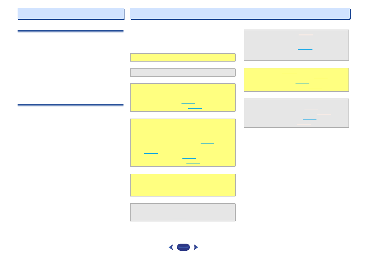
The unit is a full-fledged AV receiver equipped with an
abundance of functions and terminals. It can be used easily
after following the procedure below to make the connections
and settings.
The colors of the steps indicate the following:
Required setting item
Setting to be made as necessary
- - - - - - - - - - - - - - - - - - - - - - - - - - - - - - - - - - - - - - - - - -
Connecting the speakers
1
Where you place the speakers will have a big effect on
the sound.
•
Placing the speakers (page 11)
•
Connecting the speakers (page 12)
Connecting the components
2
For surround sound, you’ll want to hook up using a
digital connection from the Blu-ray Disc/DVD player to
the receiver.
•
About video outputs connection (page 14)
•
Connecting a TV and playback components
(page 15
)
•
Connecting antennas (page 17)
•
Plugging in the receiver (page 18)
Power On
3
Make sure you’ve set the video input on your TV to this
receiver. Check the manual that came with the TV if you
don’t know how to do this.
Specify the size and number of speakers you’ve
4
connected
•
Speaker Setting (page 29)
The Input Assign menu (page 31)
5
(When using connections other than the recommended
connections.)
The HDMI Setup menu (page 32
(When the connected TV supports the HDMI Audio
Return Channel function.)
Basic playback (page 19)
6
•
Selecting the audio input signal (page 19)
•
Playing a USB device (page 21)
•
Choosing the listening mode (page 25)
Adjusting the sound as desired
7
•
Using the Sound Retriever (page 26)
•
Better sound using Phase Control (page 26)
•
Setting the Audio options (page 27)
•
Manual speaker setup (page 29)
)
6
Chapter
Controls and displays
1
1
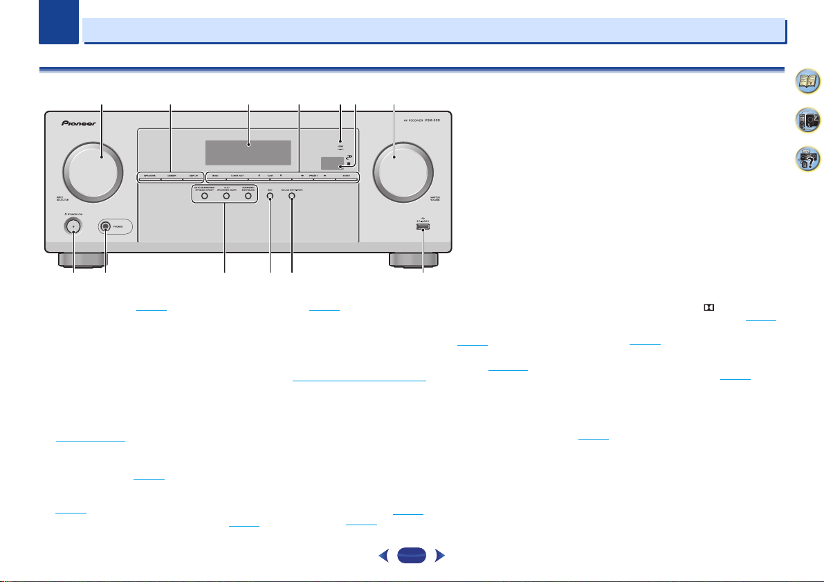
Front panel
3415 726
8 9 1110 12 13
1
INPUT SELECTOR
Selects an input source (page 19).
2
Receiver control buttons
SPEAKERS
When the SP OFF is selected, no sound is output from the
speakers connected to this receiver.
DIMMER
can be controlled in four steps.
DISPLAY
mode, sound volume, input name can be checked by
selecting an input source.
3
Character display
See Display on page 8.
4
Tuner control buttons
BAND
– Switches between AM, FM ST (stereo) and FM
MONO radio bands (page 23
TUNER EDIT
ENTER
to memorize and name stations for recall
(page 23
TUNE
/
dial
– Use to change the speaker system on or off.
– Dims or brightens the display. The brightness
– Switches the display of this unit. The listening
– Use with
).
– Used to find radio frequencies (page 23).
).
TUNE
/, PRESET
/
and
PRESET
/
(page 24
).
5
HDMI indicator
Blinks when connecting an HDMI-equipped component;
lights when the component is connected (page 15
6
Remote sensor
Receives the signals from the remote control (see Operating
range of remote control on page 10).
7
MASTER VOLUME
8
STANDBY/ON
9
PHONES jack
Use to connect headphones. When the headphones are
connected, there is no sound output from the speakers. The
listening mode when the sound is heard from the headphone
can be selected only from PHONES SURR, STEREO or
STEREO ALC mode.
10
Listening mode buttons
AUTO SURROUND/STREAM DIRECT
Auto surround mode (page 25
playback (page 26
– Use to select preset radio stations
).
dial
– Switches between
).
) and Stream Direct
ALC/STANDARD SURR
and to switch between the modes of Pro Logic and
NEO:6, and the Auto level control stereo mode (page 25
ADVANCED SURROUND
surround modes (page 26
11
ECO
Switches between ECO Mode 1/ECO Mode 2. When ECO
Mode is turned ON, the display will go dark (page 26
12
SOUND RETRIEVER
Turn sound retriever effect on/off.
13
USB terminal
Use to connect your USB mass storage device as an audio
source (page 18
).
– Press for standard decoding
– Switches between the various
).
).
).
7
1
14 15 16 17 18 16
21 22 23 24 24 25
19
20
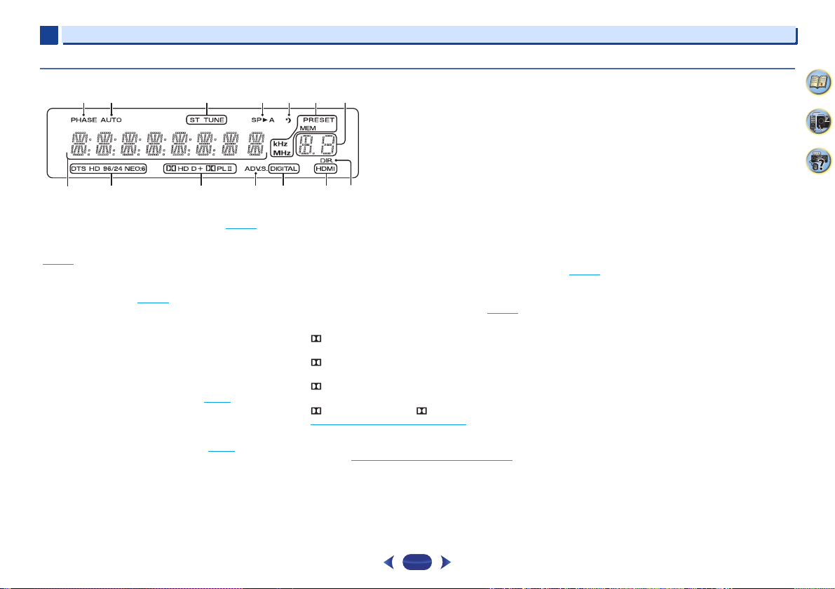
1
Display
Controls and displays
14
PHASE
Lights when the Phase Control is switched on (page 26).
15
AUTO
Lights when the Auto Surround feature is switched on
(page 25
).
16
Tuner indicators
ST – Lights when a stereo FM broadcast is being received
in auto stereo mode (page 23
TUNE – Lights when a normal broadcast channel.
PRESET – Shows when a preset radio station is registered
or called.
MEM – Blinks when a radio station is registered.
kHz/MHz – Lights when the character display is showing
the currently received AM/FM broadcast frequency.
17
Speaker indicators
Shows if the speaker system is on or not (page 7).
SPA means the speakers are switched on.
SP means the speakers are switched off.
18
Sleep timer indicator
Lights when the receiver is in sleep mode (page 9).
19
PRESET information or input signal indicator
Shows the preset number of the tuner or the input signal type,
etc.
20
Character display
Displays various system information.
).
21
DTS indicators
DTS – Lights when a source with DTS encoded audio
signals is detected.
HD – Lights when a source with DTS-EXPRESS or DTS-HD
encoded audio signals is detected.
96/24 – Lights when a source with DTS 96/24 encoded
audio signals is detected.
NEO:6 – When one of the NEO:6 modes of the receiver is
on, this lights to indicate NEO:6 processing (page 25
22
Dolby Digital indicators
D – Lights when a Dolby Digital encoded signal is
detected.
D+ – Lights when a source with Dolby Digital Plus
encoded audio signals is detected.
HD – L igh ts whe n a sou rce wi th D olb y T rue HD e nc ode d
audio signals is detected.
PLII – Lights to indicate Pro Logic II decoding (see
Listening in surround sound
23
ADV.S.
Lights when one of the Advanced Surround modes has been
selected (see Using the Advanced surround
more on this).
24
SIGNAL SELECT indicators
DIGITAL – Lights when a digital audio signal is selected.
Blinks when a digital audio signal is selected and selected
audio input is not provided.
on page 25 for more on this).
on page 26 for
8
HDMI – Lights when an HDMI signal is selected. Blinks
when an HDMI signal is selected and selected HDMI input
is not provided.
25
DIR.
Lights when the DIRECT or PURE DIRECT mode is switched
on (page 26
).
).
1
2
13
14
15
16
17
3
4
7
6
5
8
9
10
11
12
RECEIVER
RECEIVER
1
1
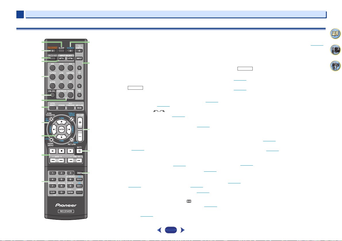
Remote control
As for operating other devices, the remote control codes for
the Pioneer products are preset. The settings cannot be
changed.
1
SLEEP
Press to change the amount of time before the receiver
switches into standby (30 min – 60 min – 90 min – Off). You
can check the remaining sleep time at any time by pressing
SLEEP
once.
2
RECEIVER
Switches the receiver between standby and on.
3
Switches the remote to control the receiver (used to select the
white commands above the number buttons (
etc)). Also use this button to set up surround sound (page 29
or Audio parameters (page 27
4
INPUT SELECT
Use to select the input source (page 19).
5
Input function buttons
Use to select the input source to this receiver (page 19). This
will enable you to control other Pioneer components with the
remote control.
6
SIG SEL
Press to select the audio input signal of the component to play
back (page 19
7
Sound control buttons
S.RETRIEVER
compressed audio sources (page 26
PHASE
8
Listening mode and component control buttons
AUTO/DIRECT
(page 25
STEREO
ALC/STANDARD SURR
and to switch between the modes of Pro Logic II and
NEO 6, and the Auto level control stereo mode (page 25
ADV SURR
modes (page 26
).
– Press to restore CD quality sound to
– Press to switch on/off Phase Control (page 26).
– Switches between Auto surround mode
) and Stream Direct playback (page 26).
– Press to select stereo playback (page 25).
– Switches between the various surround
).
– Press for standard decoding
).
).
MIDNIGHT
,
Controls and displays
ECO
– Switches between ECO Mode 1/ECO Mode 2. When
ECO Mode is turned ON, the display will go dark (page 26
9
Receiver and component control buttons
The following button controls can be accessed after you have
selected the corresponding input function button (
etc.).
Press first to access:
AUDIO PARAMETER
(page 27
).
HOME MENU
(page 29
).
RETURN
– Confirm and exit the current menu screen.
BD
or
Press
)
Press
10
Use the arrow buttons when setting up your surround sound
system (page 29
menus/options.
Use
PRESET
(page 24
).
DVD
TOP MENU
Disc/DVD.
HOME MENU
RETURN
– Confirm and exit the current menu screen.
MENU
– Display s the TOOLS menu of Blu-ray Disc player.
TUNER
first to access:
TOOLS
– Memorizes stations for recall, also used to
change the name (page 24
BAND
– Switches between AM, FM ST (stereo) and FM
MONO radio bands (page 23
/// (TUNE
TUNE
/
/
can be used to select preset radio stations
).
– Use to access the Audio options
– Press to access the Home Menu
first to access:
– Displays the disc ‘top’ menu of a Blu-ray
– Displays the HOME MENU screen.
).
).
/, PRESET
). Also used to control Blu-ray Disc/DVD
can be used to find radio frequencies and
/
),
ENTER
BD, DVD
).
,
9
1
WARNING
CAUTION
RECEIVER
RECEIVER
30°
7 m (23 ft.)
30°
1
11
Component control buttons
The main buttons (, , etc.) are used to control a component
after you have selected it using the input function buttons.
The controls above these buttons can be accessed after you
have selected the corresponding input function button (
DVD
and CD). These buttons also function as described
below.
Press first to access:
BASS +/–, TRE +/–
• These controls are disabled when the listening mode is
set to DIRECT or PURE DIRECT.
• When the front speaker is set at SMALL in the Speaker
Setting and the X.Over is set above 150 Hz, the
subwoofer channel level will be adjusted by pressing
BASS +/–
12
Number buttons and other component controls
Use the number buttons to directly select a radio frequency
(page 23
) or the tracks on a CD, etc. There are other buttons
that can be accessed after is pressed. (For example
MIDNIGHT
CH SELECT
use
LEV +/–
LEV +/–
MIDNIGHT
(page 27
SPEAKERS
When the SP OFF is selected, no sound is output from the
speakers connected to this receiver.
DIMMER
can be controlled in four steps.
During ECO mode, the brightness switches between 2
levels. If the dimmest level is selected, DIMMER will be
shown on the display. (Mode other than ECO: 4 levels, ECO
mode: 2 levels)
13
SOURCE
Turns on or off the power of the Pioneer DVD/DVR units when
BD, DVD
or CD is selected using the input function buttons.
– Use to adjust Bass or Treble.
(page 30).
, etc.)
– Press repeatedly to select a channel, then
to adjust the level (page 30).
– Use to adjust the channel level.
– Switches to Midnight or Loudness listening
).
– Use to change the speaker system on or off.
– Dims or brightens the display. The brightness
14
TV CONTROL buttons
These buttons can control only be used with Pioneer TVs.
– Use to turn on/off the power of the TV.
INPUT
BD
,
– Use to select the TV input signal.
CH +/–
– Use to select channels.
VOL +/–
– Use to adjust the volume on your TV.
15
VOLUME +/–
Use to set the listening volume.
16
MUTE
Mutes/unmutes the sound.
17
DISP
Switches the display of this unit. The listening mode, sound
volume or input name can be checked by selecting an input
source.
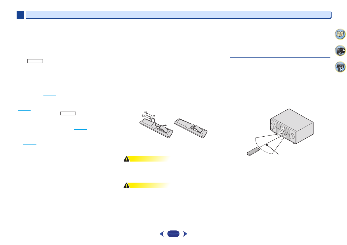
Loading the batteries
The batteries included with the unit are to check initial
operations; they may not last over a long period. We
recommend using alkaline batteries that have a longer life.
•
Do not use or store batteries in direct sunlight or other
excessively hot place, such as inside a car or near a heater.
This can cause batteries to leak, overheat, explode or catch
fire. It can also reduce the life or performance of batteries.
•
Incorrect use of batteries may result in such hazards as
leakage and bursting. Observe the following precautions:
-
Never use new and old batteries together.
-
Insert the plus and minus sides of the batteries properly
according to the marks in the battery case.
-
Batteries with the same shape may have different
voltages. Do not use different batteries together.
10
Controls and displays
-
When disposing of used batteries, please comply with
governmental regulations or environmental public
institution’s rules that apply in your country/area.
-
When inserting the batteries, make sure not to damage
the springs on the battery’s (–) terminals. This can cause
batteries to leak or overheat.
Operating range of remote control
The remote control may not work properly if:
•
There are obstacles between the remote control and the
receiver’s remote sensor.
•
Direct sunlight or fluorescent light is shining onto the
remote sensor.
•
The receiver is located near a device that is emitting
infrared rays.
•
The receiver is operated simultaneously with another
infrared remote control unit.
Chapter
CAUTION
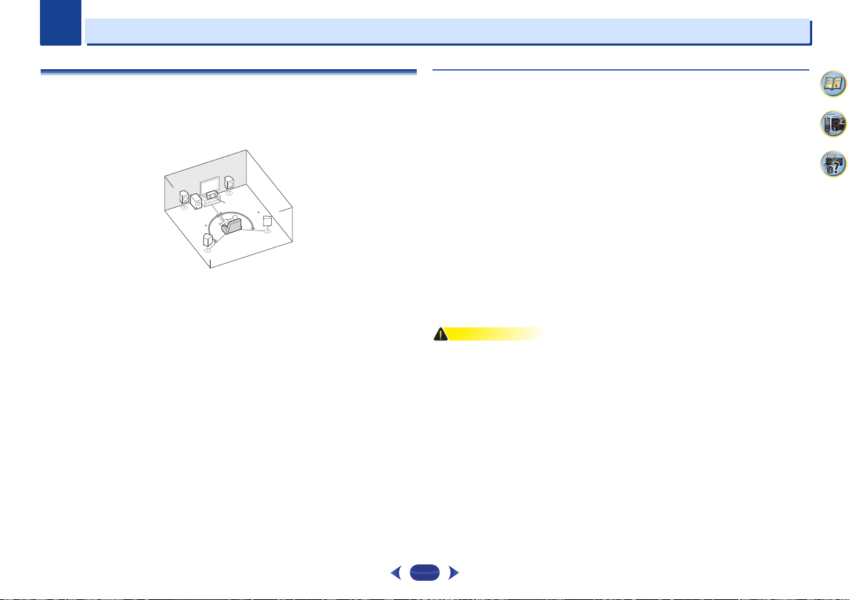
5.1 channel surround system:
2
2
Connecting your equipment
Placing the speakers
By connecting the left and right front speakers (L/R), the center speaker (C), the left and right
surround speakers (SL/SR), and the subwoofer (SW), a 5.1 ch surround system can be enjoyed.
To achieve the best possible surround sound, install your speakers as shown below.
L
R
C
SW
120
120
SR
SL
Hints on the speaker placement
Where you put your speakers in the room has a big effect on the quality of the sound. The
following guidelines should help you to get the best sound from your system.
•
The subwoofer can be placed on the floor. Ideally, the other speakers should be at about earlevel when you’re listening to them. Putting the speakers on the floor (except the subwoofer),
or mounting them very high on a wall is not recommended.
•
For the best stereo effect, place the front speakers 2 m to 3 m (6 ft. to 9 ft.) apart, at equal
distance from the TV.
•
If you’re going to place speakers around your CRT TV, use shielded speakers or place the
speakers at a sufficient distance from your CRT TV.
•
If you’re using a center speaker, place the front speakers at a wider angle. If not, place them
at a narrower angle.
•
Place the center speaker above or below the TV so that the sound of the center channel is
localized at the TV screen. Also, make sure the center speaker does not cross the line formed
by the leading edge of the front left and right speakers.
•
It is best to angle the speakers towards the listening position. The angle depends on the size
of the room. Use less of an angle for bigger rooms.
•
Surround speakers should be positioned 60 cm to 90 cm (2 ft. to 3 ft.) higher than your ears
and titled slight downward. Make sure the speakers don’t face each other. For DVD-Audio,
the speakers should be more directly behind the listener than for home theater playback.
•
Try not to place the surround speakers farther away from the listening position than the front
and center speakers. Doing so can weaken the surround sound effect.
•
Make sure that all speakers are securely installed. This not only improves sound quality, but
also reduces the risk of damage or injury resulting from speakers being knocked over or
falling in the event of external shocks such as earthquakes.
11
2
CAUTION
10 mm
(3/8 in.)
12 3
10 mm
(3/8 in.)
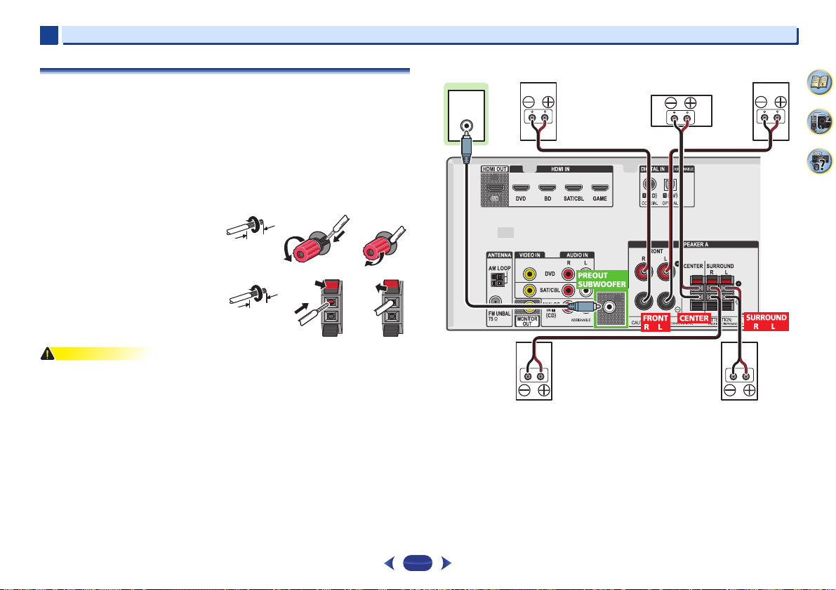
Center
Surround right
Front right
Front leftSubwoofer
Surround left
2
Connecting the speakers
The receiver will work with just two stereo speakers (the front speakers in the diagram) but
using at least three speakers is recommended, and a complete setup is best for surround
sound.
Make sure you connect the speaker on the right to the right (R) terminal and the speaker on the
left to the left (L) terminal. Also make sure the positive and negative (+/–) terminals on the
receiver match those on the speakers.
You can use speakers with a nominal impedance between 6 and 16 .
Be sure to complete all connections before connecting this unit to the AC power source.
Bare wire connections
Front speaker terminals:
1
Twist exposed wire strands together.
2
Loosen terminal and insert exposed wire.
3
Tighten terminal.
Center and surround speaker terminals:
1
Twist exposed wire strands together.
2
Push open the tabs and insert exposed
wire.
3
Release the tabs.
•
These speaker terminals carry HAZARDOUS LIVE voltage. To prevent the risk of electric
shock when connecting or disconnecting the speaker cables, disconnect the power cord
before touching any uninsulated parts.
•
Make sure that all the bare speaker wire is twisted together and inserted fully into the
speaker terminal. If any of the bare speaker wire touches the back panel it may cause the
power to cut off as a safety measure.
12 3
LINE LEVEL
INPUT
Connecting your equipment
12
 Loading...