

Page 1

AUDIO/VIDEO
MULTI-CHANNEL RECEIVER
VSX-409RDS
Operating Instructions
Page 2
Congratulations on buying this fine Pioneer
product.
Please read through these operating instructions
so you will know how to operate your model
properly. After you have finished reading the
instructions, put them away in a safe place for
future reference.
In some countries or regions, the shape of the
power plug and power outlet may sometimes
differ from that shown in the explanatory
drawings. However the method of connecting
and operating the unit is the same.
THE POWER SWITCH IS SECONDARY
CONNECTED AND THEREFORE DOES NOT
SEPARATE THE UNIT FROM MAINS
POWER IN STANDBY POSITION.
IMPORTANT
CAUTION
RISK OF ELECTRIC SHOCK
DO NOT OPEN
The lightning flash with arrowhead symbol,
within an equilateral triangle, is intended to
alert the user to the presence of uninsulated
"dangerous voltage" within the product's
enclosure that may be of sufficient magnitude
to constitute a risk of electric shock to persons.
CAUTION:
TO PREVENT THE RISK OF ELECTRIC SHOCK,
DO NOT REMOVE COVER (OR BACK). NO
USER-SERVICEABLE PARTS INSIDE. REFER
SERVICING TO QUALIFIED SERVICE
PERSONNEL.
WARNING: TO PREVENT FIRE OR SHOCK HAZ-
ARD, DO NOT EXPOSE THIS APPLIANCE TO RAIN OR
MOISTURE.
VENTILATION
¶ When installing this unit, make sure to leave space
around the unit for ventilation to improve heat
radiation (at least 20 cm at top, 15 cm at rear, and
15 cm at each side). If not enough space is provided
between the unit and walls or other equipment, heat
will build up inside, interfering with performance
or causing malfunctions.
¶ Do not place on a thick carpet, bed, sofa, or fabric
having a thck pile. Do not cover with fabric or
covering.
Anything that blocks ventilation will cause intenal
tempture to rise, which may lead to breakdown or
fire hazard.
This product complies with the Low Voltage Directive
(73/23/EEC), EMC Directives (89/336/EEC, 92/31/EEC)
and CE Marking Directive (93/68/EEC).
The exclamation point within an equilateral
triangle is intended to alert the user to the
presence of important operating and
maintenance (servicing) instructions in the
literature accompanying the appliance.
Do not connect either wire to the earth terminal
of a three-pin plug.
NOTE
After replacing or changing a fuse, the fuse cover
in the plug must be replaced with a fuse cover
which corresponds to the colour of the insert in
the base of the plug or the word that is embossed
on the base of the plug, and the appliance must
not be used without a fuse cover. If lost,
replacement fuse covers can be obtained from
your dealer.
Only 5 A fuses approved by B.S.I. or A.S.T.A. to
B.S. 1362 should be used.
IMPORTANT
FOR USE IN THE UNITED
KINGDOM
The wires in this mains lead are coloured in
accordance with the following code:
If the plug provided is unsuitable for your socket
outlets, the plug must be cut off and a suitable
plug fitted.
Blue : neutral
Brown : live
The cut-off plug should be disposed of and must
not be inserted into any 13 amp socket as this can
result in electric shock. The plug or adaptor of the
distribution panel should be provided with a 5 amp
fuse. As the colours of the wires in the mains lead
of this appliance may not correspond with coloured
markings identifying the terminals in your plug,
proceed as follows:
The wire which is coloured blue must be
connected to the terminal which is marked with
the letter N or coloured black.
The wire which is coloured brown must be
connected to the terminal which is marked with
the letter L or coloured red.
Information to User
Alteration or modifications carried out without appropriate authorization may invalidate the user's right to
operate the equipment.
2
Page 3

Table of Contents
Introductory Information ..................................... 5
Checking the Supplied Accessories ............................................................... 5
Using this Manual........................................................................................... 5
Preparing the Remote Control........................................................................ 6
Connecting Your System ..................................... 7
Connecting Antennas ..................................................................................... 7
Connecting Audio Components ..................................................................... 8
Connecting DVD 5.1 Channel Components ................................................... 9
Connecting Video Components.................................................................... 10
Connecting Speakers ................................................................................... 11
Setting Up for Surround Sound........................ 13
Setting Up for Surround Sound .................................................................... 13
Displays & Controls............................................ 17
Front Panel ................................................................................................... 17
Display.......................................................................................................... 18
Remote Control ............................................................................................ 19
Listening in Surround Sound ............................ 20
Listening in Dolby Pro Logic Mode .............................................................. 20
Listening in DVD 5.1 Channel Input Mode ................................................... 21
Listening in DSP Mode................................................................................. 22
Set up Operation
Using the Tuner .................................................. 23
Finding a Station........................................................................................... 23
Tuning Directly to a Station........................................................................... 24
Memorizing Stations .................................................................................... 25
Naming Memorized Stations........................................................................ 26
Recalling Memorized Stations...................................................................... 27
An Introduction to RDS & EON .................................................................... 28
Searching for RDS Programmes .................................................................. 30
Using EON Search........................................................................................ 31
Making a Recording ........................................... 32
Making an Audio Recording ......................................................................... 32
Making a Video Recording............................................................................ 33
Controlling the Rest of Your System ................ 34
CD/MD/CD-R Player Controls....................................................................... 34
Cassette Deck Controls................................................................................ 35
DVD Player Controls..................................................................................... 36
TV Controls................................................................................................... 37
Additional Information....................................... 38
Troubleshooting ............................................................................................ 38
Specifications ............................................................................................... 40
3
Page 4

Features
Five channels of independent amplification
Five independent power amplifiers, each rated at 80W, ensure accurate, dynamic reproduction
of all multi-channel material.
Dolby* Pro Logic
Enjoy stunning multi-channel, surround sound effects from movies and other material recorded
in Dolby Surround/Pro Logic. Enhance your listening experience further with built-in signal
processing that recreates the movie theater ambience in your living room.
Digital surround effects
Using Digital Signal Processing (DSP) technology, various listening environments, such as a
theater or a jazz club, may be simulated and applied to any music or video source.
Convenient RDS/EON radio tuning
Use the fast and convenient RDS system to immediately find the type of radio programme
you want to listen to. This program identification system could also be extremely useful in
locating helpful broadcasts in emergencies or adverse weather conditions.
DVD 5.1 channel input
A special 5.1 Channel input makes the VSX–409RDS fully compatible with Dolby Digital
decoders and DVD players with 5.1 channel outputs.
The Energy-saving Design
This unit is designed to use minimal electricity when power is switched OFF (in Standby
mode). Regarding the value of the power consumption in standby mode, refer to
“Specifications” on pages 40.
* Manufactured under license from Dolby Laboratories.
"Dolby", "Pro Logic" and double-D symbol are trademarks
of Dolby Laboratories. Confidential unpublished works. ©
1992-1997 Dolby Laboratries.All rights reserved.
4
Page 5
Introductory Information
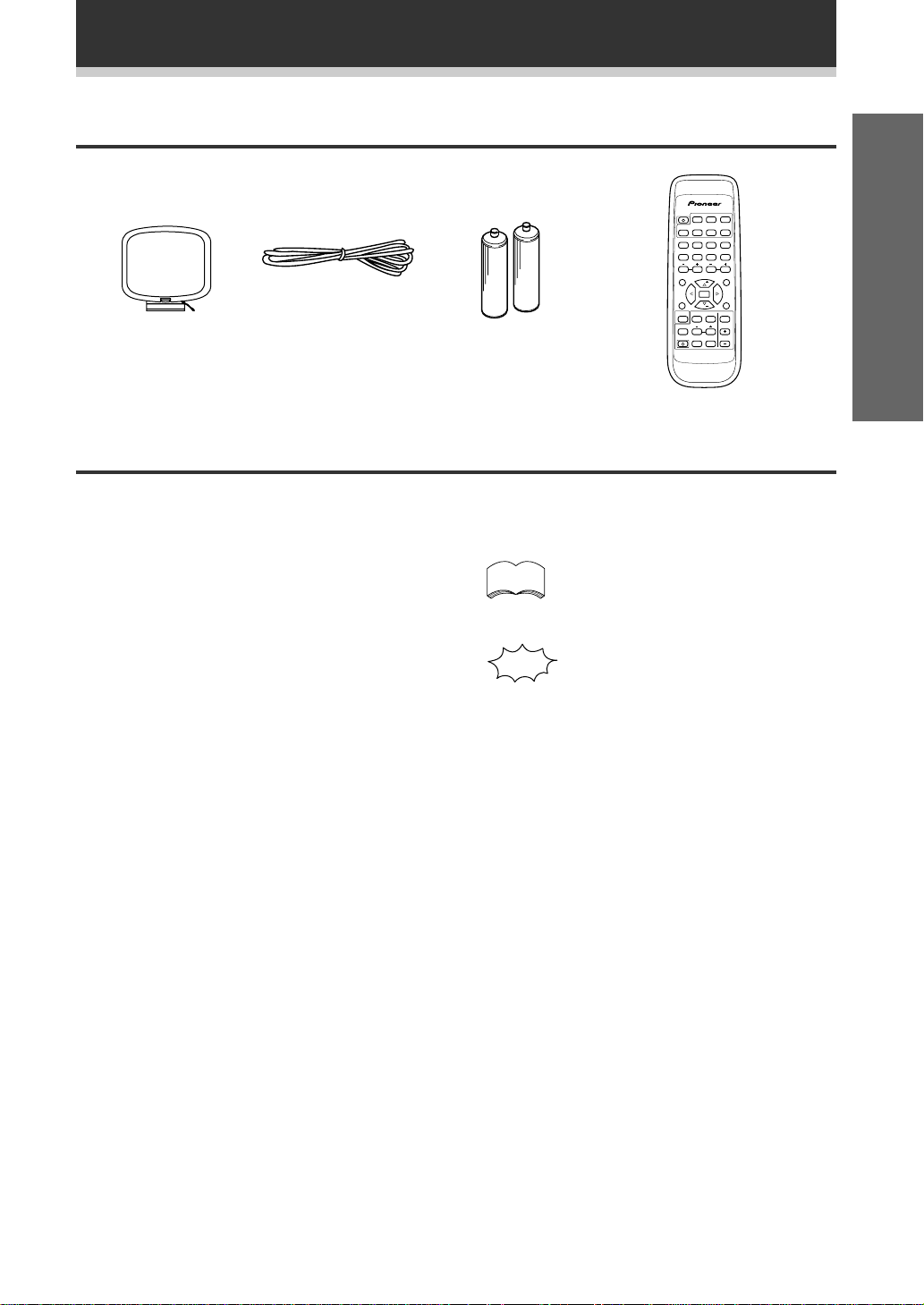
Checking the Supplied Accessories
Please check that you've received the following supplied accessories:
AM loop antenna FM wire antenna
Using this Manual
'AA' size IEC R6P
batteries (x2)
SOURCE SELECT
SOURCE
TUNER
DVD
CD
TV CONT.
MD
CD-R
TAPE
!
!
$
$
1234
*&#
569078
TV VOL.
CHANNEL
EFFECT
STATION
CLASS
D. ACCESS
MENU
TOP MENU
FQ
RF ATT
DISP
ENTER
TEST
MPX
TONE
SET UP
FQ
MUTING
DSP MODESORROUND
2
CH. SELECT
LEVEL
MASTER
FL
FUNCTION
RECEIVER
VOLUME
DIMMER
AV MULTI-CHANNEL RECEIVER
REMOTE CONTROL UNIT
Î
Remote control unit
Set up
This manual is for the VSX-409RDS audio/video
multi-channel receiver. It is divided into two main
sections:
Set up
This section covers installing your receiver and
connecting up all the other components in your
home theater system to it. It also describes how to
set up a multi-channel speaker system to take full
advantage of the great surround sound features of
your receiver.
Operation
This section shows you how to use every feature of
the receiver and its remote control unit. It also
covers using the supplied remote control to operate
your other Pioneer home theater components. To
find out more about a specific button, control or
indicator, see Displays & Controls starting on page
17. This will point you to the relevant chapter in the
manual.
In the Additional Information section (p.38-40) you'll
find a troubleshooting section and specifications.
memo
The following symbols are used
throughout this manual:
Provides detailed precautions and
advice on operations, etc.
Indicates that display is blinking.
5
Page 6
Introductory Information
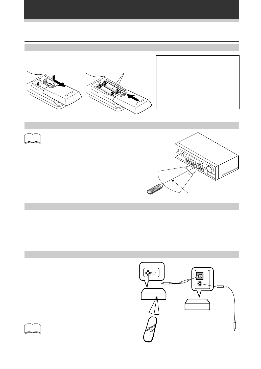
Preparing the Remote Control
Loading the batteries
Dry cell batteries
('AA' size IEC R6P ¥ 2)
Operating range of remote control unit
memo
The remote control may not work properly if:
¶ There are obstacles between the remote control
and the receiver's remote sensor.
¶ Direct sunlight or fluorescent light is shining onto
the remote sensor.
¶ The receiver is located near a device that is
emitting infrared rays.
¶ The receiver is operated simultaneously with
another infrared remote control unit.
Special note on the remote control
CAUTION!
Incorrect use of batteries may result in such
hazards as leakage and bursting. Observe
the following precautions:
¶ Never use new and old batteries together.
¶ Insert the plus and minus sides of the
batteries properly according to the marks
in the battery case.
¶ Batteries with the same shape may have
different voltages. Do not use different
batteries together.
30
30
1 2 3
4 5 6
+
+
-
7m
Please note that the remote control has two types of buttons, one called FUNCTION and a set of buttons called
SOURCE SELECT. Use the FUNCTION button to choose the component you want to listen to (CD, CDR/TAPE,
TUNER, etc.) and use the SOURCE SELECT buttons to change which component the remote control itself will
operate. Thus, if the VSX-409RDS is in TUNER mode, for example, and you want to listen to your CD player, you
need to select the CD mode with the FUNCTION button.
Operating other Pioneer components
By connecting a control cord (optional), you can
control other Pioneer equipment using this remote
control unit. Point the remote control unit towards
the remote sensor of this unit, even when operating
other equipment.
The remote control signals are received by the
remote sensor of this unit, and sent to the other
devices via the CONTROL OUT terminal.
memo
You can also control Pioneer components
by pointing the receiver's remote control
directly at the component. This type of
operation does not require control cords.
VSX-409RDS
Remote control unit
CONTROL
OUT
CONTROL
IN
OUT
Other Pioneer products
with Î mark
Connect to CONTROL IN
terminal of other Pioneer
products with Î mark.
6
Page 7
Connecting Your System
Before making or changing the connections, switch off the power switch and disconnect the power
cord from the AC outlet.
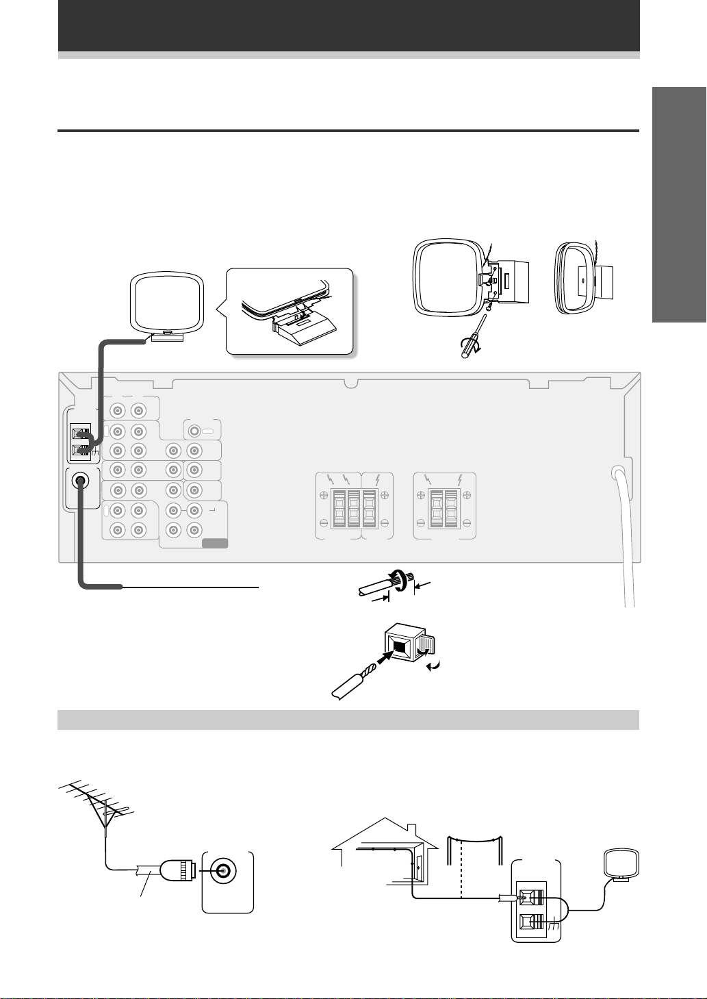
Connecting Antennas
Connect the AM loop antenna and the FM wire antenna as shown below. To improve reception and sound
quality, connect external antennas (see Using external antennas, below). Always make sure that the receiver is
switched off and unplugged from the wall outlet before making or changing any connections.
AM loop antenna
Assemble the antenna and connect to the receiver. Attach to
a wall, etc. (if desired) and face in the direction that gives the
best reception.
L
R
AM LOOP
ANTENNA
FM ANTENNA
FM
UNBAL
75Ω
IN
O
U
T
IN
IN
IN
R
E
C
P
L
A
Y
VCR/
DVR
TV/
SAT
CD-R
/TAPE
/MD
IN
CD
DVD
/LD
FRONT
OUT
IN
IN
IN
SUB
WOOFER
CONTROL
OUT
OUT
TO
MONITOR
TV
SUB
WOOFER
PREOUT
SURROUND
LR
CENTER
DVD 5.1 CH
INPUT
LRLR
FRONT
SPEAKERS
CENTER
SPEAKER
SURROUND
SPEAKERS
Set up
FM wire antenna
Connect the FM wire antenna and fully extend
vertically along a window frame, etc.
Using external antennas
7 To improve FM reception
Connect an external FM antenna.
FM ANTENNA
FM
UNBAL
75 Ω coaxial cable
75Ω
7 To improve AM reception
Connect a 5–6 meter length of vinyl-coated wire to the AM antenna
terminal without disconnecting the supplied AM loop antenna.
For the best possible reception, suspend horizontally outdoors.
Indoor antenna
(Vinyl-coated wire)
10mm
Outdoor antenna
5–6m
Antenna snap connectors
Twist the exposed wire strands
together and insert into the hole,
then snap the connector shut.
AM LOOP
ANTENNA
7
Page 8
Connecting Your System
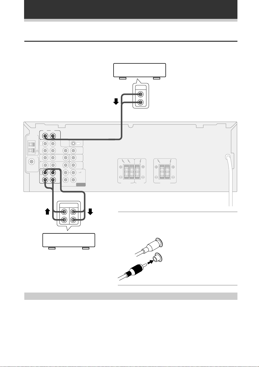
Connecting Audio Components
Connect your audio components as shown below. When connecting equipment, always make sure the power
switched off and the power cord is disconnected from the wall outlet.
CD player
OUT
L
R
L
R
AM LOOP
ANTENNA
FM ANTENNA
FM
UNBAL
75Ω
IN
O
U
T
IN
IN
IN
R
E
C
P
L
A
Y
VCR/
DVR
TV/
SAT
CD-R
/TAPE
/MD
IN
CD
DVD
/LD
FRONT
OUT
IN
IN
IN
SUB
WOOFER
CONTROL
OUT
TO
MONITOR
TV
SUB
WOOFER
PREOUT
SURROUND
LR
CENTER
DVD 5.1 CH
INPUT
LRLR
FRONT
SPEAKERS
CENTER
SPEAKER
SURROUND
SPEAKERS
PLAY REC
L
R
Audio cords
Use good quality audio cords with RCA/phono plugs at each
end (not supplied) to connect your audio components.
CD-R , Cassette deck
MD , DA T etc.
L
Connect red plugs to R (right) and
white plugs to L (left) terminals.
R
Be sure to push home the plugs into
their sockets.
Cassette deck placement
Depending on where the cassette deck is placed, noise caused by leakage flux from the transformer in the
receiver may occur during playback. If you experience noise, move the cassette deck farther away from the
receiver.
8
Page 9
Connecting Your System
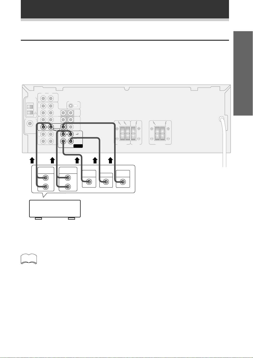
Connecting DVD 5.1 Channel Components
DVD and LD discs are often compatible with both 2 channel and 5.1 channel audio output formats. Refer to page
21 for more information on how to switch between the two input methods.
Connections can be made from a DVD player, multi channel decoder equipped with 5.1 analogue outputs to the
5.1 analogue inputs on this unit. When connecting equipment, always make sure the power switched off and
the power cord is disconnected from the wall outlet.When connecting equipment, always make sure the power
switched off and the power cord is disconnected from the wall outlet.
L
R
AM LOOP
ANTENNA
FM ANTENNA
FM
UNBAL
75Ω
IN
O
U
T
IN
IN
IN
R
E
C
P
L
A
Y
VCR/
/TAPE
DVR
TV/
SAT
CD
DVD
/LD
OUT
CD-R
/MD
IN
FRONT
IN
IN
IN
SUB
WOOFER
CONTROL
OUT
TO
MONITOR
TV
SUB
WOOFER
PREOUT
SURROUND
LR
CENTER
DVD 5.1 CH
INPUT
LRLR
FRONT
SPEAKERS
CENTER
SPEAKER
SURROUND
SPEAKERS
Set up Operation
L
R
SURROUND
OUT PUT
L
R
SUB
WOOFER
CENTER
VODEO
OUT
FRONT
OUT PUT
Components equipped
with 5.1 channel
analogue output jacks
memo
The 5.1 channel input can only be used when DVD 5.1 CH is selected.
9
Page 10
VIDEO
IN
Connecting Your System
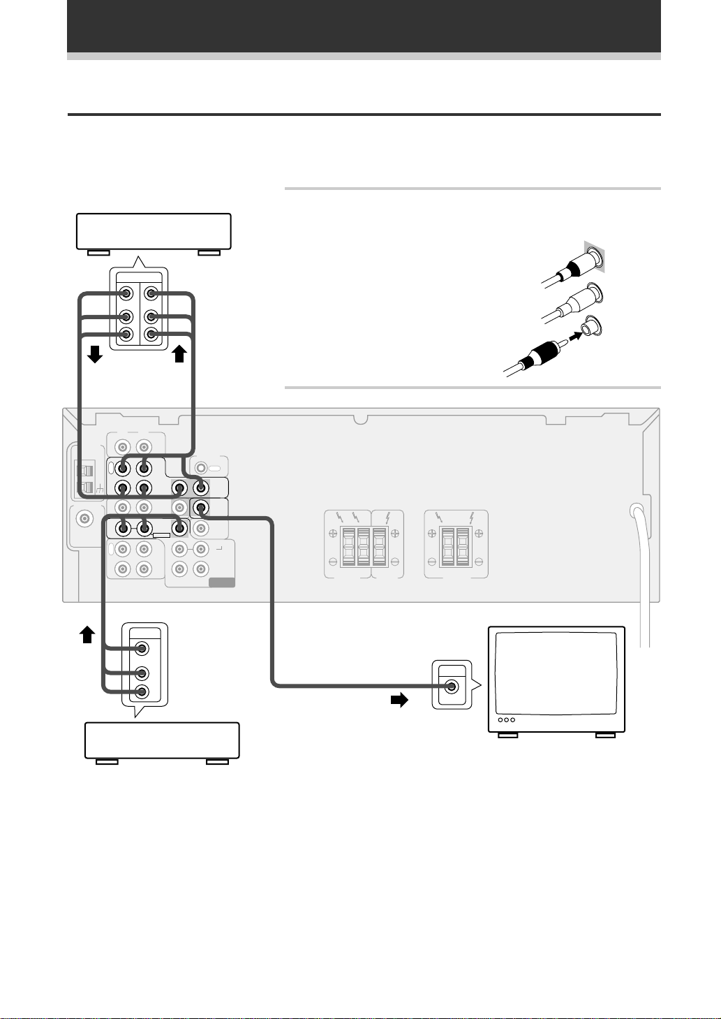
Connecting Video Components
Connect your video components as shown below. When connecting equipment, make sure the power is
switched off and the power cord disconnected from the wall outlet.
Audio/Video cords
Use good quality audio/video cords with RCA/phono plugs at each end
VCR, DVR, etc.
(not supplied) to connect the video components and a video cord to
connect the monitor/TV.
AM LOOP
ANTENNA
FM ANTENNA
FM
UNBAL
75Ω
IN
O
U
T
IN
IN
IN
R
E
C
P
L
A
Y
OUT IN
V
L
R
R
OUT
Connect red plugs to R (right), white plugs to
L (left), and the yellow plugs to VIDEO.
Be sure to push home the plugs into their
sockets.
L
VCR/
/TAPE
CD
DVR
TV/
SAT
DVD
/LD
FRONT
OUT
CD-R
/MD
IN
V
L
R
IN
IN
IN
SUB
WOOFER
CONTROL
OUT
OUT
TO
MONITOR
TV
SURROUND
LR
CENTER
DVD 5.1 CH
INPUT
LRLR
CENTER
FRONT
SPEAKER
SPEAKERS
SURROUND
SPEAKERS
IN
VIDEO
TV
monitor
10
DVD , LD player
Page 11
ª
·
Connecting Your System
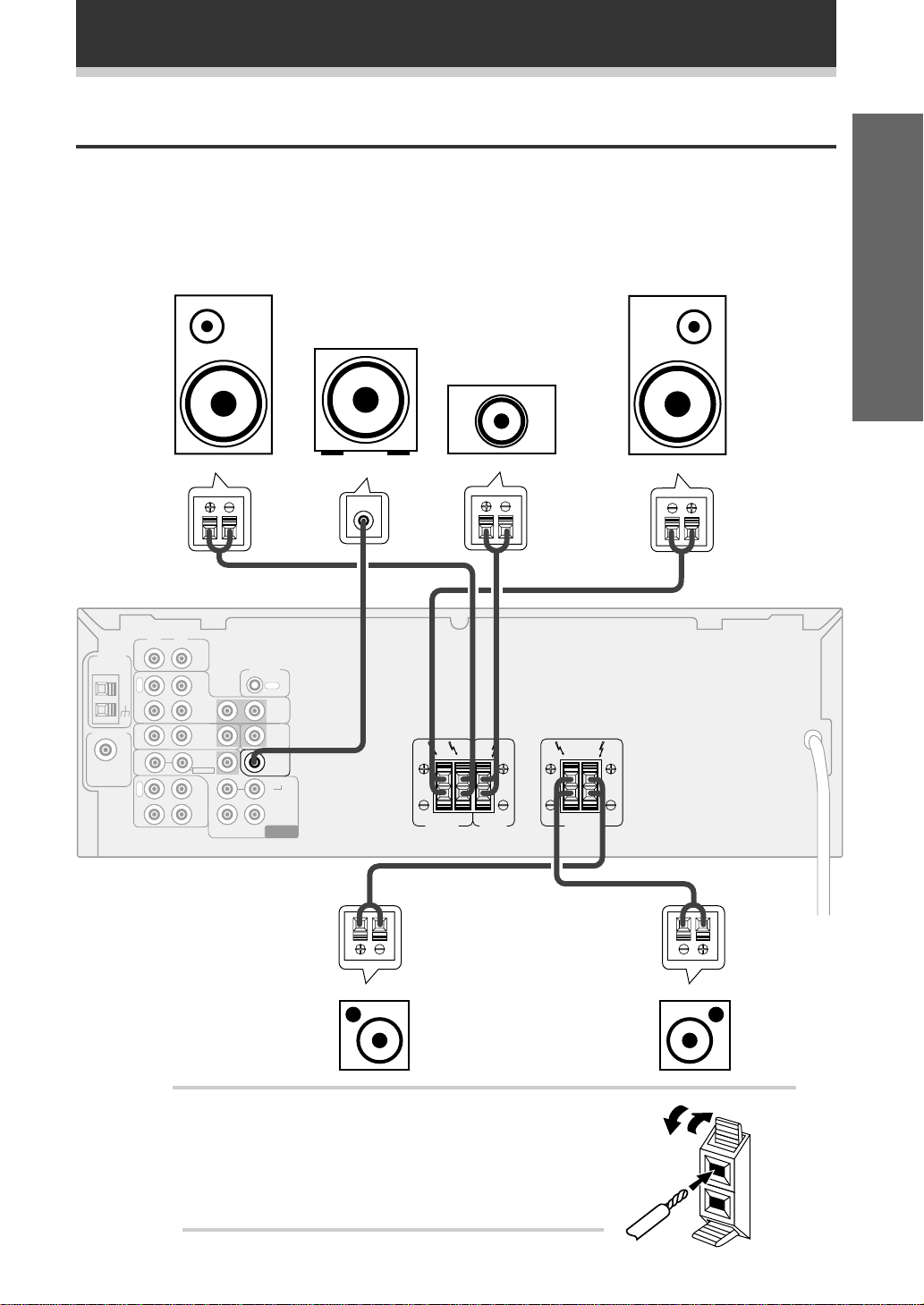
Connecting Speakers
Connect your speakers as shown below. Be sure to connect each speaker to the appropriate speaker terminals,
and also to connect the positive and negative terminals correctly (positive to positive, negative to negative).
When connecting equipment, always make sure the power switched off and the power cord is disconnected
from the wall outlet.
• Use speakers with a nominal impedance of 8 Ω to 16 Ω.
When connecting equipment, always make sure the power switched off and the power cord is disconnected
from the wall outlet.
Set up Operation
AM LOOP
ANTENNA
FM ANTENNA
FM
UNBAL
75Ω
Front
(left)
IN
O
U
T
IN
IN
IN
R
E
C
P
L
A
Y
Powered
sub-woofer
Front
(right)
Center
INPUT
L
R
VCR/
DVR
TV/
SAT
CD-R
/TAPE
/MD
CD
DVD
/LD
OUT
IN
FRONT
IN
IN
IN
SUB
WOOFER
CONTROL
OUT
OUT
TO
MONITOR
TV
SUB
WOOFER
PREOUT
SURROUND
LR
CENTER
DVD 5.1 CH
INPUT
LRLR
FRONT
SPEAKERS
CENTER
SPEAKER
SURROUND
SPEAKERS
Surround
(left)
Speaker terminals
Use good quality speaker wire to connect the speakers to the
receiver.
1 Twist around 10 mm of bare wire strands together.
2 Unclip the speaker terminal and insert the wire.
3 Snap shut the speaker terminal to secure.
Surround
(right)
11
Page 12
Connecting Your System
Hints on speaker placement
Speakers are usually designed with a particular placement in mind. Some are designed to be floorstanding, while
others should be placed on stands to sound their best. Some should be placed near a wall; others should be
placed away from walls. Follow the guidelines on placement that the speaker manufacturer provided with your
particular speakers to get the most out of them.
• Place the front left and right speakers at equal
distances from the TV.
• When placing speakers near the TV, we
recommend using magnetically shielded speakers
to prevent possible interference, such as
discoloration of the picture when the TV is switched
on. If you do not have magnetically shielded
speakers and notice discoloration of the TV picture,
move the speakers farther away from the TV.
• Install the center speaker above or below the TV
so that the sound of the center channel is localized
at the TV screen.
CAUTION!
If you choose to install the center speaker on
top of the TV, be sure to secure it with putty,
or by other suitable means, to reduce the risk
of damage or injury resulting from the speaker
falling from the TV in the event of external
shocks such as earthquakes.
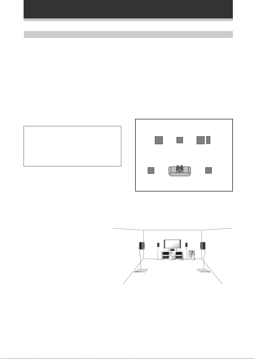
To achieve the best possible surround sound, install
your speakers as shown below. Be sure all speakers
are installed securely to prevent accidents and
improve sound quality.
Front
Left
Center
Front
Right
Sub
Woofer
Surround
Left
Surround
Right
• If possible, install the surround speakers slightly
above ear level.
• T ry not to install the surround speakers farther away
from the listening position than the front and center
speakers. Doing so can weaken the surround sound
effect.
Listening
Position
3-D View of speaker set up
12
Page 13

Setting Up for Surround Sound
Setting Up for Surround Sound
The VSX-409RDS offers several options for surround sound listening, depending on the speakers in your set up.
Having installed the speakers in your room it's important to set up the relative volume levels and speaker
distances in order to make the most of the receiver's surround sound capabilities. You only need to make these
settings once, unless you change the placement of your current speaker system or add new speakers, etc.
Setting the center mode, the subwoofer and speaker distances
It is important to set the type of center mode which corresponds to your speaker system, set the subwoofer on/
off and set speaker distances as well as set volume levels of each speaker. From your normal listening position,
the volumes of the various speakers in your system should appear to be equal. Follow the steps below to do all
of these things, especially adjust the volumes of the center and surround speakers relative to the main front
speakers for Dolby Pro Logic mode, 5.1 CH. mode and the DSP mode.
1
Switch on the receiver.
The STANDBY indicator goes out.
2
Press the SURROUND button.
Set up Operation
2
1
1
SOURCE SELECT
SOURCE
DVD
CD
TV CONT.
MD
TAPE
!
$
$
1234
TV FUNC.
*&#@
56
78
TV VOL.
CHANNEL
EFFECT
RF ATT
2
FUNCTION
STATION
FQ
DISP
ENTER
FQ
DSP MODESORROUND
LEVEL
FL
DIMMER
90
D. ACCESS
TOP MENU
TEST
TONE
CH. SELECT
RECEIVER
AV MULTI-CHANNEL RECEIVER
REMOTE CONTROL UNIT
MUTING
MASTER
VOLUME
TUNER
CD-R
CLASS
MENU
SET UP
3
Press the 3 button to select the surround
sound setup mode.
!
4
3
MPX
4
Î
Repeatedly pressing the button cycles through the three setup
modes (center mode setup; subwoofer setup; distance setup). The
mode appers in the display on the front panel.
4
Use the 5∞ buttons to select one of the four
types of center mode.
See the center mode cycle shown here and the diagrams below
explaining each center mode to decide which center mode to
choose
Normal
Middle and high frequency sounds are heard from
the center speaker.
Bass frequencies from the center channel are
played through the front speakers.
3 Stereo
Surround channel sounds and center channel bass
frequencies are heard through the front stereo
speakers.
Phantom
Center channel sounds are played through both
front speakers equally.
NORMAL
3
WIDE
3 STEREO
22
2
3
PHANTOM
33
2
Wide
If a full range speaker is used for the center
channel, all center channel sound, including bass
frequencies, are heard through the center
speaker.
13
Page 14

Setting Up for Surround Sound
5
6
SOURCE SELECT
SOURCE
TV CONT.
$
1234
TV FUNC.
56
TV VOL.
EFFECT
90
D. ACCESS
TOP MENU
RF ATT
TEST
TONE
CH. SELECT
FUNCTION
RECEIVER
AV MULTI-CHANNEL RECEIVER
REMOTE CONTROL UNIT
TUNER
DVD
CD
MD
CD-R
TAPE
!
!
$
2
*&#@
FQ
ENTER
FQ
LEVEL
78
CHANNEL
STATION
DISP
DSP MODESORROUND
FL
DIMMER
MUTING
MASTER
VOLUME
CLASS
MENU
SET UP
Î
6
, 8,10
MPX
5,7,9
6, 8,10
7
8
Press the 3 button to select the SUBWF
(subwoofer) select mode.
Use the 5∞ buttons to turn the subwoofer
function on or off.
Select SUBWF ON if you have a subwoofer and SUBWF OFF if
you don't have a subwoofer.
Press the 3 button to select the distance
mode for the FRNT (front) speakers.
For true surround sound effect the sound from the front speakers
and the surround speakers should arrive to the listener's ears at a
slightly different time. Telling the receiver how far your front and
surround speakers are from your listening position will allow the
receiver to do this correctly for you. The first distance setting you'll
see will be FRNT for your front speakers. You can set the distance
in a range from 0.3-9 metres.
Press the 5∞ buttons to increase/decrease
the distance of the FRNT speakers.
You need to judge how far the speakers are from your normal
listening position and set the distance accordingly. You can set the
distance in a range from 0.3–9 metres.
9
Press the 3 button to select the distance
mode for the SURR (surround) speakers.
10
Press the 5∞ buttons to increase/decrease
the distance of the SURR speakers.
Again, You need to judge how far the speakers are from your
normal listening position and set the distance accordingly. As
above, you can set the distance in a range from 0.3-9 metres.
When you are finished setting up the distance the receiver will
return to normal operating mode after about 20 seconds.
Alternatively, you can cycle through the setup mode options with
the 2, 3 buttons until you return to the regular operating mode.
memo
You only need to do the distance settings if your system has
surround speakers.
14
Page 15

Setting Up for Surround Sound
Setting up speaker levels for Dolby Pro Logic
In order to get the best surround sound you need to set up the relative speaker levels so that they all have the
same volume from your normal listening position. Follow the steps below using the TEST TONE to do this.
1
Press the SURROUND button.
2
Press the 2 button.
3
Press the TEST TONE button.
A short test tone will be heard from each speaker in your set up in
turn. No test tone is heard from the sub woofer, however.
4
Adjust the respective speaker levels with the
LEVEL +/– buttons when the TEST TONE
sounds from that speaker.
Adjust the volumes of the speakers so that the volume of all
speakers appears equal from your normal listening position.
5
Press TEST TONE again.
When you are satisfied that the set up is complete, press the TEST
TONE button to return to normal operation.
3, 5
1
SOURCE SELECT
SOURCE
DVD
CD
TV CONT.
TV FUNC.
D. ACCESS
TOP MENU
TEST
TONE
CH. SELECT
RECEIVER
AV MULTI-CHANNEL RECEIVER
REMOTE CONTROL UNIT
MD
TAPE
!
$
$
1234
*&#@
56
78
TV VOL.
CHANNEL
EFFECT
RF ATT
2
FUNCTION
STATION
FQ
DISP
ENTER
FQ
DSP MODESORROUND
LEVEL
FL
DIMMER
90
TUNER
MUTING
MASTER
VOLUME
CD-R
CLASS
MENU
SET UP
!
MPX
2
4
Î
Set up Operation
memo
• No TEST TONE sounds for the subwoofer
• These speaker level settings are applicable to PRO LOGIC,
PRO LOGIC THEATER 1 & PRO LOGIC THEA TER 2 settings.
Setting up speaker levels for DVD 5.1 CH
1
Use the FUNCTION button to select DVD 5.1
CH input mode.
2
Play a DVD 5.1 CH source and set volume.
3
Press the CH. SELECT button.
The first speaker, FL (front left), and its relative volume level
(+/–**dB) appears in the display.
4
Adjust the front left (FL) speaker level with
the LEVEL +/– buttons.
Adjust the volumes of the speakers to a standard level of your
choice when seated in your normal listening position.
5
Press CH. SELECT again to move to the next
speaker.
The second speaker CT (center) and it's relative volume level (+/–
**dB) appears in the display.
6
Adjust the center (CT) speaker level with the
LEVEL +/– buttons.
Adjust the speaker volume so it seems the same as the previous
speaker from your normal listening position.
3, 5,
7
1
SOURCE SELECT
SOURCE
DVD
CD
TV CONT.
D. ACCESS
TOP MENU
TEST
TONE
CH. SELECT
RECEIVER
AV MULTI-CHANNEL RECEIVER
REMOTE CONTROL UNIT
MD
TAPE
!
$
$
1234
TV FUNC.
*&#@
56
78
TV VOL.
CHANNEL
EFFECT
RF ATT
2
FUNCTION
STATION
FQ
ENTER
FQ
DSP MODESORROUND
LEVEL
FL
DIMMER
90
TUNER
CD-R
!
CLASS
MENU
DISP
MPX
SET UP
MUTING
4, 6,
MASTER
VOLUME
7
Î
2
7
Repeat steps 3 & 4 for all of your speakers.
Adjust the volumes of the all speakers so their volume seems the
same from your normal listening position.
15
Page 16

Setting Up for Surround Sound
Setting up speaker levels for DSP
1
Use the DSP MODE button to turn on a DSP
effect. You can cycle through the five
different types with the DSP button.
2
Play a source (CD, tape,etc.) and set master
3, 5,
7
SOURCE SELECT
SOURCE
DVD
CD
TV CONT.
TV FUNC.
D. ACCESS
TOP MENU
TEST
TONE
CH. SELECT
RECEIVER
AV MULTI-CHANNEL RECEIVER
REMOTE CONTROL UNIT
MD
TAPE
!
$
$
1234
*&#@
56
78
TV VOL.
CHANNEL
EFFECT
RF ATT
2
FUNCTION
STATION
FQ
DISP
ENTER
FQ
DSP MODESORROUND
LEVEL
FL
DIMMER
90
MUTING
MASTER
VOLUME
TUNER
CD-R
CLASS
MENU
SET UP
!
MPX
1
4, 6,
Î
7
2
volume to a moderate level.
3
Press the CH. SELECT button.
The first speaker FL (front left) and it's relative volume level (+/–
**dB) appears in the display.
4
Adjust the front left (FL) speaker level with
the LEVEL +/– buttons.
Adjust the volumes of the speakers to a standard level of your
choice when seated in your normal listening position.
5
Press CH. SELECT again to move to the next
speaker.
The second speaker CT (center) and it's relative volume level (+/–
**dB) appears in the display.
6
Adjust the center (CT) speaker level with the
LEVEL +/– buttons.
Adjust the volume of the speaker so its volume seems the same as
the previous speaker from your normal listening position.
7
Repeat steps 3 & 4 for all of your speakers.
Adjust the volumes of the all speakers so their volume seems the
same from your normal listening position.
memo
• These speaker level settings are applicable to DSP effects
only.
• Each effect level applies only to the DSP type (HALL for
example) that it is set in. You can set the effect levels for
each type independently.
16
Page 17

Displays & Controls
Front Panel
1
2 34 5 67 89
#$ (*@&%^
1 MAIN POWER button
Push to send electricity to the receiver. Note the
STANDBY/ON button below actually turns the
receiver on and standby.
2 STANDBY indicator
Lights when the receiver is in standby mode
(note that the receiver consumes a small amount
of power (1W) in standby mode).
3 STANDBY/ON button
Switches the receiver between on and standby.
4 STATION (+/–), FREQUENCY (+/–),
TUNING SELECT buttons (see p. 23–27)
STATION (+/–)
Selects station memories when using the tuner.
FREQUENCY (+/–)
Selects the frequency when using the tuner.
TUNING SELECT
Switches between station memory and
frequency select modes.
5 CLASS button (see p. 25-27)
Switches between the three banks (classes) of
station memories.
6 MEMORY button (see p. 25, 26, 29, 30)
Press to memorize a station for recall using the
STATION (+/–) buttons. Also use to search in
RDS mode
7 RF ATT button (see p. 23)
Use to lower the input level of a radio signal that
is too powerful or has interfering waves, thus
causing the receiver to distort
8 CHARACTER/SEARCH button(see
p.30)
Use this button to search for different program
types in RDS mode. It is also used to input
station names.
9 EON MODE button (see p. 31)
Use this button to search for different programs
that are transmitting traffic or news information
(this search method is called EON).
0 Display (see p. 18)
0
-
=
~
!
- Remote sensor
Receives the signals fromthe remote control.
= DSP MODE button (see p. 22)
Use to switch between the various DSP modes
available (HALL, JAZZ, DANCE, THEATER1,
THEATER2) and DSP off. Use to create different
surround sound effects from any stereo source.
~ DOLBY PRO LOGIC button (see p. 20)
Use to switch between the various Pro Logic
modes (PRO LOGIC, PRO LOGIC THEATER1,
PRO LOGIC THEATER2) and Pro Logic off.
! MASTER VOLUME
Use to set the overall listening volume.
@ PHONES jack
Connect headphones for private listening .
# SPEAKERS button
Use to switch the speaker system on or off.
$ FL DIMMER button
Use this button to make the fluorescent display
(FL) dimmer or brighter. There are three
brightness settings as well as an off setting.
% BASS (+/–) buttons
Use to increase/decrease bass (within a range of
– 6dB to 6dB in 2dB steps). It cannot be used
when S.BASS is on.
^ TREBLE (+/–) buttons
Use to increase/decrease treble (within a range
of – 6dB to 6 dB in 2dB steps).
& Function buttons
Use to select a source for playback or recording.
* S.BASS button
Use to switch on and off the bass boost. Use for
a more powerful bass sound. Negates use of
BASS buttons.
( DIRECT button
Use to switch DIRECT playback on or off. This
mode bypasses all tone controls, Dolby, DSP and
channel levels for the most accurate
reproduction of a program source.
Set up
Operation
17
Page 18

Displays & Controls
Display
12 678435
PRO LOGIC DSP DIRECT MONITOR
1 2 PRO LOGIC indicator
Lights when any Dolby Pro Logic mode is
selected.
The main character display briefly shows the
current Pro Logic mode (PRO LOGIC,
THEATER1, THEATER2) after selection (see
page 20).
2 DSP indicator
Lights when any DSP mode is selected. The
main character display briefly shows the current
DSP mode (HALL, JAZZ, DANCE, THEATER1
and THEATER2) after selection (see page 22).
3 DIRECT indicator
Lights when source DIRECT is on. This function
bypasses all tone, channel level, DSP and Dolby
Surround effects.
4 MONITOR indicator
Lights when MONITOR is selected to hear a
recording as it's being made (see p. 32).
5 TUNER indicators
MONO:
Lights when the mono mode is set using the
MPX MODE button (see p. 23).
TUNED:
Lights when a broadcast is being received.
STEREO:
Lights when a stereo FM broadcast is being
received in auto stereo mode.
6 EON indicator
When the EON mode is set the EON indicator
with a box around it ligh†s, but during actual
reception of an EON broadcast the EON
indicator will flash. An empty box in the EON
indicator spot means it is possible to pick up an
EON broadcast but the receiver has not been
set to do so (this will only appear when RDS is
switched on).
S. BASS
MONO
SP A STEREO
TUNED
EON
RDS
RF ATT
90-=
7 RDS indicator
Lights when an RDS broadcast is received.
8 RF ATT indicator
Lights when the RF ATT is on (see p. 23).
9 MASTER VOLUME LEVEL
Shows the overall volume level. Volume level is
maintained even when the power is off. ---dB
indicates the minimum level, and 0dB indicates
the maximum level.
• Depending on the level settings for
individual channels, the MAX level can
range between –10dB and 0dB.
0 SPEAKER indicator
Shows if the speaker system is on or not. If
SP3A appears speakers are switched on. If SP3
appears speakers are switched off.
- S. BASS indicator
Lights when the S. BASS is on (see p. 17).
= CHARACTER display
Shows radio frequency or function (DVD/LD, CD,
etc.) receiver is using .
dB
18
Page 19

Remote Control
SOURCE SELECT
1
2
3
SOURCE
TV CONT.
TAPE
$
1234
TV FUNC.
56
TV VOL.
EFFECT
90
D. ACCESS
TOP MENU
RF ATT
TEST
TONE
4
5
6
7
8
CH. SELECT
RECEIVER
FUNCTION
AV MULTI-CHANNEL RECEIVER
REMOTE CONTROL UNIT
9
1 SOURCE (POWER) button
This button turns on/off the power for PIONEER
components connected to the VSX-409RDS.
2 NUMBER/PLAYER COMMAND
buttons (see p. 24, 34-37)
Use to select radio frequency in tuner mode.
Also, you can use to contol PIONEER
components like CD players, cassette decks,
etc. according to the comands printed above the
button (4 3 7, etc.)
3 D.ACCESS/TOP MENU button (see p.
24, 36)
This button gives you direct access to radio
frequency input, allowing you to input a station
directly. In DVD mode this button brings you to
the top menu.
4 TEST TONE button (see p.15, 23&24)
Use this button to hear a test tone from each
speaker in turn to set the relative speaker
volumes. Also switches the BAND in TUNER
mode.
5 SURROUND button (see p.13,15, 20,
22)
Use this button to set up the surround sound
features of the VSX-409RDS. In particular, it's
used to select the type of center mode, turn on/
off subwoofer option and select distance for
each speaker. Also used to start the process of
setting the effect levels
6 2 button(see p.15, 20)
Use to select a Dolby Pro Logic mode. Also used
to access Test Tone.
DVD
2
*&#@
$
FQ
ENTER
FQ
DSP MODESORROUND
LEVEL
DIMMER
TUNER
CD
MD
CD-R
!
78
CHANNEL
STATION
CLASS
MENU
DISP
SET UP
MUTING
FL
MASTER
VOLUME
0
!
=
~
MPX
!
@
#
$
Î
%
^
Displays & Controls
7 CH. SELECT button (see p. 15, 16)
Used to start the process of setting the speaker
levels (see $ below).
8 RECEIVER STANDBY/ON button
Use to switch the receiver between on and
standby modes.
9 FUNCTION button
Use select the playback or recording source.
0 SOURCE SELECT keys
Use to put the remote control (NOT the
receiver) in the stated mode.
For other equipment controls, see Controlling
the Rest of Your System starting on page 34-37.
- CHANNEL/STATION +/– buttons (see
p.37)
Use to select the station of memorized
frequencies or change channels on Pioneermade TVs.
= CLASS/MENU button (see p.27)
Use to switch between the three banks (classes)
of station memories.
~ 2 (RF ATT) 3 (DISP) 5∞ ( FQ +/–) &
ENTER buttons (see p.13, 14, 23, 35,
36)
Use these arrow buttons when setting up your
surround sound system (see p. 13-16). These
buttons are also used to control DVD menus/
options and for deck 1 of a double cassette deck
player. The FQ +/– buttons can be used to find
radio frequencies and the RF ATT (see p. 23) and
DISP (see p. 28) buttons have special functions.
! MPX/SETUP button (see p. 23, 35, 36)
Use to switch between auto stereo and mono
reception of FM broadcasts. If the signal is
weak then switching to MONO will improve the
sound quality. In DVD mode this button brings
up the SETUP menus.
@ DSP MODE button (see page 22)
Use to switch between the various DSP modes
available (HALL, JAZZ, DANCE, THEATER1,
THEATER2) and DSP off. Use to create different
surround sound effects from any stereo source.
# MUTING button
Use to mute all audio without affecting any of
the current sound settings. If you adjust the
volume the muting is automatically cancelled.
$ LEVEL +/– buttons
Use to set the relative speaker volumes for all
the speakers in your system (see 7 above).
% MASTER VOLUME +/– buttons
Use to set the overall listening volume.
^ FL DIMMER button
Use this button to make the fluorescent display
(FL) dimmer or brighter. There are three
brightness settings and an off setting.
Operation
19
Page 20

Listening in Surround Sound
Listening in Dolby Pro Logic Mode
To really appreciate what the VSX-409RDS can do, sit back and experience a movie encoded in Dolby Digital or
Dolby Pro Logic with five speaker surround sound creating theater-like sound effects in your living room. When
choosing software, look out for the
(sometimes, unmarked software is also recorded in Dolby Pro Logic).
To enjoy Dolby Digital surround sound from DVD discs, you'll need to have connected your DVD player (or Dolby
Digital decoder) to the receiver's 5.1 channel inputs (see page 9), and set the receiver to DVD 5.1 CH input
mode.
Many video tapes feature Dolby Surround/Pro Logic these days. The VSX-409RDS takes advantage of this to
provide dramatic and realistic surround sound. The effect can be further enhanced by choosing a Pro Logic with
DSP mode. Follow the steps on this page when playing Dolby Surround or Dolby Pro Logic material.
When using any of these modes, it's really important that your speakers are set up correctly (see p.11-12), and
that you've worked through the steps in Setting Up for Surround Sound on pages 13-15.
1
Press 2(DOLBY PRO LOGIC on the receiver).
Pressing repeatedly changes the Pro Logic mode in the following
sequence:
SOURCE SELECT
SOURCE
DVD
CD
TUNER
3
2
1
TV CONT.
TV FUNC.
D. ACCESS
TOP MENU
TEST
TONE
CH. SELECT
RECEIVER
AV MULTI-CHANNEL RECEIVER
REMOTE CONTROL UNIT
MD
CD-R
TAPE
!
$
$
1234
*&#@
56
78
TV VOL.
CHANNEL
EFFECT
RF ATT
2
FUNCTION
STATION
CLASS
MENU
FQ
DISP
ENTER
MPX
SET UP
FQ
MUTING
DSP MODESORROUND
LEVEL
MASTER
FL
VOLUME
DIMMER
Î
90
!
2
Press the SURROUND button.
This starts the process of setting the effect level.
3
Use the EFFECT +/– to adjust the DSP effect
level PRO LOGIC THEATER1 and PRO LOGIC
THEATER2 .
You can adjust the effect level within an range of 10–90 (the default
settinig is 50).
mark on DVD discs, laser discs, and video tapes
DOLBY
PRO
3 3
LOGIC
SURR OFF
2
PRO LOGIC
THEATER
1
PRO LOGIC
THEATER
2
2
20
1
memo
• Y ou need to input mode/distance/level settings specifically
for your Pro Logic mode (see p. 13-15).
• If you turn the speakers off PRO LOGIC goes off as well.
When you turn the speakers back on, PRO LOGIC will NOT
go back on.
• If you try and turn PRO LOGIC on when the speakes are
off, SP OFF will flash on the display, informing you that you
can't turn on PRO LOGIC when the speakers are off.
• Y ou can't use the tone controls, the DIRECT function with
PRO LOGIC mode.
Page 21

Listening in Surround Sound
Listening in DVD 5.1 Channel Input Mode
Some DVD players feature a built-in Dolby Digital decoder with separate analogue audio outputs for the front left
and right, centre, surround left and right, and sub-woofer channels. Connect these to the 5.1 channel inputs of
the VSX–409RDS for enhanced playback of Dolby Digital material—see page 9 for instructions on connecting
up.5.1 channel mode of the VSX–409RDS provides better surround-channel sound and overall channel
separation than the Dolby Pro Logic mode.
Follow the steps below to use the 5.1 channel mode.
1
Use the FUNCTION button to select DVD 5.1
CH.
On the receiver, press the DVD 5.1 CH function button to select
the DVD input mode directly.
On the remote control, repeated presses of the FUNCTION button
switches between 5.1 channel input and the other inputs.
memo
• You can input level settings specifically for your 5.1 CH
mode and this will enhance you surround sound experience
(see p. 15).
• You can't use the tone controls S.BASS, DIRECT, DSP, or
the PRO LOGIC functions with 5.1 CH mode.
1
SOURCE SELECT
SOURCE
DVD
CD
TV CONT.
TV FUNC.
D. ACCESS
TOP MENU
TEST
TONE
CH. SELECT
RECEIVER
AV MULTI-CHANNEL RECEIVER
REMOTE CONTROL UNIT
MD
TAPE
!
$
$
1234
*&#@
56
78
TV VOL.
CHANNEL
EFFECT
RF ATT
2
FUNCTION
STATION
FQ
DISP
ENTER
FQ
DSP MODESORROUND
LEVEL
FL
DIMMER
90
MUTING
MASTER
VOLUME
TUNER
CD-R
CLASS
MENU
SET UP
!
MPX
Î
Operation
1
21
Page 22

Listening in Surround Sound
Listening in DSP Mode
The DSP (Digital Signal Processing) modes transform your living room into a variety of different sound
environments when playing standard (two channel) stereo sources. Optionally, you can adjust the amount of
effect added to the source. The descriptions below give an idea of what the five different modes sound like, but
the best idea is to play a source and experiment.
HALL
Simulates the acoustic environment of a large
classical concert hall. Long delay and reverb decay
times create a sense of music being played in a
large space.
JAZZ
Simulates the acoustic environment of a jazz club.
Shorter delay times and a tighter reverb help to give
the sound a live, small club feel.
1
Select a DSP MODE.
Repeated presses of DSP MODE changes the DSP mode in the
following sequence:
2
Press the SURROUND button.
3
Use the EFFECT +/– buttons to adjust the
DSP effect level.
You can adjust the effect level within an range of 10–90 (the default
settinig is 50).
3
2
SOURCE SELECT
SOURCE
DVD
CD
TV CONT.
TV FUNC.
D. ACCESS
TOP MENU
TEST
TONE
CH. SELECT
RECEIVER
AV MULTI-CHANNEL RECEIVER
REMOTE CONTROL UNIT
MD
TAPE
!
$
$
1234
*&#@
56
78
TV VOL.
CHANNEL
EFFECT
RF ATT
2
FUNCTION
STATION
FQ
DISP
ENTER
FQ
DSP MODESORROUND
LEVEL
FL
DIMMER
90
TUNER
MUTING
MASTER
VOLUME
CD-R
!
CLASS
MENU
MPX
SET UP
1
Î
DANCE
Simulates the acoustic environment and strong bass
sound of a dance music club.
THEATER 1
Simulates the acoustic environment of a mid-sized
movie theater.
THEATER 2
Similar to the above but maintains proper
localization of each channel.
3
DSP
OFF
HALL
2
JAZZ
3
THEATER 2
2
DANCE
3
THEATER 1
2
22
1
memo
• All DSP effect levels are independent of each other.
• Y ou can input level settings specifically for each DSP mode
and this will enhance your surround sound experience.
• If you turn the speakers off, DSP goes off as well.
• When the speakers are off you can't use the DSP mode.
• Y ou can't use the tone controls, the DIRECT function with
DSP mode.
Page 23

Using the Tuner
Finding a Station
The following steps show you how to tune in to FM and AM radio broadcasts using the automatic (search) and
manual (step) tuning functions. If you already know the exact frequency of the station you want to listen to, see
Tuning Directly to a Station on the following page. Once you are tuned to a station you can memorize the
frequency for recall later—see Memorizing Stations on page 25 for more on how to do this.
1
Use the FUNCTION button to put the receiver
in tuner mode .
On the receiver, press the FM/AM button to select the tuner
mode.
2
Press the TUNER button on the remote
control to put the remote control in tuner
mode.
3
Use the TEST TONE button to change the
band (FM or AM), if necessary.
Each press switches the band between FM and AM (on the front
panel use the FM/AM button).
4
Tune to a station.
Automatic tuning
To search for stations in the currently selected band, press and hold
either the FQ.
will start searching for the next station, stopping when it has found
one. Repeat this step to search for other stations.
+ or FQ. – button for about a second. The receiver
RF ATT
3
1
SOURCE SELECT
SOURCE
DVD
CD
TV CONT.
TV FUNC.
D. ACCESS
TOP MENU
TEST
TONE
CH. SELECT
RECEIVER
AV MULTI-CHANNEL RECEIVER
REMOTE CONTROL UNIT
MD
TAPE
!
$
$
1234
*&#@
56
78
TV VOL.
CHANNEL
EFFECT
RF ATT
2
FUNCTION
STATION
FQ
DISP
ENTER
FQ
DSP MODESORROUND
LEVEL
FL
DIMMER
90
TUNER
MUTING
MASTER
VOLUME
CD-R
CLASS
MENU
2
!
4
MPX
SET UP
MPX
4
Î
Operation
RF ATT
Manual tuning
To change the frequency one step at a time, press the FQ.
+ / FQ.
– (5∞) buttons.
13
To change frequency more quickly, press and hold the FQ.
+ / FQ.
– buttons until the desired frequency is reached, then release.
Once you've found a station, you can store it in the receiver's
memory for easy recall anytime—turn to page 25 for more on this.
MPX mode
If the TUNED or STEREO indicators don't light when tuning to an FM
station because the signal is weak, press the MPX button to switch the
receiver into mono reception mode. This should improve the sound
quality and allow you to enjoy the broadcast.
RF ATT mode
If the radio signal is too strong and/or the sound is distorting press the
RF ATT button to attenuate (lower) the radio signal input and reduce the
distortion.
23
Page 24

Using the Tuner
Tuning Directly to a Station
Sometimes, you'll already know the frequency of the station you want to listen. In this case, you can simply
enter the frequency directly using the number buttons on the remote control (this function is not available using
the front panel controls of the receiver).
1
Use the FUNCTION button to put the receiver
in tuner mode .
On the receiver, press the FM/AM button to select the tuner
mode.
2
Press the TUNER button on the remote
control to put the remote control in tuner
mode.
3
Press the TEST TONE button to select either
FM or AM.
Each press switches the band between FM and AM.
On the receiver, pressing the FM/AM button switches between
bands.
4
Press D.ACCESS (DIRECT ACCESS).
5
Use the number buttons to enter the
frequency of the radio station.
Example:
To tune to 106.00 (FM), press 1 – 0 – 6 – 0 – 0
4
3
1
SOURCE SELECT
SOURCE
DVD
CD
TV CONT.
MD
TAPE
!
$
$
1234
TV FUNC.
*&#@
56
78
TV VOL.
CHANNEL
EFFECT
RF ATT
2
FUNCTION
STATION
FQ
DISP
ENTER
FQ
DSP MODESORROUND
LEVEL
FL
DIMMER
90
D. ACCESS
TOP MENU
TEST
TONE
CH. SELECT
RECEIVER
AV MULTI-CHANNEL RECEIVER
REMOTE CONTROL UNIT
MUTING
MASTER
VOLUME
TUNER
CD-R
CLASS
MENU
SET UP
2
!
5
MPX
Î
1, 3
TUNED
A
STEREO
SP
If you make a mistake while inputting the frequency, press the
D.ACCESS button twice to cancel the frequency and start again.
24
Page 25

Using the Tuner
Memorizing Stations (front panel only)
If you often listen to a particular radio station, it's convenient to have the receiver store the frequency for easy
recall whenever you want to listen to that station. This saves the effort of manually tuning in each time. The
VSX-409RDS can memorise up to 30 stations, stored in three banks, or classes(A,B and C) of 10 presets each.
When memorizing FM frequencies, the receiver also stores the MPX setting (auto stereo or mono), and RF ATT
settings. The process for memorizing stations is only possible from the controls on the front panel of the
receiver.
1
Tune to a station you want to memorize.
See Finding a Station and Tuning Directly to a Station on pages 23
and 24 for more on how to do this.
2
Press MEMORY.
3 2 4
The display shows a blinking memory class.
TUNED
A
SP
STEREO
3
Press CLASS to select one of the three
classes.
Repeatedly pressing this button cycles through the three available
classes, A, B and C.
4
Press STATION +/– to choose the preset
memory number.
Pressing these buttons repeatedly cycles through the 10 available
preset memories in each class.
After choosing the location you want, the preset class and number
blink for about 5 seconds and the receiver stores the station.
Repeat steps 1 to 4 to memorize up to 30 stations.
Operation
25
Page 26

Using the Tuner
Naming Memorized Stations (front panel only)
You can input a name of up to four characters for each preset station in the receiver's memory (see the previous
page). This name can be anything you choose. For example, you could input "BBC1" for that station and when
you listen to it the name, rather than the frequency number, will appear on your display.
1
Press FM/AM to set the tuner function.
2
Press TUNING SELECT to select the STATION
mode.
3
Press CLASS repeatedly to select the class.
Repeatedly pressing this button cycles through the three available
classes, A, B and C.
3 7 5
4, 6 2 1
4
Press STATION (+/–) to select the preset
channel.
5
Press CHARACTER/SEARCH to select the
character input mode.
6
Press STATION (+/–) to choose the first
character.
The STATION +/– buttons scroll through the letters, numbers and
symbols you can input.
7
Press MEMORY to input the first of the four
characters.
That character appears in the display and the cursor automatically
moves to the next space.
After four characters have been entered, the character input mode
is exited.
Repeat steps 3 to 7 to memorize up to 30 preset broadcast
station names.
26
To erase or change the station name
Perform the procedures of “Naming Memorized Stations” and enter
four spaces to erase the memorized station name.
When you want to change a memorized station name, input the new
station name using the same procedure.
Page 27

Using the Tuner
Recalling Memorized Stations
Having memorized up to 30 stations (see the previous page for how to do this), you can quickly recall one of
these stations.
1
Use the FUNCTION button to put the receiver
in tuner mode .
On the receiver, press the FM/AM button to select the tuner
mode.
2
Press the TUNER button on the remote
control to put the remote control in tuner
mode.
3
Press CLASS to select the class in which the
station is stored.
Repeatedly pressing this button cycles through the three available
classes, A, B and C.
4
Use the STATION +/– buttons to select the
station memory in which the station is
stored.
Alternatively, recall the station memory using the number buttons
on the remote control.
1
SOURCE SELECT
SOURCE
DVD
CD
TV CONT.
D. ACCESS
TOP MENU
TEST
TONE
CH. SELECT
RECEIVER
AV MULTI-CHANNEL RECEIVER
REMOTE CONTROL UNIT
MD
TAPE
!
$
$
1234
TV FUNC.
*&#@
56
78
TV VOL.
CHANNEL
EFFECT
RF ATT
2
FUNCTION
STATION
FQ
ENTER
FQ
DSP MODESORROUND
LEVEL
FL
DIMMER
90
TUNER
CD-R
CLASS
MENU
DISP
MPX
SET UP
MUTING
MASTER
VOLUME
Î
2
!
4
3
34 1
memo
Operation
If the receiver is left disconnected from the AC power outlet
for a lengthy period, the station memories will be lost and will
have to be reprogrammed.
27
Page 28

Using the Tuner
An Introduction to RDS & EON
Radio Data System, or RDS as it's usually known, is a system used by FM radio stations to provide listeners
with various kinds of information—the name of the station and the kind of show they're broadcasting, for
example. This information shows up as text on the display, and you can switch between the kind of information
shown. Although you don't get RDS information from all FM radio stations, you do with most.
Probably the best feature of RDS is that you can search automatically by type of programme. So, if you felt like
listening to jazz, you could search for a station that's broadcasting a show with the programme type, "JAZZ."
There are around 30 such programme types, including various genres of music, news, sport, talk shows,
financial information, and so on.
The VSX-409RDS receiver lets you display three different kinds of RDS information: Radio Text, Programme
Service Name, and Programme Type.
Radio Text (RT) is messages sent by the radio station. These can be anything the broadcaster chooses—a talk
radio station might give out it telephone number as RT, for example.
Programme Service Name (PS) is the name of the radio station.
Programme Type (PTY) indicates the kind of programme currently being broadcast.
The VSX-409RDS can search for and display the following programme types:
News
Affairs Current affairs
Info General information
Sport
Educate Educational material
Drama Radio plays or serials
Culture
Science Science and technology
Varied Usually talk-based material, such as quiz shows or interviews.
Pop M Pop music
Rock M Rock music
M.O.R. M “Middle of the road” music
Light M ‘Light’ classical music
Classics ‘Serious’ classical music
Other M Other music not fitting any of the above categories
Weather
Finance stock market reports, commerce, trading, etc.
Children Children’s entertainment
Social A Social affairs
Religion
Phone in
Travel Holiday-type travel rather than traffic announcements.
Leisure Leisure interests and hobbies
Jazz
Country Country music
Nation M Popular music in a language other than English
Oldies Popular music from the ’50s
Folk M Folk music
Document Documentaries
In addition, there is a programme type, ALARM!, used for exceptional emergency announcements. You can't
search for this, but the tuner will switch automatically to this RDS broadcast signal.
28
Page 29

Using the Tuner
Using the RDS display
To display the different types of RDS information available (RT, PT and PTY as explained on the previous page),
press TUNER on the remote control and use the DISP button (also marked 3) to cycle through the types of RDS
information.
Each press changes the display as follows.
3
33 3
RT
PS
PTY
Frequency
Basics of EON
EON (Enhanced Other Network information)
EON is a function that allows you to set the receiver to switch to a frequency automatically when a programme
featuring traffic information or news is being broadcast. It cannot be used in areas that EON information is not
transmitted and when FM broadcast stations do not transmit PTY data. When the broadcast ends, the tuner
returns to the original frequency or function.
There are two types of EON you can set the tuner to:
1) TA (Traffic Announcement)
This mode will set the tuner to pick up traffic information when it is broadcast.
2) NEWS
This mode will set the tuner to pick up news when it is broadcast.
Setting EON allows automated reception of TA/NEWS broadcasts
When EON is turned on, the receiver will automatically jump to those EON-linked broadcasts. Even if a receiver
function other than the tuner is being used, the receiver function will switch to the FM station automatically
when an EON-linked Traffic Information or News programme begins. When the programme ends, the original
function will be restored. The EON function will not operate, however, when the the tuner is on AM.
The receiver’s internal Program Identification function
PI (Programme Identification)
This is an identifying marker the tuner automatically attaches to stations stored in your preset memory classes
(see p. 25). The marker distinguishes between stations which transmit RDS data and those that don’t, so that
the receiver knows which stations to look at when searching for RDS or EON transmissions. The code is not
displayed on the reciever and you don’t need to do anything in regards to setting the PI codes.
PI code registration and erasure
The receiver will automatically register a PI code for any station you input into the memory classes (see p. 25)
which can receive RDS or EON data. If you want to have a station preset in your memeory banks but DON’T
want the receiver to search this station for RDS information you can erase the PI code and then the receiver will
ignore this station when searching for RDS transmissions.
To erase PI codes, follow this procedure:
1. When tuned to the station whose PI code you want to erase press the EON MODE button for two seconds
or more.
“ERASE PI” will be displayed.
2. Press MEMORY button within 5 seconds.
Operation
29
Page 30

Using the Tuner
Searching for RDS Programmes (front panel only)
One of the most useful features of RDS is the ability to search for a particular kind of radio programme. You can
search for any of the programme types listed on page 27—this covers all kinds of music, as well as news,
weather forecasts, sports programmes, and a variety of others.
1
Put the receiver in FM band by pressing the
FM/AM button.
RDS is only broadcast on FM.
2
To select the PTY search mode press the
CHARACTER/SEARCH button until you see
SEARCH in the display.
If you are on a preset station you’ll have to press the button twice,
if not then one press will bring up the PTY search mode.
3
Use the STATION +/– buttons to select the
programme type you want to hear.
21
4
Press MEMORY search for the programme
type.
The tuner searches through the FM stations stored in the station
memories.
If the tuner finds a matching programme type, the tuner plays 5
seconds of the station. To listen to that station, press the
CHARACTER/SEARCH button. (The tuner stops searching.)
If you don't press the CHARACTER/SEARCH button during the
above metioned 5 seconds, the tuner resumes the search.
When the tuner finds a programme type you searched for, the
frequency display will blink for about 5 seconds and then the
display will show FINISH briefly.
If NO PTY is displayed it means the tuner couldn’t find that
programme type at the time of the search.
The tuner stops on any station that is broadcasting that
programme type
memo
This function searches RDS stations preset in the 30ch
memory. If this function is set when no stations have been
preset, “NO PTY” will be displayed. If the desired PTY could
not be found amongst the RDS stations in memory, the same
display appears.
30
Page 31

Using EON search (front panel only)
1
Put the receiver in FM band by pressing the
FM/AM button.
EON is only broadcast on FM.
2
Choose a station stored in the receiver’s
preset memory (see p. 25-26).
3
Press the EON MODE button and choose the
EON search you want.
There are two EON modes: EON TA and EON NEWS. EON TA will
automatically search for traffic reports and EON NEWS will
automatically search for news reports among your preset stations.
Each press changes the display as follows.
3
EON TA EON NEWS
3
3
OFF
21
3
EON search has been set. If the receiver finds
an EON-linked broadcast it will automatically
jump to it.
Using the Tuner
The receiver is set to receive EON information even when it is not
in TUNER mode. If such information is found the receiver will
automatically switch into TUNER mode to pick up the EON
broadcast. When the programme ends the receiver will return to
the original mode.
When the EON mode is set the EON indicator with a box around it
ligh†s, but during actual reception of an EON-linked broadcast the
EON indicator will flash. An empty box in the EON indicator spot
means it is possible to pick up an EON-linked broadcast but the
receiver has not been set to do so (this will only appear when RDS
is switched on).
memo
• The EON mode is cancelled if you switch to AM reception
while setting EON. It starts once again when you return to
FM reception.
• Simultaneous requests for T raffic Information (TA) and News
programmes is not possible.
• You cannot operate the MEMORY and CHARACTER/
SEARCH buttons while the EON indicator lights.
• Functions other than TUNER cannot be changed while the
EON indicator flashes (while receiving on EON-linked
broadcast).
If you want to change to a function other than TUNER, press
the EON MODE button and turn the EON mode off.
Operation
31
Page 32

Making a Recording
Making an Audio Recording
The following steps show you how to make an audio recording from the built in tuner, or from an audio source
connected to the receiver (such as a CD player or MD player). Recordings can be made to a CD-Recorder,
cassette deck or MD deck connected to the CD-R/TAPE/MD in/out connectors.
memo
1
The receiver's volume, channel levels, tone (bass, treble), S.bass, and surround effects (Dolby
Pro Logic and DSP settings) have no effect on the recorded signal.
1
Press the FUNCTION button to select a
source to record.
SOURCE SELECT
SOURCE
DVD
CD
TV CONT.
MD
TAPE
!
$
$
1234
TV FUNC.
*&#@
56
78
TV VOL.
CHANNEL
EFFECT
RF ATT
2
FUNCTION
STATION
FQ
ENTER
FQ
DSP MODESORROUND
LEVEL
FL
DIMMER
90
D. ACCESS
TOP MENU
TEST
TONE
CH. SELECT
RECEIVER
AV MULTI-CHANNEL RECEIVER
REMOTE CONTROL UNIT
TUNER
CD-R
!
CLASS
MENU
DISP
MPX
SET UP
MUTING
MASTER
VOLUME
Î
All functions except MONITOR are accessible from the remote
control.
On the receiver, select the source directly using the front panel
buttons.
2
Prepare the programme source.
Tune to the radio station, load the CD, etc.
3
Insert a blank CD-R, MD, tape etc. into the
recording device connected to either CD-R/
TAPE/MD and set the recording levels.
Refer to the instructions that came with the recorder if you are
unsure how to do this.
4
Start recording, then start playback of the
source component.
32
1
MONITOR
Record MONITOR
You can listen to (monitor) the recording as it's being made using the
MONITOR button on the Front Panel (a cassette deck would have to
have a record monitor function).
Press the MONITOR button to switch between the recorded signal and
the original source signal.
Page 33

Making a Recording
Making a Video Recording
The following steps show you how to make a video recording from a video source connected to the receiver,
such as a DVD player, LD player, etc., to a video deck connected to the VCR/DVR connectors.
memo
1
The receiver's volume, channel levels, tone (bass, treble), S. bass, and surround effects (Dolby
Pro Logic and DSP settings) have no effect on the recorded audio signal.
1
Press the FUNCTION button to select a
source to record.
SOURCE SELECT
SOURCE
DVD
CD
TV CONT.
TV FUNC.
D. ACCESS
TOP MENU
TEST
TONE
CH. SELECT
RECEIVER
AV MULTI-CHANNEL RECEIVER
REMOTE CONTROL UNIT
MD
TAPE
!
$
$
1234
*&#@
56
78
TV VOL.
CHANNEL
EFFECT
RF ATT
2
FUNCTION
STATION
FQ
DISP
ENTER
FQ
DSP MODESORROUND
LEVEL
FL
DIMMER
90
MUTING
MASTER
VOLUME
TUNER
CD-R
CLASS
MENU
SET UP
!
MPX
Î
On the receiver, select the source directly using the front panel
buttons.
2
Prepare the programme source.
Load the DVD, LD, etc.
3
Insert a blank tape or DVR into the VCR/DVR
and set the audio recording level (if
applicable).
Most video recorders set the audio recording level automatically—
check your video's instruction manual if you are unsure whether
yours has manual controls.
4
Start recording on the VCR/DVR, then start
playback from the source component.
Operation
1
33
Page 34

Controlling the Rest of Your System
CD/MD/CD-R Player Controls
memo
1
2
3
4
5
6
The following controls are available from the receiver's remote if your CD, MD or CD-R player is
made by Pioneer.
To control your CD, MD or CD-R player with this remote control, first put the remote into CD, MD
or CD-R mode with the proper SOURCE SELECT button (i.e. the CD, MD, or CD-R button).
1 Use SOURCE SELECT buttons to
put the remote control in the
stated mode.
SOURCE SELECT
SOURCE
DVD
CD
TAPE
TV CONT.
$
1234
TV FUNC.
56
90
D. ACCESS
TOP MENU
TEST
TONE
CH. SELECT
RECEIVER
AV MULTI-CHANNEL RECEIVER
REMOTE CONTROL UNIT
TV VOL.
EFFECT
RF ATT
*&#@
2
FUNCTION
$
FQ
ENTER
FQ
DSP MODESORROUND
LEVEL
DIMMER
MD
!
78
CHANNEL
STATION
DISP
FL
TUNER
CD-R
CLASS
MENU
SET UP
MUTING
MASTER
VOLUME
!
7
8
9
0
MPX
-
Î
2 SOURCE
(power)
Press to switch the CD, MD or CD-R player
between STANDBY and ON.
3 4
Press to return to the start of the current track.
Repeated presses skips to the start of previous
tracks.
4 ¢
Press to advance to the start of the next track.
Repeated presses skips to the start of following
tracks.
5 2
This button has no function.
6 8
Press to pause playback.
7 ¡
Hold down for fast forward playback.
34
8 1
Hold down for fast reverse playback.
9 3
Press to start playback.
0 7
Press to stop playback (on some models,
pressing this when the disc is already stopped
will cause the disc tray to open).
- MPX/SETUP(MENU)
(MD players only)
Use to change discs in MD decks that can play
multiple discs.
Page 35

Cassette Deck Controls
Controlling the Rest of Your System
memo
1
2
3
4
5
6
The following controls are available from the receiver's remote if your cassete deck is made by
Pioneer.
To control your cassette deck with this remote control, first put the remote into the TAPE mode
with the TAPE SOURCE SELECT button.
For regular cassette decks use buttons 3-0 below for the tape control functions. For double
deck models, use buttons 3-0 to control deck 2 and buttons --= to control deck 1.
1 Use SOURCE SELECT buttons to
put the remote control in the
SOURCE SELECT
SOURCE
DVD
CD
TAPE
TV CONT.
$
1234
TV FUNC.
56
90
D. ACCESS
TOP MENU
TEST
TONE
CH. SELECT
RECEIVER
AV MULTI-CHANNEL RECEIVER
REMOTE CONTROL UNIT
TV VOL.
EFFECT
RF ATT
*&#@
2
FUNCTION
$
FQ
ENTER
FQ
DSP MODESORROUND
LEVEL
DIMMER
MD
!
78
CHANNEL
STATION
DISP
FL
TUNER
CD-R
CLASS
MENU
SET UP
MUTING
MASTER
VOLUME
!
7
8
9
0
MPX
-
=
Î
stated mode.
2 SOURCE
Press to switch the cassette deck between
STANDBY and ON (not possible on all models).
(power)
3 4
This button has no function in cassette deck
mode.
4 ¢
This button has no function in cassette deck
mode.
5 2
Press to start playback of reverse side of tape
(auto reverse models only).
6 8
Press to pause playback or recording.
7 ¡
Press to fast forward the tape. Pressing during
playback starts forward search.
Operation
8 1
Press to rewind the tape. Pressing during
playback starts reverse search.
9 3
Press to start playback.
0 7
Press to stop playback.
- 5 : Press to fast forward the tape. Pressing
during playback starts forward search.
∞ : Press to rewind the tape. Pressing during
playback starts reverse search.
ENTER : PRESS TO STOP PLAYBACK, ETC.
2 : Press to start playback of reverse side of
tape (auto- reverse models only).
3 : Press to start playback.
= MPX/SETUP(8)
Press to pause playback or recording.
35
Page 36

Controlling the Rest of Your System
DVD Player Controls
memo
1
2
3
4
5
6
7
8
9
The following controls are available from the receiver's remote if your DVD player is made by
Pioneer.
To control your DVD player with this remote control, first put the remote into DVD mode with the
DVD SOURCE SELECT button.
6 8
Press to pause playback (on some models this
will freeze-frame the picture).
7 Number buttons
SOURCE SELECT
SOURCE
DVD
CD
TAPE
TV CONT.
$
1234
TV FUNC.
56
90
D. ACCESS
TOP MENU
TEST
TONE
CH. SELECT
RECEIVER
AV MULTI-CHANNEL RECEIVER
REMOTE CONTROL UNIT
TV VOL.
EFFECT
RF ATT
*&#@
2
FUNCTION
$
FQ
ENTER
FQ
DSP MODESORROUND
LEVEL
DIMMER
MD
!
78
CHANNEL
STATION
DISP
FL
TUNER
CD-R
CLASS
MENU
SET UP
MUTING
MASTER
VOLUME
!
0
=
~
!
MPX
@
#
Î
For other DVD models:
Use the number buttons to navigate the onscreen display:
8 TOP MENU
Use to display or close the top menu screen
9 AUDIO
Press repeatedly to select one of the audio
languages and or audio formats programmed on
a DVD.
0 ¡
Hold down for fast forward playback.
- 1
Hold down for fast reverse playback.
= 3
Press to start playback (on some models,
pressing this when the disc tray is empty will
cause the disc tray to open).
1 Use SOURCE SELECT buttons to
put the remote control in the stated
mode.
2 SOURCE
Press to switch the DVD/LD player between
STANDBY and ON.
(power)
3 4
Press to return to the start of the current
chapter (track). Repeated presses skips to the
start of previous tracks.
4 ¢
Press to advance to the start of the next chapter
(track). Repeated presses skips to the start of
following tracks.
5 2
Use to switch the language on discs that feature
multi-lingual soundtracks (on some models this
will switch the angle).
36
~ 7
Press to stop playback (on some models,
pressing this when the disc is already stopped
will cause the disc tray to open).
! MENU
Displays menus for adjusting default settings of
picture quality, etc.
@
5 :up
∞ : down
ENTER
2 : left
3 : right
# SET UP
Press when the player is in either play or stop
mode to open and close the Setup screen.
Page 37

TV Controls
Controlling the Rest of Your System
memo
The following controls are available from the receiver's remote if your TV is made by Pioneer.
To control your TV with this remote control, first put the remote into TV mode with the TV CONT
SOURCE SELECT button.
1
SOURCE SELECT
SOURCE
DVD
CD
$
FQ
ENTER
FQ
DSP MODESORROUND
LEVEL
DIMMER
TUNER
MD
CD-R
!
78
CHANNEL
STATION
CLASS
MENU
DISP
SET UP
MUTING
MASTER
FL
VOLUME
!
MPX
Î
2
3
45
TAPE
TV CONT.
$
1234
TV FUNC.
*&#@
56
TV VOL.
EFFECT
90
D. ACCESS
TOP MENU
RF ATT
TEST
TONE
2
CH. SELECT
FUNCTION
RECEIVER
AV MULTI-CHANNEL RECEIVER
REMOTE CONTROL UNIT
1 Use SOURCE SELECT buttons to
put the remote control in the stated
mode.
2 SOURCE
Press to switch the TV or CATV between
STANDBY and ON.
3 TV FUNC. (TV only)
Press to switch the TV input (not possible with
all models).
4 TV VOL +/–
Use to adjust the TV volume.
5 CHANNEL +/–
Use to select channels.
(power)
Operation
37
Page 38

Additional Information
Troubleshooting
Incorrect operation is often mistaken for trouble and malfunctions. If you think that there is something wrong
with this component, check the points below. Sometimes the trouble may lie in another component. Investigate
the other components and electrical appliances being used. If the trouble cannot be rectified even after
exercising the checks listed below, ask your nearest Pioneer authorized service center or your dealer to carry out
repair work.
Symptom
The power does not turn on.
The unit does not respond when the
buttons are pressed.
No sound is output when a function
is set.
No image is output when a function
is set.
Considerable noise in radio broadcasts
Cause
• The power plug is disconnected.
• The protection circuit may have
activated.
• Static electricity caused by dry
air.
• Improper connections.
• Sound is muted.
• The volume is turned down.
• Speakers are turned off.
• Monitor is on.
• Improper connections.
• The input source is not properly
selected.
• Incorrect frequency.
• The antenna is not connected.
FM broadcasts
• The FM antenna is not fully
extended or poorly positioned.
• Weak radio signal.
• Interfering radio waves causing
distortion.
AM broadcasts
• The AM antenna is poorly
positioned.
• Weak radio signal.
• Interference cause by other
equipment (fluorescent lamp,
motor, etc.).
Remedy
• Connect the power plug to the
wall outlet.
• Disconnect the power plug from
the outlet, and insert again.
• Disconnect the power plug from
the outlet, and insert again.
• Make sure the component is
connected correctly (see pages
7 through 11).
• Press MUTING on the remote
control.
• Adjust MASTER VOLUME.
• Press SPEAKERS to switch on the
speakers.
• Press the MONITOR button.
• Make sure the component is
connected correctly (see pages
7 through 11).
• Press the correct function button.
• Tune in the correct frequency.
• Connect the antenna (see page 7).
• Fully extend the FM wire
antenna, position for best
reception, and secure to a wall.
• Connect an outdoor FM antenna.
(see page 7).
• Press RF ATT button.
• Adjust the direction and position
for best reception.
• Connect an additional internal or
external AM antenna (see page 7).
• Turn off the equipment causing
the noise or move it away from
the receiver.
• Place the antenna farther away
from the equipment causing the
noise.
38
Page 39

Additional Information
Symptom
Broadcast stations cannot be selected automatically.
No sound from surround or center
speakers.
Cannot be remote controlled.
Cause
• Weak radio signal.
• Incorrect center mode.
• The surround and/or center levels
are turned down.
• The surround and/or center
speakers are disconnected.
• The remote control unit batteries
have worn out.
• Too far away or bad angle of
operation.
• There is an obstacle between the
receiver and the remote control.
• Strong light such as fluorescent
light is shining onto the unit's
remote control signal lightreceiving window.
Remedy
• Connect an outdoor antenna (see
page 7).
• Set the correct center mode
according to the speakers in your
system (see page 13).
• See Setting Volume Levels on
page 15-16 to check the speaker
levels.
• Connect the speakers (see pages
11-12).
• Replace the batteries (see page
6).
• Operate within 7 m, 30° of the
remote sensor on the front panel
(see page 6).
• Remove the obstacle or operate
from another position.
• Avoid exposing the remote sensor
on the front panel to direct light.
If the unit does not operate normally due to external effects such as static electricity
¶ Disconnect the power plug from the outlet and insert again to return to normal operating conditions.
39
Page 40

Additional Information
Specifications
Continuous Power Output
Front................ 80 W + 80 W (DIN,1kHz, 0.9 %, 8 Ω)
Center .......................... 80 W (DIN,1kHz, 0.9 %, 8 Ω)
Surround ......... 80 W + 80 W (DIN,1kHz, 0.9 %, 8 Ω)
÷ Above specifications are for when power supply is
230 V.
Input (Sensitivity/Impedance)
CD, VCR/DVR, CD-R/TAPE/MD, DVD/LD, TV/SAT
........................................................ 200 mV/47 kΩ
Frequency Response
CD, VCR/DVR, CD-R/TAPE/MD, DVD/LD, TV/SAT
.................................................5 Hz to 100,000 Hz
Output (Level/Impedance)
VCR/DVR REC, CD-R/TAPE/MD REC
....................................................... 200 mV/2.2 kΩ
Tone Control
BASS ............................................. ± 6 dB (100 Hz)
TREBLE ..........................................± 6 dB (10 kHz)
S.BASS .......................................... + 8 dB (100 Hz)
Signal-to-Noise Ratio [DIN(Rated power output/50 mW)]
CD, VCR/DVR, CD-R/TAPE/MD, DVD/LD, TV/SAT
........................................................... 88 dB/64 dB
Video Section
Input (Sensitivity/Impedance)
VCR, DVD/LD, TV/SAT ......................... 1 Vp-p/75 Ω
Output (Level/Impedance)
VCR ..................................................... 1 Vp-p/75 Ω
Frequency Response
VCR, DVD/LD, TV/SAT → MONITOR
............................................... 5 Hz to 7 MHz
+0
dB
–3
Signal-to-Noise Ratio ......................................... 55 dB
Cross Talk ..........................................................55 dB
FM Tuner Section
Frequency Range .................... 87.5 MHz to 108 MHz
Usable Sensitivity
..........................Mono:15.2 dBf, IHF (1.6 µV/75 Ω)
50 dB Quieting Sensitivity................. Mono: 20.2 dBf
Stereo: 41.2 dBf
Signal-to-Noise Ratio ............ Mono: 76 dB (at 85 dBf)
Stereo: 72 dB (at 85 dBf)
Distortion ................................. Stereo: 0.6 % (1 kHz)
Alternate Channel Selectivity ............ 70 dB (400 kHz)
Stereo Separation ................................. 40 dB (1 kHz)
Frequency Response ........... 30 Hz to 15 kHz (±1) dB
Antenna Input ................................. 75 Ω unbalanced
Sensitivity (DIN) .................. Mono: 1.1 uV(S/N 26dB)
Stereo 50 uV(S/N 46dB)
Signal-to-Noise Ratio (DIN)..................... Mono: 62dB
Stereo: 58dB
AM Tuner Section
Frequency Range ..................... 531 kHz to 1,602 kHz
Sensitivity (IHF, Loop antenna).................... 350 µV/m
Selectivity.......................................................... 30 dB
Signal-to-Noise Ratio ......................................... 50 dB
Antenna................................................ Loop antenna
Miscellaneous
Power Requirements ........... AC 220-230 V, 50/60 Hz
Power Consumption ........................................ 220 W
In Standby Condition ............................................ 1 W
Dimensions ............. 420 (W) x 158 (H) x 391 (D) mm
Weight (without package) ................................ 8.4 kg
Furnished Parts
FM Wire Antenna..................................................... 1
AM Loop Antenna .................................................... 1
Dry Cell Batteries
size "AA" (IEC R6P) ............................................... 2
Remote Control Unit ................................................ 1
Operating Instructions ............................................. 1
NOTE:
Specifications and the design are subject to possible
modifications without notice, due to improvements.
MAINTENANCE OF EXTERNAL
SURFACES
¶ Use a polishing cloth or dry cloth to wipe off dust
and dirt.
¶ When the surfaces are very dirty, wipe with a soft
cloth dipped in some neutral cleanser diluted five
or six times with water, and wrung out well, and
then wipe again with a dry cloth. Do not use
furniture wax or cleaners.
¶ Never use thinners, benzene, insecticide sprays
or other chemicals on or near this unit, since
these will corrode surfaces.
Published by Pioneer Electronic Corporation.
Copyright © 1999 Pioneer Electronic Corporation.
All rights reserved.
PIONEER ELECTRONIC CORPORATION 4-1, Meguro 1-Chome, Meguro-ku, Tokyo 153-8654, Japan
PIONEER ELECTRONICS [USA] INC. P.O. BOX 1540, Long Beach, California 90801-1540, U.S.A.
PIONEER ELECTRONICS OF CANADA, INC. 300 Allstate Parkway, Markham, Ontario L3R OP2, Canada
PIONEER ELECTRONIC [EUROPE] N.V. Haven 1087, Keetberglaan 1, 9120 Melsele, Belgium TEL: 03/570.05.11
PIONEER ELECTRONICS AUSTRALIA PTY. LTD. 178-184 Boundary Road, Braeside, Victoria 3195, Australia, TEL: 03-9586-6300
PIONEER ELECTRONICS DE MEXICO S.A. DE C.V.
San Lorenzo Num 1009 3er piso Desp. 302 Col. Del Valle, Mexico D.F. C.P. 03100 TEL: 5-688-52-90
Printed in <ARB7200-A><99F00ZF0P00>
 Loading...