


AUDIO/VIDEO
MULTI-CHANNEL RECEIVER
VSX-409RDS
Operating Instructions
Congratulations on buying this fine Pioneer product.
Please read through these operating instructions so you will know how to operate your model properly. After you have finished reading the instructions, put them away in a safe place for future reference.
In some countries or regions, the shape of the power plug and power outlet may sometimes differ from that shown in the explanatory drawings. However the method of connecting and operating the unit is the same.
THE POWER SWITCH IS SECONDARY CONNECTED AND THEREFORE DOES NOT SEPARATE THE UNIT FROM MAINS POWER IN STANDBY POSITION.
WARNING: TO PREVENT FIRE OR SHOCK HAZ-
ARD, DO NOT EXPOSE THIS APPLIANCE TO RAIN OR MOISTURE.
VENTILATION
¶When installing this unit, make sure to leave space around the unit for ventilation to improve heat radiation (at least 20 cm at top, 15 cm at rear, and
15 cm at each side). If not enough space is provided between the unit and walls or other equipment, heat will build up inside, interfering with performance or causing malfunctions.
¶Do not place on a thick carpet, bed, sofa, or fabric having a thck pile. Do not cover with fabric or covering.
Anything that blocks ventilation will cause intenal tempture to rise, which may lead to breakdown or fire hazard.
This product complies with the Low Voltage Directive (73/23/EEC), EMC Directives (89/336/EEC, 92/31/EEC) and CE Marking Directive (93/68/EEC).
IMPORTANT
The lightning flash with arrowhead symbol, within an equilateral triangle, is intended to alert the user to the presence of uninsulated "dangerous voltage" within the product's enclosure that may be of sufficient magnitude to constitute a risk of electric shock to persons.
CAUTION
RISK OF ELECTRIC SHOCK
DO NOT OPEN
CAUTION:
TO PREVENT THE RISK OF ELECTRIC SHOCK, DO NOT REMOVE COVER (OR BACK). NO USER-SERVICEABLE PARTS INSIDE. REFER SERVICING TO QUALIFIED SERVICE PERSONNEL.
The exclamation point within an equilateral triangle is intended to alert the user to the presence of important operating and maintenance (servicing) instructions in the literature accompanying the appliance.
IMPORTANT |
The cut-off plug should be disposed of and must |
Do not connect either wire to the earth terminal |
||
of a three-pin plug. |
||||
not be inserted into any 13 amp socket as this can |
||||
|
||||
result in electric shock. The plug or adaptor of the |
NOTE |
|||
FOR USE IN THE UNITED |
distribution panel should be provided with a 5 amp |
|||
After replacing or changing a fuse, the fuse cover |
||||
fuse. As the colours of the wires in the mains lead |
||||
KINGDOM |
|
in the plug must be replaced with a fuse cover |
||
|
of this appliance may not correspond with coloured |
|||
|
which corresponds to the colour of the insert in |
|||
The wires in this mains lead are coloured in |
markings identifying the terminals in your plug, |
|||
the base of the plug or the word that is embossed |
||||
accordance with the following code: |
proceed as follows: |
|||
on the base of the plug, and the appliance must |
||||
Blue : |
neutral |
The wire which is coloured blue must be |
||
not be used without a fuse cover. If lost, |
||||
Brown : |
live |
connected to the terminal which is marked with |
||
replacement fuse covers can be obtained from |
||||
If the plug provided is unsuitable for your socket |
the letter N or coloured black. |
|||
your dealer. |
||||
outlets, the plug must be cut off and a suitable |
The wire which is coloured brown must be |
|||
Only 5 A fuses approved by B.S.I. or A.S.T.A. to |
||||
plug fitted. |
|
connected to the terminal which is marked with |
||
|
B.S. 1362 should be used. |
|||
|
|
the letter L or coloured red. |
||
|
|
|
||
|
|
|
|
|
Information to User
Alteration or modifications carried out without appropriate authorization may invalidate the user's right to operate the equipment.
2

Table of Contents |
|
Introductory Information ..................................... |
5 |
Checking the Supplied Accessories ............................................................... |
5 |
Using this Manual ........................................................................................... |
5 |
Preparing the Remote Control ........................................................................ |
6 |
Connecting Your System ..................................... |
7 |
Connecting Antennas ..................................................................................... |
7 |
Connecting Audio Components ..................................................................... |
8 |
Connecting DVD 5.1 Channel Components ................................................... |
9 |
Connecting Video Components .................................................................... |
10 |
Connecting Speakers ................................................................................... |
11 |
Setting Up for Surround Sound ........................ |
13 |
Setting Up for Surround Sound .................................................................... |
13 |
Displays & Controls............................................ |
17 |
Front Panel ................................................................................................... |
17 |
Display .......................................................................................................... |
18 |
Remote Control ............................................................................................ |
19 |
Listening in Surround Sound ............................ |
20 |
Listening in Dolby Pro Logic Mode .............................................................. |
20 |
Listening in DVD 5.1 Channel Input Mode ................................................... |
21 |
Listening in DSP Mode ................................................................................. |
22 |
Using the Tuner .................................................. |
23 |
Finding a Station ........................................................................................... |
23 |
Tuning Directly to a Station ........................................................................... |
24 |
Memorizing Stations .................................................................................... |
25 |
Naming Memorized Stations ........................................................................ |
26 |
Recalling Memorized Stations ...................................................................... |
27 |
An Introduction to RDS & EON .................................................................... |
28 |
Searching for RDS Programmes .................................................................. |
30 |
Using EON Search ........................................................................................ |
31 |
Making a Recording ........................................... |
32 |
Making an Audio Recording ......................................................................... |
32 |
Making a Video Recording ............................................................................ |
33 |
Controlling the Rest of Your System ................ |
34 |
CD/MD/CD-R Player Controls ....................................................................... |
34 |
Cassette Deck Controls ................................................................................ |
35 |
DVD Player Controls ..................................................................................... |
36 |
TV Controls ................................................................................................... |
37 |
Additional Information....................................... |
38 |
Troubleshooting ............................................................................................ |
38 |
Specifications ............................................................................................... |
40 |
up Set
Operation
3

Features
Five channels of independent amplification
Five independent power amplifiers, each rated at 80W, ensure accurate, dynamic reproduction of all multi-channel material.
Dolby* Pro Logic
Enjoy stunning multi-channel, surround sound effects from movies and other material recorded in Dolby Surround/Pro Logic. Enhance your listening experience further with built-in signal processing that recreates the movie theater ambience in your living room.
Digital surround effects
Using Digital Signal Processing (DSP) technology, various listening environments, such as a theater or a jazz club, may be simulated and applied to any music or video source.
Convenient RDS/EON radio tuning
Use the fast and convenient RDS system to immediately find the type of radio programme you want to listen to. This program identification system could also be extremely useful in locating helpful broadcasts in emergencies or adverse weather conditions.
DVD 5.1 channel input
A special 5.1 Channel input makes the VSX–409RDS fully compatible with Dolby Digital decoders and DVD players with 5.1 channel outputs.
The Energy-saving Design
This unit is designed to use minimal electricity when power is switched OFF (in Standby mode). Regarding the value of the power consumption in standby mode, refer to “Specifications” on pages 40.
* Manufactured under license from Dolby Laboratories. "Dolby", "Pro Logic" and double-D symbol are trademarks of Dolby Laboratories. Confidential unpublished works. © 1992-1997 Dolby Laboratries.All rights reserved.
4
Introductory Information
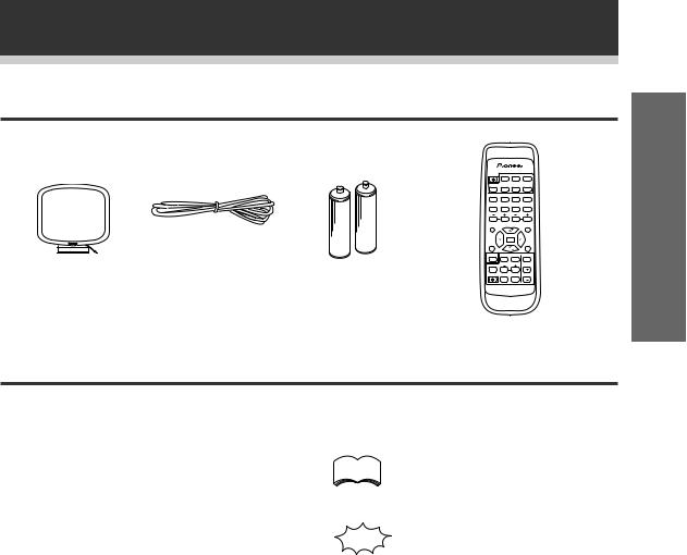
Checking the Supplied Accessories
Please check that you've received the following supplied accessories:
AM loop antenna |
FM wire antenna |
'AA' size IEC R6P |
|
|
batteries (x2) |
Using this Manual
|
SOURCE SELECT |
||
SOURCE |
DVD |
CD |
TUNER |
TV CONT. |
TAPE |
MD |
CD-R |
$ |
$ |
! |
! |
1 |
2 |
3 |
4 |
|
* |
& |
# |
5 |
6 |
7 |
8 |
TV VOL. |
CHANNEL |
||
EFFECT |
STATION |
||
9 |
0 |
|
|
D. ACCESS |
|
|
CLASS |
TOP MENU |
|
|
MENU |
|
|
FQ |
|
RF ATT |
DISP |
||
|
ENTER |
|
|
TEST |
|
|
MPX |
TONE |
|
|
SET UP |
|
|
FQ |
|
SORROUND |
2 |
DSP MODE |
MUTING |
CH. SELECT |
LEVEL |
|
|
RECEIVER |
|
FL |
MASTER |
FUNCTION DIMMER |
VOLUME |
||
AV MULTI-CHANNEL RECEIVER |
Î |
||
REMOTE CONTROL UNIT |
|||
Remote control unit
This manual is for the VSX-409RDS audio/video |
|
The following symbols are used |
|
multi-channel receiver. It is divided into two main |
|
||
|
throughout this manual: |
||
sections: |
|
||
|
|
||
Set up |
memo |
Provides detailed precautions and |
|
This section covers installing your receiver and |
advice on operations, etc. |
||
|
|||
connecting up all the other components in your |
|
|
|
home theater system to it. It also describes how to |
|
|
|
set up a multi-channel speaker system to take full |
|
|
|
advantage of the great surround sound features of |
|
Indicates that display is blinking. |
|
your receiver. |
|
|
|
Operation |
|
|
|
This section shows you how to use every feature of |
|
|
|
the receiver and its remote control unit. It also |
|
|
|
covers using the supplied remote control to operate |
|
|
|
your other Pioneer home theater components. To |
|
|
|
find out more about a specific button, control or |
|
|
|
indicator, see Displays & Controls starting on page |
|
|
|
17. This will point you to the relevant chapter in the |
|
|
|
manual. |
|
|
|
In the Additional Information section (p.38-40) you'll |
|
|
|
find a troubleshooting section and specifications. |
|
|
up Set
5
Introductory Information
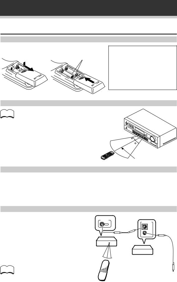
Preparing the Remote Control
Loading the batteries
Dry cell batteries ('AA' size IEC R6P ¥ 2)
CAUTION!
Incorrect use of batteries may result in such hazards as leakage and bursting. Observe the following precautions:
¶Never use new and old batteries together.
¶Insert the plus and minus sides of the batteries properly according to the marks in the battery case.
¶Batteries with the same shape may have different voltages. Do not use different batteries together.
Operating range of remote control unit
memo |
The remote control may not work properly if: |
|
¶There are obstacles between the remote control and the receiver's remote sensor.
¶Direct sunlight or fluorescent light is shining onto
the remote sensor. |
|
¶ The receiver is located near a device that is |
30 |
emitting infrared rays. |
|
¶ The receiver is operated simultaneously with |
30 |
another infrared remote control unit. |
|
7m
Special note on the remote control
Please note that the remote control has two types of buttons, one called FUNCTION and a set of buttons called SOURCE SELECT. Use the FUNCTION button to choose the component you want to listen to (CD, CDR/TAPE, TUNER, etc.) and use the SOURCE SELECT buttons to change which component the remote control itself will operate. Thus, if the VSX-409RDS is in TUNER mode, for example, and you want to listen to your CD player, you need to select the CD mode with the FUNCTION button.
Operating other Pioneer components
By connecting a control cord (optional), you can control other Pioneer equipment using this remote control unit. Point the remote control unit towards the remote sensor of this unit, even when operating other equipment.
The remote control signals are received by the remote sensor of this unit, and sent to the other devices via the CONTROL OUT terminal.
CONTROL
OUT
VSX-409RDS
memo |
You can also control Pioneer components |
|
by pointing the receiver's remote control |
||
|
||
|
directly at the component. This type of |
|
|
operation does not require control cords. |
Remote control unit
CONTROL
IN
OUT
Other Pioneer products with Î mark
Connect to CONTROL IN terminal of other Pioneer products with Î mark.
6
Connecting Your System
Before making or changing the connections, switch off the power switch and disconnect the power cord from the AC outlet.
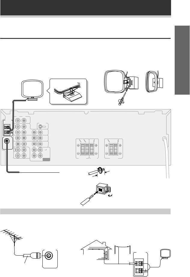
Connecting Antennas
Connect the AM loop antenna and the FM wire antenna as shown below. To improve reception and sound quality, connect external antennas (see Using external antennas, below). Always make sure that the receiver is switched off and unplugged from the wall outlet before making or changing any connections.
AM loop antenna
Assemble the antenna and connect to the receiver. Attach to a wall, etc. (if desired) and face in the direction that gives the best reception.
up Set
R L
AM LOOP |
|
ANTENNA IN |
CD |
CONTROL
O |
|
|
|
U |
|
|
OUT |
T |
|
|
|
|
VCR/ |
|
|
|
DVR |
|
|
IN |
|
IN |
OUT |
FM ANTENNA IN |
TV/ |
IN |
TO |
MONITOR |
|||
|
SAT |
|
TV |
FM |
|
DVD |
|
SUB |
R |
L |
UNBAL |
IN |
/LD |
IN |
WOOFER |
|
|
|
FRONT |
PREOUT |
|
|
||
75Ω |
|
|
|
|||
|
|
|
|
|||
|
R |
OUT |
|
SURROUND |
|
|
|
E |
R |
L |
|
|
|
|
C |
CD-R |
|
|
||
|
|
/TAPE |
|
|
|
|
|
P |
/MD |
|
|
|
|
|
L |
IN |
|
CENTER |
|
|
|
A |
|
FRONT |
CENTER |
||
|
Y |
|
SUB |
|
||
|
|
|
DVD 5.1 CH |
SPEAKERS |
SPEAKER |
|
|
|
|
WOOFER |
INPUT |
|
|
R |
L |
SURROUND |
|
SPEAKERS |
|
FM wire antenna |
10mm |
Connect the FM wire antenna and fully extend |
Antenna snap connectors |
vertically along a window frame, etc. |
Twist the exposed wire strands |
|
together and insert into the hole, |
|
then snap the connector shut. |
Using external antennas
7 To improve FM reception 7 To improve AM reception
Connect an external FM antenna.
Connect a 5–6 meter length of vinyl-coated wire to the AM antenna terminal without disconnecting the supplied AM loop antenna.
For the best possible reception, suspend horizontally outdoors.
Outdoor antenna
75 Ω coaxial cable
FM ANTENNA
FM
UNBAL 75Ω
AM LOOP
ANTENNA
Indoor antenna (Vinyl-coated wire)
5–6m
7
Connecting Your System
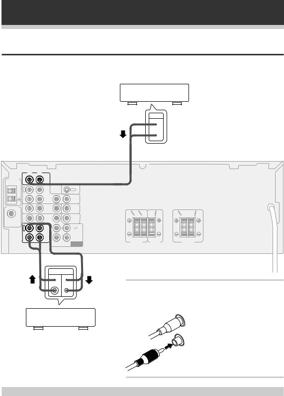
Connecting Audio Components
Connect your audio components as shown below. When connecting equipment, always make sure the power switched off and the power cord is disconnected from the wall outlet.
|
R |
L |
|
|
|
AM LOOP |
IN |
CD |
|
|
|
ANTENNA |
|
|
|||
|
|
|
|
CONTROL |
|
|
O |
|
|
|
|
|
U |
|
|
OUT |
|
|
T |
|
|
|
|
|
|
VCR/ |
|
|
|
|
|
DVR |
|
|
|
|
IN |
|
IN |
|
|
FM ANTENNA |
IN |
TV/ |
IN |
TO |
|
MONITOR |
|||||
|
|
SAT |
|
TV |
|
FM |
|
DVD |
|
SUB |
|
IN |
/LD |
IN |
WOOFER |
||
UNBAL |
|||||
|
FRONT |
PREOUT |
|||
75Ω |
|
||||
|
|
||||
|
R |
OUT |
|
SURROUND |
|
|
E |
R |
L |
||
|
C |
CD-R |
|||
|
|
/TAPE |
|
|
|
|
P |
/MD |
|
|
|
|
L |
IN |
|
CENTER |
|
|
A |
|
|||
|
Y |
|
SUB |
|
|
|
|
|
DVD 5.1 CH |
||
|
|
|
WOOFER |
INPUT |
|
PLAY REC
 L
L 
R 
CD-R , Cassette deck
MD , DAT etc.
CD player
OUT
 L
L
 R
R
R |
L |
R |
L |
FRONT |
CENTER |
SURROUND |
|
SPEAKERS |
SPEAKER |
SPEAKERS |
|
Audio cords
Use good quality audio cords with RCA/phono plugs at each end (not supplied) to connect your audio components.
L |
Connect red plugs to R (right) and |
|
|
|
white plugs to L (left) terminals. |
R |
Be sure to push home the plugs into |
|
|
|
their sockets. |
Cassette deck placement
Depending on where the cassette deck is placed, noise caused by leakage flux from the transformer in the receiver may occur during playback. If you experience noise, move the cassette deck farther away from the receiver.
8
Connecting Your System
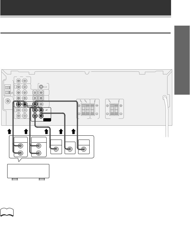
Connecting DVD 5.1 Channel Components
DVD and LD discs are often compatible with both 2 channel and 5.1 channel audio output formats. Refer to page 21 for more information on how to switch between the two input methods.
Connections can be made from a DVD player, multi channel decoder equipped with 5.1 analogue outputs to the 5.1 analogue inputs on this unit. When connecting equipment, always make sure the power switched off and the power cord is disconnected from the wall outlet.When connecting equipment, always make sure the power switched off and the power cord is disconnected from the wall outlet.
|
R |
L |
|
|
AM LOOP |
IN |
CD |
|
|
ANTENNA |
|
|
||
|
|
|
|
CONTROL |
|
O |
|
|
|
|
U |
|
|
OUT |
|
T |
|
|
|
|
|
VCR/ |
|
|
|
|
DVR |
|
|
|
IN |
|
IN |
|
FM ANTENNA |
IN |
TV/ |
IN |
TO |
MONITOR |
||||
|
|
SAT |
|
TV |
FM |
|
DVD |
|
SUB |
R |
L |
IN |
/LD |
IN |
WOOFER |
|
|
|
UNBAL |
|
|
||||
|
FRONT |
PREOUT |
|
|
||
75Ω |
|
|
|
|||
|
|
|
|
|||
|
R |
OUT |
|
SURROUND |
|
|
|
E |
R |
L |
|
|
|
|
C |
CD-R |
|
|
||
|
|
/TAPE |
|
|
|
|
|
P |
/MD |
|
|
|
|
|
L |
IN |
|
CENTER |
|
|
|
A |
|
FRONT |
CENTER |
||
|
Y |
|
SUB |
|
||
|
|
|
DVD 5.1 CH |
SPEAKERS |
SPEAKER |
|
|
|
|
WOOFER |
INPUT |
|
|
R |
L |
SURROUND |
|
SPEAKERS |
|
FRONT |
SURROUND |
|
|
OUT PUT |
OUT PUT |
SUB |
VODEO |
L |
L |
WOOFER CENTER |
OUT |
|
|
||
R |
R |
|
|
Components equipped with 5.1 channel analogue output jacks
memo
The 5.1 channel input can only be used when DVD 5.1 CH is selected.
up Set
Operation
9
Connecting Your System
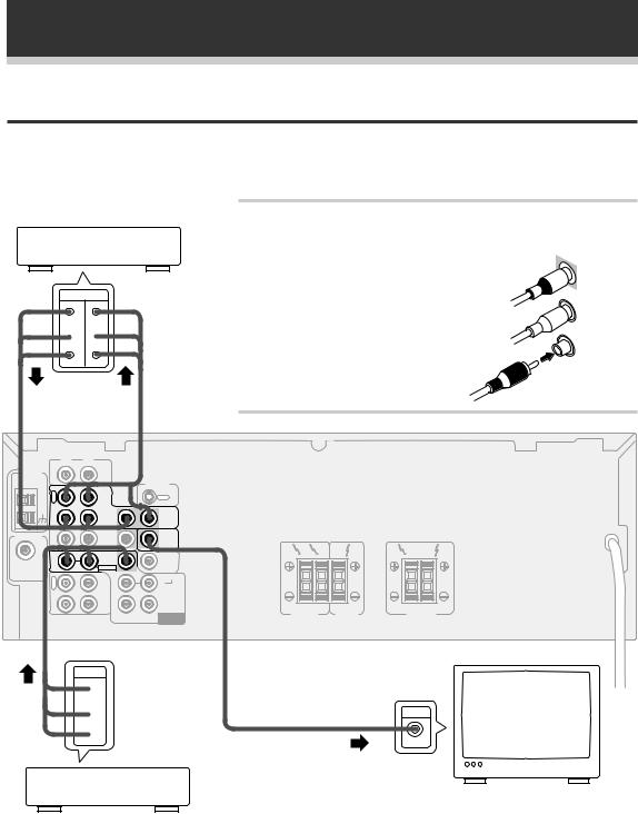
Connecting Video Components
Connect your video components as shown below. When connecting equipment, make sure the power is switched off and the power cord disconnected from the wall outlet.
VCR, DVR, etc.
OUT IN
 V
V 
 L
L 
 R
R 
|
R |
L |
|
|
AM LOOP |
IN |
CD |
|
|
ANTENNA |
|
|
||
|
|
|
|
CONTROL |
|
O |
|
|
|
|
U |
|
|
OUT |
|
T |
|
|
|
|
|
VCR/ |
|
|
|
|
DVR |
|
|
|
IN |
|
IN |
OUT |
FM ANTENNA |
IN |
TV/ |
IN |
TO |
MONITOR |
||||
|
|
SAT |
|
TV |
FM |
IN |
DVD |
IN |
|
UNBAL |
/LD |
|
||
75Ω |
|
FRONT |
|
|
|
R |
OUT |
|
SURROUND |
|
E |
R |
L |
|
|
C |
CD-R |
||
|
|
/TAPE |
|
|
|
P |
/MD |
|
|
|
L |
IN |
|
CENTER |
|
A |
|
||
|
Y |
|
SUB |
|
|
|
|
DVD 5.1 CH |
|
|
|
|
WOOFER |
INPUT |
OUT
 V
V
 L
L
 R
R
Audio/Video cords
Use good quality audio/video cords with RCA/phono plugs at each end (not supplied) to connect the video components and a video cord to connect the monitor/TV. 
Connect red plugs to R (right), white plugs to |
IN |
|
L (left), and the yellow plugs to VIDEO. |
||
|
Be sure to push home the plugs into their sockets.
R |
L |
R |
L |
FRONT |
CENTER |
SURROUND |
|
SPEAKERS |
SPEAKER |
SPEAKERS |
|
IN |
TV |
monitor
VIDEO
DVD , LD player
10

Connecting Your System
Connecting Speakers
Connect your speakers as shown below. Be sure to connect each speaker to the appropriate speaker terminals, and also to connect the positive and negative terminals correctly (positive to positive, negative to negative). When connecting equipment, always make sure the power switched off and the power cord is disconnected from the wall outlet.
• Use speakers with a nominal impedance of 8 Ω to 16 Ω.
When connecting equipment, always make sure the power switched off and the power cord is disconnected from the wall outlet.
Front |
Powered |
Front |
sub-woofer |
||
(left) |
|
(right) |
|
|
Center |
up Set
INPUT
|
R |
L |
|
|
AM LOOP |
IN |
CD |
|
|
ANTENNA |
|
|
||
|
|
|
|
CONTROL |
|
O |
|
|
|
|
U |
|
|
OUT |
|
T |
|
|
|
|
|
VCR/ |
|
|
|
|
DVR |
|
|
|
IN |
|
IN |
OUT |
FM ANTENNA |
IN |
TV/ |
IN |
TO |
MONITOR |
||||
|
|
SAT |
|
TV |
|
|
|
|
FM |
|
DVD |
|
SUB |
R |
L |
UNBAL |
IN |
/LD |
IN |
WOOFER |
|
|
75Ω |
|
FRONT |
PREOUT |
|
|
|
|
|
|
|
|||
|
R |
OUT |
|
SURROUND |
|
|
|
E |
R |
L |
|
|
|
|
C |
CD-R |
|
|
||
|
|
/TAPE |
|
|
|
|
|
P |
/MD |
|
|
|
|
|
L |
IN |
|
CENTER |
|
|
|
A |
|
FRONT |
CENTER |
||
|
Y |
|
SUB |
|
||
|
|
|
DVD 5.1 CH |
SPEAKERS |
SPEAKER |
|
|
|
|
WOOFER |
INPUT |
|
|
R |
L |
SURROUND |
|
SPEAKERS |
|
Surround |
Surround |
(left) |
(right) |
Operation
Speaker terminals
Use good quality speaker wire to connect the speakers to the receiver.
1Twist around 10 mm of bare wire strands together. 2Unclip the speaker terminal and insert the wire.
3 Snap shut the speaker terminal to secure.
ª ·
11
Connecting Your System
Hints on speaker placement
Speakers are usually designed with a particular placement in mind. Some are designed to be floorstanding, while others should be placed on stands to sound their best. Some should be placed near a wall; others should be placed away from walls. Follow the guidelines on placement that the speaker manufacturer provided with your particular speakers to get the most out of them.
•Place the front left and right speakers at equal distances from the TV.
•When placing speakers near the TV, we recommend using magnetically shielded speakers to prevent possible interference, such as discoloration of the picture when the TV is switched on. If you do not have magnetically shielded speakers and notice discoloration of the TV picture, move the speakers farther away from the TV.
•Install the center speaker above or below the TV so that the sound of the center channel is localized at the TV screen.
CAUTION!
If you choose to install the center speaker on top of the TV, be sure to secure it with putty, or by other suitable means, to reduce the risk of damage or injury resulting from the speaker falling from the TV in the event of external shocks such as earthquakes.
•If possible, install the surround speakers slightly above ear level.
•Try not to install the surround speakers farther away from the listening position than the front and center speakers. Doing so can weaken the surround sound effect.
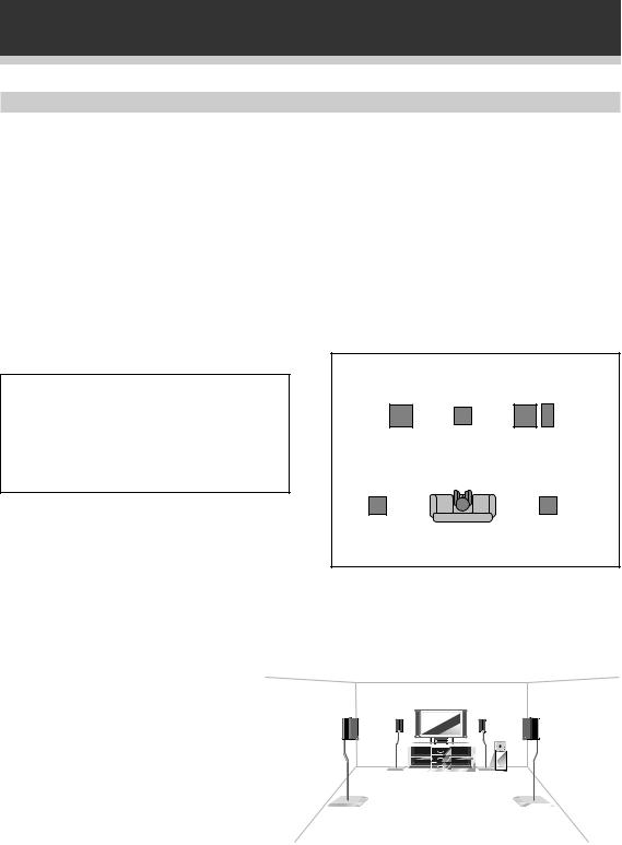
To achieve the best possible surround sound, install your speakers as shown below. Be sure all speakers are installed securely to prevent accidents and improve sound quality.
Front |
|
Front |
Left |
Center |
Right |
|
|
Sub
Woofer
Surround |
Surround |
Left |
Right |
Listening
Position
3-D View of speaker set up
12
 Loading...