

Page 1
ORDER NO.
RRV1966
AUDIO/VIDEO MULTI-CHANNEL RECEIVER
VSX-11
Refer to the service manual RRV1911 for VSX-D507S/KUXJI.
THIS MANUAL IS APPLICABLE TO THE FOLLOWING MODEL(S) AND TYPE(S).
Type
KUXJI/CA O AC120V
Model
VSX11
Power Requirement Remarks
CONTENTS
1. CONTRAST OF MISCELLANEOUS PARTS .....2
2. SCHEMATIC DIAGRAM.....................................6
3. PCB CONNECTION DIAGRAM .......................16
4. GENERAL INFORMATION .............................. 17
4.1 ATTACHING THE DOOR PANEL .............. 17
PIONEER ELECTRONIC CORPORATION
PIONEER ELECTRONICS SERVICE, INC.
PIONEER ELECTRONIC (EUROPE) N.V .
PIONEER ELECTRONICS ASIACENTRE PTE. LTD. 501 Orchard Road, #10-00 Wheelock Place, Singapore 238880
CC
C
PIONEER ELECTRONIC CORPORATION 1998
CC
P.O. Box 1760, Long Beach, CA 90801-1760, U.S.A.
Haven 1087, Keetberglaan 1, 9120 Melsele, Belgium
4-1, Meguro 1-Chome, Meguro-ku, Tokyo 153-8654, Japan
T–ZZY MAY 1998 Printed in Japan
Page 2
VSX-11
1. CONTRAST OF MISCELLANEOUS PARTS
NOTES : ÷ Parts marked by “ NSP ” are generally unavailable because they are not in our Master Spare Parts List.
÷ The mark found on some component parts indicates the importance of the safety factor of the part.
Therefore, when replacing,be sure to use parts of identical designation.
÷ Reference Nos. indicate the pages and Nos. in the service manual for the base model.
÷ Screw adjacent to ∞ mark on the product are used for disassembly.
÷ When ordering resistors, first convert resistance values into code form as shown in the following examples.
Ex. 1 When there are 2 effective digits (any digit apart from 0), such as 560 ohm and 47k ohm (tolerance is shown by
J = 5%, and K = 10%).
560 Ω = 56 × 10
47k Ω = 47 × 10
0.5 Ω = R50 ...................................................................... RN2H Â 5 0 K
1 Ω = 1R0 ......................................................................... RS1P 1 Â 0 K
Ex. 2 When there are 3 effective digits (such as in high precision metal film resistors).
5.62k Ω = 562 × 10
CONTRAST TABLE
VSX-11/KUXJI/CA and VSX-D507S/KUXJI are constructed the same except for the following :
Ref. No.
NSP MOTHER Assy AWK7432 AWK7437
P5-1 INPUT Assy AWX7102 AWX7106
P5-2 R/C SP&6CH Assy AWX7092 Not used
P5-3 REG Assy AWX7093 AWX7203
NSP FRONT & PS Assy AWK7433 AWK7438
P5-6 POWER SUPPLY Assy AWX7096 AWX7204
P5-7 VIDEO Assy AWX7105 AWX7110
P6-2 FL&UCOM Assy AWX7104 AWX7107
P6-4 VOLUME Assy AWX7097 AWX7205
NSP ELITE ASSY Not used AWK7439
P3-3 Operating Instructions (English) ARB7134 ARB7135
P3-4 NSP Warranty Card ARY1051 ARY7007
P3-11 Packing Case AHD7554 AHD7556
P5-11 Power Transformer T1 (AC120V) ATS7207 ATS7208
P5-17 Flat Flexible Cable (12P) ADD7090 ADD7091
P5-19 Rear Panel ANC7624 ANC7626
P5-26 Foot Assy (Rear Side) REC1263 Not used
P5-30 Screw ABA7043 ABA1022
Symbol and DescriptionMark VSX-11
ASSEMBLIES
HP&FAV Assy AWX7103 Not used
LARGE FSP Assy Not used AWX7108 No.1
LAGE RCSP Assy Not used AWX7109 No.2
HP ASSY Not used AWX7159 No.3
PACKING
EXTERIOR SECTION
Screw Not used ABA1193 No.4
Screw Not used ABA7023 No.5
Screw Not used ABA7035 No.6
FCC Label Not used VRW1725 No.7
DOC Label Not used VRW1726 No.8
1
= 561................................................... RD1/4PU 5 6 1 J
3
= 473 .................................................. RD1/4PU 4 7 3 J
1
= 5621 ........................................... RN1/4PC 5 6 2 1 F
Part No.
VSX-D507S
KUXJI
KUXJI/CA
Remarks
Fuse (FU4: 10A) Not used REK1087 No.9
P6-16 Sub Panel AAP7041 AAP7039
P6-17 Front Panel AMB7486 AMB7487
P6-24 Housing 5P Shield ADX7238 Not used
:
Note
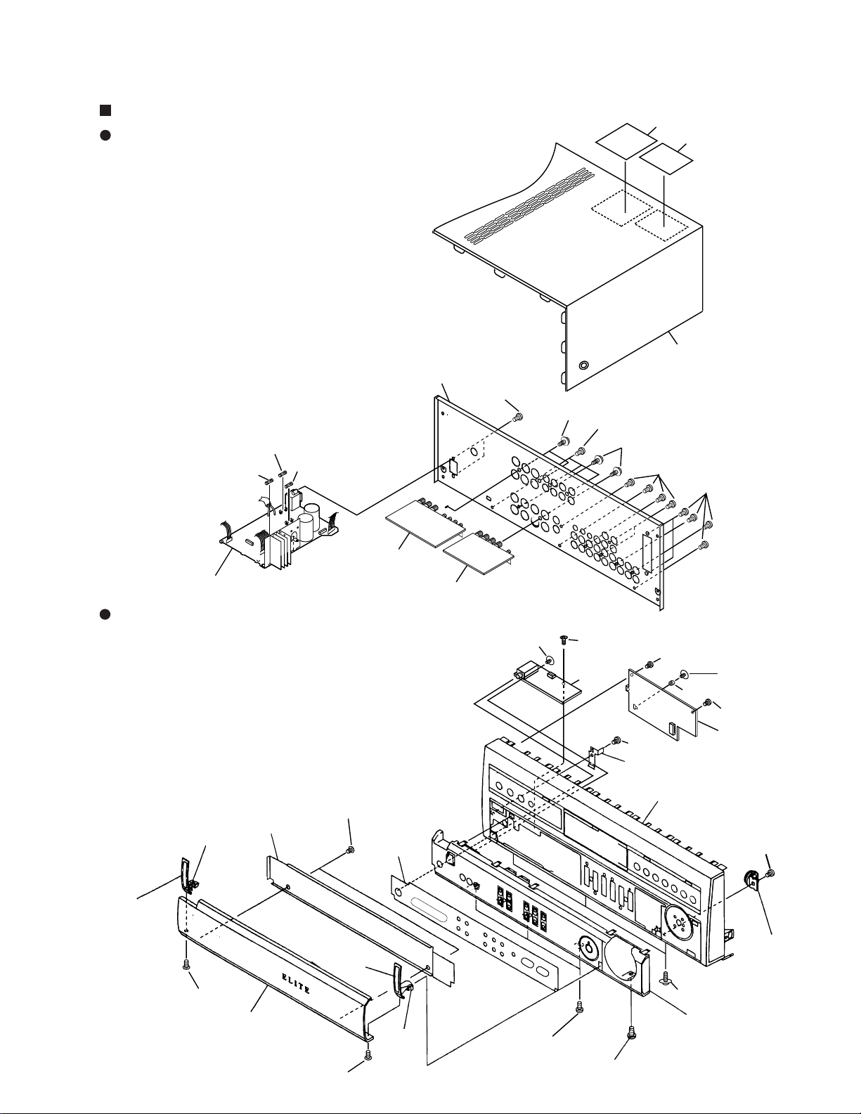
The numbers in the remarks column correspond to the numbers on the exploded diagram, Refer to “EXPLODED VIEWS”.
For ASSEMBLIES, Refer to “ CONTRAST OF PCB ASSEMBLES” and “2. SCHEMATIC AND PCB DIAGRAMS”.
FRONT PANEL SECTION
Plate Spring Not used ABK7011 No.10
Door Hinge L Not used AMR7171 No.11
Door Hinge R Not used AMR7172 No.12
Door Panel Not used AAK7561 No.13
PVC Panel Not used AAK7534 No.14
Dumper Assy Not used AXA7046 No.15
Door Plate Not used ANG7187 No.16
Collar Spacer Not used AEC7146 No.17
2
Page 3
VSX-11
No.4
No.4
BBT30P080FCC
BBT30P080FCC
BBT30P080FCC
BBT30P080FCC
Rear panel
No.10
No.2
No.7
No.8
No.1
BPZ30P080FMC
Front Panel
BPZ30P080FMC
No.15
Sub Panel
BPZ30P080FZK
BPZ30P080FZK
No.12
No.5
No.13
No.5
No.11
No.16
No.14
No.5
(D-faced tape)
(D-faced tape)
No.6
BPZ30P080FMC
BPZ30P080FMC
ABA7009
No.17
No.3
Power SW Assy
ABA7046
Screw
ABA7046
Screw
Screw
Screw
Screw
Screw
Screw
Screw
Screw
Screw
Screw
Screw
Screw
Front
Bonnet Case
No.9
Power Supply Assy
Fuse
FU2: 6.3A
Fuse
FU1: 10A
EXPLODED VIEWS
EXTERIOR SECTION
FRONT PANEL SECTION
3
Page 4
VSX-11
CONTRAST OF PCB ASSEMBLIES
E F 1/2
E F 2/2
INPUT ASSY
AWX7106 and AWX7102 are constructed the same except for the following :
Symbol and Description
IC151, IC181, IC201, IC221 NJM4558D UPC4570C
Q101, Q102 Not used 2SC2878
C151, C152 CEAT2R2M50 ACH7004
C153, C154 CEAT221M16 ACH7096
C155, C156, C260, C265, C269, C273 CEAT101M10 CEAT101M16
C181, C182, C189, C190 CEAT4R7M50 ACH7003
C203, C361 CEAT221M10 ACH7096
C211, C219 CEAT4R7M50 CEZA4R7M50
C272, C294 CCCSL221J50 CCCSL221K2H
C313, C314, C1313, C1314 CEAT1R0M50 CEAT1R0M2A
C323, C324, C1323, C1324, C1365 CEANP2R2M50 CEANP2R2M2A
R119, R120 Not used RD1/4PU122J
R121, R122 Not used RD1/4PU102J
R123, R124 Not used RD1/4PU223J
R145, R146 RD1/4PU272J RDR1/6PU272J
R147, R148 RD1/4PU182J RDR1/6PU182J
CN108 PLUG 5P KM250MA5 Not used
CN114 PIN JACK 4P AKB7015 Not used
CN351 PIN JACK 6P AKE7006 Not used
NSP J19 JUMPER WIRE Not used DYY03-125-2651
AWX7102
Part No.
AWX7106
(2.2µF/50V)
(220µF/16V)
(4.7µF/50V)
(220µF/16V)
RemarksMark
NSP J20 JUMPER WIRE Not used DYY08-100-2651
G F
114 PIN JACK 6P Not used AKB7012
353 CONNECTOR ASSY 3P Not used 51052-0300
354 CONNECTOR ASSY 8P Not used 51052-0800
FL&UCOM ASSY
AWX7107 and AWX7104 are constructed the same except for the following :
Mark
REG ASSY
B
Symbol and Description
D621 1SS254 Not used
D622 Not used 1SS254
R654 RD1/4PU103J Not used
AWX7104
Part No.
AWX7107
AWX7203 and AWX7093 are constructed the same except for the following :
Symbol and Description
C503, C504 CEAT101M16 CEBA101M16
C506 CEAT101M10 CEAT101M16
POWER SUPPLY ASSY
I F
AWX7093
Part No.
AWX7203
AWX7204 and AWX7096 are constructed the same except for the following :
Mark
Symbol and Description
C707, C708 CEAT472M25 ACH7095
C715, C716 ACH7018 ACH7094
H707, H708 (FUSE CLIP) Not used AKR1004
AWX7096
(8200µF/71V) (10000µF/71V)
Part No.
AWX7204
(4700µF/25V)
Remarks
RemarksMark
Remarks
4
Page 5
VIDEO ASSY
L F
AWX7110 and AWX7105 are constructed the same except for the following :
Part No.
Q933 Not used 2SA933S
D934- D938 Not used 1SS254
C932 Not used CKCYB682K50
R936, R937 Not used RD1/4PU224J
R938, R939, R941 Not used RD1/4PU102J
R940 Not used RD1/4PU103J
933 MINI JACK Not used AKN7002
VOLUME ASSY
M
Symbol and Description
AWX7105
AWX7205 and AWX7097 are constructed the same except for the following :
Symbol and Description
Q806, Q808 2SC2603 2SC5389
Q805, Q807 2SA1115 2SA1993
C805, C806 CEAT4R7M50 ACH7003
C809, C810 CEAT4R7M50 CEZA4R7M50
C813, C814, C817, C818 CEAT4R7M50 ACH7003
C822, C826 CEAT4R7M50 CEZA4R7M50
AWX7097
Part No.
AWX7110
AWX7205
(4.7µF/50V)
(4.7µF/50V)
VSX-11
RemarksMark
RemarksMark
PCB PARTS LIST
Mark No. Description Part No.
LARGE FSP ASSY
N
SEMICONDUCTORS
Q1001, Q1002 2SC2878
RESISTORS
All Resistors RD1/4PU J
OTHERS
CN1001 SPEAKER TERMINAL 8P AKE7036
CN1002 JUMPER CONNECTOR 8P KPD8
CN1003 JUMPER CONNECTOR 3P KPD3
CN1004 PINJACK 2P AKB7008
LARGE RCSP ASSY
P
SEMICONDUCTORS
IC1071, IC1072 NJM4558D
Q1051 KRA101M
Q1052 2SC1740S
Q1055 2SC2878
D1051, D1052 1SS254
COILS AND FILTERS
L1051, L1053, L1054 (0.7µH
SWITCHES AND RELAYS
RY1051, RY1052 ASR7001
CAPACITORS
C1071- C1074 CEAT2R2M50
C1051, C1053, C1054 CFTLA104J50
C1055- C1057, C1081, C1082 CGCYX473M16
C1075- C1078 CKPUYY103M16
)
ATH1004
Mark No. Description Part No.
RESISTORS
R1051, R1053, R1054 RD1/4PMF100J
R1055, R1057, R1058 RS1LMF4R7J
Other Resistors RD1/4PU J
OTHERS
1051 CABLE HOLDER 3P 51052-0300
CN1051 FFC CONNCTOR 12P XKP3012
CN1052 SPEAKER TERMINAL 6P AKE7037
CN1053, CN1054 PINJACK 4P AKB7087
CN1055 JUMPER CONNECTOR 6P KPD6
J17 JUMPER WIRE DYY03-200-2651
HP ASSY
O
SEMICONDUCTORS
Q1101, Q1102 2SC2878
CAPACITORS
C1101 CGCYX104M16
RESISTORS
R1103, R1104 RD1/4PU103J
Other Resistors RD1/2PM J
OTHERS
1102 GROUND PLATE VNF-091
CN1101 CONNECTOR 4P 52045-0445
JA1101 HEADPHONE JACK RKN1002
5
Page 6
1
VSX-11
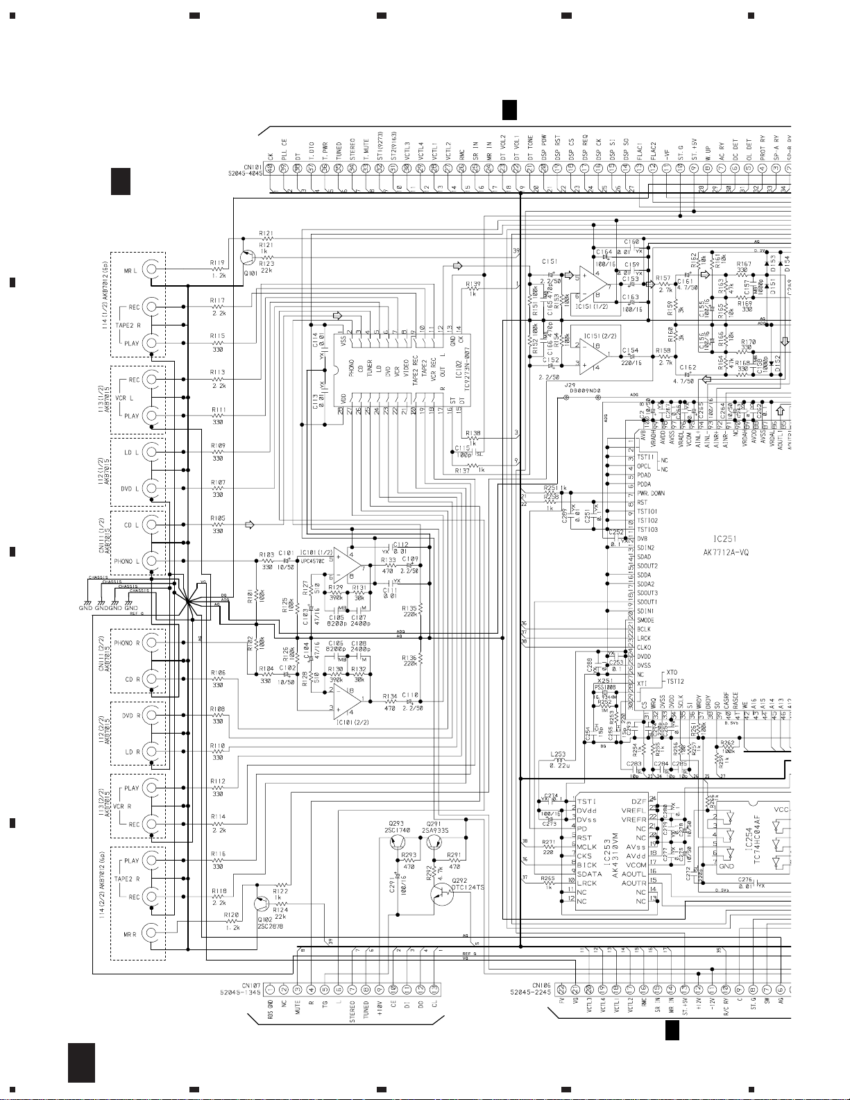
2. SCHEMATIC DIAGRAM
2.1 INPUT ASSY (1/2)
A
E
F 1/2
INPUT ASSY
(AWX7106)
23
G
F 1/2
CN601
4
2SC2878
B
(ACH7004)
UPC4570C
(ACH7004)
C153:
220/16
(ACH7096)
(ACH7096)
C
100p
SL
D
6
E F 1/2
1234
TO TUNER ASSY
SMALL SIGNAL BLOCK
L
F1/2
CN901
Page 7

5
678
VSX-11
NOTE: When ordering service parts, be sure to refer to
B
502
“PARTS LIST of EXPLODED VIEWS” or “PCB
PARTS LIST”.
(ACH7003)
(ACH7003)
UPC4570C
1500p
: AUDIO SIGNAL ROUTE
Direct OFF
PRO Logic OFF
5-D OFF
DSP Mode OFF
CD Input
(ACH7003)
(ACH7096)
(ACH7003)
UPC4570C
1500p
5.6k5.6k 4.3k
24k
A
B
N901
CN801
M
C
2.7k
UPC4570C
15k15k
CN802
M
E
F 2/2
D
581
F
E F 1/2
5
6
7
8
7
Page 8

1
VSX-11
2.2 INPUT ASSY (2/2)
A
B
23
IC301 (1/2)
IC301 (2/2)
4
IC303
F 1/2
E
IC302 (1/2)
C
IC302 (2/2)
(ACH7096)
D
E
F 1/2
8
E F 2/2
1234
Page 9

5
678
VSX-11
A
E
F 2/2
INPUT ASSY
(AWX7106)
A_MUTE
L
R
51052-0300
353
POWER AMP BLOCK
51052-0800
354
+BL
+AL
-BL
-BR
-AL
-AR
+BR
+AR
B
E
F 1/2
E
F 1/2
1051
P
: AUDIO SIGNAL ROUTE
Direct OFF
PRO Logic OFF
5-D OFF
DSP Mode OFF
CD Input
J19
DYY03-125-2651
J20
DYY08-100-2651
A_MUTE
E
F 1/2
L
R
+BL
+AL
-BL
-BR
-AL
-AR
+BR
+AR
N
LARGE FSP ASSY
(AWX7108)
C
D
N
5
6
7
E F 2/2
8
9
Page 10

1
VSX-11
2.3 FL&UCOM ASSY
23
4
F 1/2
CN101
E
A
B
CN803
M
C
HP ASSY
O
(AWX7159)
D
H
CN981
10
G F
O
1234
Page 11

5
FL&UCOM ASSY
G
F
(AWX7107)
FRONT BLOCK
678
VSX-11
A
B
FL&UCOM ASSY
S601 : TONE/BALANCE +/R
S602 : TONE/BALANCE –/L
S603 : TAPE2 MONITOR
S604 : PHONO
S605 : FM/AM
S606 : CD
S607 : LD/SAT
S608 : DVD/TV
S609 : VCR/TAPE1
S610 : TONE/BALANCE SELECT
S611 : CLASS
S612 : ST/FEQ. –
S613 : ST/FEQ. TUNING SELECT
S614 : MEMORY
S615 : ST/FEQ. +
S616 : DIGITAL NR(VSX-D507S)
MUTING(VSX-D457)
S617 : MPX MODE
S618 : DIRECT
S619 : SPEAKERS
S620 : LOUDNESS
C
D
5
6
7
8
G F
11
Page 12

1
VSX-11
2.4 POWER SUPPLY ASSY
A
POWER SUPPLY ASSY
S711 : IMPEDANCE SELECTOR
CN582
F
B
23
10/50
C739
4
CN1055
P
KM200TA13
CN572
D
C
POWER SUPPLY BLOCK
VEK1026
(6.3A/125V)
ASR7016
REK1087
(10A/125V)
J22
J
J21
J
AC Power cord
PDG1055
AC120V 60Hz
LIVE
D
NEUTRAL
• NOTE FOR FUSE REPLACEMENT
CAUTION -
FOR CONTINUED PROTECTION AGAINST RISK OF FIRE.
REPLACE WITH SAME TYPE AND RATINGS ONLY.
12
I F
1234
Page 13

5
POWER SUPPLY ASSY
I
F
(AWX7204)
678
VSX-11
A
(ACH7094)
(ACH7094)
(ACH7095) (ACH7095)
H707
AKR1004
REK1087
(10A/125V)
FU4
H708
K
K
951
B
952
C
D
13
I F
5
6
7
8
Page 14

1
VSX-11
2.5 VIDEO ASSY
A
B
23
VIDEO ASSY
L
F
(AWX7110)
4
VIDEO & SR BLOCK
C
D
14
CN1051
P
E
L F
1234
F 1/2
CN106
Page 15

1
234
VSX-11
2.6 LARGE RCSP ASSY
LARGE RCSP ASSY
P
F 2/2 CN352
E
(AWX7109)
I
F 713
A
B
F CN902
L
C
D
P
1
2
3
4
15
Page 16

1
23
VSX-11
3. PCB CONNECTION DIAGRAM
3.1 LAEGE FSP, HP and LARGE RCSP ASSY
A
B
NOTE FOR PCB DIAGRAMS:
1. Part numbers in PCB diagrams match those in the
schematic diagrams.
2. A comparison between the main parts of PCB and
schematic diagrams is shown below.
Symbol in PCB
Diagrams
3. The parts mounted on this PCB include all necessary
parts for several destination.
For further information for respective destinations,
be sure to check with the schematic diagram.
4. Viewpoint of PCB diagrams
Symbol in Schematic
Diagrams
BCE
BCE
BCEBCE
BCE
DGSDGS
DGS
P. C. Board Chip Part
BCE
CapacitorConnector
Part Name
Transistor
Transistor
with resistor
Field effect
transistor
Resistor
array
3-terminal
regulator
SIDE A
SIDE B
CN603
G
HP ASSY
O
Q1102 Q1101
LARGE FSP ASSY
N
E
E
4
354
353
Q1002 Q1001
LARGE RCSP ASSY
P
C
D
IC1072 IC1071 Q1055 Q1051 Q1052
713
I
SIDE A
L E
16
N
(ANP7236-B)
CN352CN902
O P
1234
Page 17

4. GENERAL INFORMATION
4.1 ATTACHING THE DOOR PANEL
1
Slide the Door Panel slantways.
2
Rotate it so that it is horizontal.
3
Push it straight in.
3
2
VSX-11
4
Move it downwards a little,and push in with bending it.
4
4
17
 Loading...