

Page 1

AUDIO/VIDEO MUL TICHANNEL
AMPLIFIER
VSA-E03
Operating Instructions
Page 2
Thank you for buying this Pioneer product.
Please read through these operating instructions so you will know
how to operate your model properly. After you have finished
reading the instructions, put them away in a safe place for future
reference.
In some countries or regions, the shape of the power plug and
power outlet may sometimes differ from that shown in the
explanatory drawings. However the method of connecting and
operating the unit is the same.
WARNING: TO PREVENT FIRE OR SHOCK HAZARD, DO NOT
EXPOSE THIS APPLIANCE TO RAIN OR MOISTURE.
This product complies with the Low Voltage Directive
(73/23/EEC), EMC Directives (89/336/EEC, 92/31/EEC) and
CE Marking Directive (93/68/EEC).
THE POWER SWITCH IS SECONDARY CONNECTED AND
THEREFORE DOES NOT SEPARATE THE UNIT FROM MAINS
POWER IN THE STANDBY POSITION.
IMPORTANT
CAUTION
RISK OF ELECTRIC SHOCK
DO NOT OPEN
The lightning flash with arrowhead symbol, within
an equilateral triangle, is intended to alert the
user to the presence of uninsulated "dangerous
voltage" within the product's enclosure that may
be of sufficient magnitude to constitute a risk of
electric shock to persons.
CAUTION:
TO PREVENT THE RISK OF ELECTRIC SHOCK, DO
NOT REMOVE COVER (OR BACK). NO USER-SERVICEABLE PARTS INSIDE. REFER SERVICING TO
QUALIFIED SERVICE PERSONNEL.
VENTILATION
÷ When installing this unit, make sure to leave space
around the unit for ventilation to improve heat
radiation (at least 60 cm at top, 10 cm at rear, and 30
cm at each side). If not enough space is provided
between the unit and walls or other equipment, heat
will build up inside, interfering with performance or
causing malfunctions.
÷ Do not place on a thick carpet, bed, sofa or fabric
having a thick pile. Do not cover with fabric or other
covering.
Anything that blocks ventilation will cause internal
temperature to rise, which may lead to breakdown or
fire hazard.
The exclamation point within an equilateral
triangle is intended to alert the user to the presence
of important operating and maintenance
(servicing) instructions in the literature
accompanying the appliance.
Power cord CAUTION!
Handle the power cord by the plug. Do not pull out the
plug by tugging the cord and never touch the power cord
when your hands are wet as this could cause a short
circuit or electric shock. Do not place the unit, a piece of
furniture, etc., on the power cord, or pinch the cord.
Never make a knot in the cord or tie it with other cords.
The power cords should be routed such that they are not
likely to be stepped on. A damaged power cord can
cause a fire or give you an electrical shock. Check the
power cord once in a while. When you find it damaged,
ask your nearest PIONEER authorized service center or
your dealer for a replacement.
IMPORTANT
FOR USE IN THE UNITED
KINGDOM
The wires in this mains lead are coloured in
accordance with the following code :
If the plug provided is unsuitable for your socket
outlets, the plug must be cut off and a suitable plug
fitted.
Blue :Neutral
Brown :live
The cut-off plug should be disposed of and must not be
inserted into any 13 amp socket as this can result in electric
shock. The plug or adaptor or the distribution panel should
be provided with 5 amp fuse. As the colours of the wires in
the mains lead of this appliance may not correspond with
coloured markings identifying the terminals in your plug,
proceed as follows:
The wire which is coloured blue must be connected to the
terminal which is marked with the letter N or coloured black.
The wire which is coloured brown must be connected to
the terminal which is marked with the letter L or coloured
red.
Maintenance of External Surfaces
• Use a polishing cloth or dry cloth to wipe off dust
and dirt.
• When the surfaces are dirty, wipe with a soft cloth
dipped in some neutral cleanser diluted five or six
times with water, and wrung out well, and then wipe
again with a dry cloth. Do not use furniture wax or
cleaners.
• Never use thinners, benzine, insecticide sprays or
other chemicals on or near this unit, since these will
corrode the surfaces.
Do not connect either wire to the earth terminal of a
three pin plug.
NOTE
After replacing or changing a fuse, the fuse cover in the
plug must be replaced with a fuse cover which corresponds to the colour of the insert in the base of the plug
or the word that is embossed on the base of the plug,
and the appliance must not be used without a fuse cover.
If lost, replacement fuse covers can be obtained from
your dealer.
Only 5 A fuses approved by B.S.I. or A.S.T.A. to B.S.
1362 should be used.
2
En
Page 3

Table of Contents
Introductory Information............................................................ 5
Checking the Supplied Accessories.......................................................... 5
How to Use This Manual ...........................................................................5
Preparing the Remote Control ..................................................................5
When Making Cable Connections............................................................. 6
Connections................................................................................. 7
Audio Components Connections ..............................................................7
Video Components Connections ..............................................................8
Digital Connections ....................................................................................9
DVD 5.1 Channel Connection .................................................................. 10
Speakers ...................................................................................................11
Preparations .............................................................................. 14
Setting Up for Surround Sound.............................................................. 14
Setting Up the Remote Control............................................................... 20
Clearing the Remote Control Settings.................................................... 21
Names of Parts and Basic Operations..................................... 22
Display ......................................................................................................22
Remote Control ........................................................................................23
Front Panel................................................................................................ 24
SET UP OPERATION
Sound Modes ............................................................................ 26
Switching ANALOG/DIGITAL Signal Input .............................................27
Playback .................................................................................................... 28
Playing Sources with Dolby Digital ........................................................ 29
Selecting a Sound Mode ......................................................................... 30
Listening in MIDNIGHT Listening Mode ................................................ 31
Ajusting bass and treble (tone control) ..................................................32
Other Operations ...................................................................... 33
Recording from Audio Components ...................................................... 33
Recording from Video Components .......................................................34
Remote Controlling Other Components ................................................ 35
Background Control of Other Components ........................................... 41
Additional Information ............................................................. 42
Dolby Digital ............................................................................................. 42
Troubleshooting ....................................................................................... 43
Preset Code List........................................................................................ 44
Specifications .............................................................................back cover
En
3
Page 4

Features
Dolby Digital and Dolby Pro Logic
No need to worry about program formats! When playing Dolby Digital or Dolby Surround software in the (Dolby)
Surround mode, decoding switches automatically according to the input signal. All you have to do is sit back and
enjoy! (When connecting a DVD/LD player or LD player using the AC-3 RF output, a commercially available RF
demodulator (RFD-1) is required.)
Manufactured under license from Dolby Laboratories. “Dolby”, “AC-3”, “Pro Logic”, and double-D symbol
are trademarks of Dolby Laboratories. Confidential Unpublished Works. © 1992 - 1997 Dolby Laboratories,
Inc. All rights reserved.
Various Surround Effects (DSP)
The DSP (Digital Signal Processing) surround mode allows you to transform your living room into six different
sonic environments when listening to music or watching movies.
Midnight Listening Mode
When late night hours or other factors require that the volume be kept low, the surround effects may tend to
become less than satisfactory. When the midnight listening mode is on, you can enjoy the effects of quality
surround sound even at low volumes.
Optical Digital Output
The digital signal input can be directly output to digital recording components such as MD, DAT and CD-R from
the optical digital output jack to create digital recordings.
5.1 Channel Input
By connecting components equipped with 5.1 channel output to the DVD 5.1 channel input on this unit, you can
enjoy 5.1 channel surround sound. Connections can be made to a DVD player or Multi channel decoder equipped
with 5.1 channel analog output jacks.
5 Channels of Independent Amplification
This receiver incorporates 5 independent 60 watt power amplifiers which enable high quality playback of Dolby
Digital sound. This construction provides improved linearity and accurate reproduction of each channel for true
high fidelity reproduction from even the most demanding Dolby Digital program sources.
Remote Control of Other Components
The supplied remote control can be used to operate a variety of other components simply by recalling the
appropriate preset code.
The Energy-saving Design
This unit is designed to use minimal electricity when power is switched OFF (during Standby). Regarding the value
of the power consumption in standby mode, refer to “Specifications” on the back cover.
4
En
Page 5
Introductory Information
Checking the Supplied Accessories
Please check that you have received all of the following accessories with the amplifier.
“AA” IEC LR6 batteries x 2Remote control unit
How to Use This Manual
SET UP OPERATION
This manual is divided into two main sections :
SET UP
This section explains how to make the necessary
connections from the amplifier to your other audio and
video components. Amplifier operations described later
in this section under the heading “Preparations” enable
you to set up and customize your home entertainment
center.
OPERATION
This section provides complete information about
operation of the amplifier and supplied remote control.
Preparing the Remote Control
Loading the batteries
AA dry cell batteries ((“AA” IEC LR6)×2)
(
9
9
\
When you notice a decrease in the operating range of
the remote control, replace all batteries with new ones.
(
The following marks and symbols are used throughout
this manual:
memo
Provides additional information, precautions,
and advice.
Indicates a blinking button, indicator, or
display.
Indicates a steadily lit button, indicator, or
display.
CAUTION!
Incorrect use of batteries may result in such hazards
as leakage and bursting. Observe the following
precautions.
• Never use new and old batteries together.
• Insert the plus and minus sides of the batteries
properly according to the marks in the battery case.
• Batteries with the same shape may have different
voltages. Do not use different batteries together.
memo
When changing the batteries, it is
recommended that you load new batteries
within five minutes of removing the old
batteries. If not, the preset codes may be
canceled and you will need to set them again
(refer to page 20).
5
En
Page 6
Introductory Information
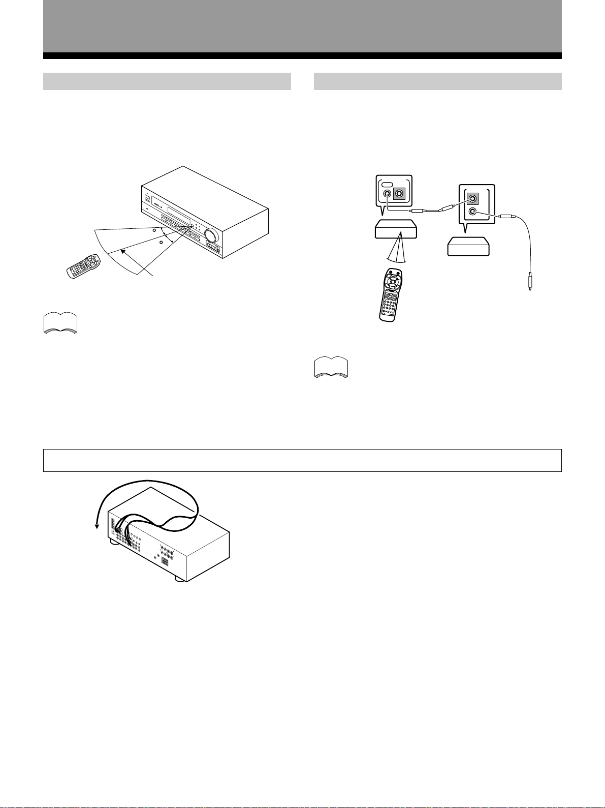
Operating range of remote control unit
Point the remote control toward the remote sensor Î on
the front panel of this unit to operate. The remote control
unit will operate the amplifier for up to a distance of 7
meters within 30° angle on each side of the sensor of the
remote sensor as illustrated below.
30
30
7m
memo
Remote control may not function properly if :
• There are obstacles between the remote
control and the remote sensor.
• Direct sunlight or fluorescent light is shining
onto the remote sensor.
• The amplifier is located near a device
emitting infrared rays.
• Operated simultaneously with another
remote control which uses infrared rays.
Operating other PIONEER components
Connecting an optional control cord allows you to
operate other PIONEER components simply by pointing
the amplifier’s remote control at the remote sensor on
the front panel of the amplifier. The amplifier then sends
the remote control signals to the other devices via the
CONTROL OUT terminal.
CONTROL
Amplifier
(VSA-E03)
memo
OUT IN
PIONEER component
bearing the Î mark.
Remote Control
You can also control PIONEER components
(and those made by other manufacturers) by
pointing the amplifier’s remote control directly
at the respective component. This type of
operation does not require control cords. All
you have to do is recall the appropriate preset
code (Refer to “Recalling preset codes” on
page 20).
CONTROL
IN
OUT
To CONTROL IN
terminal of another
PIONEER component
bearing the Î mark.
When Making Cable Connections
Be careful not to arrange cables in a manner that bends
the cables over the top of this unit as shown in the
illustration. If the cables are brought over this unit, the
magnetic field produced by the transformers in this unit
may cause a humming noise to come from the speakers.
6
En
Page 7
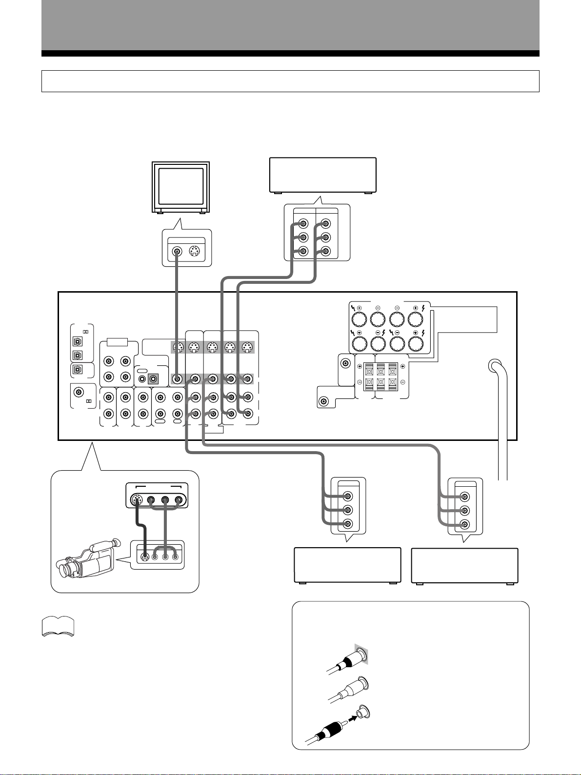
Connections
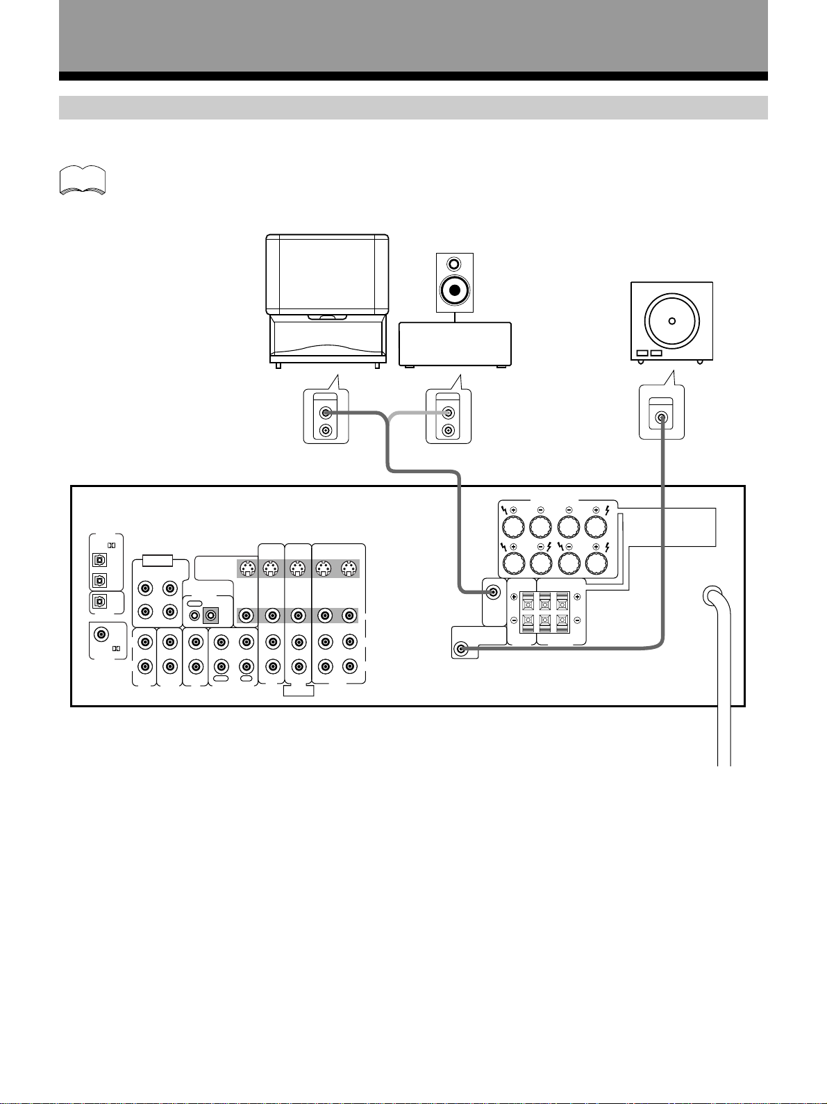
Audio Components Connections
Be sure to switch power to standby and remove the power cord from the wall outlet when you make or change
connections.
Connect your audio components as shown below. Refer to “Digital Connections” on page 9 when making digital
connections from your DVD or LD player.
SET UP OPERATION
DIGITAL
IN
PCM/
DIGITAL
DIGITAL
PCM/
OPT
DVD 5.1 CH
1
INPUT
SURROUND
L
OPT
OPT
OUT
COAX
SUBWOOFER
2
R CENTER
IN ININ
TO
MONITOR
TV
CONTROL
OUT IN
S
OUT
VIDEO
OUT
IN
L
IN
R
CD MD/TAPE
TUNERAUX
PLAY
REC
S
IN
IN IN
IN
TV/
SAT
DVD 5.1 CH
DVD/
FRONT
S
IN
INOUT
INSOUT
IN
IN OUT
S
OUT
VIDEO
L
R
LD
VCR
»»
»
Other
Component
OUTPUT
OUTPUT
L
R
L
R
Tuner
*The arrows indicate the direction of the audio signal.
OUTPUT
L
R
CD player
»
FRONT SPEAKERS
CENTER
PREOUT
SUB
WOOFER
PREOUT
CENTER
SPEAKER
SURROUND
«
PLAY
REC
LRL
R
MD recorder
or Cassette deck
L
A
B
LRR
SPEAKERS
7 Audio cords
Use audio cords (not supplied) to connect the audio
components.
L
Connect red plugs to R (right)
and white plugs to L (left).
Be sure to insert completely.
R
Cassette deck placement
Depending on where the cassette deck is placed, noise
may occur during playback of your cassette deck which
is caused by leakage flux from the transformer in the
amplifier. If you experience noise, move the cassette
deck farther away from the amplifier.
7
En
Page 8
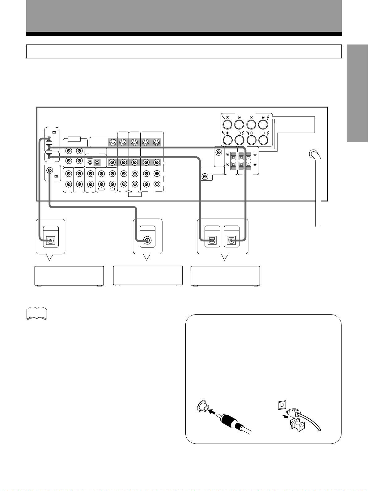
Connections
Video Components Connections
• When connecting components, the amplifier should be off and the power cord unpluged.
• Connect your video components as shown below. Also, refer to “Digital Connections” on page 9 when making digital
connections from your DVD or LD player.
• If your TV monitor or video camera has an S-Video input, clearer picture reproduction is possible by connecting the
amplifier to your TV monitor or video camera via the S-Video jack.
DIGITAL
PCM/
DIGITAL
PCM/
DIGITAL
TV
Video deck
monitor
INPUTOUTPUT
V
V
INPUT
VIDEO
S-VIDEO
»
IN
OPT
DVD 5.1 CH
1
INPUT
SURROUND
L
OPT
2
OPT
OUT
COAX
SUBWOOFER
R CENTER
IN ININ
TO
MONITOR
TV
CONTROL
OUT IN
OUT
IN IN
L
IN
R
TUNERAUX
PLAY
CD MD/TAPE
S
S
IN
IN
INOUT
DVD/
LD
DVD 5.1 CH
FRONT
INSOUT
IN
IN OUT
VCR
OUT
S
VIDEO
OUT
IN IN
TV/
REC
SAT
«
S
VIDEO
L
R
L
RL R
»
CENTER
PREOUT
SUB
WOOFER
PREOUT
CENTER
SPEAKER
FRONT SPEAKERS
LRR
SURROUND
SPEAKERS
L
A
B
7 Front
Video camera
(etc.)
memo
8
VIDEO INPUT
VIDEOS-VIDEO L AUDIO R
VIDEO INPUT
R
L
R
L
When connecting components equipped with
S-video jacks, you can make connections to
this unit using S-video cords (not supplied).
However, this unit is not designed to convert
the format of the video signal. Therefore, the
signal from the S IN cannot be output from
the VIDEO OUT and similarly the signal from
the VIDEO IN cannot be output from the S
OUT.
»
OUTPUT
V
L
R
TV tuner
(or satellite tuner)
»
DVD player
(or LD player)
OUTPUT
V
L
R
7 Audio/Video cords
Use audio/video cords (not supplied) to connect the
video components and a video cord to connect the TV
or monitor.
VIDEO
Connect red plugs to R (right),
L
white plugs to L (left), and the
yellow plugs to VIDEO.
Be sure to insert completely.
R
En
Page 9
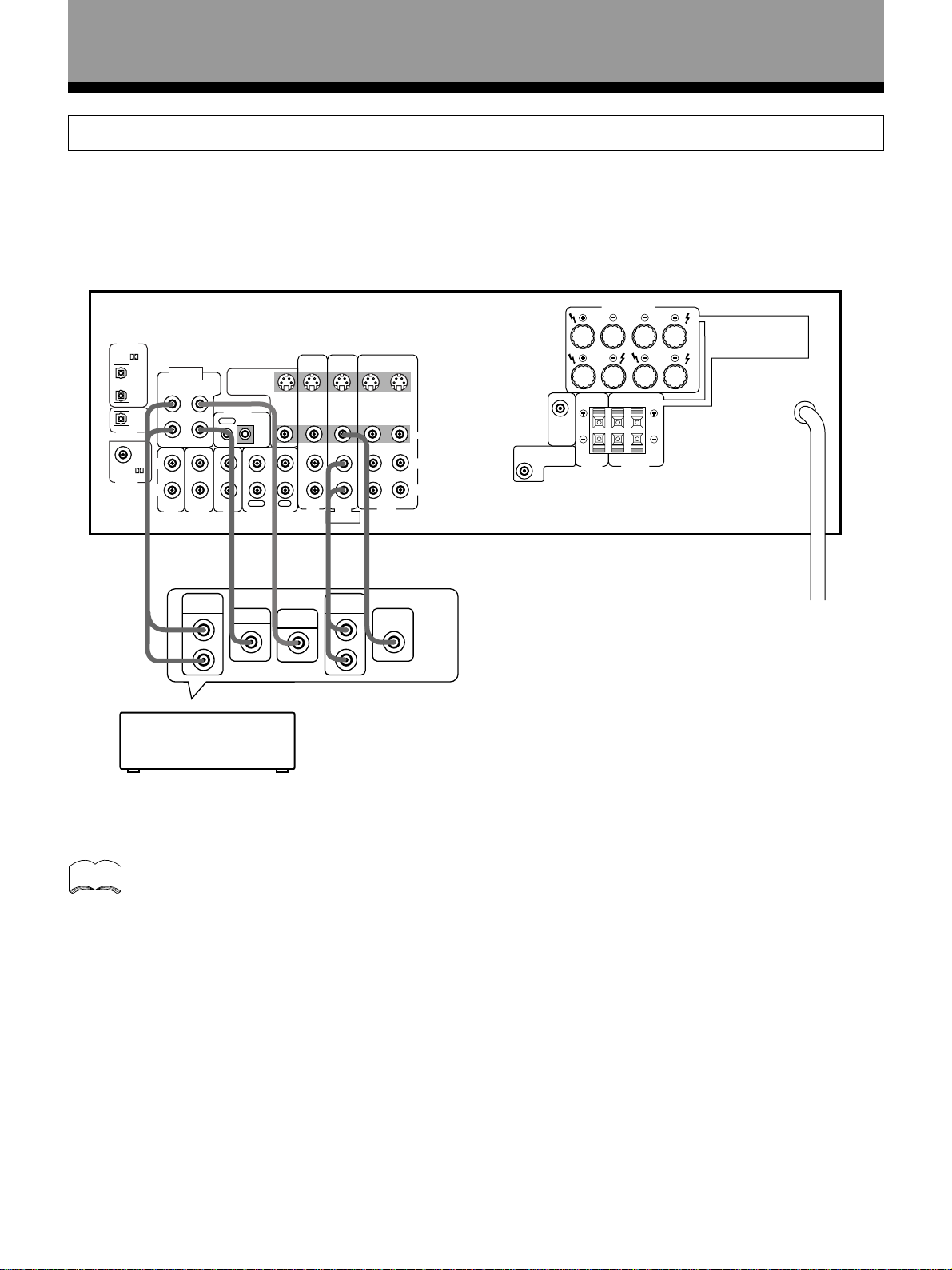
Connections
Digital Connections
Digital components can be connected as shown below. You can select up to three of the following be assigned to the
digital inputs on this unit: VCR, DVD/LD, TV/SAT, CD, MD/TAPE. To assign the digital inputs, refer to “Setting Up for
Surround Sound” on page 14.
The digital signal input is output directly to digital recording components from the optical digital output jack.
SET UP
»
DIGITAL
IN
PCM/
DIGITAL
DIGITAL
OUT
PCM/
OPT
DVD 5.1 CH
1
OPT
OPT
COAX
INPUT
SURROUND
L
2
SUBWOOFER
R CENTER
IN ININ
TO
MONITOR
TV
CONTROL
OUT IN
S
OUT
VIDEO
OUT
IN IN
L
IN
R
CD MD/TAPE
TUNERAUX
PLAY
REC
S
IN
IN IN
TV/
SAT
DVD 5.1 CH
DVD/
FRONT
S
IN
INOUT
LD
»
DIGITAL
OUT
CD player DVD player
INSOUT
IN
IN OUT
VCR
COAX
OUT
FRONT SPEAKERS
L
A
S
B
LRR
OUT
VIDEO
L
CENTER
PREOUT
SUB
WOOFER
PREOUT
CENTER
SPEAKER
SURROUND
SPEAKERS
R
»
DIGITAL
IN
DIGITAL
OUT
»
MD recorder
memo
When playing LD recorded in Dolby Digital
When connecting a DVD/LD player or LD player using
the AC-3 RF output, a commercially available RF
demodulator (RFD-1) is required. The RF demodulator
changes the RF signal to a digital signal which is then
processed by the amplifier through the digital input
jacks. For more details, refer to the instruction manual
supplied with the RFD-1.
The factory setting for each of the digital inputs is
described below.
COAX : DVD
OPT 1 : CD
OPT 2 : MD
7 Digital audio cords/Fiber-optic cables
Commercially available digital audio coaxial cords
(standard video cords can also be used) or fiber-optic
cables (not supplied) are used to connect digital
components to this amplifier.
When you use optical digital input or output terminals,
pull off the caps and insert the plugs. Be sure to insert
completely.
Digital audio cord
(or standard video cord)
Fiber-Optic cable
9
En
Page 10
Connections
DVD 5.1 Channel Connection
DVD and LD discs are often compatible with both 2 channel and 5.1 channel audio output formats. Refer to page 31 for
more information on how to switch between the two input methods.
Connections can be made from a DVD player, or Multi channel decoder equipped with 5.1 analog outputs to the 5.1
analog inputs on this unit.
DIGITAL
IN
PCM/
OPT
DVD 5.1 CH
1
DIGITAL
OUT
PCM/
DIGITAL
IN
OPT
OPT
COAX
INPUT
SURROUND
L
SUBWOOFER
2
R CENTER
IN ININ
L
R
»
TUNERAUX
SURROUND
OUTPUT
TO
MONITOR
TV
CONTROL
OUT IN
IN IN
PLAY
CD MD/TAPE
»
CENTER
L
R
Components equipped
with 5.1 channel analogue
output jacks
OUT
S
VIDEO
OUT
REC
»
SUB
WOOFER
S
IN
IN IN
TV/
SAT
DVD 5.1 CH
S
IN
INOUT
DVD/
LD
FRONT
»
FRONT
OUTPUT
INSOUT
IN
IN OUT
»
L
R
VCR
VIDEO
OUT
FRONT SPEAKERS
L
A
S
B
LRR
OUT
VIDEO
L
R
CENTER
PREOUT
SUB
WOOFER
PREOUT
CENTER
SPEAKER
SURROUND
SPEAKERS
memo
The 5.1 channel input can only be used when DVD/LD is selected.
10
En
Page 11
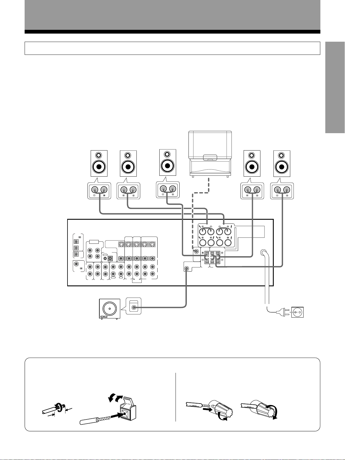
Connections
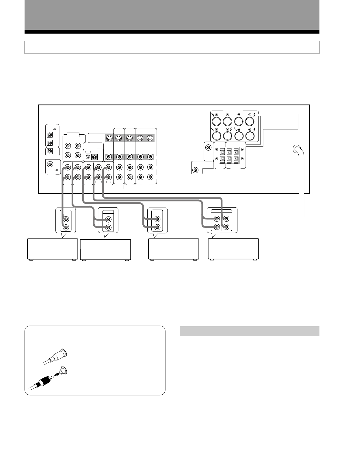
Speakers
• Use speakers with a nominal impedance of 8 Ω to 16 Ω.
• The front speaker B terminal is only used in stereo mode (Not available during DVD 5.1 channel, DSP mode, or Dolby
Surround mode).
• When you use the speaker on your TV as a center speaker, please connect the CENTER PREOUT jack on this unit to
the audio input jack on your TV. In this case, the center speaker shown below is unnecessary. Refer to the instruction
manual supplied with the TV or monitor you are connecting to for more information.
• You can set the configuration of your speaker system, whether the sizes of the speakers are large or small, and
whether or not you have a sub woofer connected. (Refer to pages 14 to 16)
• No sound is output from the front speakers if both A and B speaker systems are selected, but only one pair of
speakers is connected to the FRONT SPEAKERS terminals. To select the speaker system, refer to page 24.
SET UP
PCM/
DIGITAL
DIGITAL
PCM/
DIGITAL
Front Speakers
Center Speaker
LR
TV
(To be used as
C
the center
speaker)
Surround Speakers
L
R
(To the audio input)
FRONT SPEAKERS
L
IN
OPT
DVD 5.1 CH
1
INPUT
TO
L
SUBWOOFER
R CENTER
IN ININ
TUNERAUX
MONITOR
TV
CONTROL
OUT IN
CD MD/TAPE
SURROUND
OPT
2
OPT
OUT
COAX
L
IN
R
S
S
IN
S
OUT
VIDEO
OUT
IN IN
IN
IN
TV/
REC
PLAY
SAT
DVD 5.1 CH
FRONT
S
IN
INSOUT
IN
OUT
IN OUT
VCR
VIDEO
L
R
INOUT
DVD/
LD
CENTER
PREOUT
SUB
WOOFER
PREOUT
CENTER
SPEAKER
SURROUND
SPEAKERS
A
B
LRR
Sub Woofer
INPUT
Amplified Sub Woofer
Connection methods that differ from the example
shown in this manual may be available. For more
details, refer to the instruction manual supplied with
the sub woofer.
7 Speaker terminals
Twist exposed wire
strands together.
10 mm
Push tab to the open position, and
insert the wire. Then, close tab
firmly to secure the wire in place.
Be sure to complete all other
connections before connecting
this unit to the AC power source.
Turn counter-clockwise to loosen, and insert
the wire. Then turn clockwise to tighten.
11
En
Page 12
Connections
Connecting additional amplifiers
To use separate amplifiers to power your center speaker, make the connections shown below.
memo
Do not make simultaneous connections to both the CENTER PREOUT jack and the CENTER SPEAKER
terminals. (i.e. Do not connect a separate power amplifier to the CENTER PREOUT jack if you have already
connected a center speaker to the CENTER SPEAKER terminal.)
PIONEER
projection TV
(for center
Powered
sub woofer
channel)
Amplifier
(for center channel)
PCM/
DIGITAL
DIGITAL
DIGITAL
IN
OUT
PCM/
IN
OPT
OPT
OPT
1
2
COAX
SURROUND
L
R
DVD 5.1 CH
INPUT
L
SUBWOOFER
R CENTER
IN ININ
TUNERAUX
TO
MONITOR
OUT
TV
CONTROL
OUT IN
IN IN
PLAY
CD MD/TAPE
L-Audio
(MONO)
S
VIDEO
OUT
REC
S
IN
IN IN
TV/
SAT
DVD 5.1 CH
IN
INOUT
DVD/
LD
FRONT
AUDIO
IN
L
R
S
INSOUT
IN
IN OUT
VCR
(or)
AUDIO
IN
L
R
FRONT SPEAKERS
INPUT
L
A
S
B
LRR
OUT
VIDEO
L
R
CENTER
PREOUT
SUB
WOOFER
PREOUT
CENTER
SPEAKER
SURROUND
SPEAKERS
12
En
Be sure to complete all other
connections before connecting
this unit to the AC power source.
Page 13
Connections
Speaker placement
To achieve the best possible surround sound, install your speakers as shown below. Be sure all speakers are installed
securely to prevent accidents and improve sound quality.
Sub Woofer
SET UP
memo
Front
Left
Surround
Left
• Install the left and right front speakers at equal distances from the TV.
• When installing speakers near the TV, we recommend using magnetically shielded speakers to prevent
possible interference such as distortion in the color of the TV screen. If you do not have magnetically
shielded speakers and notice discoloration of the TV screen, place the speakers farther away from the TV.
• Install the center speaker above, below the TV so that the sound of the center channel is localized at the TV
screen.
CAUTION:
When installing the center speaker on top of the TV, be sure to secure it with tape or some other suitable
means.
Otherwise, the speaker may fall from the TV due to external shocks such as earthquakes, and it may lead to
endangering those nearby or damaging the speaker.
Center
Listening
Position
Front
Right
Surround
Right
• If possible, install the surround speakers slightly above ear level.
• It may be difficult to obtain a cohesive surround effect if the surround speakers are installed farther away
from the listening position than the front and center speakers.
13
En
Page 14
Preparations
Setting Up for Surround Sound
Be sure to switch the power of this unit on (The STANDBY indicator goes out).
To ensure the best possible surround sound, be sure to complete the following set up operations. This is particularly
important when using the
the placement of your current speaker system or add new speakers, etc.). Refer to the following pages for detailed
descriptions of the settings available for each mode.
(Dolby) Surround mode. You only need to make these settings once (unless you change
1 Press AMP to turn the power on.
The STANDBY indicator goes out.
2 Press AMP.
This switches the remote to the surround setup mode.
3 Press ! or ⁄ to select the mode you desire.
For best results, start with “SPEAKER setting mode” and make your
initial adjustments in the order described below.
The current settings are displayed automatically.
SPEAKER (Front, Center, Surround) setting mode (page 15)
Use to specify the type of speakers you have connected.
SUB WOOFER ON/OFF setting mode (page 16)
Use to specify the sub woofer as on or off.
Crossover frequency setting mode (page 16)
Use to determine which frequencies will be sent to the sub woofer or
“Large” speakers.
LFE attenuator setting mode (page 16)
Use to specify the peak level for the LFE channel and the crossover
network for rerouted bass frequencies.
Low cut filter ON/OFF setting mode (page 17)
Use to cut the distorted sound from the sub woofer.
FRONT speaker distance setting mode (page 17)
Use to specify the distance from your listening position to your front speaker.
CENTER speaker distance setting mode (page 17)
Use to specify the distance from your listening position to your center speaker.
SURROUND speaker distance setting mode (page 17)
Use to specify the distance from your listening position to your surround speakers.
Dynamic range control setting mode (page 18)
Use to compress the dynamic range of the sound track.
Coaxial digital input setting (page 18)
Use to specify the input to be assigned to the coaxial digital input.
Optical digital input 1 setting (page 18)
Use to specify the input to be assigned to the optical digital input 1.
Optical digital input 2 setting (page 18)
Use to specify the input to be assigned to the optical digital input 2.
ENTER
CHANNEL
TV/SAT
TV CONTROL
AMP
2
6
0
TV
TV FUNC
FQ
+
–
FQ
CD
TUNER
MD/TAPE
MIDNIGHT
4
3
ATT SIG.SELECT
8
7
EFFECT
MEMU
+10
TV/VCRCLASS
FL DIMMER FUNCTION DIRECT
COMMANDER
SET UP
Î
3
4
2
1
AMP
MUTING
VOL VOL
MULTI CONTROL
DVD/LD
VCR 1
VCR 2
DSP MODE
1
TEST TONE
CH.SELECT
5
CH.LEVEL
9
MODE CHECK
AUDIO/VIDEO PRE-PROGRAMMED
REMOTE CONTROL UNIT
memo
• Press ENTER to exit the setting mode.
• The setting mode is automatically exited
if no operation is performed for 20
seconds.
14
En
4 Press % or fi to select the setting you desire.
The setting is entered automatically.
5 Repeat steps 3 and 4 to set other surround modes.
Page 15
Preparations
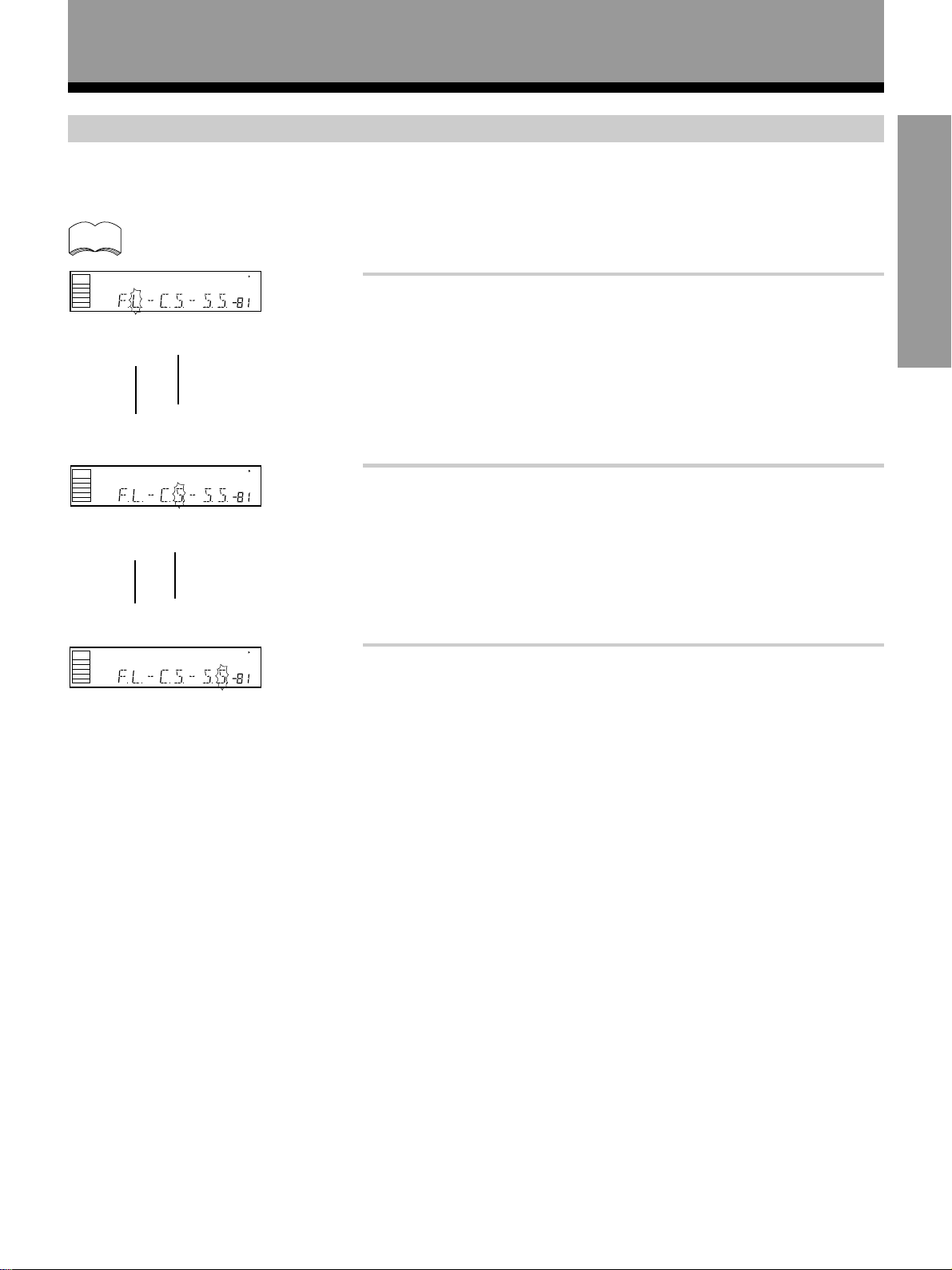
SPEAKER setting mode
Establishes the size and configuration of the speaker system you have connected.
In the display, “F”, “C”, and “S” refer to front, center, and surround speakers respectively. Speaker size is denoted as
“L” for large speakers, “S” for small speakers, and “
” (asterisk) if no speaker is connected.
∗
SET UP
memo
SIGNAL
SELECT
ANALOG
SIGNAL
SELECT
ANALOG
SIGNAL
SELECT
ANALOG
If the cone size of your speaker is larger than 12 cm, please set to Large.
A
SP
dB
2
1 Press % or fi to set the front speaker.
Front speaker (initial setting is “L (Large)”)
• Select “FL” if your speakers will reproduce bass frequencies effectively or
if you did not connect a sub woofer.
2
• Select “FS” to send bass frequencies to the sub woofer. (The center and
surround speakers cannot be set to Large if the front speakers are set to
Small. In this case, all bass frequencies are sent to the sub woofer.)
A
SP
dB
2
2 Press % or fi to set the center speaker.
Center speaker (initial setting is “L (Large)”)
• Select “CL” if your speaker will reproduce bass frequencies effectively.
• Select “CS” to send bass frequencies to the other speakers or sub woofer.
2
A
SP
dB
• Select “C
center channel is output from the front speakers.
3 Press % or fi to set the surround speaker.
” if you did not connect a center speaker. In this case, the
∗
* Press ⁄ to advance to the
next setting, and press ! to
return to previous setting.
Surround speaker (initial setting is “L (Large)”)
• Select “SL” if your speakers will reproduce bass frequencies effectively.
• Select “SS” to send bass frequencies to the other speakers or sub woofer.
• Select “S
” if you did not connect surround speakers. In this case, the
∗
sound of the surround channels is output from the front and center
speakers.
15
En
Page 16

Preparations
SUB WOOFER ON/OFF setting mode
Sets whether the SUB WOOFER is used or not.
memo
• Initial setting is “ON”.
• Setting the front speaker size to “Small” in the SPEAKER setting mode automatically locks the sub woofer
in the “ON” position.
A
ANALOG
SIGNAL
SELECT
SP
dB
Press % or fi to select sub woofer ON or OFF.
Crossover frequency setting mode
Setting speakers to “Small” in “SPEAKER setting mode” sends the respective channels’ bass frequencies to the sub
woofer (or “Large” speakers). This function lets you determine which frequencies will be sent to the sub woofer or
“Large” speakers.
memo
SIGNAL
SELECT
ANALOG
• Initial setting is “100 Hz”.
• If all speakers (front, center, and surround) are set to “Large” in SPEAKER setting mode, crossover
frequency cannot be set. (
A
SP
dB
appears in the display
∗∗∗
.)
Press % or fi to specify the crossover frequency for your small
speakers (100 Hz, 150 Hz or 200 Hz).
100 Hz
Sends bass frequencies below 100 Hz to the sub woofer (or Large
speakers).
150 Hz
Sends bass frequencies below 150 Hz to the sub woofer (or Large
speakers).
200 Hz
Sends bass frequencies below 200 Hz to the sub woofer (or Large
speakers). We recommend setting 200 Hz when only small speakers
are used.
LFE attenuator setting mode
Dolby Digital audio sources include ultra-low bass tones. Set the LFE attenuator as needed to prevent the ultra-low
bass tones from distorting the sound from the speakers.
memo
SIGNAL
SELECT
ANALOG
• Initial setting is “0 dB”.
• When ∞ is selected (
SP
∗∗
A
dB
appears in the display), LFE is not available.
Press % or fi to set the attenuation level (0 dB, 10 dB
or
dB (∞)).
∗∗
16
En
Page 17

Low cut filter ON/OFF setting mode
Turn the low cut filter ON when distorted sound is output through the sub woofer.
Preparations
memo
• Initial setting is “OFF”.
• If the SUB WOOFER is set to “OFF” in the SUB WOOFER ON/OFF setting mode, the low cut filter cannot be
set.
A
ANALOG
SIGNAL
SELECT
SP
Press % or fi to select low cut filter ON or OFF.
dB
FRONT speaker distance setting mode
Sets the distance from the FRONT speaker to the listening position.
memo
SIGNAL
SELECT
ANALOG
• Initial setting is 3 m.
• One step equals about 0.3 m.
A
SP
dB
Press % or fi to set the distance of the FRONT speaker from
the main listening position (up to 30 steps).
CENTER speaker distance setting mode
Normally as the Center speaker is placed directly in front in the listening room, it is closer to the listening position than
the Front speakers. This means that the sound from the Center speaker will be heard before the Front speakers. To
prevent this, set the Center speaker distance setting to delay the sound from the Center speaker so that the sound from
the Front and Center speakers will be heard at the same time.
SET UP
memo
• Initial setting is 3 m.
• When “C
” is selected in SPEAKER setting mode, the Center distance cannot be set.
∗
• One step equals about 0.3 m.
A
ANALOG
SIGNAL
SELECT
SP
dB
Press % or fi to set the distance of the CENTER speaker from
the main listening position (up to 30 steps).
SURROUND speaker distance setting mode
Use to set the SURROUND speaker distance. Like the CENTER speaker position, the SURROUND speakers may be set
in a location closer or farther than the FRONT speakers. Set the distance of the SURROUND speakers accurately to hear
sounds coming from both FRONT and SURROUND speakers at the same time.
memo
SIGNAL
SELECT
ANALOG
• Initial setting is 3 m.
• When “S
” is selected in SPEAKER setting mode, the SURROUND distance cannot be set.
∗
• One step equals about 0.3 m.
A
SP
dB
Press % or fi to set the distance of the SURROUND speaker
from the main listening position (up to 30 steps).
17
En
Page 18

Preparations
Dynamic range control setting mode
Dynamic range is the difference between the loudest and softest sounds in any given signal. The dynamic range control
helps you play back sounds so the quieter sounds are audible yet the louder sounds don’t get distored. It does this by
compressing the dynamic range. When watching a movie at low volume, setting this function enables low level sounds
to be heard more easily.
memo
• Initial setting is “OFF”.
• When the volume level is increased, set to OFF.
• For listening enjoyment at low volumes, set to “MAX” for maximum dynamic range compression.
• Dynamic range control is effective only when a Dolby Digital signal is being played back.
A
SIGNAL
SELECT
ANALOG
SP
dB
Press % or fi to set the dynamic range control (OFF, MAX, or
MID).
Coaxial digital input setting
Sets the input component to be assigned to the coaxial digital input jack.
memo
SIGNAL
SELECT
ANALOG
• Initial setting is “DVD”.
A
SP
dB
Press % or fi to select the coaxial digital input (DVD, TV, CD,
MD, VCR , or OFF).
Optical digital input 1 setting
Sets the input component to be assigned to the optical input 1 jack.
memo
SIGNAL
SELECT
ANALOG
• Initial setting is “CD”.
A
SP
dB
Press % or fi to select the optical digital input 1 (DVD, TV, CD,
MD, VCR , or OFF).
Optical digital input 2 setting
Sets the input to be assigned to the optical input 2 terminal.
memo
• Initial setting is “MD”.
• You cannot assign the same component to more than one digital input jack. The jack most recently
selected is established for the component and the jack formerly selected is turned off.
• DVD/LD, TV/SAT, CD, MD/TAPE, VCR digital input connection is possible.
A
SIGNAL
SELECT
ANALOG
SP
dB
Press % or fi to select the optical digital input 2 (DVD, TV, CD,
MD, VCR , or OFF).
18
En
Page 19

Preparations
Setting the volume level of each channel (Adjusting the speaker volume balance)
memo
1
4
• Sound from the SUB WOOFER seems quiet.
• The speaker volume can be adjusted without outputting the test tone by pressing CHANNEL LEVEL or
CHANNEL SELECT .
• Initial setting is 0 dB.
ENTER
CHANNEL
TV/SAT
TV CONTROL
AMP
DSP MODE
2
TEST TONE
6
0
TV
TV FUNC
FQ
+
–
FQ
CD
TUNER
MD/TAPE
MIDNIGHT
4
3
ATT SIG.SELECT
8
7
EFFECT
MEMU
+10
TV/VCRCLASS
FL DIMMER FUNCTION DIRECT
COMMANDER
SET UP
2
3,5
1 Press .
2 Press VOL + or – to adjust the volume to an appropriate
level.
3 Press TEST TONE to output the test tone.
The test tone is output in the following order.
CT FR
SL
SR
memo
FL
SW
• Depending on the “SPEAKER setting mode” chosen, some
channels may not output test tone (refer to page 15).
• Test tone is only output in Dolby Surround mode.
AMP
MUTING
VOL VOL
MULTI CONTROL
DVD/LD
VCR 1
VCR 2
1
CH.SELECT
5
CH.LEVEL
9
MODE CHECK
SET UP
AUDIO/VIDEO PRE-PROGRAMMED
REMOTE CONTROL UNIT
Î
4 Adjust speaker levels so that you hear the test tone at
the same volume from each speaker when seated in the
main listening position.
The channel level ranges +10dB~ –10dB.
memo
• Levels can be set for each surround mode.
• When both the DSP mode and Dolby Surroud mode are turned
on, priority is given to the Dolby Surround mode.
5 Press TEST TONE to turn off the test tone.
19
En
Page 20

Preparations
Setting Up the Remote Control
In addition to controlling the amplifier, the supplied remote control can operate your other components (DVD, MD, VCR,
TV, LD, CD, etc.). If your component(s) are listed in the “Preset Code List” on page 44, simply recall the corresponding
preset code. This remote control is factory set with the codes used to operate PIONEER components.
If you want to change the preset codes to operate components made by other manufacturers, follow the procedure
outlined below.
Recalling preset codes
The following steps show you how to recall preset codes for each MULTI CONTROL button. Once the preset code is
assigned, pressing the button will automatically set the remote to operate the respective component.
memo
2
1
• Refer to “Preset Code List” on page 44 for the components and manufacturers available.
• Refer to “Remote Controlling Other Components” on pages 35 to 40 and “Background Control of Other
Components” on page 41 for detailed explanations on how to operate your other components.
AMP
TV
1 Press COMMANDER SET UP and 1 at the same time to
select the preset mode.
The MULTI CONTROL buttons on the remote control start to blink.
To cancel the preset mode
Press COMMANDER SET UP.
2 Press the MULTI CONTROL button for the component you
want to control.
Each button can be set to control one of the following components
: DVD/LD player
DVD/LD
TV/SAT
: TV or Satellite tuner
CD
: CD player
TUNER
: Tuner
MD/TAPE
: MD recorder or Tape recorder
VCR 1
: Video deck
: Video deck
VCR 2
TV CONTROL
: TV or Cable TV tuner
MUTING
DVD/LD
VCR 1
VCR 2
CH.SELECT
MODE CHECK
AUDIO/VIDEO PRE-PROGRAMMED
FQ
+
ENTER
–
FQ
VOL VOL
CHANNEL
MULTI CONTROL
TV/SAT
TV CONTROL
AMP
DSP MODE
1
2
3
ATT SIG.SELECT
TEST TONE
6
5
7
CH.LEVEL
9
0
+10
REMOTE CONTROL UNIT
TV FUNC
CD
TUNER
MD/TAPE
MIDNIGHT
4
8
EFFECT
MEMU
TV/VCRCLASS
FL DIMMER FUNCTION DIRECT
COMMANDER
SET UP
Î
3
20
En
3 Point the remote control toward the component to be
controlled, enter the 3 digit setup code.
When a three digit code number is input, a power ON/OFF signal is
output from the remote control unit. If the power of the device turns
ON or OFF corresponding to this signal, it indicates that the device has
been set properly. If the power does not turn ON/OFF, input another
code.
Repeat steps 2 through 3 to assign preset codes for as many
components as necessary.
Page 21

Preparations
DSP MODE
CH.SELECT
ATT SIG.SELECT
MIDNIGHT
TEST TONE
AUDIO/VIDEO PRE-PROGRAMMED
REMOTE CONTROL UNIT
2
3
5
0
6
9
+10
TV/VCRCLASS
7
8
4
1
CN.LEVEL
EFFECT
FL DIMMER FUNCTION DIRECT
MODE CHECK
COMMANDER
SET UP
Î
MEMU
4 Press COMMANDER SET UP to exit the preset mode.
The remote control returns to the previous operation mode.
memo
• When operating a PIONEER’S DVD/LD player, set the
manufacturer code to “000” in the preset mode.
• AMP button cannot be preset.
Clearing the Remote Control Settings
Clears all presets and restores factory installed presets.
0
COMMANDER
SET UP
Press COMMANDER SET UP and 0 at the same time for more
3 seconds.
• All the multi-control buttons on the remote control blinks. After
blinking three times, all the settings are canceled.
SET UP
21
En
Page 22

Names of Parts and Basic Operations
Display
123456
SIGNAL
SELECT
ANALOG
DIGITAL
AC-3
PRO LOGIC
DIGITAL
LCR
LFE
-
=
SFC
ATT MIDNIGHT LOUDNESS
RSSLS
7
~
8
DIRECT
H.P
0
9
AB
SP
dB
!
1 SIGNAL SELECT indicators
Light to indicate the type of input signal selected for
the current component (refer to “Front Panel”, =,
SIGNAL SELECT on page 24).
ANALOG : Lights when the analog audio signals are selected.
DIGITAL : Lights when the digital audio signals are selected.
AC-3 : Lights when a source with Dolby Digital signals is played.
2 Digital indicators
PRO LOGIC :
the amplifier is on,
channel playback of Dolby Digital sources.
DIGITAL :
amplifier is on, this indicator lights to indicate
playback of a Dolby Digital signal. However, PRO
LOGIC lights during 2 channel playback of Dolby
Digital.
When the Dolby Surround mode on
this indicator lights during 2
When the Dolby Surround mode on the
3 SFC (DSP) mode indicator
Lights when the DSP mode is selected (refer to on
page 26).
4 ATT indicator
Lights when ATT (refer to “Remote Control”, 7,
Number buttons on page 23) is used to reduce the
level of the input signal (available in ANALOG mode only).
5 Overload indicator
When “ANALOG” is selected in SIGNAL SELECT, this
indicator lights to show that an excessively strong
signal is being processed. When this occurs, press
ATT on the remote control to attenuate the signal
(refer to “Remote Control”, 7, Number button on
page 23).
6 MIDNIGHT indicator
Lights when the MIDNIGHT mode is on.
(refer to “Front Panel”,! , MIDNIGHT on page 25).
7 LOUDNESS indicator
Lights when loudness is on. (refer to “Front Panel”,
9, LOUDNESS on page 24).
8 DIRECT indicator
Lights when direct playback is on (refer to “Front
Panel”, ^, DIRECT on page 25).
9 H.P indicator
Lights when headphones are plugged in.
0 Speaker indicators
Light to indicate the current speaker system (refer to
“Front Panel”, 5, SPEAKERS (A/B) on page 24).
SP 3 A : Lights when speaker system A is selected.
SP 3 B : Lights when speaker system B is selected.
- Program format indicators
The following indicators light to show the channels
being played back.
L : Left front*
LS : Left surround*1, S : Surround (mono)*2,
RS : Right surround*
1*2
, C : Center*1, R : Right front*1*2,
1
*1: Indicates 5.1ch Dolby Digital playback.
*2: Indicates Dolby Pro Logic playback.
= LFE indicator
LFE (Low Frequency Effects) indicator lights to
indicate that the program source contains an LFE
channel. The indicator to the left of LFE lights during
actual playback of the LFE signals (LFE signals are not
present in all parts of the sound track).
~ Character display
! Volume level display
Displays the volume level. Volume level is maintained
even when the power is off. ---dB indicates the
minimum level, and 0dB indicates the maximum
level.
• Depending on the level settings for individual
channels, the MAX level can range between –10dB
and 0dB.
22
En
Page 23

Remote Control
Names of Parts and Basic Operations
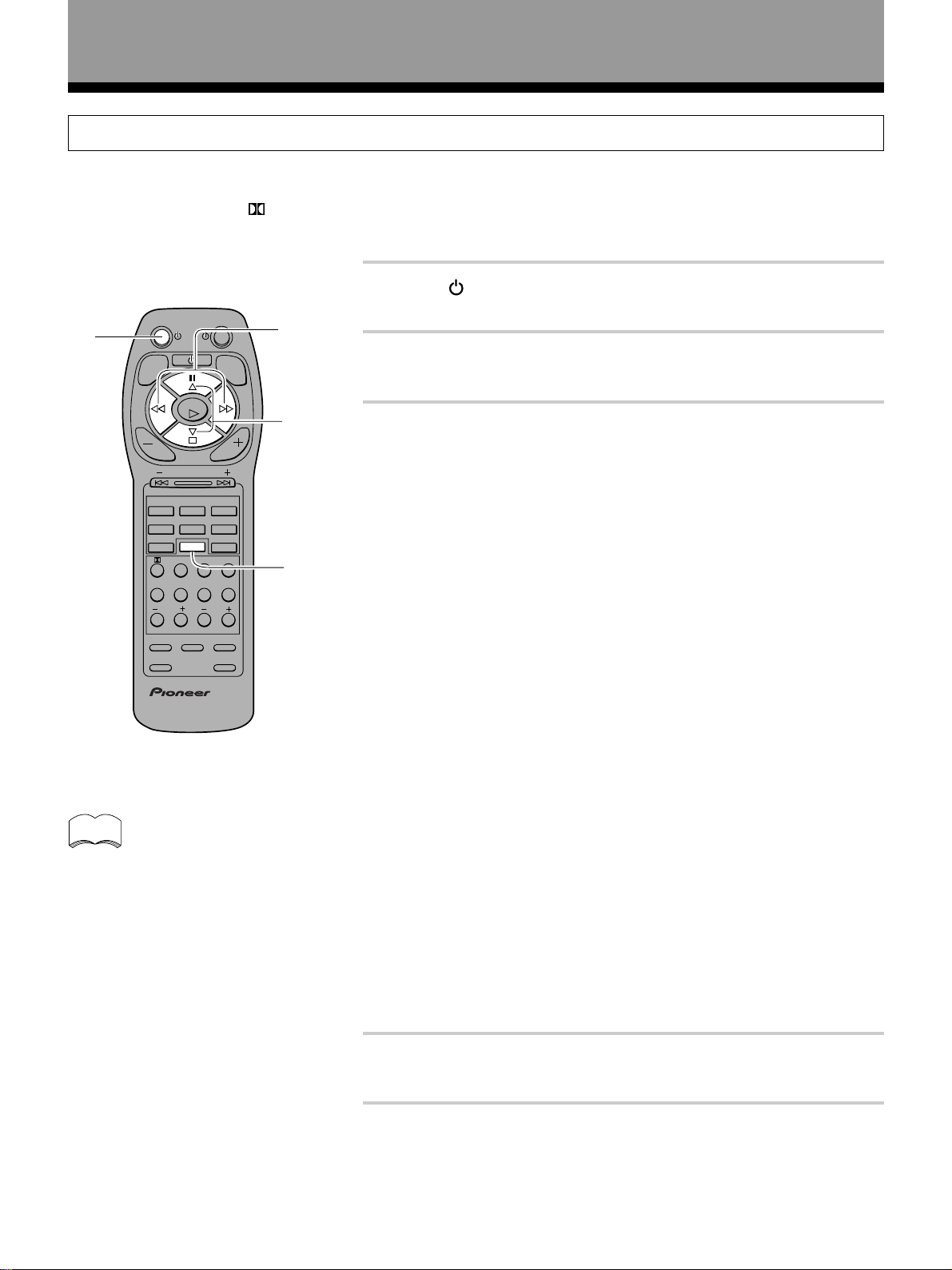
These pages describe the buttons on the remote control
used to operate the amplifier.
0
AMP
TV
1
ENTER
CHANNEL
TV/SAT
TV CONTROL
AMP
DSP MODE
2
6
0
TV FUNC
FQ
+
–
FQ
CD
TUNER
MD/TAPE
MIDNIGHT
4
3
ATT SIG.SELECT
8
7
EFFECT
MEMU
+10
TV/VCRCLASS
FL DIMMER FUNCTION DIRECT
COMMANDER
SET UP
Î
-
=
~
!
@
2
3
4
5
6
7
8
9
MUTING
VOL VOL
MULTI CONTROL
DVD/LD
VCR 1
VCR 2
1
CH.SELECT
TEST TONE
5
CH.LEVEL
9
MODE CHECK
AUDIO/VIDEO PRE-PROGRAMMED
REMOTE CONTROL UNIT
1 AMP button
Press to switch the amplifier on or to put in standby.
2 MUTING button
Press to mute the volume. “MUTING” appears in the
display. Press again to cancel.
3 [When set to SURROUND]
@, #,%, fi, (Select/Adjust) buttons
[When set to other than OPERATIONS]
*(Pause), &(Stop), !(Rewind), ⁄(Fast Forward),
ENTER/‹(Play) buttons
[Tuner Operations]
FQ + (to higher frequencies), FQ – (to lower
frequencies), !(MPX), ⁄(DISP MODE), # (FM/AM)
buttons
!(MPX): Use to switch the auto stereo/monaural
mode for receiving FM broadcasts. When the
received broadcast signal is weak, press this button
to set the monaural mode.
⁄(DISP MODE): Use to switch the RDS data while
listening to an FM station. Each press changes the
display in the order of RT, PS, PTY, and frequency.
4 VOL (–/+) buttons
Press to adjust the volume. When VOL (–/+) buttons
are pressed while muting, muting is canceled.
5 CHANNEL (–/+) button
Use to select preset stations when operating the
tuner. When the remote is used to control other
components, this button may be used to change
channels, tracks, or chapters.
6 MULTI CONTROL buttons
Use these buttons to select the remote operation
mode.
For example, pressing TUNER sets the remote to
operate the tuner functions.
7 Number buttons
These buttons can perform a variety of different
functions depending on the remote operation mode.
• [AMPLIFIER operations (press AMP first)]
: Switches the Dolby Surround mode on or
off(refer to page 29).
DSP MODE : Press repeatedly to select a DSP sound
mode (refer to page 26, 30).
MIDNIGHT : Press to hear surround sound effectively
at low volumes (refer to page 31).
CH.SELECT : Use to select a speaker when adjusting
speaker levels.
TEST TONE : Press to switch the test tone on or off
when listening to a surround mode (refer to page 19).
ATT : Press to attenuate (lower) the level of the input
signals and prevent distortion (refer to “Display”, 5,
Overload indicator on page 22).
SIG.SELECT : When the same component uses both
analog and digital connections, use to select input
signals as digital or analog.
CH.LEVEL (–/+) : Use to adjust individual speaker
levels after having pressed CH. SELECT to select a
speaker channel.
EFFECT (–/+) : Use to adjust the DSP mode effect level.
8 FUNCTION button
Press repeatedly to select a source.
9 MODE CHECK button
Press to confirm the current remote operation mode
and to switch operation modes without changing the
source (refer to page 41).
0 Power button
Press to turn on or put in standby all connected
components other than this unit.
- TV, TV FUNC button
Press TV to turn the TV’s power on or put in standby.
Press TV FUNC to select the TV for remote control
operation.
= AMP button
Press to select the amplifier for remote control
operation.
~ FL DIMMER button
Press to adjust the brightness of the fluorescent
display. Four levels of brightness ranging from very
dim to very bright can be selected.
! COMMANDER SET UP button
Use to customize the remote control functions.
(Refer to “Setting Up the Remote Control” starting on
page 20).
@ DIRECT button
Use to playback original source audio. When DIRECT
is ON, Dolby Surround, DSP, LOUDNESS, and
MIDNIGHT mode are automatically turned OFF.
SET UP
OPERATION
23
En
Page 24

Names of Parts and Basic Operations
Front Panel
5
1
2
STANDBY/ON
–
OFF
3
STANDBY
PHONES
#
AUDIO/VIDEO MULTI-CHANNEL AMPLIFIER
CHANNEL
LEVEL
–
-
ON
$
4
N∫z¿x?≤
CHANNEL
SELECT
+
SPEAKERS
A B
VCR DVD/LD VIDEOTV/SAT TUNERCDMD/TAPE AUX
–
DVD 5.1CH
1 Main power switch (— OFF, _ ON)
STANDBY/ON button
2
Press to switch the amplifier on or put in standby.
3 STANDBY indicator
Lights when the amplifier is in standby mode. (Please
note that this amplifier consumes a small amount of
power (2 W) during the standby mode.)
4 CHANNEL SELECT button
Use to select a speaker when ajusting speaker levels.
5 SPEAKERS (A/B) buttons
Use to switch the corresponding speaker system on
or off. To listen to both speaker systems (A and B),
press the buttons so that both A and B appear in the
display (refer to “Display”, 0, Speaker indicators on
page 22). Only A speakers are available when using
surround sound modes.
6 BASS (–/+) button
Press to adjust low frequencies in the range of ±6.
7 Display (Refer to page 22)
8 TREBLE (–/+) button
Used to adjust high frequencies in the range of ±6.
9 LOUDNESS button
Switches the loudness on or off. Use to raise the level
of the bass and treble so they can be more easily
heard when listening at low volumes.
0 Remote sensor
Point the remote control toward the remote sensor to
operate the amplifier.
24
7
6
BASS TREBLE
–
+
%
8
9
+
LOUDNESS
0
-=
SIGNAL
SELECT
DIRECT
MIDNIGHT
~
DSP
MODE
!
^
@
DOWN UP
VIDEO INPUT
L
AUDIO
VIDEO
S-VIDEO
&
MASTER
VOLUME
R
- (Dolby) Surround button
Press to select the (Dolby) Surround mode. This
mode automatically switches between Dolby Digital
and Dolby Pro Logic decoding according to the input
signal. (Refer to page 29 for more information about
Dolby Digital.)
= SIGNAL SELECT button
Use to select input signals for the digital components.
First press VCR, DVD/LD, TV/SAT, CD or MD/TAPE (%,
Function buttons) to select the component, then press
SIGNAL SELECT repeatedly to select one of the
following:
ANALOG : Selects the analog (R and L) audio signals.
DIGITAL : Selects the digital audio signals. This
amplifier automatically detects and displays the
format of the signal being input. AC-3 lights when
Dolby Digital signals are input. (AC-3 decoding is
switched automatically.)
• SIGNAL SELECT is fixed in the “ANALOG” position
for components not assigned to one of the three
digital input jacks.
• Because the audio from a karaoke microphone and
LD recorded with analog audio only is not output
from the digital output, set SIGNAL SELECT to
“ANALOG”.
• This amplifier can only play back Dolby Digital,
PCM (32kHz, 44kHz, and 48kHz) signal formats. With
digital signal formats other than these, set SIGNAL
SELECT to “ANALOG”.
~ DSP MODE button
Press repeatedly to select a DSP sound mode (HALL 1,
HALL 2, JAZZ, DANCE, THEATER 1, or THEATER 2).
Use these modes to produce surround sound from
standard (two channel) stereo sources (refer to page
26, 30).
En
Page 25

! MIDNIGHT button
Press to hear effective surround sound at low volume
levels. The effect is automatically adjusted according
to the volume level.
@ MASTER VOLUME
After turning on the desired component, rotate to
adjust the volume.
# PHONES jack
Connect headphones for private listening (the
speakers turn off automatically).
$ CHANNEL LEVEL (–/+) button
Use to adjust individual speaker levels after having
pressed CHANNEL SELECT to select a speaker
channel.
% Function buttons
Selects the function. Each press switches the DVD/LD
input between DVD/LD and DVD 5.1 channel.
^ DIRECT button
Switches direct playback on or off. Use to bypass the
amplifier’s tone control circuitry or level control for
higher fidelity to the program source. When DIRECT
is ON, Dolby Surround, DSP, LOUDNESS, and
MIDNIGHT mode are automatically turned OFF.
& VIDEO INPUT jacks
Connect a video camera, video game system, etc. to
the VIDEO INPUT jacks (refer to page 8).
Names of Parts and Basic Operations
SET UP
OPERATION
25
En
Page 26

Sound Modes
This amplifier incorporates two surround modes for enjoyment of a variety of program sources.
Surround modes
(Dolby) Surround mode
Use this mode when playing Dolby Digital or Dolby Surround software. Decoding switches automatically according to
the input signal, so all you have to do is enjoy!
You can identify Dolby Digital software by the
DOLBY SURROUND
For more information about Dolby formats, refer to page 42.
, but unmarked software may also incorporate Dolby Pro Logic.
DSP modes
The DSP (Digital Signal Processing) modes allow you to transform your living room into a variety of different sonic
environments when playing standard (two-channel) stereo sources, Dolby Surround sources, and Dolby Digital sources.
HALL 1
Simulates the acoustic environment of a large concert hall of wooden construction. Complex delay of reflected
sounds coupled with reverberation effects create a dynamic and beautiful sound characteristic of an orchestra
performing in a concert hall, making it suitable for classical music
HALL 2
Simulates the acoustic environment of a concert hall with stone walls. The rich reverberations and natural fullness
of the sound create the auditory impression of being in a concert hall, making it suitable for classical music.
JAZZ
Simulates the acoustic environment of a jazz club. Less delay on the reflected sounds emphasizes the sensation of
hearing a live band.
DOLBY
DIGITAL
AC-3 DIGITAL
or
marks. Most Dolby Surround software is marked
DANCE
Simulates the acoustic environment and strong bass sound of a nightclub with a square dance floor. A short delay
on the reflected sounds emulates the raw power of the dance music.
THEATER 1
Adjusts the delay of the reflected sound to simulate the acoustic environment of a medium sized movie theater.
THEATER 2
Simulates the acoustic environment of a theater while maintaining proper localization of each channel.
26
En
Page 27

Sound Modes
Switching ANALOG/DIGITAL Signal Input
The input of the component set in the digital input setting (Refer to page 18) can be switched to an analog or digital
input signal by pressing the SIGNAL SELECT button.
AMP
MUTING
DVD/LD
VCR 2
CH.SELECT
MODE CHECK
AUDIO/VIDEO PRE-PROGRAMMED
FQ
+
ENTER
FQ
VOL VOL
CHANNEL
MULTI CONTROL
TV/SAT
TV CONTROL
VCR 1
AMP
DSP MODE
1
2
3
ATT SIG.SELECT
TEST TONE
6
5
7
CH.LEVEL
9
0
+10
REMOTE CONTROL UNIT
TV
TV FUNC
–
CD
TUNER
MD/TAPE
MIDNIGHT
4
8
EFFECT
MEMU
TV/VCRCLASS
FL DIMMER FUNCTION DIRECT
COMMANDER
SET UP
Î
1
2
1 Press AMP.
This sets the remote to select the sound mode.
(You can skip this step when using the controls on the amplifier.)
2 Press SIG. SELECT on the remote control or SIGNAL
SELECT on the front panel to select the input signal
corresponding to the source component.
Each press switches between ANALOG and DIGITAL signal selection.
SIGNAL
SELECT
ANALOG
SIGNAL
SELECT
DIGITAL
3
While SIGNAL SELECT is set to DIGITAL, AC-3 lights when a Dolby
SIGNAL
SELECT
ANALOG
SIGNAL
SELECT
DIGITAL
Digital signal is input.
A
SP
A
SP
OPERATION
2
SIGNAL
SELECT
DIGITAL
AC-3
SIGNAL
SELECT
DIGITAL
AC-3
A
SP
When a Dolby Digital signal is input.
memo
• SIGNAL SELECT is fixed in the “ANALOG” position for components not
assigned to one of the three digital input jacks.
• Because the audio from a karaoke microphone and LD recorded with
analog audio only is not output from the digital output, set SIGNAL
SELECT to “ANALOG”.
• This amplifier can only playback Dolby Digital, PCM (32kHz, 44kHz, and
48kHz) signal formats. With digital signal formats other than these, set
SIGNAL SELECT to “ANALOG”.
27
En
Page 28

Sound Modes
Playback
2
6
3
AMP
MUTING
DVD/LD
CH.SELECT
MODE CHECK
AUDIO/VIDEO PRE-PROGRAMMED
FQ
+
ENTER
–
FQ
VOL VOL
CHANNEL
MULTI CONTROL
TV/SAT
TV CONTROL
VCR 1
AMP
VCR 2
DSP MODE
1
2
3
ATT SIG.SELECT
TEST TONE
6
5
7
CH.LEVEL
9
0
+10
REMOTE CONTROL UNIT
TV
TV FUNC
CD
TUNER
MD/TAPE
MIDNIGHT
4
8
EFFECT
MEMU
TV/VCRCLASS
FL DIMMER FUNCTION DIRECT
COMMANDER
SET UP
Î
4
1 Turn on the power of the playback component.
2 Press AMP to turn on the amplifier.
Be sure that the standby indicator turns off on
the front panel.
STANDBY
indicator
3 Press FUNCTION to select the source you want to
playback.
The source you want to playback is displayed in the following order:
TUNER MD/TAPE AUX VCR
VIDEO
TV/SAT
DVD/LDCD
4 Press SIG. SELECT on the remote control or SIGNAL
SELECT on the front panel to select the input signal
corresponding to the source component.
(Refer to “Switching ANALOG/DIGITAL signal input” on page 27.)
2
28
En
3
4
6
5 Start playback of the component you selected in step 1.
6 Press VOL (–/+) to adjust the volume level in the range of
--- dB (MIN) to 0 dB (MAX).
memo
• Depending on the channel level setting, the MAX volume level
may differ 0 to –10 dB from the level displayed.
• When this amplifier is not going to be used for a long time, it is
recommended that you turn off the main power.
Page 29

Playing Sources with Dolby Digital
Sound Modes
6
4
3
1
1
2
AMP
MUTING
DVD/LD
VCR 1
VCR 2
CH.SELECT
MODE CHECK
AUDIO/VIDEO PRE-PROGRAMMED
FQ
ENTER
FQ
VOL VOL
CHANNEL
MULTI CONTROL
TV/SAT
TV CONTROL
AMP
DSP MODE
1
2
3
ATT SIG.SELECT
TEST TONE
6
5
7
CH.LEVEL
9
0
+10
REMOTE CONTROL UNIT
TV
TV FUNC
+
–
CD
TUNER
MD/TAPE
MIDNIGHT
4
8
EFFECT
MEMU
TV/VCRCLASS
FL DIMMER FUNCTION DIRECT
COMMANDER
SET UP
Î
1 Follow steps 1 to 3 of the playback procedure. (Refer to
“Playback” on page 28.)
1 Turn on the power of the playback component.
2 Press
3 Press FUNCTION to select the source component you want to
play.
AMP to turn on the amplifier.
2 Press AMP.
This sets the remote to select the sound mode.
(You can skip this step when using the controls on the amplifier.)
3 Press SIG.SELECT on the remote control or SIGNAL
SELECT on the front panel to select DIGITAL.
(Refer to “Switching ANALOG/DIGITAL signal input” on page 27.)
4 Press to switch the Dolby Surround mode on.
Each press changes the Dolby Surround mode.
OPERATION
5 Start playback of the component you selected in step 1.
6 Press VOL (–/+) to adjust the volume level.
1
memo
When playing LD recorded in Dolby Digital
When connecting a DVD/LD player or LD player using the AC-3 RF output, a commercially available RF demodulator
(RFD-1) is required. The RF demodulator changes the RF signal to a digital signal which is then processed by the
amplifier at the digital input jacks. For more details, refer to the instruction manual supplied with the RFD-1.
Refer to pages 42 for explanations of Dolby Digital, Dolby Pro Logic.
4
3
6
29
En
Page 30

Sound Modes
Selecting a Sound Mode
To ensure the best possible surround sound, be sure to complete the set up procedures described in “Setting Up for
Surround Sound” (starting on page 14) before using the sound modes. This is particularly important when using the
(Dolby) Surround mode. When using the sound modes, SPEAKERS A are used. If SPEAKERS B are selected and a
sound mode is turned on, selection automatically switches to SPEAKERS A only.
Surrround operation
2
AMP
MUTING
DVD/LD
VCR 2
CH.SELECT
MODE CHECK
AUDIO/VIDEO PRE-PROGRAMMED
FQ
+
ENTER
–
FQ
VOL VOL
CHANNEL
MULTI CONTROL
TV/SAT
TV CONTROL
VCR 1
AMP
DSP MODE
1
2
3
ATT SIG.SELECT
TEST TONE
6
5
7
CH.LEVEL
9
0
+10
REMOTE CONTROL UNIT
TV
TV FUNC
CD
TUNER
MD/TAPE
MIDNIGHT
4
8
EFFECT
MEMU
TV/VCRCLASS
FL DIMMER FUNCTION DIRECT
COMMANDER
SET UP
Î
1
EFFECT –/+
1 Press AMP.
This sets the remote to select the sound mode.
(You can skip this step when using the controls on the amplifier.)
2 Press DSP MODE to select the sound mode.
Each press changes the DSP mode as follows:
=HALL 1 = HALL 2 = JAZZ = DANCE
SFC OFF+ THEATER 2 + THEATER 1 +
memo
• The amount of effect of each DSP mode can be adjusted in the range of 10
to 90 (the default setting value is 70) by pressing EFFECT –/+.
30
En
2
Page 31

dB
SP
SIGNAL
SELECT
ANALOG
A
Sound Modes
DVD 5.1ch input playback
Connect a component with 5.1 channel output to enjoy the surround sound created by 5.1 channel playback.
Press DVD/LD on the unit.
DVD/LD
Each press switches the input: DVD/LD j DVD 5.1ch
A
SIGNAL
SELECT
ANALOG
DIGITAL
DIGITAL
AC-3
LCR
RSLS
LEF
SP
j
dB
memo
• When DVD 5.1ch input is selected, Dolby Surround mode, DSP
mode, SIGNAL SELECT, ATT, DIRECT, TONE, MIDNIGHT mode,
and speakers B cannot be operated.
• When DVD 5.1ch input is selected, only the volume level ,
channel levels and LOUDNESS can be set.
Listening in MIDNIGHT Listening Mode
When the volume is low, surround effects tend to become less than satisfactory. Turn the MIDNIGHT listening mode on
to enjoy the effects of quality surround sound even at low volumes. This mode allows you to hear effective surround
sound of movies at low volume levels.
ENTER
CHANNEL
TV/SAT
TV CONTROL
AMP
DSP MODE
2
TEST TONE
6
0
TV
TV FUNC
FQ
+
–
FQ
CD
TUNER
MD/TAPE
MIDNIGHT
4
3
ATT SIG.SELECT
8
7
EFFECT
MEMU
+10
TV/VCRCLASS
FL DIMMER FUNCTION DIRECT
COMMANDER
SET UP
Î
1
2
1 Press AMP.
This sets the remote to select the sound mode.
(You can skip this step when using the controls on the amplifier.)
2 Press MIDNIGHT.
Each press switches MIDNIGHT listening mode on or off.
A
SIGNAL
SELECT
ANALOG
DIGITAL
AC-3
DIGITAL
LCR
LEF
RSLS
MIDNIGHT
memo
The effect automatically adjusts according to the volume level.
SP
dB
AMP
MUTING
VOL VOL
MULTI CONTROL
DVD/LD
VCR 1
VCR 2
1
CH.SELECT
5
CH.LEVEL
9
MODE CHECK
AUDIO/VIDEO PRE-PROGRAMMED
REMOTE CONTROL UNIT
OPERATION
2
31
En
Page 32

Sound Modes
Adjusting bass and treble (tone control)
Use BASS (–/+) or TREBLE (–/+) to adjust the low and high frequencies.
TREBLE –/+
Press BASS (–/+) to adjust the low frequencies.
SIGNAL
SELECT
ANALOG
Press TREBLE (–/+) to adjust the high frequencies.
SIGNAL
SELECT
ANALOG
BASS –/+
memo
• The tone control can be adjusted in a range of ±6.
• Pressing + and – simultaneously restores the setting to 0.
• In cases described below, the tone control cannot be adjusted.
1 Dolby Surround mode is ON.
2 DSP mode is ON.
3 DVD 5.1ch input is selected.
4 Dolby Digital signals are being input.
Adjusting the brightness of the display
A
SP
dB
A
SP
dB
Use FL DIMMER to adjust the brightness of the fluorescent display.
ENTER
CHANNEL
TV/SAT
TV CONTROL
2
6
0
TV
TV FUNC
FQ
+
–
FQ
TUNER
AMP
MD/TAPE
MIDNIGHT
3
ATT SIG.SELECT
7
EFFECT
+10
FL DIMMER FUNCTION DIRECT
COMMANDER
SET UP
CD
4
8
MEMU
TV/VCRCLASS
Î
FL DIMMER
Press FL DIMMER.
Four levels of brightness ranging from very dim to very bright can be
selected. Each press changes the brightness of the display. When rotating
through the options, the default brightness can also be selected.
memo
In standby, pressing
Surround button (both on the front panel) returns the display to the default
brightness.
AMP
MUTING
VOL VOL
MULTI CONTROL
DVD/LD
VCR 1
VCR 2
DSP MODE
1
TEST TONE
CH.SELECT
5
CH.LEVEL
9
MODE CHECK
AUDIO/VIDEO PRE-PROGRAMMED
REMOTE CONTROL UNIT
STANDBY/ON while holding down (Dolby)
32
En
Page 33

Other Operations
Recording from Audio Components
The following operations show you how to record audio to the cassette, DAT, or MD deck connected to the MD/TAPE
jacks.
memo
2
The amplifier’s volume, tone (BASS, TREBLE, MIDNIGHT and LOUDNESS), and surround effects have no
effect on the recorded signal.
AMP
TV
1 Prepare the program source.
(Tune in the radio station or load the CD, etc.)
TV FUNC
MUTING
DVD/LD
CH.SELECT
MODE CHECK
AUDIO/VIDEO PRE-PROGRAMMED
FQ
+
ENTER
–
FQ
VOL VOL
CHANNEL
MULTI CONTROL
VCR 1
VCR 2
DSP MODE
1
TEST TONE
5
CH.LEVEL
9
REMOTE CONTROL UNIT
TV/SAT
TV CONTROL
AMP
2
6
0
CD
TUNER
MD/TAPE
MIDNIGHT
3
ATT SIG.SELECT
7
EFFECT
MEMU
+10
TV/VCRCLASS
FL DIMMER FUNCTION DIRECT
COMMANDER
SET UP
2 Select the component you want to record.
Press SIG. SELECT on the remote or SIGNAL SELECT on the front
panel to select “ANALOG” when making analog recordings, or
“DIGITAL” when making digital recordings. (Refer to “Switching
ANALOG/DIGITAL signal input” on page 27.)
3 Insert a blank tape into the cassette deck (MD/TAPE) and
adjust the recording level (if necessary).
4
8
Î
SIG. SELECT
4 Start recording on the cassette deck, then start playback
from the source component.
memo
• This amplifier outputs the input signal directly to the recording
device. As there is no conversion of the audio signal,
recordings cannot be made from analog to digital, and similarly
SIGNAL SELECT
from digital to analog.
• Recording cannot be made from MD/TAPE.
OPERATION
2
33
En
Page 34

Other Operations
Recording from Video Components
The following operations show you how to record audio and video to the video tape recorder connected to the VCR
jacks.
memo
2
The amplifier’s volume, tone (BASS, TREBLE, MIDNIGHT and LOUDNESS), and surround effects have no
effect on the recorded signal.
AMP
TV
1 Prepare the program source.
(Load the DVD or LD, etc.)
TV FUNC
MUTING
VOL VOL
DVD/LD
VCR 1
VCR 2
1
CH.SELECT
5
9
MODE CHECK
AUDIO/VIDEO PRE-PROGRAMMED
ENTER
CHANNEL
MULTI CONTROL
TV/SAT
TV CONTROL
AMP
DSP MODE
2
TEST TONE
6
CH.LEVEL
0
REMOTE CONTROL UNIT
FQ
+
–
FQ
CD
TUNER
MD/TAPE
MIDNIGHT
4
3
ATT SIG.SELECT
8
7
EFFECT
MEMU
+10
TV/VCRCLASS
FL DIMMER FUNCTION DIRECT
COMMANDER
SET UP
Î
SIG. SELECT
2 Select the component you want to record.
Be sure to press SIG. SELECT on the remote or SIGNAL SELECT on the
front panel to choose “ANALOG”. (Refer to “Switching ANALOG/
DIGITAL signal input” on page 27.)
3 Insert a blank tape into the video tape recorder VCR.
4 Start recording on the video tape recorder, then start
playback from the source component.
memo
• Recording cannot be made from analog to digital, and similarly
from digital to analog.
• When recording a DVD, the recorded image may flicker or be
difficult to view because of the copy protection signal
programmed on the DVD.
SIGNAL SELECT
34
En
2
Page 35

Remote Controlling Other Components
DVD or LD player operations
Other Operations
memo
1
2
3
4
5
Before attempting to perform these operations, press the DVD/LD (MULTI CONTROL) button to switch the
remote to the DVD/LD operation mode.
AMP
TV
5 Number buttons
TV FUNC
MUTING
FQ
+
ENTER
–
FQ
VOL VOL
CHANNEL
6
7
MULTI CONTROL
DVD/LD
VCR 1
VCR 2
DSP MODE
1
TEST TONE
CH.SELECT
5
CH.LEVEL
9
MODE CHECK
AUDIO/VIDEO PRE-PROGRAMMED
REMOTE CONTROL UNIT
TV/SAT
TV CONTROL
AMP
2
6
0
CD
TUNER
MD/TAPE
MIDNIGHT
4
3
ATT SIG.SELECT
8
7
EFFECT
MEMU
+10
TV/VCRCLASS
FL DIMMER FUNCTION DIRECT
COMMANDER
SET UP
Î
8
9
Use to select chapters (tracks).
6 1˜¡
1 : Hold down for fast reverse playback.
¡ : Hold down for fast forward playback.
7 4˜¢
4 : Press to return to the beginning of the current
chapter (track). Press repeatedly to return to the
beginning of previous chapters (tracks).
¢ : Press to advance to the beginning of the next
chapter (track). Press repeatedly to advance to the
beginning of following chapters (tracks).
8 MENU
LD : Switches between sides A and B of the disc.
DVD : Switches the menu screen on and off.
9 +10
Use when selecting chapter (track) numbers higher
than 10.
To select chapter (track) 34, press :
+10 = +10 = +10 = 4
To select chapter (track) 20, press :
+10 = +10 = 0
SET UP
OPERATION
1
Press to switch the DVD or LD player on or off.
2 8
Press to pause playback. (With certain models, this
button may freeze the frame.)
3 3
Press to start playback.
4 7
Press to stop playback. (With certain models,
pressing this button when the unit is stopped may
open the disc tray.)
memo
Press DVD/LD (MULTI CONTROL) two times in
succession to make the buttons blink. While the buttons
are blinking, you can operate the player by pressing the
following buttons.
2 : %, 3 : ENTER, 6 : @ # , 8 : MENU key
9 : title key
Pressing the DVD/LD button again or not pressing any
buttons for 30 seconds returns the remote control to its
former condition.
*With some Pioneer DVD and DVD/LD players, cursor
operation can be performed without pressing DVD/LD.
35
En
Page 36

Other Operations
SAT (Satellite Tuner) operations
memo
• The following operations are available from the amplifier’s remote control after you recall a Satellite tuner
preset code (refer to “Setting Up the Remote Control” on page 20).
• Before performing these operations, press the TV/SAT (MULTI CONTROL) button to switch the remote to
the TV/SAT operation mode.
2
3
1
AMP
MUTING
VOL VOL
MULTI CONTROL
DVD/LD
VCR 1
VCR 2
1
CH.SELECT
5
CH.LEVEL
9
MODE CHECK
AUDIO/VIDEO PRE-PROGRAMMED
REMOTE CONTROL UNIT
ENTER
CHANNEL
TV/SAT
TV CONTROL
AMP
DSP MODE
2
TEST TONE
6
0
TV
TV FUNC
FQ
+
–
FQ
CD
TUNER
MD/TAPE
MIDNIGHT
4
3
ATT SIG.SELECT
8
7
EFFECT
MEMU
+10
TV/VCRCLASS
FL DIMMER FUNCTION DIRECT
COMMANDER
SET UP
Î
4
5
6
1
Press to switch the satellite tuner on or off.
2 5˜∞˜2˜3
Use as cursor buttons to obtain information about
programs.
3 Number buttons
Use to select satellite channels.
4 ENTER
Press to select the position selected using the cursor
buttons (5˜∞˜2˜3).
5 4˜¢ (GUIDE)
Use to turn the program information screen on or off.
6 DISC (MENU)
Use to turn the main menu on or off.
TV operations
memo
Before attempting to perform these operations, press TV CONTROL or TV/SAT (MULTI CONTROL) to switch
the remote to the TV operation mode.
1
2
3
4
36
AMP
MUTING
DVD/LD
VCR 1
VCR 2
CH.SELECT
MODE CHECK
AUDIO/VIDEO PRE-PROGRAMMED
FQ
+
ENTER
–
FQ
VOL VOL
CHANNEL
MULTI CONTROL
TV/SAT
TV CONTROL
AMP
DSP MODE
1
2
3
ATT SIG.SELECT
TEST TONE
6
5
7
CH.LEVEL
9
0
+10
REMOTE CONTROL UNIT
TV
TV FUNC
CD
TUNER
MD/TAPE
MIDNIGHT
4
8
EFFECT
MEMU
TV/VCRCLASS
FL DIMMER FUNCTION DIRECT
COMMANDER
SET UP
Î
5
6
1
Press to switch the TV on or off.
2 5
Raises the volume of the TV.
3 ∞
Lowers the volume of the TV.
7
8
4 Number buttons
Use to select a specific TV channel.
5 TV
Press to switch the TV on or off. (This operation is
possible regardless of the current remote operation
mode, however, it can only be used with the
component assigned to TV CONTROL.)
6 TV FUNC
Press to switch the TV’s input (not possible with all
models). (This operation is possible regardless of the
current remote operation mode.)
7 VOL (+/–)
Use to adjust the volume of the TV.
8 CHANNEL (+/–)
Use to select a TV channel.
En
Page 37

Other Operations
CD player operations
memo
Before performing these operations, press the CD (MULTI CONTROL) button to switch the remote to the CD
operation mode.
1
Press to switch the CD player on or off.
AMP
TV
2 8
Press to pause playback.
1
2
3
4
5
TV FUNC
MUTING
VOL VOL
DVD/LD
VCR 1
VCR 2
1
CH.SELECT
5
9
MODE CHECK
AUDIO/VIDEO PRE-PROGRAMMED
ENTER
CHANNEL
MULTI CONTROL
TV/SAT
TV CONTROL
AMP
DSP MODE
2
TEST TONE
6
CH.LEVEL
0
REMOTE CONTROL UNIT
FQ
+
–
FQ
CD
TUNER
MD/TAPE
MIDNIGHT
4
3
ATT SIG.SELECT
8
7
EFFECT
MEMU
+10
TV/VCRCLASS
FL DIMMER FUNCTION DIRECT
COMMANDER
SET UP
Î
6
7
8
9
3 3
Press to start playback.
4 7
Press to stop playback.
5 Number buttons
Use to select tracks.
6 1˜¡
1 : Hold down for fast reverse playback.
¡ : Hold down for fast forward playback.
7 4˜¢
4 : Press to return to the beginning of the current
track. Press repeatedly to return to the beginning of
previous tracks.
¢ : Press to advance to the beginning of the next
track. Press repeatedly to advance to the beginning of
following tracks.
8 MENU
For multi-disc CD changers, use to select the disc
numbers (not possible with all models).
For example, to select disc 34, press :
3 = 4 = MENU.
9 +10
Use when selecting track numbers higher than 10.
For example, to select track 34, press :
+10 = +10 = +10 = 4
SET UP
OPERATION
TUNER operation
memo
Only PIONEER products can be operated.
Set the input source to TUNER, and operate as desired using the following buttons.
1
2
MUTING
3
4
DVD/LD
5
CH.SELECT
MODE CHECK
AUDIO/VIDEO PRE-PROGRAMMED
ENTER
CHANNEL
TV/SAT
TV CONTROL
AMP
DSP MODE
2
TEST TONE
6
0
TV
TV FUNC
FQ
+
–
FQ
CD
TUNER
MD/TAPE
MIDNIGHT
3
ATT SIG.SELECT
7
EFFECT
+10
TV/VCRCLASS
FL DIMMER FUNCTION DIRECT
COMMANDER
SET UP
AMP
VOL VOL
MULTI CONTROL
VCR 1
VCR 2
1
5
CH.LEVEL
9
REMOTE CONTROL UNIT
4
8
MEMU
Î
6
7
8
9
0
1
Press to switch the tuner on or off.
2 FQ +
Shifts the frequency up.
3 !
Use to switch the auto stereo/monaural mode for
receiving FM broadcasts. When the received
broadcast signal is weak, press this button to set the
monaural mode.
4 FQ –
Shifts the frequency down.
5 Number buttons
Use to select station call.
6 ⁄
Use to switch the RDS data while listening to an FM
station. Each press changes the display in the order
of RT, PS, PTY, and frequency.
7 ENTER (AM/FM select button)
8 CHANNEL –/+
Use to select stations in the current CLASS.
9 CLASS
Use to switch between preset station memory classes
1 to 3.
0 MENU
Use to select the Direct Tuning.
37
En
Page 38

Other Operations
MD recorder operations
memo
Before performing these operations, press the MD/TAPE (MULTI CONTROL) button to switch the remote to
the MD/TAPE operation mode.
AMP
TV
1
Press to switch the MD recorder on or off.
1
2
3
4
5
MUTING
VOL VOL
MULTI CONTROL
DVD/LD
VCR 1
VCR 2
DSP MODE
1
TEST TONE
CH.SELECT
5
CH.LEVEL
9
MODE CHECK
AUDIO/VIDEO PRE-PROGRAMMED
REMOTE CONTROL UNIT
ENTER
CHANNEL
TV/SAT
TV CONTROL
AMP
2
6
0
TV FUNC
FQ
+
–
FQ
CD
TUNER
MD/TAPE
MIDNIGHT
4
3
ATT SIG.SELECT
8
7
EFFECT
MEMU
+10
TV/VCRCLASS
FL DIMMER FUNCTION DIRECT
COMMANDER
SET UP
Î
6
7
8
2 8
Press to pause playback.
3 3
Press to start playback.
4 7
Press to stop playback.
5 Number buttons
Use to select tracks.
6 1˜¡
1 : Hold down for fast reverse playback.
¡ : Hold down for fast forward playback.
7 4˜¢
4 : Press to return to the beginning of the current
track. Press repeatedly to return to the beginning of
previous tracks.
¢ : Press to advance to the beginning of the next
track. Press repeatedly to advance to the beginning of
following tracks.
8 +10
Use when selecting track numbers higher than 10 or
100.
For example (in case of MJ-D707 (PIONEER)),
1) To select track 15, press :
+10 = 1 = 5
38
En
2) To select track 115, press :
+10 = +10 = 1 = 1 = 5
To start recording
Press both 2 8 and 4 7 simultaneously.
Page 39

Cassette deck operations
Other Operations
memo
Before performing these operations, press the MD/TAPE (MULTI CONTROL) button to switch the remote to
the MD/TAPE operation mode.
AMP
TV
1
Press to switch the cassette deck on or off (not
1
2
3
4
TV FUNC
MUTING
DVD/LD
VCR 1
VCR 2
CH.SELECT
MODE CHECK
AUDIO/VIDEO PRE-PROGRAMMED
FQ
+
ENTER
–
FQ
VOL VOL
CHANNEL
MULTI CONTROL
DSP MODE
1
TEST TONE
5
CH.LEVEL
9
REMOTE CONTROL UNIT
TV/SAT
TV CONTROL
AMP
2
6
0
CD
TUNER
MD/TAPE
MIDNIGHT
3
ATT SIG.SELECT
7
EFFECT
MEMU
+10
TV/VCRCLASS
FL DIMMER FUNCTION DIRECT
COMMANDER
SET UP
5
4
8
Î
6
possible with all models).
2 8
Press to pause playback or recording.
3 3
Press to start playback.
4 7
Press to stop playback or recording.
5 1˜¡
1 : Press to rewind the tape. Hold down during
playback for fast reverse playback (not possible with
all models).
¡ : Press to fast forward the tape. Hold down during
playback for fast forward playback (not possible with
all models).
6 Number buttons
Use to operate deck 1 of a double cassette deck (not
possible with all cassette decks).
1 button (1)
Press to rewind the tape. Hold down during playback
for fast reverse playback (not possible with all
models).
SET UP
OPERATION
2 button (7)
Press to stop playback or recording.
3 button (3)
Press to start playback.
4 button (¡)
Press to fast forward the tape. Hold down during
playback for fast forward playback.
To start recording
Press both 2 8 and 4 7 simultaneously.
You cannot record on deck 1 of a double cassette deck.
39
En
Page 40

Other Operations
VCR operations
memo
Before performing these operations, press the VCR 1 or VCR 2 (MULTI CONTROL) button to switch the
remote to the VCR operation mode.
AMP
TV
1
Press to switch the VCR 1 or VCR 2 on or off (not
1
2
3
4
5
TV FUNC
MUTING
DVD/LD
CH.SELECT
MODE CHECK
AUDIO/VIDEO PRE-PROGRAMMED
FQ
+
ENTER
–
FQ
VOL VOL
CHANNEL
MULTI CONTROL
VCR 1
VCR 2
DSP MODE
1
TEST TONE
5
CH.LEVEL
9
REMOTE CONTROL UNIT
TV/SAT
TV CONTROL
AMP
2
ATT SIG.SELECT
6
0
CD
TUNER
MD/TAPE
MIDNIGHT
4
3
7
EFFECT
MEMU
+10
TV/VCRCLASS
FL DIMMER FUNCTION DIRECT
COMMANDER
SET UP
6
7
8
8
9
Î
possible with all models).
2 8
Press to pause playback or recording.
3 3
Press to start playback.
4 7
Press to stop playback or recording.
5 Number buttons
Use to select a specific channel on the VCR's TV
tuner.
6 1˜¡
1 : Press to rewind the tape. Hold down during
playback for fast reverse playback (not possible with
all models).
¡ : Press to fast forward the tape. Hold down during
playback for fast forward playback (not possible with
all models).
7 CHANNEL (–/+)
Use to change the channel of the VCR’s TV tuner.
8 TV/VCR
Use to switch the VCR’s antenna output between TV
and VCR.
9 +10 (ENTER)
Use to select the channel specified with the number
buttons (not all models require this step).
To start recording
Press both 2 8 and 4 7 simultaneously.
40
En
Page 41

Other Operations
Background Control of Other Components
The following steps show you how to control one component while listening to another. This may be useful if you want
to rewind a tape while listening to CD, etc.
SET UP
1
2,3,5
MUTING
DVD/LD
VCR 2
CH.SELECT
MODE CHECK
AUDIO/VIDEO PRE-PROGRAMMED
FQ
ENTER
FQ
VOL VOL
CHANNEL
MULTI CONTROL
TV/SAT
TV CONTROL
VCR 1
AMP
DSP MODE
1
2
3
ATT SIG.SELECT
TEST TONE
6
5
7
CH.LEVEL
9
0
+10
REMOTE CONTROL UNIT
TV
TV FUNC
+
–
CD
TUNER
MD/TAPE
MIDNIGHT
4
8
EFFECT
MEMU
TV/VCRCLASS
FL DIMMER FUNCTION DIRECT
COMMANDER
SET UP
Î
1 Select a component, then start playback.
For example:
Press FUNCTION to select the CD player, then press the CD button, and
start playing a CD. (You should hear the sound of the CD playing back.)
2 Press MODE CHECK to display the current operation
mode.
The corresponding MULTI CONTROL button lights up.
For example:
The CD button should light up to indicate that the remote is set to
operate the CD player.
3 Press MODE CHECK repeatedly to select another
operation mode.
Each time you press MODE CHECK, the next MULTI CONTROL button
should light, enabling you to operate the selected device.
For example:
Press repeatedly to light the MD/TAPE button. The amplifier function
remains set to CD (and you should still hear the CD player), but the
remote control is now set to operate the tape deck.
OPERATION
4 Perform the desired operation(s).
The remote control remains in the selected operation mode, so you
may perform as many operations as necessary.
For example :
Press 1 to rewind the tape.
5 Press MODE CHECK repeatedly to switch back to the
original operation mode.
You can also switch back to the original operation mode by pressing
the corresponding MUL TI CONTROL button.
For example :
Press MODE CHECK repeatedly to light the CD button, or press the CD
button.
41
En
Page 42

Additional Information
Dolby Digital
Dolby Digital is a compression format which records the
sound of 6 channels of the theater surround system
(Dolby Digital) on the movie film digital track. Of the 6
channels, the sub woofer channel is intended for bass
only, and because the frequency range is smaller than
the main channel, it is expressed as 5.1 channel.
Dolby Digital is the name of the Dolby surround multichannel digital system that was developed after the
Dolby Surround System and Dolby Pro Logic Surround
System.
5.1 channel digital
surround track
Dolby
Digital
encoding
Dolby Digital for motion picture
The number of movies made using Dolby Digital since
1992 has exceeded 300 and continues to increase. For
compact disc players and laser disc digital sounds, 16
bits are used to sample the original analog audio
waveform and sampling is carried out 44,100 times every
second. However because an enormous amount of
recording signal data is required for the multi channel
system with this method, AC-3 is used to compress the
data.
4 channel analog
sound track (Matrix)
In reproducing audio signals, the smaller the bit number
used, the lower the sound quality. With AC-3, drop in
auditory sound quality is prevented by using masking
technology and digital filtering technology based on the
human auditory characteristics.
Laser disc format
Laser discs are now available on the market in large
numbers. This means that the recording of different
format audio signals on the laser disc raises the
important question of compatibility with existing laser
discs. Dolby Digital tracks on Laser Discs record signals
using the space of one analog audio channel so it will
maintain compatibility with existing discs and players.
As shown in the following figure, the digital audio
sounds of Dolby Digital discs can be played back as
currently done. Analog sounds are played back by using
the other channel without the Dolby Digital signals for
monaural audio signals.
Analog sound
(Monaural)
Digital
sound
Dolby Digital
sound
2468101214 MHz
Video
Frequency
Comparison with Dolby Pro Logic Surround
Dolby Digital is also known as the 5.1 channel system. It
is equipped with 5 channels (front left, front right, center,
surround left, surround right) in the frequency range
from 20 Hz to 20 kHz and an independent Low Frequency
Effect (LEF) channel. The sub woofer channel is also
called Low Frequency Effect (LFE).
The subwoofer channel can be used as desired to enjoy
strong bass sounds.
The following table shows the comparison with Dolby
Pro Logic Surround effects.
No. of recorded channels
No. of playback channels
Playback channel structure
Sound processing
Rear (Surround) high
frequency playback limit
Other
42
En
Dolby Digital
5.1 channels (Max.)
5.1 channels (Max.)
Front Left, Front Right, Center, Surround Left,
Surround Right, Sub Woofer
Digital discrete processing
20,000 Hz
• 5.1 completely independent channels
• High dynamic range
• Stable position, high phase characteristics, and
advanced surround effects reproduction
• High efficiency
(Compression rate of about one-tenth)
Dolby Pro Logic Surround
2 channels
4 channels
Front Left, Front Right, Center,
Surround
Analog matrix processing
7,000 Hz
Page 43

Additional Information
Troubleshooting
Incorrect operations are often mistaken for trouble and malfunctions. If you think that there is something wrong with
this component, check the points below. Sometimes the trouble may lie in another component. Investigate the other
components and electrical appliances being used. If the trouble cannot be rectified even after exercising the checks
listed below, ask your nearest PIONEER authorized service center or your dealer to carry out repair work.
Symptom
The power does not turn ON.
• The power plug is disconnected.
• The protection circuit may have
been activated.
Cause
Remedy
• Connect the power plug to the wall
outlet.
• Disconnect the power plug from
the outlet, and insert again.
SET UP
The unit does not respond when the
buttons are pressed.
No sound is output when a function
is selected.
No image is output when a function
is selected.
No sound from surround or center
speakers.
Sound is produced from other
components, but not from LD or DVD
player.
• Static electricity caused by dry air.
• Improper connections.
• Sound is muted.
• The volume is turned down.
• Speakers are turned OFF.
• Improper connections.
• The input source is not properly
selected.
• Speaker settings are incorrect.
• The rear and/or center levels are
turned down.
• The surround and/or center
speakers are disconnected.
• SIGNAL SELECT is set incorrectly.
• The digital inputs are assigned
incorrectly, or not at all.
• Disconnect the power plug from
the wall outlet, and insert again.
• Make sure the component is
connected correctly (refer to pages
7 to 12).
• Press MUTING on the remote
control.
• Adjust MASTER VOLUME.
• Press SPEAKERSto select the
speakers you connected.
• Make sure the component is
connected correctly (refer to pages
8, 10).
• Press the correct function button.
• Refer to “SPEAKER setting mode”
on page 15 to check the speaker
settings.
• Refer to “Setting the volume level
of each channel” on page 19 to
check the speaker levels.
• Connect the speakers (refer to
page 10, 11).
• Set SIGNAL SELECT to “DIGITAL”
or “ANALOG” according to the
type of connections made. (refer to
page 27).
• Set the digital input settings
correctly (refer to page 14, 18).
OPERATION
Cannot be remote controlled.
The display is dark.
• The remote control batteries have
worn out.
• Too far away or bad angle of
operation.
• There is an obstacle between the
amplifier and the remote control.
• Strong light such as fluorescent
light is shining onto the unit's
remote control signal lightreceiving window.
• A cord is connected to the
CONTROL IN terminal on this unit.
• The FL DIMMER button is pushed.
• Replace the batteries (refer to page 5).
• Operate within 7 m (23 feet), 30° of
the remote sensor on the front
panel (refer to page 6).
• Remove the obstacle or operate
from another position.
• Avoid exposing the remote sensor
on the front panel to direct light.
• Connect cord to the correct jack.
• Press FL DIMMER on the remote
control repeatedly to return to the
default.
If the unit does not operate normally due to external effects such as static electricity
Disconnect the power plug from the outlet and insert again to return to normal operating conditions.
43
En
Page 44

Additional Information
Preset Code List
Device
DVD
LD
SAT
VCR
Manufacturer
TOSHIBA
SONY
PANASONIC
JVC
SAMSUNG
SHARP
AKAI
RCA
PIONEER
SONY
DENON
HITACHI
PHILIPS
RADIOLA
TELEFUNKEN
PIONEER
PIONEER
PHILIPS
PANASONIC
THOMSON
SONY
JVC
GRUNDIG
AKAI
HITACHI
TOSHIBA
MITSUBISHI
SHARP
ORION
SANYO
FERGUSON
BLAUPUNKT
NOKIA
SELECO
AIWA
AKIBA
ALBA
AMBASSADOR
AMSTRAD
ANITECH
ASA
BAIRD
BASIC LINE
BRANDT
BRANDT
ELECTRONIQUE
BUSH
CATRON
CGB
CIMLINE
CLATRONIC
CONDOR
CROWN
DAEWOO
DANSAI
Manufacturer Code
001
002
003
004
005
006
007
009
000, 003
101,103
106
105
104
104
100
100
200
414,428
403,408
417,420,428
416,417
407,417,428
408,414,419,425,426,427
401,417
406,417,419
405,409,414,417,428
407,409,414
402
412,413,424
410
417,420,421
403,408,417,427
401,410,417
417
413,419
425
413,415,418,423,424
423
419
425
411,414
410,417,419,421
418,423,425
420,422
417
413,415,418,424,425
423
419
425
423
423
418,423,425
418,423
425
Device
VCR
Manufacturer
DE GRAAF
DECCA
DUAL
DUMONT
ELCATECH
FIDELITY
FINLANDIA
FINLUX
FIRSTLINE
FISHER
FRONTECH
FUNAI
GBC
GENERAL
GOLDSTAR
GOODMANS
GRAETZ
GRANADA
GRANDIENTE
GRANDIN
HCM
HINARI
HYPSON
IMPERIAL
INTERFUNK
ITT
ITV
KAISUI
KENDO
KORPEL
LEYCO
LOEWE
LUXOR
M-ELECTRONIC
MANESTH
MARANTZ
MATSUI
MEMOREX
MEMPHIS
METZ
MINERVA
MULTITECH
MURPHY
NBC
NECKERMANN
NESCO
NORDMENDE
OCEANIC
OSAKI
OTTO VERSAND
PALLADIUM
PATHE MARCONI
PENTAX
PERDIO
PHONOLA
Manufacturer Code
406
414,419
417
410,414,419
425
419
410,414
406,410,414,419
405,409,411,424,425
410
423
419
414
423
411
411,418,419,423,425
410,417
410,414
430
411,419,425
425,426
412,413,425,426
425
419
414
401,410,417,428
411,418
425
401,424
425
425
411,414
401,409,410
419
405,425
414
412,413,424
410,411,419
425
403,427
427
419,425
419
407,417
414
425
417,428
417,419
411,419,425
414
411,417,425
417
406
419
414
44
En
Page 45

Additional Information
Device
VCR
TAPE
Manufacturer
PORTLAND
PROLINE
PYE
QUELLE
RADIOLA
REX
ROADSTAR
SABA
SAISHO
SALORA
SANSUI
SBR
SCHAUB LORENZ
SCHNEIDER
SEI
SENTRA
SHINTOM
SIEMENS
SINGER
SINUDYNE
SOLAVOX
SUNSTAR
SUNTRONIC
TASHIKO
TATUNG
TEC
TELEAVIA
TELEFUNKEN
TENOSAL
TENSAI
THORN
UNIVERSUM
YAMISHI
YOKAN
YOKO
PIONEER
AKAI
ARCAM
DENON
FISHER
GRUNDIG
JVC
KENWOOD
LUXMAN
MARNATZ
MEMOREX
MITSUBISHI
NAKAMICHI
ONKYO
PHILIPS
SANSUI
SHERWOOD
SONY
TANDBERG
TECHNICS
TOSHIBA
YAMAHA
PIONEER
Manufacturer Code
423
419,426
414
414
414
417,428
411,418,425
417,420,428
412,424
401,409
407,417
414
417,419
414,419,425
414
423
425
410,411,427
405
414
423
419
419
419
414,417,419
423
417
417,420,422,428
425
419
410,417
401,411,414,419,427
425
425
423
400,404,407,414
823
810
810,821
813
815
802
804,807,816
805
815
819
823
806
808,812
815
818
809
801,817
814
803
820,822
811,816
800,819
Device
CD
TV
Manufacturer
AKAI
ARCAM
ASUKA
AUDIO TON
BUSH
CALIFORNIA
AUDIO LAB
CYRUS
DENON
DUAL
FISHER
GOLDSTAR
GRUNDIG
HITACHI
INTERSOUND
JVC
KENWOOD
KODAK
LINN
LUXMAN
M ELECTRONIC
MARANTZ
MATSUI
MCS
MEMOREX
MERIDIAN
MITSUBISHI
NAD
NAIM
ONKYO
PANASONIC
PHILIPS
QUAD
QUASER
ROADSTAR
ROTEL
SABA
SANYO
SHARP
SONY
TECHNICS
TELEFUNKEN
THOMSON
UNIVERSUM
YAMAHA
PIONEER
PHILIPS
SONY
GRUNDIG
PANASONIC
TOSHIBA
TELEFUNKEN
SHARP
SAMSUNG
HITACHI
SABA
BRANDT
SANYO
Manufacturer Code
308
312
313
312
305
304
312
309
313,319
317
302
312
307
313
303
310,311
322
312
318
323
304,312
312
304
300
312
308
316
312
320
304
312,322
312
304
323
312
319
317
321
301,316
304,306
319
319
312
314,315
300,325
601,607,610,636
604
601,632
601,608,620,622
605,632
612,614,631
602
607,615,623,625
601,606,610,612,620,621,633,637
601,612,620,630
612
611,624,627
45
En
Page 46

Additional Information
DeviceTVManufacturer
THOMSON
FERGUSON
NOKIA
MITSUBISHI
SCHNEIDER
GOLDSTAR
BLAUPUNKT
NORDMENDE
RADIOLA
JVC
DAEWOO
ORION
SIEMENS
ACURA
ADMIRAL
AKAI
AKURA
ALBA
AMSTRAD
ANITECH
ASA
ASUKA
AUDIOGONIC
BASIC LINE
BAUR
BEKO
BEON
BLUE SKY
BLUE STAR
BPL
BTC
BUSH
CASCADE
CATHAY
CENTURION
CGB
CIMLINE
CLARIVOX
CLATRONIC
CONDOR
CONTEC
CROSLEY
CROWN
CRYSTAL
CYBERTRON
DAINICHI
DANSAI
DAYTON
DECCA
DIXI
DUMONT
ELIN
ELITE
ELTA
EMERSON
ERRES
FINLANDIA
FINLUX
Manufacturer Code
612,630,631
607,612,630
603,620,631
601,609
607,619,626
607,629
601
603,612,630,631
607
613
607,623,636
603,607,616,617
601
623
601
603,611,620
619
607,616,619,623
620,623,626
623
624
619
607,612
619,623
601,607,620
615
607
619
618
618
619
607,619,620,623,626,636
623
607
607
620
623
607
615
615
623
603
615,623
620
619
619
607
623
607,627
607,623
632
607
619
623
620
607
611,621,635
603,607,624,627,632,633,635
DeviceTVManufacturer
FIRSTLINE
FISHER
FORMENTI
FRONTECH
FRONTECH/
PROTECH
FUJITSU
FUNAI
GBC
GEC
GELOSO
GENEXXA
GOODMANS
GORENJE
GPM
GRAETZ
GRANADA
GRANDIENTE
GRANDIN
HANSEATIC
HCM
HINARI
HISAWA
HUANYU
HYPSON
ICE
IMPERIAL
INDIANA
INGELEN
INTERFUNK
INTERVISION
ISUKAI
ITC
ITT
JEC
KAISUI
KAPSCH
KENDO
KENNEDY
KORPEL
KOYODA
LEYCO
LIESENK&TTER
LUXOR
M ELECTRONIC
M-ELECTRONIC
MAGNADYNE
MAGNAFON
MANESTH
MARANTZ
MARK
MATSUI
MCMICHAEL
MEDIATOR
MEMOREX
METZ
MINERVA
MULTITECH
NECKERMANN
Manufacturer Code
617,623
603,611,615,624
603,607,620
601,620,625
603
627
617,625
603,620
607,610,627
603,623
601,619
607,616,626,627,636
615
619
601,620
607,611,620,621,627
639
618
607,620
618,623
607,619,623
618
636
607,618,625
625,626
615,620
607
601
601,603,607,620
625,628
619
620
601,603,620
605
618,619,623
601
620
603,620
607
623
607,617,625,627
607
603,620,621
601,623,624,633,635,636
607,612,630
603,628
628
616,625
607
607
607,616,617,620,623,626,627
610
607
623
601
601,632
623,628
601,607
46
En
Page 47

Additional Information
Device
TV
Manufacturer
NEI
NIKKAI
NOBLIKO
OCEANIC
OSAKI
OSO
OSUME
OTTO VERSAND
PALLADIUM
PANAMA
PATHO CINEMA
PAUSA
PHILCO
PHOENIX
PHONOLA
PROFEX
PROTECH
QUELLE
R-LINE
RBM
REDIFFUSION
REX
ROADSTAR
SAISHO
SALORA
SAMBERS
SBR
SCHAUB
LORENZ
SEG
SEI
SELECO
SIAREM
SINUDYNE
SKANTIC
SOLAVOX
SONOKO
Manufacturer Code
607,620
605,607,619,625,627
628
601,603,620
619,625,627
619
627
601,603,607,620
615
625
620
623
603,620
603
607
620,623
607,620,623,625,628
601,603,607,620,624,632
607
632
603,620
601,625
619,623,625
616,623,625
601,603,620,621
628
607,610
620
620,625
603,617,628
601,620
603,628
603,616,617,628
621
601
607,623
Device
TV
MD
TUNER
Manufacturer
SONOLOR
SONTEC
SOUNDWAVE
STANDARD
STERN
SUSUMU
SYSLINE
TANDY
TASHIKO
TATUNG
TEC
TELEAVIA
TELETECH
TENSAI
THORN
TOMASHI
TOWADA
ULTRAVOX
UNIVERSUM
VESTEL
VOXSON
WALTHAM
WATSON
WATT RADIO
WHITE
WESTINGHOUSE
YOKO
PIONEER
SONY
KENWOOD
SHARP
TEAC
ONKYO
DENON
PIONEER
PIONEER
Manufacturer Code
601,611
607
607
619,623
601
619
607
601,619,627
610
607,627
620
612
623
617,619
601,607,620,624,627
618
620
603,620,628
601,607,615,620,624,625,633,635
607
601
621
607
603,620,628
607
607,620,625
600,601,603,607,612,620,630
901
903
902
904
905
906
900,902
500
47
En
Page 48

Additional Information
SpecificationsSpecifications
Continuous Power Output
(DIN, 1 kHz, T.H.D. 1%, 8 Ω)
STEREO Front .......................................100 W + 100 W
SURROUND Front ........................................... 60 W + 60 W
Input (Sensitivity/Impedance)
VCR, DVD/LD, TV/SAT, VIDEO, CD, TUNER, AUX
MD/TAPE,..........................................................200 mV/47 kΩ
Frequency Response
VCR, DVD/LD, TV/SAT, VIDEO, CD, TUNER, AUX
MD/TAPE,.........................................5 Hz to 100,000 Hz dB
Output (Level/Impedance)
VCR REC, MD/TAPE REC ...................................200 mV/2.2 kΩ
Tone Control
BASS .................................................................± 6 dB (100 Hz)
TREBLE .............................................................. ± 6 dB (10 kHz)
LOUDNESS ..................................... +9 dB/+7 dB (100 Hz/10 kHz)
Signal-to-Noise Ratio [DIN (Rated power output/50 mW)]*
VCR, DVD/LD, TV/SAT, VIDEO, CD, TUNER, AUX
MD/TAPE,.............................................................82 dB/62 dB
Center ..................................................... 60 W
Rear......................................................... 60 W
+0
–3
VIDEO Section
Input (Sensitivity/Impedance)
VCR, DVD/LD, TV/SAT, VIDEO............................... 1 Vp-p/75 Ω
Output (Level/Impedance)
VCR, MONITOR...................................................... 1 Vp-p/75 Ω
Frequency Response
VCR, MONITOR.......................................... 5 Hz to 7 MHz dB
Signal-to-Noise Ratio .......................................................... 55 dB
Cross Talk ............................................................................. 55 dB
* Direct: ON
** Measured by Audio Spectrum Analyzer.
+0
–3
Miscellaneous
Power Requirement ............................... AC 220-230 V, 50/60 Hz
Power Consumption .......................................................... 220 W
Power Consumption in Standby mode ................................ 1 W
Dimensions ............................... 420 (W) × 158 (H) × 401 (D) mm
Weight (without package)...................................................9.8 kg
Furnished Parts
Dry Cell Batteries (SIZE “AA” (IEC LR6)) ................................... 2
Remote Control Unit ................................................................... 1
Operating Instructions ................................................................ 1
NOTE:
Specifications and the design are subject to possible modifications
without notice, due to improvements.
Published by Pioneer Electronic Corporation.
Copyright © 1999 Pioneer Electronic Corporation.
All rights reserved.
PIONEER ELECTRONIC CORPORATION 4-1, Meguro 1-Chome, Meguro-ku, Tokyo 153-8654, Japan
PIONEER ELECTRONICS [USA] INC. P.O. BOX 1540, Long Beach, California 90801-1540
PIONEER ELECTRONICS OF CANADA, INC. 300 Allstate Parkway, Markham, Ontario L3R OP2, Canada
PIONEER ELECTRONIC [EUROPE] N.V. Haven 1087, Keetberglaan 1, 9120 Melsele, Belgium TEL: 03/570.05.11
PIONEER ELECTRONICS AUSTRALIA PTY. LTD. 178-184 Boundary Road, Braeside, Victoria 3195, Australia, TEL: 03-9586-6300
PIONEER ELECTRONICS DE MEXICO S.A. DE C.V. San Lorenzo Num 1009 3er piso Desp. 302 Col. Del Valle, Mexico D.F. C.P. 03100 TEL: 5-688-52-90
48
<99D00ZF0J00>
En
Printed in <ARB7212-A>
 Loading...