


Audio Multi-Channel Receiver
Recepteur Audio A Voies Multi-Canaux
SX-315
Register your product at
www.pioneerelectronics.com
• Protect your new investment
The details of your purchase will be on file for reference in the event of an insurance claim such as loss or theft.
•Receive free tips, updates and service bulletins on your new product
•Improve product development
Your input helps us continue to design products that meet your needs.
• Receive a free Pioneer newsletter
Registered customers can opt in to receive a monthly newsletter.
Operating Instructions Mode d’emploi
Thank you for buying this Pioneer product.
Please read through these operating instructions so you will know how to operate your model properly. After you have finished reading the instructions, put them away in a safe place for future reference.
In some countries or regions, the shape of the power plug may sometimes differ from that shown in the explanatory drawings. However, the method of connecting and operating the unit is the same.
WARNING – TO PREVENT FIRE OR SHOCK HAZARD, DO NOT EXPOSE THIS APPLIANCE TO RAIN OR MOISTURE.
D1-4-2-1_En
CAUTION – PREVENT ELECTRIC SHOCK DO NOT USE THIS (POLARIZED) PLUG WITH AN EXTENSION CORD. RECEPTACLE OR OTHER OUTLET UNLESS THE BLADES CAN BE FULLY INSERTED TO PREVENT BLADE EXPOSURE.
ATTENTION – POUR PREVENIR LES CHOCS ELECTRIQUES NE PAS UTILISER CETTE FICHE POLARISEE AVEC UN PROLONGATEUR UNE PRISE DE COURANT OU UNE AUTRE SORTIE DE COURANT, SAUF SI LES LAMES PEUVENT ETRE INSEREES A FOND SANS EN LAISSER AUCUNE PARTIE A DECOUVVERT.
CAUTION
The lightning flash with arrowhead, within an equilateral triangle, is intended to alert the user to the presence of uninsulated "dangerous voltage" within the product's enclosure that may be of sufficient magnitude to constitute a risk of electric shock to persons.
RISK OF ELECTRIC SHOCK
DO NOT OPEN
CAUTION:
TO PREVENT THE RISK OF ELECTRIC SHOCK, DO NOT REMOVE COVER (OR BACK). NO USER-SERVICEABLE PARTS INSIDE. REFER SERVICING TO QUALIFIED SERVICE PERSONNEL.
The exclamation point within an equilateral triangle is intended to alert the user to the presence of important operating and maintenance (servicing) instructions in the literature accompanying the appliance.
D1-4-2-3_En
This Class B digital apparatus complies with Canadian ICES-003.
Cet appareil numérique de la Classe B est conforme à la norme NMB-003 du Canada.
D8-10-1-3_EF
Information to User
Alteration or modifications carried out without appropriate authorization may invalidate the user’s right to operate the equipment.
NOTE: This equipment has been tested and found to comply with the limits for a Class B digital device, pursuant to Part 15 of the FCC Rules. These limits are designed to provide reasonable protection against harmful interference in a residential installation. This equipment generates, uses, and can radiate radio frequency energy and, if not installed and used in accordance with the instructions, may cause harmful interference to radio communications. However, there is no guarantee that interference will not occur in a particular installation. If this equipment does cause harmful interference to radio or television reception, which can be determined by turning the equipment off and on, the user is encouraged to try to correct the interference by one or more of the following measures:
–Reorient or relocate the receiving antenna.
–Increase the separation between the equipment and receiver.
–Connect the equipment into an outlet on a circuit different from that to which the receiver is connected.
– Consult the dealer or an experienced radio/TV technician for help. |
D8-10-1-2_En |
CAUTION: This product satisfies FCC regulations when shielded cables and connectors are used to connect the unit to other equipment. To prevent electromagnetic interference with electric appliances such as radios and televisions, use shielded cables and connectors for connections.
IMPORTANT SAFETY INSTRUCTIONS
READ INSTRUCTIONS — All the safety and operating instructions should be read before the product is operated.
RETAIN INSTRUCTIONS — The safety and operating instructions should be retained for future reference.
HEED WARNINGS — All warnings on the product and in the operating instructions should be adhered to.
FOLLOW INSTRUCTIONS — All operating and use instructions should be followed.
CLEANING — The product should be cleaned only with a polishing cloth or a soft dry cloth. Never clean with furniture wax, benzine, insecticides or other volatile liquids since they may corrode the cabinet.
ATTACHMENTS — Do not use attachments not recommended by the product manufacturer as they may cause hazards.
WATER AND MOISTURE — Do not use this product near water — for example, near a bathtub, wash bowl, kitchen sink, or laundry tub; in a wet basement; or near a swimming pool; and the like.
ACCESSORIES — Do not place this product on an unstable cart, stand, tripod, bracket, or table. The product may fall, causing serious injury to a child or adult, and serious damage to the product. Use only with a cart, stand, tripod, bracket, or table recommended by the manufacturer, or sold with the product. Any mounting of the product should follow the manufacturer’s instructions, and should use a mounting accessory recommended by the manufacturer.
CART — A product and cart combination should be moved with care. Quick stops, excessive force, and uneven surfaces may cause the product and cart combination to overturn.
VENTILATION — Slots and openings in the cabinet are provided for ventilation and to ensure reliable operation of the product and to protect it from overheating, and these openings must not be blocked or covered. The openings should never be blocked by placing the product on a bed, sofa, rug, or other similar surface. This product should not be placed in a built-in installation such as a bookcase or rack unless proper ventilation is provided or the manufacturer’s instructions have been adhered to.
POWER SOURCES — This product should be operated only from the type of power source indicated on the marking label. If you are not sure of the type of power supply to your home, consult your product dealer or local power company.
LOCATION – The appliance should be installed in a stable location.
NONUSE PERIODS – The power cord of the appliance should be unplugged from the outlet when left un-used for a long period of time.
GROUNDING OR POLARIZATION
•If this product is equipped with a polarized alternating current line plug (a plug having one blade wider than the other), it will fit into the outlet only one way. This is a safety feature. If you are unable to insert the plug fully into the outlet, try reversing the plug. If the plug should still fail to fit, contact your electrician to replace your obsolete outlet. Do not defeat the safety purpose of the polarized plug.
•If this product is equipped with a three-wire grounding type plug, a plug having a third (grounding) pin, it will only fit into a grounding type power outlet. This is a safety feature. If you are unable to insert the plug into the outlet, contact your electrician to replace your obsolete
outlet. Do not defeat the safety purpose of the grounding type plug.
POWER-CORD PROTECTION — Power-supply cords should be routed so that they are not likely to be walked on or pinched by items placed upon or against them, paying particular attention to cords at plugs, convenience receptacles, and the point where they exit from the product.
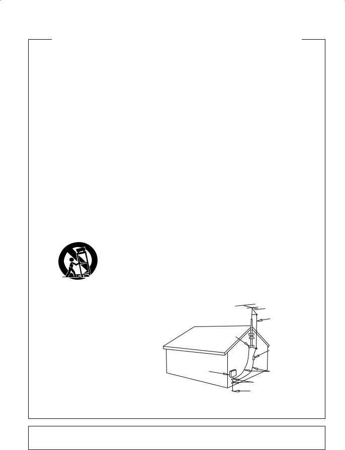
OUTDOOR ANTENNA GROUNDING — If an outside antenna or cable system is connected to the product, be sure the antenna or cable system is grounded so as to provide some protection against voltage surges and built-up static charges. Article 810 of the National Electrical Code, ANSI/NFPA 70, provides information with regard to proper grounding of the mast and supporting structure, grounding of the lead-in wire to an antenna discharge unit, size of grounding conductors, location of antenna-discharge unit, connection to grounding electrodes, and requirements for the grounding electrode. See Figure A.
LIGHTNING — For added protection for this product during a lightning storm, or when it is left unattended and unused for long periods of time, unplug it from the wall outlet and disconnect the antenna or cable system. This will prevent damage to the product due to lightning and power-line surges.
POWER LINES — An outside antenna system should not be located in the vicinity of overhead power lines or other electric light or power circuits, or where it can fall into such power lines or circuits. When installing an outside antenna system, extreme care should be taken to keep from touching such power lines or circuits as contact with them might be fatal.
OVERLOADING — Do not overload wall outlets, extension cords, or integral convenience receptacles as this can result in a risk of fire or electric shock.
OBJECT AND LIQUID ENTRY — Never push objects of any kind into this product through openings as they may touch dangerous voltage points or short-out parts that could result in a fire or electric shock. Never spill liquid of any kind on the product.
SERVICING — Do not attempt to service this product yourself as opening or removing covers may expose you to dangerous voltage or other hazards. Refer all servicing to qualified service personnel.
DAMAGE REQUIRING SERVICE — Unplug this product from the wall outlet and refer servicing to qualified service personnel under the following conditions:
•When the power-supply cord or plug is damaged.
•If liquid has been spilled, or objects have fallen into the product.
•If the product has been exposed to rain or water.
•If the product does not operate normally by following the operating instructions. Adjust only those controls that are covered by the operating instructions as an improper adjustment of other controls may result in damage and will often require extensive work by a qualified technician to restore the product to its normal operation.
•If the product has been dropped or damaged in any way.
•When the product exhibits a distinct change in
performance — this indicates a need for service. REPLACEMENT PARTS — When replacement parts are required, be sure the service technician has
used replacement parts specified by the manufacturer or have the same characteristics as the original part. Unauthorized substitutions may result in fire, electric shock, or other hazards.
SAFETY CHECK — Upon completion of any service or repairs to this product, ask the service technician to perform safety checks to determine that the product is in proper operating condition.
WALL OR CEILING MOUNTING — The product should not be mounted to a wall or ceiling.
HEAT — The product should be situated away from heat sources such as radiators, heat registers, stoves, or other products (including amplifiers) that produce heat.
ANTENNA
LEAD IN
WIRE
|
GROUND |
|
CLAMP |
|
ANTENNA |
|
DISCHARGE UNIT |
|
(NEC SECTION 810-20) |
ELECTRIC |
|
SERVICE |
GROUNDING CONDUCTORS |
EQUIPMENT |
(NEC SECTION 810-21) |
|
GROUND CLAMPS |
POWER SERVICE GROUNDING Fig. A ELECTRODE SYSTEM
(NEC ART 250, PART H)
NEC — NATIONAL ELECTRICAL CODE
D1-4-2-2_En
IMPORTANT NOTICE – THE SERIAL NUMBER FOR THIS EQUIPMENT IS LOCATED IN THE REAR.
PLEASE WRITE THIS SERIAL NUMBER ON YOUR ENCLOSED WARRANTY CARD AND KEEP IN A SECURE AREA. THIS IS FOR YOUR SECURITY.
For U.S. and Australia Model
C67-7-3_En
This product contains mercury. Disposal of this material may be regulated due to environmental considerations. For disposal or recycling information, please contact your local authorities or the Electronics Industries Alliance : www.eiae.org.
K057_En
This product is for general household purposes. Any failure due to use for other than household purposes (such as long-term use for business purposes in a restaurant or use in a car or ship) and which requires repair will be charged for even during the warranty period.
WARNING: Handling the cord on this product or cords associated with accessories sold with the product will expose you to lead, a chemical known to the State of California and other governmental entities to cause cancer and birth defects or other reproductive harm.
Wash hands after handling |
D36-P4_En |
Manufactured under license from Dolby Laboratories. “Dolby”, “Pro Logic”, and the double-D symbol are trademarks of Dolby Laboratories.
“DTS” and “DTS Digital Surround” are trademarks of Digital Theater Systems, Inc.
Selecting fine audio equipment such as the unit you’ve just purchased is only the start of your musical enjoyment. Now it’s time to consider how you can maximize the fun and excitement your equipment offers. This manufacturer and the Electronic Industries Association’s Consumer Electronics Group want you to get the most out of your equipment by playing it at a safe level. One that lets the sound come through loud and clear without annoying blaring or distortion-and, most importantly, without affecting your sensitive hearing.
Sound can be deceiving. Over time your hearing “comfort level” adapts to higher volumes of sound. So what sounds “normal” can actually be loud and harmful to your hearing. Guard against this by setting your equipment at a safe level BEFORE your hearing adapts.
To establish a safe level:
•Start your volume control at a low setting.
•Slowly increase the sound until you can hear it comfortably and clearly, and without distortion.
Once you have established a comfortable sound level:
• Set the dial and leave it there.
Taking a minute to do this now will help to prevent hearing damage or loss in the future. After all, we want you listening for a lifetime.
We Want You Listening For A Lifetime
Used wisely, your new sound equipment will provide a lifetime of fun and enjoyment. Since hearing damage from loud noise is often undetectable until it is too late, this manufacturer and the Electronic Industries Association’s Consumer Electronics Group recommend you avoid prolonged exposure to excessive noise. This list of sound levels is included for your protection.
Decibel
Level Example
30 Quiet library, soft whispers
40 Living room, refrigerator, bedroom away from traffic
50 Light traffic, normal conversation, quiet office
60 Air conditioner at 20 feet, sewing machine
70 Vacuum cleaner, hair dryer, noisy restaurant
80Average city traffic, garbage disposals, alarm clock at two feet.
THE FOLLOWING NOISES CAN BE DANGEROUS UNDER CONSTANT EXPOSURE
90 Subway, motorcycle, truck traffic, lawn mower
100 Garbage truck, chain saw, pneumatic drill
120 Rock band concert in front of speakers, thunderclap
140 Gunshot blast, jet plane
180 Rocket launching pad
Information courtesy of the Deafness Research Foundation.
S001_En

Contents
Contents
01 Before you start
Checking what’s in the box . . . . . . . . . . . . . . . . . . . . 6
Loading the batteries . . . . . . . . . . . . . . . . . . . . . . . . . 6
Operating range of remote control unit . . . . . . . . . . . 6
Ventilation . . . . . . . . . . . . . . . . . . . . . . . . . . . . . . . . . 6
02 Connecting up
Making cable connections. . . . . . . . . . . . . . . . . . . . . 7 Connecting to a TV and DVD recorder or player . . . . . 7 Connecting a satellite receiver or other digital
set-top box . . . . . . . . . . . . . . . . . . . . . . . . . . . . . . . . . 8
Connecting a tape deck or VCR . . . . . . . . . . . . . . . . . 8
Connecting antennas . . . . . . . . . . . . . . . . . . . . . . . . 9 Connecting the speakers . . . . . . . . . . . . . . . . . . . . . 10 Plugging in . . . . . . . . . . . . . . . . . . . . . . . . . . . . . . . 11
03 Controls and displays
Front panel . . . . . . . . . . . . . . . . . . . . . . . . . . . . . . . 12 Display. . . . . . . . . . . . . . . . . . . . . . . . . . . . . . . . . . . 13 Remote control . . . . . . . . . . . . . . . . . . . . . . . . . . . . 14
04 Surround sound setup
Introduction to home theater . . . . . . . . . . . . . . . . . . 16
Switching on . . . . . . . . . . . . . . . . . . . . . . . . . . . . . . 16
Quick setup using the Room Setup . . . . . . . . . . . . . 16 Setting speaker distances . . . . . . . . . . . . . . . . . . . . 17 Setting individual channel levels . . . . . . . . . . . . . . . 17
07 Additional information
Troubleshooting. . . . . . . . . . . . . . . . . . . . . . . . . . . . 25 Cleaning the unit . . . . . . . . . . . . . . . . . . . . . . . . . . . 26 Tuner step setting . . . . . . . . . . . . . . . . . . . . . . . . . . 26 Input attenuator setting . . . . . . . . . . . . . . . . . . . . . . 26 Resetting the receiver . . . . . . . . . . . . . . . . . . . . . . . 26 Specifications . . . . . . . . . . . . . . . . . . . . . . . . . . . . . 27
English
05 Listening to your system
Selecting a source . . . . . . . . . . . . . . . . . . . . . . . . . . 19
Using the Auto listening mode . . . . . . . . . . . . . . . . 19 Listening in surround sound . . . . . . . . . . . . . . . . . . 20
Listening in stereo . . . . . . . . . . . . . . . . . . . . . . . . . . 20 Using the Sound modes . . . . . . . . . . . . . . . . . . . . . 20 Using the tone controls . . . . . . . . . . . . . . . . . . . . . . 21
Listening through headphones . . . . . . . . . . . . . . . . 21 Dynamic Range Control setting . . . . . . . . . . . . . . . . 21
Dual Mono setting . . . . . . . . . . . . . . . . . . . . . . . . . . 22 Using the sleep timer. . . . . . . . . . . . . . . . . . . . . . . . 22
06 Using the tuner
Listening to the radio . . . . . . . . . . . . . . . . . . . . . . . . 23 Saving station presets . . . . . . . . . . . . . . . . . . . . . . . 23
Listening to station presets . . . . . . . . . . . . . . . . . . . 24
5
En

01 Before you start
Chapter 01:
Before you start
Checking what’s in the box
Please check that you've received the following supplied accessories:
•AM loop antenna
•FM wire antenna
•Dry cell batteries (AA size IEC R6) x2
•Remote control
•Warranty card
•These operating instructions
Loading the batteries
1 Open the battery compartment on the rear of the remote control
2 Insert the supplied batteries following the markings inside the battery compartment to align them correctly.
3 Replace the battery compartment cover.
6
 Important
Incorrect use of batteries may result in such hazards as leakage and bursting. Observe the following precautions:
•Never use new and old batteries together.
•Insert the plus and minus sides of the batteries properly according to the marks in the battery case.
•Batteries with the same shape may have different voltages. Do not use different batteries together.
•When disposing of used batteries, please comply with governmental regulations or environmental public instruction’s rules that apply in your country or area.
Operating range of remote control unit
The remote control may not work properly if:
•There are obstacles between the remote control and the receiver's remote sensor.
•Direct sunlight or fluorescent light is shining onto the remote sensor.
•The receiver is located near a device that is emitting infrared rays.
•The receiver is operated simultaneously with another infrared remote control unit.
30
30
21 ft. / 7m
Ventilation
The receiver should be properly ventilated to prevent overheating.
•Do not place anything directly on top of the receiver.
•Do not use the receiver on a thick carpet or other soft surface.
En
Connecting up
Chapter 02:
Connecting up
Making cable connections
Make sure not to bend the cables over the top of this unit (as shown in the illustration). If this happens, the magnetic field produced by the transformers in this unit may cause a humming noise from the speakers.
 Important
•Before making or changing any connections, switch off the power and disconnect the power cable from the AC outlet.
Audio cables (analog)
Use audio cables (not supplied) to connect audio components.
Connect red plugs to R (right) jacks, white plugs to L (left).
Be sure to insert completely.
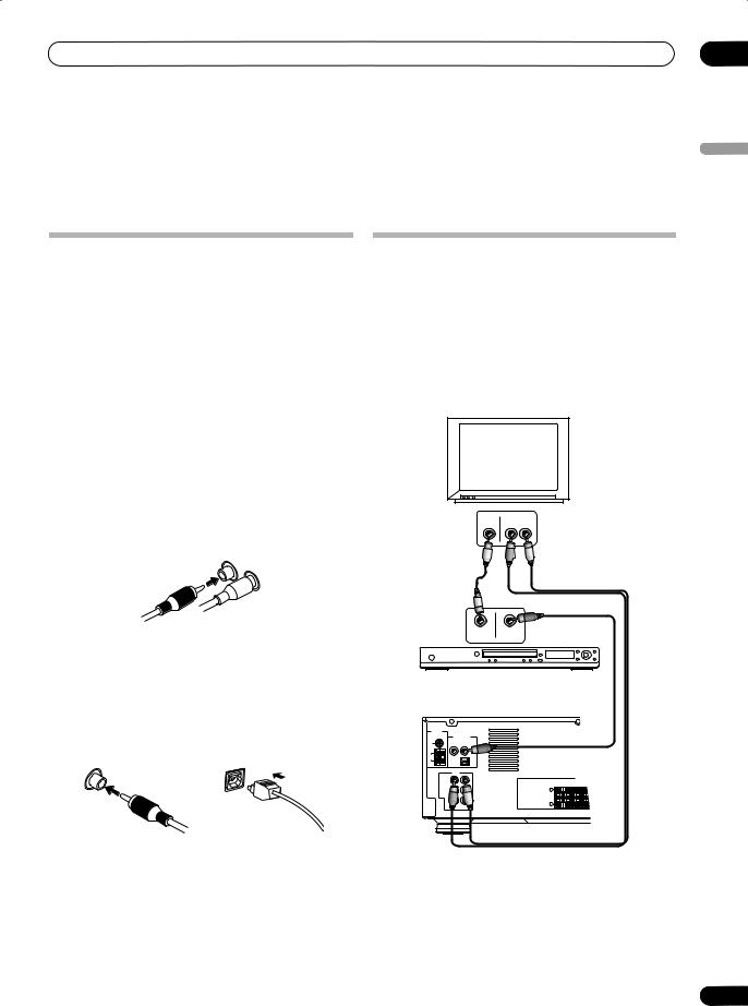
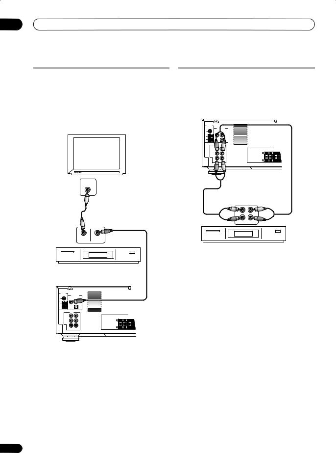
Connecting to a TV and DVD recorder or player
The diagram below shows the connections for a basic home theater setup of a TV, DVD recorder (or player) and this receiver.
Audio is output from the DVD recorder’s coaxial digital audio jack, while the video output goes to the TV. Also shown is a stereo analog audio connection from your TV to this receiver so you can enjoy sound from this receiver when watching TV programs.
TV |
VIDEO |
R AUDIO L |
|
IN |
OUT |
02
English
R |
L |
|
Coaxial and Optical digital audio cables
Coaxial digital audio cables (standard video cables can also be used) or optical cables are used to connect digital components to this receiver.
Be sure to insert completely.
Coaxial digital audio cable |
Optical cable |
(or standard video cable) |
|
VIDEO |
DIGITAL |
OUT |
OUT COAX |
DVD recorder/player
SX-315
ANTENNA
DIGITAL INPUT
(COAXIAL)
FM
UNBAL STB DVD/DVR 75Ω
|
|
AM |
(OPTICAL) |
LOOP |
|
|
DIGITAL |
AUDIO
SPEAKERS
TV IN |
|
FRONT |
|
SUB |
|
R |
CENTER |
||
|
L |
|
WOOFER |
|
IN |
+ |
|
|
|
OUT |
– |
|
|
|
|
|
|
|
|
R |
L |
|
|
|
•When inserting the plug of an optical cable, be careful not to damage the shutter protecting the optical jack.
•Do not bend optical cables around sharp corners as they may be damaged. When storing, coil loosely.
 Note
Note
•If your DVD recorder only has an optical digital output, you can still connect it to this receiver using the OPTICAL DIGITAL jack. In this case you will have to select the DIGITAL input function rather than
DVD.
7
En
02 Connecting up
Connecting a satellite receiver or other digital set-top box
The diagram below shows the connections for a digital set-top box (digital satellite receiver, decoder, cable box, digital terrestrial receiver, etc.). Connect the digital audio output of the set-top box (STB) to the STB input on this receiver. Connect the video output from the STB directly to a spare video input on your TV.
TV |
|
TV |
VIDEO |
|
IN |
Connecting a tape deck or VCR
The diagram below shows a tape deck or VCR connected to the receiver using two sets of stereo analog audio cables, one set for the audio input and one set for output from the receiver for recording.
SX-315 |
|
|
ANTENNA |
|
|
|
DIGITAL INPUT |
|
FM |
(COAXIAL) |
|
UNBAL |
STB |
DVD/DVR |
75Ω |
|
|
|
|
|
AM |
|
(OPTICAL) |
LOOP |
|
|
|
|
DIGITAL |
AUDIO |
|
|
|
|
TV IN |
|
|
SPEAKERS |
|
|
FRONT |
|
SUB |
|
|
R |
CENTER |
||
|
L |
|
WOOFER |
|
IN |
+ |
|
|
|
OUT |
– |
|
|
|
|
|
|
|
|
R |
L |
|
|
|
VIDEO |
DIGITAL |
OUT |
OUT COAX |
Set-top box (satellite receiver, etc.)
SX-315 |
|
|
|
ANTENNA |
|
|
|
|
DIGITAL INPUT |
||
FM |
(COAXIAL) |
||
STB |
DVD/DVR |
||
UNBAL |
|||
75Ω |
|
|
|
|
|
|
|
AM |
|
(OPTICAL) |
|
LOOP |
|
||
|
|
DIGITAL |
|
|
AUDIO |
|
|
TV IN |
|
|
SPEAKERS |
|
|
R |
FRONT |
CENTER |
SUB |
|
L |
|
WOOFER |
|
IN |
+ |
|
|
|
OUT

–
R L
L |
L |
R |
R |
IN |
OUT |
Tape deck or VCR
 Note
Note
•You can only record from analog audio sources (TV or FM/AM inputs). Audio from the digital inputs is not recordable from the analog outputs.
 Note
Note
•If your STB only has an optical digital output, you can still connect it to this receiver using the OPTICAL DIGITAL jack. In this case you will have to select the DIGITAL input function rather than STB.
8
En
Connecting up
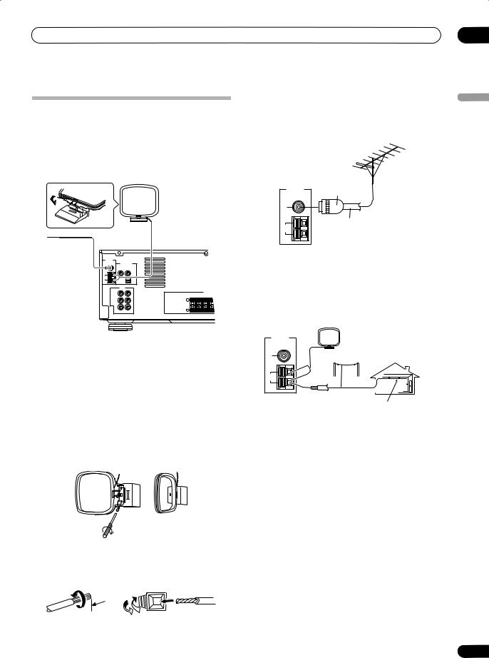
Connecting antennas
Connect the AM loop antenna and the FM wire antenna as shown below. To improve reception and sound quality, connect external antennas (see Using external antennas below). Always make sure that the receiver is switched off and unplugged from the wall outlet before making or changing any connections.
AM loop antenna
FM wire |
SX-315 |
antenna |
|
ANTENNA |
|
|
|
|
|
|
DIGITAL INPUT |
|
|
|
|
FM |
(COAXIAL) |
|
|
|
|
STB |
DVD/DVR |
|
|
|
|
UNBAL |
|
|
|
||
75Ω |
|
|
|
|
|
|
|
|
|
|
|
AM |
|
(OPTICAL) |
|
|
|
LOOP |
|
|
|
|
|
|
|
DIGITAL |
|
|
|
|
AUDIO |
|
|
|
|
|
TV IN |
|
|
SPEAKERS |
|
|
|
FRONT |
|
SUB |
|
|
|
R |
CENTER |
||
|
|
L |
|
WOOFER |
|
|
IN |
+ |
|
|
|
|
OUT |
– |
|
|
|
|
|
|
|
|
|
|
R |
L |
|
|
|
FM wire antenna
Connect the FM wire antenna and fully extend along a window frame or another suitable place that gives good reception.
AM loop antenna
Assemble the antenna and connect to the receiver. Attach (if necessary) and face in the direction that gives the best reception.
If you want to attach the loop antanna to a wall, assemble as shown below.
Antenna snap connectors
Twist the exposed wire strands together and insert into the hole, then snap the connector shut.
 3/8 in. (10mm)
Using external antennas
To improve FM reception
Connect an external FM antenna.
ANTENNA |
FM |
UNBAL |
75Ω |
|
AM |
LOOP |
One-touch
PAL-connector
75Ω coaxial cable
To improve AM reception
Connect a 15–18 ft. (5–6 m) length of vinyl-coated wire to the AM antenna terminal without disconnecting the supplied AM loop antenna.
For the best possible reception, suspend horizontally outdoors.
ANTENNA |
FM |
UNBAL |
75Ω |
|
AM |
LOOP |
Loop antenna
Outdoor antenna
15–18 ft. (5–6 m)
Indoor antenna (vinyl-coated wire)
02
English
9
En

02 Connecting up
Connecting the speakers
The diagram below shows a complete surround sound setup of six speakers set up in a typical configuration. For the best sound, try to follow this setup in your room as closely as possible.
Make sure the positive (colored) and negative (black) terminals on the receiver match those on the speakers. You can use speakers with a nominal impedance between 6–16Ω.
|
|
Red tab – Front right (R) |
|
|
White tab – Front left (L) |
|
+ |
Green tab – Center (C) |
|
Purple tab – Subwoofer |
|
SX-315 |
– |
Gray tab – Surround right (R) |
|
Blue tab – Surround left (L) |
ANTENNA |
|
|
|
DIGITAL INPUT |
|
FM |
(COAXIAL) |
|
UNBAL |
STB |
DVD/DVR |
75Ω |
|
|
|
|
|
AM |
|
(OPTICAL) |
LOOP |
|
|
|
|
DIGITAL |
|
AUDIO |
|
TV IN |
|
|
|
|
|
|
R |
L |
WOOFER R |
L |
OUT |
IN |
+ |
|
|
+ |
|
|
|
|
|||
|
|
|
|
L |
|
OUT |
– |
|
|
– R |
|
|
|
|
|
||
R |
L |
|
|
|
|
Wireless (XW-HTP550 set only)
+ |
+ |
– |
– |
Front R. |
Front L. |
+ |
– |
Center
+ |
– |
Subwoofer |
+ |
+ |
– |
– |
Surround R. |
Surround L. |
Hints on speaker placement
Speakers are usually designed with a particular placement in mind. Some are designed to be floorstanding, while others should be placed on stands to sound their best. Some should be placed near a wall; others should be placed away from walls. We have provided a few tips on getting the best sound from your speakers (following), but you should also follow the guidelines on placement that the speaker manufacturer provided with your particular speakers to get the most out of them.
•Place the front left and right speakers at equal distances from the TV.
•When placing speakers near the TV, we recommend using magnetically shielded speakers to prevent possible interference, such as discoloration of the picture when the TV is switched on. If you do not have magnetically shielded speakers and notice discoloration of the TV picture, move the speakers farther away from the TV.
•Place the center speaker above or below the TV so that the sound of the center channel is localized at the TV screen.
•If possible, place the surround speakers slightly above ear level.
10
En
Connecting up
•Try not to place the surround speakers further away from the listening position than the front and center speakers. Doing so can weaken the surround sound effect.
 Caution
•If you choose to install the center speaker on top of the TV, be sure to secure it with putty, or by other suitable means, to reduce the risk of damage or injury resulting from the speaker falling from the TV in the event of external shocks such as earthquakes.
•Make sure no exposed speaker wire is touching the rear panel, this may cause the receiver to turn off automatically.
•These speaker terminals are hazardous when live. To prevent the risk of electric shock when connecting or disconnecting the speaker cables, disconnect the power cable.
Plugging in
After making sure that everything is connected properly, connect the attached power cable to a wall outlet.
Power cord caution
Handle the power cord by the plug. Do not pull out the plug by tugging the cord and never touch the power cord when your hands are wet as this could cause a short circuit or an electric shock. Do not place the unit, a piece of furniture, etc., on the power cord, or pinch the cord. Never make a knot in the cord or tie it with other cords. The power cords should be routed such that they are not likely to be stepped on. A damaged power cord can cause a fire or give you an electrical shock. Check the power cord once in a while. When you find it damaged, ask your nearest Pioneer authorized service center or your dealer for a replacement.
02
English
About the wireless speaker outputs
To the right of the main speaker terminals there is a pair of WIRELESS OUT jacks for use with the Pioneer XWHTP550 wireless speaker system. Please do not connect any other component to these jacks.
For more information on using a wireless speaker with this receiver, please see the operating instructions that come with the wireless speaker system.
11
En
03 Controls and displays
Chapter 03:
Controls and displays
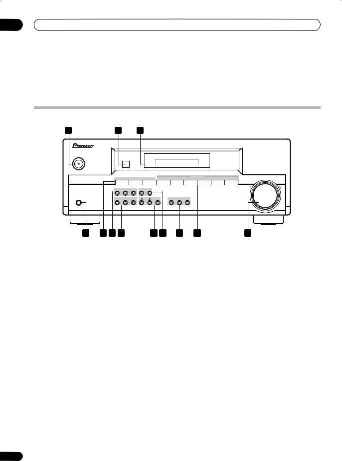
Front panel
1 |
2 |
3 |
AUDIO MULTI-CHANNEL RECEIVER SX-315
STANDBY/ON
INPUT SELECTOR
– |
STATION + |
CLASS |
FM/AM |
TAPE/VCR |
TV |
DIGITAL |
STB |
DVD/DVR |
MASTER VOLUME |
|
|
|
|
|
|
|
|
DOWN |
UP |
|
AUTO |
SURROUND |
STEREO |
– TUNING |
+ |
|
|
|
|
PHONES |
SYSTEM |
TUNER |
CHANNEL |
|
|
SOUND |
SOUND |
|
|
|
SETUP |
EDIT |
LEVEL |
|
ENTER |
MODE OFF |
MODE |
TONE |
|
4 |
5 |
6 |
7 |
8 |
9 |
10 |
11 |
12 |
1 STANDBY/ON
Switches the receiver between on and standby (page 16).
2 Remote sensor
Receives the signals from the remote control (page 6).
3 Display
See Display on page 13 for details.
4 PHONES jack
Use to connect headphones. When the headphones are connected, there is no sound output from the speakers (page 21).
5Tuner preset selection buttons
STATION +/–
Selects station presets when using the tuner (page 24).
CLASS
Switches between the three banks (classes) of station presets (page 23).
6Listening mode buttons
AUTO
Press for automatic decoding (page 19).
SURROUND
Use to switch between the various surround modes (page 19).
STEREO
7SYSTEM SETUP
Press to access the System Setup menu (page 17, 21, 26).
TUNER EDIT
Use to memorize and name a station for recall using the STATION +/– buttons (page 23).
CH LEVEL
Press to set up the channel levels for surround sound (page 17).
8< / > and ENTER
Use to navigate menus and change settings.
9 TUNING +/–
Use to tune to radio stations (page 23).
10Listening mode buttons
SOUND MODE OFF
Press to turn off the current Sound mode (page 20).
SOUND MODE
Press to select a Sound mode (page 20).
TONE
Press to access the bass and treble controls, which you can then adjust with the remote’s BASS and TREBLE buttons (page 21).
11Input select buttons
Press to select an input source (page 19).
Switches to stereo playback (page 20). |
12 MASTER VOLUME |
12
En
Controls and displays
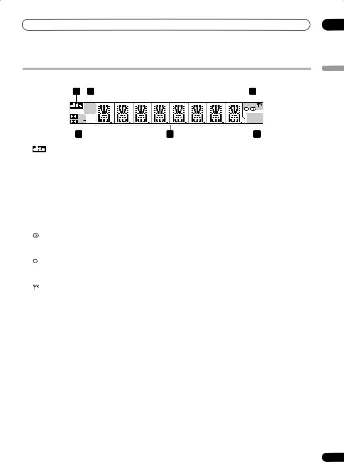
Display
1 |
2 |
3 |
|
|
5ch |
|
|
|
ST |
|
|
|
PCM |
TONE |
|
D |
|
||
|
SOUND |
||
PLII |
|||
SLEEP |
|||
4
1
Lights when the receiver is decoding a DTS signal.
25ch
Lights when the receiver is in 5ch stereo mode.
ST
Lights when the receiver is in Stereo mode.
PCM
Lights when the digital input is Linear PCM format (CD Audio, etc.).
3TUNER indicators
Lights when a stereo FM broadcast is being received in auto stereo mode.
Lights when the mono mode is set using the MPX button (page 23).
5 |
6 |
42 D
Lights when the receiver is decoding a Dolby Digital signal.
2 PL II
Lights when the receiver is using Dolby Pro Logic II decoding.
5Character display
6TONE
Lights when the receiver is in tone mode.
SOUND
Lights when the receiver is in sound mode.
SLEEP
Lights when the receiver is in sleep mode.
Lights when a broadcast is being received.
03
English
13
En
03 Controls and displays
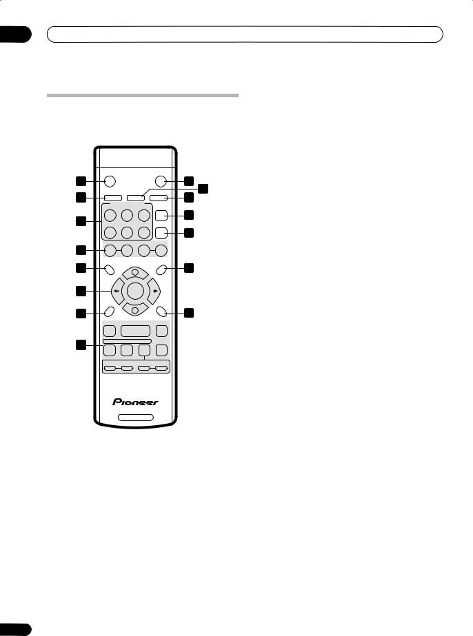
Remote control
|
STANDBY/ON |
|
MUTE |
|
||
1 |
|
|
|
|
2 |
|
|
SLEEP |
STATUS |
DIMMER |
3 |
||
4 |
5 |
|||||
INPUT SELECTOR |
TUNER |
|||||
|
|
|||||
|
DIGITAL |
STB |
DVD/DVR |
EDIT |
|
|
7 |
|
|
|
|
6 |
|
FM/AM |
TAPE/VCR |
TV |
CLASS |
|
||
|
|
|
|
|
8 |
|
9 |
TUNING |
STATION |
|
|||
– |
+ |
– |
+ |
|
||
|
SYSTEM |
VOLUME |
|
|
||
10 |
SETUP |
CH LEVEL |
11 |
|||
|
+ |
|
||||
|
|
|
|
|||
12 |
|
ENTER |
|
|
||
|
ROOM |
|
|
TEST |
|
|
|
SETUP |
– |
TONE |
|
||
13 |
|
|
14 |
|||
|
|
|
|
|||
|
AUTO |
SURROUND |
STEREO |
|
||
15 |
OFF |
SOUND |
TONE |
MPX |
|
|
|
|
|
|
|
||
|
BASS |
TREBLE |
|
|||
|
– |
+ |
– |
+ |
|
|
|
|
RECEIVER |
|
|
||
14
1 STANDBY/ON
This switches between standby and on for this receiver (page 16).
2 MUTE
Press to mute the sound (press again, or adjust the volume, to restore the sound).
3 STATUS
Press to display the current surround mode and sound mode.
4 SLEEP
Use to put the receiver in sleep mode and select the amount of time before the receiver turns off (page 22).
5 DIMMER
Press repeatedly to set the front panel display brightness.
6 TUNER EDIT
Use to memorize and name a station for recall using the STATION +/– buttons (page 23).
7 INPUT SELECTOR buttons
Press to select an input source (page 19).
DIGITAL
Press to select the optical digital input.
STB
Press to select the STB (set-top box) input (for cable/ satellite receivers, etc.).
DVD/DVR
Press to select the DVD player/recorder input.
FM/AM
Press to select the FM or AM band for the built-in tuner.
TAPE/VCR
Press to select the analog tape/VCR input.
TV
Press to select the TV audio input.
8 CLASS
Switches between the three banks (classes) of radio station presets (page 23).
9Radio tuning controls
TUNING +/–
Use to manually tune into radio stations (page 24).
STATION +/–
Use to tune to preset stations (page 24).
10SYSTEM SETUP
Press to access the System Setup menu (page 17, 21, 26).
11 CH LEVEL
Press to set up the channel levels for surround sound (page 17).
En

Controls and displays
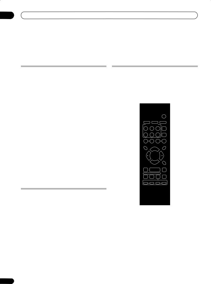
12/ (cursor left/right), VOLUME +/– and ENTER
Use to navigate menus and adjust the volume.
13ROOM SETUP
Press to set up surround sound using the Room Setup presets (page 16).
14 TEST TONE
Sounds the test tone when setting up the surround sound of the receiver (page 17).
15Listening mode buttons
AUTO
Press for automatic decoding based on the source material (page 19).
SURROUND
Press to switch between the various Pro Logic II and other listening mode options (page 20).
STEREO
Switches to stereo playback using only the front left and right speakers (page 20).
OFF
Switches off the Sound mode (page 20).
SOUND
Press to select a Sound mode (page 20).
TONE
Use in conjuction with the BASS and TREBLE buttons below (page 21).
MPX
Switches between stereo and mono reception of FM broadcasts. If the signal is weak then switching to mono will improve the sound quality (page 23).
BASS +/–
Use with the TONE button above to adjust the bass (page 21).
TREBLE +/–
Use with the TONE button above to adjust the treble (page 21).
03
English
15
En
04 Surround sound setup
Chapter 04:
Surround sound setup
Introduction to home theater
You are probably used to using stereo equipment to listen to music, but may not be used to home theater systems that give you many more options (such as surround sound) when listening to soundtracks.
Home theater refers to the use of multiple audio tracks to create a surround sound effect, making you feel like you're in the middle of the action or concert. The surround sound you get from a home theater system depends not only on the speakers you have set up in your room, but also on the source and the sound settings of the receiver.
DVD-Video has become the basic source material for home theater due to its size, quality, and ease of use. Depending on the DVD, you can have up to seven different audio tracks coming from one disc, all of them being sent to different speakers in your system. This is what creates a surround sound effect and gives you the feeling of ‘being there’.
This receiver will automatically decode Dolby Digital, DTS, or Dolby Surround DVD-Video discs, according to your speaker setup. In most cases, you won’t have to make changes for realistic surround sound, but other possibilities (like listening to a CD with multichannel surround sound) are explained in Listening to your system on page 19.
Switching on
Use the STANDBY/ON button on the front panel or the remote control to switch the receiver on or into standby.
Remember that when the receiver is in standby it still uses a small amount of power (0.45 W). Unplug from the wall outlet to completely disconnect the power. The receiver will retain its settings for about four weeks when unplugged.
Quick setup using the Room Setup
The Room Setup feature gives you a very simple way to set up your receiver for good surround sound by setting the room size and your seating position in the room.
You can make more detailed settings for surround sound later if you want, setting individual channel levels and speaker distances. See below for more details.
STANDBY/ON |
|
ENTER |
ROOM |
SETUP |
RECEIVER |
1If the receiver isn’t already on, press
STANDBY/ON (remote or front panel) to switch on.
2Press ROOM SETUP then ENTER.
The display shows the current Room Setup setting.
•If any of the speaker distance settings have been changed (see Setting speaker distances below) then the display blinks ROOM SET.
3 Use the ROOM SETUP button to select a room size setting, then press ENTER.
Select from:
•Room S – Smaller than average room (approx. 3.5 x 4.5m)
•Room M – Average room (approx. 5.5 x 6.0m)
16
En
 Loading...