


 Loading...
HTP-500 5.1 ch Surround System
SX-SWR1
S-SWR500
Audio/Video Multi-channel Receiver Subwoofer
Speaker System

IMPORTANT
CAUTION
RISK OF ELECTRIC SHOCK
DO NOT OPEN
The lightning flash with arrowhead symbol, within an equilateral triangle, is intended to alert the user to the presence of uninsulated “dangerous voltage” within the product’s enclosure that may be of sufficient magnitude to constitute a risk of electric shock to persons.
CAUTION:
TO PREVENT THE RISK OF ELECTRIC SHOCK, DO NOT REMOVE COVER (OR BACK). NO USER-SERVICEABLE PARTS INSIDE. REFER SERVICING TO QUALIFIED SERVICE PERSONNEL.
The exclamation point within an equilateral triangle is intended to alert the user to the presence of important operating and maintenance (servicing) instructions in the literature accompanying the appliance.
D3-4-2-1-1_A1_En
WARNING
This equipment is not waterproof. To prevent a fire or shock hazard, do not place any container filled with liquid near this equipment (such as a vase or flower pot) or expose it to dripping, splashing, rain or moisture.
D3-4-2-1-3_A1_En
WARNING
Before plugging in for the first time, read the following section carefully.
The voltage of the available power supply differs according to country or region. Be sure that the power supply voltage of the area where this unit will be used meets the required voltage (e.g., 230 V or 120 V) written on the rear panel.
D3-4-2-1-4*_A1_En
WARNING
To prevent a fire hazard, do not place any naked flame sources (such as a lighted candle) on the equipment.
D3-4-2-1-7a_A1_En
VENTILATION CAUTION
When installing this unit, make sure to leave space around the unit for ventilation to improve heat radiation (at least 10 cm at top, 10 cm at rear, and 10 cm at each side).
WARNING
Slots and openings in the cabinet are provided for ventilation to ensure reliable operation of the product, and to protect it from overheating. To prevent fire hazard, the openings should never be blocked or covered with items (such as newspapers, table-cloths, curtains) or by operating the equipment on thick carpet or a bed.
D3-4-2-1-7b*_A1_En
Operating Environment
Operating environment temperature and humidity: +5 °C to +35 °C (+41 °F to +95 °F); less than 85 %RH (cooling vents not blocked)
Do not install this unit in a poorly ventilated area, or in locations exposed to high humidity or direct sunlight (or strong artificial light)
POWER-CORD CAUTION
Handle the power cord by the plug. Do not pull out the plug by tugging the cord and never touch the power cord when your hands are wet as this could cause a short circuit or electric shock. Do not place the unit, a piece of furniture, etc., on the power cord, or pinch the cord. Never make a knot in the cord or tie it with other cords. The power cords should be routed such that they are not likely to be stepped on. A damaged power cord can cause a fire or give you an electrical shock. Check the power cord once in a while. When you find it damaged, ask your nearest PIONEER authorized service center or your dealer for a replacement.
S002*_A1_En
If the AC plug of this unit does not match the AC outlet you want to use, the plug must be removed and appropriate one fitted. Replacement and mounting of an AC plug on the power supply cord of this unit should be performed only by qualified service personnel. If connected to an AC outlet, the cut-off plug can cause severe electrical shock. Make sure it is properly disposed of after removal.
The equipment should be disconnected by removing the mains plug from the wall socket when left unused for a long period of time (for example, when on vacation).
D3-4-2-2-1a_A1_En
CAUTION
The  STANDBY/ON switch on this unit will not completely shut off all power from the AC outlet. Since the power cord serves as the main disconnect device for the unit, you will need to unplug it from the AC outlet to shut down all power. Therefore, make sure the unit has been installed so that the power cord can be easily unplugged from the AC outlet in case of an accident. To avoid fire hazard, the power cord should also be unplugged from the AC outlet when left unused for a long period of time (for example, when on vacation).
D3-4-2-2-2a*_A1_En
D3-4-2-1-7c*_A1_En

Replacement and mounting of an AC plug on the power supply cord of this unit should be performed only by qualified service personnel.
IMPORTANT: THE MOULDED PLUG
This appliance is supplied with a moulded three pin mains plug for your safety and convenience. A 5 amp fuse is fitted in this plug. Should the fuse need to be replaced, please ensure that the replacement fuse has a rating of 5 amps and that it is approved by ASTA or BSI to BS1362.
Check for the ASTA mark  or the BSI mark
  on the body of the fuse.
If the plug contains a removable fuse cover, you must ensure that it is refitted when the fuse is replaced. If you lose the fuse cover the plug must not be used until a replacement cover is obtained. A replacement fuse cover can be obtained from your local dealer.
If the fitted moulded plug is unsuitable for your socket outlet, then the fuse shall be removed and the plug cut off and disposed of safely. There is a danger of severe electrical shock if the cut off plug is inserted into any 13 amp socket.
If a new plug is to be fitted, please observe the wiring code as shown below. If in any doubt, please consult a qualified electrician.
IMPORTANT: The wires in this mains lead are coloured in accordance with the following code: Blue : Neutral Brown : Live
As the colours of the wires in the mains lead of this appliance may not correspond with the coloured markings identifying the terminals in your plug, proceed as follows;
The wire which is coloured BLUE must be connected to the terminal which is marked with the letter N or coloured BLACK.
The wire which is coloured BROWN must be connected to the terminal which is marked with the letter L or coloured RED.
How to replace the fuse: Open the fuse compartment with a screwdriver and replace the fuse.
D3-4-2-1-2-2*_A1_En
This product is for general household purposes. Any failure due to use for other than household purposes (such as long-term use for business purposes in a restaurant or use in a car or ship) and which requires repair will be charged for even during the warranty period.
K041_A1_En
(Symbol examples for batteries)
These symbols are only valid in the European Union.
Pb |
K058c_A1_En |
Manufactured under license from Dolby Laboratories. “Dolby”, “Pro Logic”, and the double-D symbol are trademarks of Dolby Laboratories.
Manufactured under license under U.S. Patent #’s: 5,451,942; 5,956,674; 5,974,380; 5,978,762; 6,226,616; 6,487,535; 7,212,872; 7,333,929; 7,392,195; 7,272,567 & other U.S. and worldwide patents issued & pending. DTS is a registered trademark and the DTS logos, Symbol, DTS-HD and DTS-HD Master Audio are trademarks of DTS, Inc. © 1996-2008 DTS, Inc. All Rights Reserved.

1 Setup Guide
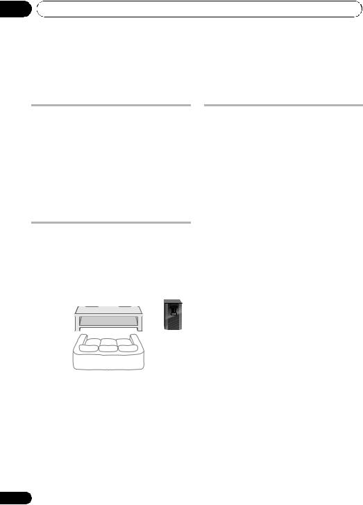
What’s in the box
Please confirm that the following items are all supplied.
Receiver subwoofer (SX-SWR1) box
Receiver subwoofer x1
FM wire antenna x1
SYSTEM |
SOURCE |
|
|
SYSTEM |
TV CONTROL |
|
|
|
INPUT |
|
|
|
CH |
|
|
|
BD MENU |
Dry cell batteries |
Large non-skid pads |
|
VOL |
|
|
|
|
(AAA size IEC R03) x2 |
(for receiver subwoofer) x4 |
MUTE |
|
DISPLAY |
|
ENTER |
|
SURROUND SYSTEM |
Remote control x1 |
Microphone (for Auto MCACC setup) x1
Power cords x2
Operating instructions (This document)
Speakers (S-SWR500) box
A  B
B 
Front speakers x2
C  C
C 
Center speakers x2
D  E
E 
Speaker cables
(for front speaker x2, for center speaker x1, for surround speaker x2)
Small non-skid pads
(for speaker stand bases) x18
Surround speakers x2 |
Brackets x2 |
Mounting brackets x6 |
Screws x8 |
Commercially available
4
En

Connection
HDMI OUT
HDMI IN
1


VIDEO IN
C |
E |
D |
B |
A |
C |
C |
|
|
|
A FRONT-L |
|
|
White |
A |
B |
B FRONT-R |
|
|
Red |
|
|
C CENTER |
|
|
Green |
|
|
D SURROUND-L |
|
|
Blue |
|
|
E SURROUND-R |
D |
|
Grey |
|
E |
A B C D E
C  C
C
A  B
B
Nederlands Español Italiano Deutsch Français English
6For enjoying your self (MCACC)
5
En
2 For enjoying your self (MCACC)
|
|
|
SYSTEM |
|
TV CONTROL |
System Setup |
|
|
|
|
|
|
|
|
|
|
|
|
INPUT |
1.Auto MCACC |
|
||
|
|
|
|
|
|
|
|
|
|
|
|
|
CH |
2.Manual SP Setup |
|
|
|
|
|
|
|
|
Return |
|
|
|
ENTER |
|
|
||
|
|
|
|
|
|
1.Auto MCACC |
|
|
|
|
|
|
|
Now Analyzing |
|
|
|
|
|
|
|
Environment Check |
|
|
|
|
|
|
|
Ambient Noise |
|
|
|
|
ENTER |
|
Speaker YES/NO |
|
|
|
|
|
|
|
|
|
Return |
|
|
|
|
|
? |
33-35 |
|
|
VIDEO1 |
|
|
|
|
|
|
|
|
On |
1.Auto MCACC |
|
System Setup |
|
|
|
|
Check! |
1.Auto MCACC |
||||
|
|
|
|||||
|
|
|
Front |
[ |
YES ] |
2.Manual SP |
Setup |
|
|
|
|
|
|||
|
|
|
Center |
[ |
YES ] |
|
|
|
|
|
Surr |
[ |
YES ] |
|
|
|
|
|
Surr. Back |
[YESx2] |
|
|
|
|
|
|
Subwoofer |
[ |
YES ] |
|
|
|
|
|
10:Next |
|
OK |
|
|
|
|
|
|
Return |
|
Return |
|
SYSTEM |
SOURCE |
|
On |
|
|
|
|
|
|
|
|
|
|
|
|
6
En

3 Home theater
|
BD/DVD |
|
|
Radio |
|
|
|
|
VIDEO1 |
|
|
|
|
|
English |
|
|
|
SYSTEM |
|
SOURCE |
On |
|
|
|
|
|
|
|||
|
|
|
|
|
|
||
|
|
|
|
|
|
|
|
|
On |
|
|
|
|
|
Français |
|
|
|
SYSTEM |
TV CONTROL |
|
||
|
|
|
|
INPUT |
|
|
|
|
|
|
|
|
CH |
TUNER |
|
|
|
|
|
|
|
||
SYSTEM |
SOURCE |
On |
|
|
|
|
|
|
|
|
|
|
|
||
|
|
|
|
|
|
|
|
|
|
|
|
DIMMER SIGNAL SEL |
VOL |
|
|
|
|
|
|
BD MENU |
|
|
Deutsch |
SYSTEM |
TV CONTROL |
|
|
|
|
|
|
|
INPUT |
|
|
|
|
|
|
|
CH |
BD/DVD |
|
|
|
|
|
|
|
|
|
|
|
||
|
|
|
|
ENTER |
|
|
|
|
|
|
SYSTEM |
|
|
|
Italiano |
|
|
|
|
SOURCE |
Off |
|
|
|
|
|
|
|
|
|
|
|
|
|
|
|
|
|
Español |
|
|
|
ENTER |
|
|
|
Nederlands |
|
|
|
|
|
|
|
|
|
Off |
|
|
|
|
|
|
SYSTEM |
SOURCE |
Off |
|
|
|
|
|
|
|
55 |
|
|
|
|
|
|
|
|
|
|
|
|
|
|
|
|
|
|
|
|
7 |
|
|
|
|
|
|
|
En |

Thank you for buying this Pioneer product.
Please read through these operating instructions so that you will know how to operate your model properly. After you have finished reading the instructions, put them in a safe place for future reference.
Contents |
|
Setup Guide ..................................... |
4 |
For enjoying your self (MCACC)..... |
6 |
Home theater................................... |
7 |
01 Speaker Setup
Safety precautions when setting up. . . . . .10 Home theater sound setup . . . . . . . . . . . .10 Preparing the speakers . . . . . . . . . . . . . . .10 Wall mounting the speakers . . . . . . . . . . .12
Before mounting . . . . . . . . . . . . . . . . . . .12
Additional notes on speaker placement. . .13
02 Connecting up
Rear panel . . . . . . . . . . . . . . . . . . . . . . . . .14
Making cable connections. . . . . . . . . . . . .15 About video outputs connection . . . . . . .15
HDMI cables . . . . . . . . . . . . . . . . . . . . . .15 Analog audio cables . . . . . . . . . . . . . . . .16 Digital audio cables. . . . . . . . . . . . . . . . .16
Connect your TV (For TV audio) . . . . . . . . .17 Connecting your TV and playback components . . . . . . . . . . . . . . . . . . . . . . .18
Connecting using HDMI . . . . . . . . . . . . .18 Connecting your component with no
HDMI terminal . . . . . . . . . . . . . . . . . . . .19
Connecting an HDD/DVD recorder, VCR
and other video sources. . . . . . . . . . . . . . .20 Connecting a satellite receiver or other digital set-top box . . . . . . . . . . . . . . . . . . .21
Connecting other audio components. . . . .22 Connecting to the front panel video
terminal . . . . . . . . . . . . . . . . . . . . . . . . . . .23
Connecting an iPod/iPhone . . . . . . . . . . . .23 Connecting using an optional cable . . . .23 Connecting a USB device . . . . . . . . . . . . .24 Connecting the FM antenna . . . . . . . . . . .24 Connecting external antennas. . . . . . . . .24
Use the PRE OUT outputs to connect
the surround back speakers . . . . . . . . . . .25 Plugging in the system . . . . . . . . . . . . . . .25
03 Controls and displays
Front panel . . . . . . . . . . . . . . . . . . . . . . . . 26 Display . . . . . . . . . . . . . . . . . . . . . . . . . . 27 Remote control . . . . . . . . . . . . . . . . . . . . . 29
Putting the batteries in the remote
control . . . . . . . . . . . . . . . . . . . . . . . . . . 32
Using the remote control . . . . . . . . . . . . 32
04 Getting started
Changing the TV format setting. . . . . . . . . 33 Changing the frequency step . . . . . . . . . . 33 Automatically setting up for surround
sound (MCACC) . . . . . . . . . . . . . . . . . . . . 33
Other problems when using
the Auto MCACC Setup . . . . . . . . . . . . . 35
Basic operation. . . . . . . . . . . . . . . . . . . . . 36
Choosing the input signal. . . . . . . . . . . . 36
05 iPod/USB playback
Playing an iPod . . . . . . . . . . . . . . . . . . . . . 37 iPod playback . . . . . . . . . . . . . . . . . . . . . 37
Watching photos and video content . . . . 39
About iPod . . . . . . . . . . . . . . . . . . . . . . . 39 Playing a USB device . . . . . . . . . . . . . . . . 40
Basic playback controls . . . . . . . . . . . . . 40 Compressed audio compatibility. . . . . . . 41
06 Using the tuner
Listening to the radio . . . . . . . . . . . . . . . . 42 Improving FM stereo sound . . . . . . . . . . 42 Saving station presets . . . . . . . . . . . . . . . . 42 Listening to station presets. . . . . . . . . . . 43 Naming preset stations. . . . . . . . . . . . . . 43
07 Listening to your system
Selecting Listening mode . . . . . . . . . . . . . 44
Auto playback . . . . . . . . . . . . . . . . . . . . . . 44
Listening in surround sound . . . . . . . . . . . 44 Using the Advanced surround effects. . . 45
Listening in stereo. . . . . . . . . . . . . . . . . . . 45
Using Front Stage Surround Advance . . . . 45
Using Stream Direct . . . . . . . . . . . . . . . . . 46
Using the Sound Retriever . . . . . . . . . . . . 46
8
En

Listening with Acoustic Calibration EQ . . 46 Better sound using Phase Control . . . . . . 46 Functions when surround back speakers
are connected . . . . . . . . . . . . . . . . . . . . . 47
Surround sound mode. . . . . . . . . . . . . . 47 Using surround back channel
processing. . . . . . . . . . . . . . . . . . . . . . . 48
Setting the Up Mix function . . . . . . . . . . 48 Setting the Audio options. . . . . . . . . . . . . 49
08 The System Setup menu
Using the System Setup menu. . . . . . . . . 52 Manual speaker setup . . . . . . . . . . . . . . . 52
Speaker Setting . . . . . . . . . . . . . . . . . . . 53 Channel Level . . . . . . . . . . . . . . . . . . . . 53 Speaker Distance. . . . . . . . . . . . . . . . . . 54
09 Controlling the rest of your system
Setting the remote to control other components. . . . . . . . . . . . . . . . . . . . . . . 55
Selecting preset codes directly. . . . . . . . . 55 Clearing all the remote control settings . . 55
Controls for TVs . . . . . . . . . . . . . . . . . . . . 56
Controls for other components . . . . . . . . 57
Preset Code List . . . . . . . . . . . . . . . . . . . . 58
10 Additional information
Troubleshooting . . . . . . . . . . . . . . . . . . . . 63 HDMI. . . . . . . . . . . . . . . . . . . . . . . . . . . 65
Important information regarding
the HDMI connection . . . . . . . . . . . . . . 65 iPod messages . . . . . . . . . . . . . . . . . . . 66 USB messages . . . . . . . . . . . . . . . . . . . 66
Resetting the main unit . . . . . . . . . . . . . . 66
Specifications . . . . . . . . . . . . . . . . . . . . . 67
SX-SWR1 Receiver subwoofer . . . . . . . . 67 S-SWR500 Speaker system . . . . . . . . . . 67
Cleaning the unit . . . . . . . . . . . . . . . . . . . 68
Nederlands Español Italiano Deutsch Français English
9
En
01 Speaker Setup
Chapter 1
Speaker Setup
Safety precautions when setting up
When assembling the speakers, lay them down flat on their side to avoid accidents or injury. Make sure to use a stable surface when assembling, setting up, and placing the speakers.
If the speakers are to be used in a stacked configuration, always use the provided brackets to secure them together (page 11).
Home theater sound setup
This is a standard multichannel surround sound speaker setup for optimal 5.1 channel home theater sound. The front left and right speakers should be about 1.8 m to 2.7 m apart.
Preparing the speakers
1 Attach the non-skid pads to the base of each speakers and the receiver subwoofer.
For front, center and surround speakers:
Use the supplied adhesive to attach three pads to the base (bottom) of each speaker.
Small non-skid pads
For subwoofer:
Use the supplied adhesive to attach four large pads to the base of subwoofer.
Center |
Center |
Front left |
Large non-skid pads |
|
Front right |
Subwoofer |
|
Listening position |
Surround left |
Surround right |
*When center speakers are placed in the center. |
|
Front left |
Front right |
Center |
10
En
Speaker Setup |
01 |
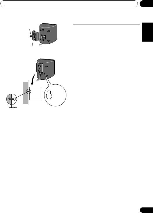
2 (When mounting center speakers to right and left) Stack the speakers and fix with the bracket.
Each speaker is provided with a color-coded indicator on the model label on the rear side to assist identification. Refer to the color indicators and install the speakers correctly.
As shown in the illustration, stack the speakers. Align the bracket with the respective upper and lower screw holes as shown in each figure below and fasten the screws securely.
Model label |
Left |
|
|
Right |
|
Green |
Center |
|
Green |
|
speaker |
|||
|
|
|
||
Color indicator |
White |
Front |
|
Red |
|
speaker |
|
||
|
|
|
|
|
Bracket |
|
|
Center |
|
|
|
|
||
|
|
|
speaker |
|
|
|
|
Front |
|
|
|
|
speaker |
|
Screw |
|
|
|
|
 Caution
•Do not attempt to carry the speakers when they are connected with the bracket. Doing so may cause damage to the bracket or worsen damage to the bracket and speakers in the event they are dropped.
3 Connect each speaker. |
English |
||
Connect the wires to the speaker. Each |
|||
|
|||
speaker in the illustration can be identified by |
|
||
means of the color-coded indicator provided |
|
||
on the rear-surface label. |
|
||
Front left: White |
Français |
||
Front right: Red |
|||
|
|||
Center: Green |
|
||
Surround left: Blue |
|
||
Surround right: Gray |
|
||
Match the color-coded wire with the color |
|
||
indicator on the label, then insert the color- |
Deutsch |
||
coded wire into the red (+) side and the other |
|||
|
|||
wire into the black (–) side. |
|
||
Black(–) |
Red (+) |
|
|
|
Color-coded wire |
|
|
|
|
Italiano |
|
center speakers in the same way. |
Español |
||
• When connecting the center speakers, |
|
||
connect the Y-cable dual end to the two |
|
||
|
|
Nederlands |
|
|
Y-cable |
|
|
To receiver subwoofer |
|
||
11
En

01 Speaker Setup
Connect the other end to the color-coded speaker terminals on the rear of the receiver subwoofer.
Color-coded tab (+)
Color-coded wire
Black(–)
 Caution
•These speaker terminals carry
HAZARDOUS LIVE voltage. To prevent the risk of electric shock when connecting or disconnecting the speaker cables, disconnect the power cord before touching any uninsulated parts.
•Do not connect any speakers other than those supplied to this system.
•Do not connect the supplied speakers to any amplifier other than the one supplied with this system. Connection to any other amplifier may result in malfunction or fire.
•After connecting the plugs, pull lightly on the cables to make sure that the ends of the cables are securely connected to the terminals. Poor connections can create noise and interruptions on the sound.
•If the cable’s wires happen to be pushed out of the terminals, allowing the wires to come into contact with each other, it places an excessive additional load on the amp. This may cause the amp to stop functioning, and may even damage the amp.
Wall mounting the speakers
All the speakers (except the subwoofer, which should be placed on the ground) have holes for mounting brackets, and depending on the speaker setup you choose, you can wall-mount the front, center and surround speakers.
•Make sure to tighten the supplied screw as securely as possible when attaching the bracket to the back of the speaker.
Before mounting
•Remember that the speaker system is heavy and that its weight could cause the screws to work loose, or the wall material to fail to support it, resulting in the speaker falling. Make sure that the wall you intend to mount the speakers on is strong enough to support them. Do not mount on plywood or soft surface walls.
•Mounting screws are not supplied. Use screws suitable for the wall material and support the weight of the speaker.
 Caution
•If you are unsure of the qualities and strength of the wall, consult a professional for advice.
•Pioneer is not responsible for any accidents or damage that result from improper installation.
12
En
Speaker Setup
Screw (supplied)
Mounting bracket (supplied)
Mounting screw |
|
(not supplied) |
5 mm |
 10 mm
10 mm
5 mm to 7 mm
Additional notes on speaker placement
•Install the main front left and right speakers at an equal distance from the TV.
•Install the surround speakers slightly above ear level for optimum effect.
Precautions:
•When installing the center speaker on top of the TV, be sure to secure it with tape or some other suitable means. Otherwise, the speaker may fall from the TV due to external shocks such as earthquakes, endangering those nearby or damaging the speaker.
•The front, center and surround speakers supplied with this system are magnetically shielded. However, depending on the installation location, color distortion may occur if the speaker is installed extremely close to the screen of a television set. If this case happens, turn the power switch of the television set OFF, and turn it ON after 15 min. to 30 min. If the problem persists, place the speaker system away from the television set.
•The subwoofer is not magnetically shielded and so should not be placed near a TV or monitor. Magnetic storage media (such as floppy discs and tape or video cassettes) should also not be kept close to the subwoofer.
•Do not attach the subwoofer to the wall or ceiling. They may fall off and cause injury.
01
Nederlands Español Italiano Deutsch Français English
13
En

02 Connecting up
Chapter 2
Connecting up
Rear panel
1 |
|
2 |
1 |
2 |
|
1 |
|
|
3 |
|
|
|
5 |
7 |
4 |
|
6 |
|
|
9 |
8 |
|
|
1Coaxial/Optical digital audio inputs (x3)
Use for digital audio sources, including DVD players/recorders, digital satellite receivers, CD players, etc.
2HDMI inputs (x3)/output (x1)
Multiple inputs and one output for high-quality audio/video connection to compatible HDMI devices.
3FM antenna socket
4Stereo analog audio inputs/outputs
Use for connection to audio sources such as CD players, tape decks, turntables, etc.
5Surround back pre-amplifier outputs
Use to connect separate amplifiers for surround back channels.
6 MCACC SETUP MIC jack
Use to connect the supplied microphone for the Auto MCACC setup (page 33).
7 Video inputs/outputs
Use for connection to video sources, such as DVD players/recorders, VCRs, etc.
8AC IN – Power inlet
9SPEAKERS terminals
Match the colors of the speaker cables to their respective connectors.
14
En

Connecting up
Making cable connections
Make sure not to bend the cables over the top of this unit. If this happens, the magnetic field produced by the transformers in this unit may cause a humming noise from the speakers.
 Caution
•When connecting this system or changing connections, be sure to switch power off and disconnect the power cord from the wall socket.
After completing all connections, connect the power cords to the wall socket.
About video outputs connection
This system is not loaded with a video converter. When you use HDMI cable for connecting to the input device, the same cables should be used for connecting to the TV.
HDMI cables
The HDMI cables transfers uncompressed digital video, as well as almost every kind of digital audio that the connected component is compatible with, including DVD-video, DVDAudio, Dolby Digital Plus, Dolby TrueHD, DTSHD Master Audio (see below for limitations), Video CD/Super VCD, CD, SACD (DSD 2 ch only) and 192 kHz/8 ch (Max. number of channel inputs) PCM.1
02
Be careful to connect the terminal in the |
English |
|
About HDMI |
||
proper direction. |
|
|
HDMI (High Definition Multimedia Interface) |
|
|
|
||
supports both video and audio on a single |
|
|
Français |
||
digital connection for use with DVD players, |
||
DTV, set-top boxes, and other AV devices. |
||
|
||
HDMI was developed to provide the |
|
|
technologies of High Bandwidth Digital |
|
|
Content Protection (HDCP) as well as Digital |
|
|
|
||
Visual Interface (DVI) in one specification. |
|
|
Deutsch |
||
HDCP is used to protect digital content |
||
|
||
transmitted and received by DVI-compliant |
|
|
displays. |
|
|
HDMI has the capability to support standard, |
|
|
|
||
enhanced, or high-definition video plus |
|
|
|
||
standard to multi-channel surround-sound |
Italiano |
|
audio. HDMI features include uncompressed |
||
|
||
digital video, a bandwidth of up to 2.2 gigabytes |
|
|
per second (with HDTV signals), one connector |
|
|
(instead of several cables and connectors), |
|
|
|
||
and communication between the AV source |
|
|
Español |
||
and AV devices such as DTVs. |
||
This system is also compatible with the |
||
DeepColor and x.v.Color feature (x.v.Color is |
||
trademarks of Sony Corporation). |
|
|
|
||
HDMI, the HDMI logo and High-Definition |
|
|
Nederlands |
||
Multimedia Interface are trademarks or |
||
|
||
registered trademarks of HDMI Licensing, LLC. |
|
|
|
|
 Note
Note
1 • Set the HDMI parameter in Setting the Audio options on page 49 to THRU (THROUGH) and set the input signal in Choosing the input signal on page 36 to HDMI, if you want to hear HDMI audio output from your TV or flat screen TV (no sound will be heard from this system).
•If the video signal does not appear on your TV or flat screen TV, try adjusting the resolution settings on your component or display. Note that some components (such as video game units) have resolutions that may not be displayed. In this case, use a (analog) composite connection.
•The signals input from the (analog) composite video inputs of this unit will not be output from the HDMI OUT.
•When the video signal from the HDMI is 480i, 480p, 576i or 576p, Multi Ch PCM sound and HD sound cannot be received.
15
En
02 Connecting up
 Important
•Compared to existing digital audio transmission formats (optical and coaxial), HDMI format digital audio transmissions requires a longer time to be recognized. Due to this, interruption in the audio may occur when switching between formats or beginning playback.
Additionally, turning on/off the component connected to this unit’s HDMI OUT terminal or disconnecting/connecting the HDMI cable may cause noise or interrupted audio.
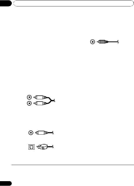
Standard RCA video cables
These cables are the most common type of video connection and are used to connect to the composite video terminals. The yellow plugs distinguish them from cables for audio.
Analog audio cables
Use stereo RCA phono cables to connect analog audio components. These cables are typically red and white, and you should connect the red plugs to R (right) terminals and white plugs to L (left) terminals.
Digital audio cables
Commercially available coaxial digital audio cables or optical cables should be used to connect digital components to this system.1
Coaxial digital audio cable
Optical cable
 Note
Note
1• When connecting optical cables, be careful when inserting the plug not to damage the shutter protecting the optical socket.
•When storing optical cable, coil loosely. The cable may be damaged if bent around sharp corners.
•You can also use a standard RCA video cable for coaxial digital connections.
16
En

Connecting up
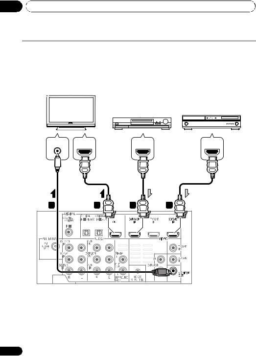
Connect your TV (For TV audio)
This will allow you to play the sound from the TV’s built-in tuner.
|
TV |
Select one |
|
AUDIO OUT |
DIGITAL OUT |
R ANALOG L |
OPTICAL |
1 |
2 |
 1
1
• Connect the analog audio outputs from your TV to the TV/SAT inputs on this system.
Use a stereo RCA phono cable.
•If your TV has a built-in digital decoder, you can also connect an optical digital audio output from your TV to the DIGITAL
OPTICAL IN 2 (AUX) input on this system. Use an optical cable for the connection.1
02
Nederlands Español Italiano Deutsch Français English
 Note
Note
1 In this case, you’ll need to tell the system which digital input you connected the TV to (see Choosing the input signal on page 36).
17
En
02 Connecting up
Connecting your TV and playback components
Connecting using HDMI
If you have an HDMI or DVI (with HDCP) equipped component (Blu-ray disc player, etc.), you can connect it to this system using a commercially available HDMI cable.
HDMI/DVI-compatible monitor or flat screen TV
HDMI/DVI-equipped
component
HDMI/DVI-compatible
Blu-ray disc player
VIDEO IN |
HDMI IN |
HDMI OUT |
HDMI OUT |
|
3 |
2 |
1 |
1 |
1 |
|
2 |
|
1 |
|
|
|
1Connect the HDMI output on your BD/ DVD player to the HDMI BD/DVD IN input on this system.
Use an HDMI cable for the connection.
2Connect the HDMI OUT on this system to an HDMI input on your TV.
3 Connect the MONITOR OUT on this system to the composite video input on your TV.
The OSD will not appear if you have connected using the HDMI output to your TV. Use composite connections for system setup.
Use a standard RCA video cable.
18
En

Connecting up |
02 |
Connecting your component with no HDMI terminal
This diagram shows connections of a TV and DVD player (or other playback component) with no HDMI terminal to the system.
DVD player, etc.
TV
|
Select one |
VIDEO OUT |
VIDEO IN |
|
DIGITAL OUT |
AUDIO OUT |
|
|
|
COAXIAL |
OPTICAL |
R ANALOG |
L |
|
|
|
2 |
1 |
3 |
|
1 |
|
|
|
1 |
|
|
|
|
1Connect the composite video output on your DVD player to the VIDEO BD/DVD input on this system.
Use a standard RCA video cable.
2Connect the audio output on your DVD player to the AUDIO BD/DVD IN inputs on this system.
Use a stereo RCA phono cable. If your component
has a digital output, you can also use an optical cable or coaxial cable for the connection.1
3 Connect the MONITOR OUT on this system to the composite video input on your TV.
Use a standard RCA video cable.
 Note
Note
1In this case, you’ll need to tell the system which digital input you connected the component to (see Choosing the input signal on page 36).
Nederlands Español Italiano Deutsch Français English
19
En
02 Connecting up
Connecting an HDD/DVD recorder, VCR and other video sources
This system has audio/video inputs and outputs suitable for connecting analog or digital video recorders, including VCRs and HDD/DVD recorders.
1 |
2 |
|
|
1 |
|
|
|
3 |
4 |
2 |
1 |
OPTICAL COAXIAL |
R ANALOG L |
R ANALOG |
L |
VIDEO IN |
HDMI OUT |
DIGITAL OUT |
AUDIO OUT |
AUDIO IN |
|
VIDEO OUT |
|
|
|
Select one |
|||
Select one |
|
|
|
||
|
|
|
|
||
DVR, VCR, LD player, etc.
1Connect the composite video output on your video component to the VIDEO DVR/VCR input on this system.
Use a standard RCA video cable.
•If the video component connected is equipped with an HDMI output, an HDMI cable may also be used for connection. In this case, use an HDMI cable to connect the TV as well.
2Connect the VIDEO DVR/VCR OUT on this system to the composite video input on your video component.
3Connect the audio output on your video component to the AUDIO DVR/VCR IN inputs on this system.
Use a stereo RCA phono cable. If your component has a digital output, you can also
use an optical cable or coaxial cable for the connection.1
4Connect a video inputs on the recorder to the VIDEO DVR/VCR output on this system.
Use a standard RCA video cable.
 Note
Note
1In this case, you’ll need to tell the system which digital input you connected the component to (see Choosing the input signal on page 36).
20
En
Connecting up
Connecting a satellite receiver or other digital set-top box
Satellite and cable receivers, and terrestrial digital TV tuners are all examples of so-called ‘set-top boxes’.
|
1 |
2 |
|
|
1 |
|
|
|
|
|
2 |
|
|
1 |
R ANALOG |
L |
COAXIAL |
OPTICAL |
HDMI OUT |
AUDIO OUT |
|
DIGITAL OUT |
VIDEO OUT |
|
|
Select one |
|||
Select one |
|
|||
|
|
|||
STB
1 Connect the composite video output on your set-top box to the VIDEO TV/SAT input on this system.
Use a standard RCA video cable.
•If the set-top box connected is equipped with an HDMI output, an HDMI cable may also be used for connection. In this case, use an HDMI cable to connect the TV as well.
2 Connect the audio output on your set-top box to the AUDIO TV/SAT IN inputs on this system.
Use a stereo RCA phono cable. If your component has a digital output, you can also use an optical cable or coaxial cable for the connection.1
02
Nederlands Español Italiano Deutsch Français English
 Note
Note
1 In this case, you’ll need to tell the system which digital input you connected the TV to (see Choosing the input signal on page 36).
21
En

02 Connecting up
Connecting other audio components
The number and kind of connections depends on the kind of component you’re connecting.1 Follow the steps below to connect a CD-R, MD, DAT, tape recorder or other audio component.
1 |
2 |
1 |
|
1 |
2 |
COAXIAL OPTICAL |
R ANALOG L |
R ANALOG L |
DIGITAL OUT |
AUDIO OUT |
AUDIO IN |
Select one
CD-R, MD, DAT, etc.
1 Connect the analog audio outputs of the component to a set of spare audio inputs on this system.
Use a stereo RCA phono cable. If your component has a digital output, connect this to a digital input on the system as shown.
2 If you’re connecting a recorder, connect the analog audio outputs to the analog audio inputs on the recorder.
The example shows an analog connection to the AUX OUT analog output jack using a stereo RCA phono cable.
 Note
Note
1 Note that you must connect digital components to analog audio jacks if you want to record to/from digital components (like an MD) to/from analog components.
22
En

Connecting up
Connecting to the front panel video terminal
Front video connections are accessed via the front panel using the VIDEO button on the remote control. There are standard audio/video jacks. Hook them up the same way you made the rear panel connections.
•Remove the panel cover when making connections to the front panel.
 VIDEO INPUT
iPod iPhone
USB |
VIDEO |
L AUDIO R |
VIDEO AUDIO
OUTPUT
Video camera, etc.
02
|
|
|
|
|
|
|
|
|
|
|
|
|
|
|
|
|
|
|
Connecting an iPod/iPhone |
English |
|||||||||||||||||
terminal that will allow you to control playback |
||||||||||||||||||
This system has a dedicated iPod /iPhone |
|
|||||||||||||||||
of audio content from your iPod/iPhone using |
|
|||||||||||||||||
the controls of this system. |
|
|
|
|
|
|
|
|
||||||||||
|
|
|
|
|
|
|
Français |
|||||||||||
• Switch the system into standby then use |
||||||||||||||||||
|
||||||||||||||||||
the USB cable (for iPod connection) to |
|
|||||||||||||||||
connect your iPod to the iPod/iPhone |
|
|||||||||||||||||
terminal on the front panel of this system. |
|
|||||||||||||||||
• Remove the panel cover when making |
|
|||||||||||||||||
connections to the front panel. |
|
|
|
|
Deutsch |
|||||||||||||
• The USB cable (for iPod connection) is not |
||||||||||||||||||
|
||||||||||||||||||
included with this system. For the cable |
|
|||||||||||||||||
connection, refer to also the operating |
|
|||||||||||||||||
instructions for iPod. |
|
|
|
|
|
|
|
|
||||||||||
• For instructions on playing the iPod, see |
Italiano |
|||||||||||||||||
Playing an iPod on page 37. |
|
|
|
|
||||||||||||||
|
|
|
|
|
||||||||||||||
|
|
|
|
|
|
|
|
iPod |
|
|
|
VIDEO INPUT |
|
|
|
|||
|
|
|
|
|
|
|
|
|
|
|
|
|||||||
|
|
|
|
|
|
|
|
|
|
|
|
|
|
|
|
|
||
|
|
|
|
|
|
|
iPhone |
|
|
|
|
|
|
|
|
|||
|
|
|
USB |
VIDEO |
L AUDIO R |
|
||||||||||||
Español |
||||||||||||||||||
|
|
|
|
|
|
|
|
|
|
|
|
|
|
|
|
|
||
|
|
|
|
|
|
|
|
|
|
|
|
|
|
|
|
|
||
|
|
|
|
|
|
|
|
|
|
|
|
|
|
|
|
|
|
|
|
|
|
|
|
|
|
|
|
|
|
|
|
|
|
|
|
|
|
USB cable (for |
|
|
|
|
|
|
|
|
|
MENU |
|
|
|
|
Nederlands |
|||
|
|
|
|
|
|
|
|
|
|
|||||||||
iPod connection) |
|
|
|
|
|
|
|
|
|
|
||||||||
|
|
|
|
|
|
|
|
|
|
|
|
|
|
|||||
|
|
|
|
|
|
|
|
|
|
|
|
|||||||
|
|
|
|
|
|
|
|
|
|
|
|
|
|
iPod |
|
|||
|
|
|
|
|
|
|
|
|
|
|
|
|
|
|
||||
Connecting using an optional cable
It is possible to watching photos and video content on your iPod using an optional iPod cable to connect your iPod to this system.
23
En

02Connecting up
•The optional iPod cable from Pioneer is sold separately under the part number ADE7129. Contact the Pioneer Customer Support division for more information on obtaining an optional iPod cable
 VIDEO INPUT
iPod iPhone
USB |
VIDEO |
L AUDIO R |
|
|
|
|
|
|
|
|
|
|
|
|
|
iPod cable (sold separately)
MENU
iPod
Connecting a USB device
It is possible to playback files using the USB interface on the front of this system.
• Switch the system into standby then connect your USB device to the USB terminal on the front panel of this system.
•Remove the panel cover when making connections to the front panel.
•For instructions on playing the USB device, see Playing a USB device on page 40.
 VIDEO INPUT
iPod iPhone
|
USB |
VIDEO |
L AUDIO R |
|
|
|
|
|
|
|
|
USB mass storage device
24
Connecting the FM antenna
Connect the FM wire antenna as shown below. To improve reception and sound quality, connect external antennas (see Connecting external antennas below).
• Push the FM antenna plug onto the center pin of the FM antenna socket.
For best results, extend the FM antenna fully and fix to a wall or door frame. Don’t drape loosely or leave coiled up.
Connecting external antennas
To improve FM reception connect an external FM antenna to the FM UNBAL 75 Ω.
75 Ω coaxial cable
J-shaped plug (not supplied)
En

Connecting up
Use the PRE OUT outputs to connect the surround back speakers
Connect the PRE OUT outputs of the system and additional amplifier to add a surround back speaker.
 1
1


 2
2


Surround back speakers
SBL |
SBR |
R ANALOG L
AUDIO IN
Surround back channel amplifier
•You can use the additional amplifier on the surround back channel pre-outs for a single speaker as well. In this case plug the amplifier into the left (L (Single)) terminal only.
Plugging in the system
Only plug in after you have connected all your components to this system including the speakers.
1Plug the supplied power cord into the AC IN socket on the back of the system.
2Plug the other end into a power outlet.
 CAUTION
•Handle the power cord by the plug part. Do not pull out the plug by tugging the cord, and never touch the power cord when your hands are wet, as this could cause a short circuit or electric shock. Do not place the unit, a piece of furniture, or other object on the power cord or pinch the cord in any other way. Never make a knot in the cord or tie it with other cables. The power cords should be routed so that they are not likely to be stepped on. A damaged power cord can cause a fire or give you an electric shock. Check the power cord once in a while. If you find it damaged, ask your nearest Pioneer authorized independent service company for a replacement.
•Do not use any power cord other than the one supplied with this unit.
•Do not use the supplied power cord for any purpose other than that described below.
•The system should be disconnected by removing the mains plug from the wall socket when not in regular use, e.g., when on vacation.
02
Nederlands Español Italiano Deutsch Français English
25
En

03 Controls and displays
Chapter 3
Controls and displays
Front panel
1 |
|
|
|
|
ST/MONO |
|
TUNE |
TUNE |
|
2 |
|
|
|
3 |
4 |
|
FUNCTION |
AUTO/DIRECT |
|
|
|
|
6 |
|
5 |
|
|
|
|
|
|
|
|
|
STANDBY/ON |
VOLUME |
|
||
7 |
|
|
|
8 |
|
|
|
VIDEO INPUT |
|
9 |
iPod |
|
|
10 |
iPhone |
|
|||
USB |
|
VIDEO |
L AUDIO |
R |
1 Front panel display
See Display on page 27 for details.
2Tuner control buttons
ST/MONO
Switches between auto stereo mode and mono reception mode (page 42).
TUNE +/–
Used to find radio frequencies (page 42).
3IR remote sensor
4Power indicator
5FUNCTION button
Selects an input source.
6 AUTO/DIRECT
Switches between Auto surround mode (Auto playback on page 44) and Stream Direct playback.
7 STANDBY/ON
Switches the system on or into standby.
8VOLUME +/–
Adjusts the volume.
9iPod/USB terminal
Use to connect your Apple iPod or USB mass storage device as an audio source (page 37 and 40).
10 AUDIO/VIDEO input
See Connecting to the front panel video terminal on page 23.
26
En

Controls and displays |
03 |
Display
1 |
2 |
3 |
4 |
5 |
6 |
7 |
8 |
9 |
10 |
11 |
12 |
13 |
12 |
14 |
1 PHASE
Lights when the Phase Control is switched on (page 46).
2 AUTO
Lights when the Auto Surround feature is switched on (see Auto playback on page 44).
3 ST
Lights when a stereo FM broadcast is being received in auto stereo mode.
4 TUNE
Lights when a normal broadcast channel is being received.
5 Sleep timer indicator
Lights when the system is in sleep mode (page 31).
6Tuner preset indicators
PRESET
Shows when a preset radio station is registered or called.
MEM
Blinks when a radio station is registered.
7PRESET Information or Input signal indicator
Shows the preset number of the tuner or the input signal type, etc.
8Character display
Displays various system information.
9DTS indicators
DTS
Lights when a source with DTS encoded audio signals is detected.
HD
Lights when a source with DTS-EXPRESS or DTS-HD encoded audio signals is detected.
ES
Lights when a source with DTS-ES encoded audio signals is detected.
96/24
Lights when a source with DTS 96/24 encoded audio signals is detected.
NEO:6
When one of the NEO:6 modes of the system is on, this lights to indicate NEO:6 processing (page 44).
10Dolby Digital indicators
2D
Lights when a Dolby Digital encoded signal is detected.
2D+
Lights when a source with Dolby Digital Plus encoded audio signals is detected.
2HD
Lights when a source with Dolby TrueHD encoded audio signals is detected.
Nederlands Español Italiano Deutsch Français English
27
En

03 Controls and displays
EX
Lights when a source with Dolby Digital EX encoded audio signals is detected.
2PLll(x)
Lights to indicate 2Pro Logic II / 2Pro Logic IIx decoding (see Listening in surround sound on page 44 for more on this).
11 ADV.S.
Lights when one of the Advanced Surround modes has been selected (see Using the Advanced surround effects on page 45 for more on this).
12SIGNAL SELECT indicators
DIGITAL
Lights when a digital audio signal is selected.
Blinks when a digital audio signal is not selected.
HDMI
Lights when an HDMI signal is selected. Blinks when an HDMI signal is not selected.
13UP MIX indicator
Lights when the UP MIX Setting is set to ON (page 48). Also, lights when DIMMER is set to off.
14 DIR.
Lights when the DIRECT or PURE DIRECT mode is switched on (page 46).
28
En

Controls and displays |
03 |
Remote control
SYSTEM |
|
SOURCE |
|
1 |
|
3 |
|
|
|
||
2 |
|
|
|
SYSTEM |
TV CONTROL |
5 |
|
4 |
INPUT |
|
|
|
|
||
|
|
CH |
|
6 |
|
|
|
|
DIMMER SIGNAL SEL |
VOL |
|
7 |
BD MENU |
|
8 |
|
|
||
9 |
|
|
|
10 |
|
|
12 |
11 |
ENTER |
|
|
|
|
|
|
|
|
MUTE |
14 |
13 |
|
|
|
|
|
|
|
|
|
DISPLAY |
16 |
|
|
|
|
15 |
|
CH |
|
|
|
|
|
|
|
CH |
|
|
ENTER |
|
17 |
|
|
|
|
SURROUND SYSTEM |
|
||
1 SYSTEM
Switches the system between standby and on.
2 INPUT SELECT
Use to select the input source.
3 SOURCE
Press to turn on/off other components connected to the system (see page 57 for more on this).
4
Switches the remote to control the system (used to select the white commands above the number buttons (S.RETRIEVER, etc)). Also use this button to set up surround sound (page 52) or Audio parameters (page 46).
5 TV CONTROL buttons
These buttons are dedicated to control the TV assigned to the TV button. Thus if you only have one TV to hook up to this system assign it to the TV button (see page 56 for more on this).
Use to turn on/off the power of the TV.
INPUT
Use to select the TV input signal.
CH +/–
Use to select channels.
VOL +/–
Use to adjust the volume on your TV.
6 MULTI CONTROL buttons
Press to select control of other components (see
Controlling the rest of your system on page 55).
7 DIMMER
Dims or brightens the display. The brightness can be controlled in four steps.
8 SIGNAL SEL
Use to select an input signal (page 36).
Press BD first to access:
BD MENU
Displays the disc menu of Blu-ray Discs.
Nederlands Español Italiano Deutsch Français English
29
En

03 Controls and displays
9Listening mode buttons
AUTO/DIRECT
Switches between Auto surround mode (Auto playback on page 44) and Stream Direct playback. Stream Direct playback bypasses the tone controls for the most accurate reproduction of a source (page 46).
STEREO/A.L.C.
Switches between stereo playback, Auto level control stereo mode (page 45) and Front Stage Surround Advance modes (page 45).
STANDARD
Press for Standard decoding and to switch between 2Pro Logic II options (page 44).
ADV SURR
Switches between the various surround modes (page 45).
10System Setup and Component control buttons
The following button controls can be accessed after you have selected the corresponding
MULTI CONTROL button (BD, TV, etc.).
Press 


 first to access:
AUDIO PARAMETER
Use to access the Audio options (page 46).
SETUP
Press to access the System Setup menu (page 52).
RETURN
Confirm and exit the current menu screen.
Press BD or DVR first to access:
TOP MENU
Displays the disc ‘top’ menu of a BD/DVD.
HOME MENU
Displays the HOME MENU screen.
RETURN
Confirm and exit the current menu screen.
MENU
Displays the TOOLS menu screen of Blu-ray Disc player.
Press TUNER first to access:
TUNER EDIT
Memorizes/names stations for recall (page 42 and 43).
ST/MONO
Switches between auto stereo mode and mono reception mode (page 42).
Press iPod USB first to access:
iPod CTRL
Switches between the iPod controls and the system controls (page 39).
11 (TUNE /, PRESET /),
ENTER
Use the arrow buttons when setting up your surround sound system (page 52). Also used to control BD/DVD menus/options.
Use the TUNE / buttons can be used to find radio frequencies (page 42) and the PRESET / buttons can be used to select preset radio stations (page 43).
12MASTER VOLUME +/–
Use to set the listening volume.
13Component control buttons
The main buttons ( , , etc.) are used to control a component after you have selected it using the input source buttons.
The controls above these buttons can be accessed after you have selected the corresponding input source button (for example BD, DVR or TV). These buttons also function as described below.
Press 


 first to access:
BASS –/+
Use to adjust Bass1
TRE –/+
Use to adjust Treble1
 Note
Note
1 The tone controls are disabled when the listening mode is set to DIRECT or PURE DIRECT.
30
En
Loading...