


PROJECTION MONITOR RECEIVER
SD-641HD5
Operating Instructions

FEATURES
Progressive Scan/HDTV READY
Dual System Component Input for NTSC/ Progressive
Connection to a DVD player with a component output terminal makes possible high-picture-quality display superior to that of S-VIDEO terminal connection. Also handles high resolution component input (1080i, 480p), which will function as an interface for high-quality images in future.
DUAL TUNER (SPLIT screen and SEARCH screen function)
Two TV tuners are provided, making it possible to split the screen vertically in two and display moving images simultaneously on them. In addition, the channel search function makes it possible to check, etc., on the program in the back. Its convenience will be limited only by your imagination.
Fully Illuminated Remote Control Unit
A fully illuminated universal remote control is used that makes it possible to operate other devices. Remote operations can thus be performed easily even in dark rooms and similar environments.
SURROUND 


 *
*
Natural front surround sound (SRS) with an expansive feel and natural sound similar to multi-channel surround sound (TruSurround) can be enjoyed.
Read and understand these 'Operating Instructions' before operating your Monitor. Follow the 'IMPORTANT SAFETY INSTRUCTIONSANDWARNINGS'sectionand all the warnings on the product.
Highly Detailed Image Display Technology
The tinted 0.52mm ultrafine-pitch screen, Hi Band Video Amplifier circuit, Progressive contour correction circuit and various other technologies for creating high picture quality make the display of highly detailed images possible.
Lens System for HDTV
Adoption of a lens system for high-resolution HDTV that faithfully reproduces HDTV 1080i signals allows highly colorsaturated images to be displayed at high resolution.
Whole Screen IR Receiver
The remote control sensor is installed behind the screen, allowing you to operate this monitor with the remote control unit in those installations where only the screen is revealed.
3D Y/C Separation Circuit
This three-dimensional Y/C separation circuit reproduces clearer picture quality.
Scan Velocity Modulation Circuit
Precise images from progressive scanning can be displayed in even greater detail, owing to the Scan Velocity Modulation (SVM) circuit.
Nine-Point Convergence System
Convergence adjustment of not only the center but 8 surrounding points makes it possible to display clear images with no color distortion around the screen.
*TruSurround, SRS and the SRS symbol are trademarks of SRSLabs,Inc.TruSurroundandSRSareincorporatedunder a license from SRS Labs, Inc. Patented in the U.S. and selected countries.
2
<ARB1526>
Thank you for purchasing this PIONEER Projection Monitor Receiver.
Please read theprecautionary instructionsenclosed with these operating instructions please do so before proceeding. After learning how to operate the Projection Monitor, be sure to keep this manual handy for future reference.
IMPORTANT NOTICE
The model number and the serial number of this Projection Monitor are located on the rear panel.
Please write the serial number on the enclosed warranty card and keep it in a safe place for future reference.
In this manual, we refer to the 'PROJECTION MONITOR RECEIVER', as the 'Projection Monitor' or the 'Monitor'.
Note on the SPLIT screen and SEARCH screen functions
The SPLIT screen and SEARCH screen functions provided in this monitor are intended for private viewing only.
Use of the above video processing functions for profitmaking purpose or for public viewing (clubs, hotels, etc.) without prior authorization from the transmitter and/or owner of the video program(s)maybeaninfringementofexistingcopyrightlaws.
WARNING:
TO REDUCE THE RISK OF THE FIRE OR ELECTRIC SHOCK, DO NOT EXPOSE THIS APPLIANCE TO WET LOCATIONS.
CAUTION:
TO PREVENT ELECTRIC SHOCK DO NOT USE THIS (POLARIZED) PLUG WITH AN EXTENSION CORD, RECEPTACLEOROTHEROUTLETUNLESSTHEBLADESCAN BE FULLY INSERTED TO PREVENT BLADE EXPOSURE.
ATTENTION:
POUR EVITER UNE DECHARGE ELECTRIQUE, NE PAS UTILISER CETTE PRISE (POLARISEE) AVEC UNE RALLONGE, UNE PRISE OU UNE AUTRE SORTIE A MOINS QUE LES LAMES PUISSENT ETRE COMPLETEMENT INTRODUITES ET NE SOIENT PAS EXPOSEES.
Note to CATV system installer:
This reminder is provided to call the CATV system installer's attention to Article 820-40 of NEC that provides guidelines for proper grounding and, in particular, specifies that the cable ground should be connected to the grounding system of the building, as close to the point of cable entry as practical.
Information to User
Alteration or modifications carried out without appropriate authorization may invalidate the user's right to operate the equipment.
IMPORTANT
CAUTION
RISK OF ELECTRIC SHOCK
DO NOT OPEN
The lightning flash with arrowhead symbol, within |
CAUTION: |
The exclamation point within an equilateral |
an equilateral triangle, is intended to alert the |
TO PREVENT THE RISK OF ELECTRIC SHOCK, DO |
triangle isintendedtoalerttheusertothepresence |
user to the presence of uninsulated "dangerous |
NOT REMOVE COVER (OR BACK). NO USER-SER- |
of important operating and maintenance |
voltage" within the product's enclosure that may |
VICEABLE PARTS INSIDE. REFER SERVICING TO |
(servicing) instructions in the literature |
be of sufficient magnitude to constitute a risk of |
QUALIFIED SERVICE PERSONNEL. |
accompanying the appliance. |
electric shock to persons. |
|
|
INTRODUCTION
NOTICE ON ADVERSE EFFECTS ON THE TV TUBE
When playing TV games, operating computers or displaying still pictures with your Monitor, be sure to keep in mind the following points;
1.Select the 'GAME' mode. (Refer to page 18 of the Operating Instructions)
2.Do not use your Monitor for more than two hours.
3.WatchnormalTVbroadcast'sforthreetimeslongerthanthetimeofplayingTVgames,operating
computers or displaying still pictures.
Still patterns can scar the Monitor causing performance damage to the CRT.
3
<ARB1526>
The following symbols are found in this manual and on the labels on the product. They alert the operators and service personnel of this equipment to potentially dangerous conditions.
 This symbol indicates an action that is prohibited.
 WARNING
This symbol refers to a hazard or unsafe practice which can result in severe personal injury or death.
 CAUTION
This symbol refers to a hazard or unsafe practice which can result in personal injury or property damage.
 WARNING
IMPORTANT SAFETY INSTRUCTIONS AND WARNINGS
∙Read all of these instructions.
∙Keep these instructions for later use.
∙Follow all warnings and instructions marked on the Monitor.
FOR YOUR PERSONAL SAFETY
1.This Monitor is equipped with a polarized alternating current line
plug (a plug having one blade wider than the other).
This plug will fit into the power outlet only one way. This is a safety feature.
If you are unable to insert the plug fully into the outlet, try reversing the plug. If the plug should still fail to fit, contact your electrician to replace your obsolete outlet. Do not defeat the safety purpose of the polarized plug.
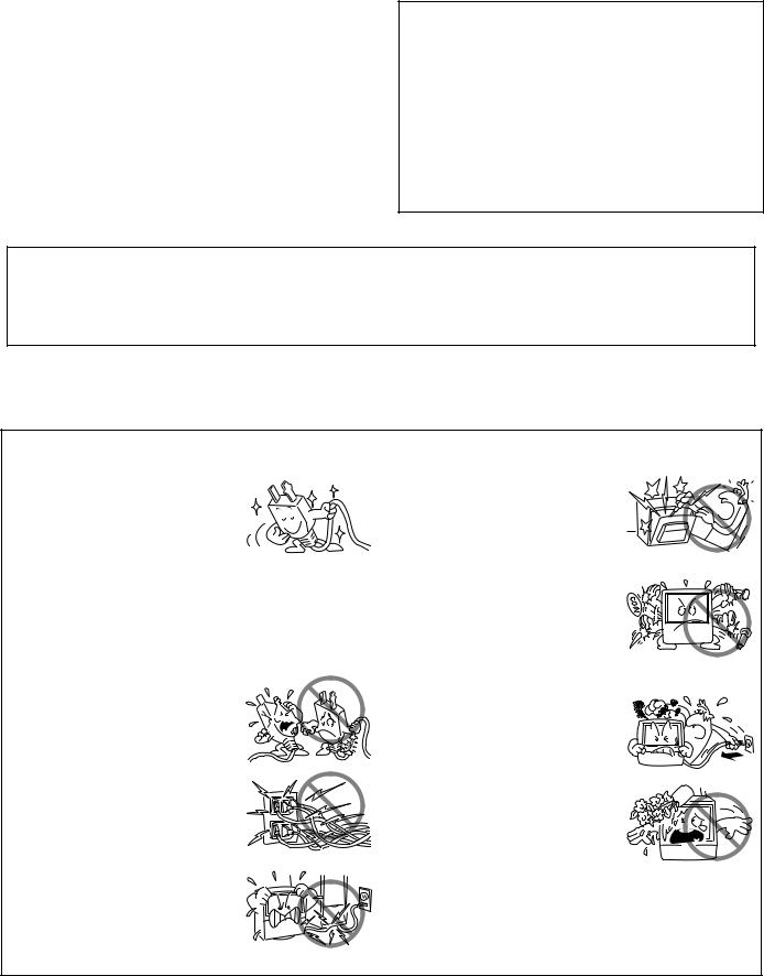
2. Ifthepowercordorplugbecomes damaged or frayed, unplug this Monitor from the wall outlet and refer to qualified service personnel for servicing.
3. Do not overload wall outlets and extension cords as this can result in fire or electrical shock.
4.Do not allow anything to rest on or roll over the power cord, and do not place the Monitor where
the power cord maybe subject to traffic or abuse. This may result in electrical or fire hazard.
5.Do not attempt to service this
Monitor yourself as opening or removingcoversmayexposeyou to dangerous voltage or other hazards. Refer all servicing to qualified personnel.
6. Neverpushtheobjectsofanykind into this Monitor through cabinet slots as they may touch dangerousvoltagepointsorshort out parts that could result in a fire orelectricshock.Neverspillliquid of any kind on the Monitor.
7. If the Monitor has been dropped orthecabinethasbeendamaged, unplug this Monitor from the wall outletandrefertoqualifiedservice personnel for servicing.
8.If liquid has been spilled into the Monitor,unplugtheMonitorfrom the wall outlet and refer servicing to qualified service personnel.
4
<ARB1526>

9.Do not subject your Monitor to impact of any kind. Be particularly careful not to damage the screen surface.
10.Unplug the Monitor from the wall outlet before cleaning. Do not use liquid cleaners or spray-type cleaners. Use a damp cloth for cleaning.
11-1. Do not place this Monitor on an unstable, uneven or an inclined location. The Monitor may overturn, causing serious injury (toaperson),andseriousdamage to the appliance.
11-2. Be careful when placing the Monitor on a cart to move it. Quick stops, excessive force, and uneven surfaces may cause the Monitor and cart to overturn.
PROTECTION AND LOCATION OF YOUR PROJECTION MONITOR RECEIVER
12.∙ Do not use the Monitor near water, for example, near a bathtub, washbowl, kitchen sink, orlaundrytub,inawetbasement, or near a swimming pool, etc.
∙Never expose the Monitor to rain water.
If the Monitor system has been exposed to rain or water, unplug the Monitor from the wall outlet and refer servicing to qualified service personnel.
13.Chooseaplacewherelight(artificial or sunlight) does not shine directly on the screen.
14.Avoid dusty places since the buildupofdustinsidetheMonitor's chassis may result in the malfunctioning, when high humidity persists.
15.∙ The Monitor has slots, or openings in the cabinet for ventilationpurposestoensurethe reliable operation of the Monitor, andtoprotectitfromoverheating. These openings must not be blocked or covered.
∙Never cover the slots or openings with cloth or other material.
∙Never block the bottom ventilation slots of the Monitor by placing it on a bed, sofa, rug, etc.
∙Never place the Monitor near or over a radiator or heat register.
∙Never place the Monitor in a builtin enclosure such as a bookcase, unless proper ventilation is provided.
16.If an outside antenna is connected through other equipment, be sure the antenna system is grounded so astoprovideprotectionagainstvoltagesurgesandbuiltup static charges. In the U. S. A., section 810 of the National Electrical Code, ANSI/NFPA 70, provides information on proper grounding of the mast and supporting structure, grounding of the lead-in wire to an antenna-discharge unit, size of grounding conductors, location of antenna-discharge unit, connection to grounding electrode, and requirements for the grounding electrode.
|
NEC-NATIONAL |
|
|
ELECTRICAL CODE |
|
|
ANTENNA |
|
|
LEAD IN WIRE |
|
|
GROUND |
|
|
CLAMP |
|
|
ANTENNA |
|
|
DISCHARGE UNIT |
|
|
(NEC SECTION 810-20) |
|
ELECTRIC |
|
|
SERVICE |
GROUNDING CONDUCTORS |
|
EQUIPMENT |
||
(NEC SECTION 810-21) |
||
|
||
|
GROUNDING CLAMPS |
|
FIG. A |
POWER SERVICE GROUNDING |
|
|
||
|
ELECTRODE SYSTEM |
|
|
(NEC ART 250, PART H) |
EXAMPLE OF ANTENNA GROUNDING IN NATIONALELECTRICALCODEINSTRUCTIONS
5
INTRODUCTION
<ARB1526>
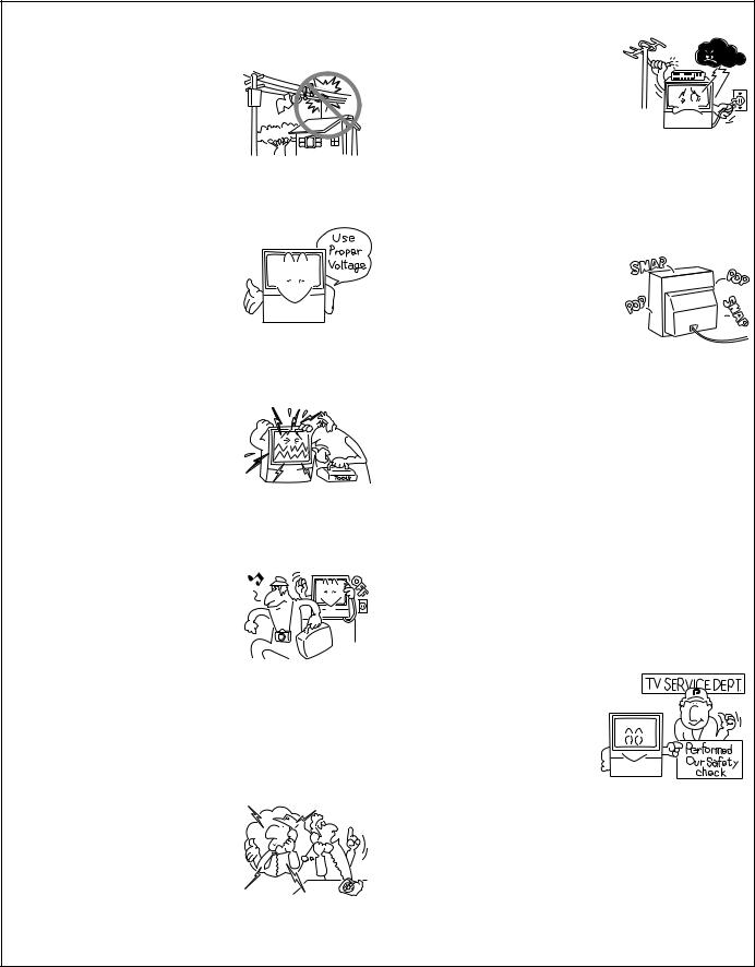
17.An outdoor antenna system should not be located in the vicinity of overhead power lines/ electric lights or power circuits, or where it can fall onto such power lines or circuits. When installing an outdoor antenna system, extreme care should be taken to keep it from touching such power lines or circuits as contact with them might be fatal.
18.For added protection during a lightning storm, or when it is left unattended and unused for long periods of time, unplug the Monitor from the wall outlet and disconnect the antenna. This will prevent damage due to lightning and power-line surges.
OPERATION OF YOUR PROJECTION MONITOR RECEIVER
19.The Monitor should be operated only from the type of power source indicated on the marking
label.Ifyouarenotsureofthetype of power supply at your home, consultyourdealerorlocalpower company.
20.Ifyouareunabletorestorenormal operation by following the detailed procedure in your operating instructions, unplug it
from the wall outlet and refer to  qualified service personnel for servicing. Do not adjust other
  controls than those described in
  this manual. Improper adjustments may result in damage and will often require extensive work by a qualified technician to restore the Monitor
to normal operation.
21. If your Monitor is to remain unused for a period of time, for instance, when you go on a holiday, turn the Monitor 'off' and unplug it from the wall outlet.
IF THE PROJECTION MONITOR RECEIVER DOES NOT OPERATE PROPERLY
22.Ifyouareunabletorestorenormal operation by following the detailed procedure in your
operating instructions, do not attempt any further adjustment. Unplug the Monitor and call your dealer or service technician.
23.Whenever the Monitor is damaged or fails, or there is a distinct change in performance, unplug the Monitor and have it checked by a professional service technician.
24.It is normal for some Monitor to make occasional snapping or
popping sounds, particularly when being turned on or off. If the snapping or popping is continuous or frequent, unplug the Monitor and consult your dealer or service technician.
FOR SERVICING AND MODIFICATION
25.Do not use attachments not recommended by the Monitor's manufacturer as they may result in the risk of fire, electrical shock or injury to persons.
26.When replacement parts are required, be sure the service technicianusesreplacementparts specifiedbythemanufacturerthat have the same characteristics as the original part. Unauthorized substitutions may result in fire, electrical shock, or injury.
27.Upon completion of any service or repairs to the Monitor, ask the service technician to perform routinesafetycheckstodetermine
that the Monitor is in a safe operating condition.
6
<ARB1526>

CONTENTS
INTRODUCTION |
|
INSTALLING THE MONITOR ..................................................... |
8 |
BEFORE USE ........................................................................... |
10 |
TO WATCH TV |
|
TO WATCH TV ......................................................................... |
12 |
Viewing two screens (SPLIT screen) ................................................ |
14 |
Making notes on program content (FREEZE screen) ........................ |
14 |
Searching for a program on a different channel (SEARCH screen) .. |
15 |
ADJUSTMENTS AND SETTINGS |
|
CHECKING THE MENU............................................................ |
16 |
PICTURE ADJUSTMENTS ....................................................... |
18 |
Recall the desired settings ........................................................... |
18 |
Storing the set picture quality in memory ........................................ |
19 |
To adjust the picture quality ......................................................... |
20 |
Other picture quality adjustments ............................................... |
21 |
SOUND ADJUSTMENTS ........................................................ |
25 |
Watching stereo and bilingual programs.................................... |
25 |
To adjust the sound quality .......................................................... |
26 |
To select the desired surround mode .......................................... |
27 |
TO CHANGE SCREEN SIZE ..................................................... |
28 |
Setting screen mode ..................................................................... |
28 |
To switch the screen size automatically ........................................... |
29 |
To adjust the screen position ........................................................... |
31 |
CLOSED CAPTION DECODE FUNCTION ................................. |
32 |
CONNECTION |
|
CONNECTING THE ANTENNA ................................................ |
33 |
CONNECTING OTHER EQUIPMENT ........................................ |
34 |
REMOTE CONTROL UNIT |
|
REMOTE CODE SET UP........................................................... |
41 |
Calling other manufacturers' remote control signals preset ..... |
41 |
To learn remote control signals ................................................... |
43 |
REMOTE CONTROL UNIT FUNCTIONS .................................. |
45 |
SETTING AT INSTALLATION |
|
To automatically preset channels in your area ........................... |
52 |
To add or delete preset channels ................................................. |
54 |
Favorite channel set up ................................................................ |
57 |
The color-convergence deviation by earth magnetism ............. |
59 |
To adjust the picture quality automatically |
|
to room brightness (DPO) ............................................................ |
62 |
To select the desired language on the menu screen .................. |
63 |
OTHERS |
|
FRONT PANEL FUNCTIONS .................................................... |
64 |
MENU INDEX .......................................................................... |
66 |
TROUBLESHOOTING .............................................................. |
72 |
SPECIFICATIONS ..................................................................... |
74 |
|
7 |
<ARB1526>
INSTALLING THE MONITOR
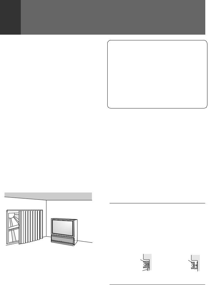
INSTALLATION PRECAUTIONS:
•Keep away from magnetic fields
The picture may be distorted if strong magnetic fields are nearby. External speakers should be set at least 2 feet (60cm) away from the Projection Monitor. Electric fans and other motor driven appliances and toys may also be sources of magnetism.
•Bright light or direct sunlight will dull the picture. Position the Projection Monitor so that the screen faces away from windows.
•While the Projection Monitor is operating, it is cooled by airflow through ventilation holes in the rear and bottom. Therefore, avoid placing it in a location where the cooling airflow is hindered (e. g. against a wall).
•Avoid places subject to extremely high temperatures or humidity, or to temperatures of 41°F (5°C) or lower. Also avoid dusty places.
•If setting the Projection Monitor on a floor made of soft material, make sure that the floor will not damaged by the weight of the Projection Monitor.
•Do not put the Projection Monitor on a surface that is tilted, unsteady or prone to shake or vibrate. A shaky or slanted platform is dangerous.
•Cover shiny surfaces (floor and walls) with non reflective materials (carpet, rugs, wallpaper, etc.).
OPERATING PRECAUTIONS
Optimum viewing distance
10 to 23 feet is the range recommended for viewing comfort.
Adjust room illumination
Excessively bright or dim lighting may strain your eyes. Draw the curtains if necessary to shut out direct sunlight.
Condensation and picture blurring
•If the room temperature suddenly rises (or if the Projection Monitor is moved from a cool place to a hot place), condensation may form on the lenses resulting in picture distortion or color fading. If this occurs, simply wait a while (with the power switch ON) and the condensation will disappear.
•A gradual change in temperature can prevent condensation from forming.
CARE OF YOUR PROJECTION MONITOR
DO NOT:
•Donotusestrongcleansers,solvents,polishes,orchemically treated cloths to clean the screen or cabinet.
•Do not touch or scratch the screen.
•Do not fasten or place rubber or vinyl items on the Monitor.
•Do not stick adhesive tape onto the Monitor.
•Do not put any object on the Monitor.
DO:
•Use a soft cloth to dust the screen and cabinet.
•Handle the screen with care to avoid scratches or damages.
•Ask your dealer or a Pioneer authorized service center to clean the interior of the monitor in your area if the picture brightness is too low even with the max. level. This may be caused by dust buildup inside.
HOW TO ATTACH THE PROVIDED PROTECTIVE SCREEN
WE RECOMMEND ATTACHING THE PROTECTIVE SCREEN BEFORE USING THE MONITOR.
To improve the image reproduction characteristics of the monitor and to protect the screen from damage or dust, attach the provided protective screen to the screen frame of the monitor following the given procedure.
If you decide not to install the protective screen, attach the upper and lower panel frames as indicated and attach the corresponding trim. If the protective screen is not being used, store it on a flat surface. Do notleanitagainstawall,asitwillbecomewarped.Keepthemicroform cushion and cardboard container for screen storage. Please note that the monitor does not use the side frame covers when the protective screen is not attached to the monitor.
PARTS INCLUDED FOR PROTECTIVE SCREEN INSTALLATION:
1 |
PROTECTIVE SCREEN WITH EDGE GUARDS |
|
2 |
PANEL FRAMES |
(MOUNTS) |
2 |
SIDE FRAME COVER |
(TRIM) |
2 |
FRAME COVER |
(TRIM) |
10 |
PANEL FRAME ATTACHING SCREWS |
(FASTENERS) |
|
|
|
HOW TO ATTACH UPPER AND LOWER TRIM ONLY
Attach upper and lower panel frames as indicated then follow step 5 on HOW TO ATTACH SCREEN.
<SIDE VIEW> |
<SIDE VIEW> |
Panel frame |
Panel frame |
Protective screen |
|
When the protective screen |
When the protective screen |
is attached. |
is not attached. |
8
<ARB1526>
CAUTION: BEFORE ATTACHING THE PROTECTIVE SCREEN
•Do not handle the screen by yourself. (It weights 12.4 lbs/6.0 kg) Have someone assist you when attaching or carrying the screen to prevent any accidents.
•Use a large-sized Phillips-head screwdriver for screwing and unscrewing fasteners.
•Handle the screen with care to avoid injury and to avoid leaving fingerprints on the screen surface.
•Carefully peel the vinyl covering from the front and back of the protective screen. Inspect the screen and brush off any plastic shavings or particles from the screen surface.
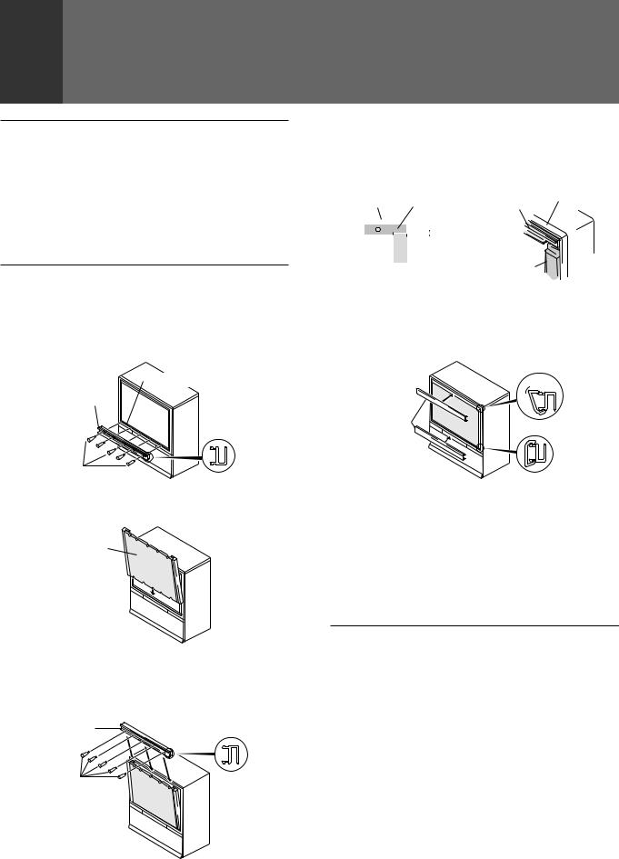
HOW TO ATTACH THE PROTECTIVE SCREEN
1.Attach the lower panel frame to the monitor using five screws starting with the center screw.
Do not overtighten the screws.
Overtightened screws may cause the acrylic protective panel to warp.
Screen frame
Panel frame
Side view
2.Insert the protective screen into the lower panel frame making sure the labeled side is to be front.
Protective screen
Label 
3.While holding the screen in place, attach the upper panel frame to the screen and fasten five screws starting with the center screw.
Do not overtighten the screws.
Overtightened screws may cause the acrylic protective panel to warp.
Panel frame
 Side view
INSTALLING THE MONITOR
4. Attach side frame covers: |
|
|
|
|||||||||
|
|
|
||||||||||
1) Peel off adhesive strip from rear side of the frame cover. |
|
|||||||||||
2) Attach side frame cover along the aluminium edge guards |
INTRODUCTION |
|||||||||||
leaving a space of approximately 0 to 1/32 in. (0 to 1 mm) |
||||||||||||
|
||||||||||||
from the upper panel frame. |
|
|
|
|||||||||
|
|
|
|
Upper panel |
Screen frame |
|
||||||
Screen frame frame |
Upper panel |
|
||||||||||
|
|
|
||||||||||
|
|
|
|
|
|
|
|
frame |
|
|
|
|
|
|
|
|
|
|
|
|
0 to 1 mm |
|
|
|
|
|
|
|
|
|
|
|
|
|
|
|
||
|
|
|
|
|
|
|
|
(0 to 1/32 in.) |
|
|
|
|
|
|
|
|
|
|
|
|
Side frame |
|
|
|
|
|
|
|
|
|
|
|
|
|
|
|
||
|
|
|
|
|
|
|
|
|
|
|
||
Side frame cover |
|
|
|
|||||||||
cover |
|
|
|
|||||||||
5.Attach the remaining frame covers to the upper and lower panel frames: first, insert the edge of the frame cover into the outer groove of the panel frame, then starting at one end, push the inner part of the frame cover over the inner edge of the panel frame snapping it into place.
Upper frame cover
Remove

 Attach
Frame cover
Lower frame cover
HOW TO REMOVE THE PROTECTIVE SCREEN
1)First, remove the frame covers only from the upper and lower panelframes.Caremustbetakentoavoidscratchingtheprotective screen or frame covers.
2)Remove the screws from the upper panel frame and remove the upper panel frame.
3)Remove the protective screen from the lower panel frame and remove the lower panel frame. Reattach panel frames and frame covers as indicated in HOW TO ATTACH UPPER AND LOWER TRIM ONLY.
NOTES FOR CARE AND CLEANING OF SCREEN:
•Do not hit or throw anything onto the protective screen, as a damaged protective screen may cause injury.
•If the protective screen surface is dirty, wipe it with a cloth dipped in warm water with mild detergent and then wrung out. Wipe it dry with a soft, dry cloth.
•Never use paint thinner or other cleaners to clean the protective screen as they may contain harmful chemicals that will damage the finish of the screen.
9
<ARB1526>
BEFORE USE
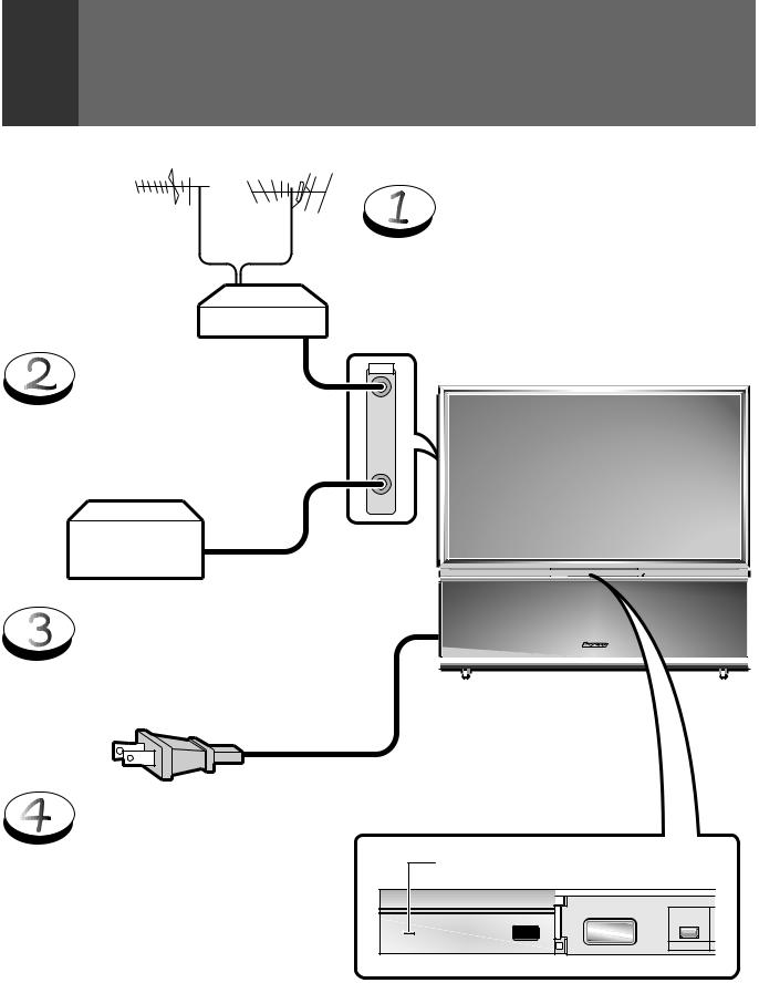
Before you watch the TV, perform the following procedure.
UHF VHF
Mixer
Connect the CATV converter to the ANTENNA B terminal. (See page 33)
CATV converter
ConnectthecablesoftheVHFantenna and UHF antenna to the ANTENNA A terminal. (See page 33)
ANTENNA |
/CABLE |
A |
B |
Û¿>¯,ÙÛB ¿.??ÙÛ
Connectthepowercordtothe
AC wall socket.
Turn on the MAIN POWER switch.
When the MAIN POWER is on, the STANDBY/ON indicator lights up in red. In this state, the POWER STANDBY/ON button or the POWER button of the remote control unit can be used to turn on and off the Monitor.
Red indicator
|
|
STANDBY/ON |
|
|
MAIN |
|
|
POWER |
STANDBY/ON |
DPO |
POWER |
10
<ARB1526>
BEFORE USE
Inserting batteries into the remote control unit
1.
2. |
Two DURACELL® 'AA' MN1500 1.5V |
|
ALKALINE dry cell batteries |
||
|
 CAUTION
Incorrectuseofbatteriesmayleadtoleakageorrupture. Always be sure to follow these instructions.
A.
Never mix new and used batteries.
B.
Batteries of the same size may have different voltages depending on their type. Do not mix different types of batteries.
9

 (
(
(
9
INTRODUCTION
Remote control operation range
30˚
30˚
23 feet (7m)
•Furniture and other obstacles may block the infrared light beamsothatitcannotreachthesensorbehindtheProjection Monitor's screen.
•Performance of the remote control unit is adversely affected by strong fluorescent light. Keep such lights away from the screen in particular.
Battery replacement
Replace the batteries when any of the following phenomena is observed.
•The transmitting LED does not blink even when the TV POWER button is pressed.
•The remote control operation range has reduced.
When replacing the batteries, prepare new batteries before removing the old batteries.
Be sure to close the battery case cover after battery replacement.
NOTE:
•Even when batteries are removed, learned commands remain in memory for about 15 minutes.
•If you remove the batteries, and press a button, the memory is erased in a few seconds.
11
<ARB1526>
TO WATCH TV
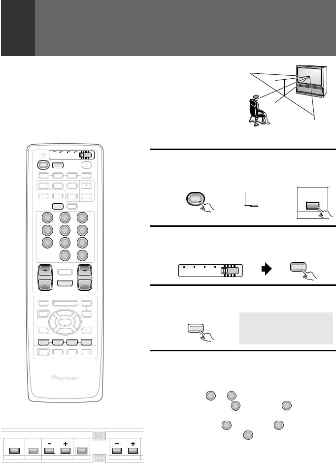
Best Horizontal and Vertical Viewing Angle
∙The optimum viewing angle is 140˚ in horizontal and 45˚ in vertical.
∙Watch from at least 10 feet (3m) away from the screen (optimum viewing distance is 10 to 23 feet).
45˚
140˚
Remote control unit
TV |
CBL VCR DVD |
|
TV |
/SAT |
/LD |
POWER TV
INPUT
1 |
2 |
3 |
4 |
SPLIT |
SEARCH |
SELECT |
|
SCREEN |
|
SUB CH |
|
MODE |
AUTO |
FREEZE |
|
ANT DISPLAY
1 2 3
4 5 6
7 8 9
CH
0 ENTER
¢ CH
RETURN
CH |
VOL |
4 |
MUTING |
EDIT/ |
DVD |
Turn on the MAIN POWER switch.
1 Turn on the POWER.
The STANDBY/ON indicator lights up in green.
Remote control unit |
Control panel of the monitor |
|
TV |
Green indicator |
|
POWER |
|
STANDBY/ON |
|
STANDBY/ON |
POWER |
2 SetthemodeswitchtoTV/DTVandthen
press the TV button.
Remote control unit
TV
TV CBL VCR DVD /SAT /LD
3 Select antenna A or B.
LEARN |
MENU |
MENU |
SOURCE |
|
SAT |
Check the input signals at the ANTENNA A and B terminals.
POWER |
5 |
GUIDE |
2 |
ENTERSET/ |
3 |
|
FAVORITE CH |
VCR REC |
|
1 |
7 |
3 |
¡ |
Remote control unit
A N T . A C H 2
ANT |
RECEIVER
POWER |
INPUT |
VOL |
VOL |
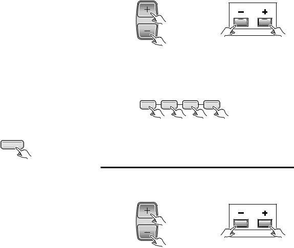
4 Select a channel.
There are three methods for this.
|
|
|
|
|
|
1 Select by pressing the number button |
|
||
|
|
PROJECTION MONITOR RECEIVER |
Î |
|
(Example) |
|
|
|
|
|
|
REMOTE CONTROL UNIT |
|
|
|
|
|
||
|
|
|
|
|
|
|
CH |
|
|
|
|
|
|
|
|
Channel 5 ..... 5 → ENTER |
|
|
|
|
|
|
|
|
|
(Or press |
0 |
and then press |
5 within 2 seconds |
Control panel of the monitor |
|
|
|
of during so.) |
|
|
|||
|
|
|
Channel 12 ... Press 1 |
and then press 2 |
within 2 seconds of |
||||
|
|
|
|
|
|
||||
|
|
|
|
|
|
during so. → |
CH |
|
|
|
|
|
|
|
|
ENTER |
|
||
STANDBY/ON |
|
|
|
|
|
|
|
|
|
|
|
|
|
|
|
• After pressing a number button, even if you do not press the CH |
|||
POWER |
INPUT |
CHANNEL |
RETURN |
VOLUME |
ENTER button, the channel will be switched to the one selected within |
||||
SELECTOR |
|||||||||
|
|
|
|
|
|
2 seconds. |
|
|
|
12 |
|
|
|
|
|
• Depending on the channel, this switch may occur immediately after |
|||
|
|
|
|
|
the number button is pressed. |
|
|||
<ARB1526>
|
|
|
|
|
|
|
|
|
|
|
|
|
|
|
|
|
|
|
TO WATCH TV |
|
|
|
||||
|
|
|
|
|
|
|
|
|
|
|
|
|
|
|
|
|
|
|
|
|
|
|
|
|
|
|
|
VHF L |
|
MID |
VHF H |
|
SUPER |
|
|
|
|
HYPER |
|
|
|
|
UHF |
|
|
|
|||||||
TV |
2-6 |
|
|
|
|
7-13 |
|
|
|
|
|
|
|
|
|
|
|
|
|
|
14-69 |
|
|
|
||
|
|
|
|
|
|
|
|
|
|
|
|
|
|
|
|
|
||||||||||
|
|
A-5(95) |
A(14) |
|
J(23) Q(30) |
W+1(37) |
W+11(47) |
W+21(57) |
W+31(67) |
W+41(77) |
W+51(87) |
W+61(102) |
W+71(112) |
W+81(122) |
|
|
|
|
|
|
||||||
|
|
A-4(96) |
B(15) |
|
K(24) R(31) |
W+2(38) |
W+12(48) |
W+22(58) |
W+32(68) |
W+42(78) |
W+52(88) |
W+62(103) |
W+72(113) |
W+82(123) |
|
|
|
|
|
|
||||||
|
|
|
|
|
|
|
|
|
|
|
|
|
|
|
|
|
|
|
|
|
|
|
|
|
|
|
|
2-6 |
A-3(97) |
C(16) |
|
L(25) S(32) |
W+3(39) |
W+13(49) |
W+23(59) |
W+33(69) |
W+43(79) |
W+53(89) |
W+63(104) |
W+73(114) |
W+83(124) |
|
|
|
|
|
|
||||||
|
|
|
|
|
|
|
TO |
|||||||||||||||||||
|
|
|
|
|
|
|
|
|
|
|
|
|
|
|
|
|
|
|
|
|
|
|
|
|
||
|
A-2(98) |
D(17) |
|
M(26) T(33) |
W+4(40) |
W+14(50) |
W+24(60) |
W+34(70) |
W+44(80) |
W+54(90) |
W+64(105) |
W+74(115) |
W+84(125) |
|
|
|
|
|
||||||||
|
(STD) |
|
|
|
|
|
|
|
|
|
|
|
|
|
|
|
|
|
|
|
|
|
|
|
||
CATV |
A-1(99) |
E(18) |
7-13 |
N(27) U(34) |
W+5(41) |
W+15(51) |
W+25(61) |
W+35(71) |
W+45(81) |
W+55(91) |
W+65(106) |
W+75(116) |
|
|
|
|
||||||||||
(IRC) |
|
|
|
|
|
|
|
|
|
|
|
|
|
|
|
|
|
|
|
|
|
|
|
WATCH |
||
|
|
F(19) |
O(28) V(35) |
W+6(42) |
W+16(52) |
W+26(62) |
W+36(72) |
W+46(82) |
W+56(92) |
W+66(107) |
W+76(117) |
|
|
|
|
|
|
|||||||||
|
|
|
|
|
|
|
|
|
|
|||||||||||||||||
|
|
|
|
|
|
|
|
|
|
|
|
|
|
|
|
|
|
|
|
|
|
|
|
|
|
|
|
1-6 |
|
|
G(20) |
|
P(29) W(36) |
W+7(43) |
W+17(53) |
W+27(63) |
W+37(73) |
W+47(83) |
W+57(93) |
W+67(108) |
W+77(118) |
|
|
|
|
|
|
|
|||||
|
|
|
|
|
|
|
|
|
|
|
|
|
|
|
|
|
|
|
|
|
|
|
|
|
|
|
|
|
|
H(21) |
|
|
|
|
W+8(44) |
W+18(54) |
W+28(64) |
W+38(74) |
W+48(84) |
W+58(94) |
W+68(109) |
W+78(119) |
|
|
|
|
|
|
|
||||
|
(HRC) |
|
|
|
|
|
|
|
|
|
|
|
|
|
||||||||||||
|
|
|
|
|
|
|
|
|
|
|
|
|
|
|
|
|
|
|
|
|
|
|
|
|
|
|
|
|
|
I (22) |
|
|
|
|
W+9(45) |
W+19(55) |
W+29(65) |
W+39(75) |
W+49(85) |
W+59(100) |
W+69(110) |
W+79(120) |
|
|
|
|
|
|
|
||||
|
|
|
|
|
|
|
|
|
|
|
|
|
|
|
||||||||||||
|
|
|
|
|
|
|
|
|
|
|
|
|
|
|
|
|
|
|
|
|
|
|
|
|
|
TV |
|
|
|
|
|
|
|
|
|
|
W+10(46) |
W+20(56) |
W+30(66) |
W+40(76) |
W+50(86) |
W+60(101) |
W+70(111) |
W+80(121) |
|
|
|
|
|
|
|||
CABLE (CATV) CHANNEL |
|
|
2 Select using the TV CH+/– button |
|
|
|||||||||||||||||||||
|
|
|
|
|
||||||||||||||||||||||
ASSIGNMENT TABLE |
The channels will switch according to the order set by channel |
|
preset (See page 52). |
||
|
In the cable tuning mode, channels can only be assigned to numbers 01 to 125. The specific channel number assignments and the corresponding alphabet designation are shown at the bottom left of the channel table.
For example: Channel number '14' corresponds to midband cable channel 'A'.
NOTE:
Cable (CATV) services can vary according to area. The channel number assignments shown in the channel table may not correspond with the channel numbers used by your local cable company. Direct tuning to cable channels without using the cable company converter 'or preselector' will depend on the specific channels in use by the cable company. Direct tuning to cable channels is limited to unencoded (unscrambled) channels only. Check with your local cable company for compatibility requirements.
To turn off the sound
Press the MUTING button.
MUTING |
Remote control unit |
Control panel of the monitor |
CH |
|
|
CHANNEL |
3 Select using the FAVORITE CH button
Select your desired channel from the 4 in the memory of each button: blue, green, red and yellow.
Remote control unit
FAVORITE CH
1 7 3 ¡
•Each time the button is pressed, the channel will be changed in order of the 4 channels in that button's memory.
•The desired channels can be set. (See page 57.)
•When you select a channel using the FAVORITE CH button, step 3 (Select antenna A or B) is not necessary.
When mute is turned on, a volume indicator will |
5 Adjust the volume. |
|
appear in red on the screen (and will disappear in |
|
|
a few seconds). |
|
|
If the MUTING button is pressed while a closed |
Remote control unit |
Control panel of the monitor |
caption signal is being received, CC/TEXT will be |
||
displayed. |
|
|
Press MUTING again to return to the previous |
|
|
volume level. |
VOL |
|
|
|
|
Auto power off function |
|
VOLUME |
If the monitor is receiving no input signals after the power has been turned ON, the power for it
will turn off (go on standby) after some time has
passed.
13
<ARB1526>
TO WATCH TV
TV |
CBL VCR DVD |
|
TV |
/SAT |
/LD |
POWER TV
INPUT
VIEWING TWO SCREENS (SPLIT screen)
Thescreencanbesplitvertically,makingitpossibletoviewdifferentimages on the left and right.
Press the SPLIT button.
1 |
2 |
3 |
4 |
SPLIT |
SEARCH |
SELECT |
SCREEN |
SUB CH |
|
MODE |
AUTO |
FREEZE |
A N T . A 3 6 |
A N T . A 3 6 |
A N T . B 2 5 |
SPLIT |
ANT DISPLAY
1 2 3
4 5 6
7 8 9
|
0 |
CH |
|
ENTER |
|
¢ CH |
|
|
|
RETURN |
|
CH |
|
VOL |
|
MUTING |
|
4 |
|
|
EDIT/ |
|
DVD |
LEARN |
MENU |
MENU |
SOURCE |
5 |
SAT |
POWER |
GUIDE |
|
2 |
ENTERSET/ |
3 |
FAVORITE CH  VCR REC
1 7 3 ¡
RECEIVER
POWER |
INPUT |
VOL |
VOL |
(Main picture) (Sub picture)
∙ The screen on which is displayed is the main picture, and the other screen is the sub-picture. Sound will be output for the main picture.
∙Regular operations can be performed on the main picture.
∙When the SUB CH +,- buttons are pressed, the channel for the subpicture will be changed.
∙ When the SELECT button is pressed, the screen.
∙The MONITOR OUTPUT terminal outputs the main picture signal.
∙Pressing the SPLIT button again will restore the original screen.
MAKING NOTES ON PROGRAM CONTENT (FREEZE screen)
The screen can be frozen, such as for taking down a recipe from a cooking program or an address for entering a quiz or the like.
NOTES:
•The same image cannot be viewed as both the main picture and the sub-picture.
•Pressing the MENU button in SPLIT or FREEZE screen mode restores the screen display to normal and displays the menu on screen.
•These functions cannot be used when INPUT 1 or INPUT 2 is receiving a 1080i or 480p component signal (or the signals might not be received or noise might be generated).
•Continuous operation for extended periods in SPLIT or FREEZE screen mode may burn out the screen.
We thus recommend that these modes only be used in conjunction with the normal screen mode.
Press the FREEZE button.
A N T . A 3 6
FREEZE |
|
A N T . A 3 6 |
Moving screen |
Still screen |
|
|
∙This function is operable only with the normal screen.
∙Pressing the FREEZE button again will restore the original screen.
14
<ARB1526>
TO WATCH TV
SEARCHING FOR A PROGRAM ON A
DIFFERENT CHANNEL (SEARCH screen)
Thescreenontherightsidecanbemadeintonineorthreedifferentscreens, making it possible to search for programs or enjoy multiple images.
|
TV CBL VCR DVD |
|
|
TV |
/SAT |
/LD |
|
POWER |
TV |
|
Press the SEARCH button. |
|
INPUT |
|
|
1 |
2 |
3 |
4 |
SPLIT |
SEARCH |
SELECT |
SCREEN |
SEARCH |
|
SUB CH |
||
MODE |
AUTO |
FREEZE |
ANT |
DISPLAY |
|
1 |
2 |
3 |
4 |
5 |
6 |
7 |
8 |
9 |
|
0 |
CH |
|
ENTER |
|
¢ CH |
|
|
RETURN |
|
|
CH |
|
VOL |
MUTING |
|
|
4 |
|
|
EDIT/ |
|
DVD |
LEARN |
MENU |
MENU |
SOURCE |
5 |
SAT |
POWER |
GUIDE |
|
2 |
ENTERSET/ |
3 |
FAVORITE CH  VCR REC
1 7 3 ¡
RECEIVER
POWER |
INPUT |
VOL |
VOL |
•Pressing the MENU button in SEARCH screen mode restores the screen display to normal and displays the menu on screen.
•These functions cannot be used when INPUT 1 or
INPUT 2 is receiving a 1080i or 480p component signal (or the signals might not be received or noise might be generated).
•Continuous operation for extended periods in SEARCH screen mode may burn out the screen. We thus recommend that these modes only be used in conjunction with the normal screen mode.
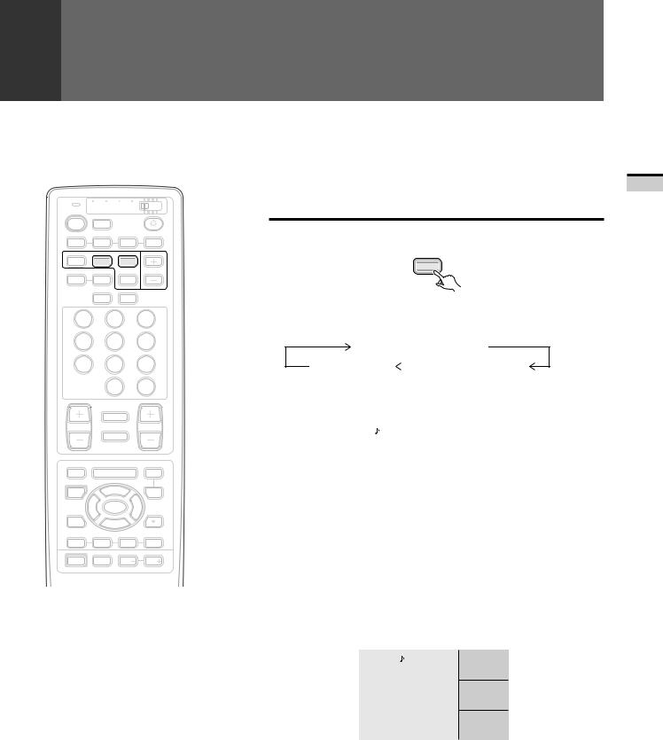
∙Each time the SEARCH button is pressed, the screen mode changes in the following order.
Normal screen/SPLIT screen
3-SEARCH screen |
|
9-SEARCH screen |
|
||
|
|
|
1 9-SEARCH screen
A N T . A 3 6 |
1 |
4 |
8 |
|
|
|
|
|
|
|
|
|
1 2 |
1 8 |
3 0 |
|
|
|
|
|
4 1 |
4 9 |
5 2 |
|
|
|
|
Main picture |
Search picture |
||
∙Onthesearchpicture,thepresetchannel(seepage52)willbedisplayed as a frozen image. If 9 or more channels have been preset, the screens will automatically be switched and displayed.
∙The search picture cannot be operated.
∙If the channel or input source is changed, SEARCH screen mode will turn off.
2 3-SEARCH screen
A N T . A 3 6 |
A 4 |
A 1 0
B 8
Main picture |
Search picture |
∙Press the SELECT button to select image that you wish to switch the channel or input source to. When the color of the channel or input indicator changes to yellow, screen operations can be performed. (Use only the selector buttons, direct channel selection buttons, ANT button and CH +,- buttons.)
∙Sound output is limited to the main picture.
15
TV WATCH TO
<ARB1526>
CHECKING THE MENU
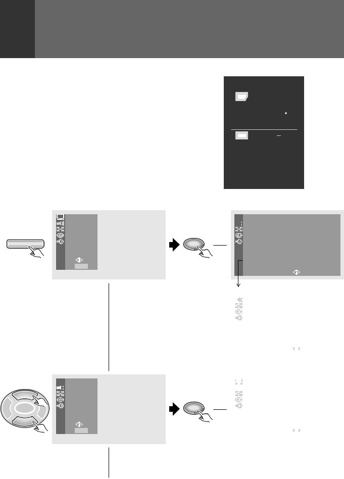
Press MENU on the remote control unit.
The MAIN MENU will be displayed on the screen.
Selectthedesiredmenuitemusing 5or buttonoftheremote control unit, and press SET/ENTER button to perform the desired operations and settings.
•When the menu screen appears, the mode will switch from SCREEN to FULL. When all menu selections have been made, the previous screen mode will be restored.
EDIT/ |
|
DVD |
LEARN |
MENU |
MENU |
SOURCE |
5 |
SAT |
POWER |
GUIDE |
|
2 |
ENTERSET/ |
3 |
FAVORITE CH  VCR REC
1 7 3 ¡
RECEIVER
POWER |
INPUT |
VOL |
VOL |
PROJECTION MONITOR RECEIVER |
Î |
REMOTE CONTROL UNIT |
|
PICTURE |
|
SOUND |
|
SCREEN |
|
CC |
MENU |
SET UP |
|
US E: |
|
END: MENU |
 PICTURE


 SOUND
SOUND
5SCREEN
|
|
CC |
2 ENTERSET/ |
3 |
SET UP |
|
|
US E: |
|
|
END: MENU |
16
SET/
ENTER
SET/
ENTER
PICTURE adjustment menu (See page 18)
 PICTURE


 MOD E : U S E R ( MO V I E )
|
C ON T R A S T |
– 1 0 |
|
|
|
|
|
|
|
|
|
|
|
|
|
|
|
|
|
|
|
|
|
|
|
|
|
|
|
|
|
|
|
|
|
|
|
|
|
|
|
|
|
|
|
|
|
|
|
|
|
|
|
|
|
|
|
|
|
|
|
|
|
|
|
|
|
|
|
|
|
|
|
|
|
|
|
|
|
|
|
|
|
|
|
|
|
|
|
|
|||||||||||||||||||||||||||||||||||
|
B L A C K |
L V L . |
5 |
|
|
|
|
|
|
|
|
|
|
|
|
|
|
|
|
|
|
|
|
|
|
|
|
|
|
|
|
|
|
|
|
|
|
|
|
|
|
|
|
|
|
|
|
|
|
|
|
|
|
|
|
|
|
|
|
|
|
|
|
|
|
|
|
|
|
|
|
|
|
|
|
|
|
|
|
|
|
|
|
|
|
|
|
|
|
|
|
|
|
|
|
|
|
|
|
|
|
|
|
|
|
|
|
|
|
|
|
|
|
|
|
|
|
|
|
|
|
|
|||
|
|
|
|
|
|
|
|
|
|
|
|
|
|
|
|
|
|
|
|
|
|
|
|
|
|
|
|
|||||||||||||||||||||||||||||||||||
|
|
|
|
|
|
|
|
|
|
|
|
|
|
|
|
|
|
|
|
|
|
|
|
|
|
|
|
|||||||||||||||||||||||||||||||||||
|
C O L OR |
|
2 |
|
|
|
|
|
|
|
|
|
|
|
|
|
|
|
|
|
|
|
|
|
|
|
|
|
|
|
|
|
|
|
|
|
|
|
|
|
|
|
|
|
|
|
|
|
|
|
|
|
|
|
|
|
|
|
|
|
|
|
|
|
|
|
|
|
|
|
|
|
|
|
|
|
|
|
|
|
|
|
|
|
|
|
|
|
|
|
|
|
|
|
|
|
|
|
|
|
|
|
|
|
|
|
|
|
|
|
|
|
|
|
|
|
|
|
|
|
|
|
|
||
|
|
|
|
|
|
|
|
|
|
|
|
|
|
|
|
|
|
|
|
|
|
|
|
|
|
|
|
|
||||||||||||||||||||||||||||||||||
|
|
|
|
|
|
|
|
|
|
|
|
|
|
|
|
|
|
|
|
|
|
|
|
|
|
|
|
|
||||||||||||||||||||||||||||||||||
|
T I N T |
|
3 |
|
|
|
|
|
|
|
|
|
|
|
|
|
|
|
|
|
|
|
|
|
|
|
|
|
|
|
|
|
|
|
|
|
|
|
|
|
|
|
|
|
|
|
|
|
|
|
|
|
|
|
|
|
|
|
|
|
|
|
|
|
|
|
|
|
|
|
|
|
|
|
|
|
|
|
|
|
|
|
|
|
|
|
|
|
|
|
|
|
|
|
|
|
|
|
|
|
|
|
|
|
|
|
|
|
|
|
|
|
|
|
|
|
|
|
|
|
|
|
|
||
|
|
|
|
|
|
|
|
|
|
|
|
|
|
|
|
|
|
|
|
|
|
|
|
|
|
|
|
|
||||||||||||||||||||||||||||||||||
|
S H A R P |
|
– 1 0 |
|
|
|
|
|
||||||||||||||||||||||||||||||||||||||||||||||||||||||
|
|
|
|
|
|
|
|
|
|
|
|
|
|
|
|
|
|
|
|
|
|
|
|
|
|
|
|
|
|
|
|
|
|
|
|
|
|
|
|
|
|
|
|
|
|
|
|
|
|
|
|
|
|
|
|
|
|
|
|
|
||
|
|
|
|
|
|
|
|
|
|
|
|
|
|
|
|
|
|
|
|
|
|
|
|
|
|
|
|
|
||||||||||||||||||||||||||||||||||
|
O T H E R |
|
|
|
|
|
|
|
|
|
|
|
|
|
|
|
|
|
|
|
|
|
|
|
|
|
|
|
|
|
|
|
|
|
|
|
|
|
|
|
|
|
|
|
|
|
|
|
|
|
|
|
|
|
|
|
|
|
|
|
|
|
|
|
|
|
|
|
|
|
|
|
|
|
|
|
|
|
|
|
|
|
|
|
|
|
|
|
|
|
|
|
|
|
|
|
|
|
|
|
|
|
|
|
|
|
|
|
|
|
|
|
|
|
|
|
|
|
|
|
|
|
|
|
|
|
|
|
|
|
|
|
|
|
|
|
|
|
|
|
|
|
|
|
|
|
|
|
|
|
|
|
|
|
|
|
|
|
|
|
|
|
|
|
|
|
|
|
|
|
|
|
|
|
|
|
|
|
|
|
|
|
|
|
|
|
|
|
|
E X I T |
|
|
|
|
|
|
|
|
|
|
|
|
|
|
|
|
|
|
|
|
|
|
|
|
|
|
|
|
|
|
|
|
|
|
|
|
|
|
|
|
|
|
|
|
|
|
|
|
|
|
|
|
|
|
|
|
|
|
|
|
|
|
USE: |
|
|
|
|
|
|
|
|
|
|
|
|
|
|
|
|
END: |
|
MENU |
||||||||||||||||||||||||||||||||||||||||||
|
||||||||||||||||||||||||||||||||||||||||||||||||||||||||||||||
|
|
|
|
|
|
|
|
|
|
|
|
PICTURE |
|
|
|
|
|
|
|
|
|
|
|
|
||
|
|
|
O T H E R |
|
|
|
|
|
|
|
|
|
|
|
|
||
|
|
|
|
3 D Y / C L E V E L : 3 |
|
|
|
|
|
|
|
|
|
|
|
||
|
|
|
|
3 D NR |
L E V E L : 3 |
|
|
|
|
|
|
|
|
|
|
||
|
|
|
|
C NR : O F F |
|
|
|
|
|
|
|
|
|
|
|
||
|
|
|
|
C O L O R |
T EMP : M I D |
|
|
|
|
|
|
|
|
|
|
||
|
|
|
|
F L E S H |
T O N E : O N |
|
|
|
|
|
|
|
|
|
|
||
|
|
|
|
|
|
|
||
|
|
|
|
E X I T |
|
|
|
|
|
|
|
|
US E: |
END: |
MENU |
|
|
|
|
|
|
|
|
|
|
|
SOUND adjustment menu (See page 25)
|
|
|
|
|
|
|
|
|
|
|
|
|
|
SOUND |
|
|
|
|
|
|
|
|
|
|
|
MT S : MA I N |
|
|
|
|
|
|
|
|
|
|
|
|
|
|
|||
|
|
|
|
B A S S |
|
– 1 0 |
|
|
|
|
|
|
|
|
T R E B L E |
|
5 |
|
|
|
|
|
|
|
|
B A L A N C E |
|
R 2 |
|
|
|
|
|
|
|
|
S URROUND : TruSurround |
|
|||||
|
|
|
|
|
||||||
|
|
|
|
E X I T |
|
|
|
|
|
|
|
|
|
|
USE: |
|
|
END: |
MENU |
|
|
|
|
|
|
|
|
|
|
|
|
|
<ARB1526>
5 
2ENTERSET/
5 
2ENTERSET/
5 
2ENTERSET/
 PICTURE


 SOUND
SOUND
 SCREEN
 CC
CC
3 SET UP
US E: 


END: MENU
 PICTURE


 SOUND
SOUND
 SCREEN
 CC
CC
3 SET UP
US E: 


END: MENU
 PICTURE


 SOUND
SOUND
 SCREEN
 CC
CC
3 SET UP
US E: 


END: MENU
CHECKING THE MENU
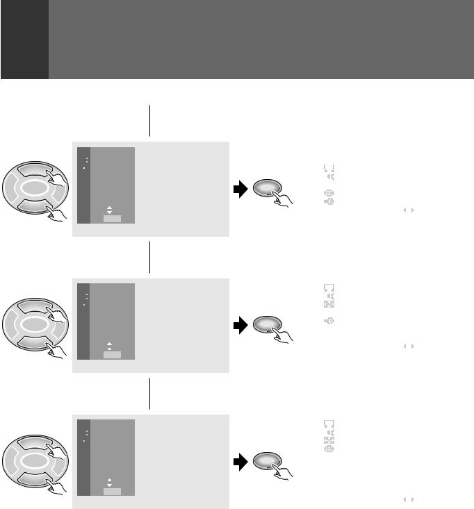
SCREEN setting menu (See page 28)
|
|
|
|
|
|
|
|
|
|
|
|
|
|
|
|
|
|
|
|
SCREEN |
|
|
|
|
|
|
|
|
|
|
|
|
|
C I N EMA |
W I D E |
|
|
|
|
|
|
|
|
|
|
|
|
|
|
|
|
|
|||
SET/ |
|
|
|
|
|
|
A U T O |
S C R E E N : O F F |
|
|
|
|
|
|
|
|
|
|
|
|
|
|
|
|
|||
ENTER |
|
|
|
|
|
|
V . P O S I T I O N : – 1 0 |
|
|
|
|
|
|
|
|
|
|
|
|
|
|
|
|
|
|
||
|
|
|
|
|
|
|
E X I T |
|
|
|
|
|
|
|
|
|
|
|
|
|
US E: |
END: |
MENU |
|
|
|
|
|
|
|
|
|
|
|
|
|
|
|
|
|
ADJUSTMENTS |
SET/ |
|
Closed Caption menu (See page 31) |
|||||||||||
|
|
|
|
||||||||||
|
|
|
|
|
|
|
|
|
|
|
|
|
|
|
|
|
|
|
|
|
|
|
|
|
|
|
|
|
|
|
|
|
|
CC |
|
|
|
|
|
|
|
|
|
|
|
|
|
|
C C : O F F |
|
|
|
|
|
|
|
|
|
|
|
|
|
|
|
|
|
|
||
ENTER |
|
|
|
|
|
|
MO D E : C C – 2 |
|
|
|
|
AND |
|
|
|
|
|
|
|
|
|
|
|
||||
|
|
|
|
|
|
|
|
|
|
||||
|
|
|
|
|
|
E X I T |
|
|
|
|
|
||
|
|
|
|
|
|
|
|
|
|
|
|||
|
|
|
|
|
|
|
|
|
|
|
|
||
|
|
|
|
|
|
|
US E: |
END: |
MENU |
|
|||
|
|
|
|
|
|
|
|
|
|
|
|
|
SETTINGS |
|
|
|
|
|
|
SET UP |
|
|
|
|
|||
|
|
SET UP menu (See pages 37 and 52) |
|
|
|||||||||
|
|
|
|
|
|
|
|
|
|
|
|
|
|
|
|
|
|
|
|
|
C H A NN E L S E T U P |
|
|
|
|
|
|
|
|
|
|
|
|
|
|
|
|
|
|
||
|
|
|
|
|
|
|
|
|
|
|
|
||
|
|
|
|
|
|
|
C ON V E RG E N C E |
|
|
|
|
|
|
|
|
|
|
|
|
|
|
|
|
|
|
||
|
|
|
|
|
|
|
D P O : O F F |
|
|
|
|
|
|
|
|
|
|
|
|
|
|
|
|
|
|
||
SET/ |
|
|
|
|
|
|
S Y S T EM I N / OU T |
|
|
|
|
|
|
|
|
|
|
|
|
|
|
|
|
|
|||
ENTER |
|
|
|
|
|
|
L A NGU A G E : E NG L I S H |
|
|
|
|||
|
|
|
|
|
|
|
|
|
|
||||
|
|
|
|
|
|
|
E X I T |
|
|
|
|
|
|
|
|
|
|
|
|
|
US E: |
END: |
MENU |
|
|
|
|
|
|
|
|
|
|
|
|
|
|
|
|
|
|
On screen indicators
USE: Indicates in light blue the buttons that can be used on the menu screen displayed.
END: End is for turning off the menu screen by pressing the MENU button.
EXIT: To return to the previous menu screen, use the 5or button to move to EXIT and then press SET/ENTER.
17
<ARB1526>
PICTURE ADJUSTMENTS
|
TV |
CBL VCR DVD |
||
TV |
|
/SAT |
/LD |
|
POWER |
|
TV |
|
|
|
|
INPUT |
|
|
1 |
|
2 |
3 |
4 |
SPLIT |
SEARCH |
SELECT |
|
|
SCREEN |
|
SUB CH |
||
MODE |
AUTO |
FREEZE |
|
|
|
|
ANT |
DISPLAY |
|
1 |
|
2 |
|
3 |
4 |
|
5 |
|
6 |
7 |
|
8 |
|
9 |
|
|
0 |
|
CH |
|
|
|
ENTER |
|
|
¢ CH |
|
|
|
|
|
RETURN |
|
|
CH |
|
|
|
VOL |
|
|
MUTING |
|
|
|
4 |
|
|
|
EDIT/ |
|
|
|
DVD |
LEARN |
|
MENU |
MENU |
|
SOURCE |
|
5 |
|
SAT |
POWER |
|
|
GUIDE |
|
|
2 |
ENTERSET/ |
3 |
|
FAVORITE CH  VCR REC
1 7 3 ¡
RECEIVER
POWER |
INPUT |
VOL |
VOL |
PROJECTION MONITOR RECEIVER |
Î |
REMOTE CONTROL UNIT |
NOTES on GAME mode setting:
∙We do not recommend the use of the Monitor for video games, still pictures, or computers due to the potential damage to the CRTs. In the event a consumer needs to use these devices for a short period of time, the GAME mode will minimize potential damage to the CRTs by lowering the relative contrast.
∙All signals output from the Projection Monitor will be unaffected. Only the original output signal is sent through the output jacks.
18
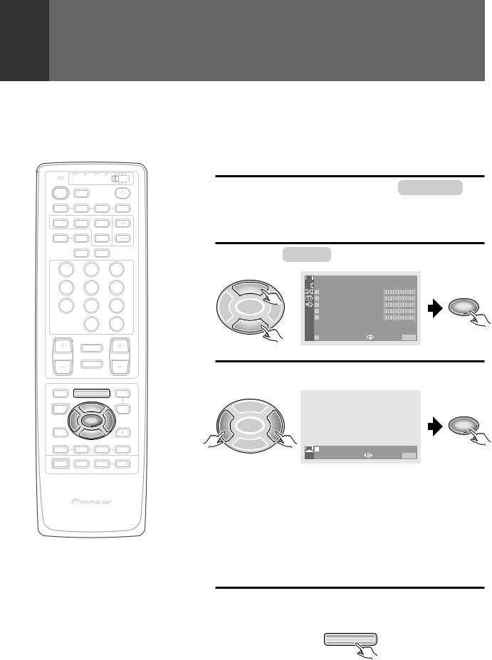
This device has three types of picture quality settings in memory. You can select your favorite from them or set the picture quality you desire and store it in memory.
RECALL THE DESIRED SETTINGS
1 Press MENU and select PICTURE by usingthe5or buttonandthenpressing
SET/ENTER. (Refer to page 16.)
2 Select MODE in the same way.


 PICTURE
5


 MO D E : U S E R ( MO V I E )
|
|
|
C O N T R A S T |
– 1 0 |
|
|
|
|
B L A C K L V L . |
5 |
|
2 |
SET/ |
3 |
C O L O R |
2 |
SET/ |
ENTER |
T I N T |
3 |
ENTER |
||
|
|
|
S H A R P |
– 1 0 |
|
 O T H E R
|
|
E X I T |
USE: |
END: MENU |
3 |
Select the desired setting. |
|||
|
5 |
|
|
|
2 |
SET/ |
3 |
|
SET/ |
ENTER |
|
ENTER |
||
|
|
MO D E : S T D |
MOV I E |
GAME USER |
|
|
|
US E: |
END: MENU |
STD ............ Sets standard picture quality.
MOVIE........ Reduces contrast making dark images easier to see. Effectiveformoviesthathavemanydarkimagessuch as night scenes etc..
GAME ........ Lowers the relative contrast of TV game and personal computer images to minimize discomfort to the eyes. Thiswillminimizebadeffectssuchasdiscoloredspots or stains on the CRT of the Monitor.
USER ......... Calls up the picture quality the user has set. See page 19 for setting.
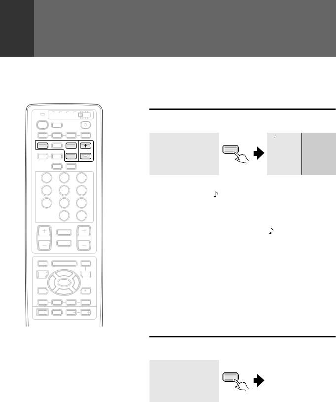
4 After setting, press MENU to turn the menu off.
MENU
<ARB1526>
|
|
|
|
PICTURE ADJUSTMENTS |
|
|
|
STORING THE SET PICTURE QUALITY |
|
|
|
|
IN MEMORY |
|
|
|
|
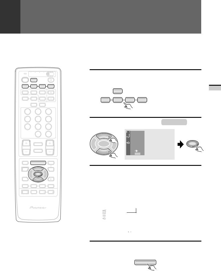
USER mode can be set for each input source: TV and INPUT 1 to INPUT 4. |
|
TV |
TV CBL VCR DVD |
1 |
Select the input source and show the |
|
|
/SAT |
/LD |
|
image on the screen. |
POWER |
INPUT |
|
|
|
TV |
|
|
|
|
1 |
2 |
3 |
4 |
SPLIT SEARCH SELECT
SCREEN |
SUB CH |
MODE AUTO FREEZE
ANT DISPLAY
1 2 3
4 5 6
7 8 9
|
0 |
CH |
|
ENTER |
|
¢ CH |
|
|
|
RETURN |
|
CH |
|
VOL |
|
MUTING |
|
4 |
|
|
EDIT/ |
|
DVD |
LEARN |
MENU |
MENU |
SOURCE |
5 |
SAT |
POWER |
GUIDE |
|
2 |
ENTERSET/ |
3 |
FAVORITE CH  VCR REC
1 7 3 ¡
RECEIVER
POWER |
INPUT |
VOL |
VOL |
PROJECTION MONITOR RECEIVER |
Î |
REMOTE CONTROL UNIT |
TV |
|
|
INPUT |
|
If VCR or DVD/LD has been |
|
1 |
2 |
3 |
4 |
||
selected, start playback for the |
|||||
|
|
|
|
||
|
|
|
|
relevant device. |
2 Press MENU and select PICTURE .


 PICTURE
5


 SOUND
SOUND
 SCREEN
 CC
CC
2 |
SET/ |
3 |
SET UP |
SET/ |
ENTER |
ENTER |
|||
|
|
|
USE: |
|
|
|
END: MENU |
|
3 Adjust the desired picture quality. (Refer to steps 2 and 3 on page 20.)
∙If any mode (STD, MOVIE, or GAME) is adjusted, USER mode will be entered.
∙The last mode that was adjusted will become the USER sub mode (indicated in parentheses).
∙A USER mode can be stored for TV, and the four input sources.
|
|
|
|
|
|
|
|
|
|
|
|
|
|
|
|
PICTURE |
|
|
|
|
|
|
|
|
|
Indicates the adjusted picture |
|
|
|
|
MOD E : U S E R |
( S T D ) |
|
|
|
|
|
||||
|
|
|
|
|
|
|
|
||||||
|
|
|
C ON T R A S T |
|
– 1 0 |
|
|
|
|
|
|
quality setting that is the base |
|
|
|
|
B L A C K |
L V L . |
5 |
|
|
|
|
|
|
||
|
|
|
C O L OR |
|
|
2 |
|
|
|
|
|
|
for USER mode. |
|
|
|
T I N T |
|
|
3 |
|
|
|
|
|
|
|
|
|
|
S H A R P |
|
|
– 1 0 |
|
|
|
|
|
|
|
|
|
|
O T H E R |
|
|
|
|
|
|
|
|
|
|
|
|
|
E X I T |
|
|
|
|
|
|
|
|
|
|
|
|
|
US E: |
|
|
|
END: |
MENU |
|
|
|
||
|
|
|
|
|
|
|
|
|
|
|
|
|
|
4 After adjusting, press MENU to turn the menu off.
MENU
19
SETTINGS AND ADJUSTMENTS
<ARB1526>
PICTURE ADJUSTMENTS
|
TV |
CBL VCR DVD |
||
TV |
|
/SAT |
/LD |
|
POWER |
|
TV |
|
|
|
|
INPUT |
|
|
1 |
|
2 |
3 |
4 |
SPLIT |
SEARCH |
SELECT |
|
|
SCREEN |
|
SUB CH |
||
MODE |
AUTO |
FREEZE |
|
|
|
|
ANT |
DISPLAY |
|
1 |
|
2 |
|
3 |
4 |
|
5 |
|
6 |
7 |
|
8 |
|
9 |
|
|
0 |
|
CH |
|
|
|
ENTER |
|
|
¢ CH |
|
|
|
|
|
RETURN |
|
|
CH |
|
|
|
VOL |
|
|
MUTING |
|
|
|
4 |
|
|
|
EDIT/ |
|
|
|
DVD |
LEARN |
|
MENU |
MENU |
|
SOURCE |
|
5 |
|
SAT |
POWER |
|
|
GUIDE |
|
|
2 |
ENTERSET/ |
3 |
|
FAVORITE CH  VCR REC
1 7 3 ¡
RECEIVER
POWER |
INPUT |
VOL |
VOL |
PROJECTION MONITOR RECEIVER |
Î |
REMOTE CONTROL UNIT |
NOTES:
•When DPO is on, CONTRAST, BLACK LEVEL and COLOR cannot be adjusted. (See page 62.)
•When picture quality has been adjusted, the user mode data will be overwritten with the new settings.
20
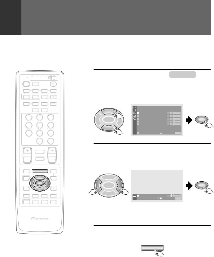
TO ADJUST THE PICTURE QUALITY
The CONTRAST, BLACK LEVEL (brightness), COLOR, TINT and SHARP (sharpness) can be adjusted.
1 |
Press MENU and select PICTURE . |
|
(Refer to page 16.) |
|
|
2 |
Select the adjustment item. |


 PICTURE
5


 MO D E : U S E R ( MO V I E )
|
|
|
C O N T R A S T |
– 1 0 |
|
|
|
|
B L A C K L V L . |
5 |
|
2 |
SET/ |
3 |
C O L O R |
2 |
SET/ |
ENTER |
T I N T |
3 |
ENTER |
||
|
|
|
S H A R P |
– 1 0 |
|
 O T H E R
E X I T USE:

 END: MENU
3 Adjust by pressing 2or 3.
∙The adjusting range is –30 to 30.
∙The numerical value comes down to press 2and comes up to press 3.
5
2 |
SET/ |
3 |
SET/ |
ENTER |
ENTER |
||
|
|
C O N T R A S T |
– 1 0 |
|
|
US E: |
END: MENU |
∙The set picture quality will be stored in memory as USER mode (see page 19).
∙Repeat steps 2 and 3 for other items.
4 After adjusting, press MENU to turn the menu off.
MENU
<ARB1526>
|
TV CBL VCR DVD |
|
|
TV |
/SAT |
/LD |
|
POWER |
TV |
|
|
|
INPUT |
|
|
1 |
2 |
3 |
4 |
SPLIT |
SEARCH |
SELECT |
|
SCREEN |
|
SUB CH |
|
MODE |
AUTO |
FREEZE |
|
ANT DISPLAY
1 2 3
4 5 6
7 8 9
|
0 |
CH |
|
ENTER |
|
¢ CH |
|
|
|
RETURN |
|
CH |
|
VOL |
|
MUTING |
|
4 |
|
|
EDIT/ |
|
DVD |
LEARN |
MENU |
MENU |
SOURCE |
5 |
SAT |
POWER |
GUIDE |
|
2 |
ENTERSET/ |
3 |
FAVORITE CH  VCR REC
1 7 3 ¡
RECEIVER
POWER |
INPUT |
VOL |
VOL |
PROJECTION MONITOR RECEIVER |
Î |
REMOTE CONTROL UNIT |
PICTURE ADJUSTMENTS
OTHER PICTURE QUALITY ADJUSTMENTS
The following six fine adjustments are available. 1 3D Y/C LEVEL
2 3D NR LEVEL
3 CNR (Color Noise Reduction)
4 COLOR TEMP (Color Temperature)
5 FLESH TONE
1 |
Press MENU and select PICTURE . |
|
(Refer to page 16.) |
|
|
2 |
Select OTHER . |
|
PICTURE |
5


 MO D E : U S E R ( MO V I E )
|
|
|
C O N T R A S T |
– 1 0 |
|
|
|
|
B L A C K L V L . |
5 |
|
2 |
SET/ |
3 |
C O L O R |
2 |
SET/ |
ENTER |
T I N T |
3 |
ENTER |
||
|
|
|
S H A R P |
– 1 0 |
|
 O T H E R
E X I T USE:

 END: MENU
3 1 To adjust 3D Y/C LEVEL
Perform this adjustment when noises appear at the color borders of the image.
NOTE:
This function can be used only when viewing a source that has been connected to the antenna or composite video input terminal.
Select 3D Y/C LEVEL .
|
|
|
PICTURE |
|
|
|
|
5 |
|
O T H E R |
|
|
|
|
|
3 D Y / C L E V E L : 3 |
|
|||
|
|
|
3 D N R L E V E L : 3 |
|
|
|
2 |
SET/ |
3 |
C N R : O F F |
|
SET/ |
|
ENTER |
C O L O R |
T EMP : M I D |
ENTER |
|||
|
|
|
F L E S H T O N E : O N |
|
|
|
|
|
|
|
|
|
|
|
|
|
E X I T |
USE: |
|
END: MENU |
|
Select the desired level. |
|
|
|||
|
5 |
|
|
|
|
|
2 |
SET/ |
3 |
|
|
|
SET/ |
ENTER |
|
|
|
ENTER |
||
|
|
|
3 D Y / C L E V E L : |
|
3 |
|
|
|
|
|
|||
|
|
|
|
US E: |
|
END: MENU |
|
|
1 |
2 |
3 |
4 |
5 |
|
Suitable for software |
Suitable for software |
||||
|
using dynamic images |
using still images |
||||
21
SETTINGS AND ADJUSTMENTS
<ARB1526>
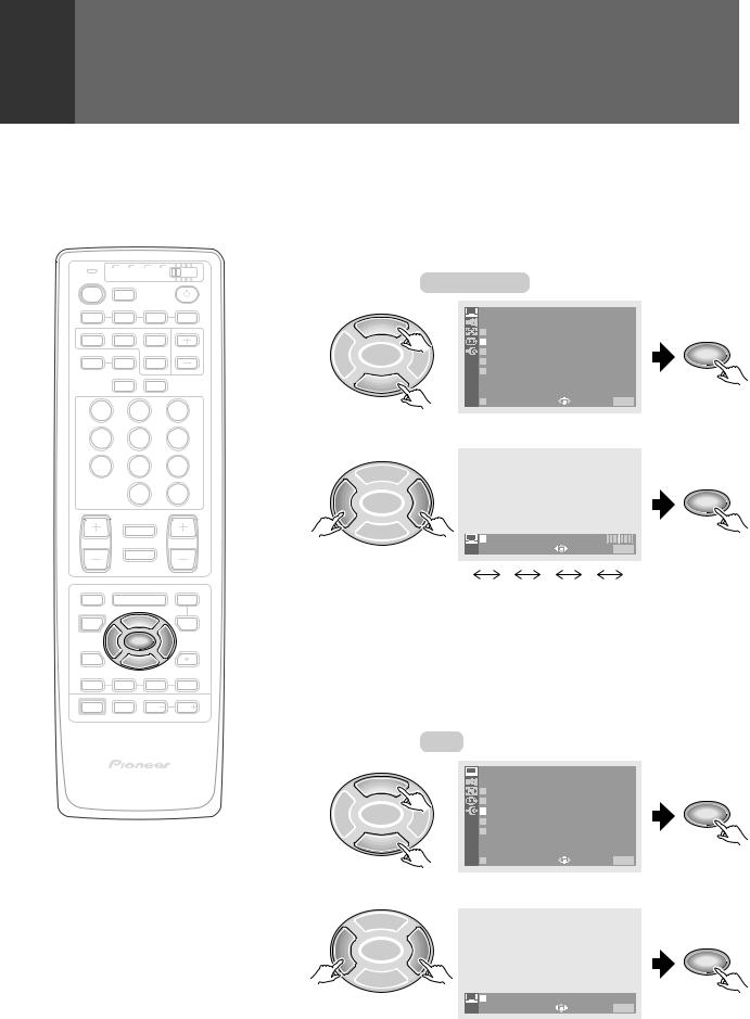
PICTURE ADJUSTMENTS
|
TV |
CBL VCR DVD |
||
TV |
|
/SAT |
/LD |
|
POWER |
|
TV |
|
|
|
|
INPUT |
|
|
1 |
|
2 |
3 |
4 |
SPLIT |
SEARCH |
SELECT |
|
|
SCREEN |
|
SUB CH |
||
MODE |
AUTO |
FREEZE |
|
|
|
|
ANT |
DISPLAY |
|
1 |
|
2 |
|
3 |
4 |
|
5 |
|
6 |
7 |
|
8 |
|
9 |
|
|
0 |
|
CH |
|
|
|
ENTER |
|
|
¢ CH |
|
|
|
|
|
RETURN |
|
|
CH |
|
|
|
VOL |
|
|
MUTING |
|
|
|
4 |
|
|
|
EDIT/ |
|
|
|
DVD |
LEARN |
|
MENU |
MENU |
|
SOURCE |
|
5 |
|
SAT |
POWER |
|
|
GUIDE |
|
|
2 |
ENTERSET/ |
3 |
|
FAVORITE CH  VCR REC
1 7 3 ¡
RECEIVER
POWER |
INPUT |
VOL |
VOL |
PROJECTION MONITOR RECEIVER |
Î |
REMOTE CONTROL UNIT |
22
2 To adjust 3D NR LEVEL
Reducesthenoiseleveloftheluminanceandchromanancesignals when there is S-VIDEO input.
NOTE:
This function can be used only when viewing a source that has been connected to the S-VIDEO input terminal.
Select 3D NR LEVEL .
|
|
|
PICTURE |
|
|
|
|
5 |
|
O T H E R |
|
|
|
|
|
3 D Y / C L E V E L : 3 |
|
|||
|
|
|
3 D N R L E V E L : 3 |
|
|
|
2 |
SET/ |
3 |
C N R : O F F |
|
SET/ |
|
ENTER |
C O L O R |
T EMP : M I D |
ENTER |
|||
|
|
|
F L E S H T O N E : O N |
|
|
|
|
|
|
|
|
|
|
|
|
|
E X I T |
USE: |
|
END: MENU |
|
Select the desired level. |
|
|
|||
|
5 |
|
|
|
|
|
2 |
SET/ |
3 |
|
|
|
SET/ |
ENTER |
|
|
|
ENTER |
||
|
|
|
3 D N R L E V E L : |
|
3 |
|
|
|
|
|
US E: |
|
END: MENU |
|
|
1 |
2 |
3 |
4 |
5 |
|
Low noise reduction |
|
|
High noise reduction |
||
3 ToadjustColorNoiseReduction(CNR)
Color noise can be reduced.
NOTE:
This function cannot be used when 1080i or 480p component signals have been input or when a DTV broadcast is being watched (with the digital tuner, sold separately).
Select CNR .
|
|
|
PICTURE |
|
|
|
5 |
|
O T H E R |
|
|
|
|
3 D Y / C L E V E L : 3 |
|
||
|
|
|
3 D N R L E V E L : 3 |
|
|
2 |
SET/ |
3 |
C N R : O F F |
SET/ |
|
ENTER |
C O L O R |
T EMP : M I D |
ENTER |
||
|
|
|
F L E S H T O N E : O N |
|
|
|
|
|
|
|
|
|
|
|
E X I T |
USE: |
END: MENU |
Set CNR to ON.
5
2 |
ENTERSET/ |
3 |
SET/ |
|
|
|
ENTER |
|
|
|
|
|
|
C N R : O N |
O F F |
|
|
US E: |
END: MENU |
<ARB1526>
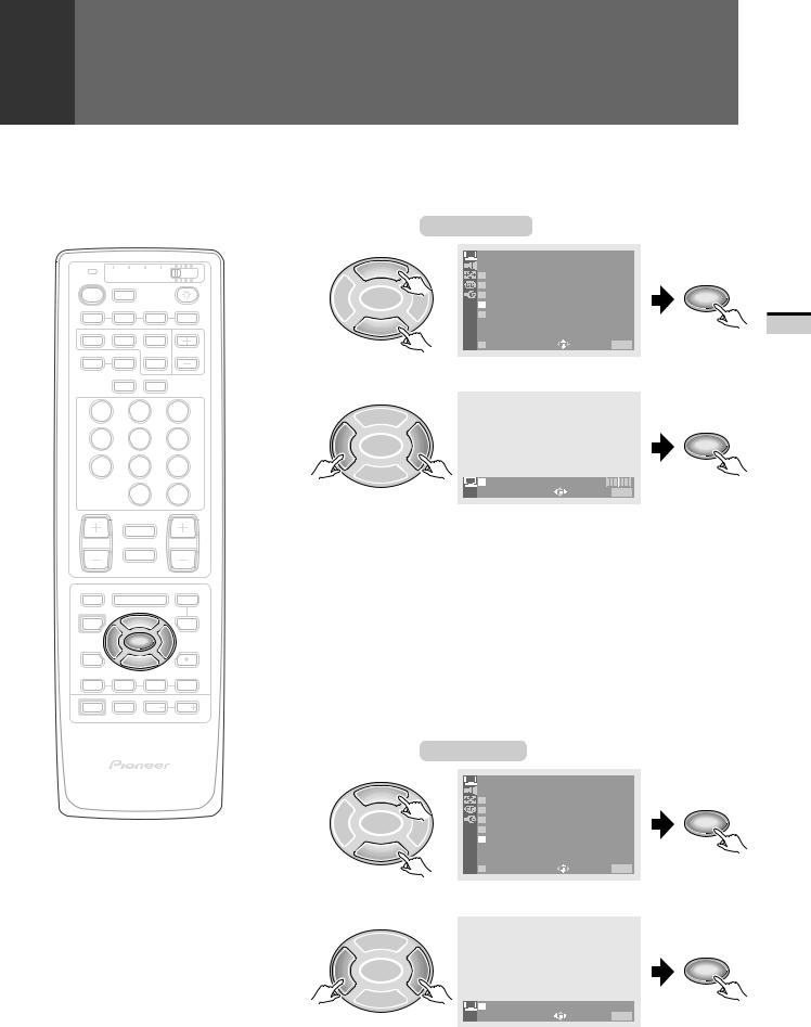
|
TV CBL VCR DVD |
|
|
TV |
/SAT |
/LD |
|
POWER |
TV |
|
|
|
INPUT |
|
|
1 |
2 |
3 |
4 |
SPLIT |
SEARCH |
SELECT |
|
SCREEN |
|
SUB CH |
|
MODE |
AUTO |
FREEZE |
|
ANT DISPLAY
1 2 3
4 5 6
7 8 9
|
0 |
CH |
|
ENTER |
|
¢ CH |
|
|
|
RETURN |
|
CH |
|
VOL |
|
MUTING |
|
4 |
|
|
EDIT/ |
|
DVD |
LEARN |
MENU |
MENU |
SOURCE |
5 |
SAT |
POWER |
GUIDE |
|
2 |
ENTERSET/ |
3 |
FAVORITE CH  VCR REC
1 7 3 ¡
RECEIVER
POWER |
INPUT |
VOL |
VOL |
PROJECTION MONITOR RECEIVER |
Î |
REMOTE CONTROL UNIT |
PICTURE ADJUSTMENTS
4 To adjust COLOR TEMPERATURE
This function enables the image to be set to three different tones.
Select COLOR TEMP .
|
|
|
PICTURE |
|
|
|
5 |
|
O T H E R |
|
|
|
|
3 D Y / C L E V E L : 3 |
|
||
|
|
|
3 D N R L E V E L : 3 |
|
|
2 |
SET/ |
3 |
C N R : O N |
T EMP : M I D |
SET/ |
ENTER |
C O L O R |
ENTER |
|||
|
|
|
F L E S H T O N E : O N |
|
|
|
|
|
|
|
|
|
|
|
E X I T |
USE: |
END: MENU |
Select the desired tone of the image.
5
2 |
SET/ |
3 |
|
SET/ |
ENTER |
|
ENTER |
||
|
|
|
C O L O R T EMP : M I D |
|
|
|
|
||
|
|
|
US E: |
END: MENU |
|
HIGH |
........ |
Cooler color |
|
|
MID .......... |
|
Normal color |
|
|
LOW ......... |
|
Warmer color |
|
5 To adjust FLESH TONE
By the time video signals from a broadcast station arrive at your projection monitor (on air or cable TV), they have experienced significant degradation.
Flesh tone reduces color noise, improves color uniformity and corrects unnatural flesh tones to give your natural images.
NOTE:
This function cannot be used when 1080i or 480p component signals have been input.
Select FLESH TONE .
|
|
|
PICTURE |
|
|
|
5 |
|
O T H E R |
|
|
|
|
3 D Y / C L E V E L : 3 |
|
||
|
|
|
3 D N R L E V E L : 3 |
|
|
2 |
SET/ |
3 |
C N R : O N |
T EMP : M I D |
SET/ |
ENTER |
C O L O R |
ENTER |
|||
|
|
|
F L E S H T O N E : O N |
|
|
|
|
|
|
|
|
|
|
|
E X I T |
USE: |
END: MENU |
|
Set FLESH TONE to ON. |
|
|||
|
5 |
|
|
|
|
2 |
SET/ |
3 |
|
|
SET/ |
ENTER |
|
|
ENTER |
||
|
|
|
F L E S H T O N E : O N O F F |
||
|
|
|
|
US E: |
END: MENU |
23
SETTINGS AND ADJUSTMENTS
<ARB1526>
 Loading...