

Page 1

Operating Instructions
AUDIO/VIDEO MUL
L
TI-CHANNE
Page 2
IMPORTANT
CAUTION
RISK OF ELECTRIC SHOCK
DO NOT OPEN
The lightning flash with arrowhead symbol,
within an equilateral triangle, is intended to
alert the user to the presence of uninsulated
"dangerous voltage" within the product's
enclosure that may be of sufficient
magnitude to constitute a risk of electric
shock to persons.
CAUTION:
TO PREVENT THE RISK OF ELECTRIC
SHOCK, DO NOT REMOVE COVER (OR
BACK). NO USER-SERVICEABLE PARTS
INSIDE. REFER SERVICING TO QUALIFIED
SERVICE PERSONNEL.
The exclamation point within an equilateral
triangle is intended to alert the user to the
presence of important operating and
maintenance (servicing) instructions in the
literature accompanying the appliance.
D3-4-2-1-1_En-A
Replacement and mounting of an AC plug on the power supply cord of this unit should be performed only by qualified service personnel.
IMPORTANT: THE MOULDED PLUG
This appliance is supplied with a moulded three pin mains plug for your safety and convenience. A 10 amp fuse is fitted in this plug. Should the fuse need to be replaced, please
ensure that the replacement fuse has a rating of 10 amps and that it is approved by ASTA or BSI to BS1362.
Check for the ASTA mark or the BSI mark on the body of the fuse.
If the plug contains a removable fuse cover, you must ensure that it is refitted when the fuse is replaced. If you lose the fuse cover the plug must not be used until a replacement
cover is obtained. A replacement fuse cover can be obtained from your local dealer.
If the fitted moulded plug is unsuitable for your socket outlet, then the fuse shall be removed and the plug cut off and disposed of safely. There is a danger of severe
electrical shock if the cut off plug is inserted into any 13 amp socket.
If a new plug is to be fitted, please observe the wiring code as shown below. If in any doubt, please consult a qualified electrician.
IMPORTANT: The wires in this mains lead are coloured in accordance with the following code:
Blue : Neutral Brown : Live
As the colours of the wires in the mains lead of this appliance may not correspond with the coloured markings identifying the terminals in your plug, proceed as follows ;
The wire which is coloured BLUE must be connected to the terminal which is marked with the letter N or coloured BLACK.
The wire which is coloured BROWN must be connected to the terminal which is marked with the letter L or coloured RED.
How to replace the fuse: Open the fuse compartment with a screwdriver and replace the fuse.
D3-4-2-1-2-2_B_En
WARNING
Before plugging in for the first time, read the following
section carefully.
The voltage of the available power supply differs
according to country or region. Be sure that the
power supply voltage of the area where this unit
WARNING
This equipment is not waterproof. To prevent a fire
or shock hazard, do not place any container filled
with liquid near this equipment (such as a vase or
flower pot) or expose it to dripping, splashing, rain
or moisture.
D3-4-2-1-3_B_En
will be used meets the required voltage (e.g., 230 V
or 120 V) written on the rear panel.
D3-4-2-1-4_A_En
VENTILATION CAUTION
WARNING
To prevent a fire hazard, do not place any naked
flame sources (such as a lighted candle) on the
equipment.
D3-4-2-1-7a_A_En
European model only
This product complies with the Low Voltage Directive
2006/95/EC and EMC Directive 2004/108/EC.
D3-4-2-1-9a_A_En
When installing this unit, make sure to leave space
around the unit for ventilation to improve heat
radiation (at least 60 cm at top, 10 cm at rear, and
30 cm at each side).
WARNING
Slots and openings in the cabinet are provided for
ventilation to ensure reliable operation of the
product, and to protect it from overheating. To
prevent fire hazard, the openings should never be
blocked or covered with items (such as newspapers,
table-cloths, curtains) or by operating the
equipment on thick carpet or a bed.
D3-4-2-1-7b_A_En
I
NP
U
T
S
E
L
E
CT
O
R
STANDBY/ON
L
1
L
2
L
3
L
4
S
C
-L
X9
A
CTI
L
5
0
VE
M
ON
I
TOR
R5
R4
R3
R2
R1
MAS
VO
TER
L
UME
Page 3
If the AC plug of this unit does not match the AC
outlet you want to use, the plug must be removed
and appropriate one fitted. Replacement and
mounting of an AC plug on the power supply cord of
this unit should be performed only by qualified
service personnel. If connected to an AC outlet, the
cut-off plug can cause severe electrical shock. Make
sure it is properly disposed of after removal.
The equipment should be disconnected by removing
the mains plug from the wall socket when left
unused for a long period of time (for example, when
on vacation).
D3-4-2-2-1a_A_En
CAUTION
The STANDBY/ON switch on this unit will not
completely shut off all power from the AC outlet.
Since the power cord serves as the main disconnect
device for the unit, you will need to unplug it from
the AC outlet to shut down all power. Therefore,
make sure the unit has been installed so that the
power cord can be easily unplugged from the AC
outlet in case of an accident. To avoid fire hazard,
the power cord should also be unplugged from the
AC outlet when left unused for a long period of time
(for example, when on vacation).
D3-4-2-2-2a_A_En
Operating Environment
Operating environment temperature and humidity:
+5 ºC to +35 ºC (+41 ºF to +95 ºF); less than 85 %RH
(cooling vents not blocked)
Do not install this unit in a poorly ventilated area, or in
locations exposed to high humidity or direct sunlight (or
strong artificial light)
D3-4-2-1-7c_A_En
This product is for general household purposes. Any
failure due to use for other than household purposes
(such as long-term use for business purposes in a
restaurant or use in a car or ship) and which
requires repair will be charged for even during the
warranty period.
K041_En
European model only
If you want to dispose this product, do not mix it with general household waste. There is a separate collection system for used
electronic products in accordance with legislation that requires proper treatment, recovery and recycling.
Private households in the member states of the EU, in Switzerland and Norway may return their used electronic products free of charge to
designated collection facilities or to a retailer (if you purchase a similar new one).
For countries not mentioned above, please contact your local authorities for the correct method of disposal.
By doing so you will ensure that your disposed product undergoes the necessary treatment, recovery and recycling and thus prevent potential
negative effects on the environment and human health.
K058_A_En
Changing the TV format setting
If the System Setup menu is not displayed correctly, it
may be that the TV system is set incorrectly for your
country or region.
With the amplifier in standby, press
1
STANDBY/ON
button.
2
Select
PAL/NTSC
NTSC
using
The display shows the new setting (PAL or NTSC).
while holding down the
using
/
, then select
/
.
SETUP
PAL
or
Page 4

Thank you for buying this Pioneer product. Please read through these operating instructions so you will know how to operate
your model properly. After you have finished reading the instructions, put them away in a safe place for future reference.
Contents
01 Before you start
Checking what’s in the box . . . . . . . . . . . . . . . . . . . . . . . 7
Installing the amplifier. . . . . . . . . . . . . . . . . . . . . . . . . . . 7
Loading the batteries. . . . . . . . . . . . . . . . . . . . . . . . . . . . 7
02 Simple Home Theater Guide
Introduction to home theater . . . . . . . . . . . . . . . . . . . . . 8
Listening to Surround Sound . . . . . . . . . . . . . . . . . . . . . 8
Selecting the speaker layout/usage pattern . . . . . . . . . 9
Normal surround connections (default setting) . . . . . 9
5.2-channel Bi-amp connections . . . . . . . . . . . . . . . . . 9
7.2-channel front Bi-amp connections . . . . . . . . . . . . 9
7.2-channel + Zone 2 connections . . . . . . . . . . . . . . 10
7.2-channel + speaker B connections . . . . . . . . . . . 10
Positioning and connecting the speakers . . . . . . . . . . 10
Normal surround connections (default setting). . . . 11
5.2-channel Bi-amp connections . . . . . . . . . . . . . . . . 11
7.2-channel front Bi-amp connections . . . . . . . . . . . 11
7.2-channel + Zone 2 connections . . . . . . . . . . . . . . 11
7.2-channel + speaker B connections . . . . . . . . . . . 11
Automatically setting up for surround sound
(MCACC & Full Band Phase Control) . . . . . . . . . . . . . . 11
Problems when using the Auto MCACC Setup . . . . 13
Playing a source. . . . . . . . . . . . . . . . . . . . . . . . . . . . . . . 13
Better sound using Phase Control and
Full Band Phase Control . . . . . . . . . . . . . . . . . . . . . . . . 14
Using Phase Control . . . . . . . . . . . . . . . . . . . . . . . . . . 14
Using Full Band Phase Control . . . . . . . . . . . . . . . . . 14
03 Connecting your equipment
Rear panel . . . . . . . . . . . . . . . . . . . . . . . . . . . . . . . . . . . 16
When making cable connections. . . . . . . . . . . . . . . . . 17
About the video converter . . . . . . . . . . . . . . . . . . . . . . . 18
Connecting using HDMI . . . . . . . . . . . . . . . . . . . . . . . . 18
About HDMI. . . . . . . . . . . . . . . . . . . . . . . . . . . . . . . . . 19
Connecting your TV and DVD player . . . . . . . . . . . . . . 20
Connecting your Blu-ray disc player . . . . . . . . . . . . . . 21
Connecting a satellite/cable receiver or
other set-top box . . . . . . . . . . . . . . . . . . . . . . . . . . . . . . 22
Connecting a DVD/HDD recorder, VCR and
other video sources . . . . . . . . . . . . . . . . . . . . . . . . . . . . 23
Using the component video jacks . . . . . . . . . . . . . . . . 24
Connecting digital audio sources. . . . . . . . . . . . . . . . . 25
About the WMA9 Pro decoder . . . . . . . . . . . . . . . . . . 25
Connecting analog audio sources . . . . . . . . . . . . . . . . 26
Connecting a component to
the front panel inputs . . . . . . . . . . . . . . . . . . . . . . . . . . 26
Installing your speaker system . . . . . . . . . . . . . . . . . . . 27
Connecting the speakers . . . . . . . . . . . . . . . . . . . . . . 28
Placing the speakers. . . . . . . . . . . . . . . . . . . . . . . . . . 28
THX speaker system setup . . . . . . . . . . . . . . . . . . . . . 29
Plugging in the amplifier. . . . . . . . . . . . . . . . . . . . . . . . 29
04 Controls and displays
Front panel. . . . . . . . . . . . . . . . . . . . . . . . . . . . . . . . . . . 30
Operating range of remote control unit . . . . . . . . . . 31
Remote control . . . . . . . . . . . . . . . . . . . . . . . . . . . . . . . 32
05 Listening to your system
Auto playback . . . . . . . . . . . . . . . . . . . . . . . . . . . . . . . . 34
Listening in surround sound . . . . . . . . . . . . . . . . . . . . 34
Standard surround sound . . . . . . . . . . . . . . . . . . . . . 34
Using the Home THX modes . . . . . . . . . . . . . . . . . . . 35
Using the Advanced surround effects . . . . . . . . . . . 35
Listening in stereo. . . . . . . . . . . . . . . . . . . . . . . . . . . . . 36
Using Front Stage Surround Advance. . . . . . . . . . . . . 36
Using Stream Direct . . . . . . . . . . . . . . . . . . . . . . . . . . . 36
Selecting MCACC presets . . . . . . . . . . . . . . . . . . . . . . 37
Choosing the input signal . . . . . . . . . . . . . . . . . . . . . . 37
Using surround back channel processing . . . . . . . . . 37
Using the Virtual Surround Back mode . . . . . . . . . . 38
Using the genre synchronizing function . . . . . . . . . . . 39
06 The System Setup menu
Making amplifier settings from
the System Setup menu . . . . . . . . . . . . . . . . . . . . . . . . 40
Automatic MCACC (Expert) . . . . . . . . . . . . . . . . . . . . . 40
Speaker output setting . . . . . . . . . . . . . . . . . . . . . . . . . 43
Manual MCACC setup . . . . . . . . . . . . . . . . . . . . . . . . . 44
Fine Channel Level . . . . . . . . . . . . . . . . . . . . . . . . . . . 44
Fine Speaker Distance . . . . . . . . . . . . . . . . . . . . . . . . 45
Fine-adjusting the positions of the speakers
(Precision Distance) . . . . . . . . . . . . . . . . . . . . . . . . . . 45
Standing Wave . . . . . . . . . . . . . . . . . . . . . . . . . . . . . . 46
Acoustic Calibration EQ Adjust. . . . . . . . . . . . . . . . . 47
Acoustic Calibration EQ Professional. . . . . . . . . . . . 47
Full Band Phase Control. . . . . . . . . . . . . . . . . . . . . . . . 49
Data Management . . . . . . . . . . . . . . . . . . . . . . . . . . . . 50
Manual speaker setup . . . . . . . . . . . . . . . . . . . . . . . . . 52
Speaker Setting. . . . . . . . . . . . . . . . . . . . . . . . . . . . . . 52
Channel Level . . . . . . . . . . . . . . . . . . . . . . . . . . . . . . . 53
Speaker Distance . . . . . . . . . . . . . . . . . . . . . . . . . . . . 54
X-Curve. . . . . . . . . . . . . . . . . . . . . . . . . . . . . . . . . . . . . 54
THX Audio Setting . . . . . . . . . . . . . . . . . . . . . . . . . . . 54
07 Other connections
Connecting an iPod . . . . . . . . . . . . . . . . . . . . . . . . . . . 56
Connecting your iPod to the amplifier . . . . . . . . . . . 56
iPod playback . . . . . . . . . . . . . . . . . . . . . . . . . . . . . . . 57
Watching photos and video content . . . . . . . . . . . . . 58
Switching the iPod operation mode . . . . . . . . . . . . . 58
Using the i.LINK interface . . . . . . . . . . . . . . . . . . . . . . 58
Checking the i.LINK inputs . . . . . . . . . . . . . . . . . . . . 59
About i.LINK . . . . . . . . . . . . . . . . . . . . . . . . . . . . . . . . 59
About PQLS rate control . . . . . . . . . . . . . . . . . . . . . . 59
Creating an i.LINK network . . . . . . . . . . . . . . . . . . . . 59
4
En
Page 5

Connecting the multichannel analog inputs. . . . . . . . 60
Selecting the multichannel analog inputs . . . . . . . . 60
Switching the speaker system . . . . . . . . . . . . . . . . . . . 61
Switching the speaker system according to
the playback environment (Application Manual) . . . . 62
Setting the speaker system for high sound quality
multi-channel music sources
(DVD Audio discs and SACDs) . . . . . . . . . . . . . . . . . 62
Setting the speaker system for movie sources. . . . . 62
Bi-amping your speakers . . . . . . . . . . . . . . . . . . . . . . . 62
Bi-wiring your speakers . . . . . . . . . . . . . . . . . . . . . . . . . 63
Connecting additional amplifiers . . . . . . . . . . . . . . . . . 63
MULTI-ZONE listening . . . . . . . . . . . . . . . . . . . . . . . . . . 64
Making MULTI-ZONE connections . . . . . . . . . . . . . . 64
Using the MULTI-ZONE controls . . . . . . . . . . . . . . . . 66
Connecting an IR receiver. . . . . . . . . . . . . . . . . . . . . . . 67
Switching components on and off using
the 12 volt trigger . . . . . . . . . . . . . . . . . . . . . . . . . . . . . . 67
Using this amplifier with a Pioneer plasma television
Using the SR+ mode with a Pioneer plasma television
Connecting a PC for Advanced MCACC output . . . . . 69
Advanced MCACC output using your PC . . . . . . . . . 70
. . . 68
. . . 69
08 Playback with HOME MEDIA GALLERY
inputs
Enjoying the Home Media Gallery . . . . . . . . . . . . . . . . 71
Usable free media servers . . . . . . . . . . . . . . . . . . . . . 71
PlaysForSure . . . . . . . . . . . . . . . . . . . . . . . . . . . . . . . . 71
DLNA CERTIFIED™ Audio/Video/Image Player . . . . 71
Supported file formats . . . . . . . . . . . . . . . . . . . . . . . . 71
Connecting to the network through LAN interface. . . 72
Using the USB interface . . . . . . . . . . . . . . . . . . . . . . . . 73
Confirming the IP Address . . . . . . . . . . . . . . . . . . . . . . 73
Connecting a USB device . . . . . . . . . . . . . . . . . . . . . . . 73
Readable USB devices . . . . . . . . . . . . . . . . . . . . . . . . 74
Readable data files . . . . . . . . . . . . . . . . . . . . . . . . . . . 74
Removing a USB device . . . . . . . . . . . . . . . . . . . . . . . 74
Starting the Home Media Gallery function . . . . . . . . . 74
Navigating the files and folders . . . . . . . . . . . . . . . . . 74
Selectable screen display . . . . . . . . . . . . . . . . . . . . . . 75
Using the Tool Menu. . . . . . . . . . . . . . . . . . . . . . . . . . 75
Media Navigator . . . . . . . . . . . . . . . . . . . . . . . . . . . . . 76
Screen Components . . . . . . . . . . . . . . . . . . . . . . . . . . 76
USB . . . . . . . . . . . . . . . . . . . . . . . . . . . . . . . . . . . . . . . 76
My Playlist . . . . . . . . . . . . . . . . . . . . . . . . . . . . . . . . . . 76
Enjoying movie files . . . . . . . . . . . . . . . . . . . . . . . . . . . . 76
Screen Components . . . . . . . . . . . . . . . . . . . . . . . . . . 77
Movie Player key guide . . . . . . . . . . . . . . . . . . . . . . . . 77
Time Search. . . . . . . . . . . . . . . . . . . . . . . . . . . . . . . . . 78
Slow Playback . . . . . . . . . . . . . . . . . . . . . . . . . . . . . . . 78
Add to My Playlist . . . . . . . . . . . . . . . . . . . . . . . . . . . . 78
Fast Forward/Fast Reverse . . . . . . . . . . . . . . . . . . . . . 78
Forward/Reverse (15 sec.) . . . . . . . . . . . . . . . . . . . . . 78
A-B Repeat Mode . . . . . . . . . . . . . . . . . . . . . . . . . . . . 78
Repeat Mode . . . . . . . . . . . . . . . . . . . . . . . . . . . . . . . . 79
Random Mode . . . . . . . . . . . . . . . . . . . . . . . . . . . . . . . 79
Enjoying music files . . . . . . . . . . . . . . . . . . . . . . . . . . . 79
Screen Components. . . . . . . . . . . . . . . . . . . . . . . . . . 79
Music Player key guide . . . . . . . . . . . . . . . . . . . . . . . 79
A-B Repeat Mode . . . . . . . . . . . . . . . . . . . . . . . . . . . . 80
Repeat Mode. . . . . . . . . . . . . . . . . . . . . . . . . . . . . . . . 80
Random Mode . . . . . . . . . . . . . . . . . . . . . . . . . . . . . . 80
Enjoying photo files. . . . . . . . . . . . . . . . . . . . . . . . . . . . 81
Screen Components. . . . . . . . . . . . . . . . . . . . . . . . . . 81
Photo Player key guide. . . . . . . . . . . . . . . . . . . . . . . . 81
Setting up the slideshow . . . . . . . . . . . . . . . . . . . . . . 82
Setting up BGM for the slideshow . . . . . . . . . . . . . . 82
Starting the slideshow . . . . . . . . . . . . . . . . . . . . . . . . 83
Rotating the image. . . . . . . . . . . . . . . . . . . . . . . . . . . 83
Repeating the slideshow . . . . . . . . . . . . . . . . . . . . . . 83
Playing the slideshow at random . . . . . . . . . . . . . . . 83
Other useful functions . . . . . . . . . . . . . . . . . . . . . . . . . 83
Search . . . . . . . . . . . . . . . . . . . . . . . . . . . . . . . . . . . . . 83
Sort . . . . . . . . . . . . . . . . . . . . . . . . . . . . . . . . . . . . . . . 84
Adding files to My Playlist . . . . . . . . . . . . . . . . . . . . . 84
Setup . . . . . . . . . . . . . . . . . . . . . . . . . . . . . . . . . . . . . . 85
Switching the server. . . . . . . . . . . . . . . . . . . . . . . . . . 87
Resetting to default . . . . . . . . . . . . . . . . . . . . . . . . . . 87
Other convenient features . . . . . . . . . . . . . . . . . . . . . 87
Confirming the existing Home Media Gallery
version . . . . . . . . . . . . . . . . . . . . . . . . . . . . . . . . . . . . . 87
Glossary . . . . . . . . . . . . . . . . . . . . . . . . . . . . . . . . . . . . . 88
Default Gateway . . . . . . . . . . . . . . . . . . . . . . . . . . . . . 88
DHCP (Dynamic Host Configuration Protocol)
Server. . . . . . . . . . . . . . . . . . . . . . . . . . . . . . . . . . . . . . 88
DLNA (Digital Living Network Alliance) . . . . . . . . . . 88
DNS (Domain Name Service) Server . . . . . . . . . . . . 88
Ethernet . . . . . . . . . . . . . . . . . . . . . . . . . . . . . . . . . . . . 88
IP (Internet Protocol) Address. . . . . . . . . . . . . . . . . . 88
LAN Cable . . . . . . . . . . . . . . . . . . . . . . . . . . . . . . . . . . 89
MAC (Media Access Control) Address . . . . . . . . . . . 89
Mass Storage Class devices . . . . . . . . . . . . . . . . . . . 89
PlaysForSure . . . . . . . . . . . . . . . . . . . . . . . . . . . . . . . . 89
Subnet mask . . . . . . . . . . . . . . . . . . . . . . . . . . . . . . . . 89
UPnP (Universal Plug and Play) . . . . . . . . . . . . . . . . 89
USB (Universal Serial Bus) . . . . . . . . . . . . . . . . . . . . 89
Windows Media Connect. . . . . . . . . . . . . . . . . . . . . . 89
Windows Media DRM . . . . . . . . . . . . . . . . . . . . . . . . 89
Windows Media Player. . . . . . . . . . . . . . . . . . . . . . . . 89
Details of compatible formats . . . . . . . . . . . . . . . . . . . 89
09 HDMI Control
Making the HDMI Control connections . . . . . . . . . . . 91
Setting the HDMI options. . . . . . . . . . . . . . . . . . . . . . . 92
Setting the HDMI Control mode . . . . . . . . . . . . . . . . 92
Before using synchronization . . . . . . . . . . . . . . . . . . . 92
Synchronized amp mode . . . . . . . . . . . . . . . . . . . . . . . 92
Synchronized amp mode operations . . . . . . . . . . . . 92
Canceling synchronized amp mode . . . . . . . . . . . . . 92
About HDMI Control . . . . . . . . . . . . . . . . . . . . . . . . . . . 93
En
5
Page 6

10 Other Settings
The Input Setup menu . . . . . . . . . . . . . . . . . . . . . . . . . . 94
Input function default and possible settings . . . . . . 95
Changing the OSD display language
(OSD Language). . . . . . . . . . . . . . . . . . . . . . . . . . . . . . . 95
The Other Setup menu . . . . . . . . . . . . . . . . . . . . . . . . . 96
Multi Channel Input Setup . . . . . . . . . . . . . . . . . . . . . 96
ZONE Video Setup. . . . . . . . . . . . . . . . . . . . . . . . . . . . 96
ZONE Audio Setup . . . . . . . . . . . . . . . . . . . . . . . . . . . 97
SR+ Setup for Pioneer plasma televisions . . . . . . . . 97
Select the OSD display’s background pattern
(Display Image) . . . . . . . . . . . . . . . . . . . . . . . . . . . . . . 98
11 Using other functions
Setting the Audio options . . . . . . . . . . . . . . . . . . . . . . . 99
Adjusting the surround B speaker delay
(Surr B DELAY) . . . . . . . . . . . . . . . . . . . . . . . . . . . . . 101
Setting the Video options . . . . . . . . . . . . . . . . . . . . . . 101
Making an audio or a video recording . . . . . . . . . . . . 102
Playing a different source when recording . . . . . . . 102
Reducing the level of an analog signal . . . . . . . . . . . 103
Using the sleep timer . . . . . . . . . . . . . . . . . . . . . . . . . 103
Switching the contents displayed on the LCD . . . . . 103
Dimming the display . . . . . . . . . . . . . . . . . . . . . . . . . . 103
Switching the HDMI output . . . . . . . . . . . . . . . . . . . . 103
Checking the settings of the sound
currently playing, etc. . . . . . . . . . . . . . . . . . . . . . . . . . 104
Resetting the system . . . . . . . . . . . . . . . . . . . . . . . . . . 104
Default system settings . . . . . . . . . . . . . . . . . . . . . . 105
12 Controlling the rest of your system
Setting the remote to control other components . . . 106
Selecting preset codes directly. . . . . . . . . . . . . . . . . . 106
Programming signals from other remote controls
Erasing one of the remote control button settings
Resetting the remote control presets. . . . . . . . . . . . . 107
Confirming preset codes . . . . . . . . . . . . . . . . . . . . . . . 108
Renaming input source names . . . . . . . . . . . . . . . . . 108
Direct function . . . . . . . . . . . . . . . . . . . . . . . . . . . . . . . 108
Multi Operation and System Off . . . . . . . . . . . . . . . . . 108
Programming a multi-operation or
a shutdown sequence. . . . . . . . . . . . . . . . . . . . . . . . 109
Using multi operations . . . . . . . . . . . . . . . . . . . . . . . 109
Using System off . . . . . . . . . . . . . . . . . . . . . . . . . . . . 110
Controls for TVs . . . . . . . . . . . . . . . . . . . . . . . . . . . . . . 110
Controls for other components. . . . . . . . . . . . . . . . . . 110
Operating other Pioneer components with
this unit’s sensor . . . . . . . . . . . . . . . . . . . . . . . . . . . . . 111
. . . 106
. . . . 107
13 Additional information
Speaker Setting Guide . . . . . . . . . . . . . . . . . . . . . . . . 112
Positional relationship between speakers and
monitor . . . . . . . . . . . . . . . . . . . . . . . . . . . . . . . . . . . 114
Troubleshooting. . . . . . . . . . . . . . . . . . . . . . . . . . . . . . 115
Power. . . . . . . . . . . . . . . . . . . . . . . . . . . . . . . . . . . . . 115
No sound . . . . . . . . . . . . . . . . . . . . . . . . . . . . . . . . . . 115
Other audio problems . . . . . . . . . . . . . . . . . . . . . . . 116
Video . . . . . . . . . . . . . . . . . . . . . . . . . . . . . . . . . . . . . 117
Settings . . . . . . . . . . . . . . . . . . . . . . . . . . . . . . . . . . . 117
Professional Calibration EQ graphical output . . . . 118
Display . . . . . . . . . . . . . . . . . . . . . . . . . . . . . . . . . . . . 118
Remote control . . . . . . . . . . . . . . . . . . . . . . . . . . . . . 119
i.LINK interface . . . . . . . . . . . . . . . . . . . . . . . . . . . . . 119
HDMI . . . . . . . . . . . . . . . . . . . . . . . . . . . . . . . . . . . . . 120
Important information regarding
the HDMI connection . . . . . . . . . . . . . . . . . . . . . . . . 121
HOME MEDIA GALLERY . . . . . . . . . . . . . . . . . . . . . 121
iPod messages . . . . . . . . . . . . . . . . . . . . . . . . . . . . . 123
i.LINK messages . . . . . . . . . . . . . . . . . . . . . . . . . . . . 123
Meaning of messages displayed when
the HDMI control function is set to ON . . . . . . . . . 123
HOME MEDIA GALLERY messages . . . . . . . . . . . . 124
Surround sound formats . . . . . . . . . . . . . . . . . . . . . . 125
Dolby . . . . . . . . . . . . . . . . . . . . . . . . . . . . . . . . . . . . . 125
DTS. . . . . . . . . . . . . . . . . . . . . . . . . . . . . . . . . . . . . . . 126
Windows Media Audio 9 Professional . . . . . . . . . . 126
About THX . . . . . . . . . . . . . . . . . . . . . . . . . . . . . . . . . . 127
About Neural - THX Surround . . . . . . . . . . . . . . . . . . 128
About open source related licenses . . . . . . . . . . . . . 129
Listening modes with different input signal formats
Stream direct with different input signal formats
Cautions on Handing . . . . . . . . . . . . . . . . . . . . . . . . . 146
Liquid crystal screen . . . . . . . . . . . . . . . . . . . . . . . . 146
Liquid crystal backlight . . . . . . . . . . . . . . . . . . . . . . 146
Cleaning the shiny surfaces of the panel and
the liquid crystal display window . . . . . . . . . . . . . . 146
Specifications . . . . . . . . . . . . . . . . . . . . . . . . . . . . . . . 147
Cleaning the unit. . . . . . . . . . . . . . . . . . . . . . . . . . . . . 148
Our philosophy . . . . . . . . . . . . . . . . . . . . . . . . . . . . . . 148
Features. . . . . . . . . . . . . . . . . . . . . . . . . . . . . . . . . . . 148
. . . 141
. . . 145
6
En
Page 7
Before you start
Chapter 1:
Before you start
01
Checking what’s in the box
An accessory box is supplied with this amplifier. It can be
used to store the supplied accessories other than the
Warranty card.
Please check that you’ve received the following supplied
accessories:
• Setup microphone (cable: 5 m)
• Remote control unit
• AA/IEC R6P dry cell batteries x2
• iPod control cable
•Power cord
• Wiping cloth
• Warranty card
• These operating instructions
Installing the amplifier
• When installing this unit, make sure to put it on a
level and stable surface.
Don’t install it on the following places:
– on a color TV (the screen may distort)
– near a cassette deck (or close to a device that gives off
a magnetic field). This may interfere with the sound.
– in direct sunlight
– in damp or wet areas
– in extremely hot or cold areas
– in places where there is vibration or other movement
– in places that are very dusty
– in places that have hot fumes or oils (such as a kitchen)
• Do not touch this amplifier’s bottom panel while the
power is turned on. The bottom panel gets hot when
the power is on, and touching it could cause burns.
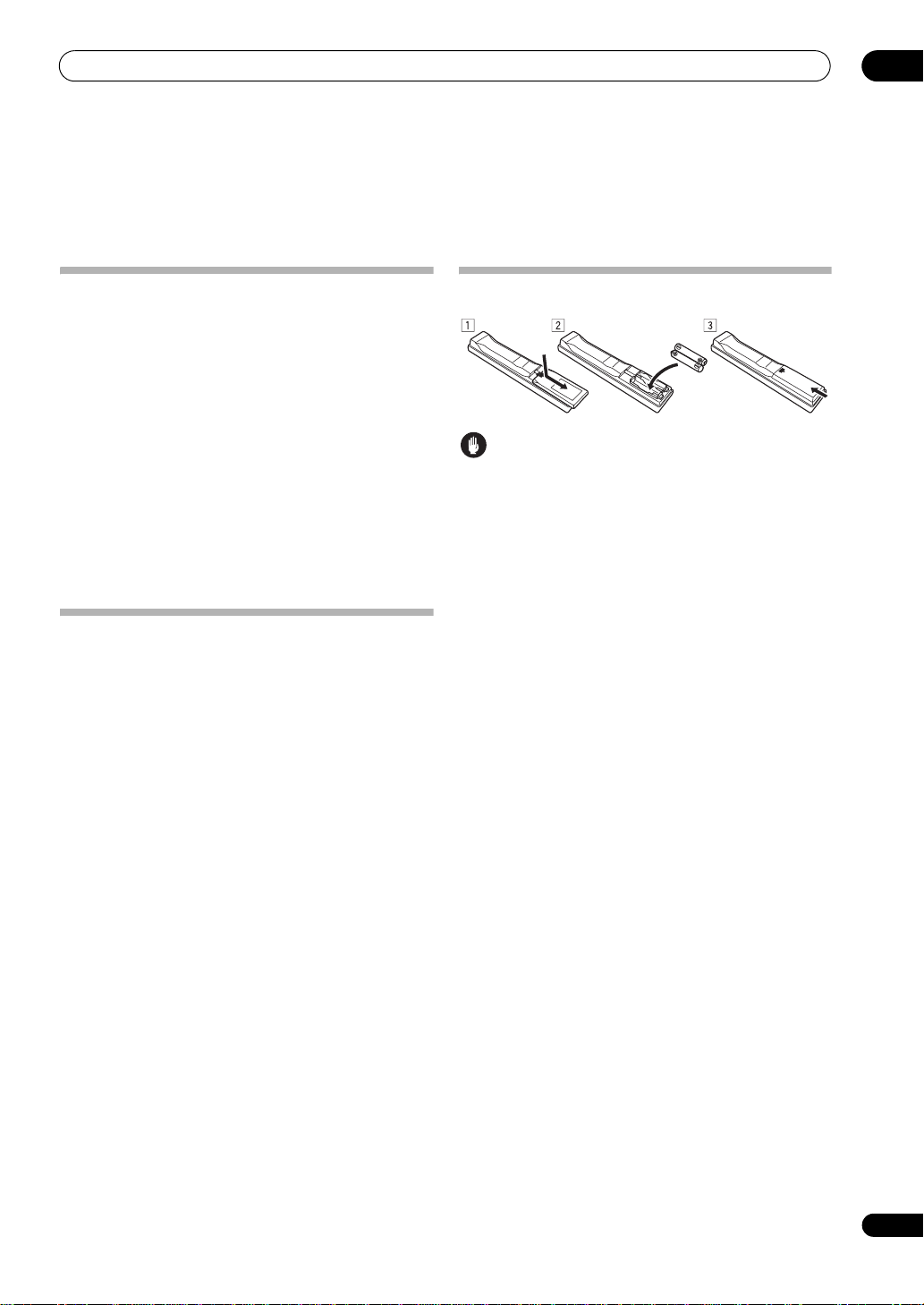
Loading the batteries
Caution
Incorrect use of batteries may result in such hazards as
leakage and bursting. Observe the following precautions:
• Never use new and old batteries together.
• Insert the plus and minus sides of the batteries
properly according to the marks in the battery case.
• Batteries with the same shape may have different
voltages. Do not use different batteries together.
• When disposing of used batteries, please comply
with governmental regulations or environmental
public instruction’s rules that apply in your country or
area.
• WARNING
Do not use or store batteries in direct sunlight or
other excessively hot place, such as inside a car or
near a heater. This can cause batteries to leak,
overheat, explode or catch fire. It can also reduce the
life or performance of batteries.
En
7
Page 8

02
Simple Home Theater Guide
Chapter 2:
Simple Home Theater Guide
5 Use the on-screen Auto MCACC Setup to set up your
Introduction to home theater
Home theater refers to the use of multiple audio tracks to
create a surround sound effect, making you feel like
you’re in the middle of the action or concert. The
surround sound you get from a home theater system
depends not only on your speaker setup, but also on the
source and the sound settings of the amplifier.
This amplifier will automatically decode multichannel
Dolby Digital, DTS, or Dolby Surround sources according
to your speaker setup. In most cases, you won’t have to
make changes for realistic surround sound, but other
possibilities (like listening to a CD with multichannel
surround sound) are explained in Listening to your
system on page 34.
system.
See Automatically setting up for surround sound (MCACC
& Full Band Phase Control) on page 11 for more on this.
6 Play a DVD, and adjust the volume to your liking.
Make sure that DVD/LD is showing in the amplifier’s
display, indicating that the DVD input is selected. If it
isn’t, press DVD on the remote control to set the
amplifier to the DVD input.
In addition to the basic playback explained in Playing a
source on page 13, there are several other sound options
you can select. See Listening to your system on page 34
for more on this.
See also Making amplifier settings from the System Setup
menu on page 40 for more setup options.
Listening to Surround Sound
This amplifier has been designed with the easiest
possible setup in mind. However, before proceeding to
the quick setup guide given below, you have to decide the
purpose of your speaker system and hook up your system
for surround sound. After the following quick setup, you
can simply leave the amplifier in the default settings in
most cases.
• Be sure to complete all connections before
connecting this unit to an AC power source.
1 Select the speaker usage method.
See Selecting the speaker layout/usage pattern on page 9.
2 Connect your speakers and place them for optimum
surround sound.
Connect your speakers as shown in Positioning and
connecting the speakers on page 10.
3 Connect your TV and DVD player.
See Connecting your TV and DVD player on page 20 to do
this. For surround sound, you’ll want to hook up using a
digital connection from the DVD player to the amplifier.
4 Plug in the amplifier and switch it on, followed by
your DVD player, your subwoofer and the TV.
Plug the power cable into the AC outlet and switch on the
amplifier.
TV to this amplifier. Check the manual that came with the
TV if you don’t know how to do this.
1
Make sure you’ve set the video input on your
• Set the subwoofer volume to a comfortable level.
8
En
Note
1 After this amplifier is connected to an AC outlet, a 15-second HDMI initialization process begins. You cannot carry out any operations during this process.
The HDMI indicator in the front LCD display blinks during this process, and you can turn on this amplifier once it has stopped blinking. When you set the
HDMI Control mode to OFF, you can skip this process. For details about the HDMI Control feature, see HDMI Control on page 91.
Page 9
Simple Home Theater Guide
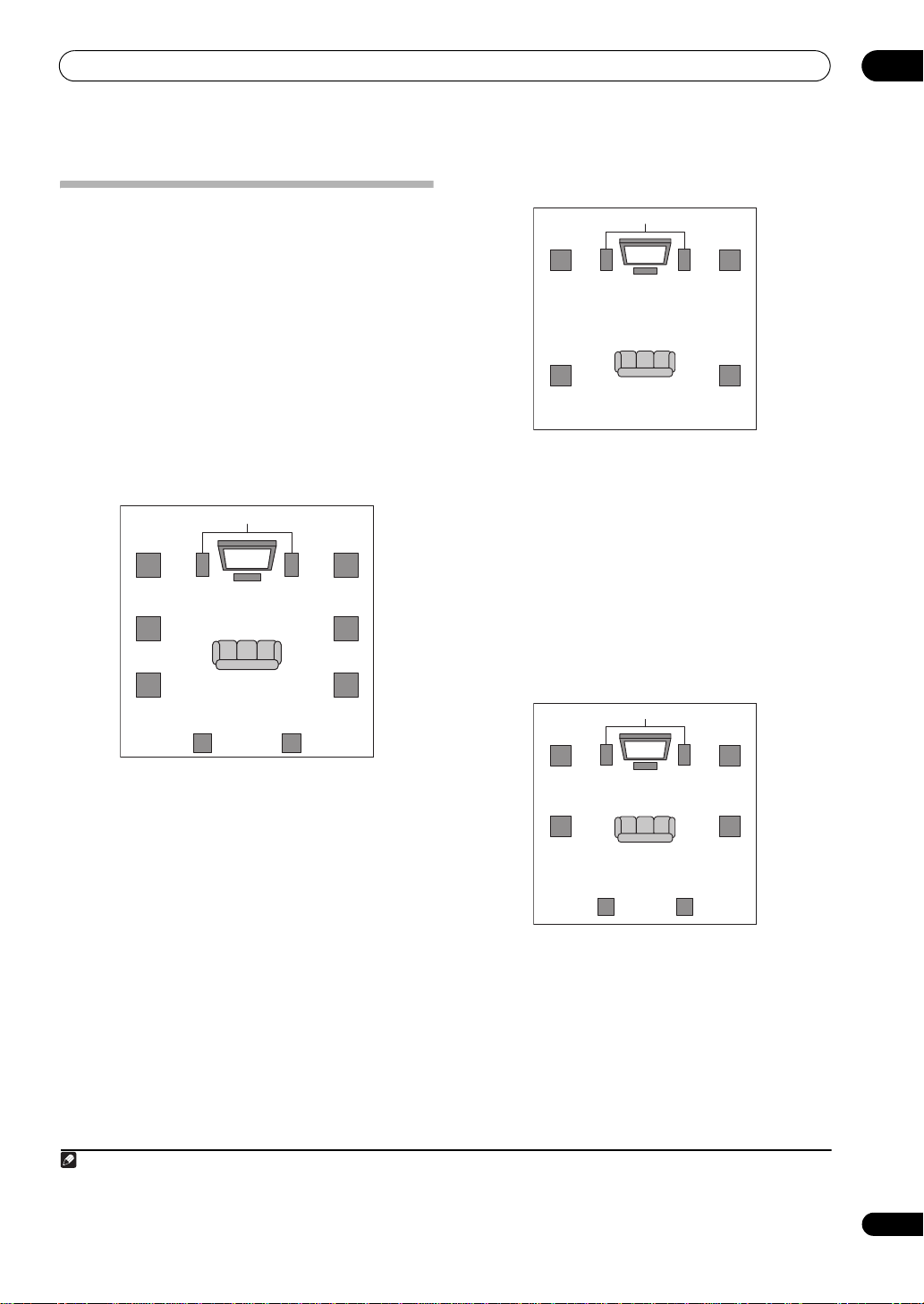
Selecting the speaker layout/usage
pattern
This amplifier is equipped with speaker terminals for 10
channels, and the speaker layout/usage pattern can be
selected to suit the user’s tastes. There are five speaker
layout/usage patterns, as described below. When using
this amplifier, be sure to select one of the five patterns
below before proceeding with the connections, settings
and playback operations.
Once you have decided on the speaker layout/usage
pattern, connect the speakers. Proceed to Positioning
and connecting the speakers on page 10.
Normal surround connections (default
setting)
Front
left (L)
Surround
left A (SL A)
1
Subwoofer
TV
Center (C)
right A (SR A)
Surround
Front
right (R)
5.2-channel Bi-amp connections
Subwoofer
TV
Front
left (L)*
Surround
left (SL)*
Center (C)*
*: bi-amp compatible speakers
Features: The front, center and surround channels are all
reproduced with high quality (bi-amp). Fewer speakers
are used than with other patterns and the maximum
number of channels is 5.2, but this pattern provides the
highest sound quality.
Speakers used: Total 5 bi-amp compatible speakers (2
front, 1 center, 2 surround)
Applicable listening rooms: Suited to all listening
rooms
Output Setup: All Ch Bi-Amp
Front
right (R)*
Surround
right (SR)*
02
Surround
left B (SL B)
Surround back
left (SBL)
Features: Connections can be made in the ways from 2
channels for stereo playback to 5.1 (the basic
Surround
right B (SR B)
Surround back
right (SBR)
7.2-channel front Bi-amp connections
Subwoofer
TV
Front
left (L)*
Center (C)*
Front
right (R)*
requirement for a home theater) or 7.1 channels, and on
this amplifier it is even possible to connect 9.2 channels.
With 9.1-channel (or 9.2-channel) connections, two
surround speakers are used on each of the left and right
sides, a speaker layout similar to that used in movie
theaters. Furthermore, the set can be used for both
Surround
left (SL)
Surround back
left (SBL)
Surround
right (SR)
Surround back
right (SBR)
movies and for high sound quality multi-channel music
sources such as SACD and DVD Audio discs.
Speakers used: Total maximum 9 (2 front, 1 center, 4
surround, 2 surround back)
Applicable listening rooms: The conditions in any
listening room can be accommodated, but when using
9.2 channels of speakers, ideally the space should be
large enough for the speakers.
Output Setup: Normal
Features: Provides up to 7.2-channel surround playback
with high quality sound (bi-amp) from the front and
center speakers.
Speakers used: Total 7 (2 front (bi-amp compatible), 1
center (bi-amp compatible), 2 surround, 2 surround
back)
Applicable listening rooms: Rooms with space to place
*: bi-amp compatible speakers
the surround back speakers behind or above the listening
position
Output Setup: Front Bi-Amp
Note
1 If you want to expand the system into a surround playback environment though there are currently only two speakers, or if you want to make bi-amp
connections though you do not have enough speaker cables, select the pattern you are thinking of trying. For either pattern, the optimum playback
environment can be achieved using Auto MCACC Setup, regardless of the number of speakers.
9
En
Page 10
02
Simple Home Theater Guide
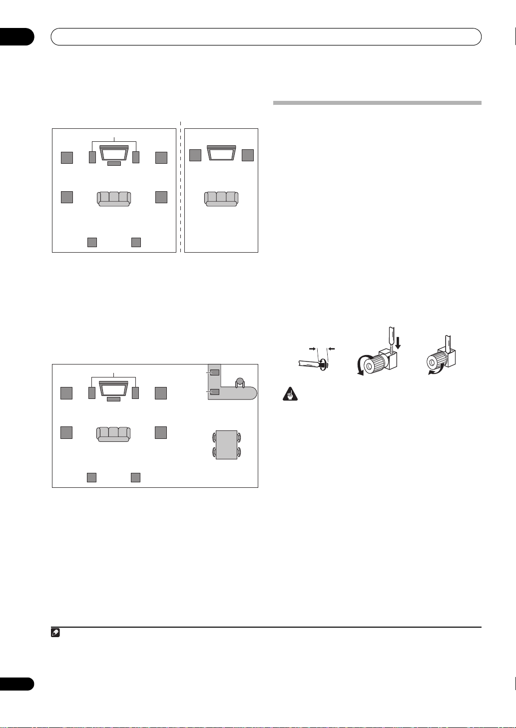
7.2-channel + Zone 2 connections
Main Zone
Subwoofer
TV
Front
left (L)
Surround
left (SL)
Surround back
left (SBL)
Center (C)
Surround back
right (SBR)
Front
right (R)
Surround
right (SR)
Features: Up to 7.2-channel playback in the main zone
with playback of a different device in Zone 2.
Speakers used: Total 9 (4 front, 1 center, 2 surround, 2
surround back)
Applicable listening rooms: When there are two
listening rooms
Output Setup: 7.2ch + ZONE 2
7.2-channel + speaker B connections
Front
left (L)
Zone 2
TV
Front
right (R)
Positioning and connecting the
speakers
For the speaker layout, refer to Selecting the speaker
layout/usage pattern on page 9. We recommend
positioning the speakers before connecting them. Use
one of the five connection examples below according to
the speaker layout/usage pattern selected.
commercially available speaker cords to make the
connections.
Bare wire connections
Make sure that the speaker cable you’re going to use is
properly prepared with about 10 mm of insulator stripped
from each wire, and the exposed wire strands twisted
together (fig. A).
To connect a terminal, unscrew the terminal a few turns
until there is enough space to insert the exposed wire
(fig. B). Once the wire is in position, tighten the terminal
until the wire is firmly clamped (fig. C).
(fig. A) (fig. B) (fig. C)
10 mm
1
Use
10
En
Front
left (L)
Subwoofer
TV
Center (C)
Front
right (R)
Speaker B
Speaker B
Important
• Before connecting the equipment, make sure that
the power is turned off and the power cords are
unplugged from the power outlets.
Surround
left (SL)
Surround back
left (SBL)
Surround
right (SR)
Surround back
right (SBR)
Features: Up to 7.2-channel playback in the normal
listening room plus stereo playback of the same sound in
another room (for example a kitchen). Furthermore,
different front speakers can be used for movies (multichannel playback) and music (stereo playback).
Speakers used: Total 9 (4 front, 1 center, 2 surround, 2
surround back)
Applicable listening rooms: When there is a main
listening room + a kitchen, etc.
Output Setup: 7.2ch + Speaker B
Note
1 • You can use speakers with a nominal impedance between 6 Ω and 16 Ω (or between 4 Ω and 16 Ω for the R1/L1 terminals).
• Each speaker connection on the amplifier comprises a positive (+) and negative (–) terminal. Make sure to match these up with the terminals on the
speakers themselves.
• Make sure that all the bare speaker wire is twisted together and inserted fully into the speaker terminal. If any of the bare speaker wire touches the back
panel it may cause the power to cut off as a safety measure.
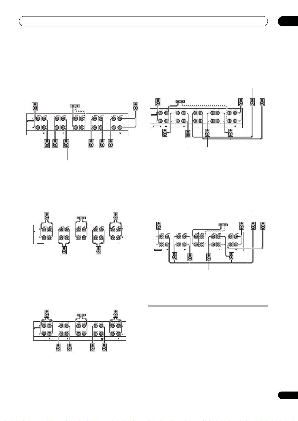
Page 11
Simple Home Theater Guide
02
Normal surround connections (default
setting)
When using only one surround back speaker, connect it
to the L4 (Single) terminals.
When only two surround speakers are connected,
connect them to the L2 (SL A) and R2 (SR A) terminals.
Front
right (R)
R1 R2
Normal
FRONT FRONTCENTER
LOW HIGH
FRONT
All ch Bi-Amp.
Surround
right A (SR A)
right B (SR B)
R3 R4 R5 L5
SUR-
SUR-
ROUND-A
ROUND-B
LOW HIGH
R
SURROUND
Surround
Surround back
right (SBR)
Center (C)
SURROUND
BACK
R
SURROUND
BACK
(Single)
LOW HIGH
CENTER
Surround back
left (SBL)
L4 L3 L2 L1
SURROUND-B
HIGH LOW
L
SURROUND
Surround
left B (SL B)
SURROUND-A
HIGH LOW
L
FRONT
Surround
left A (SL A)
Front
left (L)
If the center speaker is bi-amp compatible, make bi-amp
connections to achieve high quality sound.
5.2-channel Bi-amp connections
Make bi-amp connections using speakers that are all biamp compatible.
Front
right (R)
R1 R2
Normal
SUR-
FRONT FRONTCENTER
ROUND-A
LOW HIGH
R
FRONT
All ch Bi-Amp.
Surround
right (SR)
Center (C)
R3 R4 R5 L5
SUR-
SURROUND
ROUND-B
BACK
LOW HIGH
R
SURROUND
LOW HIGH
CENTER
Front
left (L)
L4 L3 L2 L1
SURROUND
SUR-
BACK
ROUND-B
(Single)
HIGH LOW
L
SURROUND
Surround
left (SL)
SURROUND-A
HIGH LOW
L
FRONT
7.2-channel + Zone 2 connections
When using only one surround back speaker, connect it
to the L4 (Single) terminals.
Front
right (R)
Front
right (R)
Normal
Center (C)
R1 R2
R3 R4 R5 L5
SUR-
SUR-
FRONT FRONTCENTER
ROUND-A
ROUND-B
LOW HIGH
LOW HIGH
R
SURROUND
FRONT
All ch Bi-Amp.
Surround
right (SR)
back right
SURROUND
BACK
R
Surround
(SBR)
LOW HIGH
CENTER
L4 L3 L2 L1
SURROUND
BACK
(Single)
HIGH LOW
SURROUND
Surround
back left
(SBL)
SURROUND-B
L
left (L)
SURROUND-A
HIGH LOW
L
FRONT
Surround
left (SL)
Front
Front
left (L)
If the center speaker is bi-amp compatible, make bi-amp
connections to achieve high quality sound.
7.2-channel + speaker B connections
When using only one surround back speaker, connect it
to the L4 (Single) terminals.
Front
right (R)
Front
right (R)
R1 R2
LOW HIGH
FRONT
R3 R4 R5 L5
SUR-
SUR-
ROUND-A
ROUND-B
LOW HIGH
R
Normal
FRONT FRONTCENTER
All ch Bi-Amp.
SURROUND
SURROUND
R
Front
Center (C)
L4 L3 L2 L1
SURROUND
LOW HIGH
CENTER
BACK
(Single)
HIGH LOW
SURROUND
BACK
left (L)
SUR-
SUR-
ROUND-A
ROUND-B
HIGH LOW
L
L
FRONT
Front
left (L)
7.2-channel front Bi-amp connections
For details about the bi-amp connections, see Bi-amping
your speakers on page 62.
When using only one surround back speaker, connect it
to the L4 (Single) terminals.
Make bi-amp connections using speakers that are biamp compatible for the front and center.
Front
right (R)
R1 R2
Normal
SUR-
FRONT FRONTCENTER
ROUND-A
LOW HIGH
R
FRONT
All ch Bi-Amp.
Surround
right (SR)
Center (C)
R3 R4 R5 L5
SUR-
SURROUND
ROUND-B
BACK
LOW HIGH
R
SURROUND
Surround
back right
(SBR)
LOW HIGH
CENTER
L4 L3 L2 L1
SURROUND
BACK
(Single)
HIGH LOW
SURROUND
Surround
back left
(SBL)
Front
left (L)
SUR-
SUR-
ROUND-A
ROUND-B
L
Surround
left (SL)
HIGH LOW
FRONT
L
Surround
right (SR)
Surround
back right
(SBR)
Surround
back left
(SBL)
Surround
left (SL)
If the center speaker is bi-amp compatible, make bi-amp
connections to achieve high quality sound.
Automatically setting up for surround
sound (MCACC & Full Band Phase
Control)
The Auto MCACC Setup measures the acoustic
characteristics of your listening area, taking into account
ambient noise, speaker size and distance, and tests for
both channel delay and channel level. After you have set
up the microphone provided with your system, the
amplifier uses the information from a series of test tones
to optimize the speaker settings and equalization for your
particular room, and also to calibrate the frequencyphase characteristics of the speakers connected.
11
En
Page 12
02
Simple Home Theater Guide
Make sure you do this before moving on to Playing a
source on page 13.
Important
• Make sure the microphone and speakers are not
moved during the Auto MCACC Setup.
• Using the Auto MCACC Setup will overwrite any
existing settings for the MCACC preset you select.
• Before using the Auto MCACC Setup, the
headphones should be disconnected and the iPod or
HOME MEDIA GALLERY function should not be
selected as an input source.
Caution
• The test tones used in the Auto MCACC Setup are
output at high volume.
SOURCE
SOURCE
AMP
TV AMP
AV AMPLIFIER
DVD
DVR1
HOME MEDIA
GALLERY
TUNER
MAIN
ZONE2 3
MULTI
OPERATION
BD TV SAT
VIDEO1
DVR2
CD
SACD
iPod HDMI
PHONO
INPUT SELECT
SOURCE
VIDEO2
CD-R
TV
CH
VOL
TV CONTROL
INPUT MUTE MUTE
AUDIO
PARAMETER
TOP MENU
ENTER
ENTER
SETUP
SETUP
SETUP
VOL
VIDEO
PARAMETER
MENU
RETURN
RETURN
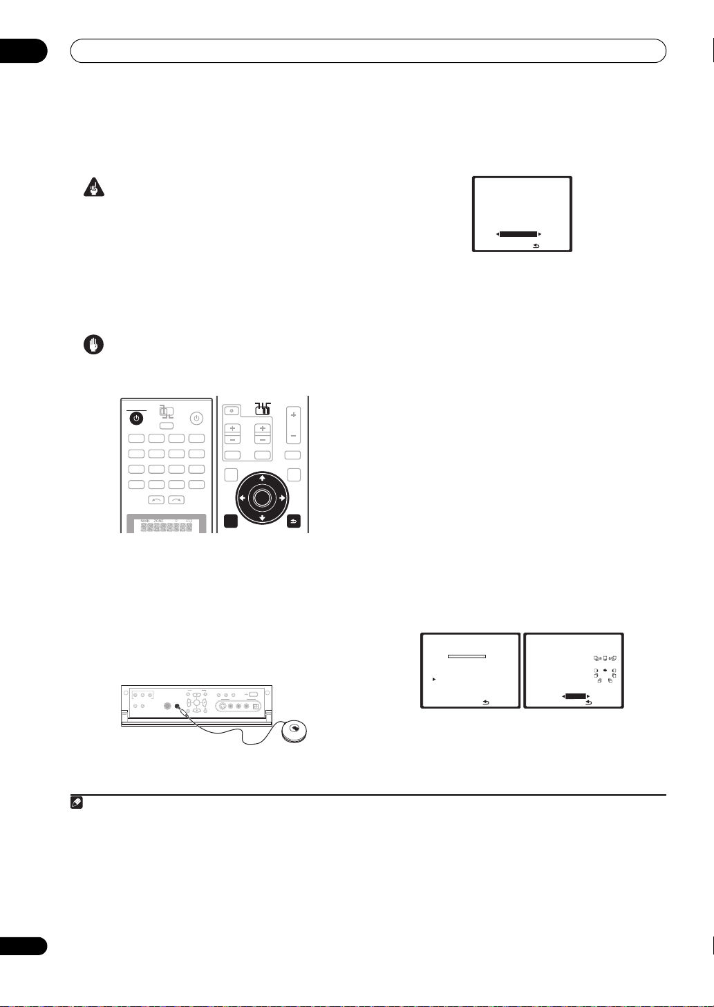
1 Switch on the amplifier and your TV.
2 Connect the microphone to the
MCACC SETUP MIC
jack on the front panel.
Place the microphone so that it’s about ear level at your
normal listening position (use a tripod if possible). Make
sure there are no obstacles between the speakers and
the microphone.
• Push down on the lower portion of the front panel
door to access the MCACC SETUP MIC jack:
LCD
ZONE2 ZONE3
CTRL
MULTI-ZONE CONTROL
SPEAKERS AUTO SURROUND
/STREAM DIRECT
PARAMETER
AUDIO VIDEO
ENTER
MCACC
MCACC
PHONES
SETUP MIC
SETUP MIC
SETUP
RETURN
USB
VIEW
STATUS
DIMMER
VIDEO/GAME 2 INPUT
DIGITAL INS-VIDEO VIDEO L R
AUDIO
The Auto MCACC display appears once the microphone
is connected.
3 Make sure ‘
preset
1
Normal
3
, then select
DVD/LD
1. Auto MCACC
Output Setup
[ Normal ]
Save SYMMETRY to
[ M1. MEMORY 1 ]
START
ENTER:Start :Cancel
-
55.0
dB
’ is selected,2 select an MCACC
4
START
.
4 Follow the instructions on-screen.
Make sure the microphone is connected, and if you’re
using a subwoofer, make sure it is switched on and set to
a comfortable volume level.
5 Wait for the test tones to finish, then confirm the
speaker configuration in the OSD.
A progress report is displayed on-screen while the
amplifier outputs test tones to determine the speakers
present in your setup. Try to be as quiet as possible while
it’s doing this.
5
If no operations are performed for 10 seconds while the
speaker configuration check screen is being displayed,
the Auto MCACC Setup will resume automatically. In this
case, you don’t need to select ‘OK’ and press ENTER in
step 6.
• With error messages (such as Too much ambient
noise! or Check Microphone) select RETRY after
checking for ambient noise (see Problems when
using the Auto MCACC Setup on page 13) and
verifying the mic connection. If there doesn’t seem to
be a problem, you can simply select GO NEXT and
continue.
DVD/LD 0.0
1. Auto MCACC
Now Analyzing… ( 2/10)
Environment Check
Ambient Noise [ OK ]
Microphone [ ]
Speaker YES/NO [ ]
dB
:Cancel
DVD/LD 0.0
1. Auto MCACC
CHECK
Front [ YES ]
Center [ YES ]
Surr A [ YES ]
Surr B [ YES ]
SB [ YESx2 ]
SW [ YESx2 ]
OK
10:Next
:Cancel
The configuration shown on-screen should reflect the
actual speakers you have.
dB
12
En
Note
1 • You can’t use the System Setup menu in either the main or sub zone when the iPod or HOME MEDIA GALLAERY input source is selected. When you
set ZONE 2, ZONE 3 or ZONE 2&3 to ON (page 66), you can’t use the System Setup menu.
• If you cancel the Auto MCACC Setup, or leave an error message for over three minutes, the screen saver will appear.
2 • The setting you should select differs according to the selected speaker layout/usage method (for example if you are planning to make bi-amp
connections, to set up another speaker system, etc.). For details see Selecting the speaker layout/usage pattern on page 9 and Speaker output setting on
page 43.
• If you have THX-certified speakers, select CUSTOM and choose YES for the THX Speaker setting.
3 The six MCACC presets are used for storing surround sound settings for different listening positions. Simply choose an unused preset for now (you can
rename it later in Data Management on page 50).
4 Note that correction curves are saved only when set to SYMMETRY. Select CUSTOM to save other correction curves (such as ALL CH ADJUST and
FRONT ALIGN). See Automatic MCACC (Expert) on page 40 for more on this.
5 Do not adjust the volume during the test tones. This may result in incorrect speaker settings.
Page 13

Simple Home Theater Guide
If you see an error message (ERR) in the right side
column (or the speaker configuration displayed isn’t
correct), there may be a problem with the speaker
connection. If selecting RETRY doesn’t work, turn off the
power and check the speaker connections. If there
doesn’t seem to be a problem, you can simply use /
to select the speaker and / to change the setting
(and number for surround back) and continue.
6 Make sure ‘OK’ is selected, then press
A progress report is displayed on-screen while the
amplifier outputs more test tones to determine the
optimum amplifier settings for Channel Level, Speaker
Distance, Standing Wave, Acoustic Cal EQ and Full Band
Phase Control.
Again, try to be as quiet as possible while this is
happening. It may take 3 to 10 minutes.
7 The Auto MCACC Setup has finished! Press
to go back to the System Setup menu.
Be sure to disconnect the microphone from this amplifier
upon completion of the Auto MCACC setup.
The settings made in the Auto MCACC Setup should give
you excellent surround sound from your system, but it is
also possible to adjust these settings manually using the
System Setup menu (starting on page 40).
Problems when using the Auto MCACC Setup
If the room environment is not optimal for the Auto
MCACC Setup (too much background noise, echo off the
walls, obstacles blocking the speakers from the
microphone) the final settings may be incorrect. Check
for household appliances (air conditioner, fridge, fan,
etc.), that may be affecting the environment and switch
them off if necessary. If there are any instructions
showing in the front LCD display, please follow them.
• Some older TVs may interfere with the operation of
the microphone. If this seems to be happening,
switch off the TV when doing the Auto MCACC Setup.
1
ENTER
2
.
RETURN
Playing a source
Here are the basic instructions for playing a source (such
as a DVD disc) with your home theater system.
MAIN
AV AMPLIFIER
AV AMPLIFIER
DVD
DVD
DVR1
DVR1 DVR2
HOME MEDIA
HOME MEDIA
GALLERY
GALLERY
TUNER
TUNER
ZONE2 3
MULTI
OPERATION
BD TV SAT
BD TV SAT
VIDEO1
VIDEO1
DVR2
CD
SACD
CD
SACD
iPod HDMI
PHONO
iPod HDMI
PHONO
INPUT SELECT
SOURCE
VIDEO2
VIDEO2
CD-R
CD-R
SOURCE
TV AMP
CH
VOL
TV CONTROL
INPUT MUTE MUTE
AUDIO
PARAMETER
1 Switch on your system components and amplifier.
Start by switching on the playback component (for
example a DVD player), your TV
have one), then the amplifier (press AV AMPLIFIER).
3
• Make sure the setup mic is disconnected.
2 Select the input source you want to play.
You can use the input source buttons on the remote
control, INPUT SELECT, or the front panel INPUT
SELECTOR dial.
3Press
DIRECT
playback of the source.
4
AUTO/DIRECT (AUTO SURROUND/STREAM
) to select ‘
AUTO SURROUND
5
If you’re playing a Dolby Digital or DTS surround sound
DVD disc, you should hear surround sound. If you are
playing a stereo source, you will only hear sound from the
front left/right speakers in the default listening mode.
•See also Listening to your system on page 34 for
information on different ways of listening to sources.
It is possible to check on the LCD whether or not multichannel playback is being performed properly.
When using a surround back speaker, Dolby Digital EX
is displayed when playing Dolby Digital signals, and
DTS+Neo:6 is displayed when playing DTS 5.1-channel
signals.
When not using a surround back speaker, Dolby Digital
is displayed when playing Dolby Digital signals.
SETUP
STATUS
CH LEVEL
THX
STEREO/
AUTO/
AUTO/
F.S.SURR
DIRECT
DIRECT
VOL
VOL
SIGNAL SEL SLEEP AUDIODIMMER
SR+ SBch PHASE iPod CTRL
VIDEO
PARAMETER
and subwoofer (if you
’ and start
02
RETURN
STANDARD ADV SURR
DISP
Note
1 You can also choose to view the settings from the MCACC Data Check screen. See Automatic MCACC (Expert) on page 40 for more on this.
2 • Depending on the characteristics of your room, sometimes identical speakers with cone sizes of around 12 cm end up with different size settings. You
can correct the setting manually using the Manual speaker setup on page 52.
• The subwoofer distance setting may be farther than the actual distance from the listening position. This setting should be accurate (taking delay and
room characteristics into account) and generally does not need to be changed.
• If Auto MCACC Setup measurement results are incorrect due to the interaction of the speakers and viewing environment, we recommend adjusting
the settings manually.
3 Make sure that the TV’s video input is set to this amplifier (for example, if you connected this amplifier to the VIDEO 1 jacks on your TV, make sure that
the VIDEO 1 input is now selected).
4 If you need to manually switch the input signal type press SIGNAL SEL (page 37).
5 • You may need to check the digital audio output settings on your DVD player or digital satellite receiver. It should be set to output Dolby Digital, DTS and
88.2 kHz / 96 kHz PCM (2 channel) audio, and if there is an MPEG audio option, set this to convert the MPEG audio to PCM.
• Depending on your DVD player or source discs, you may only get digital 2 channel stereo and analog sound. In this case, the amplifier must be set to
a multichannel listening mode (see Listening in surround sound on page 34 if you need to do this) if you want multichannel surround sound.
13
En
Page 14
02
Simple Home Theater Guide
14
En
For other details, see Listening modes with different input
signal formats on page 141. If the display does not
correspond to the input signal and listening mode, check
the connections and settings.
Phase Control ON
Front speaker
Listening
position
4 Use the volume control to adjust the volume level.
Turn down the volume of your TV so that all sound is
coming from the speakers connected to this amplifier.
Better sound using Phase Control and
Full Band Phase Control
This amplifier is equipped with the two types of functions
that correct phase distortion and group delay: Phase
Control and Full Band Phase Control. Activating Full
Band Phase Control is strongly recommended because it
also involves the effects of Phase Control. For details on
each of these two features, refer to the following
explanations.
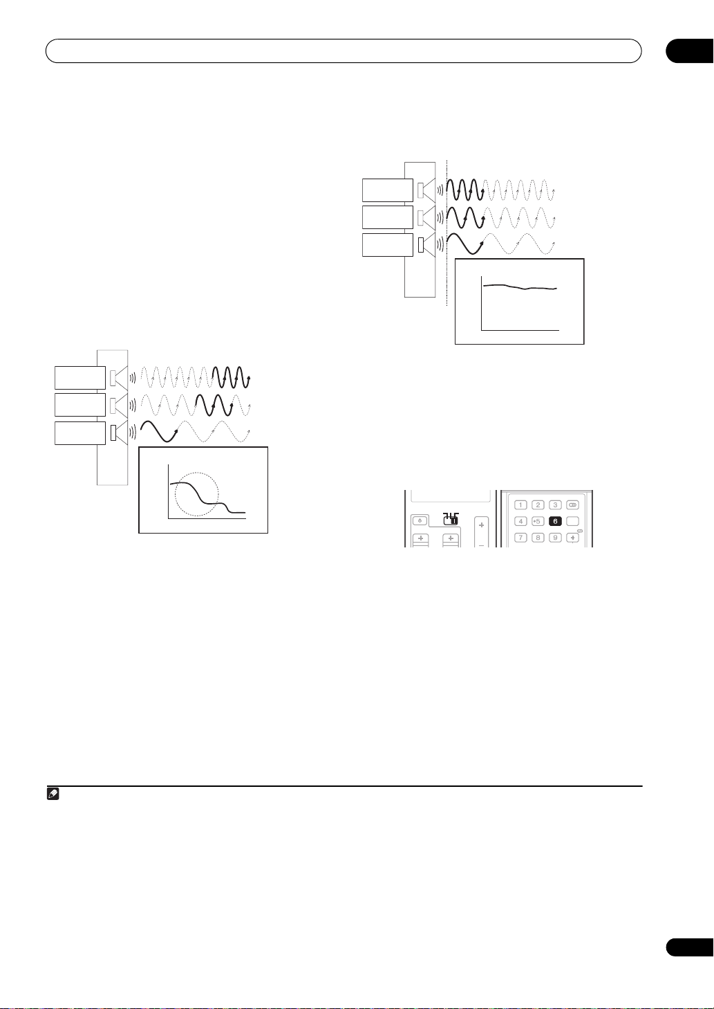
Using Phase Control
During multichannel playback, LFE (Low-Frequency
Sound
source
Subwoofer
• Rhythms with crystal-like clarity
• Bass sound with no loss of depth
• Sound of musical instruments with superb reality
Phase Control technology provides coherent sound
reproduction through the use of phase matching
optimal sound image at your listening position. The
default setting is on and we recommend leaving Phase
Control switched on for all sound sources.
SOURCE
SOURCE
TV AMP
TV AMP
VOLCH
SIGNAL SEL SLEEP AUDIODIMMER
VOL
SR+
SBch PHASE iPod CTRL
A.ATT GENRE
Original sound
preserved with no
loss of clarity
1
PHASE
DISP
HDMI OUT
for an
Effects) signals as well as low-frequency signals in each
channel are assigned to the subwoofer or other the
subwoofer and the most appropriate speaker. At least in
theory, however, this type of processing involves a group
delay that varies with frequency, resulting in phase
• Set the operation selector switch to AMP, then
press PHASE (PHASE CONTROL) to select PHASE
CONTROL.
The PHASE CONTROL indicator on the front panel lights.
distortion where the low-frequency sound is delayed or
muffled by the conflict with other channels. With the
Phase Control mode switched on, this amplifier can
reproduce powerful bass sound without deteriorating the
quality of the original sound (see illustration below).
Phase Control OFF
Front speaker
Listening
position
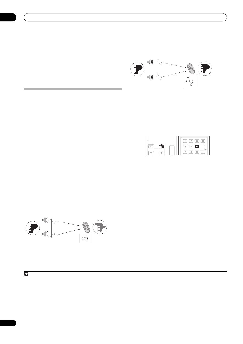
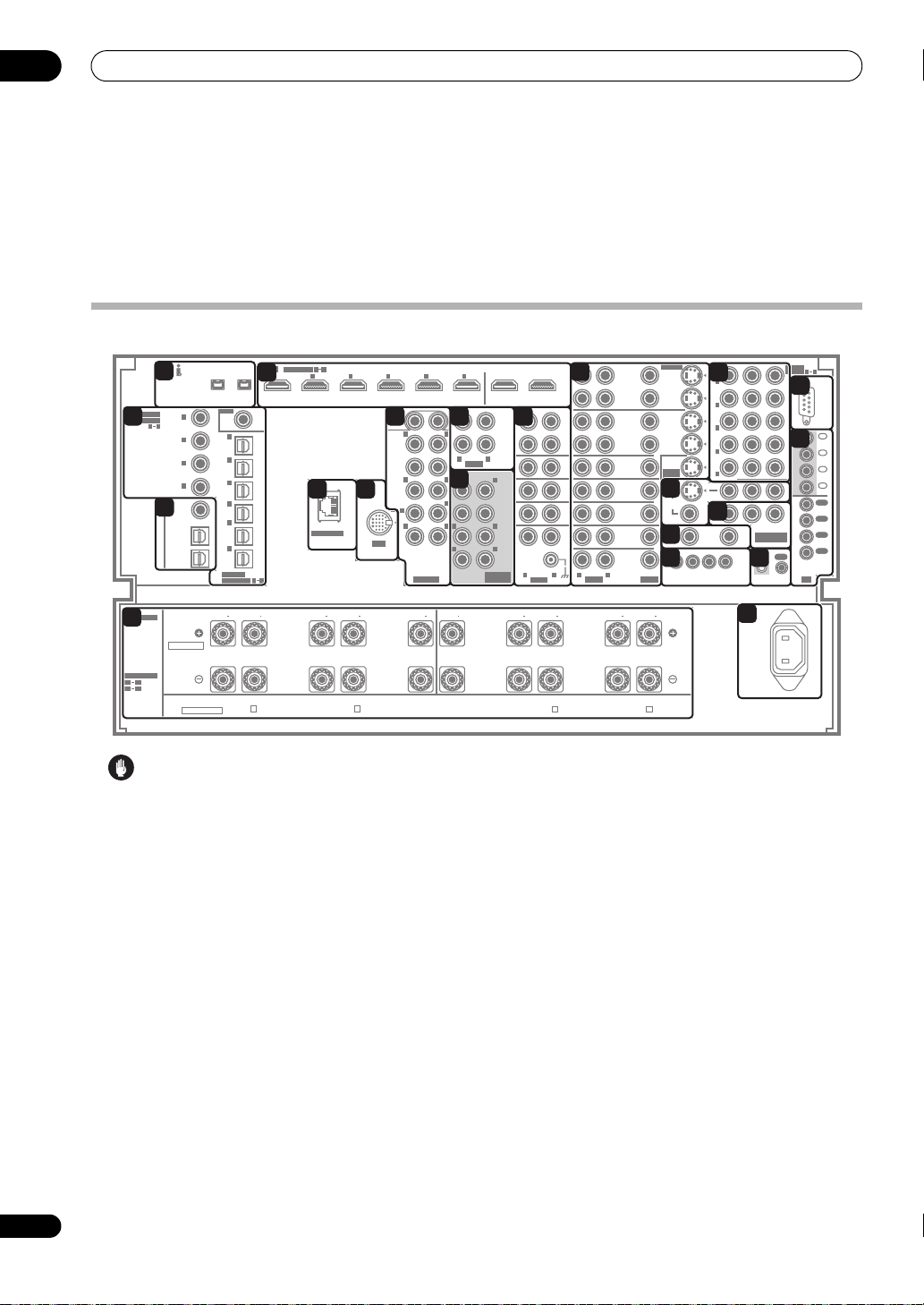
Using Full Band Phase Control
The Full Band Phase Control feature calibrates the
frequency-phase characteristics of the speakers
connected.
Standard speakers designed exclusively for audio use
generally reproduce sound with the divided frequency
bands output from a speaker system consisting of
multiple speakers (in case of typical 3-way speakers, for
instance, the tweeter, the squawker (midrange), and the
woofer output sound in the high-, middle-, and low-
frequency ranges, respectively). Though these speakers
Sound
source
Subwoofer
Sound muffled due
to a delay in time
are designed to flatten the frequency-amplitude
characteristics across wide ranges, there are cases
where the group delay characteristics are not effectively
• Rhythms blurred and difficult to hear
• Bass sound with loss of depth
• Sound of musical instruments with no reality
Note
1 • Phase matching is a very important factor in achieving proper sound reproduction. If two waveforms are ‘in phase’, they crest and trough together,
resulting in increased amplitude, clarity and presence of the sound signal. If a crest of a wave meets a trough (as shown in the upper section of the diagram
above), then the sound will be ‘out of phase’ and an unreliable sound image will be produced.
• The PHASE CONTROL feature is available even when the headphones are plugged in.
• If your subwoofer has a phase control switch, set it to the plus (+) sign (or 0°). However, the effect you can actually feel when PHASE CONTROL is set
to ON on this amplifier depends on the type of your subwoofer. Set your subwoofer to maximize the effect. It is also recommended you try changing the
orientation or the place of your subwoofer.
• Set the built-in lowpass filter switch of your subwoofer to OFF. If this cannot be done on your subwoofer, set the cutoff frequency to a higher value.
• If the speaker distance is not properly set, you may not have a maximized PHASE CONTROL effect.
• The PHASE CONTROL mode cannot be set to ON in the following cases:
– When the PURE DIRECT mode is switched on.
– When the HDMI audio output parameter is set to THROUGH in Setting the Audio options on page 99.
flattened. This phase distortion of the speakers
subsequently causes group delay (the delay of low-
frequency sound against high-frequency sound) during
audio signal playback.
Page 15
Simple Home Theater Guide
02
This amplifier analyzes the frequency-phase
characteristics of the speakers by calibrating test signals
output from the speakers with the supplied microphone,
therefore flattening the analyzed frequency-phase
characteristics during audio signal playback
1
– the same
correction is made for a pair of left and right speakers.
This correction minimizes group delay between the
ranges of a speaker and improves the frequency-phase
characteristics across all ranges.
Furthermore, the enhanced frequency-phase
characteristics between channels ensure better
surround sound integration for multichannel setting.
2
Full Band Phase Control OFF
Tweeter
Midrange
Woofer
Group Delay Characteristics
ms
Hz
Sound in the middle- and low-frequency ranges is
delayed against the high-frequency sound due to group
delay.
Full Band Phase Control ON
Tweeter
Midrange
Woofer
Group Delay Characteristics
ms
Hz
With the phase distortion corrected, the frequency-phase
characteristics are improved across all ranges.
• Sound with live dynamics
• Sound of musical instruments with superb reality
• Sound so accurately reproduced that you can even
hear the lip movement of the singer
• Speech heard with no loss of clarity
• Surround sound with excellent integration
VOL
SIGNAL SEL SLEEP AUDIODIMMER
SR+
SBch PHASE iPod CTRL
PHASE
HDMI OUT
A.ATT GENRE
DISP
SOURCE
SOURCE
TV AMP
TV AMP
VOLCH
• Set the operation selector switch to AMP, then
press PHASE (PHASE CONTROL) to select
FULLBAND PHASE.
3
Both the Phase Control and Full Band Phase Control
functions are switched on. The PHASE CONTROL
indicator lights on the front LCD display.
Note
1 To calibrate and analyze the frequency-phase characteristics of the speakers, follow the procedures in Auto MCACC Setup (see Automatically setting up
for surround sound (MCACC & Full Band Phase Control) on page 11) or FULL BAND PHASE CTRL in the System Setup (see Full Band Phase Control on
page 49). Select ALL when you perform the Auto MCACC Setup with CUSTOM. Upon calibration of the frequency-phase characteristics of the speakers,
the FULL BAND PHASE CTRL feature is automatically switched on. Note that FULLBAND PHASE cannot be selected unless the frequency-phase
characteristics of the speakers are calibrated.
2 The original characteristics of group delay of the speakers calibrated and the targeted characteristics after correction can be displayed graphically in the
OSD (see Full Band Phase Control on pa ge 49). A lso, w hen yo ur PC i s conn ected to this amplifier, the original characteristics of group delay of the speakers
calibrated and the corrected characteristics of group delay can be displayed in 3-dimension on your PC (see Advanced MCACC output using your PC on
page 70).
3The FULL BAND PHASE CTRL mode cannot be set to ON in the following cases:
– When headphones are plugged in.
– When the PURE DIRECT mode is switched on.
– When the HDMI audio output parameter is set to THROUGH in Setting the Audio options on page 99.
15
En
Page 16
03
Connecting your equipment
Chapter 3:
Connecting your equipment
This amplifier provides you with many connection possibilities, but it doesn’t have to be difficult. This page explains
the kinds of components you can connect to make up your home theater system.
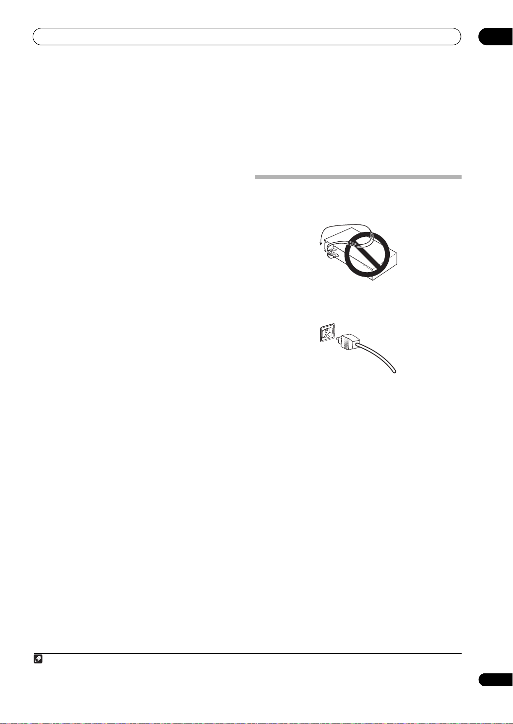
Rear panel
YP
15
IN
(DVD/LD)
IN
(BD)
IN
(VIDEO/
GAME
1)
IN
(DVR/VCR 1)
IN
(DVR/VCR 2)
ZONE2
OUT
16
BPR
ASSIGN-
5
1
COMPONENT
VIDEO
CONTROL
IN
17
ABLE
18
RS232C
IN
1
19
IN
2
IN
3
IN
4
OUT
1
OUT
2
OUT
3
OUT
4
OUT
IR
1
2
3
4
5
)
ASSIGNABLE
2
COAXIAL
ASSIGNABLE
61
5
LAN (10/100)
OUT1
6
(HDMI CTRL)
12
ZONE2
AUDIO
L
L
FRONT
CENTER
LR
SURROUND
LR
SURROUND
BACK
MULTI CH
IN
108
OUT
ZONE3
OUT
7
SUB
WOOFER
FRONT
CENTER
SURROUND
6
IN
iPod
SURROUND
BACK
R
EXTRA
L
R
12
R
LR
R
9
(
)
Single
SUB W.
L
R
L
PRE OUT
11
OUT2
REC
SEL
OUT
CD-R/
TAPE /
MD
IN
CD
IN
SACD
IN
TUNER
IN
IN
PHONO
LR
LR
AUDIO
(AUDIO)
1
1
IN
(
)
DVD/LD
1 4
2
IN
(BD)
3
IN
(CD)
4
IN
(SACD)
ZONE2
3
OUT
ZONE3
/SOURCE
OUT
SOURCE
OUT
HDMI
IN1IN2IN3IN4IN5IN
4
S400S400
RF IN
2
(
)
For LD
1
IN
(TV)
2
IN
(SAT)
3
IN
(DVR/
VCR 1)
4
IN
(DVR/
VCR 2)
5
IN
(VIDEO/
GAME
1)
6
IN
(CD-R/
TAPE/
MD)
OPTICAL
1 6
ASSIGNABLE
REC SEL
DVR/
VCR 1
REC SEL
DVD/LD
SAT
VIDEO/
GAME 1
OUT
IN
OUT
IN
IN
BD
IN
TV
IN
IN
IN
DVR/
VCR 2
S-VIDEO
REC SEL
REC SEL
ASSIGNABLE
12
13
14
VIDEOAUDIO
OUT
IN
OUT
IN
IN
(DVD/LD)
MONITOR
OUT
VIDEO
ZONE3
ZONE2
OUT
OUT
12 V TRIGGER
1 2 34
(
DC OUT 12V TOT AL 250 mA MAX
SPEAKERS
20
SELECTABLE
SELECTABLE
R1 R5
L1
L5
SEE
INSTRUCTION
MANUAL
VOIR LE MODE
D'EMPLOI
R1
4Ω16ΩR26Ω16Ω
Normal
FRONT FRONTCENTER
LOW HIGH
R
FRONT
All ch Bi-Amp.
SURROUND-A
SURROUND-B
R3
6Ω16ΩR46Ω16Ω
LOW HIGH
SURROUND
SURROUND
BACK
R
R5
6Ω16ΩL56Ω16Ω
LOW HIGH
CENTER
Caution
• Before making or changing the connections, switch
off the power and disconnect the power cord from the
power outlet. Plugging in should be the final step.
1 S-400 i.LINK connectors (x2)
Use to connect other i.LINK audio devices for highresolution, multichannel digital audio input/output.
See Using the i.LINK interface on page 58.
2 Optical and coaxial digital audio inputs (x10)
Use for digital audio sources, including DVD players/
recorders, digital satellite receivers, CD players, etc.
There’s also an RF IN jack for connection to an LD player
with a 2 RF output.
See also The Input Setup menu on page 94 to assign
the inputs.
3 Optical and coaxial digital audio outputs (x3)
Use for recording to a CD or MiniDisc recorder.
See Connecting digital audio sources on page 25.
These jacks are also used for MULTI-ZONE connections.
See MULTI-ZONE listening on page 64.
21
AC IN
SURROUND
BACK
(Single)
L4
6Ω16ΩL36Ω16Ω
HIGH LOW
SURROUND
SURROUND-B
L
SURROUND-A
L2
6Ω16Ω
HIGH LOW
FRONT
L1
4Ω16Ω
L
4 HDMI connectors (x8)
Multiple inputs and two outputs for high-quality audio/
video connection to compatible HDMI devices.
See Connecting using HDMI on page 18.
See Switching the HDMI output on page 103.
5 LAN (10/100) terminal
See Playback with HOME MEDIA GALLERY inputs on
page 71.
6 iPod input terminal
Use to connect your Apple iPod as an audio or video
source.
See Connecting an iPod on page 56.
7 Multichannel pre-amplifier outputs
Use to connect separate amplifiers for front, center,
surround, surround back and subwoofer channels.
See Connecting additional amplifiers on page 63 (see
also Installing your speaker system on page 27 for
powered subwoofer connection).
8 MULTI-ZONE audio outputs
Use to connect a second or third amplifier in a separate
room.
See MULTI-ZONE listening on page 64.
16
En
Page 17
Connecting your equipment
03
9 Multichannel analog audio inputs
7.1 channel inputs for connection to a DVD player with
multichannel analog outputs.
See Connecting the multichannel analog inputs on
page 60.
10 Stereo analog audio source inputs/(outputs) (x5)
Use for connection to audio sources such as CD players,
tape decks, turntables, etc.
See Connecting analog audio sources on page 26.
11 Audio/video source inputs/(outputs) (x7)
Use for connection to audio/visual sources, such as DVD
players/recorders, VCRs, etc. Each set of inputs has jacks
for composite video, S-Video
See Connecting a DVD/HDD recorder, VCR and other
video sources on page 23.
12 Composite, S-Video and Component monitor
outputs
Use to connect monitors and TVs.
See Connecting your TV and DVD player on page 20.
See Using the component video jacks on page 24.
13 MULTI-ZONE video outputs
Use to connect monitors or TVs in a separate room.
See MULTI-ZONE listening on page 64.
14 12 V trigger jacks
Use to switch components in your system on and off
according to the input function of the amplifier.
See Switching components on and off using the 12
volt trigger on page 67.
15 Component video inputs (x5)
Use the inputs to connect any video source that has
component video output, such as a DVD recorder.
See Using the component video jacks on page 24.
16 MULTI-ZONE component video output
Use to connect monitors or TVs in a separate room.
See MULTI-ZONE listening on page 64.
17 Control input/output
Use to connect other Pioneer components so that you
can control all your equipment from a single IR remote
sensor.
See Operating other Pioneer components with this
unit’s sensor on page 111.
18 RS-232C connector
Use for connection to a PC for graphical output when
using Advanced MCACC or Full Band Phase Control.
See Connecting a PC for Advanced MCACC output on
page 69.
19 Remote inputs/outputs (MULTI-ZONE and source)
Use for connection to an external remote control sensor
for use in a MULTI-ZONE setup, for example.
See Connecting an IR receiver on page 67.
Note
1 You must assign the input source to the S-Video input to which you’ve connected your video component (see The Input Setup menu on page 94).
1
and stereo analog audio.
(total 50 mA max.)
(x4)
20 Speaker terminals
Use for connection to the main front, center, surround
and surround back speakers.
See Installing your speaker system on page 27.
21 AC power inlet
Connect the supplied power cord here.
When making cable connections
• To avoid hum, do not lay connected cables over the
top of the amplifier.
• When connecting optical cables, be careful when
inserting the plug not to damage the shutter
protecting the optical socket.
• When storing optical cable, coil loosely. The cable
may be damaged if bent around sharp corners.
17
En
Page 18
03
Connecting your equipment
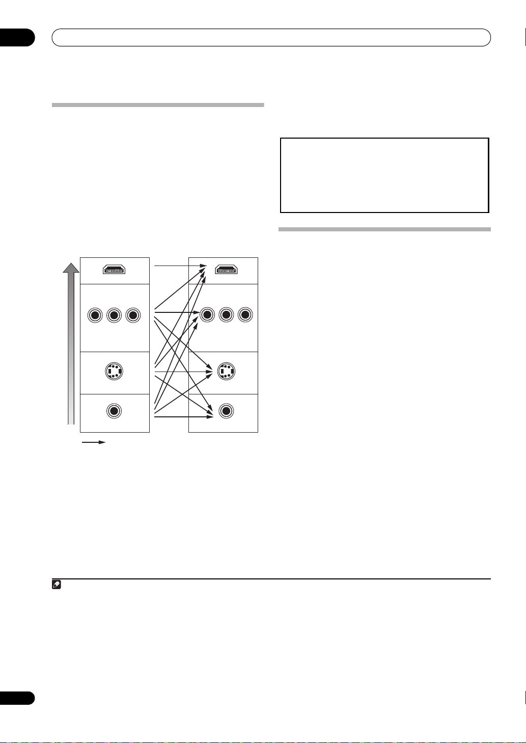
About the video converter
The video converter ensures that all video sources are
output through all of the MONITOR VIDEO OUT jacks.
The only exception is HDMI: since this resolution cannot
be downsampled, you must connect your monitor/TV to
the amplifier’s HDMI video outputs when connecting this
video source.
If several video components are assigned to the same
input function (see The Input Setup menu on page 94),
the converter gives priority to HDMI, component, SVideo, then composite (in that order).
High picture quality
1
Terminal for connection
with source device
HDMI IN
COMPONENT VIDEO IN
S-VIDEO IN
VIDEO IN
Video signals can be output
Terminal for connection
with TV monitor
HDMI OUT
COMPONENT VIDEO
MONITOR OUT
S-VIDEO
MONITOR OUT
VIDEO
MONITOR OUT
• For optimal video performance, THX recommends
switching Digital Video Conversion (in Setting the
Video options on page 101) OFF.
This product incorporates copyright protection technology that is
protected by method claims of certain U.S. patents and other
intellectual property rights owned by Macrovision Corporation and
other rights owners. Use of this copyright protection technology
must be authorized by Macrovision Corporation, and is intended
for home and other limited viewing uses only unless otherwise
authorized by Macrovision Corporation. Reverse engineering or
disassembly is prohibited.
Connecting using HDMI
If you have an HDMI or DVI (with HDCP) equipped
component, you can connect it to this amplifier using a
commercially available HDMI cable.
The HDMI connection transfers uncompressed digital
video, as well as almost every kind of digital audio that the
connected component is compatible with, including
DVD-Video, DVD-Audio, SACD, Dolby Digital Plus, Dolby
TrueHD, DTS-HD Master Audio (see below for
limitations), Video CD/Super VCD, CD and MP3. See
About the video converter above for more on HDMI
compatibility.
When connecting to an HDMI/DVI-compatible monitor or
a plasma television using the HDMI OUT 2 terminal,
switch the HDMI output setting to HDMI OUT2. See
Switching the HDMI output on page 103.
2
18
En
Note
1 • If the video signal does not appear on your TV or plasma television, try adjusting the resolution settings on your component or display. Note that some
components (such as video game units) have resolutions that may not be converted. In this case, try switching Digital Video Conversion (in Setting the Video
options on page 101) OFF.
• The ZONE 2 video input can also be converted. For details, see ZONE Video Setup on page 96.
2 • An HDMI connection can only be made with DVI-equipped components compatible with both DVI and High Bandwidth Digital Content Protection
(HDCP). If you choose to connect to a DVI connector, you will need a separate adaptor (DVIHDMI) to do so. A DVI connection, however, does not support
audio signals. Consult your local audio dealer for more information.
• If you connect a component that is not compatible with HDCP, a HDCP ERROR message is displayed on the front LCD display. Some components that
are compatible with HDCP still cause this message to be displayed, but so long as there is no problem with displaying video this is not a malfunction.
• This amplifier has been designed to be compliant with HDMI (High Definition Multimedia Interface) Version 1.3a. Depending on the component you
have connected, using a DVI connection may result in unreliable signal transfers.
• This amplifier supports SACD, Dolby Digital Plus, Dolby TrueHD and DTS-HD Master Audio. To take advantage of these formats, however, make sure
that the component connected to this amplifier also supports the corresponding format.
Page 19
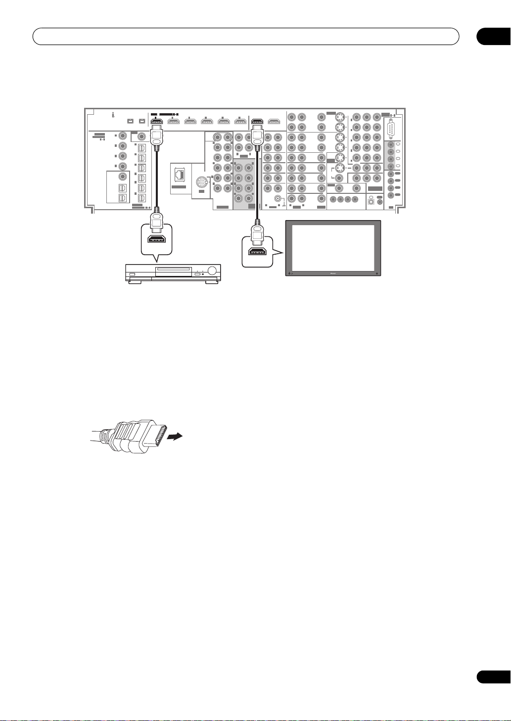
Connecting your equipment
03
SC-LX90
61
61
HDMI
HDMI
ASSIGNABLE
ASSIGNABLE
1
IN1IN2IN3IN4IN5IN
IN
S400S400
RF IN
2
(
)
For LD
1
IN
(TV)
2
IN
(SAT)
3
IN
4
IN
(DVR/
VCR 2)
5
IN
GAME
IN
(CD-R/
TAPE/
OPTICAL
ASSIGNABLE
1)
6
MD)
LAN (10/100)
1 6
12
SUB
WOOFER
L
R
FRONT
12
CENTER
LR
SURROUND
(
)
Single
SURROUND
L
BACK
R
IN
R
iPod
L
EXTRA
PRE OUT
COAXIAL
ASSIGNABLE
(AUDIO)
1
IN
(
)
DVD/LD
1 4
2
IN
(BD)
3
IN
(CD)
4
IN
(DVR/
(SACD)
VCR 1)
ZONE2
OUT
(VIDEO/
ZONE3
/SOURCE
OUT
SOURCE
OUT
HDMI OUT
HDMI/DVI-equipped component
1 Use an HDMI cable to connect one of the HDMI IN
interconnects on this amplifier to an HDMI output on
your HDMI component.
The HDMI indicator lights on the front panel when an
HDMI-equipped component is connected.
2 Use an HDMI cable to connect the HDMI OUT
interconnect on this amplifier to an HDMI interconnect
on an HDMI-compatible monitor.
• The arrow on the cable connector body should be
facing down for correct alignment with the connector
on the player.
3Use the
INPUT SELECT
button to select the HDMI
input you’ve connected to (for example, HDMI 2).
You can also perform the same operation by using the
INPUT SELECTOR dial on the front panel or by pressing
HDMI on the remote control repeatedly.
• Set the HDMI parameter in Setting the Audio options
on page 99 to THROUGH if you want to hear HDMI
audio output from your TV or plasma television (no
sound will be heard from this amplifier).
• If the video signal does not appear on your TV or
plasma television, try adjusting the resolution
settings on your component or display. Note that
some components (such as video game units) have
resolutions that may not be converted. In this case,
use an analog video connection.
• You can’t hear HDMI audio through this amplifier’s
digital out jacks.
YP
ZONE3
OUT
IN
(DVD/LD)
IN
(BD)
IN
(VIDEO/
GAME
1)
IN
(DVR/VCR 1)
IN
(DVR/VCR 2)
ZONE2
OUT
BPR
ASSIGN-
5
1
1
2
3
4
5
ABLE
RS232C
IN
1
IN
2
IN
3
IN
4
OUT
1
OUT
2
OUT
COMPONENT
VIDEO
3
OUT
CONTROL
)
4
IN
OUT
IR
OUT1
OUT1
6
OUT2
(HDMI CTRL)
(HDMI CTRL)
REC
SEL
OUT
ZONE2
OUT
CD-R/
TAPE/
MD
ZONE3
IN
OUT
L
R
AUDIO
R
SUB W.
MULTI CH
CD
L
LR
LR
IN
IN
SACD
FRONT
IN
TUNER
CENTER
IN
SUR-
IN
ROUND
PHONO
SUR-
ROUND
BACK
LR
AUDIO
S-VIDEO
REC SEL
REC SEL
OUT
OUT
DVR/
VCR 1
IN
IN
REC SEL
REC SEL
OUT
OUT
DVR/
VCR 2
IN
IN
IN
(DVD/LD)
DVD/LD
IN
ASSIGNABLE
BD
IN
MONITOR
OUT
TV
IN
VIDEO
SAT
ZONE2
IN
OUT
12 V TRIGGER
VIDEO/
GAME 1
IN
VIDEOAUDIO
1 2 34
(
DC OUT 12V TOTAL 250 mA MAX
LR
HDMI IN
HDMI/DVI-compatible monitor or
plasma television
About HDMI
HDMI (High Definition Multimedia Interface) supports
both video and audio on a single digital connection for
use with DVD players, DTV, set-top boxes, and other AV
devices. HDMI was developed to provide the
technologies of High Bandwidth Digital Content
Protection (HDCP) as well as Digital Visual Interface
(DVI) in one specification. HDCP is used to protect digital
content transmitted and received by DVI-compliant
displays.
HDMI has the capability to support standard, enhanced,
or high-definition video plus standard to multi-channel
surround-sound audio. HDMI features include
uncompressed digital video, one connector (instead of
several cables and connectors), and communication
between the AV source and AV devices such as DTVs.
HDMI, the HDMI logo and High-Definition Multimedia
Interface are trademarks or registered trademarks of HDMI
Licensing LLC.
19
En
Page 20
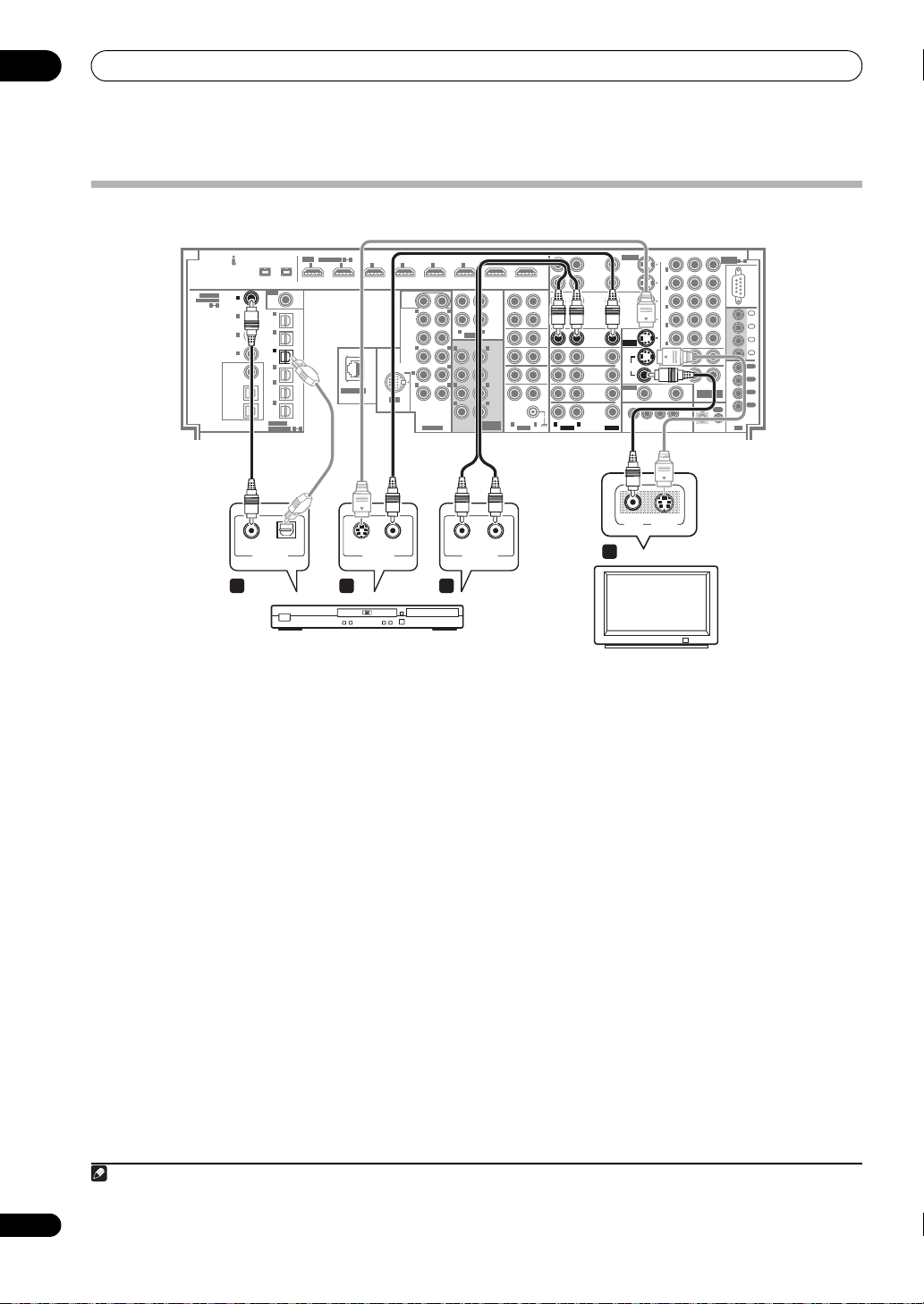
03
Connecting your equipment
Connecting your TV and DVD player
SC-LX90
61
HDMI
(AUDIO)
COAXIAL
1
1
IN
IN
ASSIGNABLE
(
)
(
)
DVD/LD
DVD/LD
1 4
2
IN
(BD)
3
IN
(CD)
4
IN
(DVR/
(DVR/
(SACD)
VCR 1)
VCR 1)
(DVR/
ZONE2
OUT
VCR 2)
(VIDEO/
GAME
ZONE3
/SOURCE
OUT
(CD-R/
SOURCE
OUT
COAXIAL AUDIORL
DIGITAL OUT VIDEO OUT
ASSIGNABLE
IN1IN2IN3IN4IN5IN
S400S400
RF IN
2
(
)
For LD
1
IN
(TV)
2
IN
(SAT)
3
3
IN
IN
4
IN
5
IN
IN
TAPE/
MD)
OPTICAL
ASSIGNABLE
1)
6
LAN (10/100)
1 6
S-VIDEOOPTICAL
12
SUB
WOOFER
L
R
FRONT
12
CENTER
LR
SURROUND
(
)
Single
SURROUND
L
BACK
R
IN
R
iPod
L
EXTRA
PRE OUT
3 2 4
DVD player
The diagram shows a basic setup of this amplifier
together with a TV and DVD player, with S-Video or
composite video connections. Different TVs and DVD
players may offer alternative connections. See also Using
the component video jacks on page 24 if your TV and/or
DVD player has component video inputs/outputs. If your
DVD player offers multichannel analog audio outputs,
see Connecting the multichannel analog inputs on
page 60.
1 Connect the
MONITOR OUT
video jack to a video
input on your TV.
Use a standard RCA/phono jack video cable to connect to
the composite video jack, or for higher quality video, use
an S-Video cable to connect to the S-Video jack.
2 Connect a composite or S-Video output on your
DVD player to the
DVD/LD VIDEO
or
DVD/LD S-VIDEO
input.
Connect using a standard video cable or an S-Video
cable.
YP
ZONE3
OUT
IN
(DVD/LD)
IN
(BD)
IN
(VIDEO/
GAME
1)
IN
(DVR/VCR 1)
IN
(DVR/VCR 2)
ZONE2
OUT
IN
BPR
ASSIGN-
5
1
1
2
3
4
5
ABLE
RS232C
IN
1
IN
2
IN
3
IN
4
OUT
1
OUT
2
OUT
COMPONENT
VIDEO
3
OUT
CONTROL
)
4
IN
OUT
IR
R
SUB W.
6
R
AUDIO
ANALOG OUT
OUT1
(HDMI CTRL)
L
MULTI CH
S-VIDEO
REC SEL
OUT2
ZONE2
OUT
ZONE3
OUT
L
FRONT
CENTER
LR
SURROUND
LR
SURROUND
BACK
AUDIO
IN
REC SEL
OUT
OUT
DVR/
VCR 1
IN
REC
SEL
OUT
CD-R/
TAPE/
MD
IN
CD
IN
SACD
IN
TUNER
IN
IN
PHONO
LR
R
IN
REC SEL
REC SEL
OUT
OUT
DVR/
VCR 2
IN
IN
IN
IN
(DVD/LD)
(DVD/LD)
DVD/LD
DVD/LD
IN
IN
ASSIGN-
ASSIGNABLE
ABLE
BD
IN
MONITOR
MONITOR
OUT
OUT
TV
IN
VIDEO
SAT
ZONE2
IN
OUT
12 V TRIGGER
VIDEO/
GAME 1
IN
VIDEOAUDIO
VIDEOAUDIO
1 2 34
(
DC OUT 12V TOTAL 250 mA MAX
LR
L
VIDEOINS-VIDEO
1
TV
4 Connect the stereo audio outputs on your DVD
player to the
DVD/LD AUDIO
inputs.
Connect using a stereo RCA/phono jack cable.
• If your DVD player has multichannel analog outputs,
you can connect these instead. See also Connecting
the multichannel analog inputs on page 60.
5 If the source component is an LD player with a
RF
digital audio output, connect this to the
on this amplifier.
To ensure compatibility with all laserdiscs, connect both
the PCM and 2 RF outputs from your LD player.
• Use a coaxial cable designed for digital audio for the
2 RF connection.
• You may need to assign the RF IN digital input when
setting up the amplifier (see also The Input Setup
menu on page 94).
RF IN
2
input
20
En
3 Connect a coaxial-type1 digital audio output on
your DVD player to the
COAXIAL IN 1 (DVD/LD
) input.
Use a coaxial cable designed for digital audio.
Note
1 If your DVD player only has an optical digital output, you can connect it to one of the optical inputs on this amplifier using an optical cable. When you set
up the amplifier you’ll need to tell the amplifier which input you connected the player to (see The Input Setup menu on page 94).
Page 21
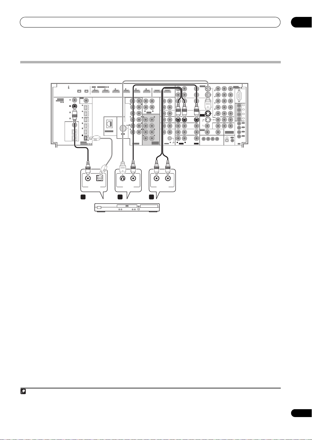
Connecting your equipment
Connecting your Blu-ray disc player
03
SC-LX90
61
HDMI
ASSIGNABLE
IN1IN2IN3IN4IN5IN
S400S400
RF IN
2
(
)
For LD
1
IN
(TV)
2
IN
(SAT)
3
IN
4
IN
5
IN
1)
6
6
IN
IN
(CD-R/
(CD-R/
TAPE/
TAPE/
MD)
MD)
OPTICAL
1 6
ASSIGNABLE
COAXIAL AUDIORL
DIGITAL OUT VIDEO OUT
LAN (10/100)
IN
iPod
S-VIDEOOPTICAL
SUB
WOOFER
CENTER
12
L
R
FRONT
12
LR
SURROUND
(
)
Single
SURROUND
L
BACK
R
R
L
EXTRA
PRE OUT
COAXIAL
ASSIGNABLE
(AUDIO)
1
IN
(
)
DVD/LD
1 4
2
2
IN
IN
(BD)
(BD)
3
IN
(CD)
4
IN
(DVR/
(SACD)
VCR 1)
(DVR/
ZONE2
OUT
VCR 2)
(VIDEO/
GAME
ZONE3
/SOURCE
OUT
SOURCE
OUT
3 2 4
Blu-ray disc player
The diagram shows a basic setup of this amplifier
together with a Blu-ray disc player, with S-Video or
composite video connections. See also Using the
component video jacks on page 24 if your Blu-ray disc
player has component video inputs/outputs. If your Bluray disc player offers multi-channel analog audio
outputs, see Connecting the multichannel analog inputs
on page 60.
1 Connect a composite video output on your Blu-ray
disc player to the
BD VIDEO
input.
Connect using a standard video cable or an S-Video1
cable.
YP
ZONE3
OUT
IN
(DVD/LD)
IN
(BD)
IN
(VIDEO/
GAME
1)
IN
(DVR/VCR 1)
IN
(DVR/VCR 2)
ZONE2
OUT
BPR
ASSIGN-
5
1
1
2
3
4
5
ABLE
RS232C
IN
1
IN
2
IN
3
IN
4
OUT
1
OUT
2
OUT
COMPONENT
VIDEO
3
OUT
CONTROL
)
4
IN
OUT
IR
OUT1
6
(HDMI CTRL)
OUT2
REC
SEL
OUT
ZONE2
OUT
CD-R/
TAPE/
MD
ZONE3
IN
OUT
L
R
AUDIO
R
SUB W.
MULTI CH
CD
L
LR
LR
IN
IN
SACD
FRONT
IN
TUNER
CENTER
IN
SUR-
IN
ROUND
PHONO
SURROUND
BACK
LR
AUDIO
S-VIDEO
REC SEL
REC SEL
OUT
OUT
DVR/
VCR 1
IN
IN
REC SEL
REC SEL
OUT
OUT
DVR/
VCR 2
IN
IN
IN
IN
(DVD/LD)
(DVD/LD)
DVD/LD
IN
ASSIGN-
ASSIGNABLE
ABLE
BD
BD
IN
IN
MONITOR
OUT
TV
IN
VIDEO
SAT
ZONE2
IN
OUT
12 V TRIGGER
VIDEO/
GAME 1
IN
VIDEOAUDIO
VIDEOAUDIO
1 2 34
(
DC OUT 12V TOTAL 250 mA MAX
LR
LR
ANALOG OUT
2 Connect an coaxial-type2 digital audio output on
your Blu-ray disc player to the
COAXIAL IN 2 (BD)
input.
Use a coaxial cable designed for digital audio.
3 Connect the stereo audio outputs on your Blu-ray
disc player to the
BD AUDIO
inputs.
Connect using a stereo RCA/phono jack cable.
• If your Blu-ray disc player has multi-channel analog
outputs, you can connect these instead. See also
Connecting the multichannel analog inputs on
page 60.
Note
1See The Input Setup menu on page 94 to assign the S-VIDEO input to the BD input function if you make this connection.
2 If your Blu-ray disc player only has an optical digital output, you can connect it to one of the optical inputs on this amplifier using an optical cable. When
you set up the amplifier, you’ll need to tell the amplifier which input you connected the player to (see The System Setup menu on page 40).
21
En
Page 22
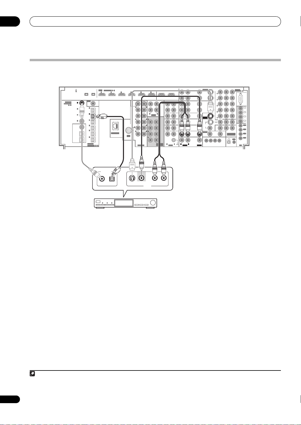
03
Connecting your equipment
Connecting a satellite/cable receiver or other set-top box
Satellite and cable receivers, and terrestrial digital TV tuners are all examples of so-called ‘set-top boxes’.
SC-LX90
COAXIAL
ASSIGNABLE
1 4
61
HDMI
(AUDIO)
1
1
IN
IN
(
)
(
)
DVD/LD
DVD/LD
2
IN
(BD)
3
IN
(CD)
4
IN
(DVR/
(SACD)
VCR 1)
(DVR/
ZONE2
OUT
VCR 2)
(VIDEO/
GAME
ZONE3
/SOURCE
OUT
(CD-R/
SOURCE
OUT
ASSIGNABLE
IN1IN2IN3IN4IN5IN
S400S400
RF IN
2
(
)
For LD
1
IN
(TV)
2
2
IN
IN
(SAT)
(SAT)
3
IN
4
IN
5
IN
IN
TAPE/
MD)
OPTICAL
ASSIGNABLE
1)
6
LAN (10/100)
1 6
OUT1
6
(HDMI CTRL)
OUT2
12
SUB
WOOFER
L
R
FRONT
12
L
R
CENTER
SURROUND
SURROUND
BACK
IN
iPod
EXTRA
AUDIO
LR
L
R
(
)
Single
SUB W.
L
R
R
PRE OUT
LR
L
LR
MULTI CH
REC
SEL
OUT
ZONE2
OUT
CD-R/
TAPE/
MD
ZONE3
IN
OUT
CD
IN
SACD
FRONT
CENTER
SURROUND
SURROUND
BACK
IN
IN
TUNER
IN
IN
PHONO
LR
AUDIO
S-VIDEO
REC SEL
REC SEL
OUT
OUT
DVR/
VCR 1
IN
REC SEL
OUT
DVR/
VCR 2
IN
DVD/LD
IN
BD
IN
TV
IN
SAT
SAT
IN
IN
VIDEO/
GAME 1
IN
LR
LR
VIDEOAUDIO
VIDEOAUDIO
IN
REC SEL
OUT
IN
IN
IN
(DVD/LD)
(DVD/LD)
ASSIGN-
ASSIGNABLE
ABLE
MONITOR
OUT
VIDEO
ZONE2
OUT
12 V TRIGGER
1 2 34
(
DC OUT 12V TOTAL 250 mA MAX
ZONE3
OUT
IN
(DVD/LD)
IN
(BD)
IN
(VIDEO/
GAME
1)
IN
(DVR/VCR 1)
IN
(DVR/VCR 2)
ZONE2
OUT
DIGITAL OUT
VIDEOS-VIDEO AUDIORL
AV OUT
YP
BPR
ASSIGN-
5
1
1
2
3
4
5
ABLE
RS232C
IN
1
IN
2
IN
3
IN
4
OUT
1
OUT
2
OUT
COMPONENT
VIDEO
3
OUT
CONTROL
)
4
IN
OUT
IR
22
En
STB
1 Connect the audio/video outputs on the set-top
box to the
SAT AUDIO
and
VIDEO
inputs.
Connect using a stereo RCA/phono jack cable and a
1
video or S-Video
cable.
2 Connect an optical-type2 digital audio output from
your set-top box to the
OPTICAL IN 2 (SAT)
input.
3
Use an optical cable for the connection.
Note
1 See The Input Setup menu on page 94 to assign the S-VIDEO input to the SAT input function if you make this connection.
2 If your set-top box only has a coaxial digital output, you can connect it to one of the coaxial inputs on this amplifier using a coaxial digital audio cable.
When you set up the amplifier you’ll need to tell the amplifier which input you connected the set-top box to (see The Input Setup menu on page 94).
3 If your satellite/cable receiver doesn’t have a digital audio output, you can skip this step.
Page 23
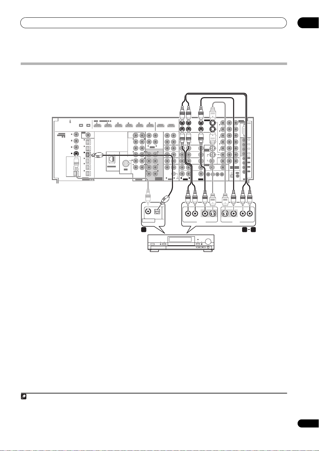
Connecting your equipment
Connecting a DVD/HDD recorder, VCR and other video sources
This amplifier has two sets of audio/video inputs and outputs suitable for connecting analog or digital video devices,
including DVD/HDD recorders and VCRs.
03
SC-LX90
61
HDMI
ASSIGNABLE
IN1IN2IN3IN4IN5IN
S400S400
RF IN
2
(
)
For LD
1
IN
(TV)
2
IN
(SAT)
3
3
IN
IN
4
IN
5
IN
IN
(CD-R/
TAPE/
MD)
OPTICAL
ASSIGNABLE
1)
6
LAN (10/100)
1 6
SUB
WOOFER
R
FRONT
CENTER
SURROUND
(
)
Single
SURROUND
BACK
R
IN
R
iPod
EXTRA
PRE OUT
COAXIAL
ASSIGNABLE
(AUDIO)
1
IN
(
)
DVD/LD
1 4
2
IN
(BD)
3
IN
(CD)
4
4
IN
IN
(DVR/
(DVR/
(SACD)
(SACD)
VCR 1)
VCR 1)
(DVR/
ZONE2
OUT
VCR 2)
(VIDEO/
GAME
ZONE3
/SOURCE
OUT
SOURCE
OUT
DIGITAL OUT
1 Connect the audio/video outputs of the video
player/recorder to the
DVR/VCR 1 AUDIO
and
VIDEO
inputs.
Use a stereo RCA/phono jack audio cable for the audio
connection and a video or S-Video cable for the video
connection.
• For a second recorder, use the DVR/VCR 2 IN inputs.
2 If the device can record, connect the
AUDIO
and
VIDEO
outputs to the recorder’s audio/
DVR/VCR 1
video inputs.
Use a stereo RCA/phono jack audio cable for the audio
connection and a video or S-Video cable for the video
connection.
• For a second recorder, use the DVR/VCR 2 OUT
outputs.
YP
ZONE3
OUT
IN
(DVD/LD)
IN
(BD)
IN
(VIDEO/
GAME
1)
IN
(DVR/VCR 1)
IN
(DVR/VCR 2)
ZONE2
OUT
BPR
ASSIGN-
5
1
1
2
3
4
5
ABLE
RS232C
IN
1
IN
2
IN
3
IN
4
OUT
1
OUT
2
OUT
COMPONENT
VIDEO
3
OUT
CONTROL
)
4
IN
OUT
IR
VIDEOS-VIDEO
AV IN
S-VIDEO
OUT1
6
(HDMI CTRL) OUT2
12
L
12
L
R
AUDIO
LR
R
SUB W.
L
L
MULTI CH
REC
SEL
OUT
ZONE2
OUT
CD-R/
TAPE/
MD
ZONE3
IN
OUT
CD
L
LR
LR
IN
IN
SACD
FRONT
IN
TUNER
CENTER
IN
SUR-
IN
ROUND
PHONO
SURROUND
BACK
LR
AUDIO
OPTICALCOAXIAL
S-VIDEO
REC SEL
REC SEL
REC SEL
REC SEL
OUT
OUT
OUT
OUT
DVR/
DVR/
VCR 1
VCR 1
IN
IN
IN
IN
REC SEL
REC SEL
OUT
OUT
DVR/
VCR 2
IN
IN
IN
(DVD/LD)
DVD/LD
IN
ASSIGNABLE
BD
IN
MONITOR
OUT
TV
IN
VIDEO
SAT
ZONE2
IN
OUT
12 V TRIGGER
VIDEO/
GAME 1
IN
LR
LR
1 2 34
(
DC OUT 12V TOTAL 250 mA MAX
VIDEOAUDIO
VIDEOAUDIO
VIDEOAUDIORL
S-VIDEO AUDIORL
AV OUT
1 23
DVR, VCR, etc.
3 If the device can output digital audio, connect an
optical-type
the
OPTICAL IN 3 (DVR/VCR 1
Use an optical cable for the connection.
1
digital audio output from the recorder to
) input.
2
• For a second recorder, use the OPTICAL IN 4 (DVR/
VCR 2) input.
Note
1 • In order to record, you must connect the analog audio cables (the digital connection is for playback only).
• If your video component doesn’t have a digital audio output, you can skip this step.
2 If your recorder only has a coaxial digital output, you can connect it to one of the coaxial inputs on this amplifier using a coaxial digital audio cable. When
you set up the amplifier you’ll need to tell the amplifier which input you connected the recorder to (see also The Input Setup menu on page 94).
23
En
Page 24
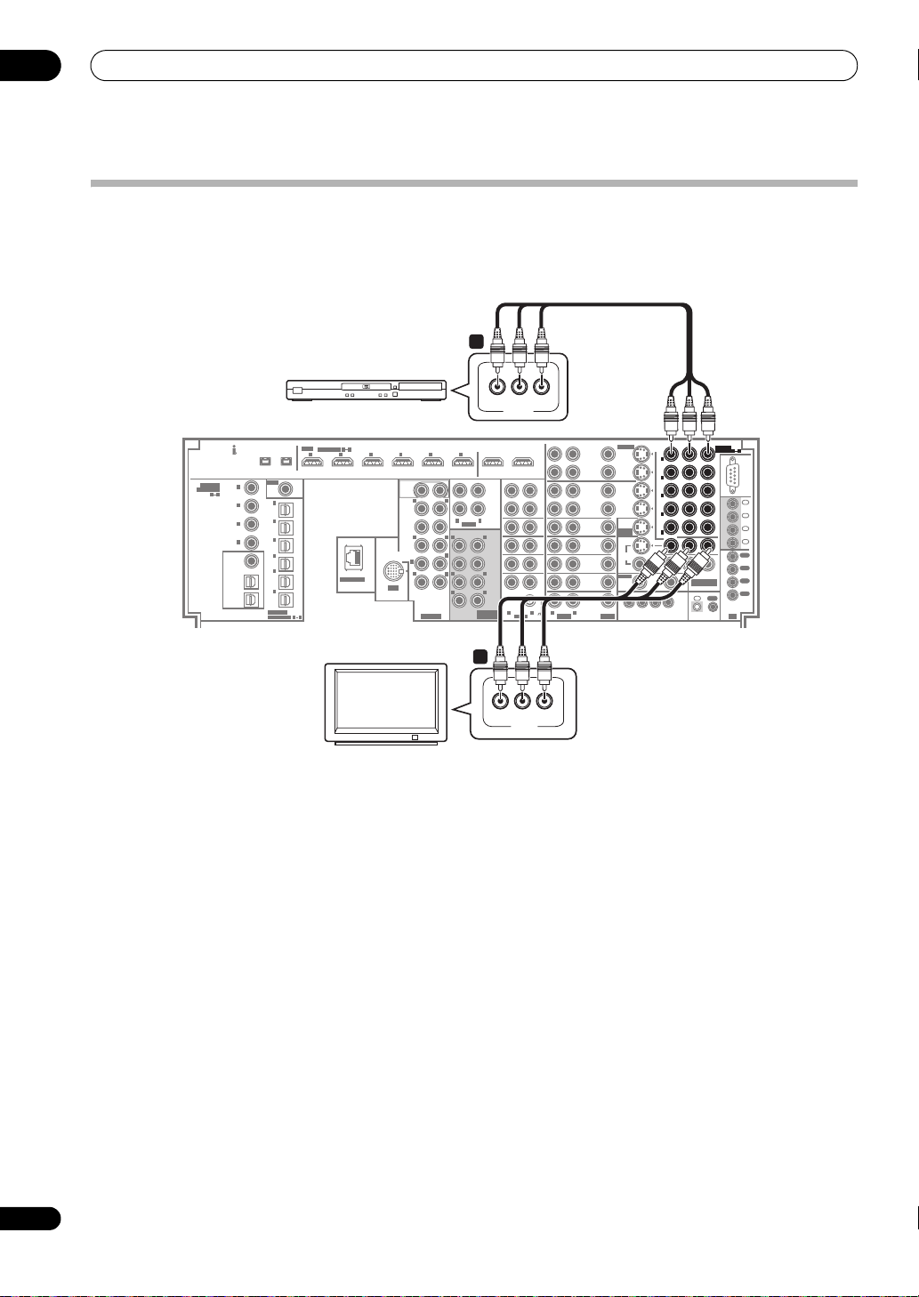
03
Connecting your equipment
Using the component video jacks
Component video should give superior picture quality when compared to composite or S-Video. You can also take
advantage of progressive scan video (if your source and TV are both compatible), which delivers a very stable, flickerfree picture. See the manuals that came with your TV and source component to check whether they are compatible
with progressive-scan video.
1
YPBP
R
COMPONENT
VIDEO
YP
BPR
YPBP
1
1
IN
IN
(DVD/LD)
(DVD/LD)
2
2
IN
IN
(BD)
(BD)
3
3
IN
IN
(VIDEO/
(VIDEO/
GAME
GAME
1)
1)
4
4
IN
IN
(DVR/VCR 1)
(DVR/VCR 1)
IN
5
5
IN
IN
(DVR/VCR 2)
(DVR/VCR 2)
ZONE2
OUT
ZONE3
OUT
12 V TRIGGER
1 2 34
(
DC OUT 12V TOTAL 250 mA MAX
R
ASSIGN-
ASSIGN-
1
5
1 5
ABLE
ABLE
RS232C
IN
1
IN
2
IN
3
IN
4
OUT
1
OUT
2
OUT
COMPONENT
VIDEO
3
OUT
CONTROL
4
IN
OUT
)
IR
OUT1
6
(HDMI CTRL) OUT2
REC
SEL
OUT
ZONE2
OUT
CD-R/
TAPE/
MD
ZONE3
IN
OUT
L
R
AUDIO
L
LR
LR
MULTI CH
CD
IN
SACD
FRONT
IN
TUNER
CENTER
IN
SUR-
IN
ROUND
PHONO
SURROUND
BACK
LR
AUDIO
IN
S-VIDEO
REC SEL
REC SEL
OUT
OUT
DVR/
VCR 1
IN
IN
REC SEL
REC SEL
OUT
OUT
DVR/
VCR 2
IN
IN
(DVD/LD)
DVD/LD
IN
ASSIGNABLE
BD
IN
MONITOR
OUT
TV
IN
VIDEO
SAT
ZONE2
IN
OUT
VIDEO/
GAME 1
IN
LR
VIDEOAUDIO
SC-LX90
COAXIAL
ASSIGNABLE
1 4
DVD player
61
HDMI
(AUDIO)
1
IN
(
)
DVD/LD
2
IN
(BD)
3
IN
(CD)
4
IN
(SACD)
ZONE2
OUT
(VIDEO/
ZONE3
/SOURCE
OUT
SOURCE
OUT
ASSIGNABLE
IN1IN2IN3IN4IN5IN
S400S400
RF IN
2
(
)
For LD
1
IN
(TV)
2
IN
(SAT)
3
IN
(DVR/
VCR 1)
4
IN
(DVR/
VCR 2)
5
IN
GAME
IN
(CD-R/
TAPE/
1)
6
MD)
OPTICAL
ASSIGNABLE
LAN (10/100)
1 6
12
SUB
WOOFER
L
R
FRONT
12
CENTER
LR
R
SURROUND
(
)
Single
SURROUND
SUB W.
L
BACK
R
IN
R
iPod
L
EXTRA
PRE OUT
TV
1 Connect the component video outputs of your
source to a set of
ASSIGNABLE COMPONENT VIDEO
inputs.
Connect using a three-way component video cable.
• Since they are assignable, it doesn’t matter which
component video inputs you use for which source.
After connecting everything, you’ll need to assign the
component video inputs—see The Input Setup menu
on page 94.
2 Connect the
COMPONENT VIDEO OUT
jacks to the
component video inputs on your TV or monitor.
Use a three-way component video cable.
2
YPBP
R
COMPONENT
VIDEO
24
En
Page 25
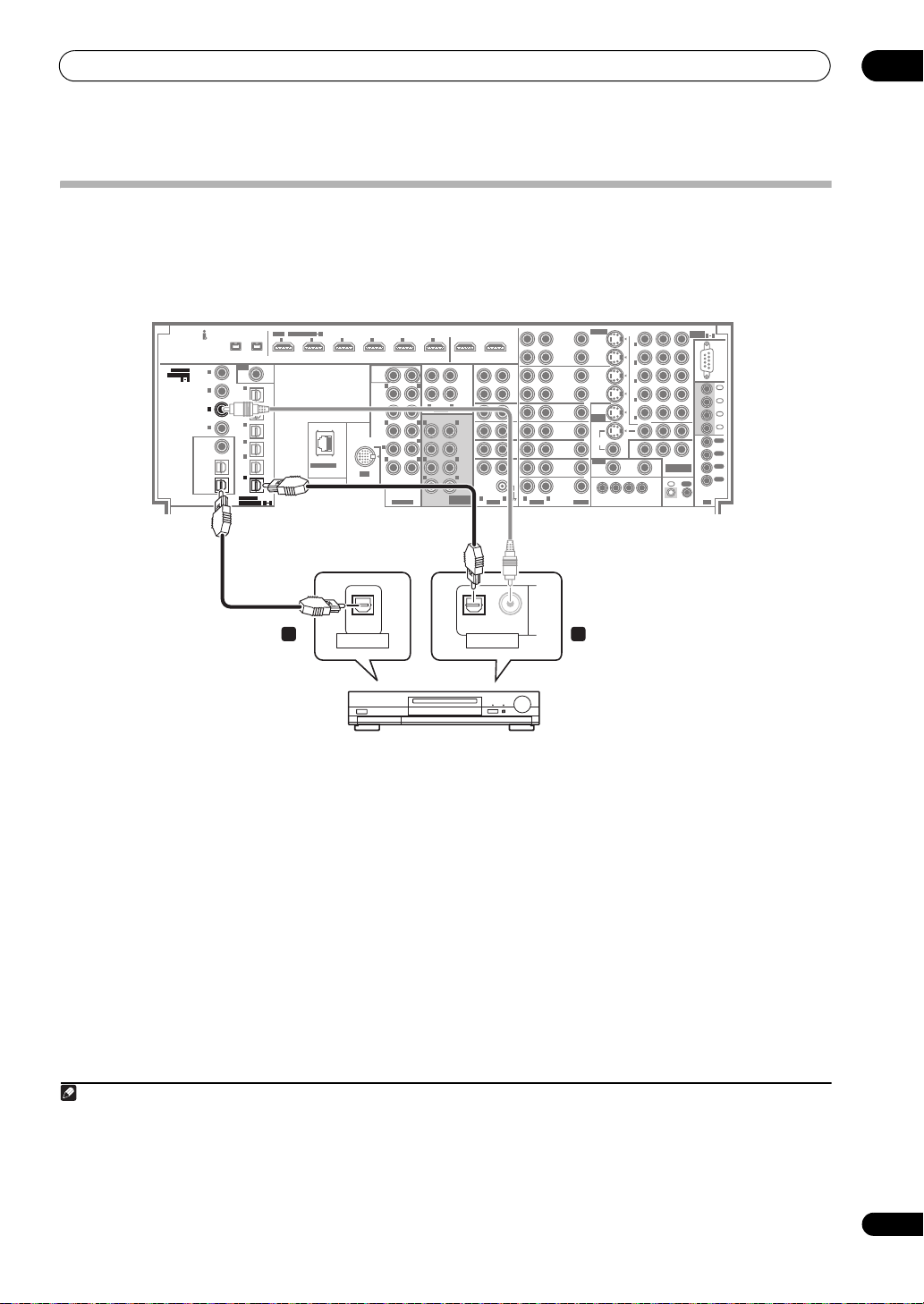
Connecting your equipment
Connecting digital audio sources
This amplifier has both digital inputs and outputs, allowing you to connect digital audio components for playback and
for making digital recordings.
Most digital components also have analog connections. See Connecting analog audio sources on page 26 if you want
to connect these too.
SC-LX90
COAXIAL
COAXIAL
ASSIGNABLE
ASSIGNABLE
1 4
1 4
61
HDMI
(AUDIO)
1
IN
(
)
DVD/LD
2
IN
(BD)
3
3
IN
IN
(CD)
(CD)
4
IN
(DVR/
(SACD)
VCR 1)
ZONE2
OUT
(VIDEO/
ZONE3
/SOURCE
OUT
SOURCE
SOURCE
OUT
OUT
ASSIGNABLE
IN1IN2IN3IN4IN5IN
S400S400
RF IN
2
(
)
For LD
1
IN
(TV)
2
IN
(SAT)
3
IN
4
IN
(DVR/
VCR 2)
5
IN
GAME
IN
IN
(CD-R/
(CD-R/
TAPE/
TAPE/
OPTICAL
OPTICAL
ASSIGNABLE
ASSIGNABLE
1)
6
6
MD)
MD)
LAN (10/100)
1 6
1 6
OUT1
6
(HDMI CTRL) OUT2
12
SUB
WOOFER
L
R
FRONT
12
L
R
CENTER
SURROUND
SURROUND
BACK
IN
iPod
EXTRA
AUDIO
LR
R
(
)
Single
SUB W.
L
R
R
L
PRE OUT
MULTI CH
REC
SEL
OUT
ZONE2
OUT
CD-R/
TAPE/
MD
ZONE3
IN
OUT
CD
L
LR
LR
IN
IN
SACD
FRONT
IN
TUNER
CENTER
IN
SUR-
IN
ROUND
PHONO
SURROUND
BACK
LR
AUDIO
S-VIDEO
REC SEL
REC SEL
OUT
OUT
DVR/
VCR 1
IN
REC SEL
OUT
DVR/
VCR 2
IN
DVD/LD
IN
BD
IN
TV
IN
SAT
IN
VIDEO/
GAME 1
IN
LR
VIDEOAUDIO
IN
REC SEL
OUT
IN
IN
(DVD/LD)
ASSIGNABLE
MONITOR
OUT
VIDEO
ZONE2
OUT
12 V TRIGGER
1 2 34
(
DC OUT 12V TOTAL 250 mA MAX
ZONE3
OUT
IN
(DVD/LD)
IN
(BD)
IN
(VIDEO/
GAME
1)
IN
(DVR/VCR 1)
IN
(DVR/VCR 2)
ZONE2
OUT
YP
BPR
ASSIGN-
5
1
1
2
3
4
5
ABLE
RS232C
IN
1
IN
2
IN
3
IN
4
OUT
1
OUT
2
OUT
COMPONENT
VIDEO
3
OUT
CONTROL
)
4
IN
OUT
IR
03
OPTICAL
DIGITAL IN
OPTICAL COAXIAL
DIGITAL OUT
12
CD-R, MD, DAT, etc.
1 Connect an optical-type1 digital audio output on
your digital component to the
TAPE/MD)
input.
OPTICAL IN 6 (CD-R/
Use an optical cable for the connection.
2 For recording equipment, connect one of the
optical-type
DIGITAL
outputs to a digital input on the
recorder.
Use an optical cable to connect to the SOURCE OUT or
ZONE3/SOURCE OUT.
2
About the WMA9 Pro decoder
This unit has an on-board Windows Media™ Audio 9
Professional
playback WMA9 Pro-encoded audio using a coaxial or
optical digital connection when connected to a WMA9
Pro-compatible player. However, the connected PC, DVD
player, set-top box, etc. must be able to output WMA9 Pro
format audio signals through a coaxial or optical digital
output.
3
(WMA9 Pro) decoder, so it is possible to
Note
1 • If your digital component only has a coaxial digital output, you can connect it to one of the coaxial inputs on this amplifier using a coaxial cable. When
you set up the amplifier you’ll need to tell the amplifier which input you connected the component to (see also The Input Setup menu on page 94).
• The digital outputs from other components can be connected to any spare digital audio inputs on this amplifier. You can assign them when setting up
the amplifier (see also The Input Setup menu on page 94).
2 • You must switch ZONE 3 ON in Using the MULTI-ZONE controls on page 66 to hear audio from the DIGITAL OUT1.
• In order to record some digital sources, you must make analog connections as explained in Connecting analog audio sources on page 26.
3• Windows Media and the Windows logo are trademarks or registered trademarks of Microsoft Corporation in the United States and/or other countries.
• With WMA9 Pro, sound problems may occur depending on your computer system. Note that WMA9 Pro 96 kHz sources will be downsampled to 48 kHz.
25
En
Page 26
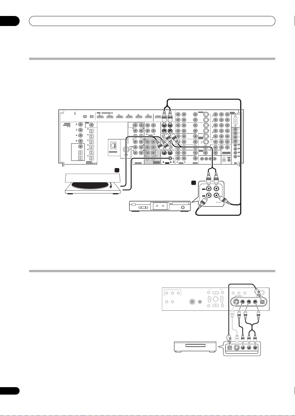
03
Connecting your equipment
Connecting analog audio sources
This amplifier features five stereo audio-only inputs. One of these inputs have corresponding outputs for use with audio
recorders.
One of the audio inputs (PHONO) is a dedicated turntable input which should not be used for any other type of
component. This input also has a grounding terminal that most turntables require.
SC-LX90
61
HDMI
ASSIGNABLE
IN1IN2IN3IN4IN5IN
S400S400
RF IN
2
(
)
For LD
1
IN
(TV)
2
IN
(SAT)
3
IN
4
IN
(DVR/
VCR 2)
5
GAME
(CD-R/
IN
IN
TAPE/
OPTICAL
1)
6
MD)
ASSIGNABLE
LAN (10/100)
1 6
SUB
WOOFER
R
FRONT
CENTER
SURROUND
(
SURROUND
BACK
R
IN
R
iPod
EXTRA
PRE OUT
COAXIAL
ASSIGNABLE
(AUDIO)
1
IN
(
)
DVD/LD
1 4
2
IN
(BD)
3
IN
(CD)
4
IN
(DVR/
(SACD)
VCR 1)
ZONE2
OUT
(VIDEO/
ZONE3
/SOURCE
OUT
SOURCE
OUT
2
Turntable
Tape deck, etc.
1 Connect the analog audio outputs of the source
component to one of the
AUDIO
inputs.
Connect using a stereo RCA/phono jack audio cable.
• If you’re connecting a tape deck, MD recorder, etc.,
connect the analog audio outputs (RECSEL OUT) to
the analog audio inputs on the recorder.
YP
ZONE3
OUT
R L
AUDIO IN/OUT
IN
(DVD/LD)
IN
(BD)
IN
(VIDEO/
GAME
1)
IN
(DVR/VCR 1)
IN
(DVR/VCR 2)
ZONE2
OUT
BPR
ASSIGN-
5
1
1
2
3
4
5
ABLE
RS232C
IN
1
IN
2
IN
3
IN
4
OUT
1
OUT
2
OUT
COMPONENT
VIDEO
3
OUT
CONTROL
)
4
IN
OUT
IR
OUT1
6
(HDMI CTRL)
OUT2
REC
12
L
12
L
R
AUDIO
LR
L
R
)
Single
SUB W.
L
LR
L
LR
MULTI CH
REC
SEL
SEL
OUT
OUT
ZONE2
OUT
CD-R/
CD-R/
TAPE/
TAPE/
MD
MD
ZONE3
IN
IN
OUT
CD
IN
SACD
FRONT
IN
TUNER
CENTER
IN
SUR-
IN
IN
ROUND
PHONO
PHONO
SURROUND
BACK
LR
LR
AUDIO
AUDIO
IN
2
Turntables only:
the
PHONO
S-VIDEO
REC SEL
REC SEL
OUT
OUT
DVR/
VCR 1
IN
IN
REC SEL
REC SEL
OUT
OUT
DVR/
VCR 2
IN
IN
IN
(DVD/LD)
DVD/LD
IN
ASSIGNABLE
BD
IN
MONITOR
OUT
TV
IN
VIDEO
SAT
ZONE2
IN
OUT
12 V TRIGGER
VIDEO/
GAME 1
IN
VIDEOAUDIO
1
1 2 34
(
DC OUT 12V TOTAL 250 mA MAX
OUT
PLAY
IN
REC
LR
Connect the stereo audio outputs to
inputs.
• If your turntable has a grounding wire, secure it to the
ground terminal on this amplifier.
• If your turntable has line-level outputs (i.e., it has a
built-in phono pre-amp), connect it to the CD inputs
instead.
26
En
Connecting a component to the front panel inputs
The front panel inputs comprise a composite video jack
(VIDEO), an S-Video jack (S-VIDEO), stereo analog audio
inputs (AUDIO L/R) and an optical digital audio input
(DIGITAL IN). You can use these connections for any kind
of audio/video component, but they are especially
convenient for portable equipment such as camcorders,
video games and portable audio/video equipment.
• Push down on the lower portion of the front panel
door to access the front video connections.
ZONE2 ZONE3
CTRL
MULTI-ZONE CONTROL
SPEAKERS AUTO SURROUND
/STREAM DIRECT
TV game, video camera,
etc.
• Select these inputs using INPUT SELECT (remote) or
the INPUT SELECTOR dial (front panel) to select
VIDEO/GAME 2.
PHONES
MCACC
SETUP MIC
PARAMETER
AUDIO VIDEO
ENTER
SETUP
RETURN
STATUS
DIGITAL OUT
LCD
VIEW DIMMER
VIDEO/GAME 2 INPUT
VIDEO/GAME 2 INPUT
VIDEO OUTPUT
USB
DIGITAL INS-VIDEO VIDEO L R
DIGITAL INS-VIDEO VIDEO L RAUDIO
AUDIO
Page 27
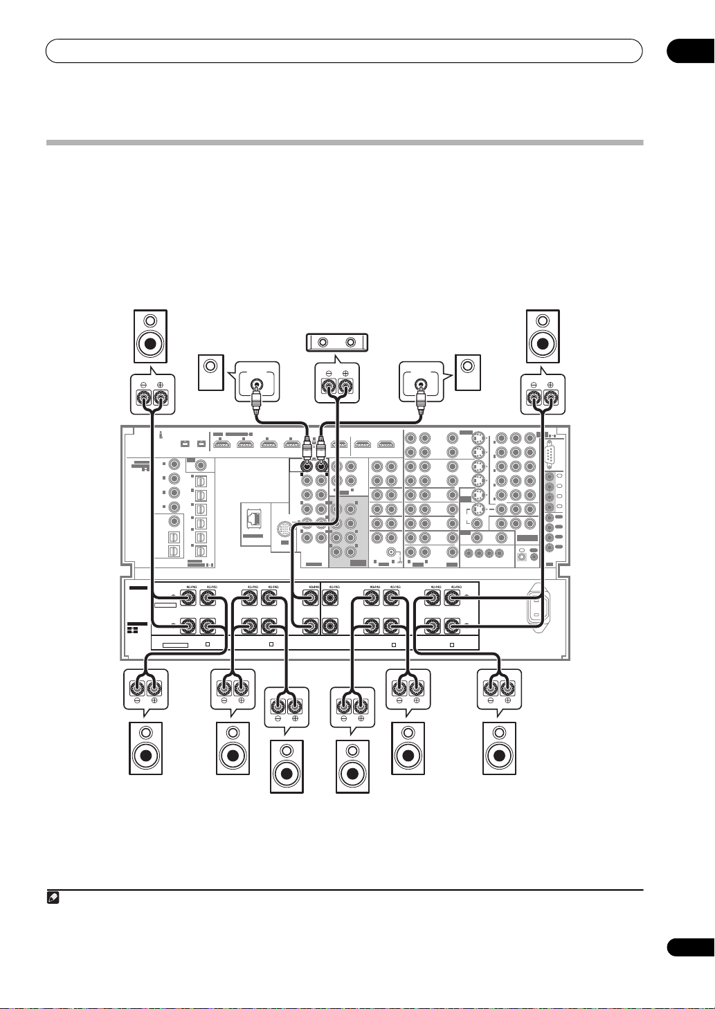
Connecting your equipment
Installing your speaker system
To take full advantage of the amplifier’s surround sound
capabilities connect front, center, surround A, surround
B and surround back speakers, as well as subwoofers.
Although this is ideal, other configurations with fewer
speakers—no subwoofer or no center speaker, or even no
surround speakers—will work. At the very least, front left
and right speakers only are necessary. Note that your
main surround speakers should always be connected as
a pair, but you can connect just one surround back
Front
right
Subwoofer 2
LINE LEVEL
INPUT
61
HDMI
ASSIGNABLE
IN1IN2IN3IN4IN5IN
S400S400
RF IN
2
(
)
For LD
1
IN
(TV)
2
IN
(SAT)
3
IN
(DVR/
VCR 1)
4
IN
(DVR/
VCR 2)
5
IN
GAME
1)
6
IN
(CD-R/
TAPE/
MD)
OPTICAL
ASSIGNABLE
R2
4Ω16ΩR26Ω16Ω
FRONT
FRONT
LAN (10/100)
1 6
R3
R3 R4 R5 L5
SUR-
SUR-
SUR-
SUR-
ROUND-B
ROUND-B
ROUND-A
ROUND-A
LOW HIGH
LOW HIGH
R
R
6Ω16ΩR46Ω16Ω
SURROUND
SURROUND
IN
SURROUND
SURROUND
R
R
iPod
BACK
BACK
COAXIAL
ASSIGNABLE
SPEAKERS
SPEAKERS
SELECTABLE
SELECTABLE
SELECTABLE
SELECTABLE
R1 R5
R1 R5
L1
L5
L1
L5
SEE
SEE
INSTRUCTION
INSTRUCTION
MANUAL
MANUAL
VOIR LE MODE
VOIR LE MODE
D'EMPLOI
D'EMPLOI
(AUDIO)
1
IN
(
)
DVD/LD
1 4
2
IN
(BD)
3
IN
(CD)
4
IN
(SACD)
ZONE2
OUT
(VIDEO/
ZONE3
/SOURCE
OUT
SOURCE
OUT
R1
R1
Normal
Normal
FRONT FRONTCENTER
FRONT FRONTCENTER
LOW HIGH
LOW HIGH
All ch Bi-Amp.
All ch Bi-Amp.
SUB
SUB
WOOFER
WOOFER
CENTER
FRONT
SURROUND
SURROUND
BACK
R
EXTRA
2
R
R
PRE OUT
R5
6Ω16ΩL56Ω16Ω
LOW HIGH
LOW HIGH
(
Single
CENTER
CENTER
1
Center
1
12
L
LR
12
LR
)
L
L
speaker if you like (it must be connected to the left
surround back terminal). The following connections
example is for 9.2-channel surround connections. Note
that many other speaker layouts and usage patterns are
also possible. For details see Selecting the speaker layout/
usage pattern on page 9.
You can use speakers with a nominal impedance
between 6 Ω and 16 Ω (or between 4 Ω and 16 Ω for the
R1/L1 terminals).
Front
left
Subwoofer 1
LINE LEVEL
INPUT
BPR
OUT1
6
(HDMI CTRL) OUT2
ZONE2
OUT
ZONE3
OUT
L
R
AUDIO
L
R
FRONT
SUB W.
CENTER
LR
SURROUND
LR
SURROUND
BACK
MULTI CH
IN
L4
L4 L3 L2 L1
6Ω16ΩL36Ω16Ω
SURROUND
SURROUND
BACK
BACK
(Single)
(Single)
HIGH LOW
HIGH LOW
SURROUND
SURROUND
S-VIDEO
REC SEL
REC SEL
OUT
OUT
DVR/
VCR 1
IN
REC
SEL
OUT
REC SEL
OUT
CD-R/
TAPE/
MD
IN
CD
IN
SACD
IN
TUNER
IN
IN
PHONO
LR
AUDIO
SUR-
SUR-
ROUND-B
ROUND-B
L
L
SUR-
SUR-
ROUND-A
ROUND-A
DVD/LD
LR
L2
6Ω16Ω
HIGH LOW
HIGH LOW
DVR/
VCR 2
IN
IN
BD
IN
TV
IN
SAT
IN
VIDEO/
GAME 1
IN
VIDEOAUDIO
L1
FRONT
FRONT
REC SEL
OUT
(DVD/LD)
ASSIGNABLE
MONITOR
OUT
VIDEO
ZONE2
OUT
4Ω16Ω
L
L
IN
IN
IN
ZONE2
OUT
ZONE3
OUT
12 V TRIGGER
1 2 34
(
DC OUT 12V TOTAL 250 mA MAX
IN
(DVD/LD)
IN
(BD)
IN
(VIDEO/
GAME
1)
IN
(DVR/VCR 1)
IN
(DVR/VCR 2)
YP
ASSIGN-
5
1
1
2
3
4
5
ABLE
RS232C
IN
1
IN
2
IN
3
IN
4
OUT
1
OUT
2
OUT
COMPONENT
VIDEO
3
OUT
CONTROL
)
4
IN
OUT
IR
AC IN
SC-LX90
03
Surround
right A
Surround
right B
Surround
back right
Surround
back left
Surround
left B
Note
1 • When using one subwoofer, connect it to the SUBWOOFER 1 terminal.
• When using only one surround back speaker, connect it to the L4 (Single) terminals.
• When only two surround speakers are connected, connect them to the L2 (SL A) and R2 (SR A) terminals.
Surround
left A
27
En
Page 28
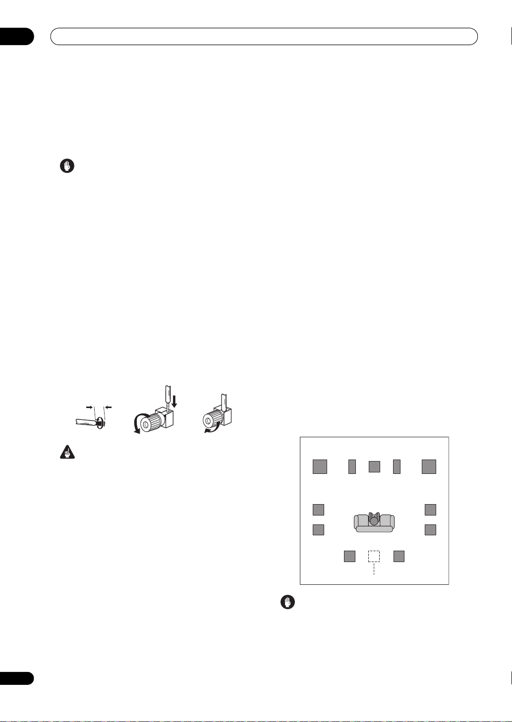
03
Connecting your equipment
Connecting the speakers
Each speaker connection on the amplifier comprises a
positive (+) and negative (–) terminal. Make sure to
match these up with the terminals on the speakers
themselves.
Caution
• These speaker terminals carry HAZARDOUS LIVE
voltage. To prevent the risk of electric shock when
connecting or disconnecting the speaker cables,
disconnect the power cord before touching any
uninsulated parts.
• Make sure that all the bare speaker wire is twisted
together and inserted fully into the speaker terminal.
If any of the bare speaker wire touches the back panel
it may cause the power to cut off as a safety measure.
Bare wire connections
Make sure that the speaker cable you’re going to use is
properly prepared with about 10 mm of insulator stripped
from each wire, and the exposed wire strands twisted
together (fig. A).
To connect a terminal, unscrew the terminal a few turns
until there is enough space to insert the exposed wire
(fig. B). Once the wire is in position, tighten the terminal
until the wire is firmly clamped (fig. C).
fig. A fig. B fig. C
10 mm
• When placing speakers near the TV, we recommend
using magnetically shielded speakers to prevent
possible interference, such as discoloration of the
picture when the TV is switched on. If you do not have
magnetically shielded speakers and notice
discoloration of the TV picture, move the speakers
farther away from the TV.
• If you’re using a center speaker, place the front
speakers at a wider angle. If not, place them at a
narrower angle.
• Place the center speaker above or below the TV so
that the sound of the center channel is localized at
the TV screen. Also, make sure the center speaker
does not cross the line formed by the leading edge of
the front left and right speakers.
• It is best to angle the speakers towards the listening
position. The angle depends on the size of the room.
Use less of an angle for bigger rooms.
• Surround and surround back speakers should be
positioned 60 cm to 90 cm higher than your ears and
titled slight downward. Make sure the speakers don’t
face each other. For DVD-Audio, the speakers should
be more directly behind the listener than for home
theater playback.
• Try not to place the surround speakers farther away
from the listening position than the front and center
speakers. Doing so can weaken the surround sound
effect.
• To achieve the best possible surround sound, install
your speakers as shown below. Be sure all speakers
are installed securely to prevent accidents and
improve sound quality.
28
En
Important
• Please refer to the manual that came with your
speakers for details on how to connect the other end
of the speaker cables to your speakers.
• If you are using a THX certified subwoofer use the
THX INPUT jack on the subwoofer (if your subwoofer
has one) or switch the filter position to THX on your
subwoofer.
Placing the speakers
Where you put your speakers in the room has a big effect
on the quality of the sound. The following guidelines
should help you to get the best sound from your system.
• The subwoofer can be placed on the floor. Ideally, the
other speakers should be at about ear-level when
you’re listening to them. Putting the speakers on the
floor (except the subwoofer), or mounting them very
high on a wall is not recommended.
• For the best stereo effect, place the front speakers
2 m to 3 m apart, at equal distance from the TV.
Front
left
Subwoofer
Surround
left A
Surround
left B
Surround back left
Listening position
Single surround back speaker
Center
Subwoofer
Surround back right
Front
right
Surround
right A
Surround
right B
Caution
• Make sure that all speakers are securely installed.
This not only improves sound quality, but also
reduces the risk of damage or injury resulting from
speakers being knocked over or falling in the event of
external shocks such as earthquakes.
Page 29
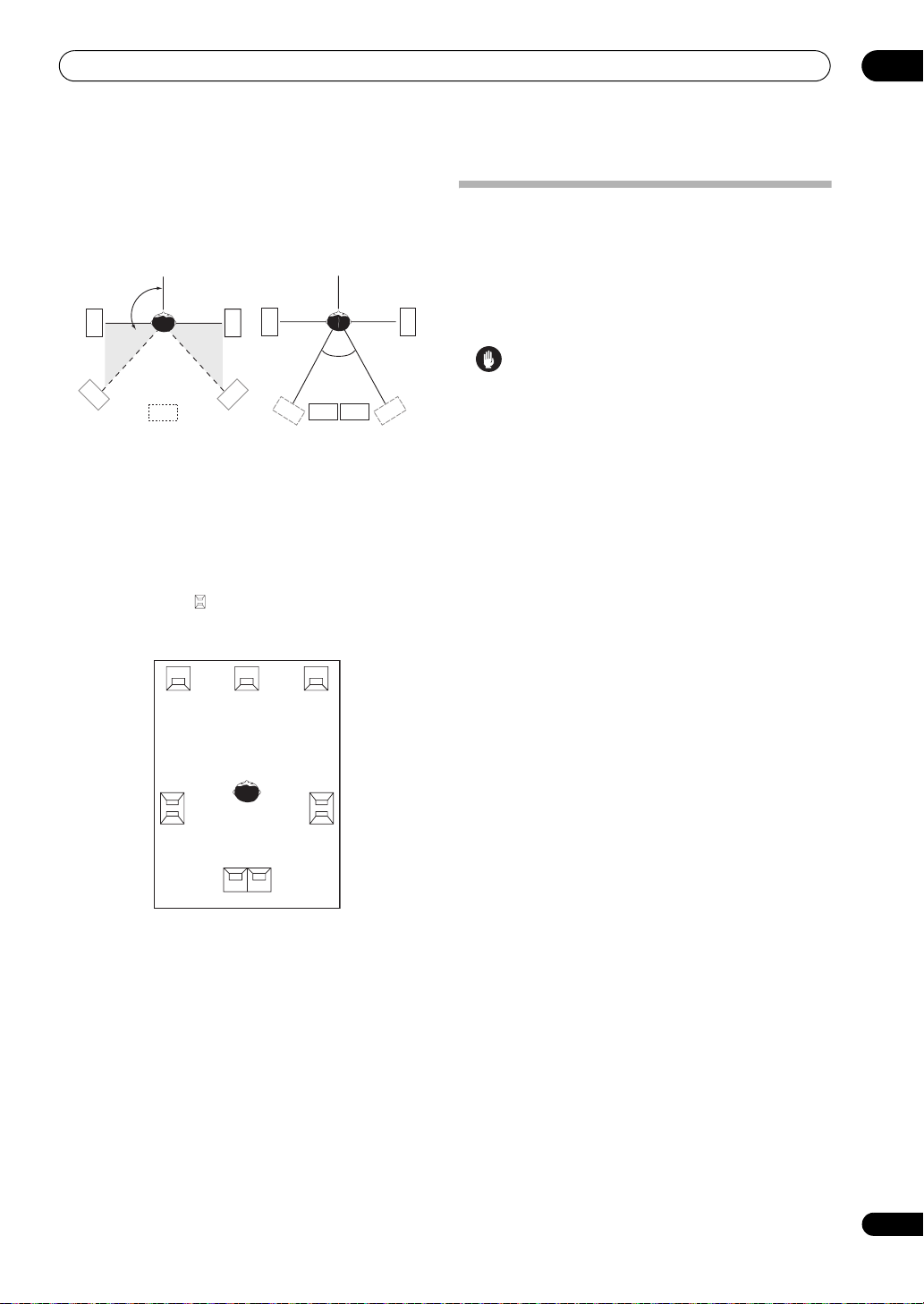
Connecting your equipment
The diagrams below show suggested surround and
surround back speaker orientation. The first diagram (fig.
A) shows orientation with one surround back speaker (or
none) connected. The second (fig. B) shows orientation
with two surround back speakers connected.
90° to 120°
LS
LS
RS
RS
Plugging in the amplifier
Only plug in after you have connected all your
components to this amplifier, including the speakers.
1 Plug the supplied power cord into the
on the back of the amplifier.
2 Plug the other end into a power outlet.
AC IN
socket
03
0° to 60°
LS
SB
fig. A
RS
fig. B
SBL
SBL
SBR
SBR
• If you have two surround back speakers THX
recommends placing them together and the same
distance from your listening position (see below).
THX speaker system setup
If you have a complete THX speaker system, follow the
diagram below to place your speakers. Note that the
surround speakers ( indicates bi-polar radiating
speakers) should output at an angle parallel to the
listener.
L
SL
Surround
C
R
SR
Surround
Caution
• Handle the power cord by the plug part. Do not pull
out the plug by tugging the cord, and never touch the
power cord when your hands are wet, as this could
cause a short circuit or electric shock. Do not place
the unit, a piece of furniture, or other object on the
power cord or pinch the cord in any other way. Never
make a knot in the cord or tie it with other cables. The
power cords should be routed so that they are not
likely to be stepped on. A damaged power cord can
cause a fire or give you an electric shock. Check the
power cord once in a while. If you find it damaged,
ask your nearest Pioneer authorized independent
service company for a replacement.
• The amplifier should be disconnected by removing
the mains plug from the wall socket when not in
regular use, e.g., when on vacation.
•Make sure the blue STANDBY/ON light has gone
out before unplugging.
SBL
Surround back
SBR
• If you have two surround back speakers THX
recommends placing them together and the same
distance from your listening position for the following
THX modes: THX Ultra2 CINEMA, THX Ultra2
MUSIC and THX Ultra2 GAMES.
See also THX Audio Setting on page 54 to make the
settings that will give you the best sound experience
when using the Home THX modes (page 35).
29
En
Page 30
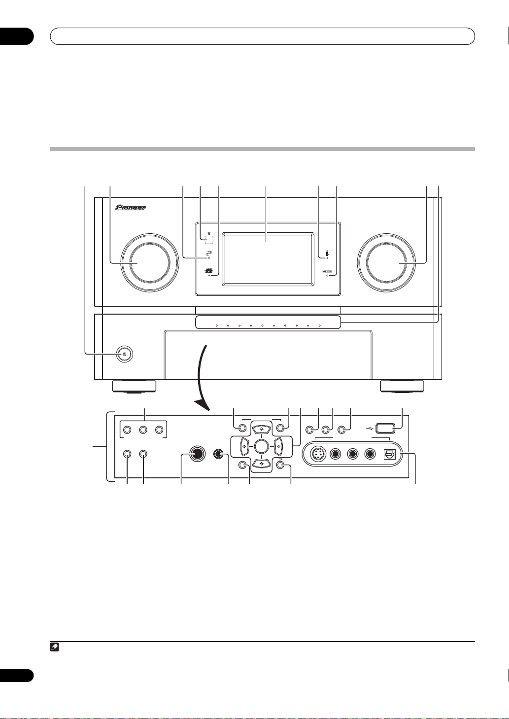
04
Controls and displays
Chapter 4:
Controls and displays
Front panel
1 2
INPUT
SELECTOR
STANDBY/ON
12
ZONE2 ZONE3
CTRL
MULTI-ZONE CONTROL
SPEAKERS AUTO SURROUND
/STREAM DIRECT
3 75 89106
4
ACTIVE MONITOR
13 14 15 16 18 1917
PARAMETER
AUDIO VIDEO
ENTER
MCACC
PHONES
SETUP MIC
SETUP
SC-LX90
MASTER
VOLUME
STATUS
R1R2R3R4R5
LCD
VIEW
DIMMER
VIDEO/GAME 2 INPUT
AUDIO
USB
DIGITAL INS-VIDEO VIDEO L R
L5L4L3L2L1
RETURN
30
En
201121 22 23 24 25 26
1
STANDBY/ON
Switches the amplifier between on and standby. Power
indicator lights when the amplifier is on.
2
INPUT SELECTOR
Use to select an input source.
3
PHASE CONTROL
Lights to indicate Phase Control or Full Band Phase
Control is selected (page 14).
4 Remote sensor
Receives the signals from the remote control (see
Operating range of remote control unit on page 31).
Note
1 The MCACC indicator does not light when the MCACC preset memory currently being selected has not been corrected with Acoustic Calibration EQ
Professional or when EQ is set to OFF in the AUDIO PARAMETER menu (see Setting the Audio options on page 99).
dial
indicator
5
ADVANCED MCACC
indicator
Lights when one of the MCACC presets (page 37) is
selected.
1
6 LCD display
7
i.LINK
indicator
Lights when an i.LINK-Audio-equipped component is
selected (page 58).
8
HDMI
indicator
Blinks when connecting an HDMI-equipped component;
lights when the component is connected (page 18).
Page 31

Controls and displays
9
MASTER VOLUME
10
ACTIVE MONITOR
The indicators of the speaker terminals compatible with
sound output are lit.
11 Front panel controls
To access the front panel controls, push gently on the
lower third portion of the panel with your finger.
INPUT
SELECTOR
STANDBY/ON
12
MULTI-ZONE CONTROL
If you’ve made MULTI-ZONE connections (see MULTIZONE listening on page 64) use these controls to control
the sub zone from the main zone (see Using the MULTIZONE controls on page 66).
13
AUDIO PARAMETER
Use to access the Audio options (page 99).
14
VIDEO PARAMETER
Use to access the Video options (page 101).
15
/// /ENTER
Use the arrow buttons when setting up your surround
sound system (see page 40).
16
STATUS
Information on the currently selected and set functions,
the input signal, etc., is displayed on the LCD (page 104).
17
LCD VIEW
The information shown on the LCD can be switched in
three steps (page 103).
18
DIMMER
Dims or brightens the LCD display (page 103).
19
USB
interface
Connect a USB audio device for playback (page 73).
20
SPEAKERS
Use to change the speaker system (page 61).
21
AUTO SURROUND/STREAM DIRECT
Press to select Auto Surround (page 34) or Stream Direct
(page 36) listening.
22
PHONES
jack
Use to connect headphones. When the headphones are
connected, there is no sound output from the speakers.
23
MCACC SETUP MIC
Use to connect the supplied microphone.
24
SETUP
Press to access the System Setup menu (page 40).
L1
L2
L3
ACTIVE MO
L4
N
L5
ITOR
R5
R4
R3
dial
indicator
S
C
-L
X
9
0
R2
R1
M
A
STE
V
O
R
LU
M
E
jack
25
RETURN
Press to confirm and exit the current menu screen.
26
VIDEO/GAME 2 INPUT
See Connecting a component to the front panel inputs on
page 26.
Operating range of remote control unit
The remote control may not work properly if:
• There are obstacles between the remote control and
the amplifier’s remote sensor.
• Direct sunlight or fluorescent light is shining onto the
remote sensor.
• The amplifier is located near a device that is emitting
infrared rays.
• The amplifier is operated simultaneously with
another infrared remote control unit.
INP
U
T
SE
L
E
C
T
30°
30°
7 m
OR
S
T
A
N
D
B
Y
/O
N
L1
L
2
L3
L4
SC-LX90
ACTI
V
E M
ONITOR
L
5
R5
R4
R
3
R2
R1
MASTER
VOLUME
04
31
En
Page 32

04
Controls and displays
Remote control
1
MAIN
AV AMPLIFIER
DVD
DVR1
HOME MEDIA
GALLERY
TUNER
ZONE2
DVR2
PHONO
2
3
4
5
CH
6
TV CONTROL
INPUT MUTE MUTE
AUDIO
PARAMETER
7
TOP MENU
8
SETUP
STATUS
9
THX
STEREO/
AUTO/
F.S.SURR
10
11
DIRECT
SIGNAL SEL SLEEP AUDIODIMMER
SR+
A.ATT GENRE
CLR
The remote has been conveniently color-coded according
to component control using the following system:
• White – amplifier control, TV Control
• Blue – Other controls
1 MULTI-ZONE operation selector switch
Switch to perform operations in the main zone, zone 2
and zone 3 (page 64).
2
AV AMPLIFIER
This switches between standby and on for this amplifier.
3
MULTI OPERATION
Use this button to perform multi operations (page 108).
4 Input source buttons
Press to select control of other components (see
Controlling the rest of your system on page 106).
SOURCE
3
MULTI
OPERATION
BD TV SAT
VIDEO1
VIDEO2
CD
TV AMP
MCACC
CD-R
SACD
iPo d HDMI
INPUT SELECT
SOURCE
VOL
PARAMETER
ENTER
CH LEVEL
STANDARD AD V SURR
SBch PHASE iPod CTRL
DISP
HDMI OUT
CH
ENTER
VOL
VIDEO
MENU
RETURN
12
13
14
15
16
5 Character display (LCD)
This display shows information when transmitting
control signals.
The following commands are shown when you’re setting
the remote to control other components (see Controlling
the rest of your system on page 106):
SETUP – Indicates the setup mode, from which you
choose the options below.
PRESET – See Selecting preset codes directly on
page 106.
LEARNING – See Programming signals from other
remote controls on page 106.
MULTI OP – See Multi Operation and System Off on
page 108.
SYS OFF – See Multi Operation and System Off on
page 108.
DIRECT F – See Direct function on page 108.
RENAME – See Renaming input source names on
page 108.
ERASE – See Erasing one of the remote control button
settings on page 107.
RESET – See Resetting the remote control presets on
page 107.
READ ID – See Confirming preset codes on page 108.
6
TV CONTROL
buttons
These buttons are dedicated to control the TV assigned to
the TV button. Thus if you only have one TV to hook up to
this system assign it to the TV input source button (see
page 106 for more on this).
TV – Use to turn on/off the power of the TV.
TV VOL +/– – Use to adjust the volume on your TV.
INPUT – Use to select the TV input signal.
TV CH +/– – Use to select channels.
MUTE – Use to mute the sound or cancel the mute
mode.
7 Tuner/component control buttons/
SETUP
These button controls can be accessed after you have
selected the corresponding input source button (DVD,
DVR 1, TV, etc.). Set the operation selector switch to
AMP to access the following controls:
AUDIO PARAMETER – Use to access the Audio
options (page 99).
VIDEO PARAMETER – Use to access the Video
options (page 101).
SETUP – Use to access the System Setup menu
(page 40).
RETURN – Press to confirm and exit the current
menu screen (also use to return to the previous menu
with DVDs or to select closed captioning with DTV).
32
En
Page 33

Controls and displays
THX
AUTO/
DIRECT
STANDARD
R
VIDEO
PARAMETER
MENU
OP MENU
RETURN
STATUS
CH LEVEL
ADV SURR
STEREO/
F.S.SURR
MUTE
SETUP
MUTE
ENTER
8
/// /ENTER
Use the arrow buttons when setting up your surround
sound system (see page 40) and the Audio or Video
options (page 99 or 101). Also used to control DVD
menus/options and for deck 1 of a double cassette deck
player.
9 Component control buttons
The main buttons (, , etc.) are used to control a
component after you have selected it using the input
source buttons.
The controls above these buttons can be accessed after
you have selected the corresponding input source button
(for example DVD, DVR 1 or TV). The following controls
can be accessed when set the operation selector switch
to AMP.
STATUS – Press to check selected amplifier settings
(page 104).
CH LEVEL – Press repeatedly to select a channel,
then use / to adjust the level (page 53).
10 amplifier controls
STEREO/F.S.SURR – Switches between the stereo
playback mode (page 36) and the Front Stage
Surround Advance mode (page 36).
AUTO/DIRECT – Press to select Auto Surround
(page 34) or Stream Direct (page 36) listening.
THX – Press to select a Home THX listening mode
(page 35).
STANDARD – Press for Standard decoding and to
switch between the various 2 Pro Logic IIx and
Neo:6 options (page 34).
ADV SURR – Use to switch between the various
surround modes (page 35).
11 Number buttons and other amplifier/component
controls
Use the number buttons to directly select the tracks on a
CD, DVD, etc.
ENTER can be used to enter commands for TV or DTV.
After set the remote control operation switch to AMP:
SIGNAL SEL – Use to select an input signal (page 37).
SLEEP – Use to put the amplifier in sleep mode and
select the amount of time before sleep (page 103).
DIMMER – Dims or brightens the display (page 103).
SR+ – Switches the SR+ mode on/off (page 69).
SBch – Use to select the surround/virtual back
channel mode (page 37).
PHASE – Press to switch on/off Phase Control or Full
Band Phase Control (page 14).
A.ATT – Attenuates (lowers) the level of an analog
input signal to prevent distortion (page 103).
GENRE – Automatically selects the most appropriate
Advanced Surround mode for the genre of the source
currently being played back (this feature is available
only when a Pioneer DVD recorder supporting HDMI
Control is connected to this amplifier via HDMI)
(page 39).
HDMI OUT – Switch the HDMI output terminal
(page 103).
MCACC – Press to switch between MCACC presets
(page 37).
12
SOURCE
Press to turn on/off other components connected to the
amplifier (see page 106 for more on this).
13
INPUT SELECT
Use to select the input source.
14 Remote control operation selector switch
Set to AMP to operate the amplifier, TV or SOURCE to
operate the TV or the source device.
When this switch is set to AMP, the amplifier can be
controlled (used to select the green commands above
the number buttons (A.ATT, etc.). Also use this switch to
set up surround sound (page 11, page 40).
15
VOL +/–
Use to set the listening volume.
16
MUTE
Mutes the sound or restores the sound if it has been
muted (adjusting the volume also restores the sound).
Remote control
illumination button
On this amplifier’s remote control, the illumination of some of the
buttons and the LCD light when buttons are operated or the remote
control operation selector switch is switched. They also light when
the remote control illumination button is pressed, and turn off when
the button is pressed again. This function is convenient when
operating in dark rooms.
If you do not want the illumination to light when buttons are
operated, press and hold in the remote control illumination button
for 5 seconds to display LIGHT_M2 on the LCD. To return to the
original setting, press the remote control illumination button again
for 5 seconds to display LIGHT_M1 on the LCD.
04
33
En
Page 34
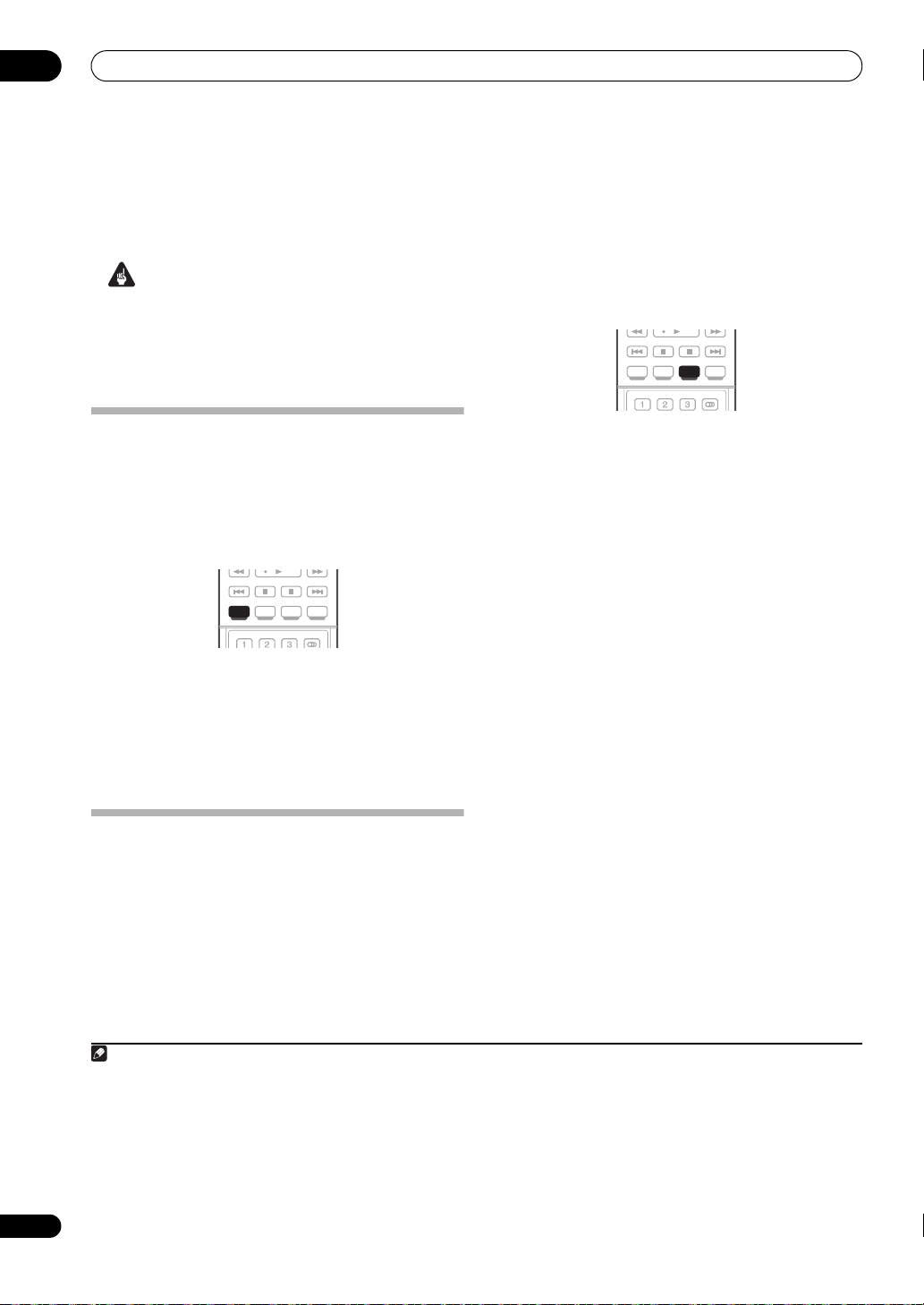
05
Listening to your system
Chapter 5:
Listening to your system
34
En
Important
• The listening modes and many features described in
this section may not be available depending on the
current source, settings and status of the amplifier.
See Listening modes with different input signal
formats on page 141 for more on this.
Auto playback
There are many ways to listen back to sources using this
amplifier, but for the simplest, most direct listening
option is the Auto Surround feature. The amplifier
automatically detects what kind of source you’re playing
and selects multichannel or stereo playback as
necessary.
• While listening to a source, press
AUTO SURROUND/STREAM DIRECT
(
playback of a source.
AUTO SURROUND shows briefly in the display before
showing the decoding or playback format. Check the
digital format indicators in the front LCD display to see
how the source is being processed.
1
THX
STEREO/
AUTO/
AUTO/
STANDARD ADV SUR R
F.S.SURR
DIRECT
DIRECT
SIGNAL SEL SLEEP AUDIODIMMER
AUTO/DIRECT
)2 for auto
Standard surround sound
The following modes provide basic surround sound for
stereo and multichannel sources.
THX
STEREO/
AUTO/
F.S.SURR
DIRECT
SIGNAL SEL SLEEP AUDIODIMMER
• While listening to a source, press
If necessary, press repeatedly to select a listening mode.
• If the source is Dolby Digital, DTS, or Dolby Surround
encoded, the proper decoding format will
automatically be selected and shows in the display.
With two channel sources, you can select from:
• 2 Pro Logic IIx MOVIE – Up to 7.1 channel sound,
especially suited to movie sources
• 2 Pro Logic IIx MUSIC – Up to 7.1 channel sound,
especially suited to music sources
• 2 Pro Logic IIx GAME– Up to 7.1 channel sound,
especially suited to video games
• 2 PRO LOGIC – 4.1 channel surround sound (sound
from the surround speakers is mono)
• Neo:6 CINEMA – 7.1 channel sound, especially
suited to movie sources
• Neo:6 MUSIC – 7.1 channel sound, especially suited
to music sources
6
3
STANDARD ADV SUR RSTANDARD
STANDARD
5
.
• Neural THX – Up to 7.1 channel sound, especially
Listening in surround sound
Using this amplifier, you can listen to any source in
surround sound. However, the options available will
depend on your speaker setup and the type of source
you’re listening to.
If you connected surround back speakers, see also Using
surround back channel processing on page 37.
suited to music sources
With multichannel sources, if you have connected
surround back speaker(s) and have selected SBch ON, you
can select (according to format):
• 2 Pro Logic IIx MOVIE – See above (only available
when you’re using two surround back speakers)
• 2 Pro Logic IIx MUSIC – See above
7
• Dolby Digital EX – Creates surround back channel
sound for 5.1 channel sources and provides pure
decoding for 6.1 channel sources (like Dolby Digital
Surround EX)
Note
1 • Stereo surround (matrix) formats are decoded accordingly using Neo:6 CINEMA or 2 Pro Logic IIx MOVIE (see Listening in surround sound above
for more on these decoding formats).
• The Auto Surround feature is canceled if you connect headphones.
2 For more options using this button, see Using Stream Direct on page 36.
3 In modes that give 6.1 channel sound, the same signal is heard from both surround back speakers.
4 If surround back channel processing (page 37) is switched OFF, or the surround back speakers are set to NO (this happens automatically if the Speaker
output setting on page 43 is set to All Ch Bi-Amp), 2 Pro Logic IIx becomes 2 Pro Logic II (5.2 channel sound).
5 When listening to 2-channel sources in Dolby Pro Logic IIx Music mode, there are three further parameters you can adjust: Center Width, Dimension,
and Panorama. See Setting the Audio options on page 99 to adjust them.
6 When listening to 2-channel sources in Neo:6 Music mode, you can also adjust the center image effect (see Setting the Audio options on page 99).
7 Neural THX can be selected when the input signal is an analog or PCM signal.
4
Page 35

Listening to your system
05
• DTS-ES – Allows you to hear 6.1 channel playback
with DTS-ES encoded sources
• DTS Neo:6 – Allows you to hear 6.1 channel playback
with DTS encoded sources
Using the Home THX modes
THX and Home THX are technical standards created by
THX Ltd. for cinema and home theater sound. Home THX
is designed to make home theater audio sound more like
what you hear in a cinema.
Different THX options will be available depending on the
source and the setting for surround back channel
processing (see Using surround back channel processing
on page 37 for more on this).
STATUS
SOURCE
SOURCE
TV AMP
TV AMP
VOLCH
VOL
1 Set the operation selector switch to
THX
2Press
to select a listening mode.
With two channel sources, press THX repeatedly to select
a matrix-decoding process for the THX CINEMA mode
(see Listening in surround sound on page 34 for an
explanation of each process):
• 2 Pro Logic IIx MOVIE+THX
• 2 PRO LOGIC+THX CINEMA
• Neo:6 CINEMA+THX
• 2 Pro Logic IIx MUSIC+THX
• Neo:6 MUSIC+THX
• 2 Pro Logic IIx GAME+THX
• THX Ultra2 GAMES
With multichannel sources, press THX repeatedly to
select from:
• THX Surround EX – Allows you to hear 6.1 or 7.1
channel playback with 5.1 channel sources
• 2 Pro Logic IIx MOVIE+THX
• THX Ultra2 CINEMA – Allows you to hear 7.1
channel playback with 5.1 channel sources
• 2 Pro Logic IIx MUSIC+THX
• THX Ultra2 MUSIC – This mode is suited not only for
sources recorded in Dolby Digital and DTS, but also
to all multi-channel music sources (DVD-Audio, etc.).
• THX Ultra2 GAMES – This mode is suited to playing
the sound of games.
THX
THX
AUTO/
DIRECT
STEREO/
F.S.SURR
CH LEVEL
STANDARD ADV SURR
AMP
1
.
Using the Advanced surround effects
The Advanced surround effects can be used for a variety
of additional surround sound effects. Most Advanced
Surround modes are designed to be used with film
soundtracks, but some modes are also suited for music
sources. Try different settings with various soundtracks
to see which you like.
THX
STEREO/
AUTO/
STANDARD ADV SUR RADV SURR
F.S.SURR
DIRECT
SIGNAL SEL SLEEP AUDIODIMMER
•Press
mode.
ADV SURR
2
repeatedly to select a listening
• ACTION – Designed for action movies with dynamic
soundtracks
• DRAMA – Designed for movies with lots of dialog
• SCI-FI – Designed for science fiction with lots of
special effects
• MONOFILM – Creates surround sound from mono
soundtracks
• ENTERTAINMENT SHOW – Suitable for musical
sources
• EXPANDED THEATER – Creates an extra wide stereo
3
field
• TV SURROUND – Provides surround sound for both
mono and stereo TV sources
• ADVANCED GAME – Suitable for video games
• SPORTS – Suitable for sports programs
• CLASSICAL – Gives a large concert hall-type sound
• ROCK/POP – Creates a live concert sound for rock
and/or pop music
• UNPLUGGED – Suitable for acoustic music sources
• EXTENDED STEREO – Gives multichannel sound to a
stereo source, using all of your speakers
• PHONES SURROUND – When listening through
headphones, you can still get the effect of overall
surround.
Tip
• When an Advanced Surround listening mode is
selected, the effect level can be adjusted using the
EFFECT parameter in Setting the Audio options on
page 99.
Note
1 • If you only have one surround back speaker connected, THX Ultra2 GAMES is not available.
• You can’t use the THX modes when headphones are connected.
2 • Depending on the source and the sound mode you have selected, you may not get sound from the surround back speakers in your setup. For more on
this, refer to Using surround back channel processing on page 37.
• If you press ADV SURR when the headphones are connected, the PHONES SURROUND mode will automatically be selected.
3 Use with Dolby Pro Logic for a stereo surround effect (stereo field is wider than Standard modes with Dolby Digital sources).
35
En
Page 36

05
Listening to your system
Listening in stereo
When you select STEREO, you will hear the source
through just the front left and right speakers (and
possibly your subwoofer depending on your speaker
settings). Dolby Digital, DTS and WMA9 Pro
multichannel sources are downmixed to stereo.
THX
STEREO/
STEREO/
AUTO/
STANDARD ADV SUR R
F.S.SURR
F.S.SURR
DIRECT
SIGNAL SEL SLEEP AUDIODIMMER
• While listening to a source, press
STEREO/F.S.SURR
for stereo playback.
Press repeatedly to switch between:
• STEREO – The audio is heard with your surround
settings and you can still use the Midnight,
Loudness, and Tone functions.
• F.S.SURR FOCUS – See Using Front Stage Surround
Advance below for more on this.
• F.S.SURR WIDE – See Using Front Stage Surround
Advance below for more on this.
Using Front Stage Surround Advance
The Front Stage Surround Advance function allows you to
create natural surround sound effects using just the front
speakers and the subwoofer.
THX
STEREO/
STEREO/
AUTO/
STANDARD ADV SUR R
F.S.SURR
F.S.SURR
DIRECT
SIGNAL SEL SLEEP AUDIODIMMER
• While listening to a source, press
to select Front Stage Surround Advance modes.
• STEREO – See Listening in stereo above for more on
this.
• F.S.SURR FOCUS – Use to provide a rich surround
sound effect directed to the center of where the front
left and right speakers sound projection area
converges.
• F.S.SURR WIDE – Use to provide a surround sound
effect to a wider area than FOCUS mode.
STEREO/F.S.SURR
1
FOCUS position
(Recommended)
Front left
speaker
Front right
speaker
WIDE position
Front left
speaker
Front right
Using Stream Direct
Use the Stream Direct modes when you want to hear the
truest possible reproduction of a source. All unnecessary
signal processing is bypassed, and you’re left with the
pure analog or digital sound source (see Stream direct
with different input signal formats on page 145).
THX
STEREO/
AUTO/
AUTO/
STANDARD ADV SURR
F.S.SURR
DIRECT
DIRECT
SIGNAL SEL SLEEP AUDIODIMMER
1 While listening to a source, press
(
AUTO SURROUND/STREAM DIRECT
mode you want.
Check the digital format indicators in the front LCD
display to see how the source is being processed.
• AUTO SURROUND – See Auto playback on page 34.
• DIRECT – Sources are heard according to the
settings made in the Surround Setup (speaker
setting, channel level, speaker distance, acoustic
calibration EQ, and X-curve), as well as with dual
mono, the input attenuator, and any sound delay and
hi-bit/hi-sampling settings. You will hear sources
according to the number of channels in the signal.
• PURE DIRECT – Analog and PCM sources are heard
without any digital processing.
output setting is set to 7.2ch + Speaker B, no sound
is output from the Speaker B in this mode.
AUTO/DIRECT
) to select the
2
When the speaker
speaker
36
En
Note
1 When using F.S.SURR WIDE, a better effect can be obtained if Auto MCACC Setup is performed. For more on this, refer to Automatically setting up for
surround sound (MCACC & Full Band Phase Control) on page 11.
2 There are cases where a brief noise is heard before playback of sources other than PCM. Please select AUTO SURROUND or DIRECT if this is a problem.
Page 37

Listening to your system
F.S.SURR
DIRECT
STANDARD ADV SURR
05
Selecting MCACC presets
• Default setting: MEMORY 1
If you have calibrated your system for different listening
1
positions
, you can switch between settings to suit the
kind of source you’re listening to and where you’re sitting
(for example, watching movies from a sofa, or playing a
video game close to the TV).
A.ATT GENRE
HDMI OUT
SOURCE
SOURCE
TV AMP
TV AMP
VOLCH
VOL
1 Set the operation selector switch to
2 While listening to a source, press
MCACCCHMCACC
CLR
ENTER
AMP
.
MCACC
.
Press repeatedly to select one of the six MCACC presets2
or to switch calibration off. See Data Management on
page 50 to check and manage your current settings.
Choosing the input signal
On this amplifier, it is possible to switch the input signals
for the different inputs as described below.
SOURCE
SOURCE
TV AMP
TV AMP
VOLCH
VOL
SIGNAL SEL SLEEP AUDIODIMMER
SIGNAL SEL
SR+ SBch PHASE iPod CTRL
1 Set the operation selector switch to
2Press
SIGNAL SEL (SIGNAL SELECT
input signal corresponding to the source component.
Each press cycles through the options as follows:
• AUTO – This is the default setting. The amplifier
selects the first available signal in the following order:
; HDMI; 2 RF; DIGITAL; ANALOG.
• ANALOG – Selects an analog signal.
• DIGITAL – Selects an optical or coaxial digital signal.
3
DISP
AMP
.
) to select the
• 2 RF – Selects a 2 RF signal.
• HDMI – Selects an HDMI signal.
4
5
• – Selects an i.LINK signal.
• PCM – Only PCM signals are output.
6
The amplifier
selects the first available signal in the following order:
; HDMI; DIGITAL.
Using surround back channel
processing
• Default setting: SBch ON
You can have the amplifier automatically use 6.1 or 7.1
decoding for 6.1 encoded sources (for example, Dolby
Digital EX or DTS-ES), or you can choose to always use
6.1 or 7.1 decoding (for example, with 5.1 encoded
material). With 5.1 encoded sources, a surround back
channel will be generated, but the material may sound
better in the 5.1 format for which it was originally
encoded (in which case, you can simply switch surround
back channel processing off).
The table below indicates when you will hear the
surround back channel when playing various kinds of
sources (
speaker(s)).
=Sound plays through surround back
SIGNAL SEL SLEEP AUDIODIMMER
SOURCE
SOURCE
TV AMP
TV AMP
VOLCH
SR+
SBch PHASE iPod CTRL
SBch
DISP
HDMI OUT
A.ATT GENRE
VOL
CH
Note
1 Different presets might also have separate calibration settings for the same listening position, depending on how you’re using your system. These presets
can be set in Automatically setting up for surround sound (MCACC & Full Band Phase Control) on page 11 or Automatic MCACC (Expert) on page 40, either
of which you should have already completed.
2 • These settings have no effect when headphones are connected.
• You can also press / to select the MCACC preset.
3 • This amplifier can only play back Dolby Digital, PCM (32 kHz to 192 kHz), DTS (including DTS 96 kHz / 24 bit) and WMA9 Pro digital signal formats. The
compatible signals via the HDMI and i.LINK terminals are: Dolby Digital, DTS, WMA 9 Pro, PCM (32 kHz, 44.1 kHz, 88.2 kHz and 96 kHz sampling
frequencies), Dolby TrueHD, Dolby Digital Plus, DTS-EXPRESS, DTS-HD Master Audio, SACD and DVD Audio (including 192 kHz). With other digital signal
formats, set to ANALOG (the MULTI CH IN, TUNER and PHONO).
• You may get digital noise when a LD or CD player compatible with DTS is playing an analog signal. To prevent noise, make the proper digital connections
(page 25) and set the signal input to DIGITAL.
• Some DVD players don’t output DTS signals. For more details, refer to the instruction manual supplied with your DVD player.
• Even when i.LINK is selected and the i.LINK indicator lights, you won’t hear any sound if the ouput settings of your i.LINK device are off.
• The input signal for unassigned i.LINK-equipped components is fixed to . See Checking the i.LINK inputs on page 59.
4 Make sure you connect your DVD/LD or LD players using the RF IN jack. If your player has a 2 RF output this will ensure you can use all LDs. Refer to
Connecting your TV and DVD player on page 20.
5 When the HDMI option in Setting the Audio options on page 99 is set to THROUGH, the sound will be heard through your TV, not from this amplifier.
6 • This is useful if you find there is a slight delay before AUTO recognizes the PCM signal on a CD, for instance.
• When PCM is selected, noise may be output during playback of non-PCM sources. Please select another input signal if this is a problem.
37
En
Page 38

05
Listening to your system
1 Set the operation selector switch to
2 Press
channel options.
SBch
repeatedly to cycle the surround back
1
Each press cycles through the options as follows:
• SBch ON – 6.1 or 7.1 decoding is always used (for
example, a surround back channel will be generated
for 5.1 encoded material)
• SBch AUTO – Automatically switches to 6.1 or 7.1
decoding for 6.1 encoded sources (for example,
Dolby Digital EX or DTS-ES)
• SBch OFF – No sound is output from the surround
back speakers
AMP
.
Using the Virtual Surround Back mode
When you’re not using surround back speakers,
selecting this mode allows you to hear a virtual surround
back channel through your surround speakers. You can
choose to listen to sources with no surround back
channel information, or if the material sounds better in
the format (for example, 5.1) for which it was originally
encoded, you can have the amplifier only apply this effect
to 6.1 encoded sources like Dolby Digital EX or DTS-ES.
The table indicates when you will hear the virtual
surround back channel (
channel is active).
• Press
back channel options.
Each press cycles through the options as follows:
• VirtualSB ON – Virtual Surround Back is always used
(for example, on 5.1 encoded material)
• VirtualSB AUTO – Virtual Surround Back is
automatically applied to 6.1 encoded sources (for
example, Dolby Digital EX or DTS-ES)
• VirtualSB OFF – Virtual Surround Back mode is
switched off
SBch
Type of source
Dolby Digital EX/DTS-ES 5.1 ch sources
with 6.1 ch flagged
Dolby Digital/DTS and DVD-Audio 5.1 ch
sources
Dolby Digital/DTS/PCM and DVD-Audio
stereo sources
Analog 2-channel (stereo) sources ON
DTS-HD Master Audio/DTS-HD/Dolby
Digital Plus/Dolby TrueHD/WMA9 Pro
encoded and PCM 6.1 ch/7.1 ch sources
Dolby Digital Plus/Dolby TrueHD/WMA9
Pro (44.1 kHz/48 kHz) encoded and PCM
5.1 ch sources
DTS-HD Master Audio/DTS-HD/
DTS-EXPRESS/WMA9 Pro (88.2 kHz/96
kHz) encoded 5.1 ch sources
Processing /
Virtual SB
mode
ON
AUTO
ON
AUTO
ON
AUTO
AUTO
ON
AUTO
ON
AUTO
ON
AUTO
Multichannel
sources
c
c
c
c
2
Pro Logic IIx
SBch
repeatedly to cycle the virtual surround
Standard / THX
Stereo sources
2 Pro Logic Neo:6
b
b
=Virtual surround back
a
a
Advanced
surround
d
d
d
d
d
d
2
38
En
Note
1 By using a combination of surround back channel processing selection with speaker system selection it is possible to switch between a speaker
configuration for high sound quality multi-channel music sources (DVD Audio discs, SACDs, etc.) and the speaker configuration recommended by THX for
viewing movies. For details, see Switching the speaker system according to the playback environment (Application Manual) on page 62.
2 • You can’t use the Virtual Surround Back mode when the headphones are connected to this amplifier or when any of the THX, stereo, Front Stage
Surround Advance or Stream Direct mode is selected.
• You can only use the Virtual Surround Back mode if the surround speakers are on and the SB setting is set to NO in the Speaker Setting on page 52 or
All Ch Bi-Amp is selected in the Speaker output setting on page 43.
• The Virtual Surround Back mode cannot be applied to sources that do not have surround channel information.
Page 39

Listening to your system
05
SBch
Type of source
Dolby Digital Plus/Dolby TrueHD/WMA9
Pro (44.1 kHz/48 kHz) encoded stereo
sources
DTS-HD Master Audio/DTS-HD/
DTS-EXPRESS/WMA9 Pro (88.2 kHz/96
kHz) encoded stereo sources
a. Only applicable when using the Virtual Surround Back mode.
b. Not applicable when using the Virtual Surround Back mode.
c. Sound is output from the surround back speakers only when THX Ultra2 CINEMA, THX MUSIC or THX GAMES is selected.
d. Advanced surround mode may not be available depending on the input signal.
Processing /
Virtual SB
mode
Multichannel
sources
ON
AUTO
ON
AUTO
2
Pro Logic IIx
Standard / THX
Stereo sources
2 Pro Logic Neo:6
b
a
Using the genre synchronizing function
This feature automatically selects the most appropriate
Advanced Surround mode for the source currently being
played back on a Pioneer DVD recorder supporting HDMI
Control connected to this amplifier via HDMI.
on HDMI Control, see About HDMI on page 19.
SR+
SBch PHASE iPod CTRL
SOURCE
SOURCE
TV AMP
TV AMP
VOLCH
VOL
GENRE
A.ATT GENRE
MCACC
CLR
1 Set the operation selector switch to
2Press
GENRE
while the source assigned to a genre
is being played back.
The most appropriate Advanced Surround mode for the
source being played back is automatically selected.
HDMI OUT
ENTER
1
For details
DISP
CH
AMP
.
Advanced
surround
d
d
Note
1 • This feature is available only when the source being played back is assigned to a genre. When the source has no genre assigned to, NO GENRE appears
showing that this feature is not available.
• Make sure that HDMI Control is set to ON. When OFF is selected, CANNOT SELECT appears showing that this feature is not available (see About HDMI
on page 19).
39
En
Page 40

06
The System Setup menu
Chapter 6:
The System Setup menu
• Auto MCACC – See Automatically setting up for
Making amplifier settings from the
System Setup menu
The following section shows you how to make detailed
settings to specify how you’re using the amplifier (for
example, if you want to set up two speaker systems in
separate rooms), and also explains how to fine-tune
individual speaker system settings to your liking.
SOURCE
SOURCE
AMP
TV AMP
MAIN
AV AMPLIFIER
DVD
DVR1
HOME MEDIA
GALLERY
TUNER
ZONE2 3
MULTI
OPERATION
BD TV SAT
VIDEO1
DVR2
CD
SACD
iPod HDMI
PHONO
INPUT SELECT
SOURCE
VIDEO2
CD-R
1 Switch on the amplifier and your TV.
Use the AV AMPLIFIER button to switch on.
• If headphones are connected to the amplifier,
disconnect them.
2 Set the operation selector switch to
press the
SETUP
button.
2
An on-screen display (OSD) appears on your TV. Use the
/// buttons and ENTER to navigate through the
screens and select menu items. Press RETURN to
confirm and exit the current menu.
• Press SETUP at any time to exit the System Setup
menu.
3 Select the setting you want to adjust.
DVD/LD
System Setup MENU
1. Auto MCACC
2. Output Setup
3. Manual MCACC
4. FULL BAND PHASE CTRL
5. Data Management
6. Manual SP Setup
7. Input Setup
8. OSD Language
9. Other Setup
TV
CH
VOL
TV CONTROL
INPUT MUTE MUTE
AUDIO
PARAMETER
TOP MENU
ENTER
ENTER
SETUP
SETUP
SETUP
STATUS CH LEVEL
-
55.0
dB
:Exit
VOL
VIDEO
PARAMETER
MENU
RETURN
RETURN
AMP
1
, then
surround sound (MCACC & Full Band Phase Control)
on page 11 for a quick and effective automatic
surround setup. See Automatic MCACC (Expert)
below for a more detailed setup.
• Output Setup – Specifies how you are using your
speaker terminals (see Speaker output setting on
page 43).
• Manual MCACC – Fine-tunes your speaker settings
and customize the Acoustic Calibration EQ (see
Manual MCACC setup on page 44).
• FULL BAND PHASE CTRL – Calibrates and
automatically corrects the frequency-phase
characteristics of the speakers connected (see Full
Band Phase Control on page 49).
• Data Management – Checks your MCACC presets
and manages them through copying, renaming or
deleting (see Data Management on page 50).
• Manual SP Setup – Specifies the size, number,
distance and overall balance of the speakers you’ve
connected (see Manual speaker setup on page 52).
• Input Setup – Specifies what you’ve connected to
the digital, HDMI, component video and S-Video
inputs (see The Input Setup menu on page 94).
• OSD Language – The OSD’s display language can
be changed (see Changing the OSD display language
(OSD Language) on page 95).
• Other Setup – Makes customized settings to reflect
how you are using the amplifier (see The Other Setup
menu on page 96).
Automatic MCACC (Expert)
If your setup requires more detailed settings than those
provided in Automatically setting up for surround sound
(MCACC & Full Band Phase Control) on page 11, you can
customize your setup options below. You can calibrate
your system differently for up to six different MCACC
3
presets
positions depending on the type of source (for example,
watching movies from a sofa, or playing a video game
close to the TV).
, which are useful if you have different listening
4
40
En
Note
1 Make sure not to switch off the power when using the System Setup menu.
2 • Note that when editing items in the Manual MCACC menu, you will need to first specify the MCACC preset you want to adjust by pressing MCACC
before pressing SETUP
• When the iPod or HOME MEDIA GALLERY input source is selected (in either the main or sub zone), or when using headphones, you can’t use the
System Setup menu. When you set ZONE 2, ZONE 3 or ZONE 2&3 to ON (page 66), you can’t use the System Setup menu.
3 These are stored in memory and referred to as MEMORY1 to MEMORY6 until you rename them in Data Management on page 50.
4 You may also want to have separate calibration settings for the same listening position, depending on how you’re using your system.
.
Page 41
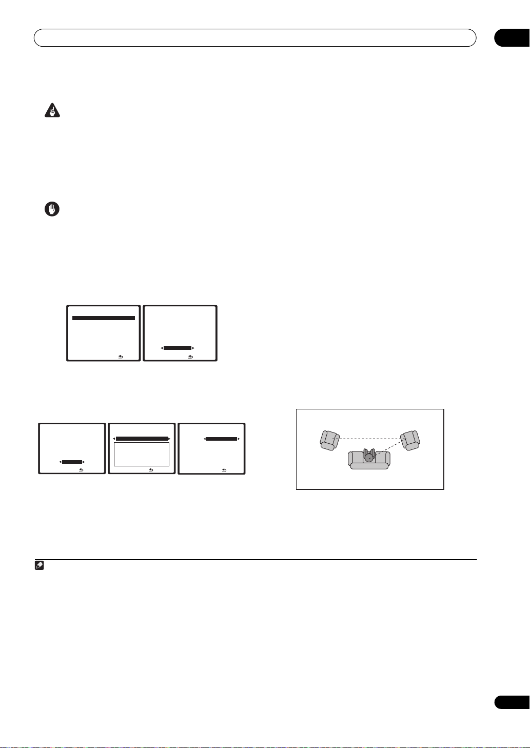
The System Setup menu
06
Important
• Make sure the microphone/speakers are not moved
during the Auto MCACC Setup.
• Using the Auto MCACC Setup will overwrite any
existing settings for the MCACC preset you select.
1
• The screen saver will automatically appear after three
minutes of inactivity.
Caution
• The test tones used in the Auto MCACC Setup are
output at high volume.
1 Select ‘
then press
Auto MCACC
ENTER
.
’ from the System Setup menu,
If the System Setup screen is not displayed, refer to
Making amplifier settings from the System Setup menu on
page 40.
DVD/LD
System Setup MENU
1. Auto MCACC
2. Output Setup
3. Manual MCACC
4. FULL BAND PHASE CTRL
5. Data Management
6. Manual SP Setup
7. Input Setup
8. OSD Language
9. Other Setup
2 Make sure ‘
3
, then select
preset
DVD/LD
-
55.0
dB
1. Auto MCACC
Output Setup
[ Normal ]
Save SYMMETRY to
[ M1. MEMORY 1 ]
START
:Exit
ENTER:Start :Cancel
Normal
’ is selected,2 select an MCACC
4
START
.
-
55.0
dB
For a fully customized Auto MCACC setup, select
CUSTOM and set the following parameters using /:
DVD/LD
1. Auto MCACC
Output Setup
[ Normal ]
Save SYMMETRY to
[ M1. MEMORY 1 ]
CUSTOM
ENTER:Next
: Cancel
dB
DVD/LD
1. Auto MCACC
Custom Menu
ALL
Speaker Setting
Channel Level
Speaker Distance
EQ Pro. & S-Wave
FULL BAND PHASE CTRL
ENTER:Next
-
55.0
: Return
dB
DVD/LD
1. Auto MCACC
SYMMETRY
M1.MEMORY 1
ALL CH ADJ
[ M2.MEMORY 2 ]
FRONT ALIGN
[ M3.MEMORY 3 ]
THX Speaker [ NO ]
[ START ]
-
: Return
55.0
dB
-
55.0
• Custom Menu – The default is ALL (recommended),
but you can limit the system calibration to only one
setting (to save time) if you want.
options are ALL, Keep SP System,
6
The available
7
Speaker
Setting, Channel Level, Speaker Distance and EQ
Pro. & S-Wave.
• EQ Type (only available when the Custom Menu
above is EQ Pro. & S-Wave) – This determines how
the frequency balance is adjusted.
After a single calibration is performed, each of the
following three correction curves can be stored
separately in the MCACC memory. SYMMETRY (default)
implements symmetric correction for each pair of left
and right speakers to flatten the frequency-amplitude
characteristics. ALL CH ADJUST is a ‘flat’ setting where
all the speakers are set individually so no special
weighting is given to any one channel. FRONT ALIGN
sets all speakers in accordance with the front speaker
settings (no equalization is applied to the front left and
right channels).
• THX Speaker (only available when the Custom Menu
above is ALL or Speaker Setting) – Select YES if you
are using THX speakers (set all speakers to SMALL),
otherwise leave it set to NO.
• Stand.Wave Multi-Point (only available when the
Custom Menu above is EQ Pro. & S-Wave) – In
addition to measurements at the listening position,
you can use two more reference points for which test
tones will be analyzed for standing waves. This is
useful if you want to get a balanced ‘flat’ calibration
for several seating positions in your listening area.
Place the microphone at the reference point
indicated on-screen and note the last microphone
placement will be at your main listening position:
5
2nd reference
point
12
Main listening
position
3
3rd reference
point
When you’re finished settings the options, press
RETURN to go back to the Auto MCACC main setup.
8
9
Note
1 Except in cases where you are only adjusting one parameter (i.e. channel level) from the CUSTOM setup screen (step 2).
2 If you are planning to select any options other than Normal, read through Speaker output setting on page 43 and make sure to connect your speakers as
necessary before continuing to step 3.
3 The six MCACC presets are used for storing surround sound settings for different listening positions. Simply choose an unused preset for now (you can
rename it later in Data Management on page 50).
4 Note that correction curves are saved only when set to SYMMETRY. Select CUSTOM to save other correction curves (such as ALL CH ADJUST and
FRONT ALIGN).
5 Select DEMO, and then press ENTER to activate the demo mode of Auto MCACC. In the demo mode, no settings are saved and no errors occur. When
the speakers are connected to this amplifier, the test tone is output repeatedly. Press RETURN to cancel the test tone.
6• The EQ Pro. & S-Wave measurement is also taken when ALL is selected. See Acoustic Calibration EQ Professional on page 47 for more on this.
• Either effect of Acoustic Calibration EQ Professional and Standing Wave can be switched on and off in the respective MCACC preset. For details, see
Setting the Audio options on page 99.
• The FULL BAND PHASE CTRL measurement is also taken when ALL is selected. See Full Band Phase Control on page 49.
7The Keep SP System option allows you to calibrate your system while leaving your current speaker setting (page 52) unchanged.
8 If you selected ALL as your Custom Menu, you can specify the MCACC preset where you want to save the ALL CH ADJUST and FRONT ALIGN settings.
9 Switch the Multi-Point setting NO if you only use one listening position.
41
En
Page 42

06
The System Setup menu
3 Connect the microphone to the
MCACC SETUP MIC
jack on the front panel.
Make sure there are no obstacles between the speakers
and the microphone.
ZONE2 ZONE3
CTRL
MULTI-ZONE CONTROL
SPEAKERS AUTO SURROUND
/STREAM DIRECT
PARAMETER
AUDIO VIDEO
ENTER
MCACC
MCACC
PHONES
SETUP MIC
SETUP MIC
SETUP
RETURN
USB
VIEW
STATUS
DIMMER
VIDEO/GAME 2 INPUT
DIGITAL INS-VIDEO VIDEO L R
AUDIO
LCD
If you have a tripod, use it to place the microphone so that
it’s about ear level at your normal listening position.
Otherwise, place the microphone at ear level using a
table or a chair.
4 Follow the instructions on-screen.
• Make sure the microphone is connected.
• If you’re using a subwoofer, it is automatically
detected every time you switch on the system. Make
sure it is on and the volume is turned up.
• See Problems when using the Auto MCACC Setup on
page 13 for notes regarding high background noise
levels and other possible interference.
5 Wait for the Auto MCACC Setup to finish
outputting test tones.
A progress report is displayed on-screen while the
amplifier outputs test tones to determine the speakers
present in your setup. Try to be as quiet as possible while
it’s doing this.
• Do not adjust the volume during the test tones. This
may result in incorrect speaker settings.
• With error messages (such as Too much ambient
noise! or Check Microphone) select RETRY after
checking for ambient noise (see Problems when
using the Auto MCACC Setup on page 13) and
verifying the mic connection. If there doesn’t seem to
be a problem, you can simply select GO NEXT and
continue.
6 If necessary, confirm the speaker configuration in
the OSD.
1
The configuration shown on-screen should reflect the
actual speakers you have.
If no operations are performed for 10 seconds while the
speaker configuration check screen is being displayed,
the Auto MCACC Setup will resume automatically. In this
case, you don’t need to select ‘OK’ and press ENTER in
step 7.
DVD/LD 0.0
1. Auto MCACC
Now Analyzing… ( 2/10)
Environment Check
Ambient Noise [ OK ]
Microphone [ ]
Speaker YES/NO [ ]
dB
:Cancel
DVD/LD 0.0
1. Auto MCACC
CHECK
Front [ YES ]
Center [ YES ]
Surr A [ YES ]
Surr B [ YES ]
SB [ YESx2 ]
SW [ YESx2 ]
OK
10:Next
:Cancel
If you see an error message (ERR) in the right side
column (or the speaker configuration displayed isn’t
correct), there may be a problem with the speaker
connection. If selecting RETRY doesn’t work, turn off the
power and check the speaker connections. If there
doesn’t seem to be a problem, you can simply use /
to select the speaker and / to change the setting
(and number for surround back) and continue.
7 Make sure ‘OK’ is selected, then press
ENTER
A progress report is displayed on-screen while the
amplifier outputs more test tones to determine the
optimum amplifier settings for channel level, speaker
distance, and Acoustic Calibration EQ.
DVD/LD
1. Auto MCACC
Now Analyzing
Subwoofer Check
…
0.0
:Cancel
DVD/LD
dB
1. Auto MCACC
Now Analyzing… ( 6/10)
Surround Analysis
Speaker System [ OK ]
Channel Level [ OK ]
Speaker Distance [ ]
-
55.0
:Cancel
Again, try to be as quiet as possible while this is
happening. It may take 3 to 7 minutes.
• If you selected a Stand.Wave Multi-Point setup (in
step 2), you will be asked to place the mic at the 2nd
and 3rd reference points before finally placing it at
your main listening position.
8 The Auto MCACC Setup has finished! Press
to go back to the System Setup menu.
DVD/LD
5a. MCACC Data Check
1. Speaker Setting
2. Channel Level
3. Speaker Distance
4. Standing Wave
5. Acoustic Cal EQ
6. FULL BAND PHASE CTRL
ENTER:Next
-
55.0
:Return
dB
dB
.
dB
RETURN
42
En
Note
1 This screen is only shown if you selected ALL or Speaker System in Custom Menu from the Auto MCACC CUSTOM menu.
Page 43

The System Setup menu
The settings made in the Auto MCACC Setup should give
you excellent surround sound from your system, but it is
also possible to adjust these settings manually using the
System Setup menu (starting on page 40).
You can also choose to view the settings by selecting
individual parameters from the MCACC Data Check
screen:
• Speaker Setting – The size and number of speakers
you’ve connected (see page 52 for more on this)
• Channel Level – The overall balance of your speaker
system (see page 44 or 53 for more on this)
• Speaker Distance – The distance of your speakers
from the listening position (see page 45 or 54 for
more on this)
2
• Standing Wave – Filter settings to control lower
‘boomy’ frequencies (see page 46 for more on this)
• Acoustic Cal EQ – Adjustments to the frequency
balance of your speaker system based on the
acoustic characteristics of your room (see page 47
for more on this)
• FULL BAND PHASE CTRL – The original
characteristics of group delay of the speakers
calibrated and the targeted characteristics can be
displayed graphically (see Full Band Phase Control on
page 49 for more on this).
Press ENTER after you have finished checking each
screen. When you’re finished, select RETURN to go back
to the System Setup menu.
Be sure to disconnect the microphone from this amplifier
upon completion of the Auto MCACC setup.
1
Speaker output setting
• Default setting: Normal
You can set the usage purpose for the ten channels worth
of speaker terminals. One of five patterns can be selected
according to the speaker layout and usage purpose (see
Selecting the speaker layout/usage pattern on page 9).
1Select ‘
Output Setup
’ from the System Setup
menu.
See Making amplifier settings from the System Setup
menu on page 40 if you’re not already at this screen.
DVD/LD
System Setup MENU
1. Auto MCACC
2. Output Setup
3. Manual MCACC
4. FULL BAND PHASE CTRL
5. Data Management
6. Manual SP Setup
7. Input Setup
8. OSD Language
9. Other Setup
-
:Exit
55.0
dB
DVD/LD
2. Output Setup
Normal
Front :Normal
Center :Normal
Surr :Array
SB :Normal
[ Confirm ]
---
:Cancel
The amplifier’s volume is set to the minimum in order to
protect the speakers.
2 Select the speaker setting.
• Normal – Select for “Normal surround connections”.
• All Ch Bi-Amp – Select for “5.2-channel Bi-amp
connections”.
• Front Bi-Amp – Select for “7.2-channel front Bi-amp
connections”.
• 7.2ch+ZONE 2 – Select for “7.2-channel + Zone 2
connections”.
• 7.2ch+Speaker B – Select for “7.2-channel + speaker
B connections”.
3Select ‘
Confirm
’.
The layout of the speaker terminals for the selected item
is displayed.
4 Check the layout of the output terminals, then
select ‘
YES
’.
The setting is made according to the selected item.
5 When you’re finished, press
RETURN
.
You will return to the System Setup menu.
3
dB
06
Note
1 • Depending on the characteristics of your room, sometimes identical speakers with cone sizes of around 12 cm will end up with different size settings.
You can correct the setting manually using the Manual speaker setup on page 52.
• The subwoofer distance setting may be farther than the actual distance from the listening position. This setting should be accurate (taking delay and
room characteristics into account) and generally does not need to be changed.
• If Auto MCACC Setup measurement results are incorrect due to the interaction of the speakers and viewing environment, we recommend adjusting
the settings manually.
2 Since the distance measurements have been set according to the sound characteristics of your speakers, there are cases where (for optimal surround
sound) the actual distance may differ from the speaker distance setting.
3 • When changing the speaker output settings, we recommend selecting the speaker layout/usage pattern first.
• All the MCACC memory settings are cleared when the speaker output settings are changed. Perform the Auto MCACC Setup procedure again after
changing the speaker connections and speaker output settings (see page 11).
43
En
Page 44

06
The System Setup menu
Manual MCACC setup
You can use the settings in the Manual MCACC setup
menu to make detailed adjustments when you’re more
familiar with the system. Before making these settings,
you should have already completed Automatically setting
up for surround sound (MCACC & Full Band Phase Control)
on page 11.
You only need to make these settings once (unless you
change the placement of your current speaker system or
add new speakers).
Caution
• The test tones used in the System Setup are output at
high volume.
Important
• You will need to first specify the MCACC preset you
want to adjust by pressing MCACC before pressing
SETUP (step 2 in Making amplifier settings from the
System Setup menu on page 40). When Manual
MCACC is selected while MCACC is set to OFF, the
selection screen for the MCACC memory appears.
Select a memory to adjust manually.
DVD/LD
3. Manual MCACC
Select MCACC memory.
MCACC OFF
M1. MEMORY 1
ENTER:Next
• For some of the settings below, you’ll have to connect
the setup microphone to the front panel and place it
about ear level at your normal listening position.
Press SETUP to display the System Setup menu
before you connect the microphone to this amplifier.
If the microphone is connected while the System
Setup menu is not being displayed, the display will
change to the Auto MCACC setup menu. See
Problems when using the Auto MCACC Setup on
page 13 for notes regarding high background noise
levels and other possible interference.
• If you’re using a subwoofer, switch it on and turn up
the volume to the middle position.
1 Select ‘
Manual MCACC
menu.
See Making amplifier settings from the System Setup
menu on page 40 if you’re not already at this screen.
DVD/LD
System Setup MENU
1. Auto MCACC
2. Output Setup
3. Manual MCACC
4. FULL BAND PHASE CTRL
5. Data Management
6. Manual SP Setup
7. Input Setup
8. OSD Language
9. Other Setup
-
55.0
:Exit
-
55.0
dB
:Cancel
’ from the System Setup
-
55.0
DVD/LD
dB
3. Manual MCACC
a . Fine Channel Level
b . Fine SP Distance
c . Precision Distance
d . Standing Wave
e . EQ Adjust
f . EQ Professional
dB
:Return
2 Select the setting you want to adjust.
If you’re doing this for the first time, you might want to
make these settings in order.
• Fine Channel Level – Make fine adjustments to the
overall balance of your speaker system (see Fine
Channel Level below).
• Fine SP Distance – Make precise delay settings for
your speaker system (see Fine Speaker Distance on
page 45).
• Precision Distance – Fine-adjusting the positions of
the speakers (see Fine-adjusting the positions of the
speakers (Precision Distance) on page 45).
• Standing Wave – Control overly resonant low
frequencies in your listening room (see Standing
Wave on page 46).
The last two settings are specifically for customizing the
parameters explained in Acoustic Calibration EQ Adjust
on page 47:
• EQ Adjust – Manually adjust the frequency balance
of your speaker system while listening to test tones
(see Acoustic Calibration EQ Adjust on page 47).
• EQ Professional – Calibrate your system based on
the direct sound coming from the speakers and make
detailed settings according to your room’s reverb
characteristics (see Acoustic Calibration EQ
Professional on page 47).
Fine Channel Level
• Default setting: 0.0dB (all channels)
You can achieve better surround sound by properly
adjusting the overall balance of your speaker system. The
following setting can help you make detailed
adjustments that you may not achieve using the Manual
speaker setup on page 52.
1 Select ‘
setup menu.
The volume increases to the 0.0 dB reference level.
Fine Ch Level
DVD/LD
3. Manual MCACC
a . Fine Channel Level
b . Fine SP Distance
c . Precision Distance
d . Standing Wave
e . EQ Adjust
f . EQ Professional
’ from the Manual MCACC
-
55.0
dB
:Return
DVD/LD
3a. Fine Channel Level
Please wait... 20
CAUTION
Loud test tones will
be output.
-
:Cancel
20.0
dB
44
En
Page 45

The System Setup menu
06
2 Adjust the level of the left channel.
This will be the reference speaker level, so you may want
to keep the level around 0.0dB so that you’ll have plenty
of room to adjust the other speaker levels.
DVD/LD
3a. Fine Channel Level
MCACC : M1. MEMORY 1
Ref.Ch : L
+0.5dB
ENTER:Next :Cancel
0.0
dB
• After pressing ENTER, test tones will be output.
3 Select each channel in turn and adjust the levels
(
+/–10dB
) as necessary.
Use / to adjust the volume of the speaker you
selected to match the reference speaker. When it sounds
like both tones are the same volume, press to confirm
and continue to the next channel.
DVD/LD
3a. Fine Channel Level
SL A L
L +0.5dB
R [ -1.5dB]
C [ +1.0dB]
SL A +10.0dB
SR
A [ +10.0dB]
SL B [ -10.0dB]
SR
B [ +10.0dB]
0.0
SBL [ -9.5dB]
SBR [ +10.0dB]
SW1 [ -1.5dB]
SW2 [ -1.5dB]
: Finish
dB
• For comparison purposes, the reference speaker will
change depending on which speaker you select.
• If you want to go back and adjust a channel, simply
use / to select it.
4 When you’re finished, press
RETURN
.
You will return to the Manual MCACC setup menu.
Fine Speaker Distance
• Default setting: 3.00 m (all speakers)
For proper sound depth and separation with your system,
it is necessary to add a slight bit of delay to some
speakers so that all sounds will arrive at the listening
position at the same time. You can adjust the distance of
each speaker in 1 cm increments. The following setting
can help you make detailed adjustments that you may
not achieve using the Manual speaker setup on page 52.
1 Select ‘
setup menu.
Fine SP Distance
DVD/LD
3. Manual MCACC
a . Fine Channel Level
b . Fine SP Distance
c . Precision Distance
d . Standing Wave
e . EQ Adjust
f . EQ Professional
-
:Return
’ from the Manual MCACC
55.0
dB
DVD/LD
3b. Fine SP Distance
MCACC : M1. MEMORY 1
Ref.Ch : L
3.03 m
ENTER:Next :Cancel
0.0
dB
2 Adjust the distance of the left channel from the
listening position.
3 Select each channel in turn and adjust the distance
as necessary.
Use / to adjust the delay of the speaker you selected
to match the reference speaker. The delay is measured in
terms of speaker distance from 0.01 m to 9.00 m.
DVD/LD
3b. Fine SP Distance
C L
L [ 3.05 m]
R [ 2.81 m]
C 1.92 m]
SL A [ 2.23 m]
SR
A [ 2.34 m]
SL B [ 3.24 m]
SR
B [ 3.36 m]
:Finish
0.0
dB
DVD/LD
3b. Fine SP Distance
SBL SL A
SBL 2.52 m
SBR [
SW1 [
SW2 [
:Finish
2.32 m]
4.02 m]
4.13 m]
0.0
dB
Listen to the reference speaker and use it to measure the
target channel. From the listening position, face the two
speakers with your arms outstretched pointing at each
speaker. Try to make the two tones sound as if they are
arriving simultaneously at a position slightly in front of
you and between your arm span.
1
When it sounds like the delay settings are matched up,
press to confirm and continue to the next channel.
• For comparison purposes, the reference speaker will
change depending on which speaker you select.
• If you want to go back and adjust a channel, simply
use / to select it.
4 When you’re finished, press
RETURN
.
You will return to the Manual MCACC setup menu.
Fine-adjusting the positions of the speakers
(Precision Distance)
Before using this function, perform the Auto MCACC
Setup procedure (see page 11). The auto MCACC speaker
distance correction function corrects the distance to the
speakers with a precision of 1 cm. Here, rather than
correct the numerical value of the distance, actually
move the physical positions of the speakers to fine-adjust
(the subwoofer cannot be adjusted). The input from the
microphone is indicated on the screen. Fine-adjust the
positions of the speakers so that the gauge reading is
maximum. The detailed distance adjustments that were
previously performed by skilled installers by ear can
easily be performed watching the gauge on the monitor.
Note
1 • If you can’t seem to achieve this by adjusting the distance setting, you may need to change the angle of your speakers very slightly.
• For better audibility, the subwoofer emits a continuous test tone (oscillating pulses are heard from your other speakers). Note that it may be difficult to
compare this tone with the other speakers in your setup (depending on the low frequency response of the reference speaker).
45
En
Page 46

06
The System Setup menu
1 Select ‘
Precision Distance
’ from the Manual
MCACC setup menu.
Determine this after connecting the setup microphone.
-
55.0
:Return
dB
DVD/LD
3c. Precision Distance
Please wait... 20
CAUTION
Loud test tones will
be output.
-
20.0
:Cancel
dB
DVD/LD
3. Manual MCACC
a . Fine Channel Level
b . Fine SP Distance
c . Precision Distance
d . Standing Wave
e . EQ Adjust
f . EQ Professional
2 Fine-adjust the positions of the speakers in
sequence, starting from the front right channel.
1
Test tones are output from the speaker for the selected
channel and from one other speaker. Move the position
of the selected speaker to fine-adjust. Watch the screen
when doing so, and fine-adjust the positions of the
speakers so that the gauge reading is maximum. Also,
the channel serving as the standard differs according to
the channel being adjusted. Do not move the speaker
serving as the standard channel.
The maximum gauge reading is 10.0. (If the reading stays
under 10.0, adjust the speaker for the maximum value.)
DVD/LD
3c. Precision Distance
Ref . Ch : L
Ch R
9.2
Adjust speaker
position
: Finish
3 When you’re finished, press
0.0
dB
RETURN
.
You will return to the Manual MCACC setup menu.
Standing Wave
• Default setting: ON
Acoustic standing waves occur when, under certain
conditions, sound waves from your speaker system
resonate mutually with sound waves reflected off the
walls in your listening area. This can have a negative
effect on the overall sound, especially at certain lower
frequencies. Depending on speaker placement, your
listening position, and ultimately the shape of your room,
it results in an overly resonant (‘boomy’) sound. The
Standing Wave Control uses filters to reduce the effect of
overly resonant sounds in your listening area. During
playback of a source, you can customize the filters used
for Standing Wave Control for each of your MCACC
3
presets.
1 Select ‘
Standing Wave
setup menu.
DVD/LD
3. Manual MCACC
a . Fine Channel Level
b . Fine SP Distance
c . Precision Distance
d . Standing Wave
e . EQ Adjust
f . EQ Professional
2 Adjust the parameters for the Standing Wave
Control.
• Filter Ch – Select the channel to which you will apply
the filter(s): MAIN (all except center channel and
subwoofer), Center or SW (subwoofer).
• TRIM (only available when the filter channel above is
SW) – Adjust the subwoofer channel level (to
compensate for the difference in output post-filter).
• f / Q / ATT – These are the filter parameters where f
represents the frequency you will be targeting and Q
is the bandwidth (the higher the Q, the narrower the
bandwidth, or range) of the attenuation (ATT, the
amount of reduction to the targeted frequency).
3 When you’re finished, press
You will return to the Manual MCACC setup menu.
2
’ from the Manual MCACC
DVD/LD
-
55.0
dB
3d. Standing Wave
MCACC : M1. MEMORY 1
Filter Ch SW
TRIM [ +12.0
No. 1 2 3
f [ 63
Hz
] [ 110
Hz
] [ 250
] [ 8.0 ] [ 5.0 ]
dB
] [ 6.0
dB
] [ 6.0
:Return
Q [ 3.0
ATT
[ 2.5
RETURN
-
dB
:Finish
.
55.0
dB
]
Hz
]
dB
]
46
En
Note
1 • If the microphone is placed in a different position from when the Auto MCACC procedure was performed, it may not be possible to adjust properly. In
this case, we recommend performing the procedure at Fine Speaker Distance on page 45 in the Auto MCACC custom measurements, then performing the
adjustment described here without moving the microphone.
• The adjustment here is for adjusting for an error of 1 cm or less (not adjustable with the Auto MCACC Setup). 0.0 may be displayed after distance
correction with the Auto MCACC Setup, but even in this case this adjustment allows you to optimize the correction. Note that if the Auto MCACC Setup is
performed after completing the fine-adjustment here, the correction precision will drop to about 1 cm.
• Like with the Auto MCACC Setup, perform this adjustment in as quiet an environment as possible. 0.0 will be displayed if abrupt noise is input during
the adjustment.
• The distance for all the channels can only be made uniform even if the R (front right) channel is adjusted in the proper order.
• Be very careful not to tip the speakers over when moving them.
• The result of the adjustment performed here can be checked by listening to the test pulses output at the Fine-adjusting the positions of the speakers
(Precision Distance) on page 45 (the test pulses will be more centrally positioned between the speakers than before the adjustment was performed). Be
careful not to change the distance values at this time.
2 You can switch on or off the Standing Wave feature in the AUDIO PARAMETER menu. See Setting the Audio options on page 99 for more on this.
3 • Since they will be overwritten, you may want to save the standing wave settings made with the Auto MCACC Setup to another MCACC preset.
• Standing Wave control filter settings cannot be changed during playback of sources using the HDMI connection.
• When Standing Wave is selected for a MCACC preset memory where STAND.WAVE is set to OFF in the AUDIO PARAMETER, STAND.WAVE ON is
automatically selected.
Page 47

The System Setup menu
06
Acoustic Calibration EQ Adjust
Acoustic Calibration Equalization is a kind of room
equalizer for your speakers (excluding the subwoofer). It
works by measuring the acoustic characteristics of your
room and neutralizing the ambient characteristics that
can color the original source material (providing a ‘flat’
equalization setting). If you’re not satisfied with the
adjustment provided in Automatically setting up for
surround sound (MCACC & Full Band Phase Control) on
page 11 or Automatic MCACC (Expert) on page 40, you
can also adjust these settings manually to get a
frequency balance that suits your tastes.
1 Select ‘
EQ Adjust
’ from the Manual MCACC setup
menu.
DVD/LD
3. Manual MCACC
a . Fine Channel Level
b . Fine SP Distance
c . Precision Distance
d . Standing Wave
e . EQ Adjust
f . EQ Professional
:Return
2 Select the channel(s) you want and adjust to your
liking.
DVD/LD
3e. EQ Adjust
63Hz [ 0.0]
MCACC : M1
125Hz [ 0.0]
Ch [SBL]
250Hz [ 0.0]
dB
500Hz [ 0.0]
1kHz 0.0
2kHz [ 0.0]
4kHz [
1k2k4k
8k
63
16k
125
250
500
8kHz [ 0.0]
TRM
16kHz [ 0.0]
TRIM [
:Finish
Use the / buttons to select the channel.
Use the / buttons to select the frequency and /
to boost or cut the EQ. When you’re finished, go back to
the top of the screen and use the / buttons to select
the next channel.
•The OVER! indicator shows in the display if the
frequency adjustment is too drastic and might
distort. If this happens, bring the level down until
OVER! disappears from the display.
1
-
55.0
dB
-
55.0
dB
0.0]
0.0]
Acoustic Calibration EQ Professional
This setup minimizes the unwanted effects of room
reverberation by allowing you to calibrate your system
based on the direct sound coming from the speakers. It
can also provide you with a graphical output of the
frequency response of your room.
How to use Acoustic Calibration EQ Professional
If you find that lower frequencies seem overly reverberant
in your listening room (i.e. it sounds ‘boomy’), or that
different channels seem to exhibit different reverb
characteristics, select EQ Pro. & S-Wave (or ALL) for the
Custom Menu setting in Automatic MCACC (Expert) on
page 40 to calibrate the room automatically. This should
provide a balanced calibration that suits the
characteristics of your listening room.
If you still aren’t satisfied with the results, the manual
Advanced EQ setup (below) provides a more customized
calibration of your system using the direct sound of the
speakers. This is done with the help of a graphical output
that can be displayed on-screen, or using a computer
(with software available from Pioneer — see Connecting
a PC for Advanced MCACC output on page 69).
How to interpret the graphical output
The graph shows decibels on the vertical axis and time (in
milliseconds) on the horizontal axis. A straight line
indicates a flat-response room (no reverb), whereas a
sloping line indicates the presence of reverberation when
outputting test tones. The sloping line will eventually
flatten out when the reverberant sound stabilizes (this
usually takes about 100 ms or so).
By analyzing the graph, you should be able to see how
your room is responding to certain frequencies.
Differences in channel level and speaker distance are
taken into account automatically (compensation is
provided for comparison purposes), and the frequency
measurements can be examined both with and without
the equalization performed by this amplifier.
2
3
Tip
• Changing the frequency curve of one channel too
drastically will affect the overall balance. If the
speaker balance seems uneven, you can raise or
lower channel levels using test tones with the TRIM
feature. Use / to select TRIM, then use / to
raise or lower the channel level for the current
speaker.
3 When you’re finished, press
RETURN
.
You will return to the Manual MCACC setup menu.
Note
1 When EQ Adjust is selected for a MCACC preset memory where EQ is set to OFF in the AUDIO PARAMETER, EQ ON is automatically selected.
2 This system allows you to customize your system calibration with the help of a graphical output that can be displayed on-screen, or using a computer
(with software available from Pioneer—see Connecting a PC for Advanced MCACC output on page 69 for more on this).
3 Note that due to an effect known as ‘group delay’, lower frequencies will take longer to be generated than higher frequencies (this is most obvious when
comparing the frequencies at 0 ms). This initial slope is not a problem (i.e. excessive reverb) with your listening room.
47
En
Page 48

06
The System Setup menu
Setting Acoustic Calibration EQ Professional
according to your room characteristics
Using the manual setup, you can set the time period at
which the frequency response is analyzed, pinpointing
the time that is best for system calibration with your
particular room characteristics.
The graph below shows the difference between
conventional acoustic calibration and professional
calibration (the gray circle indicates the point where the
microphone captures sound during frequency analysis).
Level
Test tone
Acoustic Cal. EQ Pro.
calibration range
080160
Conventional MCACC
EQ calibration range
Time
(in msec)
As soon as audio is output from your speaker system, it
is influenced by room characteristics, such as walls,
furniture, and the dimensions of the room. The sooner
the frequency analysis, the less it is influenced by the
room. We recommend an earlier time setting of
30~50ms to compensate for two major factors that will
influence the sound of most rooms:
• Reverberance of high vs. low frequencies –
Depending on your room, you may find that lower
frequencies seem overly reverberant compared to
higher frequencies (i.e. your room sounds ‘boomy’).
This may result in a skewed frequency analysis if the
measurement is done too late.
Level
Acoustic Cal. EQ Pro.
calibration range
080160
Conventional MCACC
EQ calibration range
Low
frequencies
High
frequencies
Time
(in msec)
• Reverb characteristics for different channels –
Reverb characteristics can be somewhat different for
each channel. Since this difference increases as the
sound is influenced by the various room
characteristics, it is often better to capture a
frequency analysis early on for smoother mixing of
channel frequencies/sounds.
Level
Acoustic Cal. EQ Pro.
calibration range
080160
Conventional MCACC
EQ calibration range
Left
surround
Right
surround
Time
(in msec)
If your room isn’t affected by the factors above, it is often
not necessary to make a 30~50ms setting. Later time
settings may provide a more detailed sound experience
with your speaker system. It is best to try and see what
works best for your particular room.
Note that changing the room (for example, moving
furniture or paintings) will affect the calibration results.
In such cases, you should recalibrate your system.
Using Acoustic Calibration EQ Professional
1 Select ‘
2 Select an option and press
EQ Professional
DVD/LD
3. Manual MCACC
a . Fine Channel Level
b . Fine SP Distance
c . Precision Distance
d . Standing Wave
e . EQ Adjust
f . EQ Professional
:Return
’, then press
-
55.0
dB
DVD/LD
3f. EQ Professional
1. Reverb Measurement
2. Reverb View
3. Advanced EQ Setup
e.EQ Professional
ENTER:Next
ENTER
.
ENTER
-
55.0
:Return
.
dB
• Reverb Measurement – Use this to measure the
reverb characteristics of your room (for graphical
output using a PC, see Connecting a PC for Advanced
MCACC output on page 69 to connect an RS-232C
cable before selecting this option).
• Reverb View – You can check the reverb
measurements made for specified frequency ranges
in each channel.
1
48
En
Note
1 If the Reverb View procedure is performed after the Automatically setting up for surround sound (MCACC & Full Band Phase Control) on page 11 or Reverb
Measurement operation, depending on the standing wave control setting, differences may appear on the reverb graph. With the Auto MCACC function, the
reverberations are measured with the standing waves controlled, so the reverb characteristics graph shows the characteristics with the effect of the
standing waves eliminated. By contrast, the Reverb Measurement function measures the reverberations without controlling the standing waves, so the
graph indicates the reverb characteristics including the effect of the standing waves. If you wish to check the reverb characteristics of the room itself (with
the standing waves as such), we recommend using the Reverb Measurement function.
Page 49

The System Setup menu
06
• Advanced EQ Setup – Use this to select the time
pe ri od th at wil l b e u se d for frequency adjustment and
calibration, based on the reverb measurement of
your listening area. Note that customizing system
calibration using this setup will alter the settings you
made in Automatically setting up for surround sound
(MCACC & Full Band Phase Control) on page 11 or
Automatic MCACC (Expert) on page 40 and is not
necessary if you’re satisfied with these settings.
3 If you selected ‘
ON
or
OFF
, and then
DVD/LD
3f1. Reverb Measurement
MCACC : M1. MEMORY 1
Reverb Measure with
EQ OFF
[ START ]
Reverb Measurement
START
.
DVD/LD
-
55.0
dB
3f1. Reverb Measurement
Now Analyzing… ( 2/ 5)
Environment Check
Ambient Noise [ OK]
Microphone [ ]
Speaker Level [ ]
:Cancel
’, select EQ
0.0
dB
:Cancel
The following options determine how the reverb
characteristics of your listening area are displayed in
Reverb View and Output PC (Data Management):
• EQ OFF – You will see the reverb characteristics of
your listening area without the equalization
performed by this amplifier (before calibration).
• EQ ON – You will see the reverb characteristics of
your listening area with the equalization performed
by this amplifier (after calibration).
1
Note that the EQ
response may not appear entirely flat due to
adjustments necessary for your listening area.
When the reverb measurement is finished, you can select
Reverb View to see the results on-screen. See
Professional Calibration EQ graphical output on page 118
for troubleshooting information.
4 If you selected ‘
reverb characteristics for each channel. Press
Reverb View
’, you can check the
RETURN
when you’re done.
DVD/LD
Reverb View
3f2.
M1 : EQ OFF
Ch L Fq [ 125Hz ]
dB
0 80 160ms
-
55.0
:Return
dB
This appears according to the setting you chose in
Reverb Measurement (step 3 above). Use the /
buttons to select the channel and the frequency you want
to check. Use the / buttons to go back and forth
between the two. Note that the markers on the vertical
axis indicate decibels in 2 dB steps.
5If ‘
Advanced EQ Setup
desired time setting for calibration. Press
to the next screen, and then select
’ is selected, enter the
START
.
Based on the reverb measurement above, you can
choose the time period that will be used for the final
frequency adjustment and calibration. Even though you
can make this setting without reverb measurement, it is
best to use the measurement results as a reference for
your time setting. For an optimal system calibration
based on the direct sound coming from the speakers, we
recommend using the 30~50ms setting.
DVD/LD
3f3. Adv. EQ Setup (1/2)
Ch L Fq [ 125Hz]
Tm [30
dB
0 80 160ms
-
55.0
-
50ms]
:Cancel
dB
DVD/LD
3f3. Adv. EQ Setup (2/2)
MCACC :M1.MEMORY 1
EQ Type [ SYMMETRY ]
Stand.Wave Multi-Point
[ NO ]
START
: Cancel ENTER:Start
-
55.0
Use the / buttons to select the channel, frequency,
and time setting. Use the / buttons to switch
between them.
You can switch between your connected speakers
(excluding the subwoofer), and display the
measurements for the following frequencies: 63Hz,
125Hz, 250Hz, 500Hz, 1kHz, 2kHz, 4kHz, 8kHz and
16kHz.
Select the setting from the following time periods (in
milliseconds): 0~20ms, 10~30ms, 20~40ms, 30~50ms,
40~60ms, 50~70ms and 60~80ms. This setting will be
applied to all channels during calibration.
When you’re finished, select START. It will take about 2
to 4 minutes for the calibration to finish.
After the Acoustic Calibration Equalization is set, you are
given the option to check the settings on-screen.
Full Band Phase Control
The Full Band Phase Control feature calibrates the
frequency-phase characteristics of the speakers
connected and corrects the phase distortion. This
amplifier analyzes the frequency-phase characteristics of
the speakers by calibrating test signals output from the
speakers with the supplied microphone, therefore
flattening the analyzed frequency-phase characteristics
during audio signal playback. This correction minimizes
group delay between the middle- and low-frequency
ranges and improves the frequency-phase
characteristics across all ranges. Furthermore, the
enhanced frequency-phase characteristics between
channels ensure better surround sound integration for
multichannel sources. For details, see Using Full Band
Phase Control on page 14.
to proceed
dB
Note
1 The calibration corresponding to the currently selected MCACC preset will be used when EQ ON is selected. To use another MCACC preset, exit the
System Setup menu and press MCACC to select it before pressing SETUP.
49
En
Page 50

06
The System Setup menu
This section describes how to calibrate the frequencyphase characteristics of the speakers only. Once you
have performed calibration with Auto MCACC set as a
default setting or with CUSTOM set to ALL, the Full Band
Phase Control calibration is already done (In this case,
the previous settings are overwritten if you perform
calibration again as described here).
1 Select ‘
FULL BAND PHASE CTRL
’ from the System
Setup menu.
See Making amplifier settings from the System Setup
menu on page 40 if you’re not already at this screen.
DVD/LD
System Setup MENU
1. Auto MCACC
2. Output Setup
3. Manual MCACC
4. FULL BAND PHASE CTRL
5. Data Management
6. Manual SP Setup
7. Input Setup
8. OSD Language
9. Other Setup
2 Select an option and press
-
55.0
:Exit
dB
DVD/LD
4. FULL BAND PASE CTRL
a. Measurement
b. Group Delay View
:Return
ENTER
.
-
55.0
dB
• Measurement – Calibrates and corrects the
frequency-phase characteristics of each speaker.
• Group Delay View – The original characteristics of
group delay of the speakers calibrated and the
targeted characteristics can be displayed
graphically.
3 If you selected ‘
DVD/LD
4a. Measurement
FULL BAND PHASE CTRL
Measurement
[ START ]
ENTER:Start
Measurement
DVD/LD
-
55.0
dB
4a. Measurement
Now Analyzing… ( 5/ 5)
FULL BAND PHASE CTRL
Delay Check [ OK]
Group Delay [ ]
:Cancel
’, press
ENTER
0.0
dB
:Cancel
1
.
When the Full Band Phase Control measurement is
finished, you can select Group Delay View to see the
results on-screen.
4If you selected ‘
Group Delay View
’, you can check
the graph showing the group delay characteristics.
Press
RETURN
DVD/LD
4b. Group Delay View
Original & Target
Channel Front
ms
, then you’re done.
-
55.0
Tgt
^
^
^
Org
Hz
:Return
2
dB
Tergeted
characteristics after
correction
Original
characteristics of
the speakers
calibrated
This appears according to the setting you chose in
Measurement (step 2 above). Use / to select the
channel you want to check.
3
Data Management
This system allows you to store up to six MCACC presets,
allowing you to calibrate your system for different
listening positions (or frequency adjustments for the
same listening position).
settings to match the kind of source you’re listening to
and where you’re sitting (for example, watching movies
from a sofa, or playing a video game close to the TV).
From this menu you can check your current settings,
copy from one preset to another, name presets for easier
identification and clear any ones you don’t need.
1 Select ‘
Data Management
menu.
See Making amplifier settings from the System Setup
menu on page 40 if you’re not already at this screen.
DVD/LD
System Setup MENU
1. Auto MCACC
2. Output Setup
3. Manual MCACC
4. FULL BAND PHASE CTRL
5. Data Management
6. Manual SP Setup
7. Input Setup
8. OSD Language
9. Other Setup
2 Select the setting you want to adjust.
• MCACC Data Check – Check the settings for any of
your MCACC presets using the on-screen display
(see Checking MCACC preset data on page 51).
• Memory Rename – Name your MCACC presets for
easy identification (see Renaming MCACC presets on
page 51).
• MCACC Memory Copy – Copy settings from one
MCACC preset to another (see Copying MCACC
preset data on page 51).
• MCACC Memory Clear – Clear any MCACC presets
that you don’t want (see Clearing MCACC presets on
page 51).
• Output PC – See Connecting a PC for Advanced
MCACC output on page 69 for more on this.
4
This is useful for alternate
’ from the System Setup
-
-
:Exit
55.0
DVD/LD
dB
5. Data Management
a. MCACC Data Check
b. Memory Rename
c. MCACC Memory Copy
d. MCACC Memory Clear
e. Output PC
55.0
:Return
dB
50
En
Note
1 When Measurement is selected and set and speaker phase disturbance is corrected, the Full Band Phase Control function automatically turns on.
2 When your PC is connected to this amplifier, the original characteristics of group delay of the speakers calibrated and the corrected characteristics of
group delay can be displayed in 3-dimension on your PC.
3 The subwoofer is excluded from correction.The super tweeter in the super high-frequency range is excluded from correction. Also, speakers theoretically
unaffected by group delay (full-range speakers, for instance) are excluded from correction. Because calibration involves the spatial characteristics, you may
not get the same results after you perform calibration again depending on your audiovisual environment and your speaker system.
4 This can be done in Automatically setting up for surround sound (MCACC & Full Band Phase Control) on page 11 or Automatic MCACC (Expert) on page 40,
either of which you should have already completed.
Page 51

The System Setup menu
06
Checking MCACC preset data
After you have completed Automatically setting up for
surround sound (MCACC & Full Band Phase Control) on
page 11 or Automatic MCACC (Expert) on page 40, you
can check your calibrated settings using the on-screen
display.
1 Select ‘
MCACC Data Check
’ from the Data
Management setup menu.
DVD/LD
5. Data Management
a. MCACC Data Check
b. Memory Rename
c. MCACC Memory Copy
d. MCACC Memory Clear
e. Output PC
-
55.0
:Return
dB
DVD/LD
5a. MCACC Data Check
1. Speaker Setting
2. Channel Level
3. Speaker Distance
4. Standing Wave
5. Acoustic Cal EQ
6. FULL BAND PHASE CTRL
ENTER:Next
-
:Return
55.0
dB
2 Select the setting you want to check.
• It is useful to do this while a source is playing so you
can compare the different settings.
3 Select the MCACC preset that you want to check.
Use the / buttons if necessary to switch speakers/
settings.
-
55.0
dB
TRIM
4Press
RETURN
DVD/LD
5a5. EQ Data Check
MCACC M1 63Hz : 0.0
Ch [SBL] 125Hz : 0.0
dB
250Hz : 0.0
500Hz : 0.0
1kHz : 0.0
2kHz : 0.0
4kHz : 0.0
1k2k4k
8k
63
16k
125
250
500
8kHz : 0.0
16kHz : 0.0
:Return TRIM : 0.0
to go back to the Data Check menu,
repeating steps 2 and 3 to check other settings.
5 When you’re finished, press
RETURN
.
You will return to the Data Management setup menu.
Renaming MCACC presets
If you have several different MCACC presets that you’re
using, you may want to rename them for easier
identification.
1 Select ‘
Memory Rename
’ from the Data
Management setup menu.
DVD/LD
5. Data Management
a. MCACC Data Check
b. Memory Rename
c. MCACC Memory Copy
d. MCACC Memory Clear
e. Output PC
-
55.0
:Return
dB
DVD/LD
5b. Memory Rename
MCACC Position Rename
M1 MEMORY 1
M2 [ MEMORY 2 ]
M3 [ MEMORY 3 ]
M4 [ MEMORY 4 ]
M5 [ MEMORY 5 ]
M6 [ MEMORY 6 ]
-
55.0
:Finish
dB
2 Select the MCACC preset you want to rename, then
select an appropriate preset name.
Use / to select the preset, then / to select a
preset name.
3 Repeat for as many MCACC presets as necessary,
then press
RETURN
when you’re finished.
You will return to the Data Management setup menu.
Copying MCACC preset data
If you want to manually adjust the Acoustic Calibration
EQ (see Manual MCACC setup on page 44), we
recommend copying your current settings
1
to an unused
MCACC preset. Instead of just a flat EQ curve, this will
give you a reference point from which to start.
1Select ‘
MCACC Memory Copy
’ from the Data
Management setup menu.
DVD/LD
5. Data Management
a. MCACC Data Check
b. Memory Rename
c. MCACC Memory Copy
d. MCACC Memory Clear
e. Output PC
-
55.0
:Return
dB
DVD/LD
5c. MCACC Memory Copy
Copy
All Data
From
[ M1. MEMORY 1 ]
To
[ M2. MEMORY 2 ]
Start Copy [Cancel ]
:Cancel
-
55.0
dB
2 Select the setting you want to copy.
• All Data – Copies all the settings of the selected
MCACC preset memory.
• LEVEL & DISTANCE – Copies only the channel level
and speaker distance settings of the selected
MCACC preset memory.
3 Select the MCACC preset you’ll be copying the
settings ‘
them (‘
From
’, then specify where you want to copy
To
’).
Make sure you don’t overwrite an MCACC preset you’re
currently using (this can’t be undone).
4Select ‘OK’ to confirm and copy the settings.
Completed shows in the OSD to confirm the MCACC
preset has been copied, then you automatically return to
the Data Management setup menu.
Clearing MCACC presets
If you are no longer using one of the MCACC presets
stored in memory, you can choose to clear the calibration
settings of that preset.
1Select ‘
MCACC Memory Clear
’ from the Data
Management setup menu.
-
55.0
DVD/LD
5. Data Management
a. MCACC Data Check
b. Memory Rename
c. MCACC Memory Copy
d. MCACC Memory Clear
e. Output PC
-
55.0
:Return
dB
DVD/LD
5d. MCACC Memory Clear
Clear
M1. MEMORY 1
Start Clear [Cancel]
dB
:Cancel
2 Select the MCACC preset you want to clear.
Make sure you don’t clear an MCACC preset you’re
currently using (this can’t be undone).
3Select ‘OK’ to confirm and clear the preset.
Completed shows in the OSD to confirm the MCACC
preset has been cleared, then you automatically return to
the Data Management setup menu.
Note
1 The settings made in Automatically setting up for surround sound (MCACC & Full Band Phase Control) on page 11 or Automatic MCACC (Expert) on page 40.
51
En
Page 52

06
The System Setup menu
Manual speaker setup
This amplifier allows you to make detailed settings to
optimize the surround sound performance. You only need
to make these settings once (unless you change the
placement of your current speaker system or add new
speakers).
These settings are designed to customize your system,
but if you’re satisfied with the settings made in
Automatically setting up for surround sound (MCACC &
Full Band Phase Control) on page 11, it isn’t necessary to
make all of these settings.
Caution
• The test tones used in the System Setup are output at
high volume.
1 Select ‘
2 Select the setting you want to adjust.
If you are doing this for the first time, you may want to
adjust these settings in order:
• Speaker Setting – Specify the size and number of
• Channel Level – Adjust the overall balance of your
• Speaker Distance – Specify the distance of your
• X-Curve – Adjust the tonal balance of your speaker
• THX Audio Setting – Specify whether you are using
3 Make the adjustments necessary for each setting,
pressing
Manual SP Setup
DVD/LD
System Setup MENU
1. Auto MCACC
2. Output Setup
3. Manual MCACC
4. FULL BAND PHASE CTRL
5. Data Management
6. Manual SP Setup
7. Input Setup
8. OSD Language
9. Other Setup
-
55.0
:Exit
dB
’, then press
DVD/LD
6. Manual SP Setup
a. Speaker Setting
b. Channel Level
c. Speaker Distance
d. X-Curve
e. THX Audio Setting
ENTER
-
55.0
dB
:Return
speakers you’ve connected (see below).
speaker system (page 53).
speakers from the listening position (page 54).
system for movie soundtracks (page 54).
a THX speaker setup (page 54).
RETURN
to confirm after each screen.
.
Speaker Setting
Use this setting to specify your speaker configuration
(size, number of speakers and crossover frequency). It is
a good idea to make sure that the settings made in
Automatically setting up for surround sound (MCACC &
Full Band Phase Control) on page 11 are correct.
that this setting applies to all MCACC presets, and
cannot be set independently.
1 Select ‘
Speaker Setting
’ from the Manual SP Setup
menu.
DVD/LD
6. Manual SP Setup
a. Speaker Setting
b. Channel Level
c. Speaker Distance
d. X-Curve
e. THX Audio Setting
-
55.0
:Return
dB
DVD/LD
6a. Speaker Setting
Front SMALL
Center [ SMALL ]
Surr A [ SMALL ]
Surr B [ SMALL ]
SB [ SMALL
SW [ YES
X. OVER [ 80Hz ]
(THX:ALL SMALL )
x2
x2
]
2 Choose the set of speakers that you want to set,
then select a speaker size.
Use / to select the size (and number) of each of the
following speakers:
2
• Front – Select LARGE if your front speakers
reproduce bass frequencies effectively, or if you
didn’t connect a subwoofer. Select SMALL to send
the bass frequencies to the subwoofer.
• Center – Select LARGE if your center speaker
reproduces bass frequencies effectively, or select
SMALL to send bass frequencies to the other
speakers or subwoofer. If you didn’t connect a center
speaker, choose NO (the center channel is sent to
the front speakers).
3
• Surr
– Select LARGE if your surround speakers
reproduce bass frequencies effectively. Select
SMALL to send bass frequencies to the other
speakers or subwoofer. If you didn’t connect
surround speakers choose NO (the sound of the
surround channels is sent to the front speakers or a
subwoofer).
• SB – Select the number of surround back speakers
you have (one, two or none).
4
Select LARGE if your
surround back speakers reproduce bass frequencies
effectively. Select SMALL to send bass frequencies to
the other speakers or subwoofer. If you didn’t
connect surround back speakers choose NO.
]
-
55.0
:Return
dB
1
Note
52
En
Note
1 If you’re using a THX speaker setup, set all speakers to SMALL.
2 If you select SMALL for the front speakers the subwoofer will automatically be fixed to YES. Also, the center and surround speakers can’t be set to LARGE
if the front speakers are set to SMALL. In this case, all bass frequencies are sent to the subwoofer.
3 Surr A and Surr B can be set when Output Setup is set to Normal.
4 • If you selected All Ch Bi-Amp (in Speaker output setting on page 43) you can’t adjust the surround back settings.
• If the surround speakers are set to NO, the surround back speakers will automatically be set to NO.
• If you select one surround back speaker only, make sure that speaker is hooked up to the left surround back terminal.
Page 53

The System Setup menu
06
• SW – Select the number of subwoofer you have (one
or two). LFE signals and bass frequencies of
channels set to SMALL are output from the
subwoofer when YES is selected. Choose the PLUS
setting if you want the subwoofer to output bass
sound continuously or you want deeper bass (the
bass frequencies that would normally come out the
front and center speakers are also routed to the
subwoofer).
1
If you did not connect a subwoofer
choose NO (the bass frequencies are output from
other speakers).
3 Select ‘
X. OVER
’ and set the crossover frequency.
Frequencies below this point will be sent to the
subwoofer (or LARGE speakers).
4 When you’re finished, press
RETURN
.
You will return to the Manual SP Setup menu.
Channel Level
Using the channel level settings, you can adjust the
overall balance of your speaker system, an important
factor when setting up a home theater system.
• AUTO – Adjust channel levels as the test tone moves
from speaker to speaker automatically.
3 Confirm your selected setup option.
The test tones will start after you press ENTER.
-
20.0
DVD/LD
6b. Channel Level
Please Wait . . . 20
CAUTION
Loud test tones will
be output.
4 Adjust the level of each channel using the
2
buttons.
dB
:Cancel
If you selected MANUAL, use / to switch speakers.
The AUTO setup will output test tones in the order shown
on-screen:
DVD/LD
6b. Channel Level
MCACC : M1.MEMORY 1
L +0.5 dB SBR [ +10.0 dB ]
C [ -1.5 dB ] SBL [ -9.5 dB ]
R [ +1.0 dB ] SL B [ -10.0 dB ]
SR A [ +10.0 dB ] SL A [ -9.5 dB ]
SR B [ +10.0 dB ] SW1 [ -1.5 dB ]
SW2 [ -1.5 dB ]
0.0
:Finish
dB
/
Adjust the level of each speaker as the test tone is
Important
• When Channel Level is selected while MCACC is set
to OFF, the selection screen for the MCACC memory
appears. Select a memory to adjust manually.
DVD/LD
6b. Channel Level
Select MCACC memory.
MCACC OFF
M1.MEMORY 1
-
55.0
dB
emitted.
5 When you’re finished, press
You will return to the Manual SP Setup menu.
3
RETURN
.
Tip
• The channel level can be changed at any time. Set the
operation selector switch to AMP, then press CH
LEVEL on the remote control, and then use / to
1 Select ‘
ENTER:Next :Cancel
Channel Level
’ from the Manual SP Setup
adjust the level.
menu.
DVD/LD
6. Manual SP Setup
a. Speaker Setting
b. Channel Level
c. Speaker Distance
d. X-Curve
e. THX Audio Setting
-
55.0
:Return
dB
DVD/LD
6b. Channel Level
MCACC : M1.MEMORY 1
Test Tone
AUTO
ENTER:Next :Return
-
55.0
dB
2 Select a setup option.
• MANUAL – Move the test tone manually from
speaker to speaker and adjust individual channel
levels.
Note
1 If you have a subwoofer and like lots of bass, it may seem logical to select LARGE for your front speakers and PLUS for the subwoofer. This may not,
however, yield the best bass results. Depending on the speaker placement of your room you may actually experience a decrease in the amount of bass due
low frequency cancellations. In this case, try changing the position or direction of speakers. If you can’t get good results, listen to the bass response with
it set to PLUS and YES or the front speakers set to LARGE and SMALL alternatively and let your ears judge which sounds best. If you’re having problems,
the easiest option is to route all the bass sounds to the subwoofer by selecting SMALL for the front speakers.
2 • This setting decides the cutoff between bass sounds playing back from the speakers selected as LARGE, or the subwoofer, and bass sounds playing
back from those selected as SMALL. It also decides where the cutoff will be for bass sounds in the LFE channel.
• If you’re using a THX speaker setup, confirm that the crossover frequency is set to 80Hz.
3 • If you are using a Sound Pressure Level (SPL) meter, take the readings from your main listening position and adjust the level of each speaker to 75 dB
SPL (C-weighting/slow reading).
• The subwoofer test tone is output at low volumes. You may need to adjust the level after testing with an actual soundtrack.
53
En
Page 54

06
The System Setup menu
Speaker Distance
For good sound depth and separation from your system,
you need to specify the distance of your speakers from
the listening position. The amplifier can then add the
proper delay needed for effective surround sound.
Important
• When Speaker Distance is selected while MCACC is
set to OFF, the selection screen for the MCACC
memory appears. Select a memory to adjust
manually.
DVD/LD
6c. Speaker Distance
Select MCACC memory.
MCACC OFF
M1.MEMORY 1
ENTER:Next :Cancel
1 Select ‘
Speaker Distance
Setup menu.
DVD/LD
6. Manual SP Setup
a. Speaker Setting
b. Channel Level
c. Speaker Distance
d. X-Curve
e. THX Audio Setting
-
55.0
:Return
2 Adjust the distance of each speaker using the
buttons.
You can adjust the distance of each speaker in 0.01 m
increments.
3 When you’re finished, press
You will return to the Manual SP Setup menu.
Tip
• For best surround sound, make sure the surround
back speakers are the same distance from the
listening position.
-
55.0
dB
’ from the Manual SP
DVD/LD
dB
6c. Speaker Distance
MCACC : M1.MEMORY 1
L 0.51 m
C [ 1.50 m]
R [ 1.00 m]
SR A [ 6.25 m]
SR B [ 4.86 m]
RETURN
:Finish
.
-
55.0
dB
/
X-Curve
Most soundtracks mixed for cinema sound too bright
when played back in large rooms. The X-Curve setting
acts as a kind of re-equalization for home theater
listening, and restores proper tonal balance of movie
soundtracks.
1 Select ‘
1
X-Curve
DVD/LD
6. Manual SP Setup
a. Speaker Setting
b. Channel Level
c. Speaker Distance
d. X-Curve
e. THX Audio Setting
’ from the Manual SP Setup menu.
-
55.0
dB
:Return
DVD/LD
6d. X-Curve
X-Curve -2.0dB/oct
63
125
-
55.0
1k2k4k
8k
250
16k
500
:Finish
2 Choose the X-Curve setting you want.
Use / to adjust the setting. The X-Curve is expressed
as a downwards slope in decibels per octave, starting at
2 kHz. The sound becomes less bright as the slope
increases (to a maximum of -3.0dB/oct). Use the
following guidelines to set the X-Curve according to your
room size:
Room size (m2)
X-Curve (dB/oct) –0.5 –1 –1.5 –2 –2.5 –3
≤36 ≤48 ≤60 ≤72 ≤300 ≤1000
•If you select OFF, the frequency curve will be flat and
the X-Curve has no effect.
3 When you’re finished, press
RETURN
.
THX Audio Setting
When the THX Loudness Plus function is used, sound
can be played with the full surround effect even when the
volume is low.
With some speaker setups, depending on the position of
the subwoofer and the walls in your listening area, you
may experience overly resonant frequencies in the bass.
If you have this problem use the THX Ultra2 subwoofer
setup to switch on boundary gain compensation (see
About THX on page 127 for more on this).
For the most effective results when using the THX Ultra2
Cinema, THX Ultra2 Music Mode and THX Ultra2 Games
Mode listening modes (see Using the Home THX modes
on page 35) with the Advanced Speaker Array (ASA)
system (see About THX on page 127), it is required that
you make the setting. See Placing the speakers on
page 28 for more on THX speaker placement.
2
dB
54
En
Note
1 Since the principal is the same, X-Curve isn’t applied when you’re using any of the Home THX modes (see Using the Home THX modes on page 35).
2 If you don’t have surround back speakers, or just have one, or you select All Ch Bi-Amp in Output Setup, you won’t be able to select this setting.
Page 55

The System Setup menu
06
1 Select ‘
THX Audio Setting
’ from the Manual SP
Setup menu.
2 Select either
DVD/LD
6. Manual SP Setup
a. Speaker Setting
b. Channel Level
c. Speaker Distance
d. X-Curve
e. THX Audio Setting
ON
or
OFF
-
55.0
dB
:Return
for
THX Loudness Plus
setting.
-
55.0
DVD/LD
6e. THX Audio Setting
Loudness Plus ON
THX Ultra2 SW [ YES ]
Boundary Gain
Compensation [ OFF ]
SB SP Position
[ 0-0.3 m ]
SBL–SBR
dB
:Finish
3 Specify whether your subwoofer is THX Ultra2
certified or not.
-
55.0
DVD/LD
6e. THX Audio Setting
Loudness Plus [ ON ]
THX Ultra2 SW YES
Boundary Gain
Compensation [ OFF ]
SB SP Position
[ 0-0.3 m ]
SBL–SBR
dB
:Finish
If your subwoofer isn’t THX Ultra2 certified, but you still
want to switch boudary gain compensation on, select
YES here, but the effect might not work properly.
4 Select either ON or
OFF
for Boundary Gain
Compensation setting.
-
55.0
DVD/LD
6e. THX Audio Setting
Loudness Plus [ ON ]
THX Ultra2 SW [ YES ]
Boundary Gain
Compensation OFF
SB SP Position
[ 0-0.3 m ]
SBL–SBR
dB
:Finish
5 Specify the distance of your surround back speakers
from each other.
-
55.0
DVD/LD
6e. THX Audio Setting
Loudness Plus [ ON ]
THX Ultra2 SW [ YES ]
Boundary Gain
Compensation [ OFF ]
SB SP Position
0-0.3 m
SBL–SBR
dB
:Finish
• 0-0.3 m – Surround speakers within 30 cm apart
(best for THX surround sound).
• > 0.3-1.2 m – Surround speakers between 30 cm and
1.2 m apart.
• 1.2 m < – Surround speakers more than 1.2 m apart.
6 When you’re finished, press
RETURN
.
You will return to the Manual SP Setup menu.
55
En
Page 56

07
Other connections
Chapter 7:
Other connections
Caution
• Make sure the power is switched off before making or
changing the connections.
Connecting an iPod
This amplifier has a dedicated iPod terminal that will allow you to control playback of audio content from your iPod
using the controls of this amplifier.
is set to the iPod, this amplifier’s iPod operation mode must be switched. To do so, follow the procedure at Switching
the iPod operation mode on page 58 and switch to Type 2. The iPod can now be operated from this amplifier.
Connecting your iPod to the amplifier
(AUDIO)
COAXIAL
1
IN
ASSIGNABLE
(
)
DVD/LD
1 4
2
IN
(BD)
3
IN
(CD)
4
IN
(DVR/
(SACD)
VCR 1)
ZONE2
OUT
(VIDEO/
ZONE3
/SOURCE
OUT
SOURCE
OUT
1
If Error I3 is displayed when this amplifier is connected to an iPod and the input
61
HDMI
ASSIGNABLE
IN1IN2IN3IN4IN5IN
S400S400
RF IN
2
(
)
For LD
1
IN
(TV)
2
IN
(SAT)
3
IN
4
IN
(DVR/
VCR 2)
5
IN
GAME
IN
(CD-R/
TAPE/
OPTICAL
ASSIGNABLE
1)
6
MD)
LAN (10/100)
1 6
YP
ZONE3
OUT
IN
(DVD/LD)
IN
(BD)
IN
(VIDEO/
GAME
1)
IN
(DVR/VCR 1)
IN
(DVR/VCR 2)
ZONE2
OUT
BPR
ASSIGN-
5
1
1
2
3
4
5
ABLE
RS232C
IN
1
IN
2
IN
3
IN
4
OUT
1
OUT
2
OUT
COMPONENT
VIDEO
3
OUT
CONTROL
)
4
IN
OUT
IR
OUT1
6
(HDMI CTRL) OUT2
12
SUB
WOOFER
L
R
FRONT
12
L
R
CENTER
SURROUND
SURROUND
BACK
IN
iPodINiPod
AUDIO
LR
R
(
)
Single
SUB W.
L
R
R
L
EXTRA
PRE OUT
MULTI CH
REC
SEL
OUT
ZONE2
OUT
CD-R/
TAPE/
MD
ZONE3
IN
OUT
CD
L
LR
LR
IN
SACD
FRONT
IN
AUX
CENTER
IN
SUR-
IN
ROUND
PHONO
SURROUND
BACK
LR
AUDIO
IN
S-VIDEO
REC SEL
REC SEL
OUT
OUT
DVR/
VCR 1
IN
IN
REC SEL
REC SEL
OUT
OUT
DVR/
VCR 2
IN
IN
IN
(DVD/LD)
DVD/LD
IN
ASSIGN-
ABLE
BD
IN
MONITOR
OUT
TV
IN
VIDEO
SAT
ZONE2
IN
OUT
12 V TRIGGER
VIDEO/
GAME 1
IN
VIDEOAUDIO
1 2 34
(
DC OUT 12V TOTAL 250 mA MAX
LR
56
En
iPod
iPod control
1 Set this amplifier to the standby mode, and then
2
use the supplied iPod control cable
to connect your
iPod to the iPod terminal on the rear panel of this
amplifier.
cable
2 Switch the amplifier on and press the
source
button to switch the amplifier to the iPod.
The front LCD display shows Loading while the amplifier
verifies the connection and retrieves data from the iPod.
Music >
Extras >
Settings >
Shuffle Songs
Backlight
MENU
Control Dock
for iPod
iPod input
Push the connector in until you hear it click home. To
disconnect, squeeze the connector (as shown) to release
the catch, then pull out.
Note
1•
This system is compatible with an iPod, iPod mini, iPod nano and iPod Photo portable device (fourth generation and above). However, compatibility may
vary depending on the software version of your iPod. Note, however, that some of the functions may be restricted for some models.
• iPod nanos of the second generation and before do not output video signals externally, so iPod nano images cannot be played on this amplifier.
• When an iPod or iPod nano of fifth generation or above is connected, the audio signals are transferred from the iPod in digital format (LPCM), allowing
playback with higher sound quality.
• Video contents can be played on this amplifier by connecting an iPod compatible with the Video Browse function.
2 • This cable is for use with this unit only. Do not use it with other equipment.
• This product is the Pioneer Control Dock for iPod (IDK-80) for use with an iPod equipped with a dock connector port (fourth generation and above),
iPod mini, iPod nano or iPod Photo.
• For detailed instructions on using the iPod, please refer to the manual supplied with the iPod.
Page 57

Other connections
07
3 Set the operation selector switch to
then press
TOP MENU
button to display iPod Top
SOURCE
, and
menu.
When the display shows Top Menu you’re ready to play
music from the iPod.
1
• If the display shows No Connection after pressing
iPod, try switching off the amplifier and reconnecting
the iPod to the amplifier.
• If the display shows Error I3 after pressing iPod, set
the iPod operation mode to Type 2. See Switching the
iPod operation mode on page 58.
iPod playback
To navigate songs or videos on your iPod, you can take
advantage of the OSD of your TV connected to this
amplifier.
or videos in the front LCD display of this amplifier.
Finding what you want to play
When your iPod is connected to this amplifier, you can
browse songs or videos stored on your iPod by playlist,
artist, album name, song name, video name, genre or
composer, similar to using your iPod directly.
1 (When Video Browse compatible) Use the
buttons to select and set either
press
2Use the
press
3Use the
category (e.g., albums).
2
You can also control all operations for music
• Example of top menu for iPods compatible with the
Video Browse function
-
55.0
iPod
Top
[ Music
[ Videos
ENTER
dB
]
]
• Example of top menu for iPods not compatible with
the Video Browse function
-
55.0
iPod
Music
[ Playlists
[ Artists
[ Albums
[ Songs
[ Podcasts
[
Genres
[ Composers
[ Audiobooks
[ Shuffle Songs
ENTER
ENTER
.
/
buttons to select a category, then
ENTER
to browse that category.
dB
]
]
]
]
]
]
]
]
]
Music
or
/
Videos
, then
• To return to the previous level, press RETURN.
/
buttons to browse the selected
•Use / to move to previous/next levels.
4 Continue browsing until you arrive at what you
want to play, then press
to start playback.
3
Navigation through audio categories on your iPod looks
like this:
Playlists Songs
Artists Albums Songs
Albums Songs
Songs
Podcasts
Genres Artists Albums Songs
Composers Albums Songs
Audiobooks
Shuffle Songs
Tip
• You can play all of the songs or videos in a particular
category by selecting the All item at the top of each
category list. For example, you can play all the songs
by a particular artist.
Basic playback controls
The following table shows the basic playback controls for
your iPod:
Button What it does
Press to start playback.
Pauses playback, or restarts playback when paused.
/ Press and hold during playback to start scanning.
/ Press to skip to previous/next song.
/ When browsing, press to move to previous/next levels.
/ During Audiobook playback, press to switch the
TOP MENU Press to return to the iPod Top menu screen.
iPod CTRL Press to switch to the iPod controls. Press again to
RETURN Press to return to the previous level.
If you start playback when something other than a song
is selected, all the songs that fall into that category will
play.
Press repeatedly to switch among Repeat One,
Repeat All and Repeat Off.
Press repeatedly to switch among Shuffle Songs,
Shuffle Albums and Shuffle Off.
playback speed: Faster Normal Slower
return to the amplifier controls.
Note
1 The controls of your iPod will be inoperable when connected to this amplifier (Pioneer shows in the iPod display). Features such as the equalizer cannot
be controlled using this amplifier, and we recommend switching the equalizer off before connecting.
2 Note that with ZONE 2 or ZONE 3 non-roman characters in the playlist are displayed as #.
3 If you’re in the song category or video category, you can also press ENTER to start playback.
57
En
Page 58

07
L
L
L
L
1
1
Other connections
Watching photos and video content
To view photos or video on your iPod, since video control
is not possible using this amplifier, you must use the
main controls of your iPod instead.
1 Set the operation selector switch to
press
iPod CTRL
to switch to the iPod controls for photo
1
SOURCE
, then
and video playback.
The amplifier controls will be unavailable while you are
watching iPod videos or browsing photos.
2 Press
iPod CTRL
again to switch back to the
amplifier controls when you’re done.
Switching the iPod operation mode
On this amplifier, there are two iPod operation modes.
Normally Type 1, the factory default, can be used, but
with some models of iPods the iPod cannot be controlled
from this amplifier unless you switch to Type 2. If Error
I3 is displayed when you connect the iPod, use the
procedure described below to switch to Type 2.
2
1 When this amplifier is in the standby mode, press
the
STANDBY/ON
button while pressing the
SETUP
button.
2 Select ‘
3 Select ‘
iPod mode Type 1
Type 1
’ or ‘
Type 2
’ (
/
’ on the LCD.
then
ENTER
).
iPod is a trademark of Apple Inc., registered in the U.S. and
other countries.
Using the i.LINK interface
If you have a component with an i.LINK connector, you
can connect it to this amplifier using an i.LINK cable.
Since the i.LINK interface does not transmit video
signals, the video signal of i.LINK-connected
components must be connected with other cables (see
Connecting your equipment on page 16 for more on
making video connections). If you’ve already hooked up
the video signal from the component, assign the i.LINK
input to the input function to which you’ve connected the
video signals (see The Input Setup menu on page 94). See
Checking the i.LINK inputs on page 59 to confirm your
i.LINK settings.
The two i.LINK connectors on the rear of your amplifier
are 4-pin connectors. Use a 4-pin, S400 i.LINK cable to
connect i.LINK-equipped components.
Caution
• If your i.LINK connector comes into contact with
metallic parts of the amplifier other than the i.LINK
terminal, an electrical short may occur. Some cables
have metal parts that may touch the unit when
connected. Please take care to use a suitable i.LINK
cable only.
Important
• Please use 4-pin, S400 cables less than 3.5 meters
long. Although longer ones are available, they may
not work reliably.
• There may be cases where the PQLS/rate control
function and/or the i.LINK audio does not work
properly even when connected to i.LINK Audiocompatible equipment.
• Do not connect/disconnect i.LINK cables or switch
on/off any components connected using i.LINK when
the amplifier is on.
1 Use an i.LINK cable to connect one of the i.LINK
connectors on this amplifier to an i.LINK connector on
your i.LINK component.
SC-LX90
(AUDIO)
S400S400
S400
COAXIAL
ASSIGNABLE
1 4
RF IN
1
IN
2
(
)
DVD/LD
(
)
For LD
1
IN
2
IN
(TV)
(BD)
2
IN
3
IN
(SAT)
(CD)
3
IN
4
IN
(DVR/
(SACD)
VCR 1)
4
IN
(DVR/
ZONE2
OUT
VCR 2)
5
IN
(VIDEO/
GAME
ZONE3
1)
/SOURCE
OUT
6
IN
(CD-R/
SOURCE
TAPE/
OUT
MD)
OPTICAL
1 6
ASSIGNABLE
S400
(AUDIO)
i.LINK-equipped component
61
HDMI
ASSIGNABLE
IN1IN2IN3IN4IN
2
SUB
WOOFER
R
FRONT
2
CENTER
R
SURROUND
SURROUND
BACK
R
IN
LAN (10/100)
R
iPod
EXTRA
PRE OUT
5
(
)
Single
58
En
Note
1 Your iPod nano currently restricts viewing of photo images stored.
2 The Video Browse function cannot be used when Type 2 is set.
Page 59

Other connections
07
• The arrow on the cable connector body should be
lined up with the arrow (to the left of the connector)
on the amplifier for correct alignment. The i.LINK
cable should be inserted straight into the connector
so that it snaps easily into place. If not connected
properly the amplifier will not be able to recognize
any connected components. Note that the i.LINK
cable is fragile and can be broken easily if too much
force is used when connecting.
2 Assign the i.LINK component to the input you want,
then make any necessary output settings on the
component.
See The Input Setup menu on page 94 to assign the
component to an input function on this amplifier. Follow
the operating instructions that came with the component
to make any necessary output settings.
• You can connect several components together using
i.LINK. See Creating an i.LINK network below.
Checking the i.LINK inputs
If you have several i.LINK-equipped components and
have assigned them to input functions in The Input Setup
menu on page 94, you can confirm the settings you made
below.
1 Select ‘
and press
See The Other Setup menu on page 96 for more on
navigating this menu screen.
• If no i.LINK-equipped components are connected
2 Scroll through the list to confirm your settings.
When a number of i.LINK-equipped components are
connected to your amplifier, the i.LINK-equipped
component you are looking for might be listed on
additional display screens.
• i.LINK is displayed after unassigned device names
• If a connected devices cannot output (playback) a
i.LINK Check
ENTER
’ from the Other Setup menu
.
i.LINK Check cannot be selected.
DVD/LD
9. Other Setup
a. Multi Ch In Setup
b. ZONE Video Setup
c. ZONE Audio Setup
d. SR+ Setup
e. HDMI Control Setup
f. i.LINK Check
g. Display Image
DVD/LD
-
55.0
dB
9f. i.LINK Check (1/2)
* DV-868AVi 1 : TV
1 DV-868AVi 2 : DVD
2 DV-S858Ai 1 : DVR 1
3 DV-S858Ai 2 : i.LINK
4 DV-757Ai : i.LINK
5 RECEIVER-1 : ––––
:Return
-
55.0
:Return
dB
(e.g. DV-79AVi [i.LINK]).
source using the i.LINK connection, [- - - -] is
displayed after the input device name (e.g. DV-79AVi
[- - - -]). Non-compatible devices cannot be assigned
to inputs.
• When the cables for an assigned input device
become loose or the power is cut to the device, an
asterisk (*) appears before the device name (e.g.
*DV-79AVi [CD]).
3 When you’re finished, press
RETURN
.
You will return to the Other Setup menu.
About i.LINK
i.LINK is a trademark name for IEEE1394, a high-speed
interface for digital audio, video and other data found on
personal computers, digital camcorders, and other kinds
of audio and audio/visual equipment. A single i.LINK
connector can both send and receive data at the same
time, so only one cable is required to connect
components for two-way communication.
“i.LINK” and the “i.LINK” logo are trademarks of Sony
Corporation.
About PQLS rate control
Pioneer’s PQLS (Precision Quartz Lock System)
technology provides high-precision digital audio from
DVD-A, SACD and audio CD sources when you use the
i.LINK interface. A precision quartz controller in this
amplifier eliminates distortion caused by timing errors
(jitter), giving you the best possible digital-to-analog
conversion from the digital source.
To take advantage of PQLS, you must have a player
compatible with rate-control, and it must be switched on
and connected to this amplifier through the i.LINK
network.
Creating an i.LINK network
Using i.LINK it is possible to chain up to 17 components
together so that the digital audio and control signals from
each component is available to other components in the
network. With the addition of an i.LINK repeater, it’s
possible to connect up to 63 components.
i.LINK connectors come in 4-pin and 6-pin
configurations. This amplifier uses the 4-pin connection,
but the two types can be mixed on a network.
This amplifier is compatible with i.LINK Audio (A&M
protocol) components, such as DVD players. Note that
when connected to i.LINK MPEG-II TS equipment (such
as a digital satellite tuner), i.LINK DV equipment (such as
a DVD recorder or DV camcorder), or an i.LINK-equipped
personal computer, audio and video signals are not
transmitted, and connecting to these devices sometimes
causes network interruptions. Check the operating
instructions supplied with your other i.LINK components
for compatibility information.
This amplifier is DTCP (Digital Transmission Content
Protection) compliant, so you can play DVD-A, DVDVideo, and SACD i.LINK audio.
59
En
Page 60

07
Other connections
When setting up an i.LINK network, it’s important that
the components form an open ended chain (fig. 1), or a
tree (fig. 2).
fig. 1
fig. 2
i.LINK cable
i.LINK cable
The system will not work if the connected components
form a loop. If a loop is detected, the message LOOP
CONNECT shows in the display. Figs. 3 and 4 show
connections that form a loop.
fig. 3
fig. 4
i.LINK cable
i.LINK cable
Another consideration when connecting i.LINK devices
is the speed of the interface. At present there are three
speeds; S100 (slowest), S200 and S400 (fastest). This
amplifier uses the S400 type. Although you can use
components with different speeds together, we
recommend connecting slower-speed components at
the edge of the network if possible (shown by the shaded
boxes in figs. 1 and 2). This will keep the network free of
bottlenecks.
When used within an i.LINK network, this amplifier must
be on for the i.LINK connection to be maintained. Other
components in the network may or may not maintain the
connection in standby (none will when the power is
completely off)—check the operating instructions
supplied with individual components. Note that the audio
may be momentarily interrupted if a component in the
i.LINK network is switched on/off, or its i.LINK
connection is switched on/off.
This product complies with the following i.LINK interface
specifications:
1) IEEE Std. 1394a-2000, Standard for a High Performance
Serial Bus
2) Audio and Music Data Transmission Protocol 2.0
Following the standard for AM824 sequence adaptation
layers, the product is compatible with IEC60958 bitstream,
DVD-A and SACD.
Connecting the multichannel analog
inputs
For DVD Audio and SACD playback, your DVD player may
have 5.1, 6.1 or 7.1 channel analog outputs (depending
on whether your player supports surround back
channels).
multichannel analog audio.
1 Connect the front, surround, center and subwoofer
outputs on your DVD player to the corresponding
MULTI CH IN
• Use standard RCA/phono jack cables for the
2 If your DVD player also has outputs for surround
back channels, connect these to the corresponding
MULTI CH IN
• Use standard RCA/phono jack cables for the
• If there is a single surround back output, connect it to
Selecting the multichannel analog inputs
If you have connected a decoder or a DVD player as
above, you must select the analog multichannel inputs
for surround sound playback.
With MULTI CH IN inputs, it is possible to switch the
number of channels of the input signal according to the
connected components. For example, when only two
channels of audio signals are being input to the MULTI
CH IN terminals, switch the number of playback
channels to 2 ch using the SIGNAL SEL button.
1
Make sure that the player is set to output
jack on this amplifier.
connections.
jacks on this amplifier.
connections.
the SURROUND BACK L (Single) jack on this
amplifier.
2
TUNER
PHONO
INPUT SELECT
INPUT SELECT
SOURCE
SOURCE
TV AMP
TV AMP
VOLCH
iPod HDMI
THX
AUTO/
STEREO/
STANDARD ADV.SURR
DIRECT
F.S.SURR
SIGNAL SEL SLEEP AUDIO
DIMMER
SR+
SBch PHASE
iPod CTRL
A.ATT GENRE
HDMI OUT
DISP
CH
60
En
Note
1 To listen to multichannel analog audio you’ll need to switch the input signal selector to MULTI CH IN (see Selecting the multichannel analog inputs above
for more on this).
2 • When playback from the multichannel inputs is selected, only the volume and channel levels can be set.
• You can’t listen to your speaker B system during playback from the multichannel inputs.
• With MULTI CH IN inputs, it is possible to play pictures simultaneously. For details, see Multi Channel Input Setup on page 96.
Page 61

Other connections
07
1 Make sure you have set the playback source to the
proper output setting.
For example, you might need to set your DVD player to
output multichannel analog audio.
2Use the
IN
.
INPUT SELECT
button to select
MULTI CH
You can also use the INPUT SELECTOR dial on the front
panel.
3 Set the operation selector switch to
4 Press the
SIGNAL SEL
button repeatedly to select
AMP
.
the number of channels of the input signal you want to
play.
The mode switches as shown below each time the button
is pressed.
2 ch 6 ch
8 ch 7 ch
• Depending on the DVD player you’re using, the
analog output level of the subwoofer channel may be
too low. In this case, the output level of the subwoofer
can be increased by 10 dB in the Multi Ch In Setup in
Other Setup. For details, see Multi Channel Input
Setup on page 96.
Switching the speaker system
When the A/B speaker system is switched, the speakers
being played switches. Select the speaker system to be
used as necessary.
•Use the
select a speaker system setting.
The modes that can be selected differ according to the
speaker output setting (see page 43).
The mode switches as shown below each time the button
is pressed.
When set to Normal
When set to All CH Bi-Amp
When set to Front Bi-Amp
SPEAKERS
OFF A ON
A+B
ON
ON OFF
ON OFF
button on the front panel to
B ON
When set to 7.2ch + ZONE 2
ON OFF
When set to 7.2ch + Speaker B
ZONE2 ZONE3
CTRL
MULTI-ZONE CONTROL
SPEAKERS AUTO SURROUND
SPEAKERS
/STREAM DIRECT
PHONES
A+B
MCACC
SETUP MIC
OFF
ON
PARAMETER
AUDIO VIDEO
ENTER
SETUP
RETURN
A ON
B ON
STATUS
LCD
VIEW
DIMMER
VIDEO/GAME 2 INPUT
USB
DIGITAL INS-VIDEO VIDEO L R
AUDIO
When set to Normal
• SP: A+B ON: The surround sound is output from the
speakers connected to both A and B.
• SP: A ON: The surround sound is only output from
the speaker connected to A. It is not output from the
speaker connected to B.
• SP: B ON: The surround sound is only output from the
speaker connected to B. It is not output from the
speaker connected to A.
When set to 7.2ch + Speaker B
1
• SP: A ON: The sound is output from all the speakers
other than those connected to the L2 and R2 speaker
terminals (surround playback is possible).
• SP: B ON: Only output from speakers connected to
the L2 and R2 speaker terminals. (Only 2-channel
stereo playback possible.)
• SP: A+B ON: The sound of A and B above is output
simultaneously.
When set to All CH Bi-Amp or Front Bi-Amp
• SP: ON: Output from all speakers.
When set to 7.2ch + ZONE 2
• SP: ON: The sound selected for the main zone is
output from the speakers connected to speaker
terminals other than L5 and R5. The sound selected
for ZONE 2 is output from the speakers connected to
the L5 and R5 speaker terminals.
Common to all the above settings
• SP: OFF: No sound is output from the speakers.
Sound is only output from Zone 2 when the speaker
output terminal setting (see page 43) is set to 7.2ch +
ZONE 2. (Sound is always output from the pre-out
terminals, so sound may be output from the
subwoofer.)
Note
1 When A ON is selected, the sound of B is not output from the PREOUT terminal. In the same way, when B ON is selected, the sound of A is not output
from the PREOUT terminal. The sound of both A and B is output from the PREOUT terminal when either A+B ON or OFF is selected.
61
En
Page 62

07
N
Other connections
Switching the speaker system
according to the playback environment
(Application Manual)
With the amplifier, the combination of the speaker
system A/B selection with the surround back channel
processing selection (page 37) can be used to switch
between the speaker configuration for high sound quality
multi-channel music sources (DVD Audio discs, SACDs,
etc.) recommended by the ITU-R and a speaker system
for viewing movies as recommended by THX.
Note that to do so you must make 9.1-channel (or 9.2channel) speaker connections and set the speaker
output terminal setting to Normal.
Setting the speaker system for high sound
quality multi-channel music sources (DVD
Audio discs and SACDs)
C
L
60°
100°
to
120°
Listening
position
(SL A)
SL B
(SBL)
(SBR)
1 Switch the speaker system.
Select B ON. A is turned off and sound is only produced
from the surround B channel (speaker for listening to
music).
2 Switch the surround back channel.
Select SBch OFF. The above settings allow you to enjoy
high sound quality multi-channel music sources with the
speaker layout recommended by the ITU-R (5.1 or 5.2
channels).
About ITU-R BS.775-1
This configuration is recommended by the ITU-R
(International Telecommunication Union –
Radiocommunication Sector). It is the basic
configuration used in DVD Audio and SACD mixing
studios, though in some cases the sound is recorded
with the assumption that the surround speakers are at
the 135° position.
R
(SR A)
SR B
Setting the speaker system for movie
sources
C
L
SL
Surround
SBL
C
SBR
Surround Back
R
SR
Surround
SL A
(SL B)
L
SB R
SB L
R
SR A
(SR B)
Speaker configuration recommended by THX
Set the speakers with the surround back speakers
adjacent to each other and equidistant from the listening
position.
1 Switch the speaker system.
Select A ON. B is turned off and sound is only produced
from the surround A channel (dipole speaker).
2 Switch the surround back channel.
Select SBch ON. The above settings allow you to enjoy
movies with the speaker layout recommended by THX
(7.1 or 7.2 channels).
Bi-amping your speakers
Bi-amping is when you connect the high frequency driver
and low frequency driver of your speakers to different
amplifiers for better crossover performance. Your
speakers must be bi-ampable to do this (having separate
terminals for high and low) and the sound improvement
will depend on the kind of speakers you’re using.
• Connect your speakers as shown below.
This illustration below shows the connections for biamping your front left speaker. Hook up your bi-amp
compatible speakers for other channels in the same way.
3 L2 L1
Bi-amp
compatible
speaker
High
Low
LOW
D
SURROUND-B
IN
L
SUR-
ROUND-A
HIGH LOW
FRONT
FRONT
L
• Make sure that the + / – connections are properly
inserted.
62
En
Page 63

Other connections
O
N
D
K
3
d
07
Caution
• Most speakers with both High and Low terminals
have two metal plates that connect the High to the
Low terminals. These must be removed when you are
bi-amping the speakers or you could severely
damage the amplifier. See your speaker manual for
more information.
• If your speakers have a removable crossover network,
make sure you do not remove it for bi-amping. Doing
so may damage your speakers.
Bi-wiring your speakers
The reasons for bi-wiring are basically the same as biamping, but additionally, interference effects within the
wire could be reduced, producing better sound. Again, to
do this your speakers must be bi-wireable (that is they
must have separate terminals for the high and low
frequencies).
• To bi-wire a speaker, connect two speaker cords to
the speaker terminal on the amplifier.
Caution
• Make sure you use a parallel (not series, which are
fairly uncommon) connection when bi-wiring your
speakers.
• Don’t connect different speakers from the same
terminal in this way.
• Before making or changing the connections, switch
off the power and disconnect the power cord from the
AC outlet.
ANALOG
R
SURROUN
INPUT
OUT2
ANALOG
INPUT
ANALOG
INPUT
L R
ANALOG
INPUT
AUDI
ANALOG
INPUT
L R
ANALOG
INPUT
L R
Powered
subwoofer 2
Powered
subwoofer 1
Front channel
amplifier
Center channel
amplifier (mono)
Surround channel
amplifier
Surround back
channel amplifier
SC-LX90
4IN5IN6
SUB
SUB
WOOFER
WOOFER
R
FRONT
FRONT
CENTER
CENTER
SUR-
SUR-
ROUND
ROUND
(
)
(
)
Single
Single
SURROUND
SURROUND
BACK
BACK
R
R
EXTRA
PRE OUT
R5 L5
CENTER
LOW HIGH
CENTER
OUT1
(HDMI CTRL)
12
12
ZONE2
OUT
LR
L
ZONE3
OUT
12
12
L
R
AUDIO
LR
LR
L
R
FRONT
SUB W.
L
CENTER
LR
L
SUR-
ROUND
LR
SUR-
ROUND
BACK
MULTI CH
IN
L4 L
SURROUND
BACK
(Single)
HIGH
• Th e so und from the PRE OUT SURR OUN D BAC K an d
PREOUT EXTRA terminals will depend on how you
configured the Speaker output setting on page 43.
Pay attention to this when connecting another power
amplifier, etc.
Speaker
output setting
Normal Surround back channel
All CH Bi-Amp None None
Front Bi-Amp Surround back channel
7.2ch + ZONE 2 Surround back channel
7.2ch +
Speaker B
Sound output from
the PREOUT
SURROUND BACK
terminals
sound
sound
sound
Surround back channel
sound
Sound output from
the PREOUT EXTRA
terminals
Surround B channel
sound
None
None
Down-mixed 2-channel
sound
Connecting additional amplifiers
This amplifier has more than enough power for any home
use, but it’s possible to add additional amplifiers to every
channel of your system using the pre-outs. Make the
connections shown below to add amplifiers to power
your speakers.
• You can use the additional amplifier on the surround
back channel pre-outs for a single speaker as well. In
this case plug the amplifier into the left (L (Single))
terminal only.
• To hear sound only from the pre-outs, switch the
speaker system to OFF, or simply disconnect any
speakers that are connected directly to the amplifier.
• If you’re not using a subwoofer, change the front
speaker setting (see Speaker Setting on page 52) to
large.
63
En
Page 64

07
C
VCR 1)
Other connections
MULTI-ZONE listening
This amplifier can power up to three independent systems in separate rooms after you have made the proper MULTIZONE connections. An example MULTI-ZONE setup is shown below, but the number of MULTI-ZONE connections (and
the way you choose to connect them) depends on how you want to set up your system.
Sub zone (ZONE 3)
Sub zone (ZONE 2)
DIGITAL IN
AUDIO IN
DIGITAL IN
AUDIO IN
Different sources can be playing in three zones at the
same time or, depending on your needs, the same source
can also be used.
1
The main and sub zones have
independent power (the main zone power can be off
while one (or both) of the sub zones is on) and the sub
zones can be controlled by the remote or front panel
controls. However, you may need to specify the volume
settings in ZONE Audio Setup on page 97.
Making MULTI-ZONE connections
It is possible to make these connections if you have a
separate TV and speakers for your primary (ZONE 2) sub
zone, and a separate amplifier
secondary (ZONE 3) sub zone. You will also need a
separate amplifier if you selected an option other than
7.2ch+ZONE 2 in the speaker output in Speaker output
setting on page 43 for your primary sub zone. There are
two primary sub zone setups possible with this system.
Choose whichever works best for you.
2
(and speakers) for your
Main zone
(AUDIO)
RF IN
COAXIAL
1
IN
2
ASSIGNABLE
(
)
DVD/LD
1 4
(
For LD
1
IN
2
IN
(TV)
(BD)
2
IN
3
IN
(SAT)
(CD)
3
IN
4
IN
(DVR/
(SACD)
VCR 1)
4
IN
(DVR/
ZONE2
ZONE2
OUT
OUT
VCR 2)
5
IN
(VIDEO/
GAME
ZONE3
ZONE3
1)
/SOURCE
/SOURCE
OUT
OUT
6
IN
(CD-R/
SOURCE
TAPE/
OUT
MD)
OPTICAL
ASSIGNABLE
R1
4Ω16ΩR26Ω16Ω
SPEAKERS
Normal
FRONT FRONTCENTER
SELECTABLE
SELECTABLE
R1 R5
L1
L5
SEE
INSTRUCTION
LOW HIGH
MANUAL
VOIR LE MODE
FRONT
All ch Bi-Amp.
D'EMPLOI
61
HDMI
ASSIGNABLE
IN1IN2IN3IN4IN5IN
S400S400
)
ZONE2
ZONE2
OUT
OUT
ZONE3
ZONE3
/SOURCE
/SOURCE
OUT
OUT
SOURCE
OUT
1 6
SUR-
SUR-
ROUND-A
ROUND-B
R
IN
(DVR/
VCR 2)
IN
(VIDEO/
GAME
IN
(CD-R/
TAPE/
MD)
IN
LAN (10/100)
R3
6Ω16ΩR46Ω16ΩR56Ω16ΩL56Ω16Ω
SURROUND
LOW HIGH
R
SURROUND
OUT1
6
OUT2
(HDMI CTRL)
12
ZONE2
ZONE2
OUT
OUT
SUB
WOOFER
L
R
ZONE3
ZONE3
FRONT
OUT
OUT
12
LR
L
R
1)
AUDIO
AUDIO
CENTER
LR
L
R
SUR-
FRONT
ROUND
(
)
Single
SURROUND
SUB W.
L
BACK
R
CENTER
R
LR
L
SUR-
EXTRA
PRE OUT
LOW HIGH
CENTER
ROUND
1
LR
SUR-
ROUND
BACK
MULTI CH
IN
1
L4
6Ω16ΩL36Ω16ΩL26Ω16Ω
SURROUND
BACK
(Single)
HIGH LOW
SURROUND
iPod
BACK
S-VIDEO
REC SEL
REC SEL
OUT
OUT
DVR/
VCR 1
IN
IN
REC
SEL
OUT
REC SEL
REC SEL
OUT
OUT
CD-R/
DVR/
TAPE/
VCR 2
MD
IN
IN
IN
IN
CD
(DVD/LD)
DVD/LD
IN
IN
ASSIGNABLE
SACD
BD
IN
IN
MONITOR
AUX
OUT
TV
IN
IN
VIDEO
VIDEO
SAT
ZONE2
ZONE2
IN
IN
OUT
PHONO
OUT
ZONE2
ZONE2
VIDEO/
OUT
OUT
GAME 1
IN
LR
(
DC OUT 12V TOTAL 250 mA MAX
VIDEOAUDIOLRAUDIO
ZONE3
ZONE3
OUT
OUT
L1
4Ω16Ω
LLR
LR
AUDIO
AUDIO
SUR-
SUR-
ROUND-A
ROUND-B
HIGH LOW
L
L
FRONT
IN
(DVD/LD)
IN
(BD)
IN
(VIDEO/
GAME
1)
IN
(DVR/VCR 1)
IN
(DVR/VCR 2)
ZONE2
OUT
ZONE3
ZONE3
OUT
OUT
12 V TRIGGER
1 2 34
ASSIGNABLE
1
2
3
4
5
COMPONENT
VIDEO
CONTROL
IN
OUT
)
(DVR/VCR 2)
AC IN
MONITOR
ZONE2
OUT
OUT
VIDEO
VIDEO
ZONE2
ZONE3
ZONE3
ZONE2
OUT
OUT
OUT
OUT
YP
BPR
MULTI-ZONE listening options
The following table shows the signals that can be output
to ZONE 2 and ZONE 3:
Sub Zone Input sources available
ZONE2
ZONE3
a.Any analog signal including the iPod signal. (With the MULTI CH IN
input, sound is output only from the front L/R channels.)
Analog audio signals (AUDIO ZONE2 OUT)
and digital audio signal (COAXIAL ZONE2 OUT).
With video signals, the composite video (VIDEO
ZONE2 OUT) and component video
(COMPONENT VIDEO ZONE2 OUT) signals can
be output but the S-Video signal cannot be
output.
Analog audio signals (AUDIO ZONE3 OUT)
and digital audio signal (OPTICAL ZONE3/
SOURCE OUT).
With video signals the composite video (VIDEO
ZONE3 OUT) signal can be output but the
component video and S-Video signals cannot
be output.
1
5
RS232C
IN
1
IN
2
IN
3
IN
4
OUT
1
OUT
2
OUT
3
OUT
4
IR
V
a
a
64
En
Note
1 Selecting the HOME MEDIA GALLERY input for Zone 2 or Zone 3 may decrease the quality of the HOME MEDIA GALLERY picture in the main zone.
2 You can’t use sound controls (such as the tone controls or Midnight listening) or any surround modes with a separate amplifier in the sub zone. You can,
however, use the features available with your sub zone amplifier.
Page 65
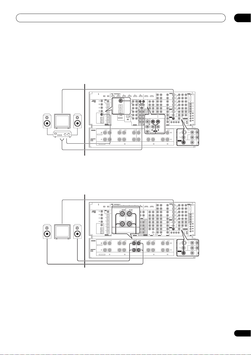
Other connections
C
VCR 1)
C
CENTER
R5 L5
SUR
BAC
(Sin
LOW HIGH
CENTER
07
Basic MULTI-ZONE setup (
1 Connect a separate amplifier to the
OUT
jacks and a TV monitor to the
ZONE 2
)
VIDEO ZONE2 OUT
AUDIO ZONE2
jacks, both on the rear of this amplifier.
You should have a pair of speakers attached to the sub
zone amplifier as shown in the following illustration.
Sub zone
DIGITAL IN
AUDIO IN
MULTI-ZONE setup using speaker terminals (
Main zone
(AUDIO)
COAXIAL
1
IN
ASSIGNABLE
(
)
DVD/LD
1 4
2
IN
(BD)
3
IN
(CD)
4
IN
(SACD)
ZONE2
ZONE2
OUT
OUT
ZONE3
/SOURCE
OUT
SOURCE
OUT
R1
SPEAKERS
Normal
FRONT FRONTCENTER
SELECTABLE
SELECTABLE
R1 R5
L1
L5
SEE
INSTRUCTION
MANUAL
VOIR LE MODE
All ch Bi-Amp.
D'EMPLOI
HDMI
ASSIGNABLE
IN1IN2IN3IN4IN5IN
S400S400
RF IN
2
(
)
For LD
1
IN
(TV)
2
IN
(SAT)
3
IN
(DVR/
VCR 1)
4
IN
(DVR/
VCR 2)
5
IN
(VIDEO/
GAME
1)
6
IN
(CD-R/
TAPE/
MD)
OPTICAL
1 6
ASSIGNABLE
R2
SURROUND-A
LOW HIGH
R
FRONT
ZONE 2
You must select 7.2ch+ZONE 2 in Speaker output setting
on page 43 to use this setup. Note that the sound in the
sub zone will be temporarily interrupted when controlling
the main zone (for example, changing the input source or
starting playback).
Sub zone
Main zone
(AUDIO)
RF IN
COAXIAL
1
IN
2
ASSIGNABLE
(
)
DVD/LD
1 4
(
For LD
IN
2
IN
(TV)
(BD)
IN
3
IN
(SAT)
(CD)
IN
4
IN
(DVR/
(SACD)
VCR 1)
IN
(DVR/
ZONE2
OUT
VCR 2)
IN
(VIDEO/
GAME
ZONE3
/SOURCE
OUT
IN
(CD-R/
SOURCE
TAPE/
OUT
OPTICAL
ASSIGNABLE
R1
SPEAKERS
Normal
FRONT FRONTCENTER
SELECTABLE
SELECTABLE
R1 R5
L1
L5
SEE
INSTRUCTION
LOW HIGH
MANUAL
VOIR LE MODE
All ch Bi-Amp.
D'EMPLOI
HDMI
ASSIGNABLE
IN1IN2IN3IN4IN5IN
S400S400
)
1
2
3
4
5
1)
6
MD)
1 6
R2
SURROUND-A
R
FRONT
2 Connect a separate amplifier to the
ZONE2 OUT
digital output on the rear of this amplifier.
COAXIAL
The amplifier must have an optical digital input to make
this connection. This will allow you to hear the digital
output of a component in a second sub zone.
61
IN
(DVR/
ZONE2
ZONE2
OUT
OUT
VCR 2)
IN
(VIDEO/
GAME
ZONE3
1)
/SOURCE
OUT
IN
(CD-R/
SOURCE
TAPE/
OUT
MD)
IN
LAN (10/100)
iPod
R3 R4 R5 L5
SUR-
SURROUND
ROUND-B
BACK
LOW HIGH
R
SURROUND
OUT1
6
(HDMI CTRL)
OUT2
ZONE2
ZONE2
OUT
OUT
ZONE3
OUT
L
LR
AUDIO
AUDIO
L
FRONT
CENTER
LR
SUR-
ROUND
1
LR
SUR-
ROUND
BACK
MULTI CH
AUDIO
IN
1
L4 L3 L2 L1
SURROUND
BACK
(Single)
HIGH LOW
SURROUND
REC
SEL
OUT
CD-R/
TAPE/
MD
IN
CD
IN
SACD
IN
AUX
IN
IN
PHONO
LR
AUDIO
AUDIO
SURROUND-B
L
12
SUB
WOOFER
L
R
FRONT
12
R
CENTER
LR
R
SUR-
ROUND
(
)
Single
SURROUND
SUB W.
L
BACK
R
R
L
EXTRA
PRE OUT
LOW HIGH
CENTER
S-VIDEO
REC SEL
REC SEL
OUT
OUT
DVR/
VCR 1
IN
IN
REC SEL
REC SEL
OUT
OUT
DVR/
VCR 2
IN
IN
IN
(DVD/LD)
DVD/LD
IN
ASSIGNABLE
BD
IN
MONITOR
OUT
TV
IN
VIDEO
VIDEO
SAT
ZONE2
ZONE2
IN
OUT
OUT
12 V TRIGGER
ZONE2
ZONE2
VIDEO/
OUT
OUT
GAME 1
IN
1 2 34
LR
(
DC OUT 12V TOTAL 250 mA MAX
VIDEOAU DIO
ZONE3
OUT
LLR
LR
SURROUND-A
HIGH LOW
L
FRONT
ASSIGN-
5
1
ABLE
1
IN
(DVD/LD)
2
IN
(BD)
3
IN
(VIDEO/
GAME
1)
4
IN
(DVR/VCR 1)
5
IN
(DVR/VCR 2)
ZONE2
OUT
ZONE3
OUT
RS232C
IN
1
IN
2
IN
3
IN
4
OUT
1
OUT
2
OUT
COMPONENT
VIDEO
3
OUT
CONTROL
4
IN
OUT
)
IR
(DVR/VCR 2)
AC IN
MONITOR
ZONE2
OUT
OUT
VIDEO
VIDEO
ZONE2
ZONE3
ZONE2
OUT
OUT
V
OUT
YP
BPR
)
• Connect a TV monitor to the
VIDEO ZONE2 OUT
jacks on the rear of this amplifier.
Yo u s ho ul d hav e a pa ir of s pe ak er s att ac he d to th e R 5 a nd
L5 terminals as shown below.
YP
BPR
61
SUB
WOOFER
FRONT
CENTER
SUR-
ROUND
SURROUND
BACK
IN
LAN (10/100)
iPod
R3 R4 R5 L5
SUR-
SURROUND
LOW HIGH
SURROUND
CENTER
BACK
R
ROUND-B
R
R
R
EXTRA
PRE OUT
R5 L5
LOW HIGH
LOW HIGH
CENTER
CENTER
6
12
L
12
R
AUDIO
LR
R
(
)
Single
SUB W.
L
L
OUT1
(HDMI CTRL) OUT2
REC
SEL
OUT
ZONE2
OUT
CD-R/
TAPE/
MD
ZONE3
IN
OUT
L
CD
IN
L
SACD
FRONT
IN
TUNER
CENTER
IN
LR
SUR-
IN
ROUND
PHONO
LR
SURROUND
BACK
LR
MULTI CH
AUDIO
IN
L4 L3 L2 L1
SURROUND
SUR-
BACK
ROUND-B
(Single)
HIGH LOW
L
SURROUND
S-VIDEO
REC SEL
REC SEL
OUT
OUT
DVR/
VCR 1
IN
IN
REC SEL
REC SEL
OUT
OUT
DVR/
VCR 2
IN
IN
IN
(DVD/LD)
DVD/LD
IN
ASSIGNABLE
BD
IN
MONITOR
OUT
TV
IN
VIDEO
VIDEO
SAT
ZONE2
ZONE2
IN
OUT
OUT
12 V TRIGGER
VIDEO/
GAME 1
IN
1 2 34
LR
(
DC OUT 12V TOTAL 250 mA MAX
VIDEOAUD IO
SURROUND-A
HIGH LOW
L
FRONT
ASSIGN-
5
1
ABLE
1
IN
(DVD/LD)
2
IN
(BD)
3
IN
(VIDEO/
GAME
1)
4
IN
(DVR/VCR 1)
5
IN
(DVR/VCR 2)
ZONE2
OUT
ZONE3
OUT
RS232C
IN
1
IN
2
IN
3
IN
4
OUT
1
OUT
2
OUT
COMPONENT
VIDEO
3
OUT
CONTROL
4
IN
OUT
)
IR
(DVR/VCR 2)
AC IN
MONITOR
ZONE2
OUT
OUT
VIDEO
VIDEO
ZONE3
ZONE2
ZONE2
OUT
OUT
V
OUT
En
65
Page 66

07
C
VCR 1)
Other connections
Secondary MULTI-ZONE setup (
1 Connect a separate amplifier to the
OUT
jacks and a TV monitor to the
ZONE 3
)
AUDIO ZONE3
VIDEO ZONE3 OUT
jacks, both on the rear of this amplifier.
Sub zone (ZONE 3)
DIGITAL IN
AUDIO IN
Main zone
(AUDIO)
RF IN
COAXIAL
1
IN
2
ASSIGNABLE
(
)
DVD/LD
1 4
(
For LD
IN
2
IN
(TV)
(BD)
IN
3
IN
(SAT)
(CD)
IN
4
IN
(DVR/
(SACD)
VCR 1)
IN
(DVR/
ZONE2
OUT
VCR 2)
IN
(VIDEO/
GAME
ZONE3
ZONE3
/SOURCE
/SOURCE
OUT
OUT
IN
(CD-R/
SOURCE
TAPE/
OUT
MD)
OPTICAL
ASSIGNABLE
R1
4Ω16ΩR26Ω16Ω
SPEAKERS
Normal
FRONT FRONTCENTER
SELECTABLE
SELECTABLE
R1 R5
L1
L5
SEE
INSTRUCTION
LOW HIGH
MANUAL
VOIR LE MODE
All ch Bi-Amp.
D'EMPLOI
HDMI
IN1IN2IN3IN4IN5IN
S400S400
)
1
2
3
4
5
1)
6
1 6
SURROUND-A
R
FRONT
Using the MULTI-ZONE controls
The following steps use the front panel controls to adjust
the sub zone volume and select sources.
ZONE remote controls on page 67.
PARAMETER
or
MCACC
SETUP MIC
ZONE3
AUDIO VIDEO
ENTER
SETUP
RETURN
ACTIVE MONITOR
L5L4L3L2L1
to select the desired zone
ZONE2 ZONE3
ZONE2 ZONE3
CTRL
CTRL
MULTI-ZONE CONTROL
MULTI-ZONE CONTROL
SPEAKERS AUTO SURROUND
INPUT
INPUT
SELECTOR
SELECTOR
STANDBY/ON
1 Press
/STREAM DIRECT
PHONES
ZONE2
(room).
The zone turns on and off each time the corresponding
button is pressed. It is possible to turn both on.
STATUS
LCD
VIEW
R1R2R3R4R5
1
See MULTI-
DIMMER
VIDEO/GAME 2 INPUT
AUDIO
USB
DIGITAL INS-VIDEO VIDEO L R
SC-LX90
MASTER
MASTER
VOLUME
VOLUME
2 Connect a separate amplifier to the
SOURCE OUT
digital output on the rear of this
ZONE3/
amplifier.
The amplifier must have an optical digital input to make
this connection. This will allow you to hear the digital
output of a component in a second sub zone.
61
ASSIGNABLE
IN
(DVR/
ZONE2
OUT
VCR 2)
IN
(VIDEO/
GAME
ZONE3
1)
/SOURCE
OUT
IN
(CD-R/
SOURCE
TAPE/
OUT
MD)
IN
LAN (10/100)
iPod
R3
6Ω16ΩR46Ω16ΩR56Ω16ΩL56Ω16Ω
SUR-
SURROUND
ROUND-B
BACK
LOW HIGH
R
SURROUND
2 Press
OUT1
6
(HDMI CTRL)
OUT2
12
SUB
WOOFER
L
R
FRONT
12
R
CENTER
LR
R
SUR-
ROUND
(
)
Single
SURROUND
SUB W.
L
BACK
R
R
L
EXTRA
PRE OUT
LOW HIGH
CENTER
REC
SEL
OUT
ZONE2
OUT
CD-R/
TAPE/
MD
ZONE3
ZONE3
IN
OUT
OUT
L
LR
CD
AUDIO
AUDIO
IN
L
SACD
FRONT
IN
AUX
CENTER
IN
LR
SUR-
IN
ROUND
1
PHONO
LR
SUR-
ROUND
BACK
LR
MULTI CH
AUDIO
IN
1
L4
6Ω16ΩL36Ω16ΩL26Ω16Ω
AUDIO
AUDIO
SURROUND
SUR-
BACK
ROUND-B
(Single)
HIGH LOW
L
SURROUND
CTRL
to select the sub zone(s) you want.
S-VIDEO
REC SEL
REC SEL
OUT
DVR/
VCR 1
IN
REC SEL
REC SEL
OUT
DVR/
VCR 2
IN
(DVD/LD)
DVD/LD
IN
ASSIGNABLE
BD
IN
TV
IN
SAT
IN
ZONE2
VIDEO/
OUT
GAME 1
IN
LR
VIDEOAU DIO
ZONE3
OUT
L1
4Ω16Ω
LLR
LR
SURROUND-A
HIGH LOW
L
FRONT
OUT
IN
OUT
IN
IN
MONITOR
OUT
VIDEO
VIDEO
ZONE2
OUT
12 V TRIGGER
1 2 34
(
DC OUT 12V TOTAL 250 mA MAX
BPR
ASSIGN-
5
1
ABLE
1
IN
(DVD/LD)
2
IN
(BD)
3
IN
(VIDEO/
GAME
1)
4
IN
(DVR/VCR 1)
5
IN
(DVR/VCR 2)
ZONE2
OUT
ZONE3
ZONE3
OUT
OUT
RS232C
IN
1
IN
2
IN
3
IN
4
OUT
1
OUT
2
OUT
COMPONENT
VIDEO
3
OUT
CONTROL
4
IN
OUT
)
IR
(DVR/VCR 2)
AC IN
MONITOR
ZONE2
OUT
OUT
VIDEO
VIDEO
ZONE2
ZONE3
OUT
V
OUT
YP
If you selected ZONE 2 ON and ZONE 3 ON above, you
can toggle among ZONE 2, ZONE 3 and ZONE 2&3.
• When the amplifier is on,
3
make sure that any
operations for the sub zone are done while ZONE and
your selected sub zone(s) show in the display. If this
is not showing, the front panel controls affect the
main zone only.
3Use the
INPUT SELECTOR
dial to select the source
for the zone you have selected.
For example, ZONE 2 CD-R sends the source connected
to the CD-R inputs to the primary (ZONE 2) sub room.
4Use the
MASTER VOLUME
dial to adjust the
volume.
This is only possible if you selected the VARIABLE
volume control in ZONE Audio Setup on page 97.
5 When you’re finished, press
CTRL
again to return to
the main zone controls.
You can also press the ZONE 2 or ZONE 3 button on the
front panel to switch off all output to the sub zone(s).
2
4
5
66
En
Note
1 When you use ZONE 3, you must set ZONE 3 / RECSEL Setting in the ZONE Audio Setup menu to ZONE 3 (page 97).
2 Note that when recording, this also selects the RECOUT input source. See Making an audio or a video recording on page 102 for more on this.
3 If the amplifier is in standby, the display is dimmed, and ZONE and your selected sub zone(s) continue to show in the display.
4 The volume levels of the main and sub zones are independent.
5 • You won’t be able to switch the main zone off completely unless you’ve switched off the MULTI-ZONE control first.
• If you don’t plan to use the MULTI-ZONE feature for awhile, turn off the power in both the sub and main rooms so that this amplifier is in standby.
Page 67

Other connections
OUT
IN
1
IN
2
IN
3
IN
4
1
OUT
2
OUT
3
OUT
4
IR
CONTROL
COMPONENT
VIDEO
IN
OUT
3
IN
5
07
MULTI-ZONE remote controls
Set the MULTI-ZONE operation switch to ZONE 2 or
ZONE 3 to operate the corresponding zone.
The following table shows the possible MULTI-ZONE
remote controls:
Button What it does
Switches on/off power in the currently selected sub
zone.
INPUT
SELECT
Input
source
buttons
Use to select the input source in the currently
selected sub zone.
Use to select the input source directly (this may not
work for some functions) in the currently selected sub
zone.
VOL +/– Use to set the listening volume in the currently
selected sub zone.
Connecting an IR receiver
If you keep your stereo components in a closed cabinet or
shelving unit, or you wish to use the sub zone remote
control in another zone, you can use an optional IR
receiver (such as a Niles or Xantech unit) to control your
system instead of the remote sensor on the front panel of
this amplifier.
1 Connect the IR receiver sensor to the
the rear of this amplifier.
1
Closete or shelving unit
OUT2
SURROUND
REC
SEL
OUT
CD-R/
TAPE/
MD
IN
CD
IN
SACD
IN
TUNER
IN
IN
PHONO
SUR-
SUR-
ROUND-A
ROUND-B
L
Non-Pioneer
component
Pioneer
component
S-VIDEO
REC SEL
REC SEL
OUT
OUT
DVR/
VCR 1
IN
IN
REC SEL
REC SEL
OUT
OUT
DVR/
VCR 2
IN
IN
IN
(DVD/LD)
DVD/LD
IN
ASSIGNABLE
BD
IN
MONITOR
OUT
TV
IN
VIDEO
SAT
ZONE2
IN
OUT
12 V TRIGGER
VIDEO/
GAME 1
IN
1 2 34
LR
(
DC OUT 12V TOTAL 250 mA MAX
VIDEOAUDIOLRAUDIO
FRONT
HIGH LOW
L
FRONT
ZONE3
OUT
IR
IN
CONTROL
IN OUT
OUT1
(HDMI CTRL)
ZONE2
OUT
ZONE3
OUT
L
DIO
L
FRONT
CENTER
L
SURROUND
L
SURROUND
BACK
MULTI CH
IN
L4 L3 L2 L1
SURROUND
BACK
(Single)
HIGH LOW
IR IN
jack on
IN
YP
BPR
ASSIGN-
1
5
ABLE
1
IN
(DVD/LD)
RS-
2
IN
232C
(BD)
3
IN
(VIDEO/
IN
IN
GAME
1)
1
1
4
IN
IN
(DVR/VCR 1)
2
IN
5
IN
3
(DVR/VCR 2)
IN
4
OUT
OUT
ZONE2
1
1
OUT
OUT
2
OUT
COMPONENT
VIDEO
3
OUT
CONTROL
4
IN
OUT
OUT
)
IR
IR
AC IN
1
OUT
1
OUT
IR
2 Connect the
IR OUT
jack on the rear of this amplifier to link it to the
IR IN
jack of another component to the
IR receiver.
Please see the manual supplied with your IR receiver for
the type of cable necessary for the connection.
• If you want to link a Pioneer component to the IR
receiver, see Operating other Pioneer components
with this unit’s sensor on page 111 to connect to the
CONTROL jacks instead of the IR OUT jack.
Switching components on and off using
the 12 volt trigger
You can connect components in your system (such as a
screen or projector) to this amplifier so that they switch
on or off using 12 volt triggers when you select an input
function. However, you must specify which input
functions switch on the trigger using the The Input Setup
menu on page 94. Note that this will only work with
components that have a standby mode.
12V
TRIGGER
ABLE
MONITOR
OUT
VIDEO
ZONE3
ZONE2
OUT
OUT
12 V TRIGGER
12 V TRIGGER
1 2 34
1234
(
(
DC OUT 12V TOT AL 250 mA MAX
DC OUT 12V TOT AL 250 mA MAX
(DVR/VCR 2)
ZONE2
OUT
VIDEO/
GAME 1
• Connect the
BD
IN
TV
IN
SAT
IN
IN
VIDEO
12 V TRIGGER
the 12 V trigger of another component.
Use a cable with a mono mini-plug on each end for the
connection.
• The trigger maximum power is DC OUT 12 V/50 mA.
After you’ve specified the input functions that will switch
on the trigger, you’ll be able to switch the component on
or off just by pressing the input function(s) you’ve set on
page 94.
2
IN
4
OUT
1
OUT
2
COMPONENT
VIDEO
CONTROL
IN
)
)
OUT
3
OUT
4
OUT
IR
jack of this amplifier to
IR receiver
Note
1 • Remote operation may not be possible if direct light from a strong fluorescent lamp is shining on the IR receiver remote sensor window.
• Note that other manufacturers may not use the IR terminology. Refer to the manual that came with your component to check for IR compatibility.
• If using two remote controls (at the same time), the IR receiver’s remote sensor takes priority over the remote sensor on the front panel.
• Connections using up to four devices and IR receivers can be made with this amplifier.
2 Triggered connections with up to 4 devices compatible with 12-volt triggers can be made with this amplifier.
67
En
Page 68

07
Other connections
Using this amplifier with a Pioneer
plasma television
If you have a Pioneer plasma television, you can use an
SR+ cable
of various convenient features, such as automatic video
input switching of the plasma television when the input
is changed.
1
to connect it to this unit and take advantage
2
CONTROL
OUT
• Use a 3-ringed miniplug SR+ cable to connect the
CONTROL IN
OUT
jack of your plasma television.
jack of this amplifier with the
VIDEO
INPUT 1
Pioneer plasma
television
CONTROL
VIDEO
INPUT 2
Pioneer plasma
television
YP
ZONE3
OUT
IN
(DVD/LD)
IN
(BD)
IN
(VIDEO/
GAME
1)
IN
(DVR/VCR 1)
IN
(DVR/VCR 2)
ZONE2
OUT
BPR
ASSIGN-
1
5
1
2
3
4
5
ABLE
RS232C
IN
1
IN
2
IN
3
IN
4
OUT
1
OUT
2
OUT
COMPONENT
VIDEO
3
OUT
CONTROL
CONTROL
)
4
IN
IN
OUT
IR
S-VIDEO
REC SEL
REC SEL
OUT
OUT
DVR/
VCR 1
IN
IN
REC SEL
REC SEL
OUT
OUT
DVR/
VCR 2
IN
IN
IN
(DVD/LD)
DVD/LD
IN
ASSIGNABLE
BD
IN
MONITOR
OUT
TV
IN
VIDEO
SAT
ZONE2
IN
OUT
12 V TRIGGER
VIDEO/
GAME 1
IN
VIDEOO
1 2 34
(
DC OUT 12V TOTAL 250 mA MAX
L
Important
• You can’t use the SR+ features when HDMI Control
is set to ON. Make sure to set HDMI Control to OFF
when you use the SR+ features (page 92).
• If you connect to a Pioneer plasma television using
an SR+ cable, you will need to point the remote
control at the plasma television remote sensor to
control the amplifier. In this case, you won’t be able
to control the amplifier using the remote control if
you switch the plasma television off.
• Before you can use the extra SR+ features, you need
to make a few settings in the amplifier. See The Input
Setup menu on page 94 and SR+ Setup for Pioneer
plasma televisions on page 97 for detailed
instructions.
DVD player
DVD/LD
AUDIO IN
INPUT
SELECTOR
STANDBY/ON
ACTIVE MONITOR
R1R2R3R4R5
L5L4L3L2L1
Satellite receiver, etc.
SAT
AUDIO IN
SC-LX90
MASTER
VOLUME
This amplifier
To make the most of the SR+ features, you should
connect your source components (DVD player, etc.) in a
slightly different way to that described in this chapter. For
each component, connect the video output directly to the
plasma television, and just connect the audio (analog
and/or digital) to this amplifier.
68
En
Note
1 The 3-ringed SR+ cable from Pioneer is commercially available under the part number ADE7095. Contact the Pioneer Customer Support division for
more information on obtaining an SR+ cable (you can also use a commercially available 3-ringed mini phone plug for the connection).
2 This amplifier is compatible with all SR+ equipped Pioneer plasma televisions from 2003 onward.
Page 69

Other connections
07
Using the SR+ mode with a Pioneer
plasma television
When connected using an SR+ cable, a number of
features become available to make using this amplifier
with your Pioneer plasma television even easier. These
features include:
• On-screen displays when making amplifier settings,
such as speaker setup, MCACC setup, and so on.
• On-screen volume display.
• On-screen display of listening mode.
• Automatic video input switching on the plasma
television.
• Automatic volume muting on the plasma television.
See also SR+ Setup for Pioneer plasma televisions on
page 97 for more on setting up the amplifier.
Important
• The SR+ features do not work when any of the iPod
or HOME MEDIA GALLERY function is selected.
SOURCE
SOURCE
TV AMP
TV AMP
VOLCH
1 Make sure that the plasma television and this
amplifier are switched on and that they are connected
with the SR+ cable.
See Using this amplifier with a Pioneer plasma television
on page 68 for more on connecting these components.
• Make sure you have also selected the display input to
which you’ve connected the amplifier in The Input
Setup menu on page 94.
2 To switch SR+ mode on/off, set the operation
selector switch to
AMP
The front LCD display shows SR+ ON or SR+ OFF.
• The automatic video input switching and the
automatic volume muting features are enabled
separately; see SR+ Setup for Pioneer plasma
televisions on page 97.
SIGNAL SEL SLEEP AUDIODIMMER
SR+
SBch PHASE iPod CTRL
SR+
A.ATT GENRE
VOL
CLR
MCACC
HDMI OUT
DISP
CH
, then press the SR+ button.
Connecting a PC for Advanced MCACC
output
When using the Acoustic Calibration EQ Professional
(see page 47) to calibrate the reverb characteristics of
your listening room, you can graphically check the
results on your computer connected to this amplifier.
Also, when the Full Band Phase Control function is
activated, you can visually check the calibrated
characteristics of group delay of the speakers and the
corrected characteristics of group delay processed by the
exclusive correction filter by installing the corresponding
PC application on your computer.
Use a commercially-available RS-232C cable to connect
the RS-232C jack on your computer to the 9-pin RS-232C
jack on the back panel of this amplifier (the cable must
be cross type, female–female).
The software to output the results is available from the
support area of the Pioneer website
(http://www.pioneer.eu). Instructions for using the
software are also available here. If you have any
questions about the sofrware, please contact the Pioneer
Service Center specified on your warranty card.
Please make sure your system meets the following
requirements:
• Operating system must be Microsoft Windows
®
(Service Pack 2) or Windows
2000.
• CPU must be at least Pentium 3 / 300 MHz or AMD
K6 / 300 MHz (or equivalent) with at least 128 MB of
memory, and your monitor must be able to display a
minimum resolution of 800x600.
• An RS-232C port connector is necessary for graphical
output. Refer to the operating instructions and/or the
PC manufacturer for more information on making
the proper port settings.
• System must have internet access.
• Connect your computer to the RS-232C jack on the
rear panel of the amplifier.
Make sure that the amplifier and all connected
components are switched off and disconnected from the
power outlet when you do this.
1
®
XP
Note
1 Make sure that you do this before continuing to the Reverb Measurement option in Using Acoustic Calibration EQ Professional on page 48 (measurement
data is cleared if you switch off the power).
69
En
Page 70

07
Other connections
Use a commercially-available cable to connect the
RS-232C jack on your computer to the 9-pin RS-232C jack
on this amplifier. See the documentation provided with
the Advanced MCACC application for more information.
RS-232C
Personal computer
Advanced MCACC output using your PC
Before continuing, make sure you have completed step 1
in Data Management on page 50. Note that transmission
data is erased when the amplifier is turned off.
1 Select ‘
When the amplifier is ready for transmission, Start the
MCACC application on your PC shows on the OSD.
2 Start the MCACC application on your computer.
Follow the instructions provided with the application. It
will take about ten seconds for the transmission to
complete, then you will be able to analyze the output on
your computer. Since the data will be cleared from the
amplifier when you restart reverb measurement or turn
off the amplifier, you might want to save the information
on your PC after measurement.
3 When you’re finished, press
You will return to the Data Management menu. Continue
with other settings in the Data Management menu if
necessary. Press RETURN again to exit the Data
Management menu.
Output PC
DVD/LD
5. Data Management
a. MCACC Data Check
b. Memory Rename
c. MCACC Memory Copy
d. MCACC Memory Clear
e. Output PC
’ and press
-
55.0
dB
DVD/LD
5e. Output PC
Start the MCACC
application on your PC.
:Return
ENTER
RETURN
.
:Cancel
.
-
55.0
dB
70
En
Page 71

Playback with HOME MEDIA GALLERY inputs
08
Chapter 8:
Playback with HOME MEDIA GALLERY
inputs
PlaysForSure
PlaysForSure is a marketing certification given by
Microsoft. The PlaysForSure logo makes it easy to find
digital media stores and devices that work together.
Enjoying the Home Media Gallery
With Home Media Gallery, you can enjoy digital content
such as movies, music and photo files. Playable content
is files stored on one or more media servers connected by
a home network (LAN) or those stored on a USB flash
drive. After connecting via a broadband router or an
Ethernet hub to a media server with network software*,
you can navigate through the digital content on the
Home Media Gallery. For USB interface, this amplifier
supports Mass Storage Class devices.
* Referred to as a “media server” that contains digital
content such as movies, music and photo files. PCs
that have pre-installed media server software and
recorders with a media server function are considered
the media server. There are some media servers that
you can choose from; for example, Windows Media
Connect, Windows Media Player that has a media
sharing function, and DLNA compliant servers.
Usable free media servers
Free media servers available from Microsoft include:
1. Windows Media Connect 2.0
Windows Media Connect runs on a 32-bit PC with
Windows XP Service Pack 2 (SP2) installed. When it
is already installed, you can enjoy Home Media
Gallery using your PC.
2. Windows Media Player 11 for Windows XP
Windows Media Player 11 features Media Sharing
that runs on a 32-bit PC with Windows XP Service
Pack 2 (SP2) installed. If Windows Media Connect 2.0
is not installed in your PC, you can download
Windows Media Player 11 from Microsoft’s website.
3. Windows Media Player 11 for Windows Vista
Windows Media Player 11 will be featured in 32-bit
Windows Vista PCs.
When selecting the most suitable media server, please
visit Microsoft’s website for system requirements, known
issues, installation procedures and other updated
information.
Digital media purchased from online stores carrying the
PlaysForSure logo is available for use on this unit.
This unit complies with PlaysForSure Requirements
Specification for Network Devices Version 1.21.
The PlaysForSure logo, Windows Media and the Windows
logo are trademarks or registered trademarks of Microsoft
Corporation in the United States and/or other countries.
DLNA CERTIFIED™ Audio/Video/Image Player
The Digital Living Network Alliance (DLNA) is a crossindustry organization of consumer electronics,
computing industry and mobile device companies.
Digital Living provides consumers with easy sharing of
digital media through a wired or wireless network in the
home.
The DLNA certification logo makes it easy to find
products that comply with the DLNA Interoperability
Guidelines. This unit complies with the DLNA Home
Networked Device Interoperability Guidelines v1.0.
When a PC running DLNA server software or other
DLNA-compatible device is connected to this amplifier,
some setting changes of software or other devices may
be required. Please refer to the operating instructions for
the software or device for more information.
DLNA and DLNA CERTIFIED are trademarks and/or service
marks of Digital Living Network Alliance.
Supported file formats
The table below shows supported file formats that can be
played back or displayed on this amplifier. These formats
are applicable to network sources. Most of them are also
applicable to USB sources. However, media server
content protected by digital rights management, such as
WMDRM10 (Windows Media Digital Rights
Management 10), may not play on this amplifier. For
detailed information about file formats, see Details of
compatible formats on page 89.
71
En
Page 72

08
L
L
L
L
1
1
Playback with HOME MEDIA GALLERY inputs
Type of files Format
Movie MPEG PS (mpg, mpeg, mpe, m2p), MPEG-2 TS,
WMV (asf, wmv), MPEG4 (mp4)
Music MP3 (mp3), LPCM, WAV (wav), WMA (wma),
MPEG-4 AAC (m4a)
Photo JPEG (jpg, jpeg), BMP (bmp), PNG (png), TIFF (tif,
tiff), GIF (gif)
• Some formats may not be supported nor displayed on
Home Media Gallery as formats that individual media
servers support vary. Refer to the manufacturer’s or
other relevant website for supported formats on your
media server.
•Even with the format included in the above table,
some functions may not operate properly depending
on the content.
•Even with the format included in the above table,
some files may not be played properly through a USB
device.
Note
• Content may not play or display properly depending
on the conditions of use.
• Sources for this amplifier include media servers
running on the LAN network, or SD Card, MS, MMC,
xD Picture and CF that comply with the Mass Storage
File System through a USB interface.
• Home Media Gallery complies with DLNA version 1.0
and PlaysForSure version 1.21. If your media server
supports different DLNA and/or PlaysForSure
version(s), some Home Media Gallery function(s) and
content format(s) may not be supported.
• Supported formats and contents are subject to
change. Visit the Pioneer website for updated
information: http://www.pioneer.eu
• The Home Media Gallery functions as a
WMDRM10-ND (Microsoft Windows Media DRM for
networked devices). Content can only be navigated
from the media servers that support WMDRM10-ND.
• The system may not be able to display content from
incompatible memory cards.
• You cannot use the Home Media Gallery until
dimmed elements on the menu screen turn white.
• Some Home Media Gallery functions, such as trick
play during Fast Forward and Rewind, Time Search
and Search, may not work depending on the media
server’s capability and functionality.
Connecting to the network through
LAN interface
Caution
• Before making or changing the connections, switch
off the power and disconnect the power cord from the
power outlet. Plugging in should be the final step.
SC-LX90
(AUDIO)
S400S400
COAXIAL
ASSIGNABLE
1 4
RF IN
1
IN
2
(
)
DVD/LD
(
)
For LD
1
IN
2
IN
(TV)
(BD)
2
IN
3
IN
(SAT)
(CD)
3
IN
4
IN
(DVR/
(SACD)
VCR 1)
4
IN
(DVR/
ZONE2
OUT
VCR 2)
5
IN
(VIDEO/
GAME
ZONE3
1)
/SOURCE
OUT
6
IN
(CD-R/
SOURCE
TAPE/
OUT
MD)
OPTICAL
1 6
ASSIGNABLE
LAN cable
(Sold separately)
Router
LAN
321
PC1
By connecting this amplifier to the network via the LAN
terminal, you can play back files stored on components
on the network, including your PC.
Connect the LAN terminal on this amplifier to the LAN
terminal on your router (with or without the built-in DHCP
server function) with a straight LAN cable (CAT 5 or
higher).
Turn on the DHCP server function of your router. In case
your router does not have the built-in DHCP server
function, it is necessary set up the network manually. For
details, see Network Setup on page 85.
61
HDMI
ASSIGNABLE
IN1IN2IN3IN4IN
SUB
WOOFER
FRONT
CENTER
SURROUND
SURROUND
BACK
R
IN
LAN (10/100)
LAN (10/100)
iPod
EXTRA
WAN
LAN cable
(sold separately)
to LAN port
to LAN port
PC2
1
5
2
R
2
R
(
)
Single
R
PRE OUT
72
En
The specifications of a LAN terminal
LAN terminal . . . . . . . . . . . . . . . . . . . . . . . . . . . . Ethernet jack
Note
1 With Windows Media Connect or Windows Media Player 11, you can even play back copyrighted audio files on this amplifier.
10BASE-T/100BASE-TX
Page 73

Playback with HOME MEDIA GALLERY inputs
08
Using the USB interface
It is possible to play back files1 using the USB interface
on the front of this amplifier.
ZONE2 ZONE3
CTRL
MULTI-ZONE CONTROL
SPEAKERS AUTO SURROUND
/STREAM DIRECT
This amplifier
PHONES
MCACC
SETUP MIC
PARAMETER
AUDIO VIDEO
ENTER
SETUP
RETURN
LCD
STATUS
DIMMER
VIEW
VIDEO/GAME 2 INPUT
USB mass
storage device
USB
USB
AUDIO
DIGITAL INS-VIDEO VIDEO L R
Confirming the IP Address
After making the network connection, follow the
instructions below to confirm the panel’s IP Address
before accessing the network. (The setup is effective for
Auto only. To perform the procedure, DHCP on your
server or router must be valid.)
1Press
The Home Media Gallery screen is displayed.
2 Select ‘
3 Select ‘
4 Select ‘
The screen turns from Select mode to Input mode.
5 Select ‘
The IP Address is automatically assigned.
The Home Media Gallery supports Auto IP and DHCP
(Dynamic Host Configuration Protocol). If the system
failed to acquire the IP Address or if you want to obtain
different addresses, select No then enter IP Address and
Subnet mask. Use the 0 to 9 and /// buttons to
enter an address, then press ENTER. You do not need to
enter Default Gateway and DNS Server.
6 Select ‘OK’ ( then
The Reset dialog appears on screen.
7 Select ‘OK’ and press
The home network module restarts.
A message Setting up Home Media Gallery. Please
wait until initialized. appears on screen.
When the initialization is finished, setting values become
effective and the top menu of the Home Media Gallery
returns.
HOME MEDIA GALLERY
Setup
’ (
/
then
ENTER
Network Setup
’ (
/
Automatically acquire IP
Yes
’ (
/
then
ENTER
ENTER
).
ENTER
.
).
then
’ ( then
).
.
ENTER
).
ENTER
).
Note
• For information on DHCP, refer to network device’s
operating instructions.
• You may need to contact your service provider or
network administrator when manually entering an IP
Address.
• Some media servers block or are programmed to
block access to client servers. When connecting this
amplifier, check the media server for client server
access rights.
Connecting a USB device
You can also enjoy content stored on memory cards by
connecting a USB device to this amplifier. When you
insert a USB flash drive or multi-card reader into the USB
port, the root directory or the Device List screen appears.
In addition, you can connect your digital camera directly
to this amplifier using a USB connector cable.
1Press
The Home Media Gallery screen is displayed.
2Select ‘
The Device List is displayed on screen with the selected
device highlighted if you have not checked in the Single
Server/USB box after selecting Setup and then Auto
Connection Setup. If you have checked in the box, the
list is skipped.
3 Select the desired device (
You can select a device only when the Device List is
displayed.
4Press
content.
To return to the previous screen, press RETURN.
HOME MEDIA GALLERY
USB
’ (
/
then
ENTER
to navigate to a folder or play a file/
ENTER
/
.
).
then
ENTER
).
Note
• If the Home Media Gallery is launched and the Single
Server/USB box is checked after selecting Setup
and then Auto Connection Setup, the system
displays the root directory immediately after inserting
a USB device. In this case, you can start from step 4.
When a multi-card reader is inserted, the Device List
appears with the selected device highlighted. In this
case, you can start from step 3.
Note
1 • Compatible USB devices include external magnetic hard drives, portable flash memory (particularly keydrives) and digital audio players (MP3 players)
of format FAT16/32. It is not possible to connect this unit to a personal computer for USB playback.
• Pioneer cannot guarantee compatibility (operation and/or bus power) with all USB mass storage devices and assumes no responsibility for any loss of
data that may occur when connected to this amplifier.
73
En
Page 74
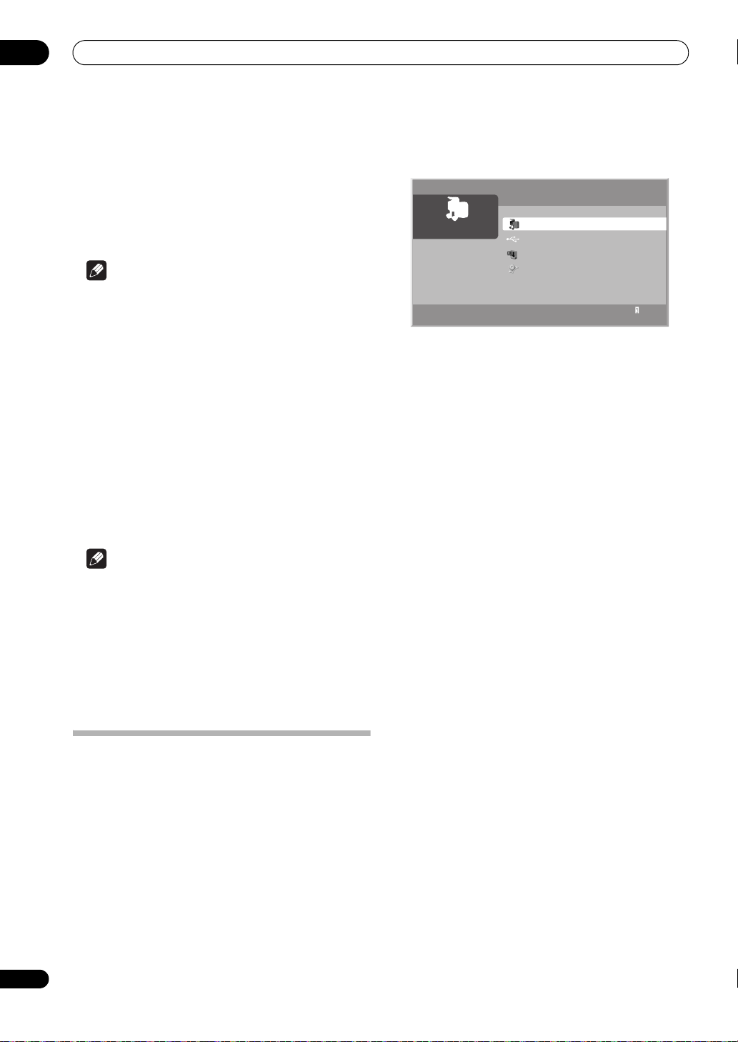
08
Playback with HOME MEDIA GALLERY inputs
Readable USB devices
This system reads FAT16, FAT32 and NTFS.
Readable data files
Movie, music and photo files can also be played with the
exception of Digital Rights Management (WMDRM10)
protected files.
Note
• A single USB device can be connected at a time and
no USB hub connected.
• This system may not be able to display modified or
edited content from a PC or other equipment.
• This system supports the USB Mass Storage Class.
• Some digital cameras may require a setup procedure
for Mass Storage Class data transfer. The setup is
done on the camera. See the operating instructions
supplied with the digital camera.
• This system may not be able to display images,
depending on the type of your memory card, or
camera.
Removing a USB device
To remove a USB device, exit the Home Media Gallery
first and then disconnect the device.
Note
• Be sure to exit the Home Media Gallery screen before
removing the USB device. If you remove the USB
device while the Home Media Gallery screen is
displayed, data inside the memory may be damaged.
• Do not insert or remove the USB device immediately
after this amplifier is switched on or off. This action
may cause data inside the memory to be damaged.
• Pioneer is not liable for any loss or damage to the
data inside the USB flash drive.
• To exit Home Media Gallery, select other input
source.
Home Media Gallery
Server
XXXXXX
Media Navigator
USB
My Playlist
Setup
1
Navigating the files and folders
By selecting Media Navigator, the previously selected
server menu is automatically displayed on the screen by
default (page 85). When only one server is found, the
system automatically connects the server. You can also
use the Tool Menu to switch to another server or
manually select a server from the Server List. The display
is automatically changed to a server list if there are no
previously navigated servers.
1 Press HOME MEDIA GALLERY.
The Home Media Gallery screen is displayed.
2 Select ‘
A server menu appears. The file/folder configuration may
vary depending on the server selected.
After selecting a category, folder or container and
navigating on subsequent screens, you can find a file and
start the appropriate Player depending on the selected
file.
3 Select the desired folder to navigate or file/content
to play (
4 Press
Subsequent screen appears.
To return to the previous screen, press RETURN.
To exit Home Media Gallery, select other input source.
Media Navigator
/
or
/
ENTER
to display a subsequent screen.
then
’ (
/
ENTER
then
).
ENTER
).
74
En
Starting the Home Media Gallery
function
1 Press
The Home Media Gallery screen is displayed.
2 Select ‘
‘
Setup
• To return to the previous screen, press RETURN.
HOME MEDIA GALLERY
Media Navigator
’ (
/
then
ENTER
).
’, ‘
USB
.
’, ‘
My Playlist
’ or
Page 75

Playback with HOME MEDIA GALLERY inputs
08
Selectable screen display
Menu display options are: List, Thumbnail or
Thumbnail List. Press ADV SURR (Yellow) then
select Change view from the Tool Menu to choose
from the screen display options.
List screen
All Photos
XXXX
XXXX
XXXX
XXXX
XXXX
XXXX
XXXX
XXXX
Tool
Thumbnail screen
All Photos
1
Tool
Thumbnail List screen
All Photos
XXXX
XXXX
XXXX
XXXX
Tool
1/27
1
1/27
1
1/27
1
Add to My Playlist
Til
Change view
X
Sort
All
Search
X
Slide Show Settings
Da
2
Detailed Display
Se
Select Searver
X
Stop Music
All Photos
XXXX
List
Thumbnail
Thunbnail List
XXXX
XXXX
XXXX
XXXX
Title
XXXX
Album
XXXX
Date
2006/11/19
Server
XXXXXX
Title
XXXX
Album
XXXX
Date
2006/11/19
Server
XXXXXX
Tool
1/27
Title
XXXX
Album
XXXX
Date
2006/11/19
Server
XXXXXX
Using the Tool Menu
Press ADV SURR (Yellow) on the remote control to
access the pop-up Tool Menu. Various play and display
modes can be selected from the Tool Menu. The
selectable menu items differ depending on the submenu
(see the table below).
Menu items Function Screen on which Tool
Update to
Latest
Updates the server
connection status
Information
Delete Server Deletes the server
that are dimmed on
the list
USB Devices
List
Consecutive
Playback
Moves to the USB
Devices List screen
Continuously plays
a
video content starting
from the selected
item
Detailed
Display
Displays the detailed
a
information on the
selected content
Sort Sorts items in Folder
or Contents List
Search Searches the desired
items in Folder or
Contents List by word
Menu is available
Server List (connected/not
connected)
Server List (server not
connected)
Folder Contents List (USB)/
Contents List (USB)
Folder Contents List/
Contents List
Folder Contents List/
Contents List
Folder Contents List/
Contents List
Media Navigator/Folder
Contents List/Contents List
Menu items Function Screen on which Tool
Menu is available
Slide Show
Setup
Used to set up a slideshow on the Photo
Player
Server List/Media
Navigator/USB/My Playlist/
Playlist List (Movie/Music/
Photo)/Folder Contents
List/Contents List/Photo
Player
a
Adds the selected
files to My Playlist
Add to My
Playlist
Select Server Moves to the Server
List screen
b
Stop Music
Stops playback of a
music file
Folder Contents List/
Contents List/Movie Player/
Music Player/Photo Player
Media Navigator/Folder
Contents List/Contents List
Server List/Media
Navigator/ Playlist List
(Movie/ Music/Photo)/
Folder Contents List/
Contents List/Music
Player/Photo Player
Change Name Used to change
content names in My
Playlist List (Movie/Music/
Photo)
Playlist
Change view Switches the screen
display to List,
Folder Contents List/
Contents List
Thumbnail, or
Thumbnail List
Time Search Starts playback at the
Movie Player/Music Player
preset time on the
Movie or Music Player
screen
Slow Playback Plays back in the slow
Movie Player
mode on the Movie or
Music screen
BGM Setup Used to set up the
Photo Player
slideshow BGM on
the Photo Player
Move Moves the order of
Contents List (Playlist)
content in My Playlist
Delete from
My Playlist
a.When a file is selected
b.While music is played
Deletes the selected
a
content from My
Playlist
Contents List (Playlist)
75
En
Page 76

08
Playback with HOME MEDIA GALLERY inputs
Media Navigator
While navigating through the folders a media server
provides, you can select the desired file to start the
corresponding player by pressing ENTER.
Screen Components
1
Title
Movie
Server
XXXXXX
2
1 Thumbnail of the file selected (if obtained)
2 Name of the server currently selected
3 Current menu level
4 Item being selected (highlighted in yellow)
5 File number/total number of files
6 Number of servers connected
7 Key guide
Note
• The Media Navigator is not launched depending on
the option selected in Auto Connection Setup on
page 85. The screen displays after selecting a server
in the server list.
3
Media Navigator
Movie
Music
Photos
User Files
Tool
7
4
1/4
5
1
6
USB
Like navigating through the media servers, you can select
the desired file contained in the device selected on the
USB Devices List screen to start the corresponding
player by pressing ENTER. You can also select the menu
displayed on either List, Thumbnail or Thumbnail List
screen. Press ADV SURR (Yellow) and select Change
view from the Tool Menu.
My Playlist
Each category (Movie, Music and Photo) has five
different Playlists in which you can register up to 100 files
each. The My Playlist option can contain sound and
image files selected in the Media Navigator. To edit a
Playlist, use the Tool Menu (page 75).
1 Press
HOME MEDIA GALLERY
.
The Home Media Gallery screen is displayed.
2 Select ‘
3 Select a Playlist list from ‘
Playlist
4 Select the desired content (
ENTER
My Playlist
’ or ‘
Photo Playlist
).
’ (
/
’ (
then
ENTER
Movie Playlist
/
then
ENTER
/
or
).
/
’, ‘
Music
).
then
The menu can be displayed as a List, Thumbnail or
Thumbnail List screen. Press ADV SURR (Yellow) then
select Change view from the Tool Menu (/ then
ENTER).
5 Press
ENTER
to play or display.
To return to the previous screen, press RETURN.
To exit Home Media Gallery, select other input source.
Enjoying movie files
You can display the menu as a List, Thumbnail or
Thumbnail List screen. Press ADV SURR (Yellow) then
select an option under Change view on the Tool Menu.
You can also navigate through the subsequent or
preceding menu levels in the server or USB device by
pressing /// or ENTER. When you select movie
content from the server menu on the Media Navigator
screen, the Movie Player automatically launches. Select
a category, folder, or device to access the submenu
containing the required file or content.
The Movie Player screen appears when you select a
movie file from My Playlist, just like selecting a file in the
server.
76
En
Note
• The USB Devices List screen may not be displayed
depending on the option selected in Auto
Connection Setup. Single Server/USB is selected
for Auto Connection Setup by default. You don’t
need to select a device in the USB Devices List when
you use a single directory device (USB flash drive).
Page 77

Playback with HOME MEDIA GALLERY inputs
08
Screen Components
2
13
XXXX
Playback
00 : 00 : 45
ToolRandomRepeatA-B
8
1 Movie icon
2 Title (File name, etc.)
3 Date
4 Album name
5 Play time
6 Play status
7 Key guide
8 Progress bar
9 Audio mode icon
10 A-B repeat mode icon
11 Repeat mode icon
12 Random mode icon (appears when the mode is valid)
XXXX
2006/11/30 00:00:59
L R A-B
9 117 6
4
5
10
RDM
12
Movie Player key guide
Button(s) Function
ENTER Pauses while playback or plays back while in
Fast reverse during playback or when in PAUSE.
Fast forward while playback or PAUSE. Each press
Skips 15 seconds backward and plays back or
Skips 15 seconds forward and plays back or pauses
Plays back the content
Pauses the playback
Stops the Player and returns to the pr evious screen
Same as (only fast forward function while in the
PAUSE
Each press toggles the reverse speed among x 2,
x 4, x 8, x 20, x 50, and x 100 or the slow mode speed
among x 1/2, x 1/4, x 1/8, and x 1/16. When the
beginning of the content is reached, it pauses.
toggles the forward speed among x 2, x 4, x 8, x 20,
x 50, and x 100 or the slow mode speed among
x 1/16, x 1/8, x 1/4, and x 1/2. When the end of the
content is reached, it pauses.
pauses while in PAUSE
while in PAUSE
(List/Thumbnail/Thumbnail List)
slow mode)
Button(s) Function
Same as (only fast reverse function while in the
AUTO/DIRECT
(Blue)
STEREO/
F.S.SURR (Red)
STANDARD
(Green)
ADV SURR
(Yellow)
DISP Displays the Player status at the bottom of the
AUDIO Every press of the key toggles the audio mode
RETURN Same function as
VOL+, VOL– Adjusts the sound volume
MUTE Mutes the sound
Play modes
Time Search (Tool Menu) Plays back the selected content from
Slow
Playback
Add to My
Playlist
Stop Movie
Player
Fast
Forward/
Fast Reverse
Forward/
Reverse
(15 sec.)
Play ENTER, See the key guide table
A-B Repeat
Mode
Repeat
Mode
Random
Mode
(Tool Menu) ADV SURR
slow mode)
Sets A-B repeat mode. Sets the desired point A to
start and B to end during playback. To cancel the
mode, press AUTO/DIRECT (Blue) on the remote
control.
Every press toggles the repeat mode among No
Repeat and Repeat Once or among No Repeat,
Repeat Once and Repeat All while in Playlist
Available only in Playlist or Consecutive Playback
mode. Every press toggles the random mode
between Random Off and Random On.
Switches the Tool Menu display on and off. Even if
the Tool Menu is displayed while content is played
back, a movie is kept playing but the time counter
and progress bar do not function.
screen while a movie is played back. Another press
of the key displays a key guide, as well. Pressing the
key once more cancels all the information display.
among L + R, L and R
the time preset on the Movie Player
(Tool Menu) Plays back the content in slow mode on
(Tool Menu) Adds the selected content to My Playlist
, RETURN Stops the Movie Player
/,
/
/ See the key guide table
AUTO/
DIRECT
(Blue)
STEREO/
F.S.SURR
(Red)
STANDARD
(Green)
(Yellow)
the Movie Player
List
See the key guide table
See the key guide table
See the key guide table
See the key guide table
See the key guide table
77
En
Page 78

08
Playback with HOME MEDIA GALLERY inputs
Note
• Some functions may not be supported depending on
the server type or version used.
• During playback, an error may arise in time-related
information depending on the content or server
software.
• Some functions may not be supported depending on
the content.
Time Search
1 In playback mode or PAUSE, press
(Yellow),
(
/
then select ‘
then
ENTER
Time Search
).
A Time Search dialog screen appears.
2 Select ‘
/
then
Hour
ENTER
’ and/or ‘
).
Minute
Enter the desired time using buttons 0 to 9.
Time Search
Input Time
H
1
OK Cancel
3 Press
4 Select ‘
ENTER
after the entry is complete.
OK
’ ( then
ENTER
The movie begins playing from the time you set.
To cancel the Time Search, select ‘Cancel’ and press
ENTER.
Note
• This function may not be supported depending on the
content or server software.
• An error may arise in time-related information
depending on the content or server software.
•Only Cancel can be selected when you have entered
a time exceeding the content’s time range.
ADV SURR
’ from the Tool Menu
’ for ‘
Input Time
Min
).
’ (
Slow Playback
1 In playback mode or PAUSE, press
(Yellow)
Menu (
2 Press
then select ‘
/
then
ENTER
Slow Playback
ENTER
.
).
Slow playback begins. You can change the playback
speed by pressing / while in the slow mode.
To discontinue slow playback, press ENTER or . The
system returns to the normal playback mode.
ADV SURR
’ from the Tool
Note
• This function may not be supported depending on the
content.
Add to My Playlist
1 While navigating or playing, select the file to be
added to My Playlist (
2 Press
Playlist
ADV SURR (Yellow)
’ from the Tool Menu (
///
then select ‘
/
then
then
A Playlist Selection dialog screen appears.
3 Select a Playlist (
/
then
ENTER
).
A check mark is provided beside the selected Playlist.
When you select a different Playlist and press ENTER, the
mark jumps to the new Playlist from the previously
/
selected one.
Playlist Selection
Select a Playlist to register
Playlist1 20
Playlist2 0
Playlist3 0
Playlist4 0
Playlist5 0
OK Cancel
4 Select ‘OK’ ( then
ENTER
).
The file is added to the selected Playlist.
To cancel the operation, select ‘Cancel’ then press
ENTER.
Fast Forward/Fast Reverse
• While playing content, press and hold for Fast
Reverse or press and hold
for Fast Forward.
Forward/Reverse (15 sec.)
• While playing content, press and hold or to
jump backward or forward in 15-second increments.
A-B Repeat Mode
1 While playing content, press
where you want repeat to start.
2 Press
AUTO/DIRECT
(Blue) again where you want
repeat to end.
The Player status appears on the screen and the A-B
mode icon changes.
The selected movie scenes are repeatedly played back.
To return to normal mode, press AUTO/DIRECT (Blue)
again while in the A-B repeat mode.
AUTO/DIRECT
ENTER
Add to My
ENTER
).
).
(Blue)
78
En
Page 79

Playback with HOME MEDIA GALLERY inputs
08
Note
• The A-B repeat function is only available during
playback in normal mode.
• If the screen display doesn’t match the player status,
a malfunction may have occurred. Stop playback,
then try the operation again.
Repeat Mode
1 While playing content in the Media Navigator or
USB device, press
‘
Repeat Once
STEREO/F.S.SURR (Red)
’.
to select
The title being played is repeated.
2Press
repeat mode (‘
STEREO/F.S.SURR (Red)
Repeat Off
’ is selected).
again to cancel the
After playing the currently selected title, the Player stops.
Note
• When playing content in the Playlist, you can select
from Repeat Off, Repeat All (plays all items in the
Playlist repeatedly) or Repeat Once (plays the
content being watched repeatedly).
Random Mode
1 While playing content in the Playlist, press
STANDARD (Green)
to select ‘
Random On
’.
Random Repeat playback starts.
2Press
random mode (‘
STANDARD (Green)
Random Off
again to cancel the
’ is selected).
Note
• The Random Repeat mode is only available for
content in the Playlist, or in Consecutive Playback
mode.
Enjoying music files
You can display the menu as a List, Thumbnail or
Thumbnail List screen. Press ADV SURR (Yellow)
then select an option under Change view on the Tool
Menu. You can also navigate through the subsequent
or preceding menu levels in the server or USB device
by pressing /// or ENTER.
When you select music content from the server menu
on the Media Navigator screen, the Music Player
automatically launches. Select a category, folder, or
device to access the submenu containing the
required file or content. The Music Player screen
appears when you select a music file from My Playlist,
just like selecting a file in the server.
Note
• The Music Player only displays a List screen.
Screen Components
13
All Music
2
XXXX
XXXX
6
XXXX
00:01:00
Other
Playback
00 : 00 : 14
XXXX
XXXX
XXXX
XXXX
XXXX
XXXX
XXXX
XXXX
8 11 129 7
1 Category or Folder name
2 Jacket image (Music icon)
3 Playing Music icon
4 Contents list
5 Number of items
6 Detailed display
7 Play status
8 Time counter
9 Key guide
10 Progress bar
11 A-B repeat mode icon
12 Repeat mode icon
13 Random mode icon
4
2/20
RDM
ToolRandomRepeatA-B
A-B
10
Music Player key guide
Button(s) Function
Moves up a cursor to a title above
Moves down a cursor to a title below
ENTER Plays back the selected music content. Pauses the
Fast reverse during playback or when in PAUSE.
Fast forward during playback or when in PAUSE.
RETURN Returns to the previous screen (List/Thumbnail/
music content being played if it is highlighted in
the Playlist screen or plays the selected music
content if different content is highlighted by
pressing /.
Each press toggles the reverse speed among x 2,
x 4, x 8, x 20, x 50, and x 100. When the beginning
of the content is reached, it pauses.
Each press toggles the forward speed among x 2,
x 4, x 8, x 20, x 50, and x 100. When the end of the
content is reached, it pauses.
Thumbnail List). Content being played does not
stop.
5
13
79
En
Page 80

08
Playback with HOME MEDIA GALLERY inputs
Button(s) Function
Plays back the selected content. Pauses while in
Pauses the playback
Stops the Player and does not return to the
Same as .
Same as .
AUTO/DIRECT
(Blue)
STEREO/
F.S.SURR (Red)
STANDARD
(Green)
ADV SURR
(Yellow)
VOL+, VOL– Adjusts the sound volume
MUTE Mutes the sound
playback and plays while in PAUSE.
previous screen (Selecting the Stop Music from
the Tool Menu also stops the Player.)
Sets A-B repeat mode. Sets the desired point A to
start and B to end during playback. To cancel the
mode, press AUTO/DIRECT (Blue) on the remote
control.
Every press toggles the repeat mode among No
Repeat, Repeat Once and Repeat All
Every press toggles the random mode among
Random Off and Random On
Displays the Tool Menu. Even if the Tool Menu is
displayed while content is played back, music is
kept playing but the time counter and progress bar
do not function.
Note
• Files may not be played back properly depending on
the content.
Play modes
Add to My
Playlist
Time Search (Tool Menu) Plays back the selected content from
Stop Music (Tool Menu), Stops the Music Player
Fast
Forward/
Fast Reverse
Moves Up/
Down
a cursor
Play ENTER, See the key guide table
A-B Repeat
Mode
Repeat
Mode
Random
Mode
(Tool Menu) ADV SURR
(Tool Menu) Adds the selected content to My Playlist
/,
/
/ See the key guide table
AUTO/
DIRECT
(Blue)
STEREO/
F.S.SURR
(Red)
STANDARD
(Green)
(Yellow)
List
the time preset on the Music Player
See the key guide table
See the key guide table
See the key guide table
See the key guide table
See the key guide table
• Refer to page 75 for the color button ADV SURR
(Yellow) (Tool Menu).
Note
• Some functions may not be supported depending on
the server type or version used.
• Playback continues even when you move from the
Player screen to the previously selected screen by
pressing RETURN.
A-B Repeat Mode
1 While playing content, press
where you want repeat to start.
2 Press
AUTO/DIRECT (Blue)
repeat to end.
The Player status appears on the screen and the A-B
repeat mode icon changes.
The selected part of the title is repeatedly played back.
To return to normal mode, press AUTO/DIRECT (Blue)
again while in the A-B repeat mode.
Note
• The A-B repeat function is only available during
playback in normal mode.
AUTO/DIRECT (Blue)
again where you want
Repeat Mode
1 While playing content in the Media Navigator, USB
device or Playlist, press
select ‘
Repeat All
STEREO/F.S.SURR
’.
(Red) to
All titles in the folder or Playlist are played repeatedly.
2 Press
repeat mode (‘
STEREO/F.S.SURR
Repeat Once
(Red) again to cancel the
’ is selected).
The title being played is repeated.
3 Press
the repeat mode (‘
STEREO/F.S.SURR
Repeat Off
(Red) once more to cancel
’ is selected).
After playing the currently selected title, the Player stops.
Random Mode
1 While playing content in the Playlist, press
STANDARD (Green)
Random Repeat playback starts.
2 Press
STANDARD (Green)
random mode (‘
to select ‘
Random Off
Random On
’.
again to cancel the
’ is selected).
80
En
• Setup procedures for the above play modes are the
same as for the Movie Player.
Page 81

Playback with HOME MEDIA GALLERY inputs
Photo Player key guide
Enjoying photo files
You can display the menu as a List, Thumbnail or
Thumbnail List screen. Press ADV SURR (Yellow) then
select an option under Change view on the Tool Menu.
You can also navigate through the subsequent or
preceding menu levels in the server or USB device by
pressing /// or ENTER.
When you select photo content from the server menu on
the Media Navigator screen, the Photo Player
automatically launches. The selected content is
displayed in full screen by pressing ENTER. Select a
category, folder or device to access the submenu
containing the required file or content.
Pressing ENTER again allows a slideshow to begin. After
a slideshow launches, pressing ENTER toggles between
PLAY and PAUSE. Instead of pressing ENTER twice, you
can press to start the slideshow immediately.
The Photo Player screen appears when you select a photo
file from My Playlist, just like selecting a file in the server.
Screen Components
2
13
XXXX
Playback
6 / 27
7 56
ToolRandomRepeat
8
1 Photo icon
2 File name
3 Folder name, etc.
4 Date
5 Number of items*
6 Play status*
7 Key guide
8 Progress bar*
9 Repeat mode icon
10 Random mode icon
* Displays only when playing the slideshow.
XXXX
2006/11/30
RDM
10
Button(s) Function
ENTER Starts displaying a photo or playing a slideshow.
RETURN Stops the Player and returns to the previous screen
, Displays the previous image content
, Display the next image content
Plays a slideshow
Pauses the slideshow
Stops the Player and returns to the previous screen
Rotates the image 90º clockwise. Each press
Rotates the image 90º counter-clockwise. Each
AUTO/DIRECT
(Blue)
STEREO/
F.S.SURR (Red)
STANDARD
4
(Green)
ADV SURR
(Yellow)
DISP Displays the Player status at the bottom of the
9
VOL+, VOL– Adjusts the sound volume
MUTE Mutes the sound
Play modes
BGM Setup (Tool Menu) Sets up BGM
Slide Show
Setup
Add to My
Playlist
Stop Photo
Player
Move File
Forward/
Backward
Slideshow ENTER, See the key guide table
08
Pauses while playback or plays back while in
PAUSE.
(List/Thumbnail/Thumbnail List)
(List/Thumbnail/Thumbnail List)
toggles the rotation angle by 90º among 90º, 180º,
270º and 0º.
press toggles the rotation angle by 90º among
270º, 180º, 90º, and 0º.
Rotates the image 90º clockwise. Each press
toggles the rotation angle by 90º among 90º, 180º,
270º and 0º.
Available only when playing the slideshow. Every
press toggles the repeat mode between No Repeat
and Repeat All
Available only when playing the slideshow. Every
press toggles the random mode between Random
Off and Random On
Displays the Tool Menu. If the Tool Menu is
displayed while a slideshow is played, the
slideshow and BGM are paused.
screen while image content is played. Another
press of the key displays a key guide, as well. No
Player information is displayed when an image is
shown in full screen (no slideshow has been
started). Other information may display. Pressing
the key once more cancels all the information
display.
(Tool Menu) Allows various slideshow setups on the
Photo player
(Tool Menu) Adds the selected content to My Playlist
List
, RETURN Stops the Photo Player
(///)See the key guide table
81
En
Page 82

08
Playback with HOME MEDIA GALLERY inputs
Play modes
Rotate AUTO/
Repeat
Mode
Random
Mode
(Tool Menu) ADV SURR
DIRECT
(Blue),
/
STEREO/
F.S.SURR
(Red)
STANDARD
(Green)
(Yellow)
See the key guide table
See the key guide table
See the key guide table
See the key guide table
• Setup procedures for the above play modes are the
same as for the Movie Player.
• Refer to page 75 for the color button ADV SURR
(Yellow) (Tool Menu).
Note
• Some functions may not be supported depending on
the server type or version used.
• In rare cases, the image on the screen may appear
jagged when photo content is selected directly from
a USB device. If this is the case, the problem may be
solved by viewing the photo content through the
network after having transferred it to the server PC.
• Even with the supported format, files may not be
played properly depending on the content.
7 Select ‘OK’ ( then
ENTER
).
The slideshow setup finishes.
Note
• After setting the Interval time, it may take longer
than the preset time as the Interval time means the
time up until the Home Media Gallery starts
obtaining the next image. Key operations may not
work while obtaining the next image.
Setting up BGM for the slideshow
1 Press
The Home Media Gallery screen is displayed.
2 Select photo content in the Media Navigator, USB
device or My Playlist (
The Photo Player launches and photo content is
displayed in full screen.
3 Press
from the Tool Menu (
A BGM Setup dialog screen appears.
4 Select a Playlist from the list as BGM (
ENTER
A check mark is provided beside the selected Playlist.
When you select a different Playlist and press ENTER, the
mark jumps to the new Playlist from the previously
selected one.
HOME MEDIA GALLERY
///
ADV SURR
(Yellow) then select ‘
/
then
).
.
then
ENTER
ENTER
BGM Setup
).
/
).
then
’
82
En
Setting up the slideshow
You can enjoy a slideshow with music in the background.
To activate this feature, you must register music content
in My Playlist Lis t bef oreh and ( see My Playlist on page 76
and Setting up BGM for the slideshow below).
1 Press
The Home Media Gallery screen is displayed.
2 Select ‘
3 Press
A pop-up screen of the Tool Menu appears.
4 Select ‘
5 Select the desired setup item (
6 Enter the setting in the ‘
Repeat steps 5 and 6 to enter another setup.
HOME MEDIA GALLERY
Media Navigator
ADV SURR (Yellow)
Slide Show Setup
then
ENTER
).
Effect
Interval 3 seconds
.
’ (
/
then
.
’ (
/
then
/
Effect
’ or ‘
Slide Show Setup
Auto
OK Cancel
ENTER
ENTER
then
Interval
).
).
ENTER
’ box (
).
/
BGM Setup
Playlist1 20
Playlist2 0
Playlist3 0
Playlist4 0
Playlist5 0
BGM ON
OK Cancel
5 Select ‘
OFF
6 Select ‘
BGM ON
’, ‘
BGM ON (Random)
’ from the BGM status box (
OK
’ ( then
ENTER
/
).
then
’ or ‘
ENTER
Note
• When a slideshow is started while a music file is
playing, playback of the music file continues.
BGM
).
Page 83

Playback with HOME MEDIA GALLERY inputs
08
Starting the slideshow
1Press
The Home Media Gallery screen is displayed.
2 Select a folder containing photo content (
ENTER
The Thumbnail screen is displayed (Thumbnail List or List
screen is displayed depending on the setting).
3 Select the desired photo file from the Thumbnail
screen (
The photo content is displayed in full screen.
You can start a slideshow by pressing on the
Thumbnail screen.
4Press
The slideshow starts and photo images in the folder
automatically display one by one. See Setting up the
slideshow on page 82 for setting up the interval time.
To display a key guide, press DISP.
To display the next image content manually, press or
.
To display the previous image content manually, press
or .
5Press
The Photo Player goes into PAUSE.
6Press
To cancel the slideshow and stop the Photo Player, press
RETURN or during the playback. The previous screen
returns.
HOME MEDIA GALLERY
.
/
then
).
///
Title
XXXX
Album
XXXX
Date
2006/11/19
Server
XXXXXX
ENTER
ENTER
ENTER
then
ENTER
).
All Photos
Tool
1/27
or to start a slideshow.
or to stop the slideshow.
again to resume the slideshow.
1
Note
• When you press ///, / while photo
content is displayed, the Photo Player goes into
PAUSE.
Rotating the image
1Press
The Home Media Gallery screen is displayed.
2 Select photo content in the Media Navigator, USB
device or My Playlist (
The photo content is displayed in full screen. To stop the
slideshow, press ENTER again.
HOME MEDIA GALLERY
///
.
then
ENTER
).
3Press
ENTER
or to start a slideshow.
The slideshow starts and photo images in the folder
automatically display one by one.
To display a key guide, press DISP.
4 While using Photo Player, press
(Blue)
to rotate a photo.
AUTO/DIRECT
The displayed image rotates by one quarter clockwise.
Each time AUTO/DIRECT (Blue) is pressed, the image
rotates; 90º, 180º, 270º and Rotate Off.
The Photo Player goes into PAUSE (the slideshow is in
Stop mode).
5Press
ENTER
again to resume the slideshow.
The selected rotation mode is only effective for the image
being displayed. The default setting (Rotate Off) returns
when you move and display content on a different screen.
Repeating the slideshow
1 While playing a slideshow, press
(Red)
to select ‘
Repeat All
’.
The slideshow being played is repeated.
2Press
repeat mode (‘
STEREO/F.S.SURR (Red)
Repeat Off
’ is selected).
After playing the currently selected slideshow, the Player
stops.
STEREO/F.S.SURR
again to cancel the
Playing the slideshow at random
1 While playing a slideshow, press
(Green)
to select ‘
Random On
Random playback starts.
2Press
random mode (‘
STANDARD (Green)
Random Off
’ is selected).
STANDARD
’.
again to cancel the
Other useful functions
Search
You can search the desired items contained in the Folder
or Contents List by word. Searched results are displayed
on the screen.
1Press
The Home Media Gallery screen is displayed.
2 Select the desired folder and/or content in the
Media Navigator (
3Press
the Tool Menu (
A Search dialog screen appears.
HOME MEDIA GALLERY
///
ADV SURR (Yellow)
/
then
then
then select ‘
ENTER
.
ENTER
).
).
Search
’ from
83
En
Page 84

08
Playback with HOME MEDIA GALLERY inputs
4 Select the ‘
search condition:
Contains the following
’ ( then
ENTER
).
’ box in ‘
Set the
The software keyboard appears on the screen.
XXXX
Title
XXXX
Album
XXXX
Date
2006/11/30
Play Time
00:00:59
Server
XXXXXX
Search
Set the search condition.
Title
Contains the following:
OK Cancel
Tool
1/24
1
5 Enter the word for search on the software
keyboard (
6 Select ‘
ENTER
///
OK
’ on the software keyboard (
then
).
ENTER
).
/
then
The software keyboard disappears.
To cancel the search, select ‘Cancel’ then press ENTER.
7 Select ‘OK’ on the ‘
ENTER
).
Search
’ dialog screen ( then
The searching starts based on the word entered and
search results are displayed.
Even while searching, you can select content to play. To
return to the search screen, press RETURN during
playback.
8 Press
RETURN
to cancel the search mode.
Note
• Search may not be available depending on the server
used.
Sort
You can sort the items contained in the Folder or
Contents List.
1 Press
The Home Media Gallery screen is displayed.
2 Select the desired folder and/or content in the
Media Navigator (
3 Press
the Tool Menu (
A Sort dialog screen appears.
HOME MEDIA GALLERY
///
ADV SURR (Yellow)
/
then
then
then select ‘
ENTER
.
ENTER
).
).
Sort
’ from
4 Select ‘
Order
5 Select ‘
ENTER
Bottom-Up
’ box ( then
Title
XXXX
Album
XXXX
Date
2006/11/30
Play Time
00:00:59
Server
XXXXXX
OK
’ on the ‘
).
’ or ‘
ENTER
XXXX
Select a sorting order.
Sort Order
Bottom-Up
OK Cancel
Sort
Top-Down
’ in the ‘
Sort
).
Sort
Title
Tool
1/24
1
’ dialog screen ( then
The sorting starts based on your selection and sort
results are displayed.
Even while sorting, you can select content to play. To
return to the sort screen, press RETURN during playback.
6 Press
RETURN
to cancel the sort mode.
Note
•The Select a sorting order. screen can be displayed
while navigating through the music categories.
Adding files to My Playlist
The Home Media Gallery function provides My Playlist a self-contained play list that allows you to bookmark your
favorite movie, music and photo files from the network.
You can register, edit, and sort up to 100 files in each
Playlist List.
1 Press
The Home Media Gallery screen is displayed.
2 Select ‘
3 Select the desired music content to add to ‘
Playlist
4 Press
Playlist
A dialog screen appears.
HOME MEDIA GALLERY
Media Navigator
’ (
/
then
ENTER
).
ADV SURR
(Yellow), then select ‘
’ from the Tool Menu (
Playlist Selection
Select a Playlist to register
Playlist1 20
Playlist2 0
Playlist3 0
Playlist4 0
Playlist5 0
OK Cancel
’ (
/
/
.
then
then
ENTER
).
My
Add to My
ENTER
).
84
En
5 Select the Playlist to which you want to add the
contents (
/
then
ENTER
).
A check mark is provided in the box at the selected
Playlist List.
Page 85

Playback with HOME MEDIA GALLERY inputs
08
6 Select ‘OK’ on the ‘
Playlist Selection
’ dialog screen.
The selected content is added to the Playlist.
Note
• When giving a slideshow of photo content, you can
use Music Playlist as for background music.
Setup
The Setup is used for Network Setup, Auto
Connection Setup, Default Settings, Software
Update and Home Media Gallery Version.
Setup
Network Setup
Auto Connection Setup
Default Settings
Software Update
Home Media Gallery Version
1/5
1
1Press
The Home Media Gallery screen is displayed.
2 Select ‘
3 Select ‘
‘
Default Settings
Media Gallery Version
Network Setup
When you select Network Setup from the Setup menu,
a submenu is displayed to select Auto or Manual for
network connections.
To automatically set:
The following setup is effective for Auto only. To perform
the procedure, DHCP on your server or router must be
valid.
1 Select ‘
(
2 Select ‘
3 Select ‘
A restart dialog screen appears.
4Press
The setup finishes.
The system restarts then the Home Media Gallery screen
returns.
To manually set:
Before setting up, check your media server for IP Address
and Subnet mask.
HOME MEDIA GALLERY
Setup
’ (
/
Network Setup
’, ‘
Automatically acquire IP
then
ENTER
).
Yes
’ (
/
OK
’ ( then
ENTER
again on the dialog screen.
.
then
ENTER
’, ‘
Auto Connection Setup
Software Update
’ (
/
then
then
ENTER
).
ENTER
).
).
’ and ‘
Home
ENTER
).
’ then press
ENTER
1Select ‘
(
then
2Select ‘
3 Select the setup item’s box (
ENTER
Automatically acquire IP
ENTER
).
No
’ (
/
then
).
ENTER
’ then press
).
///
The screen turns to entry mode for IP Address and
Subnet mask.
No need to enter Default Gateway and DNS Server.
4 Enter the figures using buttons 0 to 9.
Subnet mask (such as 255.255.255.0)
Enter the same figures as you checked.
IP Address (such as 192.168.201.***)
Enter the same figures as used in the media server (PC,
etc.) you use. For ***, enter 3-digit figures (0 – 254) that
have not been used for network connections yet.
5Press
ENTER
on the setup item’s box after the entry
is complete.
The screen turns to setup selection mode.
Repeat steps 2 to 4 to complete the necessary setup.
6Select ‘OK’ ( then
ENTER
).
A restart dialog screen appears.
7Press
ENTER
again on the dialog screen.
The setup finishes.
The system restarts then the Home Media Gallery screen
’,
returns.
Auto Connection Setup
When you enjoy content on the network, you can select
from the following options: Last Connected Server and
Single Server/USB. See Auto Connection Setup on
page 88.
For USB content, the Device List is displayed on the
screen if you have not checked in the Single Server/USB
box after selecting Setup and then Auto Connection
Setup. You can select the desired device and then
content in it. If you have checked in the box, the list is
skipped (default setting) and you can see the folder(s) or
file(s) in the USB device that has a single directory.
Default Settings
Setups you have entered within the Home Media Gallery
function return to default. When you select ‘Reset’, a
confirmation screen To activate the default settings,
restart Home Media Gallery. will appear. Press ENTER
to reset to default. When you select ‘Cancel’, the previous
screen displays ( then ENTER).
Note
• Be sure to stop playback when resetting to default.
then
ENTER
85
En
Page 86

08
Playback with HOME MEDIA GALLERY inputs
Software Update
Information on software updates may be posted on the
Pioneer website.
http://www.pioneer.eu
Home Media Gallery Version
You can confirm the version and copyright information
on the Home Media Gallery software. Select ‘OK’ to
return to the previous screen (ENTER).
Editing files in My Playlist
1 Press
HOME MEDIA GALLERY
.
The Home Media Gallery screen is displayed.
2 Select ‘
3 Select ‘
Playlist
My Playlist
Movie Playlist
’ (
/
’, ‘
Music Playlist
then
’ from the Playlist category (
ENTER
/
).
’ or ‘
then
Photo
ENTER
Five playlists are displayed.
Playlist names can be changed with the Change Name
command. The order of files in a playlist can be changed
using the Move command. Files can be deleted from
playlists using the Delete from My Playlist command.
For details, refer to the descriptions of the individual
commands.
Change Name
1 Choose the playlist whose name you want to
change, then press
2 Select ‘
then
Change Name
ENTER
).
ADV SURR
(Yellow) (
’ from the Tool Menu (
/
).
/
A dialog screen appears.
3 Select ‘
Playlist Name
’ ( then
ENTER
).
The software keyboard appears.
4 Select ‘OK’ on the software keyboard (
then
ENTER
).
///
The software keyboard disappears and Playlist Name in
the Change Name dialog screen returns.
5 Select ‘OK’ when the new name is entered ( then
ENTER
).
The editing finishes and Change Name dialog screen
disappears.
The new Playlist displays.
Movie Playlist
Soft Keyboard
a bcdef gh
ijklmnop
qryzstuvwx
OK Cancel
Tool
Delete
Clear
Space
20
0
0
0
0
1/5
1
Title
Playlist1
Playlist Name
Playlist1
1,2,3...
a,b,c...
A,B,C...
@,$,=...
The on-screen keyboard (Software Keyboard) is
displayed only when you select ‘Search’ or ‘Change
Name’.
Move
You can change the listing order of the content registered
in My Playlist.
1 Choose the playlist for which you want to change
the order of the contents (
2 Press
3 Select ‘
ENTER
ADV SURR
Move
).
’ from the Tool Menu (
/
(Yellow).
then
ENTER
/
The content selected is placed in a yellow box (Source
Selection mode).
4 Select the desired content (
).
The selected content is highlighted in the yellow box. A
/
then
ENTER
specific icon appears on the left (Destination Selection
mode).
5 Press
ENTER
/
to move the content up or down, then
.
The highlight in the yellow box disappears and the
specific icon returns to the original one.
Repeat steps 2 and 3 to move another content.
6 Press
RETURN
.
A Playlist dialog screen appears.
7 Select ‘OK’ ( then
The dialog screen disappears and moving content
finishes.
ENTER
).
To cancel, select ‘Cancel’ then ENTER.
Delete from My Playlist
1 Choose the playlist from which you want to delete
contents (
/
then
ENTER
).
2 Choose the contents you want to delete, then press
ADV SURR
3 Select ‘
Menu (
(Yellow) (
/
Delete from My Playlist
/
then
ENTER
).
).
’ from the Tool
A dialog screen appears.
4 Select ‘OK’ ( then
ENTER
).
The dialog screen disappears and the selected content is
deleted from My Playlist.
To cancel, select ‘Cancel’ then ENTER.
).
then
).
86
En
Page 87

Playback with HOME MEDIA GALLERY inputs
08
Playing/displaying files from My Playlist
1Press
The Home Media Gallery screen is displayed.
2 Select ‘
3 Select the desired Playlist from ‘
‘
Music Playlist
4 Select the desired Playlist List (
5 Select the desired content (
ENTER
The selected content is played or displayed.
To return to the previous screen, press RETURN.
HOME MEDIA GALLERY
My Playlist
).
’ (
’ or ‘
Photo Playlist
/
.
then
ENTER
Movie Playlist
’.
/
///
).
then
then
ENTER
’,
).
Switching the server
When one or more servers are connected within the
network, you can switch between servers.
1 Press HOME MEDIA GALLERY.
The Home Media Gallery screen is displayed.
2 Select ‘
The previous server is selected.
3Press
4 Choose ‘
The Server List is displayed.
Pressing RETURN changes the screen to the Home
Media Gallery.
5 Select the desired server (
The screen changes to Media Navigator on the selected
server.
• The Home Media Gallery can memorize previously
• If a previously connected server can not be found or
• You cannot select a server unless that media server
Media Navigator
ADV SURR (Yellow)
Select Server
Note
connected servers. When the Media Navigator is
launched, available servers are automatically
searched and connected. To switch between
connected servers, choose server to another one,
select ‘Select Server’ from the Tool Menu.
if the server is in the sleep mode, the server name is
dimmed (grayed out).
has been set up.
’ (
/
then
ENTER
to open the Tool Menu.
’ (
/
then
ENTER
/
then
ENTER
).
).
).
2Select ‘
3Select ‘
4Select ‘
A restart dialog screen appears.
5Press
The setup finishes.
The system restarts then the Home Media Gallery screen
returns.
Setup
’ (
/
Default Settings
Reset
’ ( then
ENTER
on the dialog screen.
then
ENTER
ENTER
’ (
/
then
).
).
ENTER
).
Other convenient features
Screen saver
During navigation, the screen saver launches
automatically if no activity is sensed within five minutes.
• No screen saver is available while a movie or
slideshow is played.
• Pressing any key cancels screen saver. When
canceled with a USB device being connected,
connecting operation resumes.
Software Update
Information on software updates may be posted on the
Pioneer website.
http://www.pioneer.eu
Confirming the existing Home Media Gallery
version
Be sure to check the version of the software you are using
before updating the software. You can check it with the
following procedure.
1Press
The Home Media Gallery screen is displayed.
2Select ‘
3Select ‘
ENTER
Jot down the Home Media Gallery Version displayed in
the screen.
Ex.) software Version: 1.0.xxxAVR
4Select ‘OK’ to return to the previous screen (ENTER).
HOME MEDIA GALLERY
Setup
’ (
/
then
ENTER
Home Media Gallery Version
).
.
).
’ (
/
then
Resetting to default
You can reset the setups you have entered within the
Home Media Gallery function to default (see Default
Settings on page 85).
1Press
The Home Media Gallery screen is displayed.
HOME MEDIA GALLERY
.
87
En
Page 88

08
Playback with HOME MEDIA GALLERY inputs
Auto Connection Setup
For extra convenience, you can toggle between the following
features:
Last Connected
Server
Single Server/
USB
This function stores the server last accessed in
the memory, allowing direct server access the
next time without displaying the Server List
screen.
This function is used only when a USB flash drive
or a single server is connected. You do not need
this function when a multi-card reader, or two or
more servers are connected.
USB:
When USB flash drive is connected, the Devices
List is skipped as long as you have checked in the
Single Server/USB box. If not, the list may be
displayed at any time.
Media Navigator (Server):
When a single server is connected, the Server
List is skipped as long as you have checked in the
Single Server/USB box. If not, the list may be
displayed at any time. When the Last Connected
Server box is checked, the other server setup
option – Single Server/USB – becomes invalid.
Setup
Auto Connection Setup
Last Connected Server
Single Server/USB
OK Cancel
1
Glossary
Default Gateway
Default gateway is a node on a computer network that
serves as an access point to another network. A default
gateway (such as a computer and router) is used to
forward all traffic that is not addressed to a station within
the local subnet.
DHCP (Dynamic Host Configuration Protocol)
Server
Provides a mechanism to allocate IP addresses to client
hosts. In most cases, a broadband router serves as a
DHCP server in a home network.
DLNA (Digital Living Network Alliance)
The DLNA authorized logo makes it easy for consumers
to recognize products that meet the new standard for
home network PCs and other digital devices, as set down
in the DLNA Guidelines for interoperability. This allows
music, video, etc. to be enjoyed from various devices over
a home network. This unit is compatible with music,
photo and video content, and is based on the DLNA
Home Networked Device Interoperability Guidelines v1.0.
This unit can be used to playback music, photos and
video stored on a DLNA-compatible server connected
through a LAN cable.
Digital Living Network Alliance (DLNA) is dedicated to
the simplified sharing of digital content, such as digital
music, photos and video among networked consumer
electronics (CE) and PCs. By establishing a platform of
interoperability based on open industry standards, DLNA
delivers technical design guidelines that companies can
use to develop digital home products that share content
through wired or wireless networks in the home.
88
En
DNS (Domain Name Service) Server
DNS Server is a server that determines the name of
network-computer within the Internet. The server
functions to exchange IP address to the hostname,
hostname to the IP address.
Ethernet
A frame-based computer networking technology for local
area networks (LANs). This amplifier supports 100BASETX.
IP (Internet Protocol) Address
A unique number that devices use in order to identify and
communicate with each other on a network utilizing the
Internet Protocol standard, such as “192.168.1.xxx”. No
duplicate numbers are allowed within the network.
Page 89

Playback with HOME MEDIA GALLERY inputs
08
LAN Cable
A cable that has an eight-pin modular plug on each end
and is different from a telephone plug which has four
pins. A straight cable is used when connecting this
amplifier to a home network via a hub. A cross-over cable
is used when connecting directly to a PC. Use category 5
(CAT-5) LAN cables.
MAC (Media Access Control) Address
An address attached to the port of any network device
with an IP address. The MAC address is expressed as
“00:e0:36:xx:xx:xx” and cannot be changed.
Mass Storage Class devices
The standard provides an interface to a variety of storage
devices, such as USB flash drive and digital cameras.
PlaysForSure
This unit incorporates PlaysForSure. “PlaysForSure” is a
new logo program from Microsoft Corporation. You can
check for the PlaysForSure logo at various online stores.
Where you see the PlaysForSure logo, you can be sure
that the digital media you are purchasing (music, video,
pictures) will play on this unit.
Subnet mask
Used when IP addresses are broken into several parts. It
is expressed as “255.255.255.0”. In most cases, the
Subnet mask is automatically assigned by the DHCP
server.
UPnP (Universal Plug and Play)
Architecture for pervasive peer-to-peer network
connectivity of devices of all form factors. It is designed
to bring easy-to-use, flexible, standardsbased
connectivity to ad-hoc or unmanaged networks whether
in the home, in a small business, public spaces, or
attached to the Internet.
USB (Universal Serial Bus)
USB provides a serial bus standard for connecting
devices, usually to computers such as PCs. This amplifier
supports the Mass Storage Class.
Windows Media Connect
Microsoft Windows Media Connect is a new technology
to distribute music, photos and video stored on a PC with
Windows XP installed to a stereo system of TV. Using this
technology you can playback files stored on the PC from
various devices wherever you like in your home.
Windows Media DRM
Windows Media DRM is copyright protection technology
developed by Microsoft Corporation. It enables content
providers to distribute over the Internet music, video and
other digital media content in a protected, encrypted file
format.
Windows Media Player
A free digital media player application provided by
Microsoft that is used for playing audio, video and
images on PCs.
Windows Media Player 11
The functionality of Windows Media Connect has been
integrated into this version of Windows Media Player.
After installing Windows Media Player 11 Windows
Media Connect will not function. See Microsoft’s website
for details.
Details of compatible formats
See Supported file formats on page 71 for a list of the file
extensions with which this amplifier is compatible.
Compatible movie file formats
• MPEG-1/2 PS
Up to 1280 x 720 (720p)
• MPEG-2 TS/TTS
Up to 1280 x 720 (720p)
• WMV (not copyright protected)
Up to 1280 x 720 (720p)
• WMV (copyright protected)
Up to 720 x 480 (480p)
• MPEG-4
Up to 1280 x 720 (720p)
Compatible audio file formats
• MPEG-1 Audio Layer 3 (MP3)
Sampling frequency: Up to 48 kHz
Bit rate: Up to 320 kbps
No. channels: Up to 2
• MPEG-4 AAC (AAC LC)
Sampling frequency: Up to 48 kHz
Bit rate: Up to 320 kbps
No. channels: Up to 2
• Linear PCM (LPCM)
Sampling frequency: 8 kHz to 64 kHz
Quantization bits: 16
No. channels: Up to 2
1
Note
1 • Files stored on USB memory devices and protected by digital copyright management (DRM/WMDRM) cannot be played.
• Files protected by digital copyright management (DRM/WMDRM) can only be played when connected to a DRM/WMDRM-compatible media server.
89
En
Page 90

08
Playback with HOME MEDIA GALLERY inputs
• WAV
Sampling frequency: 8 kHz to 64 kHz
Quantization bits: 16
No. channels: Up to 2
• Windows Media Audio 9 (WMA9)
Sampling frequency: Up to 48 kHz
Bit rate: Up to 768 kbps
No. channels: Up to 2
• Windows Media Audio 9 Professional (WMA9
Pro)
Sampling frequency: Up to 48 kHz
Bit rate: Up to 768 kbps
No. channels: Up to 6*
* Multi-channel audio signals are down-mixed to 2
channels.
Compatible image file formats
• JPEG
Resolution:
– Up to 8192 x 8192 pixels (YUV444, YUV422, YUV420)
– 1280 x 768 pixels (RGB and grayscale)
(This amplifier is not compatible with progressive
JPEG images.)
• BMP
Resolution: No restrictions
• PNG
Resolution: Up to 2048 x 1024 pixels
• TIFF
Resolution: Up to 2048 x 1024 pixels
Compression format: Uncompressed, ZIP, LZW,
Packbits, Huffman RLE, CCITT Fax 3/4
• GIF
Resolution: Up to 2048 x 1024 pixels
(This amplifier is not compatible with animated GIF
images.)
90
En
Page 91

HDMI Control
Chapter 9
HDMI Control
By connecting this amplifier to an HDMI Controlcompatible Pioneer plasma television or the HDD/DVD
recorder with an HDMI cable, you can control this
amplifier from the remote control of a connected plasma
television, as well as have the connected plasma
television automatically change inputs in response to
operations carried out on this unit.
Refer to the operating manual for your plasma television
for more information about which operations can be
carried out by connecting via HDMI cable.
• You cannot use this function with components that
do not support HDMI Control.
• We cannot guarantee this unit will work with HDMI
Control-compatible components other than those
made by Pioneer.
Making the HDMI Control connections
You can use synchronized operation for a connected
plasma television and up to six other components.
Be sure to connect the plasma television’s audio cable to
the audio input of this unit.
SC-LX90
61
61
HDMI
HDMI
ASSIGNABLE
ASSIGNABLE
1
IN
IN1IN2IN3IN4IN5IN
S400S400
RF IN
2
(
)
For LD
1
1
IN
IN
(TV)
(TV)
2
IN
(SAT)
3
IN
4
IN
(DVR/
VCR 2)
5
IN
GAME
IN
(CD-R/
TAPE/
OPTICAL
OPTICAL
ASSIGNABLE
ASSIGNABLE
1)
6
MD)
LAN (10/100)
1 6
1 6
12
SUB
WOOFER
L
R
FRONT
12
CENTER
LR
SURROUND
(
)
Single
SURROUND
L
BACK
R
IN
R
iPod
L
EXTRA
PRE OUT
COAXIAL
ASSIGNABLE
(AUDIO)
1
IN
(
)
DVD/LD
1 4
2
IN
(BD)
3
IN
(CD)
4
IN
(DVR/
(SACD)
VCR 1)
ZONE2
OUT
(VIDEO/
ZONE3
/SOURCE
OUT
SOURCE
OUT
Important
• When connecting this system or changing
connections, be sure to switch the power off and
disconnect the power cord from the wall socket.
After completing all connections, connect the power
cords to the wall socket.
• After connecting this amplifier to an AC outlet, a 15
second initialization process begins. You cannot
carry out any operations during initialization. The
HDMI indicator on the display unit blinks during
initialization, and you can turn this amplifier on once
it has stopped blinking.
• To get the most out of this function, we recommend
that you connect your HDMI component not to a
plasma television but rather directly to the HDMI
terminal on this amplifier.
• To use the HDMI control function, connect this
amplifier and plasma television using the HDMI OUT
1 terminal. Connecting the HDMI control compatible
component using the HDMI OUT 2 terminal may
result in malfunction. If this happens, turn off the
HDMI control compatible component’s HDMI control
setting.
• HDMI Control is compatible with up to six units, 3
DVD or Blu-ray disc players and 3 DVD or Blu-ray disc
recorders. (The maximum number of units may differ
depending on the connected plasma television.)
YP
ZONE3
OUT
IN
(DVD/LD)
IN
(BD)
IN
(VIDEO/
GAME
1)
IN
(DVR/VCR 1)
IN
(DVR/VCR 2)
ZONE2
OUT
BPR
ASSIGN-
5
1
1
2
3
4
5
ABLE
RS232C
IN
1
IN
2
IN
3
IN
4
OUT
1
OUT
2
OUT
COMPONENT
VIDEO
3
OUT
CONTROL
)
4
IN
OUT
IR
OUT1
OUT1
6
OUT2
(HDMI CTRL)
(HDMI CTRL)
REC
SEL
OUT
ZONE2
OUT
CD-R/
TAPE/
MD
ZONE3
IN
OUT
L
R
AUDIO
R
SUB W.
MULTI CH
CD
L
LR
LR
IN
IN
SACD
FRONT
IN
TUNER
CENTER
IN
SUR-
IN
ROUND
PHONO
SUR-
ROUND
BACK
LR
AUDIO
AUDIO
S-VIDEO
REC SEL
REC SEL
OUT
OUT
DVR/
VCR 1
IN
IN
REC SEL
REC SEL
OUT
OUT
DVR/
VCR 2
IN
IN
IN
(DVD/LD)
DVD/LD
IN
ASSIGNABLE
BD
IN
MONITOR
OUT
TV
TV
IN
IN
VIDEO
SAT
ZONE2
IN
OUT
12 V TRIGGER
VIDEO/
GAME 1
IN
VIDEOAUDIO
1 2 34
(
DC OUT 12V TOTAL 250 mA MAX
LR
LR
09
HDMI/DVI-equipped component
HDMI OUT
DIGITAL OUT
HDMI IN
AUDIORL
AV OUT
HDMI/DVI-compatible monitor
or plasma television
91
En
Page 92

09
HDMI Control
Setting the HDMI options
You must adjust the settings of this amplifier as well as
HDMI Control-compatible connected components in
order to make use of the HDMI Control function. For
more information see the operating instructions for each
component.
3 Choose the HDMI input to which the TV is
connected to this amplifier, and see if video output
from connected components displays properly on the
screen or not.
4 Check whether the components connected to all
HDMI inputs are properly displayed.
Setting the HDMI Control mode
Choose whether to set this unit’s HDMI Control function
ON or OFF. You will need to set it to ON to use the HDMI
Control function.
• When using a TV not manufactured by Pioneer, put
this setting to OFF.
1 Set the operation selector switch to
press the
2 Select ‘
3 Select ‘
SETUP
button.
Other Setup
’, then press
HDMI Control Setup
’ from the Other Setup
AMP
ENTER
, then
.
menu.
DVD/LD
9. Other Setup
a. Multi Ch In Setup
b. ZONE Video Setup
c. ZONE Audio Setup
d. SR+ Setup
e. HDMI Control Setup
f. i.LINK Check
g. Display Image
4 Select the ‘
-
55.0
dB
:Return
HDMI Control
DVD/LD
9e. HDMI Control Setup
HDMI Control OFF
’ setting you want.
-
55.0
:Finish
dB
• ON – Enables the HDMI Control function. When this
unit’s power is turned off and you have a supported
source begin playback while using the HDMI Control
function, the audio and video output from the HDMI
connection are output from the plasma television.
1
• OFF – The HDMI Control is disabled. Synchronized
operations cannot be used. When this unit’s power is
turned off, audio and video of sources connected via
HDMI are not output.
5 When you’re finished, press
SETUP
.
You will finish to System Setup menu.
Before using synchronization
Once you have finished all connections and settings, you
must:
1 Put all components into standby mode.
2 Turn the power on for all components, with the
power for the plasma television being turned on last.
Synchronized amp mode
Synchronized amp mode begins once you carry out an
operation for the plasma television. For more
information, see the operating manual of your plasma
television.
Synchronized amp mode operations
By connecting a component to this amplifier with an
HDMI cable you can use synchronized amp mode, which
allows you to synchronize the following operations
• Displays on the plasma television when you mute or
adjust the volume of this amplifier.
• The input of this amplifier is automatically changed
when playback occurs on a connected component.
• Even if you change this amplifier’s input to a device
that is not connected by HDMI, the synchronized
amp mode remains in effect.
• This amplifier’s input switches automatically when
the channel is switched on an HDMI controlcompatible plasma television.
• This amplifier’s OSD language switches
automatically when the menu language is switched
on an HDMI control-compatible plasma television.
• By pressing GENRE when listening to a source from
a HDD/DVD recorder, the most appropriate listening
mode is automatically selected (see Using the genre
synchronizing function on page 39 for more on this).
Canceling synchronized amp mode
Operate the plasma television to cancel the synchronized
amp mode.
If you cancel synchronized amp mode while connected
via HDMI to a plasma television or while you are watching
a TV programme, the power for this unit is turned off.
2
:
92
En
Note
1• When HDMI Control is set to ON, the audio/video signals input at the HDMI IN terminals are output at the HDMI OUT terminal even when this
amplifier is switched off.
• With HDMI Control set to ON, Input Setup and HDMI Input are automatically set to OFF.
2 The linked mode remains in effect even when this amplifier’s input is switched to something other than HDMI.
Page 93

HDMI Control
About HDMI Control
• Connect the plasma television directly to this
amplifier. Interrupting a direct connection with other
amps or an AV converter (such as an HDMI switch)
can cause operational errors.
• Only connect components you intend to use as a
source to the HDMI input of this amplifier.
Interrupting a direct connection with other amps or
an AV converter (such as an HDMI switch) can cause
operational errors.
09
93
En
Page 94

10
94
En
Other Settings
Chapter 10:
Other Settings
5 Select the input(s) to which you’ve connected your
The Input Setup menu
You only need to make settings in the Input Setup menu
if you didn’t hook up your digital equipment according to
the default settings (see Input function default and
possible settings on page 95). In this case, you need to
tell the amplifier what equipment is hooked up to which
terminal so the buttons on the remote control
correspond to the components you’ve connected.
MAIN
AV AMPLIFIER
DVD
DVR1
HOME MEDIA
GALLERY
TUNER
ZONE2 3
MULTI
OPERATION
BD TV SAT
VIDEO1
DVR2
CD
SACD
iPod HDMI
PHONO
SOURCE
VIDEO2
CD-R
CH
SOURCE
SOURCE
TV AMP
TV AMP
VOL
1 Switch on the amplifier and your TV.
Use the AV AMPLIFIER button to switch on.
2 Set the operation selector switch to
press the
SETUP
button.
An on-screen display (OSD) appears on your TV. Use the
/// buttons and ENTER to navigate through the
screens and select menu items. Press RETURN to
confirm and exit the current menu.
3 Select ‘
Input Setup
DVD/LD
System Setup MENU
1. Auto MCACC
2. Output Setup
3. Manual MCACC
4. FULL BAND PHASE CTRL
5. Data Management
6. Manual SP Setup
7. Input Setup
8. OSD Language
9. Other Setup
’ from the System Setup menu.
DVD/LD
-
55.0
dB
7. Input Setup (1/2)
Input DVD
Digital In [ COAX-1 ]
HDMI Input [ Input-1 ]
Component In [ Comp-3 ]
S-Video In [ Input-1 ]
i.LINK In
[ DV-S969AVi ]
RF Input [ OFF ]
:Exit
4 Select the input function that you want to set up.
The default names correspond with the names next to the
terminals on the rear panel (such as DVD/LD or VIDEO/
GAME 1) which, in turn, correspond with the names on
the remote control.
DVD/LD
7. Input Setup (1/2)
Input DVD
Digital In [ COAX-1 ]
HDMI Input [ Input-1 ]
Component In [ Comp-3 ]
S-Video In [ Input-1 ]
i.LINK In
[ DV-S969AVi ]
RF Input [ OFF ]
( Next )
Note
1 For high-definition video (using component video connections), or when digital video conversion is switched off (in Setting the Video options on page 101),
you must connect your TV to this amplifier using the same type of video cable as you used to connect your video component.
2 • If you assign i.LINK-equipped components to an input (for example DVD/LD), you will be able to select both audio and video signals from i.LINKequipped components using the corresponding input source button (or the INPUT SELECT button / INPUT SELECTOR dial). Assigning i.LINK sources also
allows you to keeps the sound settings you’ve made for other input functions.
• An i.LINK-equipped video component should be assigned to the input function to which you have connected the video signal from the component.
• If you assign an i.LINK input to a certain function (for example DVD/LD), then any digital inputs previously assigned to that function will automatically
be set to i.LINK (not assigned).
-
55.0
:Finish
dB
DVD/LD
7. Input Setup (2/2)
( Back )
DVD/LD
Input Name
Rename
12V Trigger1 [ OFF ]
12V Trigger2 [ OFF ]
12V Trigger3 [ OFF ]
12V Trigger4 [ OFF ]
PDP In (SR+) [ Input-1 ]
ENTER : Next
PARAMETER
TOP MENU
VOL
( Next )
INPUT MUTE MUTE
AUDIO
SETUP
SETUP
SETUP
STATUS CH LEVEL
AMP
-
:Finish
-
:Finish
55.0
55.0
ENTER
ENTER
, then
dB
dB
PARAMETER
RETURN
RETURN
component.
For example, if your DVD player only has an optical
output, you will need to change the DVD/LD input
function’s Digital In setting from COAX 1 (default) to the
optical input you’ve connected it to.The numbering
(OPT1 to 6) corresponds with the numbers beside the
inputs on the back of the amplifier.
• If you change the setting to an input that has been
previously assigned to another function (for example,
VIDEO
MENU
TV), then the setting for that function will
automatically be switched off.
• If your component is connected via a component
video cable to an input terminal other than the
default, you must tell the amplifier which input
terminal your component is connected to, or else you
may see the S-Video or composite video signals
instead of the component video signals.
• If you have more than one i.LINK component
connected, you can assign each one to a different
input function in the same way (to check your
settings after doing so, see Checking the i.LINK inputs
on page 59).
6 When you’re finished, select ‘
2
Next
the next screen.
The second screen of the Input setup has three optional
settings:
• Input Name – You can choose to rename the input
function for easier identification. Select Rename to
do so, or Default to return to the system default.
• 12V Trigger 1 to 4 – After connecting a component
to one of the 12 volt triggers (see Switching
components on and off using the 12 volt trigger on
page 67), select MAIN, ZONE 2, ZONE 3 or OFF for
the corresponding trigger setting to switch it on
automatically along with the (main or sub) zone
specified.
1
’ to continue to
Page 95

Other Settings
• PDP In (SR+) – To control certain functions on this
amplifier from a plasma television, select the display
input to which you’ve connected the amplifier.
7 When you’re finished, press
RETURN
.
You will return to the System Setup menu.
Input function default and possible settings
The terminals on the rear of the amplifier generally
correspond to the name of one of the input source
functions. If you have connected components to this
amplifier differently from (or in addition to) the defaults
below, see The Input Setup menu on page 94 to tell the
amplifier how you’ve connected up. The dots () indicate
possible assignments.
Input
source
Digital i.LINK HDMI
DVD/LD COAX 1
BD COAX 2
TV OPT 1
SAT OPT 2
DVR/VCR 1 OPT 3
DVR/VCR 2 OPT 4
VIDEO/
OPT 5
GAME 1
VIDEO/
(Fixed)
GAME 2
HDMI 1
HDMI 2 (HDMI-2)
HDMI 3
HDMI 4 (HDMI-4)
HDMI 5 (HDMI-5)
HDMI 6 (HDMI-6)
MULTI CH
IN
HOME
MEDIA
GALLERY
CD COAX 3
CD-R/
OPT 6
TAPE/MD
SACD COAX 4
TUNER
PHONO
iPod
a.With HDMI Control set to ON, assignments cannot be made (see HDMI
Control on page 91).
Input Terminals
a
a
a
a
a
a
a
a
(HDMI-1)
(HDMI-3)
a
Component
IN 1 IN 1
IN 2
IN 4 (Fixed)
IN 5 (Fixed)
IN 3
1
S-Video
(Fixed)
Changing the OSD display language
(OSD Language)
The language used on the on-screen display can be
changed.
1 Set the operation selector switch to
press the
SETUP
button.
An on-screen display (OSD) appears on your TV. Use the
/// buttons and ENTER to navigate through the
screens and select menu items. Press RETURN to
confirm and exit the current menu.
2Select ‘
OSD Language
’ from the System Setup
menu.
DVD/LD
System Setup MENU
1. Auto MCACC
2. Output Setup
3. Manual MCACC
4. FULL BAND PHASE CTRL
5. Data Management
6. Manual SP Setup
7. Input Setup
8. OSD Language
9. Other Setup
3 Select the desired language.
-
:Exit
55.0
dB
DVD/LD
8. OSD Language
Language English
Setting Change? [ OK ]
2
• English (default)
•French
•German
•Spanish
• Russian
• Chinese
4Select ‘OK’ to change the language.
DVD/LD
8. OSD Language
Language [ English ]
Setting Change? [ OK ]
ENTER:Enter
-
:Return
5 When you’re finished, press
You will return to the System Setup menu.
55.0
dB
RETURN
AMP
-
55.0
:Return
.
, then
dB
10
Note
1 You will have to make an SR+ cable connection from a CONTROL OUT jack on the display to the CONTROL IN jack on this amplifier (opposite from the
setup in Using this amplifier with a Pioneer plasma television on page 68). Note that to control this amplifier using the remote, you will have to point it at the
plasma television’s remote sensor after making this connection.
2 When German, Russian or Chinese is selected, the HOME MEDIA GALLERY input OSD screen is in English.
95
En
Page 96

10
Other Settings
The Other Setup menu
The Other Setup menu is where you can make
customized settings to reflect how you are using the
amplifier.
MAIN
AV AMPLIFIER
DVD
DVR1
HOME MEDIA
GALLERY
TUNER
ZONE2 3
MULTI
OPERATION
BD TV SAT
VIDEO1
DVR2
CD
SACD
iPod HDMI
PHONO
SOURCE
VIDEO2
CD-R
CH
TV CONTROL
SOURCE
SOURCE
TV AMP
TV AMP
VOL
1 Switch on the amplifier and your TV.
Use the AV AMPLIFIER button to switch on.
2 Set the operation selector switch to
press the
SETUP
button.
An on-screen display (OSD) appears on your TV. Use the
/// buttons and ENTER to navigate through the
screens and select menu items. Press RETURN to
confirm and exit the current menu.
3 Select ‘
Other Setup
DVD/LD
System Setup MENU
1. Auto MCACC
2. Output Setup
3. Manual MCACC
4. FULL BAND PHASE CTRL
5. Data Management
6. Manual SP Setup
7. Input Setup
8. OSD Language
9. Other Setup
’, then press
DVD/LD
-
55.0
dB
9. Other Setup
a. Multi Ch In Setup
b. ZONE Video Setup
c. ZONE Audio Setup
d. SR+ Setup
e. HDMI Control Setup
f. i.LINK Check
g. Display Image
:Exit
4 Select the setting you want to adjust.
If you are doing this for the first time, you may want to
adjust these settings in order:
• Multi Ch In Setup – Specifies the optional settings
for a multi-channel input.
• ZONE Video Setup – Set the MULTI-ZONE video
conversion function (see ZONE Video Setup below).
• ZONE Audio Setup – Specify your volume setting for
a MULTI-ZONE setup (see ZONE Audio Setup on
page 97).
• SR+ Setup – Specify how you want to control your
Pioneer plasma television (see SR+ Setup for Pioneer
plasma televisions on page 97).
• HDMI Control Setup – Synchronizes this amplifier
with your Pioneer component supporting HDMI
Control (see Setting the HDMI Control mode on
page 92).
• i.LINK Check – Check which i.LINK-equipped
components you have connected, and which input
function they are assigned to (see Checking the i.LINK
inputs on page 59).
• Display Image – Select the OSD display’s
background pattern (see Select the OSD display’s
background pattern (Display Image) on page 98).
PARAMETER
TOP MENU
VOL
ENTER
INPUT MUTE MUTE
AUDIO
SETUP
SETUP
SETUP
STATUS CH LEVEL
AMP
ENTER
ENTER
, then
PARAMETER
.
-
55.0
dB
:Return
VIDEO
MENU
RETURN
RETURN
5 Make the adjustments necessary for each setting,
pressing
RETURN
to confirm after each screen.
Multi Channel Input Setup
You can adjust the level of the subwoofer for a multichannel input. Also, when the multi-channel input is
selected as an input source, you can display the video
images of other input sources. In the Multi Channel Input
Setup, you can assign a video input to the multi-channel
input.
1 Select ‘
Multi Ch In Setup
’ from the Other Setup
menu.
2 Select the ‘
DVD/LD
9. Other Setup
a. Multi Ch In Setup
b. ZONE Video Setup
c. ZONE Audio Setup
d. SR+ Setup
e. HDMI Control Setup
f. i.LINK Check
g. Display Image
SW Input Gain
-
55.0
dB
:Return
’ setting you want.
• 0dB – Outputs sound of the subwoofer at the level
originally recorded on the source.
• +10dB – Outputs sound of the subwoofer at the level
increased by 10 dB.
3 Select the ‘
DVD/LD
9a. Multi Ch In Setup
SW Input Gain 0dB
Video Input [ DVD ]
Video Input
-
55.0
dB
:Finish
’ setting you want.
When the multi-channel input is selected as an input
source, you can display the video images of other input
sources. The video input can be selected from the
following: DVD/LD, BD, TV, SAT, DVR/VCR 1, DVR/VCR
2, VIDEO/GAME 1, VIDEO/GAME 2, OFF.
DVD/LD
9a. Multi Ch In Setup
SW Input Gain [ +10dB ]
Video Input BD
4 When you’re finished, press
-
55.0
dB
:Finish
RETURN
.
You will return to the Other Setup menu.
ZONE Video Setup
1 Select ‘
menu.
ZONE Video Setup
DVD/LD
9. Other Setup
a. Multi Ch In Setup
b. ZONE Video Setup
c. ZONE Audio Setup
d. SR+ Setup
e. HDMI Control Setup
f. i.LINK Check
g. Display Image
-
55.0
:Return
’ from the Other Setup
DVD/LD
dB
9b. ZONE Video Setup
ZONE 2 VIDEO CONV
ON
:Return
-
55.0
dB
96
En
Page 97

Other Settings
10
2 Select whether to set ‘
or
OFF
.
ZONE 2 VIDEO CONV.
’ to ON
• ON – The composite video or S-Video input signals
are converted with respect to COMPONENT VIDEO
ZONE2 OUT or VIDEO ZONE2 OUT.
1
This way, video
signals can be output even if the input device and the
ZONE2 TV monitor are connected with different types
of cables.
• OFF – The ZONE2 video output is not converted. In
this case, connect the input device and ZONE2 TV
monitor with the same type of cable (composite or
component).
3 When you’re finished, press
RETURN
.
You will return to the Other Setup menu.
ZONE Audio Setup
If you’ve made MULTI-ZONE connections (see MULTIZONE listening on page 64), you may need to specify your
volume setting.
1 Select ‘
menu.
2 Select the ‘
You can select the ZONE 3 or RECSEL setting.
• ZONE 3 – Sound is output from AUDIO ZONE3 OUT
• RECSEL – Sound is output from the CD-R/TAPE/MD
3 Select the volume level setting of
ZONE 3
• Variable – Use this setting if you’ve connected a
• Fixed – Use this setting if you’ve connected a fully
With the Fixed setting, the source is sent from this
amplifier at maximum volume, so make sure the volume
is quite low in the sub zone at first, and then experiment
to find the correct level.
ZONE Audio Setup
DVD/LD
9. Other Setup
a. Multi Ch In Setup
b. ZONE Video Setup
c. ZONE Audio Setup
d. SR+ Setup
e. HDMI Control Setup
f. i.LINK Check
g. Display Image
-
:Return
ZONE 3 / RECSEL Setting
’ from the Other Setup
DVD/LD
55.0
dB
9c. ZONE Audio Setup
ZONE 3 / RECSEL Setting
ZONE 3
ZONE 2 Volume Level
[ Variable ]
ZONE 3 Volume Level
[ Variable ]
-
55.0
dB
:Finsh
’ you want.
jack.
OUT, DVR/VCR 1 OUT or DVR/VCR 2 OUT jack. For
details, see Playing a different source when recording
on page 102.
2
ZONE 2
.
and
power amplifier in the sub room (this amplifier is
simply being used as a pre-amp) and you will be
using this amplifier’s controls to adjust the volume.
integrated amplifier (such as another Pioneer VSX
amplifier) in the sub room and want to use that
amplifier’s volume controls.
4 When you’re finished, press
RETURN
.
You will return to the Other Setup menu.
SR+ Setup for Pioneer plasma televisions
Make the following settings if you have connected a
Pioneer plasma television to this amplifier using an SR+
cable. Note that the number of function settings available
will depend on the plasma television you’ve connected.
See also Using this amplifier with a Pioneer plasma
television on page 68 and Using the SR+ mode with a
Pioneer plasma television on page 69.
1Select ‘
2 Select the ‘
• OFF – The amplifier does not control the volume of
• ON – When the amplifier is switched to one of the
3 Assign any input source connected to the plasma
television to the corresponding input number.
This matches the amplifier’s input source with a
numbered video input on the plasma television. For
example, assign DVD/LD to input-2 if you have
connected the your DVD video output to video input 2 on
the plasma television.
•The Monitor Out Connect should be set to the input
4 When you’re finished, press
You will return to the Other Setup menu.
SR+ Setup
DVD/LD
9. Other Setup
a. Multi Ch In Setup
b. ZONE Video Setup
c. ZONE Audio Setup
d. SR+ Setup
e. HDMI Control Setup
f. i.LINK Check
g. Display Image
’ from the Other Setup menu.
DVD/LD
-
55.0
dB
9d. SR+ Setup
PDP Volume Control
OFF
Monitor Out Connect
[ OFF ]
:Return
PDP Volume Control
-
55.0
dB
:Finish
’ setting you want.
the plasma television.
inputs that use the plasma television (DVD/LD, for
example), the volume on the plasma television is
muted so only sound from the amplifier is heard.
that you’ve used to connect this amplifier to your
plasma television.
DVD/LD
9d. SR+ Setup
PDP Volume Control
[ OFF ]
Monitor Out Connect
OFF
-
55.0
dB
:Finish
RETURN
.
Note
1 The component video input signal is only output from COMPONENT VIDEO ZONE2 OUT.
2 If you selected 7.2ch+ZONE 2 in the Speaker output setting on page 43, you won’t be able to change the volume level.
97
En
Page 98

10
Other Settings
Select the OSD display’s background pattern
(Display Image)
The OSD display’s background color can be selected.
One of the two patterns below can be selected.
1 Select ‘
The OSD background color selection mode is set.
2Use
type.
The type switches between Type 1 and Type 2.
• Type 1: Blue background color.
• Type 2: Black background color.
3 When you’re finished, press
You will return to the Other Setup menu.
Display Image
DVD/LD
9. Other Setup
a. Multi Ch In Setup
b. ZONE Video Setup
c. ZONE Audio Setup
d. SR+ Setup
e. HDMI Control Setup
f. i.LINK Check
g. Display Image
/
to select the background color pattern
’ from the Other Setup menu.
DVD/LD
-
55.0
dB
9g. Display Image
Display Image Type 1
:Return
RETURN
-
55.0
:Return
.
dB
98
En
Page 99

Using other functions
Chapter 11:
Using other functions
Setting What it does Option(s)
Setting the Audio options
There are a number of additional sound settings you can
make using the AUDIO PARAMETER menu. The
defaults, if not stated, are listed in bold.
Important
• Note that if a setting doesn’t appear in the AUDIO
PARAMETER menu, it is unavailable due to the
current source, settings and status of the amplifier.
1Press
2Use
Depending on the current status/mode of the amplifier,
certain options may not be able to be selected. Check the
table below for notes on this.
3Use
See the table below for the options available for each
setting.
4Press
Setting What it does Option(s)
MCACC
(MCACC
preset)
EQ
(Acoustic
Calibration
EQ)
STAND.WAVE
(Standing
Wave)
SOUND
DELAY
MIDNIGHT Allows you to hear effective
LOUDNESS Used to get good bass and treble
AUDIO PARAMETER
/
to select the setting you want to adjust.
/
to set it as necessary.
RETURN
to confirm and exit the menu.
Selects your favorite MCACC preset
memory when multiple preset
memories are saved. When a
MCACC preset memory has been
renamed, the name given is
displayed.
Switches on/off the effects of EQ
Pro. only for the MCACC preset
memory selected. This setting is
available for each MCACC preset
memory.
Switches on/off the effects of
Standing Wave Control only for the
MCACC preset memory selected.
This setting is available for each
MCACC preset memory.
Some monitors have a slight delay
when showing video, so the
soundtrack will be slightly out of
sync with the picture. By adding a
bit of delay, you can adjust the
sound to match the presentation of
the video.
surround sound of movies at low
volumes.
from music sources at low volumes.
.
M1. MEMORY 1
to
M6. MEMORY 6
Default:
M1. MEMORY 1
MCACC OFF
ON
b
OFF
ON
OFF
0.0 to 6.0
(frames)
1 second = 25
frames (PAL)
Default: 0.0
MID/LOUD
OFF
MIDNIGHT ON
LOUDNESS ON
a
TONE
(Tone
Control)
c
BASS
c
TREBLE
S.RETRIEVER
(Sound
Retriever)
DNR
(Digital
Noise
Reduction)
DIALOG E
(Dialog
Enhancement)
SRC
(Sampling
Rate
Conversion)
DUAL
MONO
DRC
(Dynamic
Range
Control)
Applies the treble and bass tone
controls to a source, or bypasses
them completely.
Adjusts the amount of bass. –6 to +6 (dB)
Adjusts the amount of treble. –6 to +6 (dB)
When audio data is removed during
the WMA/MP3/MPEG-4 AAC
compression process, sound quality
often suffers from an uneven sound
image. The Sound Retriever feature
employs new DSP technology that
helps bring CD quality sound back
to compressed 2-channel audio by
restoring sound pressure and
smoothing jagged artifacts left over
after compression.
May improve the quality of sound in
a noisy source (for example,
cassette or video tape with lots of
background noise) when switched
on.
Localizes dialog in the center
channel to make it stand out from
other background sounds in a TV or
movie soundtrack.
Creates a wider dynamic range with
digital sources like CDs or DVDs.
Specifies how dual mono encoded
Dolby Digital soundtracks should be
played. Dual mono is not widely
used, but is sometimes necessary
when two languages need to be sent
to separate channels.
Adjusts the level of dynamic range
for movie soundtracks optimized for
Dolby Digital, DTS, Dolby Digital
Plus, Dolby TrueHD, DTS-HD and
DTS-HD Master Audio (you may
need to use this feature when
listening to surround sound at low
volumes).
BYPASS
ON
Default: 0 (dB)
Default: 0 (dB)
OFF
ON
OFF
ON
OFF
ON
ON
OFF
CH1 –
Channel 1 is
heard only
CH2 –
Channel 2 is
heard only
–
CH1 CH2
Both channels
heard from front
speakers
d
AUTO
MAX
MID
OFF
11
99
En
Page 100

11
Using other functions
Setting What it does Option(s)
LFE
(LFE
Attenuate)
Some Dolby Digital and DTS audio
sources include ultra-low bass
tones. Set the LFE attenuator as
necessary to prevent the ultra-low
bass tones from distorting the
0dB
–5dB/ –10dB/
–15dB/ –20dB/
OFF
sound from the speakers.
The LFE is not limited when set to
0 dB, which is the recommended
value. When set to –5 dB, –10 dB,
–15 dB or –20 dB, the LFE is limited
by the respective degree. When OFF
is selected, no sound is output from
the LFE channel.
Surr B
DELAY
(Adjusting
the
surround B
speaker
delay)
SACD GAIN
HDMI
AUDIO
(HDMI
Audio)
When the surround speaker is set to
e
the array mode, delay processing is
applied to the surround B channel.
This delay can be adjusted to
achieve a sound field with a more
natural surround sound. For details,
see Adjusting the surround B speaker
delay (Surr B DELAY) on page 101.
f
Brings out detail in SACDs by
maximizing the dynamic range
(during digital processing).
Specifies the routing of the HDMI
audio signal out of this amplifier
(amp) or through to a TV or plasma
television. When THROUGH is
0 msec to
20 msec
Default: 0 msec
0dB
+6 dB
AMP
THROUGH
selected, no sound is output from
this amplifier.
AUTO
DELAY
(Auto delay)
This feature automatically corrects
the audio-to-video delay between
components connected with an
OFF
ON
HDMI cable. The audio delay time is
set depending on the operational
status of the display connected with
an HDMI cable. The video delay time
CENTER
h
WIDTH
(Center
Width)
(Applicable
only when
is automatically adjusted according
to the audio delay time.
Provides a better blend of the front
speakers by spreading the center
channel between the front right and
left speakers, making it sound wider
(higher settings) or narrower (lower
settings).
g
0 to 7
Default: 3
using a
center
speaker)
DIMENSION
Adjusts the depth of the surround
sound balance from front to back,
–3 to +3
Default: 0
h
making the sound more distant
(minus settings), or more forward
(positive settings).
h
PANORAMA
Extends the front stereo image to
include the surround speakers for a
‘wraparound’ effect.
OFF
ON
Setting What it does Option(s)
CENTER
IMAGE
(Center
Image)
(Applicable
only when
Adjusts the center image to create a
i
wider stereo effect with vocals.
Adjust the effect from 0 (all center
channel sent to front right and left
speakers) to 10 (center channel sent
to the center speaker only).
0 to 10
Defaults:
Neo:6 MUSIC:
3
Neo:6 CINEMA:
10
using a
center
speaker)
EFFECT Sets the effect level for the currently
10 to 90
selected Advanced Surround mode
(each mode can be set separately).
a.When MCACC OFF is selected, all MCACC preset memories become
deactivated.
b.When EQ OFF is selected, the MCACC indicator does not light even
when a MCACC preset memory is selected.
c.The adjustment can be made only when TONE is set to ON.
d.The initially set AUTO is only available for Dolby TrueHD signals. Select
MAX or MID for signals other than Dolby TrueHD.
e. In the cases described below, Surr B DELAY cannot be selected (and the
effect is turned off even if a value is set).
– When the Output Setup is set to anything other than Normal
– When surround B (Surr. B) is set to NO at the speaker settings
– When the speaker system A/B is set to anything other than A+B ON
– When using headphones
– When in the pure direct mode
– When the audio adjustment function’s HDMI audio output is set to
THROUGH
f. You shouldn’t have any problems using this with most SACD discs, but
if the sound distorts, it is best to switch the gain setting back to 0 dB.
g.This feature is only available when the connected display supports the
automatic audio/video synchronizing capability (‘lip-sync’) for HDMI. If you
find the automatically set delay time unsuitable, set AUTO DELAY to OFF
and adjust the delay time manually. For more details about the lip-sync
feature of your display, contact the manufacturer directly.
h.Only when listening to 2-channel sources in Dolby Pro Logic IIx Music/
Dolby Pro Logic II Music mode.
i. Only when listening to 2-channel sources in Neo:6 MUSIC/CINEMA
mode.
100
En
 Loading...