

Page 1
TECHNICAL MANUAL (Ver. 1.0)
PLASMA DISPLAY MONITOR: PDP-614MX/PDP-61MXE1
TABLE TOP STAND: PDK-TS06
SPEAKER SYSTEM: PDP-S29-LR
PLASMA DISPLAY WALL-MOUNT HARDWARE: PDK-WM03
This manual provides precautions and information for installation, preparation, and handling of the plasma display and its
dedicated mounting hardware.
Before installation and preparatory work, choose a safe and appropriate site after thorough consideration of construction,
materials used, strength, and surroundings. If adequate safeguards are not in place, immediately halt the installation
process and discontinue marketing activities.
PRECAUTIONS:
CAUTION
Exclamation marks placed within triangles are
intended to alert users to the presence of important
safety information. Be sure to read instructions indicated
by this symbol.
• We accept no responsibility for losses resulting from the
use of parts other than those supplied by us.
• We guarantee the performance of our products only when
they are assembled and adjusted as described in this
manual.
• The specifications and external designs shown in this
manual are subject to change without notice.
ABOUT MOUNTING/INSTALLATION
÷ This product is sold under the assumption that
installation will be performed by experienced,
qualified experts. Refer all mounting and installation
work to qualified personnel, or consult the nearest
PIONEER dealer for assistance.
÷ We accept no responsibility for accident or loss
resulting from failure to select an appropriate
installation site, or for those occurring during
assembly, installation, mounting, or operation of
this product, or resulting from modifications made
to this product, or from natural disasters.
Page 2

Table of Contents
SPECIFICATIONS
1.1 Specifications................................................................. 3
1.2 External Dimensions ...................................................... 6
1.3 Part Names and Function ............................................... 8
1.4 Pin layout ...................................................................... 10
1.5 Remote Control Unit .................................................... 11
INSTALLATION SITE REQUIREMENTS
2.1 Installation Site Requirements ..................................... 12
2.2 Installation Conditions .................................................. 14
2.2.1 Heat dissipation ................................................ 14
2.2.2 Calculating heat quantity ................................... 15
2.2.3 Product mounting holes .................................... 15
2.2.4 Anchoring PC and similar apparatuses .............. 17
2.3 Installation Procedures ................................................. 18
2.3.1 Transportation precautions ............................... 18
2.3.2 Transportation of the unpacked unit ................. 18
2.3.3 How to use the safety metal fittings and
the screws for safety metal fittings .................. 18
2.3.4 Wiring ................................................................ 19
2.4 Special Installation ........................................................ 21
2.4.1 Mounting to fittings .......................................... 21
2.4.2 Hanging on the wall .......................................... 22
2.4.3 Embedding in the wall ...................................... 23
2.4.4 Ceiling suspension (with wires) ........................ 24
2.4.5 Hanging on the wall (lengthwise) ...................... 26
2.4.6 Place product upright and flush into wall
(embedding in the wall) ..................................... 28
2.4.7 Installed facing upward ..................................... 29
2.4.8 Horizontal connections ...................................... 30
2.4.9 Multiple ............................................................. 31
HOW TO USE THE STANDARD MOUNTING COMPONENTS
3.1 Table Top Stand: PDK-TS06 ......................................... 32
3.1.1 Specifications .................................................... 32
3.1.2 External Dimensions ......................................... 32
3.2 Speaker System: PDP-S29-LR ..................................... 33
3.2.1 Specifications .................................................... 33
3.2.2 External Dimensions ......................................... 33
3.3 Wall-Mounted Type Tiltable Fixed Plasma Display
Hardware PDK-WM03 ................................................. 34
3.3.1 Specifications .................................................... 34
3.3.2 External Dimensions ......................................... 35
BEFORE BEGINNING ADJUSTMENT/SETTING
4.1 Before Beginning Adjustment ..................................... 36
4.1.1 Screen Size ....................................................... 36
4.1.2 Menu Mode ...................................................... 37
4.1.3 Last Memory ..................................................... 39
4.1.4 Aging ................................................................. 39
4.2 Normal Operation Mode .............................................. 40
4.2.1 About normal operation mode .......................... 40
4.2.2 POWER ............................................................. 40
4.2.3 VOLUME ........................................................... 40
4.2.4 MUTING ............................................................ 40
4.2.5 DISPLAY ........................................................... 40
4.2.6 DIGITAL ZOOM ................................................ 40
4.2.7 AUTO SET UP ................................................... 40
4.2.8 OFF TIMER ....................................................... 41
4.2.9 SCREEN SIZE Operation (manual) .................... 41
4.2.10 SCREEN SIZE Operation with Computer Signals ... 42
4.3 Menu Mode ................................................................. 44
4.3.1 Menu Operations .............................................. 44
4.3.2 Setting the language for the menus ................. 44
4.3.3 Picture Settings Menu ...................................... 45
Adjusting the picture ......................................... 45
Setting the picture modes according to the
brightness of the room ..................................... 45
Reducing noise in the picture ........................... 45
Setting the color temperature ........................... 45
Adjusting the color to the desired level ............ 46
Changing the Gamma Curve ............................. 46
Making the Low Tone adjustments .................. 46
Adjusting the colors .......................................... 46
4.3.4 SOUND Settings Menu ..................................... 47
Adjusting the treble, bass and left/right
balance and audio input select .......................... 47
2
Setting the allocation of the audio connectors ... 47
4.3.5 SCREEN Settings Menu ................................... 47
Adjusting the Position, Size, PHASE, CLOCK ... 47
4.3.6 Option1 Settings Menu ..................................... 48
Setting the on-screen display ............................ 48
Setting the BNC connectors ............................. 48
Checking the signal being transmitted to
PC1 terminal ..................................................... 48
Setting a computer image to the correct
RGB select screen ............................................ 48
Setting high definition images to the suitable
screen size ........................................................ 49
Setting the Input Skip ....................................... 49
Resetting to the default values ......................... 49
4.3.7 Option2 Settings Menu ..................................... 50
Setting the power management for computer
images .............................................................. 50
STANDBY/ON indicator ..................................... 50
Setting the picture to suit the movie ................ 50
Reducing burn-in of the screen ......................... 50
Setting the gray level for the SIDE MASK ........ 52
Setting the screen size for S1/S2 video input ... 53
Setting the picture size for RGB input signals ........ 53
Setting the signal and black level for DVI signal ..... 53
4.3.8 Option3 Settings Menu ..................................... 54
Using the timer ................................................. 54
Setting the power on mode .............................. 55
Enabling/disabling the front panel controls ....... 55
Enabling/disabling remote control
wireless transmission ....................................... 55
Loop Out setting ............................................... 55
ID number setting ............................................. 56
Video Wall setting ............................................. 56
4.3.9 Advanced OSD Settings Menu ......................... 58
Setting the menu mode .................................... 58
4.3.10 Color System Settings Menu ............................ 59
Setting the video signal format ......................... 59
4.3.11 Source Information Menu ................................. 59
Checking the frequencies, polarities of
input signals, and resolution ............................. 59
4.3.12 Memory Area Table .......................................... 60
4.4 RS-232C Adjustment Mode ......................................... 61
4.4.1 Connection method .......................................... 61
4.4.2 Communication Conditions ............................... 61
4.4.3 Communication format ..................................... 61
4.4.4 Command Reference ........................................ 63
PRECAUTIONS ..................................................................... 84
5.1 Precautions .................................................................. 84
THE PLASMA DISPLAY BURN-IN PHENOMENON ............ 86
MAINTENANCE .................................................................... 87
CAUTION
• To prevent injury and material damage, thoroughly read this
manual and all labels found on the equipment before
attempting to mount, install, move, or adjust the product.
• Do not install the unit outside or in the open air. Doing so will
lead to water seepage into the system, resulting in fire or
electric shock.
• Be especially careful when working around parts of the system
that have sharp edges.
• When performing installation work from a height, take suitable
precautions to guard against falling. Set up a barrier around
the work site to prevent accidentally dropped objects from
injuring persons standing or walking below.
• Keep all foreign objects out of the unit. Do not tamper with
the unit, or fire or electric shock may result.
• Observe the following operating environmental limitations:
Temperature: 0 to 40°C
Humidity: 20 to 80%
• Install the unit only in properly ventilated areas.
Page 3

Specifications
1.1 Specifications
Product name ...... 61-inch V AC type plasma display panel
Screen dimensions ...................... 1,351 (H) x 760 (V) mm
Aspect ratio ................................................................ 16:9
(Diagonal dimension 1,550mm (61 inch))
Pixels ..................................................... 1,365 (H) x 768 (V)
(1 pixel consists of RGB 3 color dot trio.)
Pixel pitch .............................................. 0.99 (H) x 0.99 (V)
Video input signals
VIDEO1
BNC pin
• Composite video signal ........ 1Vp-p/75Ω/negative sync.
VIDEO2
RCA pin
• Composite video signal ........ 1Vp-p/75Ω/negative sync.
VIDEO3
S pin (Mini DIN4 pin connector)
• Y/C separate video signal
Y ........ 1Vp-p/75Ω/negative sync.
C ........ 0.286Vp-p/75Ω / (NTSC)
0.3Vp-p/75Ω (PAL)
COMPONENT1
RCA pin (X3)
• Component video signal
Y .......................... 1Vp-p/75Ω/negative sync.
Pb/Cb, Pr/Cr ........ 0.7Vp-p (color 100%)/75Ω
PC2/COMPONENT2 *
1
BNC pin (X5)
• RGB signal (G ON SYNC compatible)
RGB: 0.7Vp-p/75Ω/negative sync
H/CS: 5.0Vp-p/2.2kΩ (Min)
V: 5.0Vp-p/33kΩ (Min)
G on Sync: 1Vp-p/75Ω/negative sync
• Component video signal
Y .......................... 1Vp-p/75Ω/negative sync
Pb/Cb, Pr/Cr ........ 0.7Vp-p (color 100%)/75Ω
PC1 (Analog RGB)
Mini D-sub15 pin connector (female)
• RGB signal (G ON SYNC compatible)
RGB: 0.7Vp-p/75Ω/no sync
H/CS: 5.0Vp-p/2.2kΩ (Min)
V: 5.0Vp-p/33kΩ (Min)
G on Sync: 1Vp-p/75Ω/negative sync
* Microsoft Plug and Play (VESA DDC 1/2B) compatible
PC3 (Digital RGB)
DVI-D 24 pin
• Digital RGB signal
(DVI 1.0 standard, HDCP (EIA/CEA-861) compatible)
* Microsoft Plug and Play (VESA DDC 2B) compatible
Video output pins *
2
VIDEO1 ........ Outputs the input signal to the VIDEO2 pin
PC1 ...... Outputs the input signal to the PC2/COMPONENT2
Audio input pins
AUDIO1
RCA pin (pin jack) (x2)
L/R ............. 500mVrms/22kΩ or more
AUDIO2
RCA pin (pin jack) (X2)
L/R ............. 500mVrms/22kΩ or more
AUDIO3
RCA pin (pin jack) (X2)
L/R ............. 500mVrms/22kΩ or more
53.2 (H) x 29.9 (V) inches
Audio output pins *
3
Speaker pins
L/R: 9W+9W at 6Ω
External control pins
RS-232C pins
D-sub 9-pin (male) x1
Wired remote control input pin
Stereo mini-jack x1
Wired remote control output pin
Stereo mini-jack x1 (loop through output)*
4
Power requirements
PDP-614MX ............................ AC100V to 120V, 50/60Hz
PDP-61MXE1 .......................... AC100V to 240V, 50/60Hz
In-rush .......................................................... less than 50A
Power factor .............................................. more than 0.92
(Note 1)
Consumption .......................540W
(0.9W in standby)
External dimensions ....1,470 (W) x 880 (H) x 119 (D) mm
57.9 (W) x 34.7 (H) x 4.7 (D) inches
Weight ................................................... 61.0 kg / 134.5 lbs
Operating temperature ........................ 0°C to 40°C
(Note 2)
Operating humidity ......................................... 20 to 80%
Operating atmospheric pressure ............ 720 to 1114hPa
Storage limitations
Temperature .............................................. -10°C to 50°C
Humidity ......................................................... 10 to 90%
Atmospheric pressure ............................ 700 to 1114hPa
Stacking (when packaged) ................... fewer than 2 tiers
Standard accessories
Power cord (3m) ............................................................ 1
Remote control unit ....................................................... 1
AAA battery ................................................................... 2
Wiping cloth (screen) ..................................................... 1
Ferrite core (large) ......................................................... 2
Ferrite core (small) ......................................................... 2
Cable band ..................................................................... 2
Cable clamp ................................................................... 5
Safety hardware ...................................................... 1 set
Operating instructions ................................................... 1
Plasma precautions ....................................................... 1
Burn-in precautions ....................................................... 1
Caution sheet ................................................................ 1
Warranty ........................................................................ 1
Specifications and external design are subject to change
without notice.
*1: 5BNC input permits switching between RGB and
component input using the on-screen menu setting.
*2: The VIDEO1 pin and PC1 pin permit switching between
video output/input pins using the on-screen menu setting.
Loop through output does not assure video quality.
When video quality cannot be obtained, the use of a
video distributor or similar external apparatus is
recommended.
*3: The audio input pins can each be allotted to all video input
pins using the on-screen menu settings.
*4: It can be operated with the wired cables connecting and
linking the remote control output pins, but only up to
nine.
(Note 1) Allow for 540W ≠ 540VA of consumption per unit.
(Note 2) The correct operating environment temperature
may vary, depending on the installation site. (Refer
to Installation Site Requirements)
3
Page 4
Specifications
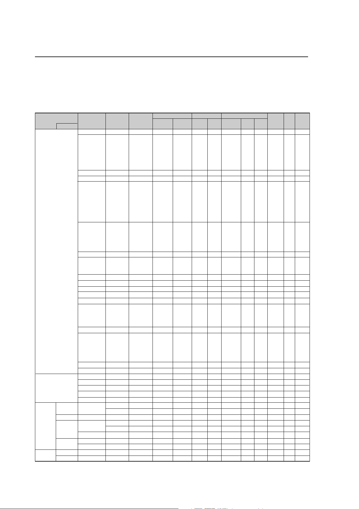
INPUT Response Signals
7 PC signals supported
• When the screen size is 4:3, each signal is converted to a 1024 dots × 768 lines signal. (Except for *
• When the screen size is Dot by Dot, the picture is displayed in the original resolution.
• When the screen size is FULL, each signal is converted to a 1365 dots × 768 lines signal. (Except for *
Computer input signals supported by this system
Model
Signal Type
IBM PC/AT*
compatible
computers
Apple Macintosh*
Work
Station
EWS4800
HP
*
SUN
SGI
IDC-3000G
PAL625P
NTSC525P
8
6*8
8
8
*
Dots 2 lines
640×400
640×480
848×480
852×480*
800×600
1024×768
1152×864
1280×768
1280×800*
1280×854*
1360×765
1360×768
1376×768
1280×1024
1680×1050*
1600×1200
1920×1200*
1920×1200RB
640×480
832×624
1024×768
1152×870
1440×900*
8
*
1280×1024
1280×1024
1152×900
1280×1024
1024×768
1280×1024
768×576
640×480
Vertical
frequency
(Hz)
1
9
9
9
9
9
*
9
70.1
59.9
72.8
75.0
85.0
100.4
120.4
60.0
60.0
56.3
60.3
72.2
75.0
85.1
99.8
120.0
60.0
70.1
75.0
85.0
100.6
75.0
56.2
59.8
69.8*
60.0
60.0
60.0
60.0
59.9
60.0
75.0
85.0
100.1
60.0
60.0
65.0
70.0
75.0
85.0
60.0
60.0
66.7
74.6
74.9
75.1
60.0
60.0
71.2
72.0
66.0
76.0
76.1
60.0
60.0
50.0
59.9
9
Horizontal
frequency
(kHz)
31.5
31.5
37.9
37.5
43.3
51.1
61.3
31.0
31.7
35.2
37.9
48.1
46.9
53.7
63.0
75.7
48.4
56.5
60.0
68.7
80.5
67.5
45.1
48.0
9
56.0*
49.7
53.1
47.7
47.7
48.3
64.0
80.0
91.1
108.5
65.3
75.0
81.3
87.5
93.8
106.3
74.6
74.0
35.0
49.7
60.2
68.7
56.0
64.6
75.1
78.1
61.8
71.7
81.1
49.7
63.9
31.4
31.5
Sync Polarity Presence
Horizontal
Sync on G
Sync on G
Sync on G
Sync on G
C Sync
C Sync
C Sync
NEG
NEG
NEG
NEG
NEG
NEG
NEG
POS
NEG
POS
POS
POS
POS
POS
POS
POS
NEG
NEG
POS
POS
NEG
POS
NEG
NEG
NEG
NEG
NEG
POS
POS
NEG
POS
POS
POS
POS
NEG
POS
POS
POS
POS
POS
NEG
NEG
NEG
NEG
NEG
– –
– –
– –
NEG
NEG
Vertical
NEG
NEG
NEG
NEG
NEG
NEG
NEG
POS
NEG
POS
POS
POS
POS
POS
POS
POS
NEG
NEG
POS
POS
NEG
POS
NEG
POS
POS
NEG
NEG
POS
POS
POS
POS
POS
POS
POS
NEG
POS
POS
POS
POS
POS
NEG
NEG
Sync on G
Sync on G
Sync on G
Sync on G
NEG
NEG
NEG
– –
C Sync
C Sync
C Sync
– –
– –
NEG
NEG
Horizontal
YES
YES
YES
YES
YES
YES
YES
YES
YES
YES
YES
YES
YES
YES
YES
YES
YES
YES
YES
YES
YES
YES
YES
YES
YES
YES
YES
YES
YES
YES
YES
YES
YES
YES
YES
YES
YES
YES
YES
YES
YES
YES
– –
– –
– –
– –
YES
YES
YES
– –
– –
– –
– –
– –
– –
YES
YES
Vertical
YES
YES
YES
YES
YES
YES
YES
YES
YES
YES
YES
YES
YES
YES
YES
YES
YES
YES
YES
YES
YES
YES
YES
YES
YES
YES
YES
YES
YES
YES
YES
YES
YES
YES
YES
YES
YES
YES
YES
YES
YES
YES
– –
– –
– –
– –
YES
YES
YES
– –
– –
– –
– –
– –
– –
YES
YES
Screen size
4:3
2
YES*
YES
YES
YES
YES
YES
YES
– –
– –
YES
YES
YES
YES
YES
YES
YES
3
YES*
3
YES*
3
YES*
3
YES*
3
YES*
YES
– –
– –
– –
– –
– –
– –
– –
– –
4
YES*
4
YES*
4
YES*
4
YES*
– –
YES
YES
YES
YES
YES
– –
– –
YES
YES
3
YES*
YES
– –
4
YES*
4
YES*
4
YES*
YES
YES
4
YES*
3
YES*
4
YES*
7
YES*
7
YES*
D BY D
YES
YES
YES
YES
YES
YES
YES
YES
YES
YES
YES
YES
YES
YES
YES
YES
– –
– –
– –
– –
– –
– –
YES
YES
YES
– –
– –
– –
– –
– –
– –
– –
– –
– –
– –
– –
– –
– –
– –
– –
– –
– –
YES
YES
– –
– –
– –
– –
– –
– –
– –
– –
– –
– –
– –
– –
– –
FULL
(16:9)
YES
YES
YES
YES
YES
YES
YES
YES
YES
YES
YES
YES
YES
YES
YES
YES
YES
YES
YES
YES
YES
YES
YES
YES
YES
YES
YES
YES*
YES*
YES
YES
YES
YES
YES
YES
YES
YES
YES
YES
YES
YES
YES
YES
YES
YES
YES
YES
YES
YES
YES
YES
YES
YES
YES
YES
YES*
YES*
2, 3, 4
3
3
7
7
)
3
)
RGB
select*
– –
STILL
– –
STILL
– –
– –
– –
WIDE2
WIDE1
STILL
STILL
– –
– –
– –
– –
– –
STILL
– –
STILL
– –
– –
STILL
WIDE1
WIDE4
WIDE1
WIDE1
WIDE2
WIDE1
WIDE1
WIDE2
STILL
– –
– –
– –
WIDE4
– –
– –
– –
– –
– –
WIDE2
WIDE3
– –
– –
WIDE1
WIDE1
– –
– –
– –
– –
– –
– –
– –
– –
– –
– –
MOTION
5
Memory
DVI
4
NO
5
YES
7
YES
8
YES
9
YES
41
YES
42
YES
19
YES
17
YES
11
YES
12
YES
13
YES
14
YES
15
YES
43
YES
44
YES
24
YES
25
YES
26
YES
27
YES
45
YES
51
YES
52
NO
23
YES
66
YES
21
YES
37
YES
22
NO
22
YES
53
YES
29
YES
30
YES
40
YES
47
NO
38
YES
54
YES
55
NO
56
NO
57
NO
58
NO
81
NO
88
YES
6
NO
16
NO
28
NO
39
NO
89
YES
29
YES
48
YES
59
YES
60
YES
61
YES
30
YES
62
YES
29
YES
31
NO
32
NO
4
Page 5

Specifications
*1 Only when using a graphic accelerator board that is capable of displaying 852 × 480.
*2 This signal is converted to a 1024 dots × 640 lines signal.
*3 The picture is displayed in the original resolution.
*4 The aspect ratio is 5:4. This signal is converted to a 960 dots × 768 lines signal.
*5 Normally the RGB select mode suite for the input signals is set automatically. If the picture is not displayed properly, set the
RGB mode prepared for the input signals listed in the table above.
*6 To connect the monitor to Macintosh computer, use the monitor adapter (D-Sub 15-pin) to your computer's video port.
*7 Other screen sizes (ZOOM and WIDE) are available as well.
*8 When viewing a moving picture at a vertical frequency greater than 65Hz, the picture may sometimes be unstable (jumpy).
If this occurs, please set the refresh rate of the external equipment to 60Hz.
To view 480I@60Hz (480 interlaced lines, 60Hz refresh rate) or 576I@50Hz (567 interlaced lines, 50Hz refresh rate) when
sync polarity is “Sync on Green”, set “RGB SELECT” to “MOTION”.
*9 CVT standard compliant.
NOTE:
• While the input signals comply with the resolution listed in the table above, you may have to adjust the position and
size of the picture or the fine picture because of errors in synchronization of your computer.
• When a 1280 dots × 1024 lines signal or 1600 dots × 1200 lines signal is input to the monitor, the picture will be
compressed.
• This monitor has a resolution of 1365 dots × 768 lines. It is recommended that the input signal should be XGA, wide
XGA, or equivalent.
• With digital input some signals are not accepted.
• The sync may be disturbed when a nonstandard signal other than the aforementioned is input.
• If you are connecting a composite sync signal, use the HD terminal.
• “IBM PC/AT” and “XGA” are registered trademarks of International Business Machines, Inc. of the United States.
• “Apple Macintosh” is a registered trademark of Apple Computer, Inc. of the United States.
7 Video signals supported 7 DVI HDCP signals supported
Vertical
Frequency
V
(Hz)
f
50
60
Horizontal
Frequency
fH (kHz)
15.625
28.13
31.25
15.734
31.5
33.75
45.0
Signal Format
Component
RGB
Component
RGB
Component
RGB
Component
RGB
Component
RGB
Component
RGB
Component
RGB
Remarks
625I (576I)/SDTV
1125I (1080I)/ HDTV
625P (576P)/SDTV
525I (480I)/SDTV
525P (480P)/SDTV
1125I (1080I)/ HDTV
1125I (1035I)/ HDTV
750P (720P)/HDTV
Vertical
Frequency
f
V
(Hz)
50
60
* No support of EDID
Horizontal
Frequency
f
H
(kHz)
31.3
37.5
28.1
15.6
31.5
45.0
33.8
15.8
720 x 576P
1280 x 720P*
1920 x 1080I
720 (1440) x 576I
640 x 480P (EIA/CEA-861)
720 x 480P
1280 x 720P
1920 x 1080I
720 (1440) x 480I
Remarks
5
Page 6
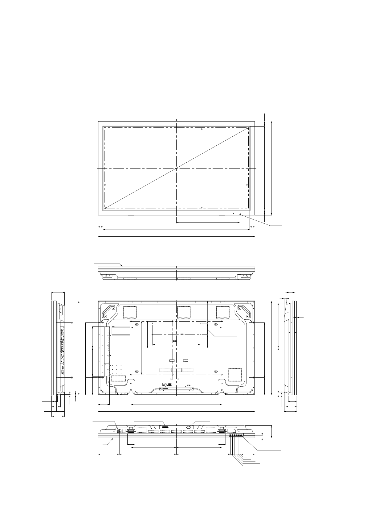
External Dimensions
1.2 External Dimensions
Weight: 61.0 kg
Material: Front: Resin; Rear cover: Metal plate, Front protector panel: Glass
Treatment: Front: Paint; Rear cover: Paint (All paints are Pioneer original colors)
(Unit: mm)
118.9
880
49
FILTER SURFACE
1351 (SCREEN AREA)
850 (for Option M8x6)
250
445 (for PC M4x4)
1550
1372
1470
760 (SCREEN AREA)
592.5
214
102 (for PC)
124
880
49 782 49
LED&IR
49
27.9
8˚
4.5
420420
880
80.9
500 (for Option M8x6)
35
850
1470
AC INLETSPEAKER TERMINAL
70 70
425 425
130
20
20
20
162.5 515 (for SPEAKER M4x4)
20
1
26.5
119
LOCAL CONTROL
20
20
103
119
81.1
54.9
515 (for SPEAKER M4x4)
175.2 264.8 200.8
162.5
162.5 515 (for SPEAKER)
1
5.2
81.1
74
45
119
109
POWER BUTTON
IR
200.5 534.5 505
6
Page 7
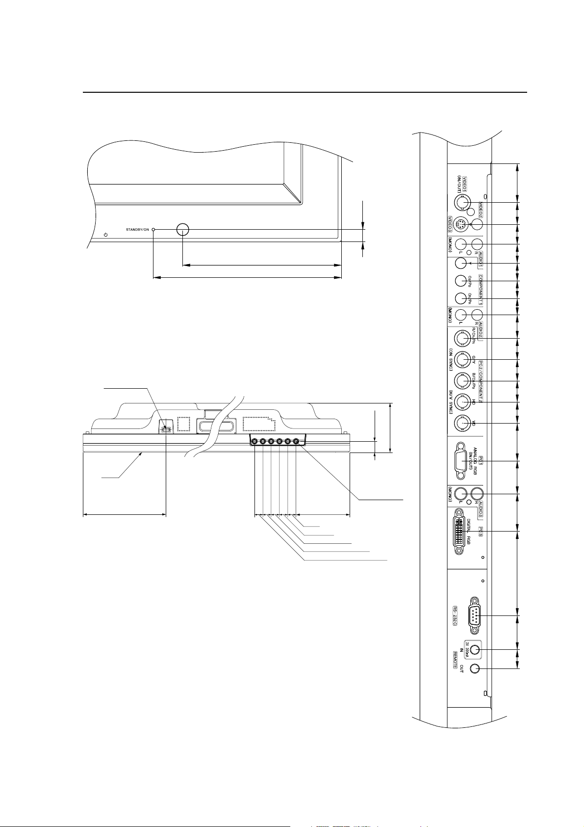
External Dimensions
<Light Sensor for the Remote>
<Main Unit Operation Panel>
POWER
BUTTON
<Connection Panel>
3318.51716151514201818181832283271.52916
10.5
135
160
26.5
119
IR
LOCAL
CONTROL
200.5
130
20
20
20
20
20
7
Page 8
Part Names and Function
1.3 Part Names and Function
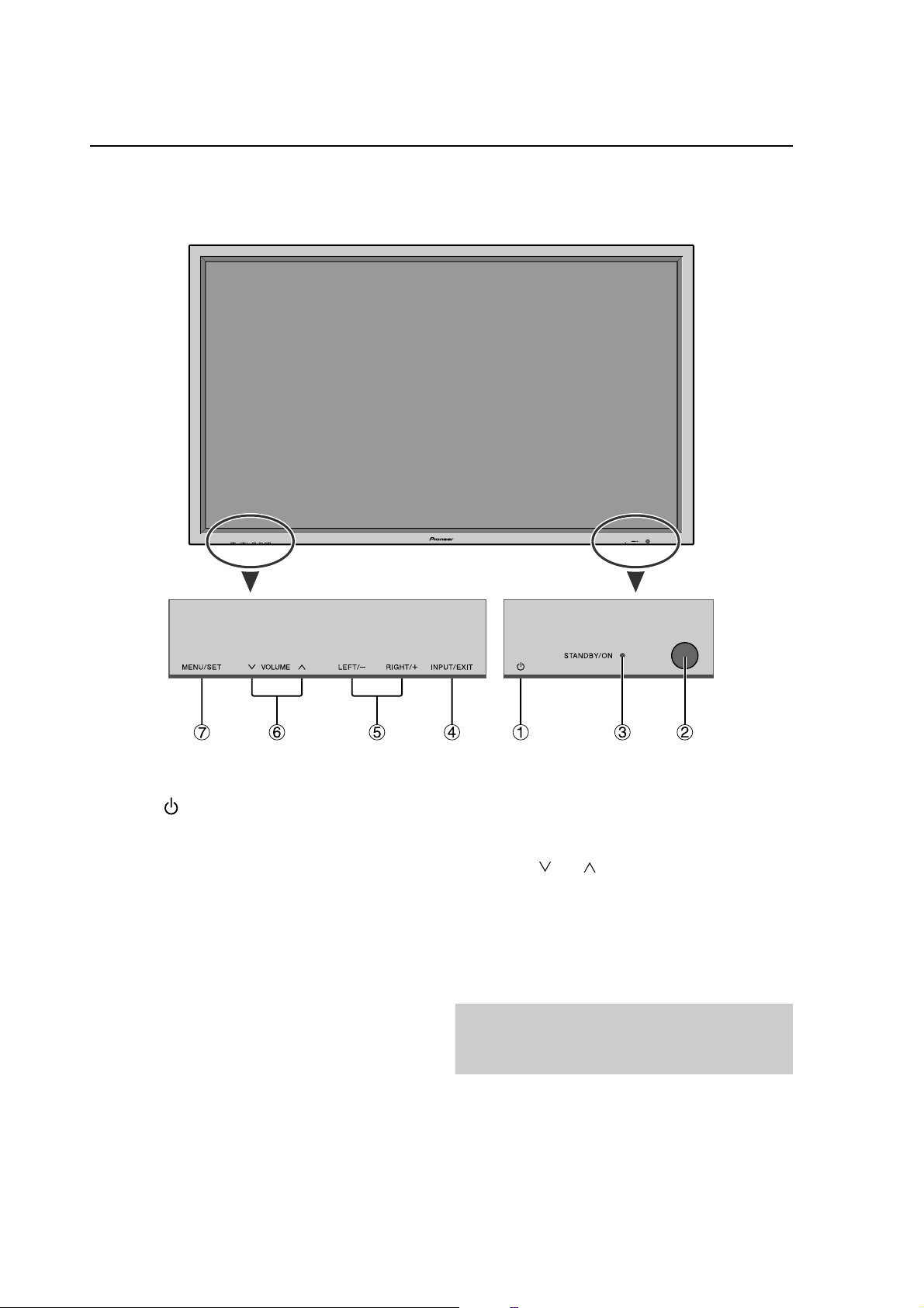
Front View
1 Power ( )
Turns the monitor’s power on and off.
2 Remote sensor window
Receives the signals from the remote control.
3 STANDBY/ON indicator
When the power is on .......................... Lights green.
When the power is in the standby mode .... Lights red.
4 INPUT/EXIT
Switches the input.
The available inputs depend on the setting of “BNC
INPUT”, “RGB SELECT” and “DVI SET UP”.
Functions as the EXIT buttons in the On-Screen Display
(OSD) mode.
8
5 LEFT/– and RIGHT/+
Functions as the CURSOR (2 / 3) buttons in the OnScreen Display (OSD) mode.
6 VOLUME
Adjusts the volume. Functions as the CURSOR (5/∞)
buttons in the On-Screen Display (OSD) mode.
7 MENU/SET
Sets the On-Screen Display (OSD) mode and displays
the main menu.
WARNING
The Power on/off switch does not disconnect the
plasma display completely from the supply mains.
and
Page 9

Rear View/ Terminal Board
Part Names and Function
A AC IN
Connect the included power cord here.
B EXT SPEAKER L and R
Connect speakers (optional) here. Maintain the correct
polarity. Connect the
EXT SPEAKER terminal and the (negative) speaker
wire to the
RIGHT channels.
Please refer to your speaker’s owner’s manual.
C VIDEO1, 2, 3 (BNC, RCA, S-Video)
Connect VCR’s, DVD’s or Video Cameras, etc. here.
VIDEO1 can be used for Input or Output.
D AUDIO1, AUDIO2, AUDIO3
These are audio input terminals.
The input is selectable. Set which video image to allot
them from the SOUND menu screen.
E COMPONENT1
Connect DVD’s, High Definition or Laser Discs, etc.
here.
F PC2/COMPONENT2
PC2: You can connect an analog RGB signal
COMPONENT2
EXT SPEAKER terminal on both LEFT and
and the syncronization signal.
: You can connect DVDs, High Definition
sources, Laser Discs, etc. here.
This input can be set for use with an
RGB or component source.
(positive) speaker wire to the
G PC1 (mini D-Sub 15pin)
Connect an analog RGB signal from a computer, etc.
here. This input can be used for Input or Output.
H PC3 (DVI 24pin)
Connect a digital signal (TMDS) from a source with a
DVI output.
I RS-232C
Never connect any component to this connector
without first consulting your Pioneer installation
technician.
This connector is used for plasma display setup
adjustments.
J REMOTE IN
Connect the remote cable* to the remote control’s
remote jack to obtain wired remote control.
K REMOTE OUT
Connect the remote cable* to the REMOTE IN jack of
the other display monitor to obtain wired remote
control.
* The 1/8 Stereo Mini cable must be purchased separately.
9
Page 10
Pin layout
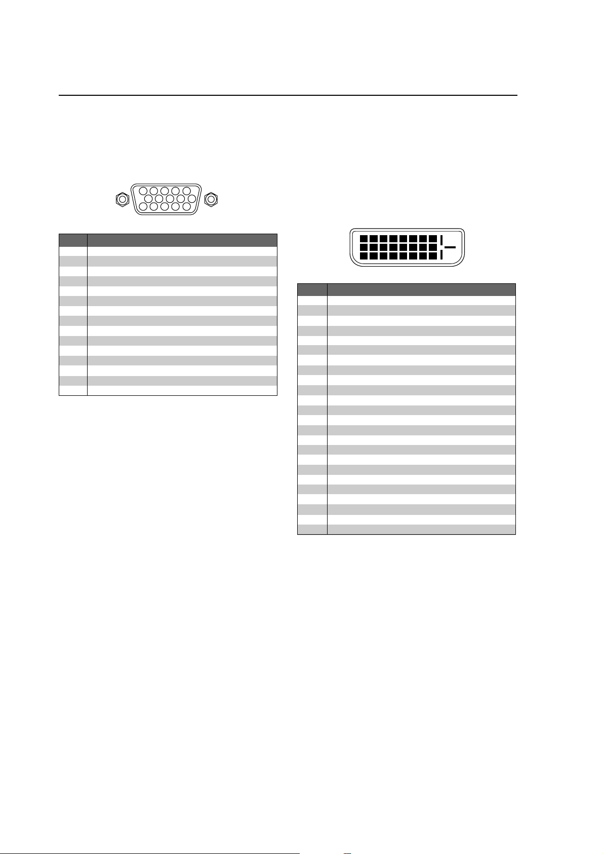
1.4 Pin layout
mini D-Sub 15-pin connector (Analog)
PC 1
5 4 3 2 1
10 9 8 7 6
15 14 13 12 11
Pin No.
1
2
3
4
5
6
7
8
9
10
11
12
13
14
15
Red
Green or sync-on-green
Blue
No connection
Ground
Red ground
Green ground
Blue ground
No connection
Sync signal ground
No connection
Bi-directional DATA (SDA)
Horizontal sync or Composite sync
Vertical sync
Data clock
Signal (Analog)
DVI-D 24-pin connector (Digital)
The unit is equipped with a type of connector commonly
used for digital.
(This cannot be used for an analog input.)
(TMDS can be used for one link only.)
PC 3
12345678
910111213141516
20191817 21 22 23 24
Pin No.
1
2
3
4
5
6
7
8
9
10
11
12
13
14
15
16
17
18
19
20
21
22
23
24
T.M.D.S Data 2 T.M.D.S Data 2 +
T.M.D.S Data 2 Shield
No connection
No connection
DDC Clock
DDC Data
No connection
T.M.D.S Data 1 T.M.D.S Data 1 +
T.M.D.S Data 1 Shield
No connection
No connection
+5V Power
Ground
Hot Plug Detect
T.M.D.S Data 0 T.M.D.S Data 0 +
T.M.D.S Data 0 Shield
No connection
No connection
T.M.D.S Clock Shield
T.M.D.S Clock +
T.M.D.S Clock -
Signal (Digital)
10
Page 11
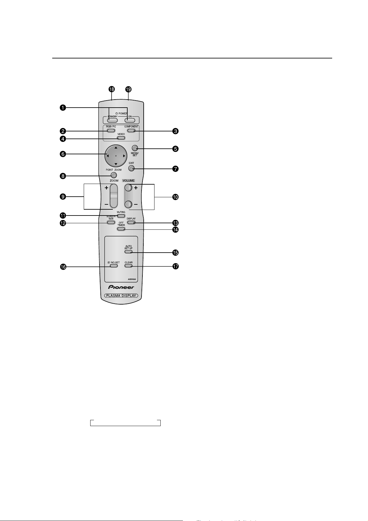
1.5 Remote Control Unit
~ POWER ON/STANDBY
Switches the power on/standby.
(This does not operate when STANDBY/ON indicator
of the main unit is off.)
Ÿ RGB/PC
Press this button to select RGB/PC as the source.
RGB/PC can also be selected using the INPUT/EXIT
button on the monitor.
! COMPONENT
Press this button to select COMPONENT as the
source. COMPONENT can also be selected using
the INPUT/EXIT button on the monitor.
⁄ VIDEO
Press this button to select VIDEO as the source.
→ VIDEO1 → VIDEO2 → VIDEO3
Remote Control Unit
¤ CURSOR (5 / ∞ / 2 / 3)
Use these buttons to select items or settings and to
adjust settings.
# EXIT
Press this button to exit the OSD controls in the main
menu. Press this button during the display of the sub
menu to return to the previous menu.
‹ POINT ZOOM
Press this button to display the pointer.
$ ZOOM (+ /–)
Enlarges or reduces the image.
› VOLUME (+ /–)
Adjusts the sound volume.
% MUTING
Mutes the sound.
fi SCREEN SIZE
Automatically detects the signal and sets the aspect ratio.
SCREEN SIZE button is not active for all signals.
^ DISPLAY
Displays the source settings on the screen.
fl OFF TIMER
Activates the off timer for the unit.
& AUTO SET UP
Press this button to adjust PHASE, CLOCK, Position,
and Contrast automatically, or to switch the screen size
to ZOOM mode automatically with the superimposed
caption displayed fully only when the picture contains
dark areas above and below the picture.
‡ ID NO. SET
Set the ID number in the remote control. The remote
control can then be used only for a display with the
same ID number. When several displays are used
together they can be controlled individually.
* CLEAR
Clears the number set by the ID NO. SET button.
° Remote control signal transmitter
Transmits the remote control signals.
( Remote Jack
Insert the plug of the remote cable (The 1/8 Stereo
Mini cable) here when using the supplied remote
control in the wired condition.
VIDEO can also be selected using the INPUT/EXIT
button on the monitor.
@ MENU/SET
Press this button to access the OSD controls.
Press this button during the display of the main menu
to go to the sub menu.
11
Page 12

Installation Site Requirements
2.1 Installation Site Requirements
If the site requires modifications or special preparations for installation of the plasma display or its mounting hardware,
obtain permission in advance from the building owner or building authorities. To ensure installations safety, it is also
important to determine the strength of the installation site with the help of the original building contractor.
Safety Precautions
1) Structure of the installation site
Make sure you thoroughly understand the structure of the installation site before determining the most suitable installation
method. Buildings vary in structure and materials, and the appropriate mounting hardware with differ accordingly. When
drilling into walls, always remain aware of the internal electric wiring and pipes.
2) Weight capacity of the installation site
Select a location with a weight capacity sufficient to support the total weight of the display and mounting hardware.
3) Flat, level surfaces
Select a flat, level surface for installation, such that mounting software will be parallel to the surface to which it is affixed.
Install the unit so that the load is evenly distributed along the ceiling or floor, as well as on mounting hardware such as hang
bolts.
4) Sufficient work space
Select a location with sufficient space for installation work.
5) Nearby equipment
If air conditioning ducts or lamps, etc. are located near the installation site, the attendant dust, extreme temperatures,
humidity, and condensation may become sources of trouble. Please take sufficient steps to avoid this.
6) Safe locations
Do not install the unit where it may be easily touched or leaned against. Avoid locations subject to high vibration or severe
impacts.
7) Lighting conditions
• Consider existing lighting and sunlight angles when creating the installation layout. Extremely bright lighting can reduce
the visibility and quality of the display image.
• In extremely bright surroundings, adjusting screen intensity may not result in perceptibly brighter images. Keep in mind
that extreme intensity settings can reduce system service life.
8) Other installation conditions
The unit is designed for indoor use, and is not suited for open-air use. Installation in locations that are even partially exposed
to the elements may lead to malfunctions or breakdown caused by any of the following. And if there is danger of it being
exposed to similar effects even when installed indoors, it is necessary to block the outside air by cooling the casing etc.
• Water and dust
• Changes in temperature and humidity
• Salt-bearing wind
Direct sunlight upon the display degrades image quality. In installing the display, avoid sites exposed to direct sunlight.
9) Temperature and humidity conditions
• The installation site should meet the following conditions:
• Operating temperatures: 0 to 40 °C (largely depending on installation conditions)
• Operating humidity: 20 to 80 %
• Storage temperature: –10 to 50 °C
• Storage humidity: 10 to 90 %
• Operating atmospheric pressure: 720 to 1114 hPa
• Storage atmospheric pressure: 700 to 1114 hPa
• We recommend against installing electronic products such as this unit in locations subject to high humidity. If the unit is
to be installed in a location subject to relatively high humidity, observe the following:
• Failure to install the unit in unacceptable ways may result in non-warranty damages.
• Make sure the unit is grounded.
• Do not allow water or other liquids to enter the unit.
12
Page 13

Installation Site Requirements
10) Prevent condensation
One of the chief sources of problems during the winter is ‘condensation’. Rapid temperature fluctuations can deposit
water vapor inside the unit or on the screen, degrading performance. If condensation occurs, turn the unit off and leave
it off for an hour or so. It is also good practice to increase the room temperature gradually.
Beware of condensation. Consult Pioneer authorized dealers for assistance.
11) Power requirements
• This unit functions properly when powered at ±10 % of its rated voltage. Characteristics of power lines may effect
the voltage output. If any of the following occurs, contact an electrician to inspect the power.
• Significant voltage drop between the circuit panel and the plasma display
• Significant changes in voltage when switching the unit power on or off
• Please consider the following to allow a margin for power consumption per unit.
540 W ≠ 540 VA
(NOTE)
• The in-rush current upon powering will be approximately 50 A.
• A grounded three-core power cable is used by the plasma display in order to maintain its functions.
Connect the power cord by inserting it in a grounded electrical outlet, making sure that the cord is properly grounded.
When using a power source use conversion plug, insert it in a grounded electrical outlet and securely attach the
ground wire.
• A leakage current within a value stipulated by standards in each country flows from an internal noise filter through
devices installed inside switching power sources such as television sets or air-conditioners. Because these currents
are added together when multiple units are used, be careful to avoid an electric shock and take steps to prevent
electric shock caused by ground wires etc.
When a leakage breaker will be installed in a power distribution series, choose the leakage breaker rating so that it
has a non-operating current that is at least two times the total leakage current in order to prevent frequent malfunctions.
And when many devices are connected, increase the number of leakage breakers and form branches in the wiring
system.
12) Effective remote control distance
The remote control supplied with this display receives at the following angles and distances.
Front/left 30° / right 30°: 7m (Min)
Upwards 30°: 3.5m (Min)
Downwards 30°: 4.5m (Min)
This display emits weak infrared radiation. If other products controlled with infrared remote controls are placed nearby,
remote control function may be affected. In such cases, move them further away from the display or contact Pioneer
authorized dealer for assistance.
Depending on installation conditions, the range of the unit's own remote control may be reduced by infrared radiation
emitted by the screen.
The screen's infrared intensity will vary, depending on the image displayed.
13
Page 14
Installation Conditions
2.2 Installation Conditions
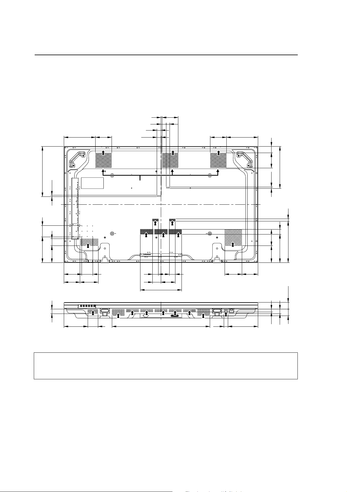
2.2.1 Heat dissipation
This unit has openings for effective ventilation at locations marked by arrows in the illustration below. The direction of the
arrows shows the direction of airflow. To allow proper dissipation of heat from the unit, do not cover any of these
openings.
(Unit : mm)
239
122
30
32.5
1229
25.5
40
122
239
381
85
196
11.5
53.5
128
34
FF F
FF
115 49
318
Fan (3 in number)
F
11.5
F
38
123.5
313 18
215
128
134
122
F
85
137.5
F FF
46
46
109
65
130.5
F
122
314
51.5
50
22
180
78
742
30
228
34
Three fans draw off hot air from the unit. All openings not assisted by fans serve as air inlets. If the unit is hung from or
embedded into a wall, special operating temperature limits and other limitations may apply. Refer to “2.4 Special installation
(pg. 21)”.
14
Page 15
Installation Conditions
2.2.2 Calculating heat quantity
As a courtesy to our customers, we have included the power formula to calculate the air conditioning needs.
For power consumption, allow for 540 W ≠ 540 VA per unit.
Since most of the power consumed is transformed into heat, power consumption may be regarded as roughly equal to
generated heat.
1 Conversion to calories
[W] × 0.86 = [kcal/h]
Heat generated per display: 540 W × 0.86 = 465 kcal/h
2 Conversion to British Thermal Units
[W] × 3.41 = [BTU/h]
Heat generated per unit: 540 W × 3.41 = 1842 BTU/h
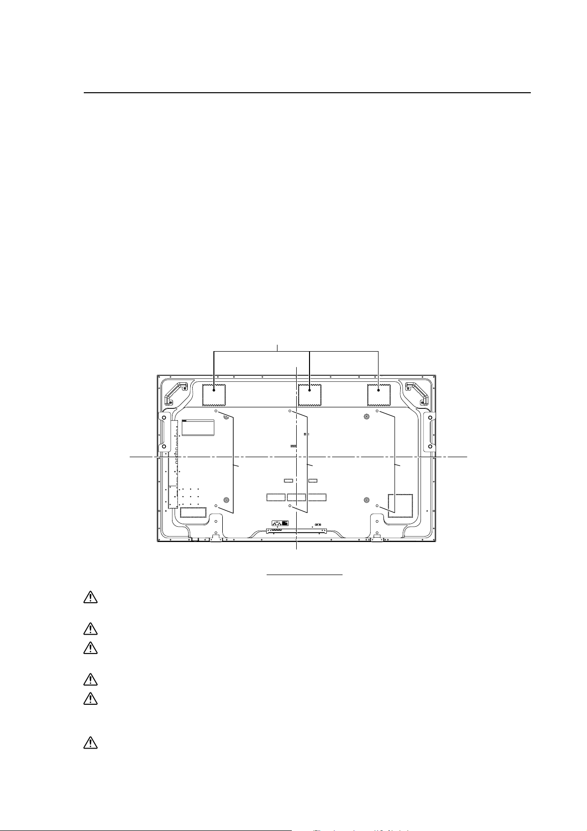
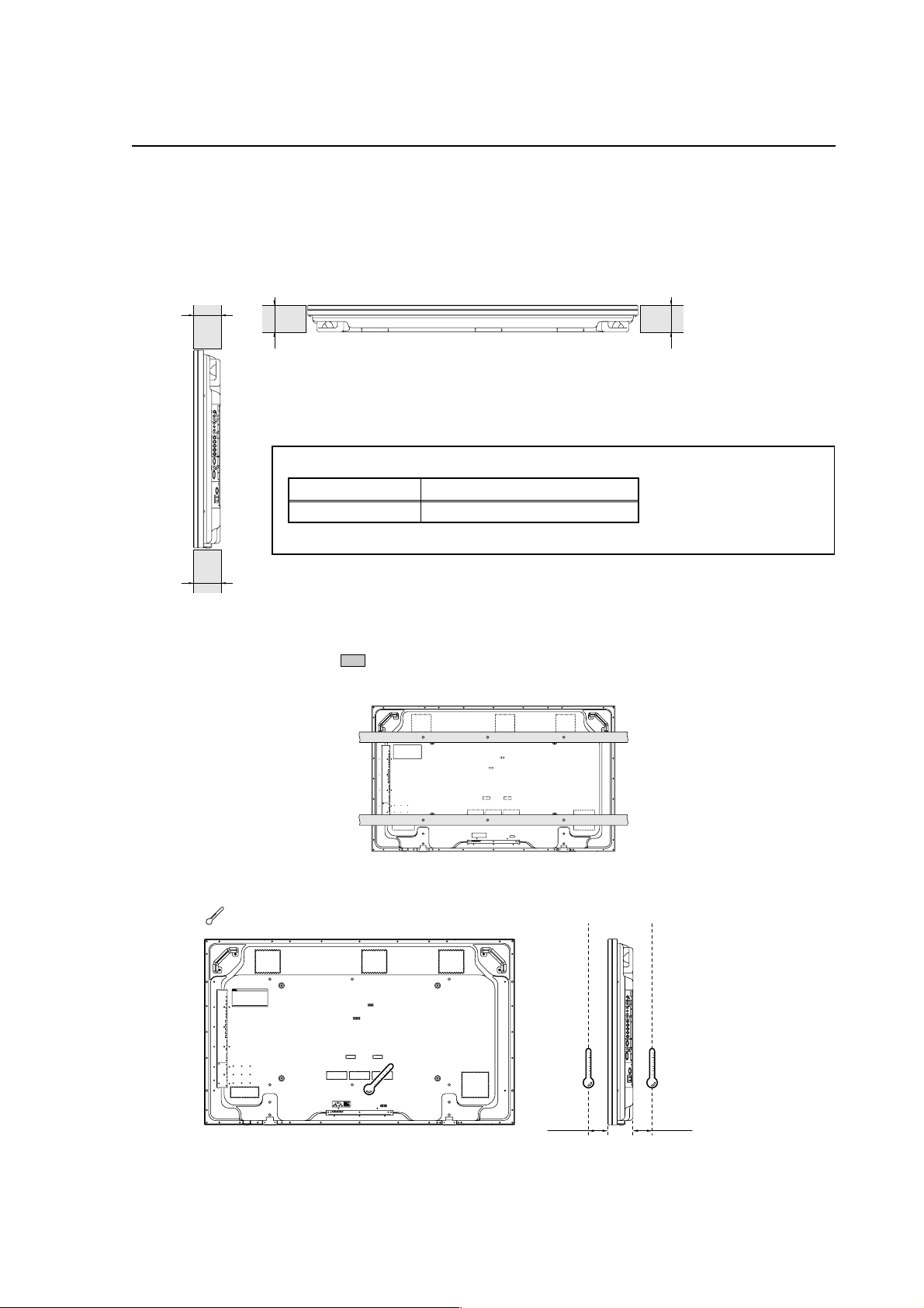
2.2.3 Product mounting holes
We recommend using mounting hardware available from Pioneer. If you use other mounting hardware items, mount
them to the unit using the M8-bolt holes provided in the unit. Tighten the bolts with a torque between 50 and 80 kg/cm.
Applying a torque beyond these limits may lead to internal component failure.
• Locations of useable mount holes are shown below.
Vent (fan)
Center line
Holes Holes Holes
Center line
Rear view diagram
Always use a minimum of 4 mounting holes, evenly distributed on opposite sides of both the horizontal and
vertical center lines.
Use bolts that can be driven 12 to 18mm into holes.
Do not block or cover air outlets and openings for ventilation on the rear panel.
Take precautions to prevent soiling walls behind the product with exhaust air discharged from the air outlets.
This unit incorporates glass components. Install only on flat surfaces.
Always turn every bolt by hand 2 or 3 times and check to make sure it is straight, then tighten it using a tool.
Do not over tighten bolts.
Do not use loctight or similar bonding products.
Please make sure that you use M8 (P=1.25) bolts (other types of bolt cannot be used).
15
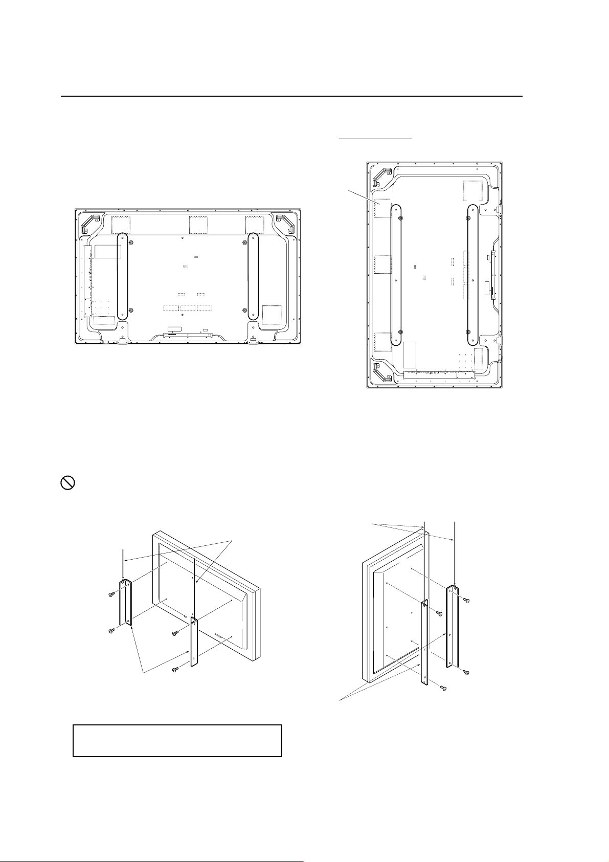
Page 16
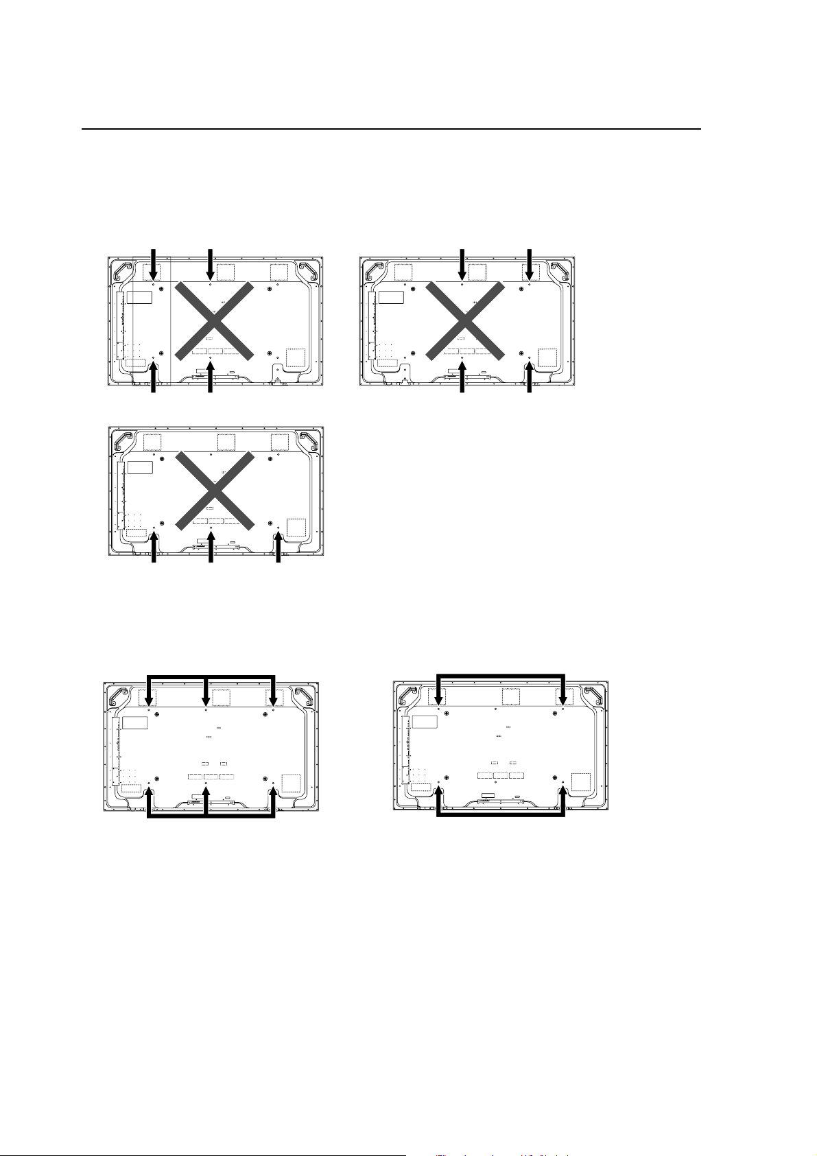
Installation Conditions
This unit is designed to be mounted using four bolt holes. For additional safety, we recommend securing it at four to six
points on opposite sides of the horizontal and vertical center lines, as shown in the illustration below. Do not secure the
unit at four points or at three points arranged in a single row, as shown below
Methods for securing - Unfavorable examples
Methods for securing - Favorable examples
A. Secured at six points
B. Secured at four points
16
Page 17
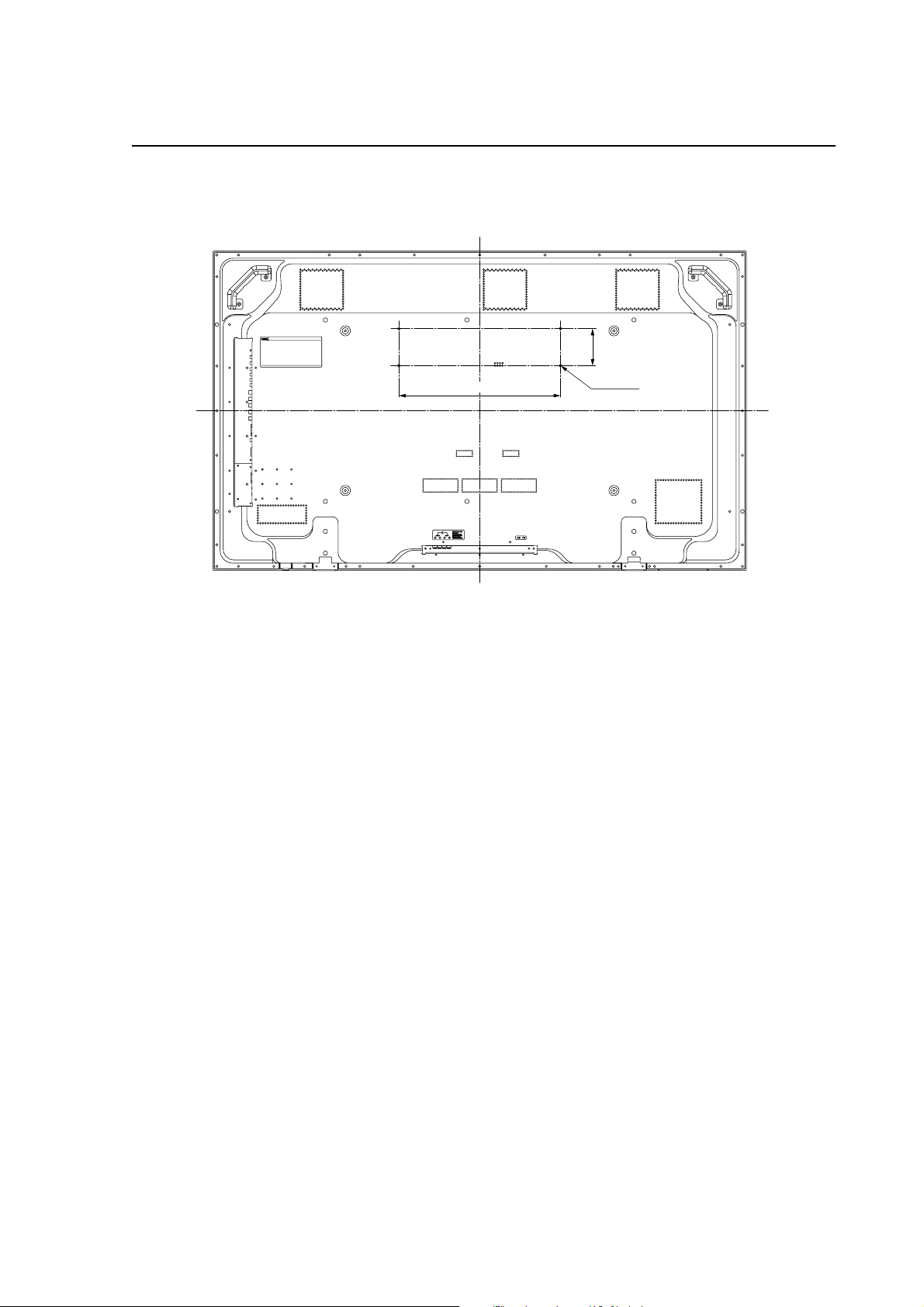
2.2.4 Anchoring PC and similar apparatuses
Installation Conditions
102
445
These holes are used to anchor and attach a PC or other apparatus.
They are M4 bolt holes x4, their horizontal pitch is 445mm and vertical pitch is 102mm.
Usage limitations:
• It is less than 10kg.
• If it covers a ventilation opening on the back cover of the plasma display, it is at least 10mm above the opening.
• The external temperature of the outside of the PC etc. that is installed is a maximum of 50°C at a surrounding
temperature of 40°C or less.
The holes can also be used to help prevent the plasma display from falling over (Refer to “2.3.3 How to use the safety
metal fittings and the screws for safety metal fittings (pg. 18)”)
But the plasma display cannot be anchored to and installed on a wall using only these holes.
An apparatus is installed only by a service man, so nobody except a serviceman may install one.
M4x4
17
Page 18
Installation Procedures
2.3 Installation Procedures
2.3.1 Transportation precautions
1 Any transportation of the unopened unit in its packaging should be done by two or more persons. To avoid injury or
damage, do not lift the package by its packing bands.
2 When transporting or storing the unit, always position it vertically - never horizontally. Horizontal transportation or storage
invalidates the product warranty.
3 In transportation or storage of products in original packing, never stack more than two units high. This warning is also
indicated on the upper face of the carton.
4 For transportation or storage, observe the warnings and instructions on the upper face of the carton.
5 Plasma display is mode of glass. Please take precautions to prevent it from being damaged.
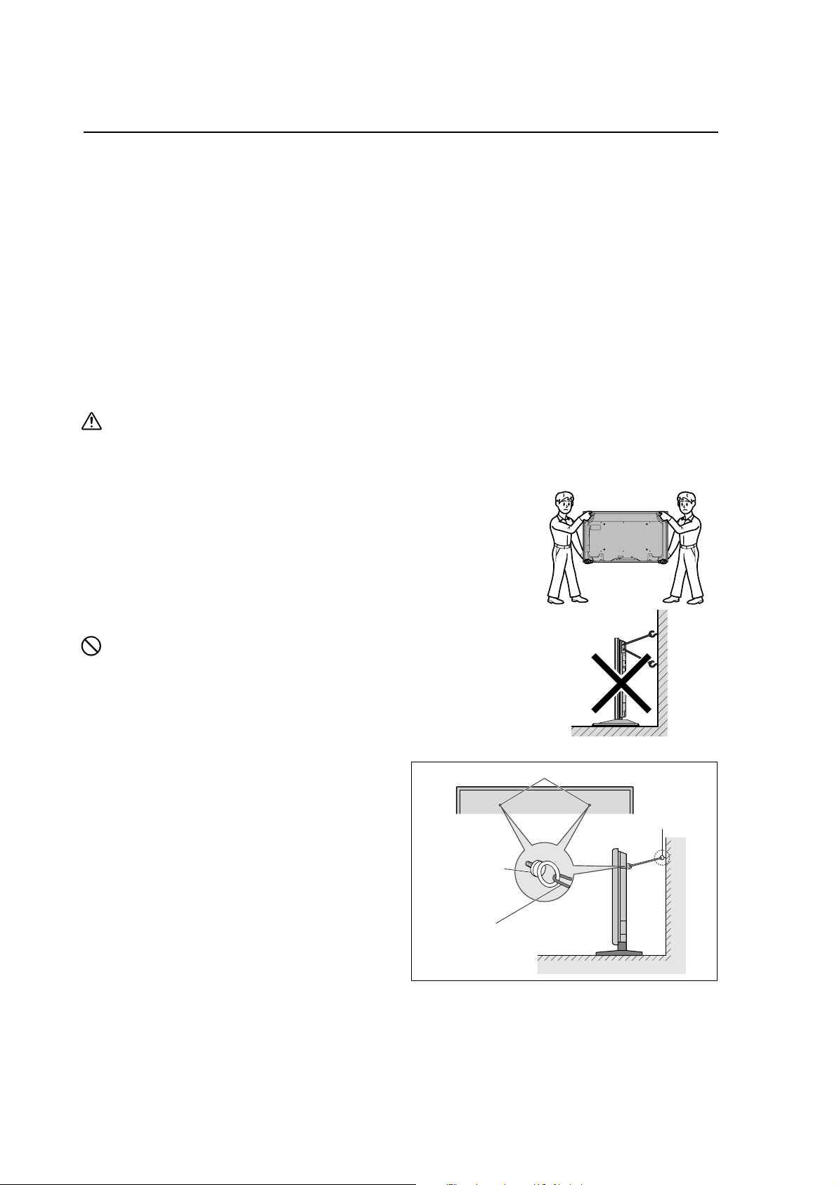
2.3.2 Transportation of the unpacked unit
If it needs to be moved, the unit should be moved by two or more persons.
Caution
• Never move the unit by dragging it along the floor.
• Move the unit slowly, taking care to prevent scraping or striking the delicate front protective panel.
• In order to prevent adhesion of dust, remove the protective film only after all work and preparations for the installation
site, including clean-up following unpacking, are complete.
• Handles should not be removed or reattached by anyone other than the professional
installation technician or service personnel.
• If handles must be removed due to specific installation conditions, the mounting
screws should be stored carefully together with the handles. Also, when re-attaching
the handle, be sure to completely tighten the screws to ensure safety
• When moving the display, it should always be carried by two persons holding the
rear handles in the manner shown.
No!
• Never attempt to move the plasma display by holding only one of the handles.
• When installing the plasma display, do not use the handles as means of hanging the
display; also do not use them as devices to prevent tipping over (see illustration).
2.3.3 How to use the safety metal fittings and the
Screw hole
screws for safety metal fittings
• These are fittings for fastening the unit to a wall to prevent
tipping due to external shock when using the stand
(optional). Fasten the safety fittings to the holes in the
back of the monitor using the safety fitting mount screws.
• Be careful of the ropes when moving it.
• This device cannot be installed only on the display. Be
sure to always install it using a stand specified by this
company or a specialized unit.
• A serviceman installs this unit, so do not let anyone else
install it. The person might be injured.
Safty metal fittings
Metal chain
(Not supplied)
Table Top
Screw or Hook etc.
(Not supplied)
Wall
18
Page 19
Installation Procedures
2.3.4 Wiring
1) Connecting the power cable
• Check to make sure the electrical outlet is located so that it is easy to remove the power plug.
• Insert the power plug firmly. An incomplete connection causes noise.
• Attach the ferrite core (included with the product) to the power cord.
• For power source specifications, refer to 2.1 “Installation Site Requirements, Section 11) Power requirements (pg.
13)”, above.
2) Connecting signal cables
(1) Please refer to “p.3 of the instruction manual” for instructions on how to connect a PC or a video device.
(2) Important notes
• Use coaxial cables. As a rough guide, for video signals use 3C-2V cables for lengths up to 15 meters, and 5C-2V
cables for lengths up to 30 meters. Use thicker cables for computer signals, since these signals are more likely
to degrade: 5C-2V cables, for example, for 15-meter lengths. Generally, thicker cables will produce more reliable
connections. You can also improve signal quality by minimizing cable length.
• Video cables plugged into video inputs and outputs close to dimmers, neon signs, air-conditioning units, or
cables for wired broadcasts may occasionally deliver slightly corrupted images.
3) Processing wires
• In the case of permanent or long-term installation, please be careful to select cables of the correct length, considering
the whole wiring route when doing this (this is not so important in the case of short-term installation such as with
special events).
• Arrange and secure cables so that they will not be subject to direct load or physical force. For temporary installation,
securing cables with string should be perfectly adequate. For permanent installations, secure by more reliable
means.
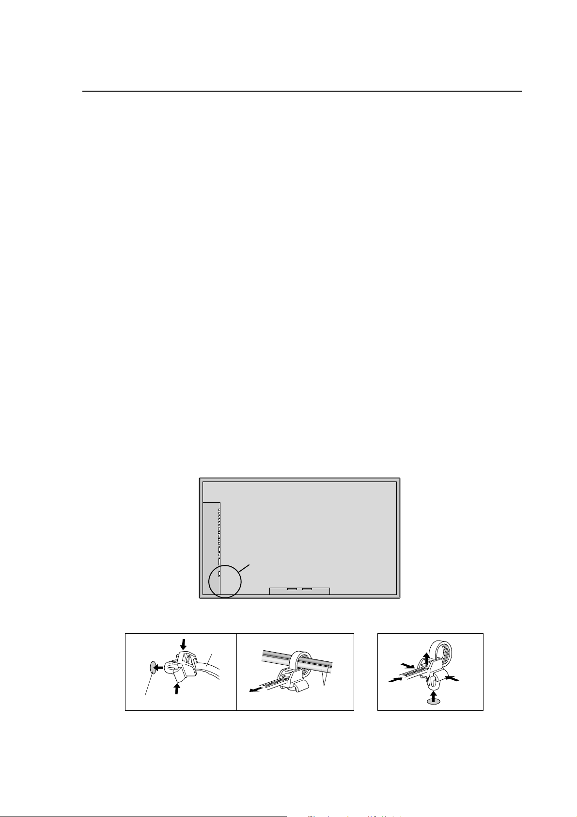
4) Cable Management
Using the cable clamps provided with the plasma display, bundle at the back of the unit the signal and audio cables
connected to the display.
Back of the unit
mounting holes
To attach To detach
1. 2.
mounting hole
clamp
cables
19
Page 20
Installation Procedures
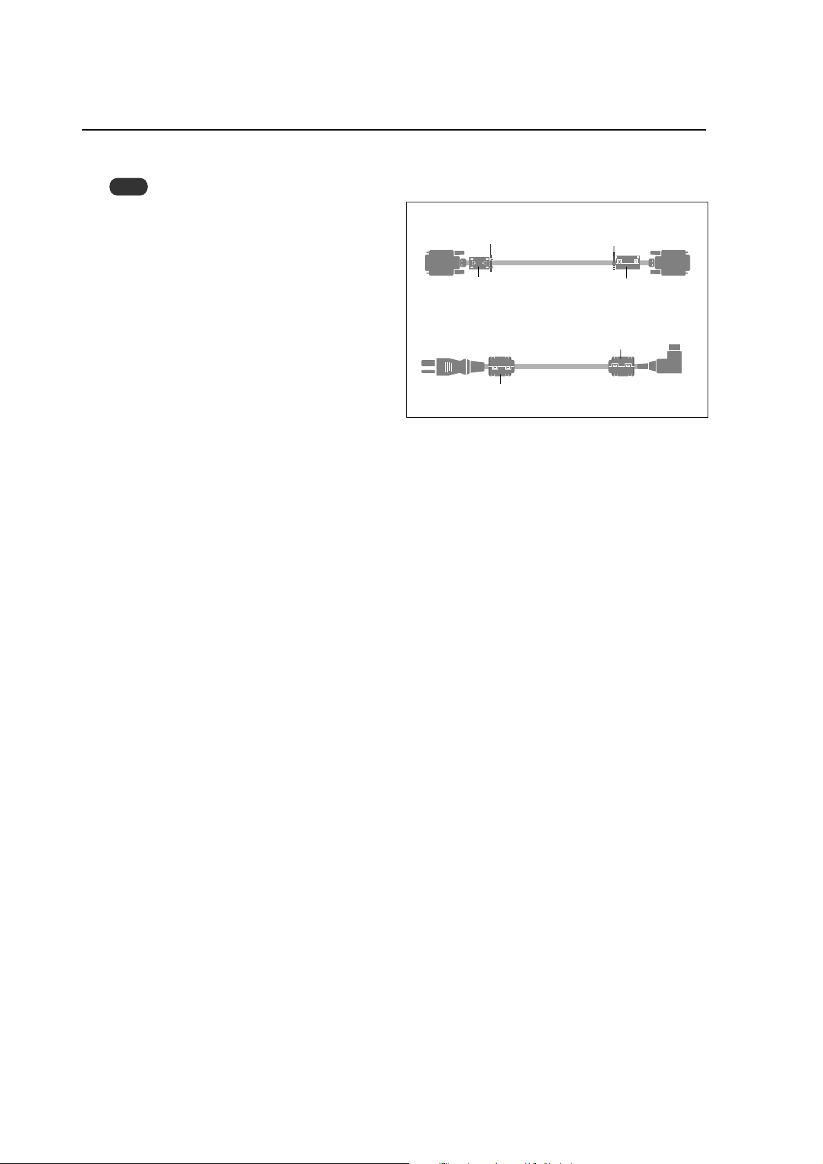
4) Attaching the ferrite cores
Note
When you connect a computer to this monitor, use
an RGB cable including the ferrite core on both ends
of the cable. And regarding DVI and power cable,
attach the supplied ferrite cores. If you do not do this,
this monitor will not conform to mandatory FCC
standards.
Set the ferrite cores on both ends of the DVI cable
(not supplied), and both ends of the power cable
(supplied).
Close the lid tightly until the clamps click.
Use the band to fasten the ferrite core (supplied) to
the DVI cable.
DVI cab le (not supplied)
band
core (small)
Power cable (supplied)
core (large)
band
core (small)
core (large)
Connector
20
Page 21
Special Installation (Mounting to fittings)
2.4 Special Installation
The unit can be hung from or embedded in a wall, but such special installations impose additional limitations on operating
temperatures and other operational factors.
Examine installation methods and the ambient conditions for your installation site, and refer to sections “2.1 Installation Site
Requirements (pg. 12)”, ”2.2 Installation Conditions (pg. 14)”, “2.3 Installation Procedures (pg. 18)” in this manual.
Measurements discussed in this manual assume the following conditions:
• A 100 % white input is supplied.
• Sufficient aging has been completed.
Make all measurements under identical conditions. The aging period required for correct measurement
will be about two and a half hours, depending on the space available at the installation site.
2.4.1 Mounting to fittings
Observe the following guidelines when mounting the unit to fittings.
Notes 2 to 5 apply to all cases of mounting to fitting.
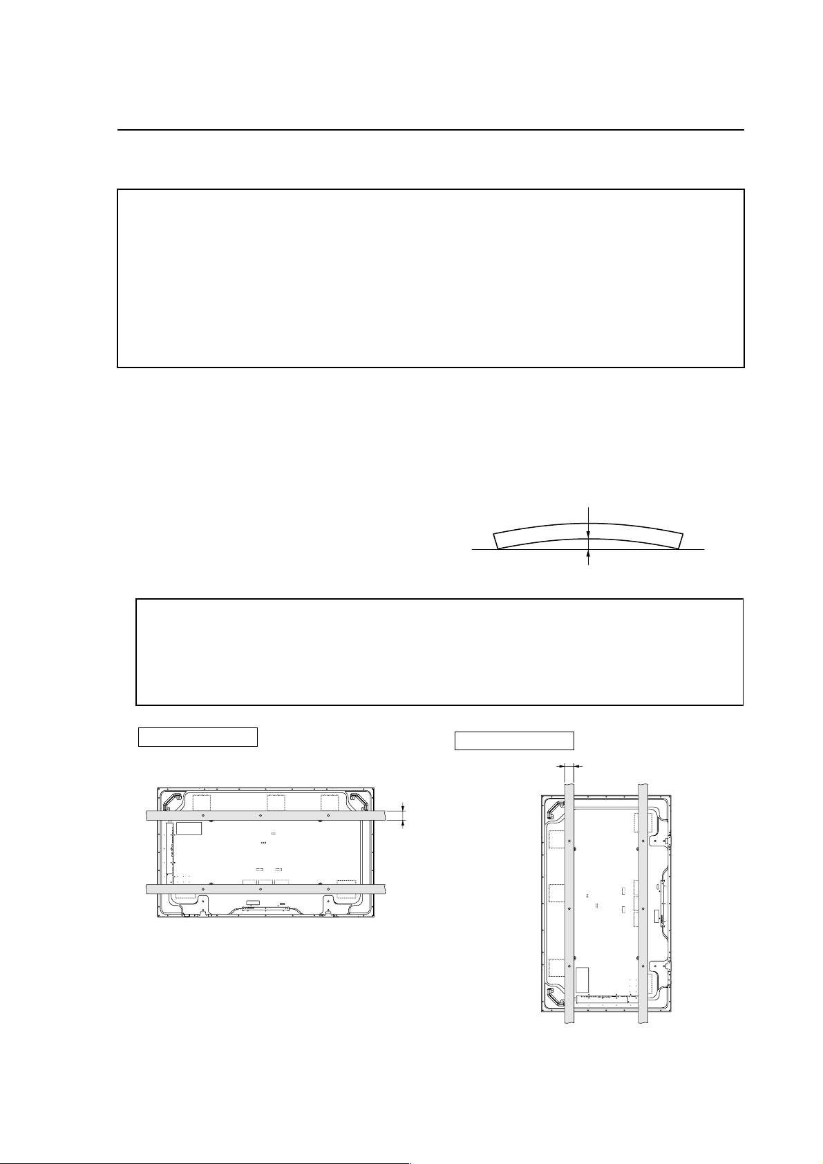
1 When mounting the unit, make sure that there are no objects around it within a distance of 300mm.
2 Any unit deformation/warping occurring as a result of
installation should be less than 4 mm.
3 Never block or cover openings, aside from those shown
as blocked in the illustrations on the following page.
4 The strength of the fittings should be adequate to bear the
weight of the display.
5 Take precautions to avoid sharply bending the power cable.
Maximum allowable deformation/warping is 4 mm.
4 mm MAX
✩ Operating environment for standard installation
• Ambient Temperature: 0 to 40 °C (example 1)
✩ Operating environment for vertical installation
0 to 40 °C (vertical installation: example 2)
The operating temperature restrictions for the speaker system (PDP-S29-LR) are the same regardless of installation
position.
Standard installation
Example 1
35 mm or
less
Vertical installation
Example 2
35 mm or less
21
Page 22
Special Instruction (Hanging on the wall)
2.4.2 Hanging on the wall
Carefully read the following before attempting to hang the unit on a wall, and observe the various limitations specified
below. Be sure to mount the unit so that twisting, bending, or any other deformation does not exceed 4 mm.
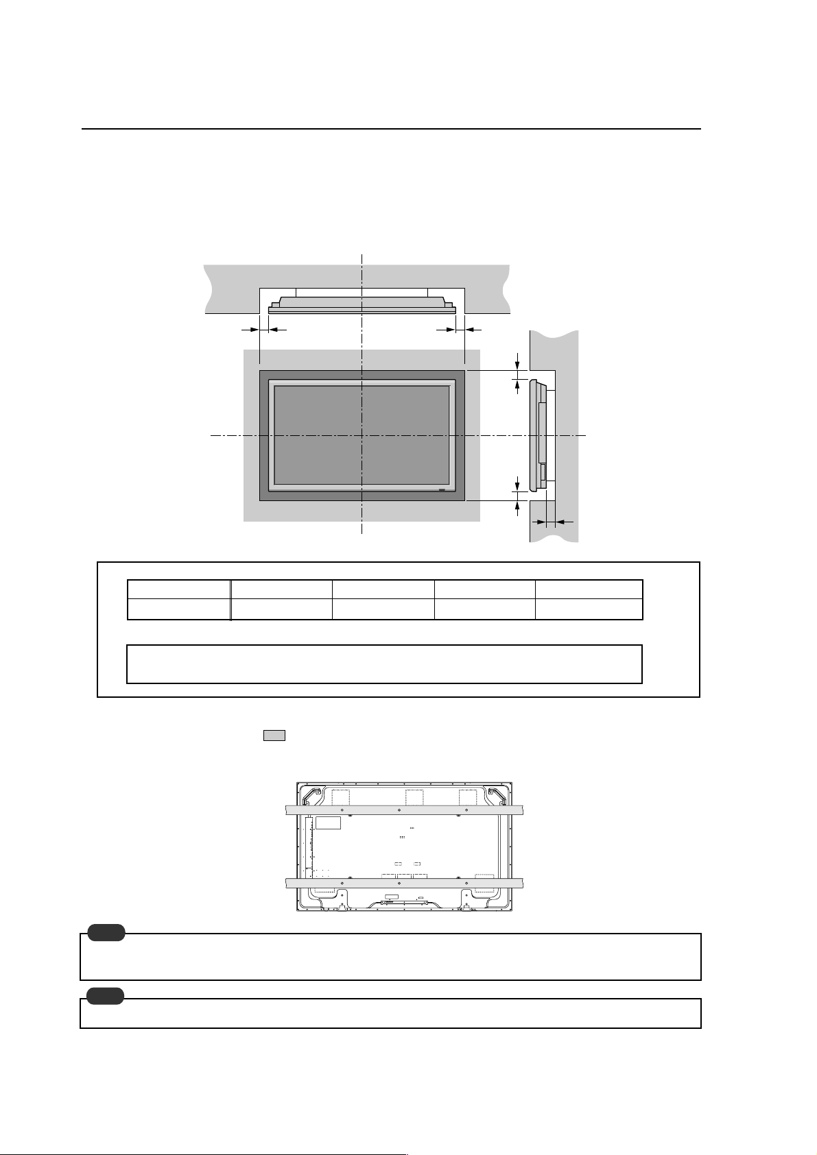
Ventilation Requirements for enclosure mounting
To allow heat to disperse, leave space between surrounding objects as shown on the diagram below when installing.
Wall
DD
Wall
B
C
A
Operating temperature restrictions
✩ Standard single-unit installation
Distance from wall (A) BCDAmbient temperature
50 mm or more 50 mm or more 50 mm or more 50 mm or more 0 to 40°C
✩ Requirements when used with PDP-S29-LR speaker system
Requirements are the same as those for standard single-unit installation.
However, dimensions refer to the distance between the speaker and the wall
Methods of Securing: Basic methods of securing are shown below. Avoid blocking or covering areas aside from those
indicated by
. Before attaching the unit to fittings, double-check that the thickness and height
of the fittings, and the number of fixing bolts is correct. (Also refer to 2.4.1 “Mounting to fittings
(pg. 21)”.)
Note
Heated air is drawn off from the interior of the unit by fans. Before installation, consider the heat resistance of the wall
or other surfaces behind the unit. Exhaust temperatures can be 30 °C higher than the outside temperature.
Note
For wall-mounting, do not bundle the cables in a way that will obstruct ventilation.
22
Page 23
Special Installation (Embedding in the wall)
2.4.3 Embedding in the wall
Carefully read the following before trying to embed the unit in a wall, and make sure to observe all the limitations specified
below.
Be sure to mount the unit so that twisting, bending, or other deformation of the unit does not exceed 4 mm.
(1) Embedding in walls with space provided behind the unit (With no obstructions within a distance of 300 mm from
the back surface of the unit).
A
X (Front of the unit)
A
Y (Rear of the unit)
A
<Viewed from Above>
✩ Operating Temperature Restrictions
Temperature in space X and Y
A: 0 to 300 mm 0 to 40 °C
* The same operating temperature restrictions apply to the speaker system (PDP-S29-LR).
A
<Viewed from the Right Side>
Methods of Securing: Basic methods of securing are shown below. Avoid blocking or covering areas aside from those
indicated by
of the fittings, and the number of fixing bolts is correct. (Also refer to 2.4.1 “Mounting to fittings
(pg. 21)”.)
. Before attaching the unit to fittings, double-check that the thickness and height
Temperature Measurement Points (Illustration for reference purposes)
: Thermometer (temperature measurement point)
50mm 50mm
• Make measurements at a distance of 50 mm from the unit, without directly subjecting the thermometer to fan exhaust.
• For spaces where temperature fluctuations are likely, gather additional measurement points for an adequate data set.
23
Page 24
Special Installation (Ceiling suspension (with wires))
2.4.4 Ceiling suspension (with wires)
When suspending it from a ceiling with wire, the unit must be attached at four or more points with these points distributed
symmetrically on both sides of the vertical and horizontal center lines.
Attach this fan on the left side
A
B
AB
When suspending from a ceiling with wire, use the brackets shown below to prevent concentrating loads on the upper two
fixing points.
For additional safety, secure the wires to separate fittings or parts of the ceiling.
Use mounting screws of material stronger than soft steel, and use hexagonal bolts.
Use wires adequate for the combined weight of the unit 61.0 kg and the weight of the support brackets.
No!
When installing the plasma display, do not use the handles as means of hanging the display.
Wires
Wires
Screws
Brackets
Screws
Brackets
✩ Operating Temperature Restrictions
• Ambient temperature: 0 to 40 °C
24
Page 25

Special Installation (Ceiling suspension (with wires))
Methods of Securing: Basic methods of securing are shown below. Avoid blocking or covering areas aside from those
indicated by . Before attaching the unit to fittings, double-check that the thickness and height
of the fittings, and the number of fixing bolts is correct. (Also refer to 2.4.1 “Mounting to fittings
(pg. 21)”.)
Vertical suspension
25
Page 26
Special Installation (Hanging on the wall (lengthwise))
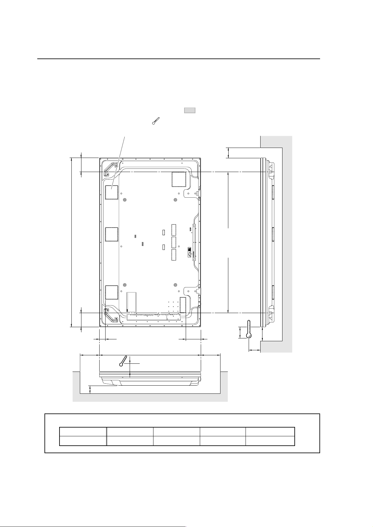
2.4.5 Hanging on the wall (lengthwise)
Carefully read the following before attempting to mount the unit on the wall, and observe the various limitations specified
below.
Be sure to mount the unit so that twisting, bending, or any other deformation does not exceed 4 mm.
Shaded areas indicate attachment points for mounting hardware.
: Thermometer (temperature measurement point)
Attach this fan on the left side
B
122
Avoid blocking or
covering this area
1470
on the upper and
lower sides.
122
49 128
A
✩ Operating Temperature Restrictions
Distance from wall (A) BCDAmbient temperature
50 mm or more 50 mm or more 50 mm or more 50 mm or more 0 to 40 °C
26
10
25
880 DD
C
10
Page 27

Special Installation (Hanging on the wall (lengthwise))
Methods of Securing: Basic methods of securing are shown right. Avoid blocking or
covering areas aside from those indicated by . Before attaching
the unit to fittings, double-check that the thickness and height of
the fittings, and the number of fixing bolts is correct. (Also refer to
2.4.1 “Mounting to fittings (pg. 21)”.)
Note
Heated air is drawn off from the interior of the unit by fans. Before
installation, consider the heat resistance of the wall or other
surfaces behind the unit. Exhaust temperatures can be 30 °C
higher than the outside temperature.
Note
For wall-mounting, do not bundle the cables in a way that will
obstruct ventilation.
27
Page 28

Special Installation (Place product upright and flush into wall (embedding in the wall))
2.4.6 Place product upright and flush into wall (embedding in the wall)
Carefully read the following before trying to embed the unit in a wall, and make sure to observe all the limitations specified
below.
Be sure to mount the unit so that twisting, bending, or other deformation of the unit does not exceed 4 mm.
(1) Embedding in walls with space provided behind the unit (with no obstructions within a distance of 300mm from
the back surface of the unit).
AA
A
X (Front of the unit)
Y (Rear of the unit)
<Viewed from Above>
✩ Operating Temperature Restrictions
Temperature in space X and Y
A: 0 to 300 mm 0 to 40 °C
A
<Viewed from the Right Side>
Methods of Securing: Basic methods of securing are shown right. Avoid blocking or covering
areas aside from those indicated by . Before attaching the unit
to fittings, double-check that the thickness and height of the fittings,
and the number of fixing bolts is correct. (Also refer to 2.4.1
“Mounting to fittings (pg. 21)”.)
28
Page 29

Special Installation (Installed facing upward)
2.4.7 Installed facing upward
(1) When installed on top of a horizontal surface <case of an open space other than a horizontal surface>
Horizontal surface
50mm or more
Horizontal surface
✩ Operating Temperature Restrictions
• Ambient temperature: 0 to 35 °C
• The same operating temperature restrictions apply to the speaker system (PDP-S29-LR).
Methods of Securing: Basic methods of securing are shown below. Avoid blocking or covering areas aside from those
indicated by . Before attaching the unit to fittings, double-check that the thickness and height
of the fittings, and the number of fixing bolts is correct. (Also refer to 2.4.1 “Mounting to fittings
(pg. 21)”.)
29
Page 30

Special installation (Horizontal connections)
2.4.8 Horizontal connections
While the display is designed to accommodate side-by-side installations, keep in mind that specific installation configurations
may affect ventilation. Observe the following requirements:
1 Installation of up to two units (Horizontal connection)
The following table lists the operating temperature conditions. Use the units under conditions that keep the outside
atmosphere in this range.
A
Unit A Unit B
✩ Operating Temperature Restrictions
Distance from wall (A) Ambient temperature
50 mm or more 0 to 40°C
2 Installing three or more units (Horizontal connection)
The following table lists the operating temperature conditions. Use the units under conditions that keep the outside
atmosphere in this range.
A
Partition
Unit A Unit B
Unit C
✩ Operating Temperature Restrictions
Distance from wall (A) Ambient temperature
50 mm or more 0 to 40°C
30
Page 31

Special installation (Multiple)
2.4.9 Multiple
While the display is designed to accommodate side-by-side installations, keep in mind that specific installation
configurations may affect ventilation. Observe the following requirements:
1 Installing multiple (2 Vertical units)
The following table lists the operating temperature conditions. Use the units under conditions that keep the
outside atmosphere in this range. As necessary, add partitions etc. in the vertical direction.
A
50 mm
50 mm
✩ Operating Temperature Restrictions
Distance from wall (A) Ambient temperature
500 mm or more 0 to 40°C
Unit A Unit B Unit B
Partition
31
Page 32

How to use the standard mounting components
3.1 Table Top Stand: PDK-TS06
3.1.1 Specifications
External dimensions ................. 1125 (W) × 207.4 (H) × 440 (D) mm (44.3 (W) × 8.2 (H) × 17.3 (D) in.)
Weight ....................................... 8.5 kg (18.7 lbs)
Package dimensions ................. 1073 (W) × 260 (H) × 228 (D) mm (42.2 (W) × 10.2 (H) × 9 (D) in.)
Package weight......................... 10.6 kg (23.4 lbs)
Operating environment............ Temperature 0 to 40°C (32°F to 104°F) Humidity 20 to 80%
Storage limitations ................... Temperature -10 to 40°C (14°F to 122°F) Humidity 10 to 90%
Accessories
Feet ..................................................................... × 2
Bar ....................................................................... × 1
Stand assembly screws (M4 × 14) ...................... × 8
Display mounting screws (M6 × 50) ................... × 4
Screwdriver ......................................................... × 1
Operating instructions ......................................... × 1
✩ Operating Temperature Restrictions
• Ambient Temperature: 0 to 40 °C
✩ Operating temperature restrictions for when the speaker system (PDP-S29-LR) is attached.
• Ambient temperature: 0 to 40 °C
✩ Other factors
• Maintain sufficient clearance between the display and the wall (at least 100 mm)
3.1.2 External Dimensions
(Unit: mm)
942
1125
184
212.1 227.9
1470
32
Page 33

Speaker System: PDP-S29-LR
3.2 Speaker System: PDP-S29-LR
3.2.1 Specifications
External dimensions ...................... 90 (W) × 880 (H) × 96 (D) mm (3.5 (W) × 34.6 (H) × 3.8 (D) in.)
1652 (W) × 880 (H) × 119 (D) mm (65 (W) × 34.6 (H) × 4.7 (D) in.)
[When mounted to the plasma display]
Weight ............................................ 3.2 kg (7.1 lbs) (1 speaker)
67.6 kg (149 lbs) [When mounted to the plasma display]
Dimensions of packaging.............. 930 (W) × 295 (H) × 351 (D) mm (36.6 (W) × 11.6 (H) × 13.8 (D) in.)
Package weight.............................. 9.6 kg (21.2 lbs)
Cabinet............................................ Bass reflex type
Used speakers (two-way method):
Woofer (for low tones)............... Cone type
Tweeter (for high tones) ............ Cone type
Nominal impedance ...................... 6 Ω
Frequency Range ........................... 60 to 35,000 Hz
Sensitivity....................................... 85 dB/W (at 1 m distance)
Permissible input:
Max. input ................................... 60 W
Rated input ................................. 20 W
Crossover frequency...................... 5500 kHz
Accessory parts (for 2 speakers) .... Cushion × 2, Connection cord × 2, Pieces × 4, Cord clamp × 2, Screw (M6) × 4,
Screw (M4) × 8, Operating Instructions × 1
Caution
The color may be irregular if there is a CRT type PC monitor close to it. To prevent this, keep the speaker separated from
a PC monitor.
3.2.2 External Dimensions
(Unit: mm)
119
1652
880
33
Page 34

Wall-Mounted Type Tiltable Fixed Plasma Display Hardware PDK-WM03
3.3 Wall-Mounted Type Tiltable Fixed Plasma Display Hardware PDK-WM03
3.3.1 Specifications
External dimensions ................. 950 (W) × 646.2 (H) × 45 (D) mm (37.4 (W) × 25.4 (H) × 1.8 (D) in.)
Weight ....................................... 12 kg (26.5 lbs) [mounting hardware only]
73 kg (161 lbs) [mounting hardware and plasma display]
Finish.......................................... Semi-matte black paint on rear
Dimensions of packaging......... 986 (W) × 112 (H) × 730 (D) mm (38.8 (W) × 4.4 (H) × 28.7 (D) in.)
Package weight......................... 15 kg (33.1 lbs)
Layers of packing ...................... 12 layers
Components
Hung on wall unit ................................................ × 1
Display metal fittings (Right/Left) ....................... × 1
Bracket ................................................................ × 2
Screw (M5) ......................................................... × 2
Screw (M8) ......................................................... × 6
✩ Operating Temperature Restrictions
• Ambient temperature: 0 to 40 °C
✩ Operating temperature restrictions for when the speaker system (PDP-S29-LR) is attached.
• Ambient temperature: 0 to 40 °C
✩ Attachment Restrictions
• Install it on perpendicular walls, columns, etc.
It cannot be installed on an inclined surface.
In wall-mounting installation allow adequate space (a clearance of 300 mm or more) above and below the monitor set, as
well as on the right and the left.
34
Page 35

Wall-Mounted Type Tiltable Fixed Plasma Display Hardware PDK-WM03
3.3.2 External Dimensions
(Unit: mm)
15 94.5 400 (81.5)
14156
432
610156
(14)
591
45
950
15
94.5
400
(81.5)
200
210
(50)
45
591
50
210
850
530
950
35
Page 36

Before Beginning Adjustment/Setting
4.1 Before Beginning Adjustment
4.1.1 Screen Size
Note
DOT BY DOT and 4:3 display of PC 4:3 input are switched by turning picture mode switching on and off.
Screen size
DOT BY DOT
The resolution of the input signal is
displayed as it is.
4:3
Normal video (4:3) can be enjoyed.
Video signal
(NTSC, 625i, etc.)
95
Video signal
(750p, 1080i etc.)
Personal computer signal
(4:3)
100 100 100 100
Screen mode OFF
100
100
100
Personal computer
(Wide)
only 1280 X 768
100
100
In the case of an SXGA signal, it is
5:4.
Unit % (percent)
Remarks
FULL
It is widened to the left and right.
WIDE
It expands vertically and horizontal
at the respective rates.
ZOOM
It expands vertically and horizontally
at the same rate.
2.35:1
2.35:1 squeeze video (movies etc.)
are displayed filling the screen
without a black zone.
But images to the left and right are
not displayed.
14:9
It displays video in 14:9 size.
95 95
95 95
95 95
95 95
74 74
95 95
95
95
95
95 95
90
90
73
73
74
74
74 74
86
86
100 100
Screen mode ON
95
95
100 100 100 100
100 100
74
74
100
100
100
67
67
• Horizontally compressed video
100
(squeeze video) is restored to its
horizontal length to fill the screen.
(It is horizontally long in the case
of normal video.)
100
• When the PC signal is other than
4:3, it is expanded vertically and
horizontal at the respective rates.
Normal video (4:3) can be enjoyed
with a wide screen.
Theater size (Cinemascope
broadcast) video and second
generation clear visions (EDTV II)
etc. can be enjoyed.
• It is compatible with video
signals, component signals (480I,
480P, 576I, 576P, 720P, 1080I),
and RGB signals (525P and 625P
based on scan converter).
• For video with black bands at the
top and bottom in full mode,
2.35:1 mode is recommended to
control burn-in.
It is compatible with video signals,
component signals (480I, 480P,
576I, 576P), and RGB signals
(525P and 625P based on scan
converter).
Note
• If screen mode [4:3] is chosen during PC signal 1,024 x 768 input, the display displays the resolution of the input signal
as it is.
• If screen mode is displayed as [Full] during PC signal 1,360 x 765 or 1,360 x 768 input, the display displays the resolution
of the input signal as it is.
36
Page 37

Before Beginning Adjustments
4.1.2 Menu Mode
Variable range
(STEP)
PICTURE CONTRAST 0 to 72
BRIGHTNESS
SHARPNESS
COLOR
TINT
AV SELECTION DYNAMIC/STD/MOVIE1/MOVIE2/DEFAULT
DNR OFF/LOW/MID/HIGH
COLOR TEMP.
WHITE BALANCE R.HIGH 0 to 70
GAMMA 1/2/3/4
LOW TONE AUTO/1/2/3 AUTO
C. DETAIL ADJ RED 0 to 64 32
SOUND
BASS
TREBLE
BALANCE
AUDIO INPUT1
AUDIO INPUT2
AUDIO INPUT3
SCREEN
SCREEN SIZE
V.POSITION
H.POSITION
V.SIZE
H.SIZE
AUTO PICTURE
1
PHASE*
1
CLOCK*
OPTION1 OSD DISPLAY OSD OFF/ON ON
BNC INPUT RGB/COMP. (PDP-614MX)
D-SUB INPUT
RGB SELECT
HD SELECT
INPUT SKIP OFF/ON OFF
ALL RESET OFF/ON OFF
0 to 64
0 to 32
0 to 64
0 to 64 32
LOW/MID LOW/MID/HIGH
G.HIGH
B.HIGH
R.LOW
G.LOW
B.LOW
0 to 70
0 to 70
0 to 70
0 to 70
0 to 70
RESET OFF/ON OFF
GREEN
BLUE
YELLOW
MAGENTA
CYAN
RESET
0 to 64 32
0 to 64 32
0 to 64 32
0 to 64 32
0 to 64 32
OFF/ON
0 to 26
0 to 26 13
-22 to +22 0
VIDEO 1-3/COMPNT 1-2/PC1DSUB/PC2-BNC/PC3-DVI
VIDEO 1-3/COMPNT 1-2/PC1DSUB/PC2-BNC/PC3-DVI
COMPNT 1
VIDEO 1-3/COMPNT 1-2/PC1DSUB/PC2-BNC/PC3-DVI
4:3/FULL/WIDE/ZOOM/2.35:1/14:9
-64 to +64 0
-128 to +127 0
0 to 64 0
0 to 64
2
ON/OFF*
2
0 to 64*
2
0 to 128*
OSD ADJUST 1/2/3/4/5/6
OSD ANGLE H/V
OSD ORBITER OFF/ON
OSD CONTRAST LOW/NORMAL LOW
RGB/COMP./SCART1/SCART2 (PDP-61MXE1)
RGB (PDP-614MX)
RGB/SCART3 (PDP-61MXE1)
AUTO/STILL/MOTION/WIDE1/WIDE2/WIDE3/
WIDE4/DTV
1080B/1035I/1080A
Factory
setting
52
32
16
32
STD
OFF
MID
40
40
40
40
40
40
2
OFF
13
VIDEO 1
PC1DSUB
–
0
OFF
0
64
1
H
OFF
RGB
RGB
AUTO
1080B
Video
signal
YES
YES
YES
YES
YES
YES
YES
YES
YES
YES
YES
YES
YES*
Restore
factory
PC
signal
settings
with RESET
YESYES YES
YESYESYES
YESYESYES
YES–YES
YES–YES
YESYESYES
YES–YES
ADVANCED
OSD
–
–
–
–
–
–
–
YESYESYES –
YESYESYES YES
YESYESYES YES
YESYES YES YES
YESYESYES
YES
YES
YES
YES
YES
YES
YES
YES
YES
YES
YES
YES
YES
YES
YES
YES
YES
YES
YES
YES
YES
YES
YES
YES
YES
YES
YES
YES
YES
YES
YES
YES
YES
YES
YESYESYES YES
YESYESYES –
–
YESYESYES
–
YESYESYES
YES
3
3
YES
YESYESYES
YESYESYES
NOYESYES
YESYESYES
YESYES YES
YESYESYES
YESYESYES
NOYES–
YESYES–
YESYES–
YESYESYES
YESYESYES
YESYESYES
YESYESYES
YESYESYES
YESYES
YESYES
YESYES
NONO*
YESYESYES
–
–
–
–
–
–
–
–
–
–
–
–
–
–
–
–
–NO
–NO
–NO
–
–
–YESYES
–
37
Page 38

Before Beginning Adjustments
Variable range
(STEP)
OPTION2
OPTION3
ADVANCED OSD OFF/ON
LANGUAGE
COLOR SYSTEM AUTO/3.58 NTSC/4.43 NTSC/PAL/PAL 60/PAL-N/PAL-M/SECAM
SOURCE INFORMATION
*1: Only when AUTO PICTURE is OFF
*2: RGB/PC only
*3: 1080i input only
*4: Interlace signal only
*5: DVI input only
PWR. MGT. OFF/ON OFF
PURECINEMA
LONG LIFE
OF/ON
ABL
AUTO/LOCK 1/LOCK 2/
LOCK 3
ORBITER AUTO1/AUTO2/MANUAL(H-
DOT/V-LINE/TIME)/OFF
INVERSE
OFF/ON(WORKING TIME/
WAITING TIME)/WHITE
SCREEN WIPER OFF/ON(WORKING TIME/
WAITING TIME/SPEED)
SOFT FOCUS OFF/1/2/3/4
SIDE MASK 0 to 15 3
S1/S2 AUTO/OFF OFF
PICTURE SIZE OFF/ON ON
DVI SET UP PLUG/PLAY PC/STB/DVD PC
BLACK LEVEL LOW/HIGH LOW
TIMER PRESENT TIME
DAYLIGHT SAVING TIME(ON/OFF)
DAY/HOUR/MINUTES
PROGRAM OFF/ON(DATE/ON/OFF(HOUR,
MINUTE)/INPUT/FUNCTION
PWR. ON MODE LAST/VIDEO 1-3/COMPNT 1-2/PC1DSUB/PC2-BNC/
PC3-DVI
KEY LOCK
IR REMOTE
LOOP OUT
ID NUMBER
VIDEO WALL
OFF/ON
OFF/ON
OFF/ON
ALL/1-256
DIVIDER OFF/1/4/9/16/25
POSITION
DISP. MODE
NO.1–NO.4/NO.7–NO.15/
NO.16–NO.31/NO.32–NO.56
NORMAL/ADJUST
AUTO ID OFF/ON
SCREEN
SCREEN SIZE
4:3/FULL/WIDE/ZOOM/
2.35:1/14:9
V.POSITON -64 to +64
-128 to +127H.POSITION
0 to 64V.SIZE
0 to 64H.SIZE
AUTO PICTURE
PHASE*
CLOCK*
1
1
ON/OFF*
0 to 64*
0 to 128*
P. ON DELAY OFF/ON/MODE1/MODE2
ABL LINK OFF/ON
REPEAT TIMER OFF/ON(DIVIDER/SOURCE/
WORK TIME)
ENGLISH/DEUTSCH/FRANÇAIS/ESPAÑOL/ITALIANO/SVENSKA/ (PDP-614MX)
ENGLISH/DEUTSCH/FRANÇAIS/ESPAÑOL/ITALIANO/SVENSKA/ (PDP-61MXE1)
–
Restore
factory
Factory
setting
ON
Video
signal
YES*
PC
signal
4
4
AUTO
–
OFF
OFF
OFF
5
5
YES*
OFF
–
OFF
LAST
OFF
ON
OFF
ALL
OFF
–
NORMAL
OFF
–
0
0
0
0
2
2
2
OFF
0
64
OFF
OFF
OFF
OFF
ENGLISH
AUTO
YESYES
settings
with RESET
YESYESNO
YESNO*
YESYESYES
YESYESYES
YESYES YES
YESYESYES
YESYESYES
YESYES YES
YESNOYES
YESYESNO
NONO
NONO
NOYES YES
NOYES YES
YESYESYES
YESYESYES
YESYESYES
YESYESYES
YESYESYES
YESYESYES
YESYESYES
–
YESYESYES
YESYESYES
–
–
–
–
–
–
–
–
YESYESYES
YESYESYES
YESYESYES
YESYESYES
NOYESYES
NONOYES
–
ADVANCED
OSD
YES
YES
YES
YES
YES
YES
YES
YES
YES
YES
YESYES*
YES
YES
YES
YES
YES
YES
YES
YES
YES
YES
YESYESYES
YES
YES
YESYESYES
YESYESYES
YESYESYES
YESYESYES
YESYESYES
YESYESYES
YESYESYES
YESYESYES
YES
YES
YES
–
–
–
–
38
Page 39

Before Beginning Adjustments
4.1.3 Last Memory
Approximately 1 second after changing a setting, it is read into EEPROM.
If the power is cut off during setting, the setting is not entered in memory.
Note
In the case of a permanent installation, when the entire system is started or stopped by turning ON/OFF the breaker, use
the system only after first saving adjustments and settings in the last memory according to the timing described above.
Also, with this operating method, errors may occur in the count of the hour meter.
4.1.4 Aging
After the power is turned ON, a white 100% signal, or a signal such as a DVD movie that prevents burning is input and
aging is performed until it is stable (about 30 seconds). When adjustments are made after aging is performed, it possible to
perform more precise adjustment.
Note
When a still screen is displayed for a long time, there is possibility that the screen could be burned.
39
Page 40

Normal Operating Mode
4.2 Normal Operation Mode
4.2.1 About normal operation mode
The following controls are possible in the normal operation
mode.
1 Switching input
• Pressing the INPUT/EXIT button on the front of the
display changes the input each time it is pushed.
• Pressing the VIDEO button on the remote control
changes the video input from VIDEO1 to VIDEO3.
• Pressing the RGB/PC button on the remote control
changes the RGB/PC input.
• Pressing the COMPONENT button on the remote
control changes the COMPONENT input.
4.2.2 POWER
To turn the unit ON and OFF:
1. Plug the power cord into an active AC power outlet.
2. Press the Power button (on the unit).
The monitor’s STANDBY/ON indicator turns red and the
standby mode is set.
3. Press the POWER ON button (on the remote control) to
turn on the unit.
The monitor’s STANDBY/ON indicator will light up (green)
when the unit is on.
4.
Press the POWER STANDBY button (on the remote control)
or the Power button (on the unit) to turn off the unit.
The monitor’s STANDBY/ON indicator turns red and the
standby mode is set (only when turning off the unit with
the remote control).
4.2.3 VOLUME
To adjust the sound volume:
1. Press and hold the VOLUME button (on the remote
control or the unit) to increase to the desired level.
2. Press and hold the VOLUME button (on the remote
control or the unit) to decrease to the desired level.
4.2.6 DIGITAL ZOOM
Digital zoom specifies the picture position and enlarges
the picture.
1. Press the POINT ZOOM button to display the pointer.
( )
To change the size of the picture:
Press the ZOOM+ button and enlarge the picture.
The pointer will change to resemble a magnifying glass.
)
(
A press of the ZOOM- button will reduce the picture
and return it to its original size.
To change the picture position:
Select the position with the 5∞23 buttons.
2. Press the POINT ZOOM button to delete the pointer.
4.2.7 AUTO SET UP
To adjust the size or quality of the picture
automatically:
Press the AUTO SET UP button.
Information
7 AUTO SET UP ON setting
When RGB (still picture) input is selected:
PHASE, CLOCK, Position, and Contrast will be adjusted
automatically.
When RGB (motion picture), VIDEO, or Y/Pb/Pr
(component) input is selected:
The screen size switches to ZOOM mode automatically
with the superimposed caption displayed fully only when
the picture contains dark areas above and below the
picture.
4.2.4 MUTING
To mute the sound:
Press the MUTING button on the remote control to mute
the sound; press again to restore.
4.2.5 DISPLAY
To check the settings:
1. The screen changes each time the DISPLAY button is
pressed.
2. If the button is not pressed for approximately three
seconds, the menu turns off.
40
Page 41

Normal Operating Mode
4.2.8 OFF TIMER
To set the off timer:
The off timer can be set to turn the power off after 30, 60,
90 or 120 minutes.
1. Press the OFF TIMER button to start the timer at 30
minutes.
2. Press the OFF TIMER button to the desired time.
3. The timer starts when the menu turns off.
→ 30 → 60 → 90 → 120 → 0
OFF TIMER 30
To check the remaining time:
1. Once the off timer has been set, press the OFF TIMER
button once.
2. The remaining time is displayed, then turns off after a
few seconds.
3. When five minutes remain the remaining time appears
until it reaches zero.
OFF TIMER 28
4.2.9 SCREEN SIZE Operation (manual)
With this function, you can select one of six screen sizes.
When viewing videos or digital video discs
1. Press the SCREEN SIZE button on the remote control.
2.
Within 3 seconds ...
Press the SCREEN SIZE button again.
The screen size switches as follows:
→ 4:3 → FULL → WIDE → ZOOM → 2.35:1 → 14:9
When a 720P or 1080I signal is input:
FULL ↔ 2.35:1
4:3 size screen
The normal size screen is displayed.
* The picture has the same size as video pictures with
a 4 : 3 aspect ratio.
FULL size screen
To cancel the off timer:
1. Press the OFF TIMER button twice in a row.
2. The off timer is canceled.
OFF TIMER 0
Note:
After the power is turned off with the off timer ...
A slight current is still supplied to the monitor. When you
are leaving the room or do not plan to use the system for
a long period of time, turn off the power of the monitor.
The image is expanded in the horizontal direction.
* Images compressed in the horizontal direction
(“squeezed images”) are expanded in the horizontal
direction and displayed on the entire screen with
correct linearity. (Normal images are expanded in the
horizontal direction.)
WIDE size screen
The picture is expanded in the horizontal and vertical
directions at different ratios.
* Use this for watching normal video programs (4:3)
with a wide screen.
ZOOM size screen
The picture is expanded in the horizontal and vertical
direction, maintaining the original proportions.
* Use this for theater size (wide) movies, etc.
41
Page 42

Normal Operating Mode
2.35:1 size screen
Original image
Information is lost on both sides.
The squeezed film image is expanded to fulfill the entire
screen at a ratio of 2.35:1. Black bands do not appear at
the top and bottom but information is lost on the left and
right margins.
• This feature is available when the input signal is video,
component (480I, 480P, 576I, 576P, 720P, 1080I) or
RGB (525P or 625P signal from a scan converter).
* If black bands appear on the top and bottom in the
full size screen, select the 2.35:1 size screen to avoid
phosphor burn-in.
14:9 size screen
The image is displayed at a 14:9 aspect ratio.
* This feature is available when the input signal is video,
component (480I, 480P, 576I, 576P) or RGB (525P or
625P signal from a scan converter).
4.2.10 SCREEN SIZE Operation with Computer
Signals
Switch to the wide screen mode to expand the 4 : 3 image
to fill the entire screen.
1.Press the SCREEN SIZE button on the remote control.
2.
Within 3 seconds ...
Press the SCREEN SIZE button again.
The screen size switches as follows:
→ 4:3 → FULL → ZOOM
4:3 size screen (4:3 or SXGA 5:4)
The picture has the same size as the normal computer image.
FULL size screen
The image is expanded in the horizontal direction.
ZOOM size screen
Note:
Do not allow the displayed in 4:3 mode for an extended
period. This can cause a phosphor burn-in.
When wide signals are input.
FULL size screen
When “PICTURE SIZE” is set to “OFF”
* This cannot be set in some models. “DOT BY DOT”
will not be displayed in such cases.
The screen size switches as follows:
→ D BY D → FULL → ZOOM
DOT BY DOT screen (VGA, SVGA 4:3)
42
The image is dot by dot resolution.
Page 43

FULL size screen
The image is expanded in the horizontal and vertical
direction.
ZOOM size screen
When wide signals are input.
FULL
Normal Operating Mode
DOT BY DOT
The image is dot by dot resolution.
* “D BY D” can be switched only when a 1280 dot x
768 line signal is input.
Information
7 Supported resolution
See page 4 for details on the display output of the
various VESA signal standards supported by the
monitor.
7 “PICTURE SIZE” setting
When the setting of “PICTURE SIZE” is OFF, the size
of RGB-input pictures will be D BY D in place of 4:3.
7 When 852 (848) dot x 480 line wide VGA* signals
with a vertical frequency of 60 Hz and horizontal
frequency of 31.7 (31.0) kHz are input
Select an appropriate setting for RGB SELECT mode
referring to the“Table of Signals Supported” on page
4.
* “VGA”, “SVGA” and “SXGA” are registered
trademarks of IBM, Inc. of the United States.
Note:
Do not allow the displayed in 4:3 mode for an extended
period. This can cause a phosphor burn-in.
43
Page 44

Menu Mode
4.3 Menu Mode
4.3.1 Menu Operations
The OSD window is displayed with respect to the screen
as shown on the diagram.
* Depending on the screen’s mode, the OSD may be
displayed differently.
In the explanation, the OSD section is shown close up.
1 / 2
MAIN MENU
PICTURE
SOUND
SCREEN
OPTION1
ADVANCED OSD
: OFF
NEXT PAGE
MENU
SEL.
The following describes how to use the menus and the
selected items.
1. Press the MENU/SET button on the remote control to
display the MAIN MENU.
PICTURE
SOUND
SCREEN
OPTION1
ADVANCED OSD
NEXT PAGE
PREVIOUS PAGE
LANGUAGE
COLOR SYSTEM
SOURCE INFORMATION
EXIT
OK
EXIT
MAIN MENU
SEL. EXITOK
MENU
MAIN MENU
1 / 2
: OFF
EXIT
2 / 2
Note: The main menu disappears by pressing the EXIT
button.
Information
7 Advanced menu mode
When “ADVANCED OSD” is set to “ON” in the main
menu (1/2), full menu items will be shown.
PICTURE
SOUND
SCREEN
OPTION1
OPTION2
OPTION3
ADVANCED OSD
NEXT PAGE
SEL.
MENU
MAIN MENU
: ON
EXIT EXITOK
1 / 2
4.3.2 Setting the language for the menus
The menu display can be set to one of seven languages.
Example: Setting the menu display to “DEUTSCH”
On “MAIN MENU”, select “LANGUAGE”, then press the
MENU/SET button.
The “LANGUAGE” screen appears.
On “LANGUAGE”, select “ DEUTSCH”, then press the
MENU/SET button.
LANGUAGE
LANGUAGE
: DEUTSCH
SEL.
MENU
EXIT EXITOK
2. Press the cursor buttons 5∞ on the remote control to
highlight the menu you wish to enter.
3. Press the MENU/SET button on the remote control to
select a sub menu or item.
CONTRAST
BRIGHTNESS
SHARPNESS
COLOR
TINT
AV SELECTION
DNR
NEXT PAGE
SEL.
PICTURE
ADJ.
: STD
: OFF
EXIT RETURN
1 / 2
4. Adjust the level or change the setting of the selected item
by using the cursor buttons 23 on the remote control.
5. The adjustments or the settings that are stored in memory.
The change is stored until you change it again.
6. Repeat steps 2 – 5 to adjust an additional item, or press
the EXIT button on the remote control to return to the
main menu.
* When adjusting using the bar at the bottom of the
2
screen, press the
or 3 button within 5 seconds. If
not, the current setting is set and the previous screen
appears.
ADJ.
MENU
EXIT RETURNOK
The “LANGUAGE” is set to “DEUTSCH” and return to the
main menu.
Information
7 Language settings (PDP-614MX)
ENGLISH...........English
DEUTSCH .........German
FRANÇAIS ........ French
ESPAÑOL ..........Spanish
ITALIANO...........Italian
SVENSKA.......... Swedish
................ Japanese
7 Language settings (PDP-61MXE1)
ENGLISH...........English
DEUTSCH .........German
FRANÇAIS ........ French
ESPAÑOL ..........Spanish
ITALIANO...........Italian
SVENSKA..........Swedish
РУССКИЙ ........ Russian
44
Page 45

Menu Mode
4.3.3 Picture Settings Menu
Adjusting the picture
The contrast, brightness, sharpness, color and tint can be
adjusted as desired.
Example: Adjusting the contrast
On “CONTRAST” of “PICTURE” menu, adjust the contrast.
: STD
: OFF
EXIT RETURN
: STD
: OFF
EXIT RETURN
1 / 2
1 / 2
CONTRAST
AV SELECTION
52
: MOVIE 1
CONTRAST
BRIGHTNESS
SHARPNESS
COLOR
TINT
AV SELECTION
DNR
NEXT PAGE
SEL.
PICTURE
ADJ.
Note: If “CAN NOT ADJUST” appears ...
When trying to enter the PICTURE submenu, make sure
AV SELECTION is not set to DEFAULT.
Information
7 Picture adjustment screen
CONTRAST: Changes the picture’s white level.
BRIGHTNESS: Changes the picture’s black level.
SHARPNESS: Changes the picture’s sharpness.
Adjusts picture detail of VIDEO display.
COLOR: Changes the color density.
TINT: Changes the picture’s tint. Adjust for natural
colored skin, background, etc.
7 Adjusting the computer image
Only the contrast and brightness can be adjusted when
a computer signal is connected.
7 Restoring the factory default settings
Select “DEFAULT” under the “AV SELECTION” settings.
Setting the picture modes according to the
brightness of the room
There are four picture modes that can be used effectively
according to the environment in which you are viewing
the display.
Example: Setting the “MOVIE 1” mode
On “AV SELECTION” of “PICTURE” menu, select “MOVIE 1”.
CONTRAST
BRIGHTNESS
SHARPNESS
COLOR
TINT
AV SELECTION
DNR
NEXT PAGE
SEL.
PICTURE
ADJ.
Reducing noise in the picture
Use these settings if the picture has noise due to poor
reception or when playing video tapes on which the picture
quality is poor.
Example: Setting “HIGH”
On “DNR” of “PICTURE” menu, select “HIGH”.
: STD
: OFF
EXIT RETURN
1 / 2
DNR
: HIGH
CONTRAST
BRIGHTNESS
SHARPNESS
COLOR
TINT
AV SELECTION
DNR
NEXT PAGE
SEL.
PICTURE
ADJ.
Information
7 DNR
* “DNR” stands for Digital Noise Reduction.
* This function reduces noise in the picture.
7 Types of noise reduction
There are three types of noise reduction. Each has a
different level of noise reduction.
The effect increases stronger in the order of LOW, MID
and High.
OFF: Turns the noise reduction function off.
Setting the color temperature
Use this procedure to set color tone produced by the
plasma display.
Example: Setting “HIGH”
On “COLOR TEMP.” of “PICTURE” menu, select “HIGH”.
PREVIOUS PAGE
COLOR TEMP.
GAMMA
LOW TONE
C.DETAIL ADJ.
SEL.
PICTURE
ADJ.
: HIGH
: 2
: AUTO
EXIT RETURN
Information
7 Setting the color temperature
LOW: Redder
MID LOW: Slightly red
MID: Standard (slightly bluer)
HIGH: Bluer
2 / 2
Information
7 Types of AV SELECTIONs
MOVIE 1, 2: Set this mode when watching video in a
dark room.
This mode provides darker, finer pictures, like the screen
in movie theaters.
For a darker image, select MOVIE 2.
STD: Set this mode when watching video in a bright room.
This mode provides pictures with distinct differences
between light and dark sections.
DYNAMIC: This mode provides brighter pictures than
STD.
DEF A ULT: Use this to reset the picture to the factory default
settings.
45
Page 46

Menu Mode
Adjusting the color to the desired level
Use this procedure to adjust the white balance for each
color temperature to achieve the desired color quality.
Example: Adjusting the “R.HIGH” of “HIGH” color temperature
Set “ADVANCED OSD” to “ON” in the main menu (1/2),
then perform the following operations.
On “COLOR TEMP.” of “PICTURE” menu, select “HIGH”,
then press the MENU/SET button.
The “WHITE BALANCE” screen appears.
On “R.HIGH”, adjust the white balance.
WHITE BALANCE
COLOR TEMP. HIGH
R.HIGH
G.HIGH
B.HIGH
R.LOW
G.LOW
B.LOW
RESET : OFF
SEL.
ADJ.
EXIT RETURN
R.HIGH
70
Information
7 Adjusting the white balance
R/G/B.HIGH: White balance adjustment for white level
R/G/B.LOW: White balance adjustment for black level
RESET: Resets settings to the factory default values.
2
and 3 buttons to select “ON”, then press the
Use
MENU/SET button.
7 Restoring the factory default settings
Select “RESET” under the WHITE BALANCE menu.
Changing the Gamma Curve
This feature adjusts the brightness of the midtone areas
while keeping shadows and highlights unchanged.
Example: Setting “3”
Set “ADVANCED OSD” to “ON” in the MAIN MENU (1/
2), then perform the following operations.
On “GAMMA” of “PICTURE” menu, select “3”.
PREVIOUS PAGE
COLOR TEMP.
GAMMA
LOW TONE
C.DETAIL ADJ.
SEL.
PICTURE
ADJ.
: MID
: 3
: AUTO
EXIT RETURN
Information
7 GAMMA settings
The picture becomes darker as the number increases
(in the sequence of 1, 2, 3, 4).
2 / 2
Making the Low Tone adjustments
This feature allows more detailed tone to be reproduced
especially in the dark area.
Example: Setting “2”
Set “ADVANCED OSD” to “ON” in the MAIN MENU (1/
2), then perform the following operations.
On “LOW TONE” of “PICTURE” menu, select “2”.
PREVIOUS PAGE
COLOR TEMP.
GAMMA
LOW TONE
C.DETAIL ADJ.
SEL.
PICTURE
ADJ.
: MID
: 2
: 2
EXIT RETURN
2 / 2
Information
7 LOW TONE settings
AUTO: Will automatically appraise the picture and make
adjustments.
1: Will apply the dither method suitable for still pictures.
2: Will apply the dither method suitable for motion
pictures.
3: Will apply the error diffusion method.
Adjusting the colors
Use this procedure to adjust hue and color density for red,
green, blue, yellow, magenta and cyan.
You can accentuate the green color of trees, the blue of
the sky, etc.
Example: Adjusting the color detail adj for blue
Set “ADVANCED OSD” to “ON” in the MAIN MENU (1/
2), then perform the following operations.
On “PICTURE” menu, select “C. DETAIL ADJ”, then press
the MENU/SET button.
The “C. DETAIL ADJ” screen appears.
On “BLUE” of “C. DETAIL ADJ”, adjust the color detail.
C.DETAIL ADJ.
ADJ.
Y
C
M
G
R
B
EXIT RETURN
RED
GREEN
BLUE
YELLOW
MAGENTA
CYAN
RESET : OFF
SEL.
Information
7 C. DETAIL ADJ settings
RED: Makes red’s adjustment
GREEN: Makes green’s adjustment
BLUE: Makes blue’s adjustment
YELLOW: Makes yellow’s adjustment
MAGENTA: Makes magenta’s adjustment
CYAN: Makes cyan’s adjustment
RESET: Resets settings to the factory default value.
2
and 3 buttons to select “ON”, then press the
Use
MENU/SET button.
M
Y
C
R
B
G
46
Page 47

Menu Mode
4.3.4 SOUND Settings Menu
Adjusting the treble, bass and left/right balance
and audio input select
The treble, bass and left/right balance can be adjusted to
suit your tastes.
Example: Adjusting the bass
On “BASS” of “SOUND” menu, adjust the bass.
ADJ.
ADJ.
SOUND
SOUND
: VIDEO1
: COMPNT1
: PC1DSUB
EXIT RETURN
: VIDEO2
: COMPNT1
: PC1DSUB
EXIT RETURN
BASS
TREBLE
BALANCE
AUDIO INPUT1
AUDIO INPUT2
AUDIO INPUT3
SEL.
Note: If “CAN NOT ADJUST” appears...
Set “AUDIO INPUT” on the SOUND menu correctly.
Information
7 SOUND settings menu
BASS: Controls the level of low frequency sound.
TREBLE: Controls the level of high frequency sound.
BALANCE: Controls the balance of the left and right
channels.
Setting the allocation of the audio connectors
Setting the AUDIO 1, 2, and 3 connectors to the desired
input.
Example: Setting “AUDIO INPUT1” to “VIDEO 2”
On “AUDIO INPUT1” of “SOUND” menu, select “VIDEO2”.
The available sources depend on the settings of input.
BASS
TREBLE
BALANCE
AUDIO INPUT1
AUDIO INPUT2
AUDIO INPUT3
SEL.
Information
7 AUDIO INPUT
A single audio input cannot be selected as the audio
channel for more than one input terminal.
4.3.5 SCREEN Settings Menu
Adjusting the Position, Size, PHASE, CLOCK
The position of the image can be adjusted and flickering
of the image can be corrected.
Example: Adjusting the vertical position in the normal mode
On “V.POSITION” of “SCREEN” menu, adjust the position.
The mode switches as follows each time the
is pressed:
4:3 ↔ FULL
* The mode can also be switched by pressing the SCREEN
SIZE button on the remote control.
* The settings on the SCREEN menu are not preset at the
factory.
SCREEN SIZE
V.POSITION
H.POSITION
V.SIZE
H.SIZE
AUTO PICTURE
PHASE
CLOCK
SEL.
SCREEN
ADJ.
: 4 : 3
: OFF
EXIT RETURN
V.POSITION
Information
7 When “AUTO PICTURE” is “OFF”
SCREEN
ADJ.
: FULL
: OFF
EXIT RETURN
SCREEN SIZE
V.POSITION
H.POSITION
V.SIZE
H.SIZE
AUTO PICTURE
PHASE
CLOCK
SEL.
When Auto Picture is off, the PHASE and the CLOCK
items are displayed so that you can adjust them.
7 Adjusting the Auto Picture
ON: The CLOCK, PHASE and Position adjustments are
made automatically.
Not available for digital ZOOM.
OFF: The CLOCK, PHASE and Position adjustments are
made manually.
* If PHASE can’t be adjusted, set Auto Picture to OFF
and adjust manually.
7 Adjusting the position of the image
V.POSITION: Adjusts the vertical position of the image.
H.POSITION: Adjusts the horizontal position of the
image.
V.SIZE: Adjusts the vertical size of the image. (Except
for WIDE mode)
H.SIZE: Adjusts the horizontal size of the image.
(Except for WIDE mode)
PHASE*: Adjusts for flickering.
CLOCK*: Adjusts for striped patterns on the image.
* The CLOCK and PHASE features are available only
when the “Auto Picture” is off.
* The AUTO PICTURE, PHASE and CLOCK are available
only for RGB signals.
But, these features are not available for moving
pictures on RGB, VIDEO or COMPONENT.
2
or 3 button
+64
47
Page 48

Menu Mode
4.3.6 Option1 Settings Menu
Setting the on-screen display
This sets the position of the menu, the display format
(horizontal or vertical) etc.
Example: Turning the DISPLAY OSD off
On “OPTION1” menu, select “OSD”, then press the MENU/
SET button.
The “OSD” menu appears.
On “DISPLAY OSD” of “OSD” menu, select “OFF”.
OSD
ADJ.
: OFF
: 1
: H
: OFF
: LOW
EXIT RETURN
DISPLAY OSD
OSD ADJUST
OSD ANGLE
OSD ORBITER
OSD CONTRAST
SEL.
Information
7 DISPLAY OSD settings
ON: The informations on screen size, volume control,
etc. will be shown.
OFF: The informations on screen size, volume control,
etc. will not be shown.
The DISPLAY button on the remote control will not
function either.
7 OSD ADJUST settings
Adjusts the position of the menu when it appears on
the screen.
The position can be set between 1 to 6.
Setting the BNC connectors (PDP-614MX)
Select whether to set the input of the 5 BNC connectors
to RGB and component.
Example: Set the BNC INPUT mode to “COMP.”
On “BNC INPUT” of “OPTION1” menu, select “COMP.”.
OSD
BNC INPUT
D-SUB INPUT
RGB SELECT
HD SELECT
INPUT SKIP
ALL RESET
NEXT PAGE
SEL.
OPTION1
ADJ.
: COMP.
: RGB
: AUTO
: 1080B
: OFF
: OFF
EXIT RETURN
1 / 3
Information
7 BNC INPUT Settings
RGB: Use the 5BNC terminals for PC2/COMPONENT2
input.
COMP.: Use the 3BNC terminals for PC2/COMPONENT2
input.
Setting the PC2/COMPONENT2 connectors
(PDP-61MXE1)
Select whether to set the PC2/COMPONENT2 to RGB,
component or SCART1, 2.
Example: Set the BNC INPUT mode to “COMP.”
On “BNC INPUT” of “OPTION1” menu, select “COMP.”.
OSD
BNC INPUT
D-SUB INPUT
RGB SELECT
HD SELECT
INPUT SKIP
ALL RESET
NEXT PAGE
SEL.
OPTION1
ADJ.
: COMP.
: RGB
: AUTO
: 1080B
: OFF
: OFF
EXIT RETURN
1 / 3
7 OSD ANGLE settings
Sets the display format (landscape “H” or portrait “V”).
When the unit is installed vertically set the OSD ANGLE
at “V”.
“H” “V”
OSD
BNC INPUT
D-SUB INPUT
RGB SELECT
HD SELECT
INPUT SKIP
ALL RESET
NEXT PAGE
SEL. EXIT RETURNOK
1 / 3
OPTION1
: RGB
: RGB
: AUTO
: 1080B
: OFF
: OFF
MENU
OSD
BNC INPUT
D-SUB INPUT
RGB SELECT
HD SELECT
INPUT SKIP
ALL RESET
SEL.
OPTION1
: RGB
: RGB
: AUTO
: 1080B
: OFF
: OFF
1024@768
MENU
OK
EXITRETURN
7 OSD ORBITER settings
ON: The position of the menu will be shifted by eight
dots each time OSD is displayed.
OFF: OSD will be displayed at the same position.
7 OSD CONTRAST settings
NORMAL: OSD brightness is set to normal.
LOW: OSD brightness is set to lower.
48
Information
7 BNC INPUT Settings
RGB: Use the 5BNC terminals for HD, VD and RGB
signals.
COMP.: Use the 3BNC terminals for component signals.
SCART1: Use the 4BNC terminals for RGB with
composite sync.
SCART2: Use the 3BNC terminals for RGB and the
VIDEO1 terminal for composite sync.
Checking the signal being transmitted to PC1
terminal (PDP-614MX)
Use this to confirm the signal being transmitted to the
PC1 terminal.
It is set to RGB and can not be adjusted.
OSD
BNC INPUT
D-SUB INPUT
RGB SELECT
HD SELECT
INPUT SKIP
ALL RESET
NEXT PAGE
CAN NOT ADJUST
OPTION1
: RGB
: RGB
: AUTO
: 1080B
: OFF
: OFF
1 / 3
Page 49

Menu Mode
Setting the PC1 connector (PDP-61MXE1)
Select one of the signals being transmitted to the PC1 terminal.
Example: Set the D-SUB INPUT mode to “SCART3”
On “D-SUB INPUT” of “OPTION1” menu, select “SCART3”.
OSD
BNC INPUT
D-SUB INPUT
RGB SELECT
HD SELECT
INPUT SKIP
ALL RESET
NEXT PAGE
CAN NOT ADJUST
OPTION1
: RGB
: SCART3
: AUTO
: 1080B
: OFF
: OFF
1 / 3
Information
7 D-SUB INPUT Settings
RGB: Use the D-SUB terminal for RGB signals.
SCART3: Use the D-SUB terminal for RGB signal fed
from SCART.
Setting a computer image to the correct RGB
select screen
With the computer image, select the RGB Select mode
for a moving image such as (video) mode, wide mode or
digital broadcast.
Example: Setting the “RGB SELECT” mode to “MOTION ”
On “RGB SELECT” of “OPTION1” menu, select “MOTION”.
OSD
BNC INPUT
D-SUB INPUT
RGB SELECT
HD SELECT
INPUT SKIP
ALL RESET
NEXT PAGE
SEL.
OPTION1
ADJ.
: RGB
: RGB
: MOTION
: 1024
: OFF
: OFF
EXIT RETURN
Information
7 RGB SELECT modes
One of these 8 modes must be selected in order to
display the following signals correctly.
AUTO: Select the suitable mode for the specifications
of input signals as listed in the table “Computer input
signals supported by this system” on page 4.
STILL: To display VESA standard signals. (Use this mode
for a still image from a computer.)
MOTION: The video signal (from a scan converter) will
be converted to RGB signals to make the picture more
easily viewable. (Use this mode for a motion image from
a computer.)
WIDE1: When an 852 dot × 480 line signal with a
horizontal frequency of 31.7kHz is input, the image may
be compressed horizontally. To prevent this, set RGB
SELECT to WIDE1.
WIDE2: When an 848 dot × 480 line signal with a
horizontal frequency of 31.0 kHz is input, the image may
be compressed horizontally. To prevent this, set RGB
SELECT to WIDE2.
WIDE3: When an 1920 dot × 1200 line signal with a
horizontal frequency of 74.0 kHz is input, the image may
be compressed horizontally. To prevent this, set RGB
SELECT to WIDE3.
WIDE4: When an 1280 dot × 768 line signal with a
horizontal frequency of 59.8 kHz or an 1680 dot × 1050
line signal with a horizontal frequency of 60 kHz is input,
the image may be compressed horizontally. To prevent
this, set RGB SELECT to WIDE4.
DTV: Set this mode when watching digital broadcasting
(480P).
See page 4 for the details of the above settings.
1 / 3
×
768
Setting high definition images to the suitable
screen size
Use this procedure to set whether the number of vertical
lines of the input high definition image is 1035 or 1080.
Example: Setting the “HD SELECT” mode to “1035I”
On “HD SELECT” of “OPTION1” menu, select “1035I”.
OSD
BNC INPUT
D-SUB INPUT
RGB SELECT
HD SELECT
INPUT SKIP
ALL RESET
NEXT PAGE
SEL.
OPTION1
ADJ.
: RGB
: RGB
: AUTO
: 1035
: OFF
: OFF
EXIT RETURN
1 / 3
I
Information
7 HD SELECT modes
These 3 modes are not displayed in correct image
automatically.
1080B: Standard digital broadcasts
1035I: Japanese “High Vision” signal format
1080A: Special Digital broadcasts (for example :
DTC100)
Setting the Input Skip
When this is ON, signals which are not present will be
skipped over and only pictures whose signals are being
transmitted will be displayed.
This setting is valid only for the INPUT/EXIT button on the
unit.
Example: Set to “ON”
On “INPUT SKIP” of “OPTION1” menu, select “ON”.
OSD
BNC INPUT
D-SUB INPUT
RGB SELECT
HD SELECT
INPUT SKIP
ALL RESET
NEXT PAGE
SEL.
OPTION1
ADJ.
: RGB
: RGB
: AUTO
: 1080B
: ON
: OFF
EXIT RETURN
1 / 3
Information
7 INPUT SKIP settings
OFF: Regardless of the presence of the signal, scan
and display all signals.
ON: If no input signal is present, skip that signal.
* “SETTING NOW” will appear during the input search.
Resetting to the default values
Use these operations to restore all the settings (PICTURE,
SOUND, SCREEN, OPTION1~3, etc) to the factory default
values.
Refer to page 37 for items to be reset.
On “ALL RESET” of “OPTION1” menu, select “ON”, then
press the MENU/SET button.
1 / 3
ALL RESET
SETTING NOW
49
MENU
OPTION1
: RGB
: RGB
: AUTO
: 1080B
: OFF
: ON
EXIT RETURNOK
OSD
BNC INPUT
D-SUB INPUT
RGB SELECT
HD SELECT
INPUT SKIP
ALL RESET
NEXT PAGE
SEL.
When the “SETTING NOW” screen disappears, then all the
settings are restored to the default values.
Page 50

Menu Mode
4.3.7 Option2 Settings Menu
Setting the power management for computer
images
This energy-saving (power management) function
automatically reduces the monitor’s power consumption
if no operation is performed for a certain amount of time.
Example:
Set “ADVANCED OSD” to “ON” in the main menu (1/2),
then perform the following operations.
On “PWR. MGT.” of “OPTION2” menu, select “ON”.
Information
7 Power management function
* The power management function automatically
* If the computer’s power is not turned on or if the
* For instructions on using the computer’s power
7 Power management settings
ON: In this mode the power management function is
turned on.
OFF: In this mode the power management function is
turned off.
7 Power management function and STANDBY/ON
indicator
The STANDBY/ON indicator indicates the status of the
power management function. See below for indicator
status and description.
STANDBY/ON indicator
Power
management
mode
On
Off
Turning the power management function on
PREVIOUS PAGE
PWR. MGT.
PURECINEMA
LONG LIFE
SIDE MASK
S1/S2
PICTURE SIZE
DVI SET-UP
NEXT PAGE
SEL.
OPTION2
ADJ.
: ON
: ON
: 3
: OFF
: ON
EXIT RETURN
2 / 3
reduces the monitor’s power consumption if the
computer’s keyboard or mouse is not operated for a
certain amount of time. This function can be used
when using the monitor with a computer.
computer and selector tuner are not properly
connected, the system is set to the off state.
management function, refer to the computer’s
operating instructions.
STANDBY/
ON indicator
Green
Red
Power
management
operating status
Not activated.
Activated.
Description
Horizontal and vertical
synchronizing signals
are present from the
computer.
Horizontal and/or
vertical synchronizing
signals are not sent
from the computer.
Turning the picture
back on
Picture already on.
Operate the keyboard or
mouse. The picture
reappears.
Setting the picture to suit the movie
The film image is automatically discriminated and projected
in an image mode suited to the picture.
[NTSC, PAL, PAL60, 480I (60Hz), 525I (60Hz), 576I (50Hz),
625I (50Hz), 1035I (60Hz), 1080I (60Hz) only]
Example: Setting the “PURECINEMA” to “OFF”
Set “ADVANCED OSD” to “ON” in the main menu (1/2),
then perform the following operations.
On “PURECINEMA” of “OPTION2” menu, select “OFF”.
PREVIOUS PAGE
PWR. MGT.
PURECINEMA
LONG LIFE
SIDE MASK
S1/S2
PICTURE SIZE
DVI SET-UP
NEXT PAGE
SEL.
OPTION2
ADJ.
: OFF
: OFF
: 3
: OFF
: ON
EXIT RETURN
2 / 3
Information
7 PURECINEMA
ON: Automatic discrimination of the image and
projection in PURECINEMA.
OFF: PURECINEMA does not function.
Reducing burn-in of the screen
The brightness of the screen, the position of the picture,
positive/negative mode and screen wiper are adjusted to
reduce burn-in of the screen.
Set “ADVANCED OSD” to “ON” in the main menu (1/2),
then perform the following operations.
On “OPTION2” menu, select “LONG LIFE”, then press the
MENU/SET button.
The “LONG LIFE” screen appears.
LONG LIFE
ADJ.
: AUTO
: OFF
: OFF
: OFF
: OFF
EXIT RETURN
ABL
ORBITER
INVERSE
SCREEN WIPER
SOFT FOCUS
SEL.
ABL (Auto Brightness Limiter)
Use this to activate the brightness limiter.
Example: Setting “ABL” to “LOCK1”
On “ABL” of “LONG LIFE” menu, select “LOCK1”.
LONG LIFE
ADJ.
: LOCK1
: OFF
: OFF
: OFF
: OFF
EXIT RETURN
ABL
ORBITER
INVERSE
SCREEN WIPER
SOFT FOCUS
SEL.
50
Information
7 ABL settings
AUTO: The brightness of the screen is adjusted
automatically to suit the picture quality.
LOCK1, 2, 3: Sets maximum brightness.
The brightness level decreases in the order of LOCK
1, 2, 3. LOCK 3 provides minimum brightness.
Page 51

Menu Mode
ORBITER
Use this to set the picture shift.
Example: Setting “ORBITER” to “AUTO1”
On “ORBITER” of “LONG LIFE” menu, select “AUTO1”.
LONG LIFE
ADJ.
: AUTO
: AUTO1
: OFF
: OFF
: OFF
EXIT RETURN
ABL
ORBITER
INVERSE
SCREEN WIPER
SOFT FOCUS
SEL.
Information
7 ORBITER settings
OFF: Orbiter mode does not function.
This is the default setting when PC signal is input.
AUTO1: The picture moves around the screen
intermittently, making the picture smaller. This is the
default setting when a Video or a COMPONENT signal
is input. Set to “OFF” when these signals are not used.
AUTO2: The picture moves around the screen
intermittently, making the picture bigger.
MANUAL: User can adjust the orbiter function (Horizontal
Dot, Vertical Line and Time) manually.
See the following explanation.
* When a Video or a COMPONENT signal is input, the
AUTO1 and 2 functions will affect only the moving
picture and will not make the screen smaller or bigger.
Adjust the ORBITER function manually
Set the amount of shift and the time between movement.
Example: Setting so that the picture moves 2 dots
horizontally and 4 lines vertically every 3 minutes.
On “ORBITER” of “LONG LIFE” menu, select “MANUAL”,
then press the MENU/SET button.
THE “ORBITER” screen appears.
Adjust the items.
H-DOT
V-LINE
TIME
SEL.
Information
7 ORBITER Function settings
H-DOT: Moves from 1 to 20 dots in the horizontal
direction.
V -LINE: Moves from 1 to 20 lines in the vertical direction.
TIME: Interval of 1~5 minutes (1 horizontal dot or 1
vertical line per interval).
ORBITER
ADJ.
: 2 DOT
: 4 LINE
: 3 M
EXIT RETURN
INVERSE
Use this to set the inverse mode or to display a white
screen.
Example: Setting “INVERSE” to “WHITE”
On “INVERSE” of “LONG LIFE” menu, select “WHITE”.
LONG LIFE
ADJ.
: AUTO
: OFF
: WHITE
: OFF
: OFF
EXIT RETURN
ABL
ORBITER
INVERSE
SCREEN WIPER
SOFT FOCUS
SEL.
Information
7 INVERSE Settings
ON: The picture is displayed alternately between
positive image and negative image.
You can set the time by pressing the MENU/SET button
while “ON” is set.
OFF: Inverse mode does not function.
WHITE: The entire screen turns white.
You can set the time by pressing the MENU/SET button
while “ON” is set.
Setting the time for INVERSE/WHITE
Set a time duration.
Example: Setting to that the INVERSE mode starts in
2 hours and proceeds for one hour and a half.
On “INVERSE” of “LONG LIFE” menu, select “ON”, then
press the MENU/SET button.
THE “INVERSE/WHITE” screen appears.
Adjust the times.
SEL.
INVERSE/WHITE
ADJ.
: 01H30M
: 02H00M
EXIT RETURN
WORKING TIME
WAITING TIME
Information
7 Setting the time
WORKING TIME: Set the time duration for “INVERSE/
WHITE”.
When the WORKING TIME is set to “ON” the mode
will stay on.
WAITING TIME: Set the standby time until the
“INVERSE/WHITE” mode starts.
* The “WAITING TIME” can not be set when the
“WORKING TIME” is ON.
* THE “WORKING TIME” and “WAITING TIME” can
be set for up to 12 hours and 45 minutes in units of 3
minutes.
* Ending a WORKING TIME function, the monitor will
be STAND BY.
[Example]
WORKING TIME: 01H30M
WAITING TIME: 02H00M
←−−−− 2 H −−−−→←−− 1.5 H −−→ ←−−−−
Start INVERSE/WHITE Start STAND BY
7 To select “ON” for the “WORKING TIME”...
Set the hours of the working time to 0H and the minutes
to 0M. “ON” will be displayed.
51
Page 52

Menu Mode
SCREEN WIPER
When this is set to ON, a white vertical bar moves
repeatedly from the left and of the screen to the right end
at a constant speed.
Example: Setting “SCREEN WIPER” to “ON”
On “SCREEN WIPER” of “LONG LIFE” menu, select “ON”.
LONG LIFE
ADJ.
: AUTO
: OFF
: OFF
: ON
: OFF
EXIT RETURN
ABL
ORBITER
INVERSE
SCREEN WIPER
SOFT FOCUS
SEL.
Information
7 SCREEN WIPER
ON: The white vertical bar appears.
You can set the time by pressing the MENU/SET button
while “ON” is set.
OFF: Screen wiper mode does not function.
Setting the time for SCREEN WIPER
Set a time duration and the speed.
Example: Setting so that the SCREEN WIPER mode
starts in 30 minutes and proceeds for one and a half
hours.
On “SCREEN WIPER” of “LONG LIFE” menu, select “ON”,
then press the MENU/SET button.
THE “SCREEN WIPER” screen appears.
Adjust the times and speed.
WORKING TIME
WAITING TIME
SPEED
SCREEN WIPER
: 01H30M
: 00H30M
: 3
SOFT FOCUS
Reduces edges and softens the image.
Example: Setting “SOFT FOCUS” to “2”
On “SOFT FOCUS” of “LONG LIFE” menu, select “2”.
LONG LIFE
ADJ.
: AUTO
: OFF
: OFF
: OFF
: 2
EXIT RETURN
ABL
ORBITER
INVERSE
SCREEN WIPER
SOFT FOCUS
SEL.
Information
7 SOFT FOCUS settings
OFF: Turns the SOFT FOCUS function off.
1, 2, 3, 4: Activates the SOFT FOCUS setting. The higher
numbers create a softer image. “SHARPNESS” can
not be adjusted in the “PICTURE” menu.
Setting the gray level for the SIDE MASK
Use this procedure to set the gray level for the parts on
the screen on which nothing is displayed when the screen
is set to the 4:3 size.
Example: Setting “SIDE MASK” to “5”
Set “ADVANCED OSD” to “ON” in the main menu (1/2),
then perform the following operations.
On “SIDE MASK” of “OPTION2” menu, select “5”.
PREVIOUS PAGE
PWR. MGT.
PURECINEMA
LONG LIFE
SIDE MASK
S1/S2
PICTURE SIZE
DVI SET-UP
NEXT PAGE
SEL.
OPTION2
ADJ.
: OFF
: ON
: 5
: OFF
: ON
EXIT RETURN
2 / 3
SEL.
ADJ.
EXIT RETURN
Information
7 Setting the time
WORKING TIME: Set the time duration for “SCREEN
WIPER”.
When the WORKING TIME is set to “ON” the mode
will stay on.
WAITING TIME: Set the standby time until the “SCREEN
WIPER” mode starts.
SPEED: Set the moving speed for the “SCREEN
WIPER”. The speed decreases as the number
increases.
* The “WAITING TIME” can not be set when the
“WORKING TIME” is ON.
* THE “WORKING TIME” and “WAITING TIME” can
be set for up to 12 hours and 45 minutes in units of 3
minutes.
7 To select “ON” for the “WORKING TIME”...
Set the hours of the working time to 0H and the minutes
to 0M. “ON” will be displayed.
52
Information
7 SIDE MASK settings
This adjusts the brightness of the black (the gray level)
for the sides of the screen.
The standard is 0 (black). The level can be adjusted from
0 to 15. The factory setting is 3 (dark gray).
Page 53

Menu Mode
Setting the screen size for S1/S2 video input
If the S-video signal contains screen size information, the
image will be automatically adjusted to fit the screen when
this S1/S2 is set to AUTO.
This feature is available only when an S-video signal is input
via the VIDEO3 terminal.
Example: Setting “S1/S2” to “AUTO”
Set “ADVANCED OSD” to “ON” in the main menu (1/2),
then perform the following operations.
On “S1/S2” of “OPTION2” menu, select “AUTO”.
PREVIOUS PAGE
PWR. MGT.
PURECINEMA
LONG LIFE
SIDE MASK
S1/S2
PICTURE SIZE
DVI SET-UP
NEXT PAGE
SEL.
OPTION2
ADJ.
: OFF
: ON
: 3
: AUTO
: ON
EXIT RETURN
2 / 3
Information
7 S1/S2 settings
AUTO: Adjusts the screen size automatically according
to the S1/S2 video signal.
OFF: Turns the S1/S2 function off.
Setting the picture size for RGB input signals
Use this procedure to switch the setting to “ON” or “OFF”.
Example: Setting the “PICTURE SIZE” mode to “OFF”
Set “ADVANCED OSD” to “ON” in the main menu (1/2),
then perform the following operations.
On “PICTURE SIZE” of “OPTION2” menu, select “OFF”.
PREVIOUS PAGE
PWR. MGT.
PURECINEMA
LONG LIFE
SIDE MASK
S1/S2
PICTURE SIZE
DVI SET-UP
NEXT PAGE
SEL.
OPTION2
ADJ.
: OFF
: ON
: 3
: OFF
: OFF
EXIT RETURN
See page 42 for the details of the above settings.
2 / 3
Setting the signal and black level for DVI signal
Choose the signal for the DVI connector (PC or STB/DVD)
and set the black level.
Example: Setting the “PLUG/PLAY” mode to “STB/
DVD”
Set “ADVANCED OSD” to “ON” in the main menu (1/2),
then perform the following operations.
On “OPTION2” menu, select “DVI SET UP”, then press the
MENU/SET button.
The “DVI SET UP” screen appears.
On “PLUG/PLAY” of “DVI SET UP” menu, select “STB/
DVD”.
DVI SET-UP
ADJ.
: STB/DVD
: HIGH
EXIT RETURN
PLUG/PLAY
BLACK LEVEL
SEL.
Information
7 PLUG/PLAY settings
PC: When connected to the PC signal.
BLACK LEVEL is set to “LOW” automatically.
STB/DVD:
When connected to the SET TOP BOX, DVD etc.
BLACK LEVEL is set to “HIGH” automatically.
7 BLACK LEVEL settings
LOW: When connected to the PC signal.
HIGH:
When connected to the SET TOP BOX, DVD etc.
Change “HIGH” into “LOW” if the black level appears gray.
53
Page 54

Menu Mode
4.3.8 Option3 Settings Menu
Using the timer
This function sets the monitor to turn ON/OFF
automatically at a set time.
Set “ADVANCED OSD” to “ON” in the main menu (1/2),
then perform the following operations.
On “OPTION3” menu, select “TIMER”, then press the
MENU/SET button.
The “TIMER” screen appears.
PRESENT TIME
PROGRAM
SEL.
PRESENT TIME
This sets the day of the week and present time.
Example: Setting “WEDNESDAY”, “22:05”
On “TIMER” menu, select “PRESENT TIME”, then press
the MENU/SET button.
The “PRESENT TIME” screen appears.
Adjust the items.
RETURN
DAYLIGHT
SAVING TIME
SET
SEL.
Select “SET”, then press the MENU/SET button.
The adjustments are stored and return to the TIMER menu.
* If you press the EXIT button instead of the MENU/SET
button, the settings can not be made.
RETURN
DAYLIGHT
SAVING TIME
SET
SEL.
Information
7 PRESENT TIME settings
DAYLIGHT SAVING TIME: Use to set DAYLIGHT
SAVING TIME.
ON: The present time + 1 hour.
OFF: Cancelled
Day: Set the day of the week (e.g. Sunday).
Hour: Set the hour in the 24-hour format (range 00 to
23).
Minutes: Set the minutes (range 00 to 59).
TIMER
MENU
PRESENT TIME
WEDNESDAY
22 : 05 : 00
ADJ.
PRESENT TIME
WEDNESDAY
22 : 05 : 00
MENU
: OFF
EXIT RETURNOK
: OFF
EXIT RETURN
: OFF
EXIT RETURNOK
PROGRAM TIMER
This sets the day and time at which the power will be
switched ON/OFF as well as the input mode.
Example: Setting so that the power will be switched
on at 8:30 A.M., Monday, displaying PC2 source, and
switched off at 10:30 A.M.
On “PROGRAM” of “TIMER” menu, select “ON”, then press
the MENU/SET button.
The “PROGRAM TIMER” screen appears.
Adjust the items.
Each mode switches each time the ZOOM +/– button is
pressed.
PROGRAM TIMER
ON
08 : 30
- - : - -
- - : - -
- - : - -
- - : - -
- - : - -
- - : - ZOOM
OFF
10 : 30
- - : - -
- - : - -
- - : - -
- - : - -
- - : - -
- - : - -
ADJ.
DATE
MON
—
—
—
—
—
—
SEL.
Information
7 PROGRAM TIMER settings
DATE: Set the day of the week (e.g. Sunday).
ON (hour, minutes): Set the time at which the power
will be turned on in the 24-hour format.
OFF (hour, minutes): Set the time at which the power
will be turned off in the 24-hour format.
INPUT: Set the input mode that will be displayed when
the timer is on.
FUNCTION: Set the LONG LIFE function.
7 To reset the program
Align the cursor with the DATE field that you wish to
reset, then press the CLEAR button.
7 To reset the data
Align the cursor with the field (ON/OFF/INPUT/
FUNCTION) that you wish to reset, then press the
CLEAR button.
7 Special characters in the PROGRAM TIMER screen
PROGRAM TIMER
ON
08 : 30
- - : - -
08 : 30
08 : 30
- - : - -
08 : 30
15 : 30
ZOOM
OFF
10 : 30
18 : 15
12 : 15
10 : 00
- - : - 12 : 15
16 : 00
ADJ.
DATE
MON
TUE
SAT
*FRI
—
SAT
*
SEL.
• An asterisk “*” in the DATE field
An asterisk “*” means “every”. For example, “*FRI”
means every Friday and “*” means everyday.
• A hyphen “-” in the ON field or OFF field
If any hyphen remains in the ON field or OFF field, the
FUNCTION can not be set.
• A hyphen “-” in the FUNCTION field
A hyphen “-” means last mode (the mode that was last
selected at the time the power was switched off).
INPUT
PC2
—
—
—
—
—
—
EXIT RETURN
INPUT
PC2
—
VIDEO1
COMP.1
—
VIDEO1
PC1
EXIT RETURN
FUNCTION
INVERSE
—
—
—
—
—
—
FUNCTION
INVERSE
—
WHITE
—
—
WHITE
—
54
Page 55

Menu Mode
Setting the power on mode
This function sets the input mode at the time the power is
switched on.
Example: Setting “VIDEO2”
Set “ADVANCED OSD” to “ON” in the main menu (1/2),
then perform the following operations.
On “PWR. ON MODE” of “OPTION3” menu, select
“VIDEO2”.
The available inputs depend on the setting of input.
PREVIOUS PAGE
TIMER
PWR. ON MODE
KEY LOCK
IR REMOTE
LOOP OUT
ID NUMBER
VIDEO WALL
SEL.
OPTION3
ADJ.
: VIDEO2
: OFF
: ON
: OFF
: ALL
EXIT RETURN
3 / 3
Information
7 PWR. ON MODE settings
LAST: Last mode (the input that was last selected at
the time the power was switched off).
VIDEO1, 2, 3: VIDEO input mode.
PC1, 2, 3: PC input mode.
COMPONENT1, 2: COMPONENT input mode.
Follow the procedure used for PROGRAM TIMER. See
page 54.
Enabling/disabling the front panel controls
This function enables/disables the front panel controls.
Example: Setting “ON”
Set “ADVANCED OSD” to “ON” in the main menu (1/2),
then perform the following operations.
On “KEY LOCK” of “OPTION3” menu, select “ON”, then
press the MENU/SET button.
PREVIOUS PAGE
TIMER
PWR. ON MODE
KEY LOCK
IR REMOTE
LOOP OUT
ID NUMBER
VIDEO WALL
SEL.
OPTION3
ADJ.
: LAST
: ON
: ON
: OFF
: ALL
EXIT RETURN
Information
7 KEY LOCK settings
ON: Disables the buttons on the front panel.
OFF: Enables the buttons on the front panel.
* Even when the KEY LOCK is set, the POWER switch
will not be locked.
* This becomes effective when the OSD goes out.
3 / 3
Enabling/disabling remote control wireless
transmission
This function enables/disables remote control wireless
transmission.
Example: Setting “OFF”
Set “ADVANCED OSD” to “ON” in the main menu (1/2),
then perform the following operations.
On “IR REMOTE” of “OPTION3” menu, select “OFF”, then
press the MENU/SET button.
PREVIOUS PAGE
TIMER
PWR. ON MODE
KEY LOCK
IR REMOTE
LOOP OUT
ID NUMBER
VIDEO WALL
SEL.
OPTION3
ADJ.
: LAST
: OFF
: OFF
: OFF
: ALL
EXIT RETURN
3 / 3
Information
7 IR REMOTE settings
ON: Enables remote control wireless transmission.
OFF: Disables remote control wireless transmission.
Set “OFF” to avoid unwanted control from other remote
controls.
Loop Out setting
When this feature is set to ON, the received signal will be
looped out.
Example: Setting “ON”
Set “ADVANCED OSD” to “ON” in the main menu (1/2),
then perform the following operations.
On “LOOP OUT” of “OPTION3” menu, select “ON”.
PREVIOUS PAGE
TIMER
PWR. ON MODE
KEY LOCK
IR REMOTE
LOOP OUT
ID NUMBER
VIDEO WALL
SEL.
OPTION3
ADJ.
: LAST
: OFF
: ON
: ON
: ALL
EXIT RETURN
Information
7 LOOP OUT settings
ON: The received signal will be looped out via PC1
terminal or VIDEO1 terminal.
OFF: The received signal will not loop out.
* Even if LOOP OUT is ON, signals won’t be sent out
if POWER is being turned off.
7 If the PC1 signal is present at the time the power
switched on...
The PC1 input will be displayed regardless of the setting
of LOOP OUT.
3 / 3
55
Page 56

Menu Mode
ID number setting
When using more than one of these displays, this function
sets ID numbers so that operation of the remote control does
not cause multiple monitors to operate at the same time.
Example: Setting “2”
Set “ADVANCED OSD” to “ON” in the main menu (1/2),
then perform the following operations.
On “ID NUMBER” of “OPTION3” menu, select “2”.
PREVIOUS PAGE
TIMER
PWR. ON MODE
KEY LOCK
IR REMOTE
LOOP OUT
ID NUMBER
VIDEO WALL
SEL.
OPTION3
ADJ.
: LAST
: OFF
: ON
: OFF
: 2
EXIT RETURN
* To reset back to ALL
Press the CLEAR button.
Information
7 ID NUMBER settings
ALL: ID NUMBER will not be set.
1 to 256: ID NUMBER will be set.
7 When the ID NUMBER have been set
You can also set ID NUMBER for each remote control to
operate the plasma display individually. To do so, see below.
3 / 3
Note: A contingency method of shutting off the electric
power should be used in cases of emergency during video
wall setup.
DIVIDER
Set the 4-25 video wall.
Example: Setting “4”
On “DIVIDER” of “VIDEO WALL” menu, select “4”.
VIDEO WALL
ADJ.
: 4
: NORMAL
: OFF
: OFF
: OFF
: OFF
EXIT RETURN
DIVIDER
POSITION
DISP. MODE
AUTO ID
SCREEN
P. ON DELAY
ABL LINK
REPEAT TIMER
SEL.
Information
7 DIVIDER settings
OFF, 1: 1 Screen (Matrix display function does not work)
4: 4 Screens (2×2 video wall)
9: 9 Screens (3×3 video wall)
16: 16 Screens (4×4 video wall)
25: 25 Screens (5×5 video wall)
* When you select 4-25, set the VIDEO WALL
POSITION.
To set the ID number for the remote control
Example: Setting “2”
Press the ID NO. SET button on the remote control.
The “ID NO. SET” screen appears.
On “ID NUMBER” of “ID NO. SET” menu, select “2”.
ID NO.SET
POSITION : 1
ADJ.
: 2
EXIT RETURN
ID NUMBER
* To reset back to ALL
Press the CLEAR button.
Video Wall setting
When creating a video wall, use a distribution amplifier
(any commercially available distribution amplifier) to
connect the split signals to the respective monitor INPUT
terminals.
Use this feature to configure a 4-25 video wall.
Set “ADVANCED OSD” to “ON” in the main menu (1/2),
then perform the following operations.
On “OPTION3” menu, select “VIDEO WALL”, then press
the MENU/SET button.
The “VIDEO WALL” screen appears.
VIDEO WALL
ADJ.
: 1
: NORMAL
: OFF
: OFF
: OFF
: OFF
EXIT RETURN
DIVIDER
POSITION
DISP. MODE
AUTO ID
SCREEN
P. ON DELAY
ABL LINK
REPEAT TIMER
SEL.
56
VIDEO WALL POSITION
Set the position of each display.
Example: Setting “4”
On “VIDEO WALL” menu, select “POSITION”, then press
the MENU/SET button.
The “VIDEO WALL POSITION” screen appears.
Select “NO. 4” of “POSITION NO.”.
VIDEO WALL POSITION
POSITION NO. 4
EXIT RETURN
ADJ.
Information
7 VIDEO WALL POSITION settings
1 Screen: There is no need to set POSITION.
4 Screens 9 Screens
NO. 9
NO. 8
NO. 1
NO. 4
NO. 2
NO. 3
16 Screens 25 Screens
NO. 16 NO. 17 NO. 18 NO. 19
NO. 20 NO. 21 NO. 22 NO. 23
NO. 24 NO. 25 NO. 26 NO. 27
NO. 28 NO. 29 NO. 30 NO. 31
NO. 7
NO. 12
NO. 11
NO. 10
NO. 15
NO. 14
NO. 13
NO. 32 NO. 33 NO. 34 NO. 35 NO. 36
NO. 37 NO. 38 NO. 39 NO. 40 NO. 41
NO. 42 NO. 43 NO. 44 NO. 45 NO.46
NO. 47 NO. 48 NO. 49 NO. 50 NO. 51
NO. 52 NO. 53 NO. 54 NO. 55 NO. 56
Page 57

Menu Mode
DISP. MODE
Select the screen mode from between two options
(NORMAL, ADJUST).
Example: Setting “ADJUST”
On “DISP. MODE” of “VIDEO WALL” menu, select
“ADJUST”.
VIDEO WALL
ADJ.
: 1
: ADJUST
: OFF
: OFF
: OFF
: OFF
EXIT RETURN
DIVIDER
POSITION
DISP. MODE
AUTO ID
SCREEN
P. ON DELAY
ABL LINK
REPEAT TIMER
SEL.
Information
7 DISP. MODE settings
NORMAL: Combines enlarged screens and creates
multiple screens.
ADJUST: Corrects misalignment of combined screen
portions and creates multiple screens
AUTO ID
This feature automatically sets the ID numbers of multiple
displays connected to each other.
Example: Setting “ON”
Set the ID number for the No. 1 display on ID NUMBER
menu.
On “AUTO ID” of “VIDEO WALL” menu, select “ON”, then
press the MENU/SET button.
AUTO ID
1
4
Information
7 AUTO ID settings
ON: Enables Auto ID function. In the case shown below,
display 1 will be set as ID 1, display 2 as ID2, etc.
This can be set only when a 2×2 or 3×3 video wall is
selected.
OUT
No.1
IN
Display 1
No.1
Display 4
REMOTE
REMOTE
OFF: Disables Auto ID function.
AUTO ID
: ON
ADJ.
REMOTE
OUT
REMOTE
IN
REMOTE
REMOTE
OUT
1
8
7
EXIT RETURN
IN
2
3
WIRED CABLE
CONNECTION TURN
No.2
No.3No.4
No.2
No.3No.4
2
9
6
No.1
Display 2
No.1
Display 3
No.2
No.3No.4
No.2
No.3No.4
3
4
5
REMOTE
OUT
REMOTE
IN
SCREEN
The position of the image can be adjusted and flickering
of the image can be corrected.
Example: Adjusting the vertical position
On “VIDEO WALL” menu, select “SCREEN”, then press
the MENU/SET button.
The “SCREEN” screen appears.
On “V.POSITION” of “SCREEN” menu, adjust the position.
SCREEN SIZE
V.POSITION
H.POSITION
V.SIZE
H.SIZE
AUTO PICTURE
PHASE
CLOCK
SEL.
SCREEN
ADJ.
: 4 : 3
: OFF
EXIT RETURN
V.POSITION
+64
Information
7 SCREEN settings
These are the same functions as the SCREEN menu
on page 47.
P. ON DELAY (Power on delay)
Use this function to activate power-on delay.
Turn on the AUTO ID before the following operations.
Example: Setting “ON”
On “P. ON DELAY” of “VIDEO WALL” menu, select “ON”.
VIDEO WALL
ADJ.
: 1
: NORMAL
: OFF
: ON
: OFF
: OFF
EXIT RETURN
DIVIDER
POSITION
DISP. MODE
AUTO ID
SCREEN
P. ON DELAY
ABL LINK
REPEAT TIMER
SEL.
Information
7 P. ON DELAY settings
ON: Turns on the main power of each display after a
delay time.
OFF: Turns on the main power of all displays at the
same time.
(Only for 16 and 25 screens)
MODE1: Turns on the main power of each display
delayed.
MODE2: Turns on the main power of each display more
delayed.
* Once this function has been set to “ON”, the POWER
ON/OFF button on the remote control does not
function except for the No.1 monitor.
By pressing the POWER ON button on the remote
control the No.1 monitor will turn on and the others
will be turned on one by one automatically.
* From the second monitor onward, neither the
POWER button on the unit nor the POWER ON
button on the remote control works. However, by
pressing and holding the POWER ON button for more
than 3 seconds, the monitor will be turned on.
57
Page 58

Menu Mode
ABL LINK
Use this function to set a uniform brightness for each
display.
Turn on the AUTO ID and set the DIVIDER (at 1, 4 or 9)
before the following operations.
Example: Setting “ON”
On “ABL LINK” of “VIDEO WALL” menu, select “ON”, then
press the MENU/SET button.
VIDEO WALL
ADJ.
REMOTE
OUT
REMOTE
: 1
: NORMAL
: OFF
: OFF
: ON
: OFF
EXIT RETURN
No.1
IN
Display 2
No.2
No.3No.4
REMOTE
OUT
DIVIDER
POSITION
DISP. MODE
AUTO ID
SCREEN
P. ON DELAY
ABL LINK
REPEAT TIMER
SEL.
Information
7 ABL LINK settings
ON: Sets a uniform brightness for each screen in a video
wall. This can be set only when a 2×2 or 3×3 video wall
is selected.
OFF: Sets the individual screen brightness for each
screen in a video wall.
* When this function is set “ON”, connect your plasma
displays with the remote cable (optional) in the order
of the position numbers for the 2×2 video wall. See
the drawing below.
* If there are changes in the DIVIDER or POSITION,
the ABL LINK will automatically turn OFF.
No.1
REMOTE
No.2
IN
No.3No.4
Display 1
REPEAT TIMER
Use this to set two timers. Each timer can use the
DIVIDER, SOURCE and WORK TIME functions.
Turn on the AUTO ID and set the DIVIDER (at 1, 4 or 9)
before the following operations.
Example:
TIMER1 .. VIDEO1 will be displayed for 3 minutes.
TIMER2 .. PC1 will be displayed for 6 minutes in a 2¥2
video wall.
On “REPEAT TIMER” of “VIDEO WALL” menu, select
“ON”, then press the MENU/SET button.
The “REPEAT TIMER” screen appears.
Adjust the items.
1 DIVIDER
SOURCE
WORK TIME
2 DIVIDER
SOURCE
WORK TIME
SEL.
REPEAT TIMER
Information
7 REPEAT TIMER settings
DIVIDER: Divide the screen into 1, 4 or 9 sections.
SOURCE: Set the input mode to be displayed.
WORK TIME: Can be set to up to 4 hours 15 minutes
in units of 1 minute.
If you set both timers, Timer 1 and Timer 2 run
consecutively.
In the case of the Video wall, timer No.1 can be used
to control all the displays simultaneously.
* This becomes effective when the on-screen menu
goes out.
ADJ.
: 1
: VIDEO1
: 00H03M
: 4
: PC1DSUB
: 00H06M
EXIT RETOUR
REMOTE
OUT
REMOTE
OUT
No.1
Display 4
No.2
No.3No.4
REMOTE
IN
No.1
Display 3
No.2
No.3No.4
REMOTE
IN
* With the 3×3 video wall, connect the final display to
the first display the same way as with 2×2 video wall.
Note: The remote control can be operated unless the IR
REMOTE is set to “OFF”.
58
4.3.9 Advanced OSD Settings Menu
Setting the menu mode
This allows you to access full menu items.
When P. ON DELAY or ABL LINK is ON, this won’t be
turned OFF.
Example: Setting “ON”
On “ADVANCED OSD” of “MAIN MENU”, select “ON”.
: OFF
EXIT EXIT
1 / 2
PICTURE
SOUND
SCREEN
OPTION1
OPTION2
OPTION3
ADVANCED OSD
NEXT PAGE
SEL.
MAIN MENU
: ON
ADJ.
PICTURE
SOUND
SCREEN
OPTION1
ADVANCED OSD
NEXT PAGE
SEL.
MAIN MENU
ADJ.
Information
7 ADVANCED OSD settings
ON: All of the main menu items are available for
advanced users.
OFF: Some of the main menu items are not available
(e.g. OPTION2 and OPTION3).
1 / 2
EXIT EXIT
Page 59

4.3.10 Color System Settings Menu
Setting the video signal format
Use these operations to set the color systems of composite
video signals or Y/C input signals.
Example: Setting the color system to “3.58 NTSC”
On the MAIN MENU, select “COLOR SYSTEM”, then press
the MENU/SET button.
The “COLOR SYSTEM” screen appears.
On “COLOR SYSTEM”, select “ 3.58NTSC ”.
COLOR SYSTEM
COLOR SYSTEM
Information
7 Video signal formats
Different countries use different formats for video
signals. Set to the color system used in your current
country.
AUTO: The color systems are automatically identified
and the format is set accordingly.
PAL: This is the standard format used mainly in the
United Kingdom and Germany.
SECAM: This is the standard format used mainly in
France and Russia.
4.43 NTSC, PAL60: This format is used for videos in
countries using PAL and SECAM video signals.
3.58 NTSC: This is the standard format used mainly in
the United States and Japan.
PAL-M: This is the standard format used mainly in Brazil.
PAL-N: This is the standard format used mainly in
Argentina.
ADJ.
: 3.58NTSC
EXIT RETURN
Menu Mode
4.3.11 Source Information Menu
Checking the frequencies, polarities of input
signals, and resolution
Use this function to check the frequencies and polarities
of the signals currently being input from a computer, etc.
On “MAIN MENU”, select “SOURCE INFORMATION”, then
press the MENU/SET button.
The “SOURCE INFORMATION” is displayed.
SOURCE INFORMATION
H. FREQUENCY
V. FREQUENCY
H. POLARITY
V. POLARITY
MEMORY
RESOLUTION
PC: MEMORY will be displayed.
Others: MODE will be displayed.
: 48.4kHz
: 60.0Hz
: NEG.
: NEG.
: 24
×
: 1024
768
EXIT RETURN
59
Page 60

Menu Mode
4.3.12 Memory Area Table
PICTURE
SOUND
SCREEN
OPTION1
OPTION2
OPTION3
LANGUAGE
COLOR SYSTEM
DIGITAL ZOOM
IMPUT MODE
VOLUME
CONTRAST
BRIGHTNESS
SHARPNESS
COLOR
TINT
AV SELECTION
DNR
COLOR TEMP.
WHITE BALANCE
GAMMA
LOW TONE
C. DETAIL ADJ
BASS
TREBLE
BALANCE
AUDIO INPUT1
AUDIO INPUT2
AUDIO INPUT3
SCREEN SIZE
V.POSITION
H.POSITION
V.SIZE
H.SIZE
AUTO PICTURE
PHASE
CLOCK
DISPLAY OSD
OSD
OSD ADJUST
OSD ANGLE
OSD ORBITER
OSD CONTRAST
BNC INPUT
D-SUB INPUT
RGB SELECT
HD SELECT
INPUT SKIP
PWR. MGT.
PURECINEMA
LONG LIFE
ABL
ORBITER
INVERSE
SCREEN WIPER
SOFT FOCUS
SIDE MASK
S1/S2
PICTURE SIZE
DVI SET UP
PLUG/PLAY
BLACK LEVEL
TIMER
PRESENT TIME
PROGRAM
PWR. ON MODE
KEY LOCK
IR REMOTE
LOOP OUT
ID NUMBER
VIDEO WALL
DIVIDER
POSITION
DISP. MODE
AUTO ID
SCREEN
SCREEN SIZE
V.POSITION
H.POSITION
V.SIZE
H.SIZE
AUTO PICTURE
PHASE
CLOCK
P. ON DELAY
ABL LINK
REPEAT TIMER
60
1 for each input mode
1 for each input from AUDIO INPUT 1 to 3
1
1
1
1 shared by VIDEO1 to 3
2 for each input from COMPNT1 to 2 (1 for the SD system and 1 for the HD system)
1 for each input from RGB1 to 3
7 for each input from VIDEO1 to 3 and COMPNT1 to 2 (for each screen size etc.)
Memory for last 11 signals shared by RGB1 to 3 (for each screen size etc.). If a 12th signal is input, 1 item is overwritten.
1 for each input from VIDEO1 to 3 and COMPNT1 to 2
Memory for last 11 signals shared by RGB1 to 3. If 12 signals are input, 1 item is overwritten.
1 for each input of RGB1/2
1 for each signal
1 for each signal
1
1
1
1
1
1
1
1 shared by RGB1 to 3
But 1 more for RGB as PLUG&PLAY = STB use
1
1
1
1 for each input mode
1 for VIDEO1 to 3 and COMPONENT1 to 2 use
1 for RGB1 to 3 use
1 for selection of PLUG&PLAY = STB by VIDEO1 to 3, COMPNT1 to 2 and RGB3
1 for selection of PLUG&PLAY = PC by RGB1 to 2 and RGB3
1
1
1
1
1
1
1
1
1
1
1
1
1
1
1
1 each for 4 screen/ 9 screen/16 screen/ 25 screen
1
1
1
Shares memory with normal use area
Stores last 20 signals in memory (screen size etc.)
If a 21st signal is input, 1 signal is overwritten.
Stores last 20 signals in memory
If a 21st signal is input, 1 signal is overwritten.
Shares memory with normal use area.
Shares memory with normal use area.
Shares memory with normal use area.
1
1
1
1
1
1 for each input mode
1
1
MemoryItem
Page 61

RS-232C Adjustment Mode
4.4 RS-232C Adjustment Mode
4.4.1 Connection method
Perform the connections as shown below.
Plasma display
1) Connector pins on the display side:
EXTERNAL CONTROL pins
Pin layout: D-sub 9 pins (male)
No. Pin Name
1 No Connection
2 RXD (Receive Data)
3 TXD (Can be prepared on the DTE side)
4 DTR (Transmit Data)
5GND
6 DSR (Can be prepared on the DCE side)
7 RTS (Request to Send)
8 CTS (Can Transmit)
9 No Connection
Personal Computer
(PC) or other external
device
1
5
9
6
4.4.2 Communication Conditions
1 Transmission mode Start-stop synchronous
2 Interface RS232C
3 Baud rate 9600
4 Data 8 bit
5 Parity 0 (no parity)
6 Stop bit 1 bit
7 Communication code HEX
8 Flow control None
4.4.3 Communication format
8bit 8bit 8bit 8bit 8bit 8bit 8bit 8bit
Command1
Unit ID1
Unit ID2
Command2
Data length
Data
Check sum
Command 1
Like command 2, it is a number that distinguishes
commands. To use an ID to operate it, set bit1 and bit0 as
shown below.
Bit1 Bit0 Unit ID discrimination bit
1 1 : normal format (No ID)
1 0 : ditto
0 1 : set ID
0 0 : video wall ID
In the case of ACK, the lower 4 bits show that the
command or the data that are supported have been
received during FG as 3FH or 7FH. The lower 4 bits show
that the command or the data that are not supported have
been received during BH as 3BH or 7BH.
2) External device side connector pin:
Serial port (RS-232C) pin
For the type and pin assignment of the pins, see the
specifications of the connected device.
3) Wiring method
Use the cross (reverse) cables.
The data lines for the sets, “RXD (Receive Data) and TXD
(Transmit Data)”, “DTR (Can be prepared on the DTE side)”
“DSR (Can be prepared on the DCE side)” and “RTS
(Request to Send) CTS (Can Transmit)”, are wired between
the devices with cross cables.
4) Multiple unit control method
To control multiple plasma displays with a single PC, use
the serial splitter box and ignore the ACK after transmission
of the command.
Unit ID1, 2 (UA1, UA2)
This is a number that identifies the connected device.
60H means the display and 80H means the PC or other
external control apparatus.
1 Unit ID1: This indicates the device that transmits the
signal. To support the set ID with command 1, set the
lower 4 bits of the set ID.
2 Unit ID2: This indicates the device that receives the sig-
nal. To support the set ID with command 1, set the
lower 4 bits of the set ID.
* Set ID: Device number assigned to the plasma display
Command 2
It is a number that distinguishes between commands. But
it distinguishes them based on data added by the same
command.
61
Page 62

RS-232C Adjustment Mode
Check sum, error processing, ACK
The received data is checked using both the following
check sum and the RS232C parity (odd).
1) Lower 8bits of the total of command1 of the send/receive1 frame, unit ID1, 2, command2, data length, and
data.
DFH
Command1
80H
Unit ID1
2) Error processing
1 If the communication interval is 4ms or longer, it is
confirmed that command1 will come later. If it is
impossible to confirm that there are significant data
at that time, this data is not confirmed.
2 ACK is not returned if neither a receive data error,
check sum error, nor received data could be entered.
3 If ACK is not returned from the receiving side after
transmission of data by the transmitting side, the
transmitting side retransmits the data up to three
times.
If ACK is not returned from the receiving side after
the data has been transmitted three time, it is “NO
CONNECT”.
The waiting time for ACK after data transmission is
1.5 seconds for the master and 2.0 seconds for the
slave.
And when ACK 1 (during command processing) with
bit 3 of command 1 as “0” has been received, transmitting side waits 2.0 seconds for the next ACK without retransmitting the command.
60H
Unit ID2
Total 208H
47H
Command2
01H
Data length
01H
Data
08H
Check sum
Method of controlling the set based on the set ID
When multiple plasma displays are controlled, it is possible
to control them separately by using commands using the
setID.
The following is an example of the POWER ON command
for a plasma display with ID set as 5.
POWER ON command for all sets regardless of ID
9F 80 60 4E 00 CD
In the ID = “5” case. (value of ID -1 is set. “4”)
9D 84 60 4E 00 CF
The following is an example of switching between single
mode that consists of a four screen multi-system and multi
mode.
The ID of the set that is the master is 50, and it is
hypothesized that ID are allotted based on AUTO ID for
each set. The following are the ID allotted to each set.
Upper left set (master) ID = 50 = 32h
Upper right setID = 51 = 33h
Lower right setID = 52 = 35h
Lower left setID = 53 = 35h
Transmission commands
DD 81 63 03 03 03 01 00 CB
DD 82 63 03 03 03 02 00 CD
DD 83 63 03 03 03 03 00 CF
DD 84 63 03 03 03 04 00 D1
If the above commands are transmitted, 4-screen multi
SPLIT display is shown.
To change the 4-screen multi display to single mode display,
issue the following command.
DF 80 60 03 03 01 01 00 C7
62
The above command changes all sets to single mode
display.
This command changes acts on all sets because a setID
has not been stipulated.
There are cases where, according to the method used to
connect to the external control apparatus, ID based control
is impossible.
Page 63

4.4.4 Command Reference
RS-232C Adjustment Mode
No. Table CMD1 CMD2 LEN
01 Power ON 9FH 4EH 00H
02 Power OFF 9FH 4FH 00H
03 Input Switch Change DFH 47H 01H
04 VOLUME Gain Data DFH 7FH 03H
05 AUDIO Mute ON 9FH 3EH 00H
06 AUDIO Mute OFF 9FH 3FH 00H
07 CONTRAST Gain Data DFH 7FH 03H
08 BRIGHT Gain Data DFH 7FH 03H
09 SHARPNESS Gain Data DFH 7FH 03H
10 Color Gain Data DFH 7FH 03H
11 TINT Gain Data DFH 7FH 03H
12 AV SELECTION Select DFH 0AH 01H
13 COLOR TEMP SELECT DFH 00H 01H
14 RED Gain Data DFH 7FH 04H
15 GREEN Gain Data DFH 7FH 04H
16 BLUE Gain Data DFH 7FH 04H
17 DNR MODE Set DFH C0H 01H
18 BASS Gain Data DFH 7FH 03H
19 TREBLE Gain Data DFH 7FH 03H
20 BALANCE Gain Data DFH 7FH 03H
21 SCREEN SIZE Select DFH 51H 01H
22 V.POSITION Gain Data DFH 7FH 03H
23 H.POSITION Gain Data DFH 7FH 03H
24 V-SIZE Gain Data DFH 7FH 03H
25 H-SIZE Gain Data DFH 7FH 03H
26 AUTO PICTURE Select DFH 7FH 03H
27 PHASE Gain Data DFH 7FH 03H
28 CLOCK Gain Data DFH 7FH 03H
29 OSM ADJ. position Data DFH 1AH 02H
30 POWER MGT Select DFH 1AH 02H
31 SIDE MASK Set DFH C6H 01H
32 PURECINEMA Set DFH C1H 01H
33 LONG LIFE Set DFH 6BH 03H
34 SCREEN WIPER Set DFH C8H 04H
35 ALL RESET 1FH 54H 00H
36 Audio Inut Set DFH 70H 02H
37 BNC INPUT DFH 8CH 01H
38 RGB Select DFH 8BH 01H
39 HD Select DFH 8AH 01H
40 LANGUAGE Select DFH 5BH 01H
41 COLOR SYSTEM Select DFH 5CH 01H
42 FREQUENCY Request 1FH 26H 00H
43 Input MODE Request 1FH 41H 00H
44 VIDEO ADJ Request 1FH 45H 00H
45 Audio Select Request 1FH 6FH 00H
46 Failure Mode Request 1FH 3FH 00H
47 MODEL NAME Request 1FH 17H 00H
48 LOW TONE DFH 0CH 01H
49 C.DETAIL ADJ DFH 0DH 08H
50 GAMMA Gain Data DFH 13H 04H
No. Table CMD1 CMD2 LEN
51 Running Sense 1FH 88H 00H
52 OSM OBITER DFH 5FH 01H
53 Input Skip 5FH 61H 01H
54 SERIAL No. Request 1FH 15H 00H
55 S1/S2 SELECT DFH 89H 01H
56 SOFT FOCUS DFH 65H 01H
57 PLUG and PLAY DFH 8EH 01H
58 BLACK LEVEL DFH 8FH 01H
(DIGITAL SIGNAL LEVEL)
59 OSM CONTRAST DFH 37H 01H
60 OSM Select DFH 58H 01H
61 INVESE Set DFH C7H 03H
62 TIMER SWITCH DFH 02H 01H
63
TIMER PROGRAM SETTING
64 PRESENT TIME SETTING DFH 31H 03H
65 MULTI MODE Select DFH 03H 03H
66 MULTI MODE Request 1FH 3BH 00H
67 AUTO ID SET START 5FH F0H 01H
68 ABL LINK DFH F1H 03H
69 VIDEO WALL SETTING DFH F3H 02H
70 POWER DELAY ON DFH F2H 01H
(DIVIDER setting : 1/4/9)
71 POWER DELAY ON DFH F6H 01H
(DIVIDER setting : 16/25)
72 ORBITTER SET DFH 1EH 04H
73 OSM ANGLE DFH 60H 01H
74 PICTURE Size DFH 2AH 01H
75 OPTION Select DFH 63H 04H
76 REPEAT Timer DFH 64H 06H
77 D-SUB INPUT DFH 8DH 01H
DFH 30H 08H
63
Page 64

RS-232C Adjustment Mode
01. Power ON
Function
The external control apparatus turns on the power to the
display.
Transmit Data
9FH 80H 60H 4EH 00H CKS
ACK
The display sends the following ACK when the power is
on.
3FH 60H 80H 4EH 00H CKS
02. Power OFF
Function
The external control apparatus turns off the power to the
display.
Transmit Data
9FH 80H 60H 4FH 00H CKS
ACK
The display sends the following ACK when the power is
off.
3FH 60H 80H 4FH 00H CKS
04. VOLUME Gain Data
Function
The external control apparatus changes the VOLUME Gain
Data of the display.
Transmit Data
DFH 80H 60H 7FH 03H DATA00 DATA01 DATA02 CKS
DATA00 : USER SOUND Gain Flag 05H
DATA01 : VOLUME Gain Flag 01H
DATA02 : VOLUME Gain 00H : step 0
:
0AH : step 10
: (Default)
:
2AH : step 42
ACK
7FH 60H 80H 7FH 02H DATA00 DATA01 CKS
DATA00 : USER SOUND Gain Flag 05H
DATA01 : VOLUME Gain Flag 01H
05. AUDIO Mute ON
Function
The external control apparatus turns on the AUDIO Mute
of the display.
Transmit Data
03. Input Switch Change
Function
The external control apparatus switches input to the
display.
Transmit Data
DFH 80H 60H 47H 01H DATA00 CKS
DATA00 : Input Select 01H : video 1
02H : video 2
03H : video 3
05H : COMPNT1
06H : COMPNT2
(SCART1/SCART2)
07H : PC1DSUB
08H : PC2-BNC
0CH : PC3-DVI
0DH : COMPNT3 (SCART3)
ACK
The display sends the following ACK when the input
switches.
3FH 60H 80H 47H 00H CKS
* “SCART1, 2, 3” function is only PDP-61MXE1.
9FH 80H 60H 3EH 00H CKS
ACK
3FH 60H 80H 3EH 00H CKS
06. AUDIO Mute OFF
Function
The external control apparatus turns off the AUDIO Mute
of the display.
Transmit Data
9FH 80H 60H 3FH 00H CKS
ACK
3FH 60H 80H 3FH 00H CKS
64
Page 65

RS-232C Adjustment Mode
07. CONTRAST Gain Data
Function
The external control apparatus changes the CONTRAST
Gain Data of the display.
Transmit Data
DFH 80H 60H 7FH 03H DATA00 DATA01 DATA02 CKS
DATA00 : USER PICTURE Gain Flag 01H
DATA01 : CONTRAST Gain Flag 07H
DATA02 : CONTRAST Gain CCH : -52
:
FFH : -01
00H : 0
01H : +01
:
14H : +20
ACK
7FH 60H 80H 7FH 02H DATA00 DATA01 CKS
DATA00 : USER PICTURE Gain Flag 01H
DATA01 : CONTRAST Gain Flag 07H
08. BRIGHT Gain Data
Function
The external control apparatus changes the BRIGHT Gain
Data of the display.
Transmit Data
DFH 80H 60H 7FH 03H DATA00 DATA01 DATA02 CKS
DATA00 : USER PICTURE Gain Flag 01H
DATA01 : BRIGHT Gain Flag 08H
DATA02 : BRIGHT Gain E0H : -32
:
FFH : -01
00H : 0
01H : +01
:
20H : +32
ACK
7FH 60H 80H 7FH 02H DATA00 DATA01 CKS
DATA00 : USER PICTURE Gain Flag 01H
DATA01 : BRIGHT Gain Flag 08H
09. SHARPNESS Gain Data
Function
The external control apparatus changes the SHARPNESS
Gain Data of the display.
Transmit Data
DFH 80H 60H 7FH 03H DATA00 DATA01 DATA02 CKS
DATA00 : USER PICTURE Gain Flag 01H
DATA01 : SHARPNESS Gain Flag 06H
DATA02 : SHARPNESS Gain F0H : -16
:
FFH : -01
00H : 0
01H : +01
:
10H : +16
Only when a RGB signal is connected
DATA02 : SHARPNESS Gain 01H : 1
02H : 2
03H : 3
04H : 4
ACK
7FH 60H 80H 7FH 02H DATA00 DATA01 CKS
DATA00 : USER PICTURE Gain Flag 01H
DATA01 : SHARPNESS Gain Flag 06H
10. COLOR Gain Data
Function
The external control apparatus changes the COLOR Gain
Data of the display.
Transmit Data
DFH 80H 60H 7FH 03H DATA00 DATA01 DATA02 CKS
DATA00 : USER PICTURE Gain Flag 01H
DATA01 : COLOR Gain Flag 04H
DATA02 : COLOR Gain E0H : -32
:
FFH : -01
00H : 0
01H : +01
:
20H : +32
ACK
7FH 60H 80H 7FH 02H DATA00 DATA01 CKS
DATA00 : USER PICTURE Gain Flag 01H
DATA01 : COLOR Gain Flag 04H
65
Page 66

RS-232C Adjustment Mode
11. TINT Gain Data
Function
The external control apparatus changes the TINT Gain Data
of the display.
Transmit Data
DFH 80H 60H 7FH 03H DATA00 DATA01 DATA02 CKS
DATA00 : USER PICTURE Gain Flag 01H
DATA01 : TINT Gain Flag 05H
DATA02 : TINT Gain E0H : -32
:
FFH : -01
00H : 0
01H : +01
:
20H : +32
ACK
7FH 60H 80H 7FH 02H DATA00 DATA01 CKS
DATA00 : USER PICTURE Gain Flag 01H
DATA01 : TINT Gain Flag 05H
12. AV SELECTION Select
Function
The external control apparatus selects the AV mode of the
display.
Transmit Data
DFH 80H 60H 0AH 01H DATA00 CKS
DATA00 : 01H : Standard
02H :AV 1 (it cannot be selected by still picture input
by a PC)
03H :AV 2 (it cannot be selected by still picture input
by a PC)
04H : default
05H : dynamic
ACK
7FH 60H 80H 0AH 01H DATA00 CKS
DATA00 : 01H : standard
02H : AV 1
03H : AV 2
04H : default
05H : dynamic
13. COLOR TEMP SELECT
Function
The external control apparatus changes the COLOR TEMP
of the display.
Transmit Data
DFH 80H 60H 00H 01H DATA00 CKS
DATA00 : 00H : low
01H : medium
02H : high
03H : medium low
ACK
DFH 80H 60H 00H 01H DATA00 CKS
DATA00 : 00H : low
01H : medium
02H : high
03H : medium low
14. RED Gain Data
Function
The external control apparatus changes the RED Gain Data
of the display.
Transmit Data
DFH 80H 60H 7FH 04H DATA00–DATA03 CKS
DATA00 : USER PICTURE Gain Flag 01H
DATA01 : RED Gain Flag 01H
DATA02 : RED Low D8H : -40
:
FFH : -01
00H : 0
01H : +01
:
1EH : +30
DATA03 : RED High D8H : -40
:
FFH : -01
00H : 0
01H : +01
:
1EH : +30
ACK
7FH 60H 80H 7FH 02H DATA00 DATA01 CKS
DATA00 : USER PICTURE Gain Flag 01H
DATA01 : RED Gain Flag 01H
66
Page 67

RS-232C Adjustment Mode
15. GREEN Gain Data
Function
The external control apparatus changes the GREEN Gain
Data of the display.
Transmit Data
DFH 80H 60H 7FH 04H DATA00–DATA03 CKS
DATA00 : USER PICTURE Gain Flag 01H
DATA01 : GREEN Gain Flag 02H
DATA02 : GREEN Low D8H : -40
:
FFH : -01
00H : 0
01H : +01
:
1EH : +30
DATA03 : GREEN High D8H : -40
:
FFH : -01
00H : 0
01H : +01
:
1EH : +30
ACK
7FH 60H 80H 7FH 02H DATA00 DATA01 CKS
DATA00 : USER PICTURE Gain Flag 01H
DATA01 : GREEN Gain Flag 02H
16. BLUE Gain Data
Function
The external control apparatus changes the BLUE Gain
Data of the display.
Transmit Data
DFH 80H 60H 7FH 04H DATA00–DATA03 CKS
DATA00 : USER PICTURE Gain Flag 01H
DATA01 : BLUE Gain Flag 03H
DATA02 : BLUE Low D8H : -40
:
FFH : -01
00H : 0
01H : +01
:
1EH : +30
DATA03 : BLUE High D8H : -40
:
FFH : -01
00H : 0
01H : +01
:
1EH : +30
ACK
17. DNR MODE Set
Function
The external control apparatus selects the NR Mode of
the display.
Transmit Data
DFH 80H 60H C0H 01H DATA00 CKS
DATA00 : 01H : none
02H : low
03H : medium
04H : high
ACK
7FH 60H 80H C0H 01H DATA00 CKS
DATA00 : 01H : none
02H : low
03H : medium
04H : high
18. BASS Gain Data
Function
The external control apparatus changes the BASS Gain
Data of the display.
Transmit Data
DFH 80H 60H 7FH 03H DATA00 DATA01 DATA02 CKS
DATA00 : USER PICTURE Gain Flag 05H
DATA01 : BASS Gain Flag 03H
DATA02 : BASS Gain F3H : -13
:
FFH : -01
00H : 0
01H : +01
:
0DH : +13
ACK
7FH 60H 80H 7FH 02H DATA00 DATA01 CKS
DATA00 : USER PICTURE Gain Flag 05H
DATA01 : BASS Gain Flag 03H
7FH 60H 80H 7FH 02H DATA00 DATA01 CKS
DATA00 : USER PICTURE Gain Flag 01H
DATA01 : BLUE Gain Flag 03H
67
Page 68

RS-232C Adjustment Mode
19. TREBLE Gain Data
Function
The external control apparatus changes the TREBLE Gain
Data of the display.
Transmit Data
DFH 80H 60H 7FH 03H DATA00 DATA01 DATA02 CKS
DATA00 : USER PICTURE Gain Flag 05H
DATA01 : TREBLE Gain Flag 04H
DATA02 : TREBLE Gain F3H : -13
:
FFH : -01
00H : 0
01H : +01
:
0DH : +13
ACK
7FH 60H 80H 7FH 02H DATA00 DATA01 CKS
DATA00 : USER PICTURE Gain Flag 05H
DATA01 : TREBLE Gain Flag 04H
20. BALANCE Gain Data
Function
The external control apparatus changes the BALANCE Gain
Data of the display.
Transmit Data
DFH 80H 60H 7FH 03H DATA00 DATA01 DATA02 CKS
DATA00 : USER PICTURE Gain Flag 05H
DATA01 : BALANCE Gain Flag 02H
DATA02 : BALANCE Gain EAH : -22
:
FFH : -01
00H : 0
01H : +01
:
16H : +22
ACK
7FH 60H 80H 7FH 02H DATA00 DATA01 CKS
DATA00 : USER PICTURE Gain Flag 05H
DATA01 : BALANCE Gain Flag 02H
21.SCREEN MODE Select
Function
The external control apparatus switches the SCREEN
Mode of the display.
Transmit Data
DFH 80H 60H 51H 01H DATA00 CKS
DATA00 02H : wide
03H : zoom
04H : 4 : 3
05H : full
06H : DOT BY DOT
09H : 14 : 9
0AH : 2.35 : 1
ACK
DFH 80H 60H 51H 01H DATA00 CKS
DATA00 02H : wide
03H : zoom
04H : 4 : 3
05H : full
06H : DOT BY DOT
09H : 14 : 9
0AH : 2.35 : 1
22. V.POSITION Gain Data
Function
The external control apparatus changes the V.POSITION
Gain Data of the display.
Transmit Data
DFH 80H 60H 7FH 03H DATA00 DATA01 DATA02 CKS
DATA00 : USER PICTURE Gain Flag 03H
DATA01 : V.POSITION Gain Flag 01H
DATA02 : V.POSITION Gain C0H : -64
:
FFH : -01
00H : 0
01H : +01
:
40H : +64
ACK
7FH 60H 80H 7FH 02H DATA00 DATA01 CKS
DATA00 : USER PICTURE Gain Flag 03H
DATA01 : V.POSITION Gain Flag 01H
68
Page 69

RS-232C Adjustment Mode
23. H.POSITION Gain Data
Function
The external control apparatus changes the H.POSITION
Gain Data of the display.
Transmit Data
DFH 80H 60H 7FH 03H DATA00 DATA01 DATA02 CKS
DATA00 : USER PICTURE Gain Flag 03H
DATA01 : H.POSITION Gain Flag 02H
DATA02 : H.POSITION Gain 80H : -128
:
FFH : -01
00H : 0
01H : +01
:
7FH : +127
ACK
7FH 60H 80H 7FH 02H DATA00 DATA01 CKS
DATA00 : USER PICTURE Gain Flag 03H
DATA01 : H.POSITION Gain Flag 02H
24. V.SIZE Gain Data
Function
The external control apparatus changes the V-HEIGHT Gain
Data of the display.
Transmit Data
DFH 80H 60H 7FH 03H DATA00 DATA01 DATA02 CKS
DATA00 : USER PICTURE Gain Flag 03H
DATA01 : V-HEIGHT Gain Flag 07H
DATA02 : V-HEIGHT Gain 00H : 0
:
40H : +64
ACK
7FH 60H 80H 7FH 02H DATA00 DATA01 CKS
DATA00 : USER PICTURE Gain Flag 03H
DATA01 : V-HEIGHT Gain Flag 07H
25. H.SIZE Gain Data
Function
The external control apparatus changes the H-WIDTH Gain
Data of the display.
Transmit Data
DFH 80H 60H 7FH 03H DATA00 DATA01 DATA02 CKS
DATA00 : USER PICTURE Gain Flag 03H
DATA01 : H-WIDTH Gain Flag 08H
DATA02 : H-WIDTH Gain 00H : 0
:
40H : +64
ACK
7FH 60H 80H 7FH 02H DATA00 DATA01 CKS
DATA00 : USER PICTURE Gain Flag 03H
DATA01 : H-WIDTH Gain Flag 08H
26. AUTO PICTURE Select
Function
The external control apparatus switches the AUTO
PICTURE of the display.
Transmit Data
DFH 80H 60H 7FH 03H DATA00 DATA01 DATA02 CKS
DATA00 : USER PICTURE Gain Flag 03H
DATA01 : AUTO PICTURE Select Flag 09H
DATA02 00H : on
01H : off
ACK
DFH 80H 60H 7FH 03H DATA00 DATA01 DATA02 CKS
DATA00 : USER PICTURE Gain Flag 03H
DATA01 : AUTO PICTURE Select Flag 09H
DATA02 00H : on
01H : off
69
Page 70

RS-232C Adjustment Mode
27. PHASE Gain Data
Function
The external control apparatus changes the PHASE Gain
Data (phase) of the display.
Transmit Data
DFH 80H 60H 7FH 03H DATA00 DATA01 DATA02 CKS
DATA00 : USER PICTURE Gain Flag 03H
DATA01 : PHASE Gain Flag 03H
DATA02 : PHASE Gain 00H : 0
:
40H : +64
ACK
7FH 60H 80H 7FH 02H DATA00 DATA01 CKS
DATA00 : USER PICTURE Gain Flag 03H
DATA01 : PHASE Gain Flag 03H
28. CLOCK Gain Data
Function
The external control apparatus changes the CLOCK Gain
Data (frequency ratio) of the display.
Transmit Data
DFH 80H 60H 7FH 03H DATA00 DATA01 DATA02 CKS
DATA00 : USER PICTURE Gain Flag 03H
DATA01 : CLOCK Gain Flag 04H
DATA02 : CLOCK Gain C0H : -64
:
FFH : -01
00H : 0
01H : +01
:
40H : +64
ACK
7FH 60H 80H 7FH 02H DATA00 DATA01 CKS
DATA00 : USER PICTURE Gain Flag 03H
DATA01 : CLOCK Gain Flag 04H
29. OSM ADJ. POSITION Data
Function
The external control apparatus switches the Menu Position
of the display.
Transmit Data
7FH 60H 80H 1AH 02H DATA00 DATA01 CKS
DATA00 : OSM ADJ. Gain Flag 02H
DATA01 01H : 1 (upper left)
02H : 2 (upper center)
03H : 3 (upper right)
04H : 4 (lower left)
05H : 5 (lower center)
06H : 6 (lower right)
ACK
7FH 60H 80H 1AH 01H DATA00 CKS
DATA00 : OSM ADJ. Gain Flag 02H
30. POWER MGT Select
Function
The external control apparatus turns POWER MGT of the
display on and off.
Transmit Data
DFH 80H 60H 1AH 02H DATA00 DATA01 CKS
DATA00 : POWER MGT Select 03H
DATA01 01H : on
02H : off
ACK
DFH 80H 60H 1AH 02H DATA00 DATA01 CKS
DATA00 : POWER MGT Select 03H
DATA01 01H : on
02H : off
31. SIDE MASK Set
70
Function
The external control apparatus sets the SIDE MASK level
of the display.
Transmit Data
DFH 80H 60H C6H 01H DATA00 CKS
DATA00 : SIDE MASK 00H : 0
:
0FH : 15
ACK
DFH 80H 60H C6H 01H DATA00 CKS
DATA00 : SIDE MASK 00H : 0
:
0FH : 15
Page 71

RS-232C Adjustment Mode
32. PURECINEMA Set
Function
The external control apparatus sets PURECINEMA MODE.
Transmit Data
DFH 80H 60H C1H 01H DATA00 CKS
DATA00 : CINEMA MODE Set 01H : on
02H : off
ACK
7FH 60H 80H C1H 01H DATA00 CKS
DATA00 : CINEMA MODE Set 01H : on
02H : off
33. LONG LIFE Set
Function
The external control apparatus sets the ABL, obiter, and
inverse of the plasma display.
Transmit Data
DFH 80H 60H 6BH 03H DATA00 DATA01 DATA02 CKS
DATA00 : ABL 01H : auto
02H : lock 1
03H : lock 2
04H : lock 3
DATA01 : INVERSE (Reverse) 01H : on
02H : off
03H : white
DATA02 : Obiter 01H : auto 1
02H : off
03H : auto 2
ACK
The plasma display returns the following ACK when setting
the ABL, obiter, and inverse.
3FH 60H 80H 6BH 00H CKS
34. SCREEN WIPER Set
Function
The external control apparatus sets the SCREEN WIPER
of the plasma display.
Transmit Data
DFH 80H 60H C8H 04H DATA00–DATA03 CKS
DATA00 : SCREEN WIPER 00H : No change
01H : on
02H : off
DATA01 : WORKING TIME 00H : on
(Display Setting) 01H : 03M (minutes)
02H : 06M (minutes)
:
FFH : 12H (hours) 45M (minutes)
DATA02 : WAITING TIME (Interval) 01H : 03M (minutes)
02H : 06M (minutes)
:
FFH : 12H (hours) 45M (minutes)
DATA03 : SPEED (Speed setting) 01H : 1
:
05H : 5
ACK
3FH 60H 80H C8H 00H CKS
* Display setting, waiting time can be set in 3-minute units.
Example: 03H = 9 minutes, 1EH = 1 hour, 30 minutes
35. ALL RESET
Function
The external control apparatus resets the User Adjustment
Items of the display.
Transmit Data
1FH 80H 60H 54H 00H CKS
ACK
3FH 60H 80H 54H 00H CKS
71
Page 72

RS-232C Adjustment Mode
36. Audio Select Set
Function
The external control apparatus sets the combination of
audio input and visual input of the plasma display.
Transmit Data
DFH 80H 60H 70H 02H DATA00 DATA01 CKS
DATA00 : AUDIO INPUT 01H : audio input 1
02H : audio input 2
03H : audio input 3
DATA01 : VISUAL INPUT 01H : video 1
02H : video 2
03H : video 3
05H : COMPNT1
06H : COMPNT2
(SCART1/SCART2)
07H : PC1DSUB
08H : PC2-BNC
0CH : PC3-DVI
0DH : COMPNT3 (SCART3)
ACK
The plasma display returns the following ACK when the
input is switched.
3FH 60H 80H 70H 00H CKS
* When video input identical to video input that has already been
set for Audio 1, 2, or 3 has been set, “not yet supported” is
returned.
Example: In a case where VIDEO 1 is set to AUDIO 1, when
VIDEO 1 or AUDIO 3 is set to AUDIO 2 or when
VIDEO 1 is set to AUDIO 1, “not yet supported” is
returned.
* “SCART1, 2, 3” function is only PDP-61MXE1.
38. RGB Select
Function
The external control apparatus selects RGB Select of the
display.
Transmit Data
DFH 80H 60H 8BH 01H DATA00 CKS
DATA00 01H : auto
02H : still
03H : moving picture
04H : wide 1
05H : wide 2
06H : DTV
07H : wide 3
08H : wide 4
ACK
7FH 60H 80H 8BH 01H DATA00 CKS
DATA00 01H : auto
02H : still
03H : moving picture
04H : wide 1
05H : wide 2
06H : DTV
07H : wide 3
08H : wide 4
39. HD Select
Function
The external control apparatus selects HD Select of the
display.
Transmit Data
37. BNC INPUT
Function
The external control apparatus sets BNC SELECT of the
display.
Transmit Data
DFH 80H 60H 8CH 01H DATA00 CKS
DATA00 : BNC SELECT 01H : RGB
02H : component
04H : SCART1
05H : SCART2
ACK
The plasma display returns the following ACK.
7FH 60H 80H 8CH 01H DATA00 CKS
DATA00 : BNC SELECT 01H : RGB
02H : component
04H : SCART1
05H : SCART2
* “SCART1, 2” function is only PDP-61MXE1.
72
DFH 80H 60H 8AH 01H DATA00 CKS
DATA00 01H : 1035I
02H : 1080A
03H : 1080B
ACK
DFH 80H 60H 8AH 01H DATA00 CKS
DATA00 01H : 1035I
02H : 1080A
03H : 1080B
Page 73

RS-232C Adjustment Mode
40. LANGUAGE Select
Function
The external control apparatus selects the language setting
of the display.
Transmit Data
DFH 80H 60H 5BH 01H DATA00 CKS
DATA00 : 01H : ENGLISH
02H : GERMAN
03H : FRENCH
04H : SPANISH
05H : ITALIAN
06H : SWEDISH
07H : JAPANESE
0BH : RUSSIAN
ACK
7FH 60H 80H 5BH 01H DATA00 CKS
DATA00 : 01H : ENGLISH
02H : GERMAN
03H : FRENCH
04H : SPANISH
05H : ITALIAN
06H : SWEDISH
07H : JAPANESE
0BH : RUSSIAN
* “JAPANESE” function is only PDP-614MX.
* “RUSSIAN” function is only PDP-61MXE1.
41. COLOR SYSTEM Select
Function
The external control apparatus selects the COLOR
SYSTEM of the display.
Transmit Data
DFH 80H 60H 5CH 01H DATA00 CKS
DATA00 : 01H : 3.58NTSC
02H : 4.43NTSC
03H : PAL
04H : SECAM
0AH : AUTO
0BH : PAL60
0DH : PAL-M
0EH : PAL-N
ACK
DFH 80H 60H 5CH 01H DATA00 CKS
DATA00 : 01H : 3.58NTSC
02H : 4.43NTSC
03H : PAL
04H : SECAM
0AH : AUTO
0BH : PAL60
0DH : PAL-M
0EH : PAL-N
42. FREQUENCY Request
(SIGNAL INFORMATION)
Function
The external control apparatus inquires about the horizontal
frequency, vertical frequency, horizontal synchronous
polarity, vertical synchronous polarity, mode, and resolution
of the display.
Transmit Data
1FH 80H 60H 26H 00H CKS
ACK
7FH 60H 80H 26H 0BH DATA00–DATA0A CKS
Horizontal frequency
DATA00 : integer value 00H : 0 (No input signal : 00H)
:
FFH : 256
DATA01 : first decimal digit 00H : 0 (No input signal : 00H)
:
09H : 9
Vertical frequency
DATA02 : integer value 00H : 0 (No input signal : 00H)
:
FFH : 256
DATA03 : first decimal digit 00H : 0 (No input signal : 00H)
:
09H : 9
Horizontal synchronous polarity
DATA04 00H : –
01H : positive polarity
02H : negative polarity
Vertical synchronous polarity
DATA05 00H : –
01H : positive polarity
02H : negative polarity
MODE
DATA06 00H : No input signaL –
01H–80H : RGB input time Returns distinguishing
PC mode No.
81H : Video input time 3.58NTSC
82H : 4.43NTSC
83H : PAL
84H : PAL-M
85H : PAL-N
86H : PAL60
87H : SECAM
88H : B/W60
89H : B/W50
A0H : During color 480I
difference input
A1H : 480P
A2H : 576I
A3H : 576P
A4H : 720P
A5H : 1035I
A6H : 1080I
73
Page 74

RS-232C Adjustment Mode
RESOLUTION (Resolution)
DATA07 : dot (lower) 00H : 0 (No input signal : 00H)
:
FFH 256
DATA08 : dot (upper) 00H : 257 (No input signal : 00H)
:
FFH
DATA09 : line (lower) 00H : 0 (No input signal : 00H)
:
FFH 256
DATA0A : line (upper) 00H : 257 (No input signal : 00H)
:
FFH
43. Input MODE Request
Function
The display returns the present status in response to a
request for input data from the external control apparatus.
Transmit Data
1FH 80H 60H 41H 00H CKS
ACK
7FH 60H 80H 41H 01H DATA00 CKS
DATA00 : Input Select 01H : video 1
02H : video 2
03H : video 3
04H : COMPNT1
05H : PC1DSUB
06H : PC2-BNC
0CH : COMPNT2
(SCART1/SCART2)
0EH : PC3-DVI
0FH : COMPNT3 (SCART3)
* “SCART1, 2, 3” function is only PDP-61MXE1.
44. VIDEO ADJ. Request
Function
The display returns the present status in response to a
request for video adjustment data from the external control
apparatus.
Transmit Data
1FH 80H 60H 45H 00H CKS
ACK
7FH 60H 80H 26H 0BH DATA00–DATA0A CKS
DATA00 : RED Gain (LOW) D8H : -40
:
FFH : -01
00H : 0
01H : +01
:
1EH : +30
DATA01 : GREEN Gain (LOW) D8H : -40
:
FFH : -01
00H : 0
01H : +01
:
1EH : +30
74
DATA02 : BLUE Gain (LOW) D8H : -40
:
FFH : -01
00H : 0
01H : +01
:
1EH : +30
DATA03 : COLOR Gain E0H : -32
:
FFH : -01
00H : 0
01H : +01
:
20H : +32
DATA04 : TINT Gain E0H : -32
:
FFH : -01
00H : 0
01H : +01
:
20H : +32
DATA05 : SHARPNESS Gain F0H : -16
:
FFH : -01
00H : 0
01H : +01
:
10H : +16
DATA06 : CONTRAST Gain CCH : -52
:
FFH : -01
00H : 0
01H : +01
:
14H : +20
DATA07 : BRIGHT Gain E0H : -32
:
FFH : -01
00H : 0
01H : +01
:
20H : +32
DATA08 : RED Gain (HIGH) D8H : -40
:
FFH : -01
00H : 0
01H : +01
:
1EH : +30
DATA09 : GREEN Gain (HIGH) D8H : -40
:
FFH : -01
00H : 0
01H : +01
:
1EH : +30
DATA0A : BLUE Gain (HIGH) D8H : -40
:
FFH : -01
00H : 0
01H : +01
:
1EH : +30
DATA0B : COLOR TEMP SELECT 00H: low
01H: medium low
02H: medium
03H: high
Page 75

RS-232C Adjustment Mode
45. Audio Select Request
Function
The external control apparatus inquires about the present
combination of audio input and video input to the display.
Transmit Data
1FH 80H 60H 6FH 00H CKS
ACK
The plasma display returns the following ACK.
7FH 60H 80H 6FH 03H DATA00 DATA01 DATA02 CKS
DATA00 : AUDIO1
01H–0CH : VISUAL INPUT DATA
DATA01 : AUDIO 2
01H–0CH : VISUAL INPUT DATA
DATA02 : AUDIO 3
01H–0CH : VISUAL INPUT DATA
<VISUAL INPUT DATA>
01H : video 1
02H : video 2
03H : video 3
05H : COMPNT1
06H : COMPNT2
07H : PC1DSUB
08H : PC2-BNC
0CH : PC3-DVI
46. Failure Mode Request
47. MODEL NAME Request
Function
The external control apparatus inquires about the name of
the model of plasma display.
Transmit Data
1FH 80H 60H 17H 00H CKS
ACK
The plasma display sends the following ACK.
7FH 60H 80H 17H 0CH DATA00–DATA11 CKS
DATA00–DATA11 are set as follows.
Set value 00H–09H : 0 to 9
80H : - (hyphen)
96H : blank (no display)
10H–29H : alphabet A–Z
Alphabet A B C D E F G H
Set value (H) 10 11 12 13 14 15 16 17
Alphabet I J K L M N O P
Set value (H) 18 19 1A 1B 1C 1D 1E 1F
Alphabet Q R S T U V W X
Set value (H) 20 21 22 23 24 25 26 27
Alphabet Y Z
Set value (H) 28 29
Function
The external control apparatus inquires about failure
detection by the plasma display.
Transmit Data
1FH 80H 60H 3FH 00H CKS
ACK
The plasma display returns the following ACK.
7FH 60H 80H 3FH 02H DATA00 DATA01 CKS
DATA00 : FAILURE MODE 1
Bit 0 : PDP MODULE
0 : abnormal
1 : normal
Bit 1 : 1 : constant (preliminary)
Bit 2 : TEMPERATURE
0 : abnormal
1 : normal
Bit 3 : FAN
0 : abnormal
1 : normal
Bit 4 : TEMPERATURE SENSOR
0 : abnormal
1 : normal
Bit 5 : 1 : constant (preliminary)
Bit 6 : 1 : constant (preliminary)
Bit 7 : 1 : constant (preliminary)
DATA01 : FAILURE MODE 2
Bit 0-7 : 1 : constant (preliminary)
48. LOW TONE (Dark Mode)
Function
This function selects the operating mode for dithering
processing/error expansion processing.
Transmit Data
DFH 80H 60H 5BH 01H DATA00 CKS
DATA00 : 00H : auto
01H : 1 dither (moving picture)
02H : 2 dither (still picture)
03H : 3 error expansion
ACK
DFH 80H 60H 5BH 01H DATA00 CKS
DATA00 : 00H : auto
01H : 1 dither (moving picture)
02H : 2 dither (still picture)
03H : 3 error expansion
75
Page 76

RS-232C Adjustment Mode
49. C.DETAIL ADJ
Function
It can adjust each color, R,G, or B that should be stressed.
Transmit Data
DFH 80H 60H 0DH 07H DATA00–DATA06 CKS
DATA00 : RED 00H : -32
:
20H : 0
:
40H : +32
DATA01 : GREEN 00H : -32
:
20H : 0
:
40H : +32
DATA02 : BLUE 00H : -32
:
20H : 0
:
40H : +32
DATA03 : YELLOW 00H : -32
:
20H : 0
:
40H : +32
DATA04 : MAZENTA 00H : -32
:
20H : 0
:
40H : +32
DATA05 : CYAN 00H : -32
:
20H : 0
:
40H : +32
DATA06 : RESET 00H : off
01H : on
ACK
7FH 60H 80H 0DH 00H CKS
50. GAMMA GAIN Data
Function
The external control apparatus changes the Gamma of the
display.
Transmit Data
DFH 80H 60H 13H 02H DATA00 DATA01 CKS
DATA00 : GAMMA FLAG 01H : gamma switching
DATA01 : GAMMA 00H : 1 (gamma 2.1)
01H : 2 (gamma 2.2)
02H : 3 (gamma 2.3)
03H : 4 (gamma 2.4)
ACK
DFH 80H 60H 5BH 01H DATA00 CKS
DATA00 : GAMMA FLAG 00H gamma switching
51. Running Sense
Function
The external control apparatus senses the power source
state of the display.
Transmit Data
1FH 80H 60H 88H 00H CKS
ACK
7FH 60H 80H 88H 01H DATA CKS
DATA : Bit0 1 : constant
Bit1 0 : constant
Bit2 : Power Status 0 : POWERON
Bit3 0 : constant
Bit4 0 : constant
Bit5 0 : constant
Bit6 0 : constant
Bit7 0 : constant
1 :
POWER OFF (STANBY)
76
Page 77

RS-232C Adjustment Mode
52. OSM OBITER
Function
Each time OSM is displayed, OSM is shifted in order to
reduce the glare on the screen during OSM display.
Transmit Data
DFH 80H 60H 5FH 01H DATA00 CKS
DATA00 01H : obiter on
02H : obiter off
ACK
DFH 80H 60H 5FH 01H DATA00 CKS
DATA00 01H : obiter on
02H : obiter off
53. Input Skip
Function
When there is no signal in the input switch key on the
monitor side, it skips to the next channel.
Transmit Data
DFH 80H 60H 5FH 01H DATA00 CKS
DATA00 01H : on
02H : off
ACK
DFH 80H 60H 5FH 01H DATA00 CKS
DATA00 01H : on
02H : off
54. SERIAL No. Request
Function
The external control apparatus read out the serial number
of the set that is entered into the EEPROM of the plasma
display.
55. S1/S2 SELECT
Function
The external control apparatus switches between the S1/
S2 detection function setting of the plasma display.
Transmit Data
DFH 80H 60H 89H 01H DATA00 CKS
DATA00 01H : auto
02H : off
ACK
The plasma display returns the following ACK.
7FH 60H 80H 89H 01H DATA00 CKS
DATA00 01H : auto
02H : off
56. SOFT FOCUS
Function
The external control apparatus switches the SOFT FOCUS
function setting of the plasma display.
Transmit Data
DFH 80H 60H 65H 01H DATA00 CKS
DATA00 01H : off
02H : 1
03H : 2
04H : 3
05H : 4
ACK
The plasma display returns the following ACK.
7FH 60H 80H 65H 01H DATA00 CKS
DATA00 01H : off
02H : 1
03H : 2
04H : 3
05H : 4
Transmit Data
1FH 80H 60H 15H 00H CKS
ACK
The plasma display returns the following ACK.
7FH 60H 80H 15H 0CH DATA00–DATA11 CKS
DATA00–DATA11are set as follows.
Set value 00H–09H : 0–9
96H : blank (no display)
10H–29H : alphabet A–Z
77
Page 78

RS-232C Adjustment Mode
57. PLUG and PLAY
Function
The external control apparatus switches the EDID setting
of the plasma display.
Transmit Data
DFH 80H 60H 8EH 01H DATA00 CKS
DATA00 01H : PC
02H : STB/DVD (HDCP signal)
ACK
The plasma display returns the following ACK.
7FH 60H 80H 8EH 01H DATA00 CKS
DATA00 01H : PC
02H : STB/DVD (HDCP signal)
58. BLACK LEVEL SELECT
Function
The external control apparatus switches the signal level
setting of the plasma display.
Transmit Data
DFH 80H 60H 8FH 01H DATA00 CKS
DATA00 01H : low
02H : high
ACK
The plasma display returns the following ACK.
7FH 60H 80H 8FH 01H DATA00 CKS
DATA00 01H : low
02H : high
59. OSM CONTRAST SELECT
Function
The external control apparatus switches the OSM contrast
level setting of the plasma display.
Transmit Data
DFH 80H 60H 37H 01H DATA00 CKS
DATA00 01H : normal
02H : low
ACK
DFH 80H 60H 37H 01H DATA00 CKS
DATA00 01H : normal
02H : low
60. OSM Select
Function
The external control apparatus turns the screen display
(OSD) of the display on and off.
Transmit Data
DFH 80H 60H 58H 01H DATA00 CKS
DATA00 01H : OSD ON
02H : OSD OFF
ACK
DFH 80H 60H 58H 01H DATA00 CKS
DATA00 01H : OSD ON
It operates as shown on the following table.
When operating with
a remote control
When operated
by PC control
02H : OSD OFF
Operation
OSD display
Coordinates/displays
menu items
When OSD
When OSD
is on
Yes
No No Yes No
is off
Yes Yes No
Displays sound volume,
input, and screen size
When OSD
is on
When OSD
is off
61. INVERSE Set
Function
The external control apparatus sets INVERSE, WHITE of
the plasma display.
Transmit Data
DFH 80H 60H C7H 03H DATA00 DATA01 DATA02 CKS
DATA00 : INVERSE (reverse)/WHITE 00H : no change
DATA01 : WORKING TIME 00H : on
(display setting) 01H : 03M (minutes)
DATA02 : WAITING TIME (interval) 01H : 03M (minutes)
ACK
3FH 60H 80H C7H 00H CKS
* Display setting, waiting time can be set in 3-minute units.
Example: 03H = 9 minutes, 1EH = 1 hour, 30 minutes
01H : on (INVERSE)
02H : off
03H : white
02H : 06M (minutes)
:
FFH : 12H (hours) 45M (minutes)
02H : 06M (minutes)
:
FFH : 12H (hours) 45M (minutes)
78
Page 79

RS-232C Adjustment Mode
62. TIMER SWITCH
Function
The external control turns the TIMER SWITCH of the
plasma display on and off.
Transmit Data
DFH 80H 60H 02H 01H DATA00 CKS
DATA00 : 00H : timer OFF
01H : timer ON
ACK
DFH 80H 60H 02H 01H DATA00 CKS
DATA00 : 00H : timer OFF
01H : timer ON
63. TIMER PROGRAM SETTING
Function
The external control sets the TIMER PROGRAM of the
display.
Transmit Data
DFH 80H 60H 30H 08H DATA00–DATA07 CKS
DATA00 PROGRAM No
01H–07H : No1–No7
DATA01 DATE (Day) setting
01H–07H : Sunday–Saturday
08H : daily
09H–0FH : Sunday to Saturday every week
FFH : – (no setting)
DATA02 ON time (hours)
00H–09H : 00–09
10H–19H : 10–19
20H–23H : 20–23
FFH : – (no setting)
DATA03 ON time (minutes)
00H–09H : 00–09
10H–19H : 10–19
20H–29H : 20–29
30H–39H : 30–39
40H–49H : 40–49
50H–59H : 50–59
FFH : – (no setting)
DATA04 OFF time (hours)
00H–09H : 00–09
10H–19H : 10–19
20H–23H : 20–23
FFH : – (no setting)
DATA05 OFF time (minutes)
00H–09H : 00–09
10H–19H : 10–19
20H–29H : 20–29
30H–39H : 30–39
40H–49H : 40–49
50H–59H : 50–59
FFH : – (no setting)
DATA06 INPUT
01H : video 1
02H : video 2
03H : video 3
04H : COMPNT1
05H : COMPNT2 (SCART1/SCART2)
06H : PC1DSUB
07H : PC2-BNC
08H : PC3-DVI
09H : COMPNT3 (SCART3)
FFH : – (no setting)
DATA07 MODE
01H : OBIT
02H : INV
03H : WT
04H : WIPER
FFH : – (no setting)
ACK
7FH 60H 80H 30H 00H CKS
* “SCART1, 2, 3” function is only PDP-61MXE1.
64.PRESENT TIME SETTING
Function
The external control apparatus sets the PRESENT TIME
of the display.
Transmit Data
DFH 80H 60H 31H 03H DATA00–DATA02 CKS
DATA00 Day of the week 01H–07H :
DATA01 time 00H–09H : 00–09
10H–19H : 10–19
20H–23H : 20–23
DATA02 minutes 00H–09H : 00–09
10H–19H : 10–19
20H–29H : 20–29
30H–39H : 30–39
40H–49H : 40–49
50H–59H : 50–59
ACK
7FH 60H 80H 31H 00H CKS
1–7 (Sunday–Saturday)
79
Page 80

RS-232C Adjustment Mode
65. MULTI MODE Select
Function
The external control apparatus changes the MULTI MODE
of the display.
Transmit Data
DFH 80H 60H C7H 03H DATA00 DATA01 DATA02 CKS
DATA00 (SCREEN DIVIDER SETTING)
01H : single mode
02H : multi-mode 1 screen
03H : multi-mode 4 screens
04H : multi-mode 9 screens
05H : multi-mode 16 screens
06H : multi-mode 25 screens
DATA01 (POSITION OF DIVIDE)
01H : upper left screen selection (4 screens)
02H : upper right screen selection (4 screens)
03H : lower right screen selection (4 screens)
04H : lower left screen selection (4 screens)
07H : top level left screen selection (9 screens)
08H : top level middle screen selection (9 screens)
09H : top level right screen selection (9 screens)
0AH : middle level left screen selection (9 screens)
0BH : middle level middle screen selection (9 screens)
0CH : middle level right screen selection (9 screens)
0DH : bottom level left screen selection (9 screens)
0EH : bottom level middle screen selection (9 screens)
0FH : bottom level right screen selection (9 screens)
10H : position 1 (16 screens, see Fig. 1)
11H : position 2 (16 screens, see Fig. 1)
18H : position 9 (16 screens, see Fig. 1)
19H : position 10 (16 screens, see Fig. 1)
1FH : position 16 (16 screens, see Fig. 1)
20H : position 1 (25 screens, see Fig. 2)
21H : position 2 (25 screens, see Fig. 2)
29H : position 10 (25 screens, see Fig. 2)
2AH : position 11(25 screens, see Fig. 2)
32H : position 19 (25 screens, see Fig. 2)
33H : position 20 (25 screens, see Fig. 2)
38H : position 25 (25 screens, see Fig. 2)
DATA02 (display mode)
00H : normal
01H : blank
1234
6789
11 12 13 14
16 17 18 19
:
:
:
:
:
12345
678910
11 12 13 14 15
16 17 18 19 20
21 22 23 24 25
Fig.2Fig.1
ACK
7FH 60H 80H 03H 03H DATA00 DATA01 DATA02 CKS
DATA00 (SCREEN DIVIDER SETTING)
01H : single mode
02H : multi-mode 1 screen
03H : multi-mode 4 screens
04H : multi-mode 9 screens
05H : multi-mode 16 screens
06H : multi-mode 25 screens
DATA01 (POSITION OF DIVIDE)
01H : upper left screen selection (4 screens)
02H : upper right screen selection (4 screens)
03H : lower right screen selection (4 screens)
04H : lower left screen selection (4 screens)
07H : top level left screen selection (9 screens)
08H : top level middle screen selection (9 screens)
09H : top level right screen selection (9 screens)
0AH : middle level left screen selection (9 screens)
0BH : middle level middle screen selection (9 screens)
0CH : middle level right screen selection (9 screens)
0DH : bottom level left screen selection (9 screens)
0EH : bottom level middle screen selection (9 screens)
0FH : bottom level right screen selection (9 screens)
10H : position 1(16 screens, see Fig. 1)
11H : position 2(16 screens, see Fig. 1)
18H : position 9(16 screens, see Fig. 1)
19H : position 10(16 screens, see Fig. 1)
1FH : position 16(16 screens, see Fig. 1)
20H : position 1(25 screens, see Fig. 2)
21H : position 2(25 screens, see Fig. 2)
29H : position 10(25 screens, see Fig. 2)
2AH : position 11(25 screens, see Fig. 2)
32H : position 19(25 screens, see Fig. 2)
33H : position 20(25 screens, see Fig. 2)
38H : position 25(25 screens, see Fig. 2)
1234
6789
11 12 13 14
16 17 18 19
DATA02 (display mode)
00H : normal
01H : blank
:
:
:
:
:
12345
678910
11 12 13 14 15
16 17 18 19 20
21 22 23 24 25
Fig.2Fig.1
80
Page 81

RS-232C Adjustment Mode
66. MULTI MODE Request
Function
It requests the MULTI MODE status of the display in
response to a request for MULTI MODE information of
the external control apparatus.
Transmit Data
1FH 80H 60H 3BH 00H CKS
ACK
7FH 60H 80H 3BH 03H DATA00 DATA01 DATA02 CKS
DATA00 (SCREEN DIVIDER SETTING)
01H : single mode
02H : multi-mode 1 screen
03H : multi-mode 4 screen
04H : multi-mode 9 screens
05H : multi-mode 16 screens
06H : multi-mode 25 screens
DATA01 (POSITION OF DIVIDE)
Note : When DATA00 is 1H, these data are invalid.
01H : upper left screen selection (4 screens)
02H : upper right screen selection (4 screens)
03H : lower right screen selection (4 screens)
04H : lower left screen selection (4 screens)
07H : top level left screen selection (9 screens)
08H : top level middle screen selection (9 screens)
09H : top level right screen selection (9 screens)
0AH : middle level left screen selection (9 screens)
0BH : middle level middle screen selection (9 screens)
0CH : middle level right screen selection (9 screens)
0DH : bottom level left screen selection (9 screens)
0EH : bottom level middle screen selection (9 screens)
0FH : bottom level right screen selection (9 screens)
10H : position 1(16 screens, see Fig. 1)
11H : position 2(16 screens, see Fig. 1)
18H : position 9(16 screens, see Fig. 1)
19H : position 10(16 screens, see Fig. 1)
1FH : position 16(16 screens, see Fig. 1)
20H : position 1(25 screens, see Fig. 2)
21H : position 2(25 screens, see Fig. 2)
29H : position 10(25 screens, see Fig. 2)
2AH : position 11(25 screens, see Fig. 2)
32H : position 19(25 screens, see Fig. 2)
33H : position 20(25 screens, see Fig. 2)
38H : position 25(25 screens, see Fig. 2)
1234
6789
11 12 13 14
16 17 18 19
DATA02 (display mode)
00H : normal
01H : blank
:
:
:
:
:
12345
678910
11 12 13 14 15
16 17 18 19 20
21 22 23 24 25
Fig.2Fig.1
67. AUTO ID SET START
Function
The external control apparatus automatically sets ID for
multiple displays.
Transmit Data
5FH 80H 60H F0H 01H DATA00 CKS
DATA00 00H–FFH : setting master ID
*: When used as a multi-system, remove the link input of the
master.
68. ABL LINK
Function
The external control apparatus sets similar ABL links for
the multiple displays.
Transmit Data
DFH 80H 60H F1H 03H DATA00–DATA02 CKS
DATA00 00H : link on
01H : link off
DATA01 FFH
DATA02 FFH
*: This command is premised on the system configuration of the
multiple displays being a multi-system. If during PLE link
implementation, PSC data has not been changed by this
command for a stipulated period (about 2 seconds), each display
sets PSX data to FFH. Because this command is a one-way
command, there is no ACK.
69. VIDEO WALL SETTING
Function
The external control apparatus sets multiple displays as a
multi-system.
Transmit Data
DFH 80H 60H F3H 03H DATA00 DATA01 DATA02 CKS
DATA00 : 01H : 1 screen configuration
04H : 4 screen multi-configuration
09H : 9 screen multi-configuration
DATA01 : 00H : constant
DATA02 : 01H : video1
02H : video2
03H : video3
04H : COMPNT1
05H : COMPNT2
06H : COMPNT3
07H : PC1DSUB
08H : PC2-BNC
09H : PC3-DVI
* After executing AUTO ID, transmit this command.
81
Page 82

RS-232C Adjustment Mode
70. POWER DELAY ON
(for 4 screens and 9 screens)
Function
This external control apparatus turns on power to multiple
displays with a time lag.
Transmit Data
DFH 80H 60H F2H 01H DATA00 CKS
DATA00 : 00H–FFH : time lag time (seconds)
* This command is valid when the screen division setting is 1
screen, 4 screens, or 9 screens.
* This command is premised on the system configuration of the
multiple displays being a multi-system. The master OSD
operation command is issued when the value of DATA is 01H
(1 second). Because this command is a one-way command,
there is no ACK.
71. POWER DELAY ON
(for 16 screens and 25 screens)
Function
The external control apparatus turns on power to multiple
displays with a time lag.
Transmit Data
Function
External control apparatus attaches a time lag to 10 or more
plasma monitors, and turns on a power supply.
Transmission Data
DFH 80H 60H F6H 01H DATA00 CKS
DATA00 : 01H mode 1
02H mode 2
ACK
7FH 60H 80H F6H 01H DATA00 CKS
DATA00 : 01H mode 1
02H mode 2
* This command is effective only when the screen division setting
is 16 screens or 25 screens.
72. ORBITER SET
Function
This sets the picture shift function (*1).
It switches between PC Menu, Long Life, and Picture Shift.
Transmit Data
DFH 80H 60H 1EH 04H DATA00–DATA03 CKS
DATA00 : mode 00H : off
01H : auto1
02H : auto2
03H : manual
DATA01 : quantity of horizontal shift 1 dot : 01H
–: –
20 dots : 14H
DATA02 : quantity of vertical shift 1 line : 01H
–: –
0 lines : 14H
DATA03 : shifting interval 1–5 minutes : 01H–05H
ACK
7FH 60H 80H 1EH 01H DATA00 CKS
DATA00 : mode 00H : off
01H : auto1
02H : auto2
03H : manual
* DATA01–03
When auto1, 2 is set : setting 01H
When manual is set : setting is valid
73. OSM ANGLE
Function
It selects OSM vertical and horizontal displays.
Transmit Data
DFH 80H 60H 60H 01H DATA00 CKS
DATA00 01H : horizontal display
02H : vertical display
ACK
7FH 60H 80H 60H 01H DATA00 CKS
DATA00 01H : horizontal display
02H : vertical display
82
Page 83

RS-232C Adjustment Mode
74. PICTURE Size
Function
Screen mode selection.
Transmit Data
DFH 80H 60H 2AH 01H DATA00 CKS
DATA00 01H : ON
02H : OFF
ACK
7FH 60H 80H 2AH 01H DATA00 CKS
DATA00 01H : ON
02H : OFF
75. OPTION Select
Function
It sets power on mode, key lock, and wireless remote
control.
Transmit Data
DFH 80H 60H 63H 04H DATA00–DATA03 CKS
DATA00 : power on mode 00H : last memory
01H : video 1
02H : video 2
03H : video 3
05H : COMPNT1
06H : COMPNT2
(SCART1/SCART2)
07H : PC1DSUB
08H : PC2-BNC
0CH : PC3-DVI
0DH : COMPNT3 (SCART3)
DATA01 : key lock 00H : OFF
01H : ON
DATA02 : wireless remote control 00H : OFF
01H : ON
DATA03 : loop out 00H : OFF
01H : ON
ACK
7FH 60H 80H 63H 00H CKS
* “SCART1, 2, 3” function is only PDP-61MXE1.
76. REPEAT Timer
Function
The external control apparatus sets the REPEAT Timer of
the display.
DATA01 PROGRAM 1
01H : screen division 1
02H : screen division 4
03H : screen division 9
DATA02 SOURCE
01H : video 1
02H : video 2
03H : video 3
05H : COMPNT1
06H : COMPNT2 (SCART1/SCART2)
07H : PC1DSUB
08H : PC2-BNC
0CH : PC3-DVI
0DH : COMPNT3 (SCART3)
DATA03 DISPLAY TIME
01H–FFH : 1–255 minutes (1 min.–4 hrs. 15 min.)
DATA04 PROGRAM 2
01H : screen division 1
02H : screen division 4
03H : screen division 9
DATA05 SOURCE
01H : video 1
02H : video 2
03H : video 3
05H : COMPNT1
06H : COMPNT2 (SCART1/SCART2)
07H : PC1DSUB
08H : PC2-BNC
0CH : PC3-DVI
0DH : COMPNT3 (SCART3)
DATA06 DISPLAY TIME
01H–FFH : 1–255 minutes (1 min.–4 hrs. 15 min.)
ACK
7FH 60H 80H 64H 00H CKS
* After executing AUTO ID, transmit this command.
* “SCART1, 2, 3” function is only PDP-61MXE1.
77. D-SUB INPUT
Function
The external control apparatus selects D-SUB INPUT of
the display.
Transmit Data
DFH 80H 60H 8DH 01H DATA00 CKS
DATA00 : D-SUB INPUT 01H : RGB
02H : SCART3
ACK
7FH 60H 80H 8DH 01H DATA00 CKS
DATA00 : D-SUB INPUT 01H : RGB
02H : SCART3
* “SCART3” function is only PDP-61MXE1.
Transmit Data
DFH 80H 60H 64H 07H DATA00–DATA06 CKS
DATA00
00H : repeat timer off
01H : repeat timer on
83
Page 84

Precautions
5.1 Precautions
(1) Safety precautions
• The plasma display panel that is installed on this product and the surface of the product are made of glass. Because it
may break if it is struck, please handle it extremely carefully. And be very careful to avoid injury by pieces of broken
glass.
• The plasma display’s power plug is a grounded three conductor plug. If your electrical outlet is a two conductor outlet,
be sure to have an expert perform grounding work.
(2) Unpacking precautions
• When removing this product from its shipping box, take it out so that nothing strikes the surface of the panel.
(3) Operating precautions
• Be careful not to block the exhaust openings installed to discharge heat from the top, bottom, and back of the product.
• Do not install it in a poorly ventilated location.
• The front panel of this product scratches easily, so handle it taking extreme care that no hard object is pushed against
it or rubs it.
• If the front of this panel becomes soiled, clean it by wiping it gently with a dry cloth.
• If any chemicals, water, etc. get inside the product or adhere to the surface of a module other than the screen, it may
damage the product.
(4) Product utilization environment precautions
• Operating it with water condensed on it may cause it to malfunction.
• Avoid using it under utilization environment conditions other than those stipulated for the product.
• Do not install it in a very humid or dusty location.
• Do not install it in an environment close to sulfides or where there is sulfur gas.
(5) Product characteristics precautions
• The brightness of the phosphor elements used in this product is degraded according to the accumulated time they are
lit.
This degradation of brightness creates a brightness gap with the surroundings, and this is perceived as burn-in. For this
reason, a long term constant pattern and a display similar to a constant pattern (time display etc.) cause burn-in.
Also, use 4 : 3 normal mode and 14 : 9 mode carefully because they cause brightness degradation with parts with no
picture.
• This product consists of an aggregation of tiny pixels. Please keep it in mind that a small number of pixels do not emit
light, and there are some that are always on, and others that flicker.
(6) Other precautions
• Do not take the product apart.
• Because directly supplying AC power may cause malfunctions of the set’s circuits or impact on its reliability, do this at
intervals of at least 30 seconds. Turning it on and off in a short period of time may cause AC chattering that produces
noise etc. or cause fluctuation of the AC line effecting the set.
• Use this product where electrical capacity is high, because its electrical consumption is high.
If the electrical power supply is inadequate, the sudden flow of current when the power is turned on may activate the
electric power breaker or the power may fail to be supplied.
• This product radiates a small amount of infrared radiation from the panel surface because of its structure. Therefore, if
you operate any equipment that uses infrared radiation near this product, do so very carefully because it many effect
the equipment.
84
Page 85

7 Self diagnosis functions
When the plasma display is incorrectly operated or connected, a message appears on the screen.
Read the message to check on the state of the plasma display.
7 State of the STANDBY/ON lamps
Precautions
Status
Main power [ON]
Normal Power OFF with the remote
condition control (Standby status)
Main power [OFF]
When a
problem is Panel damage
detected
Abnormal temperature warning
Temperature sensor or fan problem
STANDBY/ON lamp
Green
Red
Not lit
Red flashing
Red and green alternating flashing
Green flashing
85
Page 86

The plasma display burn-in phenomenon
1) The burn-in phenomenon
Burn-in occurs when a still picture with brightness higher than its surroundings is displayed on a specified part of the
display area for a long period of time. The bright part emits more light than the dark part, and its phosphor elements
deteriorate more rapidly than the other parts. The phosphor elements are degraded, reducing the brightness so that it
is much lower than surroundings that are not degraded, producing burn-in. Burn-in occurs similarly on a CTR display and
a projection display etc. when they display a still picture.
* Particular care must be taken when the contents include a great deal of white and blue, because in such cases, the
change of the fluorescent characteristics of blue is relatively large, resulting in the occurrence of the burn-in phenomenon.
2) Normal methods of reducing burn-in
It is impossible to prevent burn-in when using still pictures, but if the contents are prepared considering the following
points, it is possible to slow progress of burn-in, even if only slightly. When preparing contents, it is effective to devise
the contents considering not only one of these points, but as many of them as possible.
1 Use those that lower the brightness.
2 Switch still pictures as often as possible and display as many different images as possible so that the same images
are not displayed at the same positions for long periods of time.
3 Display still pictures at constantly changing positions.
4 Display images with the minimum possible brightness, to lower the brightness difference on the screen.
5 Be careful about using blue when preparing contents.
3) Method of using functions installed on the plasma display to reduce burn-in (complete
prevention is impossible)
¶ ABL setting: lock 1, 2, and 3 setting
Set the highest brightness. The brightness darkens in the sequence lock 1, 2, and 3 with the lowest brightness at
lock 3. A setting that reduces the overall peak brightness effectively delays the progress of burn-in.
¶ Obiter setting
It shifts the image display position a little at a time.
¶ Reverse setting
Reversing the screen (negative/positive) or displaying an all white screen is an effective way to reduce the afterimage phenomenon.
¶ Screen wiper setting
Moving the white vertical bar from the left edge to the right edge of the screen at a fixed speed is an effective way
to reduce burn-in of the screen.
¶ Soft focus setting
It reduces the edges of images to create soft images.
¶ Setting the side mask brightness (case where the screen size is “DOT BY DOT” or “4.3”)
Making adjustments to narrow the difference in brightness between the area displaying the images and the parts
without images above and beside the displayed image effectively reduces burning on the boundary between the
image display and non-display areas.
Regarding this question and other functions etc., please inquire with our sales department or the sales agency where
you purchased the product.
86
Page 87

Maintenance
1) Be sure to unplug the power cord from the power outlet before performing maintenance.
2) Cabinet and remote-control unit
Never use solvents such as benzine or thinner. Using such solvents could cause the cabinet and remote control to
degrade and could cause the coating to peel.
Wipe the cabinet and remote control with a soft cloth. In the case of heavy soiling, immerse a soft cloth in water mixed
with a mild detergent. Wring out the water well, then clean the surfaces and finish by wiping them off with a soft, dry
cloth.
3) Screen (front protection panel)
The screen (front protection panel) is treated with a special coating to prevent glare, so it is very delicate. To clean it,
remove any dust and then wipe it gently with a soft cloth. Do not clean it with tissue or a hard cloth.
Also absolutely do NOT use solvents such as benzine or thinner to clean the panel. The panel could become translucent
or discolored.
The following cleaning cloths and cleaning liquids are recommended.
Name Prod. No.
Cleaning cloth : Wiping cloth AED1197
Cleaning cloth : Minimax GED-009
Cleaning liquid : B4 GEM1004
In the case of light soiling, remove the dust and then gently wipe with a Minimax cloth. In the case of heavy soiling,
remove the dust, then apply some B4 cleaning liquid to a small area of the Minimax cloth and clean it. If left as is, the
surface may be a little uneven, so after the B4 has dried, wipe it clean with a dry Minimax cloth
4) Vents
Dust should be removed from the cooling vents on the sides and rear of the unit and in the fan installation area once a
month with a vacuum cleaner set on LOW. Also, be sure that the main power unit has been turned OFF before cleaning
the vents. Using the unit with accumulated dust causes the internal temperature to rise and could cause a fire or other
trouble.
5) Readjustment of the White Balance
This unit uses phosphor elements as in a CRT display, and they degrade over time, reducing the brightness. Since
green and blue phosphor elements degrade faster than red, it is recommended that the white balance be readjusted
every 1,000 hours.
87
Page 88

Page 89

 Loading...