

Page 1

Plasma Display
Écran à plasma
Plasma-Display
PDP-50MXE10
PDP-50MXE11
PDP-50MXE1
PDP-50MXE1-S
PDP-43MXE1
PDP-43MXE1-S
Operating Instructions
Mode d’emploi
Bedienungsanleitung
Page 2

English
This unit has been designed for use as a computer display monitor.
The optional video card is required if you wish to view other video
signals on the monitor. For details consult your local retail dealer.
Français
Cet appareil est conçu pour une utilisation comme moniteur d’affichage
d’ordinateur.
La carte vidéo optionnelle est nécessaire si vous souhaitez regarder
d’autres signaux sur ce moniteur. Pour plus de renseignements,
consultez votre revendeur.
Deutsch
Dieses Gerät ist als Monitor für Personalcomputer konzipiert.
Wenn andere Videosignale auf diesem Monitor betrachtet werden sollen,
muss die optionale Videokarte installiert werden. Weitere Einzelheiten
hierzu erfahren Sie von Ihrem Fachhändler.
Page 3
English
Operating Instructions
Thank you very much for purchasing this PIONEER product.
Before using your Plasma Display, please read the “Safety
Precautions” and these “Operating Instructions” carefully
so you will know how to operate the Plasma Display
properly. Keep this manual in a safe place. You will find it
useful in the future.
Notes on Installation Work:
This product is marketed assuming that it is installed by qualified
personnel with enough skill and competence. Always have an
installation specialist or your dealer install and set up the product.
PIONEER cannot assume liabilities for damage caused by
mistake in installation or mounting, misuse, modification or a
natural disaster.
Français
Safety Precautions
Note for Dealers:
After installation, be sure to deliver this manual to the customer
and explain to the customer how to handle the product.
If you want to dispose this product, do not mix it with general household waste. There is a separate collection system for used electronic
products in accordance with legislation that requires proper treatment, recovery and recycling.
Private households in the 25 member states of the EU, in Switzerland and Norway may return their used electronic products free of charge to designated
collection facilities or to a retailer (if you purchase a similar new one).
For countries not mentioned above, please contact your local authorities for the correct method of disposal.
By doing so you will ensure that your disposed product undergoes the necessary treatment, recovery and recycling and thus prevent potential negative
effects on the environment and human health.
i
En
Page 4
Safety Precautions
English
IMPORTANT
The lightning flash with arrowhead symbol,
within an equilateral triangle, is intended to
alert the user to the presence of uninsulated
"dangerous voltage" within the product's
enclosure that may be of sufficient
magnitude to constitute a risk of electric
shock to persons.
WARNING:
The apparatus is not waterproofs, to
CAUTION:
TO PREVENT THE RISK OF ELECTRIC
SHOCK, DO NOT REMOVE COVER (OR
BACK). NO USER-SERVICEABLE PARTS
INSIDE. REFER SERVICING TO QUALIFIED
SERVICE PERSONNEL.
prevent fire or shocks hazard, do not expose this
apparatus to rain or moisture and do not put any water
source near this apparatus, such as vase, flower pot,
cosmetics container and medicine bottle etc.
WARNING: THIS APPARATUS MUST BE EARTHED.
CAUTION: WHEN POSITIONING THIS EQUIPMENT
ENSURE THAT THE MAINS PLUG AND SOCKET IS EASILY
ACCESSIBLE.
CAUTION
RISK OF ELECTRIC SHOCK
DO NOT OPEN
The following symbols are found on labels
attached to the product. They alert the operators
and service personnel of this equipment to any
D3-4-2-1-3_En
potentially dangerous conditions.
This symbol refers to a hazard or unsafe
practice which can result in personal injury
or property damage.
This symbol refers to a hazard or unsafe
practice which can result in severe personal
injury or death.
The exclamation point within an equilateral
triangle is intended to alert the user to the
presence of important operating and
maintenance (servicing) instructions in the
literature accompanying the appliance.
D3-4-2-1-1_En-A
WARNING
CAUTION
To ensure proper heat radiation, distance the unit slightly from
other equipment, walls, etc. (normally more than 10 cm). Avoid
the following installations which will block vents and cause heat
to build up inside, resulting in fire hazards.
• Do not attempt to fit the unit inside narrow spaces where
ventilation is poor
• Do not place on carpet
• Do not cover with cloth, etc.
Safety Precautions
• Do not place on its side
• Do not place it upside down
• If planning special installation such as fitting close to the wall,
placing it horizontally, etc., be sure to consult your Pioneer
dealer first.
WARNING:
No naked flame sources, such as
lighted candle, should be placed on the apparatus.
If naked flame sources accidentally fall down, fire
spread over the apparatus then may cause fire.
This product complies with the Low Voltage Directive
(73/23/EEC, amended by 93/68/EEC), EMC Directives
(89/336/EEC, amended by 92/31/EEC and
93/68/EEC).
ii
i
En
D3-4-2-1-7a_En
D3-4-2-1-9a_En
Operating Environment
Operating environment temperature and humidity:
0 ºC – +40 ºC (+32 ºF – +104 ºF); less than 85 %RH
(cooling vents not blocked)
Do not install in the following locations
• Location exposed to direct sunlight or strong artificial
light
• Location exposed to high humidity, or poorly
ventilated location
D3-4-2-1-7c_En
WARNING:
BEFORE PLUGGING IN THE UNIT FOR THE FIRST
TIME, READ THE FOLLOWING SECTION CAREFULLY.
The voltage of the available power supply differs
according to country or region. Be sure that the
power supply voltage of the area where this unit
will be used meets the required voltage (e.g., 230V
or 120V) written on the rear panel.
D3-4-2-1-4_En
WARNING
This product equipped with a three-wire grouding
(earthing) type plug, a plug having a third
(grounding, earthing) pin, it will only fit into a
grouding (earthing) type power outlet. This is a
safety feature. If you are unable to insert the plug
into the outlet, contact your electrician to replace
your obsolete outlet. Do not defeat the safety
purpose of the grouding (earthing) type plug.
D3-4-2-1-6_En
Page 5

Contents
Features
Safety Precautions ................................... i
Features ................................................... 1
Before Proceeding ................................... 3
How to use this manual ...................................... 3
Checking supplied accessories .......................... 5
Part Names and Functions ..................... 6
Main unit .............................................................. 6
Remote control unit ............................................ 7
Connection panel ................................................ 8
Installation and Connections ............... 10
Installation of the unit ....................................... 10
Connection to a personal computer ................ 12
Audio connections ............................................ 13
Power cord connection ..................................... 14
How to route cables .......................................... 15
System Settings .................................... 16
Setting the onscreen display language ........... 16
Settings after connections ............................... 17
Operation ............................................... 19
Selecting input source ...................................... 19
Adjusting sound volume .................................. 20
Muting the sound .............................................. 20
Confirming current status ................................ 20
Changing screen size ........................................ 21
Enlarging one part of the screen
(POINT ZOOM) .................................................. 22
Multiscreen display ........................................... 23
Automatic power-off
(POWER MANAGEMENT) ................................ 24
PICTURE/SCREEN Adjustment ............ 25
PICTURE adjustment ........................................ 25
Adjusting screen POSITION, CLOCK, and PHASE
<automatic adjust> ........................................... 26
Adjusting screen POSITION, CLOCK, and PHASE
<manual adjust> ............................................... 27
Other Operations .................................. 29
Setting the orbiter (ORBITER) .......................... 29
Side mask position (MASK CONTROL) ........... 29
Screen management settings
(SCREEN MGT.) ................................................. 30
Energy saving settings (ENERGY SAVE) ......... 31
Automatic input switching
(AUTO FUNCTION) ........................................... 32
About audio output (AUDIO OUT)
(PDP-50MXE1/PDP-50MXE1-S/PDP-43MXE1/
PDP-43MXE1-S only) ........................................ 33
Additional Information ......................... 34
Cleaning ............................................................. 34
Troubleshooting ................................................ 34
Precautions regarding use ............................... 36
STANDBY and ON indicators ........................... 36
Specifications .................................................... 37
Appendix 1: Computer signal
compatibility table ............................................ 38
Appendix 2: INPUT1/2 pin assignments ......... 42
Explanation of terms ........................................ 42
PDP-50MXE10
¶ Introduces newly developed 50” XGA wide Plasma
Panel
The new wide high-precision XGA 50” plasma panel (1280x768/
16:9) further pushes the envelope of previous high-luminance
panels, producing brighter, clearer images with higher contrast.
¶ Newly developed image processing technology
(P.U.R.E. Drive) including Advanced Super CLEAR
Drive reproduces images with higher definition and
quality
The newly developed fully digital image processing circuitry
(P.U.R.E. Drive) including Advanced Super CLEAR Drive designed
exclusively for Pioneer’s high-definition plasma displays allows
the reproduction of clearer, brighter images.
¶ ES (Expansion Solutions) Card Slot interfaces for
enhanced potential
The display is provided with a built-in ES Card Slot Interfaces to
allow the installation of cards for the connection of external
devices, thus enhancing its expansion potential.
¶ Supports wide range of computer signals (analog/
digital)
Supports non-compressed display of signals ranging from
640x400 and 640x480 (VGA) to 1024x768 (XGA) and 1280x768
(WXGA), and compressed display of 1280x768 (SXGA) and
1600x1200 (UXGA) signals.
* Supported signals are different on INPUT1 and INPUT2.
¶ Free Installation Configuration
– Broader installation possibilities with thinner,
lighter, high-endurance design –
The display is only 98mm thick with lightweight. On the other
hand, the efficient heat-radiating design greatly improves
environmental operating conditions. The thinner, lighter design,
coupled to high-endurance construction greatly broadens the
range of possible installation locations and styles.
¶ High reliability for commercial applications
This display is provided with features giving it high dependability
in commercial applications, including the ability to suppress peak
luminance in accordance with the viewing program, and to
change the cooling fan’s speed in accordance with changes in
operating environment.
¶ Power-Saving Design
While equipped with a high-precision (1280x768) panel, this unit
achieves the highest energy-saving of any display in its class (50inch XGA class: 360W). The display is also provided with a variety
of power-saving functions, including an automatic brightness
function with ambient light sensor.
¶ Gray-body model specially for industrial and
professional use
PDP-50MXE10 is colored by gray and it matches with a variety of
installation situation, specially designed for industrial and
professional use.
English
Features
1
En
Page 6

Features
PDP-50MXE11
English
¶ Introduces newly developed 50” XGA wide Plasma
Panel
The new wide high-precision XGA 50” plasma panel (1280x768/
16:9) further pushes the envelope of previous high-luminance
panels, producing brighter, clearer images with higher contrast.
¶ Newly developed Direct Color Filter
The clear front of PDP-50MXE11 is actually a precisely
manufactured optical-grade non-glass panel. It acts as a color
filter that increases the spectrum of light emitted by the plasma,
for a fuller range of colors and exceptional color accuracy. And
increases contrast by limiting ambient light reflections in bright
viewing environments.
¶ Newly developed image processing technology
(P.U.R.E. Drive) including Advanced Super CLEAR
Drive reproduces images with higher definition and
quality
The newly developed fully digital image processing circuitry
(P.U.R.E. Drive) including Advanced Super CLEAR Drive designed
exclusively for Pioneer’s high-definition plasma displays allows
the reproduction of clearer, brighter images.
¶ ES (Expansion Solutions) Card Slot interfaces for
enhanced potential
The display is provided with a built-in ES Card Slot Interfaces to
allow the installation of cards for the connection of external
devices, thus enhancing its expansion potential.
¶ Supports wide range of computer signals (analog/
digital)
Supports non-compressed display of signals ranging from
640x400 and 640x480 (VGA) to 1024x768 (XGA) and 1280x768
(WXGA), and compressed display of 1280x768 (SXGA) and
1600x1200 (UXGA) signals.
* Supported signals are different on INPUT1 and INPUT2.
¶ Free Installation Configuration
– Broader installation possibilities with thinner,
lighter, high-endurance design –
The display is only 98mm thick with lightweight. On the other
hand, the efficient heat-radiating design greatly improves
environmental operating conditions. The thinner, lighter design,
coupled to high-endurance construction greatly broadens the
range of possible installation locations and styles.
Features
¶ High reliability for commercial applications
This display is provided with features giving it high dependability
in commercial applications, including the ability to suppress peak
luminance in accordance with the viewing program, and to
change the cooling fan’s speed in accordance with changes in
operating environment.
¶ Power-Saving Design
While equipped with a high-precision (1280x768) panel, this unit
achieves the highest energy-saving of any display in its class (50inch XGA class: 360W). The display is also provided with a variety
of power-saving functions, including an automatic brightness
function with ambient light sensor.
¶ Stylish silver-body Model
Its sophisticated silver body makes this display a perfect part of
any office décor, enhancing its use in presentations and
conferences.
The high-precision plasma display PDP-50MXE11 incorporates
the latest in color filter technology – 1st Surface Pure Color Filter.
This improves the color / picture reproduction of these models as
compared to previous models. It also eliminates the need for a
physical glass panel to be placed in front of the plasma panel,
which furthers Pioneer’s continued goal of reducing
environmental waste in consumer electronics, now during the
manufacturing process and in the future during the recycling
process.
2
En
Note
The following are typical effects and characteristics of a
phosphor-based matrix display and as such, are not covered by
the manufacturer’s limited warranties:
• Permanent residual images upon the phosphors of the panel.
• The existence of a minute number of inactive light cells.
PDP-50MXE1/PDP-50MXE1-S/PDP-43MXE1/
PDP-43MXE1-S
¶ ES (Expansion Solutions) Card Slot interfaces for
enhanced potential
The display is provided with a built-in ES Card Slot Interfaces to
allow the installation of cards for the connection of external
devices, thus enhancing its expansion potential.
¶ Supports wide range of computer signals (analog/
digital)
Supports non-compressed display of signals ranging from
640x400 and 640x480 (VGA) to 1024x768 (XGA) and 1280x768
(WXGA), and compressed display of 1280x768 (SXGA) and
1600x1200 (UXGA) signals.
* Supported signals are different on INPUT1 and INPUT2.
¶ Free Installation Configuration
– Broader installation possibilities with thinner,
lighter, high-endurance design –
The thinner, lighter design, coupled to high-endurance
construction greatly broadens the range of possible installation
locations and styles.
¶ High reliability for commercial applications
This display is provided with features giving it high dependability
in commercial applications, including the ability to suppress peak
luminance in accordance with the viewing program, and to
change the cooling fan’s speed in accordance with changes in
operating environment.
¶ Power-Saving Design
While equipped with a high-precision (50-inch: 1280x768, 43inch: 1024x768) panel, this unit achieves the highest energysaving of any display in its class (50-inch XGA class: 360W, 43inch XGA class: 298W). The display is also provided with a variety
of power-saving functions, including an automatic brightness
function with ambient light sensor.
¶ Optional line (sold separately)
(For details, please consult the dealer where this unit was
purchased.)
1 Table top stand: PDP-50MXE10/PDP-50MXE11/PDP-50MXE1/
2 Wall installation unit:
3
Speaker system designed specifically for plasma displays
(width: 7.4 cm): 2-way speaker units featuring 2.5 cm dome
4 Video card: Expansion card allows viewing of video signals
This product includes FontAvenue® fonts licensed by NEC
Corporation.
FontAvenue is a registered trademark of NEC Corporation.
PDP-50MXE1-S/PDP-43MXE1/PDP-43MXE1-S
display stand.
Wall installation bracket designed as a wall
interface for securing the unit.
conical tweeter and newly developed 14.6 x 6.2
cm eliptical speaker in vertical arrangement.
(When speakers are attached, the operation
panel on this unit is not operable.)
and computer analog RGB signals.
Cards used in the expansion slots should be
manufactured or recommended by Pioneer.
Using other expansion cards may result in
malfunction.
Page 7
Before Proceeding
How to use this manual
This manual is set up to follow the course of actions and
operations in the order that would seem most logical for
someone setting up this unit.
Once the unit has been taken out of the box and it has
been confirmed that all the parts have been received
(page 5), it may be beneficial to look over the section
“Part Names and Functions” starting on page 6 to
become acquainted with the plasma monitor and remote
control unit, as their respective buttons and controls will
be referred to throughout this manual.
The section “Installation and Connections” starting on
page 10 covers all the necessary points regarding
installation of the plasma display and connections to a
wide variety of components.
The section “System Settings” starting on page 16
covers the on-screen settings necessary for correct
operation of the plasma display with its connected
components. Depending on the connections made, this
section may or may not be necessary.
The remainder of the sections in this manual is dedicated
to the basic operations associated with selecting a source
component up to the more complex operations
associated with adjusting the plasma display picture to
match the requirements of specific components and
personal preferences.
The PDP-50MXE1/PDP-43MXE1, PDP-50MXE10 and
PDP-50MXE11/PDP-50MXE1-S/PDP-43MXE1-S have
differing external appearances, but their functions and
operating methods are the same. These Operating
Instructions will be based on the PDP-50MXE1/PDP43MXE1 model.
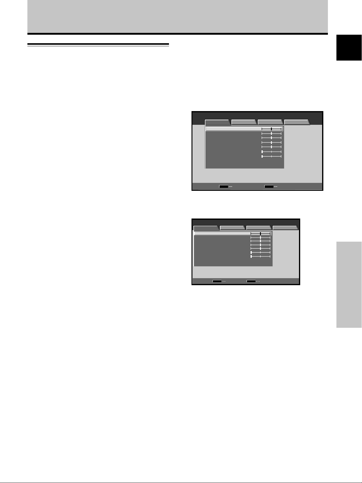
Regarding menu displays
The example menu displays provided in this manual are
those for the PDP-50MXE10/PDP-50MXE11/PDP50MXE1/PDP-50MXE1-S model. The PDP-43MXE1/PDP43MXE1-S display differs as shown:
Example of PDP-50MXE10/PDP-50MXE11/PDP50MXE1/PDP-50MXE1-S Menu Display:
MENU INPUT1
PICTURE SCREEN SETUP OPTION
ENTER
:
:
:
:
:
:
:
0
0
0
0
0
0
0
MENU
:
0
:
0
:
0
:
0
:
0
:
0
:
0
MENU
EXIT
CONTRAST
BRIGHTNESS
R.LEVEL
G.LEVEL
B.LEVEL
H.ENHANCE
V.ENHANCE
PICTURE RESET
SET
Example of PDP-43MXE1/PDP-43MXE1-S Menu
Display:
MENU INPUT1
PICTURE SCREEN SETUP OPTION
CONTRAST
BRIGHTNESS
R.LEVEL
G.LEVEL
B.LEVEL
H.ENHANCE
V.ENHANCE
PICTURE RESET
SET
ENTER EXIT
Please note that the actual contents displayed are the
same for both the PDP-50MXE10/PDP-50MXE11/
PDP-50MXE1/PDP-50MXE1-S and PDP-43MXE1/
PDP-43MXE1-S.
English
Before Proceeding
3
En
Page 8
Before Proceeding
About operations in this manual
English
Each operation is described in its proper operating order.
These Operating Instructions will refer to the operating
controls found on the remote control unit, with the
exception of those buttons found only on the main
plasma display itself. When the plasma display controls
include equivalent buttons to those found on the remote
control unit, the commands can be performed on the
main unit as well.
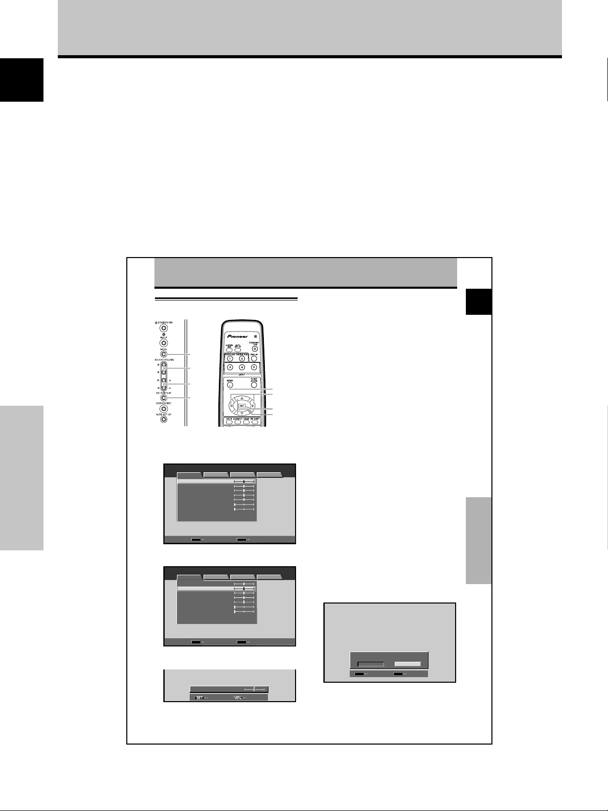
The following illustrations are an example of the actual
operations used for the section “PICTURE adjustment”.
The examples are provided to allow you to confirm
whether the operation is performed correctly or not.
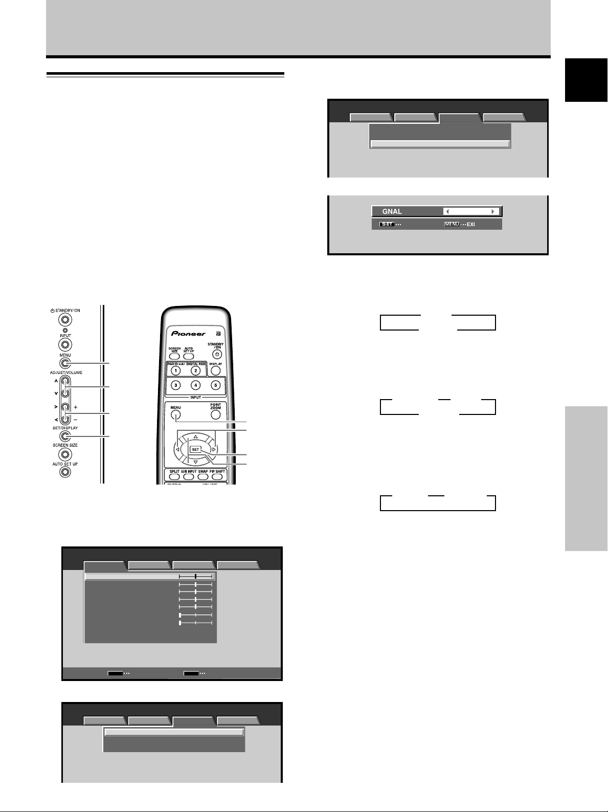
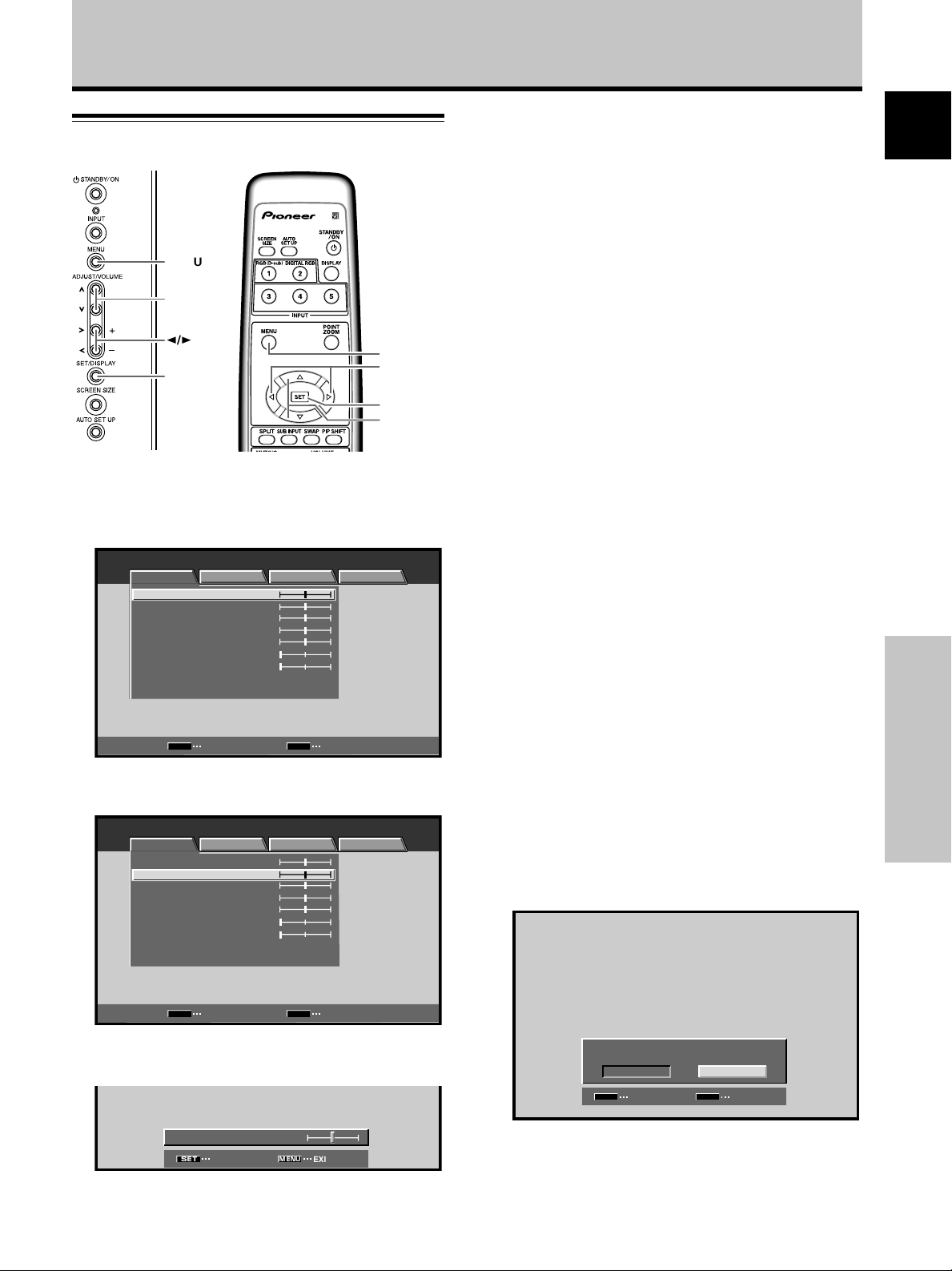
PICTURE/SCREEN Adjustment
PICTURE adjustment
MENU
5/∞
2/3
SET
Before Proceeding
Main unit operating
panel
1 Press the MENU button to display the menu
screen.
MENU INPUT1
PICTURE SCREEN SETUP OPTION
CONTRAST
BRIGHTNESS
R.LEVEL
G.LEVEL
B.LEVEL
H.ENHANCE
V.ENHANCE
PICTURE RESET
2 Use the 5/∞ buttons to select the adjustment
item, then press the SET button.
MENU INPUT1
PICTURE SCREEN SETUP OPTION
CONTRAST
BRIGHTNESS
R.LEVEL
G.LEVEL
B.LEVEL
H.ENHANCE
V.ENHANCE
PICTURE RESET
SET
ENTER
Remote control unit
:
:
:
:
:
:
:
:
:
:
:
:
:
:
Note
The screen images depicted in these Operating Instructions
should be considered typical images; some difference will be
seen in practice, depending on the screen item displayed and its
contents, the input source and various other control settings.
4 Press the SET button.
Pressing the SET button writes the value into the
memory and returns the display to the step 2 screen.
5 When the setup is finished, press the MENU
button to exit the menu screen.
Note
Make these adjustments for each input (INPUT1 or INPUT2) and
signals.
[PICTURE] mode adjustment items
MENU
2/3
SET
5/∞
0
0
0
0
0
0
0
MENU
EXIT
0
0
0
0
0
0
0
Below are brief descriptions of the options that can be set
in the [PICTURE] mode.
CONTRAST ············· Adjust according to the surrounding
BRIGHTNESS ·········· Adjust so that the dark parts of the
R. LEVEL ················· Adjust the amount of red in the
G. LEVEL ················· Adjust the amount of green in the
B. LEVEL ················· Adjust the amount of blue in the
H. ENHANCE··········· Sharpens the image in the horizontal
V. ENHANCE ··········· Sharpens the image in the vertical
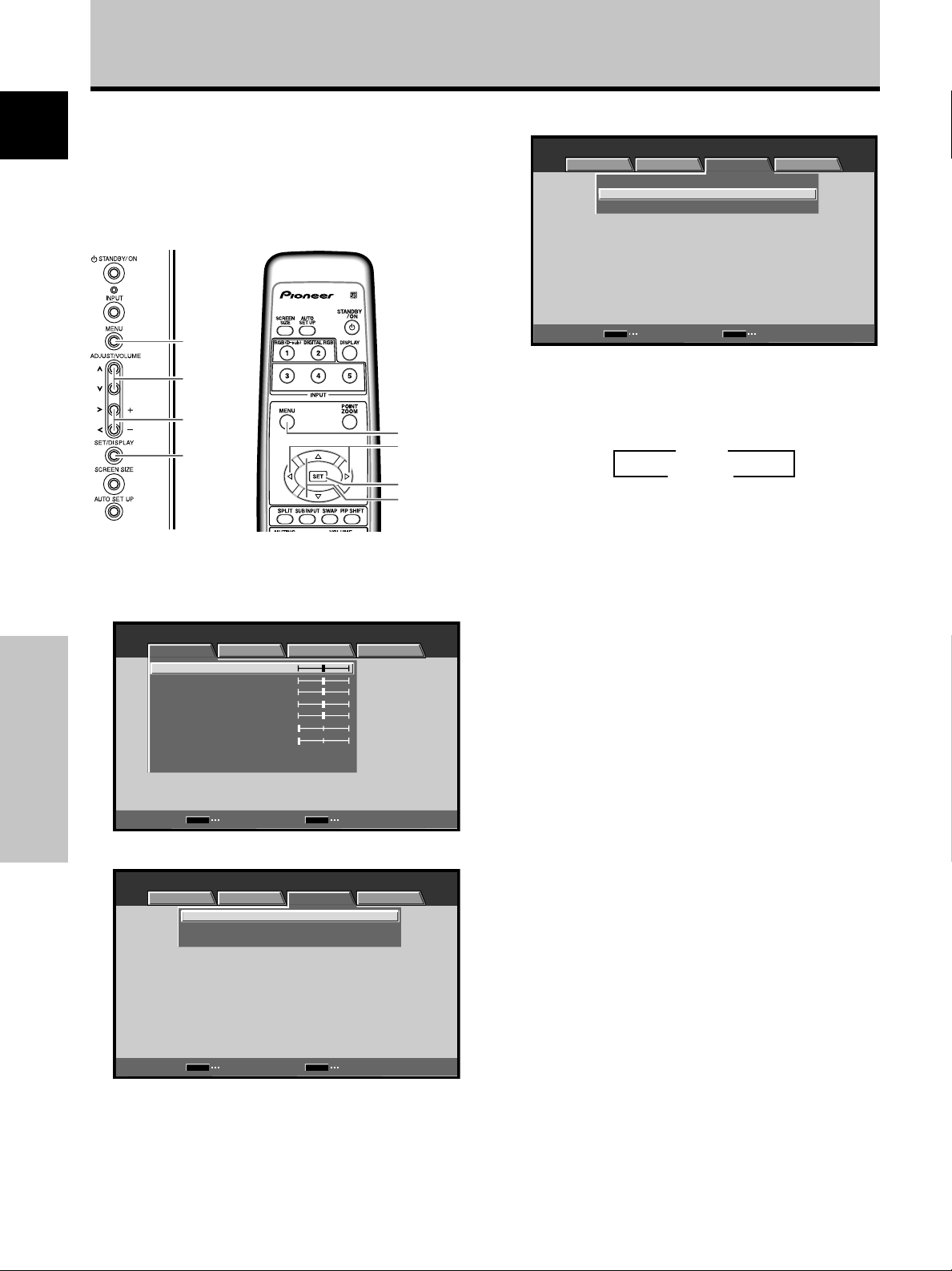
To reset [PICTURE] mode settings to the default
If settings have been adjusted excessively or the picture
on the screen no longer appears natural, it may prove
more beneficial to reset the [PICTURE] mode to default
settings instead of trying to make adjustments under
already adjusted conditions.
1 In step 2 in the previous procedure, use the 5/∞
buttons to select [PICTURE RESET], then press the
SET button.
brightness so that the picture can be
seen clearly.
picture can be seen clearly.
picture.
picture.
picture.
direction.
direction.
English
PICTURE/SCREEN Adjustment
SET
ENTER EXIT
3 Use the 2/3 buttons to adjust the picture quality
as desired.
BRIGHTNESS
MENU
:
SET EXIT
0
PICTURE RESET
YES
SET
SET
2 Use the 2/3 buttons to select [YES], and press
the SET button.
All [PICTURE] mode settings are returned to the
factory set default.
NO
MENU
EXIT
25
En
4
En
Page 9
Before Proceeding
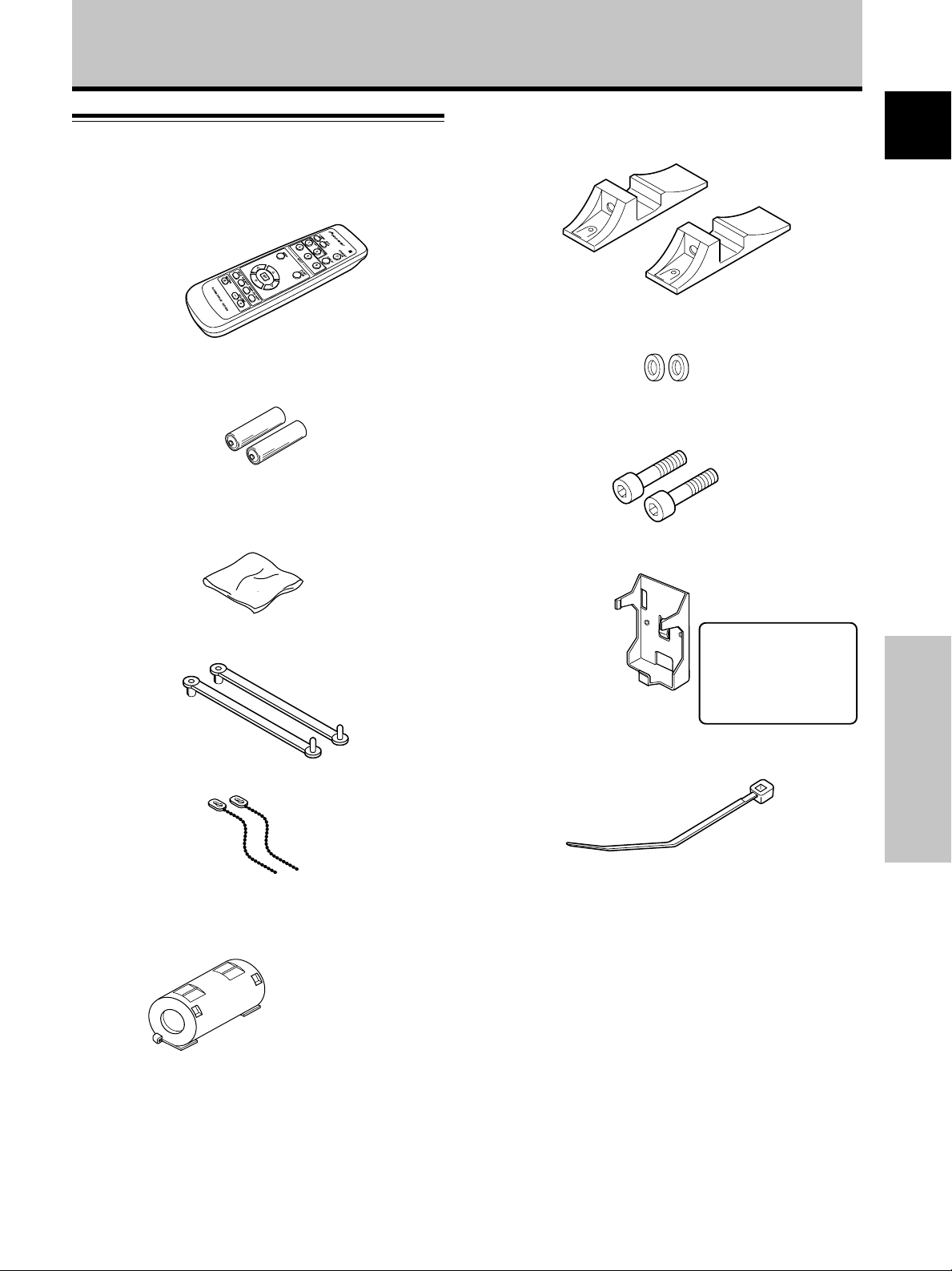
Checking supplied accessories
Check that the following accessories were supplied.
1 Remote control unit
2 AA (R6) batteries (x 2)
3 Cleaning cloth (for screen)
7 Display stands (x 2)
8 Washers (x 2)
9 Hex hole bolts (x 2)
0 Remote control unit holder
English
4 Speed clamps (x 2)
5 Bead bands (x 2)
6 Ferrite core
Use as a holder for the
remote control unit.
When attaching to the
rear of the main unit,
be careful not to cover
the vents.
- Cable tie
Before Proceeding
÷ These Operating Instructions
5
En
Page 10
Part Names and Functions
English
Main unit
Main unit
PDP-50MXE10/
PDP-50MXE11/
PDP-50MXE1/
PDP-50MXE1-S
345
1
6
PDP-43MXE1/
PDP-43MXE1-S
6
2
Operation panel on the main unit
7
8
9
0
-
=
~
!
Note
When optional speakers have been connected,
the operation panel on the main unit will not be
operable.
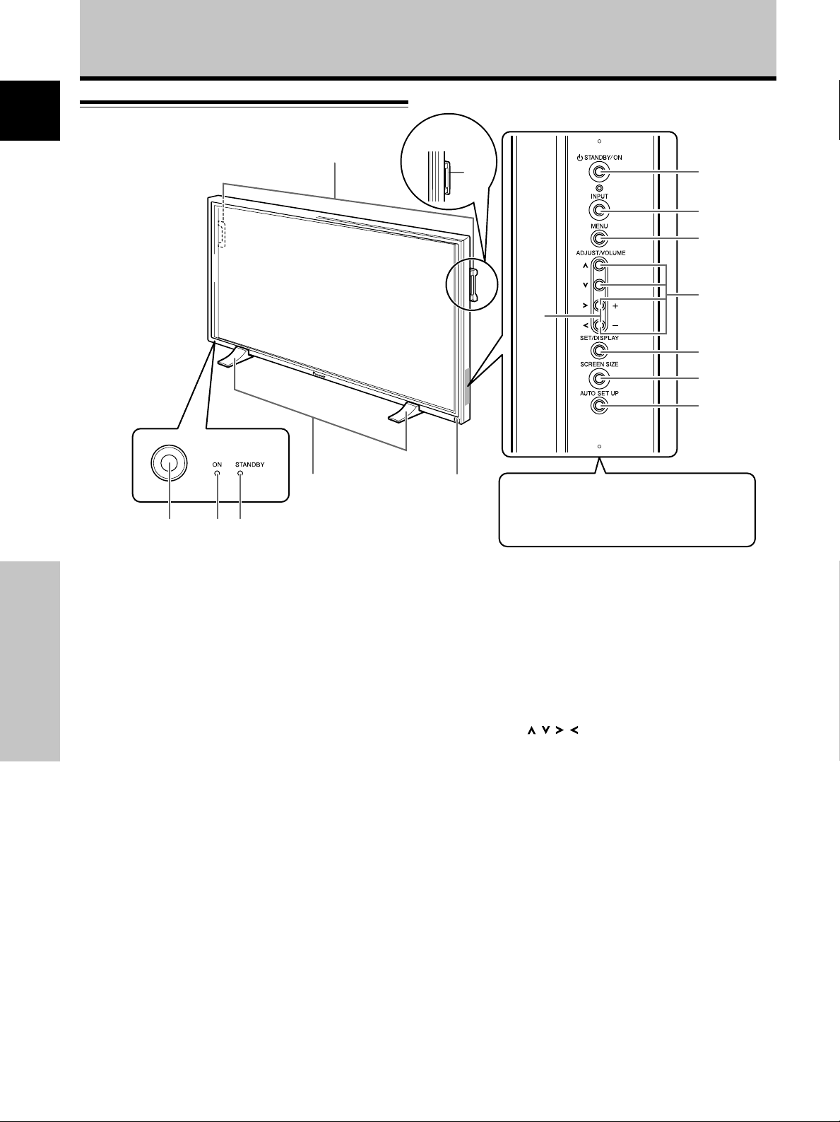
Main unit
1 Display stand
2 Remote control sensor
Point the remote control toward the remote sensor to
operate the unit (page 8).
3 Ambient light sensor
This sensor measures the level of light inside the
viewing room; it is enabled when the [ENERGY
Part Names and Functions
SAVE] option is set to [AUTO] (page 31).
4 ON indicator
Lights green when the plasma display is operating
(page 19).
When flashing, the indicator is used to indicate error
messages (page 36).
The indicator flashes green once every one second
when the [POWER MANAGEMENT] function is
operating (page 24).
5 STANDBY indicator
Lights red when the unit is in standby mode (page 19).
When flashing, the indicator is used to indicate error
messages (page 36).
6 Handles
The plasma displays PDP-50MXE10/PDP-50MXE11/
PDP-50MXE1/PDP-50MXE1-S and PDP-43MXE1/PDP43MXE1-S utilize differing methods of handle
attachment, but the handles themselves are used in the
same way (page 11).
6
En
Operation panel on the main unit
7 STANDBY/ON button
Press to put the display in operation or standby mode
(page 19).
8 INPUT button
Press to select the input (page 19).
9 MENU button
Press to open and close the on-screen menu (pages
16 to 33).
0 ADJUST ( / / / ) buttons
Use these buttons to move the onscreen cursor
between selection options, and to perform
adjustments. Instructions for use are given with each
command option onscreen (pages 16 to 33).
- VOLUME (+/–) buttons
When not indicated for use in onscreen menu items,
these buttons are used for adjusting the sound
volume (pages 19 and 20).
= SET/DISPLAY button
Use to confirm onscreen menu selections, and to
change settings (pages 16 to 33).
When not indicated by onscreen menus, used to
display the current set status (page 20).
~ SCREEN SIZE button
Press to select the screen size (page 21).
! AUTO SET UP button
When using computer signal input, automatically sets
the [POSITION], [CLOCK] and [PHASE] to optimum
values (page 26).
Page 11
Remote control unit
1
2
3
4
9
0
-
=
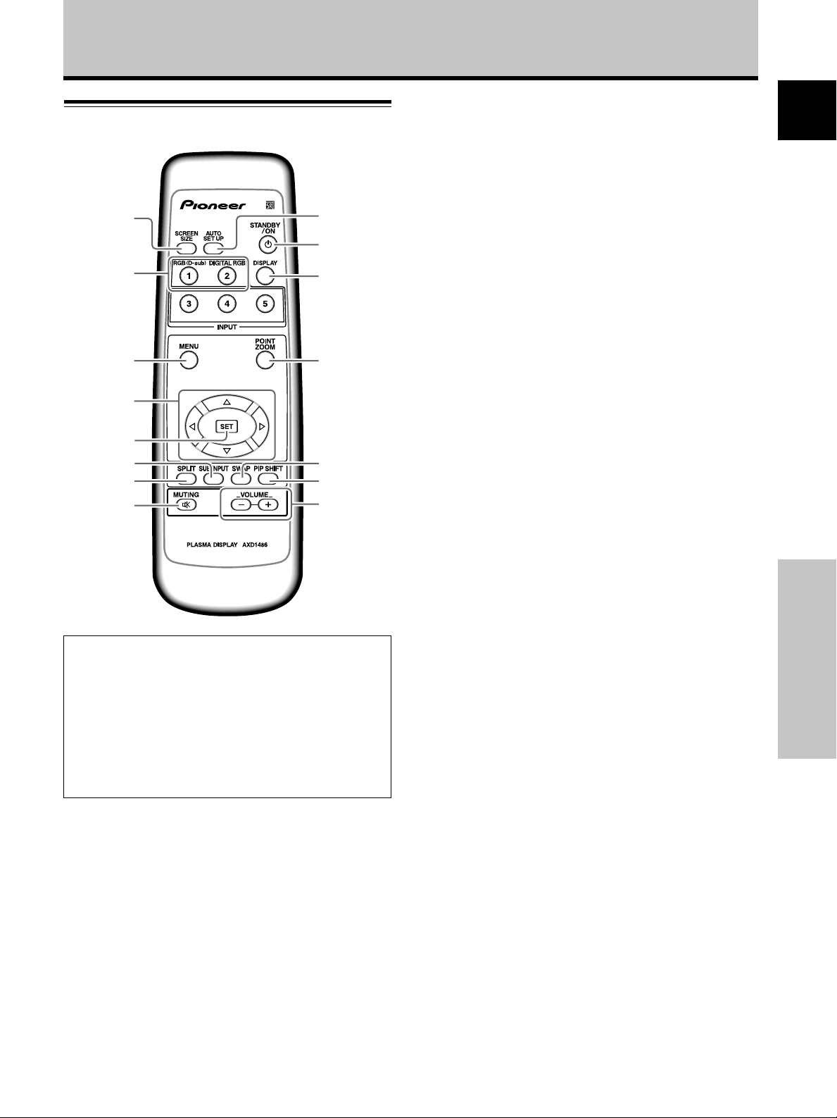
Part Names and Functions
1 SCREEN SIZE button
Press to select the screen size (page 21).
2 INPUT buttons
Press to select the input (page 19).
3 MENU button
Press to open and close the on-screen menu
(pages 16 to 33).
4 ADJUST (5/∞/3/2) buttons
Use to navigate menu screens and to adjust various
settings on the unit (pages 16 to 33).
5 SET button
Press to adjust or enter various settings on the unit
(pages 16 to 33).
6 SUB INPUT button
During multi-screen display, use this button to change
inputs to subscreens (page 23).
English
5
6
7
8
When handling the remote control unit
¶ Do not drop the remote control unit or expose it to
moisture.
¶ Do not use the remote control unit in a location subject to
direct sunlight, heat radiation from a heater, or in a place
subject to excessive humidity.
¶ When the remote control unit’s batteries begin to wear out,
the operable distance will gradually become shorter. When
this occurs, replace all batteries with new ones as soon as
possible.
~
!
@
7 SPLIT button
Press to switch to multi-screen display (page 23).
8 MUTING button
Press to mute the volume (page 20).
9 AUTO SET UP button
When using computer signal input, automatically sets
the [POSITION], [CLOCK] and [PHASE] to optimum
values (page 26).
0 STANDBY/ON button
Press to put the unit in operation or standby mode
(page 19).
- DISPLAY button
Press to view the unit’s current input and setup mode
(page 20).
Part Names and Functions
= POINT ZOOM button
Use to select and enlarge one part of the screen (page
22).
~ SWAP button
During multi-screen display, use this button to switch
between main screen and subscreen (page 23).
! PIP SHIFT button
When using PinP mode with multi-screen display, use
this button to move the position of subscreen (page
23).
@ VOLUME (+/–) buttons
Use to adjust the volume (pages 19 and 20).
7
En
Page 12
Part Names and Functions
English
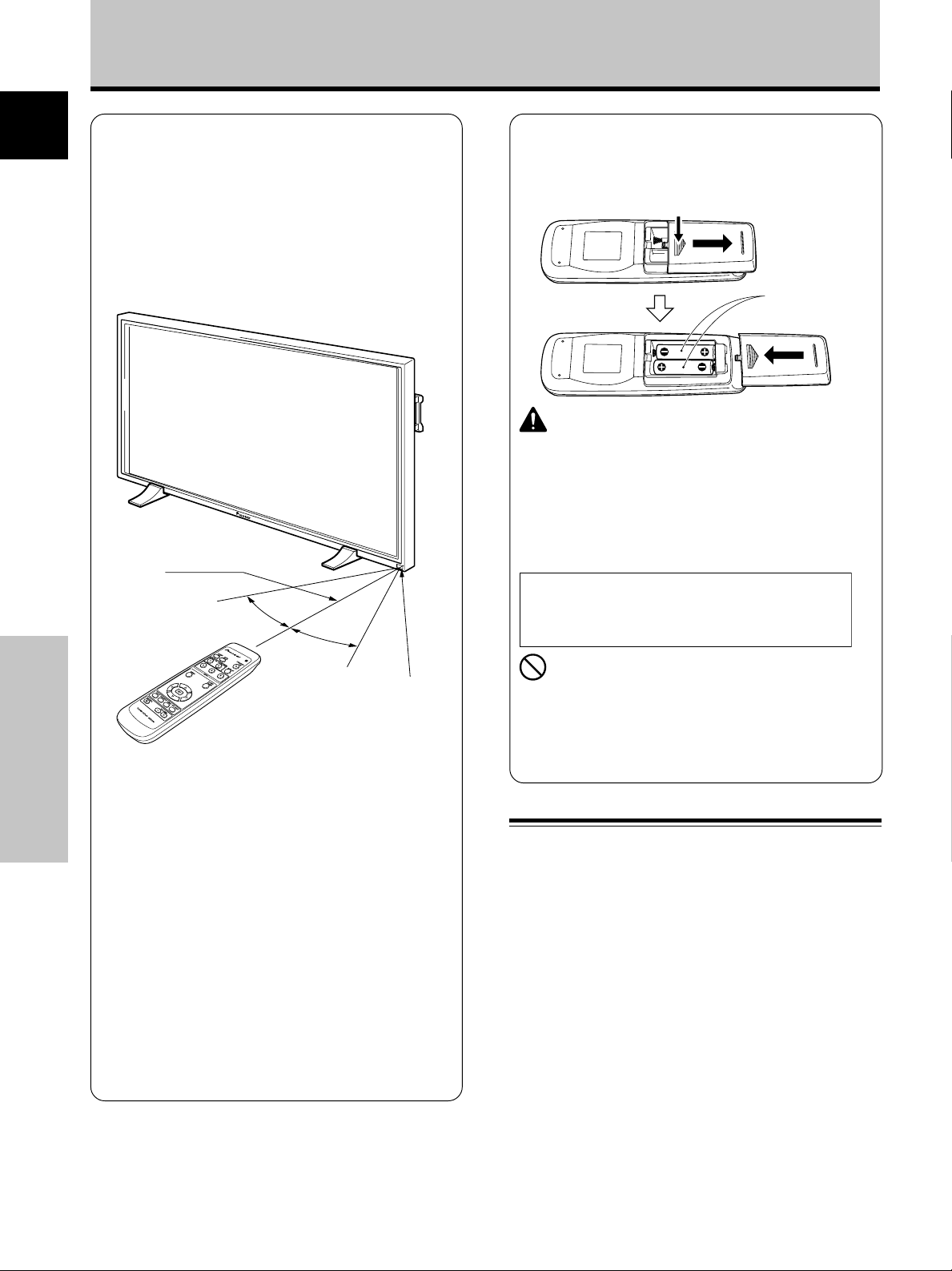
Operating range of the remote
control unit
When operating the remote control unit, point it at the
remote sensor (Î) located on the front panel of the
main unit. The remote control unit is operable up to 7 m
from the unit and within a 30 angle on each side of the
sensor.
7 m
If you are having difficulty with operation of
the remote control unit
Part Names and Functions
¶ The remote control unit may not operate if there are
objects placed between it and the display.
¶ Operational distance will gradually become shorter as the
batteries begin to wear out, replace weak batteries with
new ones as soon as possible.
¶ This unit discharges infrared rays from the screen. Placing a
video deck or other component that is operated by an
infrared remote control unit near this unit may hamper that
component’s reception of the remote control’s signal, or
prevent it from receiving the signal entirely. Should this
occur, move the component to a position further away from
this unit.
¶ Depending on the installation surroundings, this unit’s
remote control unit may be influenced by the infrared rays
discharged from the plasma display, hampering reception of
its rays or limiting its operational distance. The strength of
infrared rays discharged from the screen will differ
according to the picture displayed.
30°
30°
Remote Sensor
Inserting the batteries in the
remote control unit
While pressing down lightly, slide
in the direction of the arrow.
Two AA (R6)
batteries
CAUTION
¶ Insert batteries so that the plus (+) and minus (–) sides
are aligned according to the markings in the battery case.
¶ When not using the remote control unit for a long period
of time (1 month or more), remove the batteries from the
remote control unit to prevent leaking of battery fluid. If
battery liquid has leaked, thoroughly wipe the inside of
the case until all liquid is removed, and then insert new
batteries.
When disposing of used batteries, please comply
with governmental regulations or
environmental public instruction’s rules that
apply in your country/area.
D3-4-2-3-1_En
NO!
¶ Do not mix new batteries with used ones.
¶ The voltage of batteries may differ even if they are the
same shape. Please do not mix different kinds of
batteries together.
¶ Do not charge, short, disassemble or throw the provided
batteries in a fire.
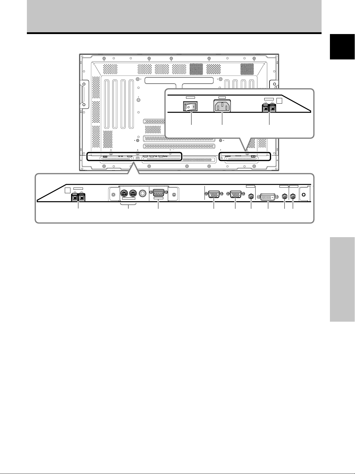
Connection panel
The connection panel is provided with two video input
terminals and one video output terminal. Audio input/
output and speaker output terminals are also provided.
For instructions regarding connections, consult the pages
noted in parentheses by each item.
1 SPEAKER (R) terminal
For connection of an external right speaker.
Connect a speaker that has an impedance of 8 -16 Ω
(page 13).
2 COMBINATION IN/OUT
Never connect any component to these
connectors without first consulting your Pioneer
installation technician.
These connectors are used for plasma display setup
adjustments.
8
En
Page 13
Part Names and Functions
Illustration depicts PDP-50MXE10/PDP-50MXE11/PDP-50MXE1/PDP-50MXE1-S model.
POWER
ON
OFF
AC IN
SPEAKER
8Ω ~16Ω
+ –
=-0
SPEAKER
8Ω ~16Ω
R
+ –
1
IN OUT
COMBINATION
RS-232C
23
ANALOG RGB IN
ANALOG RGB OUT
D-Sub
4 5 6
INPUT1 INPUT2 OUTPUT
D-Sub
DIGITAL RGB
AUDIO AUDIO AUDIO
DVI-D
7 8 9
English
L
3 RS-232C
Never connect any component to this connector
without first consulting your Pioneer installation
technician.
This connector is used for plasma display setup
adjustments.
4 ANALOG RGB IN (INPUT1) (mini D-sub 15 pin)
For connection of a personal computer (PC) or similar
component. Make sure that the connection made
corresponds to the format of the signal output from
the connected component (page 12).
5 ANALOG RGB OUT (INPUT1) (mini D-sub 15 pin)
Use the ANALOG RGB OUT (INPUT1) terminal to
output the video signal to an external monitor or other
component.
Note: The video signal will not be output from the
ANALOG RGB OUT (INPUT1) terminal when the main
power of this unit is off or in standby mode.
(page 12)
6 AUDIO (INPUT1) (Stereo mini jack)
Use to obtain sound when INPUT1 is selected.
Connect the audio output jack of components
connected to INPUT1 to this unit (page 13).
8 AUDIO (INPUT2) (Stereo mini jack)
Use to obtain sound when INPUT2 is selected.
Connect the audio output jack of components
connected to INPUT2 to this unit (page 13).
9 AUDIO (OUTPUT) (Stereo mini jack)
Use to output the audio of the selected source
component connected to this unit to an AV amplifier
or similar component.
Note: No sound is produced from the AUDIO (OUTPUT) jack
when the MAIN POWER switch is set to OFF or ON (standby)
(page 13).
0 MAIN POWER switch
Use to switch the main power of the unit on and off.
- AC IN
Use to connect a power cord to an AC outlet (page
14).
= SPEAKER (L) terminal
For connection of an external left speaker. Connect a
speaker that has an impedance of 8 -16 Ω (page 13).
Part Names and Functions
7 DIGITAL RGB (INPUT2) (DVI-D jack)
Use to connect a computer.
Note: This unit does not support the display of
copyguard-protected video signals (page 12).
9
En
Page 14
Installation and Connections
English
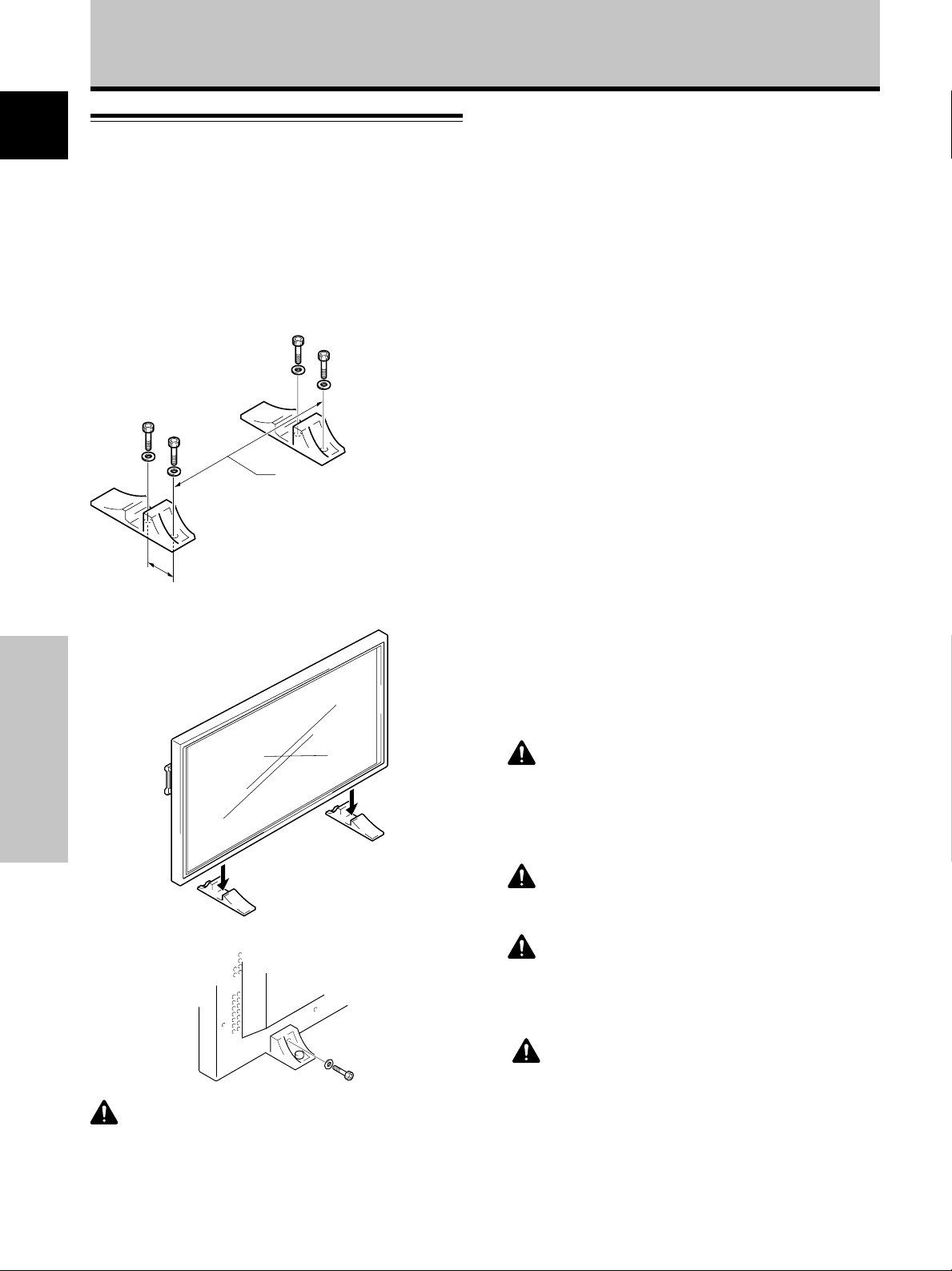
Installation of the unit
Installation using the supplied display stands
Be sure to fix the supplied stands to the installation surface.
Use commercially available M8 bolts that are 25 mm
longer than the thickness of the installation surface.
1 Fix the supplied stands to the installation surface
at each of the 4 prepared holes using
commercially available M8 bolts.
Front
PDP-50MXE10/PDP-50MXE11/
PDP-50MXE1/PDP-50MXE1-S:
798 mm (Bolt hole thread pitch)
Rear
Always install the supplied display stands
according to the dimensions shown in
110 mm
the accompanying illustration.
2 Set this unit in the stands.
PDP-43MXE1/PDP-43MXE1-S:
880 mm (Bolt hole thread pitch)
Installation using the optional PIONEER stand or
installation bracket
÷ Please be sure to request installation or mounting of this unit
or the installation bracket by an installation specialist or the
dealer where purchased.
÷ When installing, be sure to use the bolts provided with the
stand or installation bracket.
÷ For details concerning installation, please refer to the
instruction manual provided with the stand or installation
bracket.
Installation using accessories other than the
PIONEER stand or installation bracket (sold
separately)
÷ When possible, please install using parts and accessories
manufactured by PIONEER. PIONEER will not be held
responsible for accident or damage caused by the use of parts
and accessories manufactured by other companies.
÷ For custom installation, please consult the dealer where the
unit was purchased, or a qualified installer.
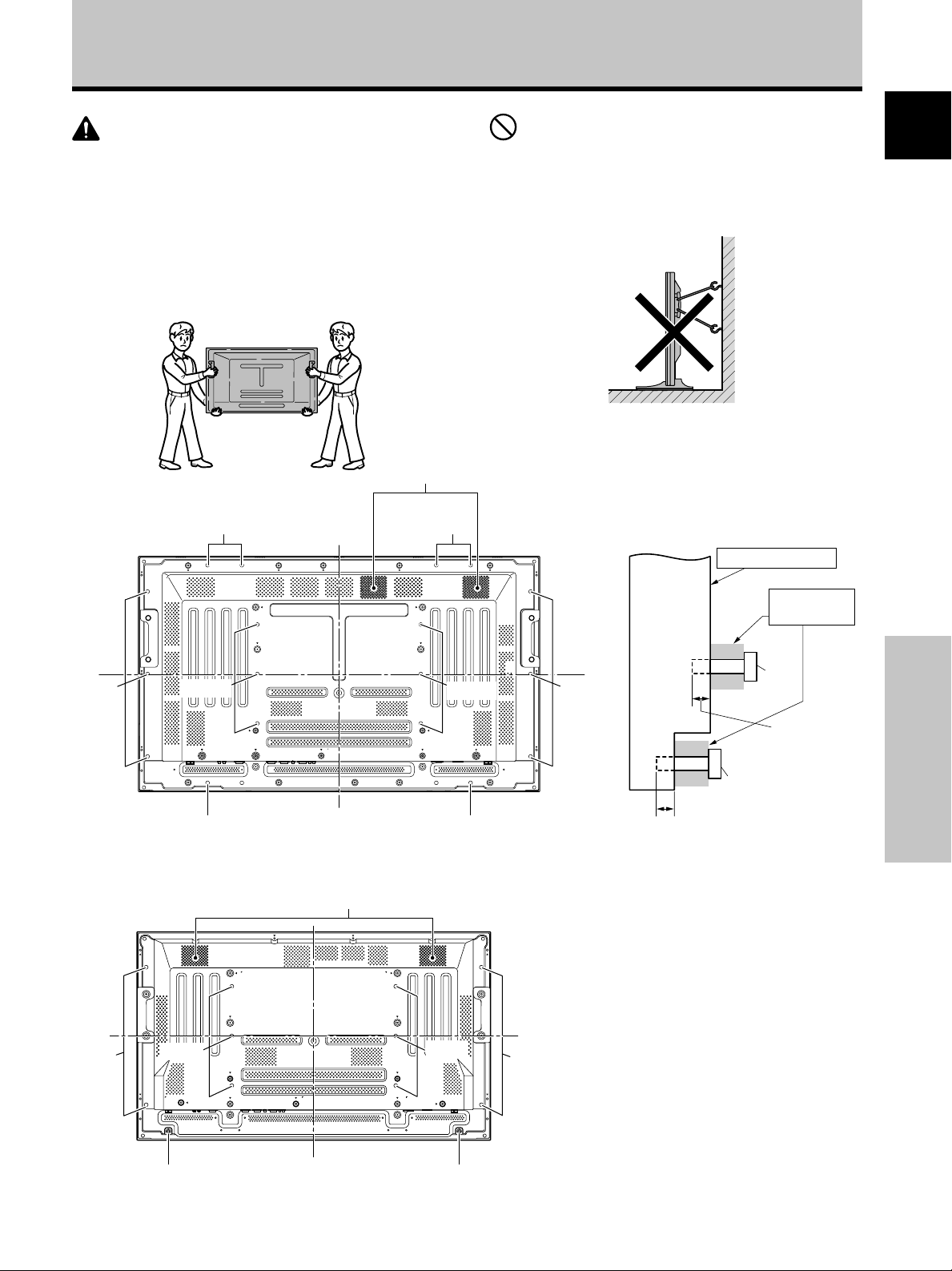
Wall-mount installation of the unit
This unit has been designed with bolt holes for
wall-mount installation, etc. The installation holes
provided are shown in the accompanying illustration.
÷ Be sure to attach in 4 or more locations above and
below, left and right of the center line.
÷ Use bolts that are long enough to be inserted 12 mm to
18 mm into the main unit from the attaching surface for
both a holes and b holes. Refer to the side view
diagram in the accompanying illustration.
÷ As this unit is constructed with glass, be sure to install
it on a flat, unwarped surface.
Installation and Connections
3 Fix this unit using the supplied washer and bolt.
Use a 6 mm hex wrench
CAUTION
This display unit weighs at least 30 kg and has little front-to-back
depth, making it very unstable when stood on edge. As a result,
two or more persons should cooperate when unpacking, moving,
or installing the display.
to bolt them.
10
En
CAUTION
To avoid malfunction, overheating of this unit, and possible fire
hazard, make sure that the vents on the main unit are not
blocked when installing. Also, as hot air is expelled from the air
vents, be careful of deterioration and dirt build up on rear surface
wall, etc..
CAUTION
Please be sure to use an M8 (Pitch = 1.25 mm) bolt. (Only this
size bolt can be used.)
CAUTION
This display unit weighs at least 30 kg and has little front-to-back
depth, making it very unstable when stood on edge. As a result,
two or more persons should cooperate when unpacking, moving,
or installing the display.
CAUTION
This unit incorporates a thin design. To ensure safety if vibrated
or shaken, please be sure to take measures to prevent the unit
from tipping over.
Page 15
Installation and Connections
CAUTION
÷ Handles should not be removed or reattached by anyone other
than the professional installation technician or service
personnel.
÷ If handles must be removed due to specific installation
conditions, the mounting screws should be stored carefully
together with the handles. To ensure safety, the mounting
screws should be tightened to a minimum torque of 2N·m (20
kgf·cm) when reattaching the handles.
÷ When moving the display, it should always be carried by two
persons holding the rear handles in the manner shown.
Air vents (fan)
b hole
b hole
a hole
b hole
a hole
NO!
÷ Never attempt to move the plasma display by holding only one
of the handles.
÷ When installing the plasma display, do not use the handles as
means of hanging the display; also do not use them as devices
to prevent tipping over (see illustration).
Attaching surface
Installation
bracket, etc..
Main unit
Center line
b hole
a hole
Bolt
English
Français
b hole
Center line
b holeb hole
Rear view diagram (PDP-50MXE10/PDP-50MXE11/
PDP-50MXE1/PDP-50MXE1-S)
Air vents (fan)
Center line
a hole
Center line
a hole
b holeb hole
b hole
Rear view diagram (PDP-43MXE1/PDP-43MXE1-S)
b hole
12 mm to 18 mm
Side view diagram
12 mm to 18 mm
Bolt
Installation and Connections
11
En
Page 16
Installation and Connections
English
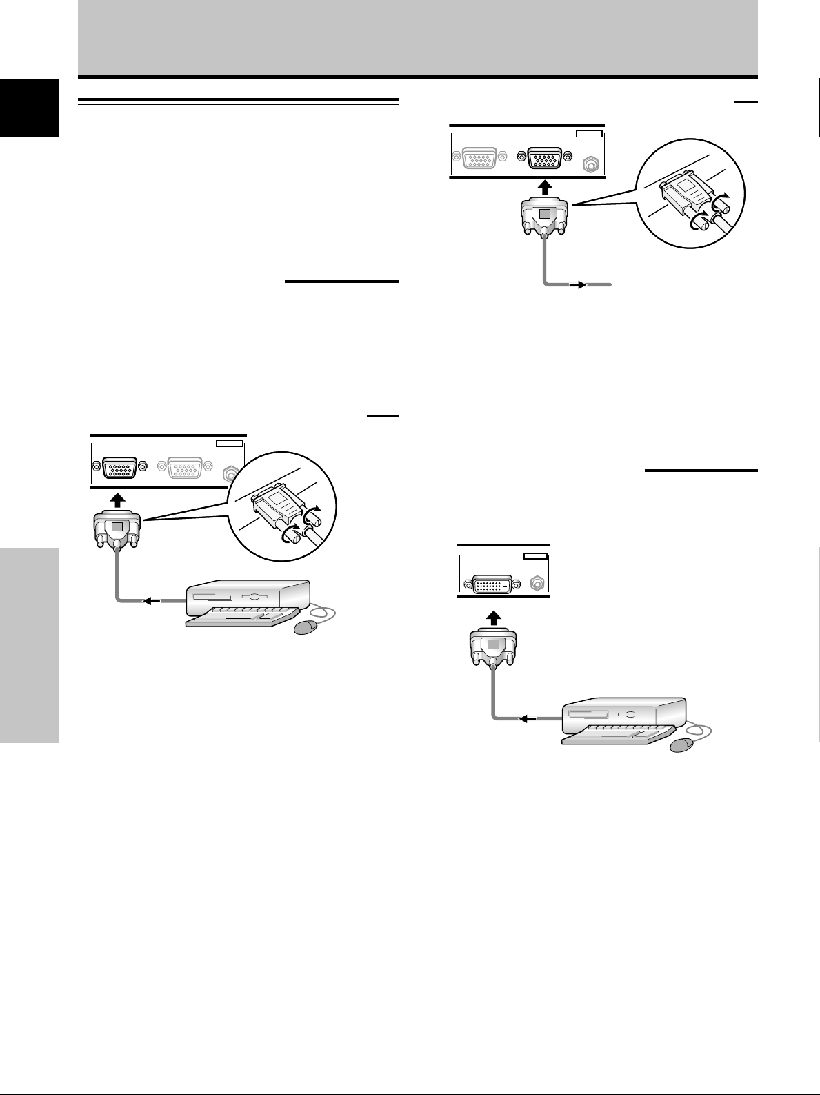
Connection to a personal computer
Connection method differs depending on the computer
type. When connecting, please thoroughly read the
computer’s instruction manual.
Before making connections, be sure to make sure that
the personal computer’s power and this unit’s main
power is off.
When connecting to ANALOG RGB OUT (INPUT1)
ANALOG RGB IN
D-Sub
ANALOG RGB OUT
D-Sub
INPUT1
AUDIO
Connection to INPUT1
Connect the display’s D-sub input connector to the D-sub
output (analog RGB) from the computer.
This connector also supports G ON SYNC (output with
green signal combined with sync signal), and composite
SYNC (output with combined horizontal and vertical sync
signals).
When connecting to ANALOG RGB IN (INPUT1)
ANALOG RGB IN
D-Sub
ANALOG RGB OUT
D-Sub
Connect the cable corresponding to the shape of the
input terminal on this unit and the personal computer’s
output terminal.
Installation and Connections
Secure by tightening the terminal screws on both units.
INPUT1
AUDIO
To an external monitor
With this unit, it is possible to output the video signal to
an external monitor or other component from the
ANALOG RGB OUT (INPUT1) terminal.
Note
A video signal will not be output from the ANALOG RGB OUT
(INPUT1) terminal when the main power of this unit is off or in
standby.
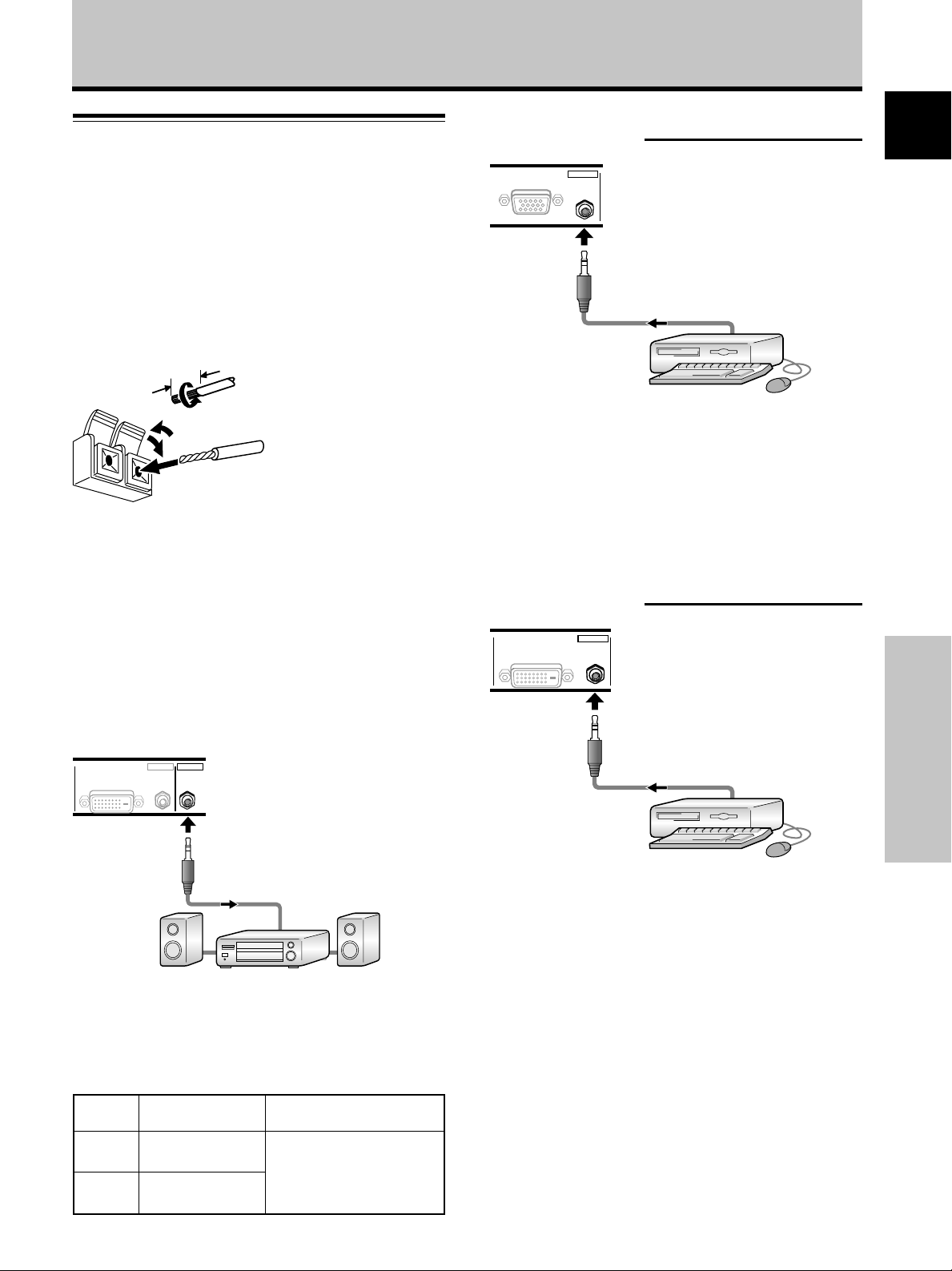
Connection to INPUT2
A computer equipped with DVI output (digital RGB signal)
can be connected to the video card’s DVI connector.
DVI-D
INPUT2
AUDIO
DIGITAL RGB
Following completing connections, on-screen setup is
necessary. See pages 16 to 18 for details.
Note
Depending on the type of computer model being connected, a
conversion connector or adapter etc. provided with the computer
or sold separately may be necessary.
For details, please read your PC’s instruction manual or consult
the maker or nearest dealer of your computer.
NOTICE
¶ INPUT1 supports Microsoft “Plug & Play” (VESA DDC 1/2B)
components. See Appendix 2-1/2 (page 42) when making
connections to INPUT1.
¶ See Appendix 1 (pages 38 and 40) for information regarding
signals and display formats supported by INPUT1.
12
En
Following completing connections, on-screen setup is
necessary. See pages 16 to 18 for details.
Notes
¶ Use a DVI-D 24-pin (digital only) cable for the connection.
¶ This unit does not support the display of copyguard-protected
video signals.
NOTICE
¶ INPUT2 supports Microsoft “Plug & Play” (VESA DDC 2B)
components. See Appendix 2-2/2 (page 42) when making
connections to INPUT2.
¶ See Appendix 1 (pages 39 and 41) for information regarding
signals and display formats supported by INPUT2.
Page 17
Audio connections
Installation and Connections
Audio connections for component (computer)
connected to INPUT1
English
Before making connections, be sure to check that the
audio component’s power and the unit’s main power is
off.
Connecting the speakers
This unit is equipped with speaker output terminals for
connection to the speaker system (not supplied) specially
designed for use with this unit. Refer to the illustrations
below when making connections to the speaker terminals
on this unit.
12 mm
Twist exposed
wire strands
together.
Push tab to the open
position, and insert the
wire. Then, close tab
firmly to secure the wire
in place.
Notes
÷ After connecting the wires, pull gently on the cables to confirm
that the wire cores are fastened securely in their terminals.
Insecure connections will result in noise or interrupted sound.
÷ Do not allow the wire cores of the ª and · speaker cables to
protrude excessively, since they may touch each other,
causing a short circuit. This will produce excessive load on the
plasma display, causing operation to malfunction or stop.
Connection to audio output connector
Use a stereo miniplug to connect the plasma display’s
AUDIO (OUTPUT) stereo mini jack (L/R) to an AV amplifier
or other component.
ANALOG RGB OUT
D-Sub
INPUT1
AUDIO
A stereo miniplug cable can be used to connect the audio
output from the component connected to INPUT1, to the
plasma display’s AUDIO (INPUT1) stereo mini jack (L/R).
Sound is output from both the AUDIO (OUTPUT) stereo
mini jack (L/R) and the SPEAKER (L/R) terminals according
to the video input selection.
Audio connections for component (computer)
connected to INPUT2
DIGITAL RGB
DVI-D
INPUT2
AUDIO
Français
OUTPUT
DVI-D
INPUT2
AUDIO AUDIO
DIGITAL RGB
Making connections to the audio inputs on this
unit
This unit features two audio inputs and one audio output.
The following chart shows the video inputs and the
corresponding audio input terminals.
Video
input
INPUT1
INPUT2
Audio input jacks Sound output
Stereo mini jack
(L/R)
Stereo mini jack
(L/R)
Sound of the selected video
input is output from the
• SPEAKER (L/R) terminals
• Stereo mini jack (L/R)
Installation and Connections
A stereo miniplug cable can be used to connect the audio
output from the component connected to INPUT2, to the
plasma display’s AUDIO (INPUT2) stereo mini jack (L/R).
Sound is output from both the AUDIO (OUTPUT) stereo
mini jack (L/R) and the SPEAKER (L/R) terminals according
to the video input selection.
13
En
Page 18
Installation and Connections
English
Power cord connection
Connect a power cord after all component connections
have been completed.
PDP-50MXE10/PDP-50MXE11/PDP-50MXE1/
PDP-50MXE1-S/PDP-43MXE1/PDP-43MXE1-S power
cord ratings
Cord .......................... Cross-sectional area 3 x 1.0 mm
(According to CEE 13)
Connector ................................................... 10 A, 250 V
(According to EN60320 Sheet C13)
Plug ................................ International use (10 A, 250 V)
Example:
UK : UK 13 Amp Plug with rated 13 Amp fuse
(According to BS1363)
EURO : 10 A/16 A 250 V (According to CEE 7, 1 V)
CAUTION
For the plasma display, a three-core power cord with a ground
terminal is used for efficiency protection.
Always be sure to connect the power cord to a three-pronged
grounded outlet and make sure that the cord is properly
grounded. If you use a power source converter plug, use an
outlet with a ground terminal and screw down the ground line.
2
NO!
Do not use a power supply voltage other than that indicated (AC
100 - 240 V, 50/60 Hz) as this may cause fire or electric shock.
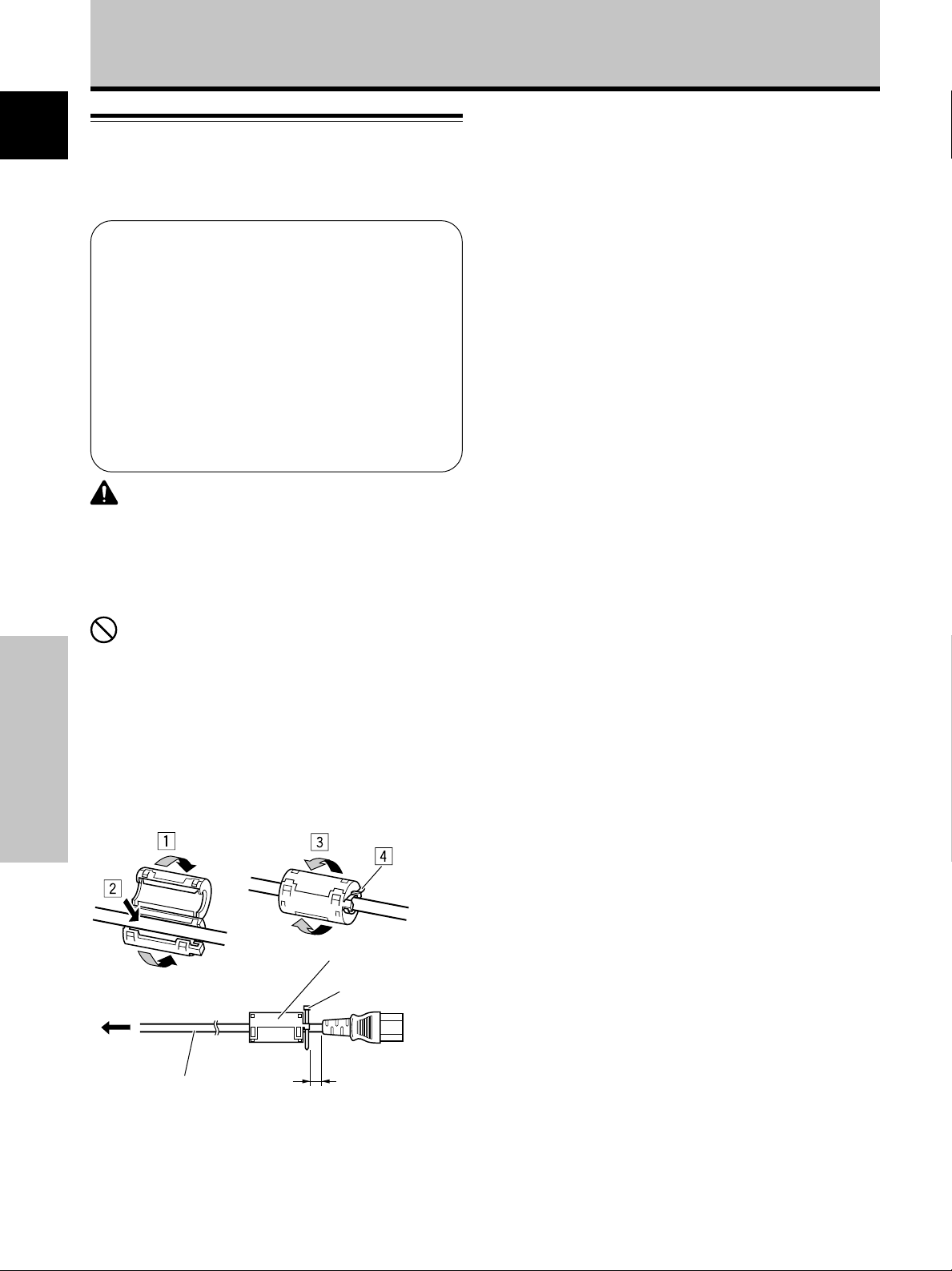
Attaching the ferrite core
To help prevent noise, attach the accessory ferrite core to
the connector end of the power cord as shown in the
accompanying illustration. Use the provided cable tie to
prevent the ferrite core from slipping on the cable.
Installation and Connections
Ferrite core
Cable tie
To power
outlet
AC power cord
As close as possible
To AC IN
14
En
Page 19
Installation and Connections
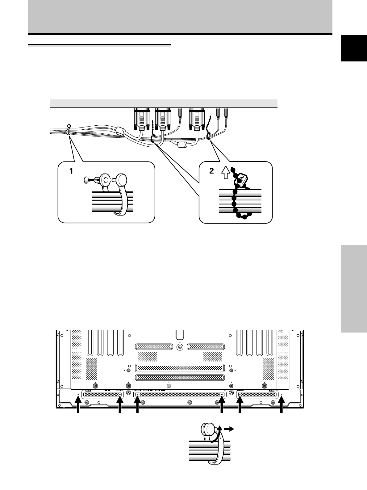
How to route cables
Speed clamps and bead bands are included with this unit
for bunching cables together. Once components are
connected, follow the following steps to route cables.
2
1
English
* As viewed from the rear of the display.
Français
1 Organize cables together using the provided
speed clamps.
Insert 1 into an appropriate hole on the rear of the
unit, then snap 2 into the back of 1 to fix the clamp.
Speed clamps are designed to be difficult to undo
once in place. Please attach carefully.
To attach the speed clamps to the main unit
Connect the speed clamps using the 6 holes marked with
“‡” below, depending on the situation.
2 Bunch separated cables together and secure them
with the provided bead bands.
Do not allow excessive stress to be placed on the
ends of cables.
Note
Cables can be routed to the right or left.
Illustration depicts PDP-50MXE10/PDP-50MXE11/
PDP-50MXE1/PDP-50MXE1-S model.
* As viewed from the rear of the display.
Installation and Connections
To remove speed clamps
Using pliers, twist the clamp 90° and pull it outward.
In some cases the clamp may have deteriorated over
time and may get damaged when removed.
15
En
Page 20
System Settings
English
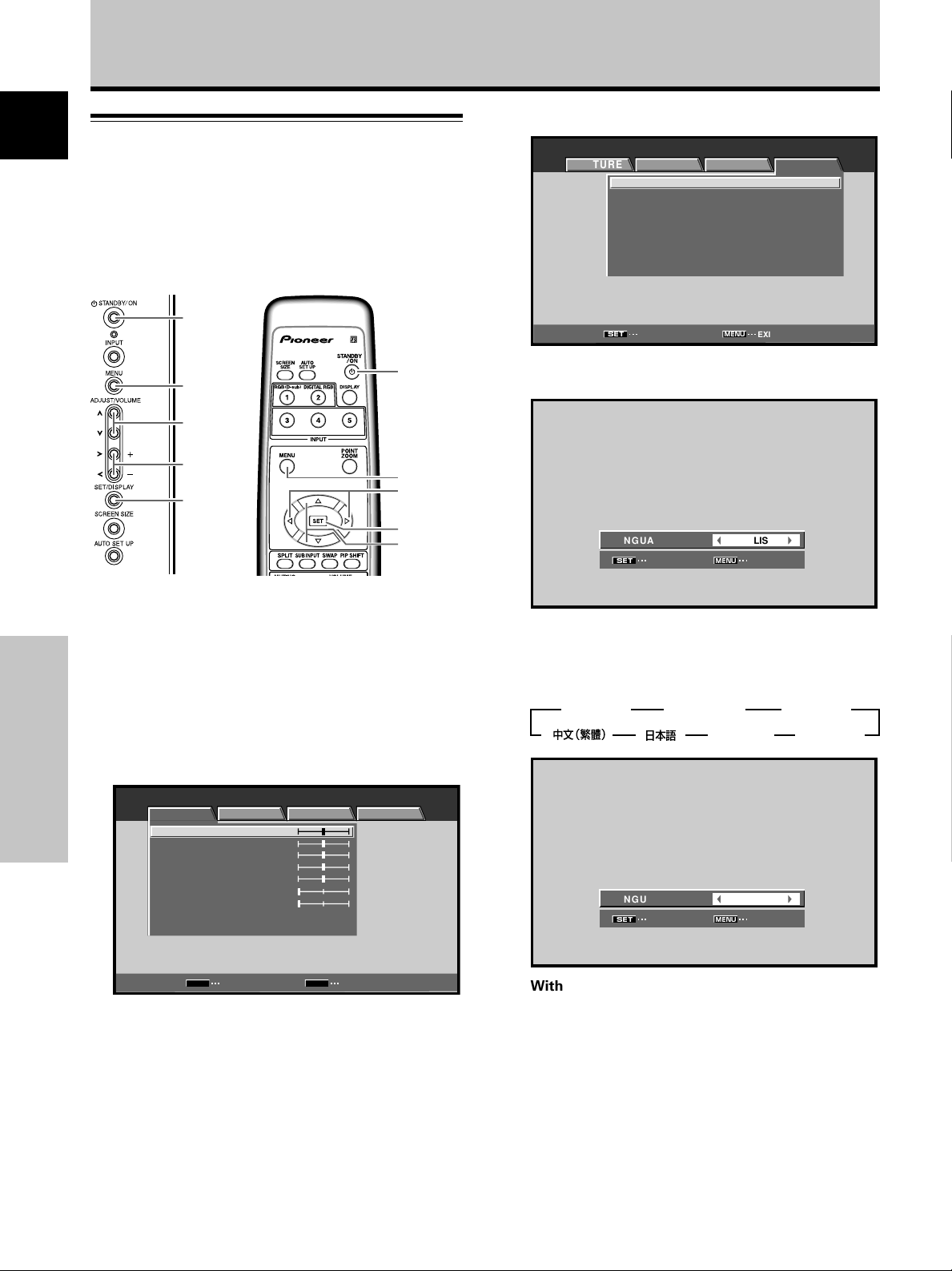
Setting the onscreen display
language
The onscreen display language has been set to English as
the factory default. To change to another language, the
screen setting must be changed. Follow the procedures
below to change the setting.
STANDBY/
ON
4 Use the 2/3 buttons to select [OPTION].
MENU INPUT1
PICTURE SCREEN SETUP OPTION
MENU
:
:
STANDARD
:
OFF
:
:
:
:
:
EXIT
LANGUAGE ENGLISH
ENERGY SAVE
SCREEN MGT.
ORBITER OFF
MASK CONTROL ON
AUTO SET UP MODE INACTIVE
AUTO FUNCTION OFF
AUDIO OUT FIXED
SET
ENTER
MENU
5/∞
2/3
SET
Main unit operating
Remote control unit
panel
1 Set the rear panel MAIN POWER switch to ON.
The STANDBY indicator on the front panel will light
red.
2 Press the STANDBY/ON button to turn the power
ON.
The ON indicator on the front panel will light green.
3 Press the MENU button to display the menu
screen.
System Settings
MENU INPUT1
PICTURE SCREEN SETUP OPTION
CONTRAST
BRIGHTNESS
R.LEVEL
G.LEVEL
B.LEVEL
H.ENHANCE
V.ENHANCE
PICTURE RESET
:
0
:
0
:
0
:
0
:
0
:
0
:
0
STANDBY/
ON
MENU
2/3
SET
5/∞
5 Use the 5/∞ buttons to select [LANGUAGE], then
press the SET button.
3
FRANÇAIS
:
MENU
3
ITALIANO
:
MENU
ENGLISH
EXIT
2 3
23 2
ENGLISH
EXIT
ESPAÑOL
DEUTSCH
2
2
LANGUAGE
SET
SET
6
Use the 2/3 buttons to select the desired language.
Each time the 2/3 buttons are pressed, the language
alternates between those available, in the following
order:
3
ENGLISH
3 2 3
2
LANGUAGE
SET
SET
16
En
SET
ENTER
MENU
EXIT
7 With the desired language displayed, press the
SET button.
The selected language will be set in memory, and the
screen will return to that shown in step 4.
8 When settings are completed, press the MENU
button to return to the normal screen image.
Note
When the onscreen display language is set for either INPUT1 or
INPUT2, the display language for the other input will be set to
the same language.
Page 21
Settings after connections
After components have been connected to INPUT1 or
INPUT2, on-screen setup is necessary.
Follow the procedure described below and make settings
as they apply to the type of components connected.
System Settings
3 Use the 5/∞ buttons to select [SIGNAL FORMAT],
then press the SET button.
MENU INPUT1
PICTURE SCREEN SETUP OPTION
POWER MANAGEMENT
CLAMP POSITION
SIGNAL FORMAT
:
OFF
:
AUTO
:
:
V
GA
English
[SIGNAL FORMAT] setup
Note
These settings are required only when using the following input
signal refresh rates: 1 31.5 kHz horizontal / 60 Hz vertical; 2
48.4 kHz horizontal / 60 Hz vertical, or 56.1 kHz horizontal / 70 Hz
vertical; 3 64 kHz horizontal / 60 Hz vertical, 80 kHz horizontal /
75 Hz vertical, or 91.2 kHz horizontal / 85 Hz vertical. No manual
setup is necessary for signals with other refresh rates, since
adjustments are performed automatically (the [SIGNAL FORMAT]
item will not be displayed).
MENU
5/∞
2/3
SET
Main unit operating
panel
Remote control unit
MENU
2/3
SET
5/∞
4 Use the 2/3 buttons to select the display mode.
SIGNAL FORMAT
SET
SET
1 When the input signal has a refresh rate of 31.5
kHz horizontal / 60 Hz vertical, pressing 2/3 will
cause the display mode to change alternately as
follows:
2 When the input signal has a refresh rate of 48.4
kHz horizontal / 60 Hz vertical, or 56.1 kHz
horizontal / 70 Hz vertical, pressing 2/3 will cause
the display mode to change alternately as follows:
3 PC AUTO 2
3 When the input signal has a refresh rate of 64 kHz
horizontal / 60 Hz vertical, 80 kHz horizontal / 75 Hz
vertical, or 91.2 kHz horizontal / 85 Hz vertical,
pressing 2/3 will cause the display mode to
change alternately as follows:
3 SXGA 2 3 SXGA+ 2
:
MENU
3 VGA 2
3 WVGA 2
3 XGA 2
3 WXGA 2
VGA
EXIT
Français
System Settings
1 Press the MENU button to display the menu
screen.
MENU INPUT1
PICTURE SCREEN SETUP OPTION
ENTER
:
0
:
0
:
0
:
0
:
0
:
0
:
0
MENU
EXIT
CONTRAST
BRIGHTNESS
R.LEVEL
G.LEVEL
B.LEVEL
H.ENHANCE
V.ENHANCE
PICTURE RESET
SET
2 Use the 2/3 buttons to select [SETUP].
MENU INPUT1
PICTURE SCREEN SETUP OPTION
POWER MANAGEMENT
CLAMP POSITION
SIGNAL FORMAT
:
OFF
:
AUTO
:
:
V
GA
If the [PC AUTO] setting is selected when using the
above PC input signals, screen resolution will
automatically switch between [XGA] and [WXGA].
Notes
÷ The [PC AUTO] setting supports automatic signal selection
only when using RGB separate SYNC inputs.
÷ When G ON SYNC or Composite SYNC signals are input,
selecting [PC AUTO] will cause the screen resolution to be set
to [XGA] only.
÷ When using G ON SYNC or Composite SYNC with WXGA
inputs, set [SIGNAL FORMAT] manually to [WXGA].
5 Press the SET button.
The setting is stored in memory and the screen
returns to that shown in step 3.
6 When the setup is completed, press the MENU
button to exit the menu screen.
Note
Make [SIGNAL FORMAT] setting for each input (INPUT1 and
INPUT2).
17
En
Page 22
System Settings
[CLAMP POSITION] setup
English
Depending on the signal, analog RGB signals may result
in the screen image appearing with a whitish or greenish
cast. In such cases, set [CLAMP POSITION] to [LOCKED].
Normally, leave this setting at [AUTO].
MENU
5/∞
2/3
SET
Main unit operating
panel
1 Press the MENU button to display the menu
screen.
MENU INPUT1
PICTURE SCREEN SETUP OPTION
CONTRAST
BRIGHTNESS
R.LEVEL
G.LEVEL
B.LEVEL
H.ENHANCE
V.ENHANCE
PICTURE RESET
System Settings
Remote control unit
:
0
:
0
:
0
:
0
:
0
:
0
:
0
MENU
2/3
SET
5/∞
3 Use the 5/∞ buttons to select [CLAMP POSITION].
MENU INPUT1
PICTURE SCREEN SETUP OPTION
MENU
:
OFF
:
AUTO
:
V
GA
POWER MANAGEMENT
CLAMP POSITION
SIGNAL FORMAT
SET
CHANGE EXIT
4 Press the SET button to select [LOCKED].
The factory default setting is [AUTO].
Mode selection will change as follows each time the
SET button is pressed:
3 AUTO
LOCKED 2
5 When the setup is completed, press the MENU
button to exit the menu screen.
Notes
÷ The [CLAMP POSITION] setting is supported only for INPUT1.
÷ When making this setting, be sure to confirm the signal output
of the component used. For details, consult the component’s
Operating Instructions.
SET
ENTER
MENU
EXIT
2 Use the 2/3 buttons to select [SETUP].
MENU INPUT1
PICTURE SCREEN SETUP OPTION
MENU
:
OFF
:
AUTO
:
:
V
GA
POWER MANAGEMENT
CLAMP POSITION
SIGNAL FORMAT
SET
CHANGE EXIT
18
En
Page 23
Operation
Selecting input source
This section explains the basic operation of this unit.
Outlined on the following pages is how to turn the main
power on and off, put this unit in the operation or standby
mode and how to select connected components.
Before you begin, make sure you have:
• Made connections between this unit and personal
computer as described in the section “Installation and
Connections” starting on page 10.
• Set up the on-screen menu to input signals from
components connected to INPUT1 and INPUT2 as
described in the section “System Settings” starting on
page 16.
If no connections are made to these terminals,
on-screen setup is not necessary.
3 Press the INPUT button on the remote control unit
or the main unit to select the input.
Input changes each time the main unit’s INPUT
button is pressed as follows:
3 INPUT1
INPUT2 2
• When the menu screen is displayed, changing the
signal input will cause the menu screen to turn off.
• If the input computer signal is not supported by the
display, the following message will be displayed:
INPUT1
CAUTION
UNSUPPORTED SIGNAL
:
:
k
7816
HzfV .
588
512 684
X
HzfH .
English
STANDBY/
ON
INPUT
VOLUME
[+/–]
Remote control unitMain unit operating
panel
STANDBY/
ON
INPUT
VOLUME
[+/–]
1 Set the rear panel MAIN POWER switch to ON.
The STANDBY indicator on the front panel will light
red.
2 Press the STANDBY/ON button to turn the power
ON.
The ON indicator on the front panel will light green.
FULL
INPUT1
CAUTION
OUT OF RANGE
:
k
7715
:
––––
HzfH .
HzfV .
020
FULL
4 Use VOLUME (+/–) buttons on the remote control
unit or the main unit to adjust the sound volume.
If no audio connections are made to this unit, this step
is not necessary.
5 When viewing is finished, press the STANDBY/ON
button to put the unit in standby mode.
6 Set the rear panel MAIN POWER switch to OFF.
The STANDBY indicator may continue to light for a
short while even after the main power is turned off.
This is a result of residual electric load impressed on
the circuitry, and the light will turn off presently.
Note
Please do not leave the same picture displayed on the screen for
a long time. Doing so may cause a phenomenon known as
“screen burn” which leaves a ghost, or residual, image of the
picture on the screen.
Operation
19
En
Page 24
Operation
English
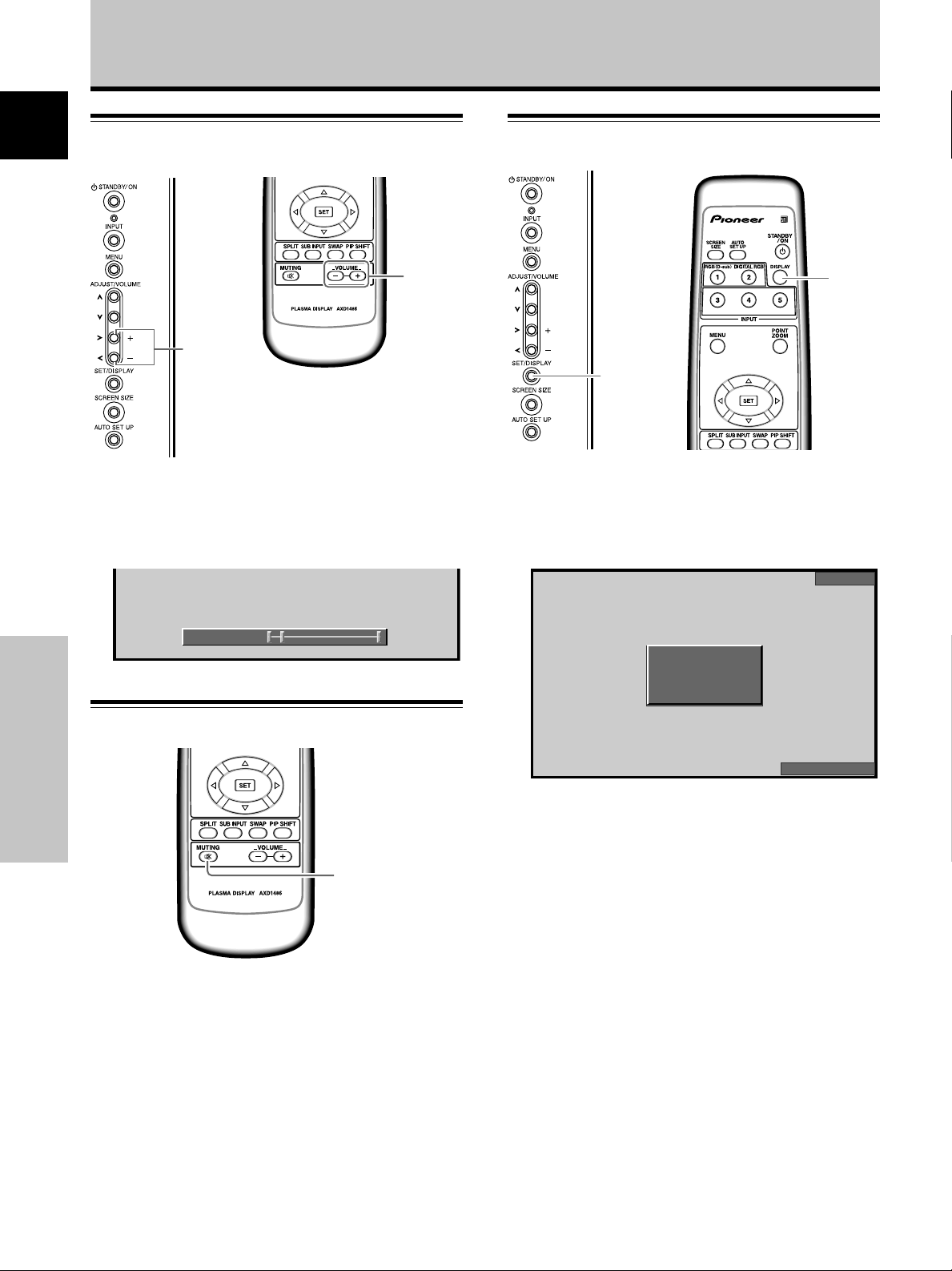
Adjusting sound volume
VOLUME
[+/–]
Remote control unit
Main unit operating panel
Press the VOLUME buttons.
Press the [–] or [+] button to respectively decrease and
increase the volume of sound from the speakers.
VOLUME
[+/–]
Confirming current status
DISPLAY
DISPLAY
Main unit operating panel Remote control unit
Press the DISPLAY button.
The currently selected input, screen size and refresh rates
will be displayed for about 3 seconds.
INPUT1
:
5VOLUME
Muting the sound
Operation
MUTING
Press the MUTING button on the remote control
unit.
Press the MUTING button again to restore the sound.
Muting is automatically canceled about 8 minutes after
the button is pressed, and the volume level is adjusted to
the minimum level.
Press VOLUME + or VOLUME – to adjust the volume at
a desired level.
:
:
Notes
¶ The displayed refresh rates may be slightly different from
actual values.
¶ When using the Point zoom function (page 22) or Multiscreen
function (page 23), the position and input information for the
enlarged screen area will be displayed.
¶ When the screen management function is active, the
[SCREEN MGT.] message will also be displayed at the lower
left corner of the screen.
k
531
HzfV .
060
X
460 840
HzfH .
ODBYTDOT
20
En
Page 25
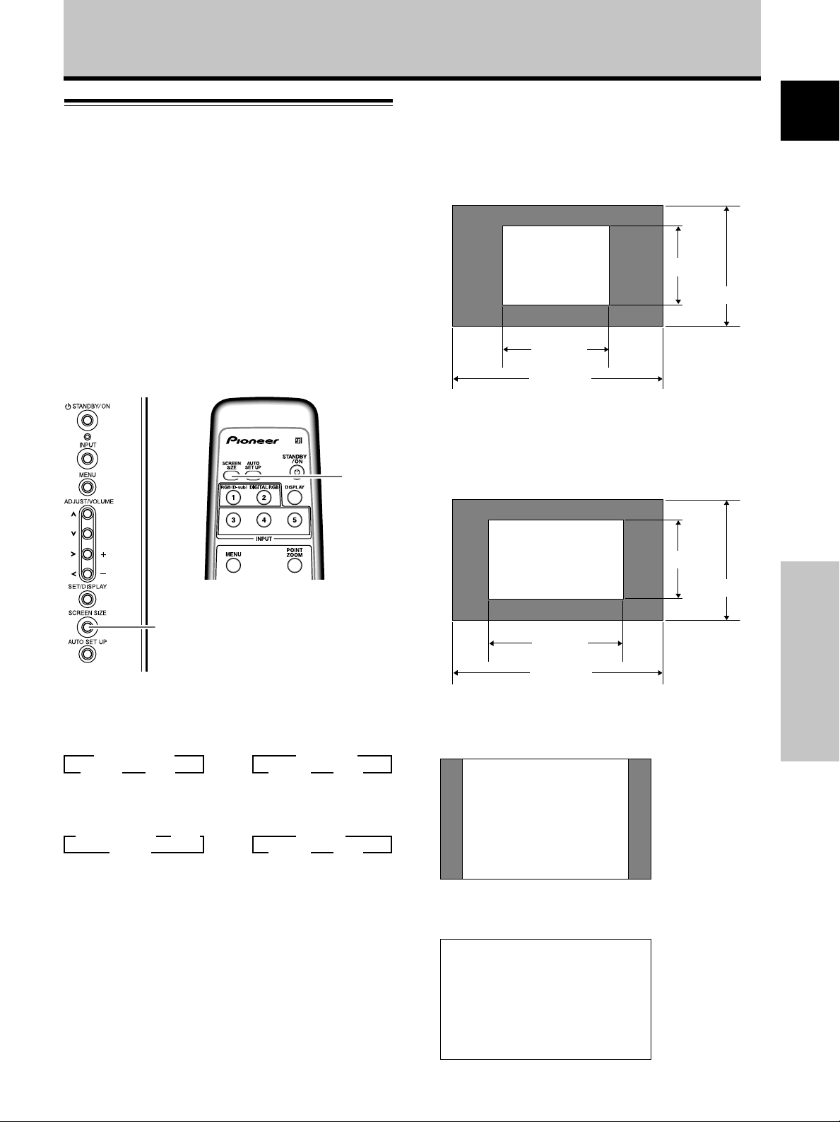
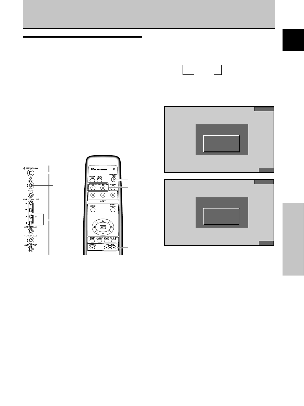
Changing screen size
This unit incorporates screen modes of various height and
width ratios. For optimal viewing, we recommend that
you select the screen mode that best matches the video
source that you are viewing. Although these modes are
designed for full display of a picture on a wide screen, it is
our hope that you make use of them with a full
understanding of the manufacturer’s intentions.
Operation
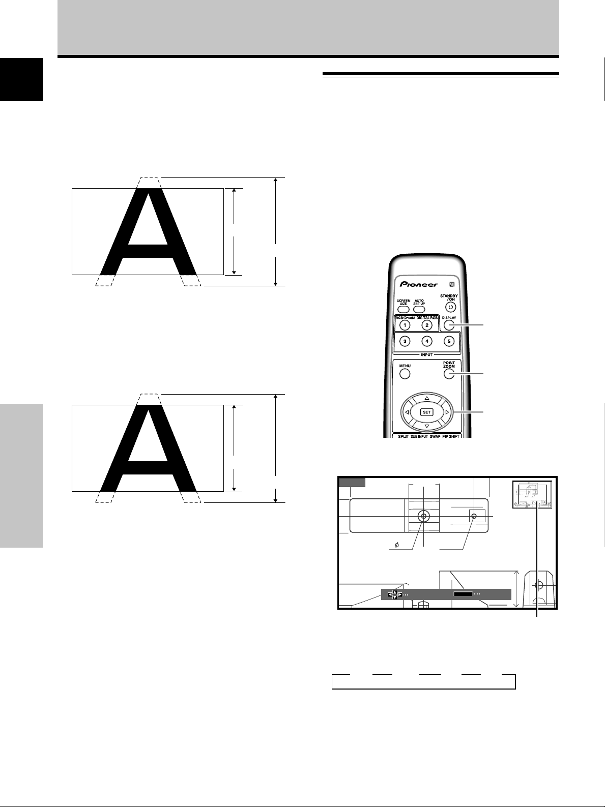
During personal computer signal input
1 DOT BY DOT
The input signal and the screen maintain a dot to line ratio
of 1:1 and is thus highly faithful to the source.
[PDP-50MXE10/PDP-50MXE11/PDP-50MXE1/
PDP-50MXE1-S]
480 lines
English
Screen size selection
The size of the image displayed on the screen, and the
range of the image shown can be set in one of four modes.
Press the SCREEN SIZE button to select the size.
SCREEN
SIZE
Remote control unit
SCREEN SIZE
Main unit operating panel
The screen size changes each time the SCREEN SIZE
button is pressed as follows.
[PDP-50MXE10/PDP-50MXE11/PDP-50MXE1/
PDP-50MXE1-S]
3 DOT BY DOT
FULL 2 4:3 2
or
3 PARTIAL
FULL 2 4:3 2
A
640 dots
1280 dots
(Illustration shows 640 x 480 input.)
[PDP-43MXE1/PDP-43MXE1-S]
* The PDP-43MXE1/PDP-43MXE1-S is designed with
horizontally oblong elements, with the result that
the image displayed will appear more oblong than
the original input signal.
A
640 dots
1024 dots
(Illustration shows 640 x 480 input.)
2 4:3
The display fills the screen as much as possible without
altering the aspect ratio of the input signal.
768 lines
480 lines
768 lines
Operation
[PDP-43MXE1/PDP-43MXE1-S]
3 DOT BY DOT 3 4:3
FULL 2
Consult the Computer signal compatibility table (pages 38
to 41) for information regarding screen sizes supported by
each signal format.
Notes
÷ When the [PARTIAL], [ZOOM] or [FULL] setting is used to
display a non-wide screen 4:3 picture fully on a wide screen, a
portion of the picture may be cut off or appear deformed.
÷ Be aware that when the display is used for commercial or
public viewing purposes, selecting the [PARTIAL], [ZOOM] or
[FULL] mode settings may violate the rights of authors
protected under copyright law.
÷ When [DOT BY DOT] or [4:3] screen size is selected, the
display position is moved slightly each time the power is
turned on, in order to prevent image burning.
or
3 ZOOM
FULL 2 4:3 2
A
3 FULL
The display is presented with a widescreen aspect ratio
of 16:9 and fills the entire screen.
A
21
En
Page 26
Operation
4 PARTIAL (*Supported only on PDP-50MXE10/PDP-
English
50MXE11/PDP-50MXE1/PDP-50MXE1-S)
The [PARTIAL] setting is available only during personal
computer input (1280 x 1024 input only).
The input signal and the screen maintain a dot to line ratio
of 1:1. Display is highly faithful to the source. However, in
order to maintain the 1:1 ratio, a portion of the display will
not appear on the screen.
768 lines
Use the 5/∞ buttons to adjust the vertical position of the
video image on the screen.
5 ZOOM (*Supported only on PDP-43MXE1/PDP-
43MXE1-S)
The [ZOOM] setting is available only during personal
computer input (1280 x 1024 input only).
A portion of the display will not appear on the screen.
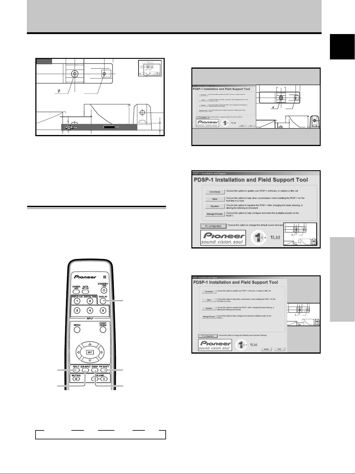
Enlarging one part of the screen
(POINT ZOOM)
This plasma display allows enlarging of the screen image
by ratios of [x 1.5], [x 2], and [x 3]. When enlarging the
screen, the 5/∞/2/3 buttons can be used to move the
enlarged viewing area around the screen.
¶ The range of zoom possible can be confirmed by viewing
the Zoom-Area subscreen at the upper right of the main
screen. The Zoom-Area subscreen is displayed for about
three seconds whenever the POINT ZOOM button, one
of the 5/∞/2/3 buttons, or DISPLAY button is pressed.
1024 lines
DISPLAY
POINT
ZOOM
768 lines
Operation
Use the 5/∞ buttons to adjust the vertical position of the
video image on the screen.
Moving the screen position
upward or downward
Press the 5/∞ buttons.
When playing a [PARTIAL] or [ZOOM] image (1280 x 1024
input only) from a computer, the vertical position of the
screen image can be adjusted. This adjusted position
cannot, however, be stored in memory.
Note
The image cannot be moved in the horizontal direction.
22
En
1024 lines
5/∞/2/3
1 Press the remote control unit’s POINT ZOOM
button.
x 1.5
Each time the POINT ZOOM button is pressed, the
zoom ratio alternates in the following order:
3 OFF 3 x 1.5 3 x 2 3 x 3
Notes
¶ During use of the POINT ZOOM function, the screen size
cannot be changed.
¶ When using the plasma display in a profit-making activity, or
when exhibiting images publicly, using the screen size function
to compress or stretch the image may result in infringement of
the copyrights of the image owners.
24
66.0
SCROLL
10
R12
22.1
P.ZOOM
ZOOM
Zoom-Area subscreen
Page 27
Operation
50
2 Using the 5/∞/2/3 buttons, move the screen to
the desired part of the image.
x 1.5
SCROLL
R12
22.1
P.ZOOM
ZOOM
24
10
84.3
÷ Pressing the POINT ZOOM and 5/∞/2/3 buttons
again will change the zoom ratio and the position of
screen enlarged.
÷ If the input signal changes, or if the menu screen is
displayed and the input is changed, or if the
multiscreen mode is selected, the POINT ZOOM
function will be canceled.
Multiscreen display
The plasma display’s multiscreen function allows the
simultaneous display of two inputs. The multiscreen
display include three modes, 2-SCREEN, PinP, and PoutP.
1 2-SCREEN
The main screen is displayed on the left and the
English
subscreen on the right.
66.0
R12
24
10
22.1
10
2 PinP
The subscreen is displayed in one of the four corners
of the main screen.
66.0
R12
24
22.1
10
3 PoutP
The subscreen is displayed outside the right side of
the main screen.
DISPLAY
SPLIT
SUB INPUT
PIP SHIFT
SWAP
1 Press the remote control unit’s SPLIT button.
Each time the button is pressed the multiscreen
display changes in the following order:
3 2-SCREEN 3 PinP 3 PoutP 3 OFF
66.0
R12
24
22.1
10
2 Press the remote control unit’s SUB INPUT button
to select the subscreen input source.
To exchange the main screen and subscreen
inputs
Press the remote control unit’s SWAP button.
¶ When 2-SCREEN mode has been selected:
The right and left sides of the display will switch; what
was previously the main screen will now show the
subscreen, and vice versa.
¶ When PinP or PoutP has been selected:
What was previously the main screen image will now
appear in reduced size as the subscreen image, and
vice versa.
23
Operation
En
Page 28
Operation
To change the position of the subscreen in PinP
mode:
English
Press the remote control unit’s PIP SHIFT.
Each time the button is pressed, the position of the
subscreen moves in the following order:
3 Lower right 3 Upper right
Lower left 2 Upper left 2
To display the currently selected input:
Press the DISPLAY button.
If the DISPLAY button is pressed while in multiscreen
mode, the main screen and sub-screen will each be
displayed with its currently selected input.
Notes
¶ When using the plasma display in a profit-making activity, or
when exhibiting images publicly, using the screen size function
to compress or stretch the image may result in infringement of
the copyrights of the image owners.
¶ If the multiscreen display is left on for an extended period of
time, or if the same multiscreen display is repeatedly shown
for short periods on an everyday basis, a residual image
pattern may be burned onto the screen.
¶ When selecting the 2-SCREEN mode, the screen image may
appear somewhat rougher, depending on the source used.
¶ The multiscreen mode will be canceled if a menu is opened, or
if POINT ZOOM is performed.
¶ The screen size cannot be changed during multiscreen display.
¶ The sound of the input selected in the main screen is
outputted when using the multiscreen function.
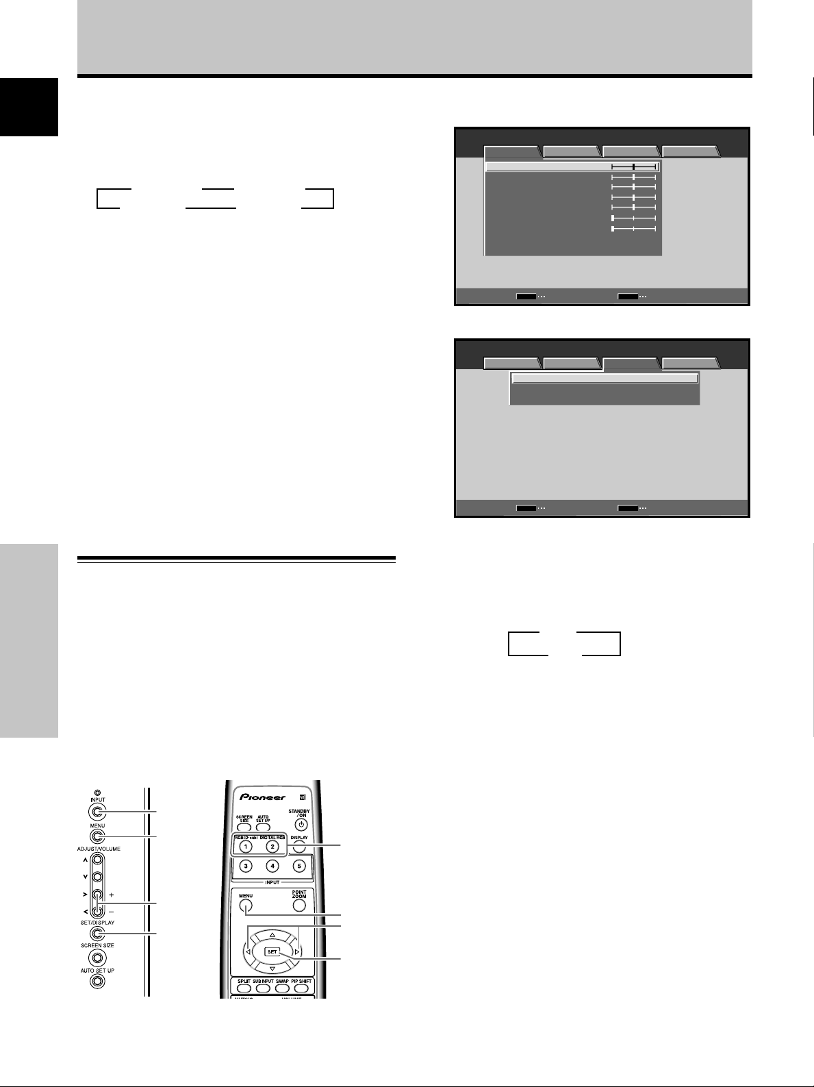
1 Press the MENU button to display the menu
screen.
MENU INPUT1
PICTURE SCREEN SETUP OPTION
ENTER
:
0
:
0
:
0
:
0
:
0
:
0
:
0
MENU
EXIT
CONTRAST
BRIGHTNESS
R.LEVEL
G.LEVEL
B.LEVEL
H.ENHANCE
V.ENHANCE
PICTURE RESET
SET
2 Use the 2/3 buttons to select [SETUP].
MENU INPUT1
PICTURE SCREEN SETUP OPTION
MENU
:
OFF
:
AUTO
:
:
V
GA
POWER MANAGEMENT
CLAMP POSITION
SIGNAL FORMAT
SET
CHANGE EXIT
Automatic power-off
(POWER MANAGEMENT)
This display is equipped with [POWER MANAGEMENT]
function, which allows the unit to automatically switch to
Operation
standby mode when no sync signal is detected.
(A warning message is displayed before this function
operates.)
Note
Always turn off the plasma display’s main power switch when
not using the display for extended periods of time.
INPUT
MENU
2/3
SET
Main unit operating
panel
24
En
Remote control unit
INPUT
MENU
2/3
SET
3 Press the SET button to confirm selection of
[POWER MANAGEMENT].
The factory default setting is [OFF].
Each time the button is pressed, the setting alternates
as follows:
3 OFF
ON 2
÷ OFF ..... The display will continue in operating mode,
regardless of the presence/absence of an
input sync signal.
÷ ON ....... If a sync signal is not detected, a warning
message is first displayed for 8 seconds,
after which the display automatically enters
the standby mode (*1), and the ON indicator
flashes green. If a sync signal is input again
later, the plasma display automatically
returns to normal operating mode (*2).
*1. Power consumption about 1W
*2. Except when input signal is G ON SYNC or
composite SYNC
4 When the setup is finished, press the MENU
button to exit the menu screen.
Note
The [POWER MANAGEMENT] function must be set individually
for each input (INPUT1 or INPUT2).
To return to operating mode:
To return to normal operation from the [POWER
MANAGEMENT] function’s standby mode, either operate
your computer, or press the INPUT button on the plasma
display or remote control unit.
Page 29
PICTURE/SCREEN Adjustment
PICTURE adjustment
MENU
5/∞
2/3
SET
Main unit operating
Remote control unit
panel
1 Press the MENU button to display the menu
screen.
MENU INPUT1
PICTURE SCREEN SETUP OPTION
CONTRAST
BRIGHTNESS
R.LEVEL
G.LEVEL
B.LEVEL
H.ENHANCE
V.ENHANCE
PICTURE RESET
:
0
:
0
:
0
:
0
:
0
:
0
:
0
MENU
2/3
SET
5/∞
4 Press the SET button.
Pressing the SET button writes the value into the
memory and returns the display to the step 2 screen.
5 When the setup is finished, press the MENU
button to exit the menu screen.
Note
Make these adjustments for each input (INPUT1 or INPUT2) and
signals.
[PICTURE] mode adjustment items
Below are brief descriptions of the options that can be set
in the [PICTURE] mode.
CONTRAST ············· Adjust according to the surrounding
brightness so that the picture can be
seen clearly.
BRIGHTNESS ·········· Adjust so that the dark parts of the
picture can be seen clearly.
R. LEVEL ················· Adjust the amount of red in the
picture.
G. LEVEL ················· Adjust the amount of green in the
picture.
B. LEVEL ················· Adjust the amount of blue in the
picture.
H. ENHANCE··········· Sharpens the image in the horizontal
direction.
V. ENHANCE ··········· Sharpens the image in the vertical
direction.
English
SET
ENTER
MENU
EXIT
2 Use the 5/∞ buttons to select the adjustment
item, then press the SET button.
MENU INPUT1
PICTURE SCREEN SETUP OPTION
CONTRAST
BRIGHTNESS
R.LEVEL
G.LEVEL
B.LEVEL
H.ENHANCE
V.ENHANCE
PICTURE RESET
SET
:
0
:
0
:
0
:
0
:
0
:
0
:
0
ENTER EXIT
MENU
3 Use the 2/3 buttons to adjust the picture quality
as desired.
:
MENU
0
EXIT
BRIGHTNESS
SET
SET
To reset [PICTURE] mode settings to the default
If settings have been adjusted excessively or the picture
on the screen no longer appears natural, it may prove
more beneficial to reset the [PICTURE] mode to default
settings instead of trying to make adjustments under
already adjusted conditions.
1 In step 2 in the previous procedure, use the 5/∞
buttons to select [PICTURE RESET], then press the
SET button.
PICTURE RESET
MENU
NO
EXIT
YES
SET
SET
2 Use the 2/3 buttons to select [YES], and press
the SET button.
All [PICTURE] mode settings are returned to the
factory set default.
25
PICTURE/SCREEN Adjustment
En
Page 30
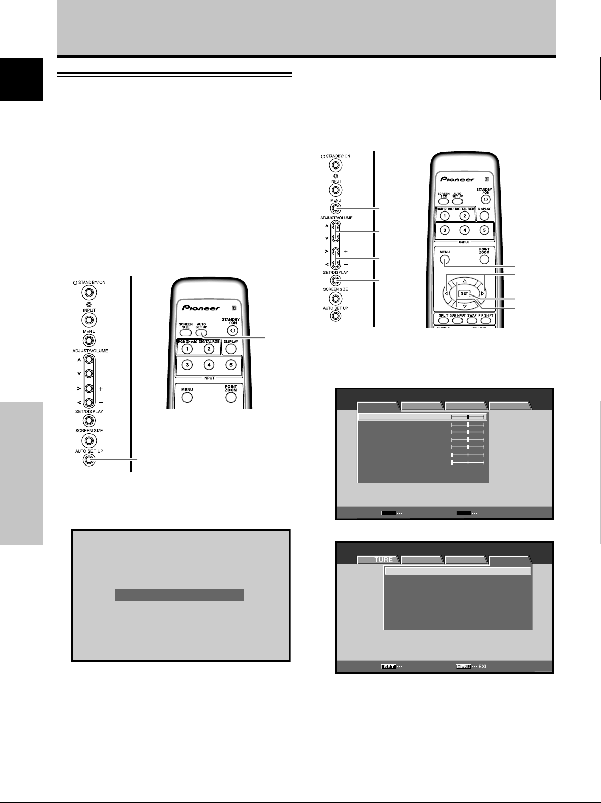
PICTURE/SCREEN Adjustment
English
Adjusting screen POSITION, CLOCK,
and PHASE
By pressing the AUTO SET UP button on either remote
control unit or the plasma display’s operating panel (or by
selecting [AUTO SET UP MODE] from the menu), the unit
will automatically set the screen position and clock to
best match the current image input.
<automatic adjust>
When the automatic setup mode is
selected, the unit will automatically be
adjusted to the optimum image settings
whenever the power is turned on, the input
source is changed, or the type of input
signal is changed.
Note
This setting is supported only when INPUT1 is selected. The
function is disabled when INPUT2 is selected.
When the button is pressed, the optimum
settings are automatically selected for the
current input source.
AUTO
SET UP
Remote control unit
AUTO SET UP
Main unit operating panel
MENU
5/∞
2/3
SET
Main unit operating
Remote control unit
MENU
2/3
SET
5/∞
panel
1 Press the MENU button to display the menu
screen.
MENU INPUT1
PICTURE SCREEN SETUP OPTION
CONTRAST
BRIGHTNESS
R.LEVEL
G.LEVEL
B.LEVEL
H.ENHANCE
V.ENHANCE
PICTURE RESET
:
0
:
0
:
0
:
0
:
0
:
0
:
0
Press the AUTO SET UP button on either the main
unit or remote control unit.
PICTURE/SCREEN Adjustment
AUTO SET UP
Note
Optimum settings may not be possible for low-luminance and
certain other signals. In such cases, set the [AUTO SET UP
MODE] to [INACTIVE], and use the manual adjustment methods
explained in the following section, “Adjusting screen
POSITION, CLOCK, and PHASE <manual adjust>“.
26
En
SET
ENTER
MENU
EXIT
2 Use the 2/3 buttons to select [OPTION].
MENU INPUT1
PICTURE SCREEN SETUP OPTION
MENU
:
:
STANDARD
:
OFF
:
:
:
:
:
EXIT
LANGUAGE ENGLISH
ENERGY SAVE
SCREEN MGT.
ORBITER OFF
MASK CONTROL ON
AUTO SET UP MODE INACTIVE
AUTO FUNCTION OFF
AUDIO OUT FIXED
SET
ENTER
Page 31

3 Use the 5/∞ buttons to select [AUTO SET UP
MODE].
MENU INPUT1
PICTURE SCREEN SETUP OPTION
MENU
:
:
STANDARD
:
OFF
:
:
:
:
:
LANGUAGE ENGLISH
ENERGY SAVE
SCREEN MGT.
ORBITER OFF
MASK CONTROL ON
AUTO SET UP MODE INACTIVE
AUTO FUNCTION OFF
AUDIO OUT FIXED
SET
CHANGE EXIT
4 Press the SET button to activate the setting.
The factory default setting is [INACTIVE].
Each time the button is pressed, the setting alternates
as follows:
3 INACTIVE
PICTURE/SCREEN Adjustment
Adjusting screen POSITION, CLOCK,
and PHASE
<manual adjust>
MENU
5/∞
2/3
SET
MENU
2/3
SET
5/∞
English
ACTIVE 2
5 When finished with the setting, press the MENU
button to return to the normal screen image.
Note
Optimum settings may not be possible for low-luminance and
certain other signals. In such cases, set the [AUTO SETUP
MODE] to [INACTIVE], and use the manual adjustment methods
explained in the following section, “Adjusting screen
POSITION, CLOCK, and PHASE <manual adjust>“.
Main unit operating
Remote control unit
panel
1 Press the MENU button to display the menu
screen.
MENU INPUT1
PICTURE SCREEN SETUP OPTION
ENTER
:
0
:
0
:
0
:
0
:
0
:
0
:
0
MENU
EXIT
CONTRAST
BRIGHTNESS
R.LEVEL
G.LEVEL
B.LEVEL
H.ENHANCE
V.ENHANCE
PICTURE RESET
SET
2 Use the 2/3 buttons to select [SCREEN].
MENU INPUT1
PICTURE SCREEN SETUP OPTION
POSITION
CLOCK
PHASE
SCREEN RESET
:
00
:
0
:
0
/
PICTURE/SCREEN Adjustment
SET
ENTER EXIT
MENU
27
En
Page 32

PICTURE/SCREEN Adjustment
3 Use the 5/∞ buttons to select the adjustment
English
item, then press the SET button.
MENU INPUT1
PICTURE SCREEN SETUP OPTION
POSITION
CLOCK
PHASE
SCREEN RESET
SET
ENTER EXIT
:
00
:
0
:
0
MENU
/
4 Use the 2/3 and 5/∞ buttons to select the
desired value.
÷ When the [POSITION] item is selected, the 2/3
buttons control movement in the Horizontal
direction (H), and the 5/∞ buttons control
movement in the Vertical direction (V).
POSITION
H V
00
SET
÷ Use the 2/3 buttons for the adjustments of
[CLOCK] and [PHASE].
PICTURE/SCREEN Adjustment
SET
MENU
EXIT
[SCREEN] mode adjustment items
Below are brief descriptions of the options that can be set
in the [SCREEN] mode.
POSITION
H ··························· Adjust the picture’s position to the
left or right.
V ···························· Adjust the picture’s position upward
or downward.
CLOCK ···················· Adjust letter breakup or noise on the
screen. This setting adjusts the
unit’s internal clock signal frequency
that corresponds to the input video
signal.
PHASE····················· Adjust so that there is minimum
flicker of screen letters or color
misalignment. This setting adjusts
the phase of the internal clock signal
adjusted by the [CLOCK] setting.
Notes
÷ The [CLOCK] and [PHASE] adjustment items are supported
only for INPUT1.
÷ When the [CLOCK] frequency is changed, the [POSITION]
command’s horizontal [H] option may require readjustment.
÷ If the adjustment items in the [SCREEN] mode are adjusted
excessively, the picture may not be displayed properly.
÷ When the [AUTO SET UP MODE] set to [ACTIVE], selecting the
[POSITION] and [LOCK] adjust modes will cause a message to
be displayed on the screen, but adjustment is possible.
However, if the input source is changed, the adjustment value
stored in memory will be the one automatically set with the
auto setup mode. If you wish to record a manually set
adjustment value, set the [AUTO SET UP MODE] to
[INACTIVE] (page 26) before beginning your adjustments.
To reset [SCREEN] mode settings to the default
If settings have been adjusted excessively or the picture
on the screen no longer appears natural, it may prove
more beneficial to reset the [SCREEN] mode to default
settings instead of trying to make adjustments under
already adjusted conditions.
1 In step 3 in the previous procedure, use the 5/∞
buttons to select [SCREEN RESET], then press the
SET button.
CLOCK
SET
SET
:
0
MENU
EXIT
Note
If INPUT2 is selected, only the [POSITION] can be adjusted.
5 Press the SET button.
Pressing the SET button writes the value into the
memory and returns the display to the step 3 screen.
6 When adjustment is finished, press the MENU
button to exit the menu screen.
28
En
SCREEN RESET
MENU
NO
EXIT
YES
SET
SET
2 Use the 2/3 buttons to select [YES], and press
the SET button.
All [SCREEN] mode settings are returned to the
factory set default.
Page 33

Other Operations
Setting the orbiter (ORBITER)
At set time intervals (about once every 8 minutes), this
function automatically changes the screen display
position by incremental amounts. The amount of screen
movement is 1 pixel horizontally or vertically.
When displaying a still image, setting [ORBITER] to [ON]
helps prevent the screen from being burnt with a lag
image.
÷ This function is not supported when using the POINT
ZOOM function, multiscreen function, or menu display.
Note
The [ORBITER] setting affects all input sources.
3 Use the 5/∞ buttons to select [ORBITER].
MENU INPUT1
PICTURE SCREEN SETUP OPTION
LANGUAGE ENGLISH
ENERGY SAVE
SCREEN MGT.
ORBITER OFF
MASK CONTROL ON
AUTO SET UP MODE INACTIVE
AUTO FUNCTION OFF
AUDIO OUT FIXED
:
:
STANDARD
:
OFF
:
:
:
:
:
4 Press the SET button to activate the setting.
The factory default setting is [OFF].
Each time the button is pressed, the setting alternates
as follows:
3 OFF
ON 2
5 When finished with the setting, press the MENU
button to return to the normal screen image.
English
MENU
5/∞
2/3
SET
Main unit operating
Remote control unit
MENU
2/3
SET
5/∞
panel
1 Press the MENU button to display the menu
screen.
MENU INPUT1
PICTURE SCREEN SETUP OPTION
CONTRAST
BRIGHTNESS
R.LEVEL
G.LEVEL
B.LEVEL
H.ENHANCE
V.ENHANCE
PICTURE RESET
:
0
:
0
:
0
:
0
:
0
:
0
:
0
Side mask position
(MASK CONTROL)
When screen size is set to [DOT BY DOT] or [4:3], or
when using multiscreen display, the position of the black
stripes on the side of the screen and the position of the
subscreen are changed slightly each time the power is
turned on, in order to alleviate burning of lag images on
the screen.
MENU
5/∞
2/3
SET
MENU
2/3
SET
5/∞
Other Operations
2 Use the 2/3 buttons to select [OPTION].
MENU INPUT1
PICTURE SCREEN SETUP OPTION
MENU
:
:
STANDARD
:
OFF
:
:
:
:
:
EXIT
LANGUAGE ENGLISH
ENERGY SAVE
SCREEN MGT.
ORBITER OFF
MASK CONTROL ON
AUTO SET UP MODE INACTIVE
AUTO FUNCTION OFF
AUDIO OUT FIXED
SET
ENTER
Main unit operating
Remote control unit
panel
1
Press the MENU button to display the menu screen.
MENU INPUT1
PICTURE SCREEN SETUP OPTION
CONTRAST
BRIGHTNESS
R.LEVEL
G.LEVEL
B.LEVEL
H.ENHANCE
V.ENHANCE
PICTURE RESET
:
0
:
0
:
0
:
0
:
0
:
0
:
0
29
En
Page 34

Other Operations
2 Use the 2/3 buttons to select [OPTION].
English
MENU INPUT1
PICTURE SCREEN SETUP
LANGUAGE ENGLISH
ENERGY SAVE
SCREEN MGT.
ORBITER OFF
MASK CONTROL ON
AUTO SET UP MODE INACTIVE
AUTO FUNCTION OFF
AUDIO OUT FIXED
:
:
STANDARD
:
OFF
:
:
:
:
:
3 Use the 5/∞ buttons to select [MASK CONTROL].
MENU INPUT1
PICTURE SCREEN SETUP OPTION
LANGUAGE ENGLISH
ENERGY SAVE
SCREEN MGT.
ORBITER OFF
MASK CONTROL ON
AUTO SET UP MODE INACTIVE
AUTO FUNCTION OFF
AUDIO OUT FIXED
:
:
STANDARD
:
OFF
:
:
:
:
:
4 Press the SET button to activate the setting.
The factory default setting is [ON].
Each time the button is pressed, the setting alternates
as follows:
3 OFF
ON 2
5 When finished with the setting, press the MENU
button to return to the normal screen image.
Note
The [MASK CONTROL] setting affects all input sources.
Screen management settings
OPTION
1 Press the MENU button to display the menu
screen.
MENU INPUT1
PICTURE SCREEN SETUP OPTION
CONTRAST
BRIGHTNESS
R.LEVEL
G.LEVEL
B.LEVEL
H.ENHANCE
V.ENHANCE
PICTURE RESET
:
0
:
0
:
0
:
0
:
0
:
0
:
0
2 Use the 2/3 buttons to select [OPTION].
MENU INPUT1
PICTURE SCREEN SETUP
LANGUAGE ENGLISH
ENERGY SAVE
SCREEN MGT.
ORBITER OFF
MASK CONTROL ON
AUTO SET UP MODE INACTIVE
AUTO FUNCTION OFF
AUDIO OUT FIXED
OPTION
:
:
STANDARD
:
OFF
:
:
:
:
:
3 Use the 5/∞ buttons to select [SCREEN MGT.],
then press the SET button.
MENU INPUT1
PICTURE SCREEN SETUP OPTION
LANGUAGE ENGLISH
ENERGY SAVE
SCREEN MGT.
ORBITER OFF
MASK CONTROL ON
AUTO SET UP MODE INACTIVE
AUTO FUNCTION OFF
AUDIO OUT FIXED
:
:
STANDARD
:
OFF
:
:
:
:
:
(SCREEN MGT.)
In order to alleviate burning of lag images in the screen,
this plasma display is equipped with a screen
Other Operations
management program that allows automatic switching of
the display image at regular intervals. The program can be
set to determine how the 24-hour screen management
cycle is repeated.
For information about detailed screen management
settings, consult your professional installation technician.
MENU
5/∞
2/3
SET
Main unit operating
panel
Remote control unit
MENU
2/3
SET
5/∞
4 Use the 5/∞ buttons to select [STATUS].
SCREEN MGT.
STATUS
TIME TO ACTIVATE
START
SET
RETURN
:
OFF
:
01H00M
MENU
EXIT
5 Use the 2/3 buttons to select [ONCE] or
[REPEAT].
The factory default setting is [OFF].
Each time the button is pressed, the setting alternates
as follows:
3 OFF 2
÷ ONCE ....... The screen management program is
performed once only.
÷ REPEAT .... The screen management program is
performed repeatedly (24-hour cycle ).
÷ OFF .......... Screen management program is
disabled, and normal screen image is
displayed continuously.
3 ONCE 2
3 REPEAT 2
30
En
Page 35

Other Operations
Under factory default settings, the screen display
contents will change as follows:
Set
[ONCE]
[TIME TO
ACTIVATE]
(set in step 7)
Set
[REPEAT]
[TIME TO
ACTIVATE]
(set in step 7)
Inverse
image*
10 minutes 30 minutes
Inverse
image*
10 minutes 30 minutes 10 minutes
* The color and brightness of the current image are displayed in
inverse values. The respective RGB color output levels are
inverted, with light areas appearing dark, and dark areas
appearing light.
White mask
display
White mask
display
24 hours
This cycle repeats
Power standby mode
Screen management
function ends here
Power
standby
mode
Inverse
image*
Notes
÷ When set to [ONCE], after the screen management program
ends, this part of the display will change to the [OFF]
message. If you wish to continue the screen management
program, use the 2/3 buttons to select [ONCE] again, or
change to [REPEAT].
÷ During screen management operation when set to [ONCE] or
[REPEAT], if the display’s MAIN POWER switch is turned OFF,
the screen management program will end, and this part of the
display will change to display the message [OFF]. If you wish
to continue the screen management program, use the 2/3
buttons to select [ONCE] or [REPEAT] again.
6 Use the 5/∞ buttons to select [TIME TO
ACTIVATE].
SCREEN MGT.
:
REPEATSTATUS
:
TIME TO ACTIVATE
START
SET
RETURN EXIT
01H00M
MENU
7 Use the 2/3 buttons to set the time you wish the
screen management program to begin.
When the 2/3 buttons are pressed, the screen
management operation can be set from 0 to 24 hours,
in 10-minute units.
8 Use the 5/∞ buttons to select [START].
9 Press the SET button.
The set value will be stored in memory, and the
screen will return to that shown in step 2.
The timer begins when the SET button is pressed,
and after passage of the time set in step 7, the screen
management program will begin operating.
10 When finished with the setting, press the MENU
button to return to the normal screen image.
Energy saving settings
(ENERGY SAVE)
The power control function allows screen brightness to
be suppressed as a means of lowering power
consumption and reducing display deterioration.
MENU
5/∞
2/3
SET
Main unit operating
Remote control unit
panel
1 Press the MENU button to display the menu
screen.
MENU INPUT1
PICTURE SCREEN SETUP OPTION
CONTRAST
BRIGHTNESS
R.LEVEL
G.LEVEL
B.LEVEL
H.ENHANCE
V.ENHANCE
PICTURE RESET
:
0
:
0
:
0
:
0
:
0
:
0
:
0
MENU
2/3
SET
5/∞
English
Other Operations
SCREEN MGT.
:
REPEATSTATUS
:
TIME TO ACTIVATE
START
SET
SET EXIT
00H10M
MENU
Note
The [SCREEN MGT.] setting affects all input sources.
2 Use the 2/3 buttons to select [OPTION].
MENU INPUT1
PICTURE SCREEN SETUP
LANGUAGE ENGLISH
ENERGY SAVE
SCREEN MGT.
ORBITER OFF
MASK CONTROL ON
AUTO SET UP MODE INACTIVE
AUTO FUNCTION OFF
AUDIO OUT FIXED
OPTION
:
:
STANDARD
:
OFF
:
:
:
:
:
31
En
Page 36

Other Operations
3 Use the 5/∞ buttons to select [ENERGY SAVE].
English
MENU INPUT1
PICTURE SCREEN SETUP OPTION
MENU
:
:
STANDARD
:
OFF
:
:
:
:
:
LANGUAGE ENGLISH
ENERGY SAVE
SCREEN MGT.
ORBITER OFF
MASK CONTROL ON
AUTO SET UP MODE INACTIVE
AUTO FUNCTION OFF
AUDIO OUT FIXED
SET
CHANGE EXIT
4 Press the SET button to select [ENERGY SAVE]
setting.
The factory default setting is [STANDARD].
Each time the SET button is pressed, the setting
changes as follows:
3 STANDARD
÷ STANDARD ... Brightness is controlled in
÷ MODE1 ......... Brightness is controlled in
÷ MODE2 ......... Brightness is controlled in accordance
÷ MODE3 ......... Brightness is set at fixed level,
Other Operations
÷ AUTO ............ Brightness is set automatically in
3 AUTO
MODE3 2
MODE2 2 MODE1 2
accordance with input signal to
produce bright, easily viewed image.
accordance with input signal, but
power consumption is less than that
used in [STANDARD] mode.
with input signal, but power
consumption is less than that used in
[MODE1].
regardless of input signal level.
Effective at reducing screen aging
due to burned lag images, etc.
response to ambient lighting
conditions so as to produce optimum
image appearance.
MENU
5/∞
2/3
SET
Main unit operating
Remote control unit
MENU
2/3
SET
5/∞
panel
1 Press the MENU button to display the menu
screen.
MENU INPUT1
PICTURE SCREEN SETUP OPTION
ENTER
:
0
:
0
:
0
:
0
:
0
:
0
:
0
MENU
EXIT
CONTRAST
BRIGHTNESS
R.LEVEL
G.LEVEL
B.LEVEL
H.ENHANCE
V.ENHANCE
PICTURE RESET
SET
2 Use the 2/3 buttons to select [OPTION].
MENU INPUT1
PICTURE SCREEN SETUP OPTION
LANGUAGE ENGLISH
ENERGY SAVE
SCREEN MGT.
ORBITER OFF
MASK CONTROL ON
AUTO SET UP MODE INACTIVE
AUTO FUNCTION OFF
AUDIO OUT FIXED
:
:
STANDARD
:
OFF
:
:
:
:
:
5 When finished with the setting, press the MENU
button to return to the normal screen image.
Note
The [ENERGY SAVE] setting affects all input sources.
Automatic input switching
(AUTO FUNCTION)
This display is equipped with an optional [AUTO
FUNCTION] selector. When enabled, the selector
automatically switches the display’s input source to INPUT1
when an image signal is detected at the INPUT1 terminal.
32
En
3 Use
SET
ENTER
MENU
EXIT
the 5/∞ buttons to select [AUTO FUNCTION].
MENU INPUT1
PICTURE SCREEN SETUP OPTION
MENU
:
:
STANDARD
:
OFF
:
:
:
:
:
LANGUAGE ENGLISH
ENERGY SAVE
SCREEN MGT.
ORBITER OFF
MASK CONTROL ON
AUTO SET UP MODE INACTIVE
AUTO FUNCTION OFF
AUDIO OUT FIXED
SET
CHANGE EXIT
Page 37

Other Operations
4 Press the SET button to select [INPUT1].
The factory default setting is [OFF]. Each time the
SET button is pressed, the selector function switches
alternately as shown:
3 OFF
INPUT1 2
÷ OFF .......... [AUTO FUNCTION] is disabled.
÷ INPUT1 ..... ÷ When a signal is detected at INPUT1,
the input source automatically
switches to [INPUT1].
÷ After the [AUTO FUNCTION] mode
has caused the input to switch, if the
input signal is no longer detected, the
input source reverts to the one
selected before operation of the
[AUTO FUNCTION] mode.
÷ If the input changes when the unit is
in [AUTO FUNCTION] mode, pressing
the INPUT button to select a different
input will cause the [AUTO
FUNCTION] mode to be temporarily
disabled, but it can be enabled again
by turning the power ON/OFF.
5 When finished with the setting, press the MENU
button to return to the normal screen image.
Notes
÷ The [AUTO FUNCTION] for [INPUT1] is supported only when a
separate SYNC or composite SYNC analog RGB signal is input.
(When a G ON SYNC or component video signal is input,
[AUTO FUNCTION] is disabled.)
÷ The [AUTO FUNCTION] setting affects all input sources.
1 Press the MENU button to display the menu screen.
MENU INPUT1
PICTURE SCREEN SETUP OPTION
CONTRAST
BRIGHTNESS
R.LEVEL
G.LEVEL
B.LEVEL
H.ENHANCE
V.ENHANCE
PICTURE RESET
:
0
:
0
:
0
:
0
:
0
:
0
:
0
2 Use the 2/3 buttons to select [OPTION].
MENU INPUT1
PICTURE SCREEN SETUP OPTION
MENU
:
:
STANDARD
:
OFF
:
:
:
:
:
EXIT
LANGUAGE ENGLISH
ENERGY SAVE
SCREEN MGT.
ORBITER OFF
MASK CONTROL ON
AUTO SET UP MODE INACTIVE
AUTO FUNCTION OFF
AUDIO OUT FIXED
SET
ENTER
3 Use the 5/∞ buttons to select [AUDIO OUT].
MENU INPUT1
PICTURE SCREEN SETUP OPTION
LANGUAGE ENGLISH
ENERGY SAVE
SCREEN MGT.
ORBITER OFF
MASK CONTROL ON
AUTO SET UP MODE INACTIVE
AUTO FUNCTION OFF
AUDIO OUT FIXED
:
:
STANDARD
:
OFF
:
:
:
:
:
English
About audio output (AUDIO OUT)
(PDP-50MXE1/PDP-50MXE1-S/PDP43MXE1/PDP-43MXE1-S only)
The signal level produced at the AUDIO (OUTPUT) jack
can be set to [FIXED] or [VARIABLE] (linked to the
VOLUME) as desired.
MENU
5/∞
2/3
SET
Main unit operating
panel
Remote control unit
MENU
2/3
SET
5/∞
SET
CHANGE EXIT
MENU
4 Press the SET button to select the desired audio
level setting.
The factory default setting is [FIXED].
Each time the SET button is pressed, the function
alternates as shown:
3 FIXED
VARIABLE 2
÷ FIXED ............ Audio output volume remains fixed,
even if the VOLUME controls are
operated.
÷ VARIABLE ..... Audio output volume changes in
response to operation of VOLUME
controls.
5 When finished with the setting, press the MENU
button to return to the normal screen image.
Notes
÷ The [AUDIO OUT] setting affects all input sources.
÷ On the PDP-50MXE10/PDP-50MXE11, only [VARIABLE] is
supported.
Other Operations
33
En
Page 38

English
Cleaning
Additional Information
Troubleshooting
Regular cleaning will extend the life and performance of
this unit. The recommended way to clean the display and
related parts is described below.
Before cleaning, be sure to unplug the power cord from
the power outlet.
Cleaning the display panel body and remote control
Do not under any circumstances use solvents such as
benzine or thinner for cleaner. Use of such liquids may
cause deterioration or peeling of paint from the display or
remote control unit.
Wipe the display and remote control gently with a soft
cloth. In the case of excessive dirt buildup, dampen a soft
cloth with a diluted neutral cleaning detergent and after
wringing the cloth thoroughly, wipe the component and
then dry it with a dry soft cloth.
Cleaning the screen
After dusting, wipe the screen gently using the supplied
cleaning cloth or another soft cloth (cotton, flannel, etc.).
Do not use tissue or a rough cloth. As the surface of the
screen is easily scratched, do not rub it or hit it with a
hard object.
If you clean the surface of the screen with a wet cloth,
water droplets on the surface may enter into the product,
resulting in malfunction.
Cleaning the vents
As a general rule, use a vacuum cleaner about once a
month to clean the vents on the rear panel of the display
of dust buildup (set the vacuum cleaner to its weakest
setting when doing this).
Additional Information
Using the unit without cleaning it of dust will cause the
internal temperature to increase, resulting in possible
breakdown or fire.
Vents
What may at first seem to be an malfunction, may be
remedied with a quick check.
Please check to see if a warning is displayed on the
screen. If displayed, refer to the table below and check
the mode. If there is no display check to see if the
problem is listed on page 35. The problem may also be
caused by something other than this unit so please also
check the other components being used such as a video
deck. If the problem can still not be solved please consult
the dealer where this unit was purchased.
About the self diagnosis mode
Messages appear on the bottom of this unit’s screen to
indicate operation or connection faults. After message
confirmation, check the condition of the unit.
ERROR MESSAGE
CAUTION
OUT OF RANGE
or
CAUTION
UNSUPPORTED SIGNAL
or
SIGNAL NG
WARNING
THERMAL ALERT
SHUT DOWN (**)
WARNING
FAN FAILURE
SHUT DOWN (**)
¶ The current input signal is
¶ Turn off main power (page
¶ Is ambient temperature
¶ Remove any objects
¶ Cooling fan has
REMEDY
not supported by the unit.
Check the Computer signal
compatibility table on
pages 38 to 41, and change
the computer’s output
signal setting appropriately.
9).
above 40 ˚C?
blocking the cooling vents
on the plasma display.
malfunctioned.
Immediately turn off
power, remove power plug
from its outlet, and consult
a Pioneer service center or
your dealer.
Vents
Vents
Illustration depicts PDP-50MXE10/PDP-50MXE11/
PDP-50MXE1/PDP-50MXE1-S model.
34
En
ERROR
INVALID KEY ENTRY
VentsVents
SHUT DOWN (**)
¶ An invalid operation has
been attempted. Check
input signals, connections
and other settings.
¶ Turn off main power, wait
for 1-2 minutes, then try
turning power on again. If
problem persists, remove
power plug from its outlet
and consult a Pioneer
service center or your
dealer.
In the above, messages contents indicated by (**)
represent numerals.
Page 39

General problems
Problem Possible Solution
• No power
• Unit cannot be operated.
• Remote control does not
operate.
• Picture is cut off.
• Strange color, light color, or
dark, or color misalignment
• Power is suddenly turned
off.
• No picture
Additional Information
English
• Is the power cord disconnected? (page 14)
• Has the MAIN POWER switch been switched on? (page 9)
• External influences such as lightning, static electricity, etc., may cause improper operation. In this
case, operate the unit after first turning the MAIN POWER off/on, or unplugging the power cord
and re-plugging it in after 1 to 2 minutes.
• Are batteries inserted with polarity (+, –) correctly aligned? (page 8)
• Are batteries worn out? (Replace with new batteries.)
• Is any object occluding the remote signal receiver? (page 8)
• Point the remote control unit toward the remote signal receiver when operating (page 8).
• Is the selected screen size correct?
Switch to another screen size (page 21).
• Are [SCREEN] mode adjustments such as picture size made correctly? (pages 21, 22 and 26 to 28)
• Is the POINT ZOOM function being used? (page 22)
• Adjust the picture tone (page 25).
• Is the room too bright?
The picture may look dark in a room that is too bright.
• Is [CLAMP POSITION] setup correct? (page 18)
• The unit’s internal temperature has increased. (Air vents are blocked.)
Remove any objects blocking vent or clean (page 34).
• Is the [POWER MANAGEMENT] function set to [ON]? (page 24)
• Is the [SCREEN MGT.] function set to [ONCE] or [REPEAT]? (pages 30 and 31)
• Is connection to other components correct? (pages 12 to 13)
• Has setup been done correctly after connection? (pages 16 to 18)
• Is the correct input selected? (page 19)
• Is a non-compatible signal being input? (pages 38 to 41)
• Is the [PICTURE] setting correct? (page 25)
Problems commonly mistaken as breakdown
Problem Possible Solution
• The screen is displayed in a
small size.
• Letter breakup on screen.
• A sharp sound is sometimes
heard from the cabinet.
• Bright portions of image
appear to be losing intensity.
• Speckles or noise appears on
screen.
• Stripes appear on the screen.
• Sound is heard from inside
the unit.
• Fan isn’t moving.
• Fan speed changes.
• ON (green) indicator doesn’t
light.
• Panel sounds/noises
• Is the correct screen size selected? (pages 21, 22, 26 and 27)
• Adjust using [SCREEN] mode on the menu screen (page 27).
If there is still no improvement, this unit may be limiting the displayable range. Check the
Computer signal compatibility table (pages 38 to 41).
• Expansion/contraction caused by surrounding temperature change may result in sound being
heard from the cabinet. This is not a malfunction.
• When the video input signal’s level is too high, the bright portions may appear to be losing their
intensity.
Increase the adjustment level of the contrast and check the picture (page 25).
• May be caused by radio wave interference from appliances with motors such as hair dryers,
electric vacuum cleaners, electric power drills, ignition systems of cars, motorcycles etc., switch
devises such as thermostats etc., neon signs or electrical discharge from power lines etc.
• May be caused by radio wave mingling from TV station, FM station, amateur radios, public radios
(simplified radios) etc., or a nearby personal computer, TV, or video/audio component.
• A strong electromagnetic field may cause picture distortion and similar problems.
• Normal sound of the cooling fan and internal sliding parts of the plasma display panel. Not a
malfunction.
• Fan is set to operate only after ambient temperature exceeds 35°C (differs depending on
installation conditions). Not a malfunction.
• Fan speed changes automatically in accordance with ambient conditions. Not a malfunction.
• The ON indicator may not light in some cases, depending on the settings performed by the
installer. Consult with your installation technician.
• Panel generated sounds, examples: Fan motor noise, Electrical Circuit Humming/Glass Panel
buzzing are normal operation of a phosphor-based matrix display.
Additional Information
35
En
Page 40

Additional Information
English
Precautions regarding use
Panel sticking and after-image lag
• Displaying the same images such as still images for a long
time may cause after-image lagging.
This may occur in the following two cases.
1. After-image lagging due to remaining electrical load
When image patterns with very high peak luminance are
displayed for more than 1 minute, after-image lagging may
occur due to the remaining electric load. The after-images
remaining on the screen will disappear when moving images
are displayed. The time for the after-images to disappear
depends on the luminance of the still images and the time
they had been displayed.
2. After-image (lag image) due to burning
Avoid displaying the same image on the Plasma Display
continuously over a long period of time. If the same image is
displayed continuously for several hours, or for shorter periods
of time over several days, a permanent after-image may
remain on the screen due to burning of the fluorescent
materials. Such images may become less noticeable if moving
images are later displayed, but they will not disappear
completely.
The same kind of burning of a lag image may also be produced
after extended multi-hour use, or recurrent daily use for shorter
periods of a single [4:3] screen size, or [DOT BY DOT] image.
Except in cases where violation of intellectual property rights
may be involved (pages 21 and 22), it is recommended that lagimage burning be avoided by selecting a screen size that
displays images over the entire screen (pages 21 and 22).
• In addition, the [ENERGY SAVE] function (page 31), [ORBITER]
function (page 29), [MASK CONTROL] function (page 29), and
[SCREEN MGT.] (page 30) can also be used to reduce the
chance of lag image formation.
Note
Special precautions must be employed when using the
plasma display as a surveillance monitor or in other
applications where a fixed image will be displayed for
Additional Information
extended periods of time. Before using the monitor in such
applications, consult your dealer for advice.
When using this unit as a monitor for a surveillance
camera, it is recommended to set the [ENERGY SAVE]
function to [MODE3] or [MODE2].
About the plasma panel’s protection function
The brightness of this display will deteriorate slightly when an
image with little movement such as a photograph or computer
image is continuously displayed. This is caused by the plasma
panel’s protection function which detects images with slight
movement and automatically adjusts brightness to protect the
display, and is not a malfunction.
The screen-saver function begins operating when the display
detects no or little screen movement for a period of about three
minutes; the function is an automatic feature and cannot be
turned OFF.
Pixel failure
The plasma display screen is composed of a high numbers of
tiny pixel elements constructed in a high-precision array, but on
occasion one or more of the pixels may fail to light, or may light
erratically. This is an inevitable by-product of the manufacturing
process and not a malfunction.
Concerning infrared light
In principle, the plasma display radiates infrared light. Depending
on the environment in which the monitor is installed and used,
infrared remote control units for other nearby appliances may fail
to operate properly, or noise may be heard in wireless
headphones. In such cases, move the affected appliance to a
location where its infrared sensor is not affected.
Electromagnetic interferrence
This unit is built in compliance with official standards for
eletromagnetic interference, but it nonetheless may produce a
low level of radio noise. This noise may be noticeable if AM
radios, computers, or video appliances are installed too close to
the display. In such cases, remove the affected appliance to a
location where it is not affected.
Additional cautions
• If the power is automatically turned off during operation of this
unit, the following reasons may be the cause.
1 Is the [POWER MANAGEMENT] function set to [ON]?
(page 24).
2 The surrounding temperature has risen above 40 °C.
The display should be used within ambient temperature
conditions below 40 °C.
3 The internal temperature has risen abnormally due to
blocked cooling vents, overheating of internal electronic
parts, or other factors.
If the power is automatically turned off for a reason other than
the above reasons, there could be a malfunction. In this case,
unplug the power cord from the power outlet and request
repair from your nearest sales outlet.
• The plasma display panel of this unit is very bright and viewing
it a close distance will cause eye strain.
We recommend that you view the screen from a suitable
distance (3 to 6 m).
• In order to protect the panel and internal circuitry, this display
is provided with a cooling fan designed to turn on/off and
change speed automatically in accordance with ambient
temperature conditions (the fan sound will change in
accordance with its speed). The display should be used within
ambient temperature conditions below 40 °C.
STANDBY and ON indicators
During operation of the [POWER MANAGEMENT] function, the
ON indicator will flash green at intervals of about 1 second (page
24).
The ON indicator lights steadily (green) under nomal operating
conditions. However, depending on the settings performed by
the installation technician, the green indicator may not light even
when power is turned on (page 35).
If the green light displays a flashing pattern other than the above,
an error message is indicated. Consult any onscreen messages
(page 34) and check ambient conditions (temperature, etc.) and
respond accordingly (page 35).
If the problem persists, disconnect the power plug and consult
your dealer or a service center.
Other than this, if the power turns off by itself, or refuses to turn
on, or if the STANDBY indicator conditions flashing red, a
malfunction may be indicated. Immediately disconnect the power
plug and consult your dealer or a service center.
36
En
Page 41

Specifications
General (PDP-50MXE10/PDP-50MXE11/PDP50MXE1/PDP-50MXE1-S)
Light emission panel .............. “50-inch” AC Plasma Panel
109.8 (W) x 62.1 (H) x 126.1 (diagonal) cm
Number of pixels .............................................. 1280 x 768
Power supply ............................. AC 100 - 240 V, 50/60 Hz
Rated current ................................................. 3.6 A - 1.5 A
Standby power consumption ...................................... 1 W
External dimensions
.... 1218 (W) x 714 (H) x 98 (D: Not including handles) mm
(including display stand)
...................................... 1218 (W) x 737 (H) x 300 (D) mm
Weight
PDP-50MXE10/PDP-50MXE1/PDP-50MXE1-S .... 41.0 kg
PDP-50MXE11 ................................................... 35.7 kg
Weight (including display stand)
PDP-50MXE10/PDP-50MXE1/PDP-50MXE1-S .... 41.6 kg
PDP-50MXE11 ................................................... 36.3 kg
Operating temperature range............................. 0 to 40 °C
Operating atmospheric pressure range
................................................................. 800 to 1100 hPa
General (PDP-43MXE1/PDP-43MXE1-S)
Light emission panel .............. “43-inch” AC Plasma Panel
95.2 (W) x 53.6 (H) x 109.3 (diagonal) cm
Number of pixels .............................................. 1024 x 768
Power supply ............................. AC 100 - 240 V, 50/60 Hz
Rated current ............................................. 2.98 A - 1.24 A
Standby power consumption ...................................... 1 W
External dimensions
.... 1070 (W) x 630 (H) x 98 (D: Not including handles) mm
(including display stand)
...................................... 1070 (W) x 653 (H) x 300 (D) mm
Weight.................................................................... 32.5 kg
(including display stand) ......................................... 33.1 kg
Operating temperature range............................. 0 to 40 °C
Operating atmospheric pressure range
................................................................. 800 to 1100 hPa
Additional Information
Input/output
Video
INPUT1
Input Mini D-sub 15 pin (socket connector)
RGB signal (G ON SYNC compatible)
RGB ... 0.7 Vp-p/75 Ω/no sync.
HD/VS, VD ... TTL level
/positive and negative polarity
/2.2 kΩ
G ON SYNC
... 1 Vp-p/75 Ω/negative sync.
*Compatible with Microsoft “Plug & Play”
(VESA DDC1/2B)
Output Mini D-sub 15 pin (socket connector)
75 Ω/with buffer
INPUT2
Input DVI-D 24-pin connector
Digital RGB signal (DVI compliant TMDS
signal)
*Compatible with Microsoft “Plug & Play”
(VESA DDC 2B)
Audio
Input AUDIO INPUT (for INPUT1)
Stereo mini jack
L/R ... 500 mVrms/more than 10 kΩ
AUDIO INPUT (for INPUT2)
Stereo mini jack
L/R ... 500 mVrms/more than 10 kΩ
Output AUDIO OUTPUT
Stereo mini jack
L/R ... 500 mVrms (max)/less than 5 kΩ
SPEAKER
L/R ... 8 – 16 Ω/7 W +7 W (at 8 Ω)
Control
RS-232C ... D-sub 9 pin (pin connector)
COMBINATION IN/OUT
... Mini DIN 6 pin (x2)
Accessories
Remote control unit ......................................................... 1
Remote control unit holder .............................................. 1
AA (R6) batteries .............................................................. 2
Cleaning cloth (for screen) ............................................... 1
Speed clamps................................................................... 2
Bead bands ...................................................................... 2
Display stands .................................................................. 2
Washers ........................................................................... 2
Hex hole bolts (M8X40).................................................... 2
Ferrite core ....................................................................... 1
Cable tie ........................................................................... 1
Operating Instructions...................................................... 1
English
Additional Information
÷ Due to improvements, specifications and design are subject to
change without notice.
37
En
Page 42

Additional Information
English
Appendix 1: Computer signal compatibility table
Appendix 1
Resolution
(Dot x Line)
640x400
720x400
640x480
848x480
800x600
832x624
1024x768
1280x768
1152x864
Additional Information
1152x870
1152x900
1280x960
1280x1024
1400x1050
1600x1200
-1/4: PDP-50MXE10/PDP-50MXE11/PDP-50MXE1/PDP-50MXE1-S (INPUT1)
Refresh rate
Vertical DOT BY DOT
56.4Hz
70.1Hz
85.1Hz
60Hz
66.7Hz
72.8Hz
75Hz
85Hz
60Hz
56Hz
60Hz
72Hz
75Hz
85Hz
74.6Hz
60Hz
70Hz
75Hz
(74.9Hz)
85Hz
56Hz
60Hz
70Hz
60Hz
72Hz
75Hz
75.1Hz
66Hz
76Hz
60Hz
60Hz
75Hz
85Hz
60Hz
75Hz
85Hz
60Hz
65Hz
70Hz
75Hz
85Hz
Horizontal 4:3
24.8kHz
31.5kHz
37.9kHz
31.5kHz
35.0kHz
37.9kHz
37.5kHz
43.3kHz
31.0kHz
35.2kHz
37.9kHz
48.1kHz
46.9kHz
53.7kHz
49.7kHz
48.4kHz
56.5kHz
60.0kHz
(60.2kHz)
68.7kHz
45.1kHz
47.8kHz
56.1kHz
53.7kHz
64.9kHz
67.5kHz
68.5kHz
61.8kHz
71.7kHz
60.0kHz
64.0kHz
80.0kHz
91.2kHz
65.3kHz
82.3kHz
93.9kHz
75.0kHz
81.3kHz
87.5kHz
93.8kHz
106.3kHz
640x480
±
±
±
±
848x480
800x600
±
±
±
±
832x624
1024x768
±
±
±
1280x768
±
±
Screen size (Dot x line)
FULL
1280x768
1280x768
±
1024x768
±
±
±
±
1024x768
±
±
±
±
1024x768
1024x768
±
±
1024x768
1024x768
±
1024x768
1024x768
±
±
1024x768
±
±
1024x768
±
±
±
±
1280x768
±
±
±
±
1280x768
1280x768
±
±
±
±
1280x768
1280x768
±
±
±
1280x768
±
±
1280x768
1280x768
±
1280x768
1280x768
±
±
1280x768
±
±
1280x768
±
±
±
±
PARTIAL
Apple Macintosh 13”
Apple Macintosh 16”
Apple Macintosh 21”
Sun Microsystems LO
Sun Microsystems HI
1280x768
±
±
: Not available.Computer signal compatibility table (INPUT1)
Remarks
NEC PC-9800
NEC PC-9800
(1072x600)
(1376 x 768)
( ) indicates Apple
Macintosh 19”
(1600x1024)
38
En
: Optimal picture. Adjustment of picture position, refresh rate, phase etc., may be necessary.
: Picture will be enlarged but some fine detail will be hard to see.
: Simple reproduction. Fine detail will not be reproduced.
Page 43

Additional Information
Appendix 1
Resolution
(Dot x Line)
640x480
848x480
800x600
1024x768
1280x768
1152x864
1280x960
1280x1024
1400x1050
-2/4: PDP-50MXE10/PDP-50MXE11/PDP-50MXE1/PDP-50MXE1-S (INPUT2)
Refresh rate
Vertical DOT BY DOT FULL PARTIAL
60Hz
60Hz
56Hz
60Hz
60Hz
56Hz
60Hz
60Hz
60Hz
60Hz
60Hz
Horizontal 4:3
31.5kHz
31.0kHz
35.2kHz
37.9kHz
48.4kHz
45.1kHz
47.8kHz
53.7kHz
60.0kHz
64.0kHz
65.3kHz
: Optimal picture. Adjustment of picture position, refresh rate, phase etc., may be necessary.
: Picture will be enlarged but some fine detail will be hard to see.
: Simple reproduction. Fine detail will not be reproduced.
640x480
848x480
800x600
±
1024x768
1280x768
±
Screen size (Dot x line)
1024x768
1024x768
±
1024x768
1024x768
1024x768
1024x768
1280x768
1280x768
1280x768
±
1280x768
1280x768
1280x768
1280x768
1280x768
1280x768
English
: Not available.Computer signal compatibility table (INPUT2)
Remarks
(1072x600)
(1376x768)
Note
In rare cases, a normal picture may not be obtained when switching between compatible signal formats on the output device (PC).
Should this happen, turn off the power and then turn it back on again.
Additional Information
39
En
Page 44

Additional Information
Appendix 1
English
Resolution
(Dot x Line)
640x400
720x400
640x480
848x480
800x600
832x624
1024x768
1280x768
1152x864
1152x870
Additional Information
1152x900
1280x960
1280x1024
1400x1050
1600x1200
-3/4: PDP-43MXE1/PDP-43MXE1-S (INPUT1)
Refresh rate
Vertical DOT BY DOT
56.4Hz
70.1Hz
85.1Hz
60Hz
66.7Hz
72.8Hz
75Hz
85Hz
60Hz
56Hz
60Hz
72Hz
75Hz
85Hz
74.6Hz
60Hz
70Hz
75Hz
(74.9Hz)
85Hz
56Hz
60Hz
70Hz
60Hz
72Hz
75Hz
75.1Hz
66Hz
76Hz
60Hz
60Hz
75Hz
85Hz
60Hz
75Hz
85Hz
60Hz
65Hz
70Hz
75Hz
85Hz
Horizontal 4:3
24.8kHz
31.5kHz
37.9kHz
31.5kHz
35.0kHz
37.9kHz
37.5kHz
43.3kHz
31.0kHz
35.2kHz
37.9kHz
48.1kHz
46.9kHz
53.7kHz
49.7kHz
48.4kHz
56.5kHz
60.0kHz
(60.2kHz)
68.7kHz
45.1kHz
47.8kHz
56.1kHz
53.7kHz
64.9kHz
67.5kHz
68.7kHz
61.8kHz
71.7kHz
60.0kHz
64.0kHz
80.0kHz
91.2kHz
65.3kHz
82.3kHz
93.9kHz
75.0kHz
81.3kHz
87.5kHz
93.8kHz
106.3kHz
640x480
±
±
±
±
848x480
800x600
±
±
±
±
832x624
1024x768
±
±
±
Screen size (Dot x line)
768x768
±
±
±
±
768x768
±
±
±
±
768x768
768x768
±
±
±
768x768
±
±
768x768
768x768
±
768x768
768x768
±
±
768x768
±
±
768x768
±
±
±
±
FULL
1024x768
1024x768
±
1024x768
±
±
±
±
1024x768
1024x768
±
±
±
±
1024x768
1024x768
±
±
1024x768
±
±
1024x768
1024x768
±
1024x768
1024x768
±
±
1024x768
±
±
1024x768
±
±
±
±
ZOOM
1024x768
±
±
: Not available.Computer signal compatibility table (INPUT1)
Remarks
NEC PC-9800
NEC PC-9800
Apple Macintosh 13”
(1072x600)
Apple Macintosh 16”
(1376 x 768)
( ) indicates Apple
Macintosh 19”
Apple Macintosh 21”
Sun Microsystems LO
Sun Microsystems HI
(1600x1024)
40
En
: Optimal picture. Adjustment of picture position, refresh rate, phase etc., may be necessary.
: Picture will be enlarged but some fine detail will be hard to see.
: Simple reproduction. Fine detail will not be reproduced.
Page 45

Additional Information
Appendix 1
Resolution
(Dot x Line)
640x480
848x480
800x600
1024x768
1280x768
1152x864
1280x960
1280x1024
1400x1050
-4/4: PDP-43MXE1/PDP-43MXE1-S (INPUT2)
Refresh rate
Vertical DOT BY DOT FULL ZOOM
60Hz
60Hz
56Hz
60Hz
60Hz
56Hz
60Hz
60Hz
60Hz
60Hz
60Hz
Horizontal 4:3
31.5kHz
31.0kHz
35.2kHz
37.9kHz
48.4kHz
45.1kHz
47.8kHz
53.7kHz
60.0kHz
64.0kHz
65.3kHz
: Optimal picture. Adjustment of picture position, refresh rate, phase etc., may be necessary.
: Picture will be enlarged but some fine detail will be hard to see.
: Simple reproduction. Fine detail will not be reproduced.
640x480
848x480
800x600
±
1024x768
Screen size (Dot x line)
768x768
768x768
±
768x768
768x768
768x768
768x768
768x768
1024x768
1024x768
1024x768
±
1024x768
±
1024x768
1024x768
1024x768
1024x768
1024x768
English
: Not available.Computer signal compatibility table (INPUT2)
Remarks
(1072x600)
(1376x768)
Note
In rare cases, a normal picture may not be obtained when switching between compatible signal formats on the output device (PC).
Should this happen, turn off the power and then turn it back on again.
Additional Information
41
En
Page 46

Additional Information
English
Appendix 2: INPUT1/2 pin assignments
Appendix 2-1/2:
INPUT1 (Mini D-sub 15 pin female connector) pin
allocation.
10
51
6
15 11
Pin No.
1
2
3
4
5
6
7
8
9
10
11
12
13
14
15
R
G
B
NC (No connection)
GND
GND
GND
GND
DDC + 5V
GND
NC (No connection)
DDC SDA
HD or H/V SYNC
VD
DDC SCL
Input Output
+
+
+
+
+
+
+
+
NC (No connection)
+
+
NC (No connection)
+
+
NC (No connection)
Appendix 2-2/2:
INPUT2 (DVI female connector) pin allocation.
18
Additional Information
Pin No.
1
2
3
4
5
6
7
8
9
10
11
12
13
14
15
16
9
Signal Assignment
T.M.D.S. Data2–
T.M.D.S. Data2+
T.M.D.S. Data2/4 Shield
NC (No connection)
NC (No connection)
DDC Clock
DDC Data
NC (No connection)
T.M.D.S. Data1–
T.M.D.S. Data1+
T.M.D.S. Data1/3 Shield
NC (No connection)
NC (No connection)
+5V Power
GND
Hot Plug Detect
16
2417
42
En
Pin No.
17
18
19
20
21
22
23
24
T.M.D.S. Data0 –
T.M.D.S. Data0 +
T.M.D.S. Data0/5 Shield
NC (No connection)
NC (No connection)
T.M.D.S. Clock Shield
T.M.D.S. Clock+
T.M.D.S. Clock–
Signal Assignment
Explanation of terms
Aspect ratio
The TV screen’s width to height ratio is referred to as its aspect
ratio. The aspect ratio on standard TVs is 4:3 and on wide TVs or
High Definition TVs it is 16:9.
G ON SYNC
This indicates a video signal in the form of a synchronization
signal added to the G (GREEN) signal of the R.G.B signal.
VGA
General term for “Video Graphics Array”.
Generally this indicates a 640 dot x 480 line resolution.
WVGA
General term for “Wide Video Graphics Array”.
Generally this indicates a 848 dot x 480 line resolution.
XGA
General term for “eXtended Graphics Array”.
Generally this indicates a 1024 dot x 768 line resolution.
WXGA
General term for “Wide eXtended Graphics Array”.
Generally this indicates a 1280 dot x 768 line resolution.
SXGA
General term for “Super eXtended Graphics Array”.
Generally this indicates a 1280 dot x 1024 line resolution.
SXGA+
General term for “Super eXtended Graphics Array plus”.
Generally this indicates a 1400 dot x 1050 line resolution.
DVI
General term for “Digital Visual Interface”. An interface standard
proposed by the Digital Display Working Group (DDWG) for
digital displays.
Apple and Macintosh are registered trademarks of Apple
Computer, Inc.
Microsoft is a registered trademark of Microsoft Corporation.
NEC and PC-9800 are trademarks of NEC Corporation.
VESA and DDC are registered trademarks of Video Electronics
Standards Association.
Power Management and Sun Microsystems are registered
trademarks of Sun Microsystems, Inc.
VGA and XGA are registered trademarks of International
Business Machines Co., Inc.
Published by Pioneer Corporation.
Copyright © 2005 Pioneer Corporation.
All rights reserved.
Page 47

Mode d’emploi
Nous vous remercions vivement d’avoir fait l’acquisition de
ce produit PIONEER.
Avant d’utiliser votre écran à plasma, veuillez lire
attentivement les “Précautions de Sécurité” ainsi que la
présente “Mode d’emploi” de manière à utiliser l’ecran à
plasma correctement.
Conservez ce manuel dans un endroit sûr. Il vous sera
sûrement utile dans les mois ou les années qui suivent.
Français
Remarques sur l’installation:
Ce produit est vendu en assumant qu’il sera installé par un
personnel suffisamment expérimenté et qualifié. Faites toujours
réaliser le montage et l’installation par un spécialiste ou par votre
revendeur.
PIONEER ne peut être tenu responsable pour tout dommage
causé par une erreur d’installation ou de montage, une mauvaise
utilisation ou un désastre naturel.
Remarque pour le revendeur:
Après l’installation, assurez-vous de remettre ce mode d’emploi
à l’utilisateur et de lui expliquer comme utiliser ce produit.
Si vous souhaitez vous débarrasser de cet appareil, ne le mettez pas à la poubelle avec vos ordures ménagères. Il existe un système de
collecte séparé pour les appareils électroniques usagés, qui doivent être récupérés, traités et recyclés conformément à la législation.
Les habitants des 25 états membres de l’UE, de Suisse et de Norvège peuvent retourner gratuitement leurs appareils électroniques usagés aux centres de
collecte agréés ou à un détaillant (si vous rachetez un appareil similaire neuf).
Dans les pays qui ne sont pas mentionnés ci-dessus, veuillez contacter les autorités locales pour savoir comment vous pouvez vous débarrasser de vos
appareils.
Vous garantirez ainsi que les appareils dont vous vous débarrassez sont correctement récupérés, traités et recyclés et préviendrez de cette façon les
impacts néfastes possibles sur l’environnement et la santé humaine.
Précautions de Sécurité
i
Fr
Page 48

Précautions de Sécurité
T
IMPORTANT
Français
Ce symbole de l’éclair, placé dans un
triangle équilatéral, a pour but d’attirer
l’attention de l’utilisateur sur la présence, à
l’intérieur du coffret de l’appareil, de
“tensions dangereuses” non isolées d’une
grandeur suffisante pour représenter un
risque d’électrocution pour les êtres
humains.
ATTENTION
DANGER D´ELECTROCUTION
NE PAS OUVRIR
ATTENTION:
POUR ÉVITER TOUT RISQUE
D’ÉLECTROCUTION, NE PAS ENLEVER LE
COUVERCLE (NI LE PANNEAU ARRIÈRE).
AUCUNE PIÈCE RÉPARABLE PAR
L’UTILISATEUR NE SE TROUVE À
L’INTÉRIEUR. CONFIER TOUT ENTRETIEN À
UN PERSONNEL QUALIFIÉ UNIQUEMENT.
Ce point d’exclamation, placé dans un
triangle équilatéral, a pour but d’attirer
l’attention de l’utilisateur sur la présence,
dans les documents qui accompagnent
l’appareil, d’explications importantes du
point de vue de l’exploitation ou de
l’entretien.
D3-4-2-1-1_Fr
ATTENTION:
afin de prévenir tout risque de choc électrique ou
de début d’incendie, ne pas exposer cet appareil a
l’humidité ou a la pluie et ne placer auprès de lui
aucune source d’eau, tels que vases, pots de fleur,
cosmétiques, flacons de médicaments, etc.
Cet appareil n’est pas imperméable,
D3-4-2-1-3_Fr
Les symboles qui suivent se trouvent sur les
étiquettes apposées sur le produit. Ils alertent
les utilisateurs de ce matériel ainsi que le
personnel du service aprésvente sur toutes les
situations qui présentent un danger potentiel.
AVERTISSEMENT: EN POSITIONNANT
L’EQUIPEMENT, S’ASSURER QUE LA FICHE ET LA PRISE DE
RACCORDEMENT DE L’ALIMENTATION SONT FACILEMENT
ACCESSIBLES.
Pour garantir un rayonnement thermique adéquat, placer l’unité
à une certaine distance des autres équipements, murs, etc.
(normalement à une distance supérieure à 10 cm). Eviter les
modes d’installation décrits ciaprès qui entraînent l’obstruction
des orifices et provoquent une accumulation de chaleur interne,
d’où un risque d’incendie.
• Ne pas essayer de placer l’unité dans des espaces réduirts et
mal ventilés
• Ne pas la placer sur un tapis
• Ne pas la recouvrir d’un tissu etc.
• Ne pas la placer sur le côté
• Ne pas la renverser
• Si une installation spéciale est envisagée, comme un montage
à proximité immédiate du mur, un placement horizontal,
consulter d’abord le revendeur Pioneer de votre région.
Précautions de Sécurité
ATTENTION:
AVANT DE BRANCHER L’APPAREIL POUR LA
PREMIERE FOIS, LIRE ATTENTIVEMENT LA SECTION
SUIVANTE.
Ce symbole concerne un risque ou une
pratique dangereuse qui peut entraîner des
blessures graves ou la mort.
Ce symbole concerne un risque ou une
pratique dangereuse qui peut entraîner des
blessures ou des dégâts matériels.
Conditions de Fonctionnement
empéraure et humidité ambiante lors du
fonctionnement :
0 ºC – +40 ºC (+32 ºF – +104 ºF); inférieur à 85 %RH
(events d’aération non obstrués)
Ne pas installer dans les lieux suivants
• Lieux exposés à la lumière direct du soleil ou lumière
artificielle forte
• Lieux exposés à une forte humidité ou lieux peu
ventilés
Le voltage pour l’alimentation électrique est
différent selon les pays et régions, assurez vous
que l’alimentation électrique du lieu ou vous
utiliserez l’appareil possédé le voltage requis (e.g.,
230V ou120V) indique sur le panneau antérieur.
D3-4-2-1-4_Fr
ATTENTION:
nue, telle que les bougies allumées, près de
l’appareil. Si une source de flamme nue devait
tomber accidentellement sur l’appareil, le feu se
repandrait sur l’appareil et pourrait causer un
incendie.
ATTENTION
Ce produit étant muni d’un type de fiche à trois fils
de terre, c’est à dire une fiche ayant une troisième
broche de terre, il s’adaptera uniquement dans une
prise de terre. Ceci est une mesure de sécurité. Si
vous n’arrivez pas a insérer la fiche dans la prise de
courant contactez votre électricien afin qu’il change
la prise de courant obsolète. Ne pas modifier la
fonction de sécurité offerte par la fiche de terre.
D3-4-2-1-6_Fr
ii
i
Fr
Ce produit est conforme à la directive relative aux
appareils basse tension (73/23/CEE), à la directive
CE relative à la compatibilité electromagnétique
(89/336/CEE, amendements 92/31/CEE et
93/68/CEE).
DANGER
ATTENTION
D3-4-2-1-7c_Fr
Ne placez aucune source de flamme
D3-4-2-1-7a_Fr
D3-4-2-1-9a_Fr
Page 49

Table des matières
Particularités
Précautions de Sécurité........................... i
Particularités............................................ 1
Avant de commencer.............................. 3
Comment utiliser ce mode d’emploi ................. 3
Vérification des accessoires fournis .................. 5
Les différents organes et leurs rôles ........
Appareil ............................................................... 6
Télécommande ................................................... 7
Panneau de raccordement ................................. 8
Installation et raccordements .............. 10
Installation de l’écran à plasma ....................... 10
Raccordement à un ordinateur personnel ...... 12
Raccordements audio ....................................... 13
Raccordement du cordon d’alimentation ....... 14
Comment faire cheminer les câbles ................ 15
Paramétrages du système.................... 16
Réglage de la langue d’affichage sur écran.... 16
Paramétrages après raccordement ................. 17
Fonctionnement .................................... 19
Choix de la source d’entrée ............................. 19
Réglage du volume sonore .............................. 20
Coupure des sons ............................................. 20
Vérification de l’état actuel............................... 20
Changement de la taille de l’écran .................. 21
Agrandissement partiel de l’image
(POINT ZOOM) .................................................. 22
Affichage multi-écran ....................................... 23
Mise hors tension automatique
(GESTION D’ALIM.)........................................... 24
Réglages de l’IMAGE et de l’ÉCRAN ... 25
Réglage de l’IMAGE .......................................... 25
Réglage de la POSITION de l’écran, de
l’HORLOGE et de la PHASE
<Réglage automatique> ................................... 26
Réglage de la POSITION de l’écran, de
l’HORLOGE et de la PHASE
<Réglage manuel> ............................................ 27
Autres démarches ................................. 29
Réglage de l’orbiteur (ORBITER) ..................... 29
Position de masque latéral
(CONTRÔLE MASQUE)..................................... 29
Réglages de gestion d’écran
(GESTION ÉCRAN) ............................................ 30
Réglages d’économie d’énergie
(ÉCONOM. D’ÉNERGIE) .................................... 31
Commutation d’entrée automatique
(MODE AUTO) ................................................... 32
A propos de la sortie audio (SORTIE AUDIO)
(PDP-50MXE1/PDP-50MXE1-S/PDP-43MXE1/
PDP-43MXE1-S seulement) ............................... 33
Informations complémentaires ........... 34
Nettoyage .......................................................... 34
Guide de dépannage ........................................ 34
Précautions relatives à l’utilisation.................. 36
Témoins STANDBY et ON (veille/marche) ...... 36
Caractéristiques techniques ............................. 37
Supplément 1 : Tableau des compatibilités
de signal d’ordinateur ...................................... 38
Supplément 2 : Agencement des broches
d’entrée 1/2 (INPUT1/2) .................................... 42
Glossaire ............................................................ 42
PDP-50MXE10
¶ Présentation du grand Écran plasma XGA de 50
pouces de conception nouvelle
Le nouvel écran plasma XGA (1280x768/16:9) d’une largeur de
50 pouces et d’une haute précision surpasse encore les
panneaux antérieurs à haute luminance pour produire des images
6
plus claires, plus brillantes et mieux contrastées.
¶ Nouvelle technologie du traitement de l’image
(P.U.R.E. Drive), comportant le circuit Advanced
Super CLEAR Drive, restitue des images d’une
qualité et d’une définition plus hautes
Le nouveau circuit de traitement d’image (P.U.R.E. Drive)
comprend l’Advanced Super CLEAR Drive, conçu uniquement
pour les écrans plasma à haute définition de Pioneer. Il autorise la
reproduction d’images plus claires et brillantes.
¶ Interfaces de connecteur d’extension ES (Expansion
Solutions) rehaussant le potentiel
L’écran incorpore une interface de fente pour carte ES, afin de
permettre l’installation de cartes en vue du branchement de
périphériques externes, ce qui accroît son potentiel d’extension.
¶ Prise en compte d’une large gamme de signaux
d’ordinateur (analogiques/numériques)
L’écran supporte l’affichage non compressé de signaux allant de
640x400 et 640x480 (VGA) à 1024x768 (XGA) et 1280x768
(WXGA), et l’affichage compressé de signaux 1280x768 (SXGA)
et 1600x1200 (UXGA).
* Les signaux pris en compte sont différents à INPUT1 et à
INPUT2.
¶ Configuration d’installation plus libre
– Possibilités élargies d’installation par un solide
design plus mince et plus léger –
Léger, cet écran ne mesure que 98 mm d’épaisseur. En
revanche, son design dissipant efficacement la chaleur améliore
les conditions de fonctionnement. Associé à une construction
solide, le design plus mince et léger élargit considérablement
l’éventail des emplacements et des modes d’installation.
¶ Haute fiabilité pour des applications commerciales
Cet écran est doté de caractéristiques qui le rendent très fiable
lors d’applications commerciales. Il permet notamment de
supprimer la luminance de crête en fonction du programme
transmis. Il change aussi la vitesse de son ventilateur en accord
avec les fluctuations de l’environnement de travail.
¶ Design à économie d’énergie
Bien qu’il soit équipé d’un écran de haute précision (1280x768), cet
appareil atteint la plus haute économie d’énergie parmi ceux de sa
classe (classe XGA de 50 pouces : 360 W). De plus, il est doté de
diverses fonctions d’économie d’énergie, notamment d’une
fonction de luminosité automatique à capteur de lumière ambiante.
¶ Modèle à boîtier argenté, adapté aux applications
industrielles et professionnelles
De couleur grise, le PDP-50MXE10 peut s’insérer dans un large
éventail d’emplacements, étant spécialement conçu pour les
applications industrielles et professionnelles.
Français
Particularités
PDP-50MXE11
¶ Présentation du grand Écran plasma XGA de 50
pouces de conception nouvelle
Le nouvel écran plasma XGA (1280x768/16:9) d’une largeur de
50 pouces et d’une haute précision surpasse encore les
panneaux antérieurs à haute luminance pour produire des images
plus claires, plus brillantes et mieux contrastées.
¶ Filtre de couleur direct de conception nouvelle
L’avant clair du PDP-50MXE11 est un fait un panneau sans verre
de qualité optique, fabriqué avec précision. Il fait office de filtre
couleur pour augmenter le spectre de la lumière émise par le
plasma, de manière à acquérir une gamme plus complète de
couleurs et une précision exceptionnelle de celles-ci. Il accroît
aussi le contraste en limitant les reflets de lumière ambiante
dans un milieu très clair.
1
Fr
Page 50

Particularités
¶ Nouvelle technologie du traitement de l’image
(P.U.R.E. Drive), comportant le circuit Advanced
Super CLEAR Drive, restitue des images d’une
qualité et d’une définition plus hautes
Le nouveau circuit de traitement d’image (P.U.R.E. Drive)
comprend l’Advanced Super CLEAR Drive, conçu uniquement
pour les écrans plasma à haute définition de Pioneer. Il autorise la
Français
reproduction d’images plus claires et brillantes.
¶ Interfaces de connecteur d’extension ES (Expansion
Solutions) rehaussant le potentiel
L’écran incorpore une interface de fente pour carte ES, afin de
permettre l’installation de cartes en vue du branchement de
périphériques externes, ce qui accroît son potentiel d’extension.
¶ Prise en compte d’une large gamme de signaux
d’ordinateur (analogiques/numériques)
L’écran supporte l’affichage non compressé de signaux allant de
640x400 et 640x480 (VGA) à 1024x768 (XGA) et 1280x768
(WXGA), et l’affichage compressé de signaux 1280x768 (SXGA)
et 1600x1200 (UXGA).
* Les signaux pris en compte sont différents à INPUT1 et à
INPUT2.
¶ Configuration d’installation plus libre
– Possibilités élargies d’installation par un solide
design plus mince et plus léger –
Léger, cet écran ne mesure que 98 mm d’épaisseur. En
revanche, son design dissipant efficacement la chaleur améliore
les conditions de fonctionnement. Associé à une construction
solide, le design plus mince et léger élargit considérablement
l’éventail des emplacements et des modes d’installation.
¶ Haute fiabilité pour des applications commerciales
Cet écran est doté de caractéristiques qui le rendent très fiable
lors d’applications commerciales. Il permet notamment de
supprimer la luminance de crête en fonction du programme
transmis. Il change aussi la vitesse de son ventilateur en accord
avec les fluctuations de l’environnement de travail.
¶ Design à économie d’énergie
Bien qu’il soit équipé d’un écran de haute précision (1280x768),
cet appareil atteint la plus haute économie d’énergie parmi ceux
de sa classe (classe XGA de 50 pouces : 360 W). De plus, il est
doté de diverses fonctions d’économie d’énergie, notamment
d’une fonction de luminosité automatique à capteur de lumière
ambiante.
Particularités
¶ Modèle à coffret argenté élégant
L’élégant boîtier argenté fait que cet écran s’intègrera
parfaitement dans n’importe quel bureau, rehaussant les
présentations et conférences.
L’écran à plasma de haute précision PDP-50MXE11 incorpore la
technologie la plus récente en matière de filtre couleur : le Filtre
Couleur Pure de 1ère Surface. En comparaison des anciens
modèles, ce filtre améliore la restitution des couleurs/images de
ces modèles. Il supprime aussi le besoin d’un panneau de verre
physique, placé devant l’écran à plasma. Aussi bien lors de la
fabrication que lors du recyclage futur de l’appareil, ce filtre
contribue à l’objectif continu de Pioneer qui vise à réduire le
gaspillage dans les appareils électroniques grand public.
Remarque
Les effets et caractéristiques typiques d’un affichage matriciel à
base phosphore sont typiques et, comme tels, ils ne sont pas
couverts par les garanties limitées du fabricant :
• Images résiduelles permanentes sur le phosphore du panneau.
• Existence d’un petit nombre de cellules lumineuses inactives.
PDP-50MXE1/PDP-50MXE1-S/PDP-43MXE1/
PDP-43MXE1-S
¶ Interfaces de connecteur d’extension ES (Expansion
Solutions) rehaussant le potentiel
L’écran incorpore une interface de fente pour carte ES, afin de
permettre l’installation de cartes en vue du branchement de
périphériques externes, ce qui accroît son potentiel d’extension.
¶ Prise en compte d’une large gamme de signaux
d’ordinateur (analogiques/numériques)
L’écran supporte l’affichage non compressé de signaux allant de
640x400 et 640x480 (VGA) à 1024x768 (XGA) et 1280x768
(WXGA), et l’affichage compressé de signaux 1280x768 (SXGA)
et 1600x1200 (UXGA).
* Les signaux pris en compte sont différents à INPUT1 et à
INPUT2.
¶ Configuration d’installation plus libre
– Possibilités élargies d’installation par un solide
design plus mince et plus léger –
Associé à une construction solide, le design plus mince et léger
élargit considérablement l’éventail des emplacements et des
modes d’installation.
¶ Haute fiabilité pour des applications commerciales
Cet écran est doté de caractéristiques qui le rendent très fiable
lors d’applications commerciales. Il permet notamment de
supprimer la luminance de crête en fonction du programme
transmis. Il change aussi la vitesse de son ventilateur en accord
avec les fluctuations de l’environnement de travail.
¶ Design à économie d’énergie
Bien qu’il soit équipé d’un écran de haute précision (50 pouces :
1280x768, 43 pouces : 1024x768), cet appareil atteint la plus
haute économie d’énergie parmi ceux de sa classe (classe XGA
de 50 pouces : 360 W, classe XGA de 43 pouces : 298 W). De
plus, il est doté de diverses fonctions d’économie d’énergie,
notamment d’une fonction de luminosité automatique à capteur
de lumière ambiante.
¶ Options disponibles (vendues séparément)
(Pour de plus amples détails concernant ces options,
consultez le revendeur.)
1 Support de bureau : Support pour écran PDP-50MXE10/PDP-
2 Suspension murale :
3 Enceintes acoustiques spécialement conçues pour les écrans à
plasma (largeur: 7,4 cm) :
4 Carte vidéo :
Cet appareil est doté des polices FontAvenue® sous licence NEC
Corporation.
FontAvenue est une marque déposée par NEC Corporation.
50MXE11/PDP-50MXE1/PDP-50MXE1-S/
PDP-43MXE1/PDP-43MXE1-S.
Applique d’installation murale, conçue
comme support de fixation de l’appareil.
Haut-parleurs à 2 voies, comportant un
tweeter conique à dôme de 2,5 cm et un
haut-parleur elliptique de 14,6 x 6,2 cm
de conception nouvelle disposés
verticalement. (Lorsque des haut-parleurs
sont raccordés, le panneau de
commande de l’appareil est désactivé.)
Cette carte d’extension permet de
regarder les signaux vidéo et les signaux
RVB analogiques d’ordinateur. Les cartes
utilisées dans les connecteurs
d’extension doivent être fabriquées ou
recommandées par Pioneer. L’emploi
d’autres cartes d’extension peut
provoquer des dysfonctionnements.
2
Fr
Page 51

Avant de commencer
Comment utiliser ce mode d’emploi
Ce mode d’emploi s’organise autour d’explications
classées dans l’ordre qui nous a paru le plus logique à
quelqu’un qui prendrait possession de l’écran à plasma
pour la première fois.
Après avoir retiré l’écran à plasma de son emballage et
vous être assuré que toutes les accessoires sont présents
(page 5), nous vous suggérons de lire la section “Les
différents organes et leurs rôles” qui débute à la page 6 de
manière à vous familiariser avec les organes et les
commandes de l’écran à plasma et de sa télécommande.
La section “Installation et raccordements” qui débute à la
page 10, couvre tous les aspects de l’installation de
l’écran à plasma et des raccordements à effectuer avec
les autres appareils de l’installation.
La section “Paramètres du système” qui débute à la page
16 traite des réglages sur écran, nécessaires pour que
l’écran à plasma fonctionne correctement avec les autres
composants raccordés. En fonction des raccordements
réalisés, il peut être utile de lire cette section.
Les autres sections de ce mode d’emploi abordent des
opérations de base telle le choix d’une source et des
opérations plus détaillées telles que l’affichage d’image
correspondant aux appareils utilisés et aux goûts
personnels.
Les écrans PDP-50MXE1/PDP-43MXE1, PDP-50MXE10
et PDP-50MXE11/PDP-50MXE1-S/PDP-43MXE1-S ont un
aspect différent, mais leurs fonctions et la méthode de
fonctionnement sont les mêmes. Ce mode d’emploi se
fonde sur le modèle PDP-50MXE1/PDP-43MXE1.
À propos des affichages de menu
Les affichages de menu, présentés à titre d’exemples
dans ce manuel, concernent le modèle PDP-50MXE10/
PDP-50MXE11/PDP-50MXE1/PDP-50MXE1-S. L’affichage
du PDP-43MXE1/PDP-43MXE1-S diffère comme suit:
Exemple d’affichage de menu du PDP-50MXE10/
PDP-50MXE11/PDP-50MXE1/PDP-50MXE1-S:
MENU ENTRÉE1
IMAGE
CONTRASTE
LUMINOSITÉ
NIV. ROUGE
NIV. VERT
NIV. BLEU
AGRAND. HOR
AGRAND. VER
RÉINIT. IMAGE
ÉCRAN
SET
ENTRÉE
Exemple d’affichage de menu du PDP-43MXE1/
PDP-43MXE1-S:
MENU ENTRÉE1
IMAGE
CONTRASTE
LUMINOSITÉ
NIV. ROUGE
NIV. VERT
NIV. BLEU
AGRAND. HOR
AGRAND. VER
RÉ INIT. IMAGE
Notez que le contenu affiché réel est le même pour le
PDP-50MXE10/PDP-50MXE11/PDP-50MXE1/PDP50MXE1-S et le PDP-43MXE1/PDP-43MXE1-S.
ÉCRAN
:
:
:
:
:
:
:
SET
ENTRÉE SORTIE
SETUP OPTION
:
0
:
0
:
0
:
0
:
0
:
0
:
0
MENU
SETUP OPTION
0
0
0
0
0
0
0
MENU
SORTIE
Français
Avant de commencer
3
Fr
Page 52

Avant de commencer
Description des modes
opératoires
Chaque opération est décrite en suivant son ordre
particulier. Les instructions de fonctionnement font
Français
référence aux commandes, présentes sur la
télécommande, à l’exception des touches qui ne se
trouvent que sur l’écran à plasma proprement dit.
Lorsque des commandes équivalentes se trouvent à la
fois sur l’écran à plasma et sur la télécommande, celles
de l’appareil principal peuvent être utilisées également.
Les illustrations suivantes sont un exemple des
démarches réelles utilisées pour la section “Réglage de
l’IMAGE”. Les exemples sont fournis pour vous
permettre de vérifier si les démarches se déroulent
correctement ou non.
Réglages de l’IMAGE et de l’ÉCRAN
Réglage de l’IMAGE
MENU
5/∞
2/3
SET
Avant de commencer
Panneau de commande
de l’écran à plasma
1
Appuyez sur la touche MENU pour afficher la page
de menu.
MENU ENTRÉE1
IMAGE
CONTRASTE
LUMINOSITÉ
NIV. ROUGE
NIV. VERT
NIV. BLEU
AGRAND. HOR
AGRAND. VER
RÉ INIT. IMAGE
SET
2
Utilisez les touches 5/∞ pour choisir le paramètre
à régler puis appuyez sur la touche SET.
MENU ENTRÉE1
IMAGE
CONTRASTE
LUMINOSITÉ
NIV. ROUGE
NIV. VERT
NIV. BLEU
AGRAND. HOR
AGRAND. VER
RÉ INIT. IMAGE
ÉCRAN
ENTRÉE
ÉCRAN
Télécommande
:
0
:
0
:
0
:
0
:
0
:
0
:
0
:
0
:
0
:
0
:
0
:
0
:
0
:
0
SETUP OPTION
MENU
SORTIE
SETUP OPTION
MENU
2/3
SET
5/∞
Remarque
Les images d’écran illustrées dans ce manuel ne sont
présentées qu’à titre d’exemple. En pratique, certaines
différences apparaîtront en fonction de la rubrique affichée et de
son contenu, selon la source d’entrée et d’autres paramétrages
particuliers.
4
Appuyez sur la touche SET.
En appuyant sur la touche SET, vous mettez en mémoire
la valeur choisie et retournez à la page de l’opération 2.
5
Appuyez sur la touche MENU pour abandonner la
page de menu lorsque la mise en oeuvre est terminée.
Remarque
Effectuez ces réglages pour chaque entrée (INPUT1 ou INPUT2)
et chaque signal.
Paramètres qui peuvent être réglés [IMAGE]
Voici de brèves explications sur les paramètres qui
peuvent être réglés grâce à l’option [IMAGE].
CONTRASTE ··········· Réglez le contraste en fonction de
LUMINOSITÉ ·········· Réglez la luminosité de manière que
NIV. ROUGE ············ Pour régler la quantité de rouge
NIV. VERT················ Pour régler la quantité de vert dans
NIV. BLEU ··············· Pour régler la quantité de bleu dans
AGRAND. HOR ······· Pour accroître la netteté de l’image
AGRAND. VER ········ Pour accroître la netteté de l’image
Pour rétablir les valeurs par défaut des
paramètres de l’option [IMAGE]
Si les réglages effectués ne vous conviennent pas, il peut
être souhaitable de rétablir les valeurs par défaut des
différents paramètres de l’option [IMAGE] plutôt que de
continuer à modifier les réglages.
1
Au cours de l’opération 2 ci-dessus, utilisez les
touches 5/∞ pour choisir l’option [RÉINIT. IMAGE]
puis appuyez sur la touche SET.
l’éclairage ambiant de manière que
l’image soit bien visible.
les parties sombres de l’image
soient bien visibles.
dans l’image.
l’image.
l’image.
dans le sens horizontal.
dans le sens vertical.
Français
’IMAGE et de l’ÉCRAN
Réglages de l
SET
ENTRÉE SORTIE
3
Réglez la qualité de l’image à l’aide des touches
2/3.
LUMINOSITÉ
SET
VALIDER
MENU
RÉINIT. IMAGE
OUI
SET
VALIDER
:
0
MENU
SORTIE
2
Utilisez les touches 2/3 pour choisir la valeur
[OUI] puis appuyez sur la touche SET.
Les valeurs par défaut des paramètres de l’option
[IMAGE] sont rétablies.
NON
MENU
SORTIE
25
Fr
4
Fr
Page 53

Avant de commencer
Vérification des accessoires
fournis
Assurez-vous que les accessoires suivants font partie de
la fourniture.
1 Télécommande
2 2 piles AA (R6)
3 Chiffon de nettoyage (pour l’écran)
7 2 supports pour l’écran
Français
8 2 rondelles (petite)
9 2 boulons hexagonaux
0 Support pour télécommande
4 2 colliers rapides
5 2 serre-câble
6 Noyau en ferrite
- Attache de câble
÷ Le présent mode d’emploi
Utilisez ce support
pour y ranger la
télécommande. Si vous
fixez ce support à
l’arrière de l’écran,
veiller à ne pas
obstruer les ouïes
d’aération.
Avant de commencer
5
Fr
Page 54

Français
Les différents organes et leurs rôles
Appareil
Appareil
6
PDP-43MXE1/
PDP-43MXE1-S
6
Panneau de commande de l’écran à
plasma
7
PDP-50MXE10/
PDP-50MXE11/
PDP-50MXE1/
PDP-50MXE1-S
345
Appareil
1 Support pour l’écran
ôles
2 Capteur de télécommande
Dirigez le faisceau de télécommande vers ce capteur
(page 8).
3 Capteur de lumière ambiante
Il mesure le niveau de lumière à l’intérieur du local. Il
est activé lorsque l’option [ÉCONOM. D’ÉNERGIE]
est réglée sur [AUTO] (page 31).
4 Témoin ON (mise sous tension)
Il s’allume en vert lorsque l’écran à plasma fonctionne
Les différents organes et leurs r
(page 19).
Le clignotement de ce témoin indique la présence de
messages d’erreur (page 36).
Ce témoin clignote en vert toutes les secondes lorsque
la fonction [GESTION D’ALIM.] est activée (page 24).
5 Témoin STANDBY (mise en attente)
Il s’allume en rouge lorsque l’appareil est mis en mode
d’attente (page 19).
Le clignotement de ce témoin indique la présence de
messages d’erreur (page 36).
6 Poignées
Les écrans à plasma PDP-50MXE10/PDP-50MXE11/
PDP-50MXE1/PDP-50MXE1-S et PDP-43MXE1/PDP43MXE1-S utilisent des méthodes différentes de
fixation de leurs poignées, mais l’utilisation de ces
poignées est la même (page 11).
Panneau de commande de l’écran à plasma
7 Touche STANDBY/ON
Appuyez sur cette touche pour mettre l’écran en
service ou en veille (page 19).
6
Fr
1
8
9
0
-
=
~
!
2
Remarque
Lorsque les enceintes sont montées sur l’écran
à plasma, le panneau de commande devient
indisponible.
8 Touche INPUT
Appuyez sur cette touche pour choisir le signal
d’entrée (page 19).
9 Touche MENU
Appuyez sur cette touche pour ouvrir ou fermer les
menus s’affichant sur l’écran (pages 16 à 33).
0 Touches ADJUST (réglage) ( / / / )
Utilisez ces touches pour déplacer le curseur de
l’écran entre les options de sélection et effectuer des
ajustements. Des instructions de fonctionnement
apparaissent sur l’écran pour chaque option de
commande (pages 16 à 33).
- Touches VOLUME (+/–)
Lorsqu’elles ne servent pour à la sélection des
rubriques de menu sur l’écran, ces touches permettent
d’ajuster le volume sonore (pages 19 et 20).
= Touche SET/DISPLAY (validation/écran)
Elle sert à valider les sélections sur les menus de
l’écran et à modifier les paramètres (pages 16 à 33).
Lorsqu’elle n’est pas indiquée par les menus sur
écran, cette touche permet d’afficher l’état de réglage
actuel (page 20).
~ Touche SCREEN SIZE
Appuyez sur cette touche pour choisir le format de
l’image (page 21).
! Touche AUTO SET UP
Si vous utilisez l’entrée d’un signal d’ordinateur, cette
touche ajuste automatiquement les paramètres
[POSITION], [HORLOGE] et [PHASE] (horloge/phase)
aux valeurs optimales (page 26).
Page 55

Télécommande
1
2
3
4
5
6
7
8
Manipulation du Télécommande
¶ Ne laissez pas tomber la télécommande et ne l’exposez
pas à de l’humidité.
¶ N’utilisez pas la télécommande en plein soleil, près d’un
appareil de chauffage, dans une atmosphère très humide.
¶ Si la portée de la télécommande a sensiblement diminué,
cela veut dire que les piles sont usagées. Remplacez alors
les piles dès que possible.
9
0
-
=
~
!
@
Les différents organes et leurs rôles
1 Touche SCREEN SIZE
Appuyez sur cette touche pour choisir le format de
l’image (page 21).
2 Touches INPUT
Appuyez ces touches pour choisir le signal d’entrée
(page 19).
3 Touche MENU
Appuyez sur cette touche pour ouvrir ou fermer les
menus s’affichant sur l’écran (pages 16 à 33).
4 Touches ADJUST (5/∞/3/2)
Utilisez ces touches pour naviguer dans les menus et
choisir des valeurs de réglage (pages 16 à 33).
5 Touche SET
Appuyez sur cette touche pour définir une valeur ou
valider un choix (pages 16 à 33).
6 Touche SUB INPUT
Pendant l’affichage multi-écran, utilisez cette touche
pour changer les entrées au sous-écran (page 23).
7 Touche SPLIT
Appuyez sur cette touche pour passer à l’affichage
multi-écran (page 23).
8 Touche MUTING
Appuyez sur cette touche pour couper les sons (page
20).
9 Touche AUTO SET UP
Si vous utilisez l’entrée d’un signal d’ordinateur, cette
touche ajuste automatiquement les paramètres
[POSITION], [HORLOGE] et [PHASE] (horloge/phase)
aux valeurs optimales (page 26).
0 Touche STANDBY/ON
Appuyez sur cette touche pour mettre l’écran en
service ou en veille (page 19).
- Touche DISPLAY
Appuyez sur cette touche pour afficher le nom de
l’entrée et de mode de fonctionnement actuels (page
20).
= Touche POINT ZOOM
Utilisez cette touche pour choisir et agrandir une
partie de l’écran (page 22).
~ Touche SWAP
Lors d’un affichage multi-écran, utilisez cette touche
pour permuter entre l’écran principal et le sous-écran
(page 23).
! Touche PIP SHIFT
A l’emploi du mode PinP (image incrustée) sur
l’affichage multi-écran, utilisez cette touche pour
déplacer la position du sous-écran (page 23).
@ Touches VOLUME (+/–)
Utilisez ces touches pour régler le niveau d’écoute
(pages 19 et 20).
Français
ôles
Les différents organes et leurs r
7
Fr
Page 56

Les différents organes et leurs rôles
Français
Portée de fonctionnement de la
télécommande
Pour utiliser la télécommande, dirigez-la vers le capteur
(Î) situé sur la face avant de l’écran. La portée de la
télécommande va jusqu’à 7 mètres à un angle de 30˚
maximum de part et d’autre de l’axe du capteur.
7 m
30˚
Mise en place des piles de la
télécommande
Tout en appuyant sur le couvercle, faitesle glisser dans le sens de la flèche.
2 piles AA (R6)
ATTENTION
¶ Veillez à respecter les indications de polarité (+ et –)
gravées dans le logement des piles.
¶ Pour éviter que le boîtier de télécommande ne soit
endommagé par une fuite de l’électrolyte des piles, retirezen les piles si vous envisagez de ne pas l’utiliser pendant
un mois environ. Si les piles ont fuit, nettoyez
soigneusement le logement et utilisez un jeu de piles
neuves.
Lorsque vous diposez de piles / batteries usées,
veuillez vous conformer aux normes
gouvernementales ou environnementales en
vigueur dans votre pays ou région.
D3-4-2-3-1_Fr
30˚
ôles
En cas de difficulté à l’emploi de la
télécommande
¶ La télécommande risque de ne pas fonctionner si son
Les différents organes et leurs r
faisceau est interrompu par un objet placé devant l’écran.
¶ La portée de la télécommande diminue à mesure que les
piles se déchargent. Remplacez le plus tôt possible les
piles dès qu’elles sont usées.
¶ L’écran à plasma émet des rayons infrarouges. Si une
platine vidéo ou un autre composant, contrôlé par une
télécommande à infrarouge, est placé près de cet appareil,
la réception des signaux de la télécommande peut en être
perturbée ou rendue impossible. Dans ce cas, éloignez le
composant par rapport à l’écran à plasma.
¶ Selon les conditions d’installation, les rayons infrarouges,
émis par l’écran à plasma, peuvent perturber le
fonctionnement ou réduire la portée de la télécommande.
La puissance des rayons infrarouges, émis par l’écran, varie
selon l’image affichée.
8
Fr
Capteur
NON!
¶ N’utilisez pas tout à la fois une pile neuve et une pile
usagée.
¶ Certaines piles identiques par leur taille, diffèrent par leur
tension. N’utilisez pas deux types de pile différent.
¶ Ne chargez pas les piles ordinaires, ne les court-circuitez
pas, ne les jeter pas dans une flamme vive.
Panneau de raccordement
Le panneau de raccordement comporte deux prises
d’entrée vidéo et une prise de sortie vidéo. Des prises
d’entrée/sortie audio et de sortie de haut-parleurs sont
également prévues.
Pour des explications sur les branchements, consultez les
pages indiquées entre parenthèses.
1 Borne SPEAKER (R)
Pour le raccordement à l’enceinte droite.
Cette enceinte doit présenter une impédance
comprise entre 8 et 16 Ohms (page 13).
2 COMBINATION IN/OUT
Ne branchez jamais un composant sur ces prises
sans consulter au préalable le technicien
d’installation Pioneer.
Ces prises sont utilisées pour les réglages de
configuration de l’écran à plasma.
Page 57

Les différents organes et leurs rôles
Cette illustration présente le modèle PDP-50MXE10/PDP-50MXE11/PDP-50MXE1/PDP-50MXE1-S.
Français
SPEAKER
8Ω ~16Ω
R
+ –
1
IN OUT
COMBINATION
23
3 RS-232C
Ne branchez jamais un composant sur cette prise
sans consulter au préalable le technicien
d’installation Pioneer.
Cette prise est utilisée pour les réglages de
configuration de l’écran à plasma.
4 ANALOG RGB IN (INPUT1)
(mini-prise D-sub à 15 broches)
Utilisez ces prises pour le branchement d’un
ordinateur personnel (PC) ou d’un appareil similaire.
Choisissez la prise en fonction de la nature du signal
fourni par l’appareil connecté (page 12).
5 ANALOG RGB OUT (INPUT1)
(mini-prise D-sub à 15 broches)
Utilisez la prise ANALOG RGB OUT (INPUT1) pour
appliquer le signal vidéo sur un monite ur extérieur ou
un autre appareil.
Remarque: Le signal vidéo n’est pas présent sur la
prise ANALOG RGB OUT (INPUT1) lorsque l’écran à
plasma est hors tension ou en veille (page 12).
RS-232C
POWER
ON
OFF
AC IN
SPEAKER
8Ω ~16Ω
+ –
L
=-0
ANALOG RGB IN
D-Sub
ANALOG RGB OUT
4 5 6
INPUT1 INPUT2 OUTPUT
D-Sub
DIGITAL RGB
AUDIO AUDIO AUDIO
DVI-D
7 8 9
7 DIGITAL RGB (INPUT2) (prise DVI-D)
A utiliser pour raccorder un ordinateur.
Remarque : Cet appareil ne prend pas en compte
l’affichage de signaux vidéo protégés contre la copie
(page 12).
8 AUDIO (INPUT2) (Mini-prise stéréo)
Utilisez cette prise pour disposer des sons appliqués
sur INPUT2.
Branchez sur cette prise la sortie son de l’appareil relié
à INPUT2 (page 13).
9 AUDIO (OUTPUT) (Mini-prise stéréo)
Utilisez cette sortie pour appliquer à un amplificateur
audiovisuel ou un appareil similaire, les sons provenant
de l’appareil source qui est relié à cet écran à plasma.
Remarque : Aucun son n’est produit au niveau de la prise
AUDIO (OUTPUT) lorsque l’interrupteur MAIN POWER est
réglé sur OFF (hors tension) ou ON (veille) (page 13).
0 Interrupteur MAIN POWER
Utilisez cet interrupteur pour mettre l’écran à plasma
sous tension ou hors tension.
ôles
Les différents organes et leurs r
6 AUDIO (INPUT1) (Mini-prise stéréo)
Utilisez cette prise pour disposer des sons appliqués
sur INPUT1.
Branchez sur cette prise la sortie son de l’appareil relié
à INPUT1 (page 13).
- AC IN
Utilisez cette prise pour connector un cordon
d’alimentation à une prise secteur (page 14).
= Borne SPEAKER (L)
Pour le raccordement à l’enceinte gauche. Cette
enceinte doit présenter une impédance comprise
entre 8 et 16 Ohms (page 13).
9
Fr
Page 58

Installation et raccordements
Installation de l’écran à plasma
Installation de l’écran à plasma sur les supports
fournis
Français
Fixez les supports sur la surface d’installation.
Utilisez des boulons M8 disponibles dans le commerce,
dont la longueur est supérieure de 25 mm à l’épaisseur
de la surface d’installation.
1 Au moyen de boulons M8 disponibles dans le
commerce, assurez la fixation des supports fournis
à la surface d’installation préalablement percées
de 4 trous convenables.
Avant
PDP-50MXE10/PDP-50MXE11/
PDP-50MXE1/PDP-50MXE1-S:
Arrière
110 mm
Installez toujours les supports d’écran fournis
en tenant compte des dimensions indiquées
sur l’illustration qui accompagne l’appareil.
2 Posez l’écran à plasma dans les supports.
(Pas de vis d’orifice du boulon)
PDP-43MXE1/PDP-43MXE1-S:
(Pas de vis d’orifice du boulon)
798 mm
880 mm
Installation à l’aide du support ou de la fixation
PIONEER en option
÷ Que ce soit à l’aide du support ou de la fixation, l’installation
de l’écran à plasma doit être réalisée par un technicien
compétent ou par le revendeur.
÷ Lors de l’installation, utilisez les boulons fournis avec le
support ou la fixation.
÷ Pour de plus amples détails concernant l’installation, reportez-
vous aux instructions qui accompagnent le support ou la
fixation.
Installation à l’aide d’accessoires autres que le
support ou la fixation PIONEER (vendus
séparément)
÷ Dans toute la mesure du possible, utilisez des pièces et des
accessoires fabriqués par PIONEER. PIONEER ne pourra être
tenue responsable des accidents et dommages qui
résulteraient de l’utilisation de pièces ou d’accessoires
fabriqués par des tiers.
÷ Pour effectuer une installation personnalisée, consultez le
revendeur ou un technicien compétent.
Accrochage de l’écran à plasma à un mur
L’écran à plasma possède des perçages destinés à
permettre sa fixation sur un mur, etc. Les perçages
prévus sont indiqués sur l’illustration fournie.
÷ L’écran à plasma doit être maintenu en 4 points
(minimum) placés au-dessus et au-dessous de l’axe
horizontal, et à droite et à gauche de l’axe vertical.
÷ Dans le cas des perçages a et b, utilisez des boulons
dont la longueur est telle qu’ils pénètrent dans l’écran à
plasma de 12 mm au moins et de 18 mm au plus.
Reportez-vous à la vue de côté sur l’illustration fournie.
÷ L’écran à plasma est muni d’une vitre qui interdit sa
pose sur une surface qui n’est pas plane.
Installation et raccordements
3 Assurez la fixation de l’écran à plasma au moyen
de la rondelle et du boulon fournis.
Pour serrer, utilisez
une clé hexagonale
de 6 mm.
ATTENTION
Comme cet écran d’affichage pèse au moins 30 kg et qu’il est
très instable lorsqu’il est dressé sur son côté, nous conseillons
que le déballage, le transport et l’installation soient effectués par
2 personnes au moins.
ATTENTION
Pour éviter toute anomalie de fonctionnement, une surchauffe de
l’écran à plasma et un incendie, veillez, en fin d’installation, à ce
que les ouïes d’aération ne soient pas obstruées. Par ailleurs, de
l’air chaud étant évacué par les ouïes d’aération, l’accumulation
de poussières sur la surface d’installation et sa détérioration
progressive sont à considérer.
ATTENTION
Assurez-vous d’utiliser un boulon M8 (pas = 1,25 mm). (Seule
cette taille de boulon peut être utilisée)
ATTENTION
Comme cet écran d’affichage pèse au moins 30 kg et qu’il est
très instable lorsqu’il est dressé sur son côté, nous conseillons
que le déballage, le transport et l’installation soient effectués par
2 personnes au moins.
ATTENTION
L’épaisseur de cet écran à plasma est très réduite. Veillez à ce
qu’il ne puisse pas se renverser s’il est soumis à des vibrations.
10
Fr
Page 59

Installation et raccordements
ATTENTION
÷ Seul un technicien spécialisé en installation ou un personnel
de service sera habilité à détacher ou à rattacher les poignées.
÷ Si les poignées doivent être déposées en raison des
conditions particulières d’une installation, les vis de fixation
seront rangées soigneusement avec les poignées. Pour
garantir la sécurité, les vis de fixation seront serrées à un
couple minimum de 2 N·m (20 kgf·cm) lors de la remise en
place des poignées.
÷ Lors du déplacement de l’écran, il doit toujours être transporté
par deux personnes, saisissant les poignées arrière comme
illustré ici.
Ouïes d’aération (ventilateur)
Perçage b
Perçage b
NON !
÷ N’essayez jamais de déplacer l’écran à plasma en ne le tenant
que par une de ses poignées.
÷ Lors de l’installation de l’écran à plasma, n’utilisez pas ses
poignées pour le suspendre à une paroi ni comme moyen
d’éviter qu’il ne bascule (voir l’illustration).
Surface de pose
Français
Perçage b
Perçage b
Perçage a
Axe
Perçage a
Perçage bPerçage b
Vue arrière (PDP-50MXE10/PDP-50MXE11/
PDP-50MXE1/PDP-50MXE1-S)
Ouïes d’aération (ventilateur)
Perçage a
Perçage a
Axe
Perçage b
Axe
Perçage b
Appareil
12 à 18 mm
Vue de côté
Fixation, etc.
Perçage a
Boulon
12 à 18 mm
Boulon
Perçage b
Installation et raccordements
Axe
Perçage bPerçage b
Vue arrière (PDP-43MXE1/PDP-43MXE1-S)
11
Fr
Page 60

Installation et raccordements
Raccordement à un ordinateur
personnel
Français
La méthode de raccordement dépend du type de
l’ordinateur. Avant d’effectuer les raccordements, veuillez
lire attentivement le mode d’emploi de l’ordinateur.
Avant tout raccordement veillez à ce que l’écran à plasma
et l’ordinateur soient tous deux hors tension.
Pour le raccordement à ANALOG RGB OUT (INPUT1)
ANALOG RGB IN
D-Sub
ANALOG RGB OUT
D-Sub
INPUT1
AUDIO
Vers un moniteur extérieur.
Raccordement de INPUT1
Raccordez le connecteur d’entrée D-sub de l’écran au
connecteur de sortie D-sub (RVB analogique) de
l’ordinateur.
Ce connecteur prend en compte également les signaux G
ON SYNC (sortie à signal vert combiné au signal de
synchronisation) et SYNC composites (sortie à signaux
combinés de synchronisation horizontale et verticale).
Pour le raccordement à ANALOG RGB IN (INPUT1)
ANALOG RGB IN
D-Sub
ANALOG RGB OUT
D-Sub
Branchez le câble entre la prise d’entrée de l’écran à
plasma et la prise de sortie de l’ordinateur personnel.
Installation et raccordements
Serrez soigneusement les vis des connecteurs à chaque
extrémité du câble.
Lorsque que les raccordements sont terminés, un réglage
général à l’aide des menus sur écran est nécessaire.
Reportez-vous aux pages 16 à 18 pour les détails.
Remarque
Selon le type de l’ordinateur, un adaptateur (fourni avec
l’ordinateur ou vendu séparément) peut être nécessaire pour
effectuer le raccordement ci-dessus.
Veuillez consulter le mode d’emploi de l’ordinateur ou le
revendeur.
NOTICE
¶ La prise INPUT1 prend en compte les composants à approche
“Plug & Play” (VESA DDC 1/2B) de Microsoft. Consultez le
Supplément 2-1/2 (page 42) lors de connexions sur INPUT1.
¶ Consultez le Supplément 1 (pages 38 et 40) pour des
informations sur les signaux et les formats d’affichage pris en
compte par INPUT1.
INPUT1
AUDIO
Cet écran à plasma est prévu pour que le signal vidéo
puisse être appliqu à un moniteur ou un autre appareil à
partir de la prise ANALOG RGB OUT (INPUT1).
Remarque
Le signal vidéo n’est pas présent sur la prise ANALOG RGB OUT
(INPUT1) lorsque l’écran à plasma est hors tension ou en veille.
Raccordement de INPUT2
Un ordinateur, muni d’une sortie DVI (signal RVB
numérique) peut être raccordé au connecteur DVI de la
carte vidéo.
DVI-D
INPUT2
AUDIO
DIGITAL RGB
Lorsque que les raccordements sont terminés, un réglage
général à l’aide des menus sur écran est nécessaire.
Reportez-vous aux pages 16 à 18 pour les détails.
Remarques
¶ Utilisez un câble DVI-D à 24 broches (numérique seulement)
pour le raccordement.
¶ Cet appareil n’autorise pas l’affichage de signaux vidéo
protégés contre la copie.
NOTICE
¶ La prise INPUT2 prend en compte les composants à approche
“Plug & Play” (VESA DDC 2B) de Microsoft. Consultez le
Supplément 2-2/2 (page 42) lors de connexions sur INPUT2.
¶ Consultez le Supplément 1 (pages 39 et 41) pour des
informations sur les signaux et les formats d’affichage pris en
compte par INPUT2.
12
Fr
Page 61

Installation et raccordements
Raccordements audio
Avant tout raccordement veillez à ce que les appareils
soient tous deux hors tension.
Raccordement des enceintes
Cet écran à plasma est doté de prises de sortie pour
enceintes acoustiques (non fournies) qui ont été
spécialement conçues pour fonctionner avec l’écran.
Avant d’effectuer un raccordement, reportez-vous aux
illustrations.
12 mm
Remarques
÷ Après avoir branché un conducteur, tirez doucement sur le câble
pour vous assurer que son âme est fermement immobilisée par
la prise. Des branchements relâchés peuvent entraîner des
parasites ou une interruption des sons.
÷ Veillez à ce que les brins des câbles ª et · des enceintes ne
ressortent pas des prises au point de se toucher et de
provoquer un court-circuit. Ceci produirait une charge
excessive sur l’écran plasma qui subirait un
dysfonctionnement ou s’arrêterait.
Raccordement au connecteur de sortie audio
Utilisez une minifiche stéréo pour raccorder la prise de
sortie stéréo (G/D) miniformat AUDIO (OUTPUT) à un
amplificateur audiovisuel ou un autre composant.
Torsadez les
brins mis à nu.
Soulevez la languette
puis introduisez le
conducteur. Abaissez la
languette pour
maintenir le conducteur
en place.
Entrée
vidéo
INPUT1
INPUT2
Entrée audio Sortie son
Prise stéréo (G/D)
miniformat
Prise stéréo (G/D)
miniformat
Les sons provenant de l’entrée
vidéo choisie sont présents sur
• les bornes SPEAKER (G/D)
• la prise stéréo (G/D)
miniformat.
Raccordement audio pour un appareil (ordinateur)
relié à INPUT1
ANALOG RGB OUT
D-Sub
INPUT1
AUDIO
Un câble stéréo à minifiche peut servir pour raccorder la
sortie audio du composant, raccordé sur INPUT1, à la
prise d’entrée stéréo (G/D) miniformat AUDIO (INPUT1)
de l’écran à plasma.
Le son est fourni au niveau de la prise stéréo (G/D)
miniformat AUDIO (OUTPUT) et des bornes SPEAKER (G/
D) selon la sélection de l’entrée vidéo.
Raccordement audio pour un appareil (ordinateur)
relié à INPUT2
Français
OUTPUT
DVI-D
INPUT2
AUDIO AUDIO
DIGITAL RGB
Raccordements aux entrées audio de cet écran à
plasma
Cet écran à plasma est doté de deux entrées audio et
d’une sortie audio. Le tableau qui suit donne pour chaque
entrée vidéo les entrées audio correspondantes.
DIGITAL RGB
DVI-D
INPUT2
AUDIO
Un câble stéréo à minifiche peut servir pour raccorder la
sortie audio du composant, raccordé sur INPUT2, à la
prise d’entrée stéréo (G/D) miniformat AUDIO (INPUT2)
de l’écran à plasma.
Le son est fourni au niveau de la prise stéréo (G/D)
miniformat AUDIO (OUTPUT) et des bornes SPEAKER (G/
D) selon la sélection de l’entrée vidéo.
13
Installation et raccordements
Fr
Page 62

Installation et raccordements
Raccordement du cordon
d’alimentation
Français
Connectez le cordon d’alimentation après que la
connexion de tous les appareils est terminée.
Caractéristique du cordon d’alimentation du
PDP-50MXE10/PDP-50MXE11/PDP-50MXE1/
PDP-50MXE1-S/PDP-43MXE1/PDP-43MXE1-S
Cordon ........................... Aire transversale 3 x 1,0 mm
(Conformément à CEE 13)
Connecteur ................................................. 10 A, 250 V
(Conformément à EN60320, feuille C13)
Fiche ....................... À usage international (10 A, 250 V)
Exemple:
R.U. : Fiche UK 13 A avec un fusible de 13 A
(Conformément à BS1363)
Europe : 10 A/16 A 250 V (Conformément à CEE
7, 1 V)
2
ATTENTION
L’écran à plasma doit être alimenté par un cordon à deux
conducteurs plus un conducteur de masse.
Veillez à ce que la prise possède une broche de mise à la terre et
qu’elle soit convenablement câblée. En cas d’utilisation d’un
adaptateur, le conducteur de masse doit tout de même être relié
à la terre.
NON!
Alimentez l’écran à plasma à partir de la tension prescrite
(100 - 240 Volts CA, 50/60 Hz); tout autre tension peut provoquer
un incendie ou une secousse électrique.
Fixation du noyau du ferrite
Pour éviter des parasites, fixez le noyau en ferrite fourni
comme accessoire sur le côté à connecteur du cordon
Installation et raccordements
d’alimentation, comme indiqué sur l’illustration cidessous. Utilisez l’attache de câble fournie pour éviter un
glissement du noyau de ferrite sur le câble.
Noyau en ferrite
À la prise
secteur
Cordon d’alimentation
14
Fr
Attache de câble
À la prise AC IN
Le plus près possible
Page 63

Comment faire cheminer les câbles
Des colliers rapides et des serre-câble sont fournis pour
lier les câbles en tre eux. Après raccordements des
appareils, procédez aux opérations qui suivent.
2
1
Installation et raccordements
Français
* Vue de l’arrière de l’écran.
1 Groupez les câbles en utilisant les colliers rapides
fournis.
Introduisez la partie 1 dans un des perçages à
l’arrière de l’écran à plas ma puis insérez 2 à l’arrière
de 1 pour assurer la fixation.
Les colliers rapides sont conçus pour que l’ouverture
soit difficile. Fermez-les soigneusement.
Fixation des colliers rapides à l’écran à plasma
Engagez les colliers rapides dans les trous 6 repérés
par “‡” sur l’illustration ci-dessous.
2 Liez les câbles et assurez leur maintien au moyen
des serre-câble fournis.
Veillez à ce que les bouts des câbles ne subissent pas
une tension excessive.
Remarque
Les câbles peuvent cheminer d’un côté ou de l’autre.
Cette illustration présente le modèle
PDP-50MXE10/PDP-50MXE11/
PDP-50MXE1/PDP-50MXE1-S.
* Vue de l’arrière de l’écran.
Installation et raccordements
Pour retirer les colliers rapides
A l’aide d’une pince, tordez le collier de 90° puis tirez-le
vers vous. Avec le temps, le collier peut se détériorer et il
peut être nécessaire de la remplacer après que vous
l’avez retiré.
15
Fr
Page 64

Paramétrages du système
Réglage de la langue d’affichage
sur écran
L’anglais a été défini par défaut comme langue des
Français
affichages sur écran. Pour passer à une autre langue, le
réglage doit être modifié. Procédez comme suit pour
effectuer ce changement.
STANDBY/
ON
MENU
5/∞
STANDBY/
ON
4 Utilisez les touches 2/3 pour sélectionner
[OPTION].
MENU INPUT1
PICTURE SCREEN SETUP OPTION
MENU
:
:
STANDARD
:
OFF
:
:
:
:
:
EXIT
LANGUAGE ENGLISH
ENERGY SAVE
SCREEN MGT.
ORBITER OFF
MASK CONTROL ON
AUTO SET UP MODE INACTIVE
AUTO FUNCTION OFF
AUDIO OUT FIXED
SET
ENTER
5 Utilisez les touches 5/∞ pour sélectionner
[LANGUAGE], puis appuyez sur la touche SET.
2/3
SET
Panneau de commande
Télécommande
de l’écran à plasma
1 Réglez l’interrupteur MAIN POWER du panneau
arrière sur ON (marche).
Le témoin STANDBY du panneau avant s’allume en
rouge.
2 Appuyez sur la touche STANDBY/ON pour mettre
l’écran sous tension.
Le témoin ON du panneau avant s’allume en vert.
3 Appuyez sur la touche MENU pour obtenir la page
de menu.
Paramétrages du système
MENU INPUT1
PICTURE SCREEN SETUP OPTION
CONTRAST
BRIGHTNESS
R.LEVEL
G.LEVEL
B.LEVEL
H.ENHANCE
V.ENHANCE
PICTURE RESET
:
0
:
0
:
0
:
0
:
0
:
0
:
0
MENU
2/3
SET
5/∞
LANGUAGE
SET
SET
6
Utilisez les touches 2/3 pour sélectionner la langue
:
ENGLISH
MENU
EXIT
souhaitée.
A chaque pression sur les touches 2/3, les langues
disponibles changent dans l’ordre suivant :
3
ENGLISH
3 2 3
2
LANGUAGE
SET
SET
3
FRANÇAIS
3
ITALIANO
:
MENU
2 3
23 2
FRANÇAIS
EXIT
ESPAÑOL
DEUTSCH
2
2
16
Fr
SET
ENTER
MENU
EXIT
7 Lorsque la langue souhaitée est affichée, appuyez
sur la touche SET.
La langue sélectionnée sera mémorisée et l’écran
repassera à celui de l’étape 4.
8 Lorsque les réglages sont terminés, appuyez sur la
touche MENU pour revenir à la page d’écran
normale.
Remarque
Lorsque la langue d’affichage sur écran a été réglée soit pour
INPUT1, soit pour INPUT2, elle sera la même pour l’autre entrée.
Page 65

Paramétrages après raccordement
Après le raccordement des appareils aux prises INPUT1
ou INPUT2, des réglages à l’aide des menus affichés sur
l’écran sont nécessaires.
Procédez aux opérations décrites ci-dessous et effectuez
les réglages en fonction des appareils connectés.
Mise en œuvre pour
[TYPE DE SIGNAL]
Remarque
Ces paramétrages sont nécessaires seulement si vous utilisez
les fréquences de rafraîchissement du signal d’entrée suivantes
1 31,5 kHz horizontal / 60 Hz vertical; 2 48,4 kHz horizontal / 60
Hz vertical ou 56,1 kHz horizontal / 70 Hz vertical; 3 64 kHz
horizontal / 60 Hz vertical, 80 kHz horizontal / 75 Hz vertical, ou
91,2 kHz horizontal / 85 Hz vertical. Aucun réglage n’est requis
pour les autres fréquences de rafraîchissement étant donné que
les réglages sont effectués automatiquement (la rubrique [TYPE
DE SIGNAL] ne sera pas affichée).
MENU
5/∞
2/3
SET
Panneau de commande
Télécommande
de l’écran à plasma
1 Appuyez sur la touche MENU pour afficher la page
de menu.
MENU ENTRÉE1
IMAGE
CONTRASTE
LUMINOSITÉ
NIV. ROUGE
NIV. VERT
NIV. BLEU
AGRAND. HOR
AGRAND. VER
RÉINIT. IMAGE
ÉCRAN
SETUP OPTION
:
0
:
0
:
0
:
0
:
0
:
0
:
0
2 Utilisez les touches 2/3 pour choisir l’option
[SETUP].
MENU ENTRÉE1
IMAGE
ÉCRAN
GESTION D'ALIM.
POSITION CLAMP
TYPE DE SIGNAL
SETUP OPTION
:
ARRÊT
:
AUTO
:
:
V
GA
MENU
2/3
SET
5/∞
Paramétrages du système
3 Utilisez les touches 5/∞ pour choisir l’option
[TYPE DE SIGNAL] puis appuyez sur la touche SET.
MENU ENTRÉE1
IMAGE
4
Utilisez les touches 2/3 pour sélectionner le mode
ÉCRAN
GESTION D'ALIM.
POSITION CLAMP
TYPE DE SIGNAL
SETUP OPTION
:
ARRÊT
:
AUTO
:
:
V
GA
d’affichage.
TYPE DE SIGNAL
SET
VALIDER
:
VGA
MENU
SORTIE
1 Si le signal d’entrée a une fréquence de
rafraîchissement de 31,5 kHz horizontal / 60 Hz
vertical, une pression sur 2/3 modifie
alternativement comme suit le mode d’affichage:
3 VGA 2
3 WVGA 2
2 Si le signal d’entrée a une fréquence de
rafraîchissement de 48,4 kHz horizontal / 60 Hz
vertical ou de 56,1 kHz horizontal / 70 Hz vertical,
une pression sur 2/3 modifie alternativement
comme suit le mode d’affichage:
3 PC AUTO. 2
3 WXGA 2
3 XGA 2
3 Si le signal d’entrée a une fréquence de
rafraîchissement de 64 kHz horizontal / 60 Hz
vertical, 80 kHz horizontal / 75 Hz vertical, ou de
91,2 kHz holizontal / 85 Hz verical, une pression
sur 2/3 modifie alternativement comme suit le
mode d’affichage:
3 SXGA 2 3 SXGA+ 2
Si le réglage [PC AUTO.] est sélectionné lorsque vous
utilisez les signaux d’entrée PC ci-dessus, la résolution
d’écran changera automatiquement entre [XGA] et [WXGA].
Remarques
÷ Le réglage [PC AUTO.] supporte la sélection de signal
automatique uniquement à l'emploi des entrées SYNC séparées
RVB.
÷ Lorsque des signaux G ON SYNC ou SYNC Composite sont
fournis, la sélection du réglage [PC AUTO.] fera que la résolution
d'écran sera réglée uniquement sur [XGA].
÷ Lorsque vous utilisez les entrées G ON SYNC ou SYNC
composites avec les entrées WXGA, réglez manuellement
[TYPE DE SIGNAL] sur [WXGA].
5 Appuyez sur la touche SET.
Le réglage est mémorisé et l’écran repasse à celui
illustré à l’étape 3.
6
Appuyez sur la touche MENU pour abandonner la
page de menu lorsque la mise en œuvre est terminée.
Remarque
Effectuez la mise en œuvre [TYPE DE SIGNAL] pour chaque
entrée (INPUT1 et INPUT2).
17
Français
Paramétrages du système
Fr
Page 66

Paramétrages du système
Mise en œuvre pour
[POSITION CLAMP]
Selon leur nature, il peut arriver que des signaux RVB
analogiques fournissent sur l’écran une image à tons
Français
blanchâtres ou verdâtres. Dans ce cas, réglez [POSITION
CLAMP] sur [VERROUILLÉ].
En temps normal, laissez ce réglage sur [AUTO].
MENU
5/∞
2/3
SET
Panneau de commande
de l’écran à plasma
1 Appuyez sur la touche MENU pour afficher la page
de menu.
MENU ENTRÉE1
IMAGE
CONTRASTE
LUMINOSITÉ
NIV. ROUGE
NIV. VERT
NIV. BLEU
AGRAND. HOR
AGRAND. VER
Paramétrages du système
RÉINIT. IMAGE
ÉCRAN
:
:
:
:
:
:
:
Télécommande
SETUP OPTION
0
0
0
0
0
0
0
MENU
2/3
SET
5/∞
3 Utilisez les touches 5/∞ pour choisir l’option
[POSITION CLAMP].
MENU ENTRÉE1
IMAGE
ÉCRAN
GESTION D'ALIM.
POSITION CLAMP
TYPE DE SIGNAL
SET
CHANGER SORTIE
SETUP OPTION
:
ARRÊT
:
AUTO
:
V
GA
MENU
4 Appuyez sur la touche SET pour choisir
[VERROUILLÉ].
Le réglage par défaut effectué en usine est [AUTO].
Chaque pression sur la touche SET, modifie comme
suit le mode choisi :
3 AUTO
VERROUILLÉ 2
5 Appuyez sur la touche MENU pour abandonner la
page de menu lorsque la mise en oeuvre est
terminée.
Remarques
÷ La mise en œuvre [POSITION CLAMP] est prise en compte
seulement pour INPUT1.
÷ Lorsque vous effectuez ce réglage, veillez à vérifier la sortie du
signal du composant utilisé. Pour plus de détails, consultez le
mode d’emploi du composant.
SET
ENTRÉE
MENU
SORTIE
2 Utilisez les touches 2/3 pour choisir l’option
[SETUP].
MENU ENTRÉE1
IMAGE
ÉCRAN
GESTION D'ALIM.
POSITION CLAMP
TYPE DE SIGNAL
SET
CHANGER SORTIE
SETUP OPTION
:
ARRÊT
:
AUTO
:
:
V
GA
MENU
18
Fr
Page 67

Fonctionnement
Choix de la source d’entrée
Cette section explique le fonctionnement de base. Nous
abordons, dans les pages qui suivent, la manière de
mettre sous tension, ou hors tension, l’écran à plasma, de
le mettre en service ou en veille, et de choisir un appareil
parmi ceux qui sont connectés.
Avant tout, assurez-vous que:
• Vous avez effectué les raccordements entre l’écran à
plasma et l’ordinateur personnel, comme expliqué à la
section “Installation et raccordements” qui débute à la
page 10.
• Les réglages de mise en oeuvre ont été réalisés, pour
les appareils connectés à INPUT1 et INPUT2,
conformément à la section “Paramétrages du
système”, page 16.
Si aucun appareil n’est relié à ces prises, aucune mise
en oeuvre n’est requise.
3 Appuyez sur la touche INPUT de l’écran à plasma
ou de la télécommande pour choisir l’entrée.
Chaque pression sur la touche INPUT de l’écran à
plasma, modifie comme suit l’entrée :
3 ENTRÉE1
ENTRÉE2 2
• Si la page de menu est affichée, elle disparaît
lorsque le signal d’entrée est modifié.
• Si le signal fourni par l’ordinateur n’est pas accepté
par cet écran, le message suivant est affiché:
ENTRÉE1
ATTENTION
SIGNAL NON RECONNU
:
:
k
7816
HzfV .
588
512 684
X
HzfH .
PLEIN ÉCRAN
Français
STANDBY/
ON
INPUT
VOLUME
[+/–]
Panneau de commande
de l’écran à plasma
Télécommande
STANDBY/
ON
INPUT
VOLUME
[+/–]
1 Réglez l’interrupteur MAIN POWER du panneau
arrière sur ON (marche).
Le témoin STANDBY du panneau avant s’allume en
rouge.
2 Appuyez sur la touche STANDBY/ON pour mettre
l’écran sous tension.
Le témoin ON du panneau avant s’allume en vert.
ENTRÉE1
ATTENTION
FREQ. HORS STANDARD
:
k
7715
:
––––
HzfH .
HzfV .
020
PLEIN ÉCRAN
4 Utilisez les touches VOLUME +/– de la
télécommande ou de l’écran à plasma pour régler
le niveau d’écoute.
Si aucune signal sonore n’est appliqué à l’écran à
plasma, cette opération est inutile.
5 Lorsque vous avez fini de regarder les images,
appuyez sur la touche STANDBY/ON pour placer
l’écran à plasma en veille.
6 Réglez l’interrupteur MAIN POWER du panneau
arrière sur OFF.
Le témoin STANDBY peut rester allumé pendant
quelques instants après la mise hors tension. Ceci
provient du courant électrique restant dans les circuits.
Remarque
Ne laissez pas la même image affichée sur l’écran pendant une
longue période. Cela peut causer une détérioration de l’écran (on
parle de “brûlage” de l’écran) qui se traduit par la persistence de
cette image atténuée.
Fonctionnement
19
Fr
Page 68

Fonctionnement
Réglage du volume sonore
Français
VOLUME
[+/–]
Télécommande
Panneau de commande de
l’écran à plasma
Appuyez sur les touches VOLUME.
Appuyez sur la touche [–] ou [+] pour réduire ou
augmenter le volume du son provenant des enceintes.
VOLUME
[+/–]
Vérification de l’état actuel
DISPLAY
DISPLAY
Panneau de commande de
l’écran à plasma
Appuyez sur la touche DISPLAY.
Le nom de l’entrée choisie, le format de l’image et les
fréquences de rafraîchissement seront affichés pendant 3
secondes environ.
Télécommande
ENTRÉE1
:
5VOLUME
Coupure des sons
Fonctionnement
MUTING
Appuyez sur la touche MUTING de la
télécommande.
Appuyez une nouvelle fois sur la touche MUTING pour
rétablir les sons.
La coupure des sons est automatiquement abandonnée
environ 8 minutes après une action sur cette touche; les
sons sont rétablis au niveau minimum.
Utilisez les touches VOLUME + ou VOLUME – pour
régler le niveau d’écoute.
:
:
Remarques
¶ Il se peut que les fréquences de rafraîchissement affichées
soient légèrement différentes des valeurs réelles.
¶ Lorsque vous utilisez la fonction Agrandissement partiel de
l’image (page 22) ou la fonction Multi-écran (page 23), la
position et les informations d’entrée pour la zone d’écran
agrandie seront affichées.
¶ Lorsque la fonction Gestion d’écran est activée, le message
[GESTION ÉCRAN] sera également affiché dans le coin
inférieur gauche de l’écran.
k
531
HzfV .
060
X
460 840
HzfH .
POINT PAR POINT
20
Fr
Page 69

Changement de la taille de l’écran
Cet écran à plasma est en mesure d’afficher des images
ayant des hauteurs et des largeurs différentes. Nous vous
conseillons de choisir le format correspondant le mieux à
la source vidéo. Bien que ces modes aient été imaginés
pour l’affichage d’une image sur grand écran, nous
espérons que vous les emploierez en tenant compte des
intentions qui ont prévalu à leur choix.
Choix d’un format d’image
La taille de l’image affichée sur l’écran et le format d’écran
indiqué peuvent être réglés à un des quatre modes.
Appuyez sur la touche SCREEN SIZE pour
choisir le format.
SCREEN
SIZE
Fonctionnement
Avec un signal d’entrée provenant d’un ordinateur
personnel
1 POINT PAR POINT
Le signal d’entrée et l’image sont dans un rapport point à
ligne de 1/1 et sont donc tout à fait fidèles à la source.
[PDP-50MXE10/PDP-50MXE11/PDP-50MXE1/PDP50MXE1-S]
480 lignes
768 lignes
A
640 points
1280 points
(L’illustration concerne une entrée 640 x 480.)
[PDP-43MXE1/PDP-43MXE1-S]
* Le PDP-43MXE1/PDP-43MXE1-S est conçu avec des
éléments horizontalement rectangulaires, ce qui fait
que l’image affichée apparaît plus allongée que
celle du signal d’entrée original.
Français
Télécommande
SCREEN SIZE
Panneau de commande de
l’écran à plasma
Le format d’image change comme suit chaque fois que la
touche SCREEN SIZE est actionnée.
[PDP-50MXE10/PDP-50MXE11/PDP-50MXE1/PDP50MXE1-S]
3 POINT PAR POINT
PLEIN
ÉCRAN
[PDP-43MXE1/PDP-43MXE1-S]
POINT PAR
3
POINT
PLEIN ÉCRAN 2
Consultez le Tableau des compatibilités de signal
d’ordinateur (pages 38 à 41) pour des renseignements sur
les tailles d’écran, supportées par chaque format de signal.
Remarques
÷
Si vous utilisez un format grand écran tel que [PARTIEL], [ZOOM]
ou [PLEIN ÉCRAN] pour afficher une image au format standard
de 4/3, une portion de l’image peut être coupée ou déformée.
÷ Sachez que si l’écran sert à des applications commerciales ou
des projections publiques, la sélection des modes [PARTIEL],
[ZOOM] ou [PLEIN ÉCRAN] peut entraîner une infraction aux
droits d’auteur, protégés par la législation.
÷ Lorsque le mode d’écran [POINT PAR POINT] ou [4:3] est
sélectionné, la position d’affichage est légèrement décalée à
chaque mise sous tension afin d’éviter une rémanence de
l’image sur l’écran.
4:3 2
2
3 4:3
ou
ou
3 PARTIEL
PLEIN
ÉCRAN
3 ZOOM
PLEIN
ÉCRAN
2 4:3 2
4:3 2
2
480 lignes
768 lignes
A
640 points
1024 points
(L’illustration concerne une entrée 640 x 480.)
2 4:3
L’image remplit l’écran autant que possible mais le format
n’est pas modifi.
A
3 PLEIN ÉCRAN
L’image a le format 16/9 et remplit l’écran.
A
21
Fonctionnement
Fr
Page 70

Fonctionnement
4 PARTIEL (*Supporté seulement sur le
PDP-50MXE10/PDP-50MXE11/PDP-50MXE1/
PDP-50MXE1-S)
Le format [PARTIEL] n’est possible que si le signal
d’entrée provient de l’ordinateur (1280 x 1024
Français
uniquement).
Le signal d’entrée et l’image sont dans un rapport point à
ligne de 1/1. L’image est tout à fait fidèle à la source.
Toutefois, pour que le rapport 1/1 soit maintenu une partie
de l’image n’est pas affichée.
768 lignes
Agrandissement partiel de l’image
(POINT ZOOM)
Cet écran à plasma permet un agrandissement de l’image
à un rapport de [x 1.5], [x 2] ou [x 3]. Lorsque l’image est
agrandie, la zone de sa vision peut être déplacée sur
l’écran au moyen des touches 5/∞/2/3.
¶ Il est possible de vérifier la plage de zoom disponible en
observant le sous-écran Plage de Zoom dans le coin
supérieur droit de l’écran principal. Le sous-écran Plage
de Zoom est affiché pendant 3 secondes environ
chaque fois que la touche POINT ZOOM, une des
touches 5/∞/2/3 ou la touche DISPLAY est actionnée.
DISPLAY
1024 lignes
Utilisez les touches 5/∞ pour ajuster la position verticale
de l’image vidéo sur l’écran.
5 ZOOM (*Supporté seulement sur le PDP-43MXE1/
PDP-43MXE1-S)
Le format [ZOOM] n’est possible que si le signal d’entrée
provient de l’ordinateur (1280 x 1024 uniquement).
Une portion de l’affichage n’apparaît pas sur l’écran.
768 lignes
Fonctionnement
Utilisez les touches 5/∞ pour ajuster la position verticale
de l’image vidéo sur l’écran.
Changement de la position de
l’image
Appuyez sur les touches 5/∞.
Lorsque vous reproduisez une image [PARTIEL] ou
[ZOOM] (entrée 1280 x 1024 seulement) provenant d’un
ordinateur, la position verticale de l’image sur l’écran peut
être ajustée. Cependant, il n’est pas possible de
mémoriser cette position ajustée.
1024 lignes
POINT
ZOOM
5/∞/2/3
1 Appuyez sur la touche POINT ZOOM de la
télécommande.
x 1.5
À chaque pression sur la touche POINT ZOOM, le
rapport de zoom change dans l’ordre suivant :
3 ARRÊT 3 x 1.5 3 x 2 3 x 3
66.0
24
DÉFIL.
10
R12
22.1
P.ZOOM
ZOOM
Sous-écran Plage de Zoom
Remarque
L’image ne peut pas être déplacée dans le sens horizontal.
22
Fr
Remarques
¶ À l’emploi de la fonction POINT ZOOM, le format d’écran ne
peut pas être modifié.
¶ Lorsque l’écran à plasma est utilisé pour une activité à but
lucratif ou pour la présentation d’images en public, l’emploi de
la fonction Format d’écran pour comprimer ou élargir une
image peut entraîner une violation des copyrights des
détenteurs des images.
Page 71

Fonctionnement
50
2 Utilisez les touches 5/∞/2/3 pour déplacer
l’écran à la partie souhaitée de l’image.
x 1.5
DÉFIL.
R12
22.1
P.ZOOM
ZOOM
24
10
84.3
÷ Une nouvelle pression sur les touches POINT
ZOOM et 5/∞/2/3 changera le rapport de zoom et
la position agrandie de l’écran.
÷ Si le signal d’entrée change, si la page de menu est
affichée et que l’entrée est changée, ou si le mode
multi-écran est sélectionné, la fonction
Agrandissement partiel de l’image (POINT ZOOM)
sera annulée.
Affichage multi-écran
1 2-SCREEN (2 écrans)
L’écran principal apparaît sur la gauche et le sous-
écran sur la droite.
66.0
R12
24
10
22.1
10
Français
2 PinP (Image dans l’image)
Le sous-écran est affiché dans un des quatre coins de
l’écran principal.
66.0
La fonction Multi-écran de cet écran à plasma autorise
l’affichage simultané de deux entrées. L’affichage Multi-
écran propose trois modes : 2-SCREEN (2 écrans), PinP
(image dans l’image) et PoutP (image hors de l’image).
DISPLAY
SPLIT
SUB INPUT
PIP SHIFT
SWAP
1 Appuyez sur la touche SPLIT de la télécommande.
À chaque pression sur la touche, l’affichage multi-
écran change dans l’ordre suivant :
3 2-SCREEN 3 PinP 3 PoutP 3 ARRÊT
R12
24
22.1
10
3 PoutP (Image hors de l’image)
Le sous-écran est affiché à l’extérieur du côté droit de
l’écran principal.
66.0
R12
24
22.1
10
2 Appuyez sur la touche SUB INPUT de la
télécommande pour sélectionner la source
d’entrée du sous-écran.
Pour permuter les entrées à l’écran principal et
au sous-écran
Appuyez sur la touche SWAP de la télécommande.
¶ Lorsque le mode 2-SCREEN est sélectionné :
Les côtés droit et gauche de l’affichage permutent. Ce
qui était affiché sur l’écran principal apparaît sur le sousécran et vice versa.
¶ Lorsque le mode PinP ou PoutP est sélectionné :
Ce qui était affiché sur l’écran principal apparaît en
format réduit sur le sous-écran et vice versa.
Fonctionnement
23
Fr
Page 72

Fonctionnement
Pour changer la position du sous-écran en mode PinP:
Appuyez sur la touche PIP SHIFT de la télécommande.
À chaque pression sur cette touche, la position du sous-
écran change dans l’ordre suivant :
Français
3 Coin inférieur droit 3 Coin supérieur droit
Coin inférieur gauche 2 Coin supérieur gauche 2
Pour afficher l’entrée actuellement sélectionnée :
Appuyez sur la touche DISPLAY.
Si la touche DISPLAY est actionnée en mode Multi-écran,
l’écran principal et le sous-écran afficheront
respectivement leur entrée actuellement sélectionnée.
Remarques
¶ Lorsque l’écran à plasma est utilisé pour une activité à but lucratif
ou pour la présentation d’images en public, l’emploi de la fonction
Format d’écran pour comprimer ou élargir une image peut
entraîner une violation des copyrights des détenteurs des images.
¶ Si l’affichage multi-écran est laissé en service pendant
longtemps ou si le même affichage multi-écran est utilisé
quotidiennement de façon répétée et pendant de brèves
périodes, une image rémanente risque de se former sur l’écran.
¶ En fonction de la source utilisée, l’image peut sembler un peu
sommaire, lorsque vous sélectionnez le mode 2-SCREEN (2
écrans).
¶ Le mode multi-écran sera annulé si un menu est ouvert ou si la
fonction Agrandissement partiel de l’image (POINT ZOOM) est
utilisée.
¶ Le format d’écran ne peut pas être modifié pendant l’affichage
Multi-écran.
¶ Le son de l’entrée sélectionnée sur l’écran principalest fourni
lorsque vous utilisez la fonction Multi-écran.
Mise hors tension automatique
(GESTION D’ALIM.)
Cet écran est doté d’une fonction de gestion de son
alimentation [GESTION D’ALIM.] qui lui permet de passer
automatiquement en mode Veille quand aucun signal de
synchronisation n’est détecté. (Un message
Fonctionnement
d’avertissement apparaît avant l’action de cette fonction.)
Remarque
Coupez toujours d’interrupteur principal de l’écran à plasma lorsque
vous prévoyez de ne pas l’utiliser pendant une longue période.
INPUT
MENU
INPUT
1 Appuyez sur la touche MENU pour afficher la page
de menu.
MENU ENTRÉE1
IMAGE
CONTRASTE
LUMINOSITÉ
NIV. ROUGE
NIV. VERT
NIV. BLEU
AGRAND. HOR
AGRAND. VER
RÉINIT. IMAGE
ÉCRAN
SET
ENTRÉE
SETUP OPTION
:
0
:
0
:
0
:
0
:
0
:
0
:
0
MENU
SORTIE
2 Utilisez les touches 2/3 pour choisir l’option [SETUP].
MENU ENTRÉE1
IMAGE
ÉCRAN
GESTION D'ALIM.
POSITION CLAMP
TYPE DE SIGNAL
SETUP OPTION
:
ARRÊT
:
AUTO
:
:
V
GA
3 Appuyez sur SET pour valider la sélection
[GESTION D'ALIM.].
Le réglage par défaut effectué en usine est [ARRÊT].
À chaque pression sur la touche, le réglage change
comme suit :
3 ARRÊT
MARCHE 2
÷ ARRÊT ...... L’écran reste en mode de
fonctionnement, qu’un signal de
synchronisation soit présent ou non à
l’entrée.
÷
MARCHE ...
Si un signal de synchronisation n’est pas
détecté, un message d’avertissement
est affiché pendant 8 secondes; ensuite,
l’écran passe automatiquement au mode
Veille (*1) et le voyant ON clignote en
vert. Si un signal de synchronisation est à
nouveau fourni ensuite, l’écran à plasma
repasse automatiquement au mode de
fonctionnement normal (*2).
*1. Consommation électrique d’environ 1 W
*2. Sauf quand le signal d’entrée est G ON
SYNC ou SYNC composite.
4 Lorsque ces réglages sont terminés, appuyez sur
MENU pour quitter la page de menu.
2/3
SET
Panneau de commande
de l’écran à plasma
24
Fr
Télécommande
MENU
2/3
SET
Remarque
La fonction [GESTION D’ALIM.] doit être réglée individuellement
pour chaque entrée (INPUT1 et INPUT2).
Pour revenir au mode de fonctionnement :
Pour repasser du mode Veille de la fonction [GESTION
D’ALIM.] au mode de fonctionnement normal, faites
fonctionner votre ordinateur ou appuyez sur la touche
INPUT de l’écran à plasma ou de la télécommande.
Page 73

Réglages de l’IMAGE et de l’ÉCRAN
4 Appuyez sur la touche SET.
Réglage de l’IMAGE
MENU
5/∞
2/3
SET
Panneau de commande
Télécommande
de l’écran à plasma
1 Appuyez sur la touche MENU pour afficher la page
de menu.
MENU ENTRÉE1
IMAGE
CONTRASTE
LUMINOSITÉ
NIV. ROUGE
NIV. VERT
NIV. BLEU
AGRAND. HOR
AGRAND. VER
RÉINIT. IMAGE
ÉCRAN
SET
ENTRÉE
SETUP OPTION
:
0
:
0
:
0
:
0
:
0
:
0
:
0
MENU
SORTIE
2 Utilisez les touches 5/∞ pour choisir le paramètre
à régler puis appuyez sur la touche SET.
MENU ENTRÉE1
IMAGE
CONTRASTE
LUMINOSITÉ
NIV. ROUGE
NIV. VERT
NIV. BLEU
AGRAND. HOR
AGRAND. VER
RÉINIT. IMAGE
ÉCRAN
SETUP OPTION
:
0
:
0
:
0
:
0
:
0
:
0
:
0
MENU
2/3
SET
5/∞
En appuyant sur la touche SET, vous mettez en mémoire
la valeur choisie et retournez à la page de l’opération 2.
5
Appuyez sur la touche MENU pour abandonner la
page de menu lorsque la mise en oeuvre est terminée.
Remarque
Effectuez ces réglages pour chaque entrée (INPUT1 ou INPUT2)
et chaque signal.
Paramètres qui peuvent être réglés [IMAGE]
Voici de brèves explications sur les paramètres qui
peuvent être réglés grâce à l’option [IMAGE].
CONTRASTE ··········· Réglez le contraste en fonction de
LUMINOSITÉ ·········· Réglez la luminosité de manière que
NIV. ROUGE ············ Pour régler la quantité de rouge
NIV. VERT ················ Pour régler la quantité de vert dans
NIV. BLEU ··············· Pour régler la quantité de bleu dans
AGRAND. HOR ······· Pour accroître la netteté de l’image
AGRAND. VER ········ Pour accroître la netteté de l’image
Pour rétablir les valeurs par défaut des
paramètres de l’option [IMAGE]
Si les réglages effectués ne vous conviennent pas, il peut
être souhaitable de rétablir les valeurs par défaut des
différents paramètres de l’option [IMAGE] plutôt que de
continuer à modifier les réglages.
1 Au cours de l’opération 2 ci-dessus, utilisez les
touches 5/∞ pour choisir l’option [RÉINIT. IMAGE]
puis appuyez sur la touche SET.
Français
l’éclairage ambiant de manière que
l’image soit bien visible.
les parties sombres de l’image
soient bien visibles.
dans l’image.
l’image.
l’image.
dans le sens horizontal.
dans le sens vertical.
Réglages de l’IMAGE et de l’ÉCRAN
SET
ENTRÉE SORTIE
MENU
3 Réglez la qualité de l’image à l’aide des touches
2/3.
:
MENU
0
SORTIE
LUMINOSITÉ
SET
VALIDER
RÉINIT. IMAGE
MENU
NON
SORTIE
OUI
SET
VALIDER
2 Utilisez les touches 2/3 pour choisir la valeur
[OUI] puis appuyez sur la touche SET.
Les valeurs par défaut des paramètres de l’option
[IMAGE] sont rétablies.
25
Fr
Page 74

Réglages de l’IMAGE et de l’ÉCRAN
Réglage de la POSITION de l’écran,
de l’HORLOGE et de la PHASE
<Réglage automatique>
Français
Une pression sur la touche AUTO SET UP de la
télécommande ou du panneau de commande de l’écran à
plasma (ou en sélectionnant [PARAMÉTRAGE AUTO.] sur
le menu), l’appareil ajuste automatiquement la position de
l’écran et de l’horloge pour convenir au mieux à l’entrée
d’image actuelle.
Remarque
Cette fonction de réglage est prise en compte uniquement
lorsque INPUT1 est sélectionnée. Elle est désactivée lorsque
INPUT2 est sélectionnée.
Lorsque cette touche est actionnée, les
paramètres idéaux sont automatiquement
sélectionnés pour la source d’entrée actuelle.
Lorsque le mode de paramétrage
automatique est sélectionné, l’appareil sera
automatiquement ajusté aux paramètres
idéaux lors de sa mise sous tension, lorsque
la source d’entrée est changée ou que le
type de signal d’entrée est modifié.
MENU
5/∞
2/3
SET
MENU
2/3
SET
5/∞
Télécommande
AUTO SET UP
Panneau de commande de l’écran à plasma
Appuyez sur la touche AUTO SET UP de l’appareil ou
Réglages de l’IMAGE et de l’ÉCRAN
de la télécommande.
PAR AMÉTRAGE AUTO.
AUTO
SET UP
Panneau de commande
Télécommande
de l’écran à plasma
1 Appuyez sur la touche MENU pour afficher la page
de menu.
MENU ENTRÉE1
IMAGE
CONTRASTE
LUMINOSITÉ
NIV. ROUGE
NIV. VERT
NIV. BLEU
AGRAND. HOR
AGRAND. VER
RÉINIT. IMAGE
ÉCRAN
SET
ENTRÉE
SETUP OPTION
:
0
:
0
:
0
:
0
:
0
:
0
:
0
MENU
SORTIE
2 Utilisez les touches 2/3 pour sélectionner
[OPTION].
MENU ENTRÉE1
IMAGE
ÉCRAN
LANGUAGE FRANÇAIS
ÉCONOM. D'ÉNERGIE
GESTION ÉCRAN
ORBITER ARRÊT
CONTRÔLE MASQUE MARCHE
PARAMÉTRAGE AUTO. INACTIF
MODE AUTO ARRÊT
SORTIE AUDIO FIXE
SETUP OPTION
:
:
STANDARD
:
ARRÊT
:
:
:
:
:
Remarque
Il se peut que les réglages optimaux ne soient pas obtenus avec
des signaux à faible luminance ou certains autres types. Dans
ces cas, réglez le mode [PARAMÉTRAGE AUTO.] sur [INACTIF]
et utilisez les méthodes de réglage manuel expliquées dans la
section suivante : “Réglage de la POSITION de l’écran, de
l’HORLOGE et de la PHASE <Réglage manuel>”.
26
Fr
SET
ENTRÉE SORTIE
MENU
Page 75

3 Utilisez les touches 5/∞ pour sélectionner
[PARAMÉTRAGE AUTO.].
MENU ENTRÉE1
IMAGE
ÉCRAN
LANGUAGE FRANÇAIS
ÉCONOM. D'ÉNERGIE
GESTION ÉCRAN
ORBITER ARRÊT
CONTRÔLE MASQUE MARCHE
PARAMÉTRAGE AUTO. INACTIF
MODE AUTO ARRÊT
SORTIE AUDIO FIXE
SETUP OPTION
:
:
STANDARD
:
ARRÊT
:
:
:
:
:
Réglages de l’IMAGE et de l’ÉCRAN
Réglage de la POSITION de l’écran,
de l’HORLOGE et de la PHASE
<Réglage manuel>
Français
MENU
SET
CHANGER SORTIE
MENU
4 Appuyez sur la touche SET pour valider le réglage.
Le réglage par défaut effectué en usine est [INACTIF].
À chaque pression sur la touche, le réglage change
comme suit :
3 INACTIF
ACTIF 2
5 Lorsque que vous avez terminé les réglages,
appuyez sur la touche MENU pour repasser à
l’image de l’écran normal.
Remarque
Il se peut que les réglages optimaux ne soient pas obtenus avec
des signaux à faible luminance ou certains autres types. Dans
ces cas, réglez le mode [PARAMÉTRAGE AUTO.] sur [INACTIF]
et utilisez les méthodes de réglage manuel expliquées dans la
section suivante : “Réglage de la POSITION de l’écran, de
l’HORLOGE et de la PHASE <Réglage manuel>”.
5/∞
2/3
SET
Panneau de commande
Télécommande
MENU
2/3
SET
5/∞
de l’écran à plasma
1 Appuyez sur la touche MENU pour afficher la page
de menu.
MENU ENTRÉE1
IMAGE
CONTRASTE
LUMINOSITÉ
NIV. ROUGE
NIV. VERT
NIV. BLEU
AGRAND. HOR
AGRAND. VER
RÉINIT. IMAGE
ÉCRAN
SET
ENTRÉE
SETUP OPTION
:
0
:
0
:
0
:
0
:
0
:
0
:
0
MENU
SORTIE
2 Utilisez les touches 2/3 pour choisir l’option
[ÉCRAN].
MENU ENTRÉE1
IMAGE ÉCRAN SETUP OPTION
POSITION
HORLOGE
PHASE
RÉINIT. É CRAN
SET
ENTRÉE SORTIE
:
00
:
0
:
0
MENU
/
Réglages de l’IMAGE et de l’ÉCRAN
27
Fr
Page 76

Réglages de l’IMAGE et de l’ÉCRAN
3 Utilisez les touches 5/∞ pour choisir le paramètre
à régler puis appuyez sur la touche SET.
MENU ENTRÉE1
IMAGE ÉCRAN SETUP OPTION
Français
POSITION
HORLOGE
PHASE
RÉINIT. É CRAN
SET
ENTRÉE SORTIE
:
00
:
0
:
0
MENU
/
4 Utilisez les touches 2/3 et 5/∞ pour sélectionner
la valeur souhaitée.
÷ Lorsque la rubrique [POSITION] est sélectionnée,
les touches 2/3 contrôlent le mouvement dans le
sens horizontal (H) et les touches 5/∞ dans le sens
vertical (V).
POSITION
H V
00
Réglages de l’IMAGE et de l’ÉCRAN
SET
VALIDER
÷ Utilisez les touches 2/3 pour le réglage des
paramètres [HORLOGE] et [PHASE].
MENU
SORTIE
Paramètres qui peuvent être réglés [ÉCRAN]
Voici de brèves explications sur les paramètres qui
peuvent être réglés grâce à l’option [ÉCRAN].
POSITION
H ······················· Réglage de la position latérale de
l’image.
V ························Réglage de la position verticale de
l’image.
HORLOGE ········Réglage des signaux et du bruit. Ce
réglage agit sur la fréquence du signal
de l’horloge interne en fonction du
signal d’entrée vidéo.
PHASE ··············
Réglage du scintillement et des erreurs
de couleur. Ce réglage agit sur la phase
du signal de l’horloge interne dont la
fréquence a été réglée au moyen du
paramètre [HORLOGE].
Remarques
÷ Les paramètres de réglage [HORLOGE] et [PHASE] sont pris
en compte uniquement pour ENTRÉE1.
÷ Si la fréquence [HORLOGE] est changée, il se peut que
l’option [H] de la commande [POSITION] doive être retouchée.
÷ Si les paramètres de l’option [ÉCRAN] ont des valeurs
excessives, l’image peut être déformée.
÷ Lorsque [PARAMÉTRAGE AUTO.] est réglé sur [ACTIF], la
sélection du mode de réglage [POSITION] ou [HORLOGE] fera
s’afficher un message sur l’écran, mais le réglage est possible.
Cependant, si la source est changée, la valeur mémorisée sera
celle qui a été définie automatiquement par le mode de
paramétrage automatique. Si vous désirez mémoriser une
valeur manuellement définie, réglez le mode [PARAMÉTRAGE
AUTO.] sur [INACTIF] (page 26) avant d’effectuer les réglages.
Pour rétablir les valeurs par défaut des
paramètres de l’option [ÉCRAN]
Si les réglages effectués ne vous conviennent pas, il peut
être souhaitable de rétablir les valeurs par défaut des
différents paramètres de l’option [ÉCRAN] plutôt que de
continuer à modifier les réglages.
1 Au cours de l’opération 3 ci-dessus, utilisez les
touches 5/∞ pour choisir l’option [RÉINIT. ÉCRAN]
puis appuyez sur la touche SET.
HORLOGE
SET
VALIDER
:
0
MENU
SORTIE
Remarque
Si ENTRÉE2 est sélectionné, seul le paramètre [POSITION] peut
être ajusté.
5 Appuyez sur la touche SET.
En appuyant sur la touche SET, vous mettez en
mémoire la valeur choisie et retournez à la page de
l’opération 3.
6
Appuyez sur la touche MENU pour abandonner la
page de menu lorsque la mise en oeuvre est terminée.
28
Fr
RÉINIT. ÉCRAN
MENU
NON
SORTIE
OUI
SET
VALIDER
2 Utilisez les touches 2/3 pour choisir la valeur
[OUI] puis appuyez sur la touche SET.
Les valeurs par défaut des paramètres de l’option
[ÉCRAN] sont rétablies.
Page 77

Autres démarches
Réglage de l’orbiteur (ORBITER)
À intervalles déterminés (environ toutes les 8 minutes),
cette fonction déplace automatiquement et progressivement
la position d’affichage sur l’écran. Le mouvement sur l’écran
est de 1 pixel dans le sens horizontal ou vertical.
Lorsqu’une image fixe doit être affichée, le fait de régler
[ORBITER] sur [MARCHE] permettra d’éviter des
“brûlures” de l’écran par suite d’une image rémanente.
÷ Cette fonction n’est pas prise en compte à l’emploi de
la fonction POINT ZOOM, de la fonction multi-écran ou
de l’affichage du menu.
Remarque
Le paramètre [ORBITER] affecte toutes les sources d’entrée.
3
Utilisez les touches 5/∞ pour sélectionner [ORBITER].
MENU ENTRÉE1
IMAGE
ÉCRAN
LANGUAGE FRANÇAIS
ÉCONOM. D'ÉNERGIE
GESTION ÉCRAN
ORBITER ARRÊT
CONTRÔLE MASQUE MARCHE
PARAMÉTRAGE AUTO. INACTIF
MODE AUTO ARRÊT
SORTIE AUDIO FIXE
SETUP OPTION
:
:
STANDARD
:
ARRÊT
:
:
:
:
:
4 Appuyez sur la touche SET pour valider le réglage.
Le réglage par défaut effectué en usine est [ARRÊT].
À chaque pression sur la touche, le réglage change
comme suit :
5
Lorsque les réglages sont terminés, appuyez sur la
touche MENU pour repasser à l’image d’écran normal.
3 ARRÊT
MARCHE 2
Français
MENU
5/∞
2/3
SET
Panneau de commande
Télécommande
MENU
2/3
SET
5/∞
de l’écran à plasma
1 Appuyez sur la touche MENU pour afficher la page
de menu.
MENU ENTRÉE1
IMAGE
CONTRASTE
LUMINOSITÉ
NIV. ROUGE
NIV. VERT
NIV. BLEU
AGRAND. HOR
AGRAND. VER
RÉINIT. IMAGE
2
Utilisez les touches 2/3 pour sélectionner
ÉCRAN
[OPTION].
MENU ENTRÉE1
IMAGE
ÉCRAN
LANGUAGE FRANÇAIS
ÉCONOM. D'ÉNERGIE
GESTION ÉCRAN
ORBITER ARRÊT
CONTRÔLE MASQUE MARCHE
PARAMÉTRAGE AUTO. INACTIF
MODE AUTO ARRÊT
SORTIE AUDIO FIXE
SET
ENTRÉE SORTIE
SETUP OPTION
:
0
:
0
:
0
:
0
:
0
:
0
:
0
SETUP OPTION
MENU
:
:
STANDARD
:
ARRÊT
:
:
:
:
:
Position de masque latéral
(CONTRÔLE MASQUE)
Lorsque le format d’écran est réglé sur [POINT PAR
POINT] ou [4:3], ou à l’emploi de l’affichage multi-écran, la
position des barres noires sur les côtés de l’écran et la
position du sous-écran sont légèrement modifiées à
chaque mise sous tension afin d’atténuer les “brûlures”
causées par les images rémanentes sur l’écran.
MENU
5/∞
2/3
SET
Panneau de commande
Télécommande
de l’écran à plasma
1
Appuyez sur la touche MENU pour afficher la page
de menu.
MENU ENTRÉE1
IMAGE
CONTRASTE
LUMINOSITÉ
NIV. ROUGE
NIV. VERT
NIV. BLEU
AGRAND. HOR
AGRAND. VER
RÉINIT. IMAGE
ÉCRAN
SETUP OPTION
:
0
:
0
:
0
:
0
:
0
:
0
:
0
MENU
2/3
SET
5/∞
29
Autres démarches
Fr
Page 78

Autres démarches
2
Utilisez les touches 2/3 pour sélectionner [OPTION].
MENU ENTRÉ E1
SETUP OPTION
:
:
STANDARD
:
ARRÊT
:
:
:
:
:
Français
IMAGE
ÉCRAN
LANGUAGE FRANÇAIS
ÉCONOM. D'ÉNERGIE
GESTION ÉCRAN
ORBITER ARRÊT
CONTRÔLE MASQUE MARCHE
PARAMÉTRAGE AUTO. INACTIF
MODE AUTO ARRÊT
SORTIE AUDIO FIXE
3 Utilisez les touches 5/∞ pour sélectionner
[CONTRÔLE MASQUE].
MENU ENTRÉE1
IMAGE
ÉCRAN
LANGUAGE FRANÇAIS
ÉCONOM. D'ÉNERGIE
GESTION ÉCRAN
ORBITER ARRÊT
CONTRÔLE MASQUE MARCHE
PARAMÉTRAGE AUTO. INACTIF
MODE AUTO ARRÊT
SORTIE AUDIO FIXE
SETUP OPTION
:
:
STANDARD
:
ARRÊT
:
:
:
:
:
4 Appuyez sur la touche SET pour valider le réglage.
Le réglage par défaut effectué en usine est
[MARCHE].
À chaque pression sur la touche, le réglage change
comme suit :
5
Lorsque les réglages sont terminés, appuyez sur la
touche MENU pour repasser à l’image d’écran normal.
Remarque
Le paramètre [CONTRÔLE MASQUE] affecte toutes les sources
d’entrée.
3 ARRÊT
MARCHE 2
1 Appuyez sur la touche MENU pour afficher la page
de menu.
MENU ENTRÉE1
IMAGE
CONTRASTE
LUMINOSITÉ
NIV. ROUGE
NIV. VERT
NIV. BLEU
AGRAND. HOR
AGRAND. VER
RÉINIT. IMAGE
2
Utilisez les touches 2/3 pour sélectionner [OPTION].
MENU ENTRÉE1
IMAGE
ÉCRAN
ÉCRAN
LANGUAGE FRANÇAIS
ÉCONOM. D'ÉNERGIE
GESTION ÉCRAN
ORBITER ARRÊT
CONTRÔLE MASQUE MARCHE
PARAMÉTRAGE AUTO. INACTIF
MODE AUTO ARRÊT
SORTIE AUDIO FIXE
SETUP OPTION
:
0
:
0
:
0
:
0
:
0
:
0
:
0
SETUP OPTION
:
:
STANDARD
:
ARRÊT
:
:
:
:
:
3 Utilisez les touches 5/∞ pour sélectionner
[GESTION ÉCRAN], puis appuyez sur la touche SET.
MENU ENTRÉE1
IMAGE
4
Utilisez les touches 5/∞ pour sélectionner [STATUS].
ÉCRAN
LANGUAGE FRANÇAIS
ÉCONOM. D'ÉNERGIE
GESTION ÉCRAN
ORBITER ARRÊT
CONTRÔLE MASQUE MARCHE
PARAMÉTRAGE AUTO. INACTIF
MODE AUTO ARRÊT
SORTIE AUDIO FIXE
SETUP OPTION
:
:
STANDARD
:
ARRÊT
:
:
:
:
:
Réglages de gestion d’écran
(GESTION ÉCRAN)
Autres démarches
Afin d’éviter les brûlures causées par la rémanence
d’images virtuelles, cet écran à plasma est doté d’un
programme de gestion d’écran qui permet un déplacement
de l’image affichée à intervalles réguliers. Le programme
peut être réglé de manière à déterminer comment le cycle
de gestion de l’écran sur 24 heures se répète.
Pour des informations sur les paramètres de gestion de
l’écran, consultez le technicien d’installation.
MENU
5/∞
2/3
SET
Panneau de
commande de
l’écran à
plasma
30
Fr
Télécommande
MENU
2/3
SET
5/∞
GESTION ÉCRAN
:
STATUS
DÉLAI ACTIVATION
ÉMARRAGE
D
SET
RETOUR
:
MENU
ARRÊT
01HR00MN
SORTIE
5 Utilisez les touches 2/3 pour sélectionner [UNE
FOIS] ou [RÉPÉTITION].
Le réglage par défaut effectué en usine est [ARRÊT].
À chaque pression sur la touche, le réglage change
comme suit :
3 ARRÊT 2
3 RÉPÉTITION 2
÷ UNE FOIS....... Le programme de gestion d’écran
÷ RÉPÉTITION... Le programme de gestion d’écran
÷ ARRÊT............ Le programme de gestion d’écran
3 UNE FOIS 2
est exécuté une fois seulement.
est exécuté de façon répétée (par
cycle de 24 heures).
est désactivé et une image d’écran
normal est affichée de façon
continue.
Page 79

Autres démarches
En vertu des paramétrages par défaut effectués en usine,
le contenu de l’affichage d’écran change comme suit :
Réglage
[UNE FOIS]
[DÉLAI
ACTIVATION]
(réglé à l’étape 7)
Réglage
[RÉPÉTITION]
[DÉLAI
ACTIVATION]
(réglé à l’étape 7)
Image
inversée *
10 minutes 30 minutes
Image
inversée *
10 minutes 30 minutes 10 minutes
* Les couleurs et la luminosité de l’image actuelle sont affichées
par valeurs inverses. Les niveaux de sortie des couleurs RVB
respectives sont inversées, tandis que les zones claires
paraissent sombres et les sombres paraissent claires.
Affichage
masque
blanc
Affichage
masque
blanc
24 heures
Ce cycle se répète.
Mode Économie
La fonction Gestion
d’écran s’achève ici.
Mode
Économie
Image
inversée *
Remarques
÷ Lors d’un réglage à [UNE FOIS], à la fin du programme de
gestion d’écran, cette partie de l’affichage se change en un
message [ARRÊT]. Si vous souhaitez continuer le programme
de gestion d’écran, servez-vous des touches 2/3 pour
sélectionner à nouveau [UNE FOIS] ou changer à [RÉPÉTITION].
÷ Au cours de la gestion d’écran lors d’un réglage sur [UNE
FOIS] ou [RÉPÉTITION], si l’interrupteur d’alimentation MAIN
POWER est coupé, le programme de gestion d’écran
s’arrêtera et cette partie de l’affichage indiquera le message
[ARRÊT]. Si vous souhaitez continuer le programme de gestion
d’écran, servez- vous des touches 2/3 pour sélectionner à
nouveau [UNE FOIS] ou [RÉPÉTITION].
6 Utilisez les touches 5/∞ pour sélectionner [DÉLAI
ACTIVATION].
9 Appuyez sur la touche SET.
La valeur définie est mémorisée et l’écran repasse à
celui qui est affiché à l’étape 2.
Le compte à rebours commence lorsque la touche
SET est actionnée et après le passage de la durée
définie à l’étape 7, le programme de gestion d’écran
commence à fonctionner.
10
Lorsque le réglage est terminé, appuyez sur la
touche MENU pour revenir à l’image d’écran normal.
Réglages d’économie d’énergie
(ÉCONOM. D’ÉNERGIE)
Cette fonction permet une atténuation de la luminosité de
l’écran, un moyen de réduire la consommation de courant
et d’éviter la détérioration de l’écran.
MENU
5/∞
2/3
SET
MENU
2/3
SET
5/∞
Français
GESTION ÉCRAN
:
RÉPÉTITIONSTATUS
:
DÉLAI ACTIVATION
DÉMARRAGE
SET
RETOUR SORTIE
01HR00MN
MENU
7 Utilisez les touches 2/3 pour régler l’heure à
laquelle vous souhaitez que le programme de
gestion d’écran commence.
En agissant sur les touches 2/3, il est possible de
programmer le fonctionnement de la gestion d’écran
entre 0 et 24 heures, par paliers de 10 minutes.
8 Utilisez les touches 5/∞ pour sélectionner
[DÉMARRAGE].
GESTION ÉCRAN
:
RÉPÉTITIONSTATUS
:
DÉLAI ACTIVATION
DÉMARRAGE
SET
VALIDER SORTIE
00HR10MN
MENU
Panneau de commande
Télécommande
de l’écran à plasma
1 Appuyez sur la touche MENU pour afficher la page
de menu.
MENU ENTRÉE1
IMAGE
CONTRASTE
LUMINOSITÉ
NIV. ROUGE
NIV. VERT
NIV. BLEU
AGRAND. HOR
AGRAND. VER
RÉINIT. IMAGE
ÉCRAN
SETUP OPTION
:
0
:
0
:
0
:
0
:
0
:
0
:
0
2 Utilisez les touches 2/3 pour choisir [OPTION].
MENU ENTRÉ E1
IMAGE
ÉCRAN
LANGUAGE FRANÇAIS
ÉCONOM. D'ÉNERGIE
GESTION ÉCRAN
ORBITER ARRÊT
CONTRÔLE MASQUE MARCHE
PARAMÉTRAGE AUTO. INACTIF
MODE AUTO ARRÊT
SORTIE AUDIO FIXE
SETUP OPTION
:
:
STANDARD
:
ARRÊT
:
:
:
:
:
Autres démarches
31
Fr
Page 80

Autres démarches
3 Utilisez les touches 5/∞ pour choisir [ÉCONOM.
D'ÉNERGIE].
MENU ENTRÉE1
Français
IMAGE
ÉCRAN
LANGUAGE FRANÇAIS
ÉCONOM. D'ÉNERGIE
GESTION ÉCRAN
ORBITER ARRÊT
CONTRÔLE MASQUE MARCHE
PARAMÉTRAGE AUTO. INACTIF
MODE AUTO ARRÊT
SORTIE AUDIO FIXE
SETUP OPTION
:
:
STANDARD
:
ARRÊT
:
:
:
:
:
MENU
5/∞
2/3
SET
MENU
2/3
SET
CHANGER SORTIE
MENU
4 Appuyez sur la touche SET pour choisir l’option
[ÉCONOM. D’ÉNERGIE].
Le réglage par défaut effectué en usine est [STANDARD].
Le réglage change comme suit chaque fois que la
touche SET est actionnée:
3 STANDARD
Autres démarches
3 AUTO
MODE3 2
MODE2 2 MODE1 2
÷ STANDARD ... La luminosité est ajustée en fonction
du signal d’entrée afin de produire des
images claires et agréables à regarder.
÷ MODE1 ......... La luminosité est ajustée en fonction
du signal d’entrée, mais la
consommation de courant est
inférieure à celle du mode
[STANDARD].
÷ MODE2 ......... La luminosité est ajustée en fonction
du signal d’entrée, mais la
consommation de courant est
inférieure à celle du mode [MODE1].
÷ MODE3 ......... La luminosité reste à un niveau fixe,
quel que soit le signal d’entrée, ce qui
contribue à réduire la détérioration de
l’écran par rémanence d’images
virtuelles, etc.
÷ AUTO ............ La luminosité se règle automatiquement
en fonction des conditions de l’éclairage
ambiant, de manière à produire des
images optimales.
SET
5/∞
Panneau de commande
Télécommande
de l’écran à plasma
1 Appuyez sur la touche MENU pour afficher la page
de menu.
MENU ENTRÉE1
IMAGE
CONTRASTE
LUMINOSITÉ
NIV. ROUGE
NIV. VERT
NIV. BLEU
AGRAND. HOR
AGRAND. VER
RÉINIT. IMAGE
ÉCRAN
SET
ENTRÉE
SETUP OPTION
:
0
:
0
:
0
:
0
:
0
:
0
:
0
MENU
SORTIE
2 Utilisez les touches 2/3 pour choisir [OPTION].
MENU ENTRÉE1
IMAGE
ÉCRAN
LANGUAGE FRANÇAIS
ÉCONOM. D'ÉNERGIE
GESTION ÉCRAN
ORBITER ARRÊT
CONTRÔLE MASQUE MARCHE
PARAMÉTRAGE AUTO. INACTIF
MODE AUTO ARRÊT
SORTIE AUDIO FIXE
SETUP OPTION
:
:
STANDARD
:
ARRÊT
:
:
:
:
:
5 Une fois terminés ces réglages, appuyez sur la
touche MENU pour repasser à l’écran normal.
Remarque
Le paramètre [ÉCONOM. D'ÉNERGIE] affecte toutes les sources
d’entrée.
Commutation d’entrée automatique
(MODE AUTO)
Cet écran possède un sélecteur [MODE AUTO] en option.
Lorsqu’il est validé, la source d’entrée de l’écran passe
automatiquement à INPUT1 lorsqu’un signal d’image est
détecté à la prise INPUT1.
32
Fr
SET
ENTRÉE SORTIE
MENU
3 Utilisez les touches 5/∞ pour choisir [MODE
AUTO].
MENU ENTRÉE1
IMAGE
ÉCRAN
LANGUAGE FRANÇAIS
ÉCONOM. D'ÉNERGIE
GESTION ÉCRAN
ORBITER ARRÊT
CONTRÔLE MASQUE MARCHE
PARAMÉTRAGE AUTO. INACTIF
MODE AUTO ARRÊT
SORTIE AUDIO FIXE
SET
CHANGER SORTIE
SETUP OPTION
:
:
STANDARD
:
ARRÊT
:
:
:
:
:
MENU
Page 81

Autres démarches
4 Appuyez sur la touche SET pour choisir [ENTRÉE1].
Le réglage par défaut effectué en usine est [ARRÊT]
(hors service). A chaque pression sur la touche SET, la
fonction du sélecteur permute comme suit:
3 ARRÊT
ENTRÉE1 2
÷ ARRÊT ...... Le paramètre [MODE AUTO] est
désactivé.
÷
ENTRÉE1 ....
÷ Lorsqu’un signal est détecté à INPUT1
[ENTRÉE1], la source d’entrée passe
automatiquement à [ENTRÉE1].
÷ Après que la fonction [MODE AUTO] a
provoqué le changement de l’entrée, la
source d’entrée repassera à celle qui
était sélectionnée avant l’action de la
fonction [MODE AUTO] si le signal
d’entrée n’est plus détecté.
÷ Si l’entrée change lorsque l’appareil est
en mode [MODE AUTO], une pression
sur la touche INPUT pour sélectionner
une entrée différente fera que le mode
[MODE AUTO] sera temporairement
désactivé, mais il pourra à nouveau
être activé en mettant l’appareil sous/
hors tension.
5 Une fois terminés ces réglages, appuyez sur la
touche MENU pour repasser à l’écran normal.
Remarques
÷ Le paramètre [MODE AUTO] pour [ENTRÉE1] est supporté
uniquement lorsqu’un signal RVB analogique SYNC séparé ou
SYNC composite est fourni. (Lorsqu’un signal G ON SYNC ou
un signal vidéo à composants est entré, la fonction [MODE
AUTO] est désactivée.)
÷ Le paramètre [MODE AUTO] affecte toutes les sources d’entrée.
1 Appuyez sur la touche MENU pour afficher la page
de menu.
MENU ENTRÉE1
IMAGE
CONTRASTE
LUMINOSITÉ
NIV. ROUGE
NIV. VERT
NIV. BLEU
AGRAND. HOR
AGRAND. VER
RÉINIT. IMAGE
ÉCRAN
SETUP OPTION
:
0
:
0
:
0
:
0
:
0
:
0
:
0
2 Utilisez les touches 2/3 pour choisir [OPTION].
MENU ENTRÉE1
IMAGE
ÉCRAN
LANGUAGE FRANÇAIS
ÉCONOM. D'ÉNERGIE
GESTION ÉCRAN
ORBITER ARRÊT
CONTRÔLE MASQUE MARCHE
PARAMÉTRAGE AUTO. INACTIF
MODE AUTO ARRÊT
SORTIE AUDIO FIXE
SETUP OPTION
:
:
STANDARD
:
ARRÊT
:
:
:
:
:
3 Utilisez les touches 5/∞ pour choisir [SORTIE
AUDIO].
MENU ENTRÉE1
IMAGE
ÉCRAN
LANGUAGE FRANÇAIS
ÉCONOM. D'ÉNERGIE
GESTION ÉCRAN
ORBITER ARRÊT
CONTRÔLE MASQUE MARCHE
PARAMÉTRAGE AUTO. INACTIF
MODE AUTO ARRÊT
SORTIE AUDIO FIXE
SETUP OPTION
:
:
STANDARD
:
ARRÊT
:
:
:
:
:
Français
A propos de la sortie audio
(SORTIE AUDIO) (PDP-50MXE1/
PDP-50MXE1-S/PDP-43MXE1/
PDP-43MXE1-S seulement)
Au besoin, le niveau du signal fourni à la prise AUDIO
(OUTPUT) peut être réglé sur [FIXE] ou [VARIABLE] (lié à
la fonction VOLUME).
MENU
5/∞
2/3
SET
Panneau de commande
de l’écran à plasma
Télécommande
MENU
2/3
SET
5/∞
SET
CHANGER SORTIE
MENU
4 Appuyez sur SET pour choisir le réglage souhaité
pour le niveau audio.
Le réglage par défaut effectué en usine est [FIXE].
A chaque pression sur la touche SET, la fonction
change comme suit:
3 FIXE
VARIABLE 2
÷ FIXE ............... Le volume de sortie audio ne change
pas, même si les commandes
VOLUME sont actionnées.
÷ VARIABLE ..... Le volume de sortie audio change
selon l’action exercée sur les
commandes VOLUME.
5 Une fois terminés ces réglages, appuyez sur la
touche MENU pour repasser à l’écran normal.
Remarques
÷ Le réglage [SORTIE AUDIO] concerne toutes les sources
d’entrée.
÷ Si le PDP-50MXE10/PDP-50MXE11, seul le paramètre
[VARIABLE] est pris en compte.
Autres démarches
33
Fr
Page 82

Informations complémentaires
Nettoyage
Le nettoyage régulier de l’écran à plasma prolonge sa
durée de vie et permet de maintenir ses performances.
Français
La manière de nettoyer l’écran est indiquée ci-après.
Avant tout nettoyage, débranchez la fiche du cordon
d’alimentation.
Nettoyage du panneau de l’écran et du boîtier
de télécommande
N’utilisez aucun produit volatil tel que les essences ou les
diluants pour peinture, qui peuvent endommager la finition
de l’écran ou du boîtier de télécommande.
Nettoyez l’écran à plasma au moyen d’un chiffon sec et
doux. Dans le cas des taches tenaces, vous pouvez utilisez
un chiffon humecté d’une solution étendue de détergent.
Essorez soigneusement le chiffon avant de frotter les
taches. Essuyez ensuite la surface avec un chiffon sec.
Nettoyage de la surface de l’écran
Après avoir épousseté l’écran, frottez-le délicatement avec
le chiffon de nettoyage fourni ou un autre linge doux (coton,
flanelle, etc.). N’utilisez pas de mouchoir en papier ni de
chiffon rugueux. La surface de l’écran peut facilement être
rayée; ne frottez aucun objet dur sur cette surface.
Si vous nettoyez la surface de l’écran avec un linge
humide, des goutelettes d’eau de la surface risquent
d’entrer à l’intérieur et de provoquer une défaillance.
Nettoyage des ouïes d’aération
En règle générale, utilisez un aspirateur une fois par mois
pour nettoyer les ouïes, à l’arrière de l’écran à plasma (si
cela est possible, réglez au minimum la puissance de
l’aspirateur).
Pour éviter toute anomalie de fonctionnement, une
surchauffe de l’écran à plasma et un incendie, veillez à ce
que les ouïes d’aération ne soient pas obstruées.
Informations complémentaires
Ouïes
Ouïes
Cette illustration présente le modèle PDP-50MXE10/
PDP-50MXE11/PDP-50MXE1/PDP-50MXE1-S.
Ouïes
Ouïes
Guide de dépannage
Une erreur de commande peut parfois être interprétée
comme une anomalie de fonctionnement.
Si une indication est affichée sur l’écran, consultez le
tableau ci-dessous. Dans le cas contraire, et si vous
pensez que cet appareil est défectueux, procédez aux
vérifications de la page 35. Il peut arriver aussi que le
défaut provienne d’un autre élément de l’installation;
assurez-vous que ce n’est pas le cas. Si, en dépit de ces
contrôles, vous n’êtes pas en mesure d’obtenir un
fonctionnement satisfaisant, consultez le revendeur.
Mode d’autodiagnostic
Des messages peuvent apparaître à la partie inférieure de
l’écran pour signaler les conditions de fonctionnement ou
une anomalie dans les raccordements. Après vérification
du message, examinez les conditions de l’écran.
MESSAGE D’ERREUR
ATTENTION
FREQ. HORS STANDARD
ou
ATTENTION
SIGNAL NON RECONNU
ou
SIGNAL INCORRECT
DANGER
ALERTE TEMPÉRATURE
COUPURE ALIM. (**)
DANGER
DÉFAUT VENTILATION
COUPURE ALIM. (**)
ERREUR
OPÉRATION INVALIDE
Ouïes
COUPURE ALIM. (**)
CORRECTION
¶ Le signal d’entrée actuel
n’est pas accepté par
l’appareil. Vérifiez le
Tableau des compatibilités
de signal d’ordinateur aux
pages 38 à 41 et réglez en
conséquence le signal de
sortie de l’ordinateur.
¶ Mettez l’écran hors tension
(page 9).
¶ La température ambiante
dépasse 40 °C.
¶
Enlevez tout objet obstruant
les ouïes d’aération sur
l’écran à plasma.
¶ Le ventilateur de
refroidissement fonctionne
mal. Mettez
immédiatement l’écran
hors tension, retirez la fiche
d’alimentation hors de la
prise secteur et consultez
un centre de service ou un
concessionnaire Pioneer.
¶ Une opération invalide a
été tentée. Vérifiez les
signaux d’entrée, les
raccordements et les
autres réglages.
¶ Coupez l’alimentation
principale, attendez 1 à 2
minutes et remettez
l’appareil sous tension. Si la
difficulté subsiste, retirez la
fiche d’alimentation hors
de la prise secteur et
consultez un centre de
service ou un
concessionnaire Pioneer.
34
Fr
Dans le tableau ci-dessus, le contenu des messages
indiqués par (**) représente des chiffres.
Page 83

Anomalies générales
Anomalies Remèdes possibles
• Absence d’alimentation
• L’écran à plasma ne
fonctionne pas.
• La télécommande ne
fonctionne pas.
• L’image est tronquée.
• Les couleurs sont
anormales, délavées, trop
sombres, mal repérées
• L’alimentation se coupe
soudainement.
• Absence d’image
Informations complémentaires
• La fiche du cordon d’alimentation est-elle branchée sur une prise secteur? (page 14)
• L’écran à plasma est-il sous tension grâce à l’interrupteur MAIN POWER? (page 9)
• Des causes extérieures telles que l’éclairage, l’électricité statique, etc. peuvent provoquer une
anomalie de fonctionnement. En ce cas, mettez l’écran à plasma hors tension puis sous tension,
ou débranchez la fiche du cordon d’alimentation puis rebranchez-la 1 à 2 minutes plus tard.
• Les piles sont-elles correctement placées (polarités +, –)? (page 8)
• Les piles sont-elles usagées? (Remplacez les piles)
• Un objet fait-il obstacle au capteur du signal de télécommande? (page 8)
• Dirigez la télécommande vers le capteur du signal de télécommande lors de son utilisation (page 8).
• Le format d’image choisi est-il convenable?
Choisissez une autre format d’image (page 21).
• Les valeurs choisies pour [ÉCRAN], par exemple le format de l’image, sont-elles correctes?
(pages 21, 22 et 26 à 28)
• La fonction POINT ZOOM est-elle en service? (page 22)
• Réglez la tonalité des couleurs (page 25).
• La pièce est-elle trop éclairée?
L’image peut paraître sombre si la pièce est trop éclairée.
• Le réglage [POSITION CLAMP] est-il correct ? (page 18)
• La température intérieure de l’écran à plasma a augmenté. (Les ouïes d’aération sont obstruées.)
Dégagez les ouïes d’aération et nettoyez-les (page 34).
• La fonction [GESTION D'ALIM.] est-elle en service (réglée sur [MARCHE])? (page 24)
• La fonction [GESTION ÉCRAN] est-elle réglée sur [UNE FOIS] ou [RÉPÉTITION]? (pages 30 et 31)
• Les raccordements aux autres appareils sont-ils corrects? (Pages 12 à 13)
• La mise en oeuvre a-t-elle été réalisée correctement après les raccordements? (pages 16 à 18)
• L’entrée choisie est-elle correcte? (page 19)
• Le signal d’entrée est-il compatible? (pages 38 à 41)
• Les réglages [IMAGE] sont-ils corrects? (page 25)
Français
Anomalies qui n’en sont pas
Anomalies Remèdes possibles
• L’image a un format réduit.
• Les caractères affichés sont
déformés.
• Un son aigu est parfois émis
par l’écran à plasma.
• Les portions lumineuses de
l’image semblent manquer
d’intensité.
• Les taches ou du bruit se
forment sur l’écran.
• Des rayures se forment sur
l’écran.
• L’écran à plasma émet des
bruits.
• Le ventilateur ne fonctionne
pas.
• Changement de vitesse du
ventilateur.
• Le témoin ON (vert) ne
s’allume pas.
• Sons/bruits de l’écran
• Le format d’image choisi est-il correct? (pages 21, 22, 26 et 27)
• Utilisez l’option [ÉCRAN] pour effectuer le réglage (page 27).
Si vous ne constatez aucune amélioration, l’écran à plasma peut limiter la zone d’affichage.
Vérifiez le compatibilités de signal d’ordinateur (pages 38 à 41).
• L’expansion et la contraction causés par la température ambiante peuvent provoquer l’émission
de bruits. Cela ne traduit pas une anomalie.
• Si le niveau du signal d’entrée vidéo est trop élevé, les zones brillantes semblent perdre de leur
intensité.
Augmentez le niveau du contraste et vérifiez les réglages de l’image (page 25).
• Cela peut provenir des brouillages dus à un moteur d’appareil domestique tel qu’un sèchecheveux, un aspirateur, une perceuse, ou encore du démarreur d’une voiture ou d’une moto, etc.,
ou d’un thermostat, etc. ou d’une enseigne lumineuse, ou d’une ligne électrique, etc.
• Cela peut provenir des ondes radio émises par une station de télévision, une station FM, un radioamateur, une radio publique (radio simple), etc., ou encore d’un ordinateur, d’un téléviseur, d’un
appareil audio, d’un appareil vidéo.
• Un fort champ électromagnétique peut provoquer une déformation de l’image ou une anomalie
similaire.
• Bruit normal du ventilateur et des composants coulissants internes de l’écran à plasma. Il ne
s’agit pas d’une anomalie.
• Le ventilateur doit fonctionner seulement si la température ambiante dépasse 35 °C (variable
selon l’emplacement d’installation). Il ne s’agit pas d’une anomalie.
• La vitesse du ventilateur change automatiquement en fonction des conditions ambiantes. Il ne
s’agit pas d’une anomalie.
• Il se peut qu’en fonction des réglages effectués par l’installateur, le témoin ON ne s’allume pas
dans certains cas. Consultez le technicien chargé de l’installation.
• Exemples de sons produits par l’écran : Le bruit du moteur de ventilateur, le ronflement des
circuits électriques, les vibrations du panneau de verre sont normaux à l’emploi d’un écran
matriciel à base phosphore.
émentaires
Informations compl
35
Fr
Page 84

Informations complémentaires
Précautions relatives à l’utilisation
Persistance des images
• Afficher pendant une longue période la même image fixe peut
Français
émentaires
Informations compl
entraîner une persistance de cette image.
Cela se produit dans les cas suivants.
1. Persistance d’image due à une charge électrique
Si une image fixe très lumineuse est affichée pendant plus
d’une minute, une persistance de cette image peut apparaître
en raison d’une charge électrique résiduelle. Ce phénomène
s’atténue dès que des images animées sont affichées. La
durée du phénomène dépend de la luminosité et de la durée
de l’image initiale.
2. Image persistante due à une rémanence
Évitez d’afficher la même image sur l’Écran à Plasma de façon
continue pendant une longue période. Si la même image est
affichée en permanence pendant plusieurs heures ou moins
longtemps mais pendant plusieurs jours de suite, cette image
risque de rester en permanence sur l’écran par suite d’une
“brûlure” des matériaux fluorescents. Ce phénomène devient
moins notoire si des images animées sont affichées par la
suite, mais il ne disparaît pas complètement.
Le même genre de rémanence d’image peut également se
produire après une utilisation prolongée pendant plusieurs
heures ou une utilisation quotidienne sur de courtes périodes
d’un seul format d’écran [4:3] ou d’une image [POINT PAR
POINT]. A l’exception des cas où il y aurait risque d’infraction
des droits sur la propriété intellectuelle (pages 21 et 22), il est
conseillé d’éviter la rémanence d’images en sélectionnant un
format d’écran qui affiche des images sur l’entièreté de l’écran
(pages 21 et 22).
• En outre, la fonction [ÉCONOM. D’ÉNERGIE] (page 31), la
fonction [ORBITER] (page 29), la fonction [CONTRÔLE
MASQUE] (page 29) et la fonction [GESTION ÉCRAN] (page 30)
peuvent aussi servir à réduire les risques d’images rémanentes.
Remarque
Des précautions spéciales devront être prises si vous
utilisez l’écran à plasma comme écran de surveillance ou
pour d’autres applications au cours desquelles une image
fixe sera affichée pendant longtemps. Avant d’utiliser
l’écran pour ce genre d’applications, renseignez-vous
auprès de votre concessionnaire.
Si vous utilisez cet appareil comme écran pour une caméra
de surveillance, il est conseillé de régler la fonction
[ÉCONOM. D’ÉNERGIE] sur [MODE3] ou [MODE2].
Fonction de protection de l’écran à plasma
La luminosité de l’écran décroît légèrement si une image fixe telle
qu’une photo ou une page d’ordinateur est affichée en
permanence. Cela est dû à la fonction de protection de l’écran à
plasma qui détecte les images fixes et diminue automatiquement
leur luminosité.
Cette fonction se met en service lorsque l’écran ne détecte
aucun mouvement ou seulement peu de mouvement pendant 3
minutes environ; cette fonction agit automatiquement et elle ne
peut pas être désactivée.
Défaillance des pixels
L’écran à plasma est composé d’un grand nombre d’éléments
d’image ou pixels minuscules, disposés selon un agencement de
haute précision. Mais dans certains cas, il arrive que quelques
pixels ne s’allument pas ou le fassent de façon imprévisible. Il
s’agit d’une conséquence inévitable du procédé de fabrication et
nullement d’un dysfonctionnement.
À propos de la lumière à infrarouge
En principe, l’écran à plasma reflète la lumière à infrarouge. Selon
l’environnement dans lequel l’écran est installé et utilisé, les
unités à commande par infrarouge d’autres équipements voisins
risquent de ne pas fonctionner correctement et des parasites
peuvent être produits dans les écouteurs sans fil. Dans ce cas,
déplacez l’équipement à un endroit où son capteur à infrarouge
ne sera pas affecté.
Interférence électromagnétique
Cet appareil respecte les normes officielles concernant les
interférences électromagnétiques, mais il peut toutefois produire
un faible niveau de bruits radioélectriques. Ces parasites peuvent
être apparents si des radios AM, ordinateurs ou équipements
vidéo sont utilisés trop près de l’écran. Dans ce cas, déplacez
l’équipement à un endroit où il ne sera pas affecté.
Précautions complémentaires
• Si l’alimentation de l’écran à plasma est automatiquement
coupée, les causes possibles sont les suivantes.
1 La fonction [GESTION D'ALIM.] est-elle en service (réglée
sur [MARCHE])? (page 24)
2 La température ambiante est supérieure à 40 °C.
Utilisez cet écran à une température ambiante inférieure à
40 °C.
3 La température interne s’est élevée de façon anormale du
fait d’un obstruction des ouiës de refroidissement, d’une
surchauffe des composants électroniques internes ou à
cause d’autres facteurs.
Si l’alimentation est automatiquement coupée pour une raison
autre que celles-ci, il peut s’agir d’une anomalie de
fonctionnement. En ce cas, débranchez la fiche du cordon
d’alimentation et consultez le revendeur.
• La luminosité de l’écran à plasma est très élevée; être trop prêt
peut provoquer une fatigue visuelle. Nous vous suggérons de
vous placer à environ 3 à 6 m de l’écran.
• Pour protéger le panneau et les circuits internes, cet écran est
muni d’un ventilateur qui se met en/hors service et qui change
sa vitesse de façon automatique en fonction de la température
ambiante. (Notez que le son du ventilateur change selon sa
vitesse de rotation.) Utilisez cet écran à une température
ambiante inférieure à 40 °C.
Témoins STANDBY et ON
(veille/marche)
Pendant que la fonction [GESTION D’ALIM.] agit, le témoin ON
clignote en vert à intervalle de 1 seconde environ (page 24).
Le témoin ON reste allumé (en vert) lorsque les conditions de
fonctionnement sont normales. Toutefois, il se peut qu’en fonction
des réglages effectués par l’installateur, le témoin ON (vert) ne
s’allume pas, alors que l’appareil est sous tension (page 35).
Si la lampe verte affiche un motif clignotant autre que celui cidessus, un message d’erreur apparaît. Consultez les messages
sur écran (page 34), vérifiez les conditions ambiantes
(température, etc.) et prenez les mesures qui s’imposent (page
35).
Si la difficulté subsiste, débranchez la fiche du cordon
d’alimentation et consultez votre revendeur ou un centre de
service.
Par ailleurs, si l’alimentation se coupe d’elle-même, si l’appareil ne
peut pas être mis sous tension, ou si le témoin STANDBY clignote
en rouge, il peut s’agir d’une défaillance. Débranchez
immédiatement la fiche du cordon d’alimentation et consultez
votre revendeur ou un centre de service.
36
Fr
Page 85

Informations complémentaires
Caractéristiques techniques
Généralités (PDP-50MXE10/PDP-50MXE11/
PDP-50MXE1/PDP-50MXE1-S)
Panneau électroluminescent
............................... Panneau à plasma AC “50 pouces”
109,8 (L) x 62,1 (H) x 126,1 (diagonale) cm
Nombre de pixels ............................................. 1280 x 768
Alimentation ............................... 100 - 240 V CA, 50/60 Hz
Courant nominal ............................................. 3,6 A - 1,5 A
Consommation en veille.............................................. 1 W
Dimensions hors tout ...................... 1218 (L) x 714 (H) x 98
(P : Poignées non comprises) mm
(avec le support) .............. 1218 (L) x 737 (H) x 300 (P) mm
Poids
PDP-50MXE10/PDP-50MXE1/PDP-50MXE1-S.... 41,0 kg
PDP-50MXE11 ................................................... 35,7 kg
Poids (avec le support)
PDP-50MXE10/PDP-50MXE1/PDP-50MXE1-S.... 41,6 kg
PDP-50MXE11 ................................................... 36,3 kg
Gamme de température de fonctionnement ...... 0 à 40 °C
Gamme de pression atmosphérique de fonctionnement
.......................................................... De 800 à 1100 hPa
Généralités (PDP-43MXE1/PDP-43MXE1-S)
Panneau électroluminescent
............................... Panneau à plasma AC “43 pouces”
95,2 (L) x 53,6 (H) x 109,3 (diagonale) cm
Nombre de pixels ............................................. 1024 x 768
Alimentation ............................... 100 - 240 V CA, 50/60 Hz
Courant nominal ......................................... 2,98 A - 1,24 A
Consommation en veille.............................................. 1 W
Dimensions hors tout ..................... 1070 (L) x 630 (H) x 98
(P : Poignées non comprises) mm
(avec le support) .............. 1070 (L) x 653 (H) x 300 (P) mm
Poids ...................................................................... 32,5 kg
(avec le support) ..................................................... 33,1 kg
Gamme de température de fonctionnement ...... 0 à 40 °C
Gamme de pression atmosphérique de fonctionnement
.......................................................... De 800 à 1100 hPa
Entrée/sortie
Vidéo
INPUT1
Entrée Mini D-sub 15 broches (connecteur femelle)
Signal RVB (Compatible G ON SYNC)
RVB ... 0,7 Vcc/75 Ohms/pas de synchro
HD/VS, VD ... Niveau TTL/polarités positive
et négative/2,2 kOhms
G ON SYNC
... 1 Vcc/75 Ohms/synchro négative
* Compatibilité Microsoft “Plug & Play”
(VESA DDC1/2B)
Sortie Mini D-sub 15 broches (connecteur femelle)
75 Ohms/avec tampon
INPUT2
Entrée Connecteur DVI-D à 24 broche
Signal RVB numérique (DVI conforme au
signal TMDS)
* Compatibilité Microsoft “Plug & Play”
(VESA DDC 2B)
Audio
Entrée Entrée audio (pour INPUT1)
Mini-prise stéréo
G/D ... 500 mV eff./plus de 10 kOhms
Entrée audio (pour INPUT2)
Mini-prise stéréo
G/D ... 500 mV eff./plus de 10 kOhms
Sortie Sortie audio
Mini fiche stéréo
G/D ...
500 mV eff. (maximum)/moins de 5 kOhms
Enceinte
8 - 16 Ohms/7 W + 7 W (sur 8 Ohms)
G/D ...
Commande
RS-232C ... D-sub 9 broches (connecteur mâle)
COMBINATION IN/OUT ... Mini DIN 6 broches (x 2)
Accessoires
Télécommande ................................................................ 1
Support pour télécommande ........................................... 1
Piles AA R6 ...................................................................... 2
Chiffon de nettoyage (pour l’écran) .................................. 1
Colliers rapides ................................................................. 2
Serre-câble ....................................................................... 2
Supports pour l’écran ....................................................... 2
Rondelles ......................................................................... 2
Boulons hexagonaux (M8x40) .......................................... 2
Noyau en ferrite ............................................................... 1
Attache de câble .............................................................. 1
Mode d’emploi ................................................................. 1
Français
émentaires
Informations compl
÷ Les caractéristiques et la présentation peuvent être modifiées
sans avis préalable à fin d’amélioration.
37
Fr
Page 86

Informations complémentaires
Supplément 1: Tableau des compatibilités de signal d’ordinateur
Supplément 1 -1/4: PDP-50MXE10/PDP-50MXE11/PDP-50MXE1/PDP-50MXE1-S (INPUT1)
Tableau des compatibilités de signal d’ordinateur (INPUT1)
Français
Définition
(Points x Lignes)
640x400
720x400
640x480
848x480
800x600
832x624
1024x768
1280x768
émentaires
1152x864
Informations compl
1152x870
1152x900
1280x960
1280x1024
1400x1050
1600x1200
Fréquence de rafraîchissement
Vertical
56,4Hz
70,1Hz
85,1Hz
60Hz
66,7Hz
72,8Hz
75Hz
85Hz
60Hz
56Hz
60Hz
72Hz
75Hz
85Hz
74,6Hz
60Hz
70Hz
75Hz
(74,9Hz)
85Hz
56Hz
60Hz
70Hz
60Hz
72Hz
75Hz
75,1Hz
66Hz
76Hz
60Hz
60Hz
75Hz
85Hz
60Hz
75Hz
85Hz
60Hz
65Hz
70Hz
75Hz
85Hz
Horizontal 4:3
24,8kHz
31,5kHz
37,9kHz
31,5kHz
35,0kHz
37,9kHz
37,5kHz
43,3kHz
31,0kHz
35,2kHz
37,9kHz
48,1kHz
46,9kHz
53,7kHz
49,7kHz
48,4kHz
56,5kHz
60,0kHz
(60,2kHz)
68,7kHz
45,1kHz
47,8kHz
56,1kHz
53,7kHz
64,9kHz
67,5kHz
68,5kHz
61,8kHz
71,7kHz
60,0kHz
64,0kHz
80,0kHz
91,2kHz
65,3kHz
82,3kHz
93,9kHz
75,0kHz
81,3kHz
87,5kHz
93,8kHz
106,3kHz
POINT PAR POINT
640x480
848x480
800x600
832x624
1024x768
1280x768
Format d’image (points x lignes)
PLEIN ÉCRAN
1024x768
±
±
±
±
±
±
±
±
±
±
±
±
±
±
±
±
±
1024x768
±
±
±
±
1024x768
1024x768
±
±
1024x768
1024x768
±
1024x768
1024x768
±
±
1024x768
±
±
1024x768
±
±
±
±
1280x768
1280x768
±
1280x768
±
±
±
±
1280x768
1280x768
±
±
±
±
1280x768
1280x768
±
±
±
1280x768
±
±
1280x768
1280x768
±
1280x768
1280x768
±
±
1280x768
±
±
1280x768
±
±
±
±
PARTIEL
1280x768
±
±
: Non disponible
Remarques
NEC PC-9800
NEC PC-9800
Apple Macintosh 13”
(1072x600)
Apple Macintosh 16”
(1376 x 768)
( ) Indique le moniteur
Apple Macintosh 19”
Apple Macintosh 21”
Sun Microsystems LO
Sun Microsystems HI
(1600x1024)
38
Fr
:
Image optimale. Un réglage de la position de l’image, de la fréquence de rafraîchissement, de la phase, etc. peut s’avérer nécessaire.
:L’image sera agrandie mais certains petits détails seront difficiles à voir.
: La reproduction est simple. Les détails ne sont pas reproduits.
Page 87

Informations complémentaires
Supplément 1 -2/4: PDP-50MXE10/PDP-50MXE11/PDP-50MXE1/PDP-50MXE1-S (INPUT2)
: Non disponibleTableau des compatibilités de signal d’ordinateur (INPUT2)
Définition
(Points x Lignes)
640x480
848x480
800x600
1024x768
1280x768
1152x864
1280x960
1280x1024
1400x1050
Fréquence de rafraîchissement
Vertical
60Hz
60Hz
56Hz
60Hz
60Hz
56Hz
60Hz
60Hz
60Hz
60Hz
60Hz
Horizontal 4:3
31,5kHz
31,0kHz
35,2kHz
37,9kHz
48,4kHz
45,1kHz
47,8kHz
53,7kHz
60,0kHz
64,0kHz
65,3kHz
: Image optimale. Un réglage de la position de l’image, de la fréquence de rafraîchissement,
de la phase, etc. peut s’avérer nécessaire.
:L’image sera agrandie mais certains petits détails seront difficiles à voir.
: La reproduction est simple. Les détails ne sont pas reproduits.
Format d’image (points x lignes)
POINT PAR POINT
640x480
848x480
800x600
±
1024x768
1280x768
±
1024x768
1024x768
±
1024x768
1024x768
1024x768
1024x768
PLEIN ÉCRAN PARTIEL
1280x768
1280x768
1280x768
±
1280x768
1280x768
1280x768
1280x768
1280x768
1280x768
Remarques
Français
(1072x600)
(1376x768)
Remarque
Dans des cas rares, il ne sera pas possible d’obtenir une image normale lors d’une commutation entre les formats de signal
disponibles sur le dispositif de sortie (PC).
Dans ce cas, mettez l’appareil hors tension, puis remettez-le sous tension.
émentaires
Informations compl
39
Fr
Page 88

Informations complémentaires
Supplément 1
Définition
(Points x Lignes)
Français
640x400
720x400
640x480
848x480
800x600
832x624
1024x768
1280x768
émentaires
Informations compl
1152x864
1152x870
1152x900
1280x960
1280x1024
1400x1050
1600x1200
-3/4: PDP-43MXE1/PDP-43MXE1-S (INPUT1)
Fréquence de rafraîchissement
Vertical
56,4Hz
70,1Hz
85,1Hz
60Hz
66,7Hz
72,8Hz
75Hz
85Hz
60Hz
56Hz
60Hz
72Hz
75Hz
85Hz
74,6Hz
60Hz
70Hz
75Hz
(74,9Hz)
85Hz
56Hz
60Hz
70Hz
60Hz
72Hz
75Hz
75,1Hz
66Hz
76Hz
60Hz
60Hz
75Hz
85Hz
60Hz
75Hz
85Hz
60Hz
65Hz
70Hz
75Hz
85Hz
Horizontal 4:3
24,8kHz
31,5kHz
37,9kHz
31,5kHz
35,0kHz
37,9kHz
37,5kHz
43,3kHz
31,0kHz
35,2kHz
37,9kHz
48,1kHz
46,9kHz
53,7kHz
49,7kHz
48,4kHz
56,5kHz
60,0kHz
(60,2kHz)
68,7kHz
45,1kHz
47,8kHz
56,1kHz
53,7kHz
64,9kHz
67,5kHz
68,7kHz
61,8kHz
71,7kHz
60,0kHz
64,0kHz
80,0kHz
91,2kHz
65,3kHz
82,3kHz
93,9kHz
75,0kHz
81,3kHz
87,5kHz
93,8kHz
106,3kHz
Format d’image (points x lignes)
POINT PAR POINT
640x480
±
±
±
±
848x480
800x600
±
±
±
±
832x624
1024x768
±
±
±
768x768
±
±
±
±
768x768
±
±
±
±
768x768
768x768
±
±
±
768x768
±
±
768x768
768x768
±
768x768
768x768
±
±
768x768
±
±
768x768
±
±
±
±
PLEIN ÉCRAN
1024x768
1024x768
±
1024x768
±
±
±
±
1024x768
1024x768
±
±
±
±
1024x768
1024x768
±
±
1024x768
±
±
1024x768
1024x768
±
1024x768
1024x768
±
±
1024x768
±
±
1024x768
±
±
±
±
ZOOM
1024x768
±
±
: Non disponibleTableau des compatibilités de signal d’ordinateur (INPUT1)
Remarques
NEC PC-9800
NEC PC-9800
Apple Macintosh 13”
(1072x600)
Apple Macintosh 16”
(1376 x 768)
( ) Indique le moniteur
Apple Macintosh 19”
Apple Macintosh 21”
Sun Microsystems LO
Sun Microsystems HI
(1600x1024)
40
Fr
: Image optimale. Un réglage de la position de l’image, de la fréquence de rafraîchissement,
de la phase, etc. peut s’avérer nécessaire.
:L’image sera agrandie mais certains petits détails seront difficiles à voir.
: La reproduction est simple. Les détails ne sont pas reproduits.
Page 89

Informations complémentaires
Supplément 1
Définition
(Points x Lignes)
640x480
848x480
800x600
1024x768
1280x768
1152x864
1280x960
1280x1024
1400x1050
Fréquence de rafraîchissement
Vertical
60Hz
60Hz
56Hz
60Hz
60Hz
56Hz
60Hz
60Hz
60Hz
60Hz
60Hz
-4/4: PDP-43MXE1/PDP-43MXE1-S (INPUT2)
Format d’image (points x lignes)
Horizontal 4:3
31,5kHz
31,0kHz
35,2kHz
37,9kHz
48,4kHz
45,1kHz
47,8kHz
53,7kHz
60,0kHz
64,0kHz
65,3kHz
: Image optimale. Un réglage de la position de l’image, de la fréquence de rafraîchissement,
:L’image sera agrandie mais certains petits détails seront difficiles à voir.
: La reproduction est simple. Les détails ne sont pas reproduits.
POINT PAR POINT
640x480
848x480
800x600
±
1024x768
de la phase, etc. peut s’avérer nécessaire.
768x768
768x768
±
768x768
768x768
768x768
768x768
768x768
PLEIN ÉCRAN ZOOM
1024x768
1024x768
1024x768
1024x768
1024x768
1024x768
1024x768
1024x768
: Non disponibleTableau des compatibilités de signal d’ordinateur (INPUT2)
Remarques
Français
±
±
1024x768
(1072x600)
(1376x768)
Remarque
Dans des cas rares, il ne sera pas possible d’obtenir une image normale lors d’une commutation entre les formats de signal disponibles
sur le dispositif de sortie (PC).
Dans ce cas, mettez l’appareil hors tension, puis remettez-le sous tension.
émentaires
Informations compl
41
Fr
Page 90

Informations complémentaires
Supplément 2 : Agencement des
broches d’entrée 1/2 (INPUT1/2)
Supplément 2-1/2:
Français
Agencement des broches INPUT1 (Connecteur
femelle mini D-sub à 15 broches)
51
10
15 11
No.
broche
1
2
3
4
5
6
7
8
9
10
11
12
13
14
15
R
G
B
Réservé (pas de connexion)
Masse
Masse
Masse
Masse
DDC + 5 V
Masse
Réservé (pas de connexion)
DDC SDA
HD ou H/V SYNC
VD
DDC SCL
Entrée Sortie
Supplément 2-2/2:
émentaires
Bornage de INPUT2 (connecteur femelle DVI)
18
Informations compl
No.
broche
1
2
3
4
5
6
7
8
9
10
11
12
13
14
15
16
9
Affectation des signaux
T.M.D.S. Donnée 2–
T.M.D.S. Donnée 2+
T.M.D.S. Blindage Donnée 2/4
Réservé (pas de connexion)
Réservé (pas de connexion)
Horloge DDC
Donnée DDC
Réservé (pas de connexion)
T.M.D.S. Donnée 1–
T.M.D.S. Donnée 1+
T.M.D.S. Blindage Donnée 1/3
Réservé (pas de connexion)
Réservé (pas de connexion)
Alimentation +5V
Masse
Détection Fiche directe
42
Fr
6
+
+
+
+
+
+
+
+
Réservé (pas de connexion)
+
+
Réservé (pas de connexion)
+
+
Réservé (pas de connexion)
16
2417
No.
broche
17
18
19
20
21
22
23
24
T.M.D.S. Donnée 0–
T.M.D.S. Donnée 0+
T.M.D.S. Blindage Donnée 0/5
Réservé (pas de connexion)
Réservé (pas de connexion)
T.M.D.S. Blindage Horloge
T.M.D.S. Horloge +
T.M.D.S. Horloge –
Affectation des signaux
Glossaire
Format d’image
Le rapport de la largeur à la hauteur de l’image donne son format.
Dans le cas d’un téléviseur standard, ce format est égale à 4/3;
dans le cas de la télévision haute définition il est égale à 16/9.
G ON SYNC
La synchronisation du signal RVB est obtenue par l’addition d’un
signal de synchronisation au signal du vert (G).
VGA
VGA est l’abréviation de “Video Graphics Array”. En général, la
définition VGA est de 640 points x 480 lignes.
WVGA
WVGA est l’abréviation de “Wide Video Graphics Array”.
En général, la définition WVGA est de 848 points x 480 lignes.
XGA
XGA est l’abréviation de “eXtended Graphics Array”. En général,
la définition XGA est de 1024 points x 768 lignes.
WXGA
WXGA est l’abréviation de “Wide eXtended Graphics Array”. En
général, la définition WXGA est de 1280 points x 768 lignes.
SXGA
SXGA est l’abréviation de “Super eXtended Graphics Array”. En
général, la définition SXGA est de 1280 points x 1024 lignes.
SXGA+
SXGA+ est l’abréviation de “Super eXtended Graphics Array plus”.
En général, la définition SXGA+ est de 1400 points x 1050 lignes.
DVI
DVI est l’abréviation de “Digital Visual Interface” (Interface visuelle
numérique). C’est l’interface standard, proposée par Digital Display
Working Group (DDWG) pour les écrans numériques.
Apple et Macintosh sont des marques déposées par Apple
Computer, Inc.
Microsoft est une marque déposée par Microsoft Corporation.
NEC et PC-9800 sont des marques déposées de NEC
Corporation.
VESA et DDC sont des marques déposées par Video
Electronics Standards Association.
Power Management et Sun Microsystems sont des marques
déposées de Sun Microsystems, Inc.
VGA et XGA sont des marques déposées de International
Business Machines Co., Inc.
Publication de Pioneer Corporation.
C 2005 Pioneer Corporation.
Tous droits de reproduction et de traduction réservés.
Page 91

Bedienungsanleitung
Herzlichen Dank, dass Sie sich für den Kauf dieses
PIONEER-Produktes entschieden haben.
Bevor Sie Ihr Plasma-Display benutzen, lesen Sie bitte
sorgfältig die „Sicherheitsmaßnahmen“ und diese
„Bedienungsanleitung“, um sich über den
ordnungsgemäßen Umgang mit Ihrem Plasma-Display zu
informieren.
Bewahren Sie diese Anleitung an einem sicheren Ort auf.
Sie wird Ihnen in Zukunft nützliche Dienste leisten.
Hinweis zur Installation:
Dieses Produkt ist für die Installation durch einen Fachmann
bestimmt. Der Käufer muss dieses Produkt entweder von einem
qualizifierten Techniker oder vom Fachhändler installieren und
einrichten lassen. PIONEER übernimmt keinerlei Haftung für
Schäden, die auf unsachgemäße Installation oder Befestigung,
zweckentfremdeten Gebrauch, Nachgestaltung oder
Naturkatastrophen zurückzuführen sind.
Deutsch
Sicherheitsmaßnahmen
Hinweis für den Fachhändler:
Achten Sie nach der Installation darauf, dem Kunden diese
Anleitung auszuhändigen und ihm die Handhabung des Produkts
zu erklären.
Mischen Sie dieses Produkt, wenn Sie es entsorgen wollen, nicht mit gewöhnlichen Haushaltsabfällen. Es gibt ein getrenntes Sammelsystem
für gebrauchte elektronische Produkte, über das die richtige Behandlung, Rückgewinnung und Wiederverwertung gemäß der bestehenden
Gesetzgebung gewährleistet wird.
Privathaushalte in den 25 Mitgliedsstaaten der EU, in der Schweiz und in Norwegen können ihre gebrauchten elektronischen Produkte an vorgesehenen
Sammeleinrichtungen kostenfrei zurückgeben oder aber an einen Händler zurückgeben (wenn sie ein ähnliches neues Produkt kaufen).
Bitte wenden Sie sich in den Ländern, die oben nicht aufgeführt sind, hinsichtlich der korrekten Verfahrensweise der Entsorgung an die örtliche
Kommunalverwaltung.
Auf diese Weise stellen Sie sicher, dass das zu entsorgende Produkt der notwendigen Behandlung, Rückgewinnung und Wiederverwertung unterzogen
wird, und so mögliche negative Einflüsse auf die Umwelt und die menschliche Gesundheit vermieden werden.
i
Ge
Page 92

Sicherheitsmaßnahmen
WICHTIG
RISK OF ELECTRIC SHOCK
CAUTION
DO NOT OPEN
Deutsch
WARNUNG:
Das Blitzsymbol in einem Dreieck weist den
Benutzer darauf hin, dass eine
Berührungsgefahr mit nicht isolierten Teilen
im Geräteinneren, die eine gefährliche
Spannung führen, besteht. Die Spannung
kann so hoch sein, dass sie die Gefahr eines
elektrischen Schlages birgt.
Dieses Gerät ist nicht wasserdicht.
ACHTUNG:
UM SICH NICHT DER GEFAHR EINES
ELEKTRISCHEN SCHLAGES AUSZUSETZEN,
DÜRFEN SIE NICHT DEN DECKEL (ODER
DIE RÜCKSEITE) ENTFERNEN. IM
GERÄTEINNEREN BEFINDEN SICH KEINE
VOM BENUTZER REPARIERBAREN TEILE.
ÜBERLASSEN SIE REPARATUREN DEM
QUALIFIZIERTEN KUNDENDIENST.
Zur Vermeidung der Gefahr von Brand und
Stromschlag dieses Gerät weder Regen noch Nässe
aussetzen, und keine Behälter mit Flüssigkeiten,
z.B. Blumenvasen und -töpfe, Kosmetikbehälter
und Medizinflaschen, in die Nähe des Gerätes
bringen.
D3-4-2-1-3_Ge
VORSICHT: Bei der Aufstellung dieses Geräts ist darauf
zu achten, dass Netzsteckdose und Netzstecker leicht
zugänglich sind.
Um eine ausreichende Belüftung zu gewährleisten, sollte das
Gerät in einem Mindestabstand von 10 cm von anderen Geräten,
Wä nden usw. aufgestellt werden. Vermeiden Sie die
nachstehenden Installationsarten, die die Ventilationsschlitze
blockieren könnten. Dadurch könnte im Inneren des Gerätes ein
Wärmestau entstehen, der wiederum einen Brandausbruch
verursachen kann.
• Stellen Sie das Gerät nicht in engen Räumen mit unzureichender
Belüftung auf.
• Stellen Sie das Gerät nicht auf Teppich bzw. Teppichboden
auf.
• Decken Sie das Gerät nicht mit Decken o. ä. ab.
• Legen Sie das Gerät nicht auf die Seite
• Stellen Sie das Gerät nicht auf den Kopf.
• Wenn Sie eine spezielle Installation beabsichtigen, z.B.
Sicherheitsmaßnahmen
unmittelbar an einer Wand, in horizontaler Position usw.,
lassen Sie sich vorher von lhrem Pioneer-Fachhändler beraten.
Der Design Sichtabstand fuer dieses Produkt ist 2000mm.
Das Geräuschaufkommen beträgt weniger als 70dB.(ISO7779/
DIN45635)
WARNUNG:
Keine Licht- oder Wärmequellen mit
offener Flamme, z.B. brennende Kerzen, auf dieses
Gerät stellen. Falls eine solche Quelle offener
Flammen umfällt, kann dies einen Brand
verursachen.
WARNUNG:
VOR DEM ERSTMALIGEN ANSCHLUSS DES GERÄTES
AN EINE NETZSTECKDOSE BITTE DEN FOLGENDEN
HINWEIS SORGFÄLTIG BEACHTEN.
In verschiedenen Ländern wird eine
unterschiedliche Netzspannung verwendet.
Vergewissern Sie sich vor der Inbetriebnahme
dieses Gerätes, dass die örtliche Netzspannung mit
der auf dem Typenschild an der Rückwand des
Gerätes angegebenen Nennspannung (230 V oder
120 V) übereinstimmt.
i
ii
Ge
D3-4-2-1-7a_Ge
D3-4-2-1-4_Ge
Ein Ausrufezeichen in einem Dreieck weist
den Benutzer auf wichtige Bedienungs- und
Wartungsanweisungen in den Dokumenten
hin, die dem Gerät beiliegen.
D3-4-2-1-1_Ge
Die unten abgebildeten Symbole befinden sich auf
Aufklebern, die am Gerät angebracht sind. Sie
dienen dazu, Benutzer und Wartungspersonal auf
potentielle Gefahrenquellen aufmerksam zu
machen.
WARNUNG
Dieses Symbol warnt vor einer gefährlichen
oder unsicheren Vorgehensweise, die
Verletzungen und Sachschäden verursachen
kann.
VORSICHT
Dieses Symbol warnt vor einer gefährlichen
oder unsicheren Vorgehensweise, die
schwere Verletzungen mit möglicherweise
tödlichem Ausgang zur Folge haben kann.
Betriebsbedingungen
Betriebstemperatur und -feuchtigkeit:
0 °C bis 40 °C; weniger als 85 % rel. Luftfeuchte
(Lüftungsöffnungen nicht blockiert)
Nicht an folgenden Orten aufstellen:
• Orte, die direktem Sonnenlicht oder starkem
künstlichen Licht ausgesetzt sind
• Orte mit hoher Luftfeuchtigkeit oder schlechter
Belüftung
WARNUNG
Dieses Gerät ist mit einem dreipoligen Netzstecker
ausgestattet, der einen dritten Erdungsstift besitzt
und ausschließlich für den Anschluss an eine
Schuko-Steckdose vorgesehen ist. Dabei handelt es
sich um eine Sicherheitsvorrichtung, die auf keinen
Fall umgangen oder außer Kraft gesetzt werden
darf.
Dieses Produkt entspricht den
Niederspannungsrichtlinien (73/23/EEC, geändert
durch 93/68/EEC), den EMV-Richtlinien (89/336/EEC,
geändert durch 92/31/EEC und 93/68/EEC).
D3-4-2-1-7c_Ge
D3-4-2-1-6_Ge
D3-4-2-1-9a
_Ge
Page 93

Inhaltsverzeichnis
Merkmale
Sicherheitsmaßnahmen .......................... i
Merkmale ................................................. 1
Vor der Inbetriebnahme ......................... 3
Verwendung dieser Anleitung ........................... 3
Überprüfen des mitgelieferten Zubehörs ......... 5
Bezeichnungen und
Funktionen der Teile ............................... 6
Plasma-Display.................................................... 6
Fernbedienung .................................................... 7
Anschlussleiste ................................................... 8
Installation und Anschlüsse ................. 10
Aufstellung ........................................................ 10
Anschluss an einen Personalcomputer...............
Audio-Anschlüsse ............................................. 13
Anschluss des Netzkabels ................................ 14
Verlegung der Kabel ......................................... 15
12
Systemeinstellungen ............................ 16
Einstellen der Sprache der
eingeblendeten Menüs ..................................... 16
Einstellungen nach dem Anschließen............. 16
Bedienung .............................................. 19
Wahl der Eingangssignalquelle ....................... 19
Einstellen der Lautstärke .................................. 20
Stummschaltung............................................... 20
Überprüfen der Anzeigeparameter ................. 20
Ändern des Bildschirmformats ........................ 21
Vergrößern eines Bildausschnitts
(POINT ZOOM) .................................................. 22
Mehrbildanzeige ............................................... 23
Abschaltautomatik
(ENERGIEMANAGEMENT) ............................... 24
BILD/BILDSCHIRM-Einstellung ............ 25
BILD-Einstellung................................................ 25
Einstellen von POSITION, CLOCK (Taktsignal)
und PHASE des Bilds
<automatische Einstellung>............................. 26
Einstellen von POSITION, CLOCK (Taktsignal)
und PHASE des Bilds
<manuelle Einstellung> .................................... 27
Weitere Funktionen .............................. 29
Einstellen der Orbiter-Funktion (ORBITER) ..... 29
Seitenmasken-Position (MASK CONTROL) .... 29
Bildschirm-Verwaltung
(BILD MANAGEMENT) ..................................... 30
Leistungsregelung
(ENERGIESPARMODUS) .................................. 31
Automatische Eingangswahl
(AUTO FUNCTION) ........................................... 32
Hinweise zum Tonausgang
(AUDIO AUSGANG)
(nur Modelle PDP-50MXE1/PDP-50MXE1-S/
PDP-43MXE1/PDP-43MXE1-S) ......................... 33
Zusätzliche Informationen ................... 34
Reinigung .......................................................... 34
Störungsbeseitigung ........................................ 34
Vorsichtshinweise zum Gebrauch ................... 36
Hinweise zu den Anzeigen STANDBY
und ON............................................................... 36
Technische Daten .............................................. 37
Anhang 1: Tabelle zur Kompatibilität der
PC-Signale ......................................................... 38
Anhang 2: Stiftbelegung von INPUT1/2 .......... 42
Glossar ............................................................... 42
PDP-50MXE10
¶ Neu entwickelter 50-Zoll-Plasma-Breitbildschirm in
XGA-Norm
Dieser neue, breite 50-Zoll-Hochpräzisions-Plasma-Bildschirm in
XGA-Norm (1280 x 768 Pixel/Bildseitenverhältnis 16:9) erweitert
die Grenzen hoher Leuchtdichte, so dass ein helleres, schärferes
Bild mit höherem Kontrast erzeugt wird.
¶ Neu entwickelte Bildverarbeitungs-Technologie
(P.U.R.E. Drive) einschließlich von Advanced Super
CLEAR Drive liefert ein hochwertiges Bild mit
höherer Auflösung
Die als „P.U.R.E. Drive“ bezeichnete, vollständig digitale
Bildverarbeitungsschaltung einschließlich von Advanced Super
CLEAR Drive wurde speziell für die hochauflösenden PlasmaDisplays von Pioneer entwickelt und liefert ein helleres Bild, das
sich durch größere Klarheit auszeichnet.
¶ Verbesserte Ausbaumöglichkeiten dank ES-
Steckplatz-Schnittstelle (Expansion Solutions)
Dieses Display ist mit einer ES-Steckplatz-Schnittstelle
ausgerüstet, die den Einbau von Karten für den Anschluss
externer Geräte gestattet, wodurch die Ausbaumöglichkeiten
beträchtlich erweitert werden.
¶ Unterstützung eines breiten Bereichs von
Computersignalen (analog/digital)
Dieses Display unterstützt die nichtkomprimierte Anzeige von
Computersignalen mit Auflösungen 640 x 400 und 640 x 480
(VGA) Pixeln bis hin zu 1024 x 768 (XGA) und 1280 x 768 (WXGA)
Pixeln sowie die komprimierte Anzeige von Signalen mit einer
Auflösung von 1280 x 768 (SXGA) und 1600 x 1200 (UXGA) Pixeln.
* Die Eingänge INPUT1 und INPUT2 unterstützen jeweils
unterschiedliche Signale.
¶ Frei wählbare Aufstellungskonfiguration
– Erweiterte Aufstellungsmöglichkeiten dank flacherer,
leichterer, äußerst widerstandsfähiger Ausführung –
Die Tiefe dieses leichten Displays beträgt nur 98 mm.
Gleichzeitig gewährleistet die Wärme effizient abstrahlende
Konstruktion umgebungsfreundliche Betriebsbedingungen. Das
flachere Design und das leichte Gewicht führen in Verbindung
mit einer äußerst widerstandsfähigen Konstruktion zu einer
drastischen Erweiterung der Aufstellungsmöglichkeiten.
¶ Hohe Zuverlässigkeit bei kommerziellen Anwendungen
Dieses Display verfügt über eine Reihe von Einrichtungen, die für
eine hohe Zuverlässigkeit beim Einsatz zu gewerblichen bürgen,
einschließlich der Möglichkeiten, Spitzenleuchtwerte dem
Bildmaterial entsprechend zu begrenzen und die Ventilator-Drehzahl
automatisch Änderungen der Umgebungstemperatur anzupassen.
¶ Energiesparende Konstruktion
Trotz Ausstattung mit einem Hochpräzisions-Bildschirm (1280 x
768 Pixel) zeichnet sich dieses Gerät durch die niedrigste
Leistungsaufnahme von Displays der 50-Zoll-XGA-Klasse aus
(360 W). Zusätzlich verfügt dieses Display über eine Reihe von
energiesparenden Einrichtungen, einschließlich einer
automatischen Helligkeitsfunktion mit Umgebungslichtsensor.
¶ Modell mit grauem Gehäuse speziell für den
industriellen und professionellen Einsatz
Das Gehäuse des Modells PDP-50MXE10 ist grau lackiert, so
dass sich sein äußeres Erscheinungsbild insbesondere beim
industriellen oder professionellen Einsatz optimal der Umgebung
am Aufstellungsort anpasst.
PDP-50MXE11
¶ Neu entwickelter 50-Zoll-Plasma-Breitbildschirm in
XGA-Norm
Dieser neue, breite 50-Zoll-Hochpräzisions-Plasma-Bildschirm in
XGA-Norm (1280 x 768 Pixel/Bildseitenverhältnis 16:9) erweitert
die Grenzen hoher Leuchtdichte, so dass ein helleres, schärferes
Bild mit höherem Kontrast erzeugt wird.
¶ Neu entwickelter Direct Color-Filter
Die transparente Bildschirmoberfläche des Modells PDP-50MXE11
besteht aus einem mit höchster Präzision gefertigten optischen
Nichtglas-Material. Dieses arbeitet als ein Farbfilter, der das
Spektrum des vom Plasma emittierten Lichts erweitert, so dass
eine breitere Farbpalette mit außergewöhnlicher Farbgenauigkeit
erhalten wird. Außerdem wird der Kontrast erhöht, indem
Lichtreflexionen in einer hellen Umgebung begrenzt werden.
1
Ge
Deutsch
Merkmale
Page 94

Merkmale
¶ Neu entwickelte Bildverarbeitungs-Technologie
(P.U.R.E. Drive) einschließlich von Advanced Super
CLEAR Drive liefert ein hochwertiges Bild mit
höherer Auflösung
Die als „P.U.R.E. Drive“ bezeichnete, vollständig digitale
Bildverarbeitungsschaltung einschließlich von Advanced Super
CLEAR Drive wurde speziell für die hochauflösenden PlasmaDisplays von Pioneer entwickelt und liefert ein helleres Bild, das
sich durch größere Klarheit auszeichnet.
¶ Verbesserte Ausbaumöglichkeiten dank ES-
Steckplatz-Schnittstelle (Expansion Solutions)
Dieses Display ist mit einer ES-Steckplatz-Schnittstelle
Deutsch
ausgerüstet, die den Einbau von Karten für den Anschluss
externer Geräte gestattet, wodurch die Ausbaumöglichkeiten
beträchtlich erweitert werden.
¶ Unterstützung eines breiten Bereichs von
Computersignalen (analog/digital)
Dieses Display unterstützt die nichtkomprimierte Anzeige von
Computersignalen mit Auflösungen 640 x 400 und 640 x 480
(VGA) Pixeln bis hin zu 1024 x 768 (XGA) und 1280 x 768 (WXGA)
Pixeln sowie die komprimierte Anzeige von Signalen mit einer
Auflösung von 1280 x 768 (SXGA) und 1600 x 1200 (UXGA) Pixeln.
* Die Eingänge INPUT1 und INPUT2 unterstützen jeweils
unterschiedliche Signale.
¶ Frei wählbare Aufstellungskonfiguration
– Erweiterte Aufstellungsmöglichkeiten dank flacherer,
leichterer, äußerst widerstandsfähiger Ausführung –
Die Tiefe dieses leichten Displays beträgt nur 98 mm.
Gleichzeitig gewährleistet die Wärme effizient abstrahlende
Konstruktion umgebungsfreundliche Betriebsbedingungen. Das
flachere Design und das leichte Gewicht führen in Verbindung
mit einer äußerst widerstandsfähigen Konstruktion zu einer
drastischen Erweiterung der Aufstellungsmöglichkeiten.
¶ Hohe Zuverlässigkeit bei kommerziellen
Anwendungen
Dieses Display verfügt über eine Reihe von Einrichtungen, die für
eine hohe Zuverlässigkeit beim Einsatz zu gewerblichen bürgen,
einschließlich der Möglichkeiten, Spitzenleuchtwerte dem
Bildmaterial entsprechend zu begrenzen und die VentilatorDrehzahl automatisch Änderungen der Umgebungstemperatur
anzupassen.
¶ Energiesparende Konstruktion
Trotz Ausstattung mit einem Hochpräzisions-Bildschirm (1280 x
768 Pixel) zeichnet sich dieses Gerät durch die niedrigste
Leistungsaufnahme von Displays der 50-Zoll-XGA-Klasse aus
(360 W). Zusätzlich verfügt dieses Display über eine Reihe von
Merkmale
energiesparenden Einrichtungen, einschließlich einer
automatischen Helligkeitsfunktion mit Umgebungslichtsensor.
¶ Elegantes Styling des Modells mit silbernem
Gehäuse
Mit seinem silbernen Gehäuse ergänzt dieses Display jedes
anspruchsvolle Bürodekor auf attraktive Weise, so dass es sich
ideal für den Einsatz bei Präsentationen und Konferenzen eignet.
Das Hochpräzisions-Plasma-Display PDP-50MXE11 verfügt über
die neueste Farbfilter-Technologie, die als „1st Surface Pure
Color Filter“ bezeichnet wird.
Im Vergleich zu den Vorgängermodellen verbessert dieser Filter
die Farbreproduktion und Bildwiedergabe dieser neuen Modelle.
Außerdem macht er die Anordung einer Glasplatte vor dem
Plasma-Bildschirm überflüssig und trägt damit zu Pioneers
umweltfreundlichem Ziel einer stetigen Reduzierung von
Abfallstoffen in der Verbraucherelektronik bei, heute während
des Fertigungsprozesses, in Zukunft beim Recycling.
Hinweis
Bei den folgenden Phänomenen handelt es sich um technisch
bedingte Effekte und Eigenschaften eines Matrix-Displays auf
Phosphorbasis, die daher nicht von der beschränkten
Garantieleistung des Herstellers abgedeckt werden:
• Permanente Nachbilder auf den Phosphorelementen des
Bildschirms
• Vorhandensein einer winzigen Anzahl von inaktiven Lichtzellen
PDP-50MXE1/PDP-50MXE1-S/PDP-43MXE1/
PDP-43MXE1-S
¶ Verbesserte Ausbaumöglichkeiten dank ES-
Steckplatz-Schnittstelle (Expansion Solutions)
Dieses Display ist mit einer ES-Steckplatz-Schnittstelle
ausgerüstet, die den Einbau von Karten für den Anschluss
externer Geräte gestattet, wodurch die Ausbaumöglichkeiten
beträchtlich erweitert werden.
¶ Unterstützung eines breiten Bereichs von
Computersignalen (analog/digital)
Dieses Display unterstützt die nichtkomprimierte Anzeige von
Computersignalen mit Auflösungen 640 x 400 und 640 x 480
(VGA) Pixeln bis hin zu 1024 x 768 (XGA) und 1280 x 768 (WXGA)
Pixeln sowie die komprimierte Anzeige von Signalen mit einer
Auflösung von 1280 x 768 (SXGA) und 1600 x 1200 (UXGA)
Pixeln.
* Die Eingänge INPUT1 und INPUT2 unterstützen jeweils
unterschiedliche Signale.
¶ Frei wählbare Aufstellungskonfiguration
– Erweiterte Aufstellungsmöglichkeiten dank flacherer,
leichterer, äußerst widerstandsfähiger Ausführung –
Das flachere Design und das leichte Gewicht führen in
Verbindung mit einer äußerst widerstandsfähigen Konstruktion zu
einer drastischen Erweiterung der Aufstellungsmöglichkeiten.
¶ Hohe Zuverlässigkeit bei kommerziellen
Anwendungen
Dieses Display verfügt über eine Reihe von Einrichtungen, die für
eine hohe Zuverlässigkeit beim Einsatz zu gewerblichen bürgen,
einschließlich der Möglichkeiten, Spitzenleuchtwerte dem
Bildmaterial entsprechend zu begrenzen und die VentilatorDrehzahl automatisch Änderungen der Umgebungstemperatur
anzupassen.
¶ Energiesparende Konstruktion
Trotz Ausstattung mit einem Hochpräzisions-Bildschirm (50 Zoll:
1280 x 768 Pixel, 43 Zoll: 1024 x 768 Pixel) zeichnet sich dieses
Gerät durch die niedrigste Leistungsaufnahme von Displays der
50-Zoll-XGA-Klasse (360 W) bzw. der 43-Zoll-XGA-Klasse (298 W)
aus. Zusätzlich verfügt dieses Display über eine Reihe von
energiesparenden Einrichtungen, einschließlich einer
automatischen Helligkeitsfunktion mit Umgebungslichtsensor.
¶ Sonderzubehör (Weitere Einzelheiten hierzu
erfahren Sie von Ihrem Fachhändler.)
1 Tischständer: Display-Ständer PDP-50MXE10/PDP-
2 Wandmontagesatz:
3 Lautsprechersystem, speziell für Plasma-Displays konzipiert
(Breite: 7,4 cm):
4 Videokarte: Diese Erweiterungskarte gestattet die
Bei diesem Produkt sind FontAvenue®-Fonts unter Lizenz von
NEC Corporation integriert.
FontAvenue ist ein eingetragenes Warenzeichen der NEC
Corporation.
50MXE11/PDP-50MXE1/PDP-50MXE1-S/PDP43MXE1/PDP-43MXE1-S
Diese Wandmontagehalterung dient zur
Befestigung des Gerätes an einer Wand.
Diese Lautsprecher sind als vertikales 2-WegeSystem ausgelegt, das einen
Kalottenhochtöner mit 2,5-cm-Konus sowie
neu entwickelte Ovallautsprecher in vertikaler
Anordnung mit Abmessungen von 14,6 x 6,2
cm umfasst (Nach Anschluss der optionalen
Lautsprecher ist das Bedienfeld des Displays
nicht funktionsfähig.).
Wiedergabe von Videosignalen und analogen
RGB-Signalen.
Karten, die in den Erweiterungssteckplätzen
installiert werden, sollten von Pioneer hergestellt
bzw. für den Einsatz in diesem Display
empfohlen sein. Bei Verwendung anderer Karten
können Funktionsstörungen auftreten.
2
Ge
Page 95

Vor der Inbetriebnahme
Verwendung dieser Anleitung
Die in dieser Anleitung enthaltenen Hinweise sind in einer
Reihenfolge angeordnet, die der logischen
Vorgehensweise bei der Inbetriebnahme und Bedienung
des Plasma-Displays entspricht.
Nachdem Sie das Gerät aus dem Verpackungskarton
entfernt haben, vergewissern Sie sich bitte anhand der
Liste auf Seite 5, dass alle Zubehörteile vollzählig
vorhanden sind. Bitte beziehen Sie sich auf den Abschnitt
„Bezeichnungen und Funktionen der Teile“, der auf Seite
6 beginnt, um sich mit den Bedienungselementen des
Plasma-Displays und der Fernbedienung vertraut zu
machen, da diese Bedienungselemente in der
vorliegenden Anleitung häufig erwähnt werden.
Der Abschnitt „Installation und Anschlüsse“, der auf
Seite 10 beginnt, enthält alle Informationen, die zur
Aufstellung des Plasma-Displays erforderlich sind, sowie
detaillierte Hinweise zum Anschließen verschiedener
Geräte.
Der auf Seite 16 beginnende Abschnitt
„Systemeinstellungen“ erläutert die Einstellungen, in den
eingeblendeten Menüs vorgenommen werden müssen,
um einen korrekten Betrieb des Plasma-Displays und der
daran angeschlossenen Geräte zu gewährleisten.
Abhängig von den jeweils vorgenommenen Anschlüssen
kann dieser Abschnitt u.U. übergangen werden.
Die übrigen Abschnitte dieser Anleitung enthalten
Erläuterungen der grundlegenden Bedienungsschritte zur
Wahl der Eingangsquelle sowie weiterführender
Bedienungsvorgänge, mit deren Hilfe Sie die für die
jeweils angeschlossenen Geräte und Ihre Anforderungen
optimalen Bildeinstellungen am Plasma-Display
vornehmen können.
Die Modelle PDP-50MXE1/PDP-43MXE1, PDP-50MXE10
und PDP-50MXE11/PDP-50MXE1-S/PDP-43MXE1-S
besitzen jeweils eine unterschiedliche äußere
Aufmachung, doch sind die Funktionen und
anzuwendenden Bedienungsverfahren aller Modelle
identisch. Den Erläuterungen dieser Bedienungsanleitung
liegt das Modell PDP-50MXE1/PDP-43MXE1 zugrunde.
Abbildungen von Menüanzeigen
Die Beispiele von Menüanzeigen, die in diesem
Handbuch abgebildet sind, beziehen sich auf das Modell
PDP-50MXE10/PDP-50MXE11/PDP-50MXE1/PDP50MXE1-S. Die Bildschirmanzeigen des Modells PDP43MXE1/PDP-43MXE1-S unterscheiden sich von den
Abbildungen wie folgt:
Beispiel einer Menüanzeige des PDP-50MXE10/
PDP-50MXE11/PDP-50MXE1/PDP-50MXE1-S:
MENÜ EINGANG1
BILD
KONTRAST
HELLIGKEIT
R.PEGEL
G.PEGEL
B.PEGEL
H.SCHÄRFE
V.SCHÄRFE
BILD RESET
Beispiel einer Menüanzeige des PDP-43MXE1/
PDP-43MXE1-S:
MENÜ EINGANG1
BILD
KONTRAST
HELLIGKEIT
R.PEGEL
G.PEGEL
B.PEGEL
H.SCHÄRFE
V.SCHÄRFE
BILD RESET
Bitte beachten Sie, dass der Inhalt der Menüanzeigen
beim PDP-50MXE10/PDP-50MXE11/PDP-50MXE1/PDP50MXE1-S und PDP-43MXE1/PDP-43MXE1-S identisch
ist.
BILDSCHIRM
SET
EINGABE
BILDSCHIRM
:
0
:
0
:
0
:
0
:
0
:
0
:
0
SET
EINGABE BEENDEN
SETUP OPTIONEN
:
0
:
0
:
0
:
0
:
0
:
0
:
0
MENU
BEENDEN
SETUP OPTIONEN
MENU
Deutsch
Vor der Inbetriebnahme
3
Ge
Page 96

Vor der Inbetriebnahme
Hinweise zu den Erläuterungen der
Bedienungsschritte
Die jeweils auszuführenden Bedienungsschritte werden
in dieser Anleitung in numerischer Reihenfolge
aufgeführt. Die überwiegende Anzahl der angegebenen
Schritte bezieht sich auf den Gebrauch der
Fernbedienung, es sei denn, das betreffende
Bedienungselement ist nur am Plasma-Display
vorhanden. Wenn ein Bedienungselement des Plasma-
Deutsch
Displays jedoch die gleiche oder eine ähnliche
Bezeichnung wie ein Bedienungselement an der
Fernbedienung aufweist, kann dieses ebenfalls zur
Ausführung des jeweiligen Bedienungsschritts betätigt
werden.
BILD/BILDSCHIRM-Einstellung
BILD-Einstellung
MENU
5/∞
2/3
SET
Vor der Inbetriebnahme
Bedienfeld des
Plasma-Displays
1
Drücken Sie MENU, um die Menüanzeige aufzurufen.
MENÜ EINGANG1
BILD
KONTRAST
HELLIGKEIT
R.PEGEL
G.PEGEL
B.PEGEL
H.SCHÄRFE
V.SCHÄRFE
BILD RESET
SET
2 Betätigen Sie 5/∞ zur Wahl des Eintrags, dessen
Einstellung geändert werden soll, und drücken Sie
dann SET.
MENÜ EINGANG1
BILD
KONTRAST
HELLIGKEIT
R.PEGEL
G.PEGEL
B.PEGEL
H.SCHÄRFE
V.SCHÄRFE
BILD RESET
Fernbedienung
BILDSCHIRM
:
:
:
:
:
:
:
EINGABE
BILDSCHIRM
:
:
:
:
:
:
:
SETUP OPTIONEN
0
0
0
0
0
0
0
MENU
BEENDEN
SETUP OPTIONEN
0
0
0
0
0
0
0
MENU
2/3
SET
5/∞
Das nachstehende Beispiel enthält die Beschreibungen
der Bedienungsschritte, die im Abschnitt „BILD-
Einstellung“ auszuführen sind. Die auf jeden Schritt
folgenden Abbildungen der Bildschirmanzeigen
ermöglichen Ihnen eine Kontrolle darüber, dass Sie jeden
Bedienungsvorgang korrekt ausgeführt haben.
Hinweis
Bei den Abbildungen in dieser Bedienungsanleitung handelt es
sich um typische Beispiele von Bildschirmanzeigen. Je nach der
gewählten Eingangssignalquelle und den vorgenommenen
Einstellungen weicht der Inhalt der tatsächlichen Menüanzeigen
möglicherweise von den Abbildungen ab.
4 Drücken Sie SET.
Nach Drücken von SET wird die neue Einstellung
gespeichert, wonach das in Schritt 2 gezeigte Menü
auf den Bildschirm zurückkehrt.
5 Drücken Sie nach beendeter Einstellung MENU,
um die Menüanzeige vom Bildschirm zu löschen.
Hinweis
Diese Einstellungen müssen für jeden Eingang (INPUT1 bis
INPUT2) und jedes Signal separat ausgeführt werden.
Einträge im [BILD]-Modus
Die Optionen, die im [BILD]-Modus eingestellt werden
können, sind nachstehend mit einer kurzen Erläuterung
aufgelistet.
KONTRAST·············· Stellen Sie den Kontrast je nach der
HELLIGKEIT ············ Stellen Sie die Helligkeit so ein, dass
R.PEGEL·················· Ermöglicht eine Justierung des Rot-
G.PEGEL ················· Ermöglicht eine Justierung des
B.PEGEL·················· Ermöglicht eine Justierung des Blau-
H.SCHÄRFE ············ Ermöglicht eine Justierung der
V.SCHÄRFE ············· Ermöglicht eine Justierung der
Zurücksetzen der Einträge im [BILD]-Modus auf
ihre Standardwerte
Wenn die Einstellungen dieser Einträge stark verändert
wurden oder das Bild unnatürlich wirkt, ist es u.U.
praktischer, sämtliche Standardwerte des [BILD]-Modus
wiederherzustellen, anstatt zu versuchen, die
verschiedenen Einstellungen einzeln zu justieren.
1
Betätigen Sie in Schritt 2 des obigen Verfahrens 5/∞
zur Wahl von [BILD RESET] und drücken Sie dann
SET.
Umgebungshelligkeit so ein, dass
das Bild klar zu erkennen ist.
die dunklen Bildbereiche deutlich zu
erkennen sind.
Anteils des Bilds.
Grün-Anteils des Bilds.
Anteils des Bilds.
Bildschärfe in horizontaler Richtung.
Bildschärfe in vertikaler Richtung.
Deutsch
BILD/BILDSCHIRM-Einstellung
SET
EINGABE BEENDEN
3 Betätigen Sie 2/3, um die Bildqualität
wunschgemäß einzustellen.
HELLIGKEIT
SET
MENU
BILD RESET
JA
SET
SET
:
0
MENU
SET
BEENDEN
2 Betätigen Sie 2/3 zur Wahl von [JA] und drücken
Sie dann SET.
Danach werden alle Einträge des [BILD]-Modus auf
ihre Standardwerte zurückgesetzt.
NEIN
MENU
BEENDEN
25
Ge
4
Ge
Page 97

Vor der Inbetriebnahme
Überprüfen des mitgelieferten
Zubehörs
Bitte vergewissern Sie sich nach dem Auspacken, dass
die nachstehend aufgeführten Zubehörteile vollständig
vorhanden sind.
1 Fernbedienung
2 Mignonzelle (R6, Größe “AA”) (x 2)
3 Reinigungstuch (für Bildschirm)
4 Schnellverschluss-Kabelband (x 2)
7 Display-Ständer (x 2)
Deutsch
8 Unterlegscheibe (x 2)
9 Innensechskantschraube (x 2)
0 Halter für Fernbedienung
In diesen Halter kann
die Fernbedienung
eingesetzt werden.
Beim Anbringen des
Halters an der
Rückwand des Gerätes
dürfen die
Ventilationsschlitze
nicht blockiert werden.
5 Kugelband (x 2)
6 Ferritkern
- Kabelband
Vor der Inbetriebnahme
¶ Vorliegende Bedienungsanleitung
5
Ge
Page 98

Bezeichnungen und Funktionen der Teile
Plasma-Display
PDP-50MXE10/
PDP-50MXE11/
PDP-50MXE1/
Deutsch
PDP-50MXE1-S
Plasma-Display
345
1
6
PDP-43MXE1/
PDP-43MXE1-S
6
2
Bedienfeld des Plasma-Displays
7
8
9
0
-
=
~
!
Hinweis
Nach Anschluss der optionalen Lautsprecher ist
das Bedienfeld des Displays nicht
funktionsfähig.
Plasma-Display
1 Display-Ständer
2 Fernbedienungs-Signalsensor
Richten Sie den Geberteil der Fernbedienung auf
diesen Signalsensor, um das Plasma-Display zu
betätigen (Seite 8).
3 Umgebungslichtsensor
Dieser Sensor misst die Lichtstärke der Beleuchtung
am Aufstellungsort. Der Sensor ist freigegeben,
wenn der Eintrag [ENERGIESPARMODUS] auf
[AUTO] (Seite 31) eingestellt ist.
Bezeichnungen und Funktionen der Teile
4 ON (Einschaltanzeige)
Im Betriebsmodus des Plasma-Displays leuchtet
diese Anzeige grün (Seite 19).
Durch Blinken dieser Anzeige wird auf
Fehlerzustände hingewiesen (Seite 36).
Bei aktivierter [ENERGIEMANAGEMENT]-Funktion
blinkt die Anzeige mit einer Frequenz von 1 Sekunde
(Seite 24).
5 STANDBY (Bereitschaftsanzeige)
Im Bereitschaftsmodus leuchtet diese Anzeige (Seite
19) rot.
Durch Blinken dieser Anzeige wird auf
Fehlerzustände hingewiesen (Seite 36).
6 Tragegriffe
Die Tragegriffe sind auf unterschiedliche Weise an den
Modellen PDP-50MXE10/PDP-50MXE11/PDP-50MXE1/
PDP-50MXE1-S und PDP-43MXE1/PDP-43MXE1-S
montiert, werden jedoch auf gleiche Weise benutzt
(Seite 11).
6
Ge
Bedienfeld des Plasma-Displays
7 STANDBY/ON (Bereitschafts-/Einschalttaste)
Durch Drücken dieser Taste wird das Plasma-Display
in den Bereitschafts- oder Betriebsmodus geschaltet
(Seite 19).
8 INPUT (Eingangswahltaste)
Diese Taste dient zur Wahl des gewünschten
Eingangs (Seite 19).
9 MENU (Menütaste)
Durch Drücken dieser Taste wird die Menüanzeige in
den Bildschirm eingeblendet und wieder vom
Bildschirm gelöscht (Seite 16 bis 33).
0 ADJUST ( / / / ) (Einstelltasten)
Diese Tasten dienen als Cursortasten zum Navigieren in
den verschiedenen Menüs sowie als Werteinstelltasten
zum Ändern von Einstellungen. Welche Funktionen
diese Tasten bei den verschiedenen
Bedienungsvorgängen jeweils besitzen, wird klar
erkennbar am unteren Rand der entsprechenden
Menüanzeige dargestellt (Seite 16 bis 33).
- VOLUME (+/–) (Lautstärke-Regeltasten)
Sofern diese Tasten nicht in einer Menüanzeige mit
einer anderen Funktion belegt sind, dienen sie zur
Einstellung des Lautstärkepegels (Seite 19 und 20).
=
SET/DISPLAY (Eingabetaste/Anzeigeparameter-Taste)
Diese Taste wird zum Einstellen bestimmter
Geräteparameter in Menüanzeigen sowie zum
Registrieren der neuen Einstellungen verwendet (Seite
16 bis 33).
Sofern diese Taste nicht in einer Menüanzeige mit einer
anderen Funktion belegt ist, dient sie zum Überprüfen
der aktuellen Anzeigeparameter (Seite 20).
Page 99

Bezeichnungen und Funktionen der Teile
~ SCREEN SIZE (Bildschirmformat-Taste)
Diese Taste dient zur Wahl des gewünschten
Bildschirmformats (Seite 21).
! AUTO SET UP (Taste für automatische Einstellung)
Wenn diese Taste bei Zuleitung des Signals eines
Personalcomputers gedrückt wird, werden die [POSITION]
der Bildschirmanzeige sowie Frequenz [CLOCK] und
[PHASE] des internen Taktsignals automatisch auf die
optimalen Werte eingestellt (Seite 26).
Fernbedienung
1
2
3
4
5
6
7
8
Hinweise zum Gebrauch der Fernbedienung
÷ Lassen Sie die Fernbedienung nicht fallen, und schützen
Sie sie vor Nässe.
÷ Vermeiden Sie einen Gebrauch der Fernbedienung an
einem Ort, der direkter Sonneneinstrahlung oder
Wärmestrahlung von einem Heizgerät ausgesetzt ist oder
an dem eine hohe Luftfeuchtigkeit herrscht.
÷ Bei abnehmender Batteriespannung verringert sich die
Reichweite der Fernbedienung allmählich. Wechseln Sie in
einem solchen Fall beide Batterien möglichst bald aus.
9
0
-
=
~
!
@
1 SCREEN SIZE (Bildschirmformat-Taste)
Diese Taste dient zur Wahl des gewünschten
Bildschirmformats (Seite 21).
2 INPUT (Eingangswahltasten)
Diese Taste dienen zur Wahl des gewünschten
Eingangs (Seite 19).
3 MENU (Menütaste)
Durch Drücken dieser Taste wird die Menüanzeige in
den Bildschirm eingeblendet und wieder vom
Bildschirm gelöscht (Seite 16 bis 33).
4 ADJUST (5/∞/3/2) (Einstelltasten)
Diese Tasten dienen zum Navigieren in den
verschiedenen Menüs und zum Ändern von
Einstellungen (Seite 16 bis 33).
5 SET (Eingabetaste)
Diese Taste wird zum Einstellen bestimmter
Geräteparameter und zum Registrieren der neuen
Einstellungen verwendet (Seite 16 bis 33).
6 SUB INPUT (Nebenbildeingangs-Taste)
Bei Mehrbildanzeige dient diese Taste zum
Umschalten der Eingänge auf Nebenbilder (Seite 23).
7 SPLIT (Bildschirmaufteilungs-Taste)
Nach Drücken dieser Taste wird auf Mehrbildanzeige
umgeschaltet (Seite 23).
8 MUTING (Stummschaltungs-Taste)
Diese Taste dient zum Stummschalten des Tons (Seite 20).
9 AUTO SET UP (Taste für automatische Einstellung)
Wenn diese Taste bei Zuleitung des Signals eines
Personalcomputers gedrückt wird, werden die [POSITION]
der Bildschirmanzeige sowie Frequenz [CLOCK] und
[PHASE] des internen Taktsignals automatisch auf die
optimalen Werte eingestellt (Seite 26).
0 STANDBY/ON (Bereitschafts-/Einschalttaste)
Durch Drücken dieser Taste wird das Plasma-Display
in den Bereitschafts- oder Betriebsmodus geschaltet
(Seite 19).
- DISPLAY (Anzeigeparameter-Taste)
Nach Drücken dieser Taste werden der momentan
gewählte Eingang und das aktuelle Bildschirmformat
angezeigt (Seite 20).
= POINT ZOOM (Bildausschnitt-Vergrößerungstaste)
Nach Drücken dieser Taste kann ein gewünschter
Bildausschnitt vergrößert werden (Seite 22).
~ SWAP (Bildwechseltaste)
Bei Mehrbildanzeige dient diese Taste zum
Vertauschen der Eingangssignalquellen von Hauptbild
und Nebenbild (Seite 23).
! PIP SHIFT (Nebenbild-Verschiebungstaste)
Im „PinP“-Modus der Mehrbildanzeige-Funktion dient
diese Taste zum Ändern der Anzeigeposition des
Nebenbilds auf dem Bildschirm (Seite 23).
@ VOLUME (+/–) (Lautstärke-Regeltasten)
Diese Tasten dienen zur Einstellung des
Lautstärkepegels (Seite 19 und 20).
Deutsch
Bezeichnungen und Funktionen der Teile
7
Ge
Page 100

Bezeichnungen und Funktionen der Teile
Deutsch
Bezeichnungen und Funktionen der Teile
Reichweite der Fernbedienung
Um das Plasma-Display zu betätigen, richten Sie den
Geberteil der Fernbedienung auf den mit “Δ
gekennzeichneten Fernbedienungs-Signalsensor an der
Frontplatte des Plasma-Displays. Die Reichweite der
Fernbedienung beträgt maximal 7 Meter vor dem
Plasma-Display innerhalb eines Winkels von jeweils 30
Grad links und rechts neben dem Sensor.
7 m
30°
30°
FernbedienungsSignalsensor
Mögliche Probleme beim Gebrauch der
Fernbedienung
¶ Falls sich ein Hindernis zwischen der Fernbedienung und
dem Plasma-Display befindet, arbeitet die Fernbedienung
u.U. nicht.
¶ Bei abnehmender Batteriespannung verringert sich die
Reichweite der Fernbedienung allmählich. Wechseln Sie in
einem solchen Fall beide Batterien möglichst bald aus.
¶ Das Plasma-Display gibt Infrarotstrahlen ab. Wird ein
Videorecorder oder ein anderes über eine Infrarot-
Fernbedienung betätigtes Gerät in der Nähe des PlasmaDisplays aufgestellt, so kann die Übermittlung der Signale
der anderen Fernbedienung gestört oder ganz unterbrochen
werden. In einem solchen Fall stellen Sie das andere Gerät
in einer größeren Entfernung vom Plasma-Display auf.
¶ Je nach Aufstellungsbedingungen kann es vorkommen,
dass der Betrieb dieser Fernbedienung von den
Infrarotstrahlen beeinträchtigt wird, die vom Plasma-Display
abgegeben werden, so dass der Empfang der
Fernbedienungssignale gestört wird oder sich die
Reichweite der Fernbedienung verringert. Die Intensität der
vom Bildschirm abgegebenen Infrarotstrahlen ist je nach
dem momentan angezeigten Bild verschieden.
Einlegen der Batterien in die
Fernbedienung
Den Deckel leicht eindrücken und zum
Abnehmen in Pfeilrichtung schieben.
2 Mignonzellen
(R6, Größe
“AA”)
VORSICHT
÷
Legen Sie die Batterien polaritätsgerecht (+ und –)
entsprechend den Markierungen im Inneren des
Batteriefachs ein.
÷ Wenn die Fernbedienung längere Zeit (länger als einen
Monat) nicht verwendet werden soll, entfernen Sie die
Batterien, um ein Auslaufen von Elektrolyt im Batteriefach
zu vermeiden. Falls Elektrolyt ausgelaufen ist, achten Sie
bitte darauf, das Innere des Batteriefachs gründlich zu
reinigen, bevor Sie frische Batterien einlegen.
Bei der Entsorgung von verbrauchten Batterien
sind die einschlägigen gesetzlichen Vorschriften
und Umweltschutzbestimmungen strikt
einzuhalten.
D3-4-2-3-1_Ge
VERBOTEN!
÷ Legen Sie stets zwei frische Batterien ein.
÷ Trockenzellen können selbst bei gleicher Größe eine
unterschiedliche Nennspannung aufweisen. Verwenden
Sie nicht Batterien verschiedener Sorten oder Fabrikate
gemeinsam.
÷ Versuchen Sie auf keinen Fall, die mitgelieferten
Trockenzellen aufzuladen, kurzzuschließen oder zu zerlegen,
und werfen Sie sie nicht in ein Feuer.
Anschlussleiste
An der Anschlussleiste sind zwei Video-Eingangsbuchsen
und eine Video-Ausgangsbuchse vorgesehen. Außerdem
sind Audio-Eingangsbuchsen/Ausgangsbuchsen und
Lautsprecherklemmen vorhanden.
Einzelheiten zu den Anschlüssen, die an den verschiedenen
Buchsen vorgenommen werden, finden Sie in jedem
Eintrag auf den in Klammern angegebenen Seiten.
1 SPEAKER (R) (Klemmen für rechten Lautsprecher)
An diese Klemmen wird der rechte externe Lautsprecher
angeschlossen. Schließen Sie einen Lautsprecher mit
einer Impedanz von 8–16 Ohm an (Seite 13).
2 COMBINATION IN/OUT (Kombi-Eingang/Ausgang)
Stellen Sie AUF KEINEN FALL ohne vorherige
Konsultation des technischen Personals von
Pioneer einen Anschluss an diesen Buchsen her!
Diese Buchsen werden für Setup-Justierungen des
Plasma-Displays verwendet.
8
Ge
 Loading...