

Page 1

BRIDGEABLE FOUR-CHANNEL POWER AMPLIFIER
AMPLIFICATEUR DE PUISSANCE PONTABLE À QUATRE CANAUX
AMPLIFICATORE DI POTENZA A QUATTRO CANALI COLLEGABILE A PONTE
AMPLIFICADOR DE POTENCIA DE CUATRO CANALES EN PUENTE
BRÜCKBARER 4-KANAL-LEISTUNGSVERSTÄRKER
SCHAKELBARE 4-KANAALSVERSTERKER
ЧЕТЫРЕХКАНАЛЬНЫЙ УСИЛИТЕЛЬ МОЩНОСТИ С ВОЗМОЖНОСТЬЮ
МОСТОВОГО ВКЛЮЧЕНИЯ
GM-A6604
GM-A4604
English Français Italiano Español Deutsch Nederlands
Owner’s Manual
Mode d’emploi
Manuale d’istruzioni
Manual de instrucciones
Bedienungsanleitung
Handleiding
Руководство пользователя
Русский
Page 2
Section
01
Before you start
Thank you for purchasing this PIONEER
product
To ensure proper use, please read through this
manual before using this product. It is especially important that you read and observe
WARNINGs and CAUTIONs in this manual.
Please keep the manual in a safe and accessible
place for future reference.
If you want to dispose this product, do not mix
it with general household waste. There is a separate collection system for used electronic
products in accordance with legislation that requires proper treatment, recovery and recycling.
Private households in the member states of
the EU, in Switzerland and Norway may return
their used electronic products free of charge
to designated collection facilities or to a retailer (if you purchase a similar new one).
For countries not mentioned above, please
contact your local authorities for the correct
method of disposal.
By doing so you will ensure that your disposed
product undergoes the necessary treatment,
recovery and recycling and thus prevent potential negative effects on the environment
and human health.
Visit our website
Visit us at the following site:
http://www.pioneer.co.uk
! Register your product. We will keep the de-
tails of your purchase on file to help you
refer to this information in the event of an
insurance claim such as loss or theft.
! We offer the latest information about
PIONEER CORPORATION on our
website.
If you experience problems
Should this product fail to operate properly,
please contact your dealer or nearest authorized Pioneer Service Station.
Before connecting/
installing the amplifier
WARNING
! The use of a special red battery and ground
wire RD-223, available separately, is recommended. Connect the battery wire directly to
the car battery positive terminal + and the
ground wire to the car body.
! This unit is for vehicles with a 12 V battery and
negative grounding. Before installing in recreational vehicles, trucks or buses, check the
battery voltage.
! When installing this unit, make sure to con-
nect the ground wire first. Ensure that the
ground wire is properly connected to metal
parts of the car’s body. The ground wire of the
one of this unit must be connected to the car
separately with different screws. If the screw
for the ground wire loosens or falls out, it
could result in fire, generation of smoke or
malfunction.
! Always use a fuse of the rating prescribed.
The use of an improper fuse could result in
overheating and smoke, damage to the product and injury, including burns.
! Check the connections of the power supply
and speakers if the fuse of the separately sold
battery wire or the amplifier fuse blows. Determine and resolve the cause, then replace the
fuse with and identical equivalent.
2
En
Page 3

Before you start
Section
01
! Always install the amplifier on a flat surface.
Do not install the amplifier on a surface that
is not flat or on a surface with a protrusion.
Doing so could result in malfunction.
! When installing the amplifier, do not allow
parts such as extra screws to get caught between the amplifier and the automobile.
Doing so could cause malfunction.
! Do not allow this unit to come into contact
with liquids. Electrical shock could result.
Also, damage to this unit, smoke, and overheating could result from contact with liquids.
The surfaces of the amplifier and any attached
speakers may also heat up and cause minor
burns.
! In the event of any abnormality, the power
supply to the amplifier is cut off to prevent
equipment malfunction. If this occurs, switch
the system power off and check the power
supply and speaker connections. If you are unable to determine the cause, please contact
your dealer.
! Always disconnect the negative * terminal of
the battery beforehand to avoid the risk of
electric shock or short circuit during installation.
! Do not attempt to disassemble or modify this
unit. Doing so may result in fire, electric
shock or other malfunction.
— If the speaker output terminal and speaker
English
wire are short-circuited.
— If a DC voltage is applied to the speaker
output terminal.
! The amplifier will reduce the power output if
the temperature inside the amplifier gets
high. If the temperature gets too high, the
power indicator will turn off, and the amplifier
will shut down.
CAUTION
! Always keep the volume low enough to hear
outside sounds.
! Extended use of the car stereo while the en-
gine is at rest or idling may exhaust the battery.
About the protection function
This product has protection function. When this
product detects something abnormal, the following functions will operate to protect the product
and speaker output.
! The power indicator will turn off and the am-
plifier will shut down in the situations outlined
below.
En
3
Page 4

Section
02
Setting the unit
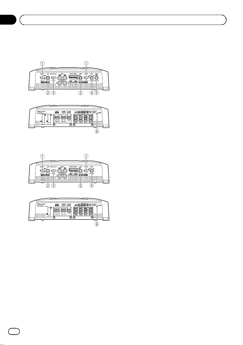
What’s what
GM-A6604
Front side
Rear side
GM-A4604
Front side
Rear side
To adjust the switch, use a flathead screwdriver if needed.
1 LPF (low-pass filter)/HPF (high-pass filter) select switch
Switch the settings based on the connected
speaker.
! When the Subwoofer is connected:
Select LPF. This eliminates high range
frequency and outputs low range frequency.
! When the full range speaker is con-
nected:
Select HPF or OFF. HPF eliminates low
range frequency and output high range
frequency. OFF outputs the entire frequency range.
2 GAIN (gain) control
Adjusting gain controls CHANNEL A (channel A) and CHANNEL B (channel B) helps
align the car stereo output to the Pioneer
amplifier. Default setting is the NORMAL
position.
If output remains low, even when the car
stereo volume is turned up, turn controls to
lower level. If distortion occurs when the car
stereo volume is turned up, turn these controls to higher level.
! If using only one input plug, set the gain
controls for speaker outputs A and B to
the same position.
! For use with an RCA equipped car stereo
(standard output of 500 mV), set to the
NORMAL position. For use with an RCA
equipped Pioneer car stereo, with maximum output of 4 V or more, adjust level
to match that of the car stereo output.
! For use with an RCA equipped car stereo
with output of 4 V, set to the HIGH position.
3 INPUT SELECT (input select) switch
Select 2CH for two-channel input and 4CH
for four–channel input.
! You can select input select only for con-
nections when using the RCA input jack.
For connections when using the speaker
input wire, 4CH will be used automatically no matter which switch setting is
selected.
4 FREQ (cut off frequency) control
Cut off frequency selectable from 40 Hz to
500 Hz if the LPF/HPF select switch is set to
LPF or HPF.
! You can select cut off frequency only for
CHANNEL B.
5 BASS BOOST (bass boost level control)
switch
You can select a bass boost level from 0 dB
to 12 dB.
4
En
Page 5
Setting the unit
Section
02
! Bass boost level setting applies only to
CHANNEL B (channel B) output.
6 Power indicator
The power indicator lights up to indicate
power ON.
Setting gain properly
! Protective function included to prevent
malfunction of the unit and/or speakers
due to excessive output, improper use or
improper connection.
! When outputting high volume sound etc.,
this function cuts off the output for a few
seconds as a normal function, but output
is restored when the volume of the head
unit is turned down.
! A cut in sound output may indicate impro-
per setting of the gain control. To ensure
continuous sound output with the head
unit at a high volume, set amplifier gain
control to a level appropriate for the preout
maximum output level of the head unit, so
that volume can remain unchanged and to
control excess output.
! Despite correct volume and gain settings,
the unit sound still cuts out periodically. In
such cases, please contact the nearest
authorized Pioneer Service Station.
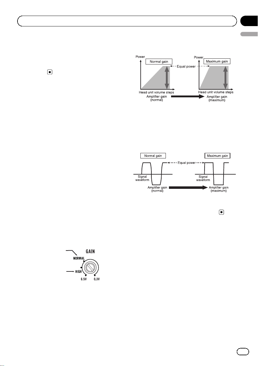
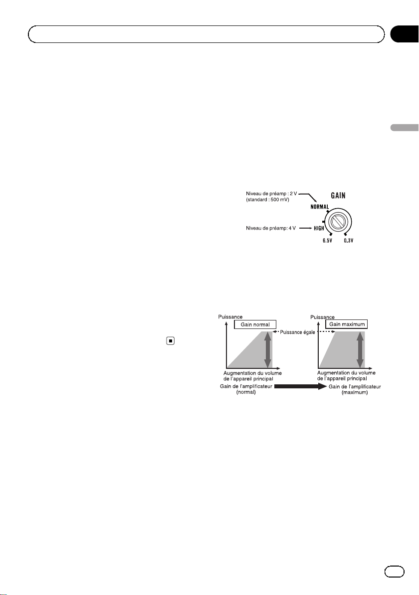
Relationship between amplifier gain
English
and head unit output power
If amplifier gain is raised improperly, this will
simply increase distortion, with little increase
in power.
Signal waveform when outputting at
high volume using amplifier gain
control
If the signal waveform is distorted due to high
output, even if the amplifier gain is raised, the
output power will change only slightly.
Gain control of this unit
Preout level: 2 V
(Standard: 500 mV)
Preout level: 4 V
Above illustration shows NORMAL gain setting.
En
5
Page 6
Section
03
Connecting the units
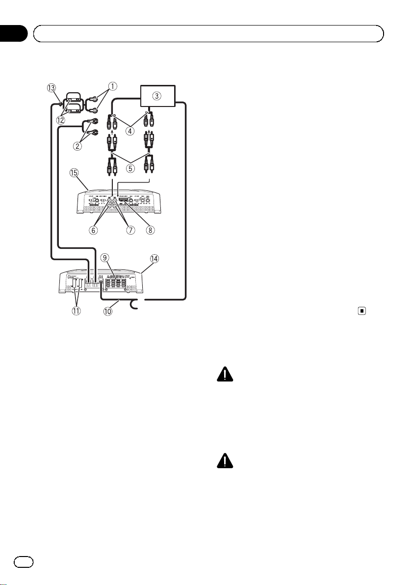
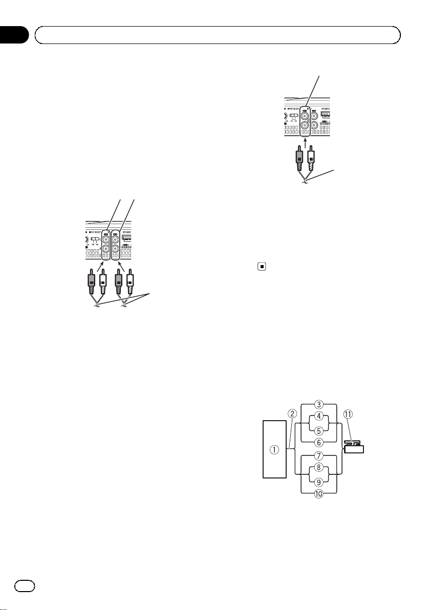
Connection diagram
1 Special red battery wire
RD-223 (sold separately)
After completing all other amplifier connections, finally connect the battery wire terminal
of the amplifier to the positive + battery terminal.
2 Ground wire (Black)
RD-223 (sold separately)
Connect to metal body or chassis.
3 Car stereo with RCA output jacks (sold sepa-
rately)
4 External output
If only one input plug is used, do not connect
anything to RCA input jack B.
5 Connecting wire with RCA pin plugs (sold se-
parately)
6 RCA input jack A
7 RCA input jack B
8 Speaker input terminal (use a connector in-
cluded)
Please see the following section for speaker
connection instructions. Refer to Connections
when using the speaker input wire on page 9.
9 Speaker output terminals
Please see the following section for speaker
connection instructions. Refer to Connections
when using the speaker input wire on page 9.
a System remote control wire (sold separately)
Connect male terminal of this wire to the system remote control terminal of the car stereo.
The female terminal can be connected to the
auto-antenna relay control terminal. If the car
stereo lacks a system remote control terminal,
connect the male terminal to the power terminal via the ignition switch.
b Fuse 25 A × 2 (GM-A6604) / 30 A × 1 (GM-
A4604)
c Fuse (30 A) × 2
d Grommet
e Rear side
f Front side
Note
INPUT SELECT (input select) switch must be set.
For details, see Setting the unit on page 4.
Before connecting the
amplifier
WARNING
! Secure the wiring with cable clamps or adhe-
sive tape. To protect the wiring, wrap sections
in contact with metal parts in adhesive tape.
! Never cut the insulation of the power supply
to feed power to other equipment. Current capacity of the wire is limited.
CAUTION
! Never shorten any wires, the protection circuit
may malfunction.
! Never wire the speaker negative cable directly
to ground.
! Never band together multiple speaker’s nega-
tive cables.
6
En
Page 7
Connecting the units
Section
03
! If the system remote control wire of the ampli-
fier is connected to the power terminal via the
ignition switch (12 V DC), the amplifier will remain on with the ignition whether the car
stereo is on or off, which may exhaust battery
if the engine is at rest or idling.
! Install and route the separately sold battery
wire as far as possible from the speaker wires.
Install and route the separately sold battery
wire, ground wire, speaker wires and the amplifier as far away as possible from the antenna, antenna cable and tuner.
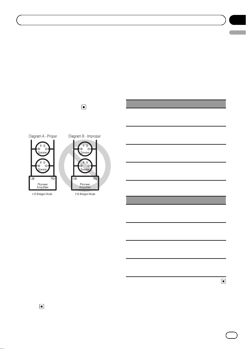
About bridged mode
! Do not install or use this amplifier by wiring
speakers rated at 4W (or lower) in parallel to
achieve a 2 W (or lower) bridged mode (Diagram B).
Amplifier damage, smoke, and overheating
could result from improper bridging. The amplifier surface could also become hot to the
touch and minor burns could result.
To properly install or use a bridged mode and
achieve a 4 W load, wire two 8 W speakers in
parallel with Left + and Right * (Diagram A)
or use a single 4 W speaker.
In addition, refer to the speaker instruction
manual for information on the correct connection procedure.
! For any further enquiries, contact your local
authorized Pioneer dealer or customer
service.
About suitable
specification of speaker
Ensure speakers conform to the following
standards, otherwise there is a risk of fire,
smoke or damage. Speaker impedance is 2 W
to 8 W,or4W to 8 W for two-channel and other
bridge connections.
Subwoofer
Speaker channel Power
Four-channel output
Two-channel output
Three-channel
Speaker output A
Three-channel
Speaker output B
Other than subwoofer
Speaker channel Power
Four-channel output
Two-channel output
Three-channel
Speaker output A
Three-channel
Speaker output B
Nominal input:
Min. 60 W (GM-A6604)
Min. 40 W (GM-A4604)
Nominal input:
Min. 180 W (GM-A6604)
Min. 120 W (GM-A4604)
Nominal input:
Min. 60 W (GM-A6604)
Min. 40 W (GM-A4604)
Nominal input:
Min. 180 W (GM-A6604)
Min. 120 W (GM-A4604)
Max. input:
Min. 120 W (GM-A6604)
Min. 80 W (GM-A4604)
Max. input:
Min. 360 W (GM-A6604)
Min. 240 W (GM-A4604)
Max. input:
Min. 120 W (GM-A6604)
Min. 80 W (GM-A4604)
Max. input:
Min. 360 W (GM-A6604)
Min. 240 W (GM-A4604)
English
En
7
Page 8
Section
03
Connecting the units
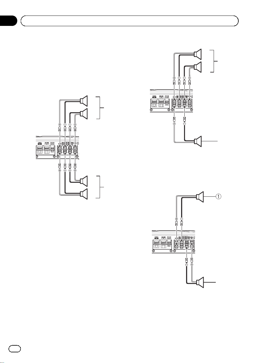
Connecting the speakers
The speaker output mode can be four-channel,
three-channel (stereo and mono) or two-channel (stereo or mono). Connect the speaker
leads based on the mode and the figures
shown below.
Four-channel output
1
3
2
2
4
1
1 Right
2 Left
3 Speaker out A
4 Speaker out B
Three-channel output
1
3
2
4
1 Right
2 Left
3 Speaker out A
4 Speaker out B (Mono)
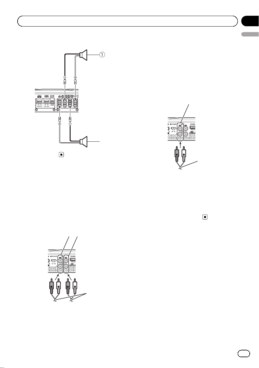
Two-channel output (Stereo)
2
1 Speaker (Right)
2 Speaker (Left)
8
En
Page 9
4
3
Connecting the units
Section
03
Two-channel output (Mono)
1
1 Speaker (Mono)
Connections when using
the RCA input jack
Connect the car stereo RCA output jack and
the RCA input jack of the amplifier.
Four-channel / Three-channel output
! Slide INPUT SELECT (input select) switch
to 4CH position.
4 From car stereo (RCA output)
English
If only one input plug is used, e.g. when the
car stereo has only one output (RCA output),
connect the plug to RCA input jack A rather
than B.
Two-channel output (Stereo) / (Mono)
! Slide INPUT SELECT (input select) switch
to 2CH position.
1
2
1 RCA input jack A
For two-channel output, connect the RCA
plugs to the RCA input jack A.
2 Connecting wire with RCA pin plugs (sold se-
parately)
3 From car stereo (RCA output)
12
3
1 RCA input jack A
2 RCA input jack B
3 Connecting wires with RCA plugs (sold sepa-
rately)
Connections when using
the speaker input wire
Connect the car stereo speaker output wires
to the amplifier using the supplied speaker
input wire.
! Do not connect both the RCA input and the
speaker input at the same time.
En
9
Page 10
Section
03
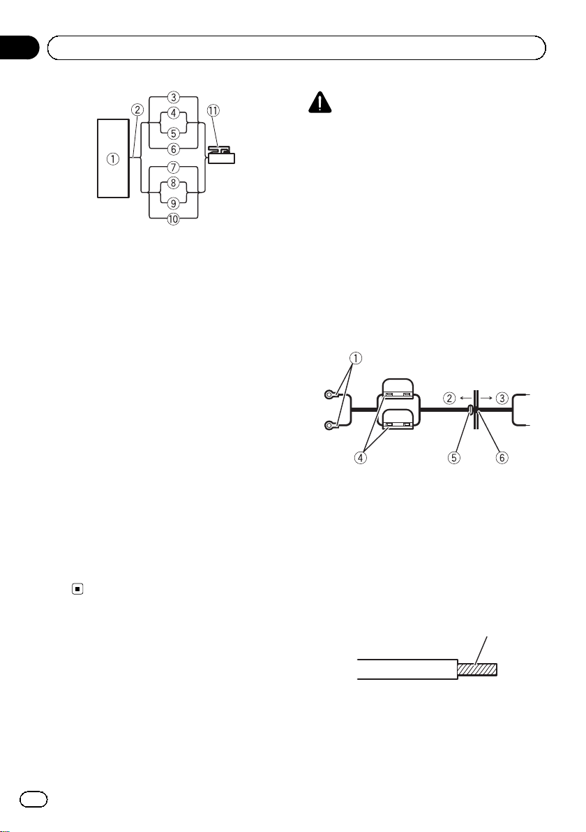
Connecting the units
1 Car Stereo
2 Speaker output
3 White/black: CH A, Left *
4 White: CH A, Left +
5 Gray/black: CH A, Right *
6 Gray: CH A, Right +
7 Green/black: CH B, Left *
8 Green: CH B, Left +
9 Violet/black: CH B, Right *
a Violet: CH B, Right +
b Speaker input connector
To speaker input terminal of this unit.
Note
If speaker input wires from a headunit are connected to this amplifier, the amplifier will automatically turn on when the headunit is turned on.
When the headunit is turned off, the amplifier
turns off automatically. This function may not
work with some headunits. In such cases, please
use a system remote control wire (sold separately). If multiple amplifiers are to be connected
together synchronously, connect the head unit
and all amplifiers via the system remote control
wire.
Connecting the power
terminal
The use of a special red battery and ground
wire RD-223 (sold separately) is recommended. Connect the battery wire directly to
the car battery positive terminal + and the
ground wire to the car body.
WARNING
If the battery wire is not securely fixed to the terminal using the terminal screws, there is a risk of
overheating, malfunction and injury, including
minor burns.
1 Route battery wire from engine compartment to the vehicle interior.
! When drilling a cable pass-hole into the ve-
hicle body and routing a battery wire thorough it, take care not to short-circuit the
wire damaging it by the cut edges or burrs
of the hole.
After completing all other amplifier connections, finally connect the battery wire terminal
of the amplifier to the positive + battery terminal.
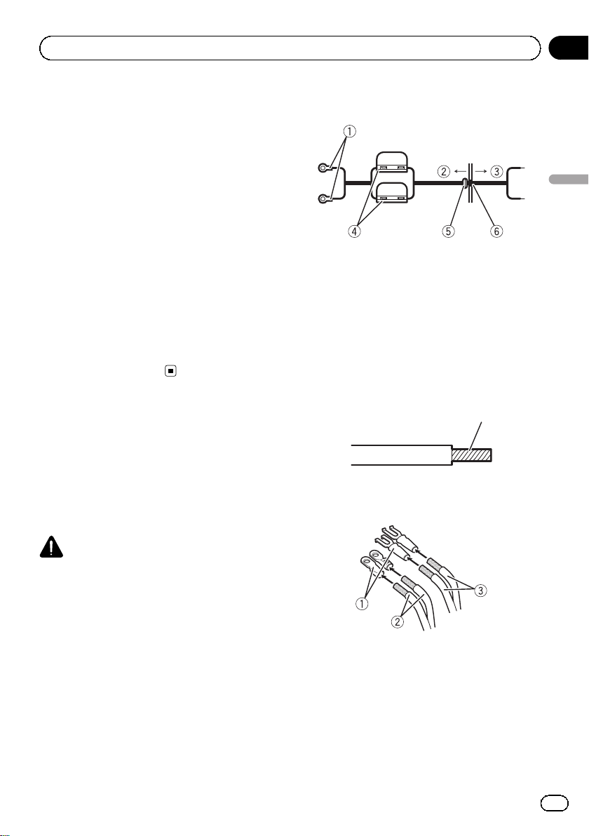
1 Positive + terminal
2 Engine compartment
3 Vehicle interior
4 Fuse (30 A) × 2
5 Insert the O-ring rubber grommet into the
vehicle body.
6 Drill a 14 mm hole into the vehicle body.
2 Twist the battery wire, ground wire
and system remote control wire.
Twist
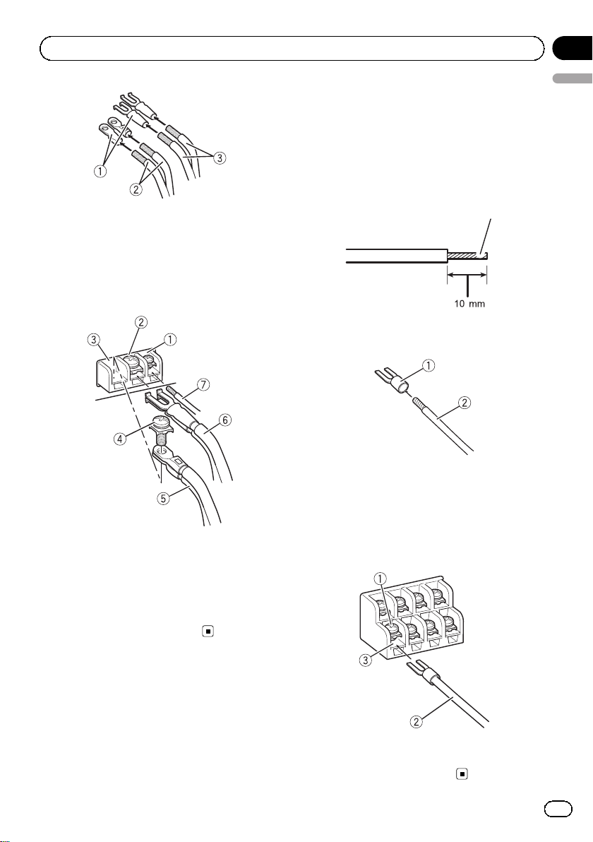
3 Attach lugs to wire ends.
Use pliers, etc., to crimp lugs to wires.
10
En
Page 11
Connecting the units
1 Lug (sold separately)
2 Battery wire
3 Ground wire
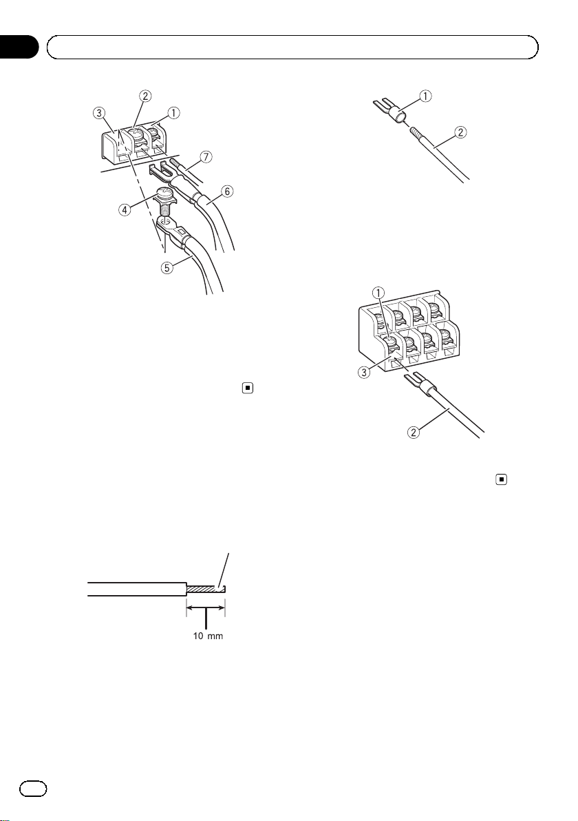
4 Connect the wires to the terminal.
Fix the wires securely with the terminal
screws.
Section
03
English
Connecting the speaker
output terminals
1 Use wire cutters or a utility knife to
strip the end of the speaker wires to expose about 10 mm of wire and then twist
the wire.
Twist
2 Attach lugs to wire ends.
Use pliers, etc., to crimp lugs to wires.
1 System remote control terminal
2 Ground terminal
3 Power terminal
4 Terminal screws
5 Battery wire
6 Ground wire
7 System remote control wire
1 Lug (sold separately)
2 Speaker wire
3 Connect the speaker wires to the
speaker output terminals.
Fix the speaker wires securely with the terminal screws.
1 Terminal screws
2 Speaker wires
3 Speaker output terminals
En
11
Page 12
5
Section
04
Installation
Before installing the amplifier
WARNING
! To ensure proper installation, use the supplied
parts in the manner specified. If any parts
other than those supplied are used, they may
damage internal parts of the amplifier, or become loose causing the amplifier to shut
down.
! Do not install in:
— Places where it could injure the driver or
passengers if the vehicle stops suddenly.
— Places where it may interfere with the dri-
ver, such as on the floor in front of the driver’s seat.
! Install tapping screws in such a way that the
screw tip does not touch any wire. This is important to prevent wires from being cut by vibration of the car, which can result in fire.
! Make sure that wires do not get caught in the
sliding mechanism of the seats or touch the
legs of a person in the vehicle as short-circuit
may result.
! When drilling to install the amplifier, always
confirm no parts are behind the panel and
protect all cables and important equipment
(e.g. fuel/brake lines, wiring) from damage.
CAUTION
! To ensure proper heat dissipation of the ampli-
fier, ensure the following during installation:
— Allow adequate space above the amplifier
for proper ventilation.
— Do not cover the amplifier with a floor mat
or carpet.
! Protection function may activate to protect the
amplifier against overheating due to installation in locations where sufficient heat cannot
be dissipated, continuous use under high-volume conditions, etc. In such cases, the amplifier reduces the power output or shuts
down until it has cooled to a certain designated temperature.
! Place all cables away from hot places, such
as near the heater outlet.
! The optimal installation location differs de-
pending on the car model. Secure the amplifier at a sufficiently rigid location.
! Check all connections and systems before
final installation.
! After installing the amplifier, confirm that the
spare tire, jack and tools can be easily removed.
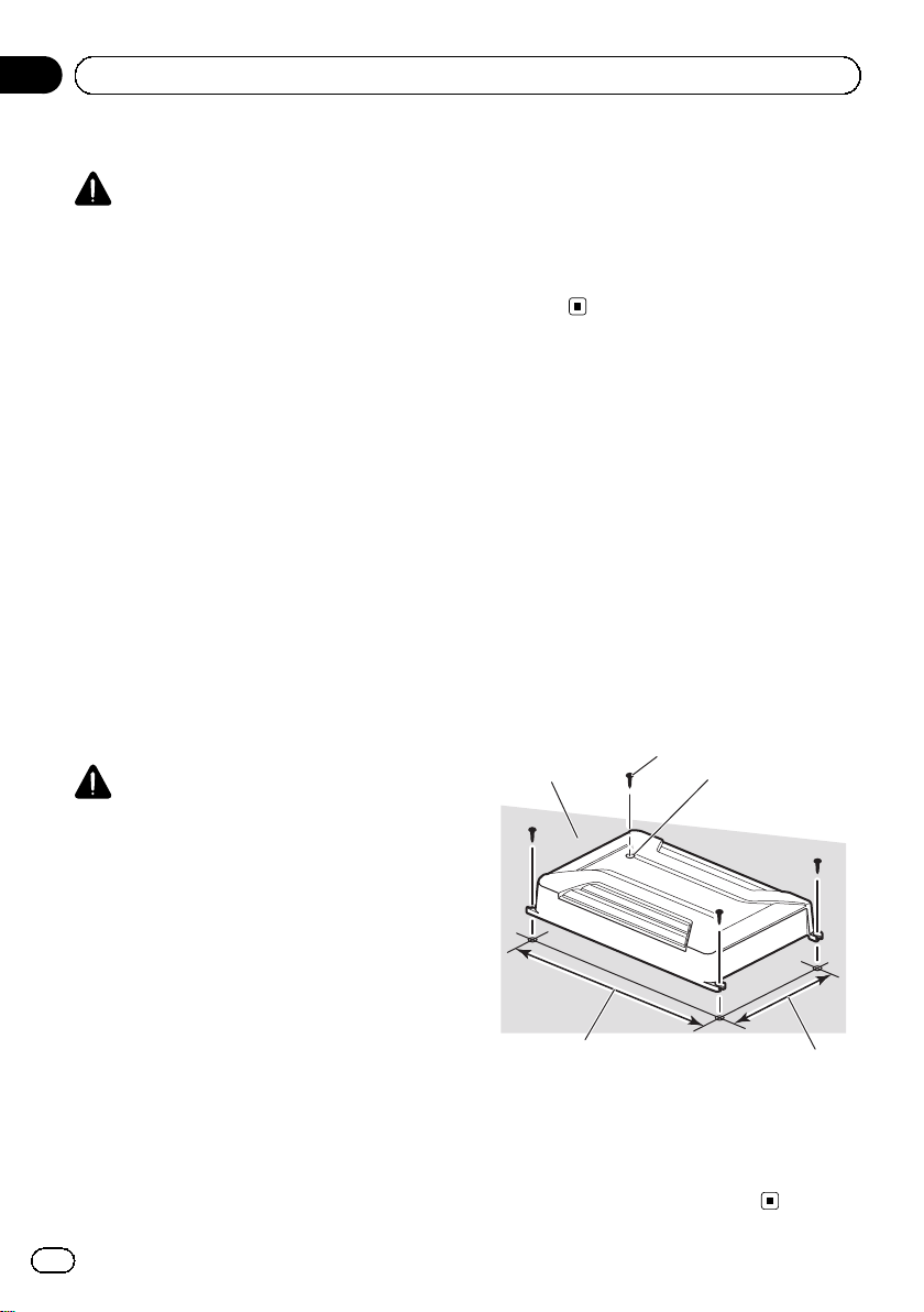
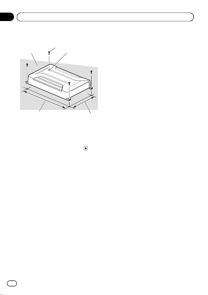
Example of installation on
the floor mat or chassis
1 Place the amplifier in the desired installation location.
Insert the supplied tapping screws (4 mm ×
18 mm) into the screw holes and push on the
screws with a screwdriver so they make an imprint where the installation holes are to be located.
2 Drill 2.5 mm diameter holes at the imprints either on the carpet or directly on
the chassis.
3 Install the amplifier with the use of
supplied tapping screws (4 mm × 18 mm).
1
3
4
1 Tapping-screws (4 mm × 18 mm)
2 Drill a 2.5 mm diameter hole
3 Floor mat or chassis
4 Hole-to-hole distance: 338 mm (GM-A6604) /
308 mm (GM-A4604)
5 Hole-to-hole distance: 196 mm
2
12
En
Page 13

Additional information
Appendix
Specifications
GM-A6604
Power source ............................. 14.4 V DC (10.8 V to 15.1 V
allowable)
Grounding system ................... Negative type
Current consumption ............ 31 A (at continuous power,
4 W)
Average current drawn ......... 8.5 A (4 W for four channels)
14 A (4 W for two channels)
Fuse ................................................ 25 A × 2
Dimensions (W × H × D) ... 348 mm × 60 mm ×
215 mm
Weight .......................................... 2.3 kg (Leads for wiring not
included)
Maximum power output ....... 120 W × 4 (4 W) / 190W × 4
(2 W) / 760 W TOTAL
(BRIDGE)
Continuous power output ... 60 W × 4 (at 14.4 V, 4 W,
20 Hz to 20 kHz ≦ 1 % THD
+N)
180 W × 2 (at 14.4 V, 4 W
BRIDGE 1 kHz, ≦ 1 % THD
+N)
90 W × 4 (at 14.4 V, 2 W,
1 kHz, ≦ 1 % THD+N)
Load impedance ...................... 4 W (2 W to 8 W allowable)
Frequency response ............... 10 Hz to 70 kHz (+0 dB,
–3 dB)
Signal-to-noise ratio ............... 95 dB (IEC-A network)
Distortion ..................................... 0.05 % (10 W, 1 kHz)
Low pass filter:
(A ch)
Cut off frequency ........... 80 Hz
Cut off slope ..................... –12 dB/oct
(B ch)
Cut off frequency ........... 40 Hz to 500Hz
Cut off slope ..................... –12 dB/oct
High pass filter:
(A ch)
Cut off frequency ........... 80 Hz
Cut off slope ..................... –12 dB/oct
(B ch)
Cut off frequency ........... 40 Hz to 500Hz
Cut off slope ..................... –12 dB/oct
Bass boost:
Frequency .......................... 50 Hz
Level ..................................... 0dBto12dB
Gain control:
RCA ...................................... 0.3 V to 6.5 V
Speaker .............................. 3.0 V to 26 V
Maximum input level / impedance:
RCA ...................................... 6.5 V / 22 kW
Speaker .............................. 26 V / 16 kW
GM-A4604
Power source ............................. 14.4 V DC (10.8 V to 15.1 V
allowable)
Grounding system ................... Negative type
Current consumption ............ 20.5 A (at continuous power,
4 W)
Average current drawn ......... 5.5 A (4W for four channels)
8.5 A (4 W for two channels)
Fuse ................................................ 30 A × 1
Dimensions (W × H × D) ... 318 mm × 60 mm ×
215 mm
Weight .......................................... 2.1 kg (Leads for wiring not
included)
Maximum power output ....... 80 W × 4 (4 W ) / 120 W × 4
(2 W) / 480 W TOTAL
(BRIDGE)
Continuous power output ... 40 W × 4 (at 14.4 V, 4 W,
20 Hz to 20 kHz ≦ 1 % THD
+N)
120 W × 2 (at 14.4 V, 4 W
BRIDGE 1 kHz, ≦ 1 % THD
+N)
60 W × 4 (at 14.4 V, 2 W,
1 kHz, ≦ 1 % THD+N)
Load impedance ...................... 4 W (2 W to 8 W allowable)
Frequency response ............... 10 Hz to 70 Hz (+0 dB,
–3 dB)
Signal-to-noise ratio ............... 94 dB (IEC-A network)
Distortion ..................................... 0.05 % (10 W, 1 kHz)
Low pass filter:
(A ch)
Cut off frequency ........... 80 Hz
Cut off slope ..................... –12 dB/oct
(B ch)
Cut off frequency ........... 40 Hz to 500Hz
Cut off slope ..................... –12 dB/oct
High pass filter:
(A ch)
Cut off frequency ........... 80 Hz
Cut off slope ..................... –12 dB/oct
(B ch)
Cut off frequency ........... 40 Hz to 500Hz
Cut off slope ..................... –12 dB/oct
Gain control:
RCA ...................................... 0.3 V to 6.5 V
Speaker .............................. 3.0 V to 26 V
Maximum input level / impedance:
RCA ...................................... 6.5 V / 22 kW
Speaker .............................. 26 V / 16 kW
Notes
! Specifications and the design are subject to
modifications without notice.
! The average current drawn is nearly the maxi-
mum current drawn by this unit when an
audio signal is input. Use this value when
working out total current drawn by multiple
power amplifiers.
English
En
13
Page 14
Section
01
Avant de commencer
Nous vous remercions d’avoir acheté cet
appareil PIONEER
Pour garantir une utilisation correcte, lisez
bien ce mode d’emploi avant d’utiliser cet appareil. Il est particulièrement important que
vous lisiez et respectiez les indications AT-
TENTION et PRÉCAUTION de ce mode
d’emploi. Conservez-le dans un endroit sûr et
facilement accessible pour toute consultation
ultérieure.
Si vous souhaitez vous débarrasser de cet appareil, ne le mettez pas à la poubelle avec vos
ordures ménagères. Il existe un système de
collecte séparé pour les appareils électroniques usagés, qui doivent être récupérés, traités
et recyclés conformément à la législation.
Dans les états membres de l’UE, en Suisse et
en Norvège, les foyers domestiques peuvent
rapporter leurs produits électroniques usagés
gratuitement à des points de collecte spécifiés
ou à un revendeur (sous réserve d’achat d’un
produit similaire).
Dans les pays qui ne sont pas mentionnés cidessus, veuillez contacter les autorités locales
pour vous informer de la méthode correcte de
mise au rebut.
En agissant ainsi vous assurerez que le produit que vous mettez au rebut est soumis au
processus de traitement, de récupération et
de recyclage nécessaire et éviterez ainsi les effets négatifs potentiels sur l’environnement et
la santé publique.
Visitez notre site Web
Rendez-nous visite sur le site suivant :
http://www.pioneer.fr
! Enregistrez votre produit. Nous conserve-
rons les détails de votre achat dans nos fichiers pour vous aider à faire référence à
ces informations pour une déclaration d’assurance en cas de perte ou de vol.
! Notre site Web fournit les informations les
plus récentes sur PIONEER
CORPORATION.
Si vous rencontrez des
problèmes
En cas d’anomalie, consultez le distributeur
ou le service d’entretien agréé par Pioneer le
plus proche.
Avant de connecter/
d’installer l’amplificateur
ATTENTION
! L’utilisation d’un fil de terre RD-223 et d’un fil
de batterie rouge spécial, disponibles séparément, est recommandée. Connectez le fil de la
batterie directement sur la borne positive +
de la batterie du véhicule et le fil de terre sur
la carrosserie du véhicule.
! Cet appareil est utilisable sur des véhicules
équipés d’une batterie 12 V avec mise à la
masse du négatif. Vérifiez la tension de la batterie avant l’installation dans des véhicules de
caravaning, des camions ou des bus.
! Lors de l’installation de cet appareil, veillez à
connecter d’abord le fil de masse. Assurezvous que le fil de masse est connecté correctement aux parties métalliques de la carrosserie du véhicule. Le fil de masse de cet appareil
doit être connecté indépendamment au véhicule à l’aide de vis différentes. Si la vis du fil
de masse se desserre ou tombe, il peut en résulter un incendie, de la fumée ou un dysfonctionnement.
14
Fr
Page 15

Avant de commencer
Section
01
! Utilisez toujours un fusible correspondant aux
caractéristiques spécifiées. L’utilisation d’un
fusible incorrect peut entraîner une surchauffe et de la fumée, des dommages au niveau du produit et des blessures, incluant des
brûlures.
! Vérifiez les connexions de l’alimentation et
des haut-parleurs en cas de rupture du fusible
du fil de batterie vendu séparément ou de
l’amplificateur. Déterminez la cause et résolvez le problème, puis remplacez le fusible par
un fusible identique.
! Installez toujours l’amplificateur sur une sur-
face plane. N’installez pas l’amplificateur sur
une surface qui n’est pas plane ou sur une
surface présentant une saillie. Ceci pourrait
entraîner un dysfonctionnement.
! Lors de l’installation de l’amplificateur, ne lais-
sez pas des pièces telles que des vis supplémentaires se coincer entre l’amplificateur et
l’automobile. Ceci pourrait entraîner un dysfonctionnement.
! Ne laissez pas cet appareil entrer en contact
avec des liquides. Cela pourrait provoquer une
électrocution. Tout contact avec des liquides
pourrait aussi provoquer des dommages, de
la fumée et une surchauffe de l’appareil.
Les surfaces de l’amplificateur et des hautparleurs connectés peuvent également chauffer et entraîner des brûlures mineures.
! En cas d’événement anormal, l’alimentation
de l’amplificateur est coupée de manière à éviter tout dysfonctionnement de l’équipement.
Dans ce cas, coupez l’alimentation du système et vérifiez les connexions de l’alimentation et des haut-parleurs. Si vous n’êtes pas
en mesure de déterminer la cause, veuillez
contacter votre revendeur.
! Déconnectez toujours la borne négative * de
la batterie préalablement, de manière à éviter
tout risque de choc électrique ou de court-circuit lors de l’installation.
! N’essayez pas de démontez ou de modifiez
cet appareil. Ceci pourrait provoquer un incendie, une électrocution ou tout autre dysfonctionnement.
PRÉCAUTION
! Maintenez le niveau d’écoute à une valeur
telle que vous puissiez entendre les sons provenant de l’extérieur.
! L’utilisation prolongée du système stéréo du
véhicule lorsque le moteur est à l’arrêt ou au
ralenti peut épuiser la batterie.
Quelques mots sur la fonction de
protection
Ce produit est doté d’une fonction de protection.
Lorsque ce produit détecte une anomalie, les
fonctions suivantes permettent de protéger le
produit et la sortie du haut-parleur.
! L’indicateur de mise sous tension s’éteint et
l’amplificateur se mettra hors service dans les
situations indiquées ci-dessous.
— Si la borne de sortie des haut-parleurs et le
fil du haut-parleur sont en court-circuit.
— Si une tension CC est appliquée à la borne
de sortie des haut-parleurs.
! L’amplificateur réduira la puissance de sortie
si la température à l’intérieur de l’amplificateur est élevée. Si la température est trop élevée, l’indicateur de mise sous tension s’éteint
et l’amplificateur se met hors service.
Français
15
Fr
Page 16
Section
02
Réglage de l’appareil
Description de l’appareil
GM-A6604
Face avant
Face arrière
GM-A4604
Face avant
Face arrière
Si nécessaire, utilisez un tournevis plat pour
régler le commutateur.
1 Commutateur de sélection LPF (filtre
passe-bas)/HPF (filtre passe-haut)
Basculez les réglages en fonction du hautparleur connecté.
! Lorsque le haut-parleur d’extrêmes gra-
ves est connecté :
Sélectionnez LPF. Cela supprime les fréquences élevées et émet à basse fréquence.
! Lorsque le haut-parleur pleine gamme
est connecté :
Sélectionnez HPF ou OFF. HPF supprime
les basses fréquences et émet à haute
fréquence. OFF émet la gamme de fréquences complète.
2 Commande GAIN (gain)
Le réglage des commandes de gain
CHANNEL A (canal A) et CHANNEL B
(canal B) aide à aligner la sortie stéréo du
véhicule sur l’amplificateur Pioneer. Le ré-
glage par défaut est la position NORMAL.
Si la sortie reste faible alors que le volume
du système stéréo du véhicule a été aug-
menté, tournez les commandes vers un ni-
veau plus faible. En cas de distorsion lors
de l’augmentation du volume du système
stéréo du véhicule, tournez les commandes
vers un niveau plus élevé.
! Si vous n’utilisez qu’une seule prise d’en-
trée, réglez les commandes de gain des
sorties de haut-parleurs A et B sur la
même position.
! Procédez au réglage sur la position
NORMAL pour l’utilisation avec un sys-
tème stéréo de véhicule équipé d’une
sortie RCA (sortie standard de 500 mV).
Pour l’utilisation avec un système stéréo
de véhicule Pioneer équipé d’une sortie
RCA, dont la sortie maximale est de 4 V
ou plus, réglez le niveau en fonction de
celui de sortie du système stéréo du véhicule.
! Procédez au réglage sur la position
HIGH pour l’utilisation avec un système
stéréo de véhicule équipé d’une sortie de
4V.
3 Commutateur INPUT SELECT (sélection
de l’entrée)
Sélectionnez 2CH pour l’entrée deux canaux
et 4CH pour l’entrée quatre canaux.
16
Fr
Page 17
Réglage de l’appareil
Section
02
! Vous pouvez choisir la sélection de l’en-
trée uniquement pour les connexions
lors de l’utilisation du jack d’entrée RCA.
Pour les connexions lors de l’utilisation
du fil d’entrée des haut-parleurs, le réglage 4CH sera automatiquement utilisé
quel que soit le réglage du commutateur.
4 Commande FREQ (fréquence de coupure)
La fréquence de coupure pouvant être sélectionnée est de 40 Hz à 500 Hz si le commutateur de sélection LPF/HPF est réglé sur
LPF ou HPF.
! Vous pouvez sélectionner la fréquence
de coupure pour CHANNEL B.
5 Commutateur BASS BOOST (commande
du niveau d’accentuation des graves)
Vous pouvez sélectionner le niveau d’accentuation des graves de 0 dB à 12 dB.
! Le réglage du niveau d’accentuation des
graves ne s’applique qu’à la sortie
CHANNEL B (canal B).
6 Indicateur de mise sous tension
L’indicateur de mise sous tension s’allume
pour indiquer la mise sous tension.
au niveau de sortie maximal de la sortie
préamp de l’appareil central de manière à
ce que le volume ne nécessite aucune modification et à ce que les sorties excessives
soient contrôlées.
! Le son de l’appareil est régulièrement
coupé alors que les réglages du gain et du
volume sont corrects. Dans de tels cas,
veuillez contacter le Centre d’entretien
agréé par Pioneer le plus proche.
Commande de gain de l’appareil
L’illustration ci-dessus représente le réglage
de gain NORMAL.
Relation entre le gain de
l’amplificateur et la puissance de
sortie de l’appareil central
Français
Réglage correct du gain
! Fonction de protection incluse pour éviter
tout dysfonctionnement de l’appareil et/ou
des haut-parleurs lié à une sortie excessive
ou à une utilisation ou une connexion incorrecte.
! Lors de l’émission de sons à haut volume,
etc., cette fonction coupe l’émission pendant quelques secondes. L’émission est ce-
pendant rétablie une fois le volume de
l’appareil central baissé.
! Une coupure de la sortie son peut indiquer
un réglage incorrect de la commande de
gain. Afin de garantir une émission sonore
continue lorsque le volume de l’appareil
central est élevé, réglez la commande de
gain de l’amplificateur à un niveau adapté
Si le gain de l’amplificateur est augmenté de
manière incorrecte, les distorsions augmentent sans que la puissance soit beaucoup plus
importante.
Fr
17
Page 18
Section
02
Réglage de l’appareil
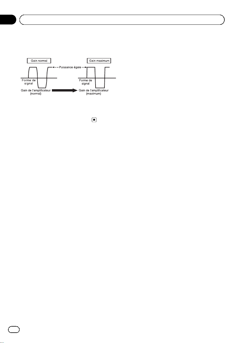
Forme de signal lors de l’émission à
volume élevé avec la commande de
gain de l’amplificateur
Si la forme de signal est distordue à cause
d’une sortie élevée, la puissance de sortie ne
sera que légèrement modifiée même en augmentant le gain de l’amplificateur.
18
Fr
Page 19
Connexion des appareils
Section
03
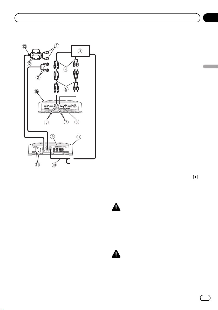
Schéma de connexion
1 Fil de batterie rouge spécial
RD-223 (vendu séparément)
Une fois toutes les autres connexions de l’amplificateur effectuées, connectez la borne du
fil de batterie de l’amplificateur à la borne positive + de la batterie.
2 Fil de terre (noir)
RD-223 (vendu séparément)
À connecter au châssis ou à la carrosserie en
métal.
3 Système stéréo de véhicule avec jacks de sor-
tie RCA (vendu séparément)
4 Sortie externe
Si une seule prise d’entrée est utilisée, ne
connectez rien au jack d’entrée RCA B.
5 Fil de connexion avec prises RCA (vendu sépa-
rément)
6 Jack d’entrée RCA A
7 Jack d’entrée RCA B
8 Borne d’entrée des haut-parleurs (utilisez un
connecteur fourni)
Veuillez vous reporter à la section suivante
pour les instructions de connexion des haut-
parleurs. Reportez-vous à la page 22, Conne-
xions lors de l’utilisation du fil d’entrée des
haut-parleurs.
9 Bornes de sortie des haut-parleurs
Veuillez vous reporter à la section suivante
pour les instructions de connexion des hautparleurs. Reportez-vous à la page 22, Conne-
xions lors de l’utilisation du fil d’entrée des
haut-parleurs.
a Fil de la télécommande du système (vendu sé-
parément)
Connectez la borne mâle du fil à la borne de
la télécommande du système stéréo du véhicule. La borne femelle peut être connectée à
la prise de commande du relais de l’antenne
motorisée. Si le système stéréo du véhicule ne
dispose pas d’une borne de télécommande,
connectez la borne mâle à la borne d’alimentation via le contact d’allumage.
b Fusible 25 A × 2 (GM-A6604) / 30 A × 1 (GM-
A4604)
c Fusible (30 A) × 2
d Rondelle
e Face arrière
f Face avant
Remarque
Le commutateur INPUT SELECT (sélection de
l’entrée) doit être réglé. Pour plus de détails, reportez-vous à la page 16, Réglage de l’appareil.
Avant de connecter
l’amplificateur
ATTENTION
! Fixez le câblage avec des serre-fils ou de la
bande adhésive. Pour protéger le câblage, enroulez les sections en contact avec des pièces
en métal dans du ruban adhésif.
! Ne découpez jamais l’isolation de l’alimenta-
tion pour alimenter d’autres équipements. La
capacité en courant du fil est limitée.
PRÉCAUTION
! Ne raccourcissez jamais aucun fil, faute de
quoi le circuit de protection risque de fonctionner de manière incorrecte.
! Ne câblez jamais le câble négatif du haut-par-
leur directement à la masse.
Français
19
Fr
Page 20
Section
03
Connexion des appareils
! Ne réunissez jamais ensemble les câbles né-
gatifs de plusieurs haut-parleurs.
! Si le fil de la télécommande du système de
l’amplificateur est connecté à la borne d’alimentation via le contact d’allumage (12 VCC),
l’amplificateur reste sous tension que le système stéréo du véhicule soit allumé ou non,
ce qui peut épuiser la batterie lorsque le moteur est à l’arrêt ou au ralenti.
! Installez et positionnez le fil de batterie vendu
séparément aussi loin que possible des fils de
haut-parleurs.
Installez et positionnez le fil de batterie vendu
séparément, le fil de terre, les fils de haut-parleurs et l’amplificateur aussi loin que possible
de l’antenne, du câble d’antenne et du
syntoniseur.
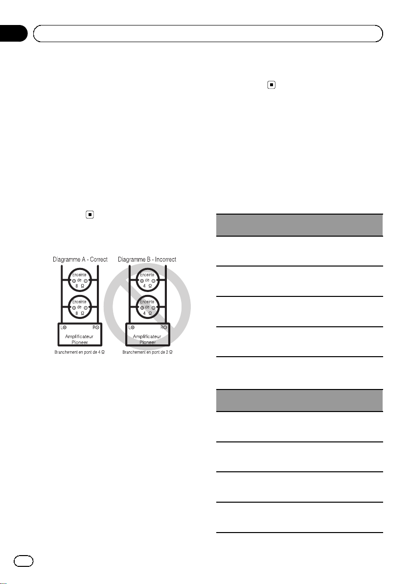
À propos du mode ponté
! N’installez ni n’utilisez cet amplificateur en
branchant des haut-parleurs de 4 W (ou inférieur) en parallèle afin d’obtenir un mode
ponté de 2 W (ou inférieur) (DiagrammeB).
Un pontage inapproprié pourrait provoquer
des dommages, de la fumée et une surchauffe
de l’amplificateur. La surface de l’amplificateur pourrait également devenir chaude et
provoquer ainsi des brûlures mineures.
Pour installer ou utiliser un mode ponté de
manière appropriée et obtenir une charge de
4 W, branchez deux haut-parleurs de 8W en parallèle via + (gauche) et * (droite) (Diagramme A) ou n’utilisez qu’un seul haut-parleur de
4 W.
Reportez-vous également au mode d’emploi
du haut-parleur pour plus d’informations sur
la procédure de connexion appropriée.
! Pour toute autre requête, veuillez contacter le
service clientèle ou votre revendeur Pioneer
agréé local.
À propos de la spécification
adaptée des haut-parleurs
Vérifiez que les haut-parleurs sont conformes
aux normes suivantes, faute de quoi ils présenteront un risque d’incendie, de fumée ou
de dommages. L’impédance des haut-parleurs
est de 2 W à8W ou de 4 W à8W pour les
connexions pontées deux canaux et autres.
Haut-parleur d’extrêmes graves
Canal du haut-parleur
Sortie quatre canaux
Sortie deux canaux
Sortie A du haut-parleur trois canaux
Sortie B du haut-parleur trois canaux
Haut-parleur autre que le haut-parleur
d’extrêmes graves
Canal du haut-parleur
Sortie quatre canaux
Sortie deux canaux
Sortie A du haut-parleur trois canaux
Sortie B du haut-parleur trois canaux
Alimentation
Entrée nominale :
60 W min. (GM-A6604)
40 W min. (GM-A4604)
Entrée nominale :
180 W min. (GM-A6604)
120 W min. (GM-A4604)
Entrée nominale :
60 W min. (GM-A6604)
40 W min. (GM-A4604)
Entrée nominale :
180 W min. (GM-A6604)
120 W min. (GM-A4604)
Alimentation
Entrée max. :
120 W min. (GM-A6604)
80 W min. (GM-A4604)
Entrée max. :
360 W min. (GM-A6604)
240 W min. (GM-A4604)
Entrée max. :
120 W min. (GM-A6604)
80 W min. (GM-A4604)
Entrée max. :
360 W min. (GM-A6604)
240 W min. (GM-A4604)
20
Fr
Page 21
Connexion des appareils
Section
03
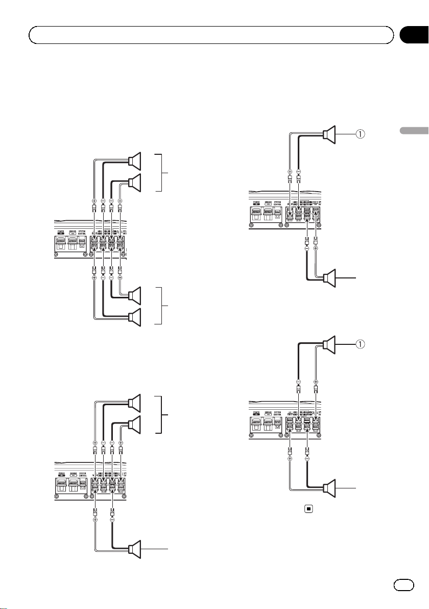
Connexion des haut-parleurs
Le mode de sortie des haut-parleurs peut être
quatre canaux, trois canaux (stéréo et mono)
ou deux canaux (stéréo ou mono). Connectez
les fils des haut-parleurs en fonction du mode
et des illustrations ci-dessous.
Sortie quatre canaux
1
3
2
2
4
1
1 Droite
2 Gauche
3 Sortie A du haut-parleur
4 Sortie B du haut-parleur
Sortie trois canaux
1 Droite
2 Gauche
3 Sortie A du haut-parleur
4 Sortie B du haut-parleur (mono)
Sortie deux canaux (stéréo)
Français
2
1 Haut-parleur (droit)
2 Haut-parleur (gauche)
Sortie deux canaux (mono)
1
2
3
4
1 Haut-parleur (mono)
1
21
Fr
Page 22
4
3
Section
03
Connexion des appareils
Connexions lors de
l’utilisation du jack
d’entrée RCA
Connectez le jack de sortie RCA du système
stéréo du véhicule et le jack d’entrée RCA de
l’amplificateur.
Sortie quatre/trois canaux
! Faites glisser le commutateur
INPUT SELECT (sélection de l’entrée) en
position 4CH.
12
3
1 Jack d’entrée RCA A
2 Jack d’entrée RCA B
3 Fils de connexion avec prises RCA (vendus sé-
parément)
4 Depuis le système stéréo du véhicule (sortie
RCA)
Si une seule prise d’entrée est utilisée
(lorsque le système stéréo du véhicule ne dispose que d’une seule sortie (sortie RCA), par
exemple), connectez la prise sur le jack d’entrée RCA A (plutôt que sur le jack d’entrée
RCA B).
Sortie deux canaux (stéréo)/(mono)
! Faites glisser le commutateur
INPUT SELECT (sélection de l’entrée) en
position 2CH.
1
2
1 Jack d’entrée RCA A
Pour la sortie deux canaux, connectez les prises RCA au jack d’entrée RCA A.
2 Fil de connexion avec prises RCA (vendu sépa-
rément)
3 Depuis le système stéréo du véhicule (sortie
RCA)
Connexions lors de
l’utilisation du fil d’entrée
des haut-parleurs
Connectez les fils de sortie des haut-parleurs
du système stéréo du véhicule à l’amplificateur à l’aide du fil d’entrée des haut-parleurs
fourni.
! Ne connectez pas simultanément l’entrée
RCA et l’entrée des haut-parleurs.
22
1 Système stéréo du véhicule
2 Sortie des haut-parleurs
3 Blanc/noir : Canal A, * gauche
4 Blanc : Canal A, + gauche
5 Gris/noir : Canal A, * droite
6 Gris : Canal A, + droite
Fr
Page 23
Connexion des appareils
Section
03
7 Vert/noir : Canal B, * gauche
8 Vert : Canal B, + gauche
9 Violet/noir : Canal B, * droite
a Violet : Canal B, + droite
b Connecteur d’entrée des haut-parleurs
Vers la borne d’entrée des haut-parleurs de
l’appareil.
Remarque
Si les fils d’entrée des haut-parleurs d’un appareil
central sont connectés à cet amplificateur, l’amplificateur se met automatiquement en service
lorsque l’appareil central est mis en service.
Lorsque l’appareil central est mis hors service,
l’amplificateur se met automatiquement hors service. Cette fonction peut ne pas fonctionner sur
certains appareils centraux. Dans ce cas, utilisez
le fil d’une télécommande du système (vendu séparément). Si plusieurs amplificateurs sont
connectés de manière synchrone, reliez l’appareil
central et tous les amplificateurs via le fil de la télécommande du système.
Connexion de la bor ne
d’alimentation
L’utilisation d’un fil de batterie rouge spécial et
d’un fil de terre RD-223 (vendus séparément)
est recommandée. Connectez le fil de la batterie directement sur la borne positive + de la
batterie du véhicule et le fil de terre sur la carrosserie du véhicule.
fil de batterie de l’amplificateur à la borne positive + de la batterie.
Français
1 Borne positive +
2 Compartiment du moteur
3 Intérieur du véhicule
4 Fusible (30 A) × 2
5 Insérez la rondelle en caoutchouc du joint
torique dans la carrosserie du véhicule.
6 Percez un trou de 14 mm dans la carrosse-
rie du véhicule.
2 Torsadez le fil de la batterie, le fil de
terre et le fil de la télécommande du système.
Torsadez
3 Fixez les cosses aux extrémités des fils.
Utilisez des pinces, etc. pour serrer les cosses
sur les fils.
ATTENTION
Si le fil de la batterie n’est pas fermement fixé à la
borne à l’aide des vis de la borne, des risques de
surchauffe, d’anomalie de fonctionnement et de
blessures, brûlures mineures incluses, existent.
1 Positionnez le fil de la batterie du
compartiment du moteur jusqu’àl’intérieur
du véhicule.
! Lors du perçage d’un trou de passage des
câbles dans la carrosserie du véhicule et le
passage d’un fil de la batterie à travers
celui-ci, veillez à ne pas créer un court-circuit du fil en l’endommageant avec les
bords coupants ou les bavures du trou.
Une fois toutes les autres connexions de l’amplificateur effectuées, connectez la borne du
1 Cosse (vendue séparément)
2 Fil de la batterie
3 Fil de terre
4 Connectez les fils à la borne.
Fixez fermement les fils à l’aide des vis de la
borne.
23
Fr
Page 24
Section
03
Connexion des appareils
1 Cosse (vendue séparément)
2 Fil du haut-parleur
3 Connectez les fils des haut-parleurs aux
bornes de sortie des haut-parleurs.
Fixez fermement les fils des haut-parleurs à
l’aide des vis de la borne.
1 Borne de la télécommande du système
2 Borne de masse
3 Borne d’alimentation
4 Vis de la borne
5 Fil de la batterie
6 Fil de terre
7 Fil de la télécommande du système
Connexion des bornes de
sortie des haut-parleurs
1 Utilisez une pince coupante ou un couteau à lame rétractable pour dénuder l’extrémité des fils des haut-parleurs et
exposer environ 10 mm de fil, puis torsadez
le fil.
Torsadez
2 Fixez les cosses aux extrémités des fils.
Utilisez des pinces, etc. pour serrer les cosses
sur les fils.
24
Fr
1 Vis de la borne
2 Fils des haut-parleurs
3 Bornes de sortie des haut-parleurs
Page 25
Installation
Section
04
Avant d’installer
l’amplificateur
ATTENTION
! Afin de garantir une installation correcte, utili-
sez les pièces fournies de la manière indiquée. Si vous utilisez des pièces autres que
celles fournies, celles-ci risquent d’endommager des pièces internes de l’amplificateur ou
peuvent se desserrer, ce qui entraînerait l’arrêt
de l’amplificateur.
! Ne procédez pas à l’installation dans :
— Des emplacements où l’appareil peut bles-
ser le conducteur ou les passagers en cas
d’arrêt soudain du véhicule.
— Des emplacements où l’appareil peut
gêner le conducteur, tels que sur le sol devant le siège du conducteur.
! Installez les vis autotaraudeuses de telle ma-
nière que la pointe des vis n’entre en contact
avec aucun fil. Cela est important pour éviter
toute coupure des fils par les vibrations du véhicule, ce qui pourrait entraîner un incendie.
! Assurez-vous que les fils ne sont pas coincés
dans le mécanisme coulissant des sièges ou
ne touchent pas les jambes d’un passager,
car cela pourrait entraîner un court-circuit.
! Lorsque vous percez pour installer l’amplifica-
teur, vérifiez toujours qu’il n’y a aucune pièce
derrière le panneau et que tous les câbles et
équipements importants (conduites de carburant/freinage, câblage, par exemple) sont protégés des dommages.
ment dans lequel la chaleur ne peut pas se
dissiper suffisamment, une utilisation continue à un volume élevé, etc. Le cas échéant,
l’amplificateur réduit la puissance de sortie
ou se met hors service jusqu’àcequ’il se soit
refroidi et atteigne une certaine température.
! Placez les câbles à l’écart de tous les endroits
chauds, par exemple les sorties de chauffage.
! L’emplacement d’installation optimal varie en
fonction du modèle de véhicule. Fixez l’amplificateur à un emplacement suffisamment rigide.
! Vérifiez toutes les connexions et tous les systè-
mes avant l’installation finale.
! Une fois l’amplificateur installé, vérifiez que la
roue de secours, le cric et les outils peuvent
facilement être retirés.
Exemple d’installation sur
le tapis de sol ou le châssis
1 Placez l’amplificateur à l’emplacement
d’installation souhaité.
Insérez les vis autotaraudeuses fournies
(4 mm × 18 mm) dans les trous pour vis et appuyez sur les vis à l’aide d’un tournevis de manière créer une empreinte de l’emplacement
des trous d’installation.
2 Percez des trous de 2,5 mm de diamètre
au niveau des empreintes, sur le sol ou directement sur le châssis.
Français
PRÉCAUTION
! Afin de garantir une dissipation de la chaleur
correcte au niveau de l’amplificateur, vérifiez
les points suivants lors de l’installation :
— Laissez suffisamment de place au-dessus
de l’amplificateur pour permettre une ventilation correcte.
— Ne couvrez pas l’amplificateur avec un
tapis de sol ou de la moquette.
! La fonction de protection peut s’activer afin de
protéger l’amplificateur contre une surchauffe
causée par une installation dans un emplace-
25
Fr
Page 26
5
Section
04
Installation
3 Installez l’amplificateur à l’aide des vis
autotaraudeuses fournies (4 mm × 18 mm).
1
3
4
1 Vis autotaraudeuses (4 mm × 18 mm)
2 Percez un trou de 2,5 mm de diamètre.
3 Tapis de sol ou châssis
4 Distance entre les trous : 338 mm (GM-
A6604) / 308 mm (GM-A4604)
5 Distance entre les trous : 196 mm
2
26
Fr
Page 27

Informations complémentaires
Annexe
Caractéristiques techniques
GM-A6604
Tension d’alimentation ......... 14,4 V CC (10,8 V à 15,1 V
acceptable)
Mise à la masse ....................... Pôle négatif
Consommation électrique
..................................................... 31A (4 W en alimentation en
continu)
Courant extrait en moyenne
..................................................... 8,5 A (4 W pour quatre ca-
naux)
14 A (4 W pour deux ca-
naux)
Fusible .......................................... 25 A × 2
Dimensions (L × H × P) ...... 348mm × 60 mm ×
215 mm
Poids .............................................. 2,3 kg (fils de câblage non
inclus)
Puissance de sortie maximale
..................................................... 120W × 4 (4 W) / 190W × 4
(2 W) / 760 W TOTAL (PONT)
Puissance de sortie continue
..................................................... 60W × 4 (à 14,4 V, 4 W,
20 Hz à 20 kHz ≦ 1 % THD
+N)
180 W × 2 (à 14,4 V, 4 W
PONTÉ 1 kHz, ≦ 1 % THD
+N)
90 W × 4 (à 14,4 V, 2 W,
1 kHz, ≦ 1 % THD+N)
Impédance de charge ........... 4W (2 W à8W acceptable)
Réponse en fréquence .......... 10 Hz à 70 Hz (+0 dB, –3 dB)
Rapport signal/bruit ............... 95 dB (réseau IEC-A)
Distorsion .................................... 0,05% (10 W, 1 kHz)
Filtre passe-bas :
(Canal A)
Fréquence de coupure
........................................... 80 Hz
Pente de coupure .......... –12 dB/octave
(Canal B)
Fréquence de coupure
........................................... 40Hz à 500 Hz
Pente de coupure .......... –12 dB/octave
Filtre passe-haut :
(Canal A)
Fréquence de coupure
........................................... 80 Hz
Pente de coupure .......... –12 dB/octave
(Canal B)
Fréquence de coupure
........................................... 40Hz à 500 Hz
Pente de coupure .......... –12 dB/octave
Accentuation des graves :
Fréquence ......................... 50 Hz
Niveau ................................. 0 dB à 12 dB
Commande de gain :
RCA ...................................... 0,3 V à 6,5 V
Haut-parleur ..................... 3,0 V à 26 V
Niveau d’entrée maximal/impédance :
RCA ...................................... 6,5 V / 22 kW
Haut-parleur ..................... 26 V / 16 kW
GM-A4604
Tension d’alimentation ......... 14,4 V CC (10,8 V à 15,1 V
acceptable)
Mise à la masse ....................... Pôle négatif
Consommation électrique
..................................................... 20,5A (4 W en alimentation
en continu)
Courant extrait en moyenne
..................................................... 5,5A (4 W pour quatre ca-
naux)
8,5 A (4 W pour deux ca-
naux)
Fusible .......................................... 30 A × 1
Dimensions (L × H × P) ...... 318mm × 60 mm ×
215 mm
Poids .............................................. 2,1 kg (fils de câblage non
inclus)
Puissance de sortie maximale
..................................................... 80W × 4 (4 W) / 120W × 4
(2 W) / 480 W TOTAL
(PONTÉ)
Puissance de sortie continue
..................................................... 40W × 4 (à 14,4 V, 4 W,
20 Hz à 20 kHz ≦ 1 % THD
+N)
120 W × 2 (à 14,4 V, 4 W
PONTÉ 1 kHz, ≦ 1 % THD
+N)
60 W × 4 (à 14,4 V, 2 W,
1 kHz, ≦ 1 % THD+N)
Impédance de charge ........... 4W (2 W à8W acceptable)
Réponse en fréquence .......... 10 Hz à 70 Hz (+0 dB, –3 dB)
Rapport signal/bruit ............... 94 dB (réseau IEC-A)
Distorsion .................................... 0,05% (10 W, 1 kHz)
Filtre passe-bas :
(Canal A)
Fréquence de coupure
........................................... 80 Hz
Pente de coupure .......... –12 dB/octave
(Canal B)
Fréquence de coupure
........................................... 40Hz à 500 Hz
Pente de coupure .......... –12 dB/octave
Français
27
Fr
Page 28

Annexe
Informations complémentaires
Filtre passe-haut :
(Canal A)
Fréquence de coupure
........................................... 80 Hz
Pente de coupure .......... –12 dB/octave
(Canal B)
Fréquence de coupure
........................................... 40Hz à 500 Hz
Pente de coupure .......... –12 dB/octave
Commande de gain :
RCA ...................................... 0,3 V à 6,5 V
Haut-parleur ..................... 3,0 V à 26 V
Niveau d’entrée maximal/impédance :
RCA ...................................... 6,5 V / 22 kW
Haut-parleur ..................... 26 V / 16 kW
Remarques
! Les caractéristiques et la présentation peu-
vent être modifiées sans avis préalable.
! Le courant extrait moyen correspond quasi-
ment au courant maximal extrait par cet appareil lors de l’entrée d’un signal audio. Utilisez
cette valeur lors du calcul du courant total extrait par plusieurs amplificateurs.
28
Fr
Page 29
Prima di iniziare
Sezione
01
Grazie per aver acquistato questo prodotto
PIONEER
Leggere attentamente questo manuale prima
di utilizzare il prodotto, per assicurarne il corretto utilizzo. È particolarmente importante leggere e osservare le precauzioni contrassegnate
da AVVERTENZA e ATTENZIONE contenute in questo manuale. Conservare il manuale in
un luogo sicuro e accessibile, per consultazione
futura.
Se si vuole eliminare questo prodotto, non gettarlo insieme ai rifiuti domestici. Esiste un sistema di raccolta differenziata in conformità
alle leggi che richiedono appositi trattamenti,
recupero e riciclo.
Gli utenti privati dei Paesi membri dell’Unione
Europea, della Svizzera e della Norvegia possono portare i propri prodotti elettronici gratuitamente presso i centri di raccolta specificati
o presso il rivenditore al dettaglio (se l’acquisto è stato eseguito presso un rivenditore di
questo tipo).
Per i Paesi non specificati in precedenza, contattare le autorità locali per informazioni sul
corretto metodo di smaltimento.
In questo modo si garantirà che il prodotto
smaltito subisca i processi di trattamento, recupero e riciclaggio necessari per prevenire i
potenziali effetti negativi per l’ambiente e la
salute umana.
Visita il nostro sito Web
Visita il seguente sito Web:
http://www.pioneer.it
! Sarà possibile registrare il prodotto.
Pioneer conserverà i dettagli dell’acquisto
per agevolare il riferimento a tali informazioni nel caso di una richiesta di risarcimento assicurativa, come in caso di furto o
smarrimento.
! Sul nostro sito Web sono disponibili le in-
formazioni più recenti su PIONEER
CORPORATION.
In caso di problemi
Nel caso che questo prodotto non funzioni
correttamente, contattare il rivenditore o il
Centro di assistenza autorizzato Pioneer più vicino.
Prima di collegare/
installare l’amplificatore
AVVERTENZA
! Si consiglia di utilizzare un cavo batteria rosso
speciale e un cavo di messa a terra RD-223,
venduti a parte. Collegare il cavo batteria direttamente al terminale positivo della batteria +
e il cavo di messa a terra alla scocca del veicolo.
! Questa unità è compatibile con i veicoli dotati
di batteria da 12 volt e messa a terra negativa.
Prima di installarla in un veicolo ricreazionale,
su un camion o un bus, controllare la tensione della batteria.
! Quando si installa l’unità, assicurarsi di colle-
gare per prima cosa il cavo di messa a terra.
Verificare che il cavo di messa a terra sia correttamente collegato alla scocca metallica del
veicolo. Il cavo di messa a terra dell’unità deve
essere collegato al veicolo separatamente con
viti diverse. Se la vite per il cavo di messa a
terra si allenta o cade, possono verificarsi incendi, emissione di fumo o danni.
Italiano
29
It
Page 30

Sezione
01
Prima di iniziare
! Utilizzare esclusivamente fusibili della portata
prescritta. L’uso di fusibili non corretti potreb-
be provocare surriscaldamento e emissione di
fumo, danni al prodotto e lesioni personali,
come ustioni.
! Se un fusibile del cavo speciale batteria ven-
duto a parte o dell’amplificatore si brucia, verificare i collegamenti della sorgente di
alimentazione e degli altoparlanti. Determinare e risolvere la causa del problema, quindi sostituire il fusibile con un equivalente identico.
! Installare sempre l’amplificatore su una su-
perficie piatta. Evitare di installarlo su superfici non piatte o con sporgenze. In caso
contrario, possono verificarsi malfunzionamenti.
! Durante l’installazione dell’amplificatore, evi-
tare che parti come viti in eccesso rimangano
incastrate tra l’amplificatore e il veicolo. In
caso contrario, possono verificarsi malfunzionamenti.
! Non lasciare che questa unità entri in contatto
con liquidi, in caso contrario possono verificarsi scosse elettriche. Inoltre, in caso di contatto con liquidi, possono verificarsi
surriscaldamento, emissione di fumo, e danni
all’unità.
Inoltre potrebbero surriscaldarsi le superfici
dell’amplificatore e degli altoparlanti collegati,
con conseguenti pericoli di ustioni.
! In caso di anomalie, l’alimentazione verso
l’amplificatore viene scollegata per impedire
malfunzionamenti del prodotto. In questo
caso, scollegare l’alimentazione dell’intero sistema e verificare i collegamenti della sorgente di alimentazione e degli altoparlanti. Se non
si riesce a determinare la causa del problema,
contattare il rivenditore.
! Durante l’installazione, verificare sempre pre-
ventivamente che il terminale negativo della
batteria * sia scollegato, per evitare il rischio
di folgorazione o corto circuito.
! Non tentare di smontare o modificare questa
unità. Ciò potrebbe causare incendi, scosse
elettriche o altri malfunzionamenti.
ATTENZIONE
! Mantenere sempre il volume basso abbastan-
za da poter udire i suoni provenienti dall’esterno.
! L’uso prolungato del car stereo mentre il mo-
tore del veicolo è spento o la marcia è in folle,
potrebbe scaricare la batteria.
Informazioni sulla funzione di
protezione
Questo prodotto è dotato della funzione di protezione. Quando questo prodotto rileva anomalie, le
funzioni riportate di seguito si attiveranno per
proteggere l’uscita del prodotto e degli altoparlanti.
! Nelle situazioni descritte di seguito l’indicato-
re di accensione e l’amplificatore si spegneranno.
— Se il terminale di uscita altoparlanti o il
cavo altoparlanti sono in corto circuito.
— Se al terminale di uscita altoparlanti viene
applicata tensione CC.
! L’amplificatore ridurrà la potenza in uscita se
la temperatura all’interno dell’amplificatore diventa troppo alta. In questo caso, l’indicatore
di accensione e l’amplificatore si spegneranno.
30
It
Page 31

Impostazione dell’unità
Sezione
02
Nomenclatura
GM-A6604
Lato frontale
Lato posteriore
GM-A4604
Lato frontale
Lato posteriore
Se è necessario regolare la posizione dell’interruttore, utilizzare un cacciavite a testa piatta.
1 Selettore LPF (filtro passa-basso)/HPF
(filtro passa-alto)
Regolare il selettore a seconda del tipo di altoparlanti collegati.
! Se è collegato un subwoofer:
Selezionare LPF. Questa impostazione
elimina le frequenze di gamma superiore
e trasmette frequenze di gamma inferiore.
! Se sono collegati altoparlanti a gamma
completa:
Selezionare HPF o OFF.L’impostazione
HPF elimina le frequenze di gamma inferiore e trasmette frequenze di gamma superiore. L’impostazione OFF trasmette
l’intera gamma di frequenza.
2 Comando GAIN (guadagno)
La regolazione dei comandi del guadagno
CHANNEL A (canale A) e CHANNEL B (canale B) contribuisce ad allineare l’uscita del
car stereo a quella dell’amplificatore
Pioneer. L’impostazione predefinita è la posizione NORMAL.
Se il suono in uscita rimane basso anche
quando si aumenta il volume del car stereo,
portare i comandi su un livello inferiore. Se
quando si aumenta il volume del car stereo
il suono risulta distorto, portare i comandi
su un livello superiore.
! Se si usa una sola spina di ingresso, di-
sporre i comandi del guadagno per le
uscite degli altoparlanti A e B sulla stessa posizione.
! In caso di uso in combinazione con un
car stereo dotato di presa di tipo RCA
(uscita standard di 500 mV), portare i comandi sulla posizione NORMAL. In caso
di uso in combinazione con un car stereo
Pioneer dotato di presa di tipo RCA con
potenza di uscita massima di 4 V, o più,
regolare il livello in modo che si adegui
al livello di uscita del car stereo.
! In caso di uso in combinazione con un
car stereo dotato di presa di tipo RCA
con uscita di 4 V, portare i comandi sulla
posizione HIGH.
3 Interruttore INPUT SELECT (selezione
ingresso)
Selezionare 2CH per l’ingresso a due canali
o selezionare 4CH per l’ingresso a quattro
canali.
Italiano
31
It
Page 32

Sezione
02
Impostazione dell’unità
! È possibile selezionare il tipo di ingresso
solo per collegamenti tramite connettore
di ingresso RCA. Per i collegamenti tramite il cavo di ingresso altoparlanti, verrà
utilizzato automaticamente 4CH indipendentemente dall’impostazione dell’interruttore.
4 Comando FREQ (frequenza di taglio)
È possibile selezionare la frequenza di taglio
da 40 Hz a 500 Hz quando l’intertuttore di
selezione LPF/HPF è impostato su LPF o
HPF.
! È possibile selezionare una frequenza di
taglio solo per CHANNEL B.
5 Interruttore BASS BOOST (controllo del
livello di incremento dei bassi)
È possibile selezionare un livello di incremento dei bassi tra 0 dB e 12 dB.
! L’impostazione del livello di incremento
dei bassi è applicabile esclusivamente all’uscita CHANNEL B (canale B).
6 Indicatore di accensione
L’indicatore di accensione si illumina per in-
dicare che l’alimentazione è collegata.
principale è alto, regolare il comando del
guadagno dell’amplificatore su un livello
adatto al livello massimo di uscita preamplificato dell’unità principale, in modo che
il volume non subisca variazioni e che si limitino le emissioni audio eccessive.
! Anche se il volume e il guadagno sono re-
golati correttamente, l’audio dell’unità potrebbe venire periodicamente interrotto. In
questi casi, contattare la stazione assistenza Pioneer più vicina.
Comando del guadagno di questa
unità
L’illustrazione in alto mostra l’impostazione
NORMAL del guadagno.
Relazione tra il guadagno
dell’amplificatore e la potenza di
uscita dell’unità principale
Impostazione corretta del
guadagno
! È inclusa una funzione di protezione per
impedire malfunzionamenti dell’unità e/o
degli altoparlanti dovuti a livelli di uscita eccessivi, o a uso o collegamenti non corretti.
! Se l’audio viene emesso a volume eccessi-
vo, e in altre condizioni di questo tipo, questa funzione interrompe l’uscita per alcuni
secondi. L’uscita dell’audio riprende quando il volume sull’unità principale viene ridotto.
! Se l’uscita dell’audio viene interrotta, i co-
mandi del guadagno potrebbero essere
stati regolati in modo non corretto. Per assicurare che l’audio venga emesso costantemente anche se il volume dell’unità
32
It
Se il guadagno dell’amplificatore viene regolato su un livello eccessivo, si aumenterà la distorsione, non la potenza.
Page 33

Impostazione dell’unità
Forma d’onda del segnale con volume
di uscita eccessivo e comando del
guadagno dell’amplificatore
Se la forma d’onda del segnale è distorta a
causa del livello di uscita eccessivo, anche se
si aumenta il guadagno dell’amplificatore, la
potenza in uscita non cambierà significativamente.
Sezione
02
Italiano
33
It
Page 34

Sezione
03
Collegamento delle unità
Schema di collegamento
1 Cavo batteria rosso speciale
RD-223 (venduto a parte)
Dopo aver eseguito tutti gli altri collegamenti
all’amplificatore, collegare il terminale del
cavo batteria al terminale positivo + della batteria.
2 Cavo di messa a terra (nero)
RD-223 (venduto a parte)
Collegare alla scocca metallica o al telaio.
3 Car stereo con connettori di uscita RCA (ven-
duto a parte)
4 Uscita esterna
Se si usa una sola spina di ingresso, non collegare nulla al connettore di ingresso RCA B.
5 Cavi di collegamento con spine RCA (venduti
a parte)
6 Connettore di ingresso RCA A
7 Connettore di ingresso RCA B
8 Terminale d’ingresso degli altoparlanti (utiliz-
zare un connettore fornito)
Vedere la sezione seguente per istruzioni sul
collegamento degli altoparlanti. Vedere Colle-
gamenti utilizzando un cavo di ingresso altoparlanti a pagina 37.
9 Terminali di uscita altoparlanti
Vedere la sezione seguente per istruzioni sul
collegamento degli altoparlanti. Vedere Colle-
gamenti utilizzando un cavo di ingresso altoparlanti a pagina 37.
a Cavo telecomando sistema (venduto a parte)
Collegare il terminale maschio di questo cavo
al terminale del telecomando del sistema car
stereo. Il terminale femmina può essere collegato al terminale di controllo del relè dell’antenna automatica. Se il car stereo non è
dotato di terminale per il telecomando del sistema, collegare il terminale maschio al terminale di alimentazione tramite l’interruttore
della chiave di avviamento.
b Fusibile 25 A × 2 (GM-A6604) / 30 A × 1 (GM-
A4604)
c Fusibile (30 A) × 2
d Anello
e Lato posteriore
f Lato frontale
Nota
È necessario impostare l’interruttore
INPUT SELECT (selezione ingresso). Per dettagli,
vedere Impostazione dell’unità a pagina 31.
Prima di collegare
l’amplificatore
AVVERTENZA
! Assicurare i cavi con morsetti per cavi o na-
stro adesivo. Per proteggere il cablaggio, avvolgere il nastro adesivo intorno al cablaggio
nei punti in cui esso si trova a contatto con
parti metalliche.
! Non tagliare mai l’isolante della sorgente di
alimentazione per collegare l’alimentazione
ad altri apparecchi. La capacità di carico di
corrente del cavo è limitata.
34
It
Page 35

Collegamento delle unità
Sezione
03
ATTENZIONE
! Non cortocircuitare mai i cavi, altrimenti il cir-
cuito di protezione potrebbe non funzionare
correttamente.
! Non collegare mai direttamente a terra il cavo
negativo dell’altoparlante.
! Non legare mai assieme più cavi negativi
degli altoparlanti.
! Se il cavo del telecomando di sistema dell’am-
plificatore viene collegato al terminale di alimentazione tramite l’interruttore della chiave
di avviamento (12 V c.c.), l’amplificatore rimarrà sempre acceso quando l’interruttore della
chiave di avviamento è attivato, indipendentemente da se il car stereo è acceso o spento.
Pertanto la batteria potrebbe scaricarsi se il
motore del veicolo rimane a lungo al minimo
o con la marcia in folle.
! Installare e instradare il cavo batteria venduto
a parte quanto più lontano possibile dai cavi
degli altoparlanti.
Installare e instradare il cavo batteria venduto
a parte, il cavo di messa a terra e i cavi degli
altoparlanti e dell’amplificatore quanto più
lontano possibile dall’antenna, dal cavo dell’antenna e dal sintonizzatore.
Informazioni sulla modalità
di collegamento a ponte
mento a ponte con carico di 2 W (diagramma
B).
Se viene eseguito un collegamento a ponte
non corretto, l’amplificatore può subire danni
oppure emettere fumo o surriscaldarsi. Inoltre, la superficie dell’amplificatore può surriscaldarsi con conseguenti pericoli di ustioni.
Per installare o utilizzare correttamente una
modalità di collegamento a ponte ed ottenere
un carico di 4W, collegare due altoparlanti da
8 W in parallelo, sinistro + e destro * (diagramma A) o utilizzare un unico altoparlante
da 4 W.
Per ulteriori dettagli sulla procedura corretta
di collegamento, consultare il manuale delle
istruzioni degli altoparlanti.
! Per eventuali altre domande, contattare un ri-
venditore locale autorizzato Pioneer o l’assistenza clienti.
Informazioni sulle specifiche
compatibili degli altoparlanti
Assicurarsi che gli altoparlanti siano conformi
ai seguenti standard, altrimenti sussisterà il rischio di incendi, emissione di fumo o danni.
L’impedenza degli altoparlanti deve essere
compresa tra 2 W e8W, oppure tra 4 W e8W
per i collegamenti a due canali e gli atri collegamenti a ponte.
Subwoofer
Italiano
! Non installare o utilizzare questo amplificatore
collegando altoparlanti da 4 W (o inferiore) in
parallelo per ottenere una modalità di collega-
Canale altoparlante
Uscita a quattro canali
Uscita a due canali
Uscita altoparlante a
tre canali A
Uscita altoparlante a
tre canali B
Potenza
Ingresso nominale:
Min. 60 W (GM-A6604)
Min. 40 W (GM-A4604)
Ingresso nominale:
Min. 180 W (GM-A6604)
Min. 120 W (GM-A4604)
Ingresso nominale:
Min. 60 W (GM-A6604)
Min. 40 W (GM-A4604)
Ingresso nominale:
Min. 180 W (GM-A6604)
Min. 120 W (GM-A4604)
35
It
Page 36

Sezione
03
Collegamento delle unità
Altoparlanti diversi dal subwoofer
Canale altoparlante
Uscita a quattro canali
Uscita a due canali
Uscita altoparlante a
tre canali A
Uscita altoparlante a
tre canali B
Potenza
Ingresso massimo:
Min. 120 W (GM-A6604)
Min. 80 W (GM-A4604)
Ingresso massimo:
Min. 360 W (GM-A6604)
Min. 240 W (GM-A4604)
Ingresso massimo:
Min. 120 W (GM-A6604)
Min. 80 W (GM-A4604)
Ingresso massimo:
Min. 360 W (GM-A6604)
Min. 240 W (GM-A4604)
Collegamento degli
altoparlanti
La modalità di uscita degli altoparlanti può essere a quattro, a tre (stereo e mono) o a due
canali (stereo o mono). Collegare i conduttori
degli altoparlanti in base alla modalità e alle figure mostrate in basso.
Uscita a quattro canali
1 Destra
2 Sinistra
3 Uscita altoparlante A
4 Uscita altoparlante B
Uscita a tre canali
1
3
2
4
1 Destra
2 Sinistra
3 Uscita altoparlante A
4 Uscita altoparlante B (mono)
Uscita a due canali (stereo)
36
1
3
2
2
4
1
It
1 Altoparlante (destro)
2 Altoparlante (sinistro)
2
Page 37

4
3
Collegamento delle unità
Sezione
03
Uscita a due canali (mono)
1
1 Altoparlante (mono)
Collegamenti utilizzando un
connettore di ingresso RCA
Collegare il connettore di uscita RCA del car
stereo e il connettore di ingresso RCA dell’amplificatore.
Uscita a quattro canali / a tre canali
! Far scorrere l’interruttore INPUT SELECT
(selezione ingresso) sulla posizione 4CH.
3 Cavi di collegamento con spine RCA (venduti
a parte)
4 Dal car stereo (uscita RCA)
Se si usa una sola spina di ingresso, ad esempio, se il car stereo dispone di una sola uscita
(uscita RCA), collegare la spina al connettore
di ingresso RCA A, non al connettore B.
Uscita a due canali (stereo) / (mono)
! Far scorrere l’interruttore INPUT SELECT
(selezione ingresso) sulla posizione 2CH.
1
Italiano
2
1 Connettore di ingresso RCA A
Per l’uscita a due canali, collegare le spine
RCA al connettore di ingresso RCA A.
2 Cavi di collegamento con spine RCA (venduti
a parte)
3 Dal car stereo (uscita RCA)
1 Connettore di ingresso RCA A
2 Connettore di ingresso RCA B
12
3
Collegamenti utilizzando un
cavo di ingresso altoparlanti
Collegare i cavi di uscita degli altoparlanti del
sistema car stereo all’amplificatore utilizzando
il cavo d’ingresso degli altoparlanti fornito.
! Non collegare l’ingresso RCA e l’ingresso
degli altoparlanti allo stesso tempo.
It
37
Page 38

Sezione
03
Collegamento delle unità
1 Car Stereo
2 Uscita altoparlanti
3 Bianco/nero: CH A, * sinistro
4 Bianco: CH A, + sinistro
5 Grigio/nero: CH A, * destro
6 Grigio: CH A, + destro
7 Verde/nero: CH B, * sinistro
8 Verde: CH B, + sinistro
9 Viola/nero: CH B, * destro
a Viola: CH B, + destro
b Connettore di ingresso altoparlanti
Al terminale ingresso altoparlanti di questa
unità.
AVVERTENZA
Se il cavo della batteria non viene saldamente fissato al terminale utilizzando le apposite viti, sussisterà il rischio di surriscaldamento,
malfunzionamento e lesioni personali, come
ustioni lievi.
1 Instradare il cavo batteria dal vano motore all’interno del veicolo.
! Quando si inserisce un cavo batteria attra-
verso un foro passante appositamente praticato nella scocca del veicolo, prestare
attenzione a non cortocircuitare il cavo danneggiandolo con gli spigoli taglienti o frastagliati del foro.
Dopo aver eseguito tutti gli altri collegamenti
all’amplificatore, collegare il terminale del
cavo batteria al terminale positivo + della batteria.
Nota
Se i cavi di ingresso di un’unità principale vengono collegati a questo amplificatore, l’amplificatore si accenderà o spegnerà automaticamente
quando l’unita principale viene accesa o spenta.
Questa funzione potrebbe non funzionare con alcune unità principali. In tal caso, utilizzare il cavo
del telecomando di sistema (venduto a parte). Se
vengono collegati contemporaneamente più amplificatori in sincronia, collegare l’unità principale
e tutti gli amplificatori utilizzando il cavo del telecomando di sistema.
Collegamento del
terminale di alimentazione
Si consiglia di utilizzare un cavo batteria rosso
speciale e un cavo di messa a terra RD-223,
venduti a parte. Collegare il cavo batteria direttamente al terminale positivo della batteria +
e il cavo di messa a terra alla scocca del veicolo.
38
It
1 Terminale positivo +
2 Vano motore
3 Interno del veicolo
4 Fusibile (30 A) × 2
5 Inserire l’anello di tenuta toroidale in
gomma nella scocca del veicolo.
6 Praticare un foro da 14 mm nella scocca del
veicolo.
2 Torcere le estremità del cavo batteria,
del cavo di messa a terra e del cavo del telecomando di sistema.
Torcere
Page 39

Collegamento delle unità
Sezione
03
3 Applicare i capocorda alle estremità dei
cavi.
Utilizzare pinze o un altro utensile per crimpare i capocorda ai cavi.
1 Capocorda (venduto a parte)
2 Cavo batteria
3 Cavo di messa a terra
4 Collegare i cavi al terminale.
Fissare saldamente i cavi con le viti terminali.
Collegamento dei terminali
di uscita altoparlanti
1 Utilizzando pinze o una taglierina,
esporre le estremità dei cavi degli altoparlanti di circa 10 mm, quindi torcere i cavi.
Torcere
Italiano
2 Applicare i capocorda alle estremità dei
cavi.
Utilizzare pinze o un altro utensile per crimpare i capocorda ai cavi.
1 Capocorda (venduto a parte)
2 Cavo altoparlanti
1 Terminale telecomando sistema
2 Terminale di terra
3 Terminale di alimentazione
4 Viti terminali
5 Cavo batteria
6 Cavo di messa a terra
7 Cavo telecomando sistema
3 Collegare i cavi degli altoparlanti ai terminali di uscita altoparlanti.
Fissare saldamente i cavi degli altoparlanti
con le viti terminali.
1 Viti terminali
2 Cavi altoparlanti
It
39
Page 40

Sezione
03
Collegamento delle unità
3 Terminali di uscita altoparlanti
40
It
Page 41

Installazione
Sezione
04
Prima di installare
l’amplificatore
AVVERTENZA
! Per assicurare un’installazione corretta, utiliz-
zare i componenti forniti nel modo indicato.
Se vengono utilizzati componenti diversi da
quelli forniti, le parti interne dell’amplificatore
potrebbero subire danni, o allentarsi, provocando lo spegnimento dell’amplificatore.
! Non eseguire l’installazione in:
— Posizioni in cui l’unità potrebbe ferire il
conducente o i passeggeri se il veicolo
frena improvvisamente.
— Posizioni che potrebbero interferire con la
guida, come il pianale di fronte al sedile
del conducente.
! Installare le viti autofilettanti in modo tale che
le estremità delle viti non entrino a contatto
con alcun cavo. Questa precauzione è importante per impedire che i cavi vengano tagliati
dall vibrazione del veicolo, con conseguente
pericolo di incendio.
! Accertarsi che i cavi non si impiglino nel mec-
canismo di scorrimento dei sedili o tocchino
le game dei passeggeri del veicolo, provocando cortocircuiti.
! Quando si praticano fori per installare l’ampli-
ficatore, verificare sempre che dietro il pannello non si trovi alcun componente. Proteggere
tutti i cavi e gli organi importanti (ad esempio,
linee del carburante o dei freni, cavi).
te il calore, da uso continuo con volume eccessivo, ecc. In questi casi, l’amplificatore
riduce la potenza in uscita o rimane spento
fino a quando non si raffredda e raggiunge
una temperatura prestabilita.
! Non posizionare i cavi in luoghi soggetti a sur-
riscaldamento, come le bocchette dell’impianto di riscaldamento.
! La posizione di installazione ottimale varia a
seconda del modello del veicolo. Fissare l’amplificatore in una posizione sufficientemente
rigida.
! Controllare tutti i collegamenti e i sistemi
prima dell’installazione finale.
! Dopo aver installato l’amplificatore, verificare
che la ruota di scorta, il martinetto e gli attrezzi siano agevolmente accessibili.
Esempio di installazione sul
pianale o sul telaio
1 Posizionare l’amplificatore nella posizione di installazione desiderata.
Inserire le viti autofilettanti fornite (4 mm ×
18 mm) negli appositi fori con un cacciavite in
modo che lascino una traccia nella posizione
in cui dovranno essere praticati i fori.
2 Praticare fori del diametro di 2,5 mm
sulle tracce lasciate dalle viti sulla tappezzeria o direttamente sul telaio.
Italiano
ATTENZIONE
! Per assicurare la corretta dissipazione del ca-
lore dall’amplificatore, osservare quanto
segue durante l’installazione:
— Riservare uno spazio adeguato per la cor-
retta ventilazione al di sopra dell’amplificatore.
— Non coprire l’amplificatore con tappetini di
alcun tipo.
! La funzione di protezione potrebbe attivarsi
per proteggere l’amplificatore da surriscaldamento dovuto all’installazione in posizioni in
cui non è possibile disperdere sufficientemen-
41
It
Page 42

5
Sezione
04
Installazione
3 Installare l’amplificatore utilizzando le
viti autofilettanti fornite (4 mm × 18 mm).
1
3
4
1 Viti autofilettanti (4 mm × 18 mm)
2 Praticare un foro di 2,5 mm di diametro
3 Tappezzeria o telaio
4 Distanza da foro a foro: 338 mm (GM-
A6604) / 308 mm (GM-A4604)
5 Distanza da foro a foro: 196 mm
2
42
It
Page 43

Informazioni supplementari
Appendice
Dati tecnici
GM-A6604
Alimentazione ........................... 14,4 V di c.c. (variazioni con-
sentite da 10,8 V a 15,1 V)
Messa a terra ............................. Negativa
Consumo ..................................... 31 A (con potenza continua,
4 W)
Corrente media consumata
..................................................... 8,5 A (4 W per quattro cana-
li)
14 A (4 W per due canali)
Fusibile ......................................... 25 A × 2
Dimensioni (L × A × P) ....... 348 mm × 60 mm ×
215 mm
Peso ............................................... 2,3 kg (cavi non inclusi)
Potenza massima prodotta
..................................................... 120W × 4 (4 W) / 190W × 4
(2 W) / 760 W TOTALI (BRID-
GE)
Potenza d’uscita continua
..................................................... 60W × 4 (a 14,4 V, 4 W,da
20 Hz a 20 kHz, ≦ 1 % THD
+N)
180 W × 2 (a 14,4 V, 4 W
BRIDGE 1 kHz, ≦ 1 % THD
+N)
90 W × 4 (a 14,4 V, 2 W,
1 kHz, ≦ 1 % THD+N)
Impedenza di carico ............... 4 W (variazioni consentite
da 2 W a8W)
Risposta in frequenza ........... da 10 Hz a 70 kHz (+0 dB,
–3 dB)
Rapporto segnale/rumore ... 95 dB (rete IEC-A)
Distorsione ................................. 0,05 % (10 W, 1 kHz)
Filtro passa basso:
(Canale A)
Frequenza di taglio ....... 80 Hz
Pendenza di taglio ........ –12 dB per ottava
(Canale B)
Frequenza di taglio ....... da 40 Hz a 500 Hz
Pendenza di taglio ........ –12 dB per ottava
Filtro passa alto:
(Canale A)
Frequenza di taglio ....... 80 Hz
Pendenza di taglio ........ –12 dB per ottava
(Canale B)
Frequenza di taglio ....... da 40 Hz a 500 Hz
Pendenza di taglio ........ –12 dB per ottava
Incremento dei bassi:
Frequenza .......................... 50 Hz
Livello .................................. da 0 dB a 12 dB
Comando guadagno:
RCA ...................................... da 0,3 V a 6,5 V
Altoparlanti ....................... da 3,0 V a 26 V
Livello di ingresso massimo / impedenza:
RCA ...................................... 6,5 V / 22 kW
Altoparlante ..................... 26 V / 16 kW
GM-A4604
Alimentazione ........................... 14,4 V di c.c. (variazioni con-
sentite da 10,8 V a 15,1 V)
Messa a terra ............................. Negativa
Consumo ..................................... 20,5 A (con potenza conti-
nua, 4 W)
Corrente media consumata
..................................................... 5,5A (4 W per quattro cana-
li)
8,5 A (4 W per due canali)
Fusibile ......................................... 30 A × 1
Dimensioni (L × A × P) ....... 318 mm × 60 mm ×
215 mm
Peso ............................................... 2,1 kg (cavi non inclusi)
Potenza massima prodotta
..................................................... 80W × 4 (4 W) / 120W × 4
(2 W) / 480 W TOTALI (BRID-
GE)
Potenza d’uscita continua
..................................................... 40W × 4 (a 14,4 V, 4 W,da
20 Hz a 20 kHz, ≦ 1 % THD
+N)
120 W × 2 (a 14,4 V, 4 W
BRIDGE, 1 kHz, ≦ 1 % THD
+N)
60 W × 4 (a 14,4 V, 2 W,
1 kHz, ≦ 1 % THD+N)
Impedenza di carico ............... 4 W (variazioni consentite
da 2 W a8W)
Risposta in frequenza ........... da 10 Hz a 70 Hz (+0 dB,
–3 dB)
Rapporto segnale/rumore ... 94 dB (rete IEC-A)
Distorsione ................................. 0,05 % (10 W, 1 kHz)
Filtro passa basso:
(Canale A)
Frequenza di taglio ....... 80 Hz
Pendenza di taglio ........ –12 dB per ottava
(Canale B)
Frequenza di taglio ....... da 40 Hz a 500 Hz
Pendenza di taglio ........ –12 dB per ottava
Filtro passa alto:
(Canale A)
Frequenza di taglio ....... 80 Hz
Pendenza di taglio ........ –12 dB per ottava
(Canale B)
Frequenza di taglio ....... da 40 Hz a 500 Hz
Pendenza di taglio ........ –12 dB per ottava
Comando guadagno:
RCA ...................................... da 0,3 V a 6,5 V
Italiano
43
It
Page 44

Appendice
Informazioni supplementari
Altoparlanti ....................... da 3,0 V a 26 V
Livello di ingresso massimo / impedenza:
RCA ...................................... 6,5 V / 22 kW
Altoparlante ..................... 26 V / 16 kW
Note
! Caratteristiche tecniche e design sono sogget-
ti a eventuali modifiche senza preavviso.
! La corrente media consumata è uguale circa
alla corrente massima consumata da questa
unità quando viene ricevuto un segnale audio.
Utilizzare questo valore per il calcolo della corrente totale consumata da più amplificatori di
potenza.
44
It
Page 45

Antes de comenzar
Sección
01
Gracias por haber adquirido este producto
PIONEER
Lea con detenimiento este manual antes de
utilizar el producto por primera vez para que
pueda darle el mejor uso posible. Es muy importante que lea y cumpla con la información
que aparece bajo los mensajes de ADVER-
TENCIA y PRECAUCIÓN de este manual.
Una vez leído, guarde el manual en un lugar seguro y a mano para poder consultarlo en el futuro.
Si desea deshacerse de este producto, no lo
mezcle con los residuos generales de su
hogar. De conformidad con la legislación vigente, existe un sistema de recogida distinto
para los productos electrónicos que requieren
un procedimiento adecuado de tratamiento,
recuperación y reciclado.
Las viviendas privadas en los estados miembros de la UE, en Suiza y Noruega pueden devolver gratuitamente sus productos
electrónicos usados en los centros de recolección previstos o bien en una tienda minorista
(si adquieren un producto similar nuevo).
En el caso de los países que no se han mencionado en el párrafo anterior, póngase en
contacto con las autoridades locales a fin de
conocer el método de eliminación correcto.
Al actuar siguiendo estas instrucciones, se
asegurará de que el producto eliminado se someta a los procesos de tratamiento, recuperación y reciclaje necesarios, evitando de este
modo efectos potencialmente negativos en el
entorno y la salud humana.
Visite nuestro sitio Web
Visítenos en la siguiente dirección:
http://www.pioneer.es
! Registre su producto. Los datos de su com-
pra permanecerán archivados para que
pueda consultar esta información en caso
de reclamar a la compañía de seguros por
pérdida o robo.
! En nuestro sitio Web ofrecemos la informa-
ción más reciente acerca de PIONEER
CORPORATION.
En caso de problemas con
el dispositivo
En caso de que este producto no funcione correctamente, contacte con su distribuidor o
con el servicio técnico oficial Pioneer más próximo a su domicilio.
Antes de conectar/instalar
el amplificador
ADVERTENCIA
! Se recomienda el uso de un cable de batería
rojo especial y uno de toma a tierra RD-223,
disponibles por separado. Conecte el cable de
la batería directamente al terminal positivo +
y el cable de toma a tierra a la carrocería del
automóvil.
! Esta unidad es para vehículos con una batería
de 12 V y conexión a tierra negativa. Antes de
instalarla en una caravana, un camión o un
autobús, compruebe el voltaje de la batería.
! Siempre conecte primero el cable a tierra
cuando instale esta unidad. Dicho cable debe
estar conectado adecuadamente a las partes
metálicas de la carrocería del automóvil. El
cable a tierra del amplificador de esta unidad
debe conectarse al automóvil por separado
usando tornillos diferentes. Si el tornillo para
el cable a tierra se afloja o se cae, puede provocar incendios, humo o averías.
Español
45
Es
Page 46

Sección
01
Antes de comenzar
! Utilice siempre un fusible de la corriente no-
minal indicada. El uso de un fusible inadecuado podría provocar sobrecalentamiento y
humo, daños personales y materiales, lesiones e incluso quemaduras.
! Compruebe las conexiones de la fuente de ali-
mentación y los altavoces si se funde el fusible del cable de la batería vendido por
separado o el fusible del amplificador. Determine y solucione el problema y después reemplace el fusible por otro de características
idénticas.
! El amplificador debe instalarse en una super-
ficie plana. Instalarlo en una superficie que
no sea plana o con protuberancias puede resultar en un funcionamiento defectuoso.
! Cuando instale el amplificador, no deje que
ninguna pieza o tornillo extra quede atrapada
entre el amplificador y el automóvil. De lo contrario, puede producirse un fallo en su funcionamiento.
! No permita que esta unidad entre en contacto
con líquidos, ya que puede producir una descarga eléctrica. Además, el contacto con líquidos puede causar daños en la unidad, humo y
recalentamiento.
Las superficies del amplificador y cualquier altavoz acoplado pueden calentarse y ocasionar
quemaduras.
! Ante cualquier anomalía, la fuente de alimen-
tación del amplificador se desconecta para
evitar averías en el equipo. Si esto ocurre, desconecte el sistema y compruebe las conexiones de la fuente de alimentación y del altavoz.
Si no consigue determinar el problema, contacte con su distribuidor.
! Desconecte siempre primero el terminal nega-
tivo * de la batería para evitar riesgos de descarga eléctrica o un cortocircuito durante la
instalación.
! No intente desarmar ni modificar esta unidad,
de lo contrario, podría provocar un incendio,
una descarga eléctrico u otros fallos en el funcionamiento.
PRECAUCIÓN
! Mantenga siempre el volumen lo suficiente-
mente bajo como para poder escuchar los sonidos que provienen del exterior.
! El uso prolongado del estéreo del vehículo
mientras el motor permanece inactivo o en
marcha al ralentí puede agotar la batería.
Acerca de la función de protección
Este producto incluye una función de protección.
Si el producto detecta alguna anomalía, se activarán las siguientes funciones para proteger el producto y la salida de los altavoces.
! El indicador de encendido se desconectará y
el amplificador se apagará en las situaciones
indicadas a continuación.
— Si se encuentran cortocircuitados el termi-
nal de salida del altavoz y el cable del altavoz.
— Si se aplica un voltaje CC al terminal de sa-
lida del altavoz.
! El amplificador reducirá la potencia de salida
si aumenta la temperatura en el interior del
amplificador. Si la temperatura aumenta demasiado, se desconectará el indicador de encendido y se apagará el amplificador.
46
Es
Page 47

Configuración de la unidad
Sección
02
Qué es cada cosa
GM-A6604
Parte delantera
Parte trasera
GM-A4604
Parte delantera
Parte trasera
Para ajustar el interruptor, si es preciso utilice
un destornillador de cabeza plana.
1 Interruptor de selección de LPF (filtro
de paso bajo)/HPF (filtro de paso alto)
Cambia los ajustes según el altavoz conectado.
! Cuando el altavoz de subgraves esté co-
nectado:
Seleccione LPF. Esta opción elimina las
frecuencias altas y reproduce las bajas.
! Cuando el altavoz de toda la gama esté
conectado:
Seleccione HPF o OFF. HPF elimina las
frecuencias bajas y reproduce las altas.
OFF reproduce la gama completa de frecuencias.
2 Control de GAIN (ganancia)
Mediante el ajuste de los controles de ganancia CHANNEL A (canal A) y
CHANNEL B (canal B) se puede regular la
salida de estéreo del vehículo al amplificador Pioneer. La posición predefinida es
NORMAL.
Si la salida sigue siendo baja, incluso al
subir el volumen del estéreo del vehículo,
posicione los controles en un nivel más
bajo. Si se escucha cierta distorsión al subir
el volumen del vehículo, posicione estos
controles en un nivel superior.
! Si sólo utiliza un conector de entrada,
configure los controles de ganancia en
las salidas del altavoz A y B en la misma
posición.
! Para el uso con un estéreo de vehículo
provisto de RCA (salida estándar de
500 mV), posiciónese en NORMAL. Para
el uso con un estéreo de vehículo
Pioneer provisto de RCA, con una salida
máxima de 4 V o superior, ajuste el nivel
para que coincida con la salida de estéreo del vehículo.
! Para el uso con un estéreo de vehículo
provisto de RCA con salida de 4 V, posiciónese en HIGH.
3 Interruptor de INPUT SELECT (selección
de entrada)
Seleccione 2CH para la entrada de dos canales y 4CH para la entrada de cuatro canales.
! Sólo es posible seleccionar la selección
de entrada cuando se utiliza la toma de
entrada RCA. Para las conexiones en las
que se utiliza el cable de entrada del altavoz, se utilizará 4CH de forma automática independientemente del ajuste del
selector que haya sido seleccionado.
4 Control FREQ (frecuencia de corte)
La frecuencia de corte que se puede seleccionar es de 40 Hz a 500 Hz si el conmutador de selección LPF/HPF está en LPF o
HPF.
Español
47
Es
Page 48

Sección
02
Configuración de la unidad
! Se puede seleccionar la frecuencia de
corte sólo para CHANNEL B.
5 Interruptor del BASS BOOST (control de
nivel de intensificación de graves)
Se puede seleccionar un nivel de intensificación de graves entre 0 dB y 12 dB.
! El ajuste del nivel de intensificación de
graves se aplica sólo a la salida
CHANNEL B (canal B).
6 Indicador de encendido
El indicador de encendido se ilumina para
indicar que está activado (ON).
Configuración correcta de
la ganancia
! Función de protección incluida para evitar
posibles fallos en la unidad y/o altavoces
debido a una salida excesiva, al uso indebido o a una conexión inadecuada.
! Al reproducir sonidos demasiado altos,
etc., esta función interrumpe la reproducción durante unos segundos como una
función normal, y retoma la reproducción
cuando se baja el volumen de la unidad
principal.
! Una interrupción en la salida del sonido
puede indicar un ajuste incorrecto del control de ganancia. Para garantizar una reproducción continua cuando el volumen de la
unidad es alto, configure el control de ganancia del amplificador en un nivel adecuado para el nivel de salida máxima del
preamplificador (pre-out), de manera que
el volumen permanezca sin cambios y le
permita controlar la salida excesiva.
! Una vez corregido el volumen y los ajustes
de ganancia, el sonido de la unidad aún se
interrumpe cada cierto tiempo. De presentarse esta situación, contacte con el servicio técnico oficial Pioneer más cercano a
su domicilio.
Control de ganancia de esta unidad
La imagen anterior muestra un ajuste de ganancia NORMAL.
Relación entre ganancia del
amplificador y corriente de salida de la
unidad principal
Si la ganancia del amplificador se aumenta incorrectamente, sólo incrementará la distorsión, con un ligero aumento de la potencia.
Forma de onda de la señal en la
reproducción con el volumen alto
utilizando el control de ganancia del
amplificador
Si la forma de onda de la senal se distorsiona
debido a una salida demasiado alta, incluso si
se aumenta la ganancia del amplificador, la
potencia de salida solo se modificara
ligeramente.
48
Es
Page 49

Conexión de las unidades
Sección
03
Diagrama de conexión
1 Cable de batería rojo especial
RD-223 (se vende por separado)
Tras completar el resto de conexiones del amplificador, finalmente conecte el terminal del
cable de la batería del amplificador al terminal
positivo + de la batería.
2 Cable de puesta a tierra (negro)
RD-223 (se vende por separado)
Conecte a la carrocería metálica o chasis.
3 Estéreo del vehículo con tomas de salida RCA
(se venden por separado)
4 Salida externa
Si sólo se utiliza un conector de entrada, no
conecte nada a la toma de entrada RCA B.
5 Conexión de cable con conectores de terminal
RCA (se venden por separado)
6 Toma de entrada RCA A
7 Toma de entrada RCA B
8 Terminal de entrada de altavoces (utilice el co-
nector adjunto)
Consulte la siguiente sección para instrucciones sobre la conexión del altavoz. Consulte
Conexiones al utilizar el cable de entrada del altavoz en la página 52.
9 Terminales de salida del altavoz
Consulte la siguiente sección para instrucciones sobre la conexión del altavoz. Consulte
Conexiones al utilizar el cable de entrada del altavoz en la página 52.
a Cable de control a distancia del sistema (se
vende por separado)
Conecte el terminal macho de este cable al
terminal del control a distancia del sistema en
el estéreo del vehículo. El terminal hembra se
puede conectar al terminal del control de relé
de la antena del automóvil. Si el estéreo del
vehículo no dispone de un terminal para el
control a distancia del sistema, conecte el terminal macho al terminal de potencia a través
de la llave de encendido.
b Fusible 25 A × 2 (GM-A6604) / 30 A × 1 (GM-
A4604)
c Fusible (30 A) × 2
d Ojal
e Parte trasera
f Parte delantera
Nota
El interruptor de INPUT SELECT (selección de entrada) debe estar configurado. Para más información, consulte Configuración de la unidad en la
página 47.
Antes de conectar el
amplificador
ADVERTENCIA
! Asegure el cableado con pinzas para cables o
cinta adhesiva. Para proteger el cableado, envuelva con cinta adhesiva las partes que estén
en contacto con piezas metálicas.
! Nunca corte el aislamiento de la fuente de ali-
mentación para suministrar energía otros
equipos. La capacidad de corriente del cable
es limitada.
Español
49
Es
Page 50

Sección
03
Conexión de las unidades
PRECAUCIÓN
! Nunca acorte ningún cable, ya que el circuito
de protección podría no funcionar correctamente.
! Nunca conecte el cable negativo de los altavo-
ces directamente a tierra.
! Nunca empalme los cables negativos de va-
rios altavoces.
! Si el cable de control a distancia del sistema
del amplificador está conectado a un terminal
de potencia a través de la llave de encendido
(12 V cc), el amplificador permanecerá activo
tanto si el estéreo del vehículo está apagado
como encendido, lo que puede agotar la batería si el motor permanece inactivo o en marcha al ralentí.
! Instale y pase el cable de la batería (adquirido
por separado) lo más lejos posible de los cables del altavoz.
Instale y pase el cable de la batería (adquirido
por separado), junto con el cable de puesta a
tierra, los cables del altavoz y el amplificador
lo más lejos posible de la antena, del cable de
la antena y del sintonizador.
Acerca del modo en puente
! No instale o utilice este amplificador conec-
tando altavoces de 4W (o inferior) en paralelo
para lograr un modo en puente con una carga
de 2 W (o inferior) (diagrama B).
El efectuar una unión en puente inadecuada
puede causar daños en el amplificador, humo
y sobrecalentamiento. La superficie del ampli-
ficador también puede calentarse y ocasionar
quemaduras menores.
Para instalar o utilizar debidamente un modo
en puente y lograr una carga de 4 W, conecte
dos altavoces de 8W en paralelo, izquierdo +
y derecho * (diagrama A) o utilice un único
altavoz de 4 W.
Consulte también el manual de instrucciones
de los altavoces para obtener información
sobre el procedimiento correcto de conexión.
! Para cualquier otra consulta, contacte con el
distribuidor oficial de Pioneer o diríjase al servicio de atención al cliente.
Acerca de una especificación
adecuada del altavoz
Asegúrese de que los altavoces cumplen con
los siguientes estándares; en caso contrario,
existe riesgo de incendio, humo y otros daños.
La impedancia del altavoz es de 2 W a8W,o
de 4 W a8W en las conexiones de dos canales
y otras en puente.
Altavoz de subgraves
Canal del altavoz Potencia
Salida de cuatro canales
Salida de dos canales
Salida de altavoz A
de tres canales
Salida de altavoz B
de tres canales
Entrada nominal:
Mín. 60 W (GM-A6604)
Mín. 40 W (GM-A4604)
Entrada nominal:
Mín. 180 W (GM-A6604)
Mín. 120 W (GM-A4604)
Entrada nominal:
Mín. 60 W (GM-A6604)
Mín. 40 W (GM-A4604)
Entrada nominal:
Mín. 180 W (GM-A6604)
Mín. 120 W (GM-A4604)
50
Es
Page 51

Conexión de las unidades
Sección
03
Aparte del altavoz de subgraves
Canal del altavoz Potencia
Salida de cuatro canales
Salida de dos canales
Salida de altavoz A
de tres canales
Salida de altavoz B
de tres canales
Entrada máx.:
Mín. 120 W (GM-A6604)
Mín. 80 W (GM-A4604)
Entrada máx.:
Mín. 360 W (GM-A6604)
Mín. 240 W (GM-A4604)
Entrada máx.:
Mín. 120 W (GM-A6604)
Mín. 80 W (GM-A4604)
Entrada máx.:
Mín. 360 W (GM-A6604)
Mín. 240 W (GM-A4604)
Conexión de altavoces
El modo de salida del altavoz puede ser de
cuatro, tres (estéreo y monoaural) o dos canales (estéreo o monoaural). Conecte los conectores del altavoz según el modo y las figuras
detalladas a continuación.
Salida de cuatro canales
1
3
2
4 Salida de altavoz B
Salida de tres canales
1
2
1 Derecha
2 Izquierda
3 Salida de altavoz A
4 Salida de altavoz B (monoaural)
Salida de dos canales (estéreo)
3
4
Español
1 Derecha
2 Izquierda
3 Salida de altavoz A
2
1
4
1 Altavoz (derecho)
2 Altavoz (izquierdo)
2
51
Es
Page 52

4
3
Sección
03
Conexión de las unidades
Salida de dos canales (monoaural)
1
1 Altavoz (monoaural)
Conexiones al utilizar una
toma de entrada RCA
Conecte la toma de salida RCA del estéreo del
vehículo y la toma de entrada RCA del amplificador.
Salida de cuatro canales / tres canales
! Deslice el interruptor INPUT SELECT (selec-
tor de entrada) a la posición 4CH.
12
3 Conexión de los cables con conectores RCA
(se venden por separado)
4 Desde el estéreo del vehículo (salida RCA)
Si sólo se utiliza un conector de entrada, por
ejemplo, cuando el estéreo del vehículo sólo
tiene una salida (salida RCA), conecte el conector a la toma de entrada RCA A en vez de
B.
Salida de dos canales (estéreo) /
(monoaural)
! Deslice el interruptor INPUT SELECT (selec-
tor de entrada) a la posición 2CH.
1
2
1 Toma de entrada RCA A
Para la salida de dos canales, conecte los conectores RCA a la toma de entrada RCA A.
2 Conexión de cable con conectores de terminal
RCA (se venden por separado)
3 Desde el estéreo del vehículo (salida RCA)
1 Toma de entrada RCA A
2 Toma de entrada RCA B
52
Es
3
Conexiones al utilizar el
cable de entrada del altavoz
Conecte los cables de salida de los altavoces
del equipo estéreo del vehículo al amplificador
mediante el cable de entrada del altavoz suministrado.
! No conecte la entrada RCA ni la entrada
del altavoz al mismo tiempo.
Page 53

Conexión de las unidades
1 Estéreo del vehículo
2 Salida del altavoz
3 Blanco/negro: Can. A, izquierdo *
4 Blanco: Can. A, izquierdo +
5 Gris/negro: Can. A, derecho *
6 Gris: Can. A, derecho +
7 Verde/negro: Can. B, izquierdo *
8 Verde: Can. B, izquierdo +
9 Violeta/negro: Can. B, derecho *
a Violeta: Can. B, derecho +
b Conector de entrada del altavoz
A terminal de entrada del altavoz de esta unidad.
cable de toma a tierra a la carrocería del automóvil.
ADVERTENCIA
Si el cable de la batería no está correctamente fijado al terminal mediante los tornillos para terminales, existe cierto riesgo de sobrecalentamiento,
funcionamiento defectuoso y daños, incluyendo
pequeñas quemaduras.
1 Pase el cable de la batería desde el compartimento del motor hasta el interior del
vehículo.
! Al hacer un agujero para el paso del cable
en la carrocería del vehículo y tender un
cable de batería por él, tenga cuidado de no
cortocircuitear el cable dañándolo con cantos afilados o las rebabas del agujero.
Tras completar el resto de conexiones del amplificador, finalmente conecte el terminal del
cable de la batería del amplificador al terminal
positivo + de la batería.
Sección
03
Español
Nota
Si se conectan los cables del altavoz de una unidad principal a este amplificador, el amplificador
se activará automáticamente al conectar la unidad principal. Cuando se desconecte la unidad
principal, el amplificador se apagará automáticamente. Esta función puede no funcionar con algunas unidades principales. De presentarse esta
situación, utilice un cable de control a distancia
del sistema (se vende por separado). Si se conectan varios amplificadores a la vez, conecte la unidad principal y todos los amplificadores a través
del cable de control a distancia del sistema.
Conexión del terminal de
potencia
Se recomienda el uso del cable de batería rojo
especial y el de toma a tierra RD-223 (disponibles por separado). Conecte el cable de la batería directamente al terminal positivo + yel
1 Terminal positivo +
2 Compartimento del motor
3 Interior del vehículo
4 Fusible (30 A) × 2
5 Inserte el ojal elástico de la junta tórica en
la carrocería.
6 Perfore un agujero de 14 mm en la carroce-
ría del vehículo.
Es
53
Page 54

Sección
03
Conexión de las unidades
2 Introduzca el cable de la batería, el de
puesta a tierra y el del control a distancia
del sistema.
Gírelos
3 Acople las lengüetas a los extremos del
cable.
Utilice alicates, etc. para fijar las lengüetas a
los cables.
1 Lengüeta (se vende por separado)
2 Cable de batería
3 Cable de puesta a tierra
4 Conecte los cables al terminal.
Fije los cables firmemente utilizando los tornillos para terminales.
5 Cable de batería
6 Cable de puesta a tierra
7 Cable de control a distancia del sistema
Conexión de los terminales
de salida del altavoz
1 Utilice un cortaalambres o un cúter
para pelar los extremos de los cables de los
altavoces aproximadamente 10 mm y trence el cable.
Gírelos
2 Acople las lengüetas a los extremos del
cable.
Utilice alicates, etc. para fijar las lengüetas a
los cables.
1 Terminal de control a distancia del sistema
2 Terminal de puesta a tierra
3 Terminal de potencia
4 Tornillos para terminales
54
Es
1 Lengüeta (se vende por separado)
2 Cable del altavoz
3 Conecte los cables del altavoz a los terminales de salida del altavoz.
Fije los cables del altavoz firmemente utilizando los tornillos para terminales.
Page 55

Conexión de las unidades
1 Tornillos para terminales
2 Cables del altavoz
3 Terminales de salida del altavoz
Sección
03
Español
55
Es
Page 56

Sección
04
Instalación
Antes de instalar el
amplificador
ADVERTENCIA
! Para garantizar una instalación correcta, utili-
ce las piezas facilitadas del modo indicado. El
uso de otras piezas diferentes a las facilitadas,
puede dañar las partes internas del amplificador o aflojarse haciendo que éste se apague.
! No instalar en:
— Lugares donde pueda lesionar al conduc-
tor o a los pasajeros en caso de detener el
vehículo de repente.
— Lugares donde pueda interferir con la con-
ducción, como es la zona situada en frente
del asiento del conductor.
! Coloque tornillos de rosca cortante de tal ma-
nera que el extremo del tornillo no toque ningún cable. Esto es muy importante para evitar
que los cables terminen cortándose por la vibración del vehículo, lo que podría ocasionar
un incendio.
! Asegúrese de que los cables no quedan atra-
pados en el mecanismo de deslizamiento de
los asientos o toquen las piernas de los pasajeros en un vehículo ya que esto podría producir un cortocircuito.
! Cuando realice un agujero para instalar el am-
plificador, asegúrese siempre de que no haya
ninguna pieza detrás del panel y proteja todos
los cables y equipos importantes (p. ej. líneas
de freno/combustible, cableado eléctrico)
para evitar daños.
uso continuo bajo condiciones de volumen
alto, etc. En tales casos, el amplificador reduce la potencia de salida o se apaga hasta que
se ha enfriado hasta alcanzar la temperatura
designada.
! Coloque todos los cables alejados de lugares
calientes, como cerca de la salida del calefactor.
! El lugar idóneo para la instalación difiere
según el modelo del vehículo. Fije el amplificador a un lugar lo suficientemente rígido.
! Compruebe todas las conexiones y sistemas
antes de la instalación final.
! Después de instalar el amplificador, confirme
que la rueda de repuesto, las tomas y demás
herramientas pueden retirarse fácilmente.
Ejemplo de instalación en
la alfombra o chasis
1 Coloque el amplificador en el lugar de
instalación deseado.
Inserte los tornillos de rosca cortante facilitados (4 mm x 18 mm) en los orificios correspondientes y apriételos con un destornillador de
manera que dejen una marca donde se vayan
a perforar los orificios de instalación.
2 Perfore agujeros de 2,5 mm de diámetro en las marcas, sobre la alfombra o directamente en el chasis.
PRECAUCIÓN
! Para garantizar una disipación térmica ade-
cuada del amplificador, asegúrese de lo siguiente durante la instalación:
— Deje suficiente espacio sobre el amplifica-
dor para que la ventilación sea adecuada.
— No cubra el amplificador con una alfombra
o moqueta.
! La función de protección puede activarse para
proteger el amplificador contra un sobrecalentamiento debido a la instalación en lugares
donde no se puede disipar suficiente calor, el
56
Es
Page 57

5
Instalación
3 Instale el amplificador utilizando los
tornillos con rosca cortante facilitados
(4 mm × 18 mm).
1
3
4
1 Tornillos de rosca cortante (4mm × 18 mm)
2 Perfore un agujero de 2,5 mm de diámetro
3 Moqueta o chasis del automóvil
4 Distancia entre agujero y agujero: 338 mm
(GM-A6604) / 308 mm (GM-A4604)
5 Distancia entre agujero y agujero:
196 mm
2
Sección
04
Español
57
Es
Page 58

Apéndice
Información adicional
Especificaciones
GM-A6604
Fuente de alimentación ........ 14,4 V cc (10,8 V a 15,1 V per-
misible)
Sistema de derivación a tierra
..................................................... Tipo negativo
Consumo actual ...................... 31 A (a potencia continua,
4 W)
Consumo de corriente promedio
..................................................... 8,5 A (4 W para cuatro cana-
les)
14 A (4 W para dos canales)
Fusible .......................................... 25 A × 2
Dimensiones (An × Al × Pr)
..................................................... 348mm × 60 mm ×
215 mm
Peso ............................................... 2,3 kg (conectores para ca-
bleado no incluidos)
Potencia de salida máxima
..................................................... 120W × 4 (4 W) / 190W × 4
(2 W) / 760 W TOTAL (PUEN-
TE)
Potencia de salida continua
..................................................... 60W × 4 (a 14,4 V, 4 W,
20 Hz a 20 kHz, ≦ 1 % THD
+N)
180 W × 2 (a 14,4 V, 4 W
PUENTE, 1 kHz, ≦ 1 % THD
+N)
90 W × 4 (a 14,4 V, 2 W,
1 kHz, ≦ 1 % THD+N)
Impedancia de carga ............. 4 W (2 W a8W permisibles)
Respuesta de frecuencia ..... 10 Hz a 70kHz (+0 dB,
–3 dB)
Relación de señal a ruido .... 95 dB (red IEC-A)
Distorsión .................................... 0,05% (10 W, 1 kHz)
Filtro de paso bajo:
(Canal A)
Frecuencia de corte ...... 80 Hz
Pendiente de corte ........ –12 dB/oct
(Canal B)
Frecuencia de corte ...... 40 Hz a 500 Hz
Pendiente de corte ........ –12 dB/oct
Filtro de paso alto:
(Canal A)
Frecuencia de corte ...... 80 Hz
Pendiente de corte ........ –12 dB/oct
(Canal B)
Frecuencia de corte ...... 40 Hz a 500 Hz
Pendiente de corte ........ –12 dB/oct
Intensificación de graves:
Frecuencia ........................ 50 Hz
Nivel ..................................... 0 dB a 12 dB
Control de ganancia:
RCA ...................................... 0,3 V a 6,5 V
Altavoz ................................ 3,0 V a 26 V
Nivel de entrada máximo / impedancia:
RCA ...................................... 6,5 V / 22 kW
Altavoz ................................ 26 V / 16 kW
GM-A4604
Fuente de alimentación ........ 14,4 V cc (10,8 V a 15,1 V per-
misible)
Sistema de derivación a tierra
..................................................... Tipo negativo
Consumo actual ...................... 20,5 A (a potencia continua,
4 W)
Consumo de corriente promedio
..................................................... 5,5A (4 W para cuatro cana-
les)
8,5 A (4 W para dos canales)
Fusible .......................................... 30 A × 1
Dimensiones (An × Al × Pr)
..................................................... 318mm × 60 mm ×
215 mm
Peso ............................................... 2,1 kg (conectores para ca-
bleado no incluidos)
Potencia de salida máxima
..................................................... 80W × 4 (4 W) / 120W × 4
(2 W) / 480 W TOTAL (PUEN-
TE)
Potencia de salida continua
..................................................... 40W × 4 (a 14,4 V, 4 W,
20 Hz a 20 kHz ≦ 1 % THD
+N)
120 W × 2 (a 14,4 V, 4 W
PUENTE 1 kHz, ≦ 1 % THD
+N)
60 W × 4 (a 14,4 V, 2 W,
1 kHz, ≦ 1 % THD+N)
Impedancia de carga ............. 4 W (2 W a8W permisibles)
Respuesta de frecuencia ..... 10 Hz a 70Hz (+0 dB, –3dB)
Relación de señal a ruido .... 94 dB (red IEC-A)
Distorsión .................................... 0,05% (10 W, 1 kHz)
Filtro de paso bajo:
(Canal A)
Frecuencia de corte ...... 80 Hz
Pendiente de corte ........ –12 dB/oct
(Canal B)
Frecuencia de corte ...... 40 Hz a 500 Hz
Pendiente de corte ........ –12 dB/oct
Filtro de paso alto:
(Canal A)
Frecuencia de corte ...... 80 Hz
Pendiente de corte ........ –12 dB/oct
(Canal B)
Frecuencia de corte ...... 40 Hz a 500 Hz
58
Es
Page 59

Información adicional
Pendiente de corte ........ –12 dB/oct
Control de ganancia:
RCA ...................................... 0,3 V a 6,5 V
Altavoz ................................ 3,0 V a 26 V
Nivel de entrada máximo / impedancia:
RCA ...................................... 6,5 V / 22 kW
Altavoz ................................ 26 V / 16 kW
Notas
! Las especificaciones y el diseño están sujetos
a modificaciones sin previo aviso.
! El consumo medio de corriente se aproxima
al consumo de corriente máximo de esta unidad cuando recibe una señal de audio. Utilice
este valor cuando tenga que trabajar con la
corriente total consumida por varios amplificadores de potencia.
Apéndice
Español
59
Es
Page 60

Abschnitt
01
Bevor Sie beginnen
Vielen Dank, dass Sie sich für dieses
PIONEER-Produkt entschieden haben
Bitte lesen Sie diese Anleitung vor der Verwendung dieses Produkts zur Gewährleistung seiner ordnungsgemäßen Verwendung durch.
Lesen und befolgen Sie dabei insbesondere
die Hinweise WARNUNG und VORSICHT.
Bewahren Sie die Anleitung zur zukünftigen Bezugnahme sicher und griffbereit auf.
Mischen Sie dieses Produkt, wenn Sie es entsorgen wollen, nicht mit gewöhnlichen Haushaltsabfällen. Es gibt ein getrenntes
Sammelsystem für gebrauchte elektronische
Produkte, über das die richtige Behandlung,
Rückgewinnung und Wiederverwertung
gemäß der bestehenden Gesetzgebung gewährleistet wird.
Privathaushalte in den Mitgliedstaaten der EU,
in der Schweiz und in Norwegen können ihre
gebrauchten elektronischen Produkte kostenfrei bei speziell dafür eingerichteten Sammelstellen abgeben oder zu einem Fachhändler
zurückbringen (sofern sie ein vergleichbares
neues Produkt kaufen).
In den Ländern, die hier nicht aufgeführt sind,
wenden Sie sich hinsichtlich der zu beachtenden Entsorgungsweise bitte an die zuständige
Gemeindeverwaltung.
Auf diese Weise stellen Sie sicher, dass das zu
entsorgende Produkt der erforderlichen Verarbeitung, Rückgewinnung und Wiederverwertung zugeführt wird, und verhindern damit
potenziell negative Auswirkungen auf die Umwelt sowie Gesundheitsschäden.
Unsere Website
Besuchen Sie uns auf folgender Website:
http://www.pioneer.de
! Registrieren Sie Ihr Produkt. Wir speichern
die Detaildaten Ihres Produktkaufs in einer
Datei, sodass wir Ihnen diese Informationen bei Verlust oder Diebstahl des Produkts jederzeit für Ihre Versicherung
bereitstellen können.
! Auf unserer Website finden Sie die jeweils
neuesten Informationen der PIONEER
CORPORATION.
Im Problemfall
Sollte dieses Produkt nicht ordnungsgemäß
funktionieren, wenden Sie sich bitte an Ihren
Händler oder an die nächstgelegene PioneerKundendienststelle.
Vor dem Anschluss bzw. der
Installation des Verstärkers
WARNUNG
! Die Verwendung einer roten Spezialbatterie
und eines Erdungskabels RD-223, als Sonderzubehör erhältlich, wird empfohlen. Schließen
Sie das Batteriekabel direkt am positiven Pol
+ der Autobatterie und das Erdungskabel an
der Fahrzeugkarosserie an.
! Dieses Gerät wurde für den Einsatz in Fahr-
zeugen mit 12-V-Batterie und negativer Erdung
konzipiert. Vor der Installation des Geräts in
einem Wohnmobil, Lkw oder Bus muss die
Batteriespannung überprüft werden.
60
De
Page 61

Bevor Sie beginnen
Abschnitt
01
! Stellen Sie beim Installieren dieses Geräts si-
cher, dass das Erdungskabel zuerst angeschlossen wird. Das Erdungskabel muss
sicher mit metallenen Karosserieteilen verbunden werden. Das Erdungskabel dieses Geräts muss mit anderen Schrauben getrennt
am Fahrzeug angeschlossen werden. Sollte
sich die Schraube des Erdungskabels lockern
oder herausfallen, kann dies einen Brand auslösen bzw. Rauch oder andere Fehlfunktionen
verursachen.
! Verwenden Sie stets eine Sicherung, die den
vorgegebenen Leistungsmerkmalen entspricht. Die Verwendung einer ungeeigneten
Sicherung kann zu Überhitzung und Rauchbildung führen und eine Beschädigung des
Produkts sowie Körperverletzung, u. a. Verbrennungen, zur Folge haben.
! Prüfen Sie die Anschlüsse der Spannungsver-
sorgung und der Lautsprecher, wenn die Sicherung der separat erhältlichen Batterie oder
des Verstärkers durchbrennen sollte. Identifizieren und beheben Sie die Ursache des Problems und tauschen Sie dann die Sicherung
durch eine identische bzw. gleichwertige aus.
! Installieren Sie den Verstärker immer auf einer
ebenen Fläche. Installieren Sie den Verstärker
nicht auf einer gekrümmten Fläche oder einer
Fläche mit Erhebungen. Andernfalls könnten
Funktionsstörungen auftreten.
! Verhindern Sie beim Installieren des Verstär-
kers, dass Teile wie zum Beispiel lose Schrauben zwischen dem Verstärker und dem
Fahrzeug eingeschlossen werden. Andernfalls
könnten Funktionsstörungen auftreten.
! Dieses Gerät darf nicht mit Flüssigkeiten in
Kontakt kommen. Dies könnte einen Stromschlag verursachen. Der Kontakt mit Flüssigkeiten kann darüber hinaus eine
Beschädigung dieses Geräts, Rauchbildung
und Überhitzung zur Folge haben.
Zudem könnte sich die Oberfläche des Verstärkers und der angeschlossenen Lautsprecher erhitzen und dadurch leichte
Verbrennungen verursachen.
! Bei Auftreten einer Funktionsstörung wird die
Spannungsversorgung des Verstärkers unterbrochen, um eine Beeinträchtigung des Gerä-
tebetriebs zu verhindern. Schalten Sie in
diesem Fall das System aus und überprüfen
Sie die Anschlüsse der Spannungsversorgung
und der Lautsprecher. Wenden Sie sich an
Ihren Händler, falls Sie die Fehlerursache
nicht identifizieren können.
! Trennen Sie stets zuerst die Verbindung des
negativen Pols * der Batterie, um jede Gefahr
eines elektrischen Schlags oder eines Kurzschlusses während der Installation zu vermeiden.
! Versuchen Sie nicht, dieses Gerät in seine Ein-
zelteile zu zerlegen oder zu verändern, da dies
zu Brand, Stromschlag oder anderen Störungen führen kann.
VORSICHT
! Wählen Sie stets eine Lautstärke, bei der Sie
Umgebungsgeräusche noch deutlich wahrnehmen können.
! Die längere Verwendung der Kfz-Stereoanlage
bei ausgeschaltetem oder im Leerlauf befindlichen Motor kann zur Entleerung der Fahrzeugbatterie führen.
Zur Schutzfunktion
Dieses Produkt verfügt über eine Schutzfunktion.
Wenn dieses Produkt einen anormalen Zustand
erkennt, werden die folgenden Funktionen ausgelöst, um das Produkt und den Lautsprecherausgang zu schützen.
! Die Betriebsanzeige erlischt und der Verstär-
ker schaltet sich unter den nachfolgend beschriebenen Bedingungen aus.
— Wenn sich die Lautsprecherausgangs-
klemme und das Lautsprecherkabel kurzschließen.
— Wenn an die Lautsprecherausgangsklem-
me eine Gleichspannung angelegt wird.
! Wenn sich die Temperatur im Inneren des Ver-
stärkers erhöht, reduziert er seine Ausgangsleistung. Wird die Temperatur zu hoch,
erlischt die Betriebsanzeige und der Verstärker schaltet sich aus.
Deutsch
De
61
Page 62

Abschnitt
02
Einstellen des Geräts
Die einzelnen Teile
GM-A6604
Frontseite
Rückseite
GM-A4604
Frontseite
Rückseite
Für die Einstellung des Schalters ist ggf. ein
Flachkopfschraubendreher zu verwenden.
1 LPF/HPF-Auswahlschalter (Tiefpassfilter/Hochpassfilter)
Schalten Sie die Einstellungen je nach angeschlossenem Lautsprecher um.
! Wenn ein Subwoofer angeschlossen ist:
Wählen Sie LPF. Dadurch wird die Hochtonausgabe verhindert und es werden
nur Basstöne ausgegeben.
! Wenn ein Vollbereichslautsprecher ange-
schlossen ist:
Wählen Sie HPF oder OFF. Mit HPF wird
die Basstonausgabe verhindert und es
werden nur hohe Töne ausgegeben. OFF
resultiert in der Ausgabe des gesamten
Tonfrequenzbereichs.
2 GAIN-Steuerung (Verstärkung)
Das Einstellen der Verstärkungsregler
CHANNEL A (Kanal A) und CHANNEL B
(Kanal B) dient zum Anpassen des Stereoausgangssignals an den Pioneer-Verstärker. Standardeinstellung ist die Position
NORMAL.
Wenn der Ausgabepegel niedrig bleibt,
auch wenn der Lautstärkepegel der Kfz-Stereoanlage erhöht wird, dann stellen Sie die
Steuerungen auf einen niedrigeren Pegel
ein. Sollten bei einer Erhöhung der Lautstärke der Kfz-Stereoanlage Klangverzerrungen
auftreten, dann setzen Sie die Steuerungen
auf einen höheren Pegel.
! Wenn Sie nur einen Eingang verwenden,
stellen Sie die Verstärkungsregler für die
Lautsprecherausgänge A und B auf dieselbe Position ein.
! Bei einer Kfz-Stereoanlage mit Cinch-An-
schluss (Standardausgabe 500 mV) ist
die Position NORMAL zu wählen. Wenn
Sie eine Kfz-Stereoanlage von Pioneer
mit Cinch-Anschluss verwenden, die
eine max. Ausgabe von 4 V oder höher
aufweist, dann passen Sie den Pegel an
die Ausgabe der Kfz-Stereoanlage an.
! Bei einer Kfz-Stereoanlage mit Cinch-An-
schluss mit einer Ausgabe von 4 V ist die
Position HIGH zu wählen.
3 INPUT SELECT-Schalter (Eingangsauswahl)
Wählen Sie 2CH für einen Zweikanal-Eingang und 4CH für einen Vierkanal-Eingang.
! Die Eingangsauswahl steht nur für Ver-
bindungen zur Verfügung, wenn ein Cincheingang verwendet wird. Bei
Verbindungen über das Lautsprechereingangskabel wird automatisch die Option
4CH verwendet, unabhängig von der gewählten Schaltereinstellung.
62
De
Page 63

Einstellen des Geräts
Abschnitt
02
4 FREQ-Regler (Trennfrequenz)
Von 40 Hz bis 500 Hz wählbare Trennfrequenz, wenn der LPF/HPF-Auswahlschalter
auf LPF oder HPF eingestellt ist.
! Sie können nur die Trennfrequenz für
CHANNEL B wählen.
5 BASS BOOST-Schalter (Steuerung des
Bassverstärkungspegels)
Sie können einen Bassverstärkungspegel
zwischen 0 dB und 12 dB wählen.
! Die Einstellungen für den Bassverstär-
kungspegel gelten nur für den
CHANNEL B-Ausgang (Kanal B).
6 Betriebsanzeige
Die Betriebsanzeige leuchtet bei eingeschalteter Stromzufuhr.
Bedarfsgerechtes
Einstellen der Verstärkung
! Die integrierte Schutzfunktion verhindert
eine Betriebsstörung des Geräts und/oder
der Lautsprecher aufgrund eines zu hohen
Ausgabepegels, einer unsachgemäßen Verwendung oder nicht ordnungsgemäßer Anschlüsse.
! Bei der Ausgabe eines zu hohen Lautstär-
kepegels unterbricht die Funktion die Ausgabe für ein paar Sekunden. Das ist
vollkommen normal. Die Ausgabe wird fortgesetzt, sobald der Lautstärkepegel des
Hauptgeräts reduziert wird.
! Eine Unterbrechung der Tonausgabe kann
auf eine ungeeignete Einstellung der Verstärkungsregler hinweisen. Zur Gewährleistung einer kontinuierlichen Tonausgabe
bei hohem Lautstärkepegel des Hauptgeräts stellen Sie die Verstärkungsreglung
des Verstärkers auf einen geeigneten Pegel
für den maximalen Preout-Ausgabepegel
des Hauptgeräts ein, sodass die Lautstärke
beibehalten werden und ein zu hoher Ausgabepegel kontrolliert werden kann.
! Trotz richtiger Lautstärke- und Verstär-
kungseinstellungen kommt es regelmäßig
zu Unterbrechungen der Tonausgabe des
Geräts. In diesem Fall sollten Sie sich an
eine autorisierte Pioneer-Kundendienststelle in Ihrer Nähe wenden.
Verstärkungsreglung für dieses Gerät
Die obige Abbildung zeigt die Verstärkungseinstellung NORMAL.
Beziehung zwischen der Verstärkung
durch den Verstärker und der
Ausgangsleistung des Hauptgeräts
Deutsch
Das unsachgemäße Erhöhen der Verstärkung
durch den Verstärker resultiert einfach in
mehr Verzerrungen bei geringer Leistungssteigerung.
Signalwellenform bei der Ausgabe mit
hohem Lautstärkepegel unter
Verwendung der Verstärkungsreglung
des Verstärkers
De
63
Page 64

Abschnitt
02
Einstellen des Geräts
Wenn die Signalwellenform aufgrund einer
hohen Ausgabe verzerrt ist, ändert sich selbst
beim Erhöhen der Verstärkung des Verstärkers
die Ausgabeleistung nur geringfügig.
64
De
Page 65

Anschließen der Geräte
Abschnitt
03
Anschlussschema
1 Kabel der roten Spezialbatterie
RD-223 (als Sonderzubehör erhältlich)
Wenn Sie alle anderen Verstärkeranschlüsse
vorgenommen haben, schließen Sie die Batteriekabelklemme des Verstärkers am positiven
Pol + der Batterie an.
2 Erdungskabel (schwarz)
RD-223 (als Sonderzubehör erhältlich)
Verbinden Sie das Erdungskabel mit einem
Metallkörper oder -gehäuse.
3 Kfz-Stereoanlage mit Cinch-Ausgängen (als
Sonderzubehör erhältlich)
4 Externer Ausgang
Wenn nur ein Eingang verwendet wird, darf
nichts an den Cinch-Eingang B angeschlossen werden.
5 Anschlusskabel mit Cinch-Steckanschlüssen
(als Sonderzubehör erhältlich)
6 Cinch-Eingang A
7 Cinch-Eingang B
8 Lautsprechereingangsklemme (den beiliegen-
den Verbinder verwenden)
Anweisungen zum Anschließen des Lautsprechers finden Sie im nachfolgenden Abschnitt.
Siehe Anschlüsse bei Verwendung des Laut-
sprechereingangskabels auf Seite 69.
9 Lautsprecherausgangsklemmen
Anweisungen zum Anschließen des Lautsprechers finden Sie im nachfolgenden Abschnitt.
Siehe Anschlüsse bei Verwendung des Laut-
sprechereingangskabels auf Seite 69.
a Kabel der Systemfernbedienung (als Sonder-
zubehör erhältlich)
Verbinden Sie den Klemmenstecker dieses
Kabels mit der Klemme der Systemfernbedienung der Kfz-Stereoanlage. Die Klemmenbuchse kann mit der
Automatikantennenrelais-Steuerklemme verbunden werden. Wenn die Kfz-Stereoanlage
über keine Systemfernbedienungsklemme verfügt, verbinden Sie den Klemmenstecker über
die Zündung mit der Stromklemme.
b Sicherung 25A × 2 (GM-A6604) / 30 A × 1
(GM-A4604)
c Sicherung (30 A) × 2
d Durchführungsdichtung
e Rückseite
f Frontseite
Hinweis
Der INPUT SELECT-Schalter (Eingangsauswahl)
muss eingestellt werden. Für detaillierte Informationen siehe Einstellen des Geräts auf Seite 62.
Vor dem Anschluss des
Verstärkers
WARNUNG
! Sichern Sie die Kabel mit Kabelklemmen oder
Klebeband. Zum Schutz der Kabel sollten Sie
Kabelabschnitte, die mit Metallteilen in Berührung kommen, mit Klebeband umwickeln.
Deutsch
De
65
Page 66

Abschnitt
03
Anschließen der Geräte
! Durchtrennen Sie niemals die Isolierung der
Spannungsversorgung, um ein anderes Gerät
mit Strom zu versorgen. Das Kabel hat eine
begrenzte Stromkapazität.
VORSICHT
! Kürzen Sie die Kabel nicht, da dies eine Funk-
tionsstörung der Schutzschaltung zur Folge
haben kann.
! Verdrahten Sie das negative Lautsprecherka-
bel niemals direkt mit der Erde.
! Schließen Sie niemals die negativen Kabel
mehrerer Lautsprecher zusammen.
! Wenn das Systemfernbedienungskabel des
Verstärkers über die Zündung (12 V Gleichspannung) mit der Stromklemme verbunden
wird, bleibt der Verstärker unabhängig davon,
ob die Kfz-Stereoanlage ein- oder ausgeschaltet ist, mit der Zündung eingeschaltet. Dies
kann bei ausgeschaltetem oder im Leerlauf
befindlichen Motor zu einer Entleerung der
Fahrzeugbatterie führen.
! Installieren und verlegen Sie das separat er-
hältliche Batteriekabel möglichst weit von den
Lautsprecherkabeln entfernt.
Installieren und verlegen Sie das separat erhältliche Batteriekabel, das Erdungskabel, die
Lautsprecherkabel und den Verstärker möglichst weit von der Antenne, vom Antennenkabel und vom Tuner entfernt.
Zum Überbrückungsmodus
lung von Lautsprechern mit 4 W (oder
niedriger), um einen Überbrückungsmodus
von 2 W (oder niedriger) zu erzielen (Diagramm B).
Bei einer unsachgemäßen Brückung kann der
Verstärker beschädigt werden, Rauch bilden
oder sich überhitzen. Die Oberfläche des Verstärkers könnte sich ebenfalls erhitzen und
bei einer Berührung leichte Verbrennungen
verursachen.
Um einen Überbrückungsmodus korrekt einzurichten oder zu verwenden und eine Last
von 4 W zu erzielen, müssen zwei 8-W-Lautsprecher parallel verkabelt werden mit linkem
+ und rechtem * Pol (Diagramm A) oder es
muss alternativ ein einzelner 4-W-Lautsprecher verwendet werden.
Entnehmen Sie weitere Informationen zur
richtigen Anschlussweise der LautsprecherBedienungsanleitung.
! Wenden Sie sich bei weiteren Fragen an Ihren
örtlichen Pioneer-Händler oder den
Kundendienst.
Zur geeigneten Lautsprecherspezifikation
Stellen Sie sicher, dass die Lautsprecher den
folgenden Standards entsprechen. Andernfalls besteht ein Risiko von Feuer, Rauchentwicklung oder Beschädigung. Die
Lautsprecherimpedanz beträgt 2 W bis 8 W
bzw. 4 W bis 8 W für Zweikanal- und andere
Brückenanschlüsse.
! Installieren oder verwenden Sie diesen Ver-
stärker nicht mittels einer parallelen Verkabe-
66
De
Subwoofer
Lautsprecherkanal Strom
Vierkanal-Ausgang
Zweikanal-Ausgang
Eingangsnennleistung:
Min. 60 W (GM-A6604)
Min. 40 W (GM-A4604)
Eingangsnennleistung:
Min. 180 W (GM-A6604)
Min. 120 W (GM-A4604)
Page 67

Anschließen der Geräte
Abschnitt
03
Lautsprecherkanal Strom
Dreikanal-Lautsprecherausgang A
Dreikanal-Lautsprecherausgang B
Eingangsnennleistung:
Min. 60 W (GM-A6604)
Min. 40 W (GM-A4604)
Eingangsnennleistung:
Min. 180 W (GM-A6604)
Min. 120 W (GM-A4604)
Anderer Lautsprecher als Subwoofer
Lautsprecherkanal Strom
Vierkanal-Ausgang
Zweikanal-Ausgang
Dreikanal-Lautsprecherausgang A
Dreikanal-Lautsprecherausgang B
Max. Eingangsleistung:
Min. 120 W (GM-A6604)
Min. 80 W (GM-A4604)
Max. Eingangsleistung:
Min. 360 W (GM-A6604)
Min. 240 W (GM-A4604)
Max. Eingangsleistung:
Min. 120 W (GM-A6604)
Min. 80 W (GM-A4604)
Max. Eingangsleistung:
Min. 360 W (GM-A6604)
Min. 240 W (GM-A4604)
Anschließen der Lautsprecher
Der Lautsprecherausgangsmodus kann wahlweise vierkanal, dreikanal (Stereo und Mono)
oder zweikanal (Stereo oder Mono) sein.
Schließen Sie die Lautsprecherkabel je nach
Modus und entsprechend den nachstehenden
Anschlussschemata an.
Vierkanal-Ausgang
1 Rechts
2 Links
3 Lautsprecherausgang A
4 Lautsprecherausgang B
Dreikanal-Ausgang
1
2
2
1
1
2
3
4
3
Deutsch
1 Rechts
2 Links
3 Lautsprecherausgang A
4 Lautsprecherausgang B (Mono)
4
De
67
Page 68

4
3
Abschnitt
03
Anschließen der Geräte
Zweikanal-Ausgang (Stereo)
1 Lautsprecher (Rechts)
2 Lautsprecher (Links)
Zweikanal-Ausgang (Mono)
Vierkanal-/Dreikanal-Ausgang
! Stellen Sie den INPUT SELECT-Schalter
(Eingangsauswahl) auf die Position 4CH.
12
3
2
1 Cinch-Eingang A
2 Cinch-Eingang B
3 Anschlusskabel mit Cinch-Steckanschlüssen
(als Sonderzubehör erhältlich)
4 Von der Kfz-Stereoanlage (Cinch-Ausgang)
Wenn nur ein Eingang verwendet wird, z. B.
wenn die Kfz-Stereoanlage nur über einen
Ausgang (Cinch-Ausgang) verfügt, schließen
Sie den Stecker an Cinch-Eingang A und
nicht Cinch-Eingang B an.
Zweikanal-Ausgang (Stereo) / (Mono)
! Stellen Sie den INPUT SELECT-Schalter
(Eingangsauswahl) auf die Position 2CH.
1 Subwoofer (Mono)
Anschlüsse bei Verwendung
des Cinch-Eingangs
Verbinden Sie den Cinch-Ausgang der Kfz-Stereoanlage mit dem Cinch-Eingang des Verstärkers.
68
De
1
1
2
1 Cinch-Eingang A
Für einen Zweikanal-Ausgang schließen Sie
die Cinch-Stecker an Cinch-Eingang A an.
Page 69

Anschließen der Geräte
Abschnitt
03
2 Anschlusskabel mit Cinch-Steckanschlüssen
(als Sonderzubehör erhältlich)
3 Von der Kfz-Stereoanlage (Cinch-Ausgang)
Anschlüsse bei
Verwendung des Lautsprechereingangskabels
Verbinden Sie die Lautsprecherausgangskabel
der Kfz-Stereoanlage über das mitgelieferte
Lautsprechereingangskabel mit dem Verstärker.
! Schließen Sie nicht gleichzeitig den Cinch-
Eingang und den Lautsprechereingang an.
1 Kfz-Stereoanlage
2 Lautsprecherausgang
3 Weiß/Schwarz: Kan. A, Links *
4 Weiß: Kan. A, Links +
5 Grau/Schwarz: Kan. A, Rechts *
6 Grau: Kan. A, Rechts +
7 Grün/Schwarz: Kan. B, Links *
8 Grün: Kan. B, Links +
9 Violett/Schwarz: Kan. B, Rechts *
a Violett: Kan. B, Rechts +
b Anschlussstecker des Lautsprechereingangs
Zur Lautsprechereingangsklemme dieses Geräts.
tion funktioniert bei einigen Hauptgeräten eventuell nicht. Verwenden Sie in diesem Fall ein
Systemfernbedienungskabel (als Sonderzubehör
erhältlich). Wenn mehrere Verstärker gleichzeitig
angeschlossen werden sollen, verbinden Sie das
Hauptgerät und alle Verstärker über das Kabel
der Systemfernbedienung.
Anschließen der Stromklemme
Die Verwendung einer roten Spezialbatterie
und eines Erdungskabels RD-223 (als Sonderzubehör erhältlich) wird empfohlen. Verbinden
Sie das Batteriekabel direkt mit dem positiven
Pol + der Autobatterie und das Erdungskabel
mit der Fahrzeugkarosserie.
WARNUNG
Wenn das Batteriekabel nicht sicher mit Hilfe der
Klemmenschrauben an der Klemme befestigt
wird, besteht die Gefahr von Überhitzung, Betriebsstörungen und Verletzungen, u. a. von leichten Verbrennungen.
1 Führen Sie das Batteriekabel vom Motorraum in das Fahrzeuginnere.
! Wenn in die Fahrzeugkarosserie ein Kabel-
durchgangsloch gebohrt und ein Kabel hin-
durchgeführt wird, muss sichergestellt
werden, dass das Kabel aufgrund einer Be-
schädigung durch schar fe Kanten oder
Grate des Loches nicht kurzgeschlossen
wird.
Wenn Sie alle anderen Verstärkeranschlüsse
vorgenommen haben, schließen Sie die Batteriekabelklemme des Verstärkers am positiven
Pol + der Batterie an.
Deutsch
Hinweis
Wenn Lautsprechereingangskabel vom Hauptgerät an diesen Verstärker angeschlossen werden,
schaltet sich der Verstärker automatisch ein,
wenn das Hauptgerät eingeschaltet wird. Wenn
das Hauptgerät ausgeschaltet wird, schaltet sich
auch der Verstärker automatisch aus. Diese Op-
De
69
Page 70

Abschnitt
03
Anschließen der Geräte
1 Positiver Pol +
2 Motorraum
3 Fahrzeuginnenraum
4 Sicherung (30 A) × 2
5 Führen Sie die O-Ring-Gummidichtung in
die Karosserie ein.
6 Bohren Sie ein 14-mm-Loch in die Karosse-
rie.
2 Verdrillen Sie das Batterie-, das Erdungs- und das Systemfernbedienungskabel.
Verdrillung
3 Bringen Sie Kabelschuhe an den Kabelenden an.
Verwenden Sie Zangen oder ähnliches Werkzeug, um die Kabelschuhe fest an die Kabel
anzupressen.
1 Klemme der Systemfernbedienung
2 Erdungsklemme
3 Stromklemme
4 Klemmenschrauben
5 Batteriekabel
6 Erdungskabel
7 Kabel der Systemfernbedienung
1 Kabelschuh (als Sonderzubehör erhältlich)
2 Batteriekabel
3 Erdungskabel
4 Schließen Sie die Kabel an die Klemmen
an.
Befestigen Sie die Kabel sicher mit Hilfe der
Klemmenschrauben.
70
De
Anschließen der Lautsprecherausgangsklemmen
1 Verwenden Sie eine Drahtzange oder
ein Universalmesser, um circa 10 mm der
Enden des Lautsprecherkabels freizulegen
und verdrillen Sie dann die Drähte.
Verdrillung
2 Bringen Sie Kabelschuhe an den Kabelenden an.
Verwenden Sie Zangen oder ähnliches Werkzeug, um die Kabelschuhe fest an die Kabel
anzupressen.
Page 71

Anschließen der Geräte
1 Kabelschuh (als Sonderzubehör erhältlich)
2 Lautsprecherkabel
3 Schließen Sie die Lautsprecherkabel an
die Lautsprecherausgangsklemmen an.
Befestigen Sie die Lautsprecherkabel sicher
mit Hilfe der Klemmenschrauben.
Abschnitt
03
1 Klemmenschrauben
2 Lautsprecherkabel
3 Lautsprecherausgangsklemmen
De
Deutsch
71
Page 72

Abschnitt
04
Installation
Vor der Installation des
Verstärkers
WARNUNG
! Um eine ordnungsgemäße Installation zu ge-
währleisten, verwenden Sie die mitgelieferten
Einzelteile in der angegebenen Weise. Wenn
andere als die im Lieferumfang enthaltenen
Teile verwendet werden, könnten interne Bestandteile des Verstärkers beschädigt oder gelockert werden, was die Außerbetriebsetzung
des Verstärkers zur Folge haben kann.
! Nehmen Sie keine Installation an folgenden
Stellen vor:
— Stellen, an denen der Fahrer oder die Bei-/
Mitfahrer bei einem plötzlichen Halt des
Fahrzeugs verletzt werden könnten.
— Stellen, an denen das Gerät den Fahrer be-
hindern könnte, z. B. auf dem Boden vor
dem Fahrersitz.
! Bringen Sie Blechschrauben so an, dass die
Schraubenspitze nicht mit Kabeln in Berührung kommt. Dies ist wichtig, um das Durchtrennen von Kabeln durch Vibrationen des
Fahrzeugs zu verhindern, da dies in einem
Brand resultieren könnte.
! Stellen Sie sicher, dass Kabel nicht in den
Gleitmechanismus der Sitze geraten oder die
Beine einer sich im Fahrzeug befindlichen
Person berühren, da anderenfalls die Gefahr
eines Kurzschlusses besteht.
! Beim Bohren zur Installation des Verstärkers
ist stets sicherzustellen, dass keine Teile hinter dem Blech liegen und alle Kabel und wichtigen Fahrzeugteile (z. B. Benzin-/
Bremsleitung, Verkabelung) vor einer Beschädigung geschützt sind.
VORSICHT
! Um eine ordnungsgemäße Wärmeableitung
für den Verstärker zu gewährleisten, ist bei der
Installation auf Folgendes zu achten:
— Sorgen Sie für ausreichend Freiraum über
dem Verstärker, um eine ordnungsgemäße
Lüftung zu gewährleisten.
— Decken Sie den Verstärker nicht mit einer
Bodenmatte oder einem Teppich ab.
! Die Schutzfunktion aktiviert sich möglicher-
weise, um den Verstärker vor Überhitzung zu
schützen, welche aufgrund einer Installation
an Orten mit unzureichender Wärmeabfuhr
oder bei fortwährender Verwendung mit
einem hohen Pegel etc. auftreten kann. In diesem Fall verringert der Verstärker seine Ausgangsleistung oder schaltet sich aus und
bleibt so lange ausgeschaltet, bis er auf eine
festgelegte Temperatur abgekühlt ist.
! Bringen Sie die Kabel in größtmöglicher Ent-
fernung von Stellen an, die sich erhitzen, wie
z. B. die Heizungsöffnung.
! Der beste Installationsort ist vom jeweiligen
Fahrzeugmodell abhängig. Bringen Sie den
Verstärker sicher an einer ausreichend steifen
Stelle an.
! Überprüfen Sie vor der endgültigen Installa-
tion alle Anschlüsse und Systeme.
! Nach der Installation des Verstärkers ist si-
cherzustellen, dass Ersatzrad, Wagenheber
und Werkzeuge problemlos entnommen werden können.
Beispiel für die Installation
auf einer Bodenmatte oder
an der Karosserie
1 Platzieren Sie den Verstärker am gewünschten Installationsort.
Stecken Sie die mitgelieferten Blechschrauben (4 mm × 18 mm) in die Schraubenlöcher
und drücken Sie mit einem Schraubendreher
auf sie, um die Position der Montagelöcher zu
markieren.
2 Bohren Sie an den markierten Stellen
Löcher mit einem Durchmesser von 2,5 mm
entweder durch den Teppich oder direkt
durch die Karosserie.
72
De
Page 73

5
Installation
3 Bringen Sie den Verstärker mithilfe der
mitgelieferten Blechschrauben (4 mm ×
18 mm) an.
1
3
4
1 Blechschrauben (4mm × 18 mm)
2 Bohren Sie ein Loch mit einem Durchmes-
ser von 2,5mm.
3 Fußmatte oder Karosserie
4 Abstand Loch-zu-Loch: 338 mm (GM-A6604)
/ 308 mm (GM-A4604)
5 Abstand Loch-zu-Loch: 196 mm
2
Abschnitt
04
Deutsch
73
De
Page 74

Anhang
Zusätzliche Informationen
Technische Daten
GM-A6604
Stromversorgung ..................... 14,4 V Gleichspannung (To-
Erdungssystem ......................... Negativ
Stromaufnahme ....................... 31 A (bei kontinuierlicher
Durchschnittliche Stromaufnahme
..................................................... 8,5A (4 W für vier Kanäle)
Sicherung ................................... 25 A × 2
Abmessungen (B × H × T)
..................................................... 348mm × 60 mm ×
Gewicht ........................................ 2,3 kg (Kabel für die Verka-
Max. Ausgangsleistung ....... 120 W × 4 (4 W) / 190 W × 4
Dauerausgangsleistung ....... 60 W × 4 (bei 14,4 V, 4 W,
Lastimpedanz ............................ 4 W (2 W bis 8 W zulässig)
Frequenzgang ........................... 10 Hz bis 70 Hz (+0 dB,
Signal-Rauschabstand ......... 95dB (IEC-A-Netz)
Verzerrung .................................. 0,05% (10 W, 1 kHz)
Tiefpassfilter:
(Kanal A)
Trennfrequenz ................. 80 Hz
Trennsteilheit ................... –12 dB/Okt.
(Kanal B)
Trennfrequenz ................. 40 Hz bis 500 Hz
Trennsteilheit ................... –12 dB/Okt.
Hochpassfilter:
(Kanal A)
Trennfrequenz ................. 80 Hz
Trennsteilheit ................... –12 dB/Okt.
(Kanal B)
Trennfrequenz ................. 40 Hz bis 500 Hz
Trennsteilheit ................... –12 dB/Okt.
Bassverstärkung:
Frequenz ............................ 50 Hz
Pegel .................................... 0 dB bis 12 dB
Verstärkungsregelung:
Cinch ................................... 0,3 V bis 6,5 V
Lautsprecher .................... 3,0 V bis 26 V
Maximaler Eingangspegel / Impedanz:
Cinch ................................... 6,5 V / 22 kW
Lautsprecher .................... 26 V / 16 kW
GM-A4604
Stromversorgung ..................... 14,4 V Gleichspannung (To-
Erdungssystem ......................... Negativ
leranz 10,8 V bis 15,1 V)
Versorgung 4W)
14 A (4 W für zwei Kanäle)
215 mm
belung nicht inbegriffen)
(2 W) / 760 W GESAMT
(BRÜCKE)
20 Hz bis 20 kHz ≦ 1 % THD
+N)
180 W × 2 (bei 14,4 V, 4 W
GEBRÜCKT 1 kHz, ≦ 1%
THD+N)
90 W × 4 (bei 14,4 V, 2 W,
1 kHz, ≦ 1 % THD+N)
–3 dB)
leranz 10,8 V bis 15,1 V)
Stromaufnahme ....................... 20,5 A (bei kontinuierlicher
Durchschnittlicher Stromverbrauch
..................................................... 5,5A (4 W für vier Kanäle)
Sicherung ................................... 30 A × 1
Abmessungen (B × H × T)
..................................................... 318 × 60 × 215mm
Gewicht ........................................ 2,1 kg (Kabel für die Verka-
Max. Ausgangsleistung ....... 80 W × 4 (4 W) / 120 W × 4
Dauerausgangsleistung ....... 40 W × 4 (bei 14,4 V, 4 W,
Lastimpedanz ............................ 4 W (2 W bis 8 W zulässig)
Frequenzgang ........................... 10 Hz bis 70 Hz (+0 dB,
Signal-Rauschabstand ......... 94dB (IEC-A-Netz)
Verzerrung .................................. 0,05% (10 W, 1 kHz)
Tiefpassfilter:
(Kanal A)
Trennfrequenz ................. 80 Hz
Trennsteilheit ................... –12 dB/Okt.
(Kanal B)
Trennfrequenz ................. 40 Hz bis 500 Hz
Trennsteilheit ................... –12 dB/Okt.
Hochpassfilter:
(Kanal A)
Trennfrequenz ................. 80 Hz
Trennsteilheit ................... –12 dB/Okt.
(Kanal B)
Trennfrequenz ................. 40 Hz bis 500 Hz
Trennsteilheit ................... –12 dB/Okt.
Verstärkungsregelung:
Cinch ................................... 0,3 V bis 6,5 V
Lautsprecher .................... 3,0 V bis 26 V
Maximaler Eingangspegel / Impedanz:
Cinch ................................... 6,5 V / 22 kW
Lautsprecher .................... 26 V / 16 kW
Versorgung 4W)
8,5 A (4 W für zwei Kanäle)
belung nicht inbegriffen)
(2 W) / 480 W GESAMT
(BRÜCKE)
20 Hz bis 20 kHz ≦ 1 % THD
+N)
120 W × 2 (bei 14,4 V, 4 W
GEBRÜCKT 1 kHz, ≦ 1%
THD+N)
60 W × 4 (bei 14,4 V, 2 W,
1 kHz, ≦ 1 % THD+N)
–3 dB)
Hinweise
! Änderungen der technischen Daten und des
Designs vorbehalten.
! Die durchschnittliche Stromaufnahme ent-
spricht nahezu der maximalen Stromaufnahme dieses Geräts bei Eingabe eines
Audiosignals. Verwenden Sie diesen Wert
zum Ermitteln der Gesamtstromaufnahme
mehrerer Leistungsverstärker.
74
De
Page 75

Vóór u begint
Hoofdstuk
01
Hartelijk dank voor uw keuze voor dit
Pioneer-product
Lees deze handleiding voordat u het product in
gebruik neemt zodat u het goed leert gebruiken. Lees vooral de gedeelten die met WAAR-
SCHUWING en LET OP gemarkeerd zijn
aandachtig. Bewaar deze handleiding na het
lezen op een veilige, voor de hand liggende
plaats zodat u hem indien nodig altijd kunt raadplegen.
Deponeer dit product niet bij het gewone huishoudelijk afval wanneer u het wilt ver wijderen.
Er bestaat een speciaal wettelijk voorgeschreven verzamelsysteem voor de juiste behandeling, het opnieuw bruikbaar maken en de
recycling van gebruikte elektronische producten.
In de lidstaten van de EU en in Zwitserland en
Noorwegen kunnen particulieren afgedankte
elektronische producten gratis bij de daarvoor
bestemde verzamelplaatsen inleveren. Als u
een soortgelijk nieuw product koopt, kunt u
het afgedankte product ook bij uw verkooppunt inleveren.
Als u in een ander land woont, neem dan contact op met de plaatselijke overheid voor informatie over het weggooien van afgedankte
producten.
Op die manier zorgt u ervoor dat uw afgedankte product op de juiste wijze wordt verwerkt, hergebruikt en gerecycled, zonder
schadelijke gevolgen voor het milieu en de
volksgezondheid.
Bezoek onze website
Hier vindt u onze site:
http://www.pioneer.nl
! Registreer uw product. Wij bewaren de ge-
gevens van het product dat u hebt aangeschaft zodat u deze eenvoudig kunt
opvragen als u die nodig mocht hebben
voor de verzekering, bijvoorbeeld na verlies
of diefstal.
! Op onze website vindt u de laatste informa-
tie over PIONEER CORPORATION.
Bij problemen
Als dit product niet naar behoren functioneert,
kunt u contact opnemen met uw leverancier
of het dichtstbijzijnde erkende Pioneerservicecentrum.
Vóór u de versterker
aansluit of installeert
WAARSCHUWING
! Aanbevolen wordt gebruik te maken van de
speciale rode accu- en aardkabels RD-223 die
afzonderlijk verkrijgbaar zijn. Sluit de accukabel rechtstreeks op de positieve + pool van de
accu van het voertuig aan, en de aardkabel op
de carrosserie.
! Dit toestel is bedoeld voor voertuigen met een
accu van 12 volt en negatieve aarding. Voordat
u het toestel in een camper, recreatievoertuig,
vrachtwagen of bus installeert, moet u het voltage van de accu controleren.
! Let er bij installatie van dit toestel op dat de
aardkabel eerst wordt aangesloten. Zorg ervoor dat de aardkabel correct is aangesloten
op metalen onderdelen van de carrosserie. De
aardkabel van dit toestel moet afzonderlijk en
met aparte schroeven met het voertuig worden verbonden. Als de schroef van de aardkabel losraakt, kunnen brand, rook en defecten
ontstaan.
Nederlands
75
Nl
Page 76

Hoofdstuk
01
Vóór u begint
! Gebruik alleen zekeringen van de aangegeven
waarde. Het gebruik van ongeschikte zekeringen kan oververhitting, rookontwikkeling,
schade aan het product en lichamelijk letsel
zoals brandwonden veroorzaken.
! Indien de zekering van de los verkrijgbare ac-
cudraad of de versterker smelt, moet u de aansluitingen van de voeding en de luidsprekers
controleren. Verhelp eerst de oorzaak van het
probleem en ver vang de zekering vervolgens
door een nieuwe, gelijkwaardige zekering.
! Installeer de versterker altijd op een vlak op-
pervlak. Installeer de versterker niet op een oppervlak dat niet effen is of uitsteeksels heeft
omdat dat tot storing kan leiden.
! Let er bij het installeren van de versterker op
dat er geen onderdelen (zoals extra schroeven) tussen het toestel en het voertuig ingeklemd raken. Dat kan storing veroorzaken.
! Zorg ervoor dat het toestel niet met vloeistof in
aanraking komt. Dat kan een elektrische
schok of rookvorming, oververhitting en schade aan het toestel veroorzaken.
De behuizing van de versterker en de erop
aangesloten luidsprekers kunnen ook heet
worden en lichte brandwonden veroorzaken.
! Bij een storing wordt de stroomvoorziening
naar de versterker afgesneden om schade te
voorkomen. Schakel als dat gebeurt het systeem uit en controleer de stroomvoorziening
en de luidsprekeraansluitingen. Als u de oorzaak van het probleem niet zelf kunt bepalen,
neemt u contact op met uw leverancier.
! Ontkoppel altijd eerst de negatieve * pool van
de accu om een elektrische schok of kortsluiting te voorkomen tijdens de installatie.
! Probeer niet het toestel uit elkaar te halen of
te wijzigen. Daardoor kunt u brand, een elektrische schok of andere storingen veroorzaken.
! Langdurig gebruik van het audiosysteem kan
de accu uitputten wanneer de motor is uitgeschakeld of stationair draait.
Informatie over de beveiligingsfunctie
Dit product is voorzien van een beveiligingsfunctie. Als het product een abnormale situatie detecteert, treden de volgende functies in werking om
het product en de luidsprekeruitgang te beschermen.
! In de volgende situaties gaat het voedings-
lampje uit en wordt de versterker uitgeschakeld.
— Als er kortsluiting optreedt tussen de luid-
sprekeruitgang en de luidsprekerkabel.
— Als er gelijkspanning wordt gezet op de
luidsprekeruitgang.
! Het uitgangsvermogen van de versterker
wordt beperkt als de temperatuur in de versterker hoog oploopt. Als de temperatuur te
hoog wordt, dan gaat het voedingslampje uit
en wordt de versterker uitgeschakeld.
LET OP
! Zet het volume nooit zo hoog dat u geluiden
buiten het voertuig niet meer kunt horen.
76
Nl
Page 77

Het toestel installeren
Hoofdstuk
02
Wat is wat
GM-A6604
Voorzijde
Achterzijde
GM-A4604
Voorzijde
Achterzijde
door. OFF laat het volledige frequentiebe-
reik door.
2 GAIN-regelknoppen (versterkingsfactor)
Met de regelknoppen CHANNEL A (kanaal
A) en CHANNEL B (kanaal B) kunt u de uitgang van de autoradio en de Pioneer-versterker op elkaar afstemmen. De
standaardinstelling is NORMAL.
Als het geluidsniveau laag blijft hoewel u de
autoradio luider zet, zet u de regelknoppen
lager. Als het geluid vervormd wordt wanneer de autoradio luider wordt gezet, zet u
de regelknoppen hoger.
! Als u maar één ingang gebruikt, zet u de
regelknoppen voor luidsprekeruitgangen
A en B op dezelfde waarde.
! Voor gebruik met een autoradiosysteem
met RCA (standaarduitgang van 500 mV)
stelt u de knoppen af op NORMAL. Voor
gebruik met een Pioneer-autoradiosys-
teem met RCA en een maximale uit-
gangsspanning van 4 V of hoger, stemt u
het niveau af op de uitgang van de auto-
radio.
! Voor gebruik met een systeem met RCA
met een uitgangsspanning van 4 V, stelt
u deze af op HIGH.
Gebruik indien nodig een platte schroevendraaier om de schakelaar te verzetten.
1 Selectieschakelaar LPF/HPF (low pass
filter/high pass filter)
Selecteer de gewenste filter voor de aangesloten luidspreker.
! Indien een subwoofer is aangesloten:
Selecteer LPF. Deze filter houdt de hoge
frequenties tegen en laat de lage tonen
door.
! Indien een luidspreker met vol bereik is
aangesloten:
Selecteer HPF of OFF. HPF houdt de lage
frequenties tegen en laat de hoge tonen
3 INPUT SELECT-schakelaar (ingangsselectie)
Selecteer 2CH voor een tweekanaalsingang
en 4CH voor een vierkanaalsingang.
! Ingangsselectie is alleen beschikbaar
voor aansluitingen met een RCA-ingang.
Voor aansluitingen met luidsprekerdraad
wordt ongeacht de instelling automa-
tisch 4CH gebruikt.
4 FREQ-regelknop (drempelfrequentie)
Als de selectieschakelaar LPF/HPF is ingesteld op LPF of HPF kunt u de drempelfrequentie instellen tussen 40 Hz en 500 Hz.
! U kunt de drempelfrequentie alleen voor
CHANNEL B selecteren.
Nl
Nederlands
77
Page 78

Hoofdstuk
02
Het toestel installeren
5 BASS BOOST-schakelaar (bedieningsschakelaar voor het bass boost-niveau)
U kunt een bass boost-niveau selecteren
van 0 dB tot 12 dB.
! De instelling voor het bass boost-niveau
geldt alleen voor uitgang CHANNEL B
(kanaal B).
6 Voedingslampje
Het voedingslampje brandt wanneer de voeding is ingeschakeld (ON).
De versterkingsfactor
correct instellen
! Een correcte instelling van de versterkings-
factor beschermt het toestel en/of de luidsprekers tegen storing door een te hoog
uitgangsniveau, onjuist gebruik of een verkeerde aansluiting.
! Als het geluidsniveau enz. te hoog wordt,
sluit deze functie het uitgangssignaal enkele seconden af. Het signaal wordt weer
doorgelaten wanneer het volume op het
hoofdtoestel daalt.
! Onderbrekingen in de geluidsweergave
kunnen erop duiden dat de versterkingsfactor niet juist is afgesteld. Om geluidsonderbrekingen bij een hoog volume van het
hoofdtoestel te vermijden, moet u de versterkingsfactor van de versterker aanpassen aan het maximale preoutuitgangsniveau van het hoofdtoestel, zodat
het volume ongewijzigd blijft en een te
sterk uitgangssignaal wordt voorkomen.
! Het kan gebeuren dat het geluid toch wordt
afgebroken als de versterkingsfactor en het
volume correct zijn ingesteld. Neem in dat
geval contact op met het dichtstbijzijnde erkende servicecentrum van Pioneer.
De gain-regelknop op dit toestel
Op de afbeelding hierboven ziet u de instelling
NORMAL.
Verband tussen de versterkingsfactor
van de versterker en het
uitgangsvermogen van het
hoofdtoestel
Een onjuiste verhoging van de versterkingsfactor van de versterker resulteert slechts in meer
vervorming en weinig vermogenstoename.
Golfvormig signaal bij hoog
uitgangsvolume met
versterkingsregeling voor de
versterker
Als de golfvorm van het signaal wordt vervormd door een hoge uitgang, verandert het
uitgangsvermogen slechts gering, ook als de
gain van de versterker wordt verhoogd.
78
Nl
Page 79

De toestellen aansluiten
Hoofdstuk
03
Aansluitschema
1 Speciale rode accukabel
RD-223 (apart verkrijgbaar)
Pas nadat u alle andere aansluitingen op de
versterker hebt voltooid, verbindt u het accuaansluitpunt op de versterker met de positieve
+ accupool.
2 Aardkabel (zwart)
RD-223 (apart verkrijgbaar)
Sluit deze aan op een metalen gedeelte van de
carrosserie of het chassis.
3 Autoradio met RCA-uitgangen (apart verkrijg-
baar)
4 Externe uitgang
Als u maar één ingang gebruikt, mag u niets
anders aansluiten op RCA-ingang B.
5 Aansluitkabel met RCA-stekkers (apart ver-
krijgbaar)
6 RCA-ingang A
7 RCA-ingang B
8 Aansluiting luidsprekeringang (gebruik de
meegeleverde connector)
Raadpleeg het volgende gedeelte voor meer
informatie over het aansluiten van de luidsprekers. Raadpleeg Aansluiting via de luidspreke-
ringangskabel op bladzijde 82.
9 Luidsprekeraansluitingen
Raadpleeg het volgende gedeelte voor meer
informatie over het aansluiten van de luidsprekers. Raadpleeg Aansluiting via de luidspreke-
ringangskabel op bladzijde 82.
a Kabel van systeemafstandsbediening (apart
verkrijgbaar)
Verbind het mannelijke aansluitpunt van deze
kabel met het aansluitpunt voor de systeemafstandsbediening van de autoradio. Het vrouwelijke aansluitpunt kan worden verbonden
met de bedieningsaansluiting van de automatische antenne. Indien de autoradio niet is
voorzien van een aansluiting voor de systeemafstandsbediening, verbindt u het mannelijke
aansluitpunt via de contactschakelaar met de
voedingsaansluiting.
b Zekering 25A × 2 (GM-A6604) / 30 A × 1 (GM-
A4604)
c Zekering (30 A) × 2
d Doorvoerring
e Achterzijde
f Voorzijde
Opmerking
Schakelaar INPUT SELECT (ingangsselectie)
moet worden ingesteld. Raadpleeg Het toestel in-
stalleren op bladzijde 77 voor meer informatie.
Vóór u de versterker aansluit
WAARSCHUWING
! Gebruik kabelklemmen of plakband om de be-
kabeling veilig aan te brengen. Wikkel kabels
die tegen metalen onderdelen liggen ter bescherming in met tape.
! Snijd in geen geval de isolatie van de voe-
dingskabel open om andere apparatuur van
stroom te voorzien. De stroomcapaciteit van
de voedingskabel is beperkt.
Nederlands
79
Nl
Page 80

Hoofdstuk
03
De toestellen aansluiten
LET OP
! U mag kabels nooit inkorten omdat daardoor
storing kan optreden in het beveiligingscircuit.
! Verbind de negatieve luidsprekerkabel nooit
rechtstreeks met de aarding.
! Voeg meerdere negatieve luidsprekerkabels
nooit samen.
! Als de systeemafstandsbedieningskabel van
de versterker met de voeding is verbonden via
de contactschakelaar (12 V gelijkstroom), blijft
de versterker ingeschakeld zolang het contact
aan staat (ongeacht of de autoradio is in- of
uitgeschakeld). Hierdoor kan de accu worden
uitgeput wanneer de motor uit staat of stationair draait.
! Installeer de apart verkrijgbare accukabel zo
ver mogelijk van de luidsprekerkabels.
Installeer de apart verkrijgbare accukabel,
aardkabel, luidsprekerkabels en de versterker
zelf zo ver mogelijk van de antenne, de antennekabel en de tuner.
Informatie over de
brugschakeling
tenkant van de versterker heet worden en bij
aanraking lichte brandwonden veroorzaken.
Om een brugmodus correct te installeren of te
gebruiken en een belasting van 4 W te realiseren, moet u twee 8 W luidsprekers parallel verbinden met links + en rechts * (Diagram A),
of een enkele 4W luidspreker gebruiken.
Lees ook de handleiding van de luidspreker
voor informatie over de correcte aansluitwijze.
! Voor meer inlichtingen kunt u contact opne-
men met uw erkende Pioneer-leverancier of
-klantendienst.
Luidsprekerspecificaties
De luidsprekers die u gebruikt moeten aan de
volgende vereisten voldoen, anders bestaat er
een risico op rookontwikkeling, brand of andere schade. De luidsprekerimpedantie bedraagt 2 W tot 8 W,of4W tot 8 W voor twee
kanalen en andere brugschakelingen.
Subwoofer
Luidsprekerkanaal Vermogen
4-kanaalsuitgang
2-kanaalsuitgang
3-kanaalsluidsprekeruitgang A
3-kanaalsluidsprekeruitgang B
Nominale ingang:
Min. 60 W (GM-A6604)
Min. 40 W (GM-A4604)
Nominale ingang:
Min. 180 W (GM-A6604)
Min. 120 W (GM-A4604)
Nominale ingang:
Min. 60 W (GM-A6604)
Min. 40 W (GM-A4604)
Nominale ingang:
Min. 180 W (GM-A6604)
Min. 120 W (GM-A4604)
! Installeer en gebruik de versterker niet door
luidsprekers met een nominale waarde van
4 W (of lager) parallel aan te sluiten om een
brugmodus van 2 W (of lager) te realiseren
(Diagram B).
Een onjuiste brugschakeling kan brand, rook
en oververhitting veroorzaken. Ook kan de bui-
80
Nl
Andere dan de subwoofer
Luidsprekerkanaal Vermogen
4-kanaalsuitgang
2-kanaalsuitgang
Maximale ingang:
Min. 120 W (GM-A6604)
Min. 80 W (GM-A4604)
Maximale ingang:
Min. 360 W (GM-A6604)
Min. 240 W (GM-A4604)
Page 81

De toestellen aansluiten
Hoofdstuk
03
Luidsprekerkanaal Vermogen
3-kanaalsluidsprekeruitgang A
3-kanaalsluidsprekeruitgang B
Maximale ingang:
Min. 120 W (GM-A6604)
Min. 80 W (GM-A4604)
Maximale ingang:
Min. 360 W (GM-A6604)
Min. 240 W (GM-A4604)
De luidsprekers aansluiten
De luidsprekeruitgang kan 4, 3 (stereo en
mono) of 2 (stereo of mono) kanalen hebben.
Sluit de luidsprekerdraden aan volgens het
aantal gebruikte kanalen en de volgende afbeeldingen.
4-kanaalsuitgang
1
3
2
3-kanaalsuitgang
1
3
2
4
1 Rechts
2 Links
3 Luidsprekeruitgang A
4 Luidsprekeruitgang B (mono)
2-kanaalsuitgang (stereo)
1 Rechts
2 Links
3 Luidsprekeruitgang A
4 Luidsprekeruitgang B
2
1
4
1 Luidspreker (rechts)
2 Luidspreker (links)
2
Nl
Nederlands
81
Page 82

4
3
Hoofdstuk
03
De toestellen aansluiten
2-kanaalsuitgang (mono)
1
1 Luidspreker (mono)
Aansluiting via de RCA-ingang
Sluit de RCA-uitgang van de autoradio aan op
de RCA-ingang van de versterker.
4- of 3-kanaalsuitgang
! Zet schakelaar INPUT SELECT (ingangsse-
lectie) op positie 4CH.
Als u maar één ingang gebruikt (bijvoorbeeld
omdat de autoradio maar één RCA-uitgang
heeft) maakt u de aansluiting op RCA-ingang
A en niet B.
2-kanaalsuitgang (stereo) / (mono)
! Zet schakelaar INPUT SELECT (ingangsse-
lectie) op positie 2CH.
1
2
1 RCA-ingang A
Bij een 2-kanaalsuitgang sluit u de RCA-stekkers aan op RCA-ingang A.
2 Aansluitkabel met RCA-stekkers (apart ver-
krijgbaar)
3 Vanuit autoradio (RCA-uitgang)
12
3
1 RCA-ingang A
2 RCA-ingang B
3 Aansluitkabels met RCA-stekkers (apart ver-
krijgbaar)
4 Vanuit autoradio (RCA-uitgang)
82
Nl
Aansluiting via de luidsprekeringangskabel
Verbind met het bijgeleverde luidsprekerdraad
de luidsprekeruitgang van de autoradio met
de versterker.
! Verbind de RCA-ingang en de luidspreke-
ringang niet beide tegelijk.
Page 83

De toestellen aansluiten
1 Autoradio
2 Luidsprekeruitgang
3 Wit/zwart: Kan. A, links *
4 Wit: Kan. A, links +
5 Grijs/zwart: Kan. A, rechts *
6 Grijs: Kan. A, rechts +
7 Groen/zwart: Kan. B, links *
8 Groen: Kan. B, links +
9 Paars/zwart: Kan. B, rechts *
a Paars: Kan. B, rechts +
b Luidsprekeraansluiting
Aan te sluiten op de luidsprekeringangen van
dit toestel.
Hoofdstuk
03
WAARSCHUWING
Indien de accukabel niet goed (met de aansluitschroeven) wordt aangesloten, bestaat er een risico op oververhitting, storingen en lichamelijk
letsel zoals lichte brandwonden.
1 Trek de accukabel vanuit het motorcompartiment door naar het voertuiginterieur.
! Als u een doorvoeropening voor de kabel
boort in de carrosserie, let dan op dat de
kabel niet beschadigd kan raken door de
snijranden en geen kortsluiting kan maken.
Pas nadat u alle andere aansluitingen op de
versterker hebt voltooid, verbindt u het accuaansluitpunt op de versterker met de positieve
+ accupool.
Opmerking
Als het hoofdtoestel via luidsprekerdraad op de
versterker is aangesloten, wordt de versterker automatisch in- en uitgeschakeld wanneer het
hoofdtoestel wordt aan- en uitgezet. Deze functie
werkt niet in combinatie met sommige hoofdtoestellen. Gebruik in dat geval een systeemafstandsbedieningskabel (afzonderlijk verkrijgbaar). Als
meerdere versterkers synchroon worden aangesloten, verbindt u het hoofdtoestel en alle versterkers via de systeemafstandsbedieningskabel.
De voedingsaansluiting
verbinden
Aanbevolen wordt gebruik te maken van de
speciale rode accu- en aardkabels RD-223 (afzonderlijk verkrijgbaar). Sluit de accukabel
rechtstreeks aan op de positieve + pool van
de accu van het voertuig, en de aardkabel op
de carrosserie.
1 Positieve + pool
2 Motorcompartiment
3 Voertuiginterieur
4 Zekering (30 A) × 2
5 Plaats de rubberen doorvoerring in de car-
rosserie van het voertuig.
6 Boor een opening van 14 mm in de carros-
serie.
2 Vervlecht de accukabel, de aardkabel
en de kabel van de systeemafstandsbediening.
Vervlechten
Nl
Nederlands
83
Page 84

Hoofdstuk
03
De toestellen aansluiten
3 Bevestig verbindingslippen aan de kabeluiteinden.
Gebruik een tang om de lippen stevig op de kabels vast te zetten.
1 Verbindingslip (los verkrijgbaar)
2 Accukabel
3 Aardkabel
4 Sluit de kabels aan.
Schroef de kabels stevig vast.
De luidsprekeraansluitingen
1 Strip met een draadkniptang of geschikt mes het uiteinde van de luidsprekerkabel. Leg ongeveer 10 mm kabel bloot en
vervlecht het uiteinde.
Vervlechten
2 Bevestig verbindingslippen aan de kabeluiteinden.
Gebruik een tang om de lippen stevig op de kabels vast te zetten.
1 Verbindingslip (los verkrijgbaar)
2 Luidsprekerkabel
1 Aansluiting systeemafstandsbediening
2 Aardaansluiting
3 Voedingsaansluiting
4 Aansluitschroeven
5 Accukabel
6 Aardkabel
7 Kabel systeemafstandsbediening
84
Nl
3 Sluit de luidsprekerkabels op de luidsprekeruitgangen aan.
Schroef de luidsprekerkabels stevig vast.
1 Aansluitschroeven
2 Luidsprekerkabel
3 Luidsprekeraansluitingen
Page 85

Installatie
Hoofdstuk
04
Vóór u de versterker
installeert
WAARSCHUWING
! Voor een correcte installatie moet u de gele-
verde onderdelen op de aangegeven wijze gebruiken. Andere onderdelen dan de geleverde
kunnen het binnenwerk van de versterker beschadigen of los raken en de versterker alle
dienst doen weigeren.
! Installeer het toestel niet:
— op plaatsen waar de bestuurder of passa-
giers erdoor verwond kunnen raken wanneer het voertuig plotseling stopt.
— op plaatsen waar het de bestuurder kan
hinderen, bijvoorbeeld op de vloer bij de
bestuurdersplaats.
! Plaats zelftappende schroeven zo dat de punt
van de schroef geen kabels raakt. Dit is belangrijk omdat de kabel anders door voertuigtrillingen door de schroef kan worden
ingesneden, wat brand kan veroorzaken.
! Let erop dat de kabels niet vast kunnen
komen te zitten in de stoelrails of een lichaamsdeel van een inzittende kunnen raken.
Dit kan kortsluiting veroorzaken.
! Let er bij het boren op dat zich aan de achter-
kant van het paneel geen onderdelen bevinden. Scherm alle kabels en belangrijke
onderdelen (bijvoorbeeld brandstof- en remleidingen, andere bekabeling) eerst zorgvuldig
af.
geval wordt het uitgangsvermogen van de versterker beperkt of wordt hij uitgeschakeld tot
de temperatuur voldoende gedaald is.
! Leg kabels niet op plaatsen die heet kunnen
worden, zoals dicht bij de kachel.
! De optimale installatieplek verschilt van voer-
tuig tot voertuig. Plaats de versterker op een
plek die voldoende sterk en stijf is.
! Controleer alle aansluitingen en systemen
voordat u de installatie voltooit.
! Controleer, nadat u de versterker hebt geïn-
stalleerd, of het reservewiel en het bijbehorende gereedschap nog ongehinderd
bereikbaar zijn.
Voorbeeld van een installatie
op de vloermat of het chassis
1 Plaats de versterker op de gewenste installatieplaats.
Plaats de meegeleverde zelftappende schroeven (4 mm × 18 mm) in de schroefgaten en
duw erop met een schroevendraaier zodat de
punt een afdruk laat op de plaats waar de
boorgaten moeten komen.
2 Boor op deze plaatsen een gat met een
diameter van 2,5 mm door de vloerbekleding of rechtstreeks in het chassis.
LET OP
! Let tijdens de installatie op de volgende pun-
ten om te zorgen dat de versterker voldoende
warmte kan afgeven:
— Laat voldoende ventilatieruimte vrij boven
de versterker.
— Leg geen mat of ander materiaal over de
versterker.
! De beveiligingsfunctie kan in werking treden
om de versterker tegen oververhitting te beschermen wanneer hij wordt gebruikt als er
onvoldoende warmteafgifte is, bij langdurig
gebruik met een hoog volume, e.d. In dat
Nl
Nederlands
85
Page 86

5
Hoofdstuk
04
Installatie
3 Bevestig de versterker met de bijgeleverde zelftappende schroeven (4 mm ×
18 mm).
1
3
4
1 Zelftappende schroeven (4 mm × 18 mm)
2 Boor een gat met een diameter van 2,5 mm
3 Vloermat of chassis
4 Afstand van gat tot gat: 338 mm (GM-
A6604) / 308 mm (GM-A4604)
5 Afstand van gat tot gat: 196 mm
2
86
Nl
Page 87

Aanvullende informatie
Aanhangsel
Technische gegevens
GM-A6604
Spanningsbron ......................... 14,4 V gelijkstroom (10,8 tot
15,1 V toelaatbaar)
Aarding ......................................... Negatief
Stroomverbruik ......................... 31 A (bij continuvermogen,
4 W)
Gemiddelde afgenomen stroom
..................................................... 8,5 A (4 W voor vier kanalen)
14 A (4 W voor twee kana-
len)
Zekering ....................................... 25 A × 2
Afmetingen (B × H × D) ..... 348 mm × 60 mm ×
215 mm
Gewicht ........................................ 2,3 kg (kabels niet inbegre-
pen)
Maximaal uitgangsvermogen
..................................................... 120W × 4 (4 W) / 190W × 4
(2 W) / 760 W TOTAAL
(BRUG)
Continu uitgangsvermogen
..................................................... 60W × 4 (bij 14,4 V, 4 W,
20 Hz tot 20 kHz, ≦ 1 % THD
+N)
180 W × 2 (bij 14,4 V, 4 W
BRUG 1 kHz, ≦ 1 % THD+N)
90 W × 4 (bij 14,4 V, 2 W,
1 kHz, ≦ 1 % THD+N)
Belastingsimpedantie ........... 4 W (2W tot 8 W toegestaan)
Frequentierespons .................. 10 Hz tot 70 kHz (+0 dB,
–3 dB)
Signaal-ruisverhouding ........ 95 dB (IEC-A-netwerk)
Vervorming ................................. 0,05 % (10 W, 1 kHz)
Laagdoorlaatfilter:
(Kanaal A)
Drempelfrequentie ........ 80 Hz
Drempelafval ................... –12 dB/oct
(Kanaal B)
Drempelfrequentie ........ 40 Hz tot 500 Hz
Drempelafval ................... –12 dB/oct
Hoogdoorlaatfilter:
(Kanaal A)
Drempelfrequentie ........ 80 Hz
Drempelafval ................... –12 dB/oct
(Kanaal B)
Drempelfrequentie ........ 40 Hz tot 500 Hz
Drempelafval ................... –12 dB/oct
Bass boost:
Frequentie ......................... 50 Hz
Niveau ................................. 0 dB tot 12 dB
Gain-regeling:
RCA ...................................... 0,3 V tot 6,5 V
Luidspreker ....................... 3,0 V tot 26 V
Maximaal ingangsniveau / impedantie:
RCA ...................................... 6,5 V / 22 kW
Luidspreker ....................... 26 V / 16 kW
GM-A4604
Spanningsbron ......................... 14,4 V gelijkstroom (10,8 tot
15,1 V toelaatbaar)
Aarding ......................................... Negatief
Stroomverbruik ......................... 20,5 A (bij continuvermo-
gen, 4 W)
Gemiddeld afgenomen stroom
..................................................... 5,5A (4 W voor vier kanalen)
8,5 A (4 W voor twee kana-
len)
Zekering ....................................... 30 A × 1
Afmetingen (B × H × D) ..... 318 mm × 60 mm ×
215 mm
Gewicht ........................................ 2,1 kg (kabels niet inbegre-
pen)
Maximaal uitgangsvermogen
..................................................... 80W × 4 (4 W) / 120W × 4
(2 W) / 480 W TOTAAL
(BRUG)
Continu uitgangsvermogen
..................................................... 40W × 4 (bij 14,4 V, 4 W,
20 Hz tot 20 kHz, ≦ 1% THD
+N)
120 W × 2 (bij 14,4 V, 4 W
BRUG 1 kHz, ≦ 1% THD+N)
60 W × 4 (bij 14,4 V, 2 W,
1 kHz, ≦ 1% THD+N)
Belastingsimpedantie ........... 4 W (2W tot 8 W toegestaan)
Frequentierespons .................. 10 Hz tot 70 Hz (+0 dB,
–3 dB)
Signaal-tot-ruisverhouding
..................................................... 94dB (IEC-A-netwerk)
Vervorming ................................. 0,05 % (10 W, 1 kHz)
Laagdoorlaatfilter:
(Kanaal A)
Drempelfrequentie ........ 80 Hz
Drempelafval ................... –12 dB/oct
(Kanaal B)
Drempelfrequentie ........ 40 Hz tot 500 Hz
Drempelafval ................... –12 dB/oct
Hoogdoorlaatfilter:
(Kanaal A)
Drempelfrequentie ........ 80 Hz
Drempelafval ................... –12 dB/oct
(Kanaal B)
Drempelfrequentie ........ 40 Hz tot 500 Hz
Drempelafval ................... –12 dB/oct
Gain-regeling:
RCA ...................................... 0,3 V tot 6,5 V
Luidspreker ....................... 3,0 V tot 26 V
Nederlands
87
Nl
Page 88

Aanhangsel
Aanvullende informatie
Maximaal ingangsniveau / impedantie:
RCA ...................................... 6,5 V / 22 kW
Luidspreker ....................... 26 V / 16 kW
Opmerkingen
! Technische gegevens en ontwerp kunnen zon-
der voorafgaande kennisgeving worden gewijzigd.
! De gemiddelde stroomafname van dit toestel
benadert de maximale stroomafname wanneer een geluidssignaal wordt ingevoerd. Gebruik deze waarde om de totale
stroomafname te berekenen bij gebruik van
meerdere versterkers.
88
Nl
Page 89

Перед началом эксплуатации
Раздел
01
Благодарим Вас
лия компании PIONEER
Для обеспечения правильности эксплуатации внимательно прочитайте данное руководство перед началом использования
изделия. Особенно важно, чтобы Вы прочли и соблюдали инструкции, помеченные
в данном руководстве заголовками ПРЕД-
УПРЕЖДЕНИЕ и ВНИМАНИЕ.
данное руководство под рукой для обращения к нему в будущем.
Если вы желаете утилизировать данное изделие, не выбрасывайте его вместе с обычным бытовым мусором. Существует
отдельная система сбора использованных
электронных изделий в соответствии с законодательством, которая предполагает соответствующее обращение, возврат и
переработку.
Частные лица в странах Евросоюза, Швейцарии и Норвегии могут бесплатно возвращать использованные электронные
изделия в специализированные пункты
приема или в магазин (при покупке аналогичного нового устройства).
Если Ваша страна не указана в приведенном выше перечне, обращайтесь в органы
местного управления за инструкциями по
правильной утилизации продукта.
Тем самым Вы обеспечите утилизацию Вашего изделия с соблюдением обязательных процедур по обработке, утилизации и
вторичной переработке и, таким образом,
предотвратите потенциальное негативное
воздействие на окружающую среду и здоровье людей.
за покупку этого изде-
Держите
Дату изготовления оборудования можно
определить по серийному номеру, который
содержит информацию о месяце и годе
производства.
Посетите наш сайт
Посетите наш сайт:
http://www.pioneer-rus.ru
! Зарегистрируйте приобретенное изде-
лие. Мы сохраним сведения о Вашей
покупке, что поможет Вам ссылаться на
эту информацию в случае страхового
требования по причине потери или
кражи.
! Самую свежую информацию о
PIONEER CORPORATION можно получить на нашем веб-сайте.
При возникновении проблем
При неполадках в работе этого изделия
свяжитесь с торговым представителем
компании-производителя или с ближайшим
сервисным пунктом Pioneer.
Перед подключением/
установкой усилителя
ПРЕДУПРЕЖДЕНИЕ
! Рекомендуется использовать специальный
красный провод для подключения к аккумулятору и провод заземления RD-223
(приобретаются отдельно). Подключите
провод, предназначенный для подключения к аккумулятору, к положительной клемме + аккумулятора автомобиля, а провод
заземления – к корпусу автомобиля.
Русский
Ru
89
Page 90

Раздел
01
Перед началом эксплуатации
! Данное устройство предназначено для
транспортных средств с 12-вольтовым аккумулятором и заземлением отрицательного полюса. Перед установкой данного
устройства в жилом автофургоне, грузовике или автобусе проверьте напряжение аккумулятора.
! При установке данного устройства необхо-
димо сначала подключить провод заземления. Убедитесь, что провод
заземления должным образом подключен
к металлическим деталям кузова автомобиля. Провод заземления должен монтироваться отдельно от заземления данного
устройства с использованием отдельных
винтов. Ослабление затяжки или выпадение винта крепления может стать причиной пожара, задымления или сбоя в
работе устройства.
! Используйте только предохранители ука-
занного номинала. Использование предохранителя с другими характеристиками
может стать причиной перегрева, задымления, повреждения устройства, а также
травм, включая ожоги.
! Если перегорел предохранитель приобре-
тенного отдельно провода для подключения к аккумулятору или предохранитель
усилителя, проверьте правильность подключения проводов и громкоговорителей.
Выявите и устраните причину, азатемзамените предохранитель на новый с идентичными номинальными параметрами.
! Устанавливайте усилитель только на ров-
ной поверхности. Не устанавливайте на
поверхностях с уклоном или неровностями. Это может стать причиной неисправности.
! При установке усилителя убедитесь, что
никакие детали (например, винты) не попали в пространство между усилителем и автомобилем. Это может стать причиной
неисправности.
! Не допускайте попадания жидкости на
данное устройство. Это может повлечь поражение электрическим током. Кроме того,
попадание жидкости в устройство может
стать причиной его выхода из строя, перегрева и появления дыма.
Наружные поверхности усилителя и подключенных громкоговорителей также
могут нагреваться и при прикосновении к
ним вызывать небольшие ожоги.
! При возникновении каких-либо отклонений
от нормального режима работы необходимо отключить питание усилителя, чтобы
избежать возникновения серьезных неисправностей. В таких случаях следует установить переключатель питания системы в
положение “выкл.” и проверить соединения проводов подачи питания и громкоговорителей. Если Вам не удалось выявить
причину самостоятельно, обратитесь к
своему дилеру.
! Перед установкой всегда отключайте отри-
цательную * клемму аккумулятора во избежание поражения электрическим током
или короткого замыкания.
! Не пытайтесь разбирать или видоизменять
данное устройство. Это может привести к
пожару, поражению электрическим током
или стать причиной иных неполадок.
ВНИМАНИЕ
! Всегда сохраняйте уровень громкости до-
статочно низким, чтобы были слышны
звуки извне.
! Работа усилителя на повышенной мощно-
сти в режиме стерео при выключенном
или работающем на холостом ходу двигателе может привести к разрядке аккумулятора.
Функция защиты
Данное изделие оснащено функцией защиты.
При обнаружении неисправности срабатывают следующие функции защиты изделия и
громкоговорителя.
! Индикатор питания гаснет, а усилитель ав-
томатически выключается в следующих
случаях.
90
Ru
Page 91

Перед началом эксплуатации
— При наличии короткого замыкания
между выходной клеммой и проводом
громкоговорителя.
— При подаче на выходную клемму гром-
коговорителя напряжения постоянного
тока.
! Усилитель уменьшает выходную мощ-
ность, если температура внутри корпуса
повышается. При перегреве индикатор питания гаснет, а усилитель автоматически
выключается.
Раздел
01
Ru
Русский
91
Page 92

Раздел
02
Настройка усилителя
Описание элементов
устройства
GM-A6604
Передняя панель
Задняя панель
GM-A4604
Передняя панель
Задняя панель
Для регулировки переключателя используйте отвертку с плоским жалом.
1 Переключатель LPF (фильтр низких
частот)/HPF (фильтр высоких частот)
Переключите настройки в соответствии с
характеристиками подключенного громкоговорителя.
! При подключении сабвуфера:
Выберите LPF. При этом отсекаются
высокие частоты и воспроизводятся
низкие частоты.
! При подключении широкополосного
громкоговорителя:
Выберите HPF или OFF. При установке
переключателя в положение HPF отсекаются низкие частоты и воспроизводятся высокие частоты. При
установке переключателя в положение OFF воспроизводится весь диапазон частот.
2 Регулятор GAIN (уровня усиления)
С помощью регуляторов усиления
CHANNEL A (канал A) и CHANNEL B
(канал B) можно установить оптималь-
ную выходную мощность автомобильной
аудиосистемы в соответствии с мощно-
стью усилителя Pioneer. Настройкой по
умолчанию является NORMAL.
Если выходная мощность остается низ-
кой, даже когда регулятор громкости
звука находится в максимальном поло-
жении, установите регуляторы мощности
на более низкий уровень. Если при уста-
новке регулятора громкости в макси-
мальное положение появляются
искажения, установите регуляторы мощ-
ности на более высокий уровень.
! При использовании только одного
входного гнезда положение регуляторов мощности каналов А и В должно
быть одинаково.
! При использовании автомобильной
аудиосистемы, оснащенной RCA
(стандартная выходная мощность
500 мВ), установите регулятор в поло-
жение NORMAL. При использовании
автомобильной аудиосистемы
Pioneer, оснащенной RCA, с выходной мощностью 4 В и более установите уровень мощности усилителя так,
чтобы он соответствовал уровню выходной мощности автомобильной аудиосистемы.
! При использовании автомобильной
аудиосистемы, оснащенной RCA (выходная мощность 4 В), установите регулятор в положение HIGH.
92
Ru
Page 93

Настройка усилителя
Раздел
02
3 Переключатель INPUT SELECT (вход)
Выберите 2CH для двухканального
входа и 4CH для четырехканального
входа.
! Можно выбрать вход только для под-
ключения через гнездо RCA. Для подключения через входной провод
громкоговорителя независимо от выбранной настройки автоматически
будет использоваться 4CH.
4 Регулятор FREQ (частота среза)
Доступен диапазон частот среза от 40 Гц
до 500 Гц, если переключатель LPF/HPF
установлен в положение LPF или HPF.
! Можно выбрать частоту среза только
для CHANNEL B.
5 Регулятор BASS BOOST (уровень усиления низких частот)
С помощью регулятора можно выбрать
уровень усиления низких частот от 0 дБ
до 12 дБ.
! Настройки усиления низких частот
применимы только к выходу
CHANNEL B (канал В).
6 Индикатор питания
При включении питания загорается индикатор питания.
Установка коэффициента
усиления
! В устройстве предусмотрена функция
защиты от установки слишком высокой
мощности, неверного использования
или неверного подключения, способных
привести к выходу усилителя из строя.
! При установке слишком высокого уров-
ня громкости и т. п. данная функция на
несколько секунд отключает звук (это не
является неисправностью) и вновь
включает его при снижении уровня
громкости на главном устройстве.
! Отключение звука может означать, что
установлен неверный коэффициент
усиления. Чтобы звук не отключался
при установке максимального уровня
громкости на основном устройстве, коэффициент усиления усилителя должен
соответствовать максимальному уровню выходной мощности основного устройства. В этом случае уровень
громкости не будет изменяться, а коэффициент усиления не будет превышать
допустимого значения.
! Уровень громкости и коэффициент уси-
ления установлены правильно, но звук
все равно периодически отключается. В
этом случае обратитесь в ближайший
авторизованный сервисный центр
Pioneer.
Регулировка коэффициента усиления
данного устройства
На рисунке выше показано положение регулятора усиления на уровне NORMAL.
Отношение коэффициента усиления
усилителя и выходной мощности
основного устройства
Русский
При чрезмерном повышении коэффициента усиления резко увеличиваются искажения, а мощность повышается
незначительно.
Ru
93
Page 94

Раздел
02
Настройка усилителя
Форма сигнала на выходе при
высоком уровне громкости,
созданном с помощью регулятора
коэффициента усиления усилителя
Если при высоком уровне громкости, даже
когда коэффициент усиления увеличен,
происходит искажение формы сигнала, выходная мощность увеличивается незначительно.
94
Ru
Page 95

Подключение устройств
Раздел
03
Схема подключения
1 Специальный красный провод для подклю-
чения к аккумулятору
RD-223 (продается отдельно)
После подключения всех проводов усилителя последним подключите провод, идущий от клеммы усилителя к
положительной + клемме аккумулятора.
2 Провод заземления (черный)
RD-223 (приобретается отдельно)
Подсоедините к металлической поверхности или шасси.
3 Автомобильная аудиосистема с выходны-
ми гнездами для подключения кабеля RCA
(приобретается отдельно)
4 Внешний выход
Если используется только один входной
штекер, не подключайте ничего к входному
гнезду В, предназначенному для RCA.
5 Соединительный провод с штекерами RCA
(приобретается отдельно)
6 Входное гнездо А для RCA
7 Входное гнездо В для RCA
8 Входная клемма громкоговорителя (по-
льзуйтесь соединителем из комплекта поставки)
Инструкции по подключению громкоговорителей приведены в соответствующем
разделе. См.
нием входного провода громкоговорителя
на стр. 99.
9 Выходные клеммы для подключения гром-
коговорителей
Инструкции по подключению громкоговорителей приведены в соответствующем
разделе. См.
нием входного провода громкоговорителя
на стр. 99.
a Провод для подключения системы дистан-
ционного управления (приобретается отдельно)
Подключите штекерный вывод провода к
разъему системы дистанционного управления автомобильной аудиосистемой.
Гнездовой вывод можно подключить к разъему реле управления антенной аудиосистемы. Если у автомобильной
аудиосистемы отсутствует разъем для
подключения системы дистанционного
управления, подключите штекерный вывод
к клемме питания через замок зажигания.
b Плавкий предохранитель 25 A × 2 (GM-
A6604) / 30 A × 1 (GM-A4604)
c Плавкий предохранитель (30 A) × 2
d Проходная изолирующая втулка
e Задняя панель
f Передняя панель
Примечание
Переключатель INPUT SELECT (выбор входа)
должен быть установлен в одно из положений. Дополнительную информацию см. в раз-
Настройка усилителя
деле
Подключения с использова-
Подключения с использова-
на стр. 92.
Русский
Ru
95
Page 96

Раздел
03
Подключение устройств
Перед подключением
усилителя
ПРЕДУПРЕЖДЕНИЕ
! Закрепите провода при помощи зажимов
или изоляционной ленты. Для защиты проводки заизолируйте провода в местах их
соприкосновения с металлическими деталями.
! Не нарушайте изоляцию проводов питания
для подачи питания на другое оборудование. Провода имеют ограниченную допустимую нагрузку по току.
ВНИМАНИЕ
! Запрещается укорачивать провода, цепь
защиты может выйти из строя.
! Запрещается напрямую заземлять отрица-
тельный вывод громкоговорителя.
! Запрещается скреплять отрицательные ка-
бели громкоговорителей вместе.
! Если провод системы дистанционного
управления усилителем подключен к клемме питания через замок зажигания (12 В
пост. тока), то усилитель будет находиться
в включенном состоянии при включенном
зажигании вне зависимости от того, включена автомобильная аудиосистема или
нет; это может привести к разрядке аккумулятора, если двигатель выключен или работает на холостых оборотах.
! Проложите и закрепите приобретаемый от-
дельно провод для подключения к аккумулятору как можно дальше от проводов
громкоговорителей.
Проложите и закрепите приобретаемый отдельно провод для подключения к аккумулятору, провод заземления, провода
громкоговорителей и усилителя как можно
дальше от антенны, кабеля антенны и
тюнера.
Режим мостового соединения
! Не устанавливайте и не используйте этот
усилитель с параллельным подключением
к громкоговорителям с номинальным сопротивлением 4 W (или ниже) для работы в
режиме мостового включения 2 W (или
ниже)(Схема В).
Неисправность усилителя, его задымление или перегрев могут быть результатом
некорректной работы мостового включения. Поверхность усилителя может также
сильно нагреться и вызвать ожоги при прикосновении к ней.
Для правильной установки и работы режима мостового включения и достижения нагрузки 4 W подключите два
громкоговорителя 8 W параллельно к
левой + и правой * клеммам (Схема A),
либо используйте только один громкоговоритель 4 W.
Также см. руководство по эксплуатации
громкоговорителя для получения информации о правильном порядке подключения.
! При возникновении вопросов обращайтесь
к местному авторизованному дилеру
Pioneer или в пункт сервисного обслуживания.
96
Ru
Page 97

Подключение устройств
Раздел
03
Технические характеристики
громкоговорителя
Убедитесь, что характеристики громкоговорителей соответствуют указанным ниже
требованиям. В противном случае существует опасность возгорания, задымления
или повреждения устройства. Сопротивление громкоговорителей от 2 W до 8 W, или
от 4 W до 8 W для двухканального или
иного мостового соединения.
Сабвуфер
Канал громкоговорителя
Четырехканальный
выход
Двухканальный
выход
Трехканальный
выход А для громкоговорителя
Трехканальный
выход В для громкоговорителя
Мощность
Номинальная входная мощность:
Не менее 60 Вт (GM-A6604)
Не менее 40 Вт (GM-A4604)
Номинальная входная мощность:
Не менее 180 Вт (GM-
A6604)
Не менее 120 Вт (GMA4604)
Номинальная входная мощность:
Не менее 60 Вт (GM-A6604)
Не менее 40 Вт (GM-A4604)
Номинальная входная мощность:
Не менее 180 Вт (GM-
A6604)
Не менее 120 Вт (GMA4604)
Прочее оборудование (кроме
сабвуфера)
Канал громкоговорителя
Четырехканальный
выход
Двухканальный
выход
Трехканальный
выход А для громкоговорителя
Трехканальный
выход В для громкоговорителя
Мощность
Максимальная входная
мощность:
Не менее 120 Вт (GM-
A6604)
Не менее 80 Вт (GM-A4604)
Максимальная входная
мощность:
Не менее 360 Вт (GM-
A6604)
Не менее 240 Вт (GMA4604)
Максимальная входная
мощность:
Не менее 120 Вт (GM-
A6604)
Не менее 80 Вт (GM-A4604)
Максимальная входная
мощность:
Не менее 360 Вт (GM-
A6604)
Не менее 240 Вт (GMA4604)
Подключение
громкоговорителей
Режим выхода на громкоговоритель может
быть четырех-, трех-(стерео и моно) или
двухканальным (стерео или моно). Подключите выводы громкоговорителей согласно выбранному режиму,
руководствуясь приведенными ниже схемами.
Ru
Русский
97
Page 98

Раздел
03
Подключение устройств
Четырехканальный выход
1 Справа
2 Слева
3 Выход А громкоговорителя
4 Выход В громкоговорителя
Трехканальный выход
1
2
2
1
1
2
3
4
3
Двухканальный выход (стерео)
2
1 Громкоговоритель (правый)
2 Громкоговоритель (левый)
Двухканальный выход (моно)
1 Справа
2 Слева
3 Выход А громкоговорителя
4 Выход В громкоговорителя (моно)
98
Ru
1
1 Громкоговоритель (моно)
4
Page 99

4
3
Подключение устройств
Раздел
03
Подключение с
использованием входного
гнезда RCA
Соедините кабелем RCA выходное гнездо
автомобильной аудиосистемы и входное
гнездо RCA усилителя.
Четырехканальный / трехканальный
выход
! Установите переключатель
INPUT SELECT (выбор входа) в положе-
ние 4CH.
12
3
1 Входное гнездо А для RCA
2 Входное гнездо В для RCA
3 Соединительные провода со штекерами
RCA (приобретаются отдельно)
4 От автомобильной аудиосистемы (выход
RCA)
Если используется только один входной
штекер, например, если автомобильная
аудиосистема оснащена только одним выходом (выходом RCA), подключите штекер
к входному гнезду А для RCA, а не к гнезду
В.
1
2
1 Входное гнездо А для RCA
Для двухканального выхода подключите
штекеры RCA к входному гнезду А для
RCA.
2 Соединительный провод с штекерами RCA
(приобретается отдельно)
3 От автомобильной аудиосистемы (выход
RCA)
Подключения с
использованием входного
провода громкоговорителя
Подключите выходные провода громкоговорителя к усилителю с помощью входного
провода, входящего в комплект поставки.
! Не используйте одновременно вход
RCA и вход громкоговорителя.
Двухканальный выход (стерео)/
(моно)
! Установите переключатель
INPUT SELECT (выбор входа) в положе-
ние 2CH.
1 Автомобильная аудиосистема
2 Выход громкоговорителя
3 Белый/черный: Канал А, левый *
4 Белый: Канал А, левый +
Ru
Русский
99
Page 100

Раздел
03
Подключение устройств
5 Серый/черный: Канал А, правый *
6 Серый: Канал А, правый +
7 Зеленый/черный: Канал В, левый *
8 Зеленый: Канал В, левый +
9 Фиолетовый/черный: Канал В, правый *
a Фиолетовый: Канал В, правый +
b Входной разъем громкоговорителя
На входную клемму громкоговорителя данного устройства.
Примечание
Если к входу данного усилителя подсоединены провода громкоговорителя от основного
устройства, усилитель будет включаться автоматически каждый раз при включении основного устройства. Когда основное устройство
выключено, усилитель автоматически выключается. На некоторых основных устройствах
данная функция может не работать. В этом
случае используйте провод системы дистанционного управления (продается отдельно).
Если необходимо подключить несколько усилителей одновременно, подключите основное
устройство и все усилители с помощью провода системы дистанционного управления.
Подключение клеммы
питания
Рекомендуется использовать специальный
красный провод для подключения к аккумулятору и провод заземления RD-223 (продаются отдельно). Подключите провод,
предназначенный для подключения к аккумулятору, к положительной клемме + аккумулятора автомобиля, а провод
заземления – к корпусу автомобиля.
ПРЕДУПРЕЖДЕНИЕ
Если провод, идущий от аккумулятора, слабо
закреплен на клемме с помощью винтов, то
это может вызвать перегрев, неполадки в работе устройства и травмы, включая небольшие ожоги.
1 Проложите провод, предназначенный для подключения к аккумулятору,
из отсека двигателя в салон автомобиля.
! При сверлении отверстия для прокладки
проводов в корпусе автомобиля и прокладке через него провода будьте осторожны, следите за тем, чтобы не
произошло короткого замыкания в результате повреждения провода об острые края или шероховатости
отверстия.
После подключения всех проводов усилителя последним подключите провод, идущий от клеммы усилителя к
положительной + клемме аккумулятора.
1 Положительная + клемма
2 Отсек двигателя
3 Салон автомобиля
4 Плавкий предохранитель (30 A) × 2
5 Вставьте кольцевое резиновое уплотне-
ние в корпус автомобиля.
6 Просверлите в корпусе автомобиля от-
верстие диаметром 14 мм.
2 Скрутите оголенные концы провода,
предназначенного для подключения к
аккумулятору, провода заземления и
провода системы дистанционного управления.
Скрутить
100
Ru
 Loading...