

Pioneer DVH-7680AV Schematic
PIONEER CORPORATION 1-1, Shin-ogura, Saiwai-ku, Kawasaki-shi, Kanagawa 212-0031, Japan
PIONEER ELECTRONICS (USA) INC. P.O. Box 1760, Long Beach, CA 90801-1760, U.S.A.
PIONEER EUROPE NV Haven 1087, Keetberglaan 1, 9120 Melsele, Belgium
PIONEER ELECTRONICS ASIACENTRE PTE. LTD. 253 Alexandra Road, #04-01, Singapore 159936
PIONEER CORPORATION 2013
DVD AV RECEIVER
ORDER NO.
CRT5426
DVH-760AV/XEUW5
DVH-760AV
DVH-765AV/XERD
DVH-765AV/XERI
DVH-7680AV/XFBR
/XEUW5
K-ZZZ OCT. 2013 Printed in Japan
1234
1234
C
D
F
A
B
E
SAFETY INFORMATION
Where in a manufacturer’s service documentation, for example in circuit diagrams or lists
of components, a symbol is used to indicate that a specific component shall be replaced only
by the component specified in that documentation for safety reasons, the following symbol shall
be used:
This service manual is intended for qualified service technicians; it is not meant for the casual do-it-yourselfer.
Qualified technicians have the necessary test equipment and tools, and have been trained to properly and safety repair
complex products such as those covered by this manual.
Improperly performed repairs can adversely affect the safety and reliability of the product and may void the warranty.
If you are not qualified to perform the repair of this product properly and safety, you should not risk trying to do so
and refer the repair to a qualified service technician.
This product is a class 1 laser product, but
this product contains a laser diode higher
than Class 1. To ensure continued safety,
do not remove any covers or attempt to
gain access to the inside of the product.
The following caution label appears on
your unit.
Location: on top of the cover
CAUTION: USE OF CONTROLS OR
ADJUSTMENTS OR PERFORMANCE OF
PROCEDURES OTHER THAN THOSE
SPECIFIED HEREIN MAY RESULT IN
HAZARDOUS RADIATION EXPOSURE.
CAUTION: THE USE OF OPTICAL
INSTRUMENTS WITH THIS PRODUCT
WILL INCREASE EYE HAZARD.
- Safety Precautions for those who Service this Unit.
When checking or adjusting the emitting power of the laser diode exercise caution in order to get safe, reliable
results.
Caution:
1. During repair or tests, minimum distance of 13 cm from the focus lens must be kept.
2. During repair or tests, do not view laser beam for 10 seconds or longer.
CAUTION
Danger of explosion if battery is incorrectly replaced.
Replaced only with the same or equivalent type recommended by the manufacture.
Discord used batteries according to the manufacture's instructions.
2
DVH-760AV/XEUW5

5 678
56
7
8
C
D
F
A
B
E
CONTENTS
SAFETY INFORMATION .....................................................................................................................................2
1. SERVICE PRECAUTIONS................................................................................................................................4
1.1 SERVICE PRECAUTIONS.........................................................................................................................4
1.2 NOTES ON SOLDERING...........................................................................................................................5
2. SPECIFICATIONS.............................................................................................................................................6
2.1 SPECIFICATIONS ......................................................................................................................................6
2.2 DISC/CONTENT FORMAT .........................................................................................................................9
3. BASIC ITEMS FOR SERVICE..........................................................................................................................9
3.1 CHECK POINTS AFTER SERVICING.......................................................................................................9
3.2 PCB LOCATIONS.....................................................................................................................................10
3.3 JIGS LIST ................................................................................................................................................. 11
3.4 CLEANING ...............................................................................................................................................11
3.5 FACTORY SETTINGS..............................................................................................................................11
4. BLOCK DIAGRAM ..........................................................................................................................................12
4.1 OVERALL CONNECTION DIAGRAM ......................................................................................................12
4.2 BLOCK DIAGRAM....................................................................................................................................13
4.3 POWER BLOCK DIAGRAM.....................................................................................................................14
5. DIAGNOSIS ....................................................................................................................................................16
5.1 OPERATIONAL FLOWCHART.................................................................................................................16
5.2 ERROR CODE LIST.................................................................................................................................17
5.3 CONNECTOR FUNCTION DESCRIPTION .............................................................................................18
6. SERVICE MODE.............................................................................................................................................19
6.1 SOFTWARE VERSION INFORMATION DISPLAY ..................................................................................19
6.2 SOFTWARE VERSION UP METHOD......................................................................................................20
7. DISASSEMBLY...............................................................................................................................................25
8. EACH SETTING AND ADJUSTMENT............................................................................................................31
9. EXPLODED VIEWS AND PARTS LIST ..........................................................................................................32
9.1 PACKING (XEUW5, XERD, XERI) ...........................................................................................................32
9.2 PACKING (XFBR).....................................................................................................................................34
9.3 EXTERIOR (1) (XEUW5, XERD, XERI) ...................................................................................................36
9.4 EXTERIOR (1) (XFBR).............................................................................................................................38
9.5 EXTERIOR (2) (XEUW5, XERD, XERI) ...................................................................................................40
9.6 EXTERIOR (2) (XFBR).............................................................................................................................42
10. SCHEMATIC DIAGRAM................................................................................................................................44
10.1 MB ASSY (MCU&RADIO PART) (GUIDE PAGE)...................................................................................44
10.2 MB ASSY (AMP&7419 PART) (GUIDE PAGE) ......................................................................................50
10.3 SB ASSY (POWER PART).....................................................................................................................56
10.4 SB ASSY (MAIN PART)..........................................................................................................................58
10.5 SB ASSY (FLASH&SDRAM PART)........................................................................................................60
10.6 KB PCB and AUX PCB...........................................................................................................................62
10.7 CB ASSY and LB ASSY .........................................................................................................................64
11. PCB CONNECTION DIAGRAM ....................................................................................................................66
11.1 MB ASSY ................................................................................................................................................66
11.2 SB ASSY.................................................................................................................................................70
11.3 KB PCB...................................................................................................................................................72
11.4 AUX PCB ................................................................................................................................................74
11.5 CB ASSY ................................................................................................................................................75
11.6 LB ASSY .................................................................................................................................................76
12. ELECTRICAL PARTS LIST...........................................................................................................................77
DVH-760AV/XEUW5
3
1234
1234
C
D
F
A
B
E
1. SERVICE PRECAUTIONS
1. You should conform to the regulations govering the product (safety, radio and noise, and other regulations),
and should keep the safety during servicing by following the safety instructions described in this manual.
2. Be careful about an internal sharp edge.
3. Be careful in handling ICs. Some ICs such as MOS type are so fragile that they can be damaged by
electrostatic induction.
4. Be careful in handing made from metal parts. There might be burr at the edge of it.
5. DEMO MODE is activated by Default Setting.
Keys other than followings are not accepted under DEMO MODE operation.
[SRC], [ESC] and [POWER] (However, POWER being OFF in case of POWER Key.)
Conduct performance confirmation after releasing DEMO MODE operation temporarily.
How to perform temporary releasing
DEMO operation is released temporarily with [SRC] or [ESC] Key on Main Body Key (or on Remote Controller) and
normal operation becomes possible.
How to make DEMO MODE to be OFF (There are two ways, (1) and (2))
DEMO MODE under operation
(1) Turn ACC from OFF to ON. This makes DEMO setting to be OFF.
(2) Temporarily release DEMO MODE (by pressing [SRC] or [ESC] Key) and change setting of DEMO in GENERAL
from setting menu by changing ON to OFF.
6. Two kinds of resetting are available
1) Turn over the Detach Panel and press RESET Button at Central Part.
Without entire initialization.
Microcomputer restarting (emergency resetting at function trouble) .
With the reset of the pioneer.
2) Perform [Default Setting] initialization in Setting
Perform product initialization except a part of items.
Please carry it out when updating software.
7. Any component parts in the DVD Mechanism Unit of this model can not be supplied.
If you need to replace any parts in the DVD Mechanism Unit, replace whole of DVD Mechanism Unit.
8. Graphically-illustrated areas become hot. Be careful not to burn yourself.
1.1 SERVICE PRECAUTIONS
4
DVH-760AV/XEUW5

5 678
56
7
8
C
D
F
A
B
E
For environmental protection, lead-free solder is used on the printed circuit boards mounted in this unit.
Be sure to use lead-free solder and a soldering iron that can meet specifications for use with lead-free solders for repairs
accompanied by reworking of soldering.
Compared with conventional eutectic solders, lead-free solders have higher melting points, by approximately 40 C.
Therefore, for lead-free soldering, the tip temperature of a soldering iron must be set to around 373 C in general, although
the temperature depends on the heat capacity of the PC board on which reworking is required and the weight of the tip of
the soldering iron.
Compared with eutectic solders, lead-free solders have higher bond strengths but slower wetting times and higher melting
temperatures (hard to melt/easy to harden).
The following lead-free solders are available as service parts:
Parts numbers of lead-free solder:
GYP1006 1.0 in dia.
GYP1007 0.6 in dia.
GYP1008 0.3 in dia.
1.2 NOTES ON SOLDERING
DVH-760AV/XEUW5
5
1234
1234
C
D
F
A
B
E
2. SPECIFICATIONS
DVH-760AV/XEUW5
Backup current ....................................... 3 mA or less
2.1 SPECIFICATIONS
6
DVH-760AV/XEUW5

5 678
56
7
8
C
D
F
A
B
E
DVH-765AV/XERD, /XERI
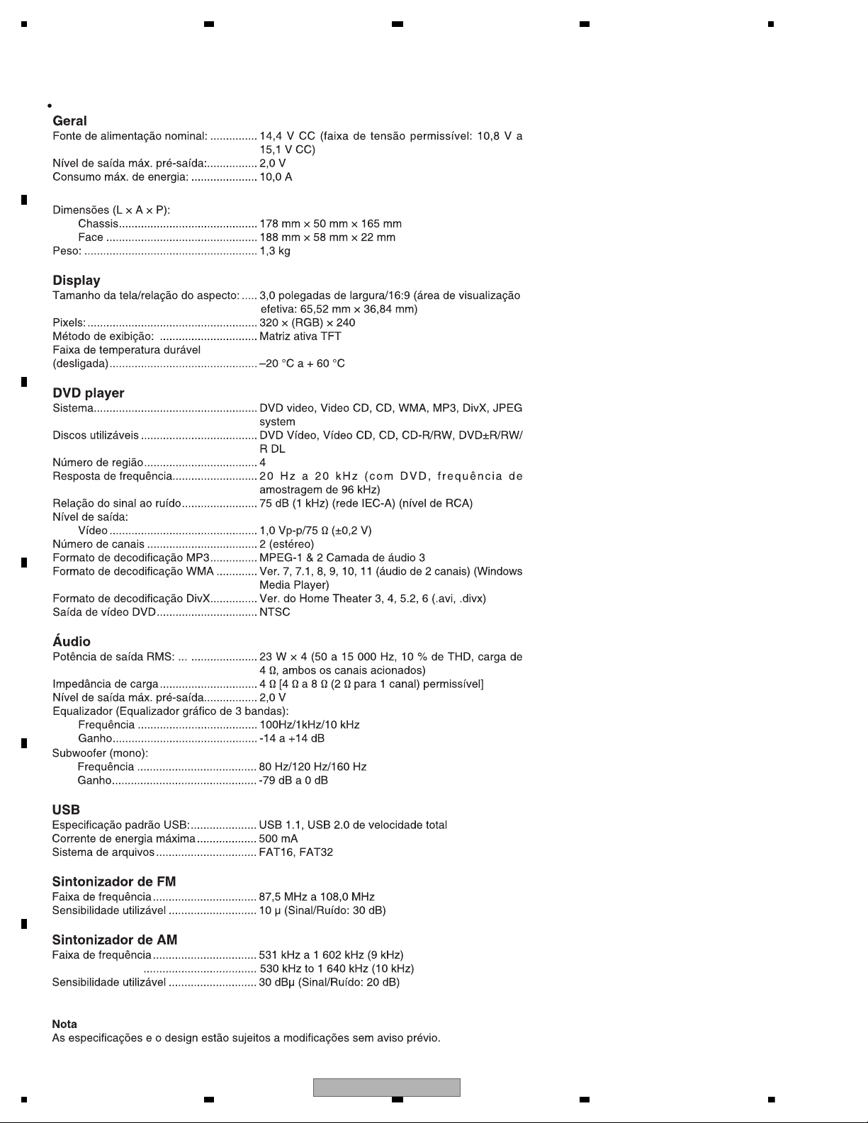
General
Rated power source: ............................... 14.4 V DC (allowable voltage range: 12.0 V to 14.4 V
DC)
Preout maximum output level: ................. 2.0 V
Maximum current consumption: ............. 10.0 A
Dimensions (W × H × D):
Chassis ............................................ 178 mm × 50 mm × 165 mm
Nose ................................................ 188 mm × 58 mm × 22 mm
Weight: .................................................... 1.3 kg
Display
Screen size/aspect ratio: ......................... 3.0 inch wide/16:9 (effective display area: 65.52 mm
× 36.84 mm)
Pixels: ...................................................... 320 × (RGB) × 240
Display method: ..................................... TFT active matrix
Durable temperature range (power off) ... –20 °C to + 60 °C
DVD Player
System..................................................... DVD video, Video CD, CD, WMA, MP3, DivX, JPEG
system
Usable discs ............................................ DVD video, Video CD, CD, CD-R/RW, DVD±R/RW/
R DL
Region number ........................................ 4 for Latin America models
Region number ........................................ 2 for Middle East Asian models
Frequency response ................................ 20 Hz to 20 kHz (with DVD, at sampling frequency
96 kHz)
Signal-to-noise ratio................................. 75 dB (1 kHz) (IEC-A network) (RCA level)
Output level:
Video ............................................... 1.0 Vp-p/75 Ω (±0.2 V)
Number of channels ................................ 2 (stereo)
MP3 decoding format .............................. MPEG-1 & 2 Audio Layer 3
WMA decoding format ............................. Ver. 7, 7.1, 8, 9, 10, 11 (2ch audio) (Windows Media
Player)
DivX decoding format .............................. Home Theater Ver. 3, 4, 5.2, 6 (.avi, .divx)
DVD video output .................................... NTSC
Audio
Maximum power output: .......................... 50 W × 4
Continuous power output ... .................... 22 W × 4 (50 Hz to 15 000 Hz, 5 %THD, 4 Ω load,
both channels driven)
Load impedance: ..................................... 4 Ω (4 Ω to 8 Ω (2 Ω for 1 ch) allowable)
Preout maximum output level .................. 2.0 V
Equalizer (3-Band Graphic Equalizer):
Frequency ....................................... 100Hz/1kHz/10 kHz
Gain ................................................. -14 to +14 dB
Subwoofer (mono):
Frequency ....................................... 80 Hz/120 Hz/160 Hz
Gain ................................................. -79 dB to 0 dB
USB
.................... USB 1.1, USB 2.0 full speed
Maximum current supply
USB standard specification:
......................... 500 mA
File system: ............................................. FAT16, FAT32
FM tuner
Frequency range: .................................... 87.5 MHz to 108.0 MHz
Usable sensitivity ..................................... 10 dBµ (S/N: 30 dB)
AM tuner
Frequency range: .................................... 531 kHz to 1 602 kHz (9 kHz)
.................................... 530 kHz to 1 640 kHz (10 kHz)
Usable sensitivity:
Specifications and the design are subject to modifications without notice.
.................................... 30 dBµ (S/N: 20 dB)
Note
Backup current ....................................... 3 mA or less
DVH-760AV/XEUW5
7
1234
1234
C
D
F
A
B
E
DVH-7680AV/XEBR
Backup current ....................................... 3 mA or less
8
DVH-760AV/XEUW5
5 678
56
7
8
C
D
F
A
B
E
is a trademark of DVD Format/Logo Licensing Corporation.
To keep the product quality after servicing, please confirm following check points.
No. Procedures Item to be confirmed
1 Confirm whether the customer complain has
been solved.
If the customer complain occurs with the
specific media, use it for the operation check.
The customer complain must not be
reappeared.
Display, video, audio and operations must be
normal.
2 DVD Play back a DVD.
(Menu operation; Title/chapter search)
Display, video, audio and operations must be
normal.
3 CD Play back a CD.
(Track search)
Display, audio and operations must be
normal.
4 FM/AM tuner Check FM/AM tuner action.
(Seek, Preset)
Switch band to check both FM and AM.
Display, audio and operations must be
normal.
5 Check whether no disc is inside the product. The media used for the operating check must
be ejected.
6 Appearance check No scratches or dirt on its appearance after
receiving it for service.
For check items concerning image and voice, please refer to the followings:
Check items concerning image Check items concerning voice
Block-noise Distortion
Crosscut noise Noise
Dot noise Low volume
Distorted image (Image skip) High volume
Low brightness Changes in level
Too bright Pause of sound
Color fading
Partial discoloration
2.2 DISC/CONTENT FORMAT
3. BASIC ITEMS FOR SERVICE
3.1 CHECK POINTS AFTER SERVICING
DVH-760AV/XEUW5
9
1234
1234
C
D
F
A
B
E
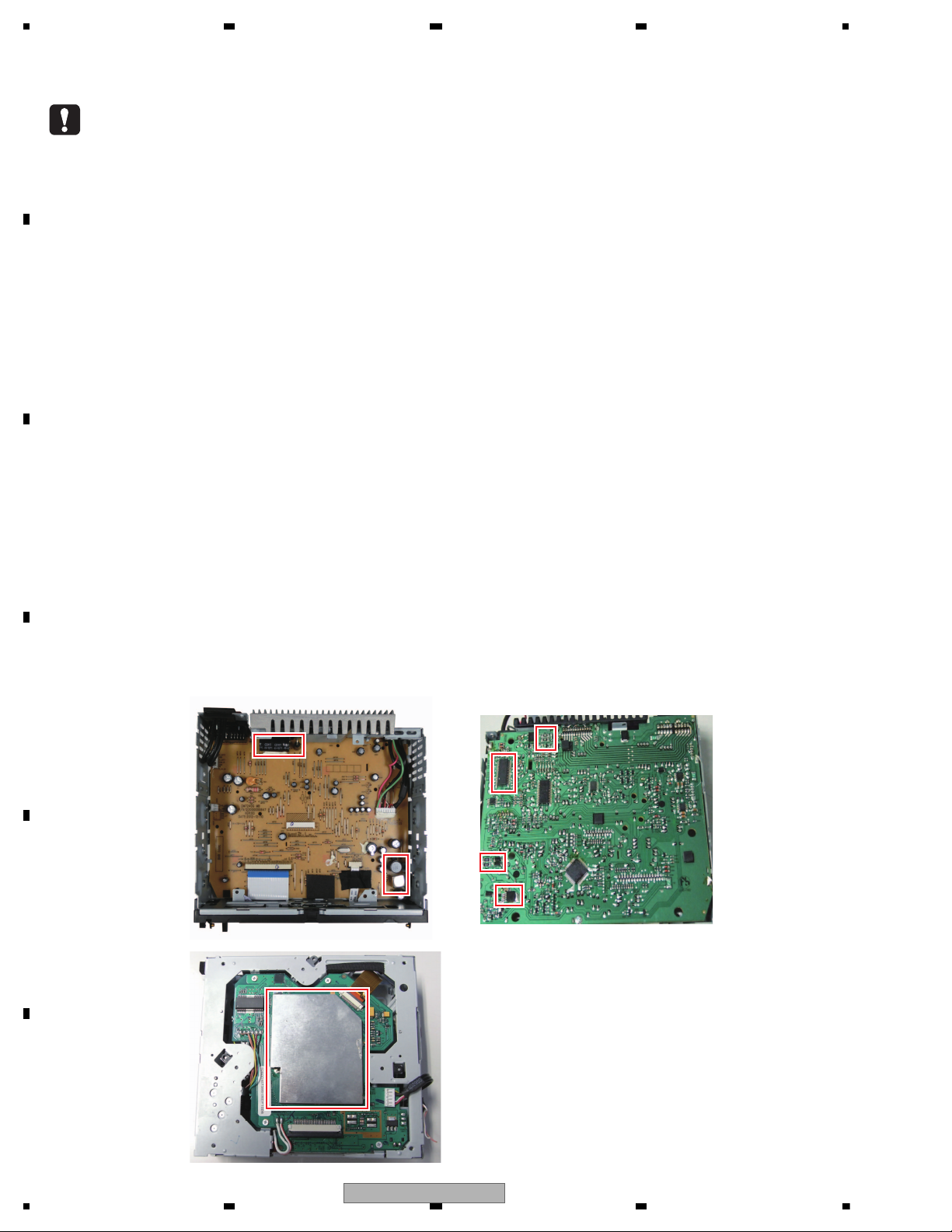
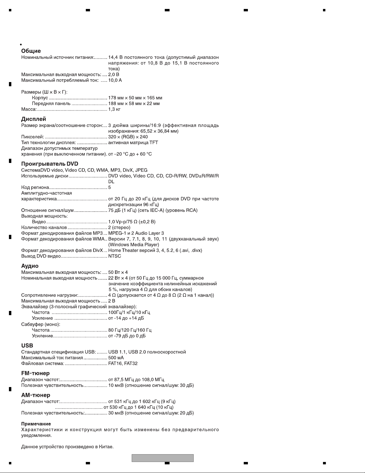
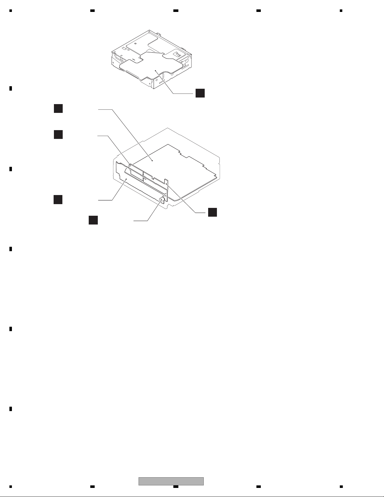
3.2 PCB LOCATIONS
C
KB PCB
C
SB Assy
MB Assy
E
CB Assy
A
LB Assy
F
B
D
AUX PCB
A:DVH-760AV/XEUW5
B:DVH-765AV/XERD
C:DVH-765AV/XERI
D:DVH-7680AV/XFBR
Unit Number : 843DM7240GLMB002(A,B,C)
Unit Number : 883DM7240GBMB002(D)
Unit Name : MB Assy
Unit Number : 842DM7240GRSB002(A)
Unit Number : 842DM7240GLSB002(B)
Unit Number : 842DM7240GMSB002(C)
Unit Number : 882DM7240GBSB002(D)
Unit Name : SB Assy
KB Assy
Consists of
KB PCB
AUX PCB
Unit Number : (A,B,C)
Unit Number : CYW1037(D)
Unit Name : KB Assy
Unit Number : 843DM7240GLCB002(A,B,C)
Unit Number : CYW1038(D)
Unit Name : CB Assy
Unit Number : 843DM7240GLLB002(A,B,C)
Unit Number : CYW1039(D)
Unit Name : LB Assy
10
DVH-760AV/XEUW5
5 678
56
7
8
C
D
F
A
B
E
- Jigs List
Name
21P FFC
Acetate Tape
Jig No.
GGD1627
GYH1026
Remarks
MB Assy (Mother) - SB Assy (DVD Decode)
Disassembly
Before shipping out the product, be sure to clean the following portions by using the prescribed cleaning tools:
Portions to be cleaned Cleaning tools
DVD pickup lenses Cleaning liquid : GEM1004
Cleaning paper : GED-008
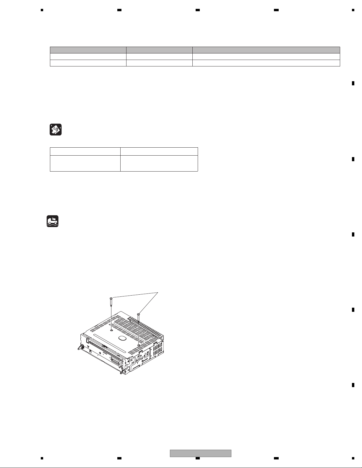
- When the Repair is Complete
When the repair is complete, make the DVD mechanism ready for transportation
implementing the following procedures:
1. Attach the two Transportation Screws.
Now you can transport it.(See the figure below)
Transportation Screws
121045000198-FY
3.3 JIGS LIST
3.4 CLEANING
3.5 FACTORY SETTINGS
DVH-760AV/XEUW5
11
1234
1234
C
D
F
A
B
E
4. BLOCK DIAGRAM
C
KB PCB
C
SB Assy
MB Assy
E
CB Assy
A
LB Assy
F
B
D
AUX PCB
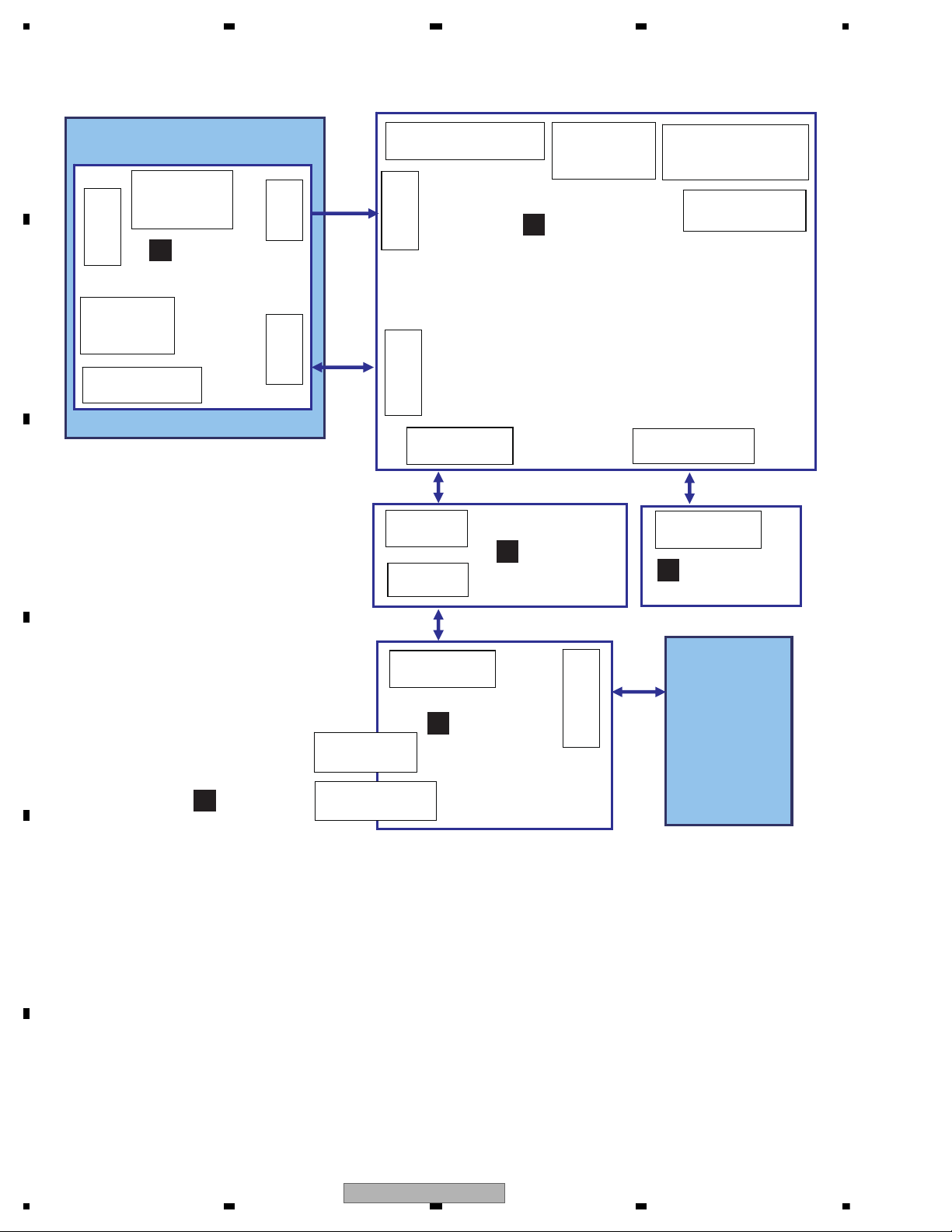
DVD Mechanism module
(Main Board)
(Key Board)
CON202:39pin
TO TFT-LCD
CN204:21pin
TO SB
(Servo Board)
CN6:21pin
TO MB
CN2:6pin
TO Spindle Motor
CN8:24pin
TO Pick-up
CN402:34pin
TO CB
USB201:
USB Connector
CON1
AUX-IN Connector
CN901:20pin
Power Connector
CN201:5pin
Video I/O
Connector
ANT101:
Tuner Antenna
CN501:8pin
PAK/REV/SWC, etc.
Connector
3.0inch
TFT-LCD
Module
CN202:2pin
TO SB
CN406:6pin
TO LBt
CN7:2pin
TO Loarding
Motor
CN5:2pin
TO Disc sense
Switch
CN3:2pin
TO MB
(Light Board)
CN406:6pin
TO MB
(Connector Board)
CON2:34pin
TO MB
CON1:34pin
TO KB
CON201:34pin
TO CB
4.1 OVERALL CONNECTION DIAGRAM
12
DVH-760AV/XEUW5
5 678
56
7
8
C
D
F
A
B
E
C
KB PCB
C
SB Assy
MB Assy
A
B
D
AUX PCB
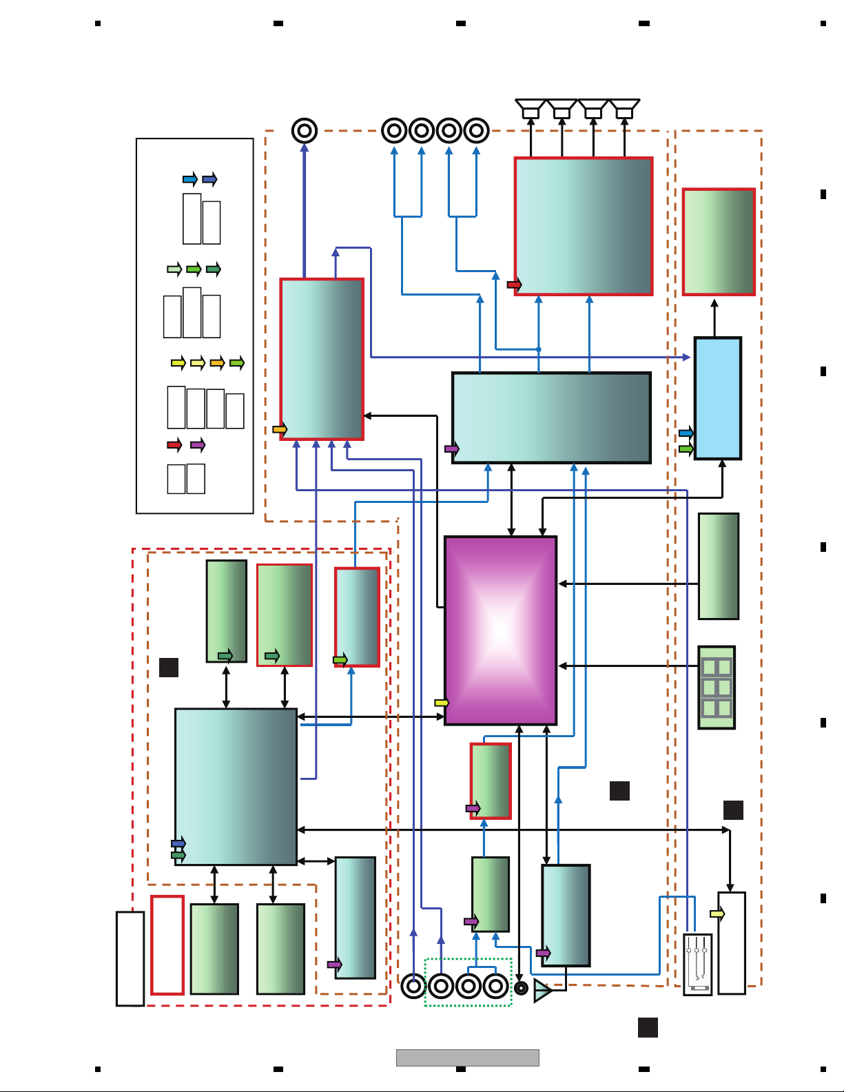
Motor
Servo system
Zoran
ZR36966H
Panel keys
TM030CDH51
3.0“16:9TFT
Display
L/R
FL/FR
Motor Driver
D5869S
Audio
Processor
TDA7419
Jinyuan
A/D
SPI
I
2
C
Power Supply
Video out
Video Switch & Drivers
D6502
I
2
C
Camera in
Front AV-IN
Bu+
UART
I
2
C
SD RAM
M12L64164A
FLASH ROM
MX29LV160DB
TI-70G
CVBS
LINE OUT
Front
Rear/Sub
USB terminal
REMOTE
IR
PICK UP
Audio DAC
ET4344
Power Amplifier
PA2032A
RL/RR
MCU
NEC uPD78F0547
Line/sub
L/R
CVBS
DVD module
D9V
MCU5
VDD3.3 VDD1.8
USB5
BT3.3
+3.3V +1.8V
DVD5
Switch
74HC4052
L/R
Rear AV in
4.7V
ISOAmp
D3 1 2 1
USB
TUNER
TEF6621
Wired
Remote
LCD Driver
TVP5150AM1
DVD Mechanism
DL-303
4.2 BLOCK DIAGRAM
DVH-760AV/XEUW5
13
1234
1234
C
D
F
A
B
E
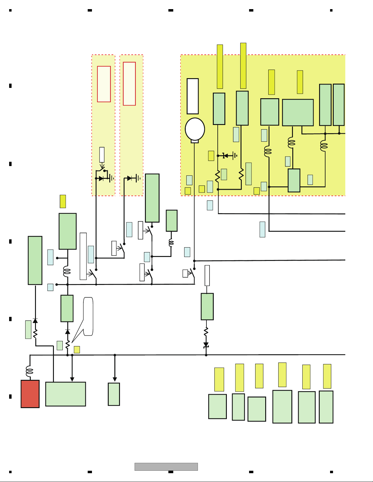
4.3 POWER BLOCK DIAGRAM
U402
U401
U903
U103
U501
U6
U9
U3
U1 U5
U8
U4
P.
AMP
PA2032A
MCU
UPD78F0547AGK
60mA
LM2950-5V
MUTE
Power Amplifier
& Antenna control
MAX:500mA
D5869S
(Motor
driver)
V.02 Dec_15_2011
B+
LM2950-5V
Current
Term 1.5A
AP2191D
MAX:1.5A
5V
9V
MCU5V
ACC or X(LED_OFF_DET)
LED_5V
5V
LB Assy
(LED-Board)
K5V
K5V
D5V
USB:3.3V
for D+/D-
USB_CTL
Power On
BATT
+14.4V
Audio DAC
ET4344
Loarding Motor
D9V A+9V
K5V
4.7V
+5V
MAX:390mA
DC/DC
ACP2809
DVD DSP
Zoran
ZR36966H
+1.8V
SD RAM
M12L64164A-7TG
FLASH
MX29LV160DBTI-70G
M+5V
Ope-Amp
UTC4558
+4.5VA
+3.3V
5V
220R
100R + 10K
MAX:100mA
AP1507-ADJ
MAX:3A
SA1117-3V3
MAX:800mA
SA1117 1V8
MAX:800mA
50R
W-LED
W_LED
CB Assy
(Connector-Board)
RESET
DVD_5V
KTC2020+T
L431=9V
DPAK
MAX:3A
100Ω//100Ω 1/2W
2R2_1W
Max_30mA/Typ_22mA
Max_5.6mA/Typ_3.5mA
EEPROM
FT24C02A
D7035
Low_Check
14
DVH-760AV/XEUW5
5 678
56
7
8
C
D
F
A
B
E
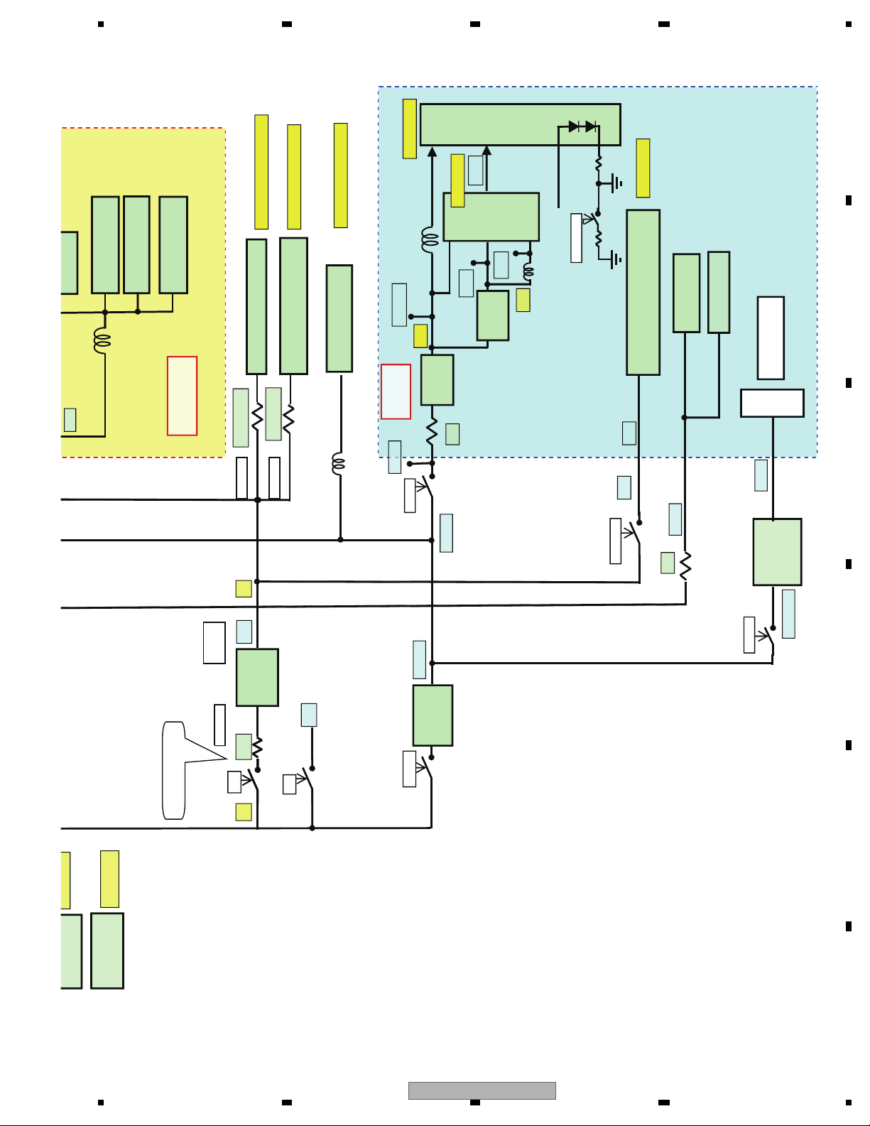
U8
U4
U2
D9V_I
0.518W 0.43A
Q803
0.050W U101
0.005W U904
Q801:DMP3098
U201
U802
U202
U203
U201
REM201
U403
B+
SB unit
(MPEG_BOARD)
KB PCB
(TFT-Board)
SA1117
-3V3
TFT
Driver
TVP5150
MAX:120mA
MAX:200mA
AP1507-ADJ
Key illumination
RED
SA1117
- 1V8
Current Term
5V 1.5A
AP2191D
9V
D9V
DVD_5V
USB5V
TFT_5V
+5V_M
AVDD
DVD_5V
LAMP_SW
RED
LCD
RED
TFT_5V
SD RAM
M12L64164A-7TG
FLASH
MX29LV160DBTI-70G
EEPROM
S24C16
+3.3V
Audio EQ Processor
TDA7419TR
Max_75mA/Typ_55mA
AM/FM TUNER IC TEF6621
Max_150mA/Typ_134mA
Max_47mA/Typ_37mA
2R2_1/10W
2R2_1/4W
IO_DVDD
DVDD
V_LED
10R
IR Receiver
Rotary Encoder
SA1117-3V3
MAX:800mA
SA1117 1V8
MAX:800mA
USB Connector
2.8R
PB+
D5V
PB+
2R2
1.8V
3.3V
DVD_5V
USB-Power
DVD_5V
MAX:30mA
BD435+TL4
31=9V
DPAK
5.6Ω//5.6Ω 1/2W*2
Video selector & Driver
FMS6502
TFT_LIGHT
DVH-760AV/XEUW5
15
1234
1234
C
D
F
A
B
E
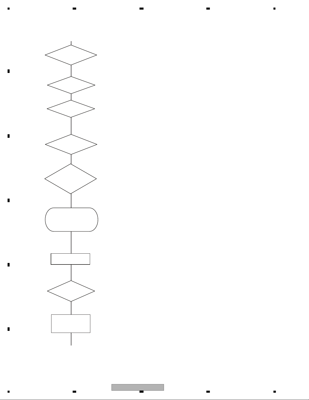
5. DIAGNOSIS
if Acc on
if Press power on key
Acc = 12 V
Starts
communication
with Grille
microcomputer.
Source keys
operative
Source ON
Completes power-on operation.
(After that, proceed to each source operation)
Power ON
Battery = 12 V
DVD Power = 5 V
Vcc = 5 V
TFT Power
On and TFT
Init
Entery select
mode
operative
5.1 OPERATIONAL FLOWCHART
16
DVH-760AV/XEUW5
5 678
56
7
8
C
D
F
A
B
E
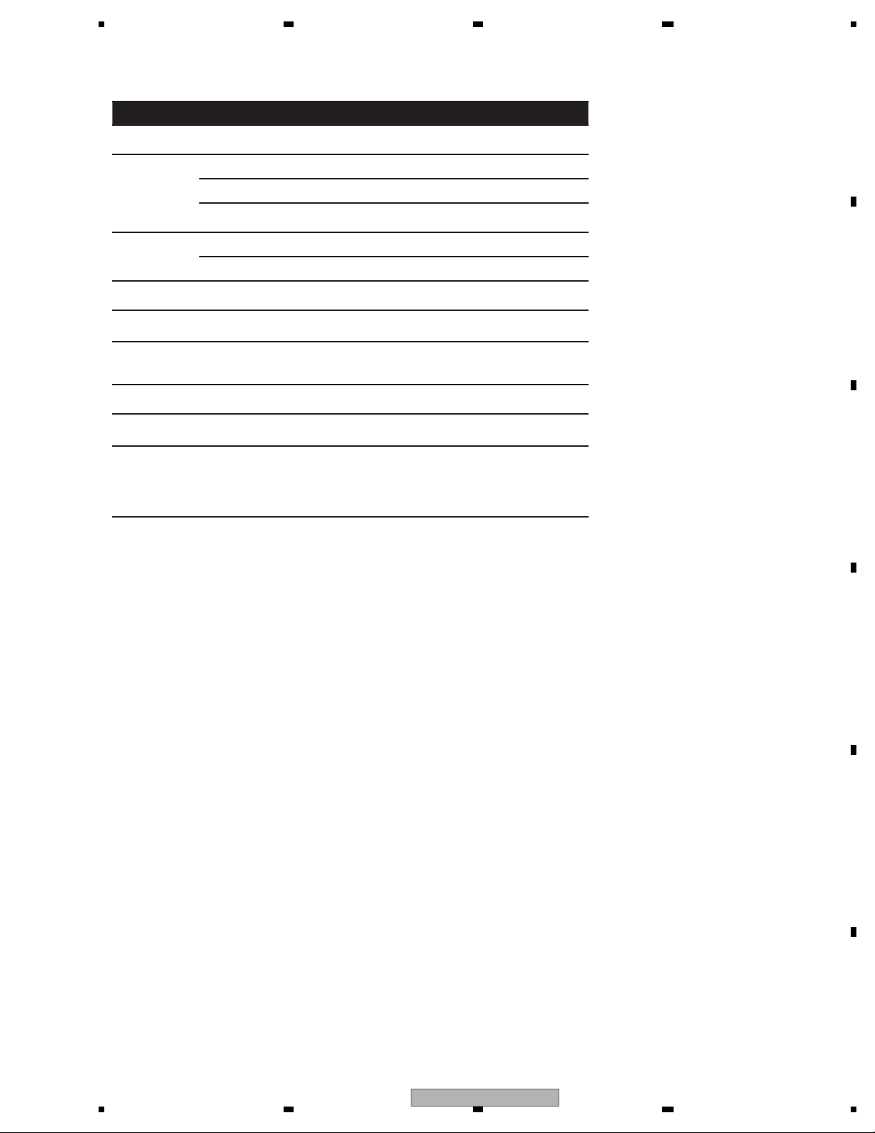
Message Cause Action
Loading Disc is being read.
Please wait, it may take several minutes
for some disc or storage device.
No Disc
Disc is dirty. Clean disc with soft cloth.
Disc is upside down. Insert disc with label side up.
Disc not present in loading
compartment.
Insert disc.
Bad Disc
Disc is dirty. Clean disc with soft cloth.
Disc is upside down. Insert disc with label side up.
Unknown disc
Disc format is not compatible
The file is not supported.
with this unit.
Change another disc.
Change to a supported file.
Change to a supported file.
content
Wrong file
Video
resolution not
supported
The video resolutionexceeds
720X576.
Region Error
DVD is not compatible with
region code of unit.
Use discs with corresponding regional
code.
Error Illegal mechanism operation.
Press EJECT key for 5 seconds to reset
loading mechanism.
AMP ERROR
Unit fails to operate or speaker
connection is incorrect;
protective circuit is activated.
Check the speaker connection. If the
message fails to disappear even after the
engine is switched off/on, contact your
dealer or an authorized Pioneer Service
Station for assistance.
5.2 ERROR CODE LIST
DVH-760AV/XEUW5
17
1234
1234
C
D
F
A
B
E
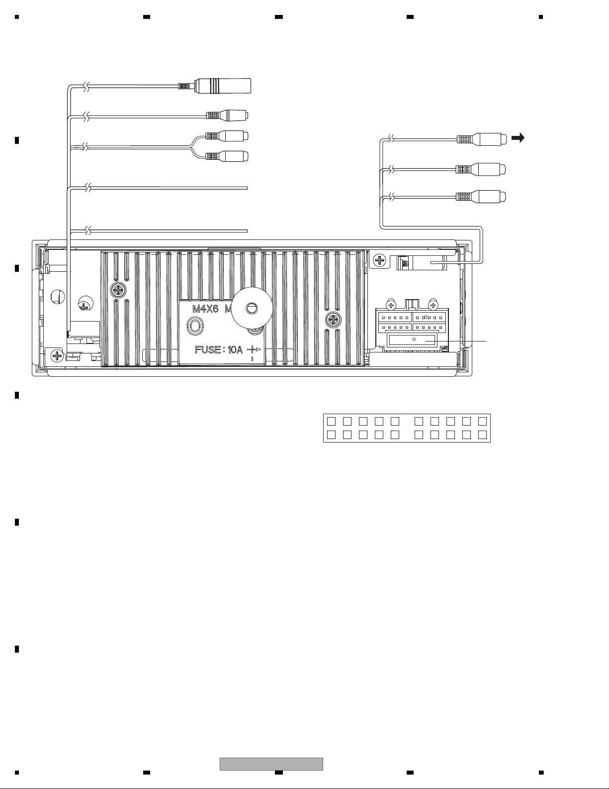
5.3 CONNECTOR FUNCTION DESCRIPTION
1: FR2: FL+
3: FR+
4: FL5: RR+
6: ILLU_IN
7: RR8: ANT
9: T_MUTE
10: +B
9
10
11
12
13
14
15
16
1
2
34567
8
17
18
19
20
11: RL+
12: GND
13: RL14: LO-FL
15: ACCIN
16: LO-FR
17: GND
18: GND
19: LO/SUB-RR
20: LO/SUB-RL
Fuse 10A
(Pink)
REVERSE
SWC (Steering Wheel Control)
AUDIO IN (AV)
RADIO ANTENNA
R(Red)
L(White)
(Light Green/White)
PARKING SW
(Active low level input)
VIDEO OUT
(Yellow)
(Yellow)
CAMERA IN
(Yellow)
VIDEO IN (AV)
To Monitor with
NTSC system
18
DVH-760AV/XEUW5
5 678
56
7
8
C
D
F
A
B
E
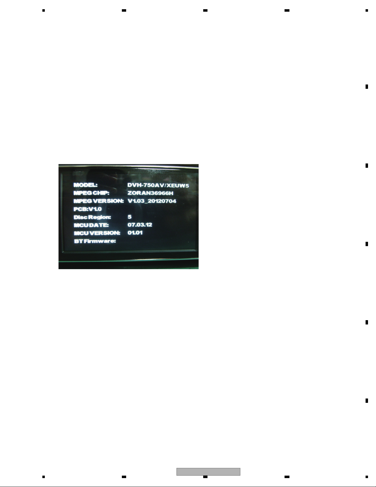
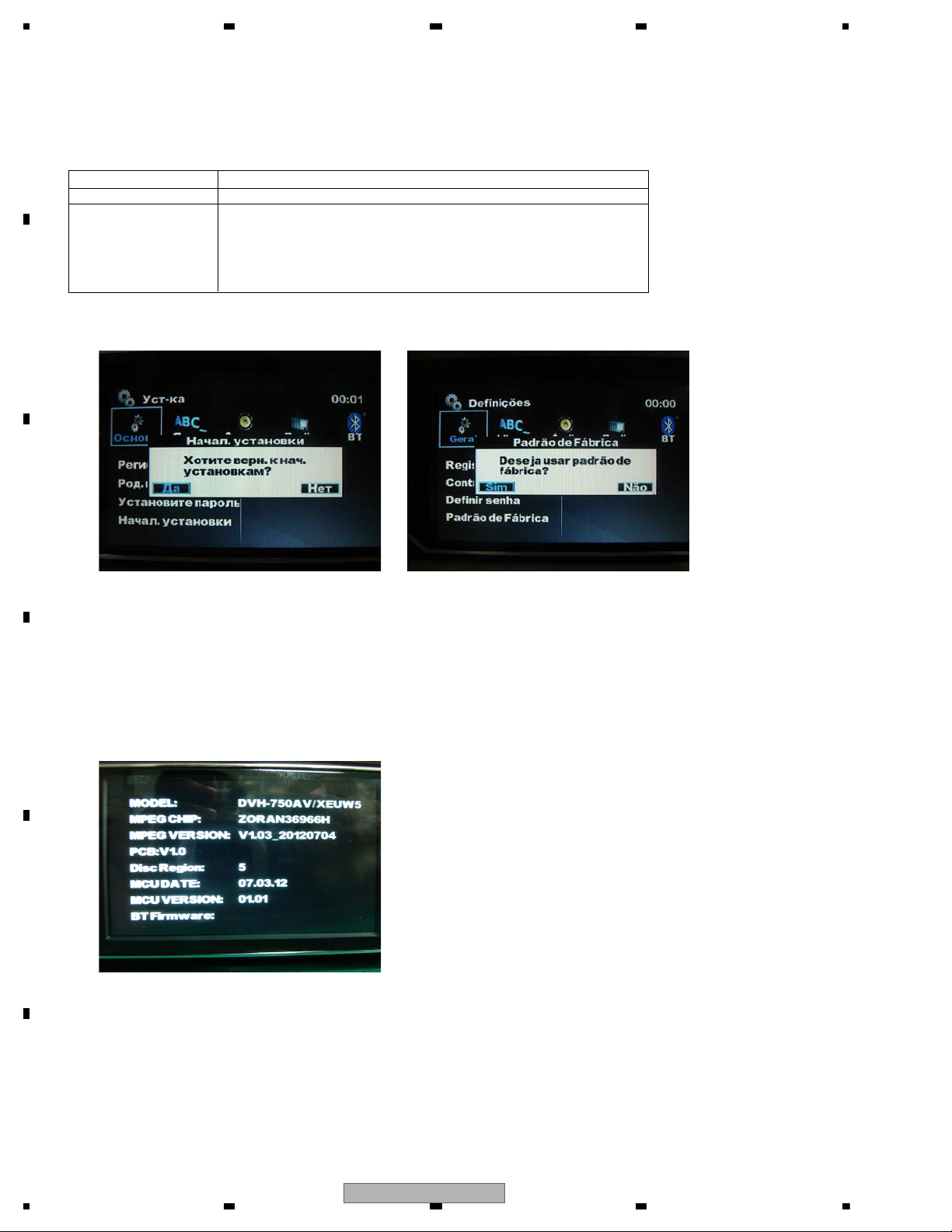
MODEL: DVH-750AV/XEUW5
MPEG CHIP: ZORAN36966H
MPEG VERSION: V1.03_20120704
PCB:V1.0
Disc Region: 5
MCU DATE: 07.03.12
MCU VERSION: 01.01
BT Firmware:
Example of a display
1) Enter into the setting menu by press and hold [M.C.] (Multi Control).
2) Press "5432" by numeric keys on the remote control.
Then, you will find the version information as shown below.
To exit the version display mode, press the "ESC" key.
6. SERVICE MODE
6.1 SOFTWARE VERSION INFORMATION DISPLAY
DVH-760AV/XEUW5
19
1234
1234
C
D
F
A
B
E
6.2 SOFTWARE VERSION UP METHOD
Save six (6) sorts of file for Version Up (build.img, UPD_MPEG.VER, update.img, UPD_MCU.VER, UPD_BT.VER and
NFOREBT.dfu) on an USB.
Turn the product power to be ON and insert the above mentioned USB.
1. MPEG software update
2. MCU software update
3. BT software update (Only a model with BT functional)
4. Reset, "do default setting" in the setting menu.
5. Check Version
Insertion of USB will display the following Update screen.
UW model
Method of individual upgrading
Prepare files shown below according to the purpose for upgrading the software. (It is not necessary to prepare all files)
Item to upgrade Use software
MPEG build.img , UPD_MPEG.VER
MCU update.img , UPD_MCU.VER
BT NFOREBT.dfu , UPD_BT.VER
Upgrade the software in the order of MPEG, MCU, and BT.
Please be sure to perform Default Settings in the Setting after performing Version Up.
If you do not perform the Version Up, the initialization of MPEG software will not be executed.
In addition, the Main Body Reset SW located at the rear surface of Detach Panel is only for the Restart RESET
of MCU and it does not mean to perform all of the initializations.
(Language Setting: Russian for UW5 model)
BR model
(Language Setting: Portuguese(B) for BR model)
20
DVH-760AV/XEUW5
5 678
56
7
8
C
D
F
A
B
E
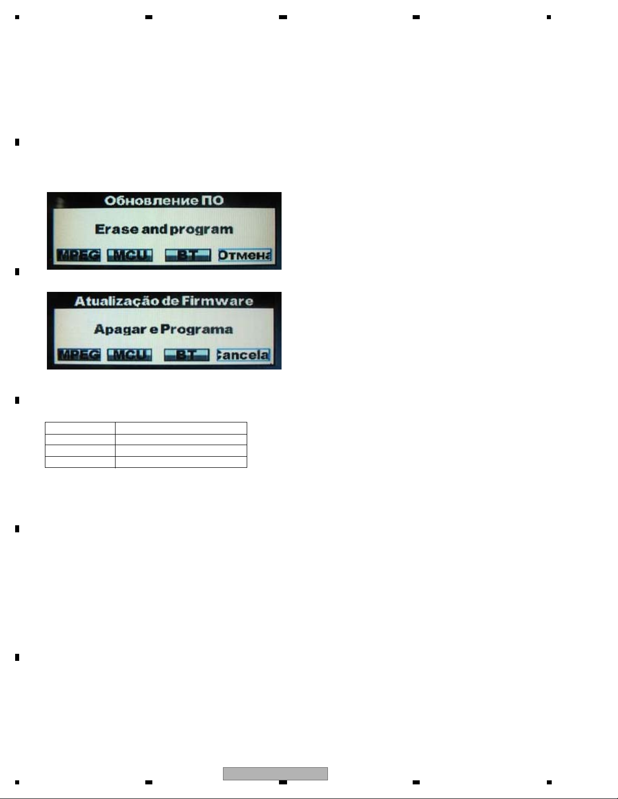
1. MPEG update instruction
1. Copy the MPEG update files(upd_mpeg.ver, build.img) to USB device, and insert it to USB Port,
when the system detect the update file exists, it will pop up a menu like Fig.1 as below:
UW5 model BR model
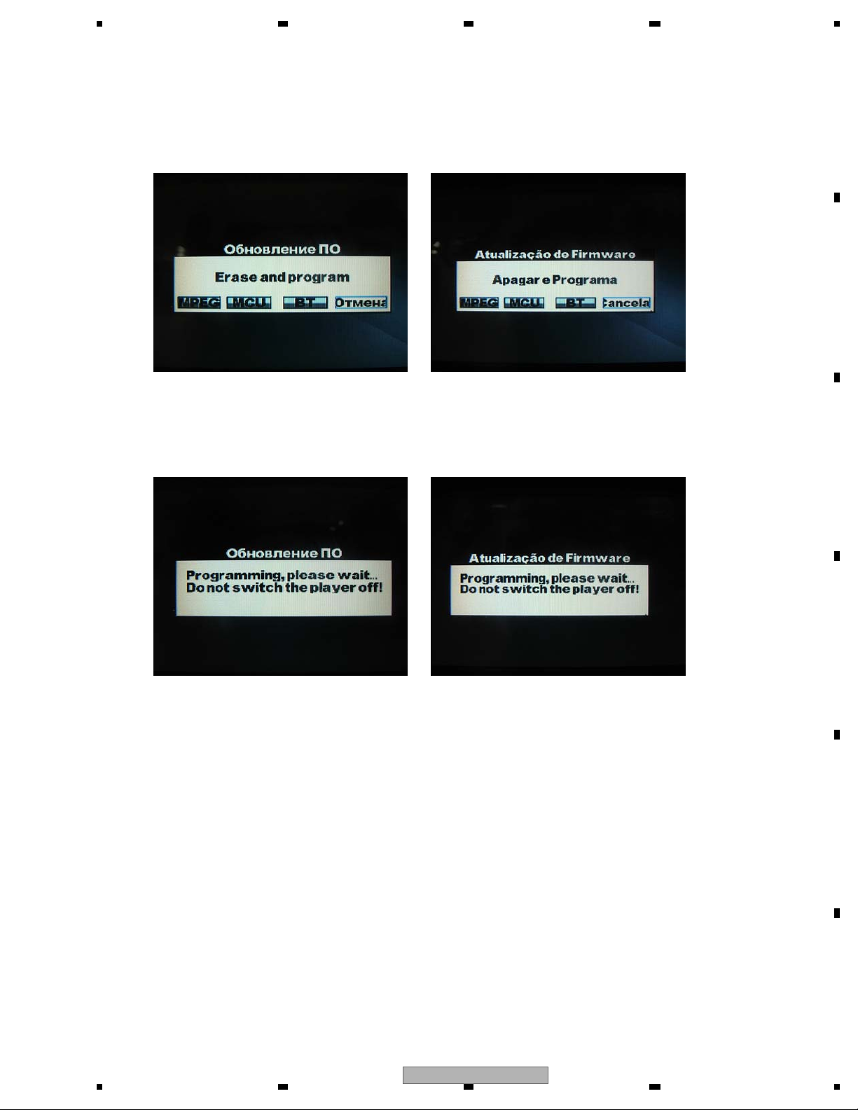
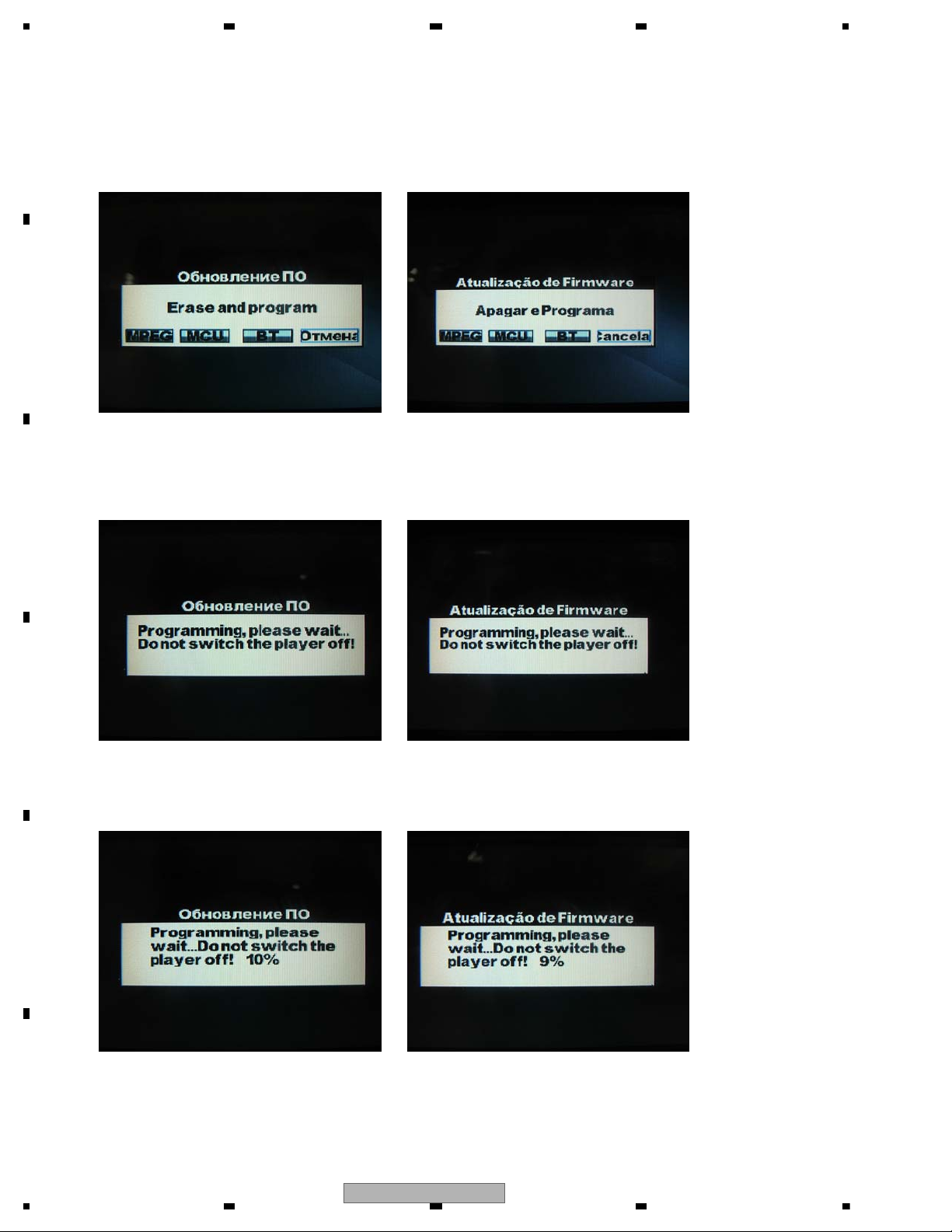
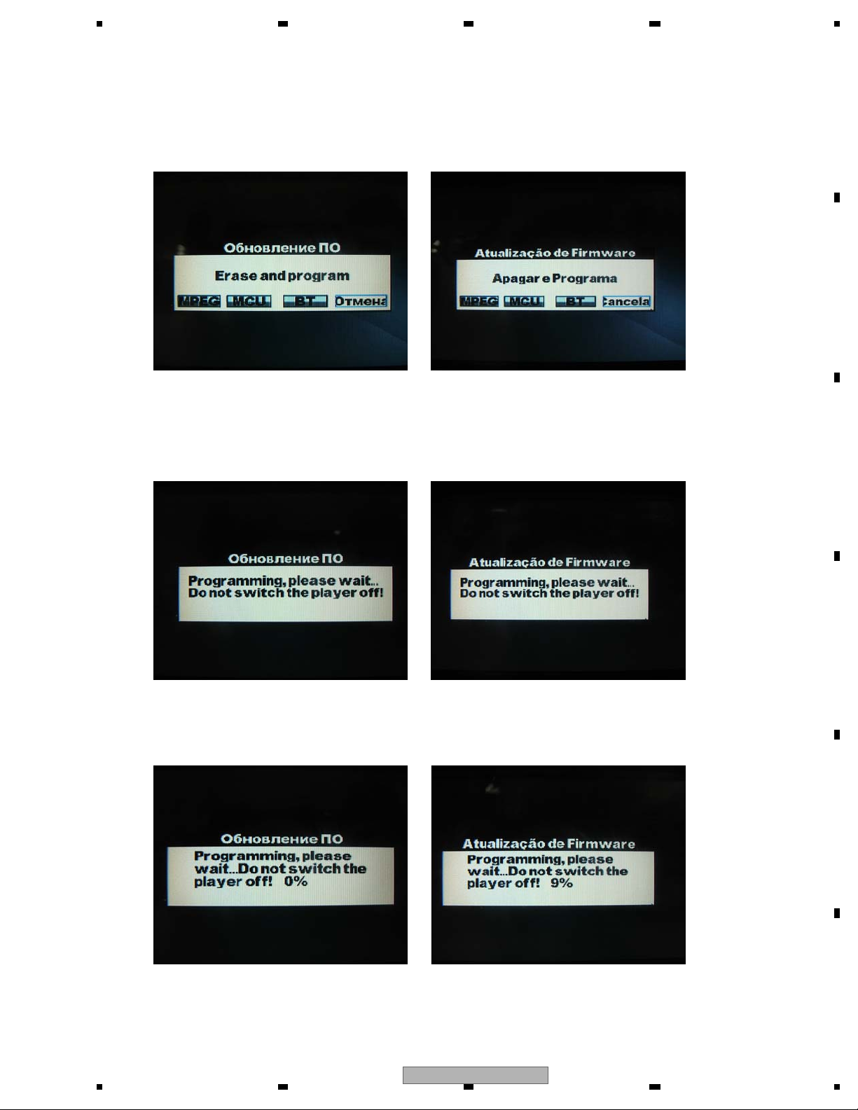
UW5 model BR model
2. If you don’t want to upgrade ,you can press “Cancel” button through Left or Right key of remote control or panel,
otherwise you can move the curse to button “MPEG”, and after pressing Enter key, there will pop other prompt
menu like Fig.2, as below:
3. During the process of upgrade, do not remove the USB device or shut off the power supply, otherwise the system
will breakdown, and never recover any more, if the system restart and pop up Fig.1 for the second time, it means
MPEG upgrade process finished, you can remove the USB device, the whole upgrade process will last about 1 minute;
Fig.1-1 Fig.1-1
Fig.2-1 Fig.2-1
DVH-760AV/XEUW5
21
1234
1234
C
D
F
A
B
E
2. If you don’t want to upgrade, you can press “Cancel” button through Left or Right key of remote control or panel,
otherwise you can move the curse to button “MCU”, and after pressing Enter key, there will pop other prompt menu
like Fig.4, the system start to erase the MCU flash, as below:
UW5 model BR model
UW5 model BR model
3. After erasing process finish, system start to upgrade process, and you will find the upgrade process,
just like Fig.5 as below:
4. During the process of upgrade, it’s allowed the user to remove the USB device, because system had copied the
update files to SDRAM, this is different from MPEG upgrade, after the process reach 100%, which means MCU
upgrade finished, and the system will power off automatically, you need to press the power key to restart the system,
the whole upgrade process will take around 2.5 Minutes
UW5 model BR model
2. MCU update instruction
1. Copy the MCU update files(UPD_MCU.VER, update.img) to USB device, and insert it to USB port,
when the system detect the update file exists, it will pop up a menu like Fig.3, as below:
Fig.3-1 Fig.3-1
Fig.4-1 Fig.4-1
Fig.5-1 Fig.5-1
22
DVH-760AV/XEUW5
5 678
56
7
8
C
D
F
A
B
E
UW5 model BR model
UW5 model BR model
UW5 model BR model
2. If you don’t want to upgrade, you can press “Cancel” button through Left or Right key of remote control or panel,
otherwise you can move the curse to button “BT”, and after pressing Enter key, there will pop other prompt menu
like Fig.7, the system start to erase the BT flash, as below:
3. After erasing process finish, system start to upgrade process, and you will find the upgrade process,
just like Fig.8 as below:
4. During the process of upgrade, it’s allowed the user to remove the USB device, because system had copied the
update files to SDRAM, this is different from MPEG upgrade, after the process reach 100%, which means BT
upgrade finished, and the system will power off automatically, you need to press the power key to restart the system,
the whole upgrade process will take around 2.5 Minutes
3. BT update instruction
1. Copy the BT update files(UPD_BT.VER, NFOREBT.dfu) to USB device, and insert it to USB port,
when the system detect the update file exists, it will pop up a menu like Fig.6, as below:
Fig.6-1 Fig.6-1
Fig.7-1 Fig.7-1
Fig.8-1 Fig.8-1
DVH-760AV/XEUW5
23
1234
1234
C
D
F
A
B
E
UW5 model
-Seetting Menu
BR model
4. Upgrade of software is completed
If upgrade of software is completed, please perform Default setting by Seetting Menu.
How to check the software version, the detailed operation method will be showed as below:
1) Enter into Seetting Menu;
2) Press "5" "4" "3" "2" numeric key on the remote controll
You will find the version information; to exit the version menu, please press "ESC" key
Example of a display
NOTE
:
Item to upgrade Method
Only MPEG USB device is extracted in the state of an Version UP display.
MPEG => MCU 1. USB device is extracted after automatic power switch OFF.
MPEG => MCU => BT 2. Power switch is turned ON.
MCU => BT 3. Default setting is performed by Seetting Menu.
Only MCU
Only BT
24
DVH-760AV/XEUW5
5 678
56
7
8
C
D
F
A
B
E
Deck
1
1
2
3
Fig.1
Fig.2
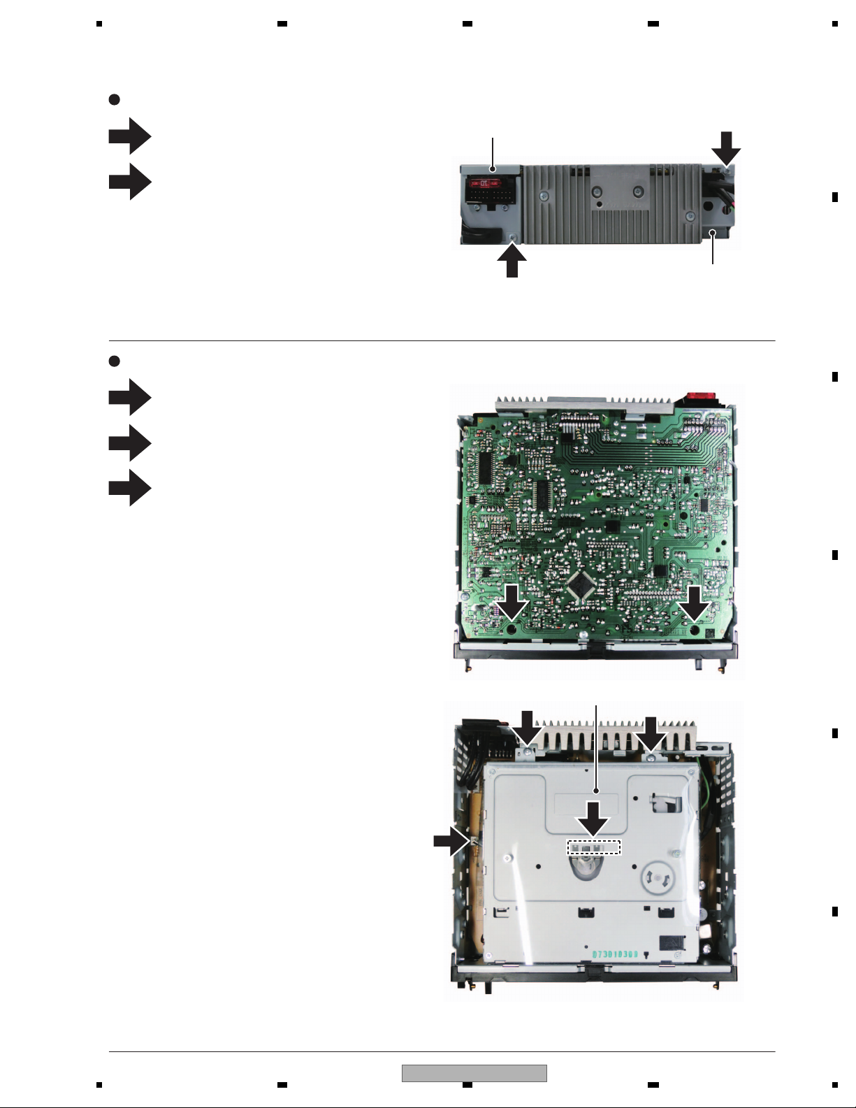
Removing the To p Cover and the Bottom Cover (Fig.1)
Removing the Deck (Fig.2)
Remove the screw and then remove the
Bottom Cover.
Remove the screw and then remove the
To p Cover.
Bottom Cover
To p Cover
2
2
2
1
1
1
2
Remove the two screws.
Remove the two screws.
Disconnect the two connectors and then
remove the Deck.
3
3
7. DISASSEMBLY
DVH-760AV/XEUW5
25
1234
1234
C
D
F
A
B
E
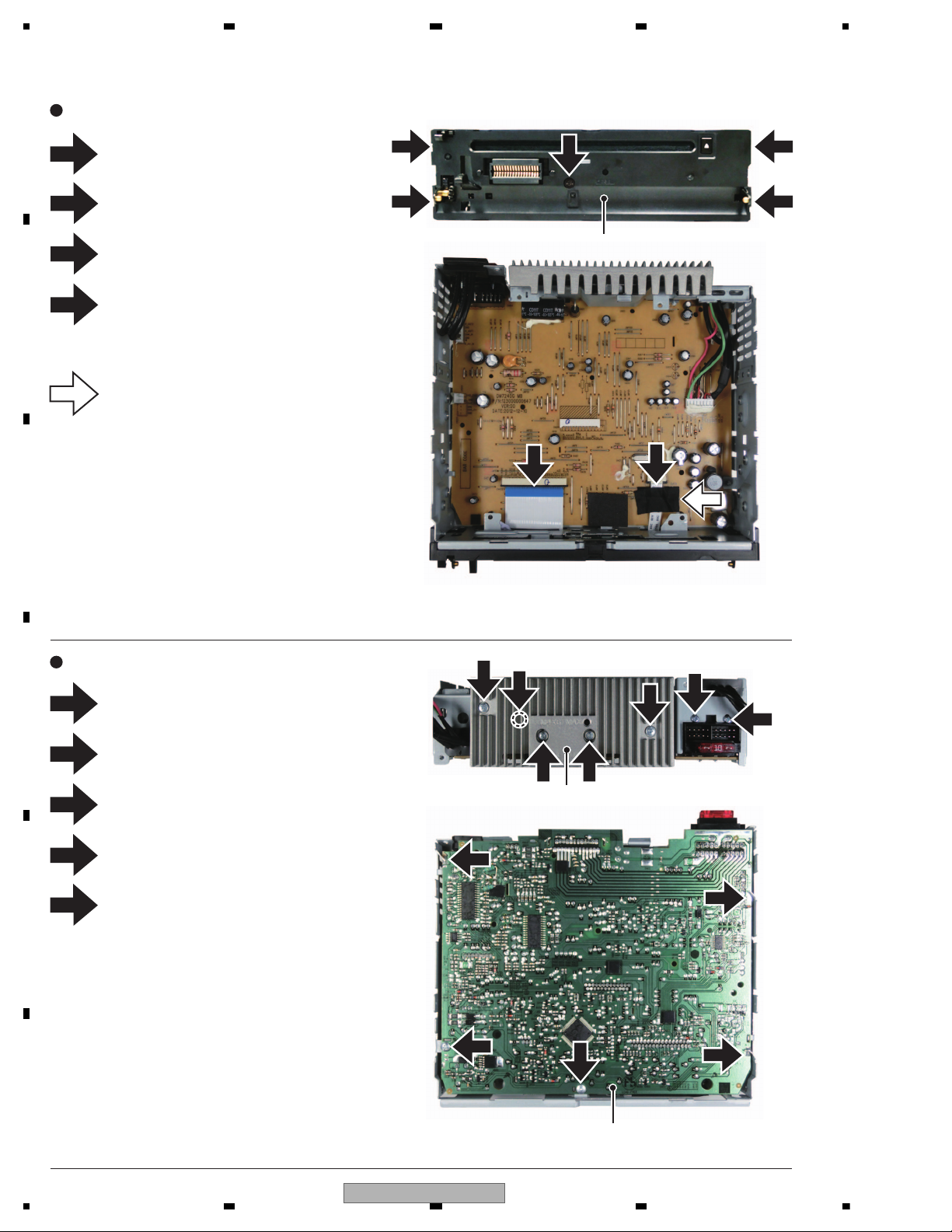
Cabinet
Heatsink
1
1
2
3
4
5
Fig.3
Fig.4
Removing the Cabinet (Fig.3)
Removing the MB Assy (Fig.4)
MB Assy
Disconnect the two connectors.
Remove the screw.
Remove the screw.
Release the three latches and then remove
the Cabinet.
2
3
4
4
4
3
4
5
1
4
4 4
5
2
2
1
2
1
1
22
Remove the two screws.
Remove the four screws and then remove
the Heatsink.
Remove the screw.
Remove the solder at three locations
indicated and then straighten the tabs.
Remove the two screws and then remove
the MB Assy.
3
1
Attension at assembly:
Fix the FFC to MB Assy using the acetate
tape, GYH1026.
1
26
DVH-760AV/XEUW5
 Loading...