

Pioneer DVH-7580AV Schematic
PIONEER CORPORATION 1-1, Shin-ogura, Saiwai-ku, Kawasaki-shi, Kanagawa 212-0031, Japan
PIONEER ELECTRONICS (USA) INC. P.O. Box 1760, Long Beach, CA 90801-1760, U.S.A.
PIONEER EUROPE NV Haven 1087, Keetberglaan 1, 9120 Melsele, Belgium
PIONEER ELECTRONICS ASIACENTRE PTE. LTD. 253 Alexandra Road, #04-01, Singapore 159936
PIONEER CORPORATION 2012
DVD AV RECEIVER
PROVISIONAL
CRT5222P
DVH-750AV/XEUW5
DVH-750AV
DVH-755AV/XERD
DVH-755AV/XERI
DVH-7580AV/XFBR
/
XEUW5
K-ZZZ DEC. 2012 Printed in Japan
1234
1234
C
D
F
A
B
E
SAFETY INFORMATION
Where in a manufacturer’s service documentation, for example in circuit diagrams or lists
of components, a symbol is used to indicate that a specific component shall be replaced only
by the component specified in that documentation for safety reasons, the following symbol shall
be used:
This service manual is intended for qualified service technicians; it is not meant for the casual do-it-yourselfer.
Qualified technicians have the necessary test equipment and tools, and have been trained to properly and safety repair
complex products such as those covered by this manual.
Improperly performed repairs can adversely affect the safety and reliability of the product and may void the warranty.
If you are not qualified to perform the repair of this product properly and safety, you should not risk trying to do so
and refer the repair to a qualified service technician.
This product is a class 1 laser product, but
this product contains a laser diode higher
than Class 1. To ensure continued safety,
do not remove any covers or attempt to
gain access to the inside of the product.
The following caution label appears on
your unit.
Location: on top of the cover
CAUTION: USE OF CONTROLS OR
ADJUSTMENTS OR PERFORMANCE OF
PROCEDURES OTHER THAN THOSE
SPECIFIED HEREIN MAY RESULT IN
HAZARDOUS RADIATION EXPOSURE.
CAUTION: THE USE OF OPTICAL
INSTRUMENTS WITH THIS PRODUCT
WILL INCREASE EYE HAZARD.
- Safety Precautions for those who Service this Unit.
When checking or adjusting the emitting power of the laser diode exercise caution in order to get safe, reliable
results.
Caution:
1. During repair or tests, minimum distance of 13 cm from the focus lens must be kept.
2. During repair or tests, do not view laser beam for 10 seconds or longer.
CAUTION
Danger of explosion if battery is incorrectly replaced.
Replaced only with the same or equivalent type recommended by the manufacture.
Discord used batteries according to the manufacture's instructions.
2
DVH-750AV/XEUW5

5 678
56
7
8
C
D
F
A
B
E
CONTENTS
SAFETY INFORMATION .....................................................................................................................................2
1. SERVICE PRECAUTIONS................................................................................................................................4
1.1 SERVICE PRECAUTIONS.........................................................................................................................4
1.2 NOTES ON SOLDERING...........................................................................................................................4
2. SPECIFICATIONS.............................................................................................................................................5
2.1 SPECIFICATIONS ......................................................................................................................................5
2.2 DISC/CONTENT FORMAT .........................................................................................................................8
3. BASIC ITEMS FOR SERVICE..........................................................................................................................9
3.1 CHECK POINTS AFTER SERVICING.......................................................................................................9
3.2 PCB LOCATIONS.....................................................................................................................................10
3.3 JIGS LIST ................................................................................................................................................. 11
3.4 CLEANING ...............................................................................................................................................11
3.5 FACTORY SETTINGS..............................................................................................................................11
4. BLOCK DIAGRAM ..........................................................................................................................................12
4.1 OVERALL CONNECTION DIAGRAM ......................................................................................................12
4.2 BLOCK DIAGRAM....................................................................................................................................13
4.3 POWER BLOCK DIAGRAM.....................................................................................................................14
5. DIAGNOSIS ....................................................................................................................................................15
5.1 OPERATIONAL FLOWCHART.................................................................................................................15
5.2 ERROR CODE LIST.................................................................................................................................16
5.3 CONNECTOR FUNCTION DESCRIPTION .............................................................................................17
6. SERVICE MODE.............................................................................................................................................18
7. DISASSEMBLY...............................................................................................................................................19
8. EACH SETTING AND ADJUSTMENT............................................................................................................25
9. EXPLODED VIEWS AND PARTS LIST ..........................................................................................................26
9.1 PACKING..................................................................................................................................................26
9.2 EXTERIOR(1)...........................................................................................................................................28
9.3 EXTERIOR(2)(UW5,RD,RI)......................................................................................................................30
9.4 EXTERIOR(2)(BR)....................................................................................................................................32
10. SCHEMATIC DIAGRAM................................................................................................................................34
10.1 MB ASS'Y (1/2) (GUIDE PAGE) .............................................................................................................34
10.2 MB ASS'Y (2/2) (GUIDE PAGE) .............................................................................................................40
10.3 SB ASS'Y (POWER PART) (GUIDE PAGE) ...........................................................................................46
10.4 SB ASS'Y (MAIN PART) (GUIDE PAGE) ...............................................................................................52
10.5 KB PCB and AUX PCB (GUIDE PAGE) .................................................................................................58
10.6 CB ASS'Y and LB ASS'Y........................................................................................................................64
11. PCB CONNECTION DIAGRAM ....................................................................................................................66
11.1 MB ASS'Y ...............................................................................................................................................66
11.2 SB ASS'Y................................................................................................................................................70
11.3 KB PCB...................................................................................................................................................72
11.4 AUX PCB ................................................................................................................................................74
11.5 CB ASS'Y................................................................................................................................................75
11.6 LB ASS'Y ................................................................................................................................................76
12. ELECTRICAL PARTS LIST...........................................................................................................................77
DVH-750AV/XEUW5
3

1234
1234
C
D
F
A
B
E
1. SERVICE PRECAUTIONS
1. You should conform to the regulations govering the product (safety, radio and noise, and other regulations),
and should keep the safety during servicing by following the safety instructions described in this manual.
2. Be careful about an internal sharp edge.
3. Be careful in handling ICs. Some ICs such as MOS type are so fragile that they can be damaged by
electrostatic induction.
4. Be careful in handing made from metal parts. There might be burr at the edge of it.
5. Two kinds of resetting are available
1) Turn over the Detach Panel and press RESET Button at Central Part.
Without entire initialization.
Microcomputer restarting (emergency resetting at function trouble) .
With the reset of the pioneer.
2) Perform [Default Setting] initialization in Setting
Perform product initialization except a part of items.
Please carry it out when updating software.
6. Any component parts in the CD Mechanism Unit of this model can not be supplied.
If you need to replace any parts in the CD Mechanism Unit, replace whole of CD Mechanism Unit.
For environmental protection, lead-free solder is used on the printed circuit boards mounted in this unit.
Be sure to use lead-free solder and a soldering iron that can meet specifications for use with lead-free solders for repairs
accompanied by reworking of soldering.
Compared with conventional eutectic solders, lead-free solders have higher melting points, by approximately 40 C.
Therefore, for lead-free soldering, the tip temperature of a soldering iron must be set to around 373 C in general, although
the temperature depends on the heat capacity of the PC board on which reworking is required and the weight of the tip of
the soldering iron.
Compared with eutectic solders, lead-free solders have higher bond strengths but slower wetting times and higher melting
temperatures (hard to melt/easy to harden).
The following lead-free solders are available as service parts:
Parts numbers of lead-free solder:
GYP1006 1.0 in dia.
GYP1007 0.6 in dia.
GYP1008 0.3 in dia.
1.1 SERVICE PRECAUTIONS
1.2 NOTES ON SOLDERING
4
DVH-750AV/XEUW5
5 678
56
7
8
C
D
F
A
B
E
DVH-750AV/XEUW5
Backup current ....................................... 5 mA or less
2. SPECIFICATIONS
2.1 SPECIFICATIONS
DVH-750AV/XEUW5
5

1234
1234
C
D
F
A
B
E
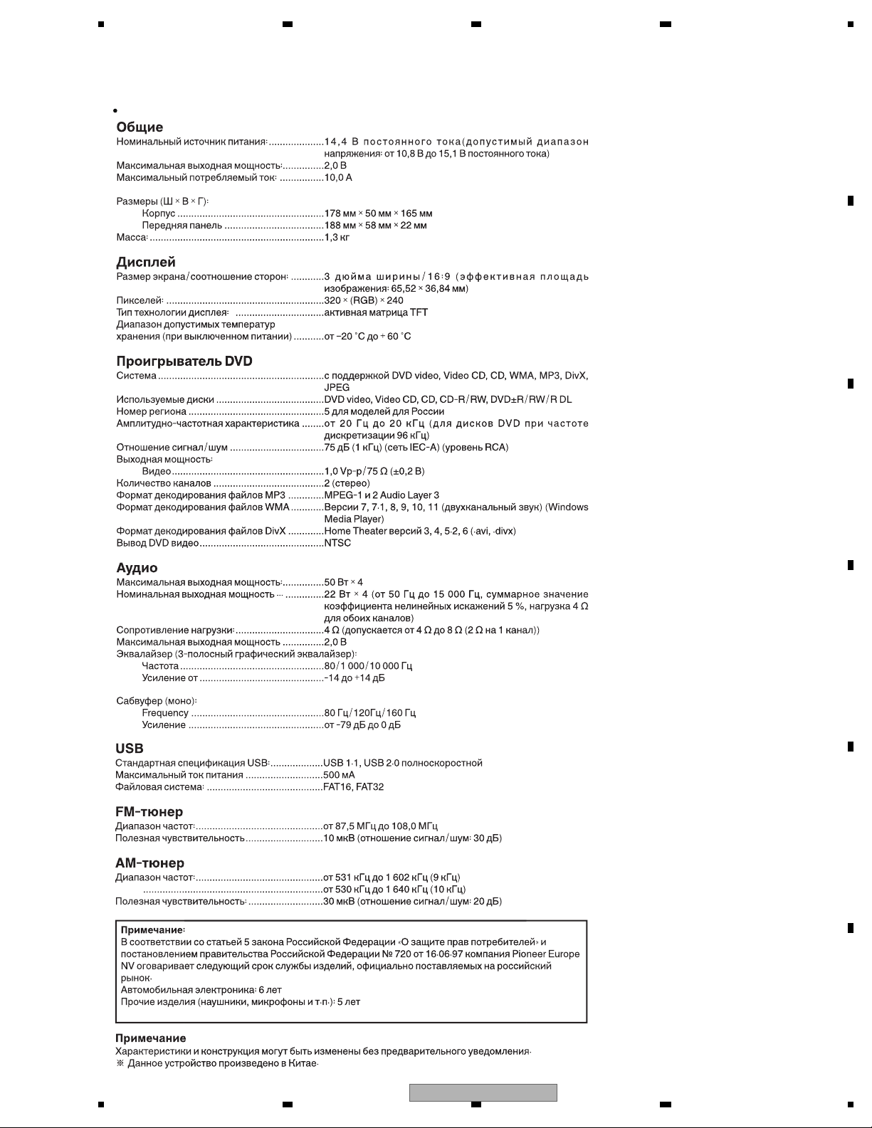
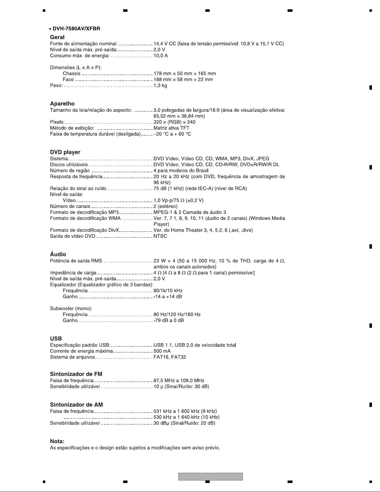
General
Rated power source: ............................... 14.4 V DC (allowable voltage range: 12.0 V to 14.4 V
DC)
Preout maximum output level: ................. 2.0 V
Maximum current consumption: ............. 10.0 A
Dimensions (W × H × D):
Chassis ............................................ 178 mm × 50 mm × 165 mm
Nose ................................................ 188 mm × 58 mm × 22 mm
Weight: .................................................... 1.3 kg
Display
Screen size/aspect ratio: ......................... 3.0 inch wide/16:9 (effective display area: 65.52 mm
× 36.84 mm)
Pixels: ...................................................... 320 × (RGB) × 240
Display method: ..................................... TFT active matrix
Durable temperature range (power off) ... –20 °C to + 60 °C
DVD Player
System..................................................... DVD video, Video CD, CD,WMA, MP3, DivX, JPEG
system
Usable discs ............................................ DVD video, Video CD, CD, CD-R/RW, DVD±R/RW/
R DL
Region number ........................................ 4 for Latin America models
Region number ........................................ 2 for Middle East Asian models
Frequency response ................................ 20 Hz to 20 kHz (with DVD, at sampling frequency
96 kHz)
Signal-to-noise ratio................................. 75 dB (1 kHz) (IEC-A network) (RCA level)
Output level:
Video ............................................... 1.0 Vp-p/75 µ (±0.2 V)
Number of channels ................................ 2 (stereo)
MP3 decoding format .............................. MPEG-1 & 2 Audio Layer 3
WMA decoding format ............................. Ver. 7, 7.1, 8, 9, 10, 11 (2ch audio) (Windows Media
Player)
DivX decoding format .............................. Home Theater Ver. 3, 4, 5.2, 6 (.avi, .divx)
DVD video output .................................... NTSC
Audio
Maximum power output: .......................... 50 W × 4
Continuous power output ... .................... 22 W × 4 (50 Hz to 15 000 Hz, 5 %THD, 4 µ load,
both channels driven)
Load impedance: ..................................... 4 µ (4 µ to 8 µ (2 µ for 1 ch) allowable)
Preout maximum output level .................. 2.0 V
Equalizer (3-Band Graphic Equalizer):
Frequency ....................................... 80/1k/10 kHz
Gain ................................................. -14 to +14 dB
Subwoofer (mono):
Frequency ....................................... 80 Hz/120 Hz/160 Hz
Gain ................................................. -79 dB to 0 dB
USB
.................... USB 1.1, USB 2.0 full speed
Maximum current supply
USB standard specification:
......................... 500 mA
File system: ............................................. FAT16, FAT32
FM tuner
Frequency range: .................................... 87.5 MHz to 108.0 MHz)
Usable sensitivity ..................................... 10 dBµ (S/N: 30 dB)
AM tuner
Frequency range: .................................... 531 kHz to 1 602 kHz (9 kHz)
........................................................ 530 kHz to 1 640 kHz (10 kHz)
Usable sensitivity:
Specifications and the design are subject to modifications without notice.
.................................... 30 dBµ (S/N: 20 dB)
Note:
DVH-755AV/XERD, /XERI
Backup current ....................................... 5 mA or less
6
DVH-750AV/XEUW5
5 678
56
7
8
C
D
F
A
B
E
Backup current ................................................ 5 mA or less
DVH-750AV/XEUW5
7

1234
1234
C
D
F
A
B
E
2.2 DISC/CONTENT FORMAT
is a trademark of DVD Format/Logo Licensing Corporation.
8
DVH-750AV/XEUW5
5 678
56
7
8
C
D
F
A
B
E
To keep the product quality after servicing, please confirm following check points.
No. Procedures Item to be confirmed
1 Confirm whether the customer complain has
been solved.
If the customer complain occurs with the
specific media, use it for the operation check.
The customer complain must not be
reappeared.
Display, video, audio and operations must be
normal.
2 DVD Play back a DVD.
(Menu operation; Title/chapter search)
Display, video, audio and operations must be
normal.
3 CD Play back a CD.
(Track search)
Display, audio and operations must be
normal.
4 FM/AM tuner Check FM/AM tuner action.
(Seek, Preset)
Switch band to check both FM and AM.
Display, audio and operations must be
normal.
5 Check whether no disc is inside the product. The media used for the operating check must
be ejected.
6 Appearance check No scratches or dirt on its appearance after
receiving it for service.
For check items concerning image and voice, please refer to the followings:
Check items concerning image Check items concerning voice
Block-noise Distortion
Crosscut noise Noise
Dot noise Low volume
Distorted image (Image skip) High volume
Low brightness Changes in level
Too bright Pause of sound
Color fading
Partial discoloration
3. BASIC ITEMS FOR SERVICE
3.1 CHECK POINTS AFTER SERVICING
DVH-750AV/XEUW5
9
1234
1234
C
D
F
A
B
E
3.2 PCB LOCATIONS
C
SB ASS'Y
MB ASS'Y
E
CB ASS'Y
KB PCB
A
LB ASS'Y
F
AUX PCB
D
B
A:DVH-750AV/XEUW5
B:DVH-755AV/XERD
C:DVH-755AV/XERI
D:DVH-7580AV/XFBR
Unit Number : 843DM7236GRMB012-FY(A)
Unit Number : 843DM7236GLMB002-FY(B)
Unit Number : 843DM7236GMMB002-FY(C)
Unit Number : CYW1016(D)
Unit Name : MB Ass'y
Unit Number : 843DM7236GRSB001-FY(A)
Unit Number : 843DM7236GLSB001-FY(B)
Unit Number : 843DM7236GMSB001-FY(C)
Unit Number : 883DM7236GBSB001-FY(D)
Unit Name : SB Ass'y
KB ASS'Y
Consists of
KB PCB
AUX PCB
Unit Number : 843DM7236GLKB012-FY(A)
Unit Number : 843DM7236GLKB002-FY(B,C)
Unit Number : CYW1020(D)
Unit Name : KB Ass'y
Unit Number : 843DM7236GLCB002-FY(A,B,C)
Unit Number : CYW1018(D)
Unit Name : CB Ass'y
Unit Number : 843DM7236GLLB002-FY(A,B,C)
Unit Number : CYW1019(D)
Unit Name : LB Ass'y
10
DVH-750AV/XEUW5
5 678
56
7
8
C
D
F
A
B
E
- Jigs List
Name
21P FFC
Jig No.
GGD1627
Remarks
MB Ass'y (Mother) - SB Ass'y (DVD Decode)
Before shipping out the product, be sure to clean the following portions by using the prescribed cleaning tools:
Portions to be cleaned Cleaning tools
DVD pickup lenses Cleaning liquid : GEM1004
Cleaning paper : GED-008
- When the Repair is Complete
When the repair is complete, make the DVD mechanism ready for transportation
implementing the following procedures:
1. Attach the two Transportation Screws.
Now you can transport it.(See the figure below)
Transportation Screws
121045000198-FY
3.3 JIGS LIST
3.4 CLEANING
3.5 FACTORY SETTINGS
DVH-750AV/XEUW5
11
1234
1234
C
D
F
A
B
E
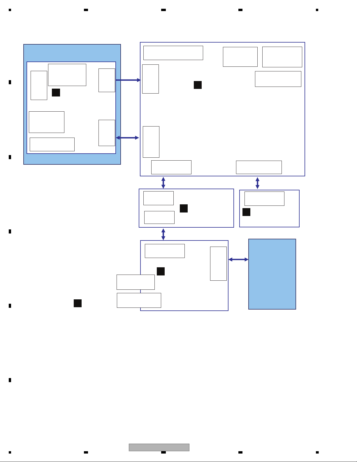
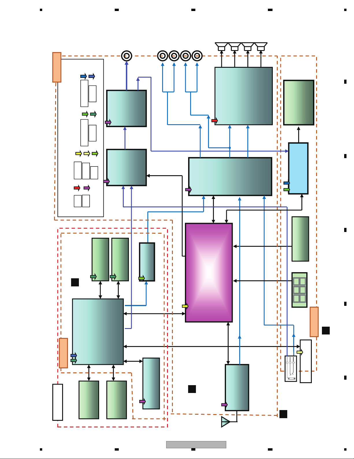
4. BLOCK DIAGRAM
DVD Mechanism Module
MB Ass'y
(Main Board)
KB Ass'y
(Key Board)
CON202:39pin
TO TFT-LCD
CN204:21pin
TO SB
SB Ass'y
(Servo Board)
CN6:21pin
TO MB
CN2:6pin
TO Spindle Motor
CN1:24pin
TO Pick-up
CN402:34pin
TO CB
USB201:
USB Connector
CON1
AUX-IN Connector
CN901:20pin
Power Connector
CN201:2pin
Video output
Connector
ANT101:
Tuner Antenna
CN501:1pin
Parking sense
Connector
3.0inch
TFT-LCD
Module
CN202:2pin
TO SB
CN406:6pin
TO LBt
CN7:2pin
TO Loarding
Motor
CN5:2pin
TO Disc sense
Switch
CN3:2pin
TO MB
LB Ass'y
(Light Board)
CN406:6pin
TO MB
CB Ass'y
(Connector Board)
CON2:34pin
TO MB
CON1:34pin
TO KB
CON201:34pin
TO CB
B
C
A
AUX PCB
D
E
F
4.1 OVERALL CONNECTION DIAGRAM
12
DVH-750AV/XEUW5
5 678
56
7
8
C
D
F
A
B
E
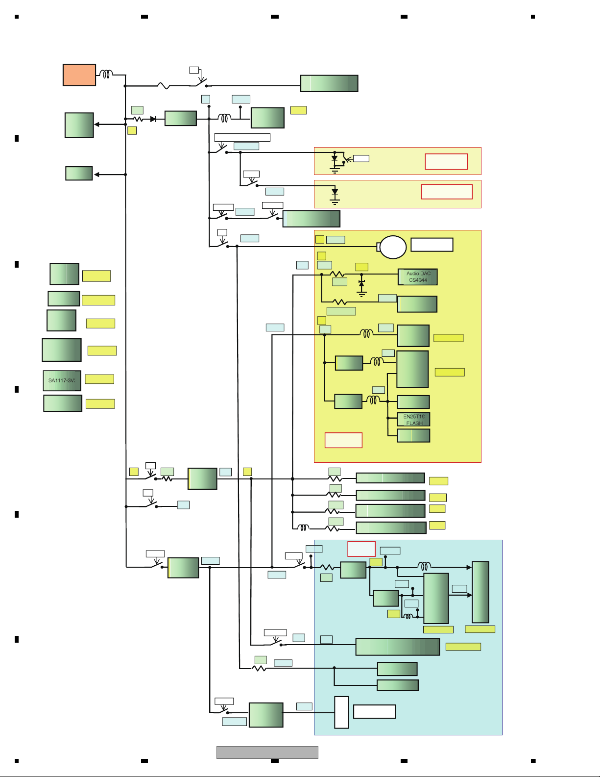
SB Ass'y
B
KB PCB
C
MB Ass'y
A
AUX PCB
D
Motor
Servo system
Zoran
ZR36966H
Panel keys
LCD Driver
TVP5150AM1
A030DW02
3.0“16:9 TFT
Display
Motor Driver
D5869S
TUNER
TEF6621
Audio
Processor
TDA7419TR
USB
A/D
SPI
I
2
C
Power Supply
Video
Preamp
NJM2267
Video out
Video
Switch
BA7613F
I
2
C
Front AV-IN
Front AV-IN
Bu+
L/R
I
2
C
SD RAM
M12L64164A
FLASH ROM
EN25T16
CVBS
LINE OUT
Front
Rear/Sub
USB terminal
USB terminal
REMOTE
IR
PICK UP
Audio DAC
CS4344
Power Amplifier
PA2030A
MCU
NEC uPD78F0547
CVBS
DVD module
KB Ass'y
MB Ass'y
SB Ass'y
D9V
MCU5
DVDD:3.3 AVDD:1.8
USB5
+3.3V +1.8V
4.7V
CVBS
FL/FR
RL/RR
Line/sub
L/R
4.2 BLOCK DIAGRAM
DVH-750AV/XEUW5
13
1234
1234
C
D
F
A
B
E
4.3 POWER BLOCK DIAGRAM
LM2950-5V
D5V
5V
MCU5V
UPD78F0547
ACC or X(LED_OFF_DET)
LED_5V
W_LED
Power On
D5V
K5V
K5V
MCU
AGK
W-LED
USB_CTL
DVD_ 5V
Power Amplifier
& Antenna control
60mA
USB:3.3V
for D+/D-
D9V A+9V
5V
K5V
9V
220R
100R + 10K
5V
+5V
SA1117-
SA1117-
SB Ass'y
(MPEG_BOARD)
RESET
4.7V
1.8
+3.3V
3.3
+4.5VA
M+5V
+1.8V
Audio DAC
CS4344
Ope-Amp
UTC4558
D5869S
(Motor
driver)
DVD DSP
Zoran
ZR36966H
SD RAM
M12L64164A
EN25T16
FLASH
S24C16
EEPROM
(LED-Board)
(Connector-Board)
Loarding Motor
MAX:500mA
MAX:390mA
LB Ass'y
CB Ass'y
BATT
+14.4V
P.
AMP
PA2030A
MUTE
50R
B+
Current
Term 1.5A
AP2191D
LM2950-5V
KTC2020+T
L431=9V
DPAK
MAX:1.5A
MAX:100mA
MAX:3A
AP1507-ADJ
SA1117-3V3
SA1117 1V8
MAX:3A
MAX:800mA
MAX:800mA
PB+
D5V
DVD_5V
2.8R
AP1507-ADJ
PB+
KTC2020+T
L431=9V
DPAK
DVD_5V
DVD_5V
B+
D9V
USB-Power
9V
10R
Current Term
5V 1.5A
AP2191D
DVD_5V
LAMP_SW
+5V_M
TFT_5V
RED
USB5V
TFT_5V
2R2
RED
2R2
AM FM PLL TUNER TEF6621
22R
Audio EQ Processor TDA7419TR
100R
100R
KB Ass'y
(TFT-Board)
SA1117
-3V3
USB Connector
Video
selector
Video
Driver NJM2267M
IO_DVDD
3.3V
SA1117
- 1V8
Key illumination
IR Receiver
Rotary Encoder
BA7613F
DVDD
1.8V
RED
AVDD
150mA
47 mA
**mA
**mA
TFT Driver
TVP5150
MAX:30mA
V_LED
MAX:120mA
MAX:200mA
LCD
14
DVH-750AV/XEUW5
5 678
56
7
8
C
D
F
A
B
E
if Acc on
if Press power on key
Acc = 12 V
Starts
communication
with Grille
microcomputer.
Source keys
operative
Source ON
Completes power-on operation.
(After that, proceed to each source operation)
Power ON
Battery = 12 V
DVD Power = 5 V
Vcc = 5 V
TFT Power
On and TFT
Init
Entery select
mode
operative
5. DIAGNOSIS
5.1 OPERATIONAL FLOWCHART
DVH-750AV/XEUW5
15

1234
1234
C
D
F
A
B
E
5.2 ERROR CODE LIST
Message Cause Action
Loading Disc is being read
Please wait, it may take several minutes
for some disc or storage device.
No Disc
Disc is dirty Clean disc with soft cloth
Disc is upside down Insert disc with label side up
Disc not present in loading
compartment
Insert disc
Bad Disc
Disc is dirty Clean disc with soft cloth
Disc is upside down Insert disc with label side up
Unknown disc
Disc format is not compatible
with this unit
Change another disc.
Region Error
DVD is not compatible with
region code of unit
Use discs with corresponding regional
code.
Error Illegal mechanism operation
Press EJECT key for 5 seconds to reset
loading mechanism
AMP ERROR
Unit fails to operate or speaker
connection is incorrect;
protective circuit is activated.
Check the speaker connection. If the
message fails to disappear even after the
engine is switched off/on, contact your
dealer or an authorized Pioneer Service
Station for assistance.
16
DVH-750AV/XEUW5
5 678
56
7
8
C
D
F
A
B
E
1: FR2: FL+
3: FR+
4: FL5: RR+
6: ILLU_IN
7: RR8: ANT
9: T_MUTE
10: +B
9
10
11
12
13
14
15
16
1234567
8
17
18
19
20
11: RL+
12: GND
13: RL14: LO-FL
15: ACCIN
16: LO-FR
17: GND
18: GND
19: LO/SUB-RR
20: LO/SUB-RL
Fuse 10A
(Light Green/White)
Radio Antenna
Parking SW
(Active low level input)
Video-out
(Yellow)
To Monitor with
NTSC system
5.3 CONNECTOR FUNCTION DESCRIPTION
DVH-750AV/XEUW5
17

1234
1234
C
D
F
A
B
E
6. SERVICE MODE
18
DVH-750AV/XEUW5
5 678
56
7
8
C
D
F
A
B
E
DVD Mechanism Module
1
1
2
3
Fig.1
Fig.2
Removing the Top Cover and the Bottom Cover (Fig.1)
Removing the DVD Mechanism Module (Fig.2)
Remove the screw and then remove the
Bottom Cover.
Remove the screw and then remove the
Top Cover.
Bottom Cover
Top Cover
2
2
2
1 1
1
2
Remove the two screws.
Remove the two screws.
Disconnect the two connectors and then
remove the DVD Mechanism Module.
3
3
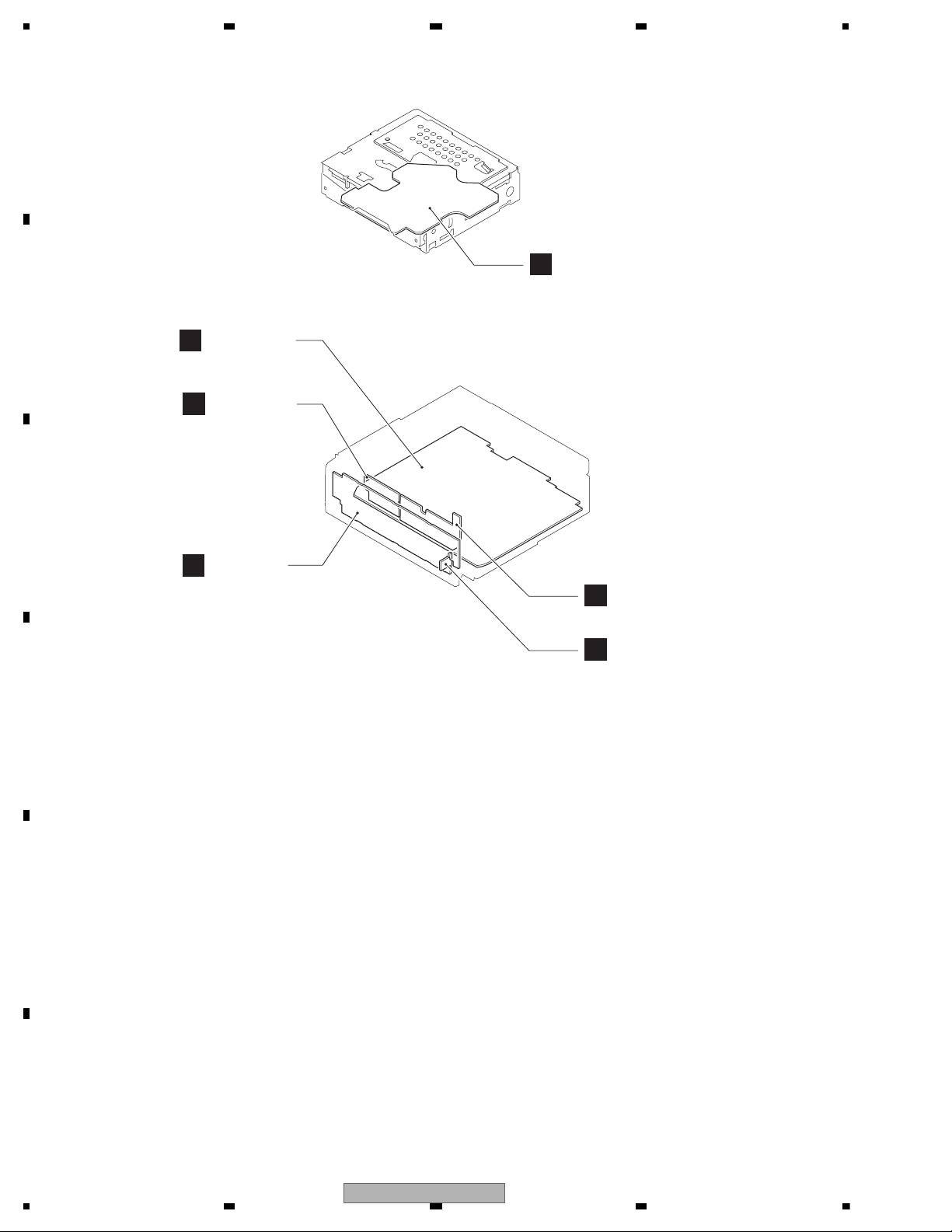
7. DISASSEMBLY
DVH-750AV/XEUW5
19
1234
1234
C
D
F
A
B
E
Cabinet
Heat Sink
1
1
2
3
4
5
Fig.3
Fig.4
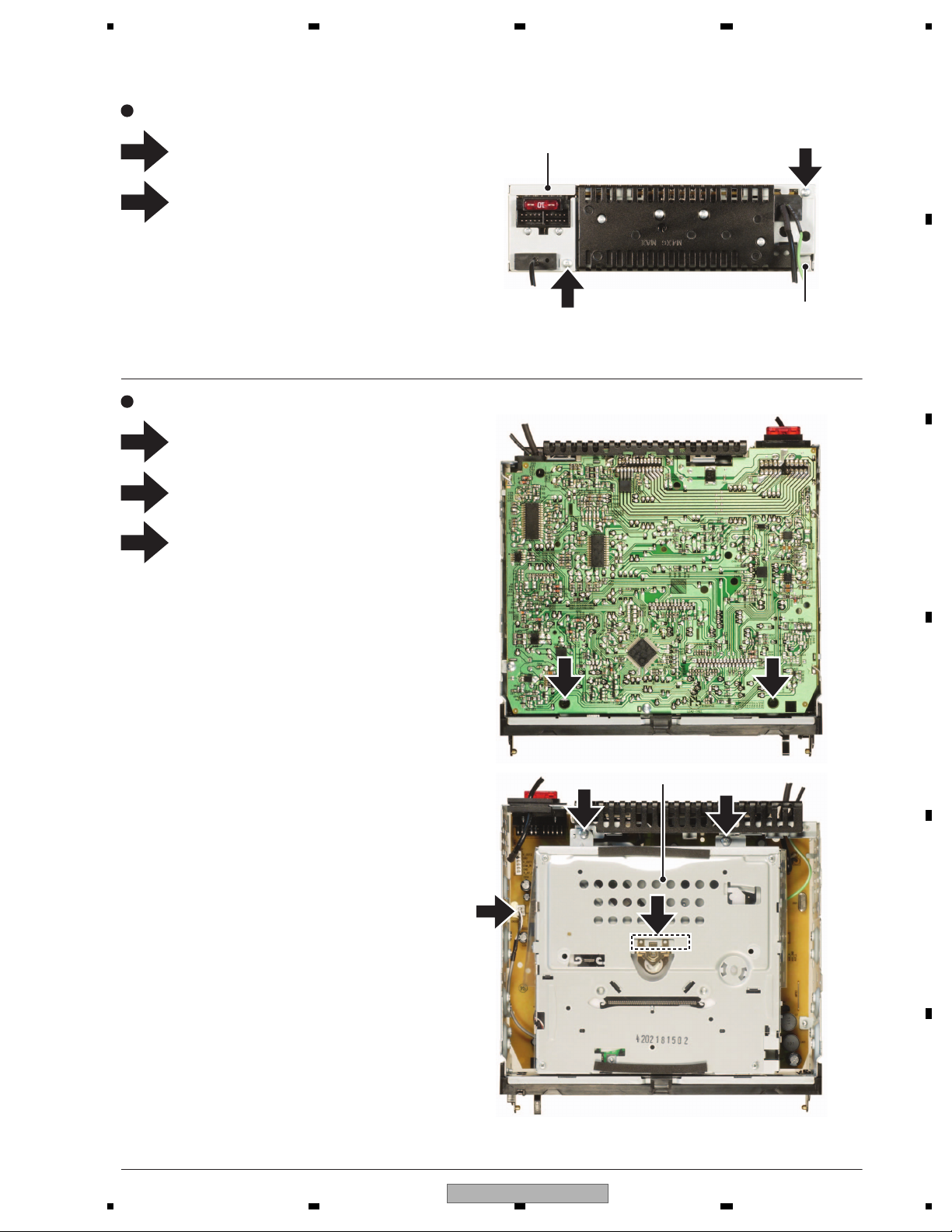
Removing the Cabinet (Fig.3)
Removing the MB Ass’y (Fig.4)
MB Ass’y
Disconnect the two connectors.
Remove the screw.
Remove the screw.
Release the three latches and then remove
the Cabinet.
2
3
4
4
4
3
4
5
1
4
4 4
5
2
2
1
2
1
1
22
Remove the two screws.
Remove the four screws and then remove
the Heat Sink.
Remove the screw.
Remove the solder at three locations
indicated and then straighten the tabs.
Remove the two screws and then remove
the MB Ass’y.
3
20
DVH-750AV/XEUW5
5 678
56
7
8
C
D
F
A
B
E
3
1
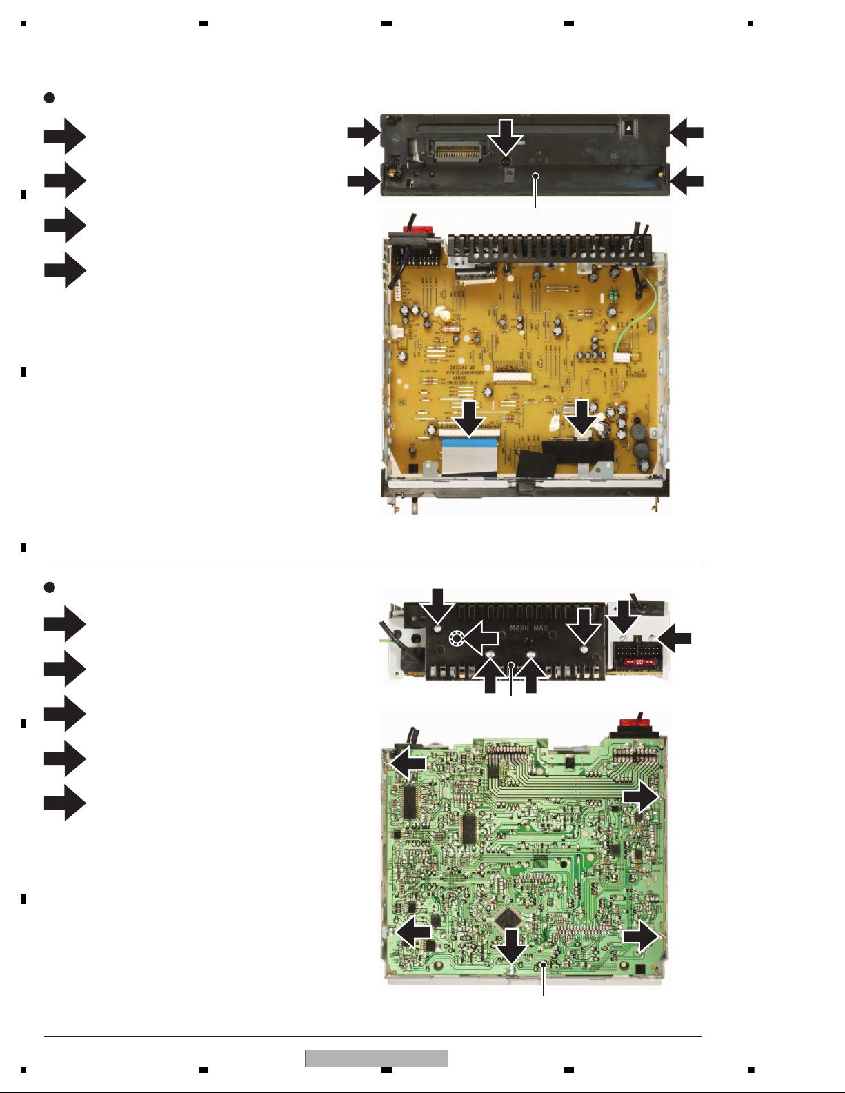
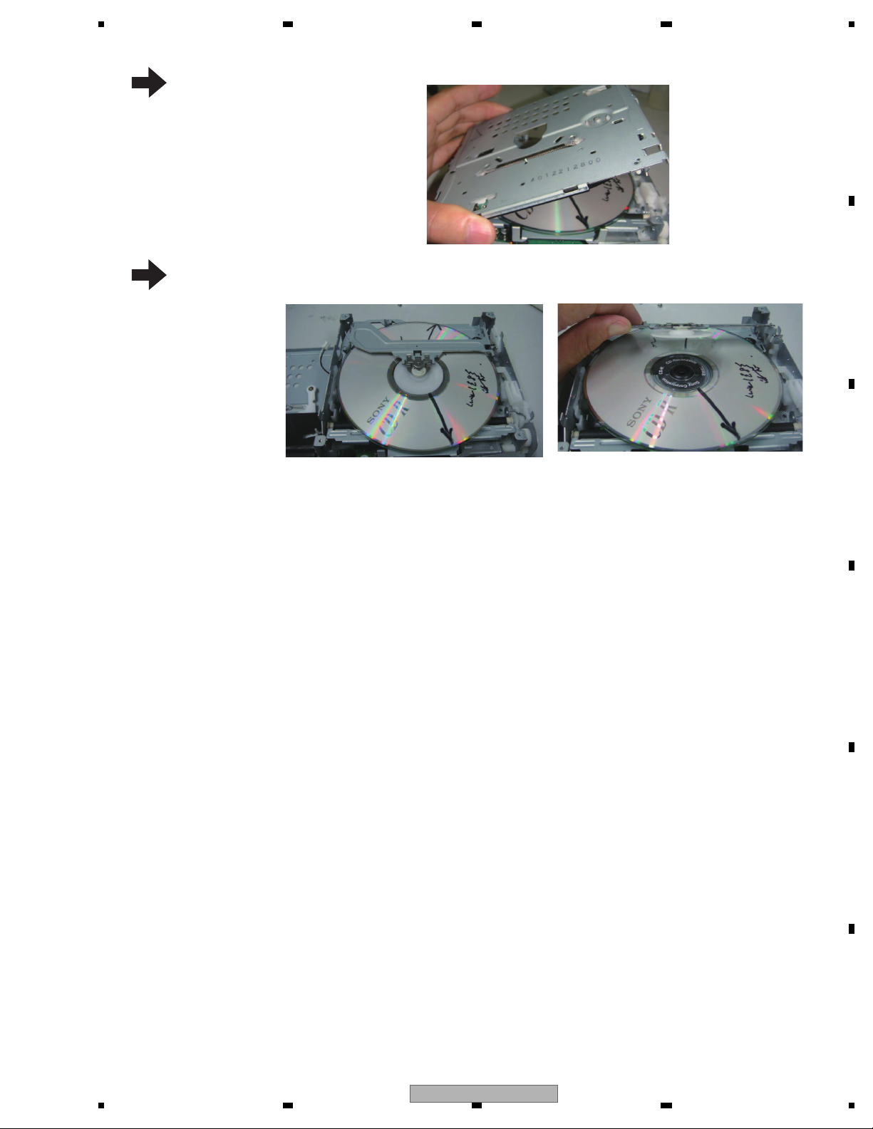
- How to eject the stuck disc (Procedure 1: Rotating the roller)
Remove the DVD
mechanism module.
2
Remove the screws.
Remove the top and the bottom cover.
Rotate the gear upward.
Then, the disc will be ejected.
4
5
Remove the screws.
DVH-750AV/XEUW5
21
1234
1234
C
D
F
A
B
E
3
1
-
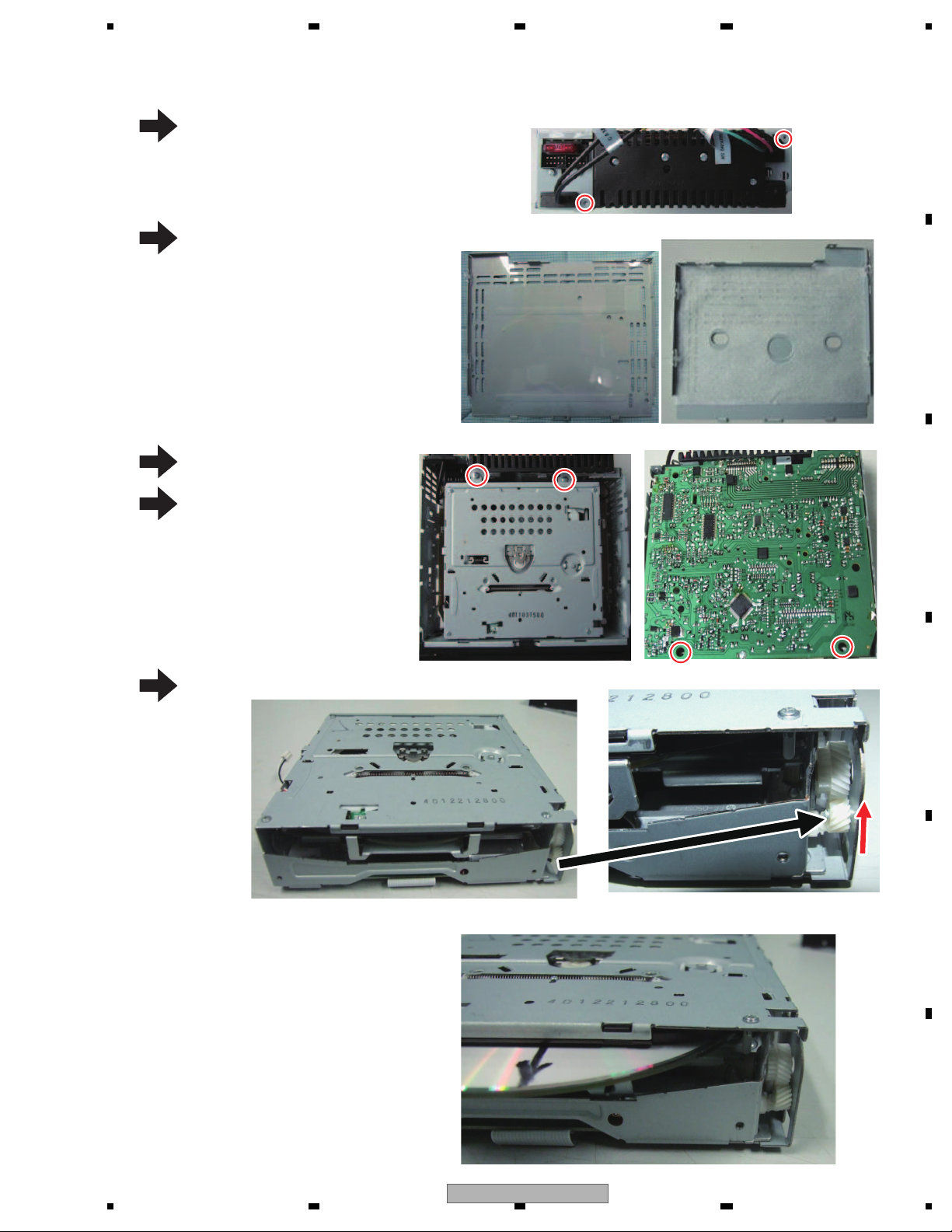
How to eject the stuck disc (Procedure 2: Removing the top cover)
Remove the DVD
mechanism module.
2
Remove the screws.
Remove the top and the bottom cover
of the product.
Remove the screws.
4
5
Remove the screws.
Left side Right sideTo p
7
Remove the dustproof
cover.
6
Remove the screws.
22
DVH-750AV/XEUW5
5 678
56
7
8
C
D
F
A
B
E
8
9
Remove the top cover of
the DVD mechanism.
Lift up the clamp holder,
and remove the disc.
DVH-750AV/XEUW5
23
1234
1234
C
D
F
A
B
E
3
1
-
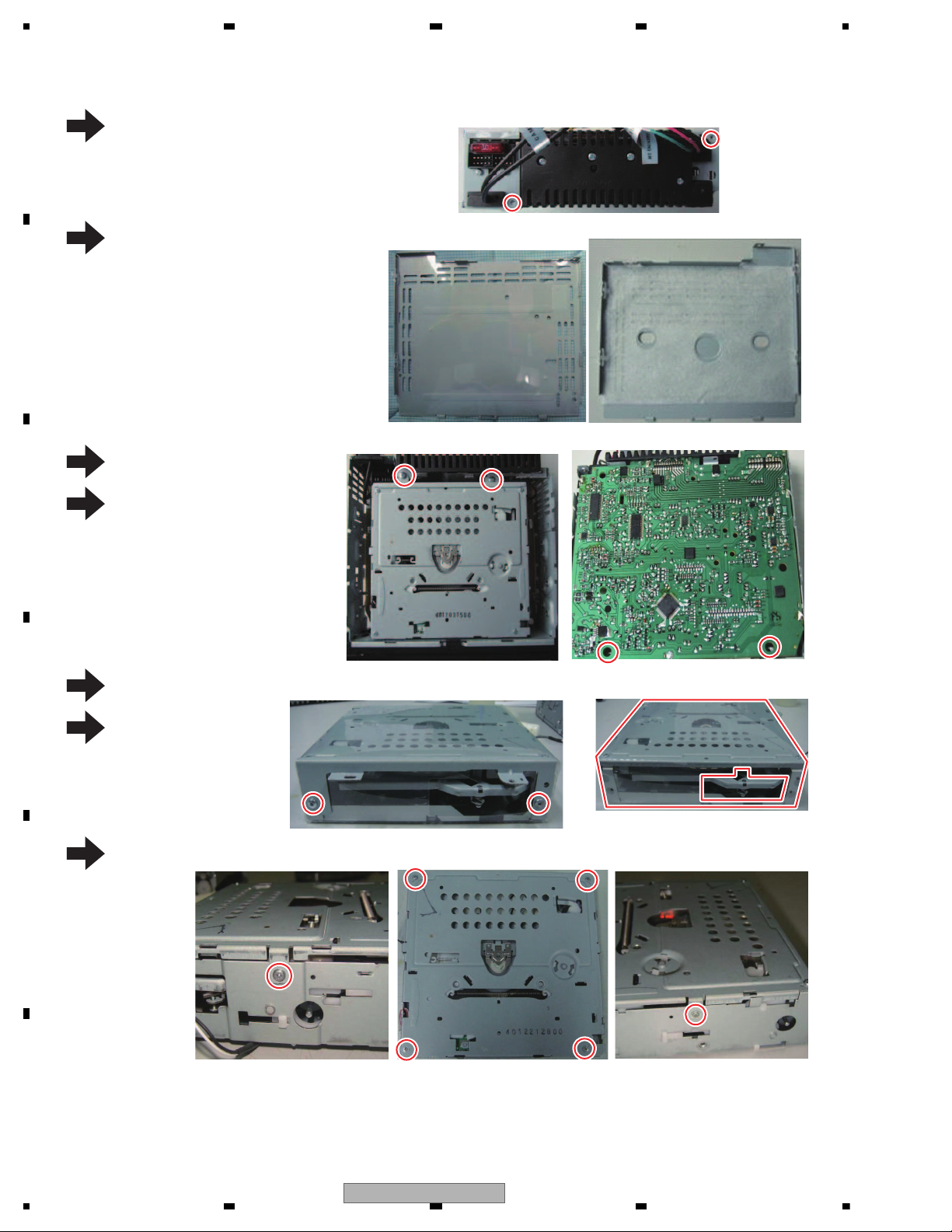
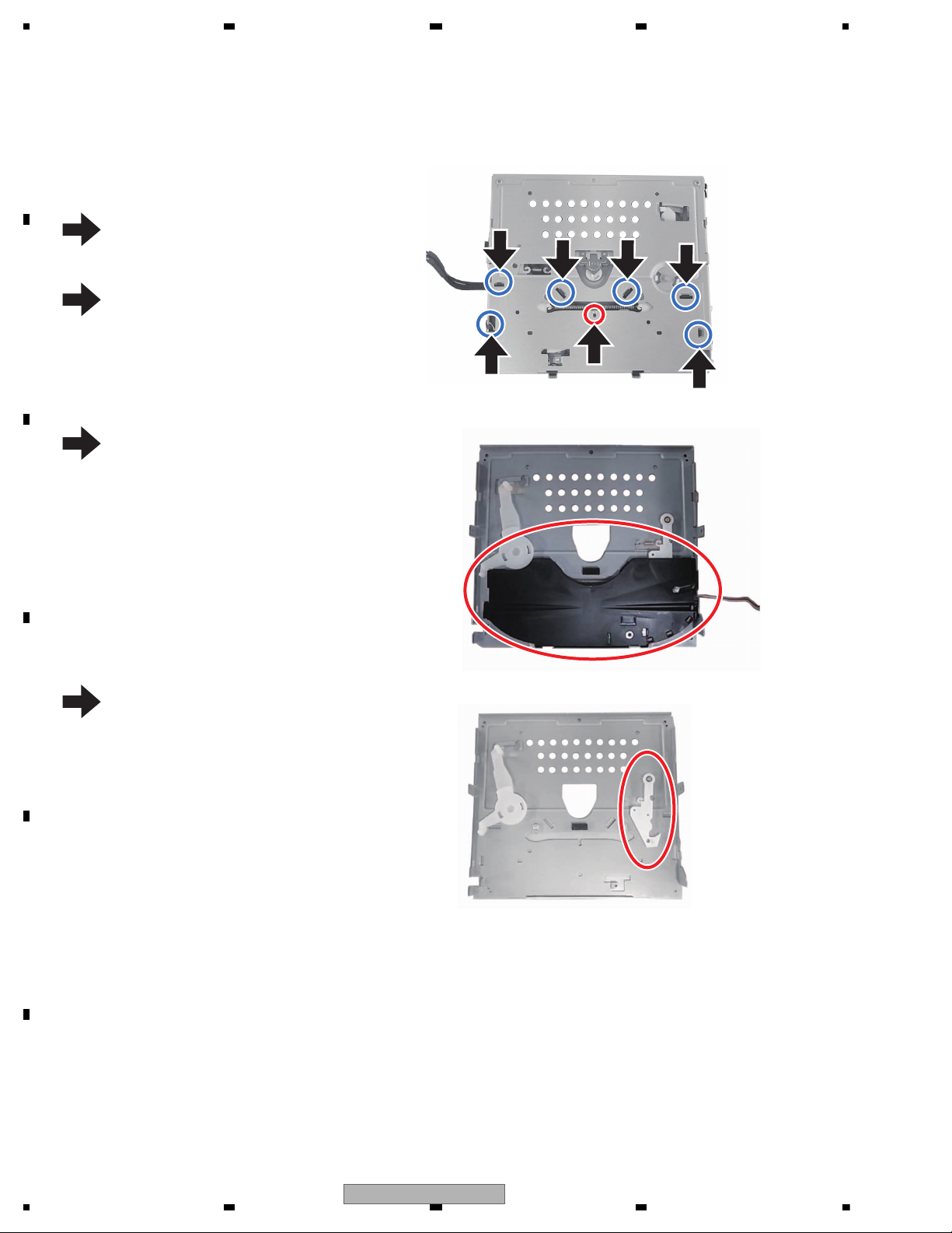
Removing the lever located at the reverse side of DVD mechanism's top cover
Remove the black lever holder.
2
Remove the top cover according to "How to eject the stuck disc (Procedure 2: Removing the top cover)" on the page 21.
Remove the one screw.
Remove the lever.
4
Remove the six hooks.
1
2
2
2
2
2
2
24
DVH-750AV/XEUW5

5 678
56
7
8
C
D
F
A
B
E
8. EACH SETTING AND ADJUSTMENT
There is no information to be shown in this chapter.
DVH-750AV/XEUW5
25
1234
1234
C
D
F
A
B
E
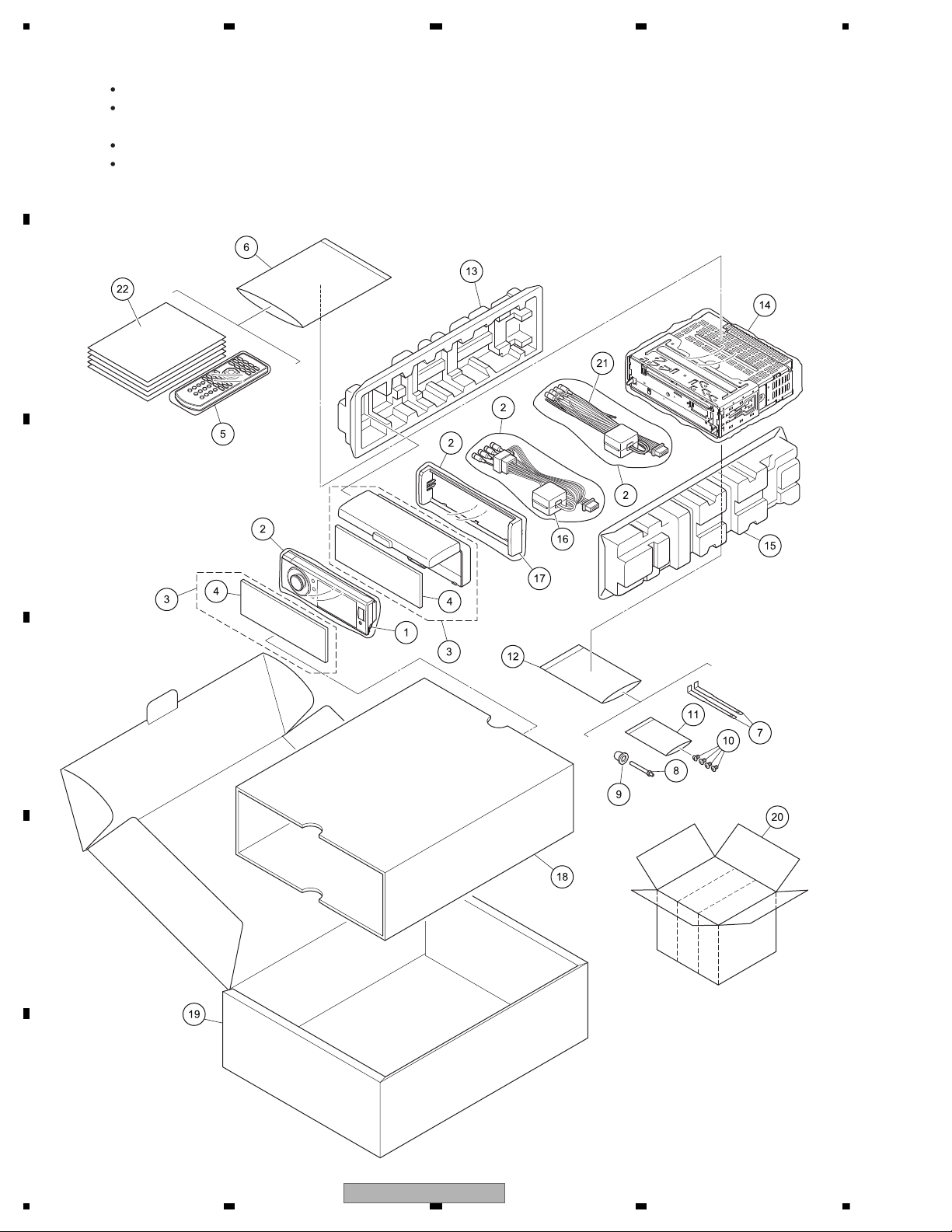
9. EXPLODED VIEWS AND PARTS LIST
N
-1
UW5, RD, RI
UW5, BR
RD, RI
-2
OTES : Parts marked by " * " are generally unavailable because they are not in our Master Spare Parts List.
The > mark found on some component parts indicates the importance of the safety factor of the part.
Therefore, when replacing, be sure to use parts of identical designation.
Screw adjacent to mark on the product are used for disassembly.
For the applying amount of lubricants or glue, follow the instructions in this manual.
(In the case of no amount instructions,apply as you think it appropriate.)
9.1 PACKING
"
26
DVH-750AV/XEUW5
 Loading...