

Pioneer DEH P4800MP User Manual

MAN-DEH-P4800MP-GB.fm Page 1 Thursday, September 29, 2005 11:55 AM
.
Multi-CD control High power CD/MP3/WMA player with RDS tuner
Operation Manual
DEH-P4800MP
Visit www.pioneer.co.uk (or www.pioneer-eur.com)
to register your product
Q sound.vision.soul
ENGLISH

MAN-DEH-P4800MP-GB.fm Page 2 Thursday, September 29, 2005 11:55 AM
Contents
Thank you for buying this Pioneer product
Please read through these operating instructions so you will know how to operate your
model properly. After you have finished reading the instructions, keep this manual in a
safe place for future reference.
Connecting the Units ........................... 3
Installation ............................................ 5
DIN Front/Rear-mount ............... ................. 5
DIN Front-mount ..................................... .... 5
* Installation with the rubbe r bush ........... 5
* Removing the Unit ................................ 5
DIN Rear-mount .......................................... 5
* Installation using the sc rew
holes on the side of the u nit .................. 5
Fixing the front panel .......... ........................ 6
Before You Start ................................... 6
About this unit ......................................... .... 6
About this manual ................................... .... 7
In case of trouble ................ ........................ 7
Features ........................ .............................. 7
About WMA ................................ ................. 7
Visit our website .......................................... 7
Protecting your unit from theft .... ................. 8
* Removing the front panel ..................... 8
* Attaching the front panel ....................... 8
What’s What .......................................... 8
Head unit ................ ..................................... 8
Optional remote control ........................... .... 9
Power ON/OFF ...................................... 9
Turning the unit on ...................................... 9
Selecting a source ..................... ................. 9
Turning the unit off ...................................... 9
Tuner ................................................... 10
Listening to the radio ................................. 10
Introduction of advanc ed tuner
operation .......................... ...................... 10
Storing and recalling broadcast
frequencies ....................... ...................... 10
Tuning in strong signals ............................ 11
Storing the stronges t broadcast
frequencies ....................... ...................... 11
RDS ..................................................... 11
Introduction of RDS oper ation .................. 11
Switching the RDS display ........................ 12
Selecting alternative freq uencies .. ............ 12
* Using PI Seek ............ ......................... 12
* Using Auto PI Seek for
preset stations ............................... ..... 12
* Limiting stations to regi onal
programming .................... .................. 12
Receiving traffic announ cements .............. 12
Receiving PTY alarm br oadcasts ............. 13
PTY list ......................................... ............ 13
Built-in CD Player ............................... 14
Playing a CD ........................................ ..... 14
Introduction of advance d built-in
CD player operation ............................... 14
Repeating play ..................................... ..... 14
Playing tracks in rando m order ................. 15
Scanning tracks of a CD ........................... 15
Pausing CD playback ................... ............ 15
Using compression and BMX ................... 15
Selecting the search me thod .................... 15
Searching every 10 tr acks in the
current disc .............. ............................... 15
Using disc title functions ........................... 16
* Entering disc titles .............................. 16
* Displaying disc titles ........................... 16
Using CD TEXT functions ....... .................. 16
* Displaying text information on
CD TEXT discs ................................... 16
* Scrolling text informa tion
in the display .......................... ............ 16
MP3/WMA/WAV Player ...................... 17
Playing MP3/WMA/WAV ........................... 17
Introduction of advance d built-in CD
player (MP3/WMA/WAV) op eration ........ 17
Repeating play ..................................... ..... 18
Playing tracks in rando m order ................. 18
Scanning folders and tracks ..................... 18
Pausing MP3/WMA/WA V playback .......... 1 8
Using compression and BMX ................... 19
Selecting the search me thod .................... 19
Searching every 10 tr acks in the
current folder .......................................... 19
Displaying text infor mation on
MP3/WMA/WAV disc ................. ............ 19
* When playing back an
MP3/WMA disc .............................. ..... 1 9
* When playing back a W AV disc ......... 20
Scrolling text informatio n in the display .... 20
Multi-CD Player ................................... 20
Playing a CD .... ........................................ . 20
50-disc multi-CD player .................... ........ 21
Introduction of advanced multi-CD
player operation ................ ..................... 21
Repeating play .................................. ........ 21
Playing tracks in random order ................. 21
Scanning CDs and tracks ......................... 21
Pausing CD playback ....................... ........ 22
Using ITS playlists .................................... 22
* Creating a playlist with ITS
programming ................. ..................... 22
* Playback from your ITS p laylist .......... 22
* Erasing a track from your
ITS playlist .................................. ........ 22
* Erasing a CD from yo ur
ITS playlist .................................. ........ 23
Using disc title functions ........................... 23
* Entering disc titles .............................. 23
* Displaying disc titles ........................... 23
Using CD TEXT functions ......................... 23
* Displaying text inform ation on
CD TEXT discs ................................... 24
* Scrolling text informati on
in the display ....................... ............... 24
Using compression and ba ss
emphasis .................... ............................ 24
Audio Adjustments ............................. 24
Introduction of audio adju stments ..... ........ 24
Using balance adjustment ................ ........ 25
Using the equalizer ........................... ........ 25
* Recalling equalizer cur ves ................. 25
* Adjusting equalizer cur ves ................. 25
* Fine-adjusting equali zer curve ........... 26
Adjusting loudness ........ ............................ 26
Using subwoofer output ............................ 26
* Adjusting subwoofer settings ...... ........ 27
Using the high pass filter .................. ........ 27
Boosting the bass ..................................... 27
Front image enhancer (F.I. E.) ................... 27
Adjusting source levels ............................. 28
Initial Settings ..................................... 28
Adjusting initial settings ............................ 28
Setting the FM tuning step ....................... 28
Switching Auto PI Seek ............................ 29
Switching the auxiliary setting .................. 29
Setting the rear output and subwoofer
controller .............................. .................. 29
Saving the battery cons umption ............... 29
Other Functions .................................. 30
Using the AUX source .............................. 30
* About AUX1 and AUX2 ...................... 30
* Selecting AUX as the sou rce ............. 30
* Setting the AUX title ........................... 30
Additional Information ....................... 31
Understanding built-in CD player
error messages ...................................... 31
Sound muting ................................ ........... 31
CD player and care ... ............................... 31
CD-R/CD-RW discs .................................. 31
MP3, WMA and WAV files ................... ..... 32
* MP3 additional informati on ................. 32
* WMA additional informat ion ............... 32
* WAV additional informa tion ................ 33
About folders and MP3/WMA/WAV files ... 33
Terms ............................... ........................ 33
Specifications ................... ........................ 34
2
ENGLISH
MAN-DEH-P4800MP-GB.fm Page 3 Thursday, September 29, 2005 11:55 AM
Connecting the Units
Notes
• This unit is for vehicles wit h a 12-volt battery and negativ e grounding. Before install ing it in
a recreational vehicle, tr uck, or bus, check the battery voltage.
• To avoid shorts in the e lectrical system, be sure to di sconnect the - battery cable before
beginning installatio n.
• Refer to the owner’s manual for de tails on connecting the power amp and other units, then
make connections corr ectly.
• Secure the wiring with cable c lamps or adhesive tape. To prote ct the wiring, wrap adhesive
tape around them wher e they lie against metal par ts.
• Route and secure all wir ing so it cannot touch any m oving parts, such as the g ear shift,
handbrake and seat rails. Do not route wiring in places that get hot, such as near the heater
outlet. If the insulation o f the wiring melts or gets torn, there is a danger of th e wiring shortcircuiting to the vehic le body.
• Do not pass the yellow l ead through a hole into the engine compartment to co nnect to the
battery. This will dama ge the lead insulation and cause a very dangerous s hort.
• Do not shorten any leads . If you do, the protection circuit may fail to work when it should.
• Never feed power to other equipment by cutting the insulation of the power supp ly lead of
the unit and tapping into the lead. The current capac ity of the lead will be exceeded, causing
overheating.
• When replacing the fus e, be sure to only use a fu se of the rating prescri bed on this product.
• Since a unique BPTL circuit is employed, neve r wire so the speaker leads are directly
grounded or the left and right - speaker leads are common.
• Speakers connected to th is unit must be highpower with minimum rating of 5 0 W and
impedance of 4 to 8 ohms. Connecting spe akers with output and/or impedance values other
than those noted here may result in the speakers catching fire, emi tting smoke or becoming
damaged.
• When this product’s sourc e is switched ON, a control signal is output thro ugh the blue/white
lead. Connect to an ex ternal power amp’s system r emote control or the car ’s Auto-antenna
relay control terminal (max. 3 00 mA 12 V DC). If the car features a glass antenna, connect
to the antenna booster power supply terminal.
• When an external power amp is being used with this system, be sure not to connect the blue/
white lead to the amp’s power termin al. Likewise, do not connect the blue/white lead to the
power terminal of the a uto-antenna. Such connec tion could cause excessi ve current drain
and malfunction.
• To avoid short-circuiti ng, cover the disconnected lead with insulating tape. Insulate the
unused speaker l eads without fail. Th ere is a possibility of a short-circuiting if the leads are
not insulated.
• To prevent incorrect c onnection, the input side of the IP-BUS connector i s blue, and the
output side is black. Co nnect the connectors of t he same colors correctly.
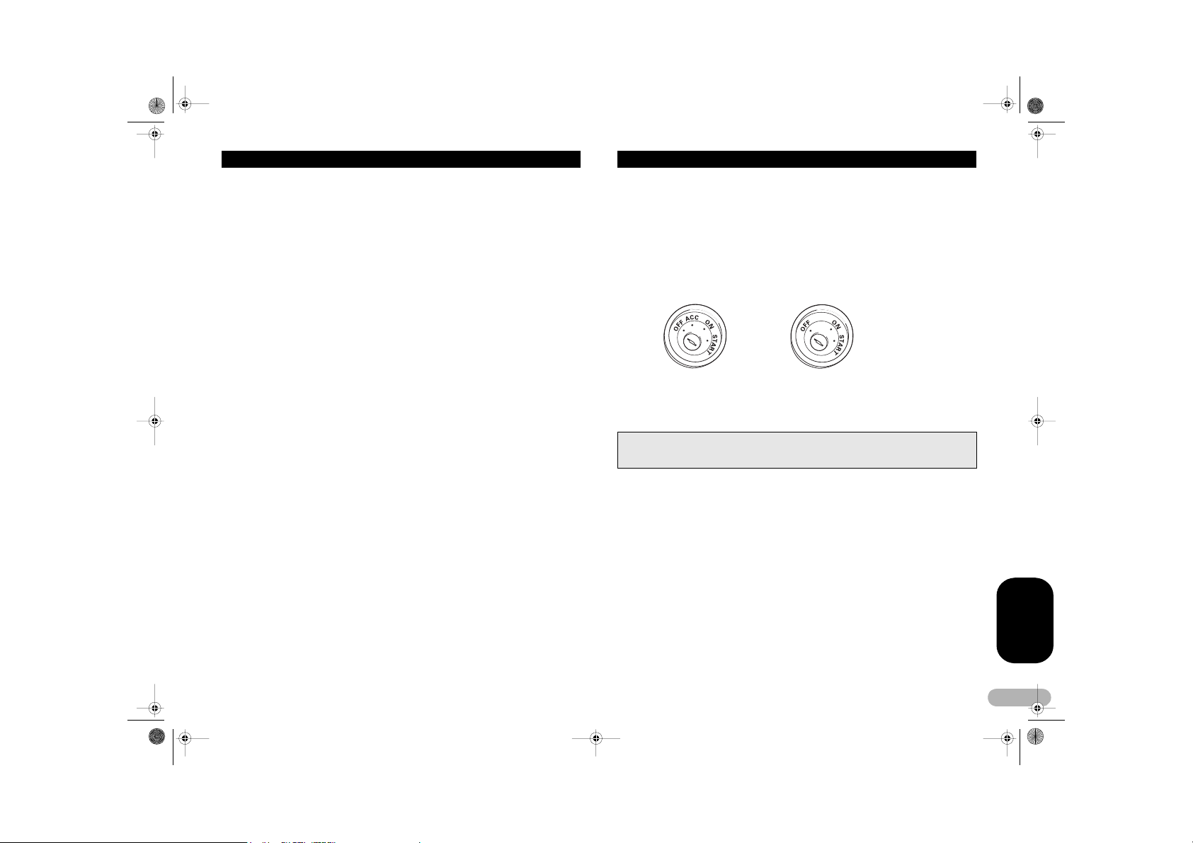
• If this unit is installe d in a vehicle that does not have an ACC (accessory) position on the
ignition switch, the red lead of the unit should be connected to a terminal c oupled with
ignition switch ON/OF F operations. If this is not done, the vehicle battery m ay be drained
when you are away from the vehicle for severa l hours.
ACC position No ACC position
• The black lead is ground. P lease ground this lead separately from the ground of high-current
products such as power amps.
If you ground the pr oducts together and the gr ound becomes detached, t here is a risk of
damage to the produc ts or fire.
• Cords for this product an d those for other products may be different colors ev en if they have
the same function. When connecting this produ ct to another product, refer to the supplied
manuals of both pro ducts and connect cords t hat have the same function .
ENGLISH
3
MAN-DEH-P4800MP-GB.fm Page 4 Thursday, September 29, 2005 11:55 AM
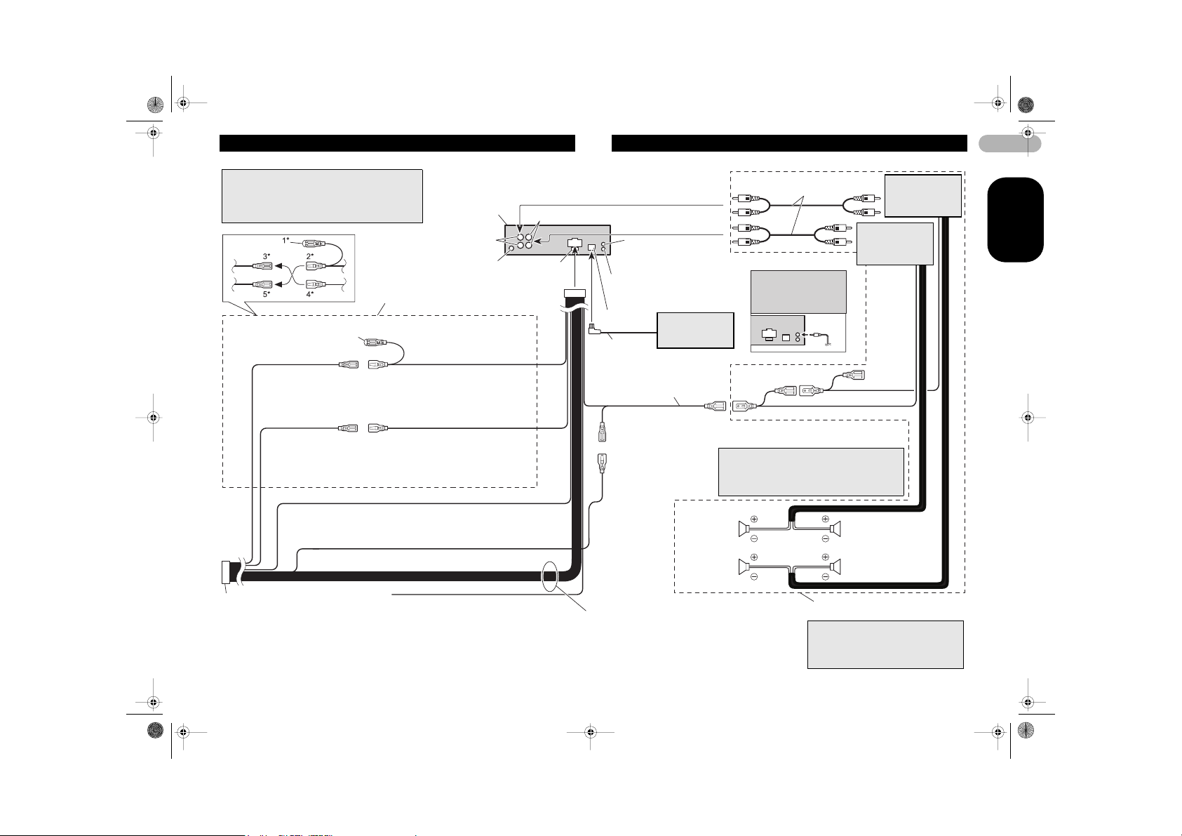
Connecting the Units
Note
Depending on the kind of vehicle, the function of 3*
and 5* may be different. In this case, be sure to
connect 2* to 5* and 4 * to 3*.
Connect leads of the same
color to each other.
Cap (1*)
When not using this
terminal, do not remo ve
the cap.
Back-up (or accessory)
Accessory (or back-up)
ISO connector
Note
In some vehicles, the ISO conne ctor may be
divided into two. In this c ase, be sure to
connect to both conne ctors.
Yellow (3*)
Yellow (2*)
To terminal always suppl ied with
power regardless of ignition switch
position.
Red (5*)
Red (4*)
To electric terminal c ontrolled by
ignition switch (12 V DC ) ON/OFF.
Black (ground)
To vehicle (metal) b ody.
This product
Subwoofer output or
Rear output
Antenna jack
Yellow/black
If you use a cellular tel ephone, connect it via
the Audio Mute lead on the cellular tele phone.
If not, keep the Audio Mute lead free of any
connections.
Front output
Fuse (10 A)
AUX jack (3.5 ø)
Jack for Wired Remote Co ntrol
Please see the Instruc tion Manual
for the Wired Remote Cont rol (sold
separately).
IP-BUS input
(Blue)
IP-BUS cable
Blue/white
To system control termin al of the
power amp (max. 300 mA 1 2 V DC).
Blue/white (7*)
To Auto-antenna rela y control
terminal (max. 300 mA 1 2 V DC).
Blue/white (6*)
Speaker leads
White: Front left +
White/black: Front left Gray: Front right +
Gray/black: Front right Green: Rear left + or Subwoofer +
Green/black: Rear left - or Subwoofer Violet: Rear rig ht + or Subwoofer +
Violet/black: Rear right - or Su bwoofer -
Mult-CD player
(sold separately)
The pin position of the I SO connector will differ
The pin position of the I SO connector will differ
depends on the type of vehi cle. Connect 6* and 7*
depends on the type of vehi cle. Connect 6* and 7*
when Pin 5 is an ant enna control type. In another
when Pin 5 is an ant enna control type. In another
type of vehicle, never c onnect 6* and 7*.
type of vehicle, never c onnect 6* and 7*.
Front speaker Front speaker
Left
Subwoofer or
Rear speaker
Connecting cords with RCA p in
plugs (sold separately)
Note
Use a stereo mini plug
cable to connect with
auxiliary equipment .
System remote control
Perform these conne ctions when
using the optional amplifier.
Note
Change the initial settin g of this unit (refer
to the Operation Manual). The subwoofer
output of this unit is mona ural.
Power amp
(sold separately)
Right
Subwoofer or
Rear speaker
Power amp
(sold separately)
4
ENGLISH
MAN-DEH-P4800MP-GB.fm Page 5 Thursday, September 29, 2005 11:55 AM
Installation
Notes
• Before making a final ins tallation of the unit, tempo rarily connect the wiring to c onfirm that
the connections are c orrect and the system work s properly.
• Use only the parts inclu ded with the unit to ensure proper installation. The use of
unauthorized parts can c ause malfunctions.
• Consult with your neares t dealer if installation requ ires the drilling of holes or other
modifications of the ve hicle.
• Install the unit where i t does not get in the driver ’s way and cannot injure th e passenger if
there is a sudden stop , like an emergency stop.
• The semiconductor laser will be damaged if it ov erheats, so don’t install the unit anywhere
hot – for instance, near a heater outlet.
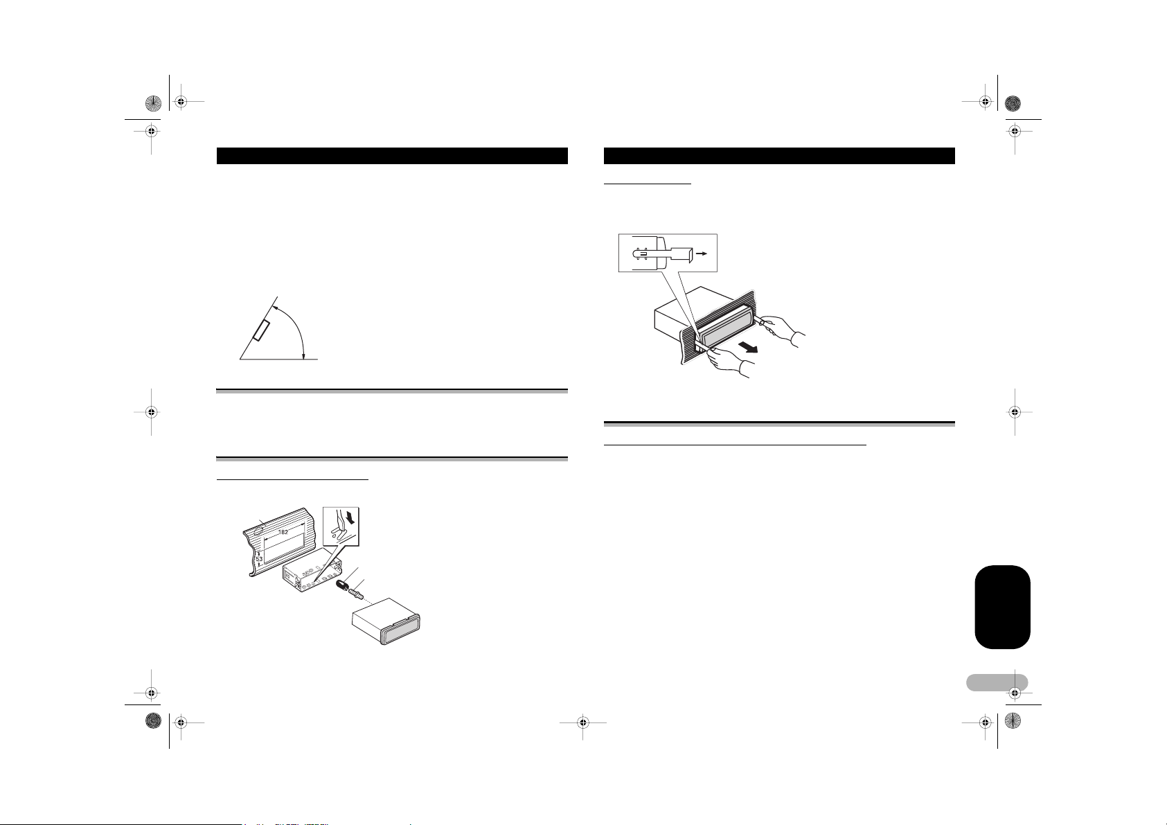
• If installation angle exc eeds 60° from horizontal, th e unit might not give its optimum
performance.
60°
DIN Front/Rear-mount
This unit can be properly installed either from “Front” (conventional DIN Front-moun t)
or “Rear” (DIN Rear-mount installation, utilizing threaded screw holes at the sides of
unit chassis). For details, refer to the following illustrated installation methods.
DIN Front-mount
Installation with the rubber bush
Holder
Dashboard
After inserting the holde r into the dashboard, then select
the appropriate tabs ac cording to the thickness of t he
dashboard material an d bend them.
(Install as firmly as pos sible using the top and b ottom
tabs. To secure, bend the t abs 90 degrees.)
Rubber bush
Screw
Removing the Unit
To remove the frame, e xtend top and bottom of the frame outwards in order to unlock
it. (When reattaching the frame, point the side with a groove downwards and attach it.)
• It becomes easy to remove the frame if the front panel is released.
Insert the supplied extraction keys int o the unit, as shown
in the figure, until they cl ick into place. Keeping th e keys
pressed against the sides of the unit, pull the unit o ut.
DIN Rear-mount
Installation using the screw holes on the side of the unit
1. Remove the frame.
To remove the frame, e xtend top and bottom of the frame outwards in order to unlock
it. (When reattaching the frame, point the side with a groove downwards and attach it.)
• It becomes easy to remove the frame if the front panel is released.
ENGLISH
5
MAN-DEH-P4800MP-GB.fm Page 6 Thursday, September 29, 2005 11:55 AM
Installation
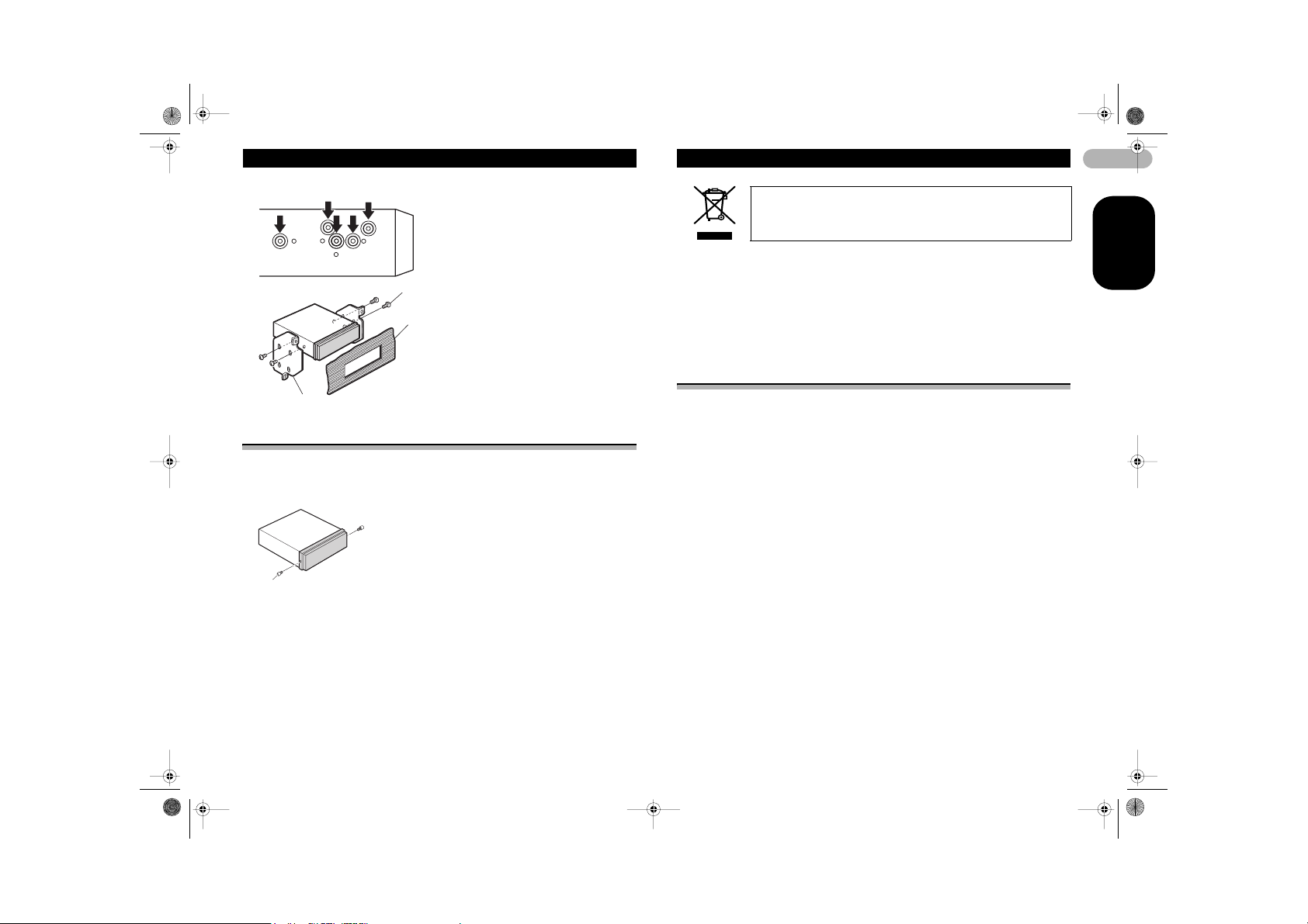
2. Fastening the unit to the factor y radio mounti ng bracket.
Select a position wher e the screw holes of the bracket
and the screw holes of the head unit become align ed
(are fitted) and tighten the sc rews at 2 places on each
side. Use either truss screws (5 x 8 mm) or flush
surface screws (5 x 9 mm), depending on the shape of
the screw holes in the bracket.
Screw
Dashboard or Console
Factory radio mounting bracket
Fixing the front panel
If you do not operate the Removing and Attaching the Front Panel Function, use the
supplied fixing screws and fix the front panel to this unit.
1. Fix the front panel to the unit using fixing screws.
Fixing screw
Before You Start
If you want to dispose this product, do not mix it with general household
waste. There is a separate collection system for used electronic
products in accordance with legislation that requires proper treatment,
recovery and recycling.
Private households in the 25 member states of the EU, in Switzerland and Norway
may return their used electronic products free of charge to designated collection
facilities or to a retailer (if you purchase a similar new one).
For countries not mentioned above, please contact your local authorities for the correct
method of disposal.
By doing so you will ensure that your disposed product undergoes the necessary
treatment, recovery and recycling and thus prevent potential negative effects on the
environment and human health.
About this unit
The tuner frequencies on this unit are allocated for use in Western Europe, Asia, the
Middle East, Africa and Oceania. Use in other areas may result in poor reception. The
RDS (radio data sy stem) function operates only in areas wit h FM stations broadcasting
RDS signals.
! CAUTION
• Do not allow this unit to come into contact with liquids. Electrical shock could result.
Also, this unit damage, smoke, and overheat could result from contact with liquids.
• “CLASS 1 LASER PRODUCT”
• This product contains a laser diode of higher class than 1. To ensure continued
safety, do not remove any covers or attempt to gain access to the inside of the
product. Refer all servicing to qualified personnel.
• The Pioneer CarStereo-Pass is for use only in Germany.
• Keep this manual handy as a reference for operating procedures and precautions.
• Always keep the volume low enough so that you can hear sounds from outside the
vehicle.
• Protect this unit from moisture.
• If the battery is disconnected or discharged, the preset memory will be erased and
must be reprogrammed .
6
ENGLISH
MAN-DEH-P4800MP-GB.fm Page 7 Thursday, September 29, 2005 11:55 AM
Before You Start
About this manual
This unit features a number of sophisticated functions ensuring superior rece ption and
operation. All the functions have been designed for the easiest possible use, but many
are not self-explanatory. This operation manual will help you benefit fully from this
unit’s potential and to maximize your listening enjoyment.
We recommend that you familiarize yourself with the functions and their operation by
reading through the manual before you begin using this unit. It is especially important
that you read and observe WARNINGs and CAUTIONs in this manual.
In case of trouble
Should this product fail to operate properly, contact your dealer or nearest authorized
Pioneer Service Station.
Features
CD playback
Music CD/CD-R/CD-RW playback is possible.
MP3 file playback
You can play back MP3 files recorded on CD-ROM/CD-R/CD-RW (ISO9660 Level 1/
Level 2 standard recordings).
• Supply of this product only conveys a license for private, non-commercial use and
does not convey a license nor imply any right to use this product in any commercial
(i.e. revenue-generating) real time broadcasting (terrestrial, satellite, cable and/or
any other media), broadcasting/streaming via internet, intranets and/or other
networks or in other electronic content distribution s ystems, such as pay-audio o r
audio-on-demand applications. An independent license for such use is required. For
details, please visit http://www.mp3licensing.com.
WMA file playback
You can play back WMA files recorded on CD-ROM/CD-R/CD-RW (ISO9660 Level 1/
Level 2 standard recordings).
WAV file playback
You can play back WAV files recorded on CD-ROM/CD-R/CD-RW (ISO9660 Level 1/
Level 2 standard recordings).
About WMA
The Windows Media™ logo printed on the box indicates that this unit can play back
WMA data.
WMA is short for Windows Media™ Audio and refers to an audio compression
technology that is developed by Microsoft Corporation. WMA data can be encoded by
using Windows Media Player version 7 or later.
Windows Media and the Windows logo are trademarks or registered trademarks of
Microsoft Co rporation in the United States and/or other countries.
Notes
• This unit may not operate correctly depending on the a pplication used to encode WMA files.
• Depending on the ver sion of Windows Media Pla yer used to encode WMA files, album
names and other text information may not be correctly displayed.
• There may be a s light delay when startin g playback of WMA file s encoded with image d ata.
Visit our website
Visit us at the following site:
• Register your product. We will keep the details of your purchase on file to help you
refer to this information in the eve nt of an insurance claim s uch as loss or theft.
• We offer the latest information about Pioneer Corporation on our website.
ENGLISH
7
MAN-DEH-P4800MP-GB.fm Page 8 Thursday, September 29, 2005 11:55 AM
Before You Start
Protecting your unit from theft
The front panel can be detached from the head unit and stored in the provided
protective case to prevent theft.
Important
• Never use force or grip the display and the buttons too tightly when removing or
attaching.
• Avoid subjecting the front panel to excessive shocks.
• Keep the front panel out of direct sunlight and high temperatures.
Removing the front panel
1. Press DETACH to release the front panel.
Press DETACH and the right side of the panel is released from the head unit.
2. Grab the front pan el and remove.
Grab the right side of the front panel and pull away to the left. The front panel will be
detached from the head unit.
3. Put the front panel into provided protective case for safe keeping.
Attaching the front panel
1. Place the front panel flat against the head unit.
2. Press the front panel into the face of the head unit until it is firmly seated.
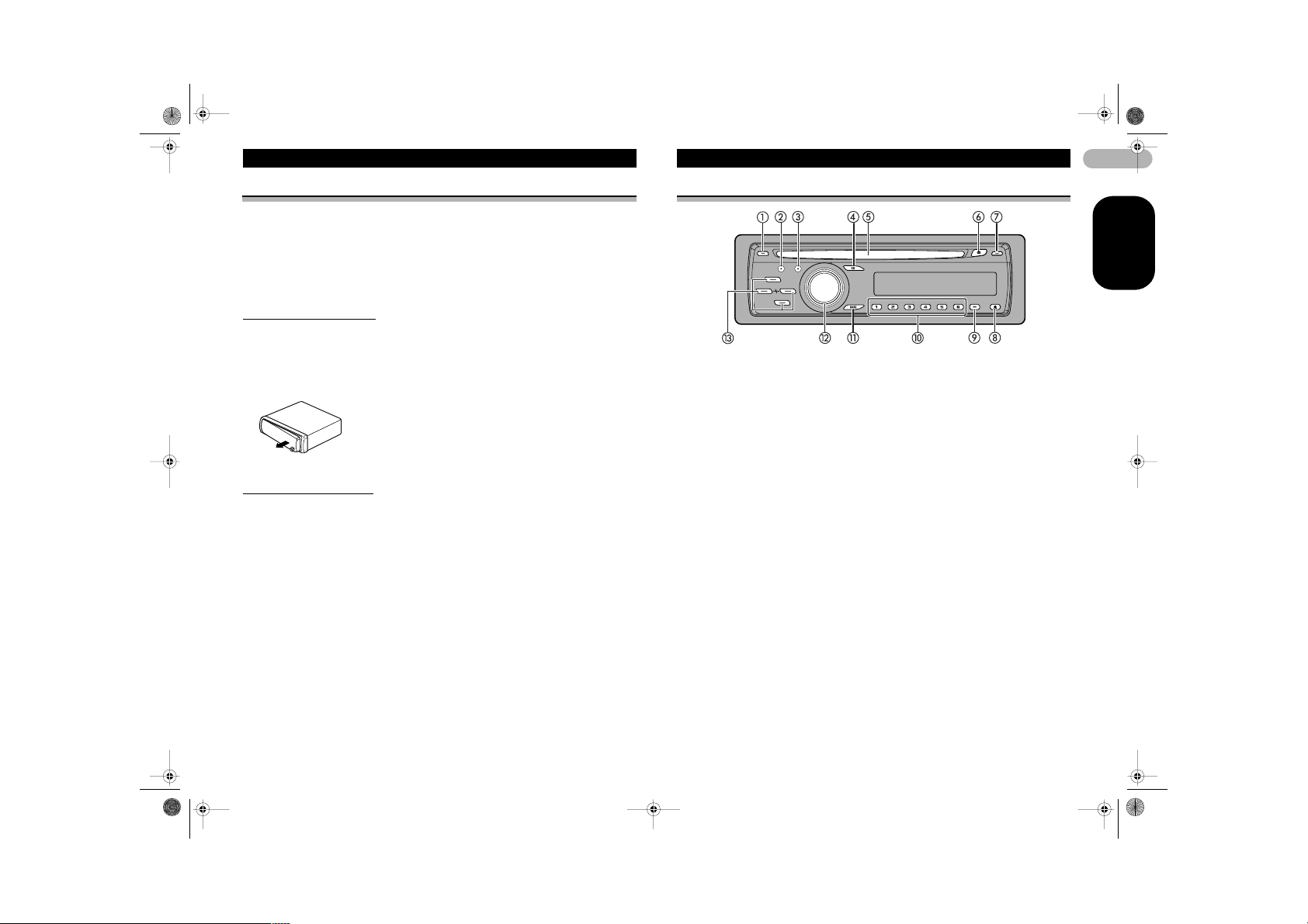
What’s What
Head unit
햲 TA button
Press to turn TA function on or off.
Press and hold to turn AF function
on or off.
햳 AUDIO button
Press to select various sound quality
controls.
햴 FUNCTION button
Press to select functions.
햵 EQ button
Press to select various equalizer
curves.
햶 Disc loading slot
Insert a disc to play.
햷 EJECT button
Press to eject a CD from your built-in
CD player.
햸 DISPLAY button
Press to select different displays.
햹 DETACH button
Press to remove the front panel from
the head unit.
햺 SW button
Press to select the subwoofer setting
menu. Press and hold to select the
bass boost setting menu.
햻 1–6 buttons
Press for preset tuning and disc
number search when using a multiCD player.
햽 BAND button
Press to select among three FM
bands and MW/L W bands and to
cancel the control mode of functions.
햾 SOURCE button, VOLUM E
This unit is turned on by selecting a
source. Press to cycle through all the
available sources.
Rotate it to increase or decrease the
volume.
햿 8/2/4/6 buttons
Press to perform manual seek tuning,
fast forward, reverse and track search
controls. Also used for controlling
functions.
8
ENGLISH
MAN-DEH-P4800MP-GB.fm Page 9 Thursday, September 29, 2005 11:55 AM
What’s What
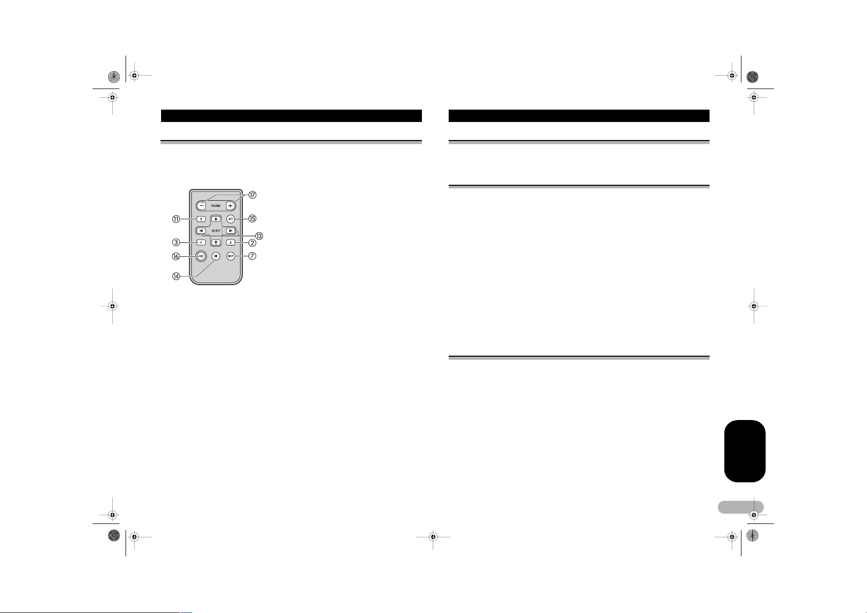
Optional remote control
The remote control CD-R310 is sold separately.
Operation is the same as when using the buttons on the head unit. See the explanation
of the head unit about the operation of each button with the exception of ATT, which
is explained below.
헀 PAUSE button
Press to turn pause on or off.
헁 ATT button
Press to quickly lower the volume level, by about 90%. Press once more
to return to the original volume level.
헂 SOURCE button
Press to cycle through all the available sources. Press and hold to turn
the source off.
헃 VOLUME button
Press to increase or decrease the volume.
Power ON/OFF
Turning the unit on
* Press SOURCE to turn the unit on.
When you select a source, the unit is turned on.
Selecting a source
You can select a source you want to listen to. To switch to the built-in CD player, load
a disc in the unit (refer to page 14).
* Press SOURCE to select a source.
Press SOURCE repeatedly to switch between the following sources:
Tuner – Television – Built-in CD player – Multi-CD player – External unit 1 –
External unit 2 – AUX1 – AUX2
Notes
• In the following cases , the sound source will not change:
– When there is no unit cor responding to the selected source connected to thi s unit.
– When there is no disc in the unit.
– When there is no magazine in the multi-CD player .
– When the AUX (auxiliary i nput) is set to off (refer to p age 29).
• External unit refers to a Pioneer product (suc h as one available in the fu ture) that, although
incompatible as a sou rce, enables control of ba sic functions by this unit. Two e xternal units
can be controlled by this un it. When two external units are connected, the allocation of them
to external unit 1 or external unit 2 is automati cally set by this unit.
• When this unit’s blue/wh ite lead is connected to the vehicle’s auto-antenna relay control
terminal, the vehicle’ s antenna extends when this unit’s source is turned on. To retract the
antenna, turn the sou rce off.
Turning the unit off
* Press SOURCE and hold until the unit turns off.
ENGLISH
9
MAN-DEH-P4800MP-GB.fm Page 10 Thursday, September 29, 2005 11:55 AM
Tuner
Listening to the radio
These are the basic steps necessary to operate the radio. More advanced tuner
operation is explained starting on this page.
This unit’s AF (alternative frequencies search) function can be turned on and off. AF
should be off for normal tuning operation (refer to page 12).
햲 Band indicator
Shows which band the radio is
tuned to, MW/LW or FM.
햳 Preset number indicator
Shows which preset has been
selected.
햴 Frequency indicator
Shows the frequency to which the
tuner is tuned.
햵 Stereo (%) indicator
Shows when the selected
frequency is being broadcast in
stereo.
1. Press SOURCE to select the tuner.
Press SOURCE until you see TUNER displayed.
2. Use VOLUME to adjust the sound level.
Rotate it to increase or decrease the volume.
3. Press BAND to select a band.
Press BAND until the desired band is displayed, FM1, FM2 for FM or MW/LW.
4. To perform manual tuning, briefly pres s 4 or 6.
The frequencies move up or down step by step.
5. To perform seek tuning, press and hold 4 or 6 for about one second and
release.
The tuner will scan the frequencies until a broadcast strong enough for good reception
is found.
• You can cancel seek tuning by briefly pressing 4 or 6.
• If you press and hold 4 or 6 you can skip stations. Seek tuning sta rts as soon as
you release the button.
Note
• When the frequency selected is being broadcast in stereo the stereo ( %) indicator will light.
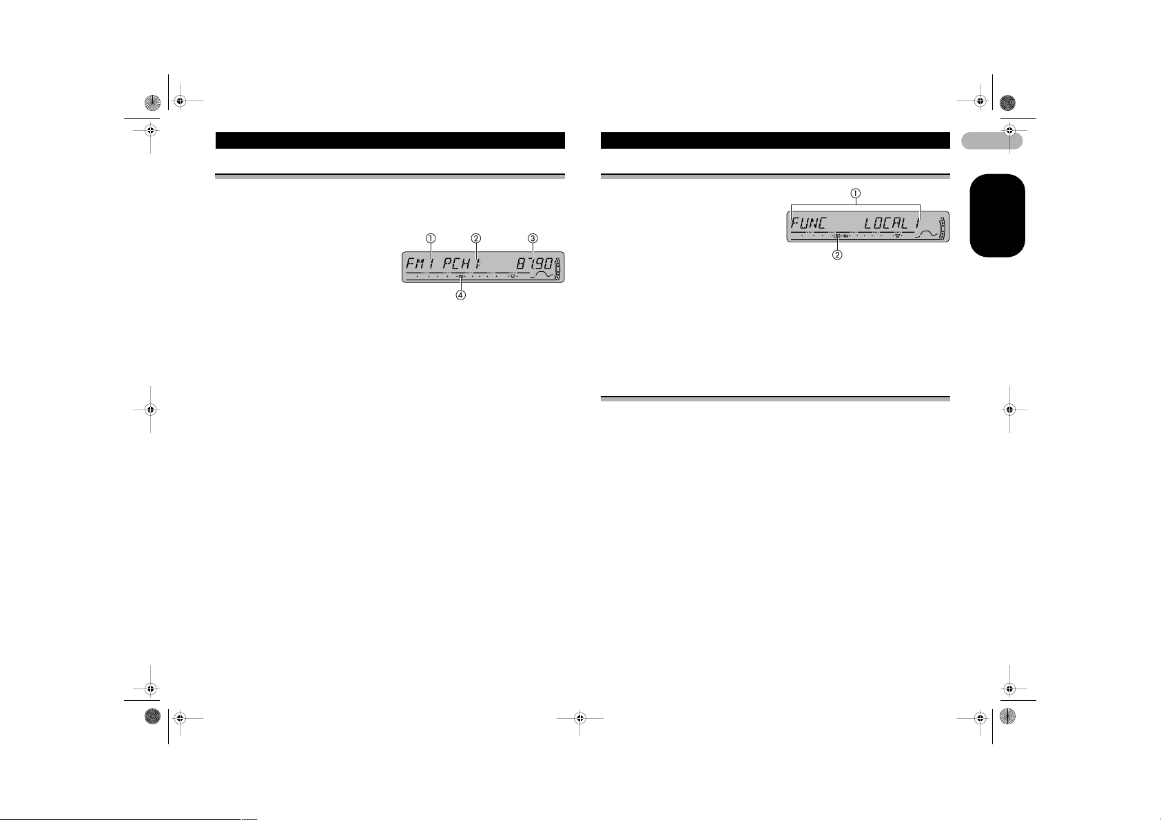
Introduction of advanced tuner operation
햲 Function display
Shows the function status.
햳 LOC indicator
Shows when local seek tuning is
on.
* Press FUNCTION to display the
function names.
Press FUNCTION repeatedly to switch between the following functions:
BSM (best stations memory) – REG (regional) – LOCAL (local seek tuning) – TA
(traffic announcement standby) – AF (alternative frequencies search)
• To return to the frequency display, press BAND.
• If MW/LW band is selected, you can only select BSM or LOCAL.
Note
• If you do not operate the function within about 30 seconds, the display is automatically
returned to the frequen cy display.
Storing and recalling broadcast frequencies
If you press any of the preset tuning buttons 1–6 you can easily store up to six
broadcast frequencies for later recall with the touch of a button.
* When you find a frequency that you want to store in memory, press one of preset
tuning buttons 1–6 and hold until the preset number stops flashing.
The number you have pressed will flash in the preset number indicator and then
remain lit. The selected radio station frequency has been stored in memory.
The next time you press the same preset tuning button the radio station frequency is
recalled from memory.
Notes
• Up to 18 FM stations, s ix for each of the three FM bands, and six MW/LW stations can be
stored in memory.
• You can also use 8 an d 2 to recall radio station f requencies assigned to p reset tuning
buttons 1– 6.
10
ENGLISH
MAN-DEH-P4800MP-GB.fm Page 11 Thursday, September 29, 2005 11:55 AM
Tuner
Tuning in strong signals
Local seek tuning lets you tune in only those radio stations with sufficiently strong
signals for good reception.
1. Press FUNCTION to select LOCAL.
Press FUNCTION until LOCAL appears in the display.
2. Press 8 to turn local seek tuning on.
Local seek sensitivity (e. g., LOCAL 2) appears in the display.
3. Press 4 or 6 to set the sensitivity.
There are four levels of sensitivity for FM and two levels for MW/LW:
FM: LOCAL 1 – LOCAL 2 – LOCAL 3 – LOCAL 4
MW/LW: LOCAL 1 – LOCAL 2
The LOCAL 4 setting allows reception of only the strong est stations, while lower
settings let you receive progressively weaker stations.
4. When you want to return to normal seek tuning, press 2 to turn local seek tuning
off.
LOCAL:OFF appears in the display.
Storing the strongest broadcast frequencies
BSM (best stations memory) lets you automatically store the six strongest broadcast
frequencies under preset tuning buttons 1–6. Once stored you can tune in to those
frequencies with the touch of button.
1. Press FUNCTION to select BSM.
Press FUNCTION until BSM appears in the display.
2. Press 8 to turn BSM on.
BSM begins to flash. While BSM is flashing the six strongest broadcast frequencies
will be stored under preset tuning buttons 1–6 in the order of their signal strength.
When finis hed, BSM stops flashing.
• To cancel the storage process, press 2.
Note
• Storing broadcast frequ encies with BSM may repl ace broadcast frequen cies you have
saved using buttons 1– 6.
RDS
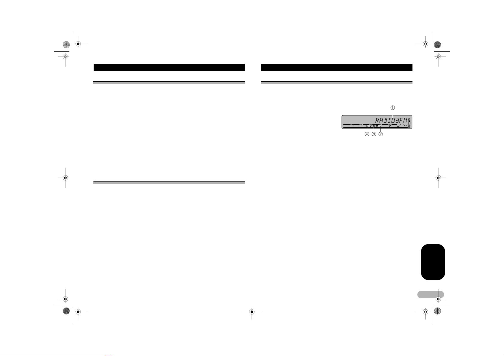
Introduction of RDS operation
RDS (radio data system) is a sy stem for provi ding information along with F M
broadcasts. This inaudible information provides such features as program service
name, program type, traffic announcement standby and automatic tuning, and is
intended to aid radio listeners in finding and tuning in to a desired station.
햲 Program service name
Shows the name of broadcast
program.
햳 TP indicator
Shows when a TP station is tuned
in.
햴 TA :ON indicator
Shows when TA (traffic
announcement standby) function is
on.
햵 AF indicator
Shows when AF (alternative
frequencies search) function is on.
* Press FUNCTION to display the function names.
Press FUNCTION repeatedly to switch between the following functions:
BSM (best stations memory) – REG (regional) – LOCAL (local seek tuning) – TA
(traffic announcement standby) – AF (alternative frequencies search)
• To return to the frequency display, press BAND.
• If MW/LW band is selected, you can only select BSM or LOCAL.
Notes
• If you do not operate the function within about 30 seconds, the display is automatically
returned to the frequen cy display.
• RDS service may no t be provided by all stati ons.
• RDS functions suc h as AF and TA are only ac tive when your radio is tune d to an RDS
station.
ENGLISH
11
 Loading...