

Page 1
English
Español
Deutsch
Français
Italiano
Nederlands
PyТТНЛИ
AVH-P5900DVD
This product conforms to new cord colors.
Los colores de los cables de este producto se conforman con un nuevo código de colores.
Dieses Produkt entspricht den neuen Kabelfarben.
Le code de couleur des câbles utilisé pour ce produit est
nouveau.
Questo prodotto è conforme ai nuovi codici colori.
De kleuren van de snoeren van dit toestel zijn gewijzigd.
INSTALLATION MANUAL
MANUEL D’INSTALLATION
Page 2

1
Contents
Connecting the Units ................................ 1
Connecting the power cord .............................. 3
When connecting to separately sold power
amp ............................................................ 5
When connecting with a rear view camera ...... 7
When connecting with a multi-channel
processor .................................................... 8
Connecting and installing the optical cable
connection box .......................................... 9
When connecting the external video
component and the display ...................... 10
Installation ................................................ 11
DIN Front/Rear-mount .................................... 11
DIN Front-mount ............................................ 12
DIN Rear-mount .............................................. 13
Fastening the front panel ................................ 14
WARNING
• To avoid the risk of accident and the potential
violation of applicable laws, the front DVD or TV
(sold separately) feature should never be used
while the vehicle is being driven. Also, Rear
Displays should not be in a location where it is a
visible distraction to the driver.
• In some countries or states the viewing of
images on a display inside a vehicle even by
persons other than the driver may be illegal.
Where such regulations apply, they must be
obeyed and this unit’s DVD features should
not be used.
CAUTION
• PIONEER does not recommend that
you install or service your display yourself. Installing or servicing the product
may expose you to risk of electric shock
or other hazards. Refer all installation
and servicing of your display to authorized Pioneer service personnel.
• Secure all wiring with cable clamps or
electrical tape. Do not allow any bare
wiring to remain exposed.
• Do not drill a hole into the engine compartment to connect the yellow lead of
the unit to the vehicle battery. Engine
vibration may eventually cause the insulation to fail at the point where the wire
passes from the passenger compartment
into the engine compartment. Take
extra care in securing the wire at this
point.
• It is extremely dangerous to allow the
display lead to become wound around
the steering column or gearshift. Be sure
to install the display in such a way that
it will not obstruct driving.
• Make sure that wires will not interfere
with moving parts of the vehicle, such as
the gearshift, parking brake or seat sliding mechanism.
• Do not shorten any leads. If you do, the
protection circuit may fail to work
properly.
WARNING
LIGHT GREEN LEAD AT POWER CONNECTOR IS DESIGNED TO DETECT PARKED
STATUS AND MUST BE CONNECTED TO
THE POWER SUPPLY SIDE OF THE PARKING BRAKE SWITCH. IMPROPER CONNECTION OR USE OF THIS LEAD MAY VIOLATE APPLICABLE LAW AND MAY
RESULT IN SERIOUS INJURY OR DAMAGE.
Connecting the Units
Page 3
English
Español
Deutsch
Français
Italiano
Nederlands
PyТТНЛИ
2
Note:
• This unit cannot be installed in a vehicle without ACC (accessory) position on the ignition
switch.
• Use this unit in other than the following conditions could result in fire or malfunction.
— Vehicles with a 12-volt battery and negative
grounding.
— Speakers with 50 W (output value) and 4
ohm to 8 ohm (impedance value).
• To prevent short-circuit, overheating or malfunction, be sure to follow the directions below.
— Disconnect the negative terminal of the bat-
tery before installation.
— Secure the wiring with cable clamps or adhe-
sive tape. To protect the wiring, wrap adhesive tape around them where they lie against
metal parts.
— Place all cables away from moving parts,
such as gear shift and seat rails.
— Place all cables away from hot places, such as
near the heater outlet.
— Do not pass the yellow cable through a hole
into the engine compartment to connect to a
battery.
— Cover any disconnected cable connectors
with insulating tape.
— Do not remove RCA caps if RCA cables are
not used.
— Do not shorten any cables.
— Never cut the insulation of the power cable of
this unit in order to share the power to other
equipment. Current capacity of the cable is
limited.
— Use a fuse of the rating prescribed.
— Never wire the speaker negative cable direct-
ly to ground.
— Never band together multiple speaker’s nega-
tive cables.
• Control signal is output through blue/white cable
when this unit is powered on. Connect it to an
external power amp’s system remote control or
the vehicle’s auto-antenna relay control terminal
(max. 300 mA, 12 V DC). If the vehicle is
equipped with a glass antenna, connect it to the
antenna booster power supply terminal.
• Never connect blue/white cable to external
power amp’s power terminal. Also, never connect it to the power terminal of the auto antenna.
Otherwise, battery drain or malfunction may
result.
• IP-BUS connectors are color-coded. Be sure to
connect connectors of the same color.
• Black cable is ground. This cable and other product’s ground cable (especially, high-current products such as power amp) must be wired separately. Otherwise, fire or malfunction may result if
they are accidentally detached.
• Cord function may differ according to the
product, even if cord color is the same. When
connecting this system, be sure to check all
manuals and connect cords correctly.
No ACC positionACC position
C
C
A
O
F
N
F
O
S
T
A
R
T
O
F
N
F
O
S
T
A
R
T
Page 4
3
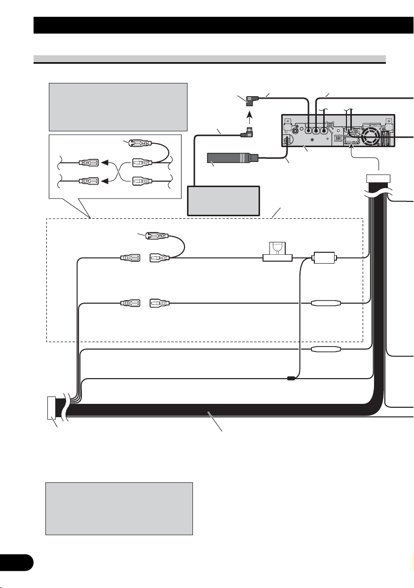
Connecting the Units
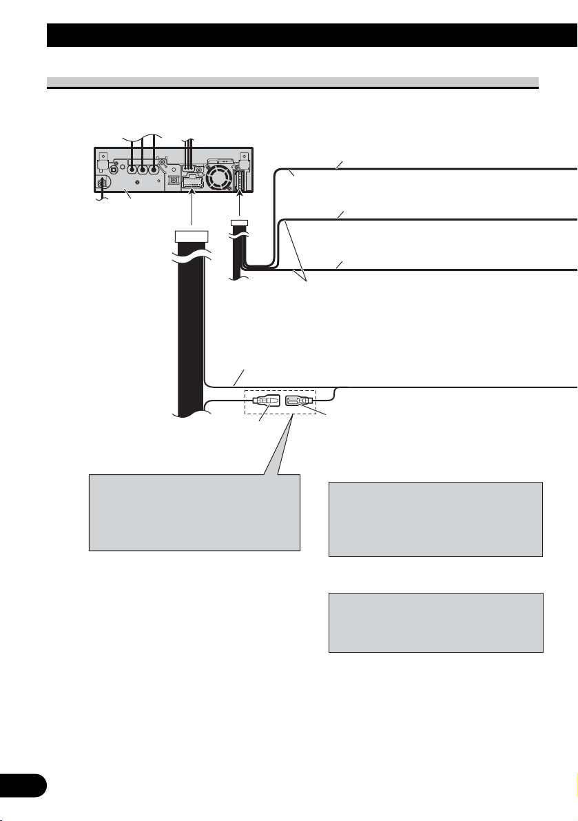
Connecting the power cord
14 cm
Speaker leads
White: Front left +
White/black: Front left ≠
Gray: Front right +
Gray/black: Front right ≠
Green: Rear left + or subwoofer +
Green/black: Rear left ≠ or subwoofer ≠
Violet: Rear right + or subwoofer +
Violet/black: Rear right ≠ or subwoofer ≠
ISO connector
Note:
In some vehicles, the ISO connector may be
divided into two. In this case, be sure to
connect to both connectors.
When you connect the separately sold multichannel processor (e.g., DEQ-P6600) to this
unit, do not connect anything to the speaker
leads and system remote control
(blue/white).
Note:
Depending on the kind of vehicle, the
function of 3* and 5* may be different.
In this case, be sure to connect 2* to 5*
and 4* to 3*.
1*
2*
4*
3*
5*
Cap (1*)
Do not remove cap if this
terminal is not in use.
Yellow (3*)
Back-up
(or accessory)
Yellow (2*)
Connect to the constant 12 V
supply terminal.
Connect leads of the same
color to each other.
Fuse (10 A)
Fuse resistor
Red (5*)
Accessory
(or back-up)
Red (4*)
Connect to terminal controlled by
ignition switch (12 V DC).
Black (chassis ground)
Connect to a clean, paint-free metal location.
Fuse resistor
Orange/white
Connect to lighting switch terminal.
IP-BUS input
(Blue)
IP-BUS cable
Multi-CD player
(sold separately)
15 cm
This product
15 cm
Antenna cable
Page 5
English
Español
Deutsch
Français
Italiano
Nederlands
PyТТНЛИ
4
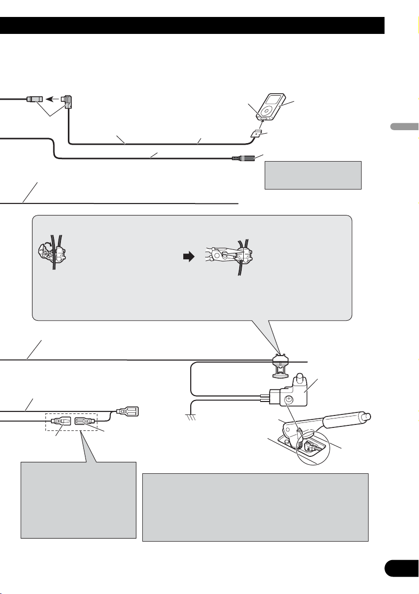
Notes:
• Change the initial setting of this unit (refer to the Operation
Manual). The subwoofer output of this unit is monaural.
• When using a subwoofer of 70 W (2 Ω) , be sure to connect with
Violet and Violet/black leads of this unit. Do not connect
anything to Green and Green/black leads.
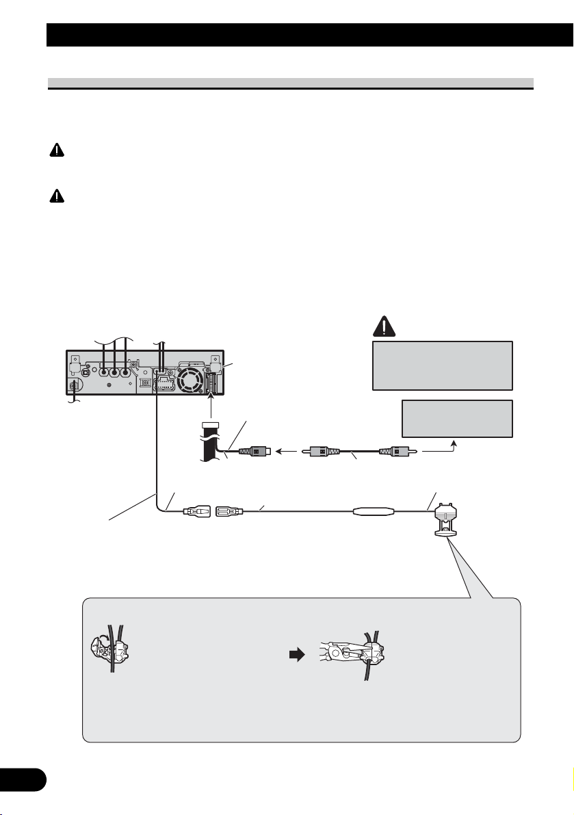
iPod with Dock
Connector
Dock connector
Interface cable (e.g., CD-I200)
(sold separately)
2 m
Connection method
1. Clamp the lead.
2. Clamp firmly with
needle-nosed pliers.
Note:
• The position of the parking brake switch depends on the vehicle model. For details,
consult the vehicle Owner’s Manual or dealer.
Yellow/black
If you use equipment with Mute function, wire this lead to
the Audio Mute lead on that piece of equipment. If not,
keep the Audio Mute lead free of any connections.
Light green
Used to detect the ON/OFF status of the parking brake. This
lead must be connected to the power supply side of the parking
brake switch.
Blue/white
Connect to system control terminal of the power
amp (max. 300 mA 12 V DC).
Blue/white (7*)
Connect to auto-antenna relay control terminal
(max. 300 mA 12 V DC).
The pin position of the ISO
connector will differ depending
on the type of vehicle. Connect
6* and 7* when Pin 5 is an
antenna control type. In other
types of vehicles, never connect
6* and 7*.
Blue/white (6*)
Ground side
Power supply side
Parking brake
switch
Dock connector port
Gray
AUX jack (3.5 ø)
20 cm
Use a mini plug cable to
connect with auxiliary
equipment.
Page 6
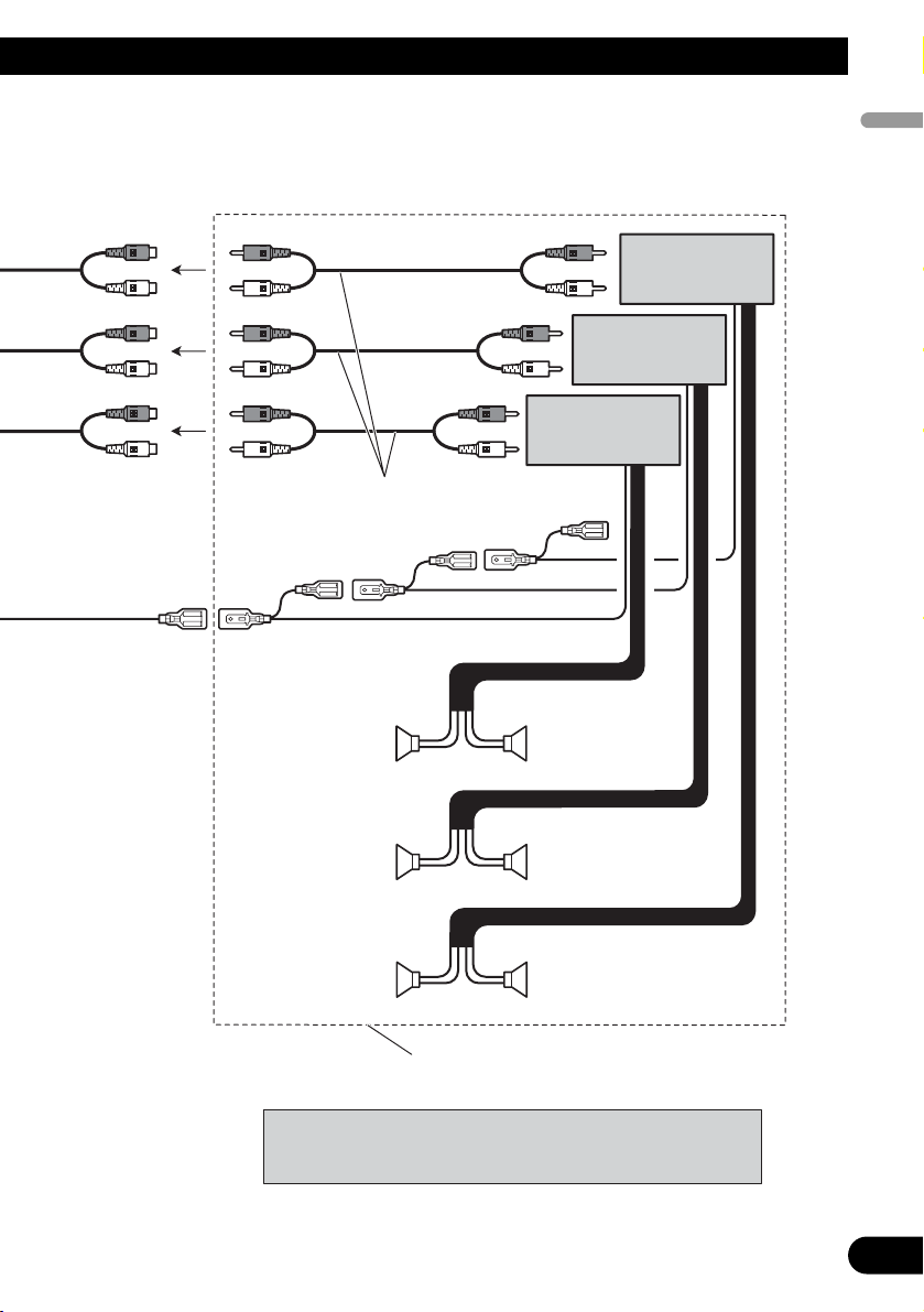
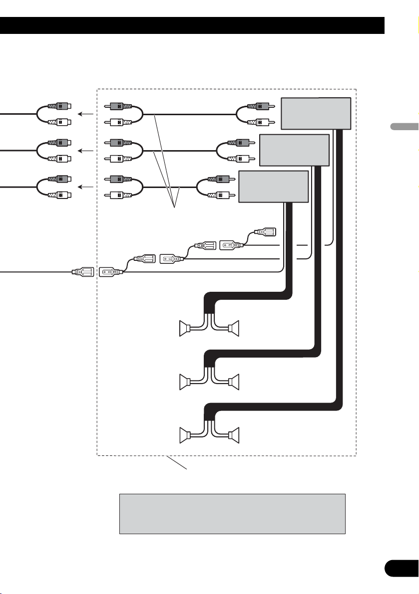
When connecting to separately sold power amp
5
Connecting the Units
Blue/white
Connect to system control terminal of the power
amp (max. 300 mA 12 V DC).
Blue/white (7*)
Connect to auto-antenna relay control terminal
(max. 300 mA 12 V DC).
The pin position of the ISO connector will
differ depending on the type of vehicle.
Connect 6* and 7* when Pin 5 is an antenna
control type. In other types of vehicles, never
connect 6* and 7*.
Blue/white (6*)
When you connect the separately sold multichannel processor (e.g., DEQ-P6600) to this
unit, do not connect anything to the speaker
leads and system remote control
(blue/white).
This product
Front output
(FRONT OUTPUT)
Rear output
(REAR OUTPUT)
Subwoofer output (SUBWOOFER
OUTPUT or DEQ OUTPUT)
When you connect the multi-channel
processor to this unit, refer to multi-channel
processor’s installation manual for the
connection method.
15 cm
20 cm
Page 7
English
Español
Deutsch
Français
Italiano
Nederlands
PyТТНЛИ
6
++
≠
≠
++
++
≠≠
≠
≠
Note:
• Change the initial setting of this unit (refer to the Operation
Manual). The subwoofer output of this unit is monaural.
Power amp
(sold separately)
Power amp
(sold separately)
Power amp
(sold separately)
Connect with RCA cables
(sold separately)
Subwoofer
Rear speaker
Perform these connections when
using the optional amplifier.
System remote control
Front speaker Front speaker
Left Right
Rear speaker
Subwoofer
Page 8
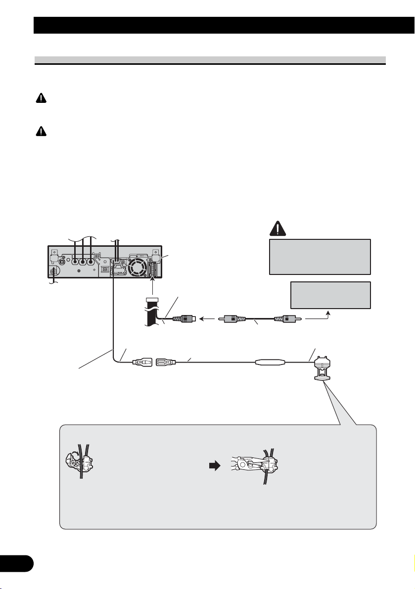
When connecting with a rear view camera
When using this product with a rear view camera, automatic switching to video from a
rear view camera when the gear shift is moved to REVERSE (R) position is possible.
WARNING
USE INPUT ONLY FOR REVERSE OR MIRROR IMAGE REAR VIEW CAMERA. OTHER USE MAY
RESULT IN INJURY OR DAMAGE.
CAUTION
•
The screen image may appear reversed.
• The rear view camera function is to be used as an aid for backing into a tight parking spot. Do not use this
function for entertainment purposes.
• Objects in the rear view may appear closer or more distant than they actually are.
7
Connecting the Units
CAUTION
This product
Rear view camera input
(REAR VIEW
CAMERA IN)
20 cm
10 cm
Extension lead (supplied)
Violet/white
Of the two lead wires connected to the back lamp, connect the
one in which the voltage changes when the gear shift is in the
REVERSE (R) position. This connection enables the unit to
sense whether the car is moving forwards or backwards.
Connection method
1. Clamp the lead.
Note:
• It is necessary to set CAMERA POLARITY properly in SYSTEM MENU when
connecting the rear view camera.
RCA cable
(sold separately)
You must use a camera
which outputs mirror
reversed images.
Rear view camera
Fuse resistor
2. Clamp firmly with
needle-nosed pliers.
To video output
8 m
Page 9
English
Español
Deutsch
Français
Italiano
Nederlands
PyТТНЛИ
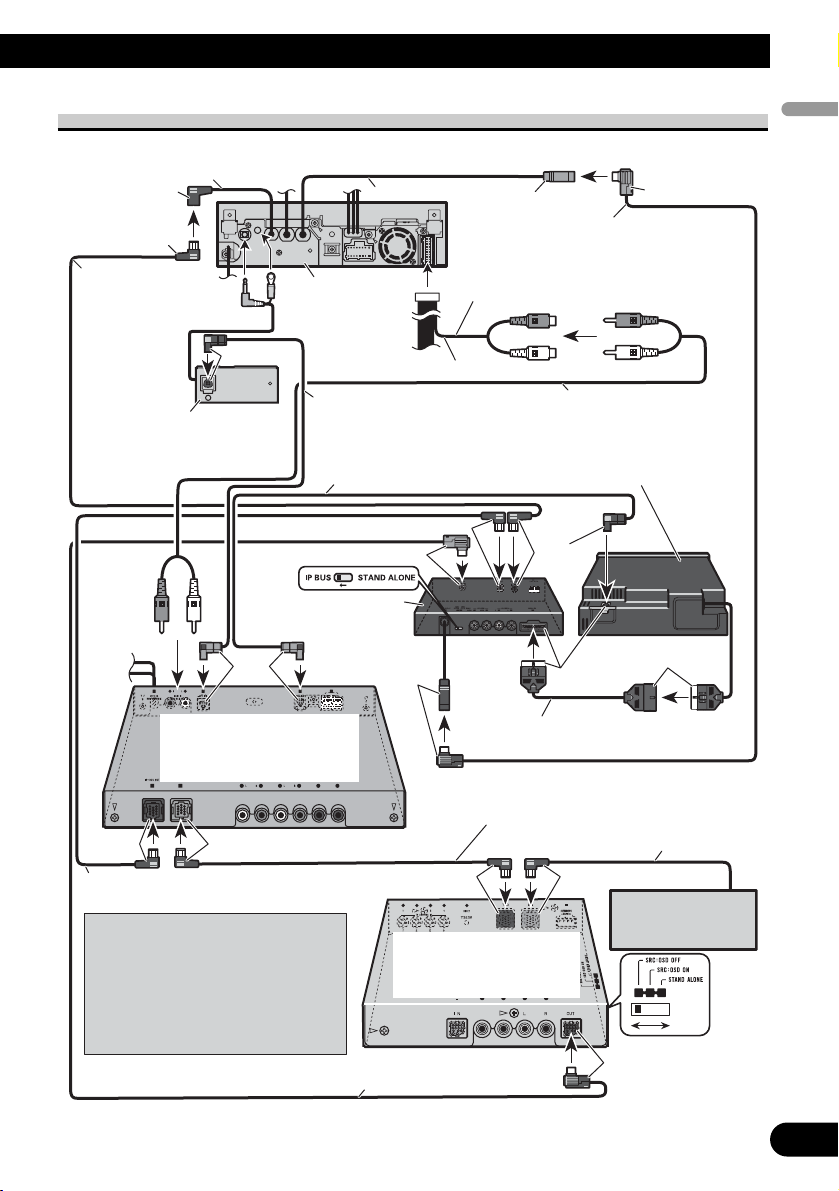
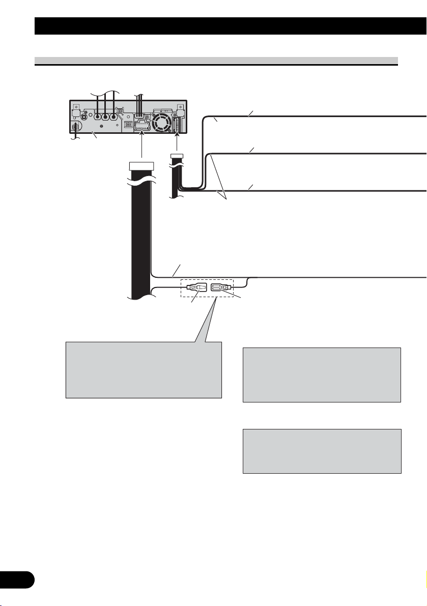
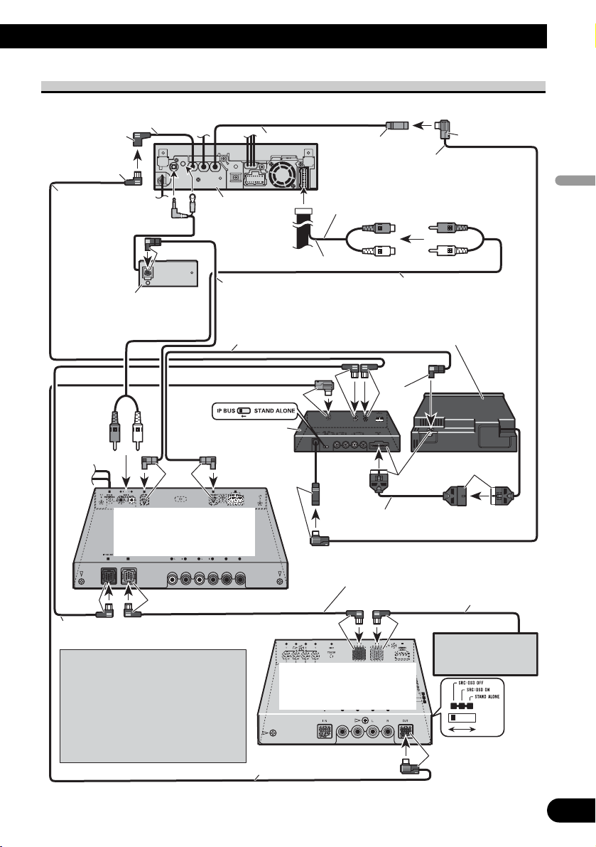
When connecting with a multi-channel processor
8
IP-BUS input
15 cm
(Blue)
Blue
IP-BUS cable
(supplied with DVD
player)
Black
Optical cable connection box
(supplied with multi-channel
processor)
Blue
Multi-channel processor
(e.g., DEQ-P6600)
(sold separately)
Black Blue
44 cm
This product
Optical cable (supplied with
multi-channel processor)
Optical cable (sold
separately)
Hide-away unit (supplied
with DVD player)
Black
AV-BUS input
(Blue)
DEQ output (SUBWOOFER
OUTPUT or DEQ OUTPUT)
20 cm
Blue
Blue
IP-BUS cable (supplied
with TV tuner)
AV-BUS cable (supplied
with DVD player)
RCA cable (supplied with
multi-channel processor)
DVD player (e.g., XDV-P6)
(sold separately)
Black
Black
25 pin cable (supplied
with DVD player)
IP-BUS cable
Blue
Black
IP-BUS cable (supplied with
multi-channel processor)
When you connect a separately sold
DVD player to the separetely sold
multi-channel processor, the optical
cable from DVD player must be
connected to the optical cable 2 input
(OPT. IN2) of the multi-channel
processor.
Black Blue
Hide-away TV tuner
(e.g., GEX-P5700TVP)
(sold separately)
AV-BUS cable (supplied
with TV tuner)
Multi-CD player
(sold separately)
Black
Page 10
9
Connecting the Units
Connecting and installing the
optical cable connection box
WARNING
• Avoid installing this unit in locations where the
operation of safety devices such as airbags is prevented by this unit. Otherwise, there is a danger of
a fatal accident.
• Avoid installing this unit in locations where the
operation of the brake may be prevented.
Otherwise, it may result in a traffic accident.
• Fix this unit securely with the velcro tape or lock
tie. If this unit is loose, it disturbs driving stability, which may result in a traffic accident.
CAUTION
• Install this unit using only the parts supplied with
this unit. If other parts are used, this unit may be
damaged or could dismount itself, which leads to
an accident or other problems.
• Do not install this unit near the doors where rainwater is likely to be spilled on the unit. Incursion
of water into the unit may cause smoke or fire.
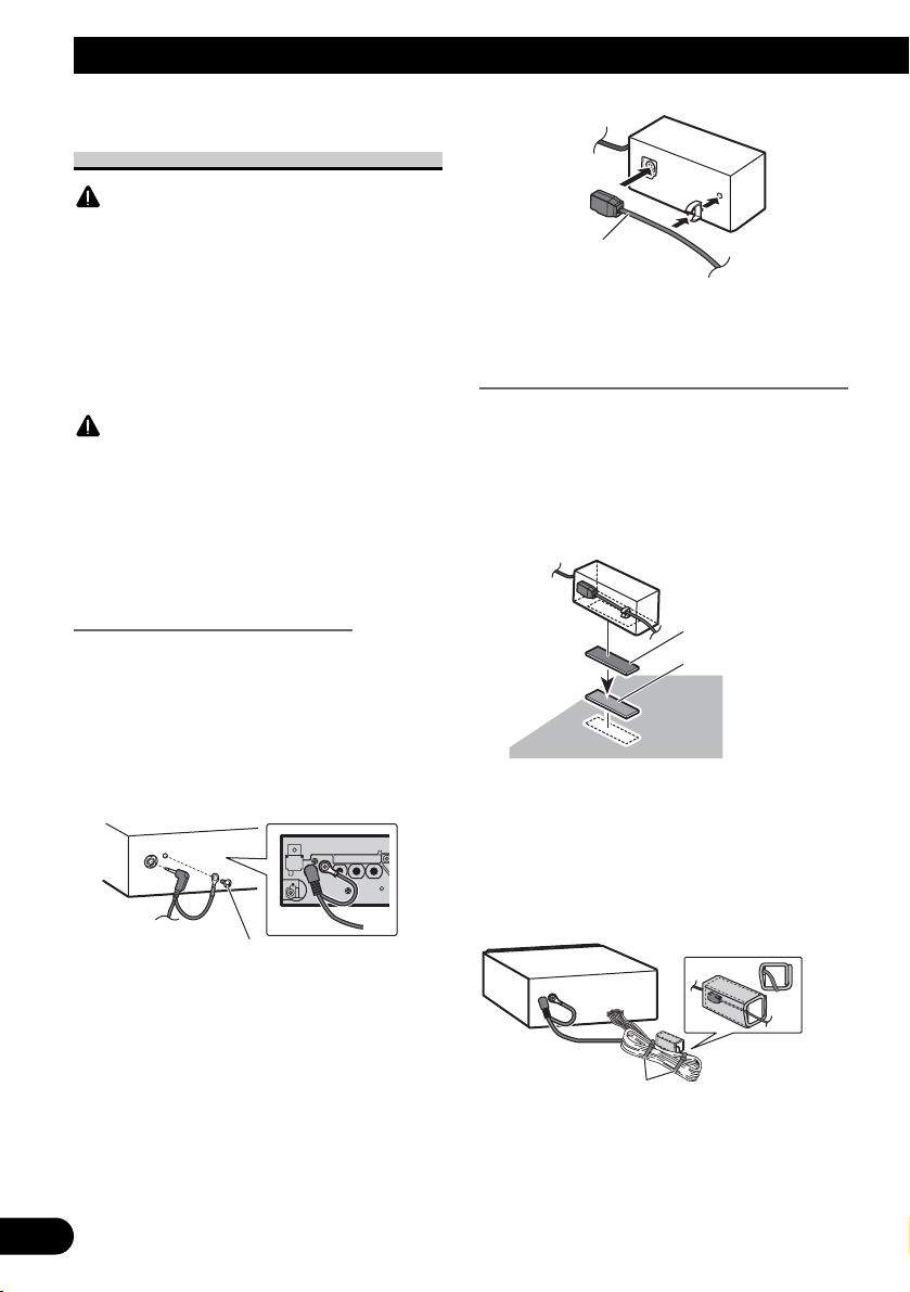
Connecting the optical cable
1. Connect the optical cable and
ground lead to the main unit.
Connect the optical cable so that it
does not protrude from the unit, as
shown in the illustration. Fasten the
ground lead to the protrusion on the
back of the unit.
2.
Connect the optical cable to the
optical cable connection box.
Installing the optical cable
connection box
• When
installing the optical cable
connection box with the velcro
tape.
Install the optical cable connection box
using the velcro tape in the ample
space of the console box.
• When installing the optical cable
connection box with the lock tie.
Wrap the optical cable and connection
box with the protection tape and fasten
with the power code using the lock tie.
Optical cable
Screw
Velcro tape (hard)
Velcro tape (soft)
Wrap with the protection tape
Fasten with the lock tie
Page 11
English
Español
Deutsch
Français
Italiano
Nederlands
PyТТНЛИ
10
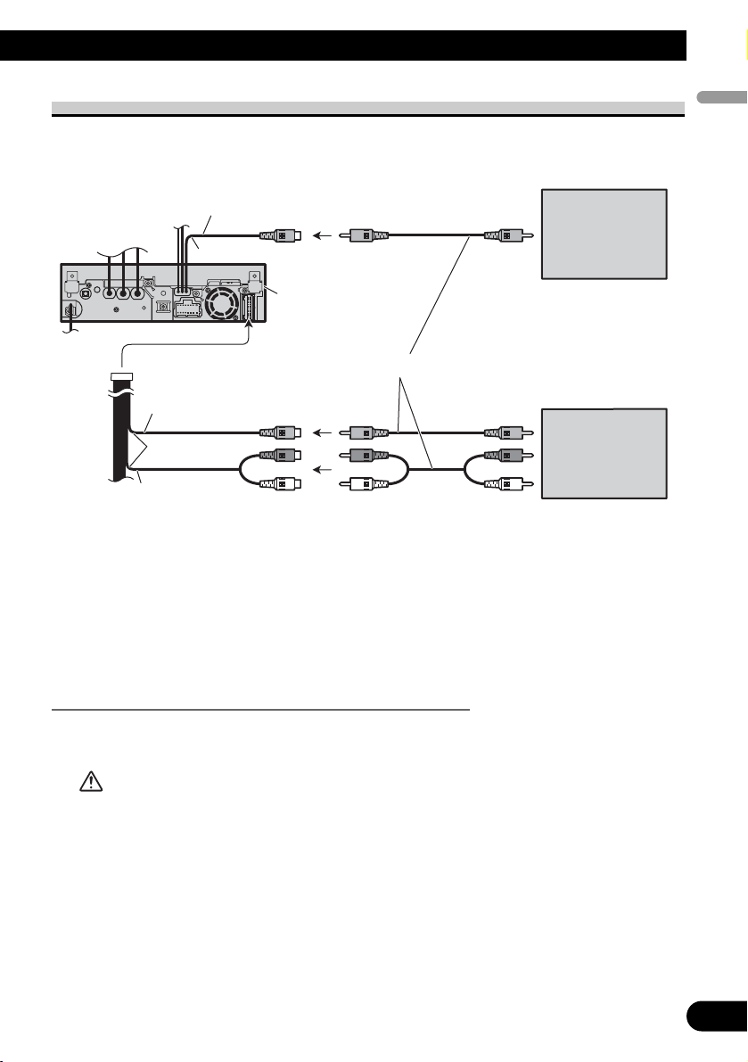
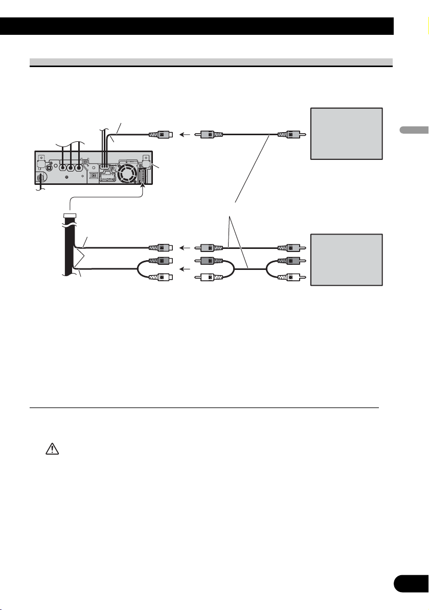
When connecting the external video component and the display
• It is necessary to set AV INPUT to VIDEO in SYSTEM MENU when connecting the
external video component.
• It is necessary to set AV INPUT to S-DVD in SYSTEM MENU when connecting a
multi-DVD player.
When using a display connected to rear video output
This product’s rear video output is for connection of a display to enable passengers in the
rear seats to watch the DVD or Video CD.
WARNING
• NEVER install the display in a location that enables the Driver to watch the DVD or Video CD
while driving.
Rear monitor output
(REAR MONITOR OUTPUT)
15 cm
This product
To video input
Display with
RCA input jacks
(sold separately)
RCA cables (sold separately)
Video input
(VIDEO INPUT)
25 cm
Audio input
(AUDIO INPUT)
To video output
External video
component
(sold separately)
To audio outputs
Page 12
11
Note:
• Check all connections and systems before final
installation.
• Do not use unauthorized parts. The use of
unauthorized parts may cause malfunctions.
• Consult with your dealer if installation requires
drilling of holes or other modifications of the
vehicle.
• Do not install this unit where:
— it may interfere with operation of the vehicle.
— it may cause injury to a passenger as a result
of a sudden stop.
• Do not install the display where it may (i)
obstruct the driver’s vision, (ii) impair the performance of any of the vehicle’s operating systems or safety features, including air bags, hazard lamp buttons or (iii) impair the driver’s ability to safely operate the vehicle.
• The semiconductor laser will be damaged if it
overheats. Install this unit away from hot places
such as near the heater outlet.
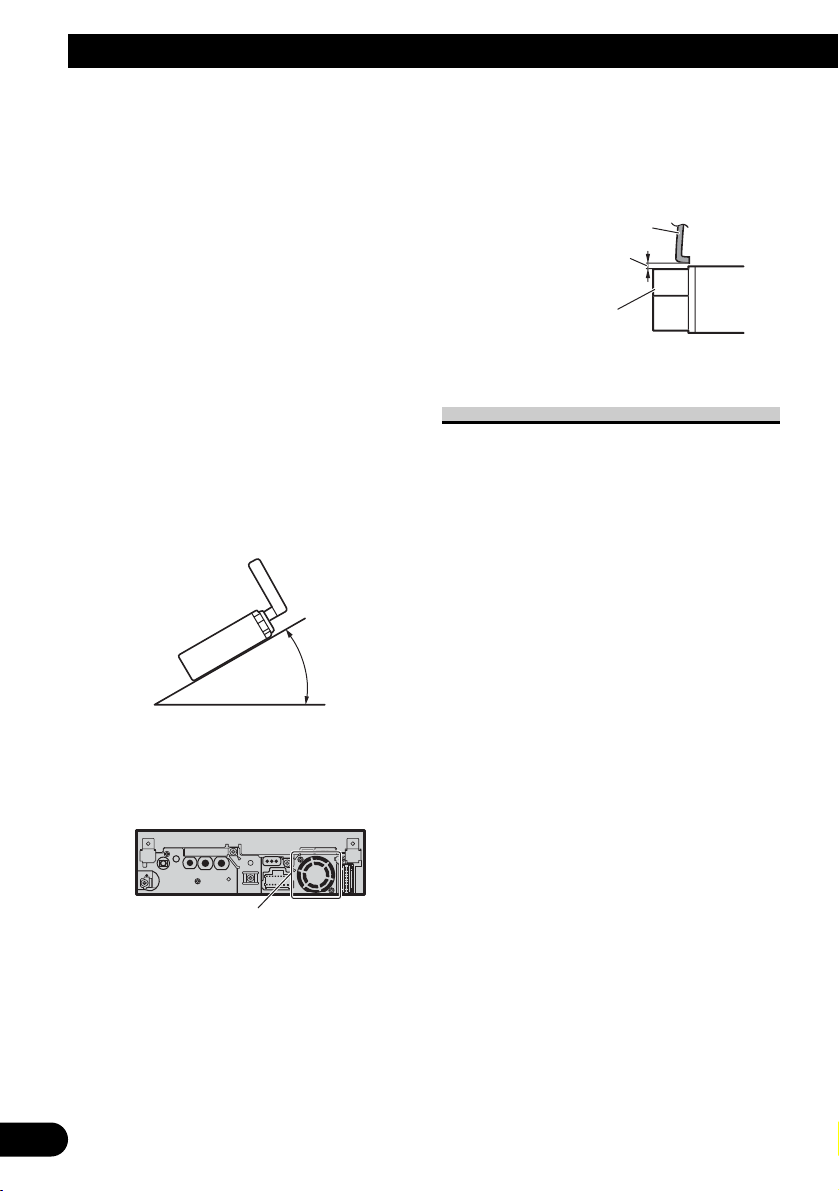
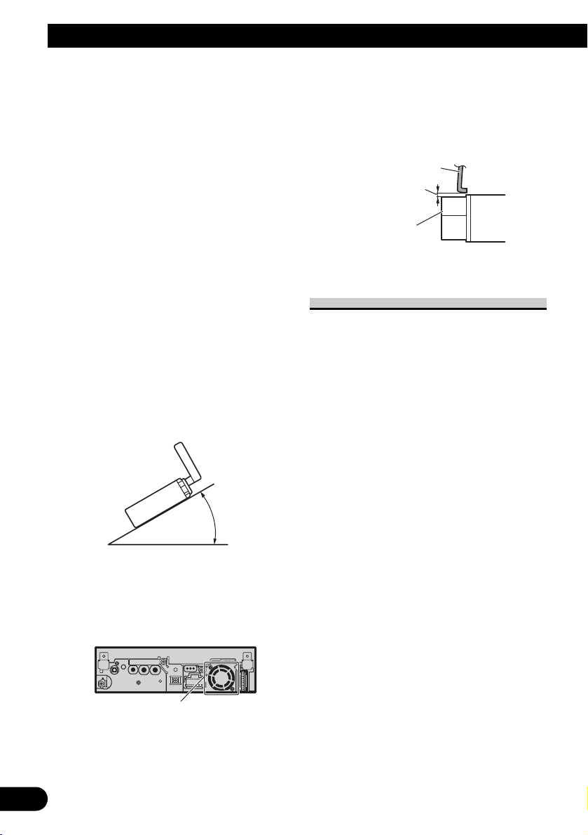
• Optimum performance is obtained when the unit
is installed at an angle of less than 30°.
• The cords must not cover up the area shown in
the figure below. This is necessary to allow the
amplifires to radiate freely.
• Make sure you leave enough gap between the
dashboard and the LCD panel of this unit so the
LCD panel can be opened and closed without
contacting with the dashboard.
DIN Front/Rear-mount
This unit can be properly installed
either from “Front” (conventional DIN
Front-mount) or “Rear” (DIN Rearmount installation, utilizing threaded
screw holes at the sides of unit chassis). For details, refer to the following
illustrated installation methods.
Dashb
d
p
l
Installation
30°
oar
Leave ga
LCD pane
Do not cover this area.
Page 13
English
Español
Deutsch
Français
Italiano
Nederlands
PyТТНЛИ
12
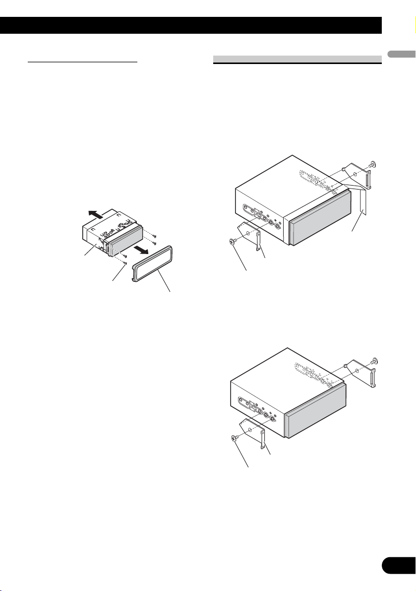
Before installing the unit
• Remove the trim ring and the
mounting sleeve.
Extend top and bottom of the trim ring
outwards to remove the trim ring. And
then loosen the screws (2 mm × 3 mm)
to remove the mounting sleeve.
• When reattaching the trim ring, push
the trim ring onto the unit until it
clicks after reattaching the mounting
sleeve. (If the trim ring is attached
upside down, the trim ring will not
fit properly.)
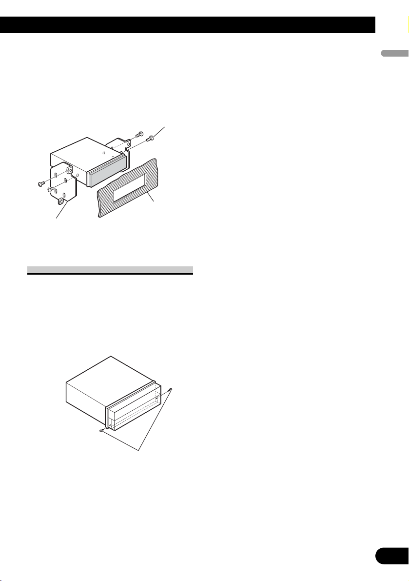
DIN Front-mount
1. Decide the position of the side
brackets.
• When installing in a shallow space,
change the position of side brackets
(small). In this case, stick concealing
tape on parts that protrude from the
dashboard.
• If you prefer an off-set installation
in which the front panel is pushed
further back, when there is a space
available at the back of the unit, use
the side brackets (large).
)
)
M
e
g
)
Concealing tape
ounting sleev
Screw (2 mm
3 mm
Trim rin
Side bracket (small)
Flush surface screw (5 mm × 6 mm)
Side bracket (large
Flush surface screw (5 mm
6 mm
Page 14
13
Installation
2. Install the unit into the dashboard.
Insert the mounting sleeve into the
dashboard. And then secure the mounting sleeve by using a screwdriver to
bend the metal tabs (90°) into place.
DIN Rear-mount
1. Determine the appropriate position where the holes on the
bracket and the side of the unit
match.
*1 Use binding screws (4 mm × 3 mm) only.
• When installing in a shallow space,
use the following screw holes. In
this case, stick concealing tape on
parts that protrude from the dashboard.
Dashboard
182
53
Mounting sleeve
Side bracket
Screw (2 mm × 3 mm)
Rubber bush
Screw
*
*
*1
*1
Concealing tape
Page 15
English
Español
Deutsch
Français
Italiano
Nederlands
PyТТНЛИ
14
2. Tighten two screws on each side.
Use any of binding screws (4 mm × 3
mm), binding screws (5 mm × 6 mm)
or flush surface screws (5 mm × 6
mm), depending on the shape of screw
holes in the bracket.
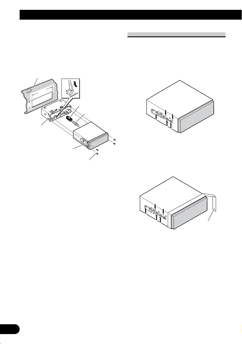
Fastening the front panel
If you do not plan to detach the front
panel, the front panel can be fastened
with supplied screws.
• Fix the front panel to the unit
using screws after removing the
trim ring.
S
ws
Screw
Dashboard or
Console
Factory radio mounting
bracket
cre
Page 16
1
Contenido
Conexión de las unidades ........................ 1
Conexión del cable de alimentación .................. 3
Cuando conecte a un amplificador de
potencia vendido separadamente ................ 5
Cuando conecte con una cámara de
vista trasera ................................................ 7
Cuando conecte con un procesador
multicanal .................................................. 8
Conexión e instalación de la caja de conexión
de cable óptico ............................................ 9
Cuando conecte el componente externo y
la pantalla ................................................ 10
Instalación ................................................ 11
Montaje delantero/trasero DIN ........................ 11
Montaje delantero DIN .................................... 12
Montaje trasero DIN ........................................ 13
Fijación del panel delantero ............................ 14
ADVERTENCIA
• Para evitar el riesgo de accidentes e violación
potencial de las leyes aplicables, no se debe usar
nunca la función de DVD o TV frontal (vendido
separadamente) mientras el vehículo esté siendo
conducido. Igualmente, los monitores traseros no
deben quedarse en un sitio donde puedan causar
una distracción visible al conductor.
• En algunos países o estados, puede ser ilícita la
visualización de imágenes en un display dentro de
un vehículo, incluso por otras personas que no
sean el conductor. En los casos en que resulten
aplicables, estas normas deben respetarse y no
deben usarse las funciones de DVD de esta
unidad.
PRECAUCIÓN
• PIONEER no recomienda que sea usted
mismo quien instale o revise su pantalla.
La instalación o revisión del producto
puede exponerle a descargas eléctricas u
otros peligros. Solicite que todos los
trabajos de instalación y revisión de su
pantalla los realice el personal de
servicio Pioneer autorizado.
• Asegure todo el cableado con
abrazaderas de cables o cinta para usos
eléctricos. No permita que el cableado
pelado permanezca expuesto.
• No taladre un agujero en el
compartimiento del motor para
conectar el cable amarillo de la unidad a
la batería del vehículo. La vibración del
motor podría estropear el aislamiento
en el punto por donde el cable pasa del
compartimiento de los pasajeros al
compartimiento del motor. Tenga
mucho cuidado para mantener el buen
estado del cable en lo relativo a este
punto.
• Es peligrosísimo dejar que el cable de la
pantalla se enrolle en la base del volante
o en la palanca de cambios. Asegúrese
de instalar la pantalla de forma que ésta
no sea un obstáculo para la conducción.
• Asegúrese de que los cables no
interfieran con partes móviles del
vehículo tales como la palanca de
cambio, el freno de mano o el
mecanismo de deslizamiento de los
asientos.
• No acorte ningún cable. Si lo hace, el
circuito de protección tal vez no
funcione correctamente.
ADVERTENCIA
EL CABLE VERDE CLARO DEL CONECTOR
DE ALIMENTACIÓN ESTÁ DISEÑADO PARA
DETECTAR SI EL VEHÍCULO ESTÁ
ESTACIONADO Y DEBE CONECTARSE CON
EL LADO DE LA FUENTE DE ALIMENTACIÓN
DEL INTERRUPTOR DEL FRENO DE MANO.
LA CONEXIÓN O EL USO INCORRECTO DE
ESTE CABLE PUEDE INFRINGIR LAS LEYES
PERTINENTES Y OCASIONAR LESIONES
FÍSICAS O DAÑOS GRAVES.
Conexión de las unidades
Page 17
English
Español
Deutsch
Français
Italiano
Nederlands
PyТТНЛИ
2
Nota:
• No se puede instalar esta unidad en un vehículo sin una posición ACC (accesorio) en el
interruptor de encendido.
• El uso de esta unidad en condiciones diferentes
de las siguientes podría causar un fuego o fallo
de funcionamiento.
— Vehículos con una batería de 12 voltios y
puesta a tierra negativa.
— Altavoz con 50 W (valor de salida) y de 4 a 8
ohmios (valor de impedancia).
• Para prevenir cortocircuitos, sobrecalentamiento
o fallo de funcionamiento, asegúrese de seguir
las instrucciones a continuación.
— Desenchufe el terminal negativo de la batería
antes de la instalación.
— Fije el cableado con abrazaderas de cable o
con cinta adhesiva. Para proteger el cableado,
envuélvalo con cinta adhesiva donde el
cableado se apoya sobre piezas metálicas.
— Posicione todos los cables alejados de las
piezas móviles, como el cambio de marchas y
rieles de los asientos.
— Posicione todos los cables alejados de lugares
calientes como cerca de la salida del calentador.
— No pase el cable amarillo a través de un agu-
jero en el compartimiento del motor para
conectar la batería.
— Cubra cualquier conector de cable desconec-
tado con cinta de aislamiento.
— No extraiga las tapas RCA si no se utilizan
los cables RCA.
— No acorte ningún cable.
— No corte nunca el aislamiento del cable de
alimentación de esta unidad para compartir la
energía con otro equipo. La capacidad de cor-
riente del cable es limitada.
— Utilice un fusible con la capacidad especifi-
cada.
— No conecte nunca el cable negativo de
altavoz directamente a la puesta a tierra.
— No junte nunca múltiples cables negativos de
altavoz.
• La señal de control se emite a través del cable
azul/blanco cuando se enciende esta unidad.
Conéctelo a un terminal de control de sistema de
amplificador de potencia externo o al terminal de
control de relé de antena automática del vehículo
(máx. 300 mA, 12 V CC). Si el vehículo está
equipado con una antena de vidrio, conéctelo al
terminal de suministro de potencia de refuerzo de
la antena.
• No conecte nunca el cable azul/blanco al terminal de alimentación de un amplificador de potencia externo. Igualmente, no conéctelo nunca al
terminal de alimentación de la antena automática. De lo contrario, puede ocurrir la descarga de
la batería o un fallo de funcionamiento.
• Los conectores IP-BUS están codificados en
colores. Asegúrese de conectar los conectores
del mismo color.
• El cable negro es para la puesta a tierra. Se debe
conectar este cable y el cable de puesta a tierra
de otro producto (especialmente de productos de
alta corriente como un amplificador de potencia)
separadamente. De lo contrario, puede ocurrir un
fuego o fallo de funcionamiento si los cables se
sueltan accidentalmente.
• La función del cable puede diferir de acuerdo
con el producto, aunque el color del cable sea
igual. Cuando conecte este sistema, asegúrese
de verificar todos los manuales y conecte los
cables correctamente.
Sin posición ACCPosición ACC
C
C
A
O
F
N
F
O
S
T
A
R
T
O
F
N
F
O
S
T
A
R
T
Page 18
3
Conexión de las unidades
Conexión del cable de alimentación
14 cm
Conector ISO
Nota:
En algunos vehículos, puede que el conector
ISO esté dividido en dos. En este caso,
asegúrese de conectar a ambos conectores.
Nota:
Dependiendo del tipo de vehículo, la
función de 3* y 5* puede ser diferente.
En este caso, asegúrese de conectar 2*
a 5* y 4* a 3*.
1*
2*
4*
3*
5*
Tapa (1*)
No quite la tapa cuando no
se utiliza este terminal.
Amarillo (3*)
Reserva
(o accesorio)
Amarillo (2*)
Conecte el terminal de
suministro de 12 V constante.
Conecte los hilos del
mismo color a cada otro.
Fusible (10 A)
Rojo (5*)
Accesorio
(o reserva)
Rojo (4*)
Conecte al terminal controlado por del
interruptor de encendido (12 V CC).
Negro (masa de la carrocería)
Conecte a un punto de metal limpio, libre de pintura.
Anaranjado/blanco
Conecte al terminal de interruptor de iluminación.
Entrada IP-BUS
(Azul)
Cable IP-BUS
Reproductor de
Multi-CD (vendido
separadamente)
15 cm
Este producto
15 cm
Cable de antena
Resistencia
de fusible
Resistencia
de fusible
Cuando conecte el procesador multicanal
(e.g., DEQ-P6600) vendido separadamente
a esta unidad, no conecte nada a los
conductores de los altavoces y al control
remoto del sistema (azul/blanco).
Hilos de altavoz
Blanco: Izquierda delantera +
Blanco/negro
: Izquierda delantera ≠
Gris: Derecha delantera +
Gris/negro: Derecha delantera ≠
Verde: Izquierda trasera + o altavoz de subgraves +
Verde/negro: Izquierda trasera ≠ o altavoz de subgraves ≠
Violeta: Derecha trasera + o altavoz de subgraves +
Violeta/negro
: Derecha trasera ≠ o altavoz de subgraves ≠
Page 19
English
Español
Deutsch
Français
Italiano
Nederlands
PyТТНЛИ
4
Notas:
• Cambie el ajuste inicial de esta unidad (refiérase al manual de
operación). La salida de altavoz de subgraves de esta unidad es
monofónica.
• Cuando utilice un altavoz de subgraves de 70 W (2 Ω), asegúrese
de conectarlo con los hilos Violeta y Violeta/negro de esta
unidad. No conecte nada a los hilos Verde y Verde/negro.
iPod con conector
del Dock
Conector del Dock
Cable de interfaz (e.g., CD-I200)
(vendido separadamente)
2 m
Amarillo/negro
Si se utiliza un equipo con función de silenciamiento, conecte
este conductor con el conductor de silenciamiento de audio en
tal parte del equipo. De lo contrario, mantenga el conductor de
silenciamiento de audio libre de conexiones.
Azul/blanco
Conecte al terminal de control de sistema del
amplificador de potencia (máx. 300 mA 12 V CC).
Azul/blanco (7*)
Conecte al terminal de control de relé de
antena automática (máx. 300 mA 12 V CC).
La posición de los contactos del
conector ISO difiere
dependiendo del tipo del
vehículo. Conecte 6* y 7*
cuando el contacto 5 es del tipo
de control de antena. En otros
tipos de vehículo, no conecte
nunca 6* y 7*.
Azul/blanco (6*)
Puerto del conector del Dock
Gris
Toma AUX (3,5 ø)
20 cm
Utilice un cable con enchufe
miniatura para conectar a un
equipo auxiliar.
Interruptor
del freno de
mano
Lado de alimentación
Lado de masa
Verde claro
Se utiliza para detectar el estado ON/OFF del freno de
mano. Este cable debe conectarse al lado de alimentación
del interruptor del freno de mano.
Método de conexión
Apriete el cable.1.
2.
Apriete firmemente
con alicates de
punta de aguja.
Nota:
• La posición del freno de estacionamiento depende
del modelo del vehículo. Para conocer detalles, consulte
el manual del propietario del vehículo o a su concesionario.
Page 20
Cuando conecte a un amplificador de potencia vendido separadamente
5
Conexión de las unidades
Azul/blanco
Conecte al terminal de control de sistema del
amplificador de potencia (máx. 300 mA 12 V CC).
Azul/blanco (7*)
Conecte al terminal de control de relé de
antena automática (máx. 300 mA 12 V CC).
La posición de los contactos del conector
ISO difiere dependiendo del tipo del
vehículo. Conecte 6* y 7* cuando el contacto
5 es del tipo de control de antena. En otros
tipos de vehículo, no conecte nunca 6* y 7*.
Azul/blanco (6*)
Este producto
Salida delantera
(FRONT OUTPUT)
Salida trasera
(REAR OUTPUT)
Salida de altavoz de subgraves
(SUBWOOFER OUTPUT or DEQ OUTPUT)
Cuando conecte el procesador multicanal a
esta unidad, consulte el manual de
instalación del procesador multicanal para
el método de conexión.
15 cm
20 cm
Cuando conecte el procesador multicanal
(e.g., DEQ-P6600) vendido separadamente a
esta unidad, no conecte nada a los
conductores de los altavoces y al control
remoto del sistema (azul/blanco).
Page 21
English
Español
Deutsch
Français
Italiano
Nederlands
PyТТНЛИ
6
++
≠
≠
++
++
≠≠
≠
≠
Nota:
• Cambie el ajuste inicial de esta unidad (refiérase al manual de
operación). La salida de altavoz de subgraves de esta unidad es
monofónica.
Amplificador de
potencia (vendido
separadamente)
Amplificador de
potencia (vendido
separadamente)
Amplificador de
potencia (vendido
separadamente)
Conecte los cables RCA
(vendidos separadamente)
Altavoz de subgraves
Altavoz trasero
Realice estas conexiones cuando
utilice el amplificador opcional.
Control remoto de sistema
Altavoz delantero Altavoz delantero
Izquierda Derecha
Altavoz trasero
Altavoz de subgraves
Page 22
Cuando conecte con una cámara de vista trasera
Cuando utilice este producto con una cámara de vista trasera, se puede realizar la conmutación automática a vídeo desde una cámara de vista trasera cuando se desplaza la
palanca de cambio de marchas a REVERSE (R).
ADVERTENCIA
UTILICE SOLAMENTE PARA CÁMARA DE VISTA TRASERA DE IMAGEN INVERTIDA O DE
ESPEJO. CUALQUIER OTRO USO PUEDE CAUSAR LESIONES O DAÑOS.
PRECAUCIÓN
•
La imagen de la pantalla puede aparecer invertida.
• Se debe utilizar la función de cámara de vista trasera como un auxilio para estacionar en lugares estrechos.
No utilice esta función para propósitos de entretenimiento.
• Los objetos en la vista trasera pueden parecer más cercanos o más distantes de que realmente están.
7
Conexión de las unidades
PRECAUCIÓN
Este producto
Entrada para cámara de
vista trasera (REAR
VIEW CAMERA IN)
Se debe utilizar una cámara
que genere imágenes
invertidas de espejo.
Cámara de vista trasera
20 cm
10 cm
Violeta/blanco
De los dos conductores conectados a la lámpara trasera, conecte el
conductor cuyo voltaje cambia cuando se desplaza la palanca de cambio
de marcha a la posición REVERSE (R). Esta conexión permite que la
unidad detecte si el vehículo está se moviendo hacia delante o hacia atrás.
Método de conexión
1. 2.
Apriete el cable.
Nota:
• Se requiere ajustar CAMERA POLARITY adecuadamente en el menú SYSTEM
MENU cuando conecte la cámara de vista trasera.
Cable de extensión (suministrado)
Cable RCA (vendido
separadamente)
Resistencia de fusible
A la salida de vídeo
8 m
Apriete firmemente
con alicates de
punta de aguja.
Page 23
English
Español
Deutsch
Français
Italiano
Nederlands
PyТТНЛИ
Cuando conecte con un procesador multicanal
8
Entrada IP-BUS
15 cm
(Azul)
Azul
Cable IP-BUS
(suministrado con el
reproductor de DVD)
Caja de conexión de cable
óptico (suministrada con el
procesador multicanal)
Procesador multicanal
(e.g., DEQ-P6600)
(vendido separadamente)
Negro Azul
Este producto
Negro
Unidad oculta-alejada
(suministrada con el
reproductor de DVD)
Azul
44 cm
Cable óptico (suministrado
con el procesador multicanal)
Cable óptico
(vendido separadamente)
Azul
Negro
Entrada
AV-BUS (Azul)
Salida DEQ (SUBWOOFER
OUTPUT or DEQ OUTPUT)
20 cm
Azul
Cable IP-BUS (suministrado con
el sintonizador de TV)
Azul
Cable AV-BUS
(suministrado con el
reproductor de DVD)
Cable RCA (suministrado
con el procesador
multicanal)
Reproductor de DVD (e.g., XDV-P6)
(vendido separadamente)
Negro
Negro
Negro
Cable de 25 contactos (suministrado
con el reproductor de DVD)
Cable IP-BUS
Cable IP-BUS (suministrado
con el procesador multicanal)
Cuando conecte un reproductor de
DVD vendido separadamente al
procesador de canales múltiples
vendido separadamente, se debe
conectar el cable óptico del reproductor
de DVD a la entrada de cable óptico 2
(OPT. IN2) del procesador de canales
múltiples.
Negro Azul
Sintonizador TV ocultolejos (e.g., GEX-P5700TVP)
(vendido separadamente)
Cable AV-BUS (suministrado
con el sintonizador de TV)
Reproductor de
Multi-CD (vendido
separadamente)
Negro
Page 24
9
Conexión de las unidades
Conexión e instalación de la caja
de conexión de cable óptico
ADVERTENCIA
• Evite instalar esta unidad en lugares donde la
misma pueda obstruir la operación de los dispositivos de seguridad como el airbag. De lo contrario, hay el peligro de un accidente fatal.
• Evite instalar esta unidad en lugares donde la
misma pueda obstruir la operación del freno. De
lo contrario, esto podría causar un accidente de
tráfico.
• Fije esta unidad firmemente con la cinta Velcro o
atadura de fijación. Si esta unidad está floja,
puede estorbar la estabilidad de conducción, lo
que podría causar un accidente de tráfico.
PRECAUCIÓN
• Instale esta unidad utilizando solamente las piezas
suministradas con la misma. Si se utilizan otras
piezas, la unidad podría dañarse o desmontarse, lo
que causaría un accidente u otros problemas.
• No instale esta unidad cerca de las puertas donde
el agua de la lluvia podría derramar sobre la
unidad. La penetración de agua en la unidad
puede causar el humo o fuego.
Conexión del cable óptico
1. Conecte el cable óptico y hilo de
tierra a la unidad principal.
Conecte el cable óptico de manera que
no se sobresalga de la unidad, como se
muestra en la ilustración. Apriete el
hilo de tierra a la protuberancia en la
parte posterior de la unidad.
2.
Conecte el cable óptico a la caja
de conexión de cable óptico.
Instalación de la caja de conexión
de cable óptico
• Cuando instale la caja de
conexión de cable óptico con la
cinta Velcro.
Instale la caja de conexión de cable
óptico usando la cinta Velcro en el
espacio ancho de la caja de la consola.
• Cuando instale la caja de
conexión de cable óptico con la
atadura de fijación.
Envuelva el cable óptico y la caja de
conexión con la cinta protectora y apriete con el cable de alimentación usando la atadura de fijación.
Tornillo
Cable óptico
Cinta Velcro (dura)
Cinta Velcro (blanda)
Envuelva con la
cinta protectora
Apriete con la atadura de fijación
Page 25
English
Español
Deutsch
Français
Italiano
Nederlands
PyТТНЛИ
10
Cuando conecte el componente externo y la pantalla
• Se requiere ajustar AV INPUT a VIDEO en SYSTEM MENU cuando conecte el com-
ponente de vídeo externo.
• Se requiere ajustar AV INPUT a S-DVD en SYSTEM MENU cuando conecte un
reproductor de multi-DVD.
Cuando utilice un presentación visual conectado a la salida de vídeo trasera
La salida de vídeo trasera de este producto es para la conexión de un presentación visual
para permitir que los pasajeros en los asientos traseros puedan ver el DVD o Video CD.
ADVERTENCIA
• NUNCA instale el presentación visual en un lugar que permita el motorista ver el DVD o Video
CD mientras conduce el automóvil.
Salida de monitor posterior
(REAR MONITOR OUTPUT)
15 cm
Este producto
A la entrada de vídeo
Pantalla con tomas
de entrada RCA
(vendida
separadamente)
Cable RCA (vendido separadamente)
Entrada de vídeo
(VIDEO INPUT)
25 cm
Entrada de audio
(AUDIO INPUT)
A la salida de vídeo
Componente de
vídeo externo
(vendido
separadamente)
A las salidas de audio
Page 26
11
Nota:
• Verifique todas las conexiones y sistemas antes
de la instalación final.
• No utilice piezas no autorizadas. El uso de
piezas no autorizadas puede causar un fallo de
funcionamiento.
• Consulte su revendedor si se requiere taladrar
agujeros o hacer otras modificaciones del
vehículo para la instalación.
• No instale esta unidad donde:
— pueda interferir con la operación del vehícu-
lo.
— pueda causar lesiones a un pasajero en el
caso de una parada brusca.
• No instale el display en un lugar que (i) pueda
obstaculizar la visión del conductor, (ii) pueda
alterar el funcionamiento de los sistemas operativos o los dispositivos de seguridad del vehículo, en particular las bolsas de aire y los botones
de luces de seguridad o (iii) pueda afectar la
capacidad del conductor para manejar el vehículo de manera segura.
• El láser semiconductor se dañará si se sobrecalienta. Instale esta unidad alejada de lugares
calientes como cerca de la salida del calentador.
• Se obtiene el rendimiento óptimo cuando se
instala la unidad en un ángulo inferior a 30°.
• Los cordones no deben tapar el área mostrado en
la figura de abajo. Esto es necesario para permitir que los amplificadores puedan radiar libremente.
• Asegúrese de dejar un huelgo suficiente entre el
tablero de instrumentos y el panel LCD de esta
unidad, de modo que se pueda abrir y cerrar el
panel LCD sin ningún contacto con el tablero de
instrumentos.
Montaje delantero/trasero DIN
Se puede instalar esta unidad apropiadamente mediante el montaje
“delantero” (montaje delantero DIN
convencional) o montaje “trasero”
(montaje trasero DIN utilizando los
agujeros de tornillo roscados en los
lados del bastidor de la unidad).
Para los detalles, refiérase a los siguientes métodos de instalación que se
muestran.
Instalación
Tablero de
instrumentos
Deje un huelgo
Panel LCD
30°
No cubra esta área.
Page 27

English
Español
Deutsch
Français
Italiano
Nederlands
PyТТНЛИ
12
Antes de instalar la unidad
• Quite el anillo de compensación
y el manguito de montaje.
Extienda las partes superior e inferior del
anillo de compensación hacia fuera para
extraer el anillo de compensación.
Luego, afloje los tornillos (2 mm × 3
mm) para quitar el manguito de montaje.
• Cuando reinstale el anillo de com-
pensación, empuje el anillo de compensación en la unidad hasta que
encaje con un “clic” después de
reinstalar el manguito de montaje.
(Si se instala el anillo de compensación invertido, puede que el anillo
de compensación no se encaje correctamente.)
Montaje delantero DIN
1. Decida la posición de las ménsulas laterales.
• Cuando instale en un lugar poco
profundo, cambie la posición de las
ménsulas laterales (pequeñas). En
este caso, pegue una cinta de
encubrimiento en las partes que se
sobresalen desde el tablero de instrumentos.
• Si prefiere una instalación desplaza-
da en la cual el panel delantero
quede más al fondo, cuando hay
espacio disponible en la parte posterior de la unidad, utilice las ménsulas laterales (grandes).
Tornillo de cabeza embutida
(5 mm × 6 mm)
Ménsula lateral (pequeña)
Cinta de
encubrimiento
Manguito de
montaje
Tornillo (2 mm × 3 mm)
Anillo de compensación
Ménsula lateral (grande)
Tornillo de cabeza embutida
(5 mm × 6 mm)
Page 28

13
Instalación
2. Instale la unidad en el tablero de
instrumentos.
Inserte el manguito de montaje en el
tablero de instrumentos. Luego, fije el
manguito de montaje utilizando un
destornillador para doblar las lengüetas
de metal (90°) en posición.
Montaje trasero DIN
1. Determine la posición apropiada
donde los agujeros en la ménsula
y el lado de la unidad se emparejan.
*1 Utilice tornillos de apriete (4 mm × 3 mm)
solamente.
• Cuando instale en un lugar poco
profundo, utilice los siguientes agujeros de tornillo. En este caso, pegue
una cinta de encubrimiento en las
partes que se sobresalen desde el
tablero de instrumentos.
Tablero de instrumentos
182
53
Manguito de
montaje
Ménsula lateral
Tornillo (2 mm × 3 mm)
Buje de caucho
Tornillo
*
*
*1
*1
Cinta de
encubrimiento
Page 29

English
Español
Deutsch
Français
Italiano
Nederlands
PyТТНЛИ
14
2.
Apriete los dos tornillos en cada lado.
Utilice tornillos de apriete (4 mm ×
3 mm), tornillos de apriete (5 mm ×
6 mm) o tornillos de cabeza embutida
(5 mm × 6 mm), dependiendo de la
forma de los agujeros de tornillo en la
ménsula.
Fijación del panel delantero
Si no planea extraer el panel delantero,
se puede fijar el panel delantero con
los tornillos suministrados.
• Fije el panel delantero a la
unidad utilizando los tornillos
después de quitar el anillo de
compensación.
Tornillo
Tablero de
Ménsula de montaje de
radio de fábrica
instrumentos
o consola
Tornillos
Page 30

1
Inhalt
Anschließen der Einheiten ...................... 1
Anschluss des Betriebsstromkabels .................. 3
Bei Anschluss an einen im Handel
erhältlichen Leistungsverstärker ................ 5
Bei Verbindung mit einer Rückwärtskamera .... 7
Bei Anschluss an einen Multikanalprozessor .... 8
Anschluss und Installation der
Lichtleiterkabel-Anschlussbox .................. 9
Bei Anschluss von externer
Video-Komponente und Display .............. 10
Einbauverfahren ...................................... 11
DIN-Vorder-/Rückmontage ............................ 11
DIN-Vordermontage ...................................... 12
DIN-Rückmontage .......................................... 13
Anbringen der Frontplatte .............................. 14
WARNUNG
• Um die Gefahr eines Unfalls und eine mögliche
Verletzung geltender Gesetze zu vermeiden, darf
die Funktion für DVD oder TV (im Handel
erhältlich) im Vorderraum niemals eingesetzt
werden, während das Fahrzeug in Bewegung ist.
Außerdem dürfen hintere Displays nicht an einer
Stelle angebracht werden, wo sie eine sichtbare
Ablenkung für den Fahrer darstellen.
• In einigen Ländern oder Bundesländern kann die
Anzeige von Bildern auf einem Display im
Fahrzeug selbst für Bei- und Mitfahrer verboten
sein. Wenn derartige Vorschriften vorliegen,
müssen diese unbedingt beachtet werden, d. h. die
DVD-Funktionen dieses Geräts sollten in diesem
Fall nicht verwendet werden.
ORSICHT
• PIONEER rät nachdrücklich davon ab,
das Display eigenhändig einzubauen
oder zu warten, da hierbei die
Möglichkeit elektrischer Schläge und
anderer Gefahren besteht. Einbau und
Wartung des Displays sind deshalb dem
autorisierten KundendienstFachpersonal zu überlassen.
• Alle Kabel mit Kabelklemmen oder
Isolierband befestigen. Es dürfen keine
offenliegenden Drähte vorhanden sein.
• Kein Loch in den Motorraum bohren,
um das gelbe Kabel des Geräts an die
Fahrzeugbatterie anzuschließen: Die
Kabelisolierung kann am Übergangspunkt von Insassenraum zum
Motorraum durch die Vibration des
Motors beschädigt werden. Darauf
achten, das Kabel in diesem Bereich
besonders gut zu befestigen.
• Es ist äußerst gefährlich das DisplayKabel um die Lenksäule oder den
Gangschalthebel zu wickeln. Beim
Einbau unbedingt darauf achten, dass
das Display den Fahrer nicht behindert.
• Vergewissern, dass die Kabel keine
beweglichen Teile des Fahrzeugs, wie
z. B. Gangschalthebel, Handbremse
oder Sitzverstellmechanismus,
berühren.
• Kabel sollten grundsätzlich nicht
gekürzt werden. Andernfalls
funktioniert die Schutzschaltung
eventuell nicht ordnungsgemäß.
WARNUNG
DIE HELLGRÜNE LEITUNG AM
STROMANSCHLUSS DIENT DER
IDENTIFIZIERUNG DES STATUS DER
HANDBREMSE (ANGEZOGEN) UND MUSS
MIT DEM
STROMVERSORGUNGSANSCHLUSS DES
HANDBREMSENSCHALTERS VERBUNDEN
WERDEN. EINE UNSACHGEMÄSSE
VERBINDUNG ODER VERWENDUNG
DIESER LEITUNG KANN GEGEN
GELTENDE GESETZE VERSTOSSEN UND
ZU SCHWEREN VERLETZUNGEN SOWIE
ZU SCHWERWIEGENDEN SACHSCHÄDEN
FÜHREN.
Anschließen der Einheiten
Page 31

English
Español
Deutsch
Français
Italiano
Nederlands
PyТТНЛИ
2
Hinweis:
• Dieses Gerät kann nicht in einem Fahrzeug
ohne ACC-Position (Zubehörposition)
installiert werden.
• Wenn das Gerät nicht unter den folgenden
Bedingungen eingebaut wird, kann ein Brand
oder eine Funktionsstörung auftreten.
— Fahrzeuge mit einer 12-Volt-Batterie und
negativer Erdung.
— Lautsprecher mit 50 W (Ausgangsleistung)
und 4 bis 8 Ohm (Impedanz).
• Um Kurzschlüsse, eine Überhitzung oder
Funktionsstörung zu verhindern, befolgen Sie
bitte die folgenden Hinweise:
— Trennen Sie die negative Klemme der
Batterie vor dem Einbau ab.
— Sichern Sie die Leitungen mit Kabelklemmen
oder Klebeband. Zum Schutz der Leitungen
sollten sie an Stellen, wo sie Metallteile
berühren, mit Klebeband umwickelt werden.
— Verlegen Sie alle Leitungen so, dass keine
beweglichen Teile, wie die Gangschaltung
und die Sitzschienen, berühren.
— Verlegen Sie alle Kabel so, dass sie von
heißen Stellen, wie etwa der
Heizungsauslassöffnung entfernt sind.
— Führen Sie die gelbe Leitung zum Anschluss
an die Batterie nicht durch ein Loch in den
Motorraum ein.
— Umwickeln Sie abgetrennte Leitungen mit
Isolierband.
— Nehmen Sie die RCA-Verschlüsse nicht ab,
wenn die RCA-Kabel nicht verwendet
werden.
— Verkürzen Sie keine Kabel.
— Führen Sie niemals anderen Geräten Strom
zu, indem Sie die Isolierung der
Stromversorgungsleitung dieses Geräts
durchschneiden und davon Strom abzapfen.
Die Strombelastbarkeit der Leitung ist
begrenzt.
— Verwenden Sie eine Sicherung mit dem
vorgeschriebenen Nennwert.
— Schließen Sie das negative Lautsprecherkabel
nie direkt an die Erdung an.
— Bündeln Sie nie die negativen Kabeln
mehrerer Lautsprecher.
• Das Steuersignal wird über das blaue/weiße
Kabel ausgegeben, wenn dieses Geräts
eingeschaltet wird. Schließen Sie es an eine
System-Fernbedienung eines externen
Leistungsverstärkers oder an die
Autoantennenrelais-Steuerungsklemme des
Fahrzeugs an (max. 300 mA, 12 V
Gleichspannung). Wenn das Fahrzeug mit einer
Fensterantenne ausgestattet ist, schließen Sie es
an die AntennenverstärkerStromversorgungsklemme an.
• Schließen Sie das blaue/weiße Kabel nie an die
Leistungsklemme des Verstärkers an. Außerdem
darf das blaue/weiße Kabel nicht an die
Leistungsklemme der Auto-Antenne
angeschlossen werden. Ein solcher Anschluss
könnte zu einer Belastung der Batterie führen
und Funktionsstörungen verursachen.
• Die IP-BUS-Leitungen sind farbcodiert. Achten
Sie immer darauf, Leitungen derselben Farbe
miteinander zu verbinden.
• Das schwarze Kabel ist das Erdungskabel.
Dieses Kabel ist getrennt von der Erde von
Hochstrom-Geräten, wie z. B.
Leistungsverstärkern, zu erden. Anderenfalls
besteht die Gefahr einer Beschädigung der
Geräte oder eines Brandes, falls die
Erdungsstelle versehentlich abgetrennt wird.
• Die Kabelfunktion kann je nach Produkt
verschieden sein, selbst wenn die Farbe der
Kabel dieselbe ist. Beachten Sie daher alle
Bedienungsanleitungen, und schließen Sie die
Kabel korrekt an.
Keine ACC-PositionACC-Position
C
C
A
O
F
N
F
O
S
T
A
R
T
O
F
N
F
O
S
T
A
R
T
Page 32

3
Anschließen der Einheiten
Anschluss des Betriebsstromkabels
14 cm
Lautsprecherzuleitungen
Weiß: Vorne links +
Weiß/Schwarz: Vorne links ≠
Grau: Vorne rechts +
Grau/Schwarz: Vorne rechts ≠
Grün: Hinten links + oder Subwoofer +
Grün/Schwarz: Hinten links ≠ oder Subwoofer ≠
Violett: Hinten rechts + oder Subwoofer +
Violett/Schwarz
: Hinten rechts ≠ oder Subwoofer ≠
ISO-Anschluss
Hinweis:
Bei einigen Fahrzeugen kann der ISOSteckverbinder in zwei Hälften geteilt sein.
In diesem Fall ist der Anschluss unbedingt
an beiden Steckverbindern vorzunehmen.
Wenn Sie einen getrennt erhältlichen
Multikanalprozessor (z. B. DEQ-P6600) an
dieses Gerät anschließen, so schließen Sie
nichts an die Lautsprecherleitungen und an
die Systemfernbedienung (blau/weiß) an.
Hinweis:
Je nach Art des Fahrzeugs besitzen 3*
und 5* u. U. unterschiedliche
Funktionen. Verbinden Sie in einem
solchen Fall 2* mit 5* und 4* mit 3*.
1*
2*
4*
3*
5*
Kappe (1*)
Wenn dieser Steckverbinder
nicht verwendet wird, lassen
Sie die Kappe aufgesetzt.
Gelb (3*)
Reserve (oder
Zubehör)
Gelb (2*)
An eine Stromversorgung anschließen,
die immer Gleichstrom von 12 V führt.
Verbinden Sie Leitungen
derselben Farbe
miteinander.
Sicherung (10 A)
Sicherungswiderstand
Rot (5*)
Zubehör (oder
Reserve)
Rot (4*)
An eine Stromversorgung anschließen,
(12 V Gleichspannung), die mit dem
Zündschloss ein-/ausgeschaltet wird.
Schwarz (Erdung)
An ein sauberes Metallteil anschließen, das von Farbe frei ist.
Orangefarben/weiß
An die Lichtschalterklemme anschließen.
IP-BUSEingang (Blau)
IP-BUS-Kabel
Multi-CD-Player
(getrennt erhältlich)
15 cm
Dieses Produkt
15 cm
Antennenkabel
Sicherungswiderstand
Page 33

English
Español
Deutsch
Français
Italiano
Nederlands
PyТТНЛИ
4
Hinweise:
•
Ändern Sie die Grundeinstellung dieses Geräts (siehe
Bedienungsanleitung). Der Subwoofer-Ausgang dieses Geräts ist Mono.
• Bei Verwendung eines Subwoofers mit einer Leistung von 70 W
(2 Ω) achten Sie bitte darauf, die violetten und
violetten/schwarzen Leiter dieses Gerätes anzuschließen.
Schließen Sie nichts am grünen und grünen/schwarzen Leiter an.
iPod mit DockAnschlussstecker
Dock-Anschlussstecker
Schnittstellenkabel (z. B. CD-I200)
(getrennt erhältlich)
2 m
Anschlussmethode
2. Fest mit einer
Nadelzange
einklemmen.
Hinweis:
• Die Position des Parkbremsschalters hängt vom Fahrzeugmodell ab. Einzelheiten
entnehmen Sie aus der technischen Dokumentation des Fahrzeugs oder erfragen sie
beim Händler.
Gelb/schwarz
Bei Verwendung eines Geräts mit Stummschaltungsfunktion verbinden
Sie diesen Leiter mit der Audio Mute-Leitung am Gerät. Anderenfalls
ist die Audio Mute-Leitung von Anschlüssen freizulassen.
Hellgrün
Dieser Anschluss dient zur Erkennung des ON/OFF-Status
der Handbremse. Das Kabel ist an die Stromversorgungsseite
des Handbremsenschalters anzuschließen.
Blau/weiß
An den Systemsteuerungs-Anschluss des
Leistungsverstärkers (max. 300 mA, 12 V
Gleichspannung) anschließen.
Blau/weiß (7*)
An die die AutoantennenrelaisSteuerungsklemme anschließen (max. 300 mA,
12 V Gleichspannung).
Die Pin-Position des ISOAnschlusssteckers hängt vom
Fahrzeugtyp ab. Schließen Sie 6* und
7* an, wenn es sich bei Pin 5 um
einen Antennensteuerungstyp handelt.
Schließen Sie bei einem anderen
Fahrzeugtyp 6* und 7* niemals an.
Blau/weiß (6*)
Masseseite
Stromversorgungsseite
Handbremsenschalter
Dock-Anschluss
Grau
AUX-Buchse (3.5 ø)
20 cm
Zur Verbindung mit
Zusatzausrüstung
verwenden Sie ein
Ministeckerkabel.
1. Klemmen Sie das
Kabel fest.
Page 34

Bei Anschluss an einen im Handel erhältlichen Leistungsverstärker
5
Anschließen der Einheiten
Blau/weiß
An den Systemsteuerungs-Anschluss des Leistungsverstärkers
(max. 300 mA, 12 V Gleichspannung) anschließen.
Blau/weiß (7*)
An die die AutoantennenrelaisSteuerungsklemme anschließen (max.
300 mA, 12 V Gleichspannung).
Blau/weiß (6*)
Wenn Sie einen getrennt erhältlichen
Multikanalprozessor (z. B. DEQ-P6600) an
dieses Gerät anschließen, so schließen Sie
nichts an die Lautsprecherleitungen und an
die Systemfernbedienung (blau/weiß) an.
Dieses Produkt
Ausgang für vorderen Zusatzlautsprecher
(FRONT OUTPUT)
Ausgang für hintere Zusatzlautsprecher
(REAR OUTPUT)
Subwoofer-Ausgang (SUBWOOFER
OUTPUT or DEQ OUTPUT)
Bei Anschluss des Multikanalprozessors an
dieses Gerät beachten Sie bitte die Hinweise
für die Anschlussmethode in der
Bedienungsanleitung des
Multikanalprozessors.
15 cm
20 cm
Die Pin-Position des ISO-Anschlusssteckers
hängt vom Fahrzeugtyp ab. Schließen Sie 6* und
7* an, wenn es sich bei Pin 5 um einen
Antennensteuerungstyp handelt. Schließen Sie
bei einem anderen Fahrzeugtyp 6* und 7*
niemals an.
Page 35

English
Español
Deutsch
Français
Italiano
Nederlands
PyТТНЛИ
6
++
≠
≠
++
++
≠≠
≠
≠
Hinweis:
• Ändern Sie die Grundeinstellung dieses Geräts (siehe
Bedienungsanleitung). Der Subwoofer-Ausgang dieses Geräts ist Mono.
Leistungsverstärker
(getrennt erhältlich)
Leistungsverstärker
(getrennt erhältlich)
Leistungsverstärker
(getrennt erhältlich)
Mit RCA-Kabeln verbinden
(getrennt erhältlich)
Subwoofer
Hinterer
Lautsprecher
Bei Gebrauch des optionalen Verstärkers
diese Anschlüsse vornehmen.
System-Fernbedienung
Vorderer
Lautsprecher
Vorderer
Lautsprecher
Links Recht
Hinterer
Lautsprecher
Subwoofer
Page 36

Bei Verbindung mit einer Rückwärtskamera
Bei Gebrauch dieses Produkts mit einer Rückwärtskamera ist automatische Umschaltung
auf Video von dieser Kamera möglich, wenn der Rückwärtsgang (Schaltposition
REVERSE (R)) eingelegt wird.
WARNUNG
EINGANG IST NUR FÜR RÜCKWÄRTS- ODER SPIEGELBILD-RÜCKWÄRTSKAMERA ZU VERWENDEN. ANDERER GEBRAUCH KANN ZU VERLETZUNGEN ODER SCHÄDEN FÜHREN.
VORSICHT
• Die Wiedergabe am Bildschirm kann umgekehrt erscheinen.
• Die Rückwärtskamerafunktion dient zum Einsatz dieses Produkts als Hilfsmittel, um an beengten Stellen
besser rückwärts einparken zu können. Setzen Sie diese Funktion nicht zu Unterhaltungszwecken ein.
• Gegenstände können bei Rückansicht näher oder weiter entfernt erscheinen, als dies tatsächlich der Fall ist.
7
Anschließen der Einheiten
VORSICHT
Es ist eine Kamera zu
Dieses Produkt
Rückwärtskamera-Eingang
(REAR VIEW CAMERA IN)
verwenden, die
spiegelverkehrte Bilder
ausgibt.
Rückwärtskamera
20 cm
10 cm
Ve rlängerungskabel (mitgeliefert)
Violett/Weiß
Von den beiden Zuleitungskabeln, die an den Rückfahrscheinwerfer
angeschlossen sind, schließen Sie das an, bei dem sich die Spannung
ändert, wenn der Rückwärtsgang eingelegt wird. Durch diesen Anschluss
kann die Einheit erkennen, ob der Wagen vorwärts oder rückwärts fährt.
Anschlussmethode
1. Klemmen Sie
das Kabel fest.
Hinweis:
• Bei Anschluss der Rückwärtskamera muss CAMERA POLARITY im SYSTEM
MENU richtig eingestellt werden.
RCA-Kabel
(getrennt erhältlich)
Sicherungswiderstand
Zu Video-Ausgang
8 m
2. Fest mit einer
Nadelzange
einklemmen.
Page 37

English
Español
Deutsch
Français
Italiano
Nederlands
PyТТНЛИ
Bei Anschluss an einen Multikanalprozessor
8
IP-BUS-Eingang
(Blau)
IP-BUS-Kabel (mit
DVD-Player
mitgeliefert)
LichtleiterkabelAnschlussbox
(mit Multikanalprozessor
mitgeliefert)
15 cm
Blau
Multikanalprozessor
(z. B. DEQ-P6600)
(getrennt erhältlich)
Dieses Produkt
Schwarz
Lichtleiter Kabel
(mit Multikanalprozessor
mitgeliefert)
Hide-away-Gerät (mit
DVD-Player
mitgeliefert)
Blau
44 cm
20 cm
Lichtleiter Kabel
(getrennt erhältlich)
Blau
Blau
Schwarz
AV- B USEingang (Blau)
DEQ-Ausgang (SUBWOOFER
OUTPUT or DEQ OUTPUT)
25-Pin-Kabel (mit DVDPlayer mitgeliefert)
AV-BUS-Kabel (mit
DVD-Player mitgeliefert)
RCA-Kabel
(mit Multikanalprozessor
mitgeliefert)
DVD-Player (z. B. XDV-P6)
(getrennt erhältlich)
Schwarz
Schwarz
Blau
Schwarz
Schwarz Blau
IP-BUS-Kabel
(mit Multikanalprozessor mitgeliefert)
Bei Anschluss eines im Handel
erhältlichen DVD-Players an den
ebenfalls im Handel erhältlichen
Multikanalprozessor ist das
Lichtleiterkabel vom DVD-Player an
den Lichtleiterkabel 2-Eingang (OPT.
IN2) des Multikanalprozessors
anzuschließen.
IP-BUS-Kabel (mit dem
TV-Tuner mitgeliefert)
Schwarz Blau
Hide-away-TV-Tuner
(z. B. GEX-P5700TVP)
(getrennt erhältlich)
AV-BUS-Kabel (mit dem
TV-Tuner mitgeliefert)
IP-BUS-Kabel
Multi-CD-Player
(getrennt erhältlich)
Schwarz
Page 38

9
Anschließen der Einheiten
Anschluss und Installation der
Lichtleiterkabel-Anschlussbox
WARNUNG
• Diese Einheit darf nicht an einer Stelle installiert
werden, wo sie die Funktion von
Sicherheitsvorrichtungen, wie z. B. von Airbags,
beeinträchtigen könnte. Anderenfalls besteht bei
einem Unfall die Gefahr tödlicher Verletzungen.
• Diese Einheit darf nicht an einer Stelle installiert
werden, wo sie die Betätigung der Bremse
behindern könnte. Anderenfalls kann ein Unfall
verursacht werden.
• Diese Einheit ist mit Klettband oder Kabelbindern
einwandfrei zu befestigen. Wenn die Einheit
locker ist, kann sie beim Fahren stören und einen
Unfall verursachen.
VORSICHT
• Diese Einheit darf nur mit den mitgelieferten
Teilen installiert werden. Wenn andere Teile
verwendet werden, kann die Einheit beschädigt
werden, oder sie kann sich ablösen, was zu einem
Unfall oder zu Störungen führen kann.
• Die Einheit darf nicht in der Nähe der Türen
installiert werden, weil sie sonst Regenwasser
ausgesetzt sein könnte. Wenn Wasser in die
Einheit gelangt, kann ein Brand ausbrechen.
Anschluss des Lichtleiterkabels
1. Lichtleiterkabel und
Erdungskabel an der
Haupteinheit anschließen.
Das Lichtleiterkabel so anschließen,
dass es nicht vom Gerät vorsteht, wie
in der Abbildung gezeigt. Das
Erdungskabel am Vorsprung an der
Rückwand der Einheit befestigen.
2. Das Lichtleiterkabel an der
Lichtleiterkabel-Anschlussbox
anschließen.
Installation der LichtleiterkabelAnschlussbox
• Bei Installation der
Lichtleiterkabel-Anschlussbox
mit Klettband.
Die Lichtleiterkabel-Anschlussbox mit
Klettband im ausreichenden Raum der
Konsolenbox installieren.
• Bei Installation der
Lichtleiterkabel-Anschlussbox
mit Kabelbindern.
Lichtleiterkabel und Anschlussbox mit
Schutzband umwickeln und mit dem
Stromkabel mithilfe von Kabelbindern
befestigen.
Lichtleiterkabel
Klettband (hart)
Klettband (weich)
Schraube
Mit Schutzband umwickeln
Mit Kabelbindern sichern
Page 39

English
Español
Deutsch
Français
Italiano
Nederlands
PyТТНЛИ
10
Bei Anschluss von externer Video-Komponente und Display
• Bei Anschluss der externen Video-Komponente muss AV INPUT im SYSTEM
MENU auf VIDEO gestellt werden.
• Bei Anschluss eines Multi-DVD-Players muss AV INPUT im SYSTEM MENU auf
S-DVD gestellt werden.
Bei Gebrauch eines am hinteren Video-Ausgang angeschlossenen Displays
Der hintere Video-Ausgang dieses Produkts ist zum Anschluss eines Displays vorgesehen,
damit Mitfahrer auf den Rücksitzen DVDs oder Video CDs sehen können.
WARNUNG
• Das Display darf AUF KEINEN FALL an einer Stelle installiert werden, an der es vom Fahrer
während der Fahrt eingesehen werden kann.
Heckmonitor-Ausgang
(REAR MONITOR OUTPUT)
15 cm
Dieses Produkt
Zu Video-Eingängen
Display mit RCAEingangsbuchsen
(getrennt erhältlich)
RCA-Kabel (getrennt erhältlich)
Video-Eingang
(VIDEO INPUT)
25 cm
Audio-Eingang
(AUDIO INPUT)
Zu Video-Ausgang
Externe VideoKomponente
(getrennt erhältlich)
Zu Audio-Ausgängen
Page 40

11
Hinweise:
• Überprüfen Sie alle Anschlüsse und Systeme,
bevor Sie das Gerät endgültig einbauen.
• Verwenden Sie keine unautorisierten Teile. Die
Verwendung von unautorisierten Teilen kann zu
Funktionsstörungen führen.
• Wenden Sie sich an Ihren Fachhändler, wenn
zum Einbau des Geräts Löcher gebohrt oder
andere Veränderungen an Ihrem Auto
vorgenommen wenden müssen.
• Bauen Sie das Gerät nicht an einer Stelle ein,
wo:
— es den Fahrer beim Fahren behindert.
— es den Beifahrer bei plötzlichem Bremsen
verletzen kann.
• Bringen Sie das Display nicht an Orten an, wo es
(i) die Sicht des Fahrers behindern, (ii) die
Funktionen des Fahrzeugbetriebssystems oder
der Sicherheitseinrichtungen, einschließlich der
Airbags und Warnblinkanlagenschalter stören,
oder (iii) die Fähigkeit des Fahrers zur sicheren
Lenkung des Fahrzeugs beeinträchtigen kann.
• Der Halbleiterlaser wird bei Überhitzung
beschädigt. Bauen Sie das Gerät daher nicht an
einer Stelle ein, wo es heiß wird, z. B. in der
Nähe einer Heizungsauslassöffnung.
• Die optimale Leistung wird erzielt, wenn der
Einbauwinkel nicht mehr als 30° beträgt.
• Die Leitungen dürfen den in der folgenden
Abbildung gezeigten Bereich nicht verdecken.
Dies ist erforderlich, damit die Verstärker frei
Wärme abstrahlen können.
• Lassen Sie ausreichend Freiraum zwischen dem
Armaturenbrett und der LCD-Anzeige dieses
Geräts, damit die LCD-Anzeige geöffnet und
geschlossen werden kann, ohne das
Armaturenbrett zu berühren.
DIN-Vorder-/Rückmontage
Dieser Produkt kann entweder von
“vorne” (konventionelle DINVordermontage) oder von “hinten”
(DIN-Rückmontage unter Gebrauch
der Gewindebohrungen an des Seiten
des Chassis) richtig installiert werden.
Einzelheiten entnehmen Sie bitte den
im Folgenden dargestellten
Installationsmethoden.
Einbauverfahren
Armaturenbrett
Freiraum lassen
LCD-Anzeige
Diesen Bereich nicht verdecken.
30°
Page 41

English
Español
Deutsch
Français
Italiano
Nederlands
PyТТНЛИ
12
Vor Montage der Einheit
• Nehmen Sie den Trimmring und
die Montagemuffe ab.
Ziehen Sie die Ober- und Unterseite
des Trimmrings auseinander, und
nehmen Sie den Trimmring dann ab.
Lösen Sie dann die Schrauben (2 mm
× 3 mm), um die Montagemuffe
abzunehmen.
• Zum Wiederanbringen des
Trimmrings drücken Sie diesen auf
das Gerät, bis ein Klicken zu hören
ist, nachdem Sie die Montagemuffe
erneut montiert haben. (Falls der
Trimmring auf dem Kopf stehend
angebracht wird, sitzt er nicht
richtig.)
DIN-Vordermontage
1. Bestimmen Sie die Position der
Seitenhalterungen.
• Bei Montage an einer Stelle mit
begrenzter Installationshöhe ändern
Sie die Position der
Seitenhalterungen (klein). In diesem
Fall bringen Sie Abdeckband an den
vom Armaturenbrett vorstehenden
Teilen an.
• Falls Sie eine Versatz-Installation
bevorzugen, bei der die Frontplatte
weiter zurückgeschoben ist, falls auf
der Rückseite des Geräts Freiraum
vorhanden ist, verwenden Sie die
Seitenhalterungen (groß).
Montagemuffe
Abdeckband
Seitenhalterung (klein)
Senkschraube (5 mm × 6 mm)
Schraube (2 mm × 3 mm)
Trimmring
Seitenhalterung (groß)
Senkschraube (5 × 6 mm)
Page 42

13
Einbauverfahren
2. Bauen Sie die Einheit in das
Armaturenbrett ein.
Setzen Sie die Montagemuffe in das
Armaturenbrett ein. Sichern Sie die
Montagemuffe dann mit einem
Schraubenziehen, um die
Metallansätze zu verbiegen (90°).
DIN-Rückmontage
1. Bestimmen Sie die geeignete
Position, an der die Löcher auf
der Halterung mit denen an der
Seite des Geräts
übereinstimmen.
*1 Verwenden Sie nur Klemmschrauben (4 mm
× 3 mm).
• Bei Montage an einer Stelle mit
begrenzter Installationshöhe
verwenden Sie die folgenden
Schraubenöffnungen. In diesem Fall
bringen Sie Abdeckband an den vom
Armaturenbrett vorstehenden Teilen
an.
Armaturenbrett
182
53
Montagemuffe
Seitenhalterung
Schraube (2 mm × 3 mm)
Gummibuchse
Schraube
*
*
*1
*1
Abdeckband
Page 43

English
Español
Deutsch
Français
Italiano
Nederlands
PyТТНЛИ
14
2. Ziehen Sie je zwei Schrauben auf
jeder Seite fest.
Verwenden Sie die folgenden
Schrauben, in Abhängigkeit von der
Form der Schraubenlöcher im Träger:
Klemmschrauben (4 mm × 3 mm),
Klemmschrauben (5 mm × 6 mm) oder
Senkschrauben (5 mm × 6 mm).
Anbringen der Frontplatte
Falls Sie die Frontplatte nicht
abnehmen möchten, befestigen Sie sie
mit den mitgelieferten
Befestigungsschrauben an dieser
Einheit.
• Befestigen Sie die Frontplatte in
dieser Einheit, nachdem Sie den
Trimmring abgenommen haben.
g
g
Schraube
Armaturenbrett
Werk-Radiomonta
ehalterun
oder Konsole
Schrauben
Page 44

1
Table des matières
Raccordements des appareils ................ 1
Branchement du cordon d’alimentation ............ 3
Raccordements à un amplificateur de
puissance vendu séparément ...................... 5
Raccordements à une caméra de recul .............. 7
Lors du raccordement d’un processeur
multi-canaux .............................................. 8
Raccordement et installation de la boîte de
raccordement de câble à fibres optiques .... 9
Raccordements à un appareil vidéo externe
et à un écran ............................................ 10
Installation ................................................ 11
Montage DIN avant/arrière ............................ 11
Montage DIN avant ........................................ 12
Montage DIN arrière ...................................... 13
Fixation du panneau avant .............................. 14
AVERTISSEMENT
• Pour éviter tout risque d’accident, et toute infraction aux lois en vigueur, l’affichage à l’avant
d’image de DVD ou de télévision (vendue séparément) ne doit jamais être employé tandis que le
véhicule roule. Par ailleurs, les écrans arrière ne
doivent jamais se trouver placés de manière à distraire l’attention du conducteur.
• Dans certains états ou pays il peut être illégal
même pour des personnes autres que le conducteur de regarder des images sur un écran à l’intérieur d’un véhicule. Quand cette réglementation
est applicable, elle doit être respectée, et les fonctions DVD de cet appareil ne doivent pas être utilisées.
ATTENTION
• PIONEER ne vous recommande pas
d’installer ou d’entretenir vous-même
cet écran, car ces travaux peuvent
présenter un risque d’électrocution ou
d’autres dangers. Confiez tous les
travaux d’installation et d’entretien de
votre écran au personnel de service
Pioneer agréé.
• Immobilisez toutes les câblages avec des
serre-fils ou du ruban isolant. Ne laissez
aucun conducteur à nu.
• Ne forez pas un orifice vers le
compartiment du moteur afin de
raccorder le fil jaune de l’appareil sur la
batterie du véhicule car les vibrations
du moteur pourraient à la longue
abîmer l’isolation du fil au point de
passage entre l’habitable et le
compartiment du moteur. Veillez tout
particulièrement à bien immobiliser le
fil à ce point.
• Une situation très dangereuse pourrait
se présenter si le fil de l’écran devait
s’enrouler autour de la colonne de
direction ou du levier des vitesses.
Veillez à installer l’écran de telle sorte
que rien ne fasse obstacle à la conduite.
• Assurez-vous que les câblages ne font
pas obstacle aux pièces mobiles du
véhicule, telles que le levier des vitesses,
le frein à main ou le mécanisme de
coulissement des sièges.
• Ne court-circuitez pas les fils car le
circuit de protection ne fonctionnerait
plus correctement.
AVERTISSEMENT
LE FIL VERT CLAIR SUR LE CONNECTEUR
D’ALIMENTATION A POUR BUT DE
DETECTER L’ETAT DE STATIONNEMENT
DU VEHICULE ET DOIT ETRE CONNECTE
AU COTE ALIMENTATION DU
COMMUTATEUR DU FREIN A MAIN. UNE
CONNEXION OU UNE UTILISATION
INCORRECTE DE CE FIL PEUT VIOLER LA
LOI APPLICABLE ET PEUT ENTRAINER
DES BLESSURES GRAVES OU DES
DOMMAGES SERIEUX.
Raccordements des appareils
Page 45

English
Español
Deutsch
Français
Italiano
Nederlands
PyТТНЛИ
2
Remarque:
• Cet appareil ne peut pas être installé dans un
véhicule dont le contacteur d’allumage ne possède pas de position ACC (accessoire).
• Utiliser cet appareil dans d’autres conditions que
les conditions suivantes peut entraîner un
incendie ou un mauvais fonctionnement.
— Véhicule avec une batterie de 12 volts et une
mise à la masse négative.
— Enceintes de 50 W (valeur de sortie) et de 4
ohms à 8 ohms (valeur d’impédance).
• Pour éviter tout court-circuit, surchauffe ou mauvais fonctionnement, assurez-vous de suivre les
instructions ci-dessous.
— Déconnectez la borne négative de la batterie
avant l’installation.
— Fixez solidement les câbles avec des serre-
câbles ou du ruban adhésif. Pour protéger le
câblage, entourez-le de ruban adhésif à l’endroit où il est en contact avec des pièces
métalliques.
— Tenez tous les câbles à l’écart des parties
mobiles, telles que le levier de vitesse et les
rails des sièges.
— Tenez tous les câbles à l’écart des endroits
chauds, tels que les sorties du chauffage.
— Ne faites pas passer le câble jaune par un trou
dans le compartiment du moteur pour le connecter à la batterie.
— Recouvrez tous les câbles non connectés avec
du ruban isolant.
— Ne retirez pas les capuchons des prises Cinch
(RCA) si vous ne les utilisez pas.
— Ne raccourcissez aucun câble.
— Ne coupez jamais l’isolant du câble d’alimen-
tation de cet appareil afin partager l’alimenta-
tion avec un autre appareil. La capacité élec-
trique du câble est limitée.
— Utilisez un fusible de la valeur donnée.
— Ne connectez jamais le câble négatif des
enceintes directement à la masse.
— N’attachez jamais ensemble plusieurs câbles
négatifs de plusieurs enceintes.
• Le signal de commande est sorti par le câble
bleu/blanc quand cet appareil est sous tension.
Connectez-le à la télécommande d’un système
d’amplification extérieur ou à la prise de commande du contrôle de relais de l’antenne automatique (max. 300 mA, 12 V CC). Si le véhicule est
équipée d’une antenne de vitre, connectez-la à la
prise d’alimentation de l’amplificateur d’antenne.
• Ne connectez jamais le câble bleu/blanc à la
prise d’alimentation d’un amplificateur extérieur.
Et ne le connectez pas à la prise d’alimentation
de l’antenne automatique. Sinon, la batterie
risque de se décharger ou un mauvais fonctionnement peut se produire.
• Les connecteurs IP-BUS sont codés par couleur.
Assurez-vous de connecter les connecteurs de
même couleur.
• Le câble noir est pour la masse. Ce câble et les
câbles de masse des autres produits (en particulier les appareils à haute intensité tels que les
amplificateurs) doivent être câblés séparément.
Sinon, ils peuvent entraîner un incendie ou un
mauvais fonctionnement s’ils se détachent.
•
La fonction des câbles peut différer en fonction de l’appareil, même si la couleur est la
même. Lors de la connexion de ce système,
assurez-vous de vérifier tous les manuels et de
connecter les câbles correctement.
Pas de position ACCPosition ACC
C
C
A
O
F
N
F
O
S
T
A
R
T
O
F
N
F
O
S
T
A
R
T
Page 46

3
Raccordements des appareils
Branchement du cordon d’alimentation
14 cm
Câbles d’enceinte
Blanc: Avant gauche +
Blanc/noir
: Avant gauche ≠
Gris: Avant droit +
Gris/noir: Avant droit ≠
Vert: Arrière gauche + ou caisson de grave +
Vert/noir: Arrière gauche ≠ ou caisson de grave ≠
Violet: Arrière droit + ou caisson de grave +
Violet/noir
: Arrière droit ≠ ou caisson de grave ≠
Connecteur ISO
Remarque:
Dans certains véhicule, le connecteur ISO
peut être divisé en deux. Dans ce cas,
assurez-vous de faire la connexion aux deux
connecteurs.
Remarque:
En fonction du type de véhicule, la
fonction de 3* et de 5* peut différer.
Sans ce cas, assurez-vous de connecter
2* à 5* et 4* à 3*.
1*
2*
4*
3*
5*
Capuchon (1*)
Ne retirez pas le
capuchon si cette prise
n’est pas utilisée.
Jaune (3*)
Secours
(ou accessoire)
Jaune (2*)
Connectez à une prise
d’alimentation constante 12 V.
Connectez les câbles de la
même couleur les uns aux
autres.
Fusible (10 A)
Rouge (5*)
Accessoire
(ou secours)
Rouge (4*)
Connectez à une prise commandée par
le commutateur d’allumage (12 V CC).
Noire (masse au châssis)
Connectez à une section métallique propre et sans peinture.
Orange/blanc
Connectez à la prise du commutateur d’éclairage.
Entrée
IP-BUS (Bleu)
Câble IP-BUS
Lecteur de CD à
chargeur (vendu
séparément)
15 cm
Cet appareil
15 cm
Câble d’antenne
Résistance
fusible
Résistance
fusible
Lorsque vous raccordez le processeur
multi-canaux (par ex., DEQ-P6600) à
cet appareil, ne raccordez rien aux fils
de haut-parleur ni à la télécommande
(bleu/blanc).
Page 47

English
Español
Deutsch
Français
Italiano
Nederlands
PyТТНЛИ
4
Remarques:
• Change le réglage initial de cet appareil (reportez-vous aux mode
d’emploi). La sortie de caisson de grave de cet appareil est
monophonique.
• Lors de l’utilisation d’un haut-parleur d’extrêmes graves de 70 W
(2 Ω), assurez-vous de le raccorder aux conducteurs violet et
violet/noir de cet appareil. Ne raccordez rien aux conducteurs vert
et vert/noir.
iPod avec
connecteur Dock
Connecteur Dock
Câble d’interface (par ex., CD-I200)
(vendu séparément)
2 m
Jaune/noir
Si vous utilisez un équipement avec une fonction de mise en
sourdine, raccordez ce conducteur au conducteur de mise en
sourdine audio de cet équipement. Sinon, laissez le conducteur de
mise en sourdine audio non raccordé.
Bleu/blanc
Connectez à la prise de commande du système de
l’amplificateur de puissance (max. 300 mA 12 V CC).
Bleu/blanc (7*)
Connectez à la prise du contrôle de relais de
l’antenne automatique (max. 300 mA, 12 V CC).
La disposition des broches du
connecteur ISO diffère en
fonction du type de véhicule.
Connectez 6* et 7* quand la
broche 5 est pour la commande
d’antenne. Pour les autres types
de véhicules, ne connectez
jamais les broches 6* et 7*.
Bleu/blanc (6*)
Port de connexion Dock
Gris
Prise AUX (3.5 ø)
20 cm
Utilisez un câble à fiches
mini pour raccorder un
appareil auxiliaire.
Côté alimentation
Côté mise à terre
Vert clair
Utilisé pour détecter l’état ON/OFF du frein à main.
Ce conducteur doit être raccordé sur l’alimentation du
contacteur de frein à main.
Contacteur de
frein à main
Remarque:
• La position du contacteur de frein à main dépend
du modèle de véhicule. Pour les détails, consultez le
manuel de l’utilisateur du véhicule ou un concessionnaire.
Méthode de connexion
Serrez le conducteur.1. 2. Serrez fermement
avec une pince à
mâchoires
pointues.
Page 48

Raccordements à un amplificateur de puissance vendu séparément
5
Raccordements des appareils
Bleu/blanc
Connectez à la prise de commande du système de l’amplificateur
de puissance (max. 300 mA 12 V CC).
Bleu/blanc (7*)
Connectez à la prise du contrôle de relais de
l’antenne automatique (max. 300 mA, 12 V CC).
La disposition des broches du connecteur
ISO diffère en fonction du type de véhicule.
Connectez 6* et 7* quand la broche 5 est
pour la commande d’antenne. Pour les autres
types de véhicules, ne connectez jamais les
broches 6* et 7*.
Bleu/blanc (6*)
Lorsque vous raccordez le processeur multicanaux (par ex., DEQ-P6600) à cet appareil,
ne raccordez rien aux fils de haut-parleur ni
à la télécommande (bleu/blanc).
Cet appareil
Sortie avant
(FRONT OUTPUT)
Sortie arrière
(REAR OUTPUT)
Sortie du caisson de grave (SUBWOOFER
OUTPUT or DEQ OUTPUT)
Si vous reliez un processeur multi-canaux à
cet appareil, reportez-vous au manuel
d’installation du processeur multi-canaux
pour la méthode de connexion.
15 cm
20 cm
Page 49

English
Español
Deutsch
Français
Italiano
Nederlands
PyТТНЛИ
6
++
≠
≠
++
++
≠≠
≠
≠
Remarque:
• Change le réglage initial de cet appareil (reportez-vous aux mode
d’emploi). La sortie de caisson de grave de cet appareil est
monophonique.
Amplificateur de
puissance (vendu
séparément)
Amplificateur de
puissance (vendu
séparément)
Amplificateur de
puissance (vendu
séparément)
Connectez aux câbles cinch
(RCA) (vendus séparément)
Caisson de grave
Enceinte arrière
Réalisez ces connexions lors de l’utilisation
de l’amplificateur en option.
Télécommande du système
Enceinte avant Enceinte avant
Gauche Droit
Enceinte arrière
Caisson de grave
Page 50

Raccordements à une caméra de recul
Si vous utilisez cet appareil associé à une caméra de recul, la sélection automatique de la
vidéo provenant de la caméra de recul est possible dès que le sélecteur de vitesse est placé
sur la position REVERSE (R).
AVERTISSEMENT
UTILISEZ CETTE ENTRÉE UNIQUEMENT POUR UNE CAMÉRA FOURNISSANT UNE IMAGE
INVERSÉE, COMME DANS UN MIROIR. TOUTE AUTRE UTILISATION POURRAIT ENTRAÎNER
DES BLESSURES OU DES DOMMAGES.
AVERTISSEMENT
• L’image dans le miroir peut être inversée.
• La fonction de caméra de recul doit être utilisée comme une aide pour reculer dans un endroit exigu.
N’utilisez pas cette fonction à des fins de divertissement.
• Les objets sur l’image de la caméra de recule peuvent apparaître plus proche ou plus loin qu’en réalité.
7
Raccordements des appareils
ATTENTION
Vous devez utiliser une
Cet appareil
Entrée de la caméra de
recul (REAR VIEW
CAMERA IN)
caméra capable de fournir
des images inversées,
comme dans un miroir.
Caméra de recul
20 cm
10 cm
Conducteur rallonge (fourni)
Violet/blanc
Des deux conducteurs connectés au feu de recul, connectez celui pour
lequel la tension change quand le sélecteur de vitesse est sur la position
REVERSE (R). Cette connexion permet à l’appareil de détecter si la
voiture se déplace vers l’avant ou vers l’arrière.
Méthode de connexion
Serrez le conducteur.1. 2. Serrez fermement
Câble à fiches Cinch (RCA)
(vendu séparément)
Résistance fusible
À la sortie vidéo
8 m
avec une pince à
mâchoires
pointues.
Remarque:
• Lorsque vous connectez la caméra de recul, vous devez régler correctement
l’option CAMERA POLARITY dans le menu SYSTEM MENU.
Page 51

English
Español
Deutsch
Français
Italiano
Nederlands
PyТТНЛИ
Lors du raccordement d’un processeur multi-canaux
8
Entrée IP-BUS
15 cm
(Bleu)
Bleu
Câble IP-BUS
(fourni avec le
lecteur de DVD)
Noir
Boîte de raccordement de câble
à fibres optiques (fourni avec le
processeur multi-canaux)
Appareil déporté (fourni
avec le lecteur de DVD)
Bleu
Processeur multi-canaux
(par ex., DEQ-P6600)
(vendu séparément)
Noir Bleu
44 cm
Cet appareil
Câble optique (fourni avec le
processeur multi-canaux)
Câble optique
(vendu séparément)
Bleu
Noir
Entrée AV-BUS
(Bleu)
20 cm
Bleu
Câble IP-BUS (fourni avec le
syntoniseur de télévision)
Bleu
Câble AV-BUS (fourni
avec le lecteur de DVD)
Sortie DEQ (SUBWOOFER
OUTPUT or DEQ OUTPUT)
Câble à fiches Cinch (RCA)
(fourni avec le processeur
multi-canaux)
Lecteur de DVD
(par ex., XDV-P6) (vendu séparément)
Noir
Noir
Noir
Câble 25 broches (fourni
avec le lecteur de DVD)
Câble IP-BUS
Câble IP-BUS
(fourni avec le processeur multi-canaux)
Si vous raccordez un lecteur de DVD
vendu séparément au processeur
multicanal vendu séparément, le câble
optique du lecteur de DVD doit être
raccordé à l’entrée optique 2 (OPT. IN2)
du processeur multicanal.
Noir
Syntoniseur de télévision
déporté (par ex., GEXP5700TVP) (vendu
séparément)
Câble AV-BUS (fourni avec le
syntoniseur de télévision)
Bleu
Lecteur de CD à
chargeur (vendu
séparément)
Noir
Page 52

9
Raccordements des appareils
Raccordement et installation de la
boîte de raccordement de câble
à fibres optiques
AVERTISSEMENT
• Évitez d’installer cet appareil dans un endroit où
il pourrait gêner le bon fonctionnement des dispositifs de sécurité comme les coussins de sécurité gonflables. Sinon, il y un risque d’accident
mortel.
• Évitez d’installer cet appareil dans un endroit où
il pourrait gêner le fonctionnement du frein. Dans
ce cas, en effet, il y a un risque d’accident de la
circulation.
• Fixez soigneusement l’appareil au moyen de la
bande Velcro ou des attaches. Si l’appareil venait
à se libérer, la conduite du véhicule pourrait être
perturbée et il y en résulterait un risque d’accident
de la circulation.
ATTENTION
• Installez cet appareil en utilisant uniquement les
pièces qui l’accompagnent. Si vous utilisez
d’autres pièces, cet appareil peut être endommagé
ou se détacher et entraîner un accident ou d’autres
problèmes.
• N’installez pas l’appareil près d’une portière,
exposé à la pluie. Toute entrée d’eau dans l’appareil peut se traduire par un incendie.
Raccordement du câble à fibres optiques
1. Reliez le câble à fibres optiques
et le conducteur de masse à
l’appareil.
Reliez le câble à fibres optiques de
telle manière qu’il ne fasse pas saillie,
comme le montre l’illustration.
Assurez le maintien du conducteur de
masse à la borne qui est placée à
l’arrière de l’appareil.
2.
Reliez le câble à fibres optiques à
la boîte de raccordement de
câble à fibres optiques.
Installation de la boîte de raccordement
de câble à fibres optiques
• Pour installer la boîte de raccordement de câble à fibres optiques au
moyen de la bande Velcro.
Installez la boîte de raccordement de
câble à fibres optiques au moyen de la
bande Velcro dans l’espace disponible
de la console.
• Pour installer la boîte de raccordement de câble à fibres
optiques au moyen des attaches.
Enroulez le câble à fibres optiques et la
boîte de raccordement avec le ruban de
protection et assurez le maintien du cordon d’alimentation à l’aide des attaches.
Câble à fibres optiques
Bande Velcro (rigide)
Bande Velcro (souple)
Vis
Enroulez avec le ruban
de protection
Maintenez à l’aide
des attaches
Page 53

English
Español
Deutsch
Français
Italiano
Nederlands
PyТТНЛИ
10
Raccordements à un appareil vidéo externe et à un écran
• Lorsque vous connectez l’appareil vidéo externe, vous devez régler l’option
AV INPUT sur VIDEO dans le menu SYSTEM MENU.
• Lorsque vous connectez un lecteur multi-DVD, vous devez régler l’option AV INPUT
sur S-DVD dans le menu SYSTEM MENU.
Lors de l’utilisation d’un écran raccordé à la sortie vidéo arrière
La sortie vidéo arrière de cet appareil est destinée à un écran placé de telle sorte que les
passagers arrière puissent regarder les images fournies par un DVD ou un Video CD.
AVERTISSEMENT
• Veillez à ce que l’écran NE SOIT PAS installé en un endroit tel que le conducteur puisse observer
les images fournies par le DVD ou le Video CD tout en conduisant.
Sortie du moniteur arrière
(REAR MONITOR OUTPUT)
15 cm
Cet appareil
Vers l’entrée vidéo
Écran muni de
prises d’entrée
Cinch (RCA)
(vendu séparément)
Câbles à fiches Cinch (RCA) (vendu séparément)
Entrée vidéo
(VIDEO INPUT)
25 cm
Entrée audio
(AUDIO INPUT)
À la sortie vidéo
Appareil vidéo
externe (vendu
séparément)
Aux sorties audio
Page 54

11
Remarque:
• Vérifiez toutes les connexions et tous les
systèmes avant l’installation finale.
• N’utilisez aucune pièce non autorisée.
L’utilisation de pièces non autorisées peut causer
un mauvais fonctionnement.
• Consultez votre revendeur si l’installation
nécessite que vous perciez des trous ou effectuiez d’autres modifications du véhicule.
• N’installez pas l’appareil dans un endroit où:
— il peut gêner la conduite du véhicule.
— il peut causer des blessures à un passager à la
suite d’un arrêt brutal.
• N’installez pas l’écran là où il peut (i) gêner la
vision du conducteur, (ii) faire entrave aur le bon
fonctionnement des commandes ou des dispositifs de sécurité du véhicule, incluant les airbags,
les commandes des signaux de détresse, ou (iii)
réduire la capacité du conducteur à utiliser le
véhicule en sécurité.
• Le laser à semi-conducteur sera endommagé en
cas de surchauffe. Installez cet appareil à l’écart
des endroits chauds tels que près de la sortie du
chauffage.
• Des performances optimales peuvent être
obtenues quand l’appareil est installé avec un
angle de moins de 30°.
• Les cordons ne doivent pas couvrir la zone montrée sur la figure ci-dessous. C’est nécessaire
pour permettre à l’amplificateur de rayonner
librement.
• Assurez-vous qu’il y a suffisamment d’espace
entre le tableau de bord et l’écran LCD de cet
appareil de façon que l’écran LCD puisse être
ouvert et fermé sans toucher le tableau de bord.
Montage DIN avant/arrière
Cet appareil peut être installé correctement aussi bien par “l’avant” (montage DIN avant conventionnel) ou par
“l’arrière” (montage DIN arrière, en
utilisant aux perçages filetés de chaque
côté du châssis de l’appareil). Pour les
détails, reportez-vous aux méthodes
d’installation illustrées suivantes.
Installation
Tableau de bord
Laissez un
espace
Écran LCD
30°
Ne recouvrez pas cette zone.
Page 55

English
Español
Deutsch
Français
Italiano
Nederlands
PyТТНЛИ
12
Avant d’installer l’appareil
• Retirez la plaque de garniture et
le manchon de montage.
Étirez le haut et le bas de la plaque de
garniture vers l’extérieur pour la retirer. Puis desserrez les vis (2 mm × 3
mm) du manchon de montage.
• Pour réattacher la plaque de garni-
ture, poussez la plaque sur l’appareil
jusqu’à ce qu’elle s’emboîte, et ce,
après avoir réattaché le manchon de
montage. (Si la plaque de garniture
est attaché à l’envers, elle ne peut
pas être fixée correctement.)
Montage DIN avant
1. Décidez la position des supports
latéraux.
• Lors de l’installation dans une cavité
peu profonde, changez la position
des supports latéraux (petits). Dans
ce cas, collez du ruban adhésif de
masquage sur les parties qui
dépassent du tableau de bord.
• Si vous préférez une installation
désaxée dans laquelle le panneau
avant est poussé plus en arrière,
quand il y a suffisamment de place
disponible derrière l’appareil,
utilisez les supports latéraux
(grands).
Manchon de montage
Vis (2 mm × 3 mm)
Plaque de garniture
Ruban adhésif
de masquage
Support latéral (petit)
Vis à tête plate (5 mm × 6 mm)
Support latéral (grand)
Vis à tête plate (5 mm × 6 mm)
Page 56

13
Installation
2. Installez l’appareil dans le
tableau de bord.
Insérez le manchon de montage dans le
tableau de bord. Puis fixez le manchon
de montage en utilisant un tournevis
pour tordre les languettes de métal (90°).
Montage DIN arrière
1. Déterminez la position appropriée telle que les perçages du
support correspondent à ceux du
côté de l’appareil.
*1 Utilisez uniquement des vis de pression
(4 mm × 3 mm).
• Lors de l’installation dans une cavité
peu profonde, utilisez les perçages
suivants. Dans ce cas, collez du
ruban adhésif de masquage sur les
parties qui dépassent du tableau de
bord.
Tableau de bord
182
53
Manchon de
montage
Support latéral
Vis (2 mm × 3 mm)
Bague de
caoutchouc
Vis
*
*
*1
*1
Ruban adhésif de
masquage
Page 57

English
Español
Deutsch
Français
Italiano
Nederlands
PyТТНЛИ
14
2. Vissez deux vis de chaque côté.
Selon la forme des perçages du support,
utilisez les vis de pression (4 mm × 3
mm), les vis de pression (5 mm × 6 mm)
ou les vis à tête plate (5 mm × 6 mm).
Fixation du panneau avant
Si vous ne prévoyez pas de détacher le
panneau avant, ce dernier peut être fixé
avec les vis founies.
• Fixez le panneau avant à l’appareil en utilisant les vis après
avoir déposé la plaque de
garniture.
Vis
Tableau de bord
ou console
Support de montage
d’autoradio usine
Vis
Page 58

1
Indice
Collegamento delle unità ........................ 1
Collegamento del cavo di alimentazione .......... 3
Collegamento ad un amplificatore venduto
a parte ........................................................ 5
Collegamento alla videocamera di
retromarcia ................................................ 7
Se ci si collega ad un processore
multi-canale ................................................ 8
Collegamento ed installazione della scatola
di connessione del cavo ottico .................... 9
Collegamento di un componente video
esterno e di uno schermo .......................... 10
Installazione ............................................ 11
Montaggio anteriore/posteriore a
standard DIN ............................................ 11
Montaggio anteriore a standard DIN .............. 12
Montaggio posteriore a standard DIN ............ 13
Bloccaggio del pannello anteriore .................. 14
AVVERTENZA
• Per evitare i rischi di incidente e di violare inoltre
potenzialmente le leggi in materia, l’apparecchio
DVD o TV (venduto a parte) installato frontalmente non dovrebbe mai essere utilizzato mentre
il veicolo è in marcia. Gli schermi posteriori,
inoltre, non dovrebbero essere installati nei punti
in cui essi possano costituire per il conducente
una visibile distrazione.
• In alcuni Stati o Paesi la visione di immagini su
un display installato all’interno di un veicolo,
anche da parte di persone diverse dal guidatore,
potrebbe essere illegale. Se sono in vigore norme
di questo tipo, è necessario osservarle scrupolosamente e le caratteristiche DVD di questa unità
non devono essere utilizzate.
PRECAUZIONE
• PIONEER non raccomanda di installare
o riparare personalmente lo schermo.
L’installazione o la manutenzione del
prodotto può esporre al rischio di scosse
elettriche o altri pericoli. Per tutti gli
interventi di installazione e manutenzione rivolgersi a personale tecnico
autorizzato Pioneer.
• Fissare tutti i fili con morsetti cavo o
nastro isolante. Non lasciare esposto
alcun filo nudo.
• Non trapanare un foro nel comparto
motore per collegare il cavo giallo dell’unità alla batteria del veicolo. Le
vibrazioni del motore possono a lungo
andare danneggiare l’isolante nel punto
dove il filo passa dall’abitacolo al comparto motore. Fare particolare attenzione quando si fissa il filo in questo
punto.
•È estremamente pericoloso lasciare che
il cavo dello schermo si impigli nella
colonna dello sterzo o nella leva del
cambio. Assicurarsi di installare lo
schermo in modo tale da non ostacolare
la guida.
• Assicurarsi che i fili non interferiscano
con le parti mobili del veicolo, come la
leva del cambio, il freno a mano o il
meccanismo di scorrimento dei sedili.
• Non accorciare alcun cavo. Altrimenti il
circuito di protezione può non funzionare correttamente.
AVVERTENZA
IL FILO DI COLORE VERDE CHIARO SUL
CONNETTORE DI ALIMENTAZIONE È
PROGETTATO PER RILEVARE LA
CONDIZIONE DI STAZIONAMENTO E DEVE
ESSERE COLLEGATO AL LATO
ALIMENTAZIONE DELL’INTERRUTTORE
DEL FRENO A MANO. IL COLLEGAMENTO
O L’USO NON CORRETTO DI QUESTO FILO
POTREBBE RAPPRESENTARE UNA
VIOLAZIONE DELLA NORMATIVA
APPLICABILE E PROVOCARE DANNI O
LESIONI GRAVI.
Collegamento delle unità
Page 59

English
Español
Deutsch
Français
Italiano
Nederlands
PyТТНЛИ
2
Nota:
• Questa unità non può essere installata nei
veicoli il cui blocco della chiave di accensione
non è provvisto della posizione ACC (accessori).
• L’impiego dell’unità in condizioni diverse dalle
seguenti potrebbe dar luogo a incendi o malfunzionamenti:
— Veicoli provvisti di batteria da 12 V con
messa a terra sul negativo.
— Altoparlanti da 50 W (uscita) e da 4 ohm a
8 ohm (impedenza).
• Per impedire il verificarsi di cortocircuiti, di surriscaldamento o di malfunzionamenti raccomandiamo di osservare le seguenti istruzioni.
— Prima di procedere con l’installazione scolle-
gate il terminale negativo della batteria.
— Bloccate i cavi con apposite fascette o con
del nastro adesivo. Per proteggere i cavi che
scorrono contro le parti metalliche del veicolo avvolgeteli inoltre con del nastro adesivo.
— Allontanate tutti i cavi da qualsiasi parte in
movimento quali, ad esempio, la leva del
cambio e le guide dei sedili.
— Allontanate tutti i cavi da punti ad elevata
temperatura quali, ad esempio, gli effusori
del sistema di riscaldamento del veicolo.
— Per collegare il cavo giallo alla batteria non
fatelo passare per un foro ricavato nella struttura di separazione dal vano del motore.
— Proteggete con del nastro adesivo tutti i con-
nettori non usati.
— Non rimuovere i cappucci RCA se non
s’intende collegare i cavi RCA.
— Non accorciate alcun cavo di collegamento.
— Non tagliate la guaina d’isolamento del cavo
di alimentazione di questa unità in modo da
prelevare corrente per alimentare altri
apparecchi. La capacità di corrente di questo
cavo è infatti limitata.
— Usate solo un fusibile della capacità prescrit-
ta.
— Non collegate mai direttamente a terra il cavo
negativo degli altoparlanti.
— Non raggruppate fra loro il cavo negativo di
più altoparlanti.
• Quando l’unità è accesa il segnale di controllo è
posto in uscita attraverso il cavo blu/bianco.
Collegatelo al telecomando di un amplificatore di
potenza esterno o al terminale di controllo del
relé dell’antenna automatica del veicolo (massimo 300 mA e 12 V CC). Se il veicolo è provvisto
di un’antenna a vetro collegatela al terminale di
alimentazione del relativo booster.
• Non collegate il cavo blu/bianco al terminale di
alimentazione dell’amplificatore di potenza
esterno. Non collegatelo inoltre al terminale di
alimentazione dell’antenna. In caso contrario la
batteria si scaricherebbe oppure si potrebbero
verificare dei malfunzionamenti.
•I connettori IP-BUS sono codificati a colore. È
pertanto necessario collegarli a connettori dello
stesso colore.
• Il cavo nero va usato solo per la messa a terra.
Questo cavo e il cavo di messa a terra di altri
apparecchi (in particolare quelli ad alta corrente
quali gli amplificatori di potenza) devono essere
collegati separatamente. In caso contrario, qualora si scolleghino accidentalmente, si potrebbero
verificare incendi o malfunzionamenti.
•
La funzione dei cavi può differire da prodotto
a prodotto anche a parità di colore. Prima di
collegare questo sistema consultate tutti i
manuali di pertinenza ed accertatevi che tutti i
cavi siano correttamente collegati.
Assenza di posizione ACC
Posizione ACC
C
C
A
O
F
N
F
O
S
T
A
R
T
O
F
N
F
O
S
T
A
R
T
Page 60

3
Collegamento delle unità
Collegamento del cavo di alimentazione
14 cm
Cavi altoparlanti
Bianco: Anteriore sinistro +
Bianco/nero: Anteriore sinistro ≠
Grigio/nero: Anteriore destro +
Grigio: Anteriore destro ≠
Verde: Posteriore sinistro + o subwoofer +
Verde/nero: Posteriore sinistro ≠ o subwoofer ≠
Viola: Posteriore destro + o subwoofer +
Viola/nero: Posteriore destro ≠ o subwoofer ≠
Connettore ISO
Nota:
In alcuni veicoli il connettore ISO potrebbe
essere separato in due. In tal caso è
necessario collegare entrambi.
Quando si collega un processore multicanale venduto separatamente (es.: DEQP6600) a questo apparecchio, non collegare
niente ai cavi dei diffusori e al telecomando
di sistema (blu/bianco).
Nota:
In funzione del tipo di veicolo le
funzione di 3* e di 5* potrebbe
differire. In tal caso collegare 2* a 5* e
4* a 3*.
1*
2*
4*
3*
5*
Capocorda (1*)
Non deve essere rimosso
quando non si impiega
questo connettore.
Giallo (3*)
Retromarcia
(o accessorio)
Giallo (2*)
Da collegare al terminale
costantemente alimentato a 12 V.
Collegare fra loro i cavi di
uguale colore.
Fusibile (10 A)
Resistenza
fusibile
Rosso (5*)
Accessorio
(o retromarcia)
Rosso (4*)
Da collegare al terminale controllato
dalla chiavetta di accensione (12 V CC).
Nero (messa a terra sulla carrozzeria)
Da collegare in un punto metallico pulito e non verniciato.
Resistenza
fusibile
Arancione/bianco
Collegare al terminale dell’interruttore d’illuminazione.
Ingresso
IP-BUS (Blu)
Cavo IP-BUS
Multilettore CD
(venduto
separatamente)
15 cm
Questo apparecchio
15 cm
Cavo antenna
Page 61

English
Español
Deutsch
Français
Italiano
Nederlands
PyТТНЛИ
4
Note:
• Cambiare l’impostazione iniziale di questa unità (far riferimento
al manuale d’istruzioni per l’uso). L’uscita subwoofer di questa
unità è di tipo mono.
• In caso d’inst
allazione di un subwoofer da 70 W (2 Ω) è
necessario collegarlo con i cavi viola e viola/nero dell’unità. Ai
cavi verde e verde/nero non deve essere collegato alcunché.
iPod con
connettore Dock
Connettore Dock
Cavo d’interfaccia (es.: CD-I200)
(venduto a parte)
2 m
Giallo/nero
In caso d’uso di un apparecchio provvisto della funzione di silenziamento,
questo cavo deve essere collegato al corrispondente cavo di silenziamento
audio dell’apparecchio stesso. Qualora non si desideri eseguire questo
collegamento si raccomanda di mantenere questo cavo completamente libero.
Blu/bianco
Da collegare al terminale di controllo
di sistema dell’amplificatore di
potenza (massimo 300 mA 12 V CC).
Blu/bianco (7*)
Da collegare al terminale di controllo
del relé dell’antenna automatica
(massimo 300 mA 12 V CC).
La posizione dei contatti del
connettore ISO varia in base al
tipo di veicolo. Se il contatto 5 è
per il controllo d’antenna,
collegare 6* e 7*. In altri tipi di
veicolo i contatti 6* e 7* non
devono mai essere collegati.
Blu/bianco (6*)
Porta connettore Dock
Grigio
Presa AUX (3.5 ø)
20 cm
Per il collegamento
all’apparecchio ausiliario
utilizzate un cavo con spina
mini.
Lato alimentazione
Luce verde
Usato per individuare lo stato attivato (ON)/disattivato (OFF)
del freno a mano. Questo cavo deve essere collegato al lato
alimentazione dell’interruttore freno a mano.
Nota:
• La posizione dell’interruttore freno a mano dipende dal modello di veicolo. Per dettagli
consultare il manuale del veicolo o il concessionario.
Metodo di collegamento
Fissare il cavo.1. 2. Fissare saldamente
con pinze a punta.
Interruttore
freno a mano
Lato massa
Page 62

Collegamento ad un amplificatore venduto a parte
5
Collegamento delle unità
Blu/bianco
Da collegare al terminale di controllo di sistema
dell’amplificatore di potenza (massimo 300 mA 12 V CC).
Blu/bianco (7*)
Da collegare al terminale di controllo del relé
dell’antenna automatica (massimo 300 mA
12 V CC).
La posizione dei contatti del connettore ISO
varia in base al tipo di veicolo. Se il contatto
5 è per il controllo d’antenna, collegare 6* e
7*. In altri tipi di veicolo i contatti 6* e 7*
non devono mai essere collegati.
Blu/bianco (6*)
Quando si collega un processore multicanale venduto separatamente (es.: DEQP6600) a questo apparecchio, non collegare
niente ai cavi dei diffusori e al telecomando
di sistema (blu/bianco).
Questo apparecchio
Uscita anteriore
(FRONT OUTPUT)
Uscita posteriore
(REAR OUTPUT)
Uscita del subwoofer
(SUBWOOFER OUTPUT or
DEQ OUTPUT)
Per istruzioni sul collegamento di questa
unità a un processore multi-canale si prega di
consultare il manuale d’installazione di
quest’ultimo.
15 cm
20 cm
Page 63

English
Español
Deutsch
Français
Italiano
Nederlands
PyТТНЛИ
6
++
≠
≠
++
++
≠≠
≠
≠
Nota:
• Cambiare l’impostazione iniziale di questa unità (far riferimento
al manuale d’istruzioni per l’uso). L’uscita subwoofer di questa
unità è di tipo mono.
Amplificatore di
potenza (venduto
a parte)
Amplificatore di
potenza (venduto
a parte)
Amplificatore di
potenza (venduto
a parte)
Da collegare ai cavi RCA
(venduti a parte)
Subwoofer
Diffusore posteriore
Questi collegamenti devono essere eseguiti
quando s’impiega l’amplificatore opzionale.
Telecomando del sistema
Diffusore anteriore Diffusore anteriore
Sinistra Destra
Diffusore posteriore
Subwoofer
Page 64

Collegamento alla videocamera di retromarcia
Se si collega l’apparecchio ad una videocamera di retromarcia, posizionando su
REVERSE (R) la cloche del cambio del veicolo si ottiene la commutazione automatica
alle immagini video prodotte dalla videocamera stessa.
AVVERTENZA
UTILIZZARE L’INGRESSO SOLAMENTE PER LA VIDEOCAMERA DI RETROMARCIA O DI
VISUALIZZAZIONE SPECULARE DELLE IMMAGINI. UN IMPIEGO DI TIPO DIVERSO PUÒ
DIVENIRE CAUSA DI INCIDENTE O DI DANNEGGIAMENTO.
PRECAUZIONE
•
L’immagine può apparire sullo schermo invertita.
• La funzione di videocamera di retromarcia deve essere intesa come ausilio durante il parcheggio in aree
ristrette. Non deve mai essere usata per semplice svago.
• Gli oggetti ripresi dalla videocamera di retromarcia possono apparire più vicini di quanto in effetti sono.
7
Collegamento delle unità
PRECAUZIONE
È necessario utilizzare una
Questo apparecchio
Ingresso alla videocamera di
retromarcia (REAR VIEW
CAMERA IN)
videocamera in grado di
porre in uscita immagini
speculari.
Videocamera di
retromarcia
20 cm
10 cm
Cavo di prolunga (fornito in dotazione)
Violetto/bianco
Dei due fili isolati collegati alla spia posteriore, collegare quello nel
quale cambia il voltaggio quando la leva del cambio è in posizione
di REVERSE (R). Questo collegamento consente all’unità di
rilevare se l’automobile si sta muovendo in avanti o all’indietro.
Metodo di collegamento
1. Fissare il cavo.
Nota:
• Quando si collega la videocamera di retromarcia, in SYSTEM MENU è necessario
impostare correttamente CAMERA POLARITY.
Cavo RCA
(venduto a parte)
Resistenza fusibile
2. Fissare saldamente
All’uscita video
8 m
con pinze a punta.
Page 65

English
Español
Deutsch
Français
Italiano
Nederlands
PyТТНЛИ
Se ci si collega ad un processore multi-canale
8
Ingresso IP-BUS
(Blu)
Blu
Cavo IP-BUS
(fornito con il lettore
DVD)
Scatola di connessione del cavo
ottico (fornita con il processore
multi-canale)
15 cm
Nero
Blu
Processore multi-canale
(es.: DEQ-P6600)
(venduto a parte)
44 cm
Questo apparecchio
Cavo ottico (fornito con il
processore multi-canale)
Cavo ottico
(venduto a parte)
Blu
Unità a scomparsa
(fornita con il lettore
DVD)
Nero
Ingresso AV-BUS
(Blu)
Uscita DEQ (SUBWOOFER
OUTPUT or DEQ OUTPUT)
20 cm
Blu
Cavo da 25 contatti
(fornito con il lettore DVD)
Cavo AV-BUS (fornito
con il lettore DVD)
Cavo RCA (fornito con il
processore multi-canale)
Lettore DVD (es.: XDV-P6)
(venduto a parte)
Nero
Nero
Blu
Nero
Nero Blu
Cavo IP-BUS (fornito con il
processore multi-canale)
Quando si collega un lettore DVD al
processore multi-canale (entrambi
venduti a parte), il cavo ottico
proveniente dal lettore DVD deve
essere collegato all’ingresso 2 per cavo
ottico (OPT. IN2) del processore
multi-canale stesso.
Cavo IP-BUS (fornito con il
sintonizzatore TV)
Nero Blu
Sintonizzatore TV estraibile
(es.: GEX-P5700TVP)
(venduto a parte)
Cavo AV-BUS (fornito con
il sintonizzatore TV)
Cavo IP-BUS
Lettore multi-CD
(venduto a parte)
Nero
Page 66

9
Collegamento delle unità
Collegamento ed installazione
della scatola di connessione del
cavo ottico
AVVERTENZA
• Si raccomanda di non installare l’unità in luoghi
ove possa impedire il corretto funzionamento dei
dispositivi di sicurezza del veicolo, ad esempio gli
airbag. L’omissione di questa precauzione può
divenire causa di incidenti mortali.
• Si raccomanda inoltre di non installarla in luoghi
ove possa impedire l’uso del freno. La mancata
osservanza di questa precauzione può dar luogo
ad incidenti stradali.
• Fissare saldamente l’unità con del nastro velcro
oppure con delle fascette. Qualora essa risulti
allentata, infatti, potrebbe disturbare la stabilità di
guida e divenire così causa di incidenti stradali.
PRECAUZIONE
• L’unità deve essere installata usando esclusivamente le parti fornite in dotazione. Impiegando
parti diverse essa potrebbe infatti danneggiarsi o
liberarsi con conseguente pericolo d’incidenti o di
altri problemi.
• Non installare l’unità nei pressi delle portiere
soggetti a spruzzi d’acqua. La penetrazione di
acqua nell’unità può dar luogo a generazione di
fumo oppure a incendio.
Collegamento del cavo ottico
1. Collegamento del cavo ottico e
del cavo di terra all’unità principale.
Collegare il cavo ottico in modo che
non fuoriesca dall’unità, come mostrato in figura. Fissare quindi il cavo di
terra alla sporgenza presente sul lato
posteriore dell’unità.
2. Collegamento del cavo ottico alla
corrispondente scatola di collegamento.
Installazione della scatola di
connessione del cavo ottico
• Installazione della scatola di connessione del cavo ottico con nastro velcro.
Con del nastro velcro installare la
scatola di connessione nell’ampio
spazio disponibile nella console.
• Installazione della scatola di connessione del cavo ottico con
fascette.
Avvolgere il cavo ottico e la scatola di
connessione con del nastro protettivo e
quindi fissarli al cavo di alimentazione
usando delle fascette.
Fissare con fascette
Avvolgere con
nastro protettivo
Cavo ottico
Nastro velcro (rigido)
Nastro velcro (morbido)
Vite
Page 67

English
Español
Deutsch
Français
Italiano
Nederlands
PyТТНЛИ
10
Collegamento di un componente video esterno e di uno schermo
• Quando si collega un componente video esterno, in SYSTEM MENU è necessario
impostare AV INPUT su VIDEO.
• Quando si collega un lettore multi-DVD, in SYSTEM MENU è necessario impostare
AV INPUT su S-DVD.
Uso di un schermo collegato all’uscita video posteriore
L’uscita video posteriore di quest’unità è prevista per il collegamento di un schermo che
permette ai passeggeri seduti sui sedili posteriori dell’auto di vedere un DVD o un CD
video.
AVVERTENZA
• NON installare MAI il schermo in modo che il conducente possa vedere il DVD o il CD video
riprodotto mentre guida.
Uscita per monitor posteriore
(REAR MONITOR OUTPUT)
15 cm
Questo
apparecchio
All’ingresso video
Schermo con prese
di ingresso di tipo
RCA
(venduto a parte)
Cavi RCA (venduti separatamente)
Ingresso video
(VIDEO INPUT)
25 cm
Ingresso audio
(AUDIO INPUT)
All’uscita video
Componente video
esterno
(venduto a parte)
Alle uscite audio
Page 68

11
Nota:
• Prima dell’installazione finale vi raccomandiamo
di verificare tutti i sistemi coinvolti e le relative
connessioni.
• Non fate mai uso di parti non autorizzate. Esse
potrebbero infatti dar luogo a malfunzionamenti.
• Qualora l’installazione richieda l’esecuzione di
fori oppure di modifiche al veicolo, rivolgetevi
innanzi tutto al vostro rivenditore.
• Non installate questa unità ove:
— possa interferire con la guida del veicolo.
— possa causare il ferimento dei passeggeri in
caso di brusca frenata.
• Non installare il display in ubicazioni in cui
potrebbe (i) limitare la visuale del guidatore, (ii)
limitare le prestazioni dei sistemi operativi o
delle funzionalità di sicurezza del veicolo,
inclusi gli air bag, i tasti per le luci di emergenza
o (iii) limitare l’abilità del guidatore a controllare il veicolo in modo sicuro.
• Il laser a semiconduttore si potrebbe danneggiare
in caso di surriscaldamento. Installate pertanto
l’unità lontano dai punti ad elevata temperatura
quali, ad esempio, gli effusori del sistema di
riscaldamento del veicolo.
• Le prestazioni migliori si ottengono quando
s’installa l’unità secondo un angolo di ampiezza
inferiore a 30°.
•I cavi non devono coprire la zona mostrata nella
figura qui sotto: l’amplificatore deve essere in
grado di diffondere il suono liberamente.
• Accertarsi di lasciare spazio sufficiente tra il
cruscotto e il pannello LCD dell’unità affinché
esso possa essere aperto e richiuso senza toccare
il cruscotto stesso.
Montaggio anteriore/posteriore
a standard DIN
Questa unità è correttamente installabile sia “anteriormente” (montaggio
anteriore a standard DIN convenzionale) che “posteriormente” (montaggio posteriore a standard DIN impiegando i fori filettati ubicati su
entrambi i lati dell’unità stessa). Si
prega di vedere i metodi di montaggio
illustrati di seguito.
Installazione
Cruscotto
Lasciare spazio
Pannello LCD
30°
Non ostruire quest’area.
Page 69

English
Español
Deutsch
Français
Italiano
Nederlands
PyТТНЛИ
12
Prima di installare l’unità
• Rimuovere il bordo di rifinitura e
il supporto.
La rimozione del bordo di rifinitura
risulta più facile se se ne estendono il
lato superiore e inferiore. Allentare
quindi le viti (2 mm × 3 mm) in modo
da rimuovere il supporto.
• Per riapporre il bordo di rifinitura
dopo avere installato il supporto è
necessario premerlo nell’unità sino
ad avvertirne lo scatto in posizione
(se si applica il bordo capovolto non
è possibile fissarlo correttamente).
Montaggio anteriore a standard DIN
1. Stabilire innanzi tutto la
posizione delle staffe laterali.
• Per installare l’unità in posizione
poco profonda è necessario cambiare la posizione delle staffe laterali
corte. In tal caso è opportuno
nascondere con del nastro adesivo le
parti sporgenti dal cruscotto.
• Per installare l’unità in posizione più
profonda, se posteriormente vi è
spazio disponibile si possono usare
le staffe laterali lunghe.
Vite a testa piatta da 5 mm × 6 mm
Staffa laterale corta
Nastro di
occultamento
Supporto
Vite da 2 mm × 3 mm
Bordo di rifinitura
Staffa laterale lunga
Vite a testa piatta da 5 mm × 6 mm
Page 70

13
Installazione
2. Installare l’unità nel cruscotto.
Inserire nella plancia il supporto.
Quindi per fissarlo in posizione piegare di 90° con un cacciavite le
linguette metalliche.
Montaggio posteriore a standard DIN
1. Determinare la posizione più
appropriata in cui i fori della
staffa si allineano con quelli laterali dell’unità.
*1 Usare esclusivamente le viti di fissaggio da
4 mm × 3 mm.
• Per installare l’unità in posizione
poco profonda è necessario usare i
fori mostrati nella figura che segue.
In tal caso è opportuno nascondere
con del nastro adesivo le parti
sporgenti dalla plancia.
Cruscotto
182
53
Supporto
Staffa laterale
Vite da 2 mm × 3 mm
Bussola di gomma
Vite
*
*
*1
*1
Nastro di
occultamento
Page 71

English
Español
Deutsch
Français
Italiano
Nederlands
PyТТНЛИ
14
2. Serrare bene le due viti di ciascun lato.
A seconda della sagoma dei fori della
staffa si possono usare le viti da 4 mm
× 3 mm, quelle da 5 mm × 6 mm
oppure quelle a testa piatta da 5 mm ×
6 mm.
Bloccaggio del pannello anteriore
Se non si ritiene necessario rimuovere
il pannello anteriore lo si può bloccare
definitivamente con le viti fornite in
dotazione.
• Fissare con le viti il pannello
anteriore all’unità dopo aver
rimosso il bordo di rifinitura.
Vite
Cruscotto o
console
Staffa d’installazione
radio predisposta in fabbrica
Viti
Page 72

1
Inhoud
Aansluiten van de apparatuur ................ 1
Aansluiten van het stroomsnoer ........................ 3
Bij aansluiting op een los verkrijgbare
eindversterker ............................................ 5
Wanneer u een achteruitrijd-camera wilt
aansluiten .................................................... 7
Wanneer een multikanaals processor wordt
aangesloten ................................................ 8
Aansluiten en installeren van de optionele
kabel-aansluitkast ...................................... 9
Wanneer u een externe videocomponent en
het display aansluit .................................. 10
Installeren ................................................ 11
DIN Voor-/Achtermontage ............................ 11
DIN Voormontage .......................................... 12
DIN Achtermontage ........................................ 13
Bevestiging van het voorpaneel ...................... 14
WAARSCHUWING
• Om ongelukken en het eventueel overtreden van
toepasselijke regelgeving te voorkomen, mag de
DVD of TV (los verkrijgbaar) functie voor de
voorbank nooit gebruikt worden terwijl er met het
voertuig gereden wordt. Achterdisplays mogen
ook niet zo gemonteerd worden dat deze de
bestuurder kunnen afleiden.
• In sommige landen of staten kan het bekijken van
beelden op een display in een auto ook door
andere personen dan de bestuurder illegaal zijn.
Als dergelijke regels gelden, moet u zich hieraan
houden en de DVD-functies van dit toestel niet
gebruiken.
LET OP
• PIONEER raadt u af de display zelf in
te bouwen of eventueel onderhoud te
verrichten. Bij verkeerd inbouwen of
onderhoud bestaat de kans op een
elektrische schok of een andere
gevaarlijke situatie. Laat inbouwen en
onderhoud van het apparaat over aan
bevoegd Pioneer servicepersoneel.
• Maak alle draden met kabelklemmen of
isolatietape vast. Let er tevens op dat er
geen draden blootliggen.
• Boor geen gat in het motorruimteschot
om de geel draad van het apparaat naar
de auto-accu te leiden. Door de
motortrillingen kan de aangebrachte
isolatie losraken op de plaats waar de
draad van het interieur naar de
motorruimte loopt, met een gevaarlijke
situatie tot gevolg. Zorg ervoor dat u de
draad op de diverse plaatsen stevig
vastmaakt.
• Wanneer het displaysnoer zich rond de
stuurkolom of de versnellingspook
wikkelt, ontstaat een bijzonder
gevaarlijke situatie. Let er bij het
inbouwen van de display op dat u op
geen enkele wijze gehinderd wordt bij
de normale besturing van de auto.
• Zorg ervoor dat de draden de beweging
van de diverse onderdelen van de auto
zoals de versnellingspook, de handrem
of het stoelverschuivingsmechanisme
niet hinderen.
• Maak ook geen enkele andere draad
korter. Het is anders mogelijk dat het
beveiligingscircuit niet juist werkt.
WAARSCHUWING
LICHTGROENE KABEL BIJ
VOEDINGSSTEKKER IS ONTWORPEN OM
DE PARKEERSTATUS WAAR TE NEMEN EN
MOET WORDEN AANGESLOTEN OP DE
VOEDINGSZIJDE VAN HET
HANDREMCONTACT. ONJUISTE
AANSLUITING OF ONJUIST GEBRUIK VAN
DEZE KABEL KAN EEN SCHENDING VAN
GELDENDE WETTEN ZIJN EN KAN
ERNSTIG LETSEL OF SCHADE
VEROORZAKEN.
Aansluiten van de apparatuur
Page 73

English
Español
Deutsch
Français
Italiano
Nederlands
PyТТНЛИ
2
Opmerking:
• Dit toestel kan niet worden geïnstalleerd in
een voertuig zonder ACC (Accessoire) stand
op het contactslot.
• Gebruik van dit toestel onder andere dan de
volgende omstandigheden kan leiden tot brand of
storingen.
— Voertuigen met een negatief geaarde 12 V
accu.
— Luidsprekers van 50 W (uitgangsvermogen)
en 4 Ohm tot 8 Ohm (impedantie).
• Om kortsluiting, oververhitting of andere
storingen te voorkomen moet u de onderstaande
instructies opvolgen.
— Koppel de negatieve pool van de accu los
voor u begint met de installatie.
— Zet alle bedrading vast met kabelklemmen of
isolatieband. Ter bescherming van de
bedrading dient u deze te omwikkelen met
isolatieband waar de bedrading met metalen
onderdelen in aanraking komt.
— Houd alle bedrading uit de buurt van
bewegende onderdelen, zoals de
versnellingspook en de stoelenrails.
— Houd de bedrading uit de buurt van zeer
warme plekken, zoals bij een
verwarmingsrooster.
— Leid de gele draad niet door een gat naar het
motorcompartiment om aan te sluiten op de
accu.
— Plak eventuele losse aansluitingen,
draadeinden of stekkers netjes af met
isolatieband.
— Verwijder in geen geval de dopjes van de
RCA (tulpstekker) aansluitingen wanneer er
geen RCA (tulpstekker) kabels worden
gebruikt.
— Maak de kabels niet korter.
— Tap in geen geval de stroomkabel voor dit
toestel af om andere apparatuur van stroom te
voorzien. Het vermogen van de draad is
beperkt.
— Gebruik een zekering met het voorgeschreven
vermogen.
— Sluit de negatieve luidsprekerdraden in geen
geval direct op aarde aan.
— Bundel de negatieve luidsprekerdraden in
geen geval samen.
• Via de blauw/witte draad wordt een stuursignaal
geproduceerd wanneer dit toestel is
ingeschakeld. Verbind deze met de
systeemafstandsbediening van een externe
eindversterker, of met de stuuraansluiting voor
het relais van de antenne van het voertuig (max.
300 mA, 12 V gelijkstroom). Als het voertuig
een ruitantenne heeft, dient u deze draad te
verbinden met de stroomaansluiting van de
antennesignaalversterker (booster).
• Verbind de blauw/witte draad in geen geval met
de stroomaansluiting van een externe
eindversterker. Verbind deze draad ook in geen
geval met de stroomaansluiting zelf van de
antenne van de auto. Doet u dit toch, dan kan de
accu leeglopen of kunnen zich andere storingen
voordoen.
• IP-BUS stekkers zijn kleurgecodeerd. Let erop
dat u alleen stekkers van dezelfde kleur op elkaar
aansluit.
• De zwarte draad is de aarding. Deze draad en de
aardingen van andere apparatuur (in het
bijzonder producten met een hoog vermogen,
zoals een eindversterker), moeten onafhankelijk
van elkaar worden aangesloten. Doet u dit niet,
dan kan er brand ontstaan of kunnen zich
storingen voordoen wanneer de bedrading
onbedoeld los raakt.
•
De functies van de draden zijn afhankelijk
van het product waar ze bij horen, ook al
hebben ze dezelfde kleuren als andere draden.
Controleer daarom bij het aansluiten van dit
systeem alle handleidingen van de betrokken
apparatuur zodat u er zeker van kunt zijn dat u
de bedrading correct aansluit.
Geen ACC standACC stand
C
C
A
O
F
N
F
O
S
T
A
R
T
O
F
N
F
O
S
T
A
R
T
Page 74

3
Aansluiten van de apparatuur
Aansluiten van het stroomsnoer
14 cm
Luidsprekerdraden
Wit: Links voor +
Wit/zwart: Links voor ≠
Grijs: Rechts voor +
Grijs/zwart: Rechts voor ≠
Groen: Links achter + of subwoofer +
Groen/zwarte: Links achter ≠ of subwoofer ≠
Paars: Rechts achter + of subwoofer +
Paars/zwarte: Rechts achter ≠ of subwoofer ≠
ISO stekker
Opmerking:
In sommige voertuigen kan de ISO stekker in
twee stukken gedeeld zijn. Sluit in een
dergelijk geval beide stekkers aan.
Opmerking:
Afhankelijk van het soort voertuig is het
mogelijk dat de functies van 3* en 5*
verschillen. Let er in een dergelijk geval
op dat u 2* op 5* en 4* op 3* aansluit.
1*
2*
4*
3*
5*
Dop (1*)
Laat het dopje zitten
wanneer de aansluiting
niet wordt gebruikt.
Geel (3*)
Back-up
(of accessoire)
Geel (2*)
Verbinden met de continue
12 V stroomaansluiting.
Sluit in het algemeen draden
van dezelfde kleur op elkaar aan.
Zekering (10 A)
Rood (5*)
Accessoire
(of back-up)
Rood (4*)
Verbinden met een elektrische aansluiting
die aangestuurd wordt via het contactslot
(12 V gelijkstroom).
Zwart (chassis aarde)
Aansluiten op een schone, blank metalen plek.
Oranje/wit
Verbinden met de aansluiting van de verlichtingsschakelaar.
IP-BUS
ingangsaansluiting
(Blauw)
IP-BUS-kabel
Multi CD-wisselaar
(los verkrijgbaar)
15 cm
Dit product
15 cm
Antennekabel
Wanneer u een los verkrijgbare multikanaals
processor (bijv. DEQ-P6600) op dit toestel
aansluit, mag u niets op de luidsprekerdraden en
de systeemafstandsbediening (blauw/wit)
aansluiten.
Zekering
Zekering
Page 75

English
Español
Deutsch
Français
Italiano
Nederlands
PyТТНЛИ
4
Opmerkingen:
• Verander de basisinstelling van dit toestel (zie bladzijde de
Gebruiksaanwijzing). De subwoofer weergave van dit toestel is in
mono.
• Bij gebruik van een subwoofer van 70 W (2 Ω) moet u de
aansluiting maken met de paarse en paars/zwarte draden van dit
toestel. Sluit in geen geval iets aan op de groene en groen/zwarte
draden.
iPod met
Dockconnector
Dockconnector
Interfacekabel (bijv. CD-I200)
(los verkrijgbaar)
2 m
Geel/zwart
Als u apparatuur gebruikt met een functie om het geluid tijdelijk uit
te schakelen (Mute), dient u deze draad aan te sluiten op de Audio
Mute draad van die apparatuur. Zoniet, dan dient u de Audio Mute
draad nergens op aan te sluiten.
Blauw/wit
Verbinden met de systeembedieningsaansluiting
van de eindversterker (max. 300 mA 12 V
gelijkstroom).
Blauw/wit (7*)
Verbinden met de stuuraansluiting van het relais
van de antenne van het voertuig (max. 300 mA
12 V gelijkstroom).
De penposities van de ISO
stekker hangen mede af van het
type voertuig. Sluit 6* en 7* aan
wanneer pen 5 bedoeld is voor
de bediening van een antenne. In
andere type voertuigen mogen
6* en 7* in geen geval worden
aangesloten.
Blauw/wit (6*)
Dockconnectorpoort
Grijs
AUX aansluiting (3.5 ø)
20 cm
Gebruik een kabel met een
ministekker voor het
aansluiten van externe
apparatuur.
Handremschakelaar
Stroomdraad
Opmerking:
• De plaats waar de handremschakelaar zich bevindt, hangt af van het automodel.
Zie het instructieboekje van de auto of vraag uw autodealer.
Aansluitmethode
Doe de draad in
de klem.
1.
2.
Maak de
stekkerhelften met
een kabeltang dicht.
Massadraad
Licht groen
Via deze draad wordt de stand van de handrem
(aangetrokken/ontspannen) doorgegeven. De draad moet
verbonden worden met de stroomaansluiting van de
handremschakelaar.
Page 76

Bij aansluiting op een los verkrijgbare eindversterker
5
Aansluiten van de apparatuur
Blauw/wit
Verbinden met de systeembedieningsaansluiting van de
eindversterker (max. 300 mA 12 V gelijkstroom).
Blauw/wit (7*)
Verbinden met de stuuraansluiting van het relais
van de antenne van het voertuig (max. 300 mA
12 V gelijkstroom).
De penposities van de ISO stekker hangen
mede af van het type voertuig. Sluit 6* en 7*
aan wanneer pen 5 bedoeld is voor de
bediening van een antenne. In andere type
voertuigen mogen 6* en 7* in geen geval
worden aangesloten.
Blauw/wit (6*)
Dit product
Vooruitgang
(FRONT OUTPUT)
Uitgang achter
(REAR OUTPUT)
Subwoofer uitgang (SUBWOOFER
OUTPUT or DEQ OUTPUT)
Wanneer u een multikanaals processor aansluit
op dit toestel, dient u de handleiding van de
multikanaals processor te raadplegen voor de
juiste aansluitmethode.
15 cm
20 cm
Wanneer u een los verkrijgbare multikanaals
processor (bijv. DEQ-P6600) op dit toestel
aansluit, mag u niets op de luidsprekerdraden
en de systeemafstandsbediening (blauw/wit)
aansluiten.
Page 77

English
Español
Deutsch
Français
Italiano
Nederlands
PyТТНЛИ
6
++
≠
≠
++
++
≠≠
≠
≠
Opmerking:
• Verander de basisinstelling van dit toestel (zie bladzijde de
Gebruiksaanwijzing). De subwoofer weergave van dit toestel is in
mono.
Eindversterker
(los verkrijgbaar)
Eindversterker
(los verkrijgbaar)
Aansluiten met RCA (tulpstekker)
kabels (los verkrijgbaar)
Subwoofer
Achter-luidspreker Achter-luidspreker
Voer deze verbindingen uit wanneer u de los
verkrijgbare versterker gebruikt.
Systeemafstandsbediening
Voor-luidspreker Voor-luidspreker
Links Rechts
Subwoofer
Eindversterker
(los verkrijgbaar)
Page 78

Wanneer u een achteruitrijd-camera wilt aansluiten
Wanneer u dit product wilt gebruiken met een achteruitrijd-camera, kan er automatisch
worden overgeschakeld naar het beeld van de achteruitrijd-camera wanneer de versnelling
in zijn achteruit (REVERSE (R)) wordt gezet.
WAARSCHUWING
GEBRUIK DE INGANG ALLEEN VOOR EEN ACHTERUITIJD-CAMERA DIE EEN OMGEKEERD
OF SPIEGELVERKEERD BEELD PRODUCEERT. GEBRUIK OP EEN ANDERE MANIER KAN LEIDEN TOT LETSEL EN/OF SCHADE.
LET OP
•
Het is mogelijk dat het beeld omgekeerd op het scherm verschijnt.
• De functie voor weergave van beelden van een achteruitkijk-camera kunt u gebruiken bij het parkeren.
Gebruik deze functie niet voor amusement; het is geen speelgoed.
• Dingen op de beelden van de achteruitkijk-camera kunnen dichterbij of juist verder weg lijken dan ze in
werkelijkheid zijn.
7
Aansluiten van de apparatuur
LET OP
Dit product
Ingang achteruitkijk-camera
(REAR VIEW CAMERA IN)
U moet een camera gebruiken
die spiegelverkeerde
beelden produceert.
Achteruitrijd-camera
20 cm
10 cm
Paars/wit
Van de twee draden van de achteruitrijlamp moet u de draad verbinden
waarvan het voltage verandert wanneer de versnellingspook in
REVERSE (R) wordt gezet. Middels deze verbinding kan het apparaat
waarnemen of de auto vooruit of achteruit rijdt.
Aansluitmethode
1. Doe de draad in de klem.
Opmerking:
• U moet de CAMERA POLARITY correct instellen via het SYSTEM MENU
wanneer u een achteruitkijk-camera aansluit.
Verlengsnoer (meegeleverd)
RCA kabel
(los verkrijgbaar)
Zekering
2. Maak de stekkerhelften
Naar de video
uitgangsaansluiting
8 m
met een kabeltang dicht.
Page 79

English
Español
Deutsch
Français
Italiano
Nederlands
PyТТНЛИ
Wanneer een multikanaals processor wordt aangesloten
8
IP-BUS
ingangsaansluiting
(Blauw)
IP-BUS kabel
(meegeleverd met de
DVD-speler)
Optionele kabel-aansluitkast
(meegeleverd met de
multikanaals processor)
Zwart Blauw
15 cm
Blauw
Multikanaals processor
(bijv. DEQ-P6600)
(los verkrijgbaar)
Zwart
Verborgen eenheid
(meegeleverd met de
DVD-speler)
Blauw
44 cm
Dit product
Optische kabel (meegeleverd met
de multikanaals processor)
Optische kabel
(los verkrijgbaar)
Blauw
Zwart
AV-BUS
ingangsaansluiting
(Blauw)
DEQ uitgang (SUBWOOFER
OUTPUT or DEQ OUTPUT)
20 cm
Blauw
IP-BUS kabel (meegeleverd
met de TV tuner)
Blauw
AV-BUS kabel
(meegeleverd met de
DVD-speler)
RCA-kabel (meegeleverd met
de multikanaals processor)
DVD-speler (bijv. XDV-P6)
(los verkrijgbaar)
Zwart
Zwart
Zwart
25-pens kabel (meegeleverd
met de DVD-speler)
IP-BUS-kabel
IP-BUS-kabel (meegeleverd met
de multikanaals processor)
Wanneer u een los verkrijgbare DVDspeler aansluit op een los verkrijgbare
multikanaals processor, moet de
optische kabel van de DVD-speler
worden verbonden met de 2e optische
kabel ingangsaansluiting (OPT. IN 2)
van de multikanaals processor.
Zwart Blauw
Verborgen TV tuner
(bijv. GEX-P5700TVP)
(los verkrijgbaar)
AV-BUS kabel (meegeleverd
met de TV tuner)
Multi CD-wisselaar
(los verkrijgbaar)
Zwart
Page 80

9
Aansluiten van de apparatuur
Aansluiten en installeren van
de optionele kabel-aansluitkast
WAARSCHUWING
• Installeer dit toestel niet op een plek waar het de
werking van veiligheidsapparatuur, zoals airbags,
kan hinderen. Doet u dit toch, dan kunnen
ongelukken met dodelijke afloop het gevolg zijn.
• Installeer dit toestel niet op een plek waar het de
bediening van de remmen kan hinderen. Dit kan
leiden tot zeer ernstige verkeersongelukken.
• Zet dit toestel goed vast met het klittenband of de
draadbinder. Als het toestel los raakt, kan het u
storen of hinderen bij het besturen van het
voertuig, hetgeen kan leiden tot ernstige
verkeersongelukken.
LET OP
• Installeer dit toestel alleen met behulp van de
onderdelen die met dit toestel worden
meegeleverd. Gebruik van andere onderdelen kan
dit toestel beschadigen, of kan ertoe leiden dat het
toestel los komt, hetgeen kan resulteren in
ongelukken of andere problemen.
• Installeer dit toestel niet te dicht bij de portieren,
waar het nat zou kunnen worden. Als het toestel
nat wordt, kan er rook uitkomen en kan er brand
ontstaan.
Aansluiten van de optische kabel
1.
Sluit de optische kabel en de
aarddraad aan op het hoofdtoestel.
Sluit de optische kabel zo aan dat deze
niet buiten het toestel uitsteekt, zoals u
kunt zien op de afbeelding. Zet de
aarddraad vast aan het uitsteeksel aan
de achterkant van het toestel.
2.
Sluit de optische kabel aan op de
aansluitkast voor de optische
kabel.
Installeren van de optische
kabel-aansluitkast
• Wanneer u de optische kabelaansluitkast installeer met klittenband.
Installeer de optische kabelaansluitkast met het klittenband op een
plek in de console (bedieningspaneel)
waar voldoende ruimte is.
• Wanneer u de optische kabelaansluitkast installeer met de
draadbinder.
Wikkel de optische kabel en de
aansluitkast in het beschermende tape en
zet het geheel vast aan het stroomsnoer
met de draadbinder.
Optische kabel
Klittenband (haakjes)
Klittenband (lusjes)
Schroef
Omwikkelen met
beschermende tape
Vastzetten met de draadbinder
Page 81

English
Español
Deutsch
Français
Italiano
Nederlands
PyТТНЛИ
10
Wanneer u een externe videocomponent en het display aansluit
• De instelling AV INPUT moet op VIDEO worden gezet via de SYSTEM MENU
wanneer er een externe videocomponent wordt aangesloten.
• De instelling AV INPUT moet op S-DVD worden gezet via de SYSTEM MENU
wanneer er een multi DVD-speler wordt aangesloten.
Bij gebruik van een op de achter-video uitgangsaansluitingen aangesloten display
De achter-video uitgangsaansluitingen van dit product zijn bedoeld om een display op aan
te sluiten waarop passagiers op de achterbank naar DVD of Video CD kunnen kijken.
WAARSCHUWING
• Installeer het display NOOIT op een plek waar de bestuurder de DVD of Video CD kan bekijken
terwijl hij of zij aan het rijden is.
Uitgang achtermonitor
(REAR MONITOR OUTPUT)
15 cm
Dit product
RCA-kabels (los verkrijgbaar)
Video ingang
(VIDEO INPUT)
25 cm
Audio ingang
(AUDIO INPUT)
Naar de video
ingangsaansluiting
Naar video
uitgangsaansluiting
Naar de audio
uitgangsaansluitingen
Display met RCA
(tulp)
ingangsaansluitingen
(los verkrijgbaar)
Externe
videocomponent
(los verkrijgbaar)
Page 82

11
Opmerking:
• Controleer alle aansluitingen en systemen voor
de uiteindelijke installatie.
• Gebruik geen ongeautoriseerde onderdelen.
Gebruik van niet-goedgekeurde onderdelen kan
leiden tot storingen.
• Raadpleeg uw dealer als u voor de installatie
gaten moet boren of andere wijzigingen aan het
voertuig zelf moet aanbrengen.
• Installeer dit toestel in geen geval op een locatie
waar:
— het de besturing van het voertuig kan
hinderen.
— het een passagier zou kunnen verwonden bij
een noodstop.
• Monteer het display niet op plaatsen waar het
display (i) het zicht van de bestuurder kan
hinderen, (ii) de prestaties van het
bedieningssysteem of veiligheidsmaatregelen
van de auto, zoals de airbags of knipperlichten,
kan belemmeren of (iii) de bestuurder kan
hinderen bij het veilig bedienen van het voertuig.
• De halfgeleider laser zal kapot gaan als deze
oververhit raakt. Installeer dit toestel niet in de
buurt van zeer warme plekken, zoals bij een
verwarmingsrooster.
• De optimale prestaties worden verkregen
wanneer het toestel geïnstalleerd wordt onder
een hoek van minder dan 30º.
• Let erop dat de snoeren niet het gedeelte
bedekken dat is aangegeven in de onderstaande
afbeelding. Dit om te voorkomen dat de
ventilatie van de versterker wordt belemmerd.
• Zorg ervoor dat er voldoende ruimte blijft tussen
het dashboard en het LCD-paneel van dit toestel
zodat het LCD-paneel open en dicht kan gaan
zonder het dashboard te raken.
DIN Voor-/Achtermontage
Dit toestel kan zowel aan de voorkant
(conventionele DIN voormontage) als
aan de achterkant (DIN achtermontage
met behulp van schroefgaten aan de
zijkant van het chassis van het toestel)
correct geïnstalleerd worden.
Raadpleeg voor details hieromtrent de
volgende beschrijvingen en
afbeeldingen van de
installatiemethodes.
Installeren
Dashboard
Ruimte open laten
LCD-paneel
Deze plek niet afdekken.
30°
Page 83

English
Español
Deutsch
Français
Italiano
Nederlands
PyТТНЛИ
12
Voor u het toestel gaat installeren
• Verwijder de afwerkingsrand en
de bevestigingsmof.
Buig de boven- en onderkant van de
afwerkingsrand naar buiten om deze te
verwijderen. Maak vervolgens de
schroeven (2 mm × 3 mm) los om de
bevestigingsmof te kunnen
verwijderen.
• Bevestig eerst de bevestigingsmof
en druk vervolgens de
afwerkingsrand op het toestel tot hij
vastklikt wanneer u deze terug wilt
zetten. (Als de afwerkingsrand
ondersteboven op het toestel wordt
gezet, zal hij niet goed passen.)
DIN Voormontage
1. Bepaal de juiste positie voor de
zijbeugels.
• Bij installatie in een ondiepe ruimte
kunt u de positie van de kleine
zijbeugels zelf veranderen. Plak in
een dergelijk geval plakband in de
juiste kleur op het deel van het
toestel dat uit het dashboard zal
steken.
• Als u daar ruimte voor heeft achter
het toestel, en als u dat mooi vindt,
kunt u ervoor kiezen het voorpaneel
iets terug te laten wijken door de
grote zijbeugels te gebruiken.
Plakband
Bevestigingsmof
Schroef (2 mm × 3 mm)
Afwerkingsrand
Zijbeugel (klein)
Schroef met platte kop (5 mm × 6 mm)
Zijbeugel (groot)
Schroef met platte kop (5 mm × 6 mm)
Page 84

13
Installeren
2. Installeer het toestel in het
dashboard.
Steek de bevestigingsmof in het
dashboard. Zet de bevestigingsmof
vast door met een schroevendraaier de
metalen lipjes om te buigen (90°).
DIN Achtermontage
1. Bepaal de juiste posities waar de
gaatjes in de beugel en de gaatjes
in de zijkant van het toestel met
elkaar overeen komen.
*1 Gebruik uitsluitend de bevestigingsschroeven
(4 mm × 3 mm).
• Gebruik de volgende schroefgaatjes
bij installatie in een ondiepe ruimte.
Plak in een dergelijk geval plakband
in de juiste kleur op het deel van het
toestel dat uit het dashboard zal
steken.
Dashboard
182
53
Bevestigingsmof
Zijbeugel
Schroef (2 mm × 3 mm)
Rubber tussenstuk
Schroef
*
*
*1
*1
Plakband
Page 85

English
Español
Deutsch
Français
Italiano
Nederlands
PyТТНЛИ
14
2. Zet de beugels vast met twee
schroeven aan elke kant.
U kunt hiervoor de
bevestigingsschroeven (4 mm ×
3 mm), de bevestigingsschroeven
(5 mm × 6 mm) of de schroeven met
platte kop (5 mm × 6 mm) gebruiken,
afhankelijk van de schroefgaatjes in de
beugel.
Bevestiging van het voorpaneel
Als u niet van plan bent het voorpaneel
los te nemen, dan kunt u het vastzetten
met de meegeleverde schroeven.
• Zet het voorpaneel vast aan het
toestel met de schroeven nadat u
de afwerkingsrand verwijderd
heeft.
f
Schroe
Dashboard of
console
Bevestigingsbeugel voor
radio van het voertuig
Schroeven
Page 86

Published by Pioneer Corporation.
Copyright © 2007 by Pioneer Corporation.
All rights reserved.
Publication de Pioneer Corporation.
Copyright © 2007 Pioneer Corporation.
Tous droits de reproduction et de traduction
réservés.
Printed in Thailand
Imprimé en Thaïlande
<CRD4212-A/N> EW<KMMNX> <07B00000>
PIONEER CORPORATION
4-1, MEGURO 1-CHOME, MEGURO-KU, TOKYO 153-8654, JAPAN
PIONEER ELECTRONICS (USA) INC.
P.O. Box 1540, Long Beach, California 90801-1540, U.S.A.
TEL: (800) 421-1404
PIONEER EUROPE NV
Haven 1087, Keetberglaan 1, B-9120 Melsele, Belgium
TEL: (0) 3/570.05.11
PIONEER ELECTRONICS ASIACENTRE PTE. LTD.
253 Alexandra Road, #04-01, Singapore 159936
TEL: 65-6472-7555
PIONEER ELECTRONICS AUSTRALIA PTY. LTD.
178-184 Boundary Road, Braeside, Victoria 3195, Australia
TEL: (03) 9586-6300
PIONEER ELECTRONICS OF CANADA, INC.
300 Allstate Parkway, Markham, Ontario L3R OP2, Canada
TEL: 1-877-283-5901
PIONEER ELECTRONICS DE MEXICO, S.A. de C.V.
Blvd.Manuel Avila Camacho 138 10 piso
Col.Lomas de Chapultepec, Mexico, D.F. 11000
TEL: 55-9178-4270
 Loading...