

PIONEER avh p5150dvd Service Manual
DVD AV RECEIVER
ORDER NO.
CRT4278
AVH-P5150DVD/XN/RC
AVH-P5150DVD
AVH-P5150DVD
AVH-P5150DVD
This service manual should be used together with the following manual(s):
Model No. Order No. Mech.Module Remarks
CX-3212 CRT3896 MS5 DVD Mech. Module : Circuit Descriptions, Mech. Descriptions, Disassembly
DTS and DTS Digital Out are registered trademartks and the DTS logos and Symbol are
trademarks of DTS, Inc.
Manufactured under license from Dolby Laboratories. Dolby, Pro Logic, and the double-D
symbol are trademarks of Dolby Laboratories.
/XN/RD
/XN/RI
/XN/RC
For details, refer to "Important Check Points for Good Servicing".
PIONEER CORPORATION 4-1, Meguro 1-chome, Meguro-ku, Tokyo 153-8654, Japan
PIONEER ELECTRONICS (USA) INC. P.O. Box 1760, Long Beach, CA 90801-1760, U.S.A.
PIONEER EUROPE NV Haven 1087, Keetberglaan 1, 9120 Melsele, Belgium
PIONEER ELECTRONICS ASIACENTRE PTE. LTD. 253 Alexandra Road, #04-01, Singapore 159936
PIONEER CORPORATION 2009
K-ZZZ. JAN. 2009 Printed in Japan

1234
SAFETY INFORMATION
This service manual is intended for qualified service technicians; it is not meant for the casual do-it-yourselfer.
Qualified technicians have the necessary test equipment and tools, and have been trained to properly and safety repair
A
complex products such as those covered by this manual.
Improperly performed repairs can adversely affect the safety and reliability of the product and may void the warranty.
If you are not qualified to perform the repair of this product properly and safety, you should not risk trying to do so
and refer the repair to a qualified service technician.
Where in a manufacturer’s service documentation, for example in circuit diagrams or lists
of components, a symbol is used to indicate that a specific component shall be replaced only
by the component specified in that documentation for safety reasons, the following symbol shall
be used:
B
- Safety Precautions for those who Service this Unit.
When checking or adjusting the emitting power of the laser diode exercise caution in order to get safe, reliable
results.
Caution:
1. During repair or tests, minimum distance of 13 cm from the focus lens must be kept.
2. During repair or tests, do not view laser beam for 10 seconds or longer.
CAUTION:
USE OF CONTROLS OR ADJUSTMENTS OR PERFORMANCE OF PROCEDURES OTHER THAN THOSE
C
SPECIFIED HEREIN MAY RESULT IN HAZARDOUS RADIATION EXPOSURE.
CAUTION
CLASS 1M INVISIBLE LASER RADIATION WHEN OPEN. DO NOT VIEW DIRECTLY WITH OPTICAL INSTRUMENTS
WARNING!
The AEL (accessible emission level )of the laser power output is less than CLASS 1
but the laser component is capable of emitting radiation exceeding the limit for
CLASS 1.
A specially instructed person should do servicing operation of the apparatus.
D
Laser diode characteristics
Wave length:
DVD:640 nm to 660 nm
CD:770 nm to 810 nm
DVD : 2.48 mW(Emitting period :9 sec.)
CD : 705 W(Emitting period : unlimited)
Additional Laser Caution
E
Transistors Q1103 and Q1104 in PCB drive the laser diodes for DVD and CD
respectively. When Q1103 or Q1104 is shorted between their terminals,
the laser diodes for DVD or CD will radiate beam. If the top cover is removed
with no disc loaded while such short-circuit is continued, the naked eyes may
be exposed to the laser beam.
CAUTION
Danger of explosion if battery is incorrectly replaced.
F
Replaced only with the same or equivalent type recommended by the manufacture.
Discord used batteries according to the manufacture's instructions.
2
1234
AVH-P5150DVD/XN/RC
5 678
[Important Check Points for Good Servicing]
In this manual, procedures that must be performed during repairs are marked with the below symbol.
Please be sure to confirm and follow these procedures.
1. Product safety
Please conform to product regulations (such as safety and radiation regulations), and maintain a safe servicing environment by
following the safety instructions described in this manual.
1 Use specified parts for repair.
Use genuine parts. Be sure to use important parts for safety.
2 Do not perform modifications without proper instructions.
Please follow the specified safety methods when modification(addition/change of parts) is required due to interferences such as
radio/TV interference and foreign noise.
3 Make sure the soldering of repaired locations is properly performed.
When you solder while repairing, please be sure that there are no cold solder and other debris.
Soldering should be finished with the proper quantity. (Refer to the example)
4 Make sure the screws are tightly fastened.
Please be sure that all screws are fastened, and that there are no loose screws.
5 Make sure each connectors are correctly inserted.
Please be sure that all connectors are inserted, and that there are no imperfect insertion.
6 Make sure the wiring cables are set to their original state.
Please replace the wiring and cables to the original state after repairs.
In addition, be sure that there are no pinched wires, etc.
7 Make sure screws and soldering scraps do not remain inside the product.
Please check that neither solder debris nor screws remain inside the product.
8 There should be no semi-broken wires, scratches, melting, etc. on the coating of the power cord.
Damaged power cords may lead to fire accidents, so please be sure that there are no damages.
If you find a damaged power cord, please exchange it with a suitable one.
9 There should be no spark traces or similar marks on the power plug.
When spark traces or similar marks are found on the power supply plug, please check the connection and advise on secure
connections and suitable usage. Please exchange the power cord if necessary.
a Safe environment should be secured during servicing.
When you perform repairs, please pay attention to static electricity, furniture, household articles, etc. in order to prevent injuries.
Please pay attention to your surroundings and repair safely.
A
B
C
D
2. Adjustments
To keep the original performance of the products, optimum adjustments and confirmation of characteristics within specification.
Adjustments should be performed in accordance with the procedures/instructions described in this manual.
3. Lubricants, Glues, and Replacement parts
Use grease and adhesives that are equal to the specified substance.
Make sure the proper amount is applied.
4. Cleaning
For parts that require cleaning, such as optical pickups, tape deck heads, lenses and mirrors used in projection monitors, proper
cleaning should be performed to restore their performances.
5. Shipping mode and Shipping screws
To protect products from damages or failures during transit, the shipping mode should be set or the shipping screws should be
installed before shipment. Please be sure to follow this method especially if it is specified in this manual.
56
AVH-P5150DVD/XN/RC
E
F
7
8
3

1234
CONTENTS
SAFETY INFORMATION..................................................................................................................................... 2
1. SERVICE PRECAUTIONS............................................................................................................................... 5
A
B
C
D
E
F
1.1 SERVICE PRECAUTIONS ........................................................................................................................ 5
1.2 NOTES ON SOLDERING .......................................................................................................................... 6
2. SPECIFICATIONS............................................................................................................................................ 7
2.1 SPECIFICATIONS ..................................................................................................................................... 7
2.2 DISC/CONTENT FORMAT ........................................................................................................................ 8
2.3 PANEL FACILITIES.................................................................................................................................... 9
2.4 CONNECTION DIAGRAM ....................................................................................................................... 13
3. BASIC ITEMS FOR SERVICE........................................................................................................................ 17
3.1 CHECK POINTS AFTER SERVICING..................................................................................................... 17
3.2 PCB LOCATIONS .................................................................................................................................... 18
3.3 JIGS LIST ................................................................................................................................................ 19
3.4 CLEANING............................................................................................................................................... 20
4. BLOCK DIAGRAM.......................................................................................................................................... 22
4.1 OVERALL CONNECTION DIAGRAM...................................................................................................... 22
4.2 BLOCK DIAGRAM ................................................................................................................................... 24
5. DIAGNOSIS.................................................................................................................................................... 33
5.1 OPERATIONAL FLOWCHART................................................................................................................ 33
5.2 INSPECTION METHOD OF PICKUP UNIT............................................................................................. 34
5.3 DIAGNOSIS FLOWCHART ..................................................................................................................... 37
5.4 ERROR CODE LIST ................................................................................................................................ 59
5.5 CONNECTOR FUNCTION DESCRIPTION............................................................................................. 62
5.6 SIMPLE OPERATION CHECK METHOD................................................................................................ 63
6. SERVICE MODE ............................................................................................................................................ 64
6.1 TEST MODE ............................................................................................................................................ 64
6.2 DVD TEST MODE ................................................................................................................................... 66
6.3 CALIBRATION TEST MODE ................................................................................................................... 69
6.4 MONITOR TEST MODE.......................................................................................................................... 69
7. DISASSEMBLY .............................................................................................................................................. 70
8. EACH SETTING AND ADJUSTMENT ........................................................................................................... 77
8.1 DVD ADJUSTMENT ................................................................................................................................ 77
8.2 DVD AMP UNIT ADJUSTMENT .............................................................................................................. 84
8.3 INVERTER PCB ADJUSTMENT ............................................................................................................. 86
8.4 MONITOR PCB ADJUSTMENT............................................................................................................... 88
8.5 TOUCH PANEL ADJUSTMENT............................................................................................................... 92
8.6 MONITOR ADJUSTMENT..................................................................................................................... 100
9. EXPLODED VIEWS AND PARTS LIST........................................................................................................ 108
9.1 PACKING ............................................................................................................................................... 108
9.2 EXTERIOR(1) .........................................................................................................................................110
9.3 EXTERIOR(2) .........................................................................................................................................112
9.4 EXTERIOR(3) .........................................................................................................................................114
9.5 EXTERIOR(4) .........................................................................................................................................116
9.6 DVD MECHANISM MODULE ................................................................................................................ 120
10. SCHEMATIC DIAGRAM............................................................................................................................. 122
10.1 DVD AMP UNIT(AMP)(GUIDE PAGE)................................................................................................. 122
10.2 DVD AMP UNIT(SYSTEM)(GUIDE PAGE).......................................................................................... 128
10.3 DVD AMP UNIT(POWER SUPPLY) .................................................................................................... 134
10.4 iPod CONNECTOR UNIT .................................................................................................................... 136
10.5 KEYBOARD UNIT................................................................................................................................ 137
10.6 DVD CORE UNIT(1/2)(GUIDE PAGE)................................................................................................. 138
10.7 DVD CORE UNIT(2/2) ......................................................................................................................... 144
10.8 COMPOUND UNIT(A) AND COMPOUND UNIT(B) ............................................................................ 146
10.9 MONITOR PCB(MONITOR)(GUIDE PAGE)........................................................................................ 148
10.10 MONITOR PCB(OSD)(GUIDE PAGE) ............................................................................................... 154
10.11 INVERTER PCB................................................................................................................................. 160
10.12 TUNER BOX UNIT............................................................................................................................. 162
10.13 DRIVE UNIT....................................................................................................................................... 164
10.14 WAVEFORMS.................................................................................................................................... 166
11. PCB CONNECTION DIAGRAM.................................................................................................................. 168
11.1 DVD AMP UNIT.................................................................................................................................... 168
11.2 iPod CONNECTOR UNIT..................................................................................................................... 172
11.3 KEYBOARD UNIT................................................................................................................................ 173
11.4 DVD CORE UNIT................................................................................................................................. 174
11.5 COMPOUND UNIT(A) AND COMPOUND UNIT(B)............................................................................. 178
11.6 INVERTER PCB................................................................................................................................... 179
11.7 MONITOR PCB.................................................................................................................................... 180
11.8 TUNER BOX UNIT............................................................................................................................... 184
11.9 DRIVE UNIT......................................................................................................................................... 186
12. ELECTRICAL PARTS LIST........................................................................................................................ 187
4
1234
AVH-P5150DVD/XN/RC

5 678
1. SERVICE PRECAUTIONS
1.1 SERVICE PRECAUTIONS
1. You should conform to the regulations governing the product (safety, radio and noise, and other regulations),
and should keep the safety during servicing by following the safety instructions described in this manual.
2. Be careful in handling ICs. Some ICs such as MOS type are so fragile that they can be damaged by electrostatic
induction.
3. Before disassembling the unit, be sure to turn off the power. Unplugging and plugging the connectors
during power-on mode may damage the ICs inside the unit.
4. To protect the pickup unit from electrostatic discharge during servicing, take an appropriate treatment
(shorting-solder) by referring to "the DISASSEMBLY" .
5. After replacing the pickup unit, be sure to skew adjustment.
6. During disassembly, be sure to turn the power off since an internal IC might be destroyed when a connector
is plugged or unplugged.
7. In case the internal fuse blows out, check the latter part of voltage.
8. Touch panel consists of the glass. Take good care for its handling.
Dropping the panel or adding severe impact on it may cause the risk of cracking.
Also, the end face of glass is not chamfered.
Use gloves and the like to protect your fingers from being cut.
9. AVH-P5150DVD will be operated only when Tuner Box is connected.
When operating it without connecting Tuner Box such as in the case of confirming operation,
short R678 (B face) of the DVD Amp Unit by soldering.
*When returning it to the customer, do not forget to remove the shorted part as described above.
It is the resistance land that enables operation in case the AVH-P5150DVD is returned to the service deposit with
TUNER BOX excluded.
If you return this land in the state of leaving it shorted after completion of repair, the failure may arise after returning
it to the customer,
who will claim that the product does not go OFF even by the detach.
(See details to “5.6 SIMPLE OPERATION CHECK METHOD”.)
10. EJECT LOCK MODE for DVD mechanism
In order to enter "EJECT LOCK" mode, press the EJECT key and the MUTE key for 2 seconds in the state of
SOURCE OFF.
A
B
C
DISC EJECT behavior of built-in DVD mecha is prohibited
It is for DISC antitheft from the storefront display.
With or without DISC, the behavior of pressing EJECT key during the EJECT lock is as follows.
During grille closed
Press EJECT key -> Grille is opened.
* The key is valid at the point of being pressed (BEEP). To Leave the key makes grille opened.
During grille opened
Press EJECT key -> Grille is closed.
* The key is valid at the point of being pressed (BEEP). To Leave the key makes grille opened.
In order to exit "EJECT LOCK" mode, follow the same steps to enter this mode.
D
E
F
56
AVH-P5150DVD/XN/RC
7
8
5
1234
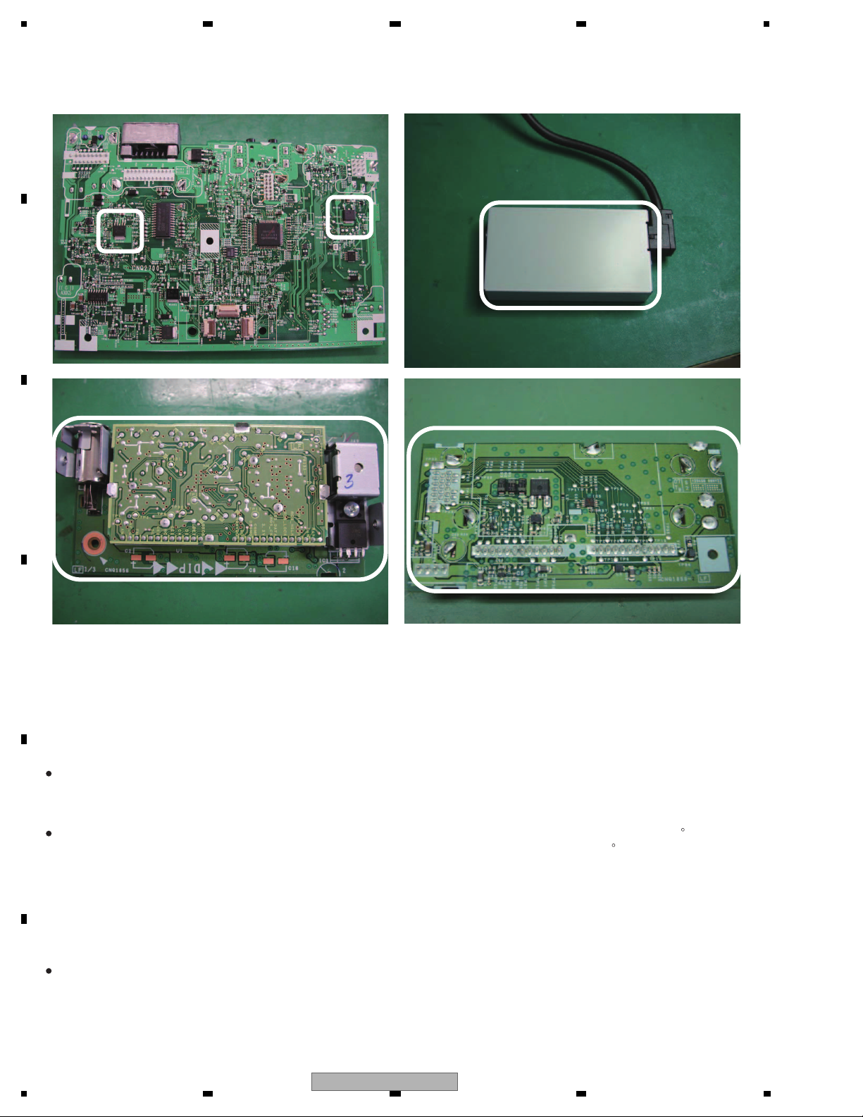
11. Hot areas
White area: Hot area. Be careful not to burn yourself
DVD Amp Unit
A
B
Tuner Box
C
D
1.2 NOTES ON SOLDERING
For environmental protection, lead-free solder is used on the printed circuit boards mounted in this unit.
Be sure to use lead-free solder and a soldering iron that can meet specifications for use with lead-free solders for repairs
accompanied by reworking of soldering.
E
Compared with conventional eutectic solders, lead-free solders have higher melting points, by approximately 40 C.
Therefore, for lead-free soldering, the tip temperature of a soldering iron must be set to around 373 C in general, although
the temperature depends on the heat capacity of the PC board on which reworking is required and the weight of the tip of
the soldering iron.
Compared with eutectic solders, lead-free solders have higher bond strengths but slower wetting times and higher melting
temperatures (hard to melt/easy to harden).
The following lead-free solders are available as service parts:
Parts numbers of lead-free solder:
GYP1006 1.0 in dia.
GYP1007 0.6 in dia.
F
GYP1008 0.3 in dia.
6
1234
AVH-P5150DVD/XN/RC

5 678
2. SPECIFICATIONS
2.1 SPECIFICATIONS
A
General
Rated power source..............14.4 V DC
(allowable voltage range:
12.0 V to 14.4 V DC)
Grounding system................. Negative type
Max. current consumption
...............................................10.0 A
Backup current ...................... 5.0 mA or less
Dimensions (W × H × D):
DIN
Chassis........................... 180 mm × 50 mm × 165
mm
Nose................................ 188 mm × 58 mm × 33 mm
D
Chassis................. 178 mm × 50 mm × 165
mm
Nose....................... 170 mm × 46 mm × 28 mm
Weight .................................... 2.4 kg
Display
Screen size/aspect ratio...... 7.0 inch wide/16:9
(effective display area: 154
× 87 mm)
Pixels ....................................... 336 960 (1 440 × 234)
Display method .................... TFT active matrix, transmis-
sive type
Color system.......................... NTSC/PAL/PAL-M/SECAM
compatible
Durable temperature range (power off)
.............................................. -20 °C to +80 °C
Angle adjustment ................. 50° to 110°
(initial settings: 90°)
Audio
Maximum power output ...... 50 W × 4
50 W × 2/4
(for subwoofer)
Continuous power output .. 22 W × 4 (50 Hz to 15 000
Hz, 5 % THD, 4
channels driven)
Load impedance ................... 4
Preout max output level ...... 4.0 V
Equalizer (3-Band Parametric Equalizer):
Low
Frequency.............. 40/80/100/160 Hz
Q Factor ................. 0.35/0.59/0.95/1.15 (+6 dB
Gain ......................... ±12 dB
Mid
Frequency.............. 200/500/1k/2k Hz
Q Factor ................. 0.35/0.59/0.95/1.15 (+6 dB
to 8 ×4
4
to 8 ×2+2 ×1
when boosted)
when boosted)
+ 70 W × 1/2
load, both
Gain ......................... ±12 dB
High
Frequency.............. 3.15k/8k/10k/12.5k Hz
Q Factor ................. 0.35/0.59/0.95/1.15 (+6 dB
when boosted)
Gain ......................... ±12 dB
HPF:
Frequency.......................50/63/80/100/125 Hz
Slope................................–12 dB/oct
Subwoofer (mono):
Frequency.......................50/63/80/100/125 Hz
Slope................................–18 dB/oct
Gain .................................. +6 dB to – 24 dB
Phase ..............................Normal/Reverse
Bass boost:
Gain ................................. +12 dB to 0 dB
DVD Player
System ..................................... DVD video, DVD-VR, Video
CD, CD, WMA, MP3, AAC,
DivX system
Usable discs .......................... DVD video, Video CD, CD,
CD-R/RW, DVD-R/RW/RDL
Region number:
for Middle East Asian and South African models
..................................... 2
for Southeast Asian models
..................................... 3
for South American and Oceanian models
..................................... 4
Frequency response............. 5 Hz to 44 000 Hz(with DVD,
at sampling frequency 96
kHz)
Signal-to-noise ratio............. 96 dB (1 kHz) (IEC -A net-
work) (RCA level)
Output level:
Video............................... 1.0 Vp-p/75
Number of channels ............ 2 (stereo)
MP3 decoding format ..........MPEG-1 & 2 Audio Layer 3
WMA decoding format ....... Ver. 7, 7.1, 8, 9, 10, 11 (2ch
audio)
(Windows Media Player)
AAC decoding format........... MPEG-4 AAC (iTunes en-
coded only) (.m4a)
(Ver. 8.0 and earlier)
DivX decoding format...........Home Theater Ver. 3, 4, 5.2
(.avi, .divx)
(±0.2 V)
USB
USB standard specification
............................................... USB 2.0 full speed
Maximum current supply .... 500 mA
USB Class............................... MSC (Mass Storage Class)
File system.............................. FAT16, FAT32
B
C
D
E
56
AVH-P5150DVD/XN/RC
F
7
8
7

1234
MP3 decoding format ......... MPEG-1 & 2 Audio Layer 3
WMA decoding format ....... Ver. 7, 7.1, 8, 9, 10, 11 (2ch
A
AAC decoding format.......... MPEG-4 AAC (iTunes en-
WAV signal format ................ Linear PCM & MS ADPCM
audio)
(Windows Media Player)
coded only) (.m4a)
(Ver. 8.0 and earlier)
(Non-compressed)
FM tuner
Frequency range................... 87.5 MHz to 108.0 MHz
Usable sensitivity.................. 9 dB f (0.7 μV/75
S/N: 30 dB)
B
Signal-to-noise ratio............. 72 dB (IEC-A network)
, mono,
AM tuner
Frequency range................... 531 kHz to 1 602 kHz (9 kHz)
530 kHz to 1 640 kHz (10
kHz)
Usable sensitivity.................. 25 μV (S/N: 20 dB)
Signal-to-noise ratio............. 62 dB (IEC-A network)
Infrared remote control
Wavelength............................. 945 nm
C
Output ......................................typ; 10 mw/sr per Infrared
LED
Note
Specifications and the design are subject to modifications without notice due to improvements.
2.2 DISC/CONTENT FORMAT
D
E
is a trademark of DVD Format/Logo Licensing Corporation.
F
8
1234
AVH-P5150DVD/XN/RC
5 678
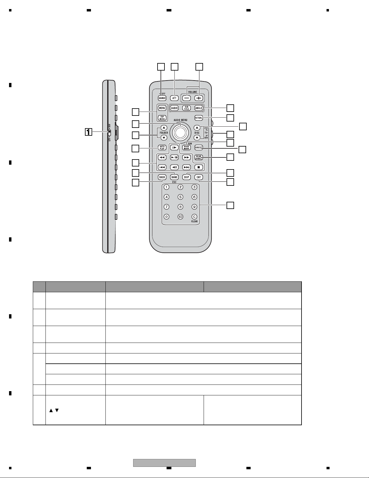
2.3 PANEL FACILITIES
A
B
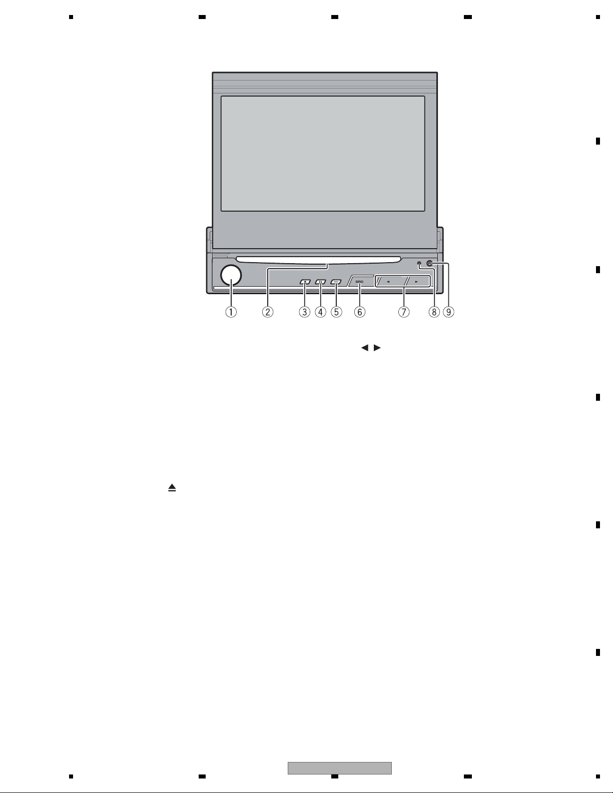
What ’s what
Head unit
1 VOLUME/MUTE button
Rotate it to increase or decrease the volume.
Press to cut the sound.
2 Disc loading slot
Insert a disc to play.
3 EJECT (
Press to eject a disc from this unit.
4 EQ button
Press to select various equalizer curves.
5 OPEN/CLOSE button
Press to open or close the LCD panel.
Press and hold to turn the LCD panel horizontal temporarily from upright position.
6 SRC button
This unit is turned on by selecting a source.
Press to cycle through all the available
sources.
) button
/ (TRACK) buttons
7
Press to do manual seek tuning, fast forward, reverse and track search controls.
8 RESET button
Press to return to the factory settings (initial
settings).
9 DETACH button
Press to remove the front panel from the
head unit.
C
D
E
56
AVH-P5150DVD/XN/RC
F
7
8
9
1234
A
2 3
21
B
1
20
19
4
5
6
7
8
9
18
17
16
15
C
10
11
12
13
14
D
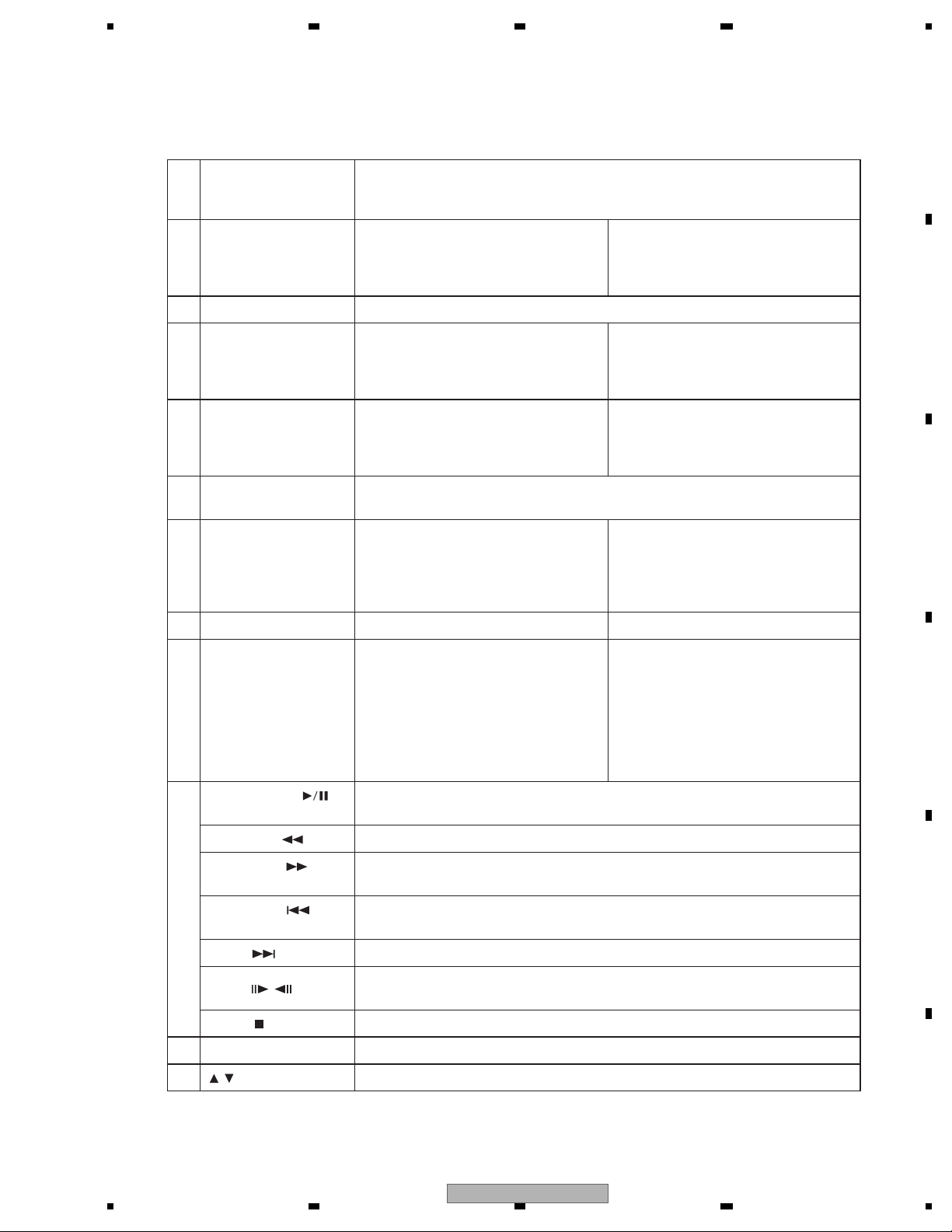
Remote control
Button names AVH mode DVD mode
Remote control selec-
1
tion switch
2 SRC button
3ATTbutton
4 VOLUME buttons Press to increase or decrease the volume.
E
F
AUDIO button Press to change the audio language during DVD playback.
5
SUBTITLE button Press to change the subtitle language during DVD playback.
ANGLE button Press to change the viewing angle during DVD playback.
6 RETURN button Press to display the PBC (playback control) menu during PBC playback.
7
/ buttons (DISC ) Not used.
Switch to change the setting of the remote control. For details, refer toSetting remote control code type.
Press to cycle through all the available sources. Press and hold to turn the source
off.
Press to quickly lower the volume level by about 90%. Press once more to return to
the original volume level.
Remote control code: AVH or B
Not used.
Remote control code: A
Press to select the next/previous disc.
10
1234
AVH-P5150DVD/XN/RC
5 678
A
Remote control opera-
8
tion mode switch
BOOK MARK button/
9
PGM button
Switch the operation mode between AVH, DVD and TV modes. Normally, set to
AVH. For details, refer toUsing the remote control operation mode switchon the
next page.
Press to operate the preprogrammed
functions for each source. (Refer to
Using the PGM button.)
10 DIRECT button Not used.
11 REAR SOURCE button Not used.
12 DISPLAY button Press to select different displays.
ENTERTAINMENT but-
13
ton
Not used.
Press0 to 10 to input numbers. Buttons
0 to 10 buttons, CLEAR
14
button
1 to 6 can operate the preset tuning for
the tuner or disc changing for DVD
player or multi-CD player. Press CLEAR
to clear the input numbers.
Press to turn the bookmark function on
or off when your DVD player features
bookmark function. For details, refer to
DVD player’s operation manual.
B
Remote control code: AVH
Not used.
Remote control code: A or B
Press to turn the DVD player on or off.
Remote control code: AVH
Not used.
Remote control code: A or B
Press to select different displays.
C
Press to select a menu item on a video
CD featuring PBC (playback control).
15 BACK button Press to return to the previous display. Not used.
Press to select the tuner band when
16 BAND/ESC button
tuner is selected as a source. Also used
to cancel the control mode of functions.
Press to switch mode between compressed audio and audio data (CD-DA)
when playing discs with compressed
audio and audio data (CD-DA) such as
Press to switch mode between compressed audio and audio data (CD-DA)
when playing discs with compressed
audio and audio data (CD-DA) such as
CD-EXTRA and MIXED-MODE CDs.
CD-EXTRA and MIXED-MODE CDs.
PLAY/PAUSE (
button
REVERSE (
FORWARD (
ton
17
PREVIOUS (
ton
NEXT (
STEP (
STOP (
) button Press to go to the next track (chapter).
/ ) buttons
) button Press to stop playback.
)
Press to switch sequentially between playback and pause.
) button Press to perform fast reverse.
) but-
) but-
Press to perform fast forward.
Press to return to the previous track (chapter).
Press to move ahead one frame at a time during DVD/VideoCD playback. Press
and hold for one second to activate slow playback.
18 AUTO PLAY button Press to turn the DVD auto-playback function on or off.
D
E
19
/ buttons (FOLDER ) Press to select the next/previous folder.
AVH-P5150DVD/XN/RC
56
F
7
8
11
1234
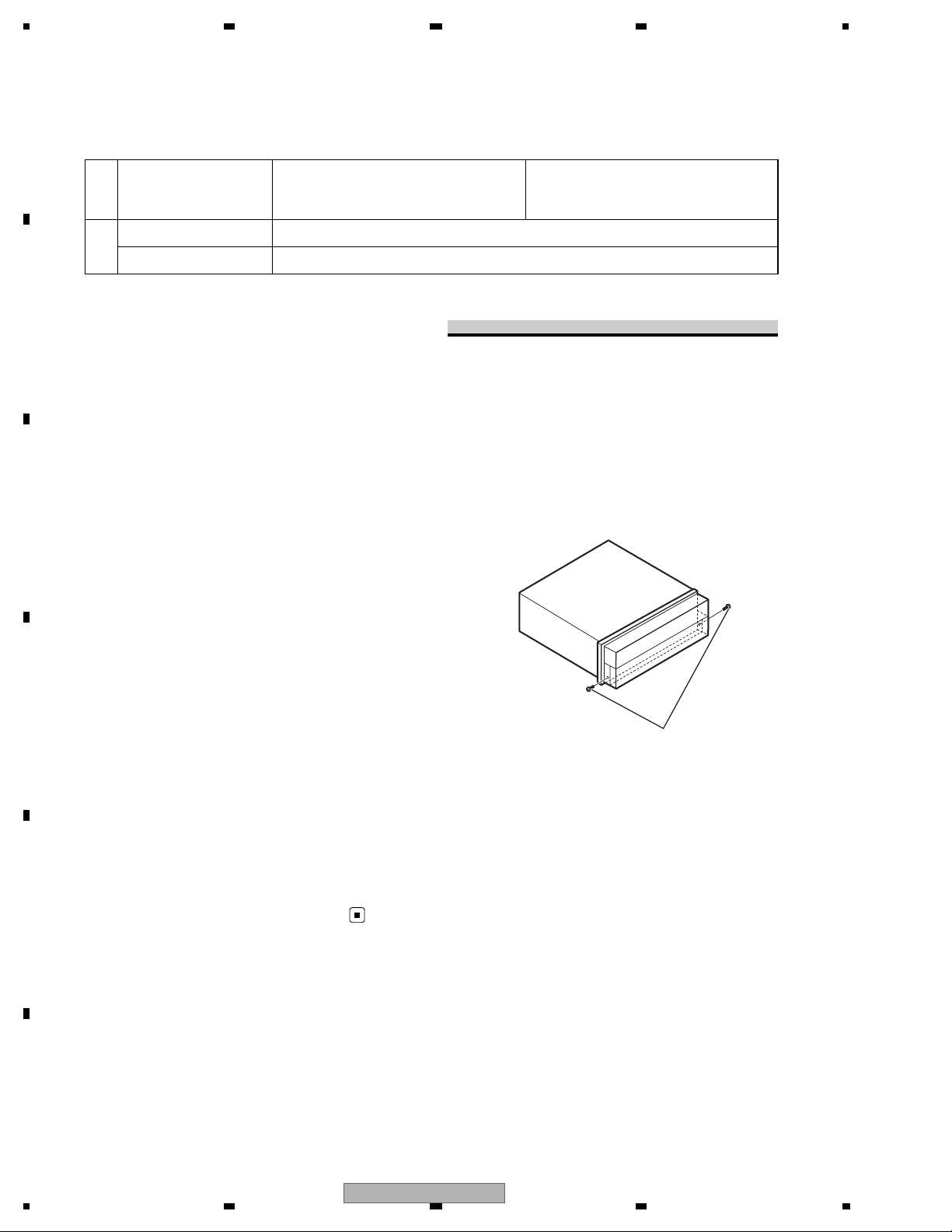
A
Move to do fast forward, reverse and
20 Thumb pad
MENU button Press to display the DVD menu during DVD playback.
21
TOP MENU button Press to return to the top menu during DVD playback.
B
Using the remote control operation
track search controls. Click to recall
MENU.
Fastening the front panel
Move to select a menu on the DVD
menu.
mode switch
There are three remote control operation
modes on the remote control.
AVH mode operation
When operating this unit by remote control,
the mode is normally switched toAVH.
C
DVD mode operation
If you do not plan to detach the front
panel, the front panel can be fastened
with supplied screws.
• Fix the front panel to the unit
using screws and holder after
removing the trim ring.
If you switch the mode to DVD, the thumb pad
and 0 to 10 operations are changed for the
DVD player.
When you want to operate the follow-
•
ing functions, switch the mode to DVD:
• When operating the DVD menu by using
the thumb pad. (Refer toOperating the DVD
D
menu.)
• When operating the PBC menu by using 0
to 10. (Refer toPBC playback.)
Screws
JGZ20P070FTC
TV mode operation
TV operations available with a Pioneer TV tuner
(e.g. GEX-P5750TV(P)) can be controled with
AVH mode. TV mode is not used with this
unit.
• For details concerning operation, refer to
E
F
12
the TV tuner’s operation manuals.
AVH-P5150DVD/XN/RC
1234
5 678
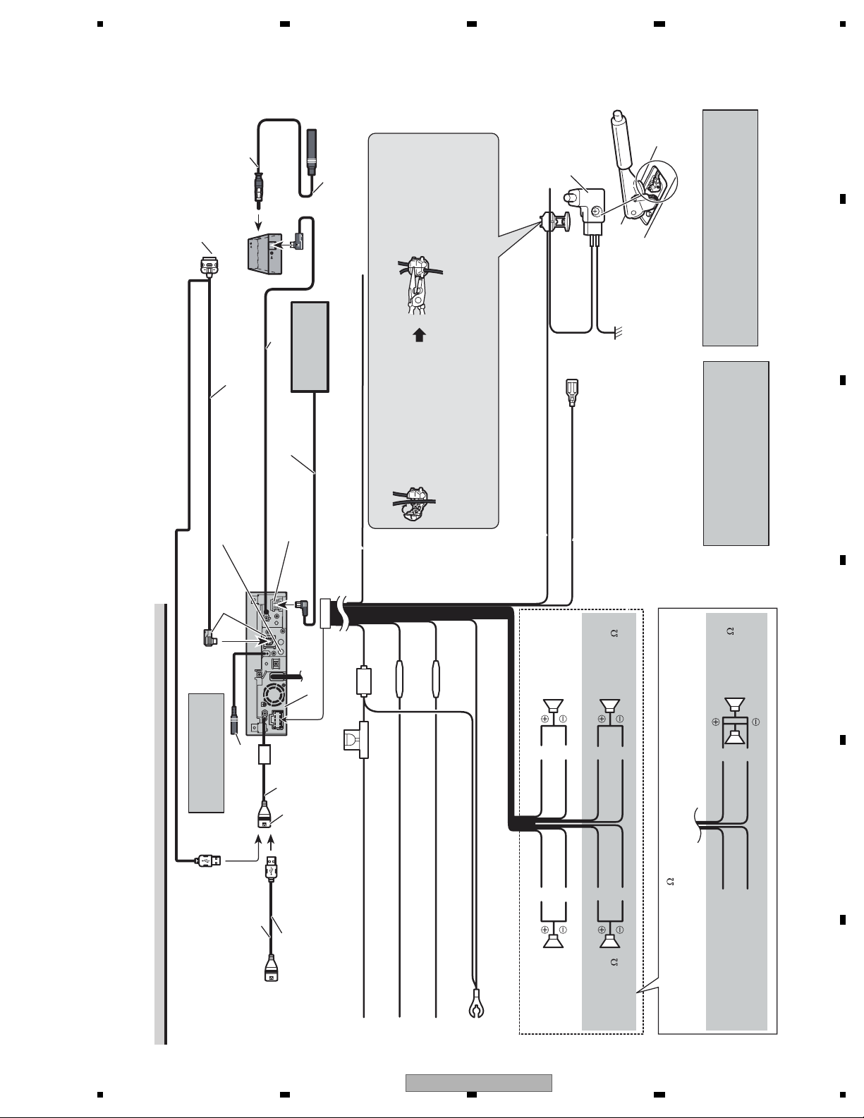
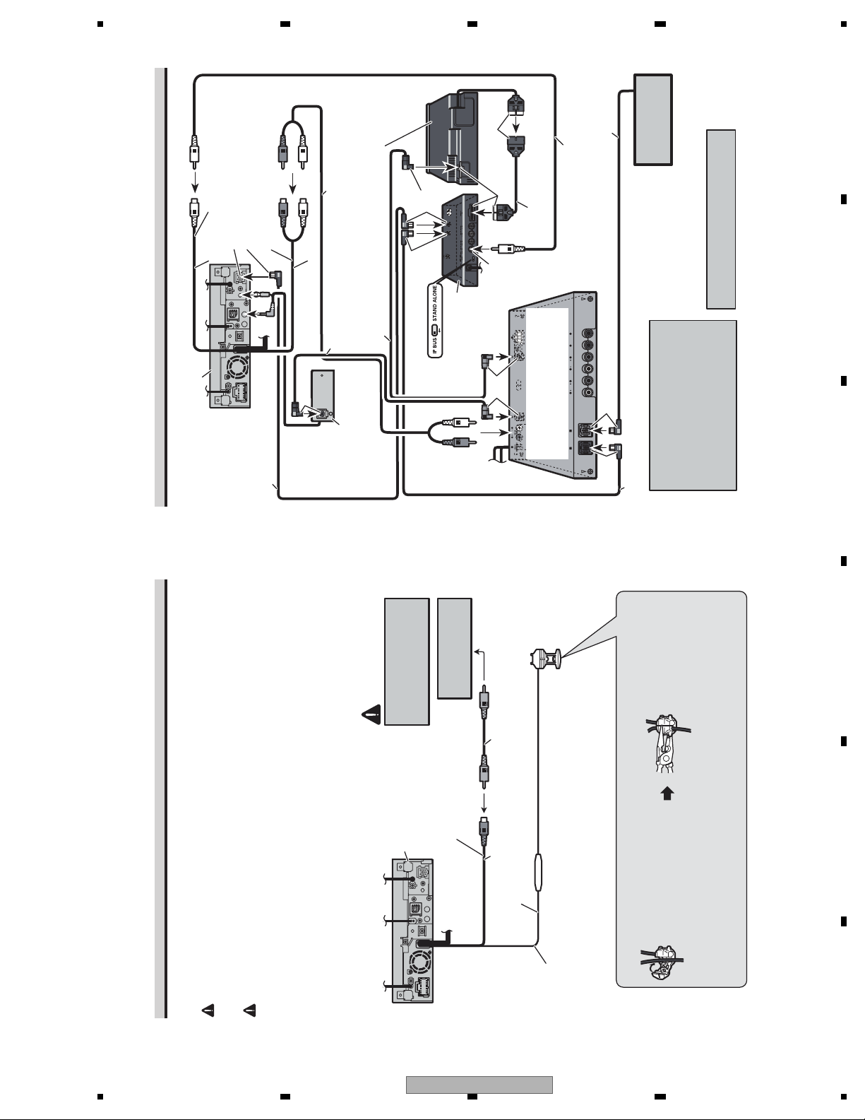
2.4 CONNECTION DIAGRAM
80 cm
Antenna cable
(supplied)
Parking brake
switch
A
Tuner box (supplied)
Dock connector
Connect to separately sold iPod.
80 cm
Interface cable (e.g., CD-IU205V)
(sold separately)
Wired remote input
Hard-wired remote control adaptor
can be connected (sold separately).
Gray
Multi-CD player
IP-BUS cable
IP-BUS input
(Blue)
needle-nosed pliers.
2. Clamp firmly with
Ground side
Power supply side
(sold separately)
1. Clamp the lead.
consult the vehicle Owner’s Manual or dealer.
Note:
• The position of the parking brake switch depends on the vehicle model. For details,
Yellow/black
Connection method
If you use an equipment with Mute function, wire this lead to the Audio Mute lead on
that piece of equipment. If not, keep the Audio Mute lead free of any connections.
Light green
Used to detect the ON/OFF status of the parking brake. This
lead must be connected to the power supply side of the parking
brake switch.
Blue/white
Connect to system control terminal of the power
amp or auto-antenna relay control terminal
)
rekaepstnorFrekaepstnorF
Operation Manual). The subwoofer output of this unit
Note:
• Change the initial setting of this unit (refer to the
With a 2 speaker system, do not connect
anything to the speaker leads that are not
connected to speakers.
When you connect the separately sold multi-
channel processor (e.g., DEQ-P7650) to this
(max. 300 mA 12 V DC).
unit, do not connect anything to the speaker
)
is monaural.
leads and system remote control
(blue/white).
B
C
D
20 cm
Use a mini plug cable to
connect with auxiliary
equipment.
AUX jack (3.5 ø)
1.5 m
This product
Fuse (10 A)
USB input
USB cable (supplied)
Connect to separately sold
USB device.
Fuse resistor
Fuse resistor
Yellow
Connect to the constant 12 V supply terminal.
Red
Connect to terminal controlled by ignition switch (12 V DC).
Orange/white
Connect to lighting switch terminal.
Connecting the power cord
56
AVH-P5150DVD/XN/RC
Rear speaker or
Subwoofer (4
Gray/blackWhite/black
White Gray
Black (chassis ground)
Connect to a clean, paint-free metal location.
Green Violet
Green/black Violet/black
)
Left Right
Rear speaker or
Subwoofer (4
7
Subwoofer (4
× 2
Violet
Violet/black
E
Green
), be sure to connect with Violet and Violet/black leads of this unit.
Do not connect anything to Green and Green/black leads.
When using a subwoofer of 70 W (2
Green/black
Not used.
8
F
13

1234
A
Power amp
(sold separately)
Rear speaker
Power amp
(sold separately)
B
System remote control
Left Right
Connect with RCA cables
(sold separately)
Front speaker Front speaker
or subwoofer
Rear speaker
or subwoofer
Perform these connections when
using the optional amplifier.
Manual). The subwoofer output of this unit is monaural.
Note:
• Change the initial setting of this unit (refer to the Operation
C
D
Front output
(FRONT OUTPUT)
15 cm
Rear output or subwoofer output
(REAR/SUBWOOFER/DEQ OUTPUT)
E
15 cm
When you connect the separately sold multi-
channel processor (e.g., DEQ-P7650) to this
unit, do not connect anything to the speaker
leads and system remote control
(blue/white).
Blue/white
Connect to system control terminal of the power
amp or auto-antenna relay control terminal
(max. 300 mA 12 V DC).
When you connect the multi-channel
processor to this unit, refer to multi-channel
processor’s installation manual for the
connection method.
This product
F
14
When connecting to separately sold power amp
AVH-P5150DVD/XN/RC
1234
5 678
A
Black
IP-BUS cable
Multi-CD player
(sold separately)
RCA cable (supplied
with DVD player)
RCA cable (supplied with
Video input
(VIDEO INPUT)
IP-BUS input (Blue)
25 cm
This product
multi-channel processor)
DEQ output (REAR/
SUBWOOFER/DEQ OUTPUT)
Blue
15 cm
Optical cable (supplied with
Black
DVD player (e.g., XDV-P650)
(sold separately)
Optical cable (sold
separately)
multi-channel processor)
Black
Blue
Hide-away unit (supplied
with DVD player)
Black
25 pin cable (supplied
with DVD player)
Front video output
(Yellow)
Blue
Multi-channel processor
(e.g., DEQ-P7650)
(sold separately)
You can use only one video component
with this unit.
B
Optical cable connection box
(e.g., CD-DD25)
IP-BUS cable
(supplied with DVD
player)
(sold separately)
When connecting with a multi-channel processor
Rear view camera
CAUTION
You must use a camera
which outputs mirror
reversed images.
Rear view camera input
(REAR VIEW
This product
CAMERA IN)
To video output
RCA cable
(sold separately)
20 cm
Black Blue
When you connect a separately sold
DVD player to the separately sold
multi-channel processor, the optical
IP-BUS cable (supplied with
multi-channel processor)
2. Clamp firmly with
cable from DVD player must be
needle-nosed pliers.
connected to the optical cable 2 input
(OPT. IN2) of the multi-channel
processor.
C
D
E
Fuse resistor
15 cm
Violet/white
CAUTION
WARNING
When this product is used with a rear view camera, it is possible to automatically switch
from the video to rear view image when the gear shift is moved to REVERSE (R).
USE INPUT ONLY FOR REVERSE OR MIRROR IMAGE REAR VIEW CAMERA. OTHER USE MAY
RESULT IN INJURY OR DAMAGE.
The screen image may appear reversed.
When connecting with a rear view camera
function for entertainment purposes.
• The rear view camera function is to be used as an aid for backing into a tight parking spot. Do not use this
• Objects in the rear view may appear closer or more distant than they actually are.
•
AVH-P5150DVD/XN/RC
56
1. Clamp the lead.
connecting the rear view camera.
Note:
Of the two lead wires connected to the back lamp, connect the
one in which the voltage changes when the gear shift is in the
REVERSE (R) position. This connection enables the unit to
sense whether the car is moving forwards or backwards.
Connection method
7
• It is necessary to set CAMERA POLARITY properly in SYSTEM MENU when
8
15
F

1234
A
Display with
RCA input jacks
(sold separately)
External video
component
(sold separately)
To video input
B
This product
Rear monitor output
(REAR MONITOR OUTPUT)
20 cm
C
When connecting the external video component and the display
D
To video output
RCA cables (sold separately)
Video input
(VIDEO INPUT)
25 cm
To audio outputs
Audio input
(AUDIO INPUT)
Hook fastener
• It is necessary to set AV INPUT to VIDEO in SYSTEM MENU when connecting the
r
Loop fastene
external video component.
multi-DVD player.
• It is necessary to set AV INPUT to S-DVD in SYSTEM MENU when connecting a
This product’s rear video output is for connection of a display to enable passengers in the
rear seats to watch the DVD or Video CD.
When using a display connected to rear video output
WARNING
while driving.
• NEVER install the display in a location that enables the Driver to watch the DVD or Video CD
Wrap with the protection tape
Optical cable
E
WARNING
operation of safety devices such as airbags is pre-
vented by this unit. Otherwise, there is a danger of
a fatal accident.
operation of the brake may be prevented.
F
16
Connecting and installing the
optical cable connection box
• Avoid installing this unit in locations where the
1234
Otherwise, it may result in a traffic accident.
• Avoid installing this unit in locations where the
installing the optical cable
Install the optical cable connection box
using the hook and loop fastener in the
connection box with the hook and
• When
Installing the optical cable
connection box
CAUTION
tener or lock tie. If this unit is loose, it disturbs
driving stability, which may result in a traffic
accident.
• Fix this unit securely with the hook and loop fas-
ample space of the console box.
loop fastener.
this unit. If other parts are used, this unit may be
damaged or could dismount itself, which leads to
an accident or other problems.
water is likely to be spilled on the unit. Incursion
• Install this unit using only the parts supplied with
of water into the unit may cause smoke or fire.
• Do not install this unit near the doors where rain-
Connecting the optical cable
1. Connect the optical cable and
AVH-P5150DVD/XN/RC
Wrap the optical cable and connection
box with the protection tape and fasten
with the power code using the lock tie.
connection box with the lock tie.
• When installing the optical cable
Screw
Connect the optical cable so that it
does not protrude from the unit, as
shown in the illustration. Fasten the
ground lead to the protrusion on the
ground lead to the main unit.
back of the unit.
Fasten with the lock tie
Connect the optical cable to the
optical cable connection box.
2.

5 678
3. BASIC ITEMS FOR SERVICE
3.1 CHECK POINTS AFTER SERVICING
To keep the product quality after servicing, please confirm following check points.
No. Procedures Check points
1 Confirm whether the customer complain has
been solved.
If the customer complain occurs with the
specific media, use it for the operation check.
2 Flap-mecha Check the operation of the flap mechanism. The flap mechanism operation must be
3 DVD Measure playback error rates at the
innermost and outermost tracks by using the
test mode with the following disc.
DVD test disc (GGV1025)
The customer complain must not be
reappeared.
Display, video, audio and operations must be
normal.
smooth without making the noise and
scratches.
Deterioration of mecha-drive can be checked.
The error rate must be less than the
threshold value.
(Refer to the chapter of DIAGNOSIS for the
threshold value.)
A
B
4 DVD Play back a DVD.
(Menu operation; Title/chapter search)
5 CD Play back a CD.
(Track search)
6 FM/AM tuner Check FM/AM tuner action.
(Seek, Preset)
Display, video, audio and operations must be
normal.
Display, audio and operations must be
normal.
Display, audio and operations must be
normal.
Switch band to check both FM and AM.
7 Check whether no disc is inside the product. The media used for the operating check must
be ejected.
8 Appearance check No scratches or dirt on its appearance after
receiving it for service.
See the table below for the items to be checked regarding video and audio:
Item to be checked regarding video Item to be checked regarding audio
Block-noise Distortion
Horizontal noise Noise
Dot noise Volume too low
Disturbed image (video jumpiness) Volume too high
Too dark Volume fluctuating
Too bright Sound interrupted
Mottled color
C
D
56
AVH-P5150DVD/XN/RC
E
F
7
8
17
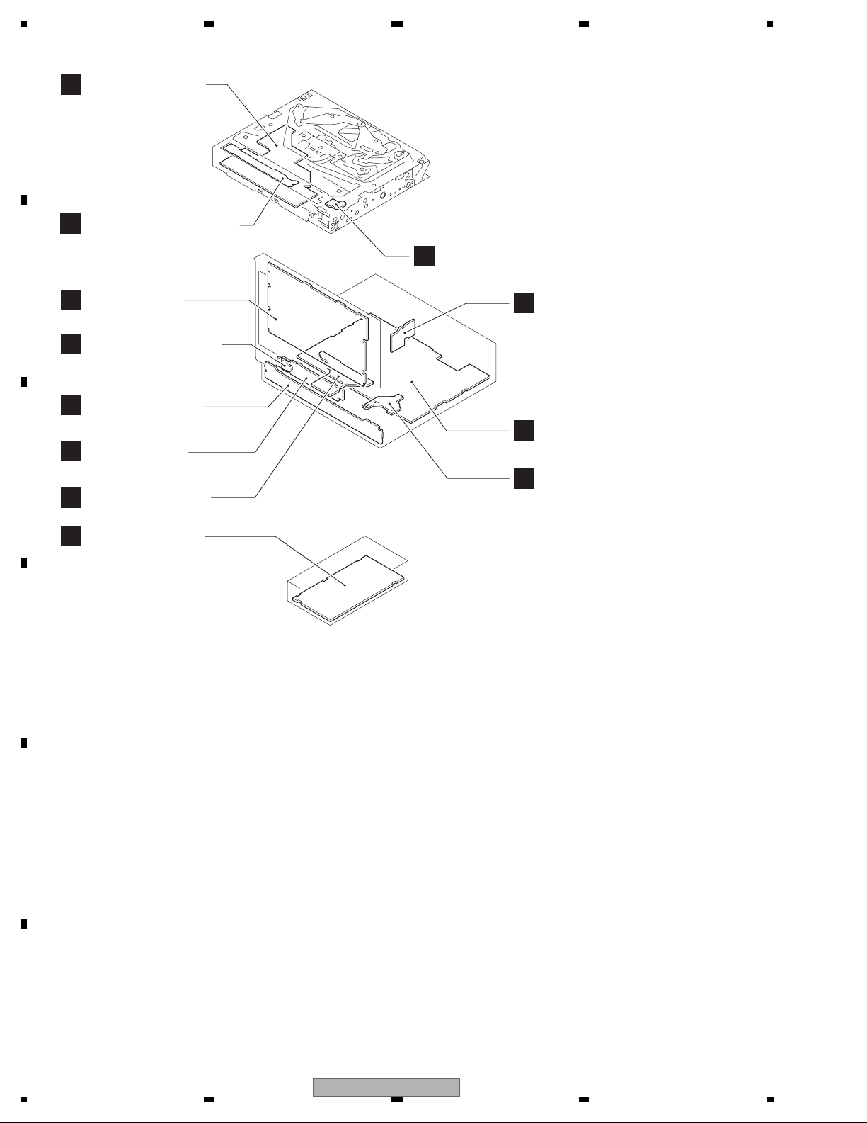
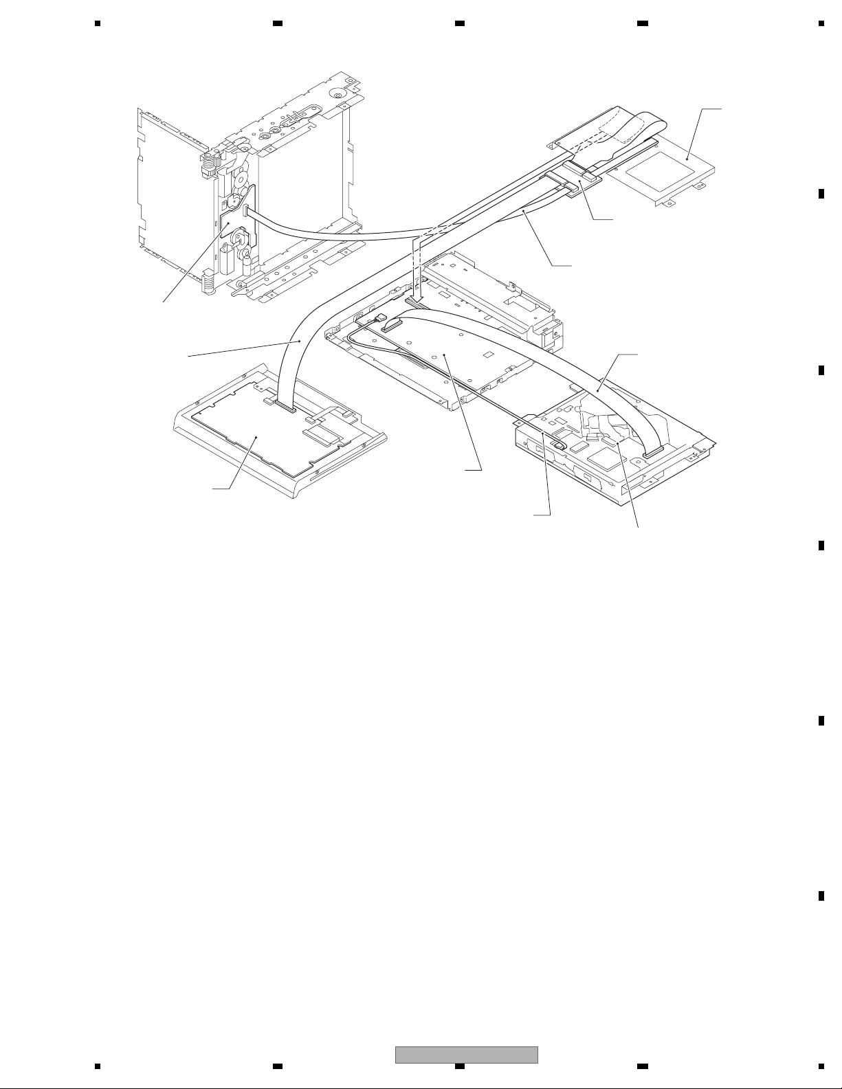
1234
3.2 PCB LOCATIONS
DVD Core Unit
D
A
(MS5AVCOD)
Compound Unit (A)
E
Compound Unit (B)
F
B
C
D
E
Monitor PCB
G
Switch PCB Unit
K
C
Keyboard Unit
H
Inverter PCB
Main PCB Unit
J
Tuner Box Unit
I
iPod Connector Unit
B
DVD Amp Unit
A
Volume PCB Unit
L
Unit Number : CWN3852(RC)
Unit Number : CWN3853(RD)
Unit Number : CWN3854(RI)
Unit Name : DVD Amp Unit
Unit Number :
Unit Name : Keyboard Unit
Unit Number :
Unit Name : iPod Connector Unit
Monitor Unit
Consists of
Monitor PCB
Inverter PCB
Unit Number : CWN4088
Unit Name : Monitor Unit
Unit Number : CWN3130
Unit Name : Tuner BOX Unit
Unit Number : CXX2316
Unit Name : Main PCB Unit(SERVICE)
Unit Number : CZW5029
Unit Name : Switch PCB Unit
Unit Number : CZW5028
Unit Name : Volume PCB Unit
Unit Number : YWX5005
Unit Name : DVD Core Unit
Unit Number : CWX3595
Unit Name : Compound Unit(A)
Unit Number : CWX3559
Unit Name : Compound Unit(B)
F
18
1234
AVH-P5150DVD/XN/RC
5 678
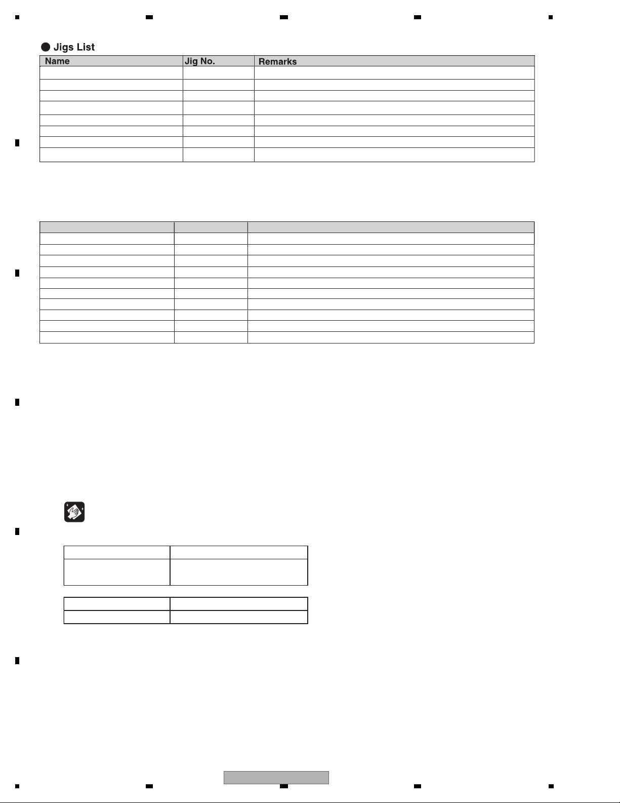
3.3 JIGS LIST
Main PCB Unit
GGD1170
40-Pin FFC
Monitor PCB
DVD Amp Unit
GGF1461
40-Pin + 20-Pin Relay PCB
GGD1209
20-Pin FFC
Bracket
GGD1284
40-Pin FFC BBR
A
B
C
Cord
CDE8589
DVD Mechanism Module
D
E
56
AVH-P5150DVD/XN/RC
F
7
8
19
1234
DVD-Video GGV1025 Skew adjustment
A
CD-DA TCD-782 Skew adjustment
TORX driver(T2) GGK1095 Skew adjustment
Bond GEM1033 Skew adjustment
40-Pin FFC GGD1170 Monitor PCB <--> Relay PCB
20-Pin FFC GGD1209 Main PCB Unit <--> Relay PCB
40-Pin FFC BBR GGD1284 DVD Mechanism Module <--> DVD Amp Unit
40-Pin + 20 Pin Relay PCB GGF1461 DVD Amp Unit <--> Monitor PCB, Main PCB Unit
B
- Grease List
Name
Grease
Grease
Grease
Grease
Locking agents
Grease
Grease
Grease
Grease
C
Grease
Jig No.
GEM1024
GEM1043
GEM1045
GEM1050
1401M
GEM1011
GEM1047
GEM1071
GEM1072
GEM1070
Remarks
DVD Mechanism Module and Chassis
DVD Mechanism Module and Chassis
DVD Mechanism Module
DVD Mechanism Module
DVD Mechanism Module (1401M:produced by THREE BOND)
Chassis
Chassis
Chassis
Chassis
Chassis
D
3.4 CLEANING
Before shipping out the product, be sure to clean the following portions by using the prescribed cleaning tools:
Portions to be cleaned Cleaning tools
DVD pickup lenses Cleaning liquid : GEM1004
Cleaning paper : GED-008
E
F
Portions to be cleaned Cleaning tools
Fans Cleaning paper : GED-008
20
1234
AVH-P5150DVD/XN/RC

5 678
A
B
C
D
E
56
AVH-P5150DVD/XN/RC
F
7
8
21
1234
9
2
DA3
A
M
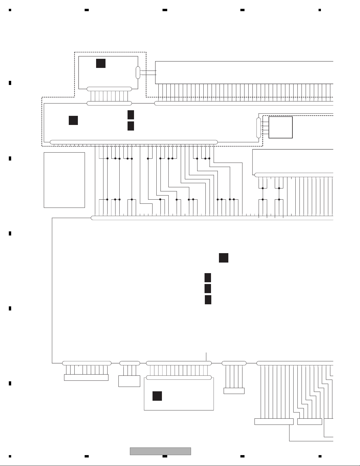
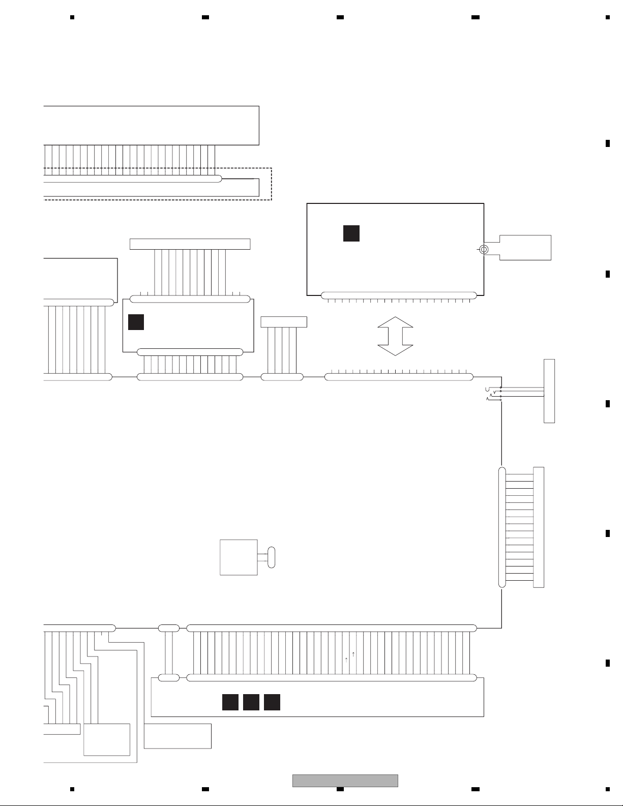
4. BLOCK DIAGRAM
4.1 OVERALL CONNECTION DIAGRAM
A
MONITOR UNIT CWN4088
H
LCD MODULE
CWX3264
GND
CPH
NC
GND
20
21
22232425262728293031323334
CN5002
PNLYV
PNLXV
PNLADX
PNLADY
NCNCNC
GND
GNDFL
GNDFL
252627
VDD2
VDD2
NC
VDD2
1
2
3
4
1234567
BUP
BUP
222324
192021
L/R
BUP
18
DC2
DC3
LOAD
DC4
DC5
CN5501
TOUCH
PANEL
CSX1115
DRAIVE UNIT
CXC9160
8
NC
GND
GND
DGND
GND
1314151617
DB5
DB4
DC0
DC1
DB3
DB2
353637
383940
CN101
9
101112131415161718
LFTSW
NC
SENSPW
ANGL0SW
VDD
MTRSEL
9
101112
MTR1
DB1
DA4
DA5
DB0
414243
1
MTR2
MTRS
LIFTPUL
MTRPW
678
345
CN5201
9
10
10
1/2
G
2/2
G
CN5001
21222324252627
2
1
STV1
STV2
OE
U/D
CPV
9
NC
VGL
VCOM
VCOM
1
2345678
NC
MONITOR PCB(MONITOR)
MONITOR PCB(OSD)
678
15
14
1617181920
9
101112
13
10
GND
111213
5
NC
VGH
NC
141516
234
STH2
1
VDD1
VDD1
NC
171819
GND
INVERTER PCB
CN5602
1
234
567
8
GNDFL
PWRFL8PWRFL9PWRFL
GNDFL4GNDFL
3
5
CN5004
282930
NC
7
6
INVBST1DIMDTY2INVPUL
B
39
40
G
35
37
38
36
MONITOR PCB
33
31
32
34
REMOTE
CONTROL
ASS'Y
CXC6317
C
OSDGND
GND
GNDV
GNDV
MONVBS
585960
OSDGND
OSDGND
NC
SWVDD33V
SWVDD33V
NC
SWVDD33V
495051525354555657
REM
GNDP
NC
NC
464748
434445
MFLPW
PWRVI
404142
PWRVI
GNDP
NC
NC
NC
PWRFL
M_SRX
S_MTX
PWRFL
PWRFL
NC
GNDD
MONRST
313233343536373839
GNDFL
GNDD
GNDD
28
29
30
CN441
DVD AMP UNIT
A
D
DVD AMP UNIT(AMP)
1/3
A
DVD AMP UNIT(SYSTEM)
2/3
A
DVD AMP UNIT(POWER SUPPLY)
3/3
A
11
BUSL-
JA951
OPTG
OPTSENS
OPTG
1
3
2
DIGITAL
OUT
OPTOUT
4
RED
1
1
GREEN
2
2
BLUE
3
3
ILMB6KEY1
SWVDD33
4
5
5
4
CN3001
CN851
RESET9ILMA10ROT1
REM
7
8
679
8
ROT2
DGND
KEY2
DSENS
ILMGND
13
11
12
14
15
12
10
13
14
15
11
CN852
12345
VGND
AUXV
AUXR
AGND
AUXL
AGND1FL
AGND
2
3
E
123
BUS+
GND
GND
JA751
4
567
GNDNCBUS-
BUSL+
ABO
8
9
BUSR+
10
BUSR-
IP-BUS INPUT
RL4FR
AGND6RR7AGND
5
CN121
VCR_L
VCRAGND
8
9
VCR_R11VCRAGND
10
12
VCR_V
VCRVGND
14
13
B.CAMERA15BC_VGND16VGND
17
REARVOUT
18
MINIJACK
KEYBOARD UNIT
C
F
RCA OUT
VCR IN
RE
CA
IN
22
1234
AVH-P5150DVD/XN/RC
5 678
VCR
R
A
DB3
DB1
DB4
DB2
36
37
383940
UNIT
0
01
12131415161718
MTRSEL
ANGL0SW
MTR2
LFTSW
MTR1
678
9
DA4
DA5
DB0
4142434445
MTRS
LIFTPUL
MTRPW
345
DA3
19
ANGLEIN
2
DA2
20
1
DA1
DA0
V9
V10
46
47
48
B
CN1901
GND
V0
V3
V7V2V5
V4
V6
49
V8
505152
53545556575859
STH1
V1
60
IPOD
IPOD_AG
RT1
RT2
9
8
456
13
12
7
11
10
JA1901
LOUT
ACC_ID
RXIPOD
ROUT
VOUT
ACCDET
ACC_PW
IPODGND
IPOD_VG
GND
GND
iPod CONNECTOR UNIT
LOUT
IPODAG
IPODVG
ACCDET
VOUT
ACCPW
IPODGND
IPODAG
ROUT
4
1
2
3
12345
5
678
6
CN901
IPODTX
ACCID
9
11
12
10
7
8
9
101112
TXIPOD
3
FWGND
IPODRX
13
13
2
FWPWR
14
14
B
TUNER BOX UNIT
I
DGND
RDS_CK
DGND
LDET
DGND
RDS_LOC
DSEN
CE1
BEGND
RDS_DATE
1
2
DODIRDS_HSLK
34567
JA2
1
ROMVDD33
8
9
CK
R
12
10
11
L
B.UP
15
16
13
14
17
181920
SL
JA1
OSCGND
CE2
21
3
FM/AM ANT
2
1
USB
C
USB5V
USGND
USGND
USBDP
USBDM
4
5
3
CN550
2
1
1
2
NC
RDSLOCK
4
RDSHSLK 5
TUNCE2 6
RDSDATA 7
CN401
DGND 9
TUNCK 11
TUNDI 13
BEGND 10
OSCGND 8
TUNDO 15
TUN_R 12
TUN_L 14
DSEN
RDSCK 3
20
18
B.UP
LDET
TUNCE 19
TUNSL 17
ROMVDD 16
WIREDGND
1
WIREDAD
4
WIRED
3
2
JA431
WIRED REMOTE
1
_
VCRAGND
VCRVGND
11
13
12
VCR IN
VCR_V
B.CAMERA15BC_VGND16VGND
14
REAR VIEW
CAMMERA
IN
D
REAR
FAN
MOTOR
CN1251
FANGND
1
FANB
2
FL-
1
RL-
2
FL+
3
RL+
4
FR-
5
RR-
6
FR+
7
RR+
8
P.B.
9
VGND
10
CN171
ACC
11
B.REM
12
ILM
13
MUTE
14
B.UP
15
GND
16
POWER SUPPLY
E
REARVOUT18NC
BG
20
17
19
CN951
1
OPTIN
2
2
OPTGND
1
2
3
567
1
NC
VD
VD
VD
40
8
4
PGND
373839
9
1011121314
NC
DGND
VDD5
DGND
DGND
DGND
PGND
DGND
PGND
29
30
31
323334
35
36
28
CN1852
D
E F
MS5AVC2 MECHA MODULE
REVERSE-GEAR
1516171819
NC
VDD5
VDD5
VDD5
252627
CN801
20
21
NC
XRES
AMUTE
20
21
222324
CN1901
22
MS5TX
IRQPWR
S
19
23
24
25
SRX
AGND
STANBY
MS5
18
17
26272829303132
VGND
ROUT
AGND
AGND
LOUT
11
12
10
13
141516
333435
VGND
COMPOSIT
9
Y
VGND
363738
Cr
Cb
VGND
678
CXK6631
345
VGND
39
WAKEUP
2
40
1
F
SIGNAL IN
56
AVH-P5150DVD/XN/RC
7
8
23
1234
4
5
5
5
4
5
1
4
4
2
5
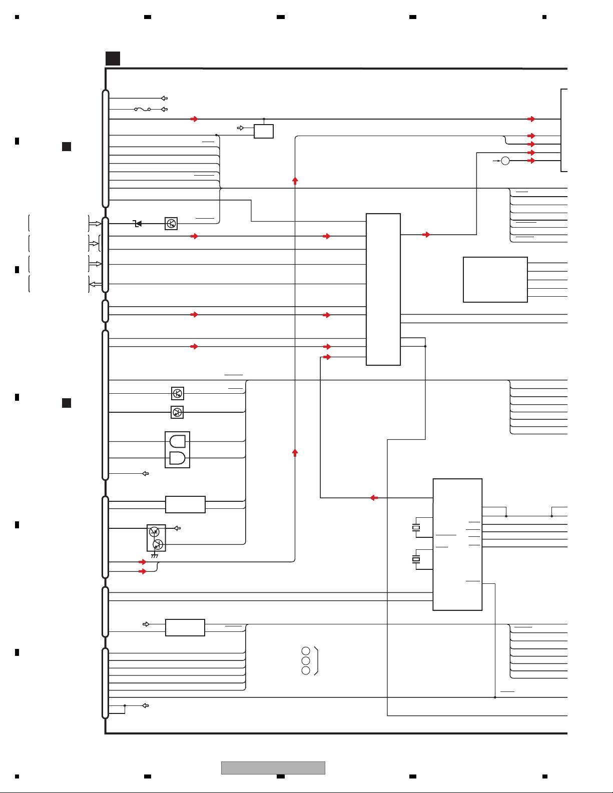
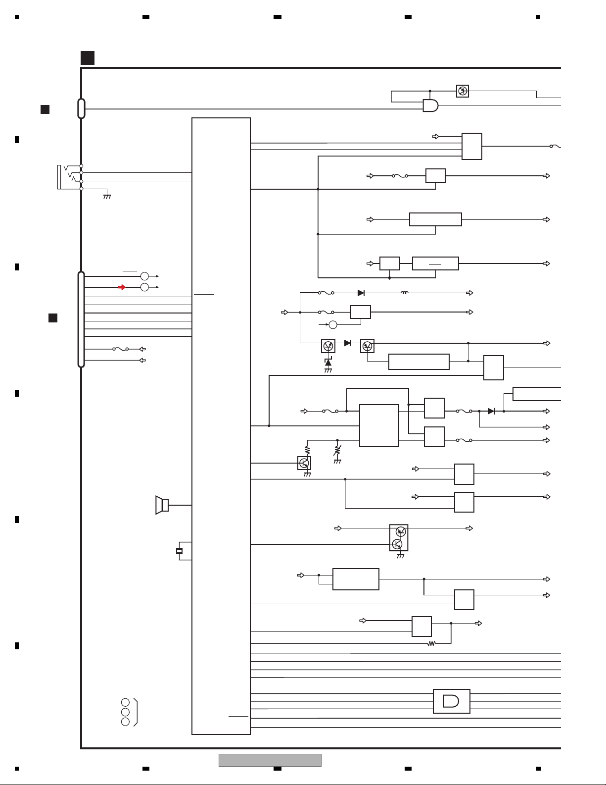
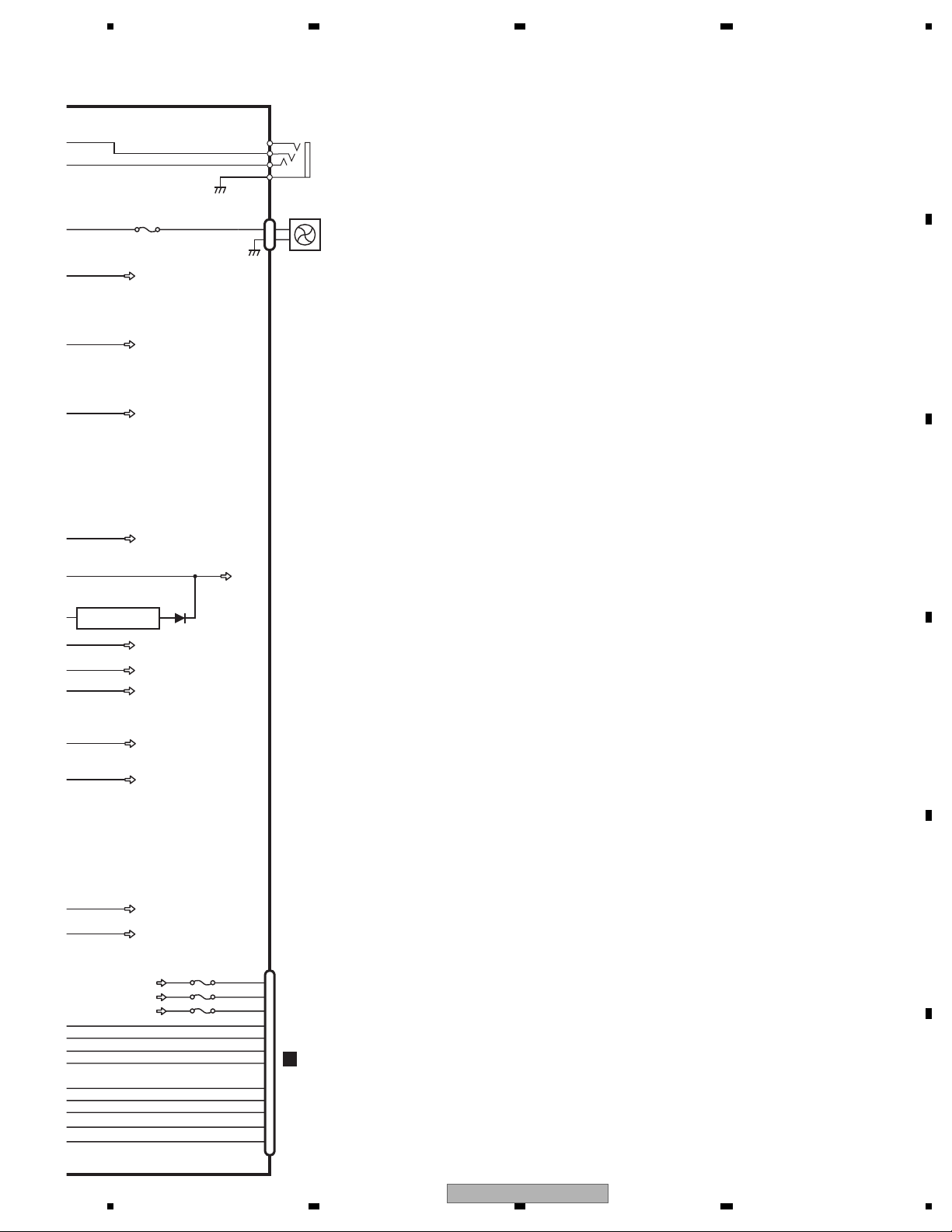
4.2 BLOCK DIAGRAM
DVD AMP UNIT (1/2)
A
A
B
REVERSE GEAR
SIGNAL IN
REAR VIEW
CAMMERA IN
RCA OUT
C
D
VCR IN
CN1901
MINI
JACK
CN801
1
VD
I
3
14
VDD5
I
17
LOUT
29
AMUTE
20
XRES
21
IRQPWR
22
→
MS5TX
S
23
MS5
24
STANBY
25
WAKEUP
40
COMPOSIT
32
CN121(1/2)
BG
20
VCR_L
10
VCR_V
14
B.CAMERA
15
REARVOUT
18
CN852
AUXV
1
AUXL
5
CN901
VOUT
7
LOUT
1
P801
→
SRX
VD8
VD5
BGSENS
Q141
AMUTE
XRES
IRQPW
S_MSTX
MS_SRX
STANDBY
WAKEUP
BGSENS
SYS+B
Q801
Q802
MS_V
VCR_L
VCR_V
BC_V
R_VOUT
AUX_V
AUX_L
IPOD_V
IPOD_L
USB_L
AV SELECTOR
IC301
AN15887A
37
V1-1
8
L2-1
39
V2-1
47
V6-1
32
VOUT2
45
V5-1
23
L5-1
43
V4-1
19
L4-1
15
L3-1
LOUT1
SDA
SCL
VOUT1
FB1
MS_L
BUSL+
BUSL-
LOUT
TUN_L
B
TO 2/2
AMUTE
XRES
IRQPW
S-MSTX
MS-SRX
28
IPOD CP
IC550
341S2304
35
36
34
33
STANDBY
WAKEUP
BGSENS
I2C_SCL
CP-READY
I2C_SDA
nRESET
XIN
7
IN
3
IN
4
IN
6
IN
5
IN
2
7
11
15
38
FLG
PSENSG
PSENS
PID
TXIPOD
RXIPOD
USB CONTROL
IC501
PE5661A
55
1
2
52
50
4
5
LOUT
USBXTAL1
USBXTAL2
XTAL2
XTAL1
DM
DP
BSCK
BRXEN
BSRQ
STBY
RESET
BSO
21
BSI
22
23
26
27
46
16
USBCNT
USBFLG
1
TXIE
RXIE
2
X502
48.000
ASENBO
1
USBCNT
EN
USBFLG
3
MHz
X501
A
B
TO 2/2
C
RESET
ACCDET
6
ACCPW
8
CN1901
B
D
IP-BUS
INPUT
E
10
11
12
14
1
5
8
7
11
2
3
ACCID
IPODTX
IPODRX
FMPWR
JA751
BUS+
BUS-
ABO
BUSL+
BUSL-
CN550
USBDM
USBDP
USB
ACC5
USB5V
1
CN601
DCK
2
FLMD0
5
DMS
6
DRST
FLASH WRITE
CONNECTOR
F
7
DDI
8
DDO
9
RESET
4
3.3V
10
11
Q903(1/2)
Q903(2/2)
IC701
TC7WH08FU
35
17
FMPW
IP-BUS DRIVER
IC751
HA12241FP
Q751
VDD33
6
5
4
5
DIN1
BUS+
ROUT
BUS-
BUP
USB5V
IC551
R5523N001B
VIN
VOUT
1
1
1
24
1234
AVH-P5150DVD/XN/RC
S_L
T
USL+
USL-
OUT
UN_L
7
IN1_L
3
IN4+_L
4
IN4-_L
6
IN2_L
5
IN5+_L
5 678
Q101(1/2)
Q101(2/2)
CN121(2/2)
FL
RL
2
RCA OUT
4
E.VOL CAPTAIN6
IC201
PML018A
Front_L
Rear_L
Pre/SW_L
DATA
CLK
STB
10
11
12
19
EVSDT
EVSCK
20
EVSTB
21
BUP
RCA_FL
RCA_RL
Q152
RCA MUTE
A
AMUTE
XRES
IRQPW
S-MSTX
MS-SRX
STANDBY
WAKEUP
BGSENS
XIN
_SCL
EADY
_SDA
ESET
USBCNT
USBFLG
66
AMUTE
63
XRESET
64
IRQPW
61
TXMS5
62
RXMS5
21
STNDBY
76
WAKEUP2
47
BGSENS
2
7
11
15
38
38
CPCLK
36
PCK
3
PRDY
35
PDT
4
PRST
22
AVSDATA
23
AVSCK
115
PSENSG
116
PSENS
132
PID
60
TXIPOD
59
RXIPOD
31
TXIE
32
RXIE
30
ASENBO
SYSTEM uCON
49
BSI
50
BSO
51
BSCK
54
BRXEN
53
BSRQ
48
BRST
94
USBCNT
95
USBFLG
41
DCK
8
FLMD0
42
DMS
20
DRST
39
DDI
40
DDO
IC601(1/2)
PE5673A
105
EVSDA
106
EVSCK
107
EVSEL
117
AMPPW
80
SYSMUTE
74
ASENS
75
BSENS
46
PBSENS
143
ISENS
82
TELMUTEIN
29
MONIRST
25
TXMON
26
RXMON
118
LEDCS
120
LEDCK
119
LEDDT
139 KEY1
KEYIN1
138 KEY2
KEYIN2
137 ROT1
ROTIN1
136 ROT2
ROTIN2
135
DSENS
14
RESET
BUP
EVSDT
EVSCK
EVSTB
SYS+B
OFFMUTE
Q155
Q153
ASENS
Q172(1/2)
BSENS
Q172(2/2)
PBSENS
Q171(1/2)
ISENS
Q173
TELMUTE
Q171(2/2)
MONITOR VBS BUFFER
Q351 Q352
TO 2/2
RESET
AMPMUTE
Q154
(1/2)
DAC
IC1551
M62343FP
8
LD
7
CLK
6
DI
A
RESET
1
IC602
S-80827CNNB-B8M
Q154
(2/2)
DSENS
AMP
IC151
VDD33
12
14
4
22
PAL007C
FLIN
RLIN
STBY
MUTE
B.REMOTE
BUP
TO 2/2
5
FL+
3
FL-
21
RL+
23
RL-
25
C
SWVDD33
Q1551
Q1552
Q1553
SWVDD33
PA_FL
PA_RL
1
A01
2
A02
3
A03
2
PWVI
PWFL
ILMB
CN171
FL+
FL-
RL+
RL-
B.REM
ACC
B.UP
P.B.
ILM
MUTE
CN441(1/2)
MONRST
S-MTX
M-SRX
MFLPWMFLPW
PWRVI
PWRFL
MONVBS
REM
CN851
REM
RED
GREEN
BLUE
DSENS
RESET
3
1
4
2
12
POWER
11
CONNECTOR
15
9
13
14
31
32
33
42
50
I
52
CN5001
G
39
.
40
35
I
37
58
46
7
1
2
3
6
CN3001
C
11
10
12
15
4
5
8
B
C
D
E
F
56
AVH-P5150DVD/XN/RC
7
8
25
A
8
5
V
C
C
V
D
B
S
5
B
C
D
E
F
D
WIRED
REMOTE
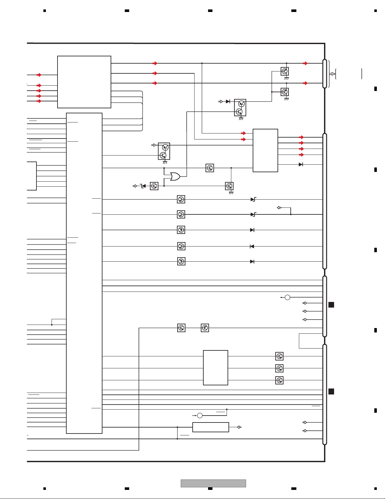
1234
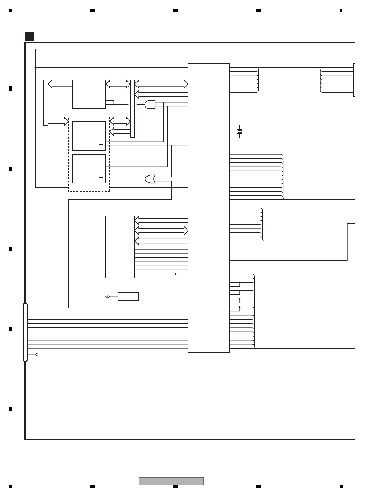
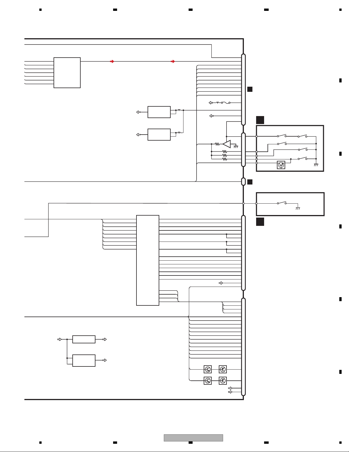
DVD AMP UNIT (2/2)
A
CN1852
JA2
I
1
4
14
6
19
13
15
11
17
16
20
CN951
OPTIN
JA431
2
3
WIRED
WIREDAD
4
1
GND
CN401
DSEN
TUN_L
TUNCE2
TUNCE
TUNDI
TUNDO
TUNCK
TUNSL
ROM_VDD
B.UP
P402
DSENS
A
B
C
A
B
BZ601
BUZZER
TO 1/2
TO 1/2
TO 1/2
VDD33
SWBUP
X601
4.718592MHz
140
WIRED
141
WIREDAD
114
TUNPCE2
113
TUNPCE
69
TUNPDO
68
TUNPDI
70
TUNPCK
144
TUNSL
56
BEEP
13
X2
12
X1
CLCNT1
CLCNT2
SYSPW
SYSTEM uCON
IC601(2/2)
PE5673A
ACCPW
DDCCTL
VDCONT
ILM_ON
SWVDD
PPOWER
VDSENS
ANGLE
LFTPULS
MTRPW
MTRSEL
DEGOSW
LEFSW
MTRS
MTR2
MTR1
5
1
2
IC951
TC7SET08FUS1
111
112
6
BUP
ACCPW
P1051
P1071
TO 1/2
Q1002
SYSPW
SYSPW
SYSPW
SYSPW
C
MFLPW
BUP
BUP
BUP
PWVI
PWFL
Q1071
Q1072
Q1001
Q1201
Q1202
2
BUP
P1151
SWBUP
Q1151
Q1152
SYS8.4V
IC1101
BA00CC0WFP
24
VCC
CTL
1
HIOUT 12V
IC1202
LT3461AES6
65
VIN
SHDN
4
VDD33V
IC1001
S-812C33AUA-C2N
DC/DC CONVERTER
OUT2
OUT1
ILMB
Q1522
4
5.4V REGULATOR
Q1402
7
Q1404
8V REGULATOR
Q1401
10
Q1403
5.4V
8V
FIREWIRE PW
Q1303
|
Q1305
TC74VHCT08AFTS1
23
1B
12 11
4A
98
3A
IC1401
BUP
7
ACCPW
55
65
78
37
133
131
129
17
124
122
126
125
123
127
24
Q1405
ACC5
P1403
VR1401
8V
BA00BC0WFP
1
VC
2
VIN
9
3
2
VDCNT
VDCNT
ACC33V
IC1601
BUP
AN8011S
VCC
ON/OFF
RT
VDD
4
VOUT
VOUT
3
P1401
P1402
VD5
Q1701
Q1702
Q1501
Q1502
SWVDD33V
Q1621
Q1622
IC441
VD8
1Y
4Y
3Y
Q951
FAN
Q1251
Q1254
|
PWVI
PWFL
Q1031
Q1032
ILMB
FWPW
2
S-1206B41-U3
USB33
IC1031
P12
SW
SY
EV1
VD
AC
5.4
8V
VD
VD
AC
SW
ACC5
ACC33
BUP
26
1234
AVH-P5150DVD/XN/RC
5 678
P1251
SWBUP
SYS+B
EV12
VDD33
JA951
OPTSENS
OPTOUT
OPTG
CN1251
FANB
A
2
3
4
1
2
1
DIGITAL OUT
REAR
FAN
B
C
2
S-1206B41-U3
USB33
IC1031
ACC5
ACC33
BUP
ACC5
5.4V
8V
VD5
VD8
ACC33
SWVDD33
USB33
3
D
E
CN441(2/2)
P442
SENPW
ANGLEIN
LIFTPUL
MTRS
MTRPW
MTR2
MTR1
MTRSEL
ANGLOSW
LETSW
VDD
10
11
18
I
20
1
2
3
CN101
J
4
5
6
7
8
9
F
P441
P443
56
AVH-P5150DVD/XN/RC
7
8
27
1234
O
P
DVD CORE UNIT
D
A
B
C
D
NRES
LATCH
IC1352
TC74LCX16373FT
A0-15
A0-15
12
FLASH 16M
CWW1763
CWW1764
RESET
IC1401
IC1402
AD0-15
48
1LE
25
2LE
AD0-15
A16-19
XCSSR26
CE
WE
WE
XWR111
XCSFM26
CE
TC7SZ32FU
11 XWR2
XRDNRES 28 50
OE
SDRAM
IC1481
EDS1232AATA-75-E
IC1403
AD0-15
A16-19
1
4
2
IC1351
TC7SZ08FU
1
4
2
MA0-11
MDQ0-31
DQM0-3
22
BA0
23 10
BA1
WE
CAS
RAS
20
CS
68
CLK
VOLTAGE DETECT
IC1003
S-80859CNNB-B9K
2 1 VSENS
CN1951
PR_A20 92
11
EXTRG1_SPD_SW
10
SCLOCK
9
SDATA
8
EXTRG0
7
TRCCLK
6
TRCD0
5
TRCD1
4
TRCD2
DEBUG
3
TRCD3
2
TRCST
1
12
VCC33
|
13
VD8
OUTVDD
XWE17 3
XCAS18 4
XRAS19 5
XCSM 6
MCK 234
XCSSR
XCSFM
VIDEO+AUDIO
MN2DS0016AAUB
101
NRST
77
XCSSR
51
NEXCE
62
NEXWE
NEXOE
8
BA0
BA1
NWE
NCAS
NRAS
NCSM
MCK
232
MCKI
88
VSENCE
P0
189
EXTRG1
192
SCLOCK
191
SDATA
190
EXTRG0
188
TRCCLK
187
TRCDATA0
186
TRCDATA1
185
TRCDATA2
184
TRCDATA3
183
TRCST
IC1501
SRCK
ADOUT3
LRCK
SDODAC
SCKDAC
LTDAC
DACCK
OSCO
OSCI
Comp
STANDBY
SLVSTS
HOSTCMD
IRQPWR
AMUTE
DSCSNS
PHOTOSNS
IECOUT
CONT2
CONT1
DRV3
DRV2
LOADIN
CLAMP
HOME
TEMP
VIN2RF
VIN2
VIN1RF
VIN1
VIN3RF
VIN3
VIN4RF
VIN4
VIN5
VIN6
CDMPD
DVDMPD
RFINN
F+H_G+H
E+G_E+F
LPCO2
LPCO1
174
175
173
91
90
74
172 DACCLK
169
170
152
Cr
153
Cb
154
Y
161
78
79
80
89
87
147
144
179
85
84
95
96
97
MD
93
99
FG
150
FD
149
TD
94
98
145
122
142
123
143
121
140
120
141
136
137
130
128
116
134
135
131
129
X1501
(CR)
(CB)
(COMPOSIT)
LDIN
B
A
C
D
FE1
FE2
RF
(Y)
COMPOSIT
STANBY
STSCOMN
CMDCOMN
AUDI
SRCK
ADOUT3
LRCK
SDODAC
SCKDAC
LTDAC
DACCLK
1
2
3
13
14
15
16
CR
CB
Y
E
VDD5
F
28
1234
AVH-P5150DVD/XN/RC
5 678
AUDIO 2CH ANALOG OUT
SRCK
ADOUT3
LRCK
SDODAC
SCKDAC
LTDAC
DACCLK
1
2
3
13
14
15
16
VDD5 VCC33
IC1801
PCM1753DBQ
VOUTL
BCK
DATA
LRCK
MD
MC
ML
SCK
NJM2885DL1-33
R1232D121B
2
VIN
3
VDD
7
3.3V REG.
IC1007
OUTIN
1.2V REG.
IC1008
A
CN1901
XRESETNRES
COMPOSIT
STANBY
SLVSTS
HSTCMD
IRQPWR
AMUTE
VD5
VD8
WAKE UP
CN1301
DiscDetect
1
2
8cm
8cm
12cm
PhotoPHOTOSNS
21
29
CR
38
CB
36
Y
34
32
25
24
23
CN801
A
22
20
14
|
17
3
2
|
1
40
3
2
4
5
1
COMPOUND UNIT(A)
E
S1203
DISC SENS
4
3
2
5
6
8cm
12cm
8cm
S1202
Q1299
S1204
S1201
S1205
B
VCC5
AVCC5
VCC5 REG.
IC1004
NJM2880U1-05
4
VOUT
AVCC5 REG.
IC1005
S-L2980A50MC-C7J
5
VOUT
CONT
ON/OFF
5
VIN
1
1
VIN
3
LOUT
STSCOMN
CMDCOMN
VDD5
VD8
DISC DET
IC1301
TC7SZ125FU
ANALOG LOUT
FU1901
4DSCSNS
CN1852
IECOUT
1
CN951
A
C
CLAMP1
MOTOR DRIVER
IC1201
BD7996EFV
CONT2
CONT1
DRV3
DRV2
MD
FD
TD
31
8
LX
VCC12
20 18
CTL2 SLO2-
21
CTL1
SLO1-
25
SLIN2
SLO2+
26
SLIN1
SLO1+
29
SPIN
LDIN
FG
ACTIN1
ACTIN2
HW-
HW+
HV-
HV+
HU-
HU+
ACO1ACO1+
ACO2+
ACO2-
V
W
U
HB
10
13
51
50
16
17
15
42
39
44
36
30
31
32
33
34
35
2
FOM
1
FOP
TOM
3
4
TOP
COILV
COILW
COILU
HBM
HWM
HWP
HVM
HVP
HUM
HUP
LPCO2
LPCO1
VDD5
HALL_BIAS-
HALL_BIAS+
Q1104Q1102
Q1103Q1101
VREF
VCC5
CN1201
COIL_V
COIL_W
COIL_U
HALL_W-
HALL_W+
HALL_V-
HALL_V+
HALL_U-
HALL_U+
SWITCHHOME
CN1101
FOM
FOP
TOM
TOP
78MDCDMPD
65MDDVDMPD
F+H/G+HF+H_G+H
E+G/E+FE+G_E+F
LD(CD)
LD(DVD)
VCC
FE1
FE2
B-
AB+
A+
FF+
TT+
THTEMP
B
A
C
D
RF
1
2
3
4
5
6
7
8
9
10
11
12
13
14
15
16
17
18
20
1
2
3
4
5
7
8
9
10
11
12
14
15
PU (DP8)
17
21
22
24
25
19
20
TP1
F
S1206
CLAMP
COMPOUND UNIT(B)
D
E
56
AVH-P5150DVD/XN/RC
F
7
8
29
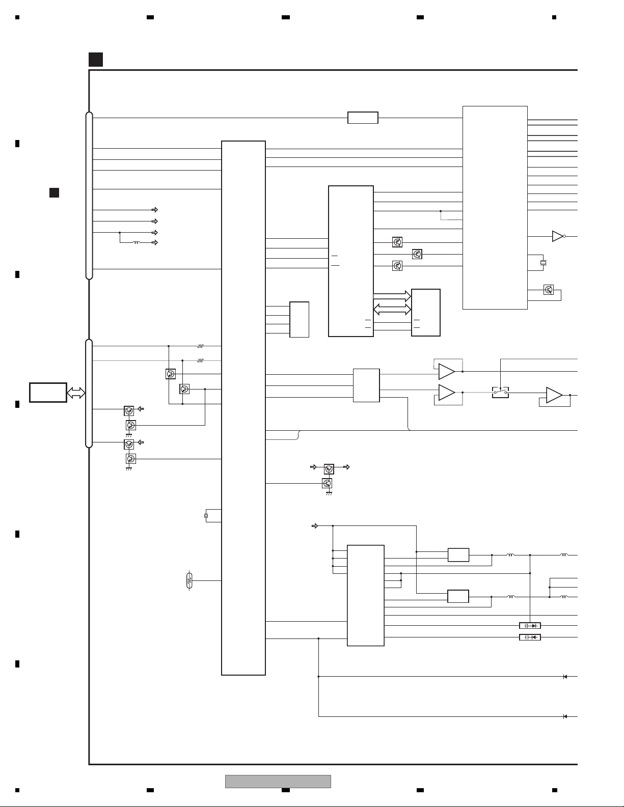
1234
B
MONITOR PCB
G
A
PICTURE SPLIT IC
IC5401
CN5001
MONVBS
28
S-MTX
8
M-SRX
9
REM
19
MFLPW
15
CN441
A
10
B
C
TOUCH
PANEL
D
I
12
13
.
14
21
I
23
7
4
3
1
2
MONRST
CN5002
PNLADY
PNLADX
PNLYV
PNLXV
Q5702
(1/2)
Q5701
(1/2)
Q5702
(2/2)
Q5701
(2/2)
Q5703
(1/2)
SWVDD33
SWVDD33
PWRFL
PWRVI
SWVDD33
SWD33
Q5703
(2/2)
MONITOR uCON
IC5603
PE5674A
36
DPDT1
35
KYDT1
48
REM
85
MFLPW
14
RESET
89
PNLADY
90
PNLADX
83
PNLVD
81
PNLYV
92
TOUCHAD
82
PNLXV
PIPCK
PIPDA
PIPRST
OSDSCL
OSDDATA
OSDCS
OSDRES
EPRDI
EPRDO
EPRCK
EPRCS
DACDI
DACCLK
DACLD
DIMMER
INVPUL
OSDPW
23
22
21
52
51
62
63
EEPROM
IC5604
S-93C56BD0I-J8
43
4
DO
3
44
DI
2
47
SK
45
1
CS
18
19
17
28
38
SWVDD33 OSD33V
61
5
6
7
15
Q5608
SCLK
SIN
CS
RST
Q5607
NJM2505AF
OSD IC
IC5802
PDC169B
6
7
8
14
IC5301
2
OSCin
9
VSYNC
11
HSYNC
30
BLK
34
ROUT
35
GOUT
Q5802(2/2)
36
BOUT
A[0-17]
D[0-11]
57
OE OE
58
IC5501
M62343FP
2
DILDA02
CLK
1
A01
3
A03
Q5801
INVBST
Q5802(1/2)
OSD ROM
PEH172A
28
26
CECE
IC5801
OSDR
OSDG
OSDB
2
3
5
6
+
+
-
66
Sub_C.
Video_IN1
104
Bus_Clock_IN
105
Bus_Data_IN
107
Reset_IN
91
OSD_Clock_Out
92
OSD_V.Sync_Out
93
OSD_C/H.Sync_Out
88
Main_RGB_Sync_IN1-2
101
OSD_Blank_High_IN
78
R_IN.2
79
G_IN.2
80
B_IN.2
1
IC5503
NJM2100V
7
TC90A96BFGSING
R[2-7]_D-Out
G[2-7]_D-Out
B[2-7]_D-Out
X'tal_OUT
DAC_Out
VCOM AMP
4
IC5505
TC7S66FU
STH
Load
CPH
CPV
STV
Vcom
X'tal_IN
PLL_IN
143-148
153-158
166-171
139
138
137
136
OE
135
134
133
53
52
60
56
IC5502
TC7SET04FUS1
42
X5401
42MHz
Q5401
IC5507
NJM082
521
7
+
6
-
13
100
12
XOUT
XIN
TEMPSEN
DDCON_SEL
MVIPW
PWRVI
30
80
D/D CONVERTER
IC5103
BD6171KV
11
PVCC1
6
PVCC2
41
PVCC
42
PVCC3
VCC
PVCC4
PVCC5
43
FIN
32
EN1
OUT2
OUT1
OUT3
OUT4
OUT5
8V REGULATOR
Q5103
4
S
7
4
VS2
23
48
37
10
13
VS1
22
47
38
3.3V REGULATOR
1,2,5,6
D
3
G
Q5102
4
S
1,2,5,6
D
3
G
CHARGE PUMP
REGULATOR
X5601
5MHz
TH5601
TEMP. SENSOR
E
F
30
1234
AVH-P5150DVD/XN/RC
 Loading...