


ë
POWER
ORDER NO.
RRV2033
STEREO AMPLIFIER
A-607R
THIS MANUAL IS APPLICABLE TO THE FOLLOWING MODEL(S) AND TYPE(S).
Type |
Model |
Power Requirement |
The voltage can be converted by the |
|
|
||||
A-607R |
following method. |
|||
|
|
|||
|
|
|
|
|
MV |
|
AC220 – 230V |
––––––– |
|
|
|
|
|
|
MY/EW |
|
AC220 – 230V |
––––––– |
|
|
|
|
|
|
MY/GR |
|
AC220 – 230V |
––––––– |
|
|
|
|
|
|
SD |
|
AC110V/120 – 127V/220/240V |
With the voltage selector |
|
|
|
|
|
CONTENTS
1. SAFETY INFORMATION ...................................... |
2 |
7. GENERAL INFORMATION |
................................ |
23 |
||||
|
|
|||||||
2. EXPLODED VIEWS AND PARTS LIST ................ |
3 |
7.1 IC INFORMATION |
....................................... |
23 |
||||
|
|
|
||||||
3. SCHEMATIC DIAGRAM ....................................... |
6 |
7.2 BLOCK DIAGRAM |
....................................... |
24 |
||||
|
|
|
||||||
4. PCB CONNECTION DIAGRAM .......................... |
14 |
8. PANEL FACILITIES AND SPECIFICATIONS |
.... |
25 |
||||
|
||||||||
5. PCB PARTS LIST |
............................................... |
19 |
|
|
|
|
|
|
|
|
|
|
|
|
|||
6. ADJUSTMENT |
.................................................... |
22 |
|
|
|
|
|
|
|
|
|
|
|
|
|
||
PIONEER ELECTRONIC CORPORATION 4-1, Meguro 1-Chome, Meguro-ku, Tokyo 153-8654, Japan PIONEER ELECTRONICS SERVICE, INC. P.O. Box 1760, Long Beach, CA 90801-1760, U.S.A.
PIONEER ELECTRONIC (EUROPE) N.V. Haven 1087, Keetberglaan 1, 9120 Melsele, Belgium
PIONEER ELECTRONICS ASIACENTRE PTE. LTD. 501 Orchard Road, #10-00 Wheelock Place, Singapore 238880
 PIONEER ELECTRONIC CORPORATION 1998
T – ZZK OCT. 1998 Printed in Japan
A-607R
1. SAFETY INFORMATION
This service manual is intended for qualified service technicians; it is not meant for the casual do-it-yourselfer. Qualified technicians have the necessary test equipment and tools, and have been trained to properly and safely repair complex products such as those covered by this manual.
Improperly performed repairs can adversely affect the safety and reliability of the product and may void the warranty. If you are not qualified to perform the repair of this product properly and safely, you should not risk trying to do so and refer the repair to a qualified service technician.
WARNING
This product contains lead in solder and certain electrical parts contain chemicals which are known to the state of California to
cause cancer, birth defects or other reproductive harm.
Health & Safety Code Section 25249.6 – Proposition 65
NOTICE
(FOR CANADIAN MODEL ONLY)
Fuse symbols  (fast operating fuse) and/or
  (slow operating fuse) on PCB indicate that replacement parts must be of identical designation.
REMARQUE
(POUR MODÈLE CANADIEN SEULEMENT)
Les symboles de fusible  (fusible de type rapide) et/ou
  (fusible de type lent) sur CCI indiquent que les pièces de remplacement doivent avoir la même désignation.
(FOR USA MODEL ONLY)
1. SAFETY PRECAUTIONS
The following check should be performed for the continued protection of the customer and service technician.
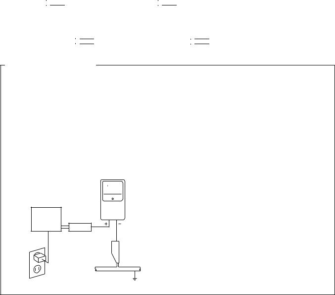
LEAKAGE CURRENT CHECK
Measure leakage current to a known earth ground (water pipe, conduit, etc.) by connecting a leakage c u r r e n t t e s t e r s u c h a s S i m p s o n M o d e l 2 2 9 - 2 o r equivalent between the earth ground and all exposed metal parts of the appliance (input/output terminals, screwheads, metal overlays, control shaft, etc.). Plug the AC line cord of the appliance directly into a 120V AC 60 Hz outlet and turn the AC power switch on. Any current measured must not exceed 0.5 mA.
|
|
Reading should |
|
Leakage |
not be above |
|
0.5 mA |
|
|
current |
|
|
|
|
Device |
tester |
|
under |
|
|
test |
|
|
Test all |
|
|
exposed metal |
|
|
surfaces |
|
|
Also test with |
|
|
plug reversed |
|
|
(Using AC adapter |
|
Earth |
plug as required) |
|
ground |
AC Leakage Test
ANY MEASUREMENTS NOT WITHIN THE LIMITS OUTLINED ABOVE ARE INDICATIVE OF A POTENTIAL SHOCK HAZARD AND MUST BE CORRECTED BEFORE RETURNING THE APPLIANCE TO THE CUSTOMER.
2. PRODUCT SAFETY NOTICE
Many electrical and mechanical parts in the appliance have special safety related characteristics. These are often not evident from visual inspection nor the protection afforded by them necessarily can be obtained by using replacement components rated for voltage, wattage, etc. Replacement parts which have these special safety characteristics are identified in this Service Manual.
Electrical components having such features are identified by marking with a  on the schematics and on the parts list in this Service Manual.
The use of a substitute replacement component which does not have the same safety characteristics as the PIONEER recommended replacement one, shown in the parts list in this Service Manual, may create shock, fire, or other hazards.
Product Safety is continuously under review and new instructions are issued from time to time. For the latest information, always consult the current PIONEER Service Manual. A subscription to, or additional copies of, PIONEER Service Manual may be obtained at a nominal charge from PIONEER.
2
A-607R
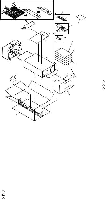
2. EXPLODED VIEWS AND PARTS LIST
∙
∙The  mark found on some component parts indicates the importance of the safety factor of the part. Therefore, when replacing, be sure to use parts of identical designation.
∙Screws adjacent to  mark on the product are used for disassembly.
2.1PACKINGParts marked by "NSP" are generally unavailable because they are not in our Master Spare Parts List.NOTES:
MV type Only
16 |
17 |
|
14 |
||
|
|
|
12 |
|
|
Separate |
|
|
13 |
8 |
|
FRONT |
|
10 |
|
|
|
(1) PACKING PARTS LIST
Except |
Mark No. |
Description |
|
Part No. |
|
MV type |
|
|
|
|
|
15 |
|
1 |
Operating Instructions |
See Contrast table (2) |
|
|
|
(English) |
|
||
|
|
2 |
Operating Instructions |
See Contrast table (2) |
|
5 |
4 (MY/EW, |
|
(German) |
|
|
3 |
Operating Instructions |
See Contrast table (2) |
|||
|
MY/GR and |
||||
|
|
(French/Italian/Dutch/Swedish/Spanish/Portugese) |
|||
6 |
MVtypes |
|
|||
|
|
|
|||
Only) |
|
|
|
||
|
|
|
|
||
7 1 (MV and MY/EW |
NSP |
4 |
Warranty Card |
See Contrast table (2) |
||
|
5 |
Remote Control Unit (CU-A018) AXD7187 |
||||
|
types Only) |
|
||||
|
|
6 |
Battery Cover |
AZN2249 |
||
|
2 (MY/EW and |
|
||||
|
NSP |
7 |
Dry Cell Battery (R6P,AA) |
AEX-010 |
||
|
MY/GR types |
|
8 |
Side Protector L |
AHA7127 |
|
|
Only) |
|
||||
|
|
|
|
|
||
|
3 (MY/EW |
|
9 |
Side Protector R |
AHA7128 |
|
|
type Only) |
|
10 |
Sub Pad |
AHA7245 |
|
|
18 (SD |
|
11 |
Packing Case |
See Contrast table (2) |
|
|
NSP |
12 |
Literature Bag |
AHG-117 |
||
Separate |
type Only) |
|||||
|
13 |
Packing Sheet |
AHG1016 |
|||
|
|
|||||
|
19 |
NSP |
14 |
Air Cap |
See Contrast table (2) |
|
|
(SD type |
|||||
|
|
15 |
Power Cord |
See Contrast table (2) |
||
|
Only) |
|
||||
|
|
16 |
Power Cord with Fuse |
See Contrast table (2) |
||
|
|
|
||||
|
|
|
17 |
Fuse (T5A) |
See Contrast table (2) |
|
|
|
|
18 |
Operating Instructions |
See Contrast table (2) |
|
9 |
|
|
|
(Spanish/Chinese) |
|
|
|
|
NSP |
19 |
Caution Label 220V |
See Contrast table (2) |
|
11
(2) CONTRAST TABLE
A-607R/MV, MY/EW, MY/GR and SD types are constructed the same except for the following :
Mark |
No. |
Symbol and Description |
|
Part No. |
|
Remarks |
||
|
|
|
|
|||||
MV Type |
MY/EW Type |
MY/GR Type |
SD Type |
|||||
|
|
|
|
|||||
|
|
|
|
|
|
|
|
|
|
1 |
Operating Instructions (English) |
ARB7161 |
ARB7161 |
Not used |
Not used |
|
|
|
2 |
Operating Instructions (German) |
Not used |
ARC7211 |
ARC7211 |
Not used |
|
|
|
3 |
Operating Instructions |
Not used |
ARC7212 |
Not used |
Not used |
|
|
|
|
(French/Italian/Dutch/Swedish/Spanish/Portuguese) |
|
|
|
|
|
|
|
4 |
Warranty Card |
ARY7022 |
ARY7022 |
ARY7022 |
Not used |
|
|
|
11 |
Packing Case |
AHD7653 |
AHD7653 |
AHD7653 |
AHD7675 |
|
|
NSP |
14 |
Air Cap |
AHG1087 |
Not used |
Not used |
Not used |
|
|
|
15 |
Power Cord |
Not used |
ADG1154 |
ADG1154 |
ADG1158 |
|
|
|
16 |
Power Cord with Fuse |
ADG1156 |
Not used |
Not used |
Not used |
|
|
|
17 |
Fuse (T5A) |
AEK1046 |
Not used |
Not used |
Not used |
|
|
|
18 |
Operating Instructions (Spanish/Chinese) |
Not used |
Not used |
Not used |
ARC7210 |
|
|
NSP |
19 |
Caution Label 220V |
Not used |
Not used |
Not used |
ARR7003 |
|
|
|
|
|
|
|
|
|
|
|
3

A-607R
2.2 EXTERIOR
|
48 |
44 |
|
|
|
|
|
|
|
|
|
|
3 |
44 |
|
|
|
|
|
|
|
43 |
|
|
|
|
|
34 |
|
37 |
|
|
|
5 |
|
|
|
|
|
28 |
|
|
|
|
18 |
|
|
|
|
|
|
41 |
|
10 |
|
|
|
16 |
|
38 |
|
|
10 |
|
|
|
47 |
|
|
|
|
|
49 |
|
30 |
|
|
|
41 |
|
|
|
|
27 |
|
|
|
|
27 |
35 |
|
|
|
|
31 |
16 |
|
|
|
|
16 |
|
|
|
|
|
|
|
|
|
|
31 |
32 |
|
|
|
57 |
42 |
|
33 |
|
|
|
|
|
|
|
|
60 |
|
|
|
|
53 |
|
|
|
|
|
|
42 |
|
|
|
|
|
|
39 |
|
|
|
|
|
|
|
|
|
|
36 |
|
|
|
|
|
|
42 |
|
56 |
|
|
|
|
|
|
|
|
|
|
|
|
|
|
|
|
|
|
|
|
42 |
|
39 |
|
|
|
|
|
|
|
|
|
|
|
|
|
|
|
39 |
|
|
|
|
|
|
|
44 |
|
|
|
|
|
|
|
|
|
(SD Type Only) 64 |
8 |
|
|
|
|
|
||
|
(Except MV Type) 65 |
|
|
|
|
|
||||
|
|
|
|
|
|
|
||||
|
|
|
|
15 |
|
|
|
|
|
|
|
|
16 |
|
|
|
|
|
39 |
|
|
|
|
|
|
|
|
|
|
|
|
|
|
|
19 |
|
|
|
|
59 |
59 |
26 |
|
|
|
|
|
|
|
|
|
|||
|
|
|
|
|
|
|
|
|
||
|
|
|
|
|
4 |
|
|
|
24 |
|
|
|
|
|
|
26 |
|
|
|
15 |
|
44 |
43 |
|
|
|
|
15 |
|
|
|
|
6 |
|
|
24 |
|
|
|
|
|||
|
|
|
|
|
|
|
||||
|
|
26 |
|
45 |
|
|
|
|
||
|
|
|
|
|
|
|
|
|||
|
|
|
|
|
|
|
|
|
||
1 |
|
|
|
|
15 |
|
|
|
|
|
|
|
|
|
45 |
|
|
|
|
|
|
|
|
|
|
|
|
15 |
|
|
45 |
|
|
|
|
|
|
|
|
|
|
15 |
|
|
|
2 |
|
|
|
15 |
|
45 |
|
|
|
|
|
|
|
|
45 |
|
|
||
|
|
|
|
|
|
|
|
|
||
|
|
|
|
|
|
7 |
|
|
|
|
|
|
|
|
|
|
(Except MV Type) |
|
|
||
|
9 |
17 |
|
|
|
13 |
|
51 |
(SD Type Only) |
|
|
|
45 |
|
|
20 |
|
62 |
|||
|
43 |
|
|
|
|
|
|
|||
|
17 |
|
|
|
|
|
|
|||
|
17 |
|
|
|
42 |
|
|
|
||
|
|
|
|
|
|
|
|
|||
|
|
|
|
|
|
|
|
|
|
|
|
|
|
|
|
|
|
|
42 |
42 42 |
|
|
|
|
11 |
|
|
|
|
|
|
|
29 |
|
|
|
23 |
23 |
|
|
|
42 |
40 |
|
|
|
63 |
|
|
|
|
|||
|
|
|
|
|
|
|
|
|
|
|
|
61 |
|
|
|
|
23 |
|
|
|
|
|
|
58 |
|
|
|
|
|
|
|
|
|
(Except |
|
|
|
23 |
|
|
|
||
46 |
|
|
|
|
|
|
50 |
|||
SD Type) |
|
|
|
|
|
|
||||
|
|
|
|
|
|
|
||||
|
12 |
|
|
|
|
|
|
|
|
|
|
|
|
|
|
|
|
|
|
23 |
|
54 54 |
|
|
22 |
|
|
|
|
|
|
|
|
|
14 |
|
|
|
|
|
|
58 |
|
|
|
55 |
|
|
|
|
|
14 |
|
|
|
54 |
52 |
|
|
|
|
|
|
||
|
|
21 |
|
|
|
|
|
|
||
|
|
|
|
|
|
|
|
|
|
|
|
|
26 |
|
21 |
|
|
|
52 |
|
|
|
|
|
|
|
25 |
|
|
|
|
|
|
|
|
|
|
|
|
26 |
|
|
|
|
|
|
|
|
|
|
|
|
|
|
4
A-607R
(1) EXTERIOR PARTS LIST
Mark |
No. |
Description |
|
Part No. |
Mark |
No. |
Description |
|
Part No. |
|
1 |
FRONT L Assy |
AWX7054 |
|
31 |
Rotary Knob A |
|
AAB7148 |
|
|
2 |
FRONT R Assy |
AWX7146 |
|
32 |
Rotary Knob B |
|
AAB7149 |
|
|
3 |
POWER SW Assy |
See Contrast table (2) |
|
33 |
Volume Knob |
|
AAB7189 |
|
|
4 |
AC PRIMARY Assy |
See Contrast table (2) |
|
34 |
Speaker Button |
|
AAD7435 |
|
NSP |
5 |
HEADPHONE Assy |
AWX7052 |
|
35 |
Main Power Button |
|
See Contrast table (2) |
|
|
6 |
VOLUME Assy |
AWX7171 |
|
36 |
Bonnet Case |
|
ANE7220 |
|
|
7 |
AF Assy |
AWX7200 |
|
37 |
Panel Base |
|
See Contrast table (2) |
|
|
8 |
Fuse (FU1, T2A L250V) |
AEK1057 |
|
38 |
Front Panel |
|
See Contrast table (2) |
|
|
9 |
Flexible Cable (J1, 21P) |
ADD1114 |
|
39 |
Screw |
|
BBT30P080FZK |
|
|
|
(AF CN202 - FRONT R CN601) |
|
|
40 |
Terminal Screw |
|
AKE-031 |
|
|
10 |
Washer |
ABE1002 |
|
41 |
Nut |
|
NK90FUC |
|
|
|
|
|
|
|
|
|||
|
11 |
Power Transformer (T1) |
See Contrast table (2) |
|
42 |
Screw |
|
ABA1006 |
|
NSP |
12 |
Chassis |
ANA7048 |
|
43 |
Screw |
|
ABA1009 |
|
|
13 |
Rear Panel |
See Contrast table (2) |
|
44 |
Screw |
|
BPZ30P080FMC |
|
|
14 |
Insulator |
PNW2766 |
|
45 |
Washer |
|
WG40FCC |
|
|
15 |
Screw |
ABA1018 |
|
46 |
LED Lens B |
|
AAK7538 |
|
|
|
|
|
|
|
|
|||
|
16 |
Screw |
ABA1050 |
|
47 |
LED Lens |
|
PNW2019 |
|
|
17 |
Screw (4 × 10) |
See Contrast table (2) |
|
48 |
Power Button |
|
AAD7436 |
|
|
18 |
Nut |
ABN-065 |
|
49 |
Screw |
|
BMZ30P080FCU |
|
NSP |
19 |
PCB Mold |
AMR7222 |
|
50 |
Short Pin Plug |
|
AKM-050 |
|
|
20 |
Barrier |
AEC7072 |
|
51 |
AC Outlet 3-P |
|
See Contrast table (2) |
|
|
|
|
|
|
|
|
|||
NSP |
21 |
PCB Holder |
AEC7057 |
|
52 |
Cushion 55 |
|
PNM1316 |
|
|
22 |
Stud Cover |
AEC7096 |
|
53 |
Screw |
|
ABA1193 |
|
NSP |
23 |
PCB Mold |
AMR1525 |
|
54 |
Spacer |
|
ABF7004 |
|
NSP |
24 |
Radiator Plate A |
AMR7221 |
|
55 |
Stud Cover |
|
AEC7105 |
|
|
25 |
Locking Card Spacer |
DEC1908 |
|
56 |
Top Cover |
|
AME1086 |
|
|
|
|
|
|
|
|
|||
|
26 |
Screw |
ABA-298 |
|
57 |
Dump Plate |
|
ANG7198 |
|
|
27 |
LED Lens |
AAK2459 |
|
58 |
Cushion Gum |
|
AEB7004 |
|
|
28 |
IR Filter |
AAK7532 |
NSP |
59 |
Radiator Plate C |
|
AMR7257 |
|
|
29 |
LED Lens T |
AAK7544 |
NSP |
60 |
Sub Frame |
|
ANG7137 |
|
|
30 |
Name Plate |
PAN1376 |
|
61 |
Trans Plate |
|
See Contrast table (2) |
|
|
|
|
|
|
|
|
|||
|
|
|
|
|
|
62 |
Voltage Selector (S1) |
|
See Contrast table (2) |
|
|
|
|
|
|
63 |
Voltage Selector (S2) |
|
See Contrast table (2) |
|
|
|
|
|
|
64 |
Fuse (FU2 : T2A) |
|
See Contrast table (2) |
|
|
|
|
|
|
65 |
Fuse (FU3 : T0.5A) |
|
See Contrast table (2) |
(2) CONTRAST TABLE
A-607R/MV, MY/EW, MY/GR and SD types are constructed the same except for the following :
Mark |
No. |
Symbol and Description |
|
Part No. |
|
Remarks |
||
|
|
|
|
|||||
MV Type |
MY/EW Type |
MY/GR Type |
SD Type |
|||||
|
|
|
|
|||||
|
|
|
|
|
|
|
|
|
|
3 |
POWER SW ASSY |
AWX7057 |
AWX7057 |
AWX7057 |
Not used |
|
|
|
4 |
AC PRIMARY Assy |
AWX7056 |
AWX7197 |
AWX7197 |
AWX7198 |
|
|
|
11 |
Power Transformer (T1 : AC220-230V) |
ATS7128 |
ATS7128 |
ATS7128 |
Not used |
|
|
|
11 |
Power Transformer |
Not used |
Not used |
Not used |
ATS7129 |
|
|
|
|
(T1 : AC110V/120-127V/220V/240V) |
|
|
|
|
|
|
|
13 |
Rear Panel |
ANC7726 |
ANC7725 |
ANC7725 |
ANC7727 |
|
|
|
17 |
Screw |
ABA1014 |
ABA1014 |
ABA1014 |
ABA7047 |
|
|
|
35 |
Main Power Button |
ADD7437 |
ADD7437 |
ADD7437 |
Not used |
|
|
|
37 |
Panel Base |
AMB7484 |
AMB7484 |
AMB7484 |
AMB7553 |
|
|
|
38 |
Front Panel |
ANB7149 |
ANB7149 |
ANB7149 |
ANB7152 |
|
|
|
51 |
AC Outlet 3-P |
Not used |
AKP-502 |
AKP-502 |
AKP7007 |
|
|
|
61 |
Trans Plate |
ANG7228 |
ANG7228 |
ANG7228 |
Not used |
|
|
|
62 |
Voltage Selector (S1) |
Not used |
Not used |
Not used |
AKX-507 |
|
|
|
63 |
Voltage Selector (S2) |
Not used |
Not used |
Not used |
AKX1004 |
|
|
|
64 |
Fuse (FU2 : T2A) |
Not used |
Not used |
Not used |
AEK1057 |
|
|
|
65 |
Fuse (FU3 : T0.5A) |
Not used |
AEK1051 |
AEK1051 |
AEK1051 |
|
|
|
|
|
|
|
|
|
|
|
5
|
1 |
|
2 |
|
3 |
|
4 |
|
|
|
|
|
|
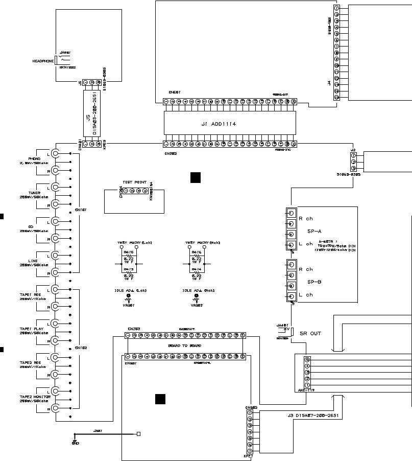
A-607R
3. SCHEMATIC DIAGRAM
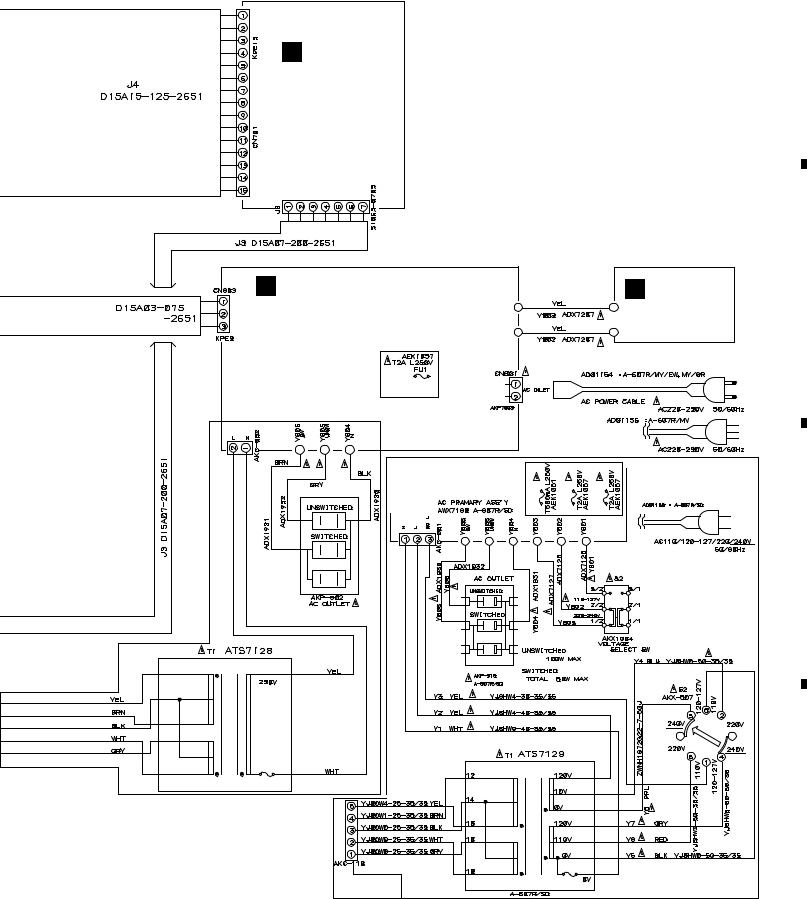
3.1 OVERALL CONNECTION DIAGRAM
A |
F |
HEADPHONE |
|
|
|
|
|
|
|
||
|
|
D |
FRONT R ASSY |
||
|
|
|
ASSY |
||
|
|
|
(AWX7052) |
|
(AWX7146) |
|
|
|
|
|
|
|
|
|
|
|
|
B
A AF ASSY (AWX7200)
C
C VOLUME ASSY
(AWX7171)
D
6
|
1 |
|
2 |
|
3 |
|
4 |
|
|
|
|
|
|
||||
|
|
|
|
|
|
5 |
|
6 |
|
7 |
|
8 |
|
|
|
|
|
|
A-607R
Note : When ordering service parts, be sure to refer to "EXPLODED VIEWS and PARTS LIST" or "PCB PARTS LIST".
B FRONT L ASSY (AWX7054)
E AC PRIMARY ASSY (MY/EW, MY/GR : AWX7197) (MV : AWX7056)
(SD : AWX7198)
(MY/EW, MY/GR ONLY)
AC PRIMARY ASSY (SD ONLY)
A
EXCEPT SD TYPE |
|
G POWER SW |
B |
ASSY |
|
(AWX7057) |
|
C
D
7
|
5 |
|
6 |
|
7 |
|
8 |
|
|
|
|
|
|
||||
|
|
|
|
|
1 |
2 |
3 |
4 |
A-607R |
|
|
|
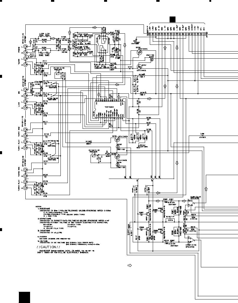
3.2 AF ASSY |
|
|
C CN501 |
A |
|
|
|
B |
|
|
|
C |
|
|
|
: AUDIO SIGNAL ROUTE
D
8 A
|
1 |
|
2 |
|
3 |
|
4 |
|
|
|
|
|
|
||||
|
|
|
|
|

|
5 |
|
6 |
|
7 |
|
8 |
|
|
|
|
A-607R
D CN601 |
E CN803 |
|
A AF ASSY (AWX7200)


 POWERTO


 T1TRANSFORMER
L406
ATX1012
F J5 |
A 9 |
|
A
B
C
D
|
5 |
|
6 |
|
7 |
|
8 |
|
|
|
|
|
|
||||
|
|
|
|
|
 Loading...