


 Loading...
Pioneer 3™
&
Pioneer 2™
H8-Series
Operations Manual
Copyright © 2003, ActivMedia Robotics, LLC. All rights reserved.
Under international copyright laws, this manual or any portion of it may not be copied or in any way duplicated without the expressed written consent of ActivMedia Robotics.
The software on disk, CD-ROM, and/or in the microcontroller’s FLASH, which accompany the robot and are available for network download by ActivMedia Robotics customers, are solely owned and copyrighted or are licensed products distributed by ActivMedia Robotics, LLC.
Developers and users are authorized by revocable license to develop and operate custom software for personal research and educational use only. Duplication, distribution, reverse-engineering, or commercial application of the ActivMedia Robotics software and hardware without the expressed written consent of ActivMedia Robotics, LLC, is explicitly forbidden.
The various names and logos for products used in this manual are often registered trademarks or trademarks of their respective companies. Mention of any third-party hardware or software constitutes neither an endorsement nor a recommendation.
Pioneer 3 & Pioneer 2 H8-Series Operations Manual, version 3, August 2003
ii
ActivMedia Robotics
Important Safety Instructions
Read the installation and operations instructions before using the equipment. Avoid using power extension cords.
To prevent fire or shock hazard, do not expose the equipment to rain or moisture. Refrain from opening the unit or any of its accessories.
Keep wheels away from long hair or fur.
Never access the interior of the robot with charger attached or batteries inserted.
Inappropriate Operation
Inappropriate operation voids your warranty! Inappropriate operation includes, but is not limited to:
Dropping the robot, running it off a ledge, or otherwise operating it in an irresponsible manner
Overloading the robot above its payload capacity Getting the robot wet
Continuing to run the robot after hair, yarn, string, or any other items have become wound around the robot’s axles or wheels
Opening the robot with charger attached and/or batteries inserted All other forms of inappropriate operation or care
iii
Table of Contents |
|
CHAPTER 1 INTRODUCTION................................................................................................................. |
1 |
ROBOT PACKAGE ........................................................................................................................................ |
1 |
Basic Components (all shipments).......................................................................................................... |
1 |
Optional Components and Attachments (partial list) ............................................................................. |
1 |
User-Supplied Components / System Requirements ............................................................................... |
2 |
ADDITIONAL RESOURCES ............................................................................................................................ |
2 |
Support Website...................................................................................................................................... |
2 |
Newsgroups ............................................................................................................................................ |
2 |
Support ................................................................................................................................................... |
3 |
CHAPTER 2 WHAT IS PIONEER? .......................................................................................................... |
4 |
PIONEER REFERENCE PLATFORM ................................................................................................................ |
4 |
PIONEER FAMILY OF MICROCONTROLLERS AND OPERATING SYSTEM SOFTWARE ...................................... |
4 |
HITACHI H8S-BASED MICROCONTROLLER .................................................................................................. |
5 |
PLUS MOTOR-POWER BOARD ..................................................................................................................... |
5 |
CLIENT SOFTWARE...................................................................................................................................... |
6 |
ARIA ....................................................................................................................................................... |
6 |
Saphira ................................................................................................................................................... |
7 |
Laser Navigation and Localization......................................................................................................... |
7 |
SUPPORTING SOFTWARE.............................................................................................................................. |
7 |
Simulator ................................................................................................................................................ |
7 |
Mapper ................................................................................................................................................... |
7 |
THE PIONEER LEGACY................................................................................................................................. |
7 |
Pioneer 1 and AT.................................................................................................................................... |
8 |
Pioneer 2 and PeopleBot ........................................................................................................................ |
8 |
New Pioneer 3 and Recent Pioneer 2-DX8, -AT8, and Plus Mobile Robots .......................................... |
9 |
MODES OF OPERATION .............................................................................................................................. |
10 |
Server Mode.......................................................................................................................................... |
10 |
Maintenance and Standalone Modes.................................................................................................... |
10 |
Joydrive and Self Test Modes ............................................................................................................... |
10 |
CHAPTER 3 SPECIFICATIONS & CONTROLS ................................................................................. |
11 |
PHYSICAL CHARACTERISTICS.................................................................................................................... |
11 |
MAIN COMPONENTS .................................................................................................................................. |
12 |
Motor Stop Button ................................................................................................................................ |
12 |
User Control Panel............................................................................................................................... |
13 |
Body, Nose, and Accessory Panels ....................................................................................................... |
14 |
Sonar Arrays with Gain Adjustment ..................................................................................................... |
14 |
Motors, Wheels, and Position Encoders............................................................................................... |
15 |
BATTERIES AND POWER ............................................................................................................................ |
15 |
Battery Indicators and Low Voltage Conditions................................................................................... |
16 |
Recharging ........................................................................................................................................... |
16 |
DOCKING/CHARGING SYSTEM................................................................................................................... |
17 |
Manual Operation (Robot Power OFF) ............................................................................................... |
17 |
Manual Operation (Robot Power and Systems ON)............................................................................. |
17 |
RADIO CONTROLS AND ACCESSORIES ....................................................................................................... |
18 |
ONBOARD PC ............................................................................................................................................ |
19 |
Computer Control Panel....................................................................................................................... |
19 |
Operating the Onboard PC .................................................................................................................. |
20 |
PC Networking ..................................................................................................................................... |
20 |
UPS and Genpower .............................................................................................................................. |
21 |
SAFETY AROS WATCHDOGS .................................................................................................................... |
22 |
CHAPTER 4 QUICK START................................................................................................................... |
23 |
PREPARATIVE ASSEMBLY.......................................................................................................................... |
23 |
Install ARIA .......................................................................................................................................... |
23 |
Install Batteries..................................................................................................................................... |
24 |
Client-Server Communications............................................................................................................. |
24 |
iv
|
ActivMedia Robotics |
STARTING UP CLIENT AND SERVER ........................................................................................................... |
24 |
Drive Self-Test....................................................................................................................................... |
24 |
Client Server Connection ...................................................................................................................... |
24 |
Demo Startup Options ........................................................................................................................... |
25 |
A Successful Connection ....................................................................................................................... |
26 |
OPERATING THE ARIA DEMONSTRATION CLIENT ..................................................................................... |
26 |
DISCONNECTING ........................................................................................................................................ |
27 |
QUICKSTART TROUBLESHOOTING.............................................................................................................. |
27 |
Proper Connections............................................................................................................................... |
27 |
SRIsim ................................................................................................................................................... |
28 |
CHAPTER 5 JOYDRIVE AND SELF-TESTS ........................................................................................ |
29 |
JOYDRIVE MODE ........................................................................................................................................ |
29 |
ENGAGING SELF-TESTS.............................................................................................................................. |
30 |
CHAPTER 6 ACTIVMEDIA ROBOTICS OPERATING SYSTEM..................................................... |
31 |
CLIENT-SERVER COMMUNICATION PACKET PROTOCOLS........................................................................... |
31 |
Packet Checksum................................................................................................................................... |
32 |
Packet Errors ........................................................................................................................................ |
32 |
SERVER INFORMATION PACKETS ............................................................................................................... |
33 |
CLIENT COMMANDS................................................................................................................................... |
34 |
THE CLIENT-SERVER CONNECTION............................................................................................................ |
36 |
Autoconfiguration (SYNC2)................................................................................................................... |
37 |
Opening the Servers—OPEN ................................................................................................................ |
37 |
Keeping the Beat—PULSE.................................................................................................................... |
37 |
Closing the Connection—CLOSE.......................................................................................................... |
37 |
MOTION COMMANDS ................................................................................................................................. |
38 |
ActivMedia Robots in Motion................................................................................................................ |
39 |
Platform Dependent and Independent Variables .................................................................................. |
39 |
PID Controls ......................................................................................................................................... |
40 |
Position Integration............................................................................................................................... |
41 |
SONAR ....................................................................................................................................................... |
41 |
Enable/Disabling Sonar ........................................................................................................................ |
41 |
Polling Sequence and Rate.................................................................................................................... |
41 |
STALLS AND EMERGENCIES ........................................................................................................................ |
42 |
ACCESSORY COMMANDS AND PACKETS .................................................................................................... |
43 |
Packet Processing ................................................................................................................................. |
43 |
CONFIGpac and CONFIG Command .................................................................................................. |
44 |
SERIAL PORT COMMUNICATIONS ................................................................................................................ |
44 |
Changing Baud Rates and Autobauding ............................................................................................... |
44 |
HOST-to-AUX Serial Transfers............................................................................................................. |
45 |
ENCODER PACKETS .................................................................................................................................... |
45 |
Gripper packets ..................................................................................................................................... |
45 |
Sounds ................................................................................................................................................... |
46 |
TCM2..................................................................................................................................................... |
46 |
Onboard PC .......................................................................................................................................... |
47 |
Heading Correction Gyro...................................................................................................................... |
47 |
INPUT OUTPUT (I/O) .................................................................................................................................. |
48 |
User I/O................................................................................................................................................. |
48 |
Bumper and IR I/O ................................................................................................................................ |
49 |
IO packets.............................................................................................................................................. |
49 |
Expansion I/O........................................................................................................................................ |
50 |
DOCKING/CHARGING SYSTEM I/O ............................................................................................................. |
50 |
Digital Port Controls............................................................................................................................. |
50 |
Docking/Charging Servers .................................................................................................................... |
50 |
Monitoring the Recharge Cycle............................................................................................................. |
51 |
CHAPTER 7 UPDATING & RECONFIGURING AROS ...................................................................... |
53 |
WHERE TO GET AROS SOFTWARE ............................................................................................................ |
53 |
AROS MAINTENANCE MODE .................................................................................................................... |
53 |
SIMPLE AROS UPDATES............................................................................................................................ |
53 |
v
AROSCF ................................................................................................................................................... |
54 |
STARTING AROSCF................................................................................................................................... |
54 |
CONFIGURING AROS OPERATING PARAMETERS ...................................................................................... |
55 |
Interactive Commands.......................................................................................................................... |
55 |
Changing Parameters........................................................................................................................... |
55 |
SAVE YOUR WORK.................................................................................................................................... |
56 |
PID PARAMETERS ..................................................................................................................................... |
56 |
TICKSMM AND REVCOUNT ........................................................................................................................ |
58 |
STALLVAL AND STALLCOUNT .................................................................................................................. |
59 |
BUMPERS................................................................................................................................................... |
59 |
CHAPTER 8 MAINTENANCE & REPAIR............................................................................................ |
61 |
TIRE INFLATION ........................................................................................................................................ |
61 |
DRIVE LUBRICATION ................................................................................................................................. |
61 |
BATTERIES ................................................................................................................................................ |
61 |
Changing Batteries ............................................................................................................................... |
61 |
Hot-Swapping the Batteries.................................................................................................................. |
61 |
Charging the Batteries.......................................................................................................................... |
61 |
Automated Docking/Charging System .................................................................................................. |
62 |
Alternative Battery Chargers................................................................................................................ |
62 |
TIGHTENING THE AT DRIVE BELT............................................................................................................. |
62 |
GETTING INSIDE ........................................................................................................................................ |
63 |
Removing the Nose ............................................................................................................................... |
63 |
Opening the Deck ................................................................................................................................. |
64 |
FACTORY REPAIRS .................................................................................................................................... |
64 |
APPENDIX A.............................................................................................................................................. |
65 |
H8S PORTS & CONNECTIONS.................................................................................................................... |
65 |
H8S MICROCONTROLLER.......................................................................................................................... |
65 |
Power Connector.................................................................................................................................. |
65 |
Serial Ports........................................................................................................................................... |
66 |
User I/O, Gripper, Docking/Charging Port ......................................................................................... |
66 |
The Expansion I/O Bus ......................................................................................................................... |
67 |
Bumper Ports........................................................................................................................................ |
68 |
Motors, Encoders, and IR Sensors........................................................................................................ |
68 |
User Control Interface.......................................................................................................................... |
68 |
Joystick Port ......................................................................................................................................... |
69 |
APPENDIX B.............................................................................................................................................. |
70 |
PIONEER 3 AND 2-PLUS MOTOR-POWER BOARD ....................................................................................... |
70 |
Configuration for Current and Temperature Sensing........................................................................... |
70 |
Controller Power and Interface............................................................................................................ |
71 |
Radio, Auxiliary, and User Power Connectors .................................................................................... |
71 |
IR Signal and Power............................................................................................................................. |
72 |
LEGACY MOTOR-POWER........................................................................................................................... |
72 |
APPENDIX C.............................................................................................................................................. |
73 |
RADIO MODEM SETTINGS.......................................................................................................................... |
73 |
APPENDIX D.............................................................................................................................................. |
74 |
SERIAL ETHERNET SETTINGS..................................................................................................................... |
74 |
LAN IP SETTINGS ..................................................................................................................................... |
74 |
Console mode: ...................................................................................................................................... |
74 |
Webpage ............................................................................................................................................... |
75 |
Peer-to-Peer Networking...................................................................................................................... |
75 |
APPENDIX E.............................................................................................................................................. |
76 |
SPECIFICATIONS ........................................................................................................................................ |
76 |
WARRANTY & LIABILITIES ................................................................................................................ |
78 |
vi
ActivMedia Robotics
Chapter 1 Introduction
Congratulations on your purchase and welcome to the rapidly growing community of developers and enthusiasts of ActivMedia Robotics’ intelligent mobile robots.
This Pioneer 3 & Pioneer 2 H8-Series Operations Manual provides both the general and technical details you need to
operate your new Pioneer 3-DX or –AT, or Pioneer 2-DX8/DX8 Plus and –AT8/AT8 Plus mobile robot, and to begin developing your own robotics hardware and software.
For operation of previous versions of Pioneer 2 which use the Siemens C166-based microcontroller, original motor-power boards, and support systems, please consult the Pioneer 2 Operations Manual available through sales@activmedia.com or at our support website: http://robots. activmedia.com.
ROBOT PACKAGE
Our experienced manufacturing staff put your mobile robot and accessories through a “burn in” period and carefully tested them before shipping the products to you. In addition to the companion resources listed above, we warranty your ActivMedia robot and our manufactured accessories against mechanical, electronic, and labor defects for one year. Third-party accessories are warranted by their manufacturers, typically for 90 days.
Even though we’ve made every effort to make your ActivMedia Robotics package complete, please check the components carefully after you unpack them from the shipping crate.
Basic Components (all shipments)
One fully assembled mobile robot with battery
CD-ROM containing licensed copies of ActivMedia software and documentation Hex wrenches and assorted replacement screws
Replacement fuse Set of manuals
Registration and Account Sheet
Optional Components and Attachments (partial list)
Battery charger (some contain power receptacle and 220VAC adapters) Automated dock and recharge station
Onboard PC computer and accessories Radio Ethernet
Supplementary and replacement batteries 3-Battery Charge Station (110/220 VAC) Added sonar arrays
2-DOF Gripper
5-DOF P2 Arm with gripper
ActivMedia Color Tracking System (ACTS) Stereo Vision Systems
Pan-Tilt-Zoom Surveillance Cameras Custom Vision System Range-finding laser
1

Congratulations
Global Positioning System
Heading-correction gyro
Compass
Bumper rings
Serial cables for external connections
Many more…
User-Supplied Components / System Requirements
Client PC: 586-class or later PC with Microsoft Windows© or RedHat© Linux OS One RS-232-compatible serial port or Ethernet
Four megabytes of available hard-disk storage
ADDITIONAL RESOURCES
New ActivMedia Robotics customers get three additional and valuable resources:
A private account on our support Internet website for downloading software, updates, and manuals
Access to private newsgroups
Direct access to the ActivMedia Robotics technical support team
Support Website
We maintain a 24-hour, seven-day per week World Wide Web server where customers may obtain software and support materials:
http://robots.activmedia.com
Some areas of the website are restricted to licensed customers. To gain access, enter the username and password written on the Registration & Account Sheet that accompanied your robot.
Newsgroups
We maintain several email-based newsgroups through which ActivMedia robot owners share ideas, software, and questions about the robot. Visit the support http://robots.activmedia.com website for more details. To sign up for pioneer-users, for example, send an e-mail message to the –requests automated newsgroup server:
To: pioneer-users-requests@activmedia.com
From: <your return e-mail address goes here> Subject: <choose one command:>
help (returns instructions) lists (returns list of newsgroups) subscribe
unsubscribe
Our SmartList-based listserver will respond automatically. After you subscribe, send your email comments, suggestions, and questions intended for the worldwide community of Pioneer users:1
To: pioneer-users@activmedia.com
From: <your return e-mail address goes here>
Subject: <something of interest to pioneer users>
1 Note: Leave out the –requests part of the email address when sending messages to the newsgroup.
2

ActivMedia Robotics
Access to the pioneer-users newslist is limited to subscribers, so your address is safe from spam. However, the list currently is unmoderated, so please confine your comments and inquiries to issues concerning the operation and programming of Pioneer or PeopleBot robots.
Support
Have a problem? Can’t find the answer in this or any of the accompanying manuals? Or do you know a way that we might improve our robots? Share your thoughts and questions with us from the online form at the support website:
http://robots.activmedia.com/techsupport
or by email: support@activmedia.com
Please include your robot's serial number (look for it beside the Main Power switch) we often need to understand your robot's configuration to best answer your question.
Tell us your robot’s SERIAL NUMBER.
Your message goes directly to the ActivMedia Robotics technical support team. There a staff member will help you or point you to a place where you can find help.
Because this is a support option, not a general-interest newsgroup like pioneer-users, we reserve the option to reply only to questions about problems with your robot or software.
See Chapter 8, Maintenance & Repair, for more details.
3
What is Pioneer?
Chapter 2 What Is Pioneer?
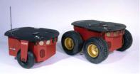
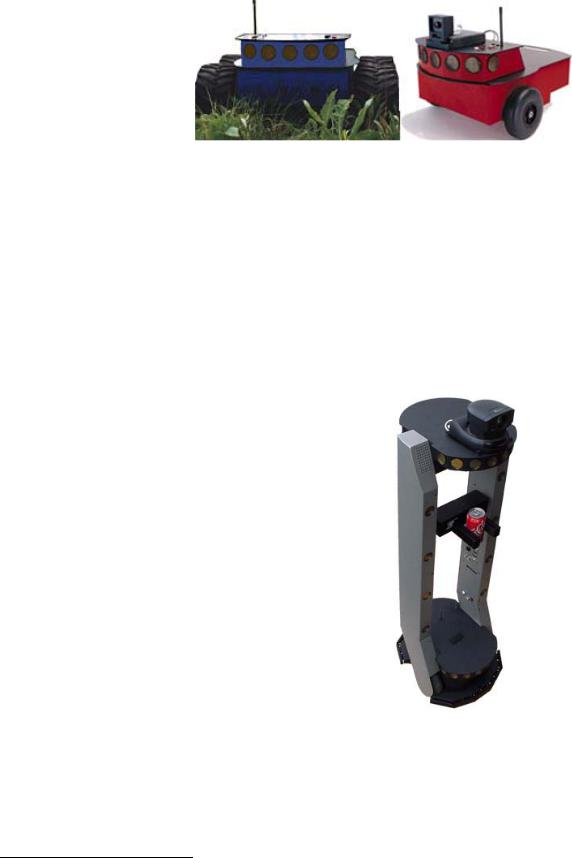
Figure 2. ActivMedia Robots
PIONEER REFERENCE PLATFORM
Pioneer is a family of mobile robots, both two-wheel and four-wheel drive, including the Pioneer 1 and Pioneer AT, Pioneer 2™ -DX, -DXe, -DXf, -CE, -AT, the Pioneer 2™-DX8/Dx8 Plus and -AT8/AT8 Plus, and the newest Pioneer 3-DX and - AT mobile robots. These small, research and development platforms share a common architecture and foundation software with all other ActivMedia robots including AmigoBot™, PeopleBot™ V1, Performance PeopleBot™, and PowerBot™ mobile robots. All employ a common client-server robotics control architecture.
ActivMedia robots set the standards for intelligent mobile platforms by containing all of the basic components for sensing and navigation in a real-world environment. They have become reference platforms in a wide variety of research projects, including several US Defense Advanced Research Projects Agency (DARPA) funded studies.
Every ActivMedia robot comes complete with a sturdy aluminum body, balanced drive system (two-wheel differential with caster or four-wheel skid-steer), reversible DC motors, motor-control and drive electronics, high-resolution motion encoders, and long-life, hotswappable battery power, all managed by an onboard microcontroller and mobilerobot server software.
Besides the open-systems ActivMedia Robotics Operating System (AROS) software onboard the robot controller, every ActivMedia robot also comes with a host of advanced robot-control client software applications and applications-development environments. Software development includes our own foundation ActivMedia Robotics Interface for Applications (ARIA), released under the GNU Public License, and complete with fully documented C++, Java, and Python libraries and source code. SRI International’s Saphira robotics development system with simulator and GUI, as well as support for advanced localization and gradient-based navigation comes bundled, too. Several third-party robotics applications development environments also have emerged from the research community for ActivMedia robots, including Ayllu from Brandeis University, Pyro from Bryn Mawr and Swarthmore Colleges, Player from the University of Southern California, and Carmen from Carnegie-Mellon University.
Every ActivMedia robot also comes with a plethora of expansion options, including builtin hardware support for sonar and bump sensors and lift/gripper effectors, as well as serial-port and server software support for a number of sensors, effectors, and control accessories, like an onboard PC system, automated docking/recharging system, laser range-finder, 5-DOF arm, robotic pan-tilt cameras, and much, much more.
PIONEER FAMILY OF MICROCONTROLLERS AND OPERATING SYSTEM SOFTWARE
The original Pioneer 1 mobile robot had a microcontroller based on the Motorola 68HC11 microprocessor and powered by Pioneer Server Operating System (PSOS) software. The first generation of Pioneer 2 and PeopleBot robots use a Siemens C166-based microcontroller and Pioneer 2 Operating System (P2OS) software. Now, all new
4
ActivMedia Robotics
ActivMedia robots, including Pioneer 3, Performance PeopleBot, and PowerBot, use a multifunctional Hitachi H8S-based microcontroller and new ActivMedia Robotics Operating System (AROS) software.2 The newest Pioneer 3 and 2 Plus platforms also sport an advanced motor-power board for high-power motor drives and systems power.
Although differing in some power and interfacing features, processing power, support for various sensors, and I/O, all ActivMedia Robotics’ server-operating system software— PSOS, P2OS, AmigOS, and now AROS—are upwardly compatible and virtually interchangeable. Accordingly, client software written to operate a six-year old Pioneer AT will work with a brand new Pioneer 3. We’ve taken great care to have all client commands for control of that original Pioneer 1 work identically in our latest robots. Client-server communications protocols over a serial communication link remain identical, too. See Chapter 6, ActivMedia Robotics Operating System, for details.
HITACHI H8S-BASED MICROCONTROLLER
Your H8S-based ActivMedia robot also has a variety of expansion power and I/O ports for attachment and close integration of a client PC, sensors, and a variety of accessories— all accessible through a common application interface to the robot server software, AROS. Features include:
18 MHz Hitachi H8S/2357 with 32K RAM and 128K FLASH Optional 512K FLASH or SRAM expansion
3 RS-232 serial ports (4 connectors) configurable from 9.6 to 115.2 kbaud 4 Sonar arrays of 8 sonar each
2 8-bit bumpers/digital input connectors
1 P2 Gripper/User I/O connector with 8-bits digital I/O and 1 analog input 1 Expansion/bus connector containing
5 Analog input
2 Analog output
8-bit I/O bus with r/w and 4 chip-selects 2-axes, 2-button joystick port
User Control Panel
Controller HOST serial connector
Main power and bi-color LED battery level indicators
AUX and RADIO power switches with related LED indicators RESET and MOTORS pushbutton controls
Piezo buzzer
Motor/Power Board (drive system) interface with PWM and motor-direction control lines and 8-bits of digital input
With the onboard PC option, your ActivMedia robot becomes an autonomous agent. With Ethernet-ready onboard autonomy, your robot even becomes an agent for multiintelligence work.
PLUS MOTOR-POWER BOARD
The new Pioneer 3 and previous Pioneer 2-Plus robots come with an advanced motorpower board. It can be configured as a plug-and-play replacement for some older Pioneer 2s, as well.
Besides expanded user-power connectors and connections for ease and versatility of use, the new board supplies three to four times the motor power than the original Pioneer 2 board. Accordingly, the Pioneer 3 and 2-Plus platforms operate more robustly over rougher terrain (fewer stalls!) and carry significantly more payload when compared with their predecessors. And because of the power improvements, the Pioneer 3-AT and 2-
2AmigoBot has an H8S-based controller, too, but uses the AmigoBot Operating System tailored for its electronics.
5
What is Pioneer?
AT8 Plus now come with a lower motor-gearhead reduction for faster speeds, even with much-improved turning power.
CLIENT SOFTWARE
All ActivMedia robots operate as the server in a client-server environment: Their controllers handle the low-level details of mobile robotics, including maintaining the platform’s drive speed and heading over uneven terrain, acquiring sensor readings, such as the sonar, and managing attached accessories like the Gripper. To complete the client-server architecture, ActivMedia robots require a client connection: software running on a computer connected with the robot’s controller via the HOST serial link and which provides the high-level, intelligent robot controls, including obstacle avoidance, path planning, features recognition, localization, gradient navigation, and so on.
An important benefit of ActivMedia Robotics’ client-server architecture is that different robot servers can be run using the same high-level client. For example, we provide a robot simulator that runs on the host machine that can look and act just like your real robot. With the Simulator, you may conveniently perfect your application software and then run it without modification on any ActivMedia robot. Several clients also may share responsibility for controlling a single mobile server, which permits experimentation in distributed communication, planning, and control.
Currently available client software and development environments for the Microsoft Windows or Red Hat© Linux-based computing platform of your choice include:3
ActivMedia Robotics Interface for Applications (ARIA) SRIsim ActivMedia robot simulator
SRI’s Saphira client-development suite with Colbert
Versions and updates for supported computing platforms are available to passwordregistered customers for download from our software website:
http://robots.activmedia.com
ARIA
The ActivMedia Robotics Interface for Applications (ARIA) is a C++-based open-source development environment that provides a robust client-side interface to a variety of intelligent robotics systems, including your ActivMedia robot’s controller and accessory systems.
ARIA is the ideal platform for integration of your own robot-control software, since it neatly handles the lowest-level details of client-server interactions, including serial communications, command and server-information packet processing, cycle timing, and multithreading, as well as a variety of accessory controls, such as for the PTZ robotic camera, the P2-Gripper,
scanning laser-range finder, motion gyros, among many others.
3Some software may come bundled with your robot. Other packages require purchase for licensing. Some software is also available for alternative operating systems, such as Macintosh, SunOS, Solaris, and BSD Unix.
6
ActivMedia Robotics
What’s more, it comes with source code so that you may examine the software and modify it for your own sensors and applications.
Saphira
Saphira, including the Colbert language, is a full-featured robotics control environment developed at SRI International’s Artificial Intelligence Center. Saphira and its ARIA foundation form the robotics-control and applications-development foundation for most ActivMedia robot owners and users. The complete, licensed Saphira robotics development environment, including C/C++ libraries, GUI interface and Simulator, comes bundled with your ActivMedia robot.
Laser Navigation and Localization
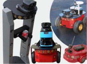
Figure 4. ActivMedia’s robot servers require a computer, typically a Windows©- or RedHat© Linux-based PC, to run client software for intelligent robotics command and control operations.
A separate Laser Navigation and Localization package is available as a Saphira add-on. It is a comprehensive suite of software tools and applications by which, with your laser- scanning/range-finder enabled robot, you automatically create, edit, and use maps and floor plans for advanced robotics applications including localization and gradient navigation.
SUPPORTING SOFTWARE
Simulator
The SRIsim Simulator is a connection option that provides a virtual replacement for your ActivMedia robot. By connecting to the simulator instead of a real robot, you can test your client programs, maps, and so on, when the real robot isn’t practical or available.
Mapper
Mapper provides the tools you need to construct a map of your robot’s real operating space (“world”).
THE PIONEER LEGACY
Commercially introduced in Summer 1995, Pioneer 1 is the original platform. It came with a single-board 68HC11-based robot microcontroller and the Pioneer Server Operating System (PSOS) software. Its low-cost and high-performance caused an explosion in the number of researchers and developers who now have access to a real, intelligent mobile robotic platform.
7
What is Pioneer?
Pioneer 1 and AT
Intended mostly for indoor use on hard, flat surfaces, the Pioneer 1 had solid rubber tires and a twowheel differential, reversible drive system with a rear caster for balance. The Pioneer 1 came standard with seven
sonar range finders (two Figure 5. The original Pioneer 1s side-facing and five
forward-facing) and integrated wheel encoders.
Software-wise, the Pioneer 1 initially served as a platform for SRI International's AI/fuzzy logic-based Saphira robotics applications development. But it wasn't long before its open architecture became the popular platform for the development of a variety of alternative robotics software environments.
Many developers created software that interfaced directly with PSOS. Others extended the capabilities of Saphira (PAI and P-LOGO are two good examples), while others have implemented alternative robotics-control architectures, such as the subsumption-like Ayllu.
Functionally and programmatically identical to the Pioneer 1, the four-wheel drive, skid-steering Pioneer AT was introduced in the Summer of 1997 for operation in uneven indoor and outdoor environments, including loose, rough terrain.
Except for the drive system, there are virtually no operational differences between the Pioneer AT and the Pioneer 1: The integrated sonar arrays and microcontrollers are the same. The accessories available for the Pioneer 1 also work with the Pioneer AT. Further, applications developed for the Pioneer 1 work with little or no porting to the Pioneer 2s and 3s.
Pioneer 2 and PeopleBot
The next generation of Pioneer Mobile Robots— including the Pioneer 2-DX, -CE, and -AT, introduced in Fall 1998 through Summer 1999, improved upon the Pioneer 1 legacy while retaining its many important advantages.4 Indeed, in most respects, particularly with applications software, Pioneer 2 works identically to Pioneer 1 models.
The ActivMedia Robotics Pioneer 2 models -DX, - DE, -DXe, -DXf, and -AT, and the V1 and Performance PeopleBot robots used a high-
Figure 6. The Performance PeopleBot sports an attractive body design and bundled systems, including voice synthesis and recognition for human-interaction research and applications.
4Price/performance ratio included! The much more capable and expandable Pioneer 2 was introduced four years later for just a few hundred dollars (US) more than the original Pioneer 1.
8

ActivMedia Robotics
performance 20 MHz Siemens 88C166-based microcontroller, with independent motor/ power and sonar-controller boards for a versatile operating environment. The controller had two RS232-standard communications ports and an expansion bus to support the many accessories available for your ActivMedia robot, as well as your own custom attachments.
Sporting a more holonomic body, larger wheels and stronger motors for better indoor performance, Pioneer 2-DX, -DXe, -DXf, and -CE models, like Pioneer 1, are two-wheel,
differential-drive mobile robots.
The four-wheel drive Pioneer 2-AT has independent motor drivers. Unlike its Pioneer AT predecessor, the Pioneer 2-AT comes with a stall-detection system and inflatable pneumatic tires with metal wheels for much more robust operation in rough terrain, as well as the ability to carry nearly 30 kilograms (66 lbs) of payload and climb a 60-percent grade. The newest version of the 2-AT, introduced in mid-2001, includes an integrated joystick port for manual operation and a hinged top-plate for easy access to the internal systems.
Other Pioneer 2-like robots include the Performance PeopleBot robots, which were introduced in 2000. They are architecturally
Pioneer 2 robots, but with stronger motors and integrated human-interaction features, including a pedestal extension, integrated voice and sound synthesis and recognition— ideal for human-interaction studies as well as for commercial and consumer mobilerobotics applications.
New Pioneer 3 and Recent Pioneer 2-DX8, -AT8, and Plus Mobile Robots
Two new models of Pioneer 2 appeared in the Summer of 2002, two more at the beginning of 2003, and the Pioneer 3 debuted in the Summer of 2003. They are the topics of this manual: the Pioneer 3-DX and –AT, and Pioneer 2-DX8/DX8 Plus and – AT8/AT8 Plus mobile robots. All sport a microcontroller based on the Hitachi H8S microprocessor, with new control systems and I/O expansion capabilities. The Pioneer 3 and 2-Plus robots also have new, more powerful motor/power systems for better navigational control and payload.5
Software-wise, Pioneers all are compatible with all other ActivMedia robots, including Pioneer 1. The new ActivMedia Robotics Operating System (AROS) software extends— but does not replace—the original PSOS and P2OS. This means that even programs that interface at the lowest communication levels will work with all Pioneer 1, 2, and 3 platforms. This also means that the higher level clients and applications, including Saphira, ARIA, and others including your own software, will work with AROS and any host ActivMedia robot just as they had worked with PSOS or P2OS.6 Of course, you will have to extend your client software, as we have done with Saphira, ARIA, and others, in order to take full advantage of AROS.
To the relief of those who have invested years in developing software for Pioneer 1 and 2, Pioneer 3 truly does combine the best of the new mobile robot technologies with ActivMedia’s tried-and-true robot architecture.
5The interim Pioneer 2-DXf had the same, more-powerful motors as the DX8s and AT8 Plus.
6The two-time gold medal winners of the International RoboCup robot soccer competition used Pioneer 1s one year and quickly converted to Pioneer 2s in the next year.
9
What is Pioneer?
MODES OF OPERATION
You may operate your Pioneer 2 and 3 robots in one of five modes:
Server
Joydrive
Self-test
Maintenance
Standalone
Server Mode
The Pioneer H8S microcontroller comes with fully programmable 128K FLASH and 32K dynamic RAM included in its Hitachi 18 MHz H8S/2357 microprocessor. An additional 512K of dynamic RAM or FLASH-ROM is available as optional equipment. But we don't recommend that you start learning H8S programming. Rather, the robot comes to you installed with the latest AROS robotics server software.
In conjunction with client software, such as ARIA or Saphira, running on an onboard or other user-supplied computer, AROS lets you take advantage of modern client-server and robot-control technologies to perform advanced robot tasks.
Most users run their ActivMedia robot in server mode, because it gives them quick, easy access to its robotics functionality while working with high-level software on a familiar host computer.
Maintenance and Standalone Modes
For experiments in microcontroller-level operation of your robot’s functions, you may reprogram the onboard FLASH for direct and standalone operation of your ActivMedia robot. We supply the means to download, but not the microcontroller's programming software, for you to work in standalone mode.
The utilities we provide for you to reprogram the H8S-based controller's FLASH also may be used to update and upgrade your robot’s AROS. In a special Maintenance Mode, you also adjust your robot’s operating parameters that AROS uses as default values on startup or reset. See Chapter 7, Updating & Reconfiguring AROS, for much more detail.
We typically provide the maintenance utilities and AROS upgrades free for download from our website, so be sure to sign up for the pioneer-users email newslist. That's where we notify our customers of the upgrades, as well as where we provide access to ActivMedia robot users worldwide.
Joydrive and Self Test Modes
Finally, we provide onboard software and controller hardware that lets you drive the robot from a tethered joystick when not otherwise connected with a controlling client. And we provide some self-test programs that exercise your robot’s hardware and software. We examine these modes in some detail in Chapter 5, Joydrive and Self-Tests.
10
ActivMedia Robotics
Chapter 3 Specifications & Controls
ActivMedia’s Pioneer robots may be smaller than most, but they pack an impressive array of intelligent mobile robot capabilities that rival bigger and much more expensive machines. For example, the Pioneer 3-DX with onboard PC is a fully autonomous intelligent mobile robot. Unlike other commercially available robots, Pioneer’s modest size lends itself very well to navigation in tight quarters and cluttered spaces, such as classrooms, laboratories, and small offices.
At the same time, the powerful AROS server with ActivMedia Robotics client software is fully capable of mapping its environment, finding its way home, and performing other sophisticated path-planning tasks.
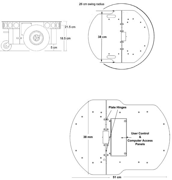
Figure 8. Pioneer 3-DX’s physical dimensions and swing radius
PHYSICAL CHARACTERISTICS
Weighing only 9 kg (20 pounds |
|
|||||
with one battery), the basic |
|
|||||
Pioneer 3- and 2-DX8/DX8 Plus |
|
|||||
mobile robots are lightweight, |
|
|||||
but their strong aluminum body |
|
|||||
and |
solid |
construction |
make |
|
||
them virtually indestructible. |
|
|||||
These characteristics also permit |
|
|||||
them |
to |
carry |
extraordinary |
|
||
payloads: The new Pioneer 3- |
|
|||||
DX can carry up to 23 Kg (50 |
|
|||||
lbs.) additional weight; the 3-AT |
|
|||||
can carry over 35 Kg (70 lbs.) |
|
|||||
more! Yet, Pioneer 2s and 3s |
|
|||||
are lightweight enough that it is |
|
|||||
also as easy to transport as a |
|
|||||
suitcase a task |
made |
even |
Figure 9. Pioneer 3-AT’s console and hinged deck |
|||
easier |
by |
the |
DX's |
built-in |
||
|
||||||
handle.
11
Specifications and Controls
MAIN COMPONENTS
ActivMedia robots are composed of several main parts:
Deck
Motor Stop Button
User Control Panel
Body, Nose, and Accessory Panels
Sonar Array(s)
Motors, Wheels, and Encoders
Batteries and Power
Deck
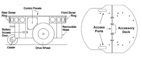
Figure 10. Components of the Pioneer 3
The original Pioneer 2-DX, CE, and AT decks are one piece the top plate of the robot. The newer DXe and AT, and now the DX8/DX8 Plus, AT8/AT8 Plus, and Pioneer 3 models have hinged top-plates which give you much easier access to the internal components of the robot. See Chapter 8, Maintenance & Repair, for access details.
The robot’s deck is simply the flat surface for mounting projects and accessories, such as the PTZ Robotic Camera and the laser range finder. Feed-through slots on each side of the DX deck let you conveniently route cables to the accessory panels on the side panels of the robot. A removable plug in the middle of the deck on all models gives you convenient access to the interior of the robot.
When mounting accessories, you should try to center the robot's payload over the drive wheels. If you must add a heavy accessory to the edge of the deck, counterbalance the weight with a heavy object on the opposite end. A full complement of batteries helps balance the robot, too.
Motor Stop Button
All new Pioneer 3-AT and, upon request, some new Pioneer 3-DX robots have a STOP button at the rear of the Deck. Press and release it to immediately disengage the robot’s motor power. It will also cause a stall and result in incessant beeping from the onboard piezo speaker (see User Controls below).
Press the STOP button in to re-engage motor power and stop that incessant beeping noise. Note that you may also have to re-engage the motor controls when connected with a client, either by manually pressing the MOTORS button on the User Control Panel, or through a special client command. Read on…
12
ActivMedia Robotics
User Control Panel
The User Control Panel is where you have access to the AROS-based onboard microcontroller. Found inside the AT’s hinged access panel on the deck or on the leftside panel of the DX, it consists of control buttons and indicators, and an RS232compatible serial port with a 9-pin DSUB connector.
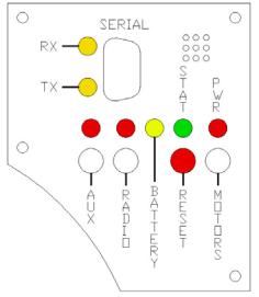
The red PWR LED is lit whenever main power is applied to the robot. The green STAT LED state depends on the operating mode and other conditions. It flashes slowly when the controller is awaiting a connection with a client and flashes quickly when in joydrive mode or when connected with a client and the motors are engaged. It also flashes moderately fast when the controller is in maintenance mode.
The BATTERY LED’s apparent color depends on your robot’s battery voltage: green when fully charged (>12.5 volts) through orange, and finally red when the voltage is below 11.5. When in maintenance mode, however, the BATTERY LED glows bright red only, regardless of battery charge.
A built-in piezo buzzer (audible through the holes just above the STAT and PWR LEDs) provides audible clues to the robot’s state, such as upon successful startup of the controller and a client connection. An AROS client command lets you program the buzzer, too, to play your own sounds.
The SERIAL connector, with incoming |
|
|
and outgoing data indicator LEDs (RX |
|
|
and TX, respectively), is through where |
|
|
you may interact with the H8S |
|
|
microcontroller from an offboard |
|
|
computer for tethered client-server |
|
|
control and for AROS system |
|
|
maintenance. The port is shared |
|
|
internally by the HOST serial port, to |
|
|
which we connect the onboard |
|
|
computer or radio modem/Ethernet. |
|
|
Digital switching circuitry disables the |
or |
|
internal HOST serial port if the computer |
||
radio modem is OFF. However, serial |
|
|
port interference will be a problem if |
|
|
the HOST and User Control SERIAL ports |
|
|
are both occupied and engaged. |
|
|
Accordingly, remove the cable from |
Figure 11. P3-DX User Control Panel |
|
the SERIAL port if you plan to connect |
||
|
||
with the controller through the onboard |
|
|
radio modem or PC. |
|
RADIO and AUX are pushbutton switches which engage or disengage power to the respective devices on the Motor/Power Interface board. See Appendix B for power connections. Respective red LEDs indicate when power is ON.
The red RESET pushbutton acts to unconditionally reset the H8S controller, disabling any active connections or controller-attached devices, including the motors.
The white MOTORS pushbutton’s actions depend on the state of the controller. When connected with a client, push it to manually enable and disable the motors, as its label implies. When not connected, press the pushbutton once to enable joydrive mode, and again to enable the motors self-test.
13
Specifications and Controls
To engage AROS maintenance mode, press and hold the white MOTORS button, press and release the red RESET button, then release MOTORS. In the future, the white MOTORS button may engage other modes, such as when in AROS standalone mode.
Body, Nose, and Accessory Panels
Your ActivMedia robot’s sturdy, but lightweight aluminum body houses the batteries, drive motors, electronics, and other common components, including the front and rear sonar arrays. The body also has sufficient room, with power and signal connectors, to support a variety of robotics accessories inside, including an A/V wireless surveillance system, radio modems or radio Ethernet, onboard computer, laser range finder, and more.
On all models except the Pioneer 2-CE, a hinged rear door gives you easy access to the batteries, which you may quickly hot-swap to refresh any of up to three batteries.
The nose is where we put the onboard PC. The nose is readily removable for access: Simply remove two screws from underneath the front sonar array. A third screw holds the nose to the bottom of the AT’s body. The DX nose is hinged at the bottom.
Once the mounting screws are removed, simply pull the nose away from the body.7 This provides a quick and easy way to get to the accessory boards and disk drive of the onboard PC, as well as to the sonar gain adjustment for the front sonar array. The nose also is an ideal place for you to attach your own custom accessories and sensors.
All DX’s come with a removable right-side panel through which you may install accessory connectors and controls. A special side panel comes with the onboard PC option, for example, which gives users monitor, keyboard, mouse, and 10Base-T Ethernet access, as well as the means to reset and switch power for the onboard computer.
AT’s come with a single access panel in the deck. Fastened down with finger-tight screws, the User Control Panel and onboard computer controls are accessible beneath the hinged door.
All models come with an access port near the center of the deck through which to run cables to the internal components.
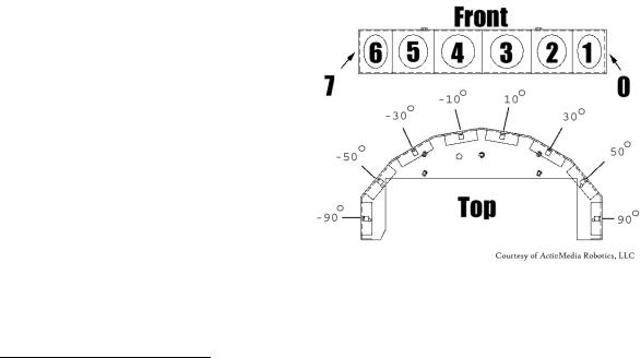
Sonar Arrays with Gain Adjustment |
|
|
Natively, H8S/AROS-based ActivMedia |
|
|
robots support up to four sonar arrays, |
|
|
each with eight transducers that |
|
|
provide object detection and range |
|
|
information for collision avoidance, |
|
|
features recognition, localization, and |
|
|
navigation. The sonar positions in all |
|
|
Pioneer 2 and 3 arrays are fixed: one |
|
|
on each side, and six facing outward |
|
|
at 20-degree intervals. Together, fore |
Figure 12. Pioneer 3 sonar array |
|
and aft sonar arrays provide 360 |
||
|
||
degrees of nearly seamless sensing for |
|
|
the platform. |
|
7With older Pioneer 2 models, you also needed to remove the Gripper before removing the Nose. With the DXE, and newer DXs and ATs, the Nose and Gripper come off together, so you only need to remove the Nose’s mounting screws.
14
ActivMedia Robotics
Each sonar array comes with its own driver electronics for independent control. Each array’s sonar are multiplexed; the sonar acquisition rate is adjustable, normally set to 25 Hz (40 milliseconds per sonar per array). Sensitivity ranges from ten centimeters (six inches) to over four meters, depending on the ranging rate. You may control the sonar’s firing pattern through software, too; the default is left-to-right in sequence 0 to 7 for each array. See the AROS chapters 6 and 7 for details.
The driver electronics for each array is calibrated at the factory. However, you may adjust the array’s sensitivity and range to accommodate differing operating environments. The sonar gain control is on the underside of the sonar driver board, which is attached to the floor of each sonar module.
Sonar sensitivity adjustment controls are accessible directly, although you may need to remove the Gripper to access the front sonar, if you have that accessory attached.8 For the front sonar, for instance, locate a hole near the front underside of the array through which you can see the cap of the sonar-gain adjustment potentiometer. Using a small flat-blade screwdriver, turn the gain control counterclockwise to make the sonar less sensitive to external noise and false echoes.
Low sonar-gain settings reduce the robot’s ability to see small objects. Under some circumstances, that is desirable. For instance, attenuate the sonar if you are operating in a noisy environment or on uneven or highly reflective floor a heavy shag carpet, for example. If the sonar are too sensitive, they will “see” the carpet immediately ahead of the robot as an obstacle.
Increase the sensitivity of the sonar by turning the gain-adjustment screw clockwise, making them more likely to see small objects or objects at a greater distance. For instance, increase the gain if you are operating in a relatively quiet and open environment with a smooth floor surface.
Motors, Wheels, and Position Encoders
Pioneer 2’s and 3’s drive systems use high-speed, high-torque, reversible-DC motors, each equipped with a high-resolution optical quadrature shaft encoder for precise position and speed sensing and advanced dead-reckoning. Motor gearhead ratios and encoder ticks per revolution vary by robot model. However, AROS converts most client commands and server information from platform independent distance units into platform-dependent encoder ticks, as expressed in the Ticksmm FLASH parameter, calculated as the encoder counts (4 * 500, typically) divided by the product of wheel circumference times gear ratio.
Inflate the tires evenly
or your robot won’t drive properly.
All Pioneer 3 robots now come with pneumatic tires so that you may configure your robot for differing terrains. In any configuration, however, be careful to inflate the tires evenly and adjust the respective Ticksmm and rotational Revcount FLASH parameters for proper operation. We ship with the tires inflated to 23 psi each.
BATTERIES AND POWER
Except when outfitted with the automated docking/charging system (see below), Pioneer 2 and 3 robots may contain up to three, hot-swappable, seven ampere-hour, 12 volts direct-current (VDC) sealed lead/acid batteries (total of 252 watt-hours), accessible through a hinged and latched rear door. We provide a suction cup tool to help grab
8 It’s easier to remove the DXE’s Nose with Gripper attached.
15

Specifications and Controls
and slide each battery out of its bay. Spring contacts on the robot’s battery power board alleviate the need for manually attaching and detaching power cables or connectors.
Balance the batteries in your robot.
Battery life, of course, depends on the configuration of accessories and motor activity. AT charge life typically ranges from two to three hours. The DX runs continuously for six hours or more; up to four hours with onboard computer. If you don’t use the motors, your robot’s microcontroller will run for several days on a single battery charge.
IMPORTANT: Batteries have a significant impact on the balance and operation of your robot. Under most conditions, we recommend operating with three batteries. Otherwise, a single battery should be mounted in the center, or two batteries inserted on each side of the battery container.
Battery Indicators and Low Voltage Conditions
The User Control Panel has a bi-color LED labeled BATTERY that visually indicates current battery voltage. From approximately 12.5 volts and above, the LED glows bright green. The LED turns progressively orange and then red as the voltage drops to approximately 11.5 volts.
Aurally, the User Control Panel’s buzzer, if active (see the AROS SoundTog client command and FLASH parameter), will sound a repetitive alarm if the battery voltage drops consistently below the FLASH LowBattery level. If the battery voltage drops below 11 volts, the microcontroller’s watchdog server automatically shuts down a client connection and notifies the computer, via the HOST RI (ring indicator) pin, to shut down and thereby prevent data loss or systems corruption due to low batteries.
Recharging
Typical battery recharge time using the recommended accessory (800 mA) charger varies according to the discharge state; it is roughly equal to three hours per volt per battery. The Power Cube accessory allows simultaneous recharge of three swappable batteries outside the robot.
With the optional high-speed (4A maximum current) charger, recharge time is greatly reduced. It also supplies sufficient current to continuously operate the robot and onboard accessories, such as the onboard PC and radios. But with the higher-current charger, care must be taken to charge at least two batteries at once. A single battery may overcharge and thereby damage both itself and the robot.
The new automated docking/recharging system is the best option. Because its integrated charge-management system has sufficient power and actively adjusts to system loads, it can run your robot's onboard systems while properly and optimally recharging its batteries. And because the charging mechanism may be operated independently of your robot's systems power, you may start up and shut down your robot and its onboard systems without disturbing the battery charging cycle.
All our recommended chargers are specifically designed for safe lead-acid battery recharging. Indicators on the module’s face show fast-charge mode (typically an orange LED) in which the discharged batteries are given the maximal current, and trickle mode (green LED indicator), which the batteries are given only enough current to remain at full charge.
16
ActivMedia Robotics
DOCKING/CHARGING SYSTEM
The Pioneer 3/PeopleBot docking/charging accessory is both a manual and an automated mechanism. Onboard controls, triggered either by the DEPLOY CHARGER button near the manual CHARGE port, or by H8S controller-mediated client commands, deploy actuated contacts on the bottom of the robot, which in turn seat onto the charging platform. Then, when activated by an IR-based, unique frequency-modulated signal from the robot, the charger platform delivers up to 17 VDC @ 11.5 A to its plates.
While connected, onboard circuitry conditions the power to optimally charge the three 21-Ahr, 12 VDC lead-acid batteries (6 A charging current max) and provides sufficient power (up to 5.5 A) for operation of all onboard systems.
The charging mechanism and onboard power conditioning circuitry can be retrofitted to all Pioneer 3 and some Pioneer 2 and PeopleBot robots; all require return to the factory.
Manual Operation (Robot Power OFF)
With MAIN POWER off, place the robot over the charge platform so that its charging contacts are perpendicular to and, when deployed, contact the charger plates. Note that no charging power is applied to the plates on the platform; only low signal (5VDC @ <300mA) power for the IR detectors.
Press and hold the DEPLOY CHARGER button to manually deploy the charge mechanism on the bottom of the robot. Hold for a few seconds, but not more than 10 seconds. Charging is activated by positive contact with the charging platform. In that case, the charge lamp on the charger unit will light and the robot's contacts will remain deployed when you release the DEPLOY CHARGER button. Otherwise, the mechanism will retract. In that case, re-position the robot and try again.
The robot's charging mechanism automatically retracts if you press the DEPLOY CHARGER button while charging, if you move the robot on the docking platform and lose positive charging contact, or if you remove power from the charger unit. In all cases, charging power is removed immediately from the docking platform when not actively engaged by the robot.
Manual Operation (Robot Power and Systems ON)
Because the automated docking/charging system’s charger and integrated circuitry actively adjusts to system loads, it can run your robot's onboard systems while properly and optimally recharging its batteries. And because the charging mechanism may be operated independently of your robot's systems power, you may start up and shut down your robot and its onboard systems without disturbing the battery charging cycle, if engaged.
For example, with MAIN POWER on, use joystick mode to position the robot onto the charging platform. Then reset the robot controller and manually deploy the charging mechanism as described in the section above. Thereafter, switch MAIN POWER off, or conversely, start up and shut down other onboard systems, including the PC, camera, laser, and other accessories, to proceed with development work without disturbing battery recharging.
The same conditions apply to remove charging power and retract the robot's charging mechanism with the robot’s MAIN POWER on as well as off. In addition, engaging the motors, such as when you press the white MOTORS button on the robot controller to engage joystick/self-tests mode, also disengages recharging and retracts the charging
17
Specifications and Controls
mechanism. And the charging mechanism will not activate until you disengage the motors, either manually or programmatically.
RADIO CONTROLS AND ACCESSORIES
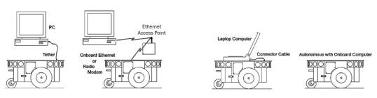
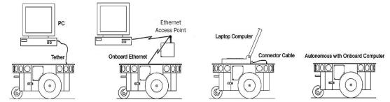
All ActivMedia robots are servers in a client-server architecture. You supply the client computer to run your intelligent mobile-robot applications. The client can be either an onboard piggy-back laptop or embedded PC, or an offboard PC connected through radio modems or wireless serial Ethernet. In all cases, that client PC must connect to the HOST serial port of the robot’s microcontroller in order for the robot and your software to work.
For the piggyback laptop or embedded PC, that serial connection is a cable. Radio modems simply replace that serial cable with a wireless tether. Accordingly, if you have radio modems, one is inside your robot and connected to the controller’s HOST serial port, and the other modem plugs into a serial port on some offboard computer where you run your client software. Hence, in these configurations, there is one dedicated client computer. (See Appendix C for radio modem settings.)
Figure 13. Client-server connection options.
Radio Ethernet is a little more complicated because it lets you use many different computers on the network to become the robot’s client. A special onboard SerialEthernet accessory that we provide is a standard wireless Ethernet radio which connects to your local TCP/IP network through an Access Point. But it’s different from most standard wireless Ethernet devices in that it also connects to the HOST serial port on the robot’s microcontroller. It works by automatically translating network-based Ethernet packet communications into streaming serial for the robot controller and back again. Accordingly, you may run the robot’s client on any network PC just as if that client PC were connected directly to the robot’s controller. (See Appendix D for Serial Ethernet settings.)
A major disadvantage of the wireless Ethernet-to-serial device, however, as well as for radio modems, is that they require a constant wireless connection with the robot. Disruption of the radio signal—a common occurrence in even the most modern installations—leads to poor robot performance and very short ranges of operation.
This is why we recommend onboard client PCs for wider, much more robust areas of autonomous operation, particularly when equipped with their own wireless Ethernet. In this configuration, you run the client software and its interactions with the robot controller locally and simply rely on the wireless connection to export and operate the client controls, such as through X-Windows or VNCserver. Moreover, the onboard PC is often needed for local processing, such as to support a laser range finder or to capture and process live video for vision work.
18

ActivMedia Robotics
ONBOARD PC
Unlike the original Pioneer 1, Pioneer 2 and 3 robots are designed to support an onboard, internally integrated PC for fully autonomous operation. Mounted just behind the nose of the robot, the PC is a common EBX form-factor that comes with up to four serial ports, 10/100Base-T Ethernet, monitor, keyboard, and mouse ports, two USB ports, and support for floppy, as well as IDE hard-disk drives. For additional functionality, such as for sound, video framegrabbing, firewire or PCMCIA bus, and wireless Ethernet, the onboard PC accepts PC104 and PC104-plus (PCI bus-enabled) interface cards that stack on the motherboard.
Necessary 5 VDC power comes from a dedicated DC:DC converter, mounted nearby. A hard-disk drive is specially shock-mounted to the robot’s nose, in between a cooling fan and computer speaker.
The onboard PC communicates with the H8S microcontroller through its HOST serial port and the dedicated serial port COM1 under Windows or /dev/ttyS0 on Linux systems. Automatic systems on the microcontroller switch in that HOST-to-PC connection when PC-based client software opens the serial port. Otherwise, the PC doesn’t interfere with externally connected clients through the shared SERIAL port on the User Control Panel.
Note also that some signals on the H8S microcontroller’s HOST serial port as connected with the onboard PC or other accessory can be used for
automated PC shutdown or other utilities: Pin 4 (DSR) normally is RS232 high when the controller operates normally; otherwise it is low when reset or in maintenance mode. Similarly, pin 9 (RI) normally is low and goes RS232-level high when the robot’s batteries drop below a set (nominally 11 VDC) voltage level.
Computer Control Panel
User-accessible communication and control port connectors, switches, and indicators for the onboard PC are on the Computer Control Panel, found on the right side panel of the DX or in the hinged control well next to the User Controls of the AT.
Figure 15. AT computer and user controls
19
Specifications and Controls
The controls and ports use common connectors: standard monitor DSUB and PS/2 connectors on the mouse and keyboard. The Ethernet is a 10/100Base-T standard RJ-45 socket.
The ON/OFF slide switch directly controls power to the onboard PC—through Main Power, unlike some earlier versions of the onboard system which included a delayed power shutdown. The PWR LED lights when the computer has power.
The HDD LED lights when the onboard hard-disk drive is active. The RESET button restarts the PC.
Operating the Onboard PC
This is a brief overview of operating the onboard PC. Please consult the Computer Systems Documentation and the OS manufacturer’s documentation for more detail. ActivMedia Robotics’ software runs over either Microsoft Windows (currently Windows 2000®) or RedHat® Linux (currently version 7). Accordingly, we prefer (the latter, in particular) and support those OSes on the onboard PC.
When we perform the installation and configuration, we install our robotics and accessory software typically in /usr/local on Linux systems, or in C:\Program Files\ActivMedia Robotics under Windows. Of course, we install the appropriate drivers for the various accessory expansion cards, such as for a framegrabber or sound card. Please consult the respective ActivMedia Robotics application software manuals, such as the ActivMedia Color Tracking System (ACTS) for the video framegrabber or Festival for the sound card.
The first time you access the onboard PC, we recommend that you put the robot up on blocks so that it cannot inadvertently move and wreak havoc with external connections. Then attach a keyboard, monitor, and mouse to their respective sockets on the Computer Control Panel. Switch Main Power and then the computer power switch on.
After boot up, log in to the system. We’ve already created two users: one with common systems and file read/write permissions (guest) and one with full-access to the PC software and OS—root (Linux) or administrator (Windows). If there is a password (usually not) it’s activmedia. When connected directly, we recommend you log in with full-access capabilities so that you can do systems set up and maintenance, such as change passwords, add users, and set up the network. Do note that with Linux systems, you cannot log in remotely over the network as root; you must log in as a common user and use the ‘su –‘ command thereafter to attain superuser (root) status.
Once logged into a Windows system, it’s simply a matter of clicking the mouse to select programs and applications. With Linux, use the ‘startx’ command to enable the X- Windows desktop and GUI environment. You might perform some of the QuickStart activities this way, although motion is impractical because of the monitor, mouse, and keyboard tethers. You may remove these while the system is active at your own risk.
Rather, we suggest that you run the QuickStart activities from an offboard computer first (onboard PC off), and then tackle the networking issues to establish a remote, preferably wireless connection with your robot.
PC Networking
The RJ-45 connector on the Computer Control Panel provides wired 10/100Base-T Ethernet networking directly with the onboard PC. With the purchased option, we also install a PCMCIA adaptor card on the PC’s accessory stack and insert a 10GHz 11Mbps
20
Loading...