

Page 1

Operating Manual PNOZ ms2p HTL
Operating Manual PNOZ ms2p HTL
PNOZ ms2p HTL
Configurable Control System PNOZmulti
Operating Manual — No. 1001401-EN-02
Page 2

This document is a translation of the original document.
All rights to this documentation are reserved by Pilz GmbH & Co. KG. Copies may be made
for internal purposes.
Suggestions and comments for improving this documentation will be gratefully received.
Pilz®, PIT®, PMI®, PNOZ®, Primo®, PSEN®, PSS®, PVIS®, SafetyBUS p®, SafetyEYE®,
SafetyNET p®, the spirit of safety® are registered and protected trademarks of
Pilz GmbH & Co. KG in some countries.
SD means Secure Digital.
Preface
Page 3

Contents
Contents
Contents Page
Chapter 1 Introduction
1.1 Validity of documentation 1-1
1.1.1 Retaining the documentation 1-1
1.2 Overview of documentation 1-2
1.3 Definition of symbols 1-3
Chapter 2 Overview
2.1 Unit structure 2-1
2.1.1 Range 2-1
2.1.2 Unit features 2-1
2.2 Front view 2-2
Chapter 3 Safety
3.1 Intended use 3-1
3.1.1 System requirements 3-2
3.2 Safety regulations 3-3
3.2.1 Use of qualified personnel 3-3
3.2.2 Warranty and liability 3-3
3.2.3 Disposal 3-3
3.2.4 For your safety 3-4
Chapter 4 Function description
4.1 Device properties 4-1
4.1.1 Integrated protection mechanisms 4-1
4.1.2 Function description 4-1
4.1.2.1 Operation 4-1
4.1.2.2 Block diagram 4-1
4.2 Input device types 4-2
4.2.1 Proximity switch 4-2
4.2.1.1 Requirements of the proximity switches 4-2
4.2.2 Incremental encoders 4-3
4.2.2.1 Requirements of the incremental encoders 4-3
4.2.2.2 Adapter for incremental encoders 4-3
4.2.3 Incremental encoder and proximity switch
on one axis
4-3
Chapter 5 Installation
5.1 General installation guidelines 5-1
5.1.1 Dimensions 5-2
5.2 Connecting the base unit and expansion
modules
Pilz GmbH & Co. KG, Felix-Wankel-Straße 2, 73760 Ostfildern, Germany
Telephone: +49 711 3409-0, Telefax: +49 711 3409-133, E-Mail: pilz.gmbh@pilz.de
5-3
1
Page 4

Contents
Chapter 6 Commissioning
6.1 General wiring guidelines 6-1
6.2 Preparing for operation 6-2
6.2.1 Connection of proximity switches 6-2
6.2.2 Connection of the incremental encoder 6-3
6.2.2.1 Connect signals of the incremental
encoder to the speed monitor
6.2.2.2 Connect incremental encoder to the speed
monitor via an adapter
6.2.3 Connection of proximity switches and
incremental encoder
6.2.3.1 Proximity switch and incremental encoder
on various axes
6.2.3.2 Proximity switch and incremental encoder
on one axis
6.2.4 Connection examples 6-8
6.2.4.1 Connection of 2 proximity switches and an
incremental encoder
6.2.4.2 Connection of 4 proximity switches 6-9
6.2.4.3 Connection of an incremental encoder and
proximity switch on an axis
6-3
6-4
6-6
6-6
6-7
6-8
6-10
Chapter 7 Operation
7.1 Messages 7-1
7.2 Display elements 7-2
7.2.1 Display elements for device diagnostics 7-2
7.3 Signal statuses 7-3
7.4 Faults - malfunctions 7-4
Chapter 8 Technical details
8.1 Technical details 8-1
8.2 Order reference 8-3
Chapter 9 Application Examples
Pilz GmbH & Co. KG, Felix-Wankel-Straße 2, 73760 Ostfildern, Germany
2
Telephone: +49 711 3409-0, Telefax: +49 711 3409-133, E-Mail: pilz.gmbh@pilz.de
Page 5

1 Introduction
1.1 Validity of documentation
11000IntroductionIntroduction1-1.1Validity of docume ntation1100Validity of documenta tion1-Einf Gltigkeit der Dokumentation
This documentation is valid for the product PNOZ ms2p HTL. It is valid
Einf Einleitung_alt
until new documentation is published.
This operating manual explains the function and operation, describes
the installation and provides guidelines on how to connect the product
PNOZ ms2p HTL.
Verwendung/Bildunterschrift_multi_Drehzahlwchter
Speed monitor for connection to a base unit from the PNOZmulti modular safety system
Application of the product PNOZ ms2p HTL:
1.1.1 Retaining the documentation
Retaining the documentation1-Einf Aufbewahren
This documentation is intended for instruction and should be retained
for future reference.
Pilz GmbH & Co. KG, Felix-Wankel-Straße 2, 73760 Ostfildern, Germany
Telephone: +49 711 3409-0, Telefax: +49 711 3409-133, E-Mail: pilz.gmbh@pilz.de
1-1
Page 6

1 Introduction
1.2 Overview of documentation
1.2Overview of documentation1200Overview of documentation1-Einf_Uebersicht_plus_Applikationsbsp_BA
1 Introduction
The introduction is designed to familiarise you with the contents, structure and specific order of this manual.
2 Overview
This chapter provides information on the device's most important features.
3 Safety
This chapter must be read as it contains important information on safety
and intended use.
4 Function Description
This chapter describes the mode of operation of the device.
5 Installation
This chapter explains how to install the device.
6 Commissioning
This chapter describes the device's commissioning and wiring.
7 Operation
This chapter describes how to operate the product and gives tips in the
case of a fault.
8 Technical Details
9 Application Examples
1-2
Pilz GmbH & Co. KG, Felix-Wankel-Straße 2, 73760 Ostfildern, Germany
Telephone: +49 711 3409-0, Telefax: +49 711 3409-133, E-Mail: pilz.gmbh@pilz.de
Page 7
1 Introduction
1.3 Definition of symbols
1.3Definition of symbols1300Definition of symbols1-Einfhrung Zeichen
Information that is particularly important is identified as follows:
DANGER!
This warning must be heeded! It warns of a hazardous situation
that poses an immediate threat of serious injury and death and
indicates preventive measures that can be taken.
WARNING!
This warning must be heeded! It warns of a hazardous situation
that could lead to serious injury and death and indicates preventive measures that can be taken.
CAUTION!
This refers to a hazard that can lead to a less serious or minor
injury plus material damage, and also provides information on
preventive measures that can be taken.
NOTICE
This describes a situation in which the unit(s) could be damaged
and also provides information on preventive measures that can
be taken. It also highlights areas within the text that are of particular importance.
INFORMATION
This gives advice on applications and provides information on
special features.
Pilz GmbH & Co. KG, Felix-Wankel-Straße 2, 73760 Ostfildern, Germany
Telephone: +49 711 3409-0, Telefax: +49 711 3409-133, E-Mail: pilz.gmbh@pilz.de
1-3
Page 8

1 Introduction
1-4
Pilz GmbH & Co. KG, Felix-Wankel-Straße 2, 73760 Ostfildern, Germany
Telephone: +49 711 3409-0, Telefax: +49 711 3409-133, E-Mail: pilz.gmbh@pilz.de
Page 9

2 Overview
2.1 Unit structure
22000OverviewOverview2-2.1Unit structure2100Unit structure2-
2.1.1 Range
Range2-Eigenschaften
2.1.2 Unit features
Unit features2-Geraetemerkmale_Zusatz BA Einleitung
Scope of supply:
Expansion module PNOZ ms2p HTL
Jumper: 774 639
Drehzahlwaechter_Geraetemerkmale_PNOZ_ms2p
The product has the following features:
Monitoring of 2 independent axes
Connection per axis
– 1 incremental encoder
or
– 2 proximity switches
or
– 1 incremental encoder and 1 proximity switch
Measured variables:
– Standstill
– Speed (8 values can be set)
– Direction of rotation
Axis types, input device types and reset mode can be selected in the
PNOZmulti Configurator
Status indicators for
– Supply voltage
– Incremental encoder
–Proximity switch
– Axis status, standstill and excess speed
– Faults on the system
Proximity switch connection technology: Plug-in connection termi-
nals (either cage clamp terminal or screw terminal)
Incremental encoder connection technology:
RJ-45 female connector
Galvanic isolation between the connections X1, X12 and X22
Max. 4 speed monitors can be connected to the base unit
Pilz GmbH & Co. KG, Felix-Wankel-Straße 2, 73760 Ostfildern, Germany
Telephone: +49 711 3409-0, Telefax: +49 711 3409-133, E-Mail: pilz.gmbh@pilz.de
2-1
Page 10
2 Overview
HTL
15
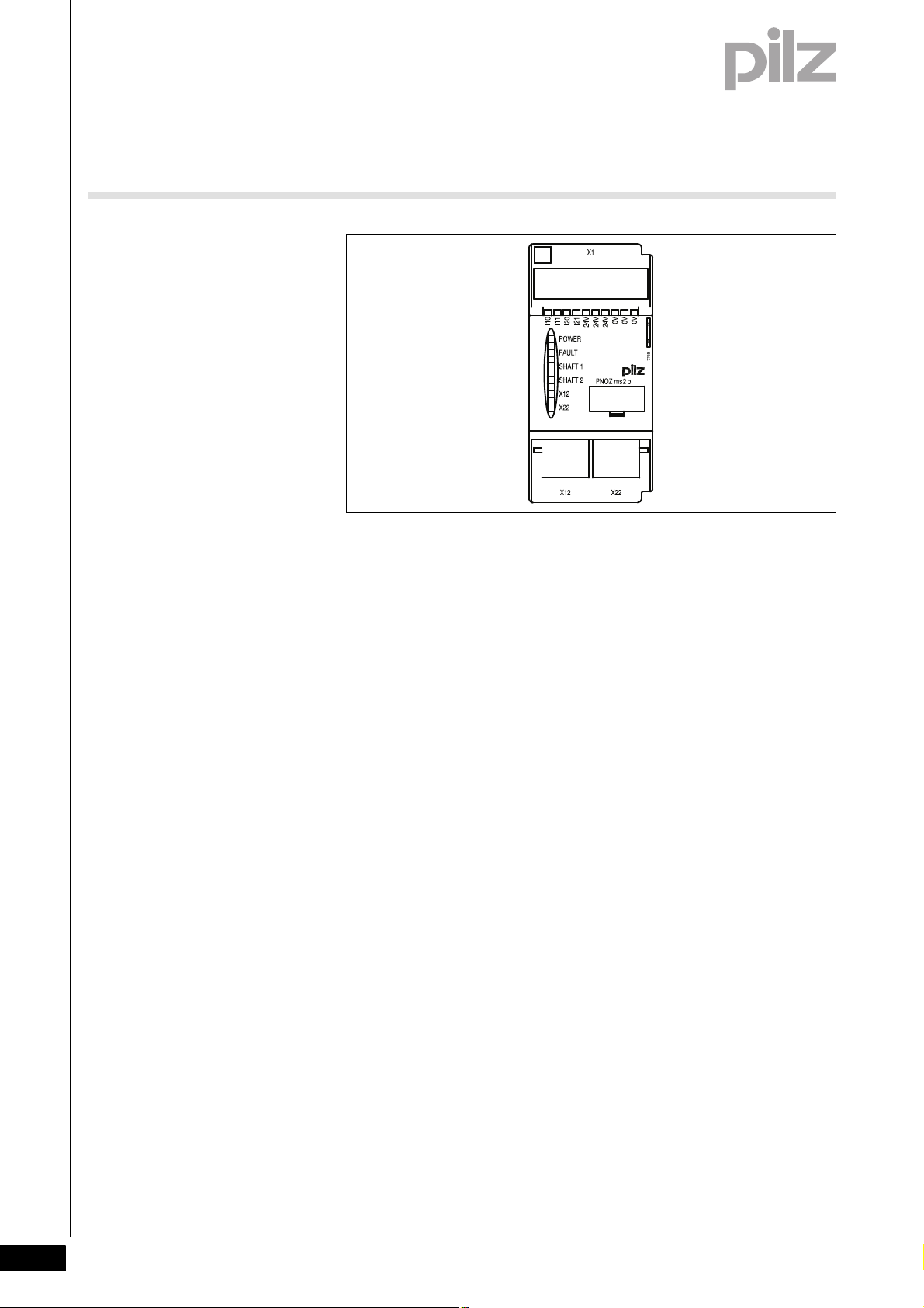
2.2 Front view
2.2Front view2200Front view2-Klemmenbelegung
Legende
Key:
X1:
– I10, I11:
connection terminals for proximity switch at axis 1
– I20, I21:
connection terminals for proximity switch at axis 2
– 0 V, 24 V:
supply connections
X12:
– female connector for the connection of an incremental encoder at
axis 1
X22:
– female connector for the connection of an incremental encoder at
axis 2
LEDs:
–POWER
–FAULT
–SHAFT 1
–SHAFT 2
–X12
–X22
2-2
Pilz GmbH & Co. KG, Felix-Wankel-Straße 2, 73760 Ostfildern, Germany
Telephone: +49 711 3409-0, Telefax: +49 711 3409-133, E-Mail: pilz.gmbh@pilz.de
Page 11

3 Safety
3.1 Intended use
33000SafetySafety3-3.1Intended use3100Intended use3-Bestimmung/Gertebeschreibung_multi_Drehzahlwaechter
Bestimmung/Gertebeschreibung_multi_Zusatz_Modul
Bestimmung/Gertebeschreibung_multi_System
Bestimmung/Gertebeschreibung_multi_Drehzahlwchter_Warnungen_ms1_2p_BA
The expansion module monitors standstill, speed and direction of rotation in accordance with EN ISO 13849-1 up to PL e and EN IEC 62061
up to SIL CL 3.
The expansion module may only be connected to a base unit from the
PNOZmulti modular safety system.
The modular safety system PNOZmulti is used for the safety-related interruption of safety circuits and is designed for use on:
E-STOP equipment
Safety circuits in accordance with VDE 0113 Part 1 and EN 60204-1
WARNING!
Users must take appropriate measures to detect or exclude
errors (e.g. slippage or broken shearpin) which cause the frequency of the encoder signal to no longer be proportional to the
monitored speed.
Appropriate measures are:
Using the monitored encoder to also control the drive
Mechanical solutions
Monitoring for broken shearpin by means of the speed monitor
WARNING!
A single-channel open circuit/input device error is recognised
and leads to a safe condition of the outputs at the relevant axis.
For applications in accordance with PL e and SIL CL 3, the
"Overspeed" output must be integrated into the safety function
in every operating mode and evaluated so that a shutdown
occurs if the output switches to a safe condition ("Overspeed"
output = "0").
Pilz GmbH & Co. KG, Felix-Wankel-Straße 2, 73760 Ostfildern, Germany
Telephone: +49 711 3409-0, Telefax: +49 711 3409-133, E-Mail: pilz.gmbh@pilz.de
3-1
Page 12

3 Safety
3.1 Intended use
CAUTION!
If there are frequency differences between tracks A and B of the
incremental encoder and/or between the proximity switches on
inputs I10 (I20) and I11 (I21), the PNOZmulti switches to a safe
condition if a frequency exceeds the configured standstill frequency. If the speed monitor detects different rotation directions, note the following:
With version 1.X devices the PNOZmulti changes to STOP.
With devices from version 2.0, the axis in question switches to
a safe condition. The safe condition is cleared again as soon
as the error is remedied. Hazards that can arise through an automatic restart must be excluded within the user program.
3.1.1 System requirements
System requirements3-Systemvoraussetzungen - Verweis auf Produktänderungen
Please refer to the "Product Modifications" document in the "Version
overview" section for details of which versions of the base unit and
PNOZmulti Configurator can be used for this product.
3-2
Pilz GmbH & Co. KG, Felix-Wankel-Straße 2, 73760 Ostfildern, Germany
Telephone: +49 711 3409-0, Telefax: +49 711 3409-133, E-Mail: pilz.gmbh@pilz.de
Page 13

3 Safety
3.2 Safety regulations
3.2Safety regulations3200Safety regulations3-
3.2.1 Use of qualified personnel
Use of qualified personnel3-Sich Qualif. Personal
The products may only be assembled, installed, programmed, commissioned, operated, maintained and decommissioned by competent persons.
A competent person is someone who, because of their training, experience and current professional activity, has the specialist knowledge required to test, assess and operate the work equipment, devices,
systems, plant and machinery in accordance with the general standards
and guidelines for safety technology.
It is the company's responsibility only to employ personnel who:
Are familiar with the basic regulations concerning health and safety /
accident prevention
Have read and understood the safety guidelines given in this descrip-
tion
Have a good knowledge of the generic and specialist standards ap-
plicable to the specific application.
3.2.2 Warranty and liability
Warranty and liability3-Sich Gewhrleistung
3.2.3 Disposal
Disposal3-Si ch Entsorgung
All claims to warranty and liability will be rendered invalid if:
The product was used contrary to the purpose for which it is intended
Damage can be attributed to not having followed the guidelines in the
manual
Operating personnel are not suitably qualified
Any type of modification has been made (e.g. exchanging compo-
nents on the PCB boards, soldering work etc.).
In safety-related applications, please comply with the mission time t
M
in the safety-related characteristic data.
When decommissioning, please comply with local regulations regard-
ing the disposal of electronic devices (e.g. Electrical and Electronic
Equipment Act).
Pilz GmbH & Co. KG, Felix-Wankel-Straße 2, 73760 Ostfildern, Germany
Telephone: +49 711 3409-0, Telefax: +49 711 3409-133, E-Mail: pilz.gmbh@pilz.de
3-3
Page 14

3 Safety
3.2 Safety regulations
3.2.4 For your safety
For your safety3-Zu Ihrer Sicherheit_multi_Module
The unit meets all necessary conditions for safe operation. However,
you should always ensure that the following safety requirements are
met:
This operating manual only describes the basic functions of the unit.
Information on the advanced functions can be found in the online help
for the PNOZmulti Configurator and in the PNOZmulti technical catalogue. Only use these functions after you have read and understood
the documentation. All necessary documentation can be found on the
PNOZmulti Configurator CD.
Do not open the housing or make any unauthorised modifications.
Please make sure you shut down the supply voltage when performing
maintenance work (e.g. exchanging contactors).
3-4
Pilz GmbH & Co. KG, Felix-Wankel-Straße 2, 73760 Ostfildern, Germany
Telephone: +49 711 3409-0, Telefax: +49 711 3409-133, E-Mail: pilz.gmbh@pilz.de
Page 15

4 Function description
I10 I11
Interface
to previous
module
Interface
to next
module
I20 I21 24 V 24 V 24 V
X12 X22
Axis 1
Axis 2
24 V
0 V
0 V 0 V 0 V
X1
4.1 Device properties
44000Function descriptionFunction description4-4.1Device properties4100Device properties4-
4.1.1 Integrated protection mechanisms
Integrated protection mechanisms4-Sicherheitseigenschaften_multi_allgemein
The relay conforms to the following safety criteria:
The circuit is redundant with built-in self-monitoring.
The safety function remains effective in the case of a component fail-
ure.
4.1.2 Function description
Function description4-
4.1.2.1 Operation
Operation4-Funktionen_multi_Drehzahlwächter_Inkrementalgeber_Naeherungsschalter
The speed monitor can independently monitor two axes for standstill,
speed and direction of rotation. The speed monitor signals the status of
the monitored values to the base unit. Depending on the safety circuit
loaded, the values can be transferred from the base unit, e.g. to a relay
output on the safety system. Incremental encoders and/or proximity detectors can be used to record the values.
4.1.2.2 Block diagram
Block diagram4-Blockschaltbild
The configuration of the speed monitor is described in detail in the
PNOZmulti Configurator's online help.
Pilz GmbH & Co. KG, Felix-Wankel-Straße 2, 73760 Ostfildern, Germany
Telephone: +49 711 3409-0, Telefax: +49 711 3409-133, E-Mail: pilz.gmbh@pilz.de
4-1
Page 16

4 Function description
Proximity switch 1
Proximity switch 2
4.2 Input device types
4.2Input device types4200Input device types4-
4.2.1 Proximity switch
Proximity switch4-
4.2.1.1 Requirements of the proximity switches
Requirements of the proximity swi tches4-Drehzahlwaechter_Naeherungsschalter_Anford
Only "pnp" type proximity switches may be used (N/O contact,
switching to positive).
The proximity switches require a 24 VDC supply.
The proximity switches must be fitted so that at least one is always
activated (carries a high signal).
The proximity switches must be fitted so that the recorded signals
overlap.
Fig. 4-1: Example proximity switch signal behaviour
CAUTION!
Appropriate installation measures should be taken to prevent a
foreign body coming between the signal input device and the
proximity switch. The foreign body could cause one of the proximity switches to be constantly energised (constant high signal).
Please note the values stated in the technical details
4-2
Pilz GmbH & Co. KG, Felix-Wankel-Straße 2, 73760 Ostfildern, Germany
Telephone: +49 711 3409-0, Telefax: +49 711 3409-133, E-Mail: pilz.gmbh@pilz.de
Page 17

4 Function description
4.2 Input device types
4.2.2 Incremental encoders
Incremental encoders4-
4.2.2.1 Requirements of the incremental encoders
Requirements of the incremental encoders4-Drehzahlwaechter_Inkrementalgebertypen_HTL
Only incremental encoders with a differential output of the following
type are permitted
– HTL (12 V – 30 V)
Please note the values stated in the technical details
4.2.2.2 Adapter for incremental encoders
Adapter for incremental encoders4-Drehzahlwaechter_Inkrementalgeber_Adapter
The adapter records the data between the incremental encoder and the
drive and makes it available to the speed monitor via the RJ45 socket.
Pilz supplies complete adapters as well as ready-made cable with RJ45
connector, which can be used when making your own adapter. The
range of products in this area is constantly being expanded. Please contact us about the range of adapters that is currently available.
4.2.3 Incremental encoder and proximity switch on one axis
Incremental encoder and proximity switch on one axis4-Drehzahlwaechterr_Naeherungssch_Inkrement_auf_einer_Achse
In order to increase the availability, a proximity switch and an incremental encoder can be configured on one axis for the speed monitor. That
way the speed monitor can monitor 3 signals on one axis: Track A and
track B of the incremental encoder and the proximity switch:
Standstill monitoring
Standstill is detected when at least two of these signals fall below the
standstill frequency.
Pilz GmbH & Co. KG, Felix-Wankel-Straße 2, 73760 Ostfildern, Germany
Telephone: +49 711 3409-0, Telefax: +49 711 3409-133, E-Mail: pilz.gmbh@pilz.de
4-3
Page 18

4 Function description
4.2 Input device types
Monitoring for broken shearpins
If the Broken shearpin monitoring option is activated, a shearpin break
is recognised if
both signals of the incremental encoder fall below the set standstill
frequency (standstill)
and
the proximity switch exceeds the set standstill frequency (rotating
shaft).
The recognised broken shearpin leads to safe condition (see status B2
in "Signal statuses" table in Chapter 8 of the operating manual). If individual or multiple signals change, the safe condition is cleared again as
required (see "Signal statuses" table).
Hazards that can arise through an automatic restart must be excluded
within the user program.
4-4
Pilz GmbH & Co. KG, Felix-Wankel-Straße 2, 73760 Ostfildern, Germany
Telephone: +49 711 3409-0, Telefax: +49 711 3409-133, E-Mail: pilz.gmbh@pilz.de
Page 19

5 Installation
5.1 General installation guidelines
55000InstallationInstallation5-5.1General installation guidelines5100General installation guidelines5-Montage_multi_allgemein
Montage_multi_Bild_BA
The safety system should be installed in a control cabinet with a pro-
tection type of at least IP54. Fit the safety system to a horizontal
mounting rail. The venting slots must face upward and downward.
Other mounting positions could destroy the safety system.
Use the notches on the rear of the unit to attach it to a mounting rail.
Connect the safety system to the mounting rail in an upright position,
so that the earthing springs on the safety system are pressed on to
the mounting rail.
The ambient temperature of the PNOZmulti units in the control cabi-
net must not exceed the figure stated in the technical details, otherwise air conditioning will be required.
To comply with EMC requirements, the mounting rail must have a low
impedance connection to the control cabinet housing.
Montage_EMV ESD
CAUTION!
Damage due to electrostatic discharge!
Electrostatic discharge can damage components. Ensure
against discharge before touching the product, e.g. by touching
an earthed, conductive surface or by wearing an earthed armband.
Pilz GmbH & Co. KG, Felix-Wankel-Straße 2, 73760 Ostfildern, Germany
Telephone: +49 711 3409-0, Telefax: +49 711 3409-133, E-Mail: pilz.gmbh@pilz.de
5-1
Page 20

5 Installation
94 (3.70")
45
(1.77")
121 (4.76")
5.1 General installation guidelines
5.1.1 Dimensions
Dimensions5-Abmessungen
5-2
Pilz GmbH & Co. KG, Felix-Wankel-Straße 2, 73760 Ostfildern, Germany
Telephone: +49 711 3409-0, Telefax: +49 711 3409-133, E-Mail: pilz.gmbh@pilz.de
Page 21

5 Installation
Base unit
Expansion module 1 Expansion module 8
774639: Jumper 779110: Terminator
Speed monitor
max. 4 Speed monitors
5.2 Connecting the base unit and expansion modules
5.2Connecting the base unit and expansion modules5200Connecting the base unit and expansion modules5-Montage_multi_Modul_verbind_rechts_BA
Connect the base unit and the expansion modules as described in the
operating manuals for the base modules.
The terminator must be fitted to the last expansion module
Install the expansion module in the position configured in the
Montage_multi_Anzahl_Module_Drehzahlwaechter_BA
Montage
PNOZmulti Configurator.
You can install a maximum of 4 speed monitors to the right of the base
unit.
Pilz GmbH & Co. KG, Felix-Wankel-Straße 2, 73760 Ostfildern, Germany
Telephone: +49 711 3409-0, Telefax: +49 711 3409-133, E-Mail: pilz.gmbh@pilz.de
5-3
Page 22

5 Installation
5-4
Pilz GmbH & Co. KG, Felix-Wankel-Straße 2, 73760 Ostfildern, Germany
Telephone: +49 711 3409-0, Telefax: +49 711 3409-133, E-Mail: pilz.gmbh@pilz.de
Page 23

6 Commissioning
6.1 General wiring guidelines
66000CommissioningCommissioning6-6.1Gene ral wiring guideline s6100General wi ring guidelines6-Verdrahtung_multi_Drehzahlwaechter
The wiring is defined in the circuit diagram of the PNOZmulti Configurator.
Details of the input type, axis type and reset mode, plus the values for
standstill, speed monitoring and direction of rotation are also defined in
the PNOZmulti Configurator.
Please note:
Information given in the "Technical details" must be followed.
Verdrahtung_multi_Drehzahlwaechter_Zusatz_BA
Use copper wire that can withstand 75 °C.
CAUTION!
The configurable switch-off delay when reaching the overspeed
increases the reaction time of the system of base unit and speed
monitor by the entered value (see technical details). This must
not impermissibly delay the occurrence of a safe condition. The
configuration of the switch-off delay must be considered in the
risk assessment as regards hazards, reaction time and safety
distance.
On each of the 2 axes you can connect as required:
1 incremental encoder
or
2 proximity switches
or
1 incremental encoder and 1 proximity switch
Incremental encoders Proximity switch
Connection axis 1 X12 -
- I10, I11, 0 V
X12 I10, 0 V
Connection axis 2 X22 -
- I20, I21, 0 V
X22 I21, 0 V
Pilz GmbH & Co. KG, Felix-Wankel-Straße 2, 73760 Ostfildern, Germany
Telephone: +49 711 3409-0, Telefax: +49 711 3409-133, E-Mail: pilz.gmbh@pilz.de
6-1
Page 24

6 Commissioning
I20
I11
I21
I10
0 V
L+
L-
6.2 Preparing for operation
6.2Preparing for operation6200Preparing for operation6-
6.2.1 Connection of proximity switches
Connection of proximity switches6-Drehzahlwaechter_Betriebsb_Naeherungssch_BA
Proceed as follows when connecting proximity switches:
Terminals I10 and I11: connect the proximity switch for axis 1
Terminals I20 and I21: connect the proximity switch for axis 2.
If only one axis is to be monitored, either terminals I10 and I11 or ter-
minals I20 and I21 will remain free.
When connecting incremental encoders and proximity switches on an
axis:
– Terminals I10: connect proximity switch for axis 1 (I11 is not used)
– Terminals I20: connect proximity switch for axis 2 (I21 is not used)
The proximity switch must always be connected to a 0 V terminal of
the speed monitor. The 0 V terminals are connected internally.
Connect proximity switch to 24 VDC of the power supply or the speed
monitor (the 24 V terminals of the speed monitor are connected internally)
6-2
Fig. 6-2: Connection to proximity switch
Pilz GmbH & Co. KG, Felix-Wankel-Straße 2, 73760 Ostfildern, Germany
Telephone: +49 711 3409-0, Telefax: +49 711 3409-133, E-Mail: pilz.gmbh@pilz.de
Page 25

6 Commissioning
X12
X22
Speed monitor
24 V DC
0 V
2
4
5
7
8
A
/A
B
/B
24 V
0 V
Incremental
encoder
6.2 Preparing for operation
6.2.2 Connection of the incremental encoder
Connection of the incremental encoder6-Drehzahlwaechter_Betriebsb_Inkremen
Follow the instructions below when connecting the incremental encoder:
The incremental encoder can be connected via an adapter (e.g.
PNOZ msi4p) or can be connected directly to the speed monitor.
The incremental encoder on connector X12 monitors axis 1; the incre-
mental encoder on connector X22 monitors axis 2.
Only use shielded cables for all connections
Always connect 0 V on the incremental encoder and speed monitor.
Position the terminating resistors on the signal lines as close as pos-
sible to the input on the speed monitor.
6.2.2.1 Connect signals of the incremental encoder to the speed monitor
Connect signals of the incremental encoder to the speed monitor6-Drehzahlwaechter_Betriebsb_Inkremen_24V-HTL_BA
Encoder types: 24 V-HTL
Apply 24 VDC supply voltage to incremental encoder only
Do not terminate incremental encoder with Z0 = 120 Ohm
Fig. 6-3: Connection to incremental encoder type 24 V-HTL
Pilz GmbH & Co. KG, Felix-Wankel-Straße 2, 73760 Ostfildern, Germany
Telephone: +49 711 3409-0, Telefax: +49 711 3409-133, E-Mail: pilz.gmbh@pilz.de
6-3
Page 26

6 Commissioning
Incremental
encoder
A
/A
B
/B
X12
X22
Speed monitor
Drive
Adapter
24 V
0 V
24 V DC
0 V
18
6.2 Preparing for operation
6.2.2.2 Connect incremental encoder to the speed monitor via an adapter
Connect incremental encoder to the speed monitor via an adapter6-Drehzahlwaechter_Betriebsb_Inkremen_ueber_Adapt_HTL_BA
The adapter (e.g. PNOZ msi6p) is connected between the incremental
encoder and the drive. The output on the adapter is connected to the
RJ-45 female connector on the speed monitor.
The adapter can also be used without connecting to a drive.
The signals relevant for the speed monitor are utilised in parallel by
the adapter. The information stated in section 6.2.2.1 and in the
adapter operating manual must be observed when connecting the
supply voltage.
Supply voltage (12 V – 30 V) to incremental encoder only.
HTL signals may not be fitted with a terminating resistor.
6-4
Fig. 6-4: Connection via adapter and drive
Pilz GmbH & Co. KG, Felix-Wankel-Straße 2, 73760 Ostfildern, Germany
Telephone: +49 711 3409-0, Telefax: +49 711 3409-133, E-Mail: pilz.gmbh@pilz.de
Page 27

6 Commissioning
Incremental
encoder
A
/A
B
/B
X12
X22
Speed monitor
Adapter
24 V
0 V
24 V DC
0 V
1
8
6.2 Preparing for operation
Fig. 6-5: Connection via adapter
Pilz GmbH & Co. KG, Felix-Wankel-Straße 2, 73760 Ostfildern, Germany
Telephone: +49 711 3409-0, Telefax: +49 711 3409-133, E-Mail: pilz.gmbh@pilz.de
6-5
Page 28

6 Commissioning
I20
I11
I21
I10
0 V
L+
L-
X12
X22
Axis 2
6.2 Preparing for operation
6.2.3 Connection of proximity switches and incremental encoder
Connection of proximity switches and incremental encoder6-
6.2.3.1 Proximity switch and incremental encoder on various axes
Proximity switch and incremental encoder on various axes6-Drehzahlwaechter_Betriebs_Naeherungssch_u_Inkremen_versch_Achs_BA
Axis 1:
proximity switch on I10, I11
or
incremental encoder on X12
Axle 2:
proximity switch on I10, I21
or
incremental encoder on X22
6-6
Fig. 6-6: Proximity switch and incremental encoder on various axes
Pilz GmbH & Co. KG, Felix-Wankel-Straße 2, 73760 Ostfildern, Germany
Telephone: +49 711 3409-0, Telefax: +49 711 3409-133, E-Mail: pilz.gmbh@pilz.de
Page 29

6 Commissioning
I20
I11
I21
I10
0 V
L+
L-
X12
X22
Axis 1
Axis 1
6.2 Preparing for operation
6.2.3.2 Proximity switch and incremental encoder on one axis
Proximity switch and incremental encoder on one axis6-Drehzahlwaechter_Betrie bs_Naeherungssch_ u_Inkremen_1Achse _BA
Axis 1:
Proximity switch at I10 (I11 is unused)
and
Incremental encoder at X12
Axis 2:
Proximity switch at I20 (I21 is unused)
and
Incremental encoder at X22
Fig. 6-7: Proximity switch and incremental encoder on one axis
Pilz GmbH & Co. KG, Felix-Wankel-Straße 2, 73760 Ostfildern, Germany
Telephone: +49 711 3409-0, Telefax: +49 711 3409-133, E-Mail: pilz.gmbh@pilz.de
6-7
Page 30

6 Commissioning
I10
I11
I20
I21
24V
24V
24V
0V0V0V
X22X12
++
-
-
Incremental encoder Drive
...
PNOZ msi1p ... msi4p ...
24 V DC
0 V
Speed monitor
pnp
pnp
6.2 Preparing for operation
6.2.4 Connection examples
Connection examples6-
6.2.4.1 Connection of 2 proximity switches and an incremental encoder
Connection of 2 proximity switches and an incremental encoder6-Drehzahlwaechter_Bsp1_BA
Description
2 proximity switches, pnp-switching
1 incremental encoder
6-8
Pilz GmbH & Co. KG, Felix-Wankel-Straße 2, 73760 Ostfildern, Germany
Telephone: +49 711 3409-0, Telefax: +49 711 3409-133, E-Mail: pilz.gmbh@pilz.de
Fig. 6-8: Connection of 2 proximity switches, pnp-switching, one in-
cremental encoder
Page 31

6 Commissioning
I10
I11
I20
I21
24V
24V
24V
0V0V0V
X22X12
+
-
Incremental encoder Drive
...
PNOZ msi1p ... msi4p ...
24 V DC
0 V
Speed monitor
pnp
6.2 Preparing for operation
6.2.4.2 Connection of 4 proximity switches
Connection of 4 proximity switch es6-Drehzahlwaechter_Bsp2_BA
Description
4 proximity switches, pnp-switching
Connection through 24 V terminals and 0 V
Pilz GmbH & Co. KG, Felix-Wankel-Straße 2, 73760 Ostfildern, Germany
Telephone: +49 711 3409-0, Telefax: +49 711 3409-133, E-Mail: pilz.gmbh@pilz.de
Fig. 6-9: Connection of 4 proximity switches, pnp-switching, con-
nection through 24 V terminals and 0 V
6-9
Page 32

6 Commissioning
I10
I11
I20
I21
24V
24V
24V
0V0V0V
X22X12
+
-
Incremental encoder Drive
...
PNOZ msi1p ... msi4p ...
24 V DC
0 V
Speed monitor
pnp
6.2 Preparing for operation
6.2.4.3 Connection of an incremental encoder and proximity switch on an axis
Connection of an incremental encoder and proximity switch on an axis6-Drehzahlwaechter_Bsp3_BA
Description
1 proximity switch, pnp-switching
1 incremental encoder
Incremental encoder and proximity switch on one axis
6-10
Pilz GmbH & Co. KG, Felix-Wankel-Straße 2, 73760 Ostfildern, Germany
Telephone: +49 711 3409-0, Telefax: +49 711 3409-133, E-Mail: pilz.gmbh@pilz.de
Fig. 6-10: Connection of an incremental encoder and proximity
switch, pnp-switching, on an axis
Page 33

7 Operation
7.1 Messages
77000OperationOperation7-7.1Messages71 00Messages7-Betrieb_Meldungen_allgemein_BA
Betrieb_Meldungen_Modul _Ready_BA
When the supply voltage is switched on, the PNOZmulti safety system
copies the configuration from the chip card.
The LEDs "POWER","DIAG", "FAULT", "IFAULT" and "OFAULT" light up
on the base unit.
The PNOZmulti safety system is ready for operation when the "POWER"
and "RUN" LEDs on the base unit and the "READY" LED on the
PNOZ ms2p HTL are lit continuously.
Pilz GmbH & Co. KG, Felix-Wankel-Straße 2, 73760 Ostfildern, Germany
Telephone: +49 711 3409-0, Telefax: +49 711 3409-133, E-Mail: pilz.gmbh@pilz.de
7-1
Page 34

7 Operation
7.2 Display elements
7.2Display elements72 00Display elements7-Anzeige Legende 3x
Legend:
LED on
LED flashes
LED off
7.2.1 Display elements for device diagnostics
Display elements for device diagnostics7-Betrieb_Anze ige_multi_Drehzahlw aechter_BA
LED LED status Meaning
POWER Supply voltage is present
FAULT External fault leading to a safe condition; the fault is at the incremental encoder in-
puts whose LEDs are flashing, e.g. short across the contacts
Internal fault leading to safe condition
SHAFT1
SHAFT2
X12
X22
I10, I11, I20,
I21
Encoder or wiring fault
Axis 1 and/or axis 2 are in the normal range (no standstill, no overspeed)
Axis 1 and/or axis 2 signalling standstill
Axis 1 and/or axis 2 signalling overdrive
Incremental encoders on terminals X12 and/or X22 are connected correctly
Proximity switch on terminal I10, I11, I20, I21 is energised
7-2
Pilz GmbH & Co. KG, Felix-Wankel-Straße 2, 73760 Ostfildern, Germany
Telephone: +49 711 3409-0, Telefax: +49 711 3409-133, E-Mail: pilz.gmbh@pilz.de
Page 35

7 Operation
7.3 Signal statuses
7.3Signal statuses7300Signal statuses7-Drehzahlwaechter_Signalzustnde
Encoder inputs
***)
Status
Key
A Standstill, no fault 0 0011 0000
B1 *)Standstill, fault on proximity switch 0 0111 0100
B2 *)Broken shearpin 00100 0101
C Standstill, unwanted signal change, track A 0 1011 0000
DRotating shaft, fault, track A 01100/1 **)0011
E Standstill, unwanted signal change, track B 1 0011 0000
FRotating shaft, fault, track B 10100/1 **)0011
GRotating shaft, fault at proximity switch 11000/1 **)1001
HRotating shaft, no fault 11100/1 **)0000
Incremental encoder track A
Incremental encoder track B
Outputs Diagnostic word
****)
Proximity switch
Standstill
Overspeed, no fault on the speed monitor
Bit 9: Proximity switch fault
Bit 9: Incremental encoder fault
Bit 10: Frequency difference, track A and B
Entry in the error stack
*) Status B only leads to a safe shutdown when the "broken shearpin
monitoring" option is activated (B2). If the option is not activated (B1),
only bit 9 of the diagnostic word will be set.
**) The speed output is "1" if the configured overspeed is not exceeded.
***) Input = 1: Speed monitor detects impulses
Input = 0: Speed monitor detects no impulses
****) For explanations of the speed monitor's diagnostic word, see the
PNOZmulti Configurator's online help
Pilz GmbH & Co. KG, Felix-Wankel-Straße 2, 73760 Ostfildern, Germany
Telephone: +49 711 3409-0, Telefax: +49 711 3409-133, E-Mail: pilz.gmbh@pilz.de
7-3
Page 36

7 Operation
7.4 Faults - malfunctions
7.4Faults - malfunctions7400Faults - malfunctions7-Betrieb_Fehler-Stoerungen_Drehzahlwaechter_BA
Monitoring the direction of rotation: If an internal error occurs or there is
an error due to a defective incremental encoder ("FAULT" LED illuminates or flashes), an incorrect direction of rotation can be signalled for
approx. 500 ms.
7-4
Pilz GmbH & Co. KG, Felix-Wankel-Straße 2, 73760 Ostfildern, Germany
Telephone: +49 711 3409-0, Telefax: +49 711 3409-133, E-Mail: pilz.gmbh@pilz.de
Page 37

8 Technical details
8.1 Technical details
88000Technical detailsTechnical details8-8.1Technical details8100Technical details8-][Technische Daten_multi_Drehzahlwaechter
Technical details
Electrical data
Supply voltage UB DC
via base unit 5 V, 24 V
Voltage tolerance -15 %/+20 %
Power consumption at U
via base unit 1.0 W
Residual ripple DC 5 %
Status display LED
Times
Configurable switch-off delay 0 - 2,500 ms
Reaction time
f>100 Hz: configurable switch-off delay + switch-off delay
on base unit *
f<100 Hz: configurable switch-off delay + switch-off delay
on base unit *
Supply interruption before de-energisation 20 ms
Proximity switch input
Number of inputs 4
Input signal level
Signal level at "1" 11 - 30 V
Signal level at "0" -3 - 5 V
Input resistance 3 kOhm
Input's frequency range 0 - 3 kHz
Configurable monitoring frequency
without hysteresis 0,1 Hz - 3 kHz
with hysteresis 0,2 Hz - 3 kHz
Connection type spring-loaded terminal, screw terminal
Cross section of external conductors with screw terminals
1 core flexible 0.50 - 1.50 mm² , 22 - 14 AWG
2 core, same cross section, flexible:
with crimp connectors, without insulating sleeve 0.50 - 0.75 mm² , 22 - 20 AWG
without crimp connectors or with TWIN crimp connectors 0.50 - 0.75 mm² , 22 - 20 AWG
Incremental encoder input
Number of inputs 2
Input signal level 12.0 - 30.0 Vss
Phase position for the differential signals A,/A and B,/B 90° ±30°
Overload protection -30 - 30 V
Input resistance 10.0 kOhm
Input's frequency range 0 - 200 kHz
Configurable monitoring frequency
without hysteresis 0,1 Hz - 200 kHz
with hysteresis 0,2 Hz - 200 kHz
Connection type (incremental encoder) RJ45 socket, 8-pin
Environmental data
EMC EN 60947-5-1
Vibration to EN 60068-2-6
Frequency 10 - 55 Hz
Amplitude 0.35 mm
Climatic suitability EN 60068-2-78
Airgap creepage in accordance with EN 60664-1
DC
B
10 ms
10 ms + 1/f
Pilz GmbH & Co. KG, Felix-Wankel-Straße 2, 73760 Ostfildern, Germany
Telephone: +49 711 3409-0, Telefax: +49 711 3409-133, E-Mail: pilz.gmbh@pilz.de
8-1
Page 38

8 Technical details
8.1 Technical details
Environmental data
Ambient temperature 0 - 60 °C
Storage temperature -25 - 70 °C
Mechanical data
Protection type
Mounting (e.g. cabinet) IP54
Housing IP20
Terminals IP20
DIN rail
Top hat rail 35 x 7.5 EN 50022
Recess width 27 mm
Housing material
Housing PPO UL 94 V0
Front ABS UL 94 V0
Torque setting with screw terminals 0.25 Nm
Dimensions
Height 94.0 mm
Width 45.0 mm
Depth 121.0 mm
Weight 220 g
Si-Kennzahlen_alle
Safety characteristic data
Unit Operating mode EN ISO 13849-
1: 2006
EN 954-1
Category
EN IEC 62061
SIL CL
PFH [1/h] EN ISO
PL
initiator PL e (Cat. 3) Cat. 3 SIL CL 3 3.68E-09 20
incremental encod-erPL e (Cat. 3) Cat. 3 SIL CL 3 6.73E-09 20
Si_Kennzahlen_Erläuterung_1
All the units used within a safety function must be considered when cal-
Technische Daten_Satz No rmen
culating the safety characteristic data.
The standards current on 2009-06 apply.
13849-1:
2006
[year]
T
M
8-2
Pilz GmbH & Co. KG, Felix-Wankel-Straße 2, 73760 Ostfildern, Germany
Telephone: +49 711 3409-0, Telefax: +49 711 3409-133, E-Mail: pilz.gmbh@pilz.de
Page 39

8 Technical details
8.2 Order reference
8.2Order reference8200Order reference8-Bestelldaten ms2p HTL
Order reference
Product type Features Order no.
PNOZ ms2p HTL Expansion module, speed monitor 773 815
Bestelldaten Zubehör PNOZ ms1/2/3/4p
Order reference: Accessories
Product type Features Order no.
Set spring terminals 1 set of spring-loaded terminals 783 800
Set screw terminals 1 set of screw terminals 793 800
Bestelldaten Zubehör Abschlussstecker/Steckbrücke
Order reference: Terminator, jumper
Product type Features Order no.
PNOZmulti bus terminator Terminator 779 110
KOP-XE Jumper 774 639
Pilz GmbH & Co. KG, Felix-Wankel-Straße 2, 73760 Ostfildern, Germany
Telephone: +49 711 3409-0, Telefax: +49 711 3409-133, E-Mail: pilz.gmbh@pilz.de
8-3
Page 40

8 Technical details
8-4
Pilz GmbH & Co. KG, Felix-Wankel-Straße 2, 73760 Ostfildern, Germany
Telephone: +49 711 3409-0, Telefax: +49 711 3409-133, E-Mail: pilz.gmbh@pilz.de
Page 41

9 Application Examples
99000Application ExamplesApplication Examples9-Betrieb
Safe standstill monitoring
Configuration in the PNOZmulti Configurator
Standstill: depending on requirement
Speed n1: greater than the maximum permitted speed.
If the "Overspeed" output (see red marking) = "0", either the maximum
permitted speed has been exceeded or the speed monitor has recognised a fault.
"Overdrive" output = "0" must lead to the shutdown of the relevant axis.
Pilz GmbH & Co. KG, Felix-Wankel-Straße 2, 73760 Ostfildern, Germany
Telephone: +49 711 3409-0, Telefax: +49 711 3409-133, E-Mail: pilz.gmbh@pilz.de
9-1
Page 42

9 Application Examples
Safe monitoring with "reduced speed" operating mode
9-2
Configuration in the PNOZmulti Configurator
Standstill: depending on requirement
Speed n1: reduced speed, depending on requirement
speed n2: greater than the maximum permitted speed.
If the "Overspeed" output (see red marking) = "0", either the maximum
permitted speed has been exceeded or the speed monitor has recognised a fault.
"Overspeed" output = "0" must lead to the shutdown of the relevant axis, irrespective of whether the "reduced speed" operating mode is active.
Pilz GmbH & Co. KG, Felix-Wankel-Straße 2, 73760 Ostfildern, Germany
Telephone: +49 711 3409-0, Telefax: +49 711 3409-133, E-Mail: pilz.gmbh@pilz.de
Page 43

...
1001401-EN-02, 2011-09 Printed in Germany
© Pilz GmbH & Co. KG, 2011
+49 711 3409-444
support@pilz.com
Pilz GmbH & Co. KG
Felix-Wankel-Straße 2
73760 Ostfildern, Germany
Telephone: +49 711 3409-0
Telefax: +49 711 3409-133
E-Mail: pilz.gmbh@pilz.de
Internet: www.pilz.com
Technical support
In many countries we are
represented by our subsidiaries
and sales partners.
Please refer to our homepage
for further details or contact our
headquarters.
InduraNET p
®
, Pilz
®
, PIT
®
, PMCprotego
®
, PMI
®
, PNOZ
®
, Primo
®
, PSEN
®
, PSS
®
, PVIS
®
, SafetyBUS p
®
, SafetyEYE
®
, SafetyNET p
®
, the spirit of safety
®
are registered and protected trademarks
of Pilz GmbH & Co. KG in some countries. We would point out that product features may vary from the details stated in this document, depending on the status at the time of publication and the scope
of the equipment. We accept no responsibility for the validity, accuracy and entirety of the text and graphics presented in this information. Please contact our Technical Support if you have any questions.
Contact address
 Loading...