

Page 1

PMI 5
} Operator terminals
Operating Manual 1002241-EN-07
Page 2

Preface
This document is a translation of the original document.
All rights to this documentation are reserved by Pilz GmbH & Co. KG. Copies may be made
for internal purposes. Suggestions and comments for improving this documentation will be
gratefully received.
Source code from third-party manufacturers or open source software has been used for
some components. The relevant licence information is available on the Internet on the Pilz
homepage.
Pilz®, PIT®, PMI®, PNOZ®, Primo®, PSEN®, PSS®, PVIS®, SafetyBUS p®,
SafetyEYE®, SafetyNET p®, the spirit of safety® are registered and protected trademarks
of Pilz GmbH & Co. KG in some countries.
SD means Secure Digital
Page 3

Contents
Section 1 Introduction 5
1.1 Validity of the documentation 5
1.1.1 Retaining the documentation 5
1.2 Definition of symbols 5
Section 2 Overview 7
2.1 Unit structure 7
2.1.1 Unit features 7
2.2 Front view 8
2.2.1 PMI 509 8
2.2.2 PMI 515/PMI 516/PMI 518/PMI 526/PMI 531/PMI 538 9
2.3 Scope of supply 9
Section 3 Safety 11
3.1 Intended use 11
3.2 Safety regulations 12
3.2.1 Use of qualified personnel 12
3.2.2 Warranty and liability 12
3.2.3 Disposal 12
3.3 Unit-specific safety regulations 12
3.3.1 Installation site 12
3.3.2 Measures to protect against interference 13
3.3.3 Supply voltage 13
3.3.4 Operation 13
3.3.5 Maintenance 13
Section 4 Function description 14
4.1 Features 14
4.2 Unit views 14
4.2.1 PMI 509 14
4.2.2 PMI 515 15
4.2.3 PMI 516/PMI 518/PMI 526/PMI 531/ PMI 538 16
Section 5 Installation 17
5.1 Safety 17
5.1.1 Installation site and unit surroundings 17
5.2 Dimensions PMI 509 18
5.3 Dimensions PMI 515 19
5.4 Dimensions PMI 516/PMI 518/PMI 526/PMI 531/PMI 538 20
5.5 Installing the unit 21
5.6 PMI 509 Installation 21
5.7 PMI 515 Installation 22
5.8 Installing the PMI 516/PMI 518/PMI 526/PMI 531/PMI 538 23
Section 6 Wiring 24
6.1 General wiring guidelines 24
6.1.1 Shielding 24
Operating Manual PMI 5
1002241-EN-07
3
Page 4

Contents
6.1.2 Measures to protect against interference voltages 24
6.2 Connecting the Unit 25
6.2.1 Supply voltage 25
6.2.2 Connection example 26
6.2.3 Interfaces 27
Section 7 Putting into Service 28
7.1 Activating the setup 28
7.2 Control Panel 28
7.2.1 Backup and restore 29
7.2.2 Password settings 29
Section 8 Care and Maintenance 32
8.1 Cleaning the touchscreen 32
Section 9 Attachment 33
9.1 Supported Windows components 33
9.2 Windows CE Shell commands 38
9.3 Windows CE Shell commands - Pilz expansions 40
Section 10 Technical details 45
Section 11 Order reference 49
Operating Manual PMI 5
1002241-EN-07
4
Page 5
Introduction
1 Introduction
1.1 Validity of the documentation
This operating manual is valid for the following products:
} PMI 509
} PMI 515
} PMI 516
} PMI 518
} PMI 526
} PMI 531
} PMI 538
This operating manual explains the function and operation, describes the installation and
provides guidelines on how to connect the product.
1.1.1 Retaining the documentation
This documentation is intended for instruction and should be retained for future reference.
1.2 Definition of symbols
Information that is particularly important is identified as follows:
DANGER!
This warning must be heeded! It warns of a hazardous situation that poses
an immediate threat of serious injury and death and indicates preventive
measures that can be taken.
WARNING!
This warning must be heeded! It warns of a hazardous situation that could
lead to serious injury and death and indicates preventive measures that can
be taken.
Operating Manual PMI 5
1002241-EN-07
CAUTION!
This refers to a hazard that can lead to a less serious or minor injury plus
material damage, and also provides information on preventive measures
that can be taken.
5
Page 6
Introduction
NOTICE
This describes a situation in which the product or devices could be damaged and also provides information on preventive measures that can be
taken. It also highlights areas within the text that are of particular importance.
INFORMATION
This gives advice on applications and provides information on special features.
Operating Manual PMI 5
1002241-EN-07
6
Page 7

Overview
2 Overview
2.1 Unit structure
The PMI is an operator terminal that is used to operate and monitor technical processes.
2.1.1 Unit features
} Analogue resistive touchscreen
} Character set: Unicode
} PMI 509: in addition
– 4 function keys (F1 … F4) and
– 4 system keys (ESC, ENTER, cursor up, cursor down)
} Memory:
256 MB DDR SDRAM
512 MB Flash
} 1 serial interface
} 1 Ethernet Interface
} 1 USB slave interface
} 1 USB host interface (PMI 509/PMI 515)
2 USB host interfaces (PMI 516/PMI 518/PMI 526/PMI 531/PMI 538)
} Battery-buffered real-time clock
} User-specific applications and various visualisation software packages can be installed
Operating Manual PMI 5
1002241-EN-07
7
Page 8
Overview
[1]
[2]
[3]
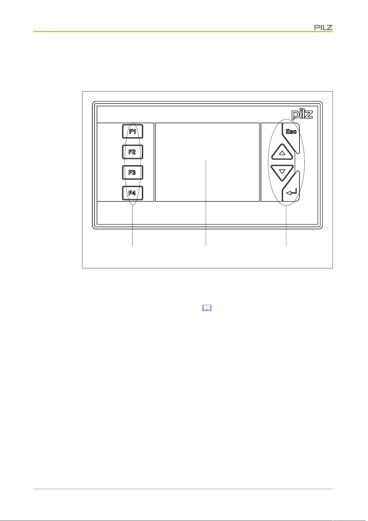
2.2 Front view
2.2.1 PMI 509
Fig.: Front view PMI 509
Legende
[1] F1 ... F4 (function keys)
[2]
Touchscreen (see Technical details [ 45])
[3] ESC, ENTER, cursor up, cursor down
The key allocation is predefined by the operating system, the configuration can be changed
as desired.
Operating Manual PMI 5
1002241-EN-07
8
Page 9
Overview
[1]
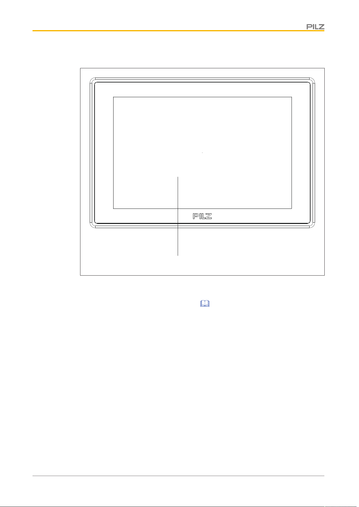
2.2.2 PMI 515/PMI 516/PMI 518/PMI 526/PMI 531/PMI 538
Fig.: Front view of PMI 515/PMI 516/PMI 518/PMI 526/PMI 531/PMI 538
Legende
[1]
Touchscreen (see Technical Details) [ 45]
2.3 Scope of supply
PMI 509
} Operator terminal
} 2 retaining clamps
} Connector plug for power supply
} Projection stands
} Device documentation on CD/DVD
PMI 515
} Operator terminal
} Cover plate
} Connector plug for power supply
} Projection stands
} Device documentation on CD/DVD
Operating Manual PMI 5
1002241-EN-07
9
Page 10

Overview
PMI 516/PMI 518/PMI 526/PMI 531/ PMI 538
} Operator terminal
} Retaining clamps
} Connector plug for power supply
} Projection stands
} Device documentation on CD/DVD
Operating Manual PMI 5
1002241-EN-07
10
Page 11
Safety
3 Safety
3.1 Intended use
This device is used to operate and monitor technical processes.
The PMI offers the possibility of installing software from third-party suppliers. Pilz GmbH &
Co. KG accepts no liability for any damages, nor does it provide support or any guarantee
for the functional efficiency of the installed software.
INFORMATION
Ensure that the graphics software is suitable for the ARMV4i processor type
and the Windows CE 6.0 embedded operating system.
CAUTION!
The unit is not designed for use in applications with stringent safety requirements (e.g. E-STOP).
The following is deemed improper use in particular:
} Any component, technical or electrical modification to the product
} Use of the product outside the areas described in this manual
} Use of the product outside the technical details (see Technical details [ 45]).
NOTICE
EMC-compliant electrical installation
The product is designed for use in an industrial environment. The product
may cause interference if installed in other environments. If installed in other
environments, measures should be taken to comply with the applicable
standards and directives for the respective installation site with regard to interference.
Operating Manual PMI 5
1002241-EN-07
11
Page 12

Safety
3.2 Safety regulations
3.2.1 Use of qualified personnel
The products may only be assembled, installed, programmed, commissioned, operated,
maintained and decommissioned by competent persons.
A competent person is someone who, because of their training, experience and current professional activity, has the specialist knowledge required to test, assess and operate the
work equipment, devices, systems, plant and machinery in accordance with the general
standards and guidelines for safety technology.
It is the company’s responsibility only to employ personnel who:
} Are familiar with the basic regulations concerning health and safety / accident preven-
tion
} Have read and understood the information provided in this description under "Safety"
} And have a good knowledge of the generic and specialist standards applicable to the
specific application.
3.2.2 Warranty and liability
All claims to warranty and liability will be rendered invalid if
} The product was used contrary to the purpose for which it is intended
} Damage can be attributed to not having followed the guidelines in the manual
} Operating personnel are not suitably qualified
} Any type of modification has been made (e.g. exchanging components on the PCB
boards, soldering work etc.).
3.2.3 Disposal
} When decommissioning, please comply with local regulations regarding the disposal of
electronic devices (e.g. Electrical and Electronic Equipment Act).
3.3 Unit-specific safety regulations
Before you install or commission the system, you should refer to any guidelines laid down
by the control manufacturer or operator.
3.3.1 Installation site
} Do not position PMI close to highly flammable materials.
} When installing the unit within a control cabinet, you must ensure the ventilation slots
are not obstructed, otherwise the unit could be damaged through overheating.
} Protect the unit from direct sunlight and dust.
Operating Manual PMI 5
1002241-EN-07
12
Page 13
Safety
3.3.2 Measures to protect against interference
} If necessary, use bulkhead separators to protect the unit from sources of interference.
} Inductive loads within the environment (e.g. contactor, relay and solenoid valve coils)
should be wired using suppression elements (e.g. RC elements). This is particularly important if these inductive loads are fed from the same supply.
} The power cables and the data cables should be physically separated from each other
in their own conduits (recommended minimum distance: 10 cm/3.94"). This will avoid inductive and capacitive interference.
} The prescribed earth point for the functional earth guarantees compliance with
noise immunity requirements.
Connect the functional earth to the central earth point in star form. A cable cross section of at least 1.5mm² should be used for the connection. Connections should be kept
as short as possible.
3.3.3 Supply voltage
} The supply voltage must be +24VDC
CAUTION!
Safe electrical isolation must be ensured for the external power supply generating the 24V voltage supply. Failure to do so could result in electric
shock. Power supplies must conform to DINVDE0551/EN60742 and
EN50178.
3.3.4 Operation
} Plan the system correctly to ensure that a communication error between the PMI and
the host computer does not cause a malfunction.
} Do not operate the touchscreen interface using hard or heavy objects or apply excess-
ive pressure.
} The maximum ambient temperature must not be exceeded when using the unit.
} Do not pour liquids over the unit or insert any objects into the unit.
} When in storage and during operation, protect the unit from vibration and shock.
} Avoid using chemicals close to the system.
3.3.5 Maintenance
} Do not use thinners or organic solvents to clean the unit and touchscreen surface.
Further information on care and maintenance of the touchscreen can be found in the
chapter "Care and Maintenance".
Operating Manual PMI 5
1002241-EN-07
NOTICE
The touchscreen surface is not abrasion resistant; if it is dirty, please clean
with care and do not apply heavy pressure.
13
Page 14
Function description
[1]
[5] [6] [7]
[8]
[2]
[3] [4]
4 Function description
4.1 Features
The operator terminal has a memory in which graphics display software can be installed.
With the help of this software, processes can be shown on the display and directly influenced via the touchscreen. An Ethernet interface is available for the transfer of data, e.g.
diagnostic data, and for communication with other subscribers.
The PMI 509 has additional buttons which can be used to control special functions within
an application.
The device is fitted with a real-time clock that is battery-buffered, so allowing it to run for 90
days without an external power supply. The battery is automatically charged during normal
operation by the power supply for the device.
4.2 Unit views
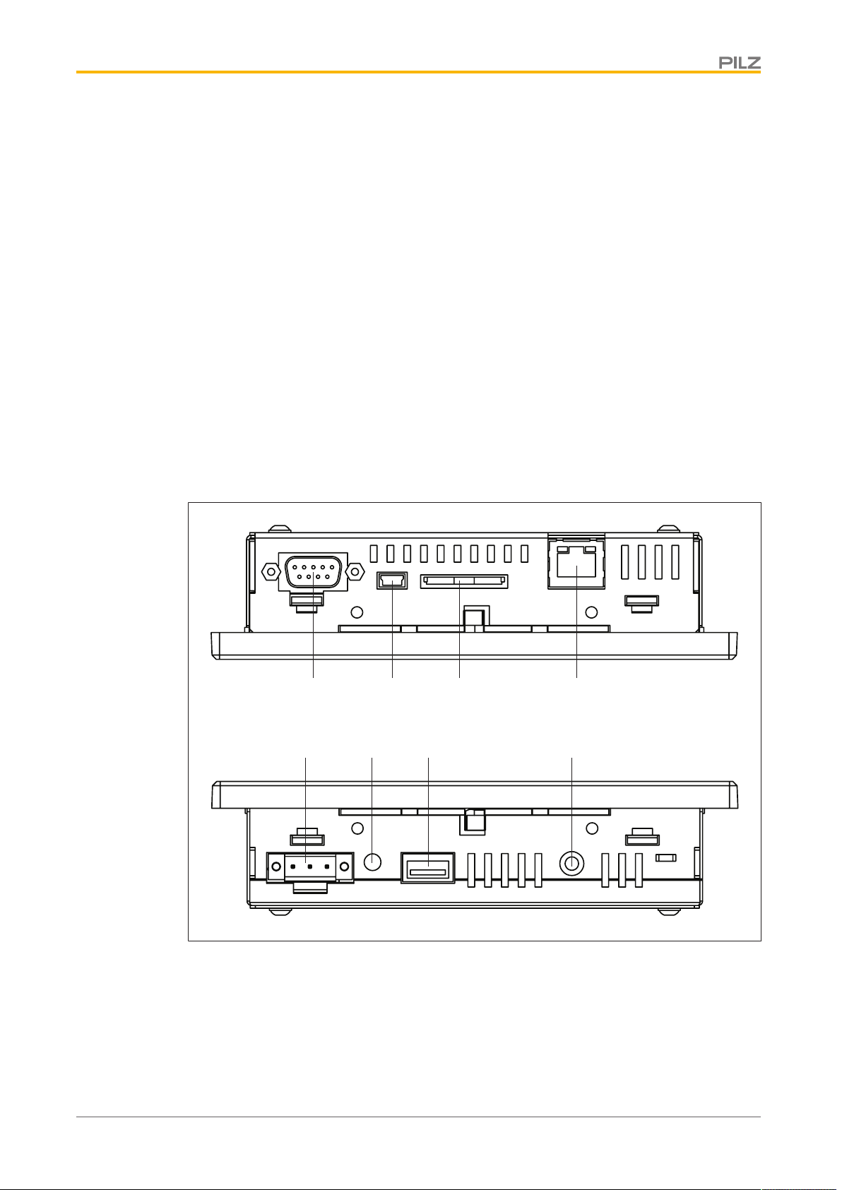
4.2.1 PMI 509
Operating Manual PMI 5
1002241-EN-07
Fig.: Top: plan view of PMI 509, Bottom: view of PMI 509 from below
Legende
[1] Serial interface COM1 (RS232)
[2] USB Slave
[3] SD/SDHC card
[4] Ethernet interface (100 BaseTX)
14
Page 15
Function description
[1]
[5] [6] [7]
[8]
[2]
[3] [4]
[5] Supply voltage +24 VDC
[6] Audio interface LINE OUT
[7] USB Host
[8] Functional earth
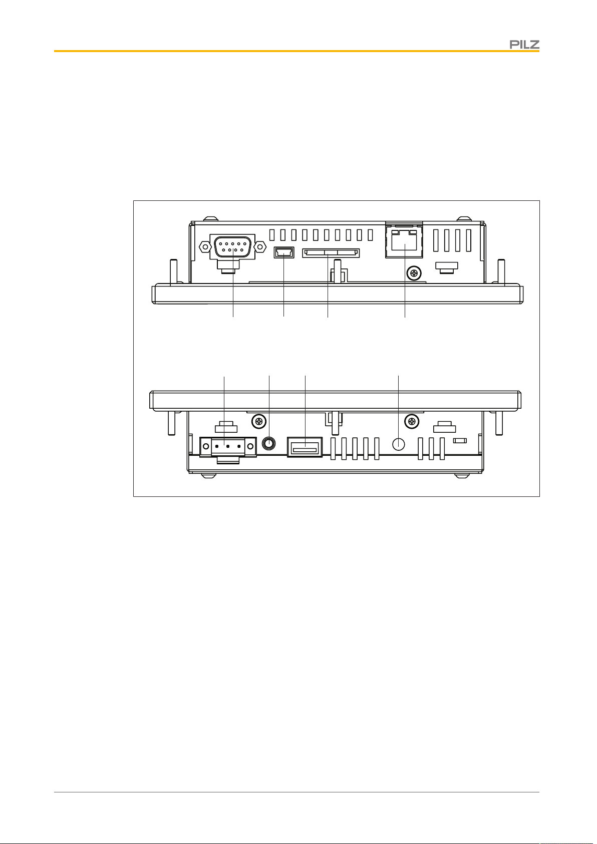
4.2.2 PMI 515
Fig.: Top: plan view of PMI 515, Bottom: view of PMI 515 from below
Legende
[1] Serial interface COM1 (RS232)
[2] USB Slave
[3] SD/SDHC card
[4] Ethernet interface (100 BaseTX)
[5] Supply voltage +24 VDC
[6] Audio interface LINE OUT
[7] USB Host
[8] Functional earth
Operating Manual PMI 5
1002241-EN-07
15
Page 16

Function description
[1]
[4]
[2]
[3]
[5]
[6]
[7]
[8] [9]
4.2.3 PMI 516/PMI 518/PMI 526/PMI 531/ PMI 538
Fig.: Top: plan view of PMI 516/PMI 518/PMI 526/PMI 531/PMI 538, Bottom: view of PMI 516/PMI
518/PMI 526/PMI 531/PMI 538 from below
Legende
[1] Audio interface LINE OUT
[2] SD/SDHC card
[3] Ethernet interface (100 BaseTX)
[4] Supply voltage +24 VDC
[5] Serial interface COM1 (RS232)
[6] USB Slave
[7] USB Host 1
[8] USB Host 2
[9] Functional earth
Operating Manual PMI 5
1002241-EN-07
16
Page 17

Installation
5 Installation
5.1 Safety
NOTICE
Damage due to electrostatic discharge!
Electrostatic discharge can damage components. Ensure against discharge
before touching the product, e.g. by touching an earthed, conductive surface or by wearing an earthed armband.
Please read the safety guidelines before assembling and installing the PMI.
Before you install or commission the system, you should refer to any guidelines laid down
by the plant manufacturer or operator.
5.1.1 Installation site and unit surroundings
} Keep as large a distance as possible between the system and any electromagnetic
fields, particularly when frequency converters are nearby.
} To avoid the build-up of heat, a distance of 10 cm/3.94" should be kept free all round
the unit.
} Protect the system from direct sunlight and dust
} Do not use chemicals close to the system.
} Ensure the maximum ambient and operating temperatures are not exceeded.
} Ensure that neither liquids nor objects can enter the unit at any time.
} Do not position the system close to flammable materials.
Operating Manual PMI 5
1002241-EN-07
17
Page 18

Installation
Front view Side viewPlan view
Mounting cutout
5.2 Dimensions PMI 509
Fig.: Dimensions PMI 509
b1/mm
h1/mm
b2/mm
h2/mm
h3*/mm
t*/mm
b3/mm
h4/mm
h*/t* = Dimensions without connections
Allow extra for hardware connections!
PMI 509
157 (6.181")
87 (3.425")
135.9 (5.350")
8 (0.314")
66 (2.598")
32 (1.259")
138 + 1 (5.433" + 0.039")
68 + 0.7 (2.677" + 0.027")
Operating Manual PMI 5
1002241-EN-07
18
Page 19

Installation
Front view Plan view Side view
Mounting cutout
5.3 Dimensions PMI 515
Fig.: Dimensions PMI 515
PMI 515
b1/mm
h1/mm
b2/mm
h2*/mm
t*/mm
b3/mm
h3/mm
170 (6.693")
144 (5.669")
135.9 (5.350")
66 (2.598")
32 (1.259")
154 + 1 (6.063" + 0.039")
128 + 1 (5.039" + 0.039")
h*/t* = Dimensions without connections
Allow extra for hardware connections!
Operating Manual PMI 5
1002241-EN-07
19
Page 20

Installation
Front view Plan view Side view
Mounting cutout
5.4 Dimensions PMI 516/PMI 518/PMI 526/PMI 531/PMI 538
Fig.: Dimensions PMI 516/PMI 518/PMI 526/PMI 531/PMI 538
PMI 516 PMI 518 PMI 526 PMI 531 PMI 538
b1/mm
h1/mm
b2/mm
h2*/mm
t*/mm
b3/mm
h3/mm
212 (8.346")
165 (6.496")
195 (7.677")
146 (5.748")
56.5 (2.224")
197 + 1 (7.756"
+ 0.039")
148 + 1 (5.827"
+ 0.039")
232 (9.134")
160 (6.299")
215 (8.465")
141 (5.551")
56.5 (2.224")
217 + 1 (8.543"
+ 0.039")
143 + 1 (5.63" +
0.039")
317 (12.480")
243 (9.567")
300 (11.811")
221 (8.701")
56.5 (2.224")
302 + 1 (11.89"
+ 0.039")
223 + 1 (8.78" +
0.039")
h*/t* = Dimensions without connections
Allow extra for hardware connections!
352 (13.858")
276 (10.866")
337 (13.268")
252.4 (9.937")
57.3 (2.255")
339 + 1 (13.346"
+ 0.039")
255 + 1 (10.039"
+ 0.039")
412 (16.22")
332 (13.071")
390 (15.354")
308.4 (12.142")
57.3 (2.255")
393 + 1 (15.472"
+ 0.039")
311 + 1 (12.244"
+ 0.039")
Operating Manual PMI 5
1002241-EN-07
20
Page 21

Installation
5.5 Installing the unit
When installing the unit, please note the following:
} For stability reasons, the front panel, console or control cabinet should have a wall
thickness of at least 2.5mm.
} To avoid a build-up of heat, a distance of a 10cm/3.94" should be kept free all round
the system.
} Ensure the information given for the ambient and operating temperatures in the tech-
nical details is observed.
} IP65 protection can only be guaranteed when
– the fixing screws are sufficiently tightened (min. 0.2Nm).
– the gasket is not damaged.
– the wall thickness is at least 2.5mm.
} Protect the system against falling down, i.e. ensure that the fixing screws are firmly
tightened.
5.6 PMI 509 Installation
Fig.: PMI 509 Installation
Operating Manual PMI 5
1002241-EN-07
NOTICE
The torque setting for the fixing screws may not exceed 0.3 Nm.
21
Page 22

Installation
5.7 PMI 515 Installation
Fig.: PMI 515 Installation
Operating Manual PMI 5
1002241-EN-07
22
Page 23

Installation
5.8 Installing the PMI 516/PMI 518/PMI 526/PMI 531/PMI 538
Fig.: Installing the PMI516/PMI 518/PMI 526/PMI 531/PMI 538
Operating Manual PMI 5
1002241-EN-07
23
Page 24

Wiring
6 Wiring
6.1 General wiring guidelines
} Electrical or electronic components which could cause interference (contactors, thyris-
tors, relay coils and solenoid valve coils) should be physically separate from data lines.
We recommend you use a sheet metal (MU metal) bulkhead between both areas.
} Data lines and power lines should be laid separately to avoid capacitive and inductive
interference (recommended minimum distance = 10 cm/3.94").
} Screened data lines should also be laid in a different cable duct to the main power
lines.
} Power lines should be as short as possible
} Power lines should be twisted pair cables.
} We recommend a max. length of 2 m for the USB cable, to guarantee reliable data
transfer.
} UL requirement: only use copper wiring that will withstand 60/75°C for the supply
voltage; maximum torque setting: 0.5-0.6 Nm.
6.1.1 Shielding
} Connect the power cable shield with low impedance to earth.
} Use only shielded data lines.
} For high-frequency reasons, we recommend that the shielding on the data line cable
(RS 232 cable) is earthed on both sides. If you are using longer cables and there is the
possibility of transient currents, we recommend one of the following methods:
– Use equipotential bonding conductors
– Use electrical isolation
} Connect data line shields to a bus bar.
} Make the connection of the bus bar to the control cabinet/system as short and with as
low impedance as possible.
} Fasten the braided shield to the shield bar over as large a surface area as possible
(e.g. with metal hose clips or PUK cable clips).
6.1.2 Measures to protect against interference voltages
} Wire-up inductive loads (e.g. contactor coils, relay coils and solenoid valve coils) using
suppression elements (e.g. RC networks). This is particularly important if these inductive loads are very close to the power supply or are fed from the same supply.
} If strong magnetic fields are present, we recommend you use a bulkhead separator, i.e.
metal sheet (MU-metal).
Operating Manual PMI 5
1002241-EN-07
24
Page 25

Wiring
1 2 3
6.2 Connecting the Unit
6.2.1 Supply voltage
The connection for the 24VDC supply is located on the side of the housing.
Fig.: Layout of supply voltage connector
} 1: Functional earth
} 2: 0 V
} 3: + 24 VDC
UL requirement: Use a 24 VDC power supply (isolating source). Connect a max. 5 A fuse
between the power supply and PMI.
Operating Manual PMI 5
1002241-EN-07
25
Page 26

Wiring
[1]
[2]
[3]
[4] [5]
[3]
[4]
[5]
[6]
6.2.2 Connection example
Fig.: Connection example
Legende
[1] Earth star point of the unit or control cabinet
[2] Earth bus bar
[3] Supply voltage
[4] Functional earthing terminal (electronic)
[5] Functional earthing bolts (housing)
[6] Data line shield
0V and are connected internally.
Operating Manual PMI 5
1002241-EN-07
26
Page 27

Wiring
GND
n.c.
TxD
RxD
n.c.
n.c.
CTS
RTS
n.c.
n.c. = Not
connected
6.2.3 Interfaces
Pin assignment of RS232 interface
(COM1)
Fig.: Pin assignment of RS232 interface, Sub-D connector, 9-pin
Operating Manual PMI 5
1002241-EN-07
27
Page 28

Putting into Service
7 Putting into Service
Behaviour after switch-on
There may be a delay of several seconds between switch-on and the unit being ready for
operation.
The application software can then be installed and started.
7.1 Activating the setup
If you do not press the SETUP button within 2 seconds, the "PMIStart.cmd" script file will be
run. "PMIStart.cmd" is a batch file which is processed step by step.
Fig.: Activating Setup
7.2 Control Panel
All system settings can be made from the Control Panel of Windows Embedded CE 6.0.
Special features and device-specific settings are described in the following.
Operating Manual PMI 5
1002241-EN-07
28
Page 29

Putting into Service
7.2.1 Backup and restore
Program which you can use to save or restore an entire directory structure.
7.2.2 Password settings
Assign a password for the Control Panel to protect the settings in this area. Two levels can
be protected with different passwords.
Level 1: Master Control panel password
The whole Control Panel can be protected with a password.
Defining a password: Enter a password. Enter the password again under "Confirm password".
Change password: Same as for defining a password
Delete password: Deselect Ask for master password ….
If you select Ask for master password ..., then the system will request that the master password is entered before the Control Panel opens.
Timeout
If an incorrect password is entered three times or no valid password is entered within the
selected time, then the Control Panel is closed.
Operating Manual PMI 5
1002241-EN-07
29
Page 30

Putting into Service
Level 2: Control panel applets
Individual Control Panel "applets" can be protected with a password.
Add
Add Control Panel "applets" to the password protected area. This area is protected with a
password.
Remove
Remove Control Panel "applets" from the password protected area. This area is not protected with a password.
INFORMATION
Add Password Settings to the password protected area, otherwise the
password you enter will be unprotected and can be changed.
Operating Manual PMI 5
1002241-EN-07
30
Page 31

Putting into Service
Level 3: Network user
Access to the network servers is controlled by a central user.
To change the default settings, follow the instructions below:
User name: Enter a user name
Password: Enter a password for the network user
Confirm password: Enter the new password again
INFORMATION
The ex-works setting for the network user is:
User name: pmiuser
Password: 1234
Operating Manual PMI 5
1002241-EN-07
31
Page 32

Care and Maintenance
8 Care and Maintenance
8.1 Cleaning the touchscreen
Clean the unit's touchscreen at regular intervals. Use a damp cloth to do this.
NOTICE
Make sure the unit is switched off before cleaning it. This prevents you from
accidentally triggering functions when you touch the touchscreen.
Cleaning agents
Only use water and washing-up liquid to dampen the cloth. Never spray the cleaning agent
directly onto the touchscreen - spray it onto the cleaning cloth instead. Never use aggressive solvents or abrasive cleaning agents.
Operating Manual PMI 5
1002241-EN-07
32
Page 33

Attachment
9 Attachment
9.1 Supported Windows components
The devices work with the operating system "Microsoft Windows CE 6.0 Professional", the
following Windows components are supported:
Applications
} Active Sync (Microsoft Windows Mobile Device Center)
} CAB File Installer/Uninstaller
} WordPad
Application and Service Development
} .NET Compact Framework 3.5
} Active Template Library (ATL)
} C Libraries and Runtimes (except OEM Floating Point CRT)
- C++ Runtime Support for Exception Handling and Runtime Type Information
- Full C Runtime
- Standard IO (STDIO)
- Standard IOASCII (STDIO)
- Standard String Functions - ASCII (corestra)
} Component Services (COM and DCOM)
- DCOM
- DCOM Remoting
} Message Queuing (MSMQ)
} OBEX Client
} SOAP Client
} String Safe Utility Function
} XML - MSXML 3.0
- XML Core Services and Document Object Model (DOM)
- XML Error Strings
- XML HTTP
- XML Query Languages (XQL)
- XML Stylesheet Language Transformations (XSLT)
- XML SAX
- XML Minimal Parser
Communication Services and Networking
} Networking General
Operating Manual PMI 5
1002241-EN-07
- Extended DNS Querying and Update (DNSAPI)
- NDIS Packet Capturing DLL
- NDIS User-mode I/O Protocol Driver
- Network Driver Architecture (NDIS)
- Network Utilities (IpConfig, Ping, Route)
33
Page 34

Attachment
- TCP/IP
- It includes support for IP, ARP, ICMP, IGMP, TCP, UDP, name resolution and registration, DHCP.
- Windows Networking API/Redirector (SMB/CIFS)
- Winsock Support
} Networking - Local Area Networking (LAN)
- Wired LAN (802.3, 802.5)
} Networking - Wide Area Networking (WAN)
- Dial Up Networking (RAS/PPP)
- Telephony API (TAPI 2.0)
} Servers
- Core Server Support
- File Server
- File Server (SMB/CIFS)
- FTP Server
- Simple Network Time Protocol (SNTP)
- SNTP Client with DST
- SNTP Server
- Telnet Server
- Web Server (HTTPD)
- Active Server Pages (ASP) Support
- JScript 5.6
- VBScript 5.6
- Web Server Administration ISAPI
- WEBDAV Support
Core OS Services
} System Event Log
} Battery Driver
- Debugging Tools
- Toolhelp API
} Device Manager
} Display Support
} Kernel Functionality
- Fiber API
- Format Message API
- Format Message API - System Error Messages
- Memory Mapped Files
- Message Queue - Point-to-Point
- Target Control Support (Shell.exe)
} UI based Notification
} Notification LED Support
} Power Management (Full)
} Serial Port Support
} UI Proxy for Kernerl-Mode-Drivers
Operating Manual PMI 5
1002241-EN-07
34
Page 35

Attachment
} USB Host Support
- USB Function Driver
- USB Host Driver
- USB Human Input Device (HID) Class Driver
- USB Printer Class Driver
- USB Storage Class Driver
} Windows Embedded CE Driver Development Kit Support Library
File System and Data Store
} Compression
} Database Support (CEDB Database Engine)
- CEDB Database Engine
} File and Database Replication (Bit-based)
} File System - Internal (RAM and ROM File System)
} Registry Storage (Hive-based Registry)
} Storage Manager
- CD/UDFS File System
- exFAT File System
- FAT File System
- Partition Driver
- Release Directory File System
- Storage Manager Control Panel Applet
- Transaction-Safe FAT File System (TFAT)
} System Passwort
Fonts
The following fonts have been preinstalled:
} Arial
} Comic Sans MS
} Courier New
} Georgia
} Impact
} Kino
} MSLogo
} Symbol
} Tahoma
} Times New Roman
} Trebuchet MS
} Verdana
} Webdings
} Webding
} Wingding
Operating Manual PMI 5
1002241-EN-07
35
Page 36

Attachment
INFORMATION
TTF formats can be post-installed.
– Option 1:
Use the Windows CE Shell command "fontreg" (see Windows CE
Shell command- Pilz extensions)
Syntax: fontreg.exe FONTNAME [/h] [/H] [/?] [/help]
– Option 2:
Create a new "Fonts" folder under "Flash/Windows" and save all TTF
fonts under "Flash/Windows/Fonts". Please note that after each reboot the complete content of "Flash/Windows" is copied to the "Windows " folder of the RAM.
Graphics and multimedia formats
} Audio (Waveform Audio)
} Graphics
- Alphablend API (GDI version)
- DirectDraw
- Gradient Fill Support
- Imaging
- Still Imagine Codec Support (Encode and Decode)
- Still Image Decoders
- BMP
- GIF
- ICO
- JPG
- PNG
- TIFF
- Still Image Encoders
- BMP
- GIF
- JPG
- PNG
- TIFF
International
} Input Method Manager (IMM)
} Locale Service (National Language Support (NLS))
} Locale Specific Support (English US - US Keyboard)
Operating Manual PMI 5
1002241-EN-07
36
Page 37

Attachment
Internet Client Services
} Browser Application
- Internet Explorer 6.0 for Windows Embedded CE - Standard Components
- Internet Explorer 6.0 Sample Browser
} Internet Explorer 6.0 for Windows Embedded CE Components
- Internet Explorer Browser Control Host
- Internet Explorer HTML/DHTML API
- Internet Explorer Plug-in Image Decoder API
- Internet Explorer PNG Image Decoder
- MSHTML Data Binding
- Internet Explorer Multi-Language Base API
- URL Moniker Service
- Windows Internet Services
- XML Data Islands
- XML MIME Viewer
- Internet Option Control Panel
- Scripting
- JScript 5.6
- Script Authoring (Jscript)
- Script Encode (Jscript)
- VBScript 5.6
- MsgBox and InputBox support
- Script Authoring
- Script Encode (VBScript)
Security
} Authentication Services (SSPI)
- NTLM
- Schannel (SSL/TLS)
} Credential Manager
} Cryptography Service (CryptoAPI 1.0) with High Encryption Provider
- Certificates (CryptoAPI 2.0)
Shell and User Interface
} Graphics, Windowing and Events
- Minimal GDI Configuration
- Minimal GWES Configuration
- Minimal Input Configuration
- Minimal Window Manager Configuration
} Shell
- AYGShell API Set
- Command Shell
- Command Processor
- Console Window
- Graphical Shell - Standard Shell
Operating Manual PMI 5
1002241-EN-07
37
Page 38

Attachment
} User Interface
- Common Controls
- Common Control
- Common Dialog Support
- Control Panel Applets
- Customizeable UI
- Windows XP-like Sample Skin
- Gesture
- Gesture Animation Support
- Gesture Support for Win32 Controls
- Single-Touch Gesture Recognition
- Mouse
- Network User Interface
- Software Input Panel
- Software-based Input Panel (SIP)
- SIP for Large Screens
- SIP for Small Screens
- Software-based Input Panel Drivers
- Touch Screen (Stylus)
Windows Embedded CE Error Reporting
} Error Report Generator
} Error Report Transfer Driver
9.2 Windows CE Shell commands
Commands Shell parameters
Command Description
"/C" Execute command and exit "Command processor shell".
"/K" Execute command, "Command processor shell" remains active
"string" Command that is to be executed
Syntax of the command line
Command Description
"COMMAND" Command name
"OPTIONS" Command specification
">" Forward the output text to a file
Operating Manual PMI 5
1002241-EN-07
"2>" Forward the output fault to a file
">>" Attach the output text to a file
"2>>" Attach the output fault to a file
"<" reads input text from a file
"&" separates a command or several commands
38
Page 39

Attachment
Command Description
"|" separates a command or several commands and sends the output of
a command as input for the command that follows
"file1" Name of the file that includes the output
"file2" Name of the file that includes the input
List of all possible Shell commands
Command Description
"ATTRIB" shows or changes the properties of a file
"CALL" calls up a batch program from another batch program
"CHDIR, CD" shows the name of the current directory or changes the current direct-
ory
"CLS" deletes the screen
"COPY" copies one or several files to a different directory
"DATE" shows or sets the date
"DIR" shows the files and subdirectories that a directory includes
"ECHO [mes-
shows a message or activates/deactivates the echo
sage] [on| off] "
"ERASE, DEL" deletes a file or several files
"EXIT" exits "command processor shell"
"GOTO" causes the "command processor" to jump into a highlighted line in a
batch program
"HELP" shows a list of available commands
"IF" executes conditional processing in a batch program
"MKDIR, MD" creates a directory
"MOVE" moves files from one directory to another
"net" executes network-related operations
"PATH" shows or sets a search path for executable files
"PAUSE" interrupts the processing of a batch program
"PROMPT" changes the prompt for the "command processor"
"PWD" prints the current directory path
"REM" saves comments to a batch file
Operating Manual PMI 5
1002241-EN-07
"RENAME, REN" changes the name of one or several files
"RMDIR, RD" deletes a directory
"SET" sets or removes an environment variable or shows the values of all
environment variables
"SHIFT" changes the position of variable parameters in a batch file
"START" starts a separate window that executes a certain application or com-
mand
"TIME" shows the system time or sets it
39
Page 40

Attachment
Command Description
"TITLE" sets the title of the "command processor" window
"TYPE" shows the content of a text file or several text files
9.3 Windows CE Shell commands - Pilz expansions
INFORMATION
You can use the command "/?" to call up the help. There you find more information on the individual commands.
Common parameters
Command Description
"/h" shows the help
"/H" shows the help
"/?" shows the help
"/help" shows the help
fontreg Command for registering additional TTF fonts on the device
Syntax: fontreg FONTNAME
Parameter Description
FONTNAME can include placeholders, e.g. \*.ttf; when "FONT-
NAME" is a directory, all the fonts are registered in
the directory.
format Command for formatting a removable data medium for use with Win-
dows CE
Syntax: format <volume> [/Q] [/A size] [/FS <File system>]
Parameter Description
/FS determines the file system (FAT12, FAT16, FAT32,
or exFAT)
/Q performs quick formatting
/LLF performs formatting with a low formatting rate
/PART creates a standard partition after formatting with a
low formatting rate
/A overwrites the standard sizes of memory allocation
/T creates a TFAT format
/Y Confirmation
Operating Manual PMI 5
1002241-EN-07
40
Page 41

Attachment
hostetc Administration of host name assignment to the IP address
Syntax: hostetc [/add] [/ipv4 <ip string> ] <hostname>
Parameter Description
/add adds a new host
/delete deletes a host
/list shows all hosts
/a creates an Alias name (e. g. -a alias1,alias2)
/ipv4 IP-String v4
/ipv6 IP-String v6
/t Period of validity (example:
\"1985-04-12T23:20:50.52Z\", rfc 3339)
kill Command used to force the completion of a process
Syntax: kill [EXENAME] /[PID]
Parameter Description
EXENAME completes the process via the process name (e.g.
kill pnotepad.exe)
/PID completes the process via the PID hexadecimal
format (e.g. kill /fa00ce)
pnotepad Command use to start a simple text editor
Syntax: pnotepad file
Parameter Description
file after starting the text editor a file is opened
ps shows all the active processes
Syntax: ps
reboot Command used to restarting the unit
Syntax: reboot <sec>
Parameter Description
<sec> Waiting period in seconds before the device is re-
started.
regedit Command used to start the registration editor
Syntax: regedit
regerase Command used to delete the present registration of the device; in the
next boot process the device uses the default registration
Syntax: regerase [-r]
Parameter Description
-r forces a reboot process
Operating Manual PMI 5
1002241-EN-07
41
Page 42

Attachment
regexp Commend used to export a registration key including subkeys to a file
(*.reg)
Syntax: regexp /r <BaseKey> /f <OutFile> [/c] [ALL]
Parameter Description
/r <BaseKey> Registration key that is to be exported
/f <OutFile> Name of the target file
/c converts REG_MUI_SZ to REG_SZ
/ALL Parameter used to export the whole registration to
a file (*.reg)
regimp Command used to import a registration file (*.reg)
Syntax: regimp <InFile> [/temp] [/info]
Parameter Description
<InFile> File name
/temp temporarily saved, the present registration is not
overwritten
/info Status information on the success/failure of the ac-
tion
regsave Command used to permanently save the current registration
Syntax: regsave
regsvrce Command used to register ActiveX module (*.ocx, *.dll)
Syntax: RegsvrCE [/u] [/n] [/s] [/i[:cmdline]] dllname
Parameter Description
/u Deregisters the server
/n "DllRegisterServer" is not called up, the parameter
must be used with "/i"
/s suppresses messages on the display
/i <cmdline> transmits an optional command line (cmdline) to
DllInstall; when "/i" is combined with "/u", DllUnin-
stall is executed
dllname DLL name
screenshot Command used to print a screenshot or to save a file
Syntax: screenshot -p <port> -d <devicename> -x <filename> -f <formsize> -o [p]ortrait [l]andscape -q [d]raft, [h]igh -s <scalefactor> -c
[c]olor,[m]ono -n <copies>
Parameter Description
-p <port> Printer port
-d <devicename> Printer name
-x <filename> Save screenshot as a file
-f <formsize> Paper size (A4, B5, Legal and Letter)
-o [p] / -o [l] Print orientation portrait / landscape
-q [d] / -q[h] Print quality draft / high
-s <scalefactor> Scaling, format: 1.2 (e.g. 0.5, 2.0,..)
-c[c] /- c[m] Colour (c) / black and white (m)
Operating Manual PMI 5
1002241-EN-07
42
Page 43

Attachment
-n <Copies> Number of copies
sleep Command used to insert a waiting time between to operations (sleep
mode);
Syntax: sleep <ms>
Parameter Description
<ms> Waiting time in milliseconds
usrmgr Command used to manage network subscribers
Syntax: usrmgr [-a|-d|-l] [<user name> [<password>]] -gn -gd -gl -gm -
gat -grf
Parameter Description
-a <user name>
Add or update network subscriber
<password>
-d <user name> Remove network subscriber
-l show all network subscribers
-gn <group name> add new group
-gd <group name> delete group
-hl show all groups
-gm show group members
-gat <group
add group member
name> <user
name>
-grf <group name>
delete group member
<user name>
ver Command used to show information on the device
Syntax: ver [/d] [/a] [/hw /p /o /l /s /r /c]
Parameter Description
/d Data mode, display without description, e.g.:
..
PMI 515
10000007
264515
..
/a show all information
/hw outputs the hardware version
/p outputs the processor type
/o outputs the build version of the operating system
/l outputs the bootloader version
/t outputs the device type
/s outputs the serial number
/r outputs the order number
/c outputs the chip set version
Operating Manual PMI 5
1002241-EN-07
43
Page 44

Attachment
xcopy Command used to copy files and directory structures
Syntax: xcopy [-h | -y | -g | -s | -x | -t <title>] <sourcedir> <targetdir>
Parameter Description
-y Messages are suppressed
-g Use dialog windows
-s Start copying automatically, only makes sense with
-g
-x End copy dialog automatically, only makes sense
with -g
-t Set window title (default setting: xcopy), only
makes sense with -g
-c Delete target directory first
<SourceDir> absolute path of the source directory
<TargetDir> absolute path of the target directory
Operating Manual PMI 5
1002241-EN-07
44
Page 45

Technical details
10 Technical details
Order no. 264509 – 264518
See below for more order numbers
General 264509 264515 264516 264518
CE, EAC (Euras-
Approvals
Electrical data 264509 264515 264516 264518
Supply voltage
Voltage 24 V 24 V 24 V 24 V
Kind DC DC DC DC
Voltage tolerance -15 %/+20 % -15 %/+20 % -15 %/+20 % -15 %/+20 %
Output of external
power supply
(DC) 2,5 W 3,6 W 6,5 W 5,8 W
Display 264509 264515 264516 264518
Display type TFT TFT TFT TFT
Display diagonal 8,9 cm 14,7 cm 16 cm 18 cm
Display resolution 320 x 240 320 x 240 640 x 480 800 x 480
Display colour depth 65536 65536 65536 65536
Touchscreen Resistive Resistive Resistive Resistive
Operating elements 264509 264515 264516 264518
Keyboard type Membrane keypad
Number of keys 8 – – –
Electrical life 1,000,000 cycles
CPU 264509 264515 264516 264518
Processor type RISC processor RISC processor RISC processor RISC processor
Processor clock
speed 1 GHz 1 GHz 1 GHz 1 GHz
Working memory
(RAM) 256 MB 256 MB 256 MB 256 MB
Program memory
(Flash) 512 MB 512 MB 512 MB 512 MB
Real-time clock yes yes yes yes
Removable data
medium
Type SD card SD card SD card SD card
USB interface 264509 264515 264516 264518
Number of USB
Hosts 1 1 2 2
Number of USB
Slaves 1 1 1 1
Ethernet interface 264509 264515 264516 264518
Number 1 1 1 1
ian), cULus Listed
with snap dome – – –
264509 264515 264516 264518
CE, EAC (Eurasian), cULus Listed
– – –
CE, EAC (Eurasian), cULus Listed
CE, EAC (Eurasian), cULus Listed
Operating Manual PMI 5
1002241-EN-07
45
Page 46

Technical details
Serial interface 264509 264515 264516 264518
Number of RS232
interfaces 1 1 1 1
Audio interfaces 264509 264515 264516 264518
Number 1 1 1 1
Environmental data 264509 264515 264516 264518
Ambient temperature
Temperature
range 0 - 50 °C 0 - 50 °C 0 - 50 °C 0 - 50 °C
Storage temperature
In accordance
with the standard EN 60068-2-1/-2 EN 60068-2-1/-2 EN 60068-2-1/-2 EN 60068-2-1/-2
Temperature
range -25 - 60 °C -25 - 60 °C -25 - 60 °C -25 - 60 °C
Climatic suitability
In accordance
with the standard EN 60068-2-78 EN 60068-2-78 EN 60068-2-78 EN 60068-2-78
Humidity 93 % r. h. at 40 °C 93 % r. h. at 40 °C 93 % r. h. at 40 °C 93 % r. h. at 40 °C
Condensation during
operation Not permitted Not permitted Not permitted Not permitted
EMC EN 61000-6-2, EN
61000-6-4
EN 61000-6-2, EN
61000-6-4
EN 61000-6-2, EN
61000-6-4
EN 61000-6-2, EN
61000-6-4
Vibration
In accordance
with the standard EN 60068-2-6 EN 60068-2-6 EN 60068-2-6 EN 60068-2-6
Frequency 10 - 150 Hz 10 - 150 Hz 10 - 150 Hz 10 - 150 Hz
Acceleration 1g 1g 1g 1g
Shock stress
In accordance
with the standard EN 60068-2-27 EN 60068-2-27 EN 60068-2-27 EN 60068-2-27
Acceleration 15g 15g 15g 15g
Duration 11 ms 11 ms 11 ms 11 ms
Protection type
In accordance
with the standard EN 60529 EN 60529 EN 60529 EN 60529
Housing IP64 IP65 IP65 IP65
In accordance
with UL 1,2,5
1,2,5,4/4X indoor
use only
1,2,5,4/4X indoor
use only 1,2,5
Mechanical data 264509 264515 264516 264518
Dimensions
Height 87 mm 144 mm 165 mm 160 mm
Width 157 mm 170 mm 212 mm 232 mm
Depth 40 mm 40 mm 62,5 mm 62,5 mm
Weight 316 g 659 g 1.344 g 1.364 g
Operating Manual PMI 5
1002241-EN-07
46
Page 47

Technical details
Order no. 264526 – 264538
General 264526 264531 264538
Approvals
CE, EAC (Eurasian), cULus Listed
CE, EAC (Eurasian), cULus Listed
CE, EAC (Eurasian), cULus Listed
Electrical data 264526 264531 264538
Supply voltage
Voltage 24 V 24 V 24 V
Kind DC DC DC
Voltage tolerance -15 %/+20 % -15 %/+20 % -15 %/+20 %
Output of external
power supply (DC) 6,3 W 8,9 W 11 W
Display 264526 264531 264538
Display type TFT TFT TFT
Display diagonal 26 cm 31 cm 38 cm
Display resolution 800 x 600 800 x 600 1024 x 768
Display colour depth 65536 65536 65536
Touchscreen Resistive Resistive Resistive
CPU 264526 264531 264538
Processor type RISC processor RISC processor RISC processor
Processor clock speed 1 GHz 1 GHz 1 GHz
Working memory (RAM) 256 MB 256 MB 256 MB
Program memory (Flash) 512 MB 512 MB 512 MB
Real-time clock yes yes yes
Removable data me-
264526 264531 264538
dium
Type SD card SD card SD card
USB interface 264526 264531 264538
Number of USB Hosts 2 2 2
Number of USB Slaves 1 1 1
Ethernet interface 264526 264531 264538
Number 1 1 1
Serial interface 264526 264531 264538
Number of RS232 interfaces 1 1 1
Audio interfaces 264526 264531 264538
Number 1 1 1
Environmental data 264526 264531 264538
Ambient temperature
Temperature range 0 - 50 °C 0 - 50 °C 0 - 50 °C
Storage temperature
In accordance with the
standard EN 60068-2-1/-2 EN 60068-2-1/-2 EN 60068-2-1/-2
Temperature range -25 - 60 °C -25 - 60 °C -25 - 60 °C
Operating Manual PMI 5
1002241-EN-07
47
Page 48

Technical details
Environmental data 264526 264531 264538
Climatic suitability
In accordance with the
standard EN 60068-2-78 EN 60068-2-78 EN 60068-2-78
Humidity 93 % r. h. at 40 °C 93 % r. h. at 40 °C 93 % r. h. at 40 °C
Condensation during operation Not permitted Not permitted Not permitted
EMC EN 61000-6-2, EN
61000-6-4
EN 61000-6-2, EN
61000-6-4
EN 61000-6-2, EN
61000-6-4
Vibration
In accordance with the
standard EN 60068-2-6 EN 60068-2-6 EN 60068-2-6
Frequency 10 - 150 Hz 10 - 150 Hz 10 - 150 Hz
Acceleration 1g 1g 1g
Shock stress
In accordance with the
standard EN 60068-2-27 EN 60068-2-27 EN 60068-2-27
Acceleration 15g 15g 15g
Duration 11 ms 11 ms 11 ms
Protection type
In accordance with the
standard EN 60529 EN 60529 EN 60529
Housing IP65 IP65 IP65
In accordance with UL 1,2,5,4/4X indoor use
only
1,2,5,4/4X indoor use
only
1,2,5,4/4X indoor use
only
Mechanical data 264526 264531 264538
Dimensions
Height 243 mm 276 mm 332 mm
Width 317 mm 352 mm 412 mm
Depth 62,5 mm 63,3 mm 63,3 mm
Weight 2.227 g 2.860 g 4.166 g
Where standards are undated, the 2010-12 latest editions shall apply.
Operating Manual PMI 5
1002241-EN-07
48
Page 49

Order reference
11 Order reference
Product type Features Order No.
PMI 509 Operator terminal, 320 x 240 pixel resolution,
analogue resistive touchscreen, 4 function keys
PMI 515 Operator terminal, 320 x 240 pixel resolution,
analogue resistive touchscreen
PMI 516 Operator terminal, 640 x 480 pixel resolution,
analogue resistive touchscreen
PMI 518 Operator terminal, 800 x 480 pixel resolution,
analogue resistive touchscreen
PMI 526 Operator terminal, 800 x 600 pixel resolution,
analogue resistive touchscreen
PMI 531 Operator terminal, 800 x 600 pixel resolution,
analogue resistive touchscreen
PMI 538 Operator terminal, 1024 x 768 pixel resolution,
analogue resistive touchscreen
264 509
264 515
264 516
264 518
264 526
264 531
264 538
Operating Manual PMI 5
1002241-EN-07
49
Page 50

The Best of
German
En
gineering
Partner of:
Support
Technical support is available from Pilz round the clock.
Americas
Brazil
+55 11 97569-2804
Canada
+1 888-315-PILZ (315-7459)
Mexico
+52 55 5572 1300
USA (toll-free)
+1 877-PILZUSA (745-9872)
Asia
China
+86 21 60880878-216
Japan
+81 45 471-2281
South Korea
+82 31 450 0680
Australia
+61 3 95446300
Europe
Austria
+43 1 7986263-0
Belgium, Luxembourg
+32 9 3217575
France
+33 3 88104000
Germany
+49 711 3409-444
Ireland
+353 21 4804983
Italy
+39 0362 1826711
Scandinavia
+45 74436332
Spain
+34 938497433
Switzerland
+41 62 88979-30
The Netherlands
+31 347 320477
Turkey
+90 216 5775552
United Kingdom
+44 1536 462203
You can reach our
international hotline on:
+49 711 3409-444
support@pilz.com
CMSE
®
, InduraNET p
®
, PAS4000
®
, PAScal
®
, PASconfig
®
, Pilz
®
, PIT
®
, PLID
®
, PMCprimo
®
, PMCprotego
®
, PMCtendo
®
, PMD
®
, PMI
®
, PNOZ
®
, Primo
®
, PSEN
®
, PSS
®
, PVIS
®
, SafetyBUS p
®
,
SafetyEYE
®
, SafetyNET p
®
, THE SPIRIT OF SAFETY
®
are registered and protected trademarks of Pilz GmbH & Co. KG in some countries. We would point out that product features may vary
from the details stated in this document, depending on the status at the time of publication and the scope of the equipment. We accept no responsibility for the validity, accuracy
and entirety of the text and graphics presented in this information. Please contact our Technical Support if you have any questions.
Pilz develops environmentally-friendly products using
ecological materials and energy-saving technologies.
Oces and production facilities are ecologically designed,
environmentally-aware and energy-saving. So Pilz oers
sustainability, plus the security of using energy-ecient
products and environmentally-friendly solutions.
Pilz GmbH & Co. KG
Felix-Wankel-Straße 2
73760 Ostfildern, Germany
Tel.: +49 711 3409-0
Fax: +49 711 3409-133
info@pilz.com
www.pilz.com
100XXXX-DE-0X
0-0-1-3-000, 2015-00 Printed in Germany
© Pilz GmbH & Co. KG, 2015
Back cover
1002241-EN-07, 2016-08 Printed in Germany
© Pilz GmbH & Co. KG, 2015
 Loading...