

Page 1

SERVICE STATION MANUAL
633734 ÷ 633741
MSS ZIP 100 4T
Page 2

SERVICE STATION
MANUAL
MSS ZIP 100 4T
The descriptions and illustrations given in this publication are not binding. While the basic specifications
as described and illustrated in this manual remain unchanged, PIAGGIO-GILERA reserves the right, at
any time and without being required to update this publication beforehand, to make any changes to
components, parts or accessories, which it considers necessary to improve the product or which are
required for manufacturing or construction reasons.
Not all versions/models shown in this publication are available in all countries. The availability of single
models should be checked at the official Piaggio sales network.
"© Copyright 2008 - PIAGGIO & C. S.p.A. Pontedera. All rights reserved. Reproduction of this publication
in whole or in part is prohibited."
PIAGGIO & C. S.p.A. - After sales
V.le Rinaldo Piaggio, 23 - 56025 PONTEDERA (Pi)
Page 3

SERVICE STATION MANUAL
MSS ZIP 100 4T
This service station manual has been drawn up by Piaggio & C. Spa to be used by the workshops of
Piaggio-Gilera dealers. It is assumed that the user of this manual for maintaining and repairing Piaggio
vehicles has a basic knowledge of mechanical principles and vehicle repair technique procedures. Any
significant changes to vehicle characteristics or to specific repair operations will be communicated by
updates to this manual. Nevertheless, completely satisfactory work cannot be carried out without the
necessary equipment and tools. It is therefore advisable to read the sections of this manual relating to
appropriate tools, along with the appropriate tool catalogue.
N.B. Provides key information to make the procedure easier to understand and carry out.
CAUTION Refers to specific procedures to carry out for preventing damages to the vehicle.
WARNING Refers to specific procedures to carry out to prevent injuries to the repairer.
Personal safety Failure to completely observe these instructions will result in serious risk of personal
injury.
Safeguarding the environment Sections marked with this symbol indicate the correct use of the vehicle
to prevent damaging the environment.
Vehicle intactness The incomplete or non-observance of these regulations leads to the risk of serious
damage to the vehicle and sometimes even the invalidity of the guarantee.
Page 4

Page 5

INDEX OF TOPICS
CHARACTERISTICS CHAR
TOOLING TOOL
MAINTENANCE MAIN
TROUBLESHOOTING TROUBL
ELECTRICAL SYSTEM ELE SYS
ENGINE FROM VEHICLE ENG VE
ENGINE ENG
SUSPENSIONS SUSP
BRAKING SYSTEM BRAK SYS
CHASSIS CHAS
PRE-DELIVERY PRE DE
TIME TIME
Page 6

INDEX OF TOPICS
CHARACTERISTICS CHAR
Page 7

Rules
This section describes general safety rules for any maintenance operations performed on the vehicle.
Safety rules
- If work can only be done on the vehicle with the engine running, make sure that the premises are wellventilated, using special extractors if necessary; never let the engine run in an enclosed area. Exhaust
fumes are toxic.
- The battery electrolyte contains sulphuric acid. Protect your eyes, clothes and skin. Sulphuric acid is
highly corrosive; in the event of contact with your eyes or skin, rinse thoroughly with abundant water
and seek immediate medical attention.
- The battery produces hydrogen, a gas that can be highly explosive. Do not smoke and avoid sparks
or flames near the battery, especially when charging it.
- Fuel is highly flammable and it can be explosive given some conditions. Do not smoke in the working
area, and avoid naked flames or sparks.
- Clean the brake pads in a well-ventilated area, directing the jet of compressed air in such a way that
you do not breathe in the dust produced by the wear of the friction material. Even though the latter
contains no asbestos, inhaling dust is harmful.
Maintenance rules
- Use original PIAGGIO spare parts and lubricants recommended by the Manufacturer. Non-original or
non-conforming spare parts may damage the vehicle.
- Use only the appropriate tools designed for this vehicle.
- Always use new gaskets, sealing rings and split pins upon refitting.
- After removal, clean the components using non-flammable or low flash-point solvents. Lubricate all
the work surfaces, except tapered couplings, before refitting these parts.
- After refitting, make sure that all the components have been installed correctly and work properly.
- For removal, overhaul and refit operations use only tools with metric measures. Metric bolts, nuts and
screws are not interchangeable with coupling members with English measurement. Using unsuitable
coupling members and tools may damage the scooter.
- When carrying out maintenance operations on the vehicle that involve the electrical system, make
sure the electric connections have been made properly, particularly the ground and battery connections.
MSS ZIP 100 4T Characteristics
CHAR - 7
Page 8

Vehicle identification
VEHICLE IDENTIFICATION
Specification Desc./Quantity
Engine prefix M252M ÷ 1001
Chassis prefix LEMM25200 ÷ 1001
Dimensions and mass
WEIGHTS AND DIMENSIONS
Specification
Desc./Quantity
Total and dry weight 89 ± 3 kg
Width 680 mm
Length 1700 mm
Wheelbase 1200 mm
Height 1060 mm
Engine
ENGINE
Specification
Desc./Quantity
Type single-cylinder, four-stroke
Bore 50 mm
Stroke 49 mm
Cubic capacity 96.21 cc
Compression ratio 10.5 ÷ 11.5 : 1
Timing system single overhead camshaft, two valves, driven by a chain to the
left side.
Depression carburettor KEIHIN CVK
CO adjustment 3.2% ± 0.5
Engine idle speed (100 cc) ~ 1500 ± 150 rpm
Air filter sponge impregnated with a mixture 50% oil (Selenia Air Filter
Oil) and 50% unleaded petrol.
Starting system electric starter/kick-starter
Lubrication engine lubrication with lobe pump (inside the crankcase),
chain-driven, and double filter: mesh and centrifugal.
Fuel supply Gravity feed, with unleaded petrol (with a minimum octane rat-
ing of 95) with carburettor.
Max power (to the crankshaft) 4.2 kW (5.7 CV) at 6750 rpm
Maximum torque (to the crankshaft) 6.92 Nm 6000 rpm.
Cooling system with forced air.
Valve clearance (cold engine) intake 0.10 mm
discharge 0.15 mm
Characteristics MSS ZIP 100 4T
CHAR - 8
Page 9

Transmission
TRANSMISSIONS
Specification Desc./Quantity
TRANSMISSION With automatic expandable pulley variator, torque server, V-
belt, automatic clutch, gear reduction unit.
Capacities
CAPACITY
Specification Desc./Quantity
Main and supplementary fuel tank (including ~ 1.2 l reserve)
(100 cc)
~ 7 l
Rear hub (100 cc) approx. 80 cm³
Engine oil approx. 850 cm³ (recommended oil: SELENIA HI SCOOTER 4
Tech)
Electrical system
ELECTRICAL COMPONENTS
Specification
Desc./Quantity
Type of ignition Capacitive discharge type electronic ignition, with incorporated
high voltage coil
Variable ignition advance by microprocessor (before TDC) 15° at 1500 rpm.
22° at 5000 ÷ 6000 rpm.
spark plug Champion RG 4 HC
CHAMPION RG 4 PHP
NGK CR9EB
Fuse (100 cc) 10 A
Generator single-phase alternating current
Frame and suspensions
FRAME
Specification
Desc./Quantity
Type of chassis Welded tubular steel chassis with stamped sheet reinforce-
ments.
Front suspension Mechanical telescopic fork with 30-mm stems.
Front suspension stroke 77 mm
Rear suspension travel 70 mm
Front brake Disc brake (220 mm in diameter) with hydraulic control (lever
on the right side of the handlebar).
Rear brake Drum brake (140 mm in diameter) with expanding shoes, me-
chanically operated
Front tyre size 100/80-10''
Rear tyre size 120/70-10''
Tyre pressure (100 cc) Front wheel: 1.3 bar
Rear wheel: 1.6 ÷ 1.8 bar
Rims made of light alloy:
2.50x10'' (front)
3.00x10'' (rear)
N.B.
CHECK AND ADJUST TYRE PRESSURE WITH TYRES AT AMBIENT TEMPERATURE. REGULATE PRESSURE ACCORDING TO THE WEIGHT OF BOTH RIDER AND ACCESSORIES
MSS ZIP 100 4T Characteristics
CHAR - 9
Page 10

Brakes
BRAKES
Specification Desc./Quantity
Front brake Disc brake (Ø 175 mm) with hydraulic control (lever on the
handlebar right end).
Rear brake Ø 110 mm drum brake with mechanically controlled expansion
shoes (lever on the handlebar left end)
Secondary air
•
The SAS (Secondary air housing) operating principle for 50 4T engines is
similar to that for 50 2T engines; the
only difference lies in how air is sucked
in the external and the external side of
the transmission compartment.
•
Air is taken in along tube «A» (to the
cylinder side) and, after been cleaned
through the filter «B», gets into the reed
valve «C» to be directed towards the
head through a flexible pipe and then a
rigid one «D» flanged to the head. In
this way, the air reaches the discharge
pipe to increase the amount of oxygen
in the unburned gases before the catalytic converter, thus helping a better
reaction of this device.
Carburettor
KEHIN CARBURETTOR
Specification
Desc./Quantity
Code CVK 20
Throttle valve diameter Ø 20.5 mm
Diffuser diameter Ø 19 mm
Body stamping ADA
Maximum jet 75
Tapered pin stamping 4REEG
Minimum jet 35
Starter nozzle 45
Type vacuum
Starter nozzle code 6ZC
Notches from the top the rod has no notches
Gasoline inlet hole Ø 1.6 mm
Starter piston protrusion 11 mm at 24°C
Characteristics MSS ZIP 100 4T
CHAR - 10
Page 11

50cc Version
Tightening Torques
STEERING ASSEMBLY
Name Torque in Nm
Upper steering ring nut 35 ÷ 40
Lower steering ring nut 12 ÷ 14
Handlebar clamping screw 20 - 25 Nm
FRAME ASSEMBLY
Name Torque in Nm
Engine-swinging arm bolt 33 ÷ 41
Frame-swinging arm bolt 64 - 72
Bolt fixing shock absorber to the chassis 20 ÷ 25 Nm
Bolt fixing shock absorber to the engine 33 ÷ 41
Rear wheel axle 104 ÷ 126
Stand bolt 25 ÷ 30 Nm
Front mudguard fixing screw 4 ÷ 6
FRONT SUSPENSION
Name Torque in Nm
Fork bottom screw 20 ÷ 25
Front wheel axle 45 ÷ 50
Odometer drive screw 6 ÷ 7
FRONT BRAKE
Name
Torque in Nm
Brake fluid pump-hose fitting 20 ÷ 25
Brake fluid pipe-calliper fitting 20 ÷ 22
Calliper tightening screw 20 ÷ 25
Oil bleeding valve 8 ÷ 12
Disc tightening screw (°) 5 ÷ 6.5
N.B.
IN ORDER TO ENSURE AN ADEQUATE LOCKING TORQUE, LUBRICATE THE NUTS BEFORE
ASSEMBLING THEM.
ENGINE ASSEMBLY
Name
Torque in Nm
Ignition spark plug 10 ÷ 15 Nm
Head cover screws 8 ÷ 10
Head-cylinder stud bolt nuts 6 ÷ 7 + 90° + 90° *
Screws fixing head and cylinder to crankcase 8 ÷ 10
Chain tensioner pad screw 5 ÷ 7
Timing chain tensioner screws 8 ÷ 10 Nm
Timing chain tensioner central screw 5 ÷ 6
Camshaft pulley screw 12 ÷ 14
Rocking lever axle and camshaft bearing screw 3 ÷ 4 Nm
Valve clearance adjustment lock nuts 7 ÷ 9 Nm
Engine oil pre-filter cover 25 ÷ 28 Nm
Engine oil drainage cap 25 ÷ 28
Alternator flywheel nut 40 ÷ 44 Nm
Stator screws 3 ÷ 4
Pick-up screws 3 ÷ 4
Oil pump bulkhead screw 4 ÷ 5
Timing chain/oil pump compartment cover screws 4 ÷ 5
Oil decantation labyrinth sheet screws 7 ÷ 8
Oil pump crown screw 8 ÷ 10
Screws fixing oil pump to the crankcase 5 ÷ 6
Oil pump coupling screws 7 ÷ 9 Nm
MSS ZIP 100 4T Characteristics
CHAR - 11
Page 12

Name Torque in Nm
Oil sump screws 8 ÷ 10
Inlet manifold screw 7 ÷ 9
Carburettor/manifold clamp screw 1.2 ÷ 1.5 Nm
Screws fixing cables to starter motor 1.5 ÷ 2.5
Starter screws 11 ÷ 13
Transmission cover screws 11 ÷ 13 Nm
Start-up lever screw 11 ÷ 13
Rear brake lever screw 11 ÷ 13
Crankcase cooling cover screw 2 ÷ 2.5
Nut locking clutch unit on pulley 55 ÷ 60 Nm
Crankshaft pulley nut 18 ÷ 20 + 90° ± 10°
Driven pulley shaft nut 40 ÷ 44 Nm
Hub oil drainage screw 3 ÷ 5 Nm
Rear hub cap screws 24 ÷ 26 Nm
Crankcase half union screw 8 ÷ 10
Overhaul data
Assembly clearances
Cylinder - piston assy.
COUPLING BETWEEN PISTON AND CYLINDER
Name
Initials Cylinder Piston Play on fitting
Cylinder Ø C 50
+0.021-0.007
A 49.993 ÷ 50.000 49.948 ÷ 49.955 0.038 ÷ 0.052
Cylinder Ø C 50
+0.021-0.007
B 50.000 ÷ 50.007 49.955 ÷ 49.962 0.038 ÷ 0.052
Piston Ø P 49.962
±0.014
C 50.007 ÷ 50.014 49.962 ÷ 49.969 0.038 ÷ 0.052
Piston Ø P 49.962
±0.014
D 50.014 ÷ 50.021 49.969 ÷ 49.976 0.038 ÷ 0.052
Cylinder 1st Oversize Ø
C 50.2+0.021-0.007
A1 50.193 ÷ 50.200 50.148 ÷ 50.155 0.038 ÷ 0.052
Cylinder 1st Oversize Ø
C 50.2+0.021-0.007
B1 50.200 ÷ 50.207 50.155 ÷ 50.162 0.038 ÷ 0.052
Piston 1st Oversize Ø P
50.162±0.014
C1 50.207 ÷ 50.214 50.162 ÷ 50.169 0.038 ÷ 0.052
Characteristics MSS ZIP 100 4T
CHAR - 12
Page 13

Name Initials Cylinder Piston Play on fitting
Piston 1st Oversize Ø P
50.162±0.014
D1 50.214 ÷ 50.221 50.169 ÷ 50.176 0.038 ÷ 0.052
Cylinder 2nd Oversize
Ø C 50.4+0.021-0.007
A2 50.393 ÷ 50.400 50.348 ÷ 50.355 0.038 ÷ 0.052
Cylinder 2nd Oversize
Ø C 50.4+0.021-0.007
B2 50.400 ÷ 50.407 50.355 ÷ 50.362 0.038 ÷ 0.052
Piston 2nd Oversize Ø
P 50.362±0.014
C2 50.407 ÷ 50.414 50.362 ÷ 50.369 0.038 ÷ 0.052
Piston 2nd Oversize Ø
P 50.362±0.014
D2 50.414 ÷ 50.421 50.369 ÷ 50.376 0.038 ÷ 0.052
Cylinder 3rd Oversize Ø
C 50.6+0.021-0.007
A3 50.593 ÷ 50.600 50.548 ÷ 50.555 0.038 ÷ 0.052
Cylinder 3rd Oversize Ø
C 50.6+0.021-0.007
B3 50.600 ÷ 50.607 50.555 ÷ 50.562 0.038 ÷ 0.052
Piston 3rd Oversize Ø P
50.562±0.014
C3 50.607 ÷ 50.614 50.562 ÷ 50.569 0.038 ÷ 0.052
Piston 3rd Oversize Ø P
50.562±0.014
D3 50.614 ÷ 50.621 50.569 ÷ 50.576 0.038 ÷ 0.052
Piston rings
SEALING RINGS
Name
Description Dimensions Initials Quantity
1st Compression ring 50 x 1 A 0.10 ÷ 0.25 (0.40)
2nd Compression ring 50 x 1 A 0.10 ÷ 0.25 (0.35)
Scraper ring 50 x 2 A 0.20 ÷ 0.70 (0.80)
1st Compression ring 1st Oversize 50.2 x 1 A 0.10 ÷ 0.25 (0.40)
2nd Compression ring 1st Oversize 50.2 x 1 A 0.10 ÷ 0.25 (0.35)
Scraper ring 1st Oversize 50.2 x 2 A 0.20 ÷ 0.70 (0.80)
1st Compression ring 2nd Oversize 50.4 x 1 A 0.10 ÷ 0.25 (0.40)
2nd Compression ring 2nd Oversize 50.4 x 1 A 0.10 ÷ 0.25 (0.35)
Scraper ring 2nd Oversize 50.4 x 2 A 0.20 ÷ 0.70 (0.80)
1st Compression ring 3rd Oversize 50.6 x 1 A 0.10 ÷ 0.25 (0.40)
2nd Compression ring 3rd Oversize 50.6 x 1 A 0.10 ÷ 0.25 (0.35)
Scraper ring 3rd Oversize 50.6 x 2 A 0.20 ÷ 0.70 (0.80)
MSS ZIP 100 4T Characteristics
CHAR - 13
Page 14
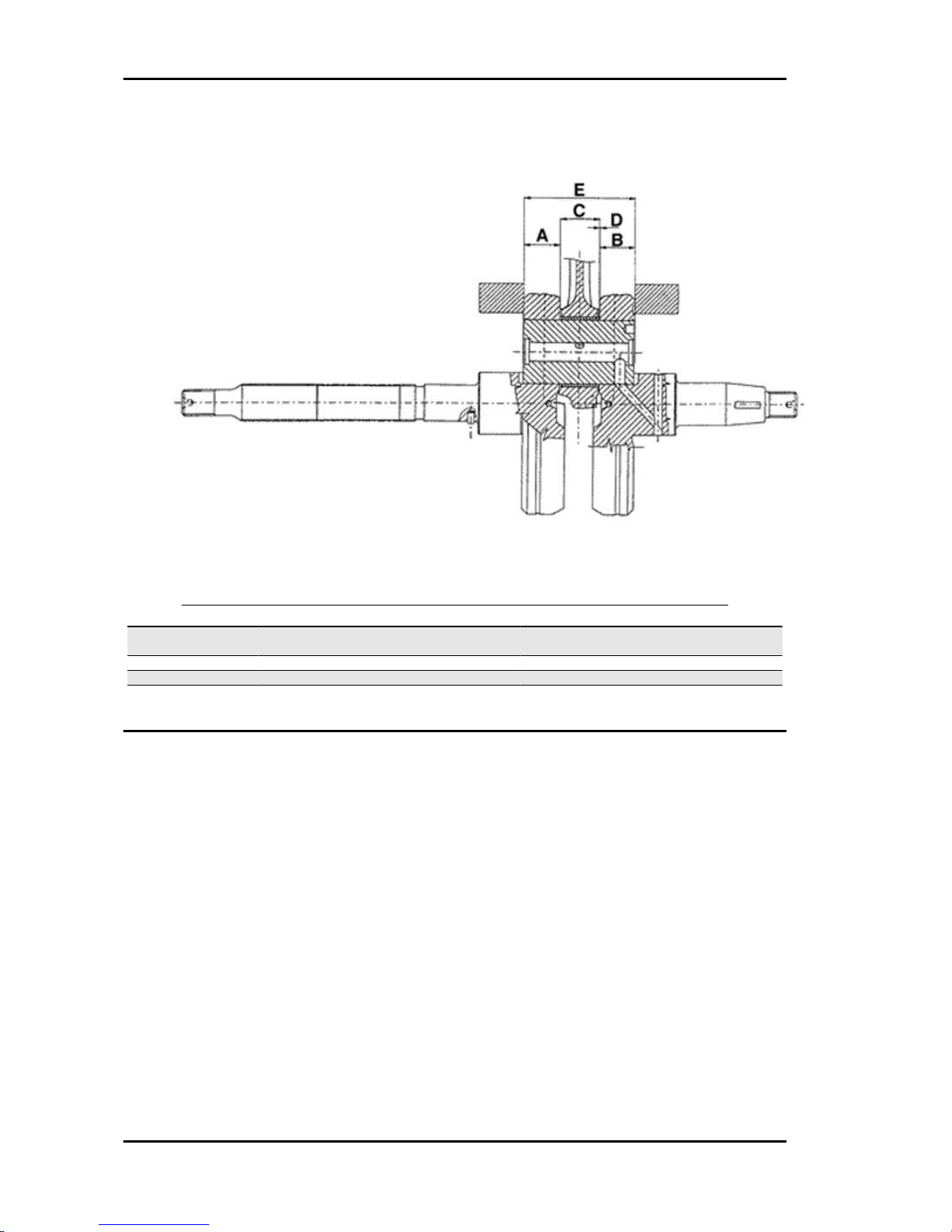
Crankcase - crankshaft - connecting rod
AXIAL CLEARANCE BETWEEN CRANKSHAFT AND CONNECTING ROD
Name
Description Dimensions Initials Quantity
Half-shaft, transmission
side
14 +0 -0.005 A
Flywheel-side half-shaft 16 +0 -0.005 B
Connecting rod 14.8 +0.05 -0 C
Built-up camshaft 45.00 / Fits and clearan-
ces D = 0.15 ÷ 0.30
E
Characteristics MSS ZIP 100 4T
CHAR - 14
Page 15

Slot packing system
THE VALUE OF MEASUREMENT «A» TO BE TAKEN CAN REFER TO EITHER THE PROTRUSION
OR RE-ENTRY OF THE PISTON. VALUES «A» INDICATED BY «-» CORRESPOND TO RE-ENTRY
AND THOSE INDICATED BY «+» CORRESPOND TO PROTRUSION. THEREFORE, THE MORE
THE PISTON PROTRUDES BEYOND THE PLANE FORMED AT THE CYLINDER UPPER END, THE
THICKER THE GASKET TO BE USED AT THE CYLINDER BASE «B» SHOULD BE.
Characteristic
Shimming system to control the compression ratio
CR: 10.5 ÷ 11.5 : 1
CYLINDER HEIGHT
54.95 ± 0.05
HEAD GASKET THICKNESS (steel)
0.3 ± 0.05
BASE GASKET THICKNESS
Specification
Desc./Quantity
Size measured «A» -0.25 ÷ -0.05 0.4
Size measured «A» -0.05 ÷ -0.15 0.5
Products
TABLE OF RECOMMENDED PRODUCTS
Product
Description Specifications
AGIP ROTRA 80W-90 Rear hub oil SAE 80W/90 Oil that exceeds the re-
quirements of API GL3 specifications
AGIP CITY HI TEC 4T Oil to lubricate flexible transmissions
(brakes, throttle control and odometer)
Oil for 4-stroke engines
MSS ZIP 100 4T Characteristics
CHAR - 15
Page 16

Product Description Specifications
AGIP FILTER OIL Oil for air filter sponge Mineral oil with specific additives for in-
creased adhesiveness
AGIP GP 330 Grease (brake control levers, throttle
grip)
Calcium complex soap-based grease
with NLGI 2; ISO-L-XBCIB2
AGIP CITY HI TEC 4T Engine oil SAE 5W-40, API SL, ACEA A3, JASO MA
Synthetic oil
AGIP BRAKE 4 Brake fluid FMVSS DOT 4 Synthetic fluid
MONTBLANC MOLYBDENUM
GREASE
Grease for driven pulley shaft adjusting
ring and movable driven pulley housing
Grease with Molybdenum disulphide
AGIP GREASE PV2 Grease for steering bearings, bolt seat-
ings for swinging arms and faying surface
of driven pulley spring (only pulley side)
Soap-based lithium and zinc oxide
grease containing NLGI 2; ISO-L-
XBCIB2
Characteristics MSS ZIP 100 4T
CHAR - 16
Page 17

INDEX OF TOPICS
TOOLING TOOL
Page 18

RECOMMENDED TOOLS
Stores code Description
001330Y Tool for fitting steering seats
001467Y008 Pliers to extract 17 mm ø bearings
001467Y029 Bell for bearings, O.D. 38 mm
005095Y Engine support
008119Y009 Tube to assemble shafts and axles
020004Y Punch for removing fifth wheels from
headstock
020074Y Tool to align crankshaft
020150Y Air heater support
Tooling MSS ZIP 100 4T
TOOL - 18
Page 19

Stores code Description
020151Y Air heater
020392Y Fork to assemble piston and cylinder
020329Y Mity-Vac vacuum-operated pump
020330Y Stroboscopic light to check timing
020331Y Digital multimeter
MSS ZIP 100 4T Tooling
TOOL - 19
Page 20

Stores code Description
020332Y Digital rpm indicator
020333Y Single battery charger
020334Y Multiple battery charger
020335Y Magnetic support for dial gauge
494929Y Exhaust fumes analyser
Tooling MSS ZIP 100 4T
TOOL - 20
Page 21

BASIC TOOLS
Stores code Description
004499Y Bearing extractor. Fitted with: 1 Bell, 2
Sleeve, 3 Screw, 6 Ring, 27 Half rings, 34
Half rings
020055Y Wrench for steering tube ring nut
020162Y Flywheel extractor
020171Y Punch for driven pulley roller bearing
020265Y Bearing fitting base
020306Y Punch for assembling valve seal rings
MSS ZIP 100 4T Tooling
TOOL - 21
Page 22

Stores code Description
020340Y Flywheel and transmission oil seals fitting
punch
020358Y 37x40-mm Adaptor
020359Y 42 x 47 mm Adaptor - For main bearings
and wheel axle
020360Y 52x55-mm Adaptor
020362Y 12 mm guide
020363Y 20-mm guide
020364Y 25-mm guide
020376Y Adaptor handle
Tooling MSS ZIP 100 4T
TOOL - 22
Page 23

Stores code Description
020382Y Valve fitting/ removal tool
020382Y011 adapter for valve removal tool
020431Y Valve oil seal extractor
020432Y Tool to fit the start-up sector spring
020439Y 17-mm guide
020444Y Tool for fitting/ removing the driven pulley
clutch
MSS ZIP 100 4T Tooling
TOOL - 23
Page 24

Stores code Description
020449Y Piston position check support
020450Y Camshaft fitting/removal tool
020451Y Driving pulley lock wrench
020452Y Tube for removing and refitting the driven
pulley shaft
020456Y Ø 24 mm adaptor
020565Y Flywheel lock calliper spanner
020498Y Pin lock fitting tool
Tooling MSS ZIP 100 4T
TOOL - 24
Page 25

INDEX OF TOPICS
MAINTENANCE MAIN
Page 26

Maintenance chart
AFTER 1000 KM
Action
Engine oil - level check/ top-up
Hub oil level - replacement
Valve clearance - Check
Idle speed (*) - adjustment
Throttle lever - adjustment
Steering - adjustment
Brake control levers - greasing
Brake pads - check condition and wear
Brake fluid level - check
Safety locks - check
Electrical System and Battery - Check
Tyre pressure - check
Vehicle and brake test - road test
AT 6000; AT 18,000; AT 30,000; AT 42,000; AT 54,000; AT 66,000 KM
Action
Engine oil - change
Hub oil level - check
Oil filter - Replacement
Variable speed rollers - check or replacement
Driving belt - Check
Brake pads - check condition and wear
Brake fluid level - check
Electrical System and Battery - Check
Tyre condition and wear - Check
Tyre pressure - check
Vehicle and brake test - road test
AT 12000; AT 36,000; AT 60,000 KM
Action
Engine oil - change
Hub oil level - check
Spark plug - replacement
Oil filter - Replacement
Idle speed (*) - adjustment
Throttle lever - adjustment
Variable speed rollers - check or replacement
Driving Belt - replacement
Odometer gear - greasing
Steering - adjustment
Brake control levers - greasing
Brake pads - check condition and wear
Brake fluid level - check
Transmission elements - lubrication
Safety locks - check
Suspensions - Check
Electrical System and Battery - Check
Headlight - adjustment check
Tyre condition and wear - Check
Tyre pressure - check
Vehicle and brake test - road test
AT 24000 AND AT 48000 KM
Action
Engine oil - change
Hub oil level - replacement
Spark plug - replacement
Oil filter - Replacement
Maintenance MSS ZIP 100 4T
MAIN - 26
Page 27

Action
Valve clearance - Check
Idle speed (*) - adjustment
Throttle lever - adjustment
Variable speed rollers - check or replacement
Driving Belt - replacement
Cylinder ventilation system - check
Odometer gear - greasing
Steering - adjustment
Brake control levers - greasing
Brake pads - check condition and wear
Brake fluid level - check
Transmission elements - lubrication
Safety locks - check
Suspensions - Check
Electrical System and Battery - Check
Headlight - adjustment check
Tyre condition and wear - Check
Tyre pressure - check
Vehicle and brake test - road test
AFTER 72000 KM
Action
Engine oil - change
Hub oil level - replacement
Spark plug - replacement
Oil filter - Replacement
Valve clearance - Check
Idle speed (*) - adjustment
Throttle lever - adjustment
Variable speed rollers - check or replacement
Driving Belt - replacement
Cylinder ventilation system - check
Odometer gear - greasing
Steering - adjustment
Brake control levers - greasing
Brake pads - check condition and wear
Brake fluid hoses - replacement
Brake fluid level - check
Transmission elements - lubrication
Safety locks - check
Suspensions - Check
Electrical System and Battery - Check
Headlight - adjustment check
Tyre condition and wear - Check
Tyre pressure - check
Vehicle and brake test - road test
EVERY 3000 KM
Action
Air filter - cleaning
Engine oil - Check level /Top-up
EVERY 24 MONTHS
Action
Brake fluid - change
MSS ZIP 100 4T Maintenance
MAIN - 27
Page 28
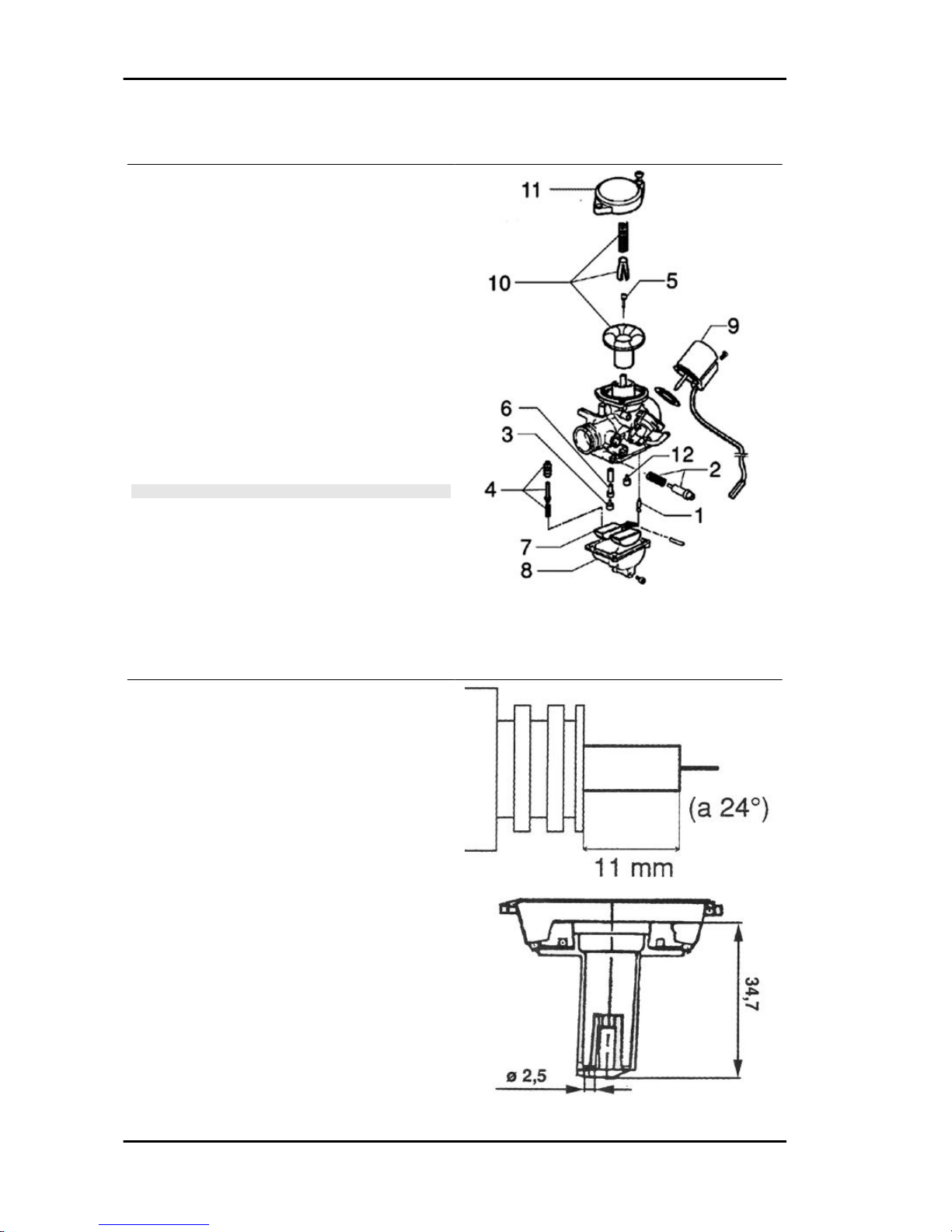
Carburettor
- Disassemble the carburettor in its parts, wash all
of them with solvent, dry all body grooves with
compressed air to ensure adequate cleaning.
- Check carefully that the parts are in good condition.
-The throttle valve should move freely in the
chamber. Replace valve in case of wear due to
excessive clearance.
- If there are wear marks in the chamber causing
inadequate tightness or a free valve slide (even if
it is new), replace the carburettor.
- It is advisable to replace the gaskets at every refit.
WARNING
PETROL IS HIGHLY EXPLOSIVE ALWAYS REPLACE THE
GASKETS TO AVOID PETROL LEAKS
1. Needle valve - 2. Idle speed adjustment screw - 3. Max jet - 4. Accelerating pump - 5. Tapered pin -
6. Jet holder - 7. Float - 8. Chamber - 9. Starter device - 10. Vacuum valve - 11. Cover - 12. Minimum
jet.
Specifications
Brand and Code: KEIHIN CVK 20
Adjustment code: AD8A
Type: vacuum
Diffuser diameter Ø 20.5 mm
Max. jet: 75
Min. jet: 35
Starter nozzle: 45
Starter nozzle code: 6ZC
Diffuser: Ø 2.1 mm
Tapered pin Type: 4 REEG
Notches from the top: the rod has no notches
Gasoline inlet hole: Ø 1.6 mm
Starter piston protrusion: 11 mm at 24ºC
Maintenance MSS ZIP 100 4T
MAIN - 28
Page 29

Checking the spark advance
The vehicle is fitted with a variable advance electronic device. There are two timing references on the
flywheel cover in order to ensure a better precision when detecting the reference on the fan. Use a
Tecnotest 130/P stroboscopic gun or a similar device to check. Start the engine and rev it to 1800 rpm
(engine idle speed), operate the phase shifter and align the reference on the flywheel fan in between
the two references done on the cover; at the same time read the advance value shown in the stroboscopic gun display; the value must be 10°. Repeat the operation with the engine at 5000 ÷ 6000 rpm;
the advance read must be 17°.
CAUTION
SHOULD THE FLASH INDICATIONS BE UNSTABLE AND THE RPM INDICATION DOES NOT
CORRESPOND WITH THE TRUE ENGINE SPEED VARIATION (FOR EXAMPLE, VALUES SHOWN
ARE HALVED), INSTALL A 10 ÷ 15 KΩ RESISTIVE CABLE CONNECTED IN SERIES TO AN HV
CABLE. IF THE IRREGULAR READING CONTINUES AFTER THIS OPERATION, CHECK THE
COMPONENTS OF THE IGNITION SYSTEM.
N.B.
WHEN THE INDUCTION CLAMP READS THE SIGNAL CORRECTLY, A READING CAN BE CARRIED OUT AT OVER 6000 RPM.
REVOLUTION LIMITER
Specification
Desc./Quantity
1 spark on 7 10300 Rpm
1 spark on 3 10400 Rpm
all sparks are suppressed 10500 Rpm
MSS ZIP 100 4T Maintenance
MAIN - 29
Page 30

Spark plug
- Disconnect and remove the spark plug pipe.
- Remove the spark plug; if necessary, use the
spanner supplied with the vehicle.
- Examine it carefully and replace it if the insulator
is chipped or cracked.
- Measure the electrode gap with a thickness
gauge and, if necessary, adjust the gap by carefully bending the outer electrode.
- Make sure the sealing washer is in good condition.
- Assemble the spark plug, screw it manually and
lock it to the prescribed torque with a spark plug
spanner.
Characteristic
Electrode gap
0.7 ÷ 0.8 mm
Recommended spark plug:
Champion RG 4 HC
CHAMPION RG 4 PHP
NGK CR9EB
Locking torques (N*m)
Spark plug 10 ÷ 15 Nm
Hub oil
Maintenance MSS ZIP 100 4T
MAIN - 30
Page 31

Check
- Park the scooter on level ground and rest it on
the centre stand.
- Unscrew the dipstick «A», dry it with a clean rag
and then reinsert it, screwing it tightly into
place.
- Take out the dipstick checking oil level is between
the second and third notch from the bottom (MAX
and MIN shown in figure).
- If the level is under the MIN notch, refill the hub
with the right amount of oil.
- Screw up the oil dipstick again and make sure it
is locked properly into place.
Recommended products
AGIP ROTRA 80W-90 Rear hub oil
SAE 80W/90 Oil that exceeds the requirements of
API GL3 specifications
Replacement
- Remove the oil filling cap/dipstick «A»
- Unscrew the oil drainage cap «B» shown in the
figure and drain out all the oil.
- Screw the drainage cap back and fill up the hub
with the required oil (about 80 cc)
MSS ZIP 100 4T Maintenance
MAIN - 31
Page 32

Air filter
Remove the air cleaner cap after undoing the 6
fixing screws, then extract the filter.
Cleaning:
- Wash with water and soap.
- Dry with a clean cloth without wringing.
- Soak with a mixture of 50% petrol and 50% SELENIA AIR FILTER OIL.
-Drip dry the filter and then squeeze it between the
hands without wringing.
N.B.
NEVER RUN THE ENGINE WITHOUT THE AIR FILTER,
THIS WOULD RESULT IN AN EXCESSIVE WEAR OF THE
PISTON AND CYLINDER.
Engine oil
Engine oil is used in 4T engines to lubricate the distribution elements, the bench bearings and the
thermal group. An insufficient quantity of oil can cause serious damage to the engine. In all 4T
engines, a loss of efficiency in oil performance and a certain level of consumption should be considered
normal. Consumption is specially affected by use conditions (e.g.: oil consumption increases when
driving at "full throttle". The replacement frequencies provided for by the maintenance programme are
defined, depending on the total contents of oil in the engine and average consumption measured following standardised methods. In order to avoid problems, it is advisable to control oil level every
time the vehicle is used.
Replacement
Replace oil and clean the mesh filter every 6,000
km. The engine must be drained by running off the
oil from drainage cap «B» with hot engine. To facilitate oil drainage, loosen the cap «C» and take
out the mesh filter. After cleaning and refitting the
mesh filter, tighten cap «C», refill with about 650
cc oil through cap «A». Then start up the scooter,
leave it running for a few minutes and switch it off:
5 minutes later check oil level and, if necessary,
add oil without exceeding the MAX level. Only use
new oil of the recommend type for oil top-ups and
change.
Maintenance MSS ZIP 100 4T
MAIN - 32
Page 33

CAUTION
USING THE ENGINE WITH INSUFFICIENT LUBRICATION
OR WITH THE WRONG LUBRICANTS MAY INCREASE
WEAR AND TEAR ON THE MOVING PARTS AND MAY RESULT IN SERIOUS DAMAGE.
WARNING
USED OIL CONTAINS ENVIRONMENTALLY HARMFUL
SUBSTANCES
Recommended products
AGIP CITY HI TEC 4T Engine oil
SAE 5W-40, API SL, ACEA A3, JASO MA Synthetic oil
Check
Every time the scooter is used, a visual check
should be made on the engine oil level when the
engine is cold. The oil level should be somewhere
between the MAX and MIN oil marks; during the
oil check, the vehicle must be resting on its centre
stand on an even, horizontal surface. The MAX
level mark indicates a quantity of around 850 cc of
oil in the engine. If the check is carried out after the
vehicle has been used, and therefore with a hot
engine, the level line will be lower; in order to carry
out a correct check it is necessary to wait at least
10 minutes after the engine has been stopped, so
as to get the correct level.
Oil top-up
Always check oil level before a top-up and add oil
without exceeding the MAX level. After every
3000 km check level and, if necessary, refill with
engine oil.
MSS ZIP 100 4T Maintenance
MAIN - 33
Page 34

Engine oil filter
- Change oil when the engine is hot.
- Place a container under the oil sump and remove
the oil drainage cap.
- After draining the oil, clean the mesh filter with a
specific solvent and then blow it with compressed
air.
- The filter can be reached after removing cap
"A" (see figure).
- After this operation, refit the filter and screw the
oil cap at the prescribed torque using a new ORing
- Refill the engine with oil through the oil filling hole
located in the oil sump.
- Engine oil capacity: ~ 850 cc.
- Lock the cap manually.
N.B.
MAKE THE ENGINE TURN FOR A COUPLE OF MINUTES
AND THEN CONTROL OIL LEVEL WHEN THE ENGINE IS
COLD. THE LEVEL SHOULD ALWAYS BE BELOW THE
MAX. NOTCH.
N.B.
IF IT IS THE 1ST TIME IT IS FILLED OR CHECKED, ADD 850
CC OF ENGINE OIL. IN ANY OTHER CIRCUMSTANCE OR
FOR TOP-UPS, ADD 650 CC.
Recommended products
AGIP CITY HI TEC 4T Engine oil
SAE 5W-40 Synthetic oil that exceed the requirements of API SL, ACEA A3, JASO MA specifications
Locking torques (N*m)
Engine oil pre-filter cover 25 ÷ 28 Nm
Maintenance MSS ZIP 100 4T
MAIN - 34
Page 35

Checking the ignition timing
- Turn the flywheel clockwise until its 2nd notch
coincides with the Pick-up reference mark as
shown in the figure.
Make sure that the reference point on the camshaft
command crown is aligned with the reference point
on the head as shown in the second figure.
If the reference is opposite the indicator on the
head, turn the crankshaft once more as the piston
must be at the TDC of the bursting phase.
N.B.
TIME THE TIMING SYSTEM UNIT AS DESCRIBED IN CHAP-
TER 6 IF IT IS NOT IN PHASE
Checking the valve clearance
- Remove the spark plug access cover, undo the
4 fixing screws indicated in the figure and remove
the tappet cover.
- To check valve clearance, centre the reference
marks of the timing system point as described
above.
- Use an adequate thickness gauge to check that
the clearance between the valve and the register
corresponds with the indicated values.
Should the valve clearance values, intake and
drainage respectively, be different from the ones
indicated below, adjust them by loosening the lock
nut and operate on the register with a screwdriver
as shown in the figure.
Characteristic
Inlet (with cold engine)
0.10 mm
Outlet (with cold engine)
MSS ZIP 100 4T Maintenance
MAIN - 35
Page 36

0.15 mm
Headlight adjustment
Proceed as follows:
1. Place the vehicle, in running order and with the
tyres inflated to the prescribed pressure, on a flat
surface 10-m away from a white screen situated in
a shaded area, making sure that the longitudinal
axis of the scooter is perpendicular to the screen;
2. Turn on the headlight and check that the borderline of the projected light beam on the screen
is not higher than 9/10 or lower than 7/10 of the
distance from the ground to the centre of vehicle
headlamp;
3. If otherwise, adjust the right headlight with screw
«A».
N.B.
THE ABOVE PROCEDURE COMPLIES WITH THE EURO-
PEAN STANDARDS REGARDING MAXIMUM AND MINIMUM HEIGHT OF LIGHT BEAMS. REFER TO THE STATUTORY REGULATIONS IN FORCE IN EVERY COUNTRY
WHERE THE VEHICLE IS USED.
CO check
- CO checking may be necessary when an engine operation failure is detected or during engine idle
speed adjustment operations.
- This test must be carried out after washing all carburettor parts carefully, the air filter must be clean
and the ignition spark plug in good conditions.
1) warm up the vehicle travelling on the streets at about 50 km/h for ~5 minutes; time enough for the
automatic starter to exclude the circuit.
2) Shut off the vehicle only for the time required to carry out steps 3) and 4).
3) Connect a - 50 cm extension pipe to the exhaust fumes intake in the muffler.
4) Make sure the muffler and the pipe are adequately connected and tight. Insert the exhaust fumes
analyser probe into the pipe.
5) Connect the tester thermometer to the sump, using a cover with oil expressly prepared for probes.
6) Start the engine and before adjusting the idle speed, make sure that the oil temperature is between
70÷80 °C.
7) Wait until the idle speed stabilises for one minute.
8) Without operating the accelerator again and using the flow screw rev the engine at 1500±150
rpm.
Maintenance MSS ZIP 100 4T
MAIN - 36
Page 37

9) Adjust the flow screw so that the "CO" value is equal to 3.2 % :t 0.5 %.
10) Slowly operate the throttle accelerating the engine until it reaches 4000 rpm and then set throttle
back to close position; check that the idle speed remains at the above set value; if not, repeat the
procedure starting from step (3).
Specific tooling
020332Y Digital rpm indicator
494929Y Exhaust fumes analyser
020331Y Digital multimeter
MSS ZIP 100 4T Maintenance
MAIN - 37
Page 38

INDEX OF TOPICS
TROUBLESHOOTING TROUBL
Page 39

EXCESSIVE FUEL CONSUMPTION
Possible Cause Operation
Air filter obstructed or dirty. Dismantle the sponge, wash with water and shampoo, then
soak it in a mixture of 50% petrol and 50% Selenia Air Filter Oil,
then allow to drip dry. Wring out water manually without
squeezing and reassemble
The starter remains on Check that the starter runs correctly and it is properly powered
Loose nozzles Check the maximum and minimum nozzles are adequately
fixed in their fittings
Incorrect float level Restore the correct level in the chamber (the float must be par-
allel to the upper cover contact plane, that is the throttle valve
membrane cover)
FAULTY CLUTCH
Possible Cause Operation
Tear or irregular functioning Check that there is no grease on the masses. Check that the
clutch masses' contact surface with the clutch bell is mainly in
the middle with equivalent specifications on the three masses.
Check that the clutch bell is not scored or worn abnormally
This section makes it possible to find the solutions to use in troubleshooting.
For each breakdown, a list of the possible causes and respective interventions is given.
Engine
Poor performance
LOW COMPRESSION
Possible Cause
Operation
Wrong valve adjustment Adjust the valve clearance properly
incorrect valve sealing Remove the head and the valves, grind the seats, descale the
valve heads and, if necessary, replace any faulty part.
Valve seat distorted Replace the head assembly
Worn or broken cylinder or piston rings Replace the piston cylinder assembly or the piston rings
POOR PERFORMANCE
Possible Cause
Operation
The carburettor is dirty; vacuum operated cock failure Dismantle, wash with solvent and dry with compressed air or
replace
Excess of scales in the combustion chamber Descale the cylinder, the piston, the head and the valves
Incorrect timing or worn timing system elements Time the system again or replace the worn parts
Muffler obstructed Replace
Automatic starter failure Check: mechanical movement, electric connection and fuel
supply, replace if required.
Oil level exceeds maximum Check for causes and fill to reach the correct level
Lack of compression: parts, cylinder and valves worn Replace the worn parts
Driving belt worn Replace
Inefficient automatic transmission Check the rollers and the pulley movement, replace the dam-
aged parts and lubricate the driven pulley moveable guide with
Montblanc Molybdenum Grease
Clutch slipping Check the clutch system and/or the bell and replace if neces-
sary
Overheated valves Remove the head and the valves, grind or replace the valves
Wrong valve adjustment Adjust the valve clearance properly
Valve seat distorted Replace the head unit
MSS ZIP 100 4T Troubleshooting
TROUBL - 39
Page 40

Possible Cause Operation
Air filter blocked or dirty. Dismantle the sponge, wash with water and shampoo, then
soak it in a mixture of 50% petrol and 50% of specific oil (Selenia Air Filter Oil), then hand dry without squeezing, allow to
drip dry and then reassemble.
Defective floating valve Check the proper sliding of the float and the functioning of the
valve
Rear wheel spins at idle
REAR WHEEL
Possible Cause Operation
Idling rpm too high Check the idling speed and, if necessary, adjust the C.O.
Clutch fault Check the spring/friction mass and the clutch bell
Air filter housing not sealed Correctly refit the filter housing and replace it if it is damaged
Purifier-carburettor fitting damaged Replace
Starting difficulties
DIFFICULTY STARTING UP
Possible Cause Operation
Defective spark plug or with incorrect electrode gap Check and if necessary replace the spark plug and the elec-
trode gap
Battery flat Check the state of the battery. If it shows signs of sulphation
replace it and bring the new battery into service charging it for
eight hours at a current of 1/10 of the capacity of the battery
itself
- Engine flooded. Start the vehicle keeping the throttle fully open alternately making the engine run for approx. five seconds and stopping for
other five seconds. If however it does not start, remove the
spark plug, the engine over with the throttle open being careful
to keep the cap in contact with the spark plug and the spark
plug grounded but away from its hole. Refit a dry spark plug
and start the vehicle.
Vacuum operated cock failure Check that fuel is adequately supplied through the pipe by ap-
plying a vacuum on the suction pipe
Failing automatic starter on the carburettor Check the electrical wiring and mechanical movement, replace
if necessary.
Wrong ignition advance Check flywheel keying on the crankshaft, replace control unit if
necessary
Incorrect valve sealing or valve adjustment Remove the head and the valves, grind the seats, descale the
valve heads and, if necessary, replace any faulty part. check
and restore the correct valve clearance.
Start-up rpm too low or starter motor failure Check starter motor
Altered fuel characteristics Drain off the fuel no longer up to standard; then, refill
Carburettor nozzles clogged or dirty Dismantle, wash with solvent and dry with compressed air
Excessive oil consumption/Exhaust smoke
RICH OR GREASY MIX
Possible Cause
Operation
Air calibrated holes in carburettor blocked Dismantle, wash with solvent and dry with compressed air
Defective floating valve Check the proper sliding of the float and the functioning of the
valve
Level in chamber too high Restore the correct level in the chamber (the float must be par-
allel to the upper cover contact plane, that is the throttle valve
membrane cover)
The starter remains on Check that the automatic starter works and moves correctly
and it is properly powered.
Troubleshooting MSS ZIP 100 4T
TROUBL - 40
Page 41

Possible Cause Operation
Air filter dirty Dismantle the sponge, wash with water and shampoo, then
soak it in a mixture of 50% petrol and 50% Selenia Air Filter Oil,
then allow to drip dry. Wring out water manually without
squeezing and reassemble.
EXCESSIVE OIL CONSUMPTION/SMOKEY EXHAUST
Possible Cause Operation
Worn or broken cylinder or piston rings Replace the piston cylinder assembly or the piston rings
Oil leaks from the couplings or from the gaskets Check and replace the gaskets or restore the coupling seal
Worn valve oil guard Replace the valve oil guard
Worn valve guides Check and replace the head unit if required
Insufficient lubrication pressure
POOR OR LEAN MIX
Possible Cause Operation
Carburettor nozzles clogged Dismantle, wash with solvent and dry with compressed air
Defective floating valve Check the proper sliding of the float and the functioning of the
valve
Level in chamber too low Restore the correct level in the chamber (the float must be par-
allel to the upper cover contact plane, that is the throttle valve
membrane cover)
Tank breather hole obstructed Restore the proper reservoir aeration
Fuel filter on vacuum operated cock blocked Clean the cock filter
Fuel supply pipes choked or clogged Restore the adequate fuel supply
Intake joint cracked or with a bad seal Replace intake joint and check for correct sealing on the head
Air filter housing not sealed Correctly refit the filter housing and replace it if it is damaged
Purifier-carburettor fitting damaged Replace
POOR LUBRICATION PRESSURE
Possible Cause
Operation
By-Pass remains open Check the By-Pass and replace if required. Carefully clean the
By-Pass area.
Oil pump with excessive clearance Perform the dimensional checks on the oil pump components
Oil filter too dirty Replace the cartridge filter
Oil level too low Restore the level using the recommended oil type (Selenia HI
Scooter 4 Tech)
Engine tends to cut-off at full throttle
THE MOTOR TENDS TO STOP AT MAXIMUM THROTTLE
Possible Cause
Operation
Maximum jet clogged Remove the carburettor, wash with solvent and dry with com-
pressed air
Incorrect ignition advance Use a stroboscopic light to check ignition advance and the fly-
wheel correct keying
Water or condensation in the carburettor chamber Remove the chamber, wash with solvent and dry with com-
pressed air or empty the tank through the appropriate bleed
screw
Air filter obstructed or dirty. Dismantle the sponge, wash with water and shampoo, then
soak it in a mixture of 50% petrol and 50% Selenia Air Filter Oil,
then allow to drip dry. Wring out water manually without
squeezing and reassemble
Incorrect float level Check and restore the correct fuel level in the chamber
MSS ZIP 100 4T Troubleshooting
TROUBL - 41
Page 42

Engine tends to cut-off at idle
THE ENGINE TENDS TO STOP AT IDLE SPEED
Possible Cause Operation
Wrong idling adjustment Correctly adjust the engine idling and check the level of the
C.O.
Spark plug defective or faulty Replace the spark plug with one with the specified degree and
check the plug gap
The starter remains activated Check that the automatic starter works and moves correctly
and it is properly powered.
Minimum jet dirty Remove the carburettor, wash with solvent and dry with com-
pressed air
Electronic ignition circuit failure Use a stroboscopic light and an rpm indicator to check for cor-
rect ignition advance and make sure the flywheel is correctly
keyed
Pressure too low at the end of compression Check the thermal group seals and replace worn components;
check and restore the correct valve clearance.
Incorrect timing Time the system and check the timing system components
Excessive exhaust noise
EXCESSIVE EXHAUST NOISE
Possible Cause
Operation
Depression intake pipe of the secondary air device disconnec-
ted or dented
Replace the pipe
Reed valve of the secondary air device does not close correctly
and wears out the rubber coupling between the device and the
head pipe
Replace the device and the coupling
High fuel consumption
HIGH FUEL CONSUMPTION
Possible Cause
Operation
Float level Restore the level in the tank by bending on the float the thrust-
ing reed of the petrol inlet rod so as to have the float parallel to
the tank level with the carburettor inverted.
Loose nozzles Check the maximum and minimum nozzles are adequately
fixed in their fittings
Starter inefficient Check: electric wiring, circuit continuity, mechanical sliding and
power supply
Air filter blocked or dirty. Dismantle the sponge, wash with water and shampoo, then
soak it in a mixture of 50% petrol and 50% of specific oil (Selenia Air Filter Oil), then hand dry without squeezing, allow to
drip dry and then reassemble.
SAS malfunctions
ANOMALIES IN THE SECONDARY AIR DEVICE
Possible Cause
Operation
Depression intake pipe of the secondary air device disconnec-
ted or dented
Replace the pipe
Reed valve of the secondary air device does not close correctly
and wears out the rubber coupling between the device and the
head pipe
Replace the device and the coupling
Troubleshooting MSS ZIP 100 4T
TROUBL - 42
Page 43

Transmission and brakes
REAR BRAKE LEVER FAIL TO RETURN
Possible Cause Operation
Return spring broken Replace spring.
Shoe control bolt not lubricated Lubricate with Z2 grease.
Clutch grabbing or performing inadequately
IRREGULAR CLUTCH PERFORMANCE OR SLIPPAGE
Possible Cause Operation
Faulty clutch Check that there is no grease on the masses. Check that the
clutch mass faying surface with the bell is mainly in the centre
with equivalent characteristics on the three masses. Check that
the clutch casing is not scored or worn in an anomalous way
Insufficient braking
INEFFICIENT OR NOISY BRAKING
Possible Cause
Operation
Brake pads or shoes worn Replace the brake pads or shoes and check for brake disk or
drum wear conditions. If the front calliper is removed to facilitate
replacement, remember to replace the copper gaskets located
on the tube joint when refitting; failure to do so may result in
inadequate tightness; it is necessary to bleed the brakes after
this operation.
Air bubbles inside the hydraulic braking system Carefully bleed the hydraulic braking system, (there must be
no flexible movement of the brake lever).
Brake disc or drum deformed Use a dial gauge to check the levelness of the disk with the
wheel correctly fitted and the concentricity of the rear drum;
check the brake disc screws are locked
Fluid leakage in hydraulic braking system Elastic fittings, piston seals or brake pump breakdown, replace
Excessive backlash in the rear brake control cable Adjust backlash with the appropriate adjuster on the shoe con-
trol lever
The brake fluid has lost its properties Replace the front brake fluid and top up to the correct level in
the pump
INSUFFICIENT BRAKING
Possible Cause
Operation
Inefficient braking system Check the pad wear (1.5 min). Check that the brake discs are
not worn, scored or warped. Check the correct level of fluid in
the pumps and change brake fluid if necessary. Check there is
no air in the circuits; if necessary, bleed the air. Check that the
front brake calliper moves in axis with the disc.
Fluid leakage in hydraulic braking system Failing elastic fittings, plunger or brake pump seals, replace
Brakes overheating
BRAKES OVERHEATING
Possible Cause
Operation
Defective plunger sliding Check calliper and replace any damaged part.
Brake disc or drum deformed Use a dial gauge to check the levelness of the disk with the
wheel correctly fitted and the concentricity of the rear drum;
check the brake disc screws are locked
MSS ZIP 100 4T Troubleshooting
TROUBL - 43
Page 44

Electrical system
Battery
BATTERY
Possible Cause Operation
The battery is the electrical device in the system that requires
the most frequent inspections and thorough maintenance.
The battery is the electrical device in the system that requires
the most frequent inspections and thorough maintenance. If the
vehicle is not used for some time (1 month or more) the battery
needs to be recharged periodically. The battery runs down
completely in the course of 5 ÷ 6 months. If the battery is fitted
on a motorcycle, be careful not to invert the connections, keeping in mind that the black earth wire is connected to the negative
terminal while the red wire is connected to the terminal marked
+.
Turn signal lights malfunction
ELECTRICAL SYSTEM MALFUNCTION
Possible Cause
Operation
Turn indicators do not turn on Check turn indicators device and/or wiring as described in the
«Electrical system» chapter.
TURN INDICATOR NOT WORKING
Possible Cause
Operation
Electronic ignition device failure With the key switch set to "ON" jump the contacts 1 (Blue -
Black) and 3 (White) on the voltage regulator connector. If by
operating the turn indicator control the lights are not steadily
on, replace the control unit; otherwise, check the cable harness
and the switch.
Steering and suspensions
Rear wheel
REAR WHEEL ROTATES WITH ENGINE AT IDLE
Possible Cause
Operation
Idling rpms too high Adjust the engine idle speed and the CO%, if necessary.
Clutch fault Check the springs / clutch masses
Controls
STEERING AND SUSPENSIONS CONTROLS
Possible Cause
Operation
Steering hardening Check the tightening of the top and bottom ring nuts. If irregu-
larities continue in turning the steering even after making the
above adjustments, check the seats in which the ball bearings
rotate: replace them if they are recessed or if the balls are flat-
tened.
Troubleshooting MSS ZIP 100 4T
TROUBL - 44
Page 45

Possible Cause Operation
Excessive steering clearance Check the tightening of the top ring nut. If irregularities continue
in turning the steering even after making the above adjust-
ments, check the seats in which the ball bearings rotate: re-
place if they are recessed.
Noisy suspension If the front suspension is noisy, check: that the front shock ab-
sorber works properly and the ball bearings are good condition.
In conclusion, check the tightening torque of the wheel hub, the
brake calliper, the shock absorber disk in the attachment to the
hub and the steering tube.
Check that the swinging arm connecting the engine to the
chassis and the rear shock absorber work properly
Oil leakage from suspension Replace the shock absorber
MSS ZIP 100 4T Troubleshooting
TROUBL - 45
Page 46

INDEX OF TOPICS
ELECTRICAL SYSTEM ELE SYS
Page 47

KEY
1. Electronic ignition device
2. Spark plug
3. Magneto flywheel
4. Voltage regulator
5. Main fuse
6. Key switch
7. Battery
8. Starter motor
9. Starter remote control
10. Starter button
11. Rear brake STOP button
12. Front brake STOP button
13. Horn button
14. Horn
15. Left rear turn indicator bulbs
16. Tail lights/stop light bulbs
17. Turn indicator switch
18. Right rear turn indicator bulbs
19. Left side headlight assembly
MSS ZIP 100 4T Electrical system
ELE SYS - 47
Page 48

A. Left front turn indicator bulb
B. Front position light bulb
20. Headlight assembly with high-/low-beam bulb
21. Right side headlight assembly
A. Left front turn indicator bulb
B. Front position light bulb
22. Light switch
23. Instrument panel
A. Turn indicator warning light
B. High-beam warning light
C. Low fuel warning light
D. Instrument panel bulb
E. Instrument panel bulb
24. Fuel level warning light control
25. Automatic starter
26. Resistance
Ar = Orange, Az = Sky Blue, Bi = White, Bl = Blue, Gi = Yellow, Gr = Grey, Ma = Brown, Ne = Black,
Ro = Pink, Rs = Red, Ve = Green, Vi = Purple
Conceptual diagrams
Electrical system MSS ZIP 100 4T
ELE SYS - 48
Page 49

Ignition
KEY
1. Electronic ignition device
2. Spark plug
3. Magneto flywheel
6. Key switch
MSS ZIP 100 4T Electrical system
ELE SYS - 49
Page 50

Headlights and automatic starter section
KEY
3. Magneto flywheel
4. Voltage regulator
16. Tail lights/stop light bulbs
19. Left side headlight assembly
A. Left front turn indicator bulb
B. Front tail light bulb
20. Headlight assembly with high-/low-beam bulb
21. Right side headlight assembly
A. Left front turn indicator bulb
B. Front position light bulb
22. Light switch
23. Instrument panel
25. Automatic starter
26. Resistance
Electrical system MSS ZIP 100 4T
ELE SYS - 50
Page 51

Battery recharge and starting
KEY
3. Magneto flywheel
4. Voltage regulator
5. Main fuse
6. Key switch
7. Battery
8. Starter motor
9. Starter remote control
10. Starter button
11. STOP button on rear brake
12. Front brake STOP button
16. Tail lights/stop light bulbs
MSS ZIP 100 4T Electrical system
ELE SYS - 51
Page 52

Level indicators and enable signals section
KEY:
5. Main fuse
6. Key switch
7. Battery
23. Instrument panel
A. Flashing warning light
B. High-beam warning light
C. Low fuel warning light
D. Instrument panel bulb
E. Instrument panel bulb
24. Fuel level warning light control
Electrical system MSS ZIP 100 4T
ELE SYS - 52
Page 53

Turn signal lights
KEY:
3. Magneto flywheel
4. Voltage regulator
5. Main fuse
6. Key switch
7. Battery
13. Horn button
14. Horn
15. Left rear turn indicator bulbs
17. Turn indicator switch
18. Right rear turn indicator bulbs
19. Left side headlight assembly
A. Left front turn indicator bulb
B. Front tail light bulb
21. Right side headlight assembly
A. Left front turn indicator bulb
B. Front tail light bulb
23. Instrument panel
MSS ZIP 100 4T Electrical system
ELE SYS - 53
Page 54

A. Flashing warning light
B. High-beam warning light
C. Low fuel warning light
D. Instrument panel bulb
E. Instrument panel bulb
Checks and inspections
In case the cause of ignition failure or malfunction
cannot be easily identified at sight, first of all replace the control unit by another one in operating
conditions.
Remember that the engine must be off to disconnect and replace the control unit.
If after replacement the vehicle starts properly, the
control unit is failing and must be replaced.
If the failure persists, check the generator and the
stator components as follows:
After a sight control of the electrical connections,
use a specific tester to measure the stator winding
and the pick-up.
If checks on the loading coil, pick-up detect irregularities, replace the stator and the failing com-
ponents.
Disconnect the connector on the flywheel cover
and measure the resistance between either contact and the earthing.
Specific tooling
020331Y Digital multimeter
PICK-UP CHECK
Specification
Desc./Quantity
1 1) Brown cable and earth ~ 170 Ω
STATOR WINDING CHECK
Specification
Desc./Quantity
1 1) Black cable and earth ~ 1 Ω
Electrical system MSS ZIP 100 4T
ELE SYS - 54
Page 55

KEY:
Br= brown
Bl= black
A= Pick-up
B= Stator
Ignition circuit
All the control operations of the system that require
the disconnection of cables (checks of the connections and the devices making up the ignition
circuit) must be done with the engine off: if this is
not done, the controls might be irretrievably damaged.
Stator check
- Using a tester, check the resistance between the
brown-earth and black-earth terminal.
N.B.
VALUES ARE STATED AT AMBIENT TEMPERATURE. A
CHECK WITH THE STATOR AT OPERATING TEMPERATURE LEADS TO VALUES HIGHER THAN THOSE STATED.
Electric characteristic
Stator : Brown-earth
approx. 170 Ω (Pick-Up)
Stator : Black-earth
~ 1 Ω (Stator)
MSS ZIP 100 4T Electrical system
ELE SYS - 55
Page 56

Voltage regulator check
A malfunction in the voltage regulator might cause the following problems depending on the type of
fault:
Alternating current section
1) Bulbs burned out (regulator in short circuit).
2) Malfunctioning of the lighting system and the
electric starter (regulator interrupted).
Direct current section
3) Battery not recharging.
4) Turn indicators not working.
The regulator is earthed through the electrical system, so the regulator body does not earth the
circuits inside the regulator.
There must be insulation between each regulator
terminal and the regulator body (use the tester to
check electric resistance).
Measures
1) Bulbs burn out
Replace the regulator because it is certainly inefficient.
2) Lights and starter not working
Gain access to the voltage regulator, start the engine and keep it at idle speed; keep the vehicle
lighting system off.
Connect the tester positive end (select it to detect
alternating voltage) to terminal No 1 (grey cable)
and the negative end to terminal No 2 (black cable); check there is voltage (see figure).
If there is voltage, check the wiring connecting
lights switch and the regulator and make sure the
switch works properly.
If no voltage is detected, try connecting the negative end directly to earth; if voltage is detected with
this operation, check the earth wiring of the regulator; otherwise, replace the regulator because it
is damaged.
Electrical system MSS ZIP 100 4T
ELE SYS - 56
Page 57

As a last check, the voltage supplied by the stator
can be measured:
- Disconnect the regulator connector and place a
tester between the Grey-Blue cable (4) and the
earth in order to detect alternating voltages (see
figure).
- Voltage supplied at 2000 rpm must be about 25
÷ 35V.
If no values are detected with this test, replace the
regulator because it is obviously broken.
N.B.
TO MEASURE THE ABOVE VOLTAGE USE AN ANALOGUE
TESTER THAT CAN MEASURE ALTERNATING VOLTAGES AND KEEP THE ENGINE AT IDLE TO HAVE AN ALTERNATING VOLTAGE OF A FREQUENCY AS CLOSE AS
POSSIBLE TO 50HZ SO AS TO DETECT THE EFFICIENT
VOLTAGE VALUE SUPPLIED BY THE REGULATOR
(ABOUT 12V).
Recharge system voltage check
3) Battery fails to recharge
a failure in the direct current section of the voltage
regulator may cause the following problems depending on the type of fault:
a) Protection fuse blows due to overvoltage
(regulator in short circuit) and consequently
the battery fails to recharge.
b) Battery fails to recharge (regulator interrupted).
Measures
a) Protection fuse blows (regulator in short circuit).
Check that the wiring connecting the protection
fuse and the key switch is not damaged and causing a short circuit to the earth (thus excluding the
possibility that the regulator is damaged); if the
protection fuse blows only after the key switch is
set to "ON" and with the regulator connector disconnected, check that the upstream wiring and
devices of the key switch are not in short circuit to
the earth. Now measure the resistance between
contact 3 (White) and contact 2 (Black) of the volt-
MSS ZIP 100 4T Electrical system
ELE SYS - 57
Page 58

age regulator (with connector disconnected); the
measurement must be ~8 M/Ohm. If the value
measured is far from that indicated, replace the
regulator because it is in short circuit.
b) Battery fails to recharge (regulator interrupted).
To check if there is any failure in the voltage regulator recharge section, first connect 2 testers to
the battery (one to detect voltage and the other to
detect current) as indicated in the second figure
and follow the procedure below:
Start the engine (temporarily connect the red cable
to the battery positive terminal in order to avoid
damaging the device that measures current).
Check there is at least 13V (charged battery) and
a recharge current of 1.5 ÷ 2A with the vehicle
lights off.
As the engine rpm increases, so do the current and
the recharge voltage; with rpm over 4000 there
must be a recharge current of about 4.5A; when
the vehicle lights and the stop light are switched
on and the horn is powered, current values below
or equal to 5A and a voltage value of 14 ÷ 14.5V
( regulator threshold voltage) can be registered. If
values other than those above are detected, replace the regulator; contrariwise, check the cable
harness and the connections.
Starter motor
Test to be carried out to check the electrical starter motor
1) Check the battery charging conditions.
2) - Check the remote control and the system. The check can be carried out by replacing a 12V-35W
bulb of the starter.
- If the bulb turns on, replace the starter motor.
- If the bulb does not turn on, check the system and the remote control.
Starter motor
Specifications:
- Nominal voltage 12V.
Electrical system MSS ZIP 100 4T
ELE SYS - 58
Page 59

- Nominal power 0.25 kW.
- Leftward rotation seen from the pinion side.
- Connection to the engine by means of pinion and crown gear on the crankshaft, transmission side.
- Control with switch.
- Battery used for the test: 12V-7Ah.
Turn signals system check
4) Turn indicators not working
If the turn indicators do not work, do the following:
- Disconnect the regulator connection and insert
the tester end between the white cable (3) and the
black one (2).
- Turn the key switch to ON and check that the
battery is getting voltage. If no voltage is detected,
repeat the test now between the white cable and
the earth; if there is no voltage even after this operation, check the wiring and the contacts of the
key switch and the battery. If voltage in the battery
is detected (black cable), check the regulator earth
wiring.
- If the above tests have positive results, jump the
contacts 5 (blue/black) and 3 (white) on the connector, set the key switch to ON and turn the turn
indicator switch left and right to see when the lights
are steadily on (as they are powered directly from
the battery). If even after this operation the turn
indicators fail to turn on, check the wiring is not
damaged and switch works properly; If these last
two tests have a positive result, replace the regulator because it is certainly not functioning properly.
Specific tooling
020331Y Digital multimeter
MSS ZIP 100 4T Electrical system
ELE SYS - 59
Page 60

Fuses
The electrical system is protected by a 10 A fuse
«A» located to the left of the battery support. The
ignition system, the automatic starter, front headlight and the tail light are not fuse-protected. Before replacing a blown fuse, find and solve the
problem that caused it to blow. Do not substitute
the fuse with any alternative form of conductor
BATTERIES CONTAIN VERY ENVIRONMENTAL DANGEROUS SUBSTANCES. FOR BATTERY REPLACEMENT,
CONTACT AN AUTHORISED PIAGGIO-GILERA SERVICE
CENTRE, AS THEY ARE EQUIPPED FOR THE DISPOSAL
IN AN ENVIRONMENTALLY FRIENDLY AND LEGAL WAY.
Sealed battery
Using the sealed battery for the first time
If the vehicle is provided with an airtight battery, the only maintenance required is the check of its charge
and recharging, if needed.
These operations should be carried out before delivering the scooter, and on a six-month basis while
the vehicle is stored in open circuit.
Besides upon pre-delivery it is therefore necessary to check the battery charge and recharge it, if required, before storing the scooter and afterwards every six months.
Instructions for the renewal recharge after
open-circuit storage
1) Voltage check
Before installing the battery on the vehicle, check
the open circuit voltage with a normal tester.
- If the voltage exceeds 12.60 V, the battery may
be installed without any renewal recharge.
- If voltage is below 12.60 V, a renewal recharge
is required as explained in 2).
2) Constant voltage battery charge mode
-Constant voltage equal to 14.40 to 14.70V
-Initial charge voltage equal to 0.3 to 0.5 x nominal
capacity
-Duration of the charge: 10 to 12 h recommended
Minimum 6 h
Electrical system MSS ZIP 100 4T
ELE SYS - 60
Page 61

Maximum 24 h
3) Constant current battery charge mode
-Charge current equal to 1/10 of the nominal capacity of the battery
-Duration of the charge: 5 h
WARNING
-WHEN THE BATTERY IS REALLY FLAT (WELL BELOW
12.6V) IT MIGHT BE THAT 5 HOURS OF RECHARGING ARE
NOT ENOUGH TO ACHIEVE OPTIMAL PERFORMANCE.
IN THESE CONDITIONS IT IS HOWEVER ESSENTIAL NOT
TO EXCEED EIGHT HOURS OF CONTINUOUS RECHARGING SO AS NOT TO DAMAGE THE BATTERY ITSELF.
1 Hold the vertical tube
2 Look at the level
3 The float must be freed
Dry-charge battery
Battery maintenance
The battery is an electrical device which requires careful monitoring and diligent maintenance. The
maintenance rules are:
1) Check the level of the electrolyte
The electrolyte level must be checked frequently and must reach the upper level. Only use distilled
water, to restore this level. If it is necessary to add water too frequently, check the vehicle's electrical
system: the battery that is working in overloaded mode gets ruined quickly.
2)Load status check
After restoring the electrolyte level, check its density using an appropriate densitometer (see the figure).
When the battery is charged, you should detect a density of 30÷32 Bé corresponding to a specific weight
of 1.26÷1.28 at a temperature not lower than 15ºC. If the density has fallen below 20 Bé, the battery is
completely flat and therefore it is necessary to recharge it. After charging the battery, check each element electrolyte level and density. If the vehicle is not used for some time (1 month or more) the battery
needs to be recharged periodically. The battery runs down completely in the course of three months. If
it is necessary to refit the battery in the vehicle, be careful not to reverse the connections, remembering
that the ground wire (black) marked (-) must be connected to the -negative clamp while the other two
red wires marked (+) must be connected to the clamp marked with the +positive sign.
3) Recharging the battery
The normal bench charging must be carried out with the specific battery charger 020333Y (single) or
020334 (multiple), placing the battery charger selector on the type of battery to be recharged. The
connections to the power supply must be made by connecting to the corresponding poles (+ with+ and
-with -).
WARNING
BEFORE RECHARGING THE BATTERY, REMOVE THE CAPS OF EACH CELL.
MSS ZIP 100 4T Electrical system
ELE SYS - 61
Page 62

KEEP THE BATTERY AWAY FROM NAKED FLAMES OR SPARKS WHILE IT IS CHARGED.
FIRST DETACH THE NEGATIVE LEAD BEFORE REMOVING THE BATTERY FROM THE VEHICLE.
4) Cleaning the battery
You are advised to keep the battery clean,especially in the upper part, and to protect the terminals with
Vaseline.
CAUTION
NEVER USE FUSES WITH A CAPACITY HIGHER THAN THAT RECOMMENDED. USING A FUSE
OF UNSUITABLE RATING MAY SERIOUSLY DAMAGE THE VEHICLE OR EVEN CAUSE A FIRE.
CAUTION
ORDINARY AND DRINKING WATER CONTAINS MINERAL SALTS THAT ARE HARMFUL FOR
THE BATTERY. FOR THIS REASON, YOU MUST ONLY USE DISTILLED WATER.
CAUTION
TO ENSURE MAXIMUM PERFORMANCE, THE BATTERY MUST BE CHARGED BEFORE USE.
INADEQUATE CHARGING OF THE BATTERY WITH A LOW LEVEL OF ELECTROLYTE BEFORE
IT IS FIRST USED SHORTENS THE LIFE OF THE BATTERY.
Use of dry-cell batteries :
1) Having removed the short, closed tube and removed the caps, put into the elements sulphuric acid
of the type for specific weight 1.26 accumulators corresponding to 30 Bé at a temperature of no less
than 15°C, until the upper level is reached.
2)Leave to rest for at least 2 hours; then, restore the level with sulphuric acid.
3) Within the following 24 hours, recharge with the specific battery charger 020333Y (single) or 020334Y
(multiple) at a density of about 1/10 of the battery nominal capacity and until the acid density is about
1.27, corresponding to 31Bé, and these values are stabilised.
4) Once the charge is over, level the acid (by adding distilled water). Replace the caps and clean
carefully.
5)Once the above operations have been performed, install the battery in the vehicle ensuring the connections between the wiring and the battery terminals are correct.
WARNING
- ONCE THE BATTERY HAS BEEN INSTALLED IN THE VEHICLE IT IS NECESSARY TO REPLACE
THE SHORT TUBE (WITH CLOSED END) NEAR THE + POSITIVE TERMINAL WITH THE CORRESPONDING LONG TUBE (WITH OPEN END), THAT YOU FIND FITTED TO THE VEHICLE, TO
ENSURE THAT THE GASES THAT FORM CAN ESCAPE PROPERLY.
WARNING
THE BATTERY ELECTROLYTE IS POISONOUS AS IT MAY CAUSE SERIOUS BURNS. IT CONTAINS SULPHURIC ACID. AVOID CONTACT WITH THE EYES, THE SKIN AND CLOTHING. IF
COMING INTO CONTACT WITH EYES OR SKIN, WASH ABUNDANTLY WITH WATER FOR APPROX. 15 MIN. AND SEEK IMMEDIATE MEDICAL ATTENTION.
IN THE EVENT OF ACCIDENTAL INGESTION OF THE LIQUID, IMMEDIATELY DRINK LARGE
QUANTITIES OF WATER OR MILK, MAGNESIUM MILK, BATTERED EGG OR VEGETABLE OIL.
SEEK IMMEDIATE MEDICAL ATTENTION.
THE BATTERIES PRODUCE EXPLOSIVE GAS; KEEP CLEAR OF NAKED FLAMES, SPARKS OR
CIGARETTES; VENTILATE THE AREA WHEN RECHARGING INDOORS.
ALWAYS WEAR EYE PROTECTION WHEN WORKING IN THE PROXIMITY OF BATTERIES.
KEEP OUT OF REACH OF CHILDREN
Electrical system MSS ZIP 100 4T
ELE SYS - 62
Page 63

INDEX OF TOPICS
ENGINE FROM VEHICLE ENG VE
Page 64

Exhaust assy. Removal
- Remove the 2 fixing nuts from the manifold to the
head
- Undo the 2 screws fixing the muffler to the housing; then remove the whole muffler paying attention to the interference between its supporting
bracket and the cooling cover.
Removal of the engine from the vehicle
Removing the engine from the chassis
-Disconnect the battery.
-Remove the muffler assembly.
- Remove the rear wheel.
- Remove the rear brake mechanical transmission.
-Disconnect the electric terminals.
-Remove the throttle grip transmission.
- Disconnect the tubing (petrol-vacuum operated cock control).
- Disconnect the swinging arm on the engine side
- Disconnect the rear shock absorber lower clamping
WARNING
Be very careful when handling fuel.
CAUTION
When installing the battery, first attach the positive cable and then the negative cable.
WARNING
Wear safety goggles when using hitting tools.
Engine from vehicle MSS ZIP 100 4T
ENG VE - 64
Page 65

INDEX OF TOPICS
ENGINE ENG
Page 66

Automatic transmission
Transmission cover
- Remove the 12 fixing screws.
- Remove the oil filling cap and then slide out the
cover.
If this operation is carried out directly on the vehicle, it is necessary to remove the transmission
cooling coupling and the air filter housing retainers.
N.B.
USE A MALLET ON THE APPROPRIATE COUPLINGS TO
REMOVE THE COVER.
Kickstart
-To remove the start up pinion push the starter
lever to facilitate extracting the pinion.
-Remove the kick-start screw and lever.
-Remove the Seeger ring and the washer indicated in the figure.
-Pull out the toothed sector.
WARNING
THE SECTOR KEEPS THE SPRING SET, BE CAREFUL SO
AS NOT TO CAUSE ANY ACCIDENTS
Air duct
- To remove the intake throat on the transmission
cover, just remove the three fixing screws indicated in the figure.
Engine MSS ZIP 100 4T
ENG - 66
Page 67

Removing the driven pulley shaft bearing
- Slightly heat the crankshaft from the inside side
to avoid damaging the coated surface and use the
driven pulley shaft or a pin of the same diameter
to remove the bearing.
N.B.
IN CASE OF DIFFICULTY A STANDARD 8MM-INSIDE DI-
AMETER EXTRACTOR CAN BE USED.
Refitting the driven pulley shaft bearing
Refit the bearing with the aid of a bushing with the same diameter as the external plate of the bearing
after slightly heating the crankcase from the inside.
N.B.
WHEN REFITTING, ALWAYS REPLACE THE BEARING WITH A NEW ONE.
CAUTION
WHEN REMOVING/REFITTING THE BEARING, TAKE CARE NOT TO DAMAGE THE COVER
PAINTED SURFACE.
Removing the driven pulley
- Lock the clutch bell housing with the specific tool.
- Remove the nut, the clutch bell housing and the
whole of the driven pulley assembly.
N.B.
THE UNIT CAN ALSO BE REMOVED WITH THE DRIVING
PULLEY MOUNTED.
Specific tooling
020565Y Flywheel lock calliper spanner
MSS ZIP 100 4T Engine
ENG - 67
Page 68

Inspecting the clutch drum
- Check that the clutch bell is not worn or damaged.
- Measure the inner diameter of the clutch bell.
Characteristic
Clutch bell diameter/standard value
Ø 107+0.2 +0 mm
Clutch bell diameter/max. value allowed after
use
Ø 107.5 mm
Eccentricity measured /max.
0.20 mm
Removing the clutch
- Equip the tool with long pins screwed into position
«A» from the outside, insert the entire driven pulley
in the tool and have the central screw make contact.
CAUTION
THE TOOL WILL BE DEFORMED IF THE CENTRAL SCREW
IS TIGHTENED UP TOO FAR.
- Using a 34 mm socket wrench remove the clutch
locking nut.
- Loosen the central screw by undoing spring of
the driven pulley unit
- Separate the components.
Specific tooling
020444Y Tool for fitting/ removing the driven
pulley clutch
Engine MSS ZIP 100 4T
ENG - 68
Page 69

Inspecting the clutch
- Check the thickness of the clutch mass friction
material.
- The masses must not show traces of lubricants;
otherwise, check the driven pulley unit seals.
N.B.
UPON RUNNING-IN, THE MASSES MUST EXHIBIT A CEN-
TRAL FAYING SURFACE AND MUST NOT BE DIFFERENT
FROM ONE ANOTHER.
VARIOUS CONDITIONS CAN CAUSE THE CLUTCH TO
TEAR.
CAUTION
DO NOT OPEN THE MASSES USING TOOLS TO PREVENT
A VARIATION IN THE RETURN SPRING LOAD.
Characteristic
Check minimum thickness
1 mm
Pin retaining collar
- Remove the collar with the aid of 2 screwdrivers.
- Remove the three guide pins and the mobile half
pulley.
MSS ZIP 100 4T Engine
ENG - 69
Page 70

Removing the driven half-pulley bearing
- Remove the roller bearing with the special extractor inserted from the bottom of the fixed halfpulley.
CAUTION
POSITION THE HOLDING EDGE OF THE EXTRACTION PLI-
ERS BETWEEN THE END OF THE BEARING AND THE
BUILT IN SEALING RING.
Specific tooling
001467Y029 Bell for bearings, O.D. 38 mm
- Remove the ball bearing retention snap ring.
- Expel the ball bearing from the side of the clutch
housing by means of the special tool.
N.B.
PROPERLY SUPPORT THE HALF-PULLEY SO AS NOT TO
DEFORM THE SLIDING SURFACE OF THE DRIVING BELT
Specific tooling
020376Y Adaptor handle
020363Y 20-mm guide
Inspecting the driven fixed half-pulley
- Check that there are no signs of wear on the work
surface of the belt. If there are, replace the halfpulley..
- Make sure the bearings do not show signs of unusual wear.
- Measure the external diameter of the pulley bushing.
Characteristic
Stationary driven half-pulley/Standard diameter
Ø 33.965 to 33.985 mm
Stationary driven half-pulley / Minimum diameter admitted after use
Ø 33.96 mm
Engine MSS ZIP 100 4T
ENG - 70
Page 71

Inspecting the driven sliding half-pulley
- Remove the 2 inner sealing rings and the two Orings.
- Measure the inside diameter of the mobile halfpulley bushing.
Characteristic
Mobile driven half-pulley/ Maximum diameter
allowed
Ø 34.08 mm
- Check the belt contact surfaces.
- Insert the new oil seal and O-rings on the mobile
half-pulley.
- Fitting the half-pulley on the bushing.
Recommended products
AGIP GREASE SM 2 Grease for the C-ring of
the tone wheel
Soap-based lithium grease containing NLGI 2 Molybdenum disulphide; ISO-L-XBCHB2, DIN
KF2K-20
- Make sure the pins and collar are not worn, reassemble the pins and collar.
- Use a greaser with a curved spout to lubricate the driven pulley unit with around 6 g of grease. This
operation must be done through one of the holes inside the bushing until grease comes out of the
opposite hole. This procedure is necessary to prevent the presence of grease beyond the O-ring.
Recommended products
AGIP GREASE SM 2 Grease for the C-ring of the tone wheel
Soap-based lithium grease containing NLGI 2 Molybdenum disulphide; ISO-L-XBCHB2, DIN KF2K-20
Refitting the driven half-pulley bearing
- Fit a new ball bearing with the specific tool.
- Fit the ball bearing retention snap ring.
- Fit the new roller bearing with the wording visible
from the outside.
CAUTION
PROPERLY SUPPORT THE HALF-PULLEY TO PREVENT
DAMAGE TO THE THREADED END WHILE THE BEARINGS
ARE BEING FITTED.
Specific tooling
020376Y Adaptor handle
MSS ZIP 100 4T Engine
ENG - 71
Page 72

020456Y Ø 24 mm adaptor
020362Y 12 mm guide
020171Y Punch for Ø 17 mm roller case
Inspecting the clutch spring
- Check that the contrast spring of the driven pulley
does not show signs of deformation
- Measure the free length of the spring
Characteristic
Standard length
118 mm
Minimum length allowed after use
XXXX
- Check the thickness of the clutch mass friction
material.
-The masses must not show traces of lubricants;
otherwise, check the driven pulley unit.
N.B.
UPON RUNNING-IN, THE MASSES MUST EXHIBIT A CEN-
TRAL CONTACT SURFACE AND MUST NOT BE DIFFERENT FROM ONE ANOTHER. VARIOUS CONDITIONS CAN
CAUSE THE CLUTCH TO TEAR.
CAUTION
DO NOT OPEN THE MASSES USING TOOLS SO AS TO
PREVENT A VARIATION IN THE RETURN SPRING LOAD.
Characteristic
Minimum thickness permitted:
1 mm
Refitting the clutch
- Preassemble the driven pulley group with spring,
sheath and clutch.
- Position the spring with the sheath
- Insert the components in the tool and preload the
spring being careful not to damage the plastic
sheath and the end of the threaded bar.
Engine MSS ZIP 100 4T
ENG - 72
Page 73

- Reassemble the nut securing the clutch and tighten to the prescribed torque.
CAUTION
SO AS NOT TO DAMAGE THE CLUTCH NUT USE A SOCK-
ET WRENCH WITH SMALL CHAMFER.
CAUTION
POSITION THE NON-CHAMFERED SURFACES OF THE
NUT IN CONTACT WITH THE CLUTCH
Locking torques (N*m)
Nut locking clutch unit on pulley 55 ÷ 60 Nm
Refitting the driven pulley
-Refit the driven pulley assembly, the clutch bell
and the nut, using the specific tool.
Specific tooling
020565Y Flywheel lock calliper spanner
Locking torques (N*m)
Driven pulley shaft nut 40 to 44 Nm
Drive-belt
- Make sure the driving belt is not damaged and
does not have cracks in the toothed grooves.
- Check the width of the belt.
Characteristic
Transmission belt/Minimum width
17.5 mm
MSS ZIP 100 4T Engine
ENG - 73
Page 74

Removing the driving pulley
- Lock the driving pulley using the appropriate tool.
- Remove the central nut with the related washer,
then remove the drive and the plastic fan.
- Remove the stationary half-pulley.
- Remove the belt, washer and remove the mobile half-pulley with its bushing, being careful that the
rollers and contrast plate fitted loosely on it do not come off.
Specific tooling
020451Y Starting ring gear lock
Inspecting the rollers case
1) Check that the bushing and the sliding rings of
the mobile pulley do not show signs of scoring or
deformation.
2) Check the roller running tracks on the contact
pulley; there must not be signs of wear and check
the condition of the contact surface of the belt on
the half-pulleys (mobile and stationary).
3) Check that the rollers do not show signs of
marked facetting on the sliding surface and that
the metallic insert does not come out of the plastic
shell borders.
4) Check the integrity of the sliding blocks of the
contact plate.
- Check that the internal bushing shown in the figure is not abnormally worn and measure inside
diameter «A».
- Measure outside diameter «B» of the pulley sliding bushing shown in the figure.
CAUTION
DO NOT LUBRICATE OR CLEAN THE BUSHING.
Characteristic
Driving pulley / Maximum diameter:
Engine MSS ZIP 100 4T
ENG - 74
Page 75

20.12 mm
Driving pulley/ Standard diameter:
20.021 mm
Driving pulley bushing/ Diameter maximum:
XXX mm
Driving pulley bushing/ Standard diameter:
20 -0.020/-0.041mm
Refitting the driving pulley
- Manually move the movable driven half-pulley
away by pulling it towards the clutch unit and insert
the belt observing the direction of rotation of the
first fitting.
N.B.
IT IS GOOD PRACTICE ALWAYS TO FIT THE BELT SO
THAT THE WORDS CAN BE READ IN CASE IT DOES NOT
SHOW A FITTING SIDE.
- Refit the components of the assembly (roller container assembly with bushing, limiting washer, stationary half-pulley, cooling fan belt with drive,
washer and nut).
- With the specific tool, tighten the lock nut to 20
Nm and then perform a final 90° locking in order to
prevent the rotation of the driving pulley.
N.B.
REPLACE THE NUT WITH A NEW ONE AT EVERY REFIT
CAUTION
UPON FITTING THE DRIVING PULLEY UNIT IT IS OF UT-
MOST IMPORTANCE THAT THE BELT IS FREE INSIDE IN
ORDER TO AVOID WRONG TIGHTENING AND CONSEQUENTLY DAMAGING THE CRANKSHAFT KNURLING.
Specific tooling
020451Y Starting ring gear lock
Locking torques (N*m)
Crankshaft pulley nut 18 to 20 + 90° Nm
MSS ZIP 100 4T Engine
ENG - 75
Page 76

Refitting the transmission cover
- Check the following for wear: toothed section,
toothed section shaft, cover seat bushing, pinion
shaft and its seating in the crankcase and the return spring.
- Remove the damaged components.
- Grease the spring.
- Remove the toothed sector and load the spring
with an appropriate tool.
- Refit the washer, the Seeger and the Kick-start
lever.
Recommended products
AGIP GREASE MU3 Grease for odometer
transmission gear case
Soap-based lithium grease with NLGI 3; ISO-LXBCHA3, DIN K3K-20
- Insert the pinion in its seating by pushing the starter lever.
- Fit the intake throat and tighten the 3 screws.
-Make sure the oil sump presents centring dowels
and sealing gaskets.
- Replace the cover tightening the 12 screws to the
prescribed torque.
-Refit the oil filling cap.
Locking torques (N*m)
Transmission cover screws 11 ÷ 13 Nm
End gear
Engine MSS ZIP 100 4T
ENG - 76
Page 77

Removing the hub cover
- Drain the rear hub oil
- Remove driven pulley
- Remove the rear brake shoes
- Remove the 5 screws fixing the cover to the
crankcase
- Remove the cover with the wheel axle and pull it
out
- Remove the intermediate gear with the appropriate shim washers
Removing the wheel axle bearings
- Remove the oil seal and the seeger ring.
- Fix the hub cover properly to avoid damaging the
sealing surface with the housing
- Remove the wheel axle bearing using the specific
tool
Specific tooling
020363Y 20-mm guide
020376Y Adaptor handle
020477Y 37 mm adaptor
MSS ZIP 100 4T Engine
ENG - 77
Page 78

Removing the driven pulley shaft bearing
- Remove the seeger ring
- Heat the engine crankcase but do not direct the
hot air towards the bearing
- Extract the driven pulley shaft together with the
bearing with a few mallet blows
- Remove the bearing off the driven pulley shaft
using the specific tool and a press
N.B.
USE THE SPECIFIC TOOL ON THE SIDE WITH THE SMALL-
ER INTERNAL DIAMETER
Specific tooling
020452Y Tube for removing and refitting the
driven pulley shaft
Engine MSS ZIP 100 4T
ENG - 78
Page 79

Inspecting the hub shaft
- Check the three shafts for wear or distortion of
the toothed surfaces, the bearing housings, and
the oil seal housings.
- In case of anomalies, replace the damaged components.
- Check capacity ( A ) of the transmission gear
(wear, deformations, etc.)
- Check the pulley shaft seating: Superficial wear
( B ) may indicate irregularities in the crankcase
seatings or in the pulley shaft capacities
Inspecting the hub cover
- Check that the fitting surface is not dented or distorted.
- If faults are found, replace the hub cover.
Refitting the wheel axle bearing
- Support the hub cover on a wooden surface
- Heat up the hub cover using the thermal gun.
- Preassemble the bearing on the specific punch
using grease and then insert the bearing in its
seating
- Refit the seeger ring and the oil seal using the 42
x 47 mm adaptor
N.B.
POSITION THE OIL SEAL WITH THE SEALING LIP FACING
THE HUB INTERNAL SIDE
Specific tooling
020150Y Air heater support
020151Y Air heater
020376Y Adaptor handle
MSS ZIP 100 4T Engine
ENG - 79
Page 80

020363Y 20-mm guide
020359Y 42x47-mm Adaptor
Refitting the hub bearings
- Remove the wheel axle on the cover and pay attention not to damage the sealing lip of the oil seal
- Apply a thin layer of grease on the two shim
washers of the intermediate gear and fit one on the
cap so that it does not interfere with the wheel axle
gear when placing the transmission shaft
Refitting the ub cover
- Apply product recommended for surfaces on the
hub cap and refit cap on the crankcase
- Fit the 5 screws and tighten them to the specified
torque.
N.B.
CLEAN THE CONTACT SURFACES OF THE HUB COVER
AND THE HALF CRANKCASE OF RESIDUE FROM PREVIOUS GASKETS BEFORE APPLYING A NEW ONE.
Recommended products
Loctite 510 Liquid sealant
Engine MSS ZIP 100 4T
ENG - 80
Page 81

Gasket
Locking torques (N*m)
hub cap screws 24 - 26
Flywheel cover
Cooling hood
- Remove the manifold and the carburettor undoing the 2 fixing screws on the head
- Remove the fastening clamp of the secondary air
pipe and disconnect it
- Remove the 4 front coupling screws (1 of them is
a knob) and the side fixing screw at the crankcase
base.
- Remove the 4 side screws
- Extract the 3 covers - Remove the cover sealing
gaskets on the head
- For refitting, repeat the removal steps but in reverse order
CAUTION
TAKE CARE TO CORRECTLY POSITION THE FLYWHEEL
CONNECTOR.
N.B.
WHEN REFITTING THE COVER, TAKE CARE NOT TO DAM-
AGE THE STATOR WIRING.
MSS ZIP 100 4T Engine
ENG - 81
Page 82

Cooling fan
- Remove the cooling fan by undoing the 3 screws
fixing it to the rotor
- When refitting the fan, pay attention that the
screw holes in the fan and the rotor coincide, then
tighten screws at the specified torque.
Removing the stator
- Remove the 2 Pick-Up screws and the 2 stator
fixing screws indicated in the figure.
- Remove the stator and its wiring.
Refitting the stator
- Refit the stator and flywheel carrying out the removal procedure in reverse, tightening the retainers to the specified torque.
N.B.
THE PICK-UP CABLE MUST BE POSITIONED ADHERING
TO THE FUSION TONGUE ON THE CRANKSHAFT IN SUCH
A WAY AS TO AVOID BEING CRUSHED BY THE FAN COVER ASSEMBLY.
Locking torques (N*m)
Pick-up screws 3 ÷ 4 Stator screws 3 ÷ 4
Flywheel and starting
Engine MSS ZIP 100 4T
ENG - 82
Page 83

Removing the starter motor
- Undo the screw on the power positive contact
and disconnect the cable
- Undo the 2 screws fixing the starter motor to the
crankcase and recover the power wiring.
Removing the flywheel magneto
- Lock the rotation of the flywheel using the calliper
spanner.
- Remove the nut.
CAUTION
THE USE OF A CALLIPER SPANNER OTHER THAN THE
ONE SUPPLIED COULD DAMAGE THE STATOR COILS
- Extract the flywheel with the extractor.
Specific tooling
020565Y Flywheel lock calliper spanner
020162Y Flywheel extractor
MSS ZIP 100 4T Engine
ENG - 83
Page 84

Inspecting the flywheel components
- Check that the flywheel internal magnets are in
good conditions.
- Check that the flywheel splines exhibit no loosening.
- Check there are no deformations that may cause
rubbing on the stator and the Pick-Up.
- Check that the stator winding, its ferromagnetic
support and the pick-up are in good conditions.
Starter gear rim
- Check the toothing is level and in good conditions
Intermediate gear
- Check that the keying toothing on the crown and
the starter motor are in good conditions.
- Check that the Bendix opens and returns adequately.
Engine MSS ZIP 100 4T
ENG - 84
Page 85

Refitting the flywheel magneto
- Refit the stator and the pick-up being careful to
pass the wiring through the appropriate crankcase
couplings.
- Refit the flywheel to the crankshaft being careful
to respect the keying, then lock rotation with the
specific tool and tighten the nut to the prescribed
torque.
N.B.
A VARIATION OF THE AIR GAP DISTANCE CAN LEAD TO
A VARIATION IN THE IGNITION ADVANCE SUCH AS TO
CAUSE PINGING, KNOCKING ETC.
Specific tooling
020565Y Flywheel lock calliper spanner
Locking torques (N*m)
Flywheel nut 52 ÷ 58
Refitting the starter motor
- Install the starter motor in its seating in the crankcase.
- Tighten the screw on the head side but do not
lock it, screw the second screw inserting the earth
cable (black), then tighten the 2 screws at the prescribed torque.
- Tighten the locking screw of the positive cable
(red) on the side contact.
N.B.
REFIT THE REMAINING PARTS AS DESCRIBED IN THE
CYLINDER HEAD, TIMING, LUBRICATION, FLYWHEEL
AND TRANSMISSION CHAPTERS.
Locking torques (N*m)
Starter screws 11 ÷ 13
Cylinder assy. and timing system
MSS ZIP 100 4T Engine
ENG - 85
Page 86

Removing the rocker-arms cover
- Remove the cooling covers
- Remove the 4 retainers of the tappet cover
- Remove the cover and the O-ring
- Remove the 4 screws and then remove the Blowby cover
- Clean the nozzle labyrinth and the membrane
(replace it, if necessary), then remove the cover
unit.
See also
Cooling hood
Removing the timing system drive
- Temporarily loosen the tensioner central screw
and remove it together with the spring.
- Unscrew the 2 retainers indicated in the figure
and remove the chain tightener support being
careful to recover the sealing gasket.
N.B.
SHOULD THE GASKET NOT BE IN GOOD CONDITIONS,
REPLACE IT AFTER CAREFULLY CLEANING THE FAYING
SURFACE IN ORDER TO AVOID ENGINE OIL LEAKS
Engine MSS ZIP 100 4T
ENG - 86
Page 87

- Remove the driving pulley
- Remove the oil pump chain
- Remove the tappet cover
- Remove the central screw and the belleville
washer indicated in the figure and lock the camshaft crown with the specific tool.
N.B.
TO FACILITATE REMOVING THE HEAD COMPONENTS,
SET THE CRANKSHAFT TO THE TIMING POINT (TDC OF
THE COMPRESSION END).
Specific tooling
020565Y Flywheel lock calliper spanner
- Remove the camshaft control pulley and the washer below.
- Remove the pinion of the crankshaft timing control
- To remove the chain lower guiding pad, remove the head by pulling it upwards
N.B.
IT IS ADVISABLE TO MARK THE CHAIN IN ORDER TO ENSURE THAT THE DIRECTION OF ROTATION IS MAINTAINED.
See also
Removing the rocker-arms cover
Removal
Removing the driving pulley
Removing the cam shaft
- Remove the bearing clamping screw indicated in
the figure.
- Remove the entire camshaft with bearing using
the specific tool shown in the figure.
- Take out the camshaft bearing with the aid of the
specific tool, being careful to mount a screw on the
camshaft in order to protect its thread.
N.B.
IF A BEARING SEPARATES FROM THE CAMSHAFT, IT IS
ESSENTIAL TO FIT A NEW BEAR.
Specific tooling
MSS ZIP 100 4T Engine
ENG - 87
Page 88

020450Y Camshaft fitting/removal tool
004499Y Camshaft bearing extractor
004499Y001 Bearing extractor bell
004499Y002 Bearing extractor screw
004499Y006 Bearing extractor ring
004499Y027 Bearing extractor part
- Pull out the rocking lever bolt operating on the
flywheel hole and remove the rocking levers at the
same time.
N.B.
MARK THE ASSEMBLY POSITION OF THE ROCKING LEV-
ERS IN ORDER TO AVOID MISPLACING THE INTAKE AND
DISCHARGE ENDS.
Removing the cylinder head
- Remove the cooling covers, the timing control,
the camshaft and the rocking levers.
- Remove the spark plug.
- Remove the 2 side fixings shown in the figure.
- Loosen the 4 head-cylinder fastening nuts in two
or three stages and in criss-cross fashion.
- Remove the head, the two centring dowels and
the gasket.
N.B.
IF NEEDED, THE HEAD MAY BE REMOVED WITH THE
CAMSHAFT, PINS AND ROCKING LEVERS WITHOUT REMOVING THE DRIVING PULLEY UNIT. REMEMBER TO
HOLD THE TIMING CHAIN WITH A PIECE OF METAL CABLE AND TO ADJUST THE CHAIN TIGHTENER UPON REFITTING.
Engine MSS ZIP 100 4T
ENG - 88
Page 89

Removing the valves
- Using the specific tool fitted with the element
shown in the figure, remove the cotters, the plates
and the spring between the valves.
- Remove the oil seals with the appropriate tool.
- Remove the lower spring supports.
Specific tooling
020431Y Valve oil seal extractor
Removing the cylinder - piston assy.
- Remove the cylinder paying attention to the 2
cylinder centring dowels in the housing.
- Remove the cylinder base gasket.
To avoid damaging the piston, keep it fixed while
removing the cylinder.
- Remove the two stop rings, the wrist pin and the
piston.
- Remove the 3 piston rings.
N.B.
BE CAREFUL NOT TO DAMAGE THE PISTON RINGS DUR-
ING REMOVAL.
MSS ZIP 100 4T Engine
ENG - 89
Page 90

Inspecting the small end
- Measure the internal diameter of the small end
using an internal micrometer.
N.B.
IF THE DIAMETER OF THE ROD SMALL END EXCEEDS
THE MAXIMUM DIAMETER ALLOWED, SHOWS SIGNS OF
WEAR OR OVERHEATING REPLACE THE CRANKSHAFT
AS DESCRIBED IN THE "CRANKCASE AND CRANKSHAFT" CHAPTER".
Characteristic
Max. diameter admitted: check the small end
13.030 mm
Standard diameter: check the small end
13 +0.025+0.015mm
Inspecting the wrist pin
- Measure the outer diameter of the gudgeon pin.
Characteristic
Standard diameter: gudgeon pin
13 -0-0.004mm
Minimum admissible diameter gudgeon pin
12.990 mm
Inspecting the piston
- Carefully clean the sealing rings housings with the aid of an old piston ring.
- Measure the coupling clearance between the sealing rings and the piston grooves using a thickness
gauge, as shown in the figure.
- If the clearances detected exceed the limits specified in the table, the piston and the piston rings should
be replaced.
PISTON
Name
Description Dimensions Initials Quantity
Top piston ring 0.030 ÷ 0.065 mm 0.080 mm
Middle piston ring 0.020 ÷ 0.055 mm 0.070 mm
oil scraper 0.040 ÷ 0.160 mm 0.20 mm
Engine MSS ZIP 100 4T
ENG - 90
Page 91

- Calculate the piston pin coupling clearance.
Fitting clearance
Pin coupling clearance 13 +0.010+0.005mm 0.005 ÷
0.014 mm
- Measure the outside diameter of the piston, perpendicular to the gudgeon pin axis.
- Carry out the measurement at 27 from the piston crown as shown in the figure.
Inspecting the cylinder
- Using a bore meter, measure the inner cylinder
diameter at three different points according to the
directions shown in the figure.
- Check that the coupling surface with the head is
not worn or misshapen.
- Pistons and cylinders are classified into categories based on their diameter. The coupling is carried out in pairs (A-A, B-B, C-C, D-D).
Characteristic
Maximum allowable run-out:
0.05 mm
MSS ZIP 100 4T Engine
ENG - 91
Page 92

- The cylinder rectifying operation should be carried out with a surfacing that respects the original
angle. at 120° crossed.
- The cylinder surface roughness should be of
R.A.= 0.30 ÷ 0.50.
- This is indispensable for a good seating of the
sealing rings, which in turn minimises oil consumption and guarantees optimum performance.
- The pistons are oversized due to cylinder rectification and are subdivided into two categories 1st
and 2nd with 0.2-0.4mm oversize. They are also
classified into 4 categories A-A, B-B, C-C, D-D.
Inspecting the piston rings
- Alternately insert the three sealing rings into the cylinder, in the area where it retains its original diameter. Using the piston, insert the rings perpendicularly to the cylinder axis.
- Measure the opening, see figure, of the sealing rings using a thickness gauge.
- If any measurements are greater than specified, replace the piston rings.
N.B.
BEFORE REPLACING ONLY THE PISTON RINGS, ENSURE THAT THE CLEARANCE BETWEEN
THE PISTON RINGS AND THE PISTON RING GROOVES, AND BETWEEN THE PISTON AND THE
CYLINDER, IS AS SPECIFIED. IN ANY CASE, NEW PISTON RINGS USED IN COMBINATION WITH
A USED CYLINDER MAY HAVE DIFFERENT BEDDING CONDITIONS THAN THE STANDARD.
SEALING RINGS
Name
Description Dimensions Initials Quantity
Top piston ring 0.08 ÷ 0.20 mm 0.35 mm
Middle piston ring 0.05 ÷ 0.20 mm 0.30 mm
oil scraper 0.20 ÷ 0.70 mm 0.80 mm
Engine MSS ZIP 100 4T
ENG - 92
Page 93

Removing the piston
- Install piston and wrist pin onto the connecting
rod, aligning the piston arrow the arrow facing towards the exhaust.
- Fit the pin stop ring onto the appropriate tool.
Specific tooling
020448Y Pin lock fitting tool
- With the opening in the position indicated on the
tool, set the lock ring into position in the tool with
the punch.
- Rest the tool on the piston paying attention that
the 90°chamfered side faces upwards as indicated
in the figure.
- Fit the gudgeon pin stop using the plug.
CAUTION
USING A HAMMER TO POSITION THE RINGS CAN DAM-
AGE THE LOCKING HOUSING.
Choosing the gasket
- Provisionally fit the piston into the cylinder, without any base gasket.
- Fit a dial gauge on the specific tool, then rest both on a stop surface.
- Zero set the dial gauge on the stop surface. Keeping the zero position, assemble the tool on the cylinder
and lock it with 2 nuts as shown in the figure.
- Rotate the crankshaft until TDC (the inverted point of the dial gauge rotation)
- Measure piston protrusion compared with the head plane and determine the gasket thickness to be
used according to the table below. By correctly identifying the cylinder base gasket thickness, an adequate compression ratio is maintained.
- Remove the specific tool and the cylinder.
Characteristic
Standard compression ratio
C.R. 11.5 ÷ 12 ÷ 1
CYLINDER BASE GASKET THICKNESS
Specification
Desc./Quantity
Cylinder height 56.45 ± 0.05
Head gasket thickness (fibre) 0.95 ± 0.06
Measure detected 0.9 ± 0.05
Base gasket thickness 0.4
MSS ZIP 100 4T Engine
ENG - 93
Page 94

Specification Desc./Quantity
Measure detected 1 ± 0.05
Base gasket thickness 0.5
CYLINDER BASE GASKET THICKNESS
Specification Desc./Quantity
Cylinder height 57.15 ± 0.05
Head gasket thickness (steel) 0.3 ± 0.05
Measure detected 0.20 ± 0.05
Base gasket thickness 0.4
Measure detected 0.30 ± 0.05
Base gasket thickness 0.5
This engine is manufactured with two different head gasket solutions:
- Fibre gasket drw. 969244 0.95 mm thick.
- Steel gasket drw. 969393 0.3 mm thick.
In order to guarantee an adequate compression ratio, the gaskets match cylinders with different heights:
- Fibre gaskets with cylinder 56.45 mm high
- Fibre gaskets with cylinder 57.15 mm high
In order to carry out the revision both gaskets should be present on the spare parts.
All pin-piston-cylinder units supplied with the spare parts present cylinders 57.15 mm high
N.B.
MEASUREMENT "A" TO BE TAKEN IS A VALUE OF PISTON RE-ENTRY, IT INDICATES BY HOW
MUCH THE PLANE FORMED BY THE PISTON CROWN FALLS BELOW THE PLANE FORMED BY
THE TOP OF THE CYLINDER. THE FURTHER THE PISTON GETS INSIDE THE CYLINDER, THE
THINNER THE HEAD GASKET TO BE APPLIED SHOULD BE (TO RECOVER THE COMPRESSION
RATIO) AND VICE VERSA.
Characteristic
Shimming system to control the compression ratio
CR: 11.1 ÷ 12.9
PISTON PROTRUSION CHECK
Name
Measure A Thickness
shimming_1 0.05 ÷ 0.25 0.35
shimming_2 0.25 ÷ 0.40 0.25
Engine MSS ZIP 100 4T
ENG - 94
Page 95

MSS ZIP 100 4T Engine
ENG - 95
Page 96

Refitting the piston rings
- Fit the oil scraper ring starting from the spring,
taking care that the spring ends do not superimpose. Fit the two piston rings so that their gaps and
that of the oil scraper ring are never aligned.
- Fit the 2nd sealing ring with the identifying letter
«T» facing towards the piston crown.
- Fit the 1st sealing ring with the reference letter
«T» facing towards the piston crown.
- Misalign the lining openings at 120° as shown in
the figure.
- Lubricate the components with engine oil.
N.B.
IN ORDER TO OBTAIN A GOOD BEDDING, THE 2 SEALING
PISTON RINGS ARE MADE OF CONE SHAPED CONTACT
SECTION TO THE CYLINDER. AS A RESULT IT IS IMPORTANT TO RESPECT THE FITTING INSTRUCTION TO ASSEMBLY THE RINGS WITH THE "T" MARK FACING
UPWARDS.
- Alternately insert the three sealing rings into the
cylinder, in the area where it retains its original diameter. Using the piston, insert the rings perpendicularly to the cylinder axis.
- Measure the opening, see figure, of the sealing
rings using a thickness gauge.
- If any measurements are greater than specified,
replace the piston rings.
N.B.
BEFORE REPLACING ONLY THE PISTON
RINGS, ENSURE THAT THE CLEARANCE BETWEEN THE PISTON RINGS AND THE PISTON
RING GROOVES, AND BETWEEN THE PISTON
AND THE CYLINDER, IS AS SPECIFIED. IN ANY
CASE, NEW PISTON RINGS USED IN COMBI-
Engine MSS ZIP 100 4T
ENG - 96
Page 97

NATION WITH A USED CYLINDER MAY HAVE
DIFFERENT BEDDING CONDITIONS THAN
THE STANDARD.
SEALING RINGS
Name DescriptionDimensionsInitials Quantity
Top piston
ring
0.08 ÷
0.20 mm
0.35 mm
Middle pis-
ton ring
0.05 ÷
0.20 mm
0.30 mm
oil scraper 0.20 ÷
0.70 mm
0.80 mm
Refitting the cylinder
If the four cylinder stud bolts should be replaced in this kind of engine, it is necessary to tighten the
head nuts strictly following the procedure below.
The procedure is different from that indicated in the vehicle manuals:
Head nuts tightening (only for stud bolts replacement) 6÷7 N*m +90° + 90° + 90°
The 45° rotation reduction of the key is necessary to avoid stud bolt stretching.
- Fit the base gasket of the chosen thickness, previously determined.
- Fit the cylinder as shown in the figure
- The piston can be kept out of the housing plane
using the appropriate tool.
N.B.
BEFORE FITTING THE CYLINDER, CAREFULLY BLOW
OUT THE LUBRICATION DUCT AND OIL THE CYLINDER
BARREL.
Specific tooling
020288Y Fork to assemble piston on cylinder
Inspecting the cylinder head
- Using a trued bar check that the cylinder head
surface is not worn or distorted.
- Check that the camshaft and rocking lever pin
bearings show no signs of wear.
- Check that the cylinder head cover surface, the
intake manifold and the exhaust manifold are not
worn.
Characteristic
Maximum admitted unevenness: Head check
MSS ZIP 100 4T Engine
ENG - 97
Page 98

0.05 mm
HEAD CHECK
Specification Desc./Quantity
Standard diameter (mm) A Ø 32.015 ÷ 32.025 mm
Standard diameter (mm) B Ø 16.0 ÷ 16.018
Standard diameter (mm) C Ø 11.0 ÷ 11.018
Inspecting the timing system components
- Check that the guide shoe and the tensioner shoe
are not worn out.
- Ensure that the camshaft drive pulley, the chain
assembly and the sprocket wheel are not worn.
- If sings of wear are found, replace the parts. if the
chain, pinion or pulley are worn, replace the whole
assembly.
- Remove the central screw and the tensioner
spring. Check that the one-way mechanism is not
worn.
- Check the condition of the tensioner spring.
- If examples of wear are found, replace the whole
assembly.
Engine MSS ZIP 100 4T
ENG - 98
Page 99

Inspecting the valve sealings
- Insert the valves into the cylinder head.
- Test the 2 valves alternatively.
- The test is carried out by filling the manifold with
petrol and checking that the head does not ooze
through the valves when these are just pressed
with the fingers.
- Measure the width of the sealing surface on the
valve seats.
Characteristic
Sealing surface width: Intake
1.5 mm
Sealing surface width: Drainage
1.6 mm
Inspecting the valve housings
- Remove any carbon formation from the valve
guides.
- Measure the inside diameter of each valve guide.
- Take the measurement at three different heights
in the rocker arm push direction.
Characteristic
Discharge guide: Standard diameter
5 +0+0.012mm
Discharge guide: Wear limit
5.022 mm
Intake guide: Standard diameter
5 +0+0.012mm
Intake guide: Wear limit
5.022 mm
- If the width of the impression on the valve seat or the diameter of the valve guide exceed the specified
limits, replace the cylinder head.
- Check width of the impression on the valve seat «V»
Characteristic
MSS ZIP 100 4T Engine
ENG - 99
Page 100

Wear limits:
Max. 1.6 mm.
Inspecting the valves
- Measure the diameter of the valve stems in the
three positions indicated in the diagram.
- Calculate the clearance between the valve and
the valve guide.
Characteristic
Minimum diameter allowed: Intake
4.970 mm
Minimum admissible diameter drainage
4.960 mm
Fitting clearance
Standard clearance: Intake 0.015 ÷ 0.042 mm
Standard clearance: drainage 0.025 ÷ 0.052 mm
- Check that there are no signs of wear on the
contact surface with the articulated register terminal.
- If the sealing surface on the valves is wider than
the specified limit, damaged in one or more points
or curved, replace the valve with a new one.
Characteristic
Valve standard length: Intake
70.1 mm
Valve standard length: drainage
69.2 mm
Fitting clearance
Max. clearance allowed: Intake 0.052 mm Max.
clearance allowed: drainage 0.062 mm
- If the checks above give no failures, you can use the same valves. For best sealing results, it is
advisable to grind the valves. Grind the valves gently with a fine-grained lapping compound. During
grinding, keep the cylinder head in a horizontal position. This will prevent the lapping compound residues from penetrating between the valve stem/guide coupling.
CAUTION
TO AVOID SCORING THE CONTACT SURFACE, DO NOT KEEP ROTATING THE VALVE WHEN
NO LAPPING COMPOUND IS LEFT. CAREFULLY WASH THE CYLINDER HEAD AND THE
VALVES WITH A SUITABLE PRODUCT FOR THE TYPE OF LAPPING COMPOUND BEING USED.
Engine MSS ZIP 100 4T
ENG - 100
 Loading...