

Philips ne5565 DATASHEETS
Philips Semiconductors Product specification
NE5565Electronic ballast controller circuit
1
1996 May 21 853-1835 16843
DESCRIPTION
The Electronic Ballast controller chip has been designed in a bipolar
process. It is housed in a 20-lead dual-in-line plastic package. The
control chip contains the equivalent of two (2) switched mode power
supply control circuits. The first SMPS controller is a DC-to-DC
converter operating in the discontinuous current conduction mode.
It is used as a PFC in the ballast system to provide a DC voltage
step-up function, good AC power factor, low AC current harmonic
distortion, and circuit protection against some types of AC voltage
transients. The PFC uses pulse width modulation to control the
power transfer with an external MOS power transistor. The second
SMPS circuit is a half-bridge oscillator circuit. It converts the DC
output voltage of the PFC into a high frequency AC voltage for
operating lamps. Power transfer in this circuit is controlled by
changing the switch frequency. The half-bridge controller circuit is
capable of driving two external high voltage MOS power transistors
and it has circuits to regulate the lamp current, limit the peak lamp
voltage, and protect the power switches during fault conditions. This
electronic ballast controller circuit has the capability of being used in
a dimming application.
FEATURES:
•Complete PFC correction and dimming ballast control on one IC
•Low line current distortion PFC
PIN CONFIGURATION
N Package
1
2
3
4
5
6
7
8
9
10
11
12
13
14
20
19
18
17
16
15
C
RECT
LI2
LI
CSI
GND
OUT
P
V
CC
R
T
RXCX
V
LAMP
OUT
H
I
PRIM
V
REF
PF
OV
DC
DC
OUT
C
T
C
P
D
MAX
SL00524
Figure 1. Pin Configuration
•Selectable variable frequency modes
•Programmable pre-hit and ignition
•Lamp over-voltage protection
•PFC over-voltage protection for preventing over-shooting due to
load removal
ORDERING INFORMATION
DESCRIPTION TEMPERATURE RANGE ORDER CODE DWG #
20-Pin Plastic Dual-In-Line Package (DIP)
0 to +85°C
NE5565N SOT146-1
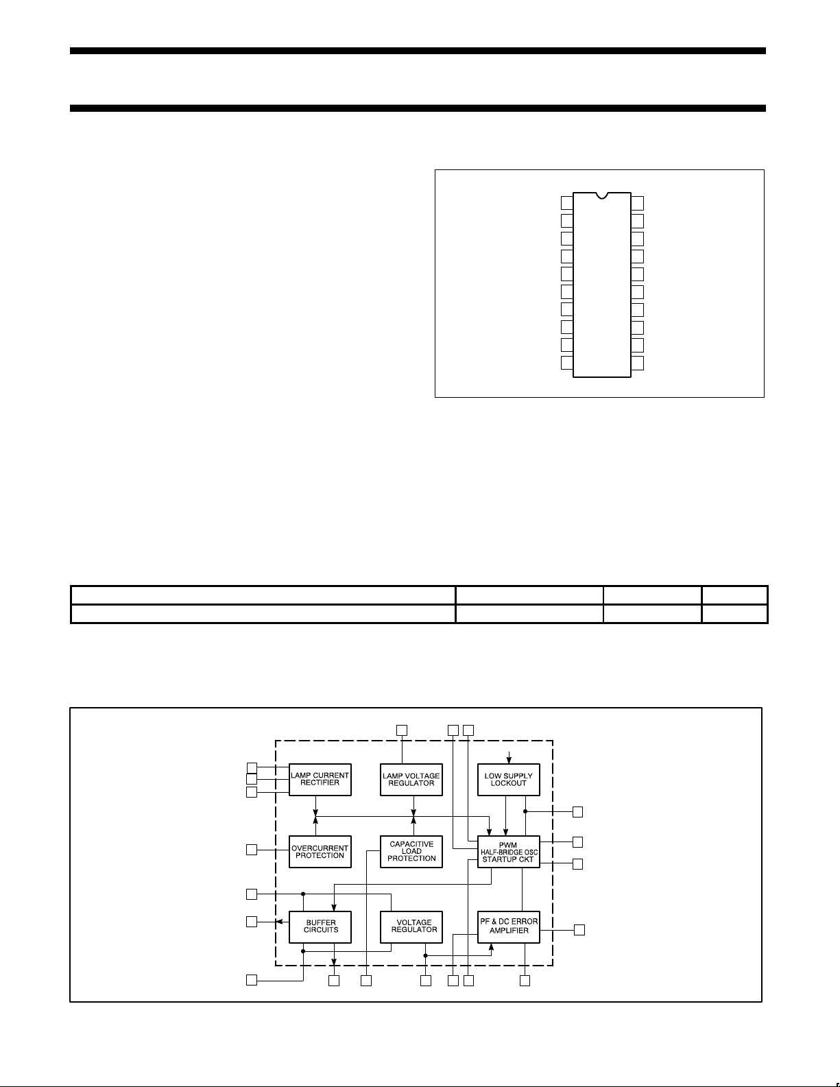
BLOCK DIAGRAM
7
8
9
10
11
12
3
2
1
20
13
14 15 16 17 18
56 4
19
C
RECT
LI2
LI
CSI
GND
OUT
P
V
CC
OUTHI
PRIM
V
REF
PF OV DC
DC
OUT
C
T
C
P
D
MAX
R
T
RXCX
V
LAMP
V
CC
SL00525
Figure 2. Block Diagram

Philips Semiconductors Product specification
NE5565Electronic ballast controller circuit
1996 May 21
2
13 17 12 10 11 19 18 14 6 15
5 16 4 3 2 1 20 7 9 8
AC
LINE
AC
FILTER
DC
SUPPLY
POWER FACTOR
CORRECTION
CIRCUIT
HALF-BRIDGE
SQUARE WAVE
OSCILLATOR
FLUORESCENT LAMPS
DIMMING
INPUT
V
CC
C
RECT
LI2LI
CSI GND
OUT
P
OUT
H
I
PRIM
V
REF
PF OVDC
DC
OUT
C
T
C
P
D
MAX
R
T
RXCX
V
LAMP
R
5
R
4
R
X
C
X
R
T
R
1
C
1
R
2
C
P
C
T
C
2
C
3
R
3
SL00526
Figure 3. Typical Application: 2-Lamps Dimming Ballast
Voltage Regulator
The V
REF
output provides a regulated output voltage of 7.42V at the
V
REF
pin. This voltage is used as a reference as well as the power
supply of the control logic. It is based on a trimmed band gap
voltage reference circuit. The nominal V
CC
voltage for the control
chip is 12.7V. The V
REF
circuit requires a minimum of 9.3V before it
can produce regulated output. The V
REF
output voltage has an
absolute accuracy of ±3.5% over the temperature range of 0°C to
85°C.
Lamp Voltage Regulator
Limits the maximum open circuit voltage across the lamp load during
the pre-heat, ignition and lamp removal conditions. During steady
state operation, the lamp voltage is governed by the arc voltage of
the lamps, not by the control circuit. The lamp voltage comparator is
used to sense when the voltage at the V
LAMP
pin exceeds V
REF
. At
the time this occurs, the lamp voltage has reached its maximum
allowed open circuit value and the circuit responds by producing a
rapid frequency increase which reduces the voltage at the Vlamp
pin. The RxCx time constant sets the frequency sweep time of the
start up circuit. The frequency sweep range has a rate of 2:1.
Low Supply Lock-out Protection
Senses the DC power supply voltage at the VCC pin to determine
when the PFC and half-bridge control circuits should turn on or off.
This protection circuit uses a Schmitt trigger with a voltage reference
to determine the upper and lower trip points of the power supply
voltage. As the power supply voltage rises from 0V to a value just
below the upper trip point of 11V, both the PFC and the half-bridge
control circuits are held in the off state. Once the V
CC
voltage rises
above the upper trip point, both PFC and half-bridge oscillator
circuits become operational. When the V
CC
falls below the lower
trip point of 10V, both PFC and half-bridge circuits are disabled.
Once the half-bridge oscillator turns off, it is not allowed to turn back
on until V
CC
exceeds the upper trip point and a minimum time delay,
set by external components at the D
MAX
pin, has passed.
Start up Ckt
The Low Half-bridge Voltage Lock-out Circuit senses the DC output
voltage of the PFC SMPS clrcuit. It is used to inhibit the lamp
ignition sequence or frequency sweep of the half-bridge oscillator
until the PFC output voltage has reached a pre-determined value.
This value is set by external components. The PFC voltage is
sensed by the over voltage input pin, OV . When this input exceeds
5/7 of V
REF
the frequency sweep is allowed to occur, thus beginning
the lamp ignition sequence.
The Over Voltage Protection Circuit prevents the PFC DC output
voltage from exceeding a pre-determined value. When the voltage
at the OV pin is greater than V
REF
the PFC buffer gate drive output
OUT
P
is turned off. This prevents any further increase in PFC DC
output voltage. The over voltage circuit only protects against an
over voltage or over shoot generated by the PFC itself. This may
occur during turn on when the SMPS is not loaded and the circuit is
under damped. Transient voltages from the AC line are not
suppressed by this circuit.
Capacitive Load Protection
Prevents failure of the half-bridge power transistors during lamp
removal. It does this by limiting the operation of the half-bridge
oscillator to frequencies above the resonant frequency of an
 Loading...