

Page 1

1,
Intercom Box
:
Y
4
. User manual
.
PHILIPS
Page 2
C‘%lOOOW~i~~-
020694
MONITOR
+I+
cL46610006/138
020694
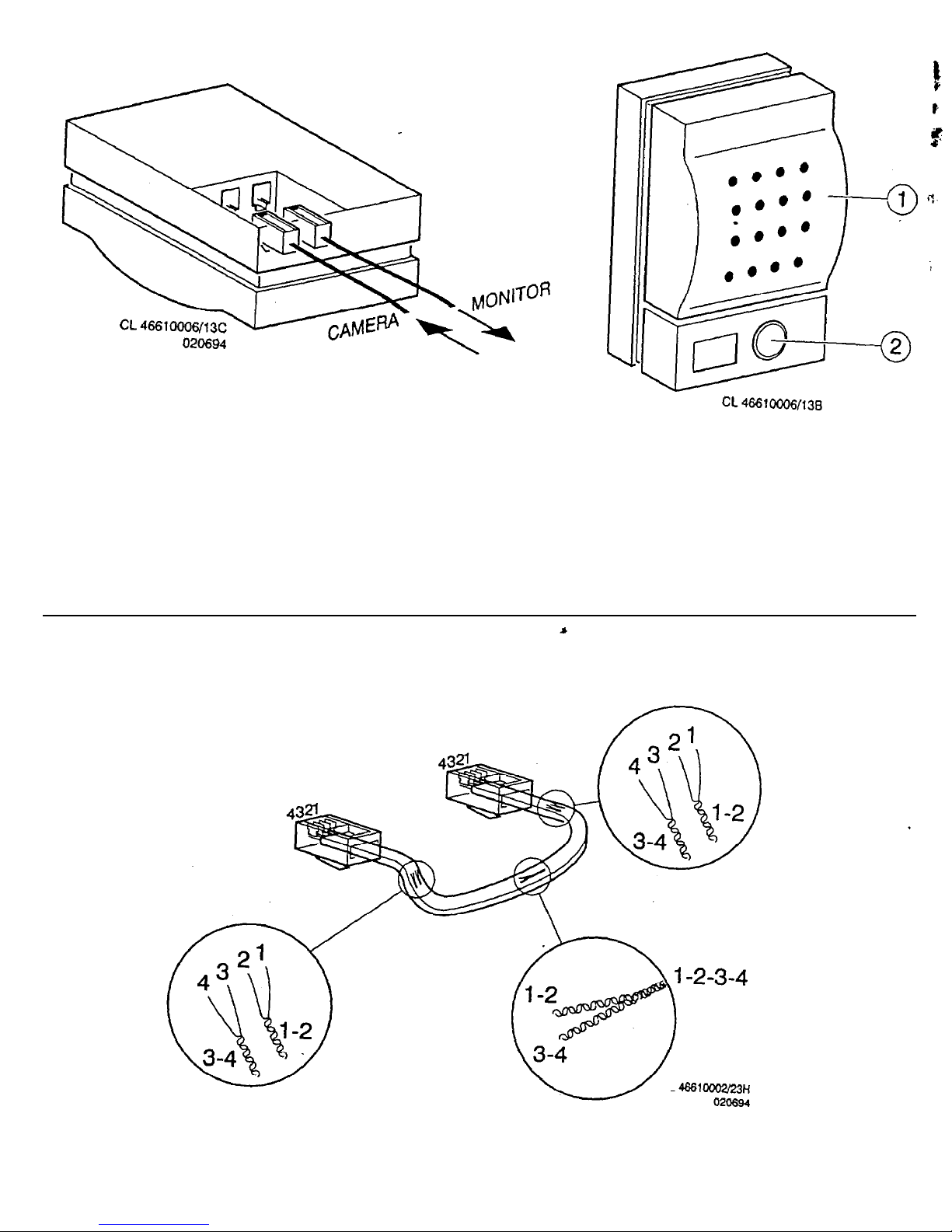
Figure
A
Figure B
CL
4661OOO2i231-1
Page 3

. Intercom Box
.
E
4
This device complies with part 15 of the FCC rules. Operation is subject
to the following two conditions:
1.
this device may not cause harmful interference, and
2.
this device must accept any interference received, including
interference that may cause undesired operation.
”
This device is intended to be attached to a receiver that is not used to
receive over-the-air broadcast signals. Connection of this device in any
other fashion may cause harmful interference to radio communications
.
and is in violation of the. FCC Rules, Part 15.
.
This device complies to FCC rules under test conditions that included
use of system cables and connectors between system components. If
you have any problems, contact your dealer.
WARNING:
To prevent fire or shock hazard, do not expose this accessory to
rain or moisture. Do not attempt to disassemble the accessory. In
order to prevent shock and fire hazard, do not remove screws or
covers. There are no user-serviceable parts inside.
The illustrations to which this
manual refers, are shown on the
.front
and back jacket flap.
Page 4

Operation
When the
Talk
button is pushed, the sound of the monitor’s
microphone is reproduced by the intercom box, which can be installed
in the camera-monitored area.
’ I
In the same way the sound of the intercom box microphone (fig. A-l)
(plus that of the camera, if not switched off) is reproduced by the
monitor. This is a particularly practical function when the system is
used.
a lot for access surveillance, for instance.
.
Doorbell: There is a push button (fig. A-,2) on the intercom box,
whicti
can be used as a doorbell.
When the button is pushed, a buzzer will sound at the monitor, after
which the picture is switched to the corresponding
camera.‘lf
the
automatic camera sequence is active, it will be stopped.
If the system operator
does
not react within 1
.minute
to the warning
signal by pushing
any.random
button, the monitor will return to its
previous status, or the automatic camera sequence is continued.
Installation
Warning:
When a camera or accessory is connected or disconnected,
the monitor should always be disconnected from the mains
_
supply.
Only operating the
stand-by
key is not sufficient.
When the mains supply is connected, all camera lines are scanned.
The monitor uses this to register the camera configuration of the
system and to check whether any modifications have been made.
2
.
Page 5

Cable
For
an optimum picture and sound quality a standard ‘twisted-pair’
.
(telephone) cable should be used.
There is an extensive range of plugs and tools available in the hobby
and professional trade to
extend
the cable. Always pay attention that
the connection corresponds to figure B.
Remark: Used system cables and connectors are similar to the ones
used for telephone. but may not be interconnected.
-
The maximum distance that can be bridged (without a cable extension
adapter) between the monitor and the cameras amounts to 200 meters
(150 meters for colour).
3
Page 6

Technical specification
IIVTERCOM
BOX
Call button
Audio output power
Power supply
Power consumption
System in/output
System cable
Dimensions
(W
x H x D)
Weight
Ambient conditions
temperature (Operating/Storage)
humidity (Operating/Storage)
Push type
160
mWatt
max.
22 V DC (via system cable)
maxIWatt.
RJ 11 E modular
“telephone” sockets
4wire
twisted pair
“telephone” cable
111
x73x38mm
135 gr
Ammonia resistent
+I 0 -
+45”C /
-25 -
+7O”C
20% -
90%RH / 99%RH
Specifications may be changed without notice.
 Loading...