

Philips IntelliVue TRx Instructions For Use Manual

IntelliVue TRx/TRx
+
Transceivers
for the Philips IntelliVue Telemetry System with
Smart-Hopping Technology
Notice
Operation of this equipment in the United States requires the prior coordindation with a frequency coordinator designated by the Federal Communications
Commission (FCC) for the Wireless Medical Telemetry Service.
Instructions for Use
Part Number: M4841-91001
Printed in the U.S.A. November 2004
First Edition

Printing History
Notice Equipment specifications are subject to alteration without notice. All changes
will be in compliance with regulations governing manufacture of medical
equipment.
Printed in the USA.
Document number: M4841-91001
© Copyright 2004 Koninklijke Philips Electronics N.V. All Rights Reserved.
OxiCliq and OxiMax are registered trademarks of Nellcor® Incorporated.
Printing History
New editions of this document will incorporate all material updated since the
previous edition. Update packages can be issued between editions and contain
replacement and additional pages to be merged by a revision date at the bottom
of the page. Note that pages which are rearranged due to changes on a previous
page are not considered revised.
The documentation printing date and part number indicate its current edition.
The printing date changes when a new edition is printed. (Minor corrections
and updates which are incorporated at reprint do not cause the date to change.)
The document part number changes when extensive technical changes are
incorporated.
First Edition ...............................................................................November 2004
Philips IntelliVue Telemetry System with Smart Hopping Technology is
compatible with:
Philips Information Center, software revision F.00
Philips TeleMon Companion Monitor, #A02/A03
ii

About this Book
This book contains operating instructions for use of the IntelliVue TRx and
TRx
Smart-hopping Technology. It also includes operational information for the
Telemetry functions of the IntelliVue Information Center. The intended
audience is the clinician who uses and/or teaches others to use the equipment
in a healthcare environment. For operating information on other functionality
of the Information Center, see IntelliVue Information Center Instructions for
Use. For preventive maintenance, repair, and test methods for verification of
device performance, refer to the Philips IntelliVue Telemetry System Service
Kit.
This book does not address the Philips M2601B Transmitter or the M2600B
Philips Telemetry System. For information on those products, refer to the
manual Philips Telemetry System Instructions for Use.
Note—Use this product in conjunction with Philips IntelliVue Information
Center Instructions for Use and Online Help, and with Philips TeleMon A02/
A03 Companion Monitor Instructions for Use. See also the Philips IntelliVue
Telemetry Training Program.
About this Book
+
Transceivers as used with the Philips IntelliVue Telemetry System with
Document
Conventions
Warnings
WarningWarning
Warnings are information you should know to avoid injuring patients and
personnel.
Cautions
Caution
Cautions are information you should know to avoid damaging your equipment
and software.
iii

Product Safety Information
Notes
Note—Notes contain additional information on use of the Philips IntelliVue
Telemetry System.
Procedures
Procedures are indicated in text by the heading “Task Summary” followed by
the following table:
Step
Action
1
2
3
Bold Typeface
Objects of actions in procedures appear in
example:
Select the
Standby button.
Product Safety Information
The following general warnings and cautions apply to use of the Philips
IntelliVue Transceivers in a Philips IntelliVue Wireless Network. Additional
warnings and cautions specific to a particular feature are provided in the
appropriate section.
bold typeface. Note the following
General
WarningWarning
For continued safe use of this equipment, it is necessary that the listed
instructions are followed. Instructions in this manual in no way supersede
established medical procedures.
iv

Product Safety Information
WarningWarning
Do not touch the patient, or table, or instruments, during defibrillation.
The battery door must be closed during defibrillation. These steps protect
the clinician from high defibrillator voltage.
WarningWarning
This device is not to be used in the vicinity of electrosurgical units because
use may interrupt or interfere with the transmission of signals from the
transceiver.
WarningWarning
This equipment is not suitable for use in the presence of a flammable
anesthetic mixture with air or with oxygen or nitrous oxide
WarningWarning
Do not use patient cables with detachable lead wires that have exposed
male pins. Electrocution could result if these pins are plugged into AC
power.
WarningWarning
Use of product accessories (e.g., ECG leadsets, SpO2 sensors) other than
those prescribed by Philips could lead to patient injury.
WarningWarning
To avoid strangulation, do not tie a pouch solely around the patient’s
neck.
v

Product Safety Information
ECG/
Arrhythmia All Patients
WarningWarning
ECG SAFETY FOR ALL PATIENTS
Always confirm Information Center observations with clinical
observation of the patient before administering interventions.
Every lead must be secured to an electrode on the patient.
Conductive parts of electrodes must not contact earth or other conductive
parts.
Philips recommends that you change the lead label only to reflect the
physical placement of electrodes. This will ensure a match between the
monitored lead and the label, and prevent any possible confusion.
When switching between EASI and standard monitoring, there is a loss of
data for 30 seconds.
vi

Product Safety Information
WarningWarning
ST/AR ARRHYTHMIA SAFETY FOR ALL PATIENTS
During complete heart block or pacemaker failure (to pace or capture),
tall P-waves (greater than 1/5 of the average R-wave height) can be
erroneously counted by the arrhythmia algorithm, resulting in missed
detection of cardiac arrest.
Learning/Relearning
- If you initiate learning during ventricular rhythm, the ectopics can be
incorrectly learned as the normal QRS complex. This can result in missed
detection of subsequent events of V-Tach and V-Fib.
- When using EASI ECG monitoring, Relearn happens automatically
when there is a LEADS OFF technical alarm. If learning takes place
during ventricular rhythm, the ectopics can be incorrectly learned as the
normal QRS complex. This can result in missed detection of subsequent
events of V-Tach and V-Fib. Be sure to check the beat labels and initiate a
relearn to correct. Therefore, when a technical alarm is generated:
1. Respond to the technical alarm [for example, reconnect the
electrode(s)].
2. Ensure that the arrhythmia algorithm is labeling beats correctly.
vii

Product Safety Information
ECG/
Arrhythmia Paced
Patients
WarningWarning
ECG SAFETY FOR PACED PATIENTS
The output power of the transceiver and other sources of radio frequency
energy, when used in the proximity of a pacemaker, can be sufficient to
interfere with pacemaker performance. Due to the shielding effects of the
body, internal pacemakers are somewhat less vulnerable than external
pacemakers. However, caution should be exercised when monitoring any
paced patient.
In order to minimize the possibility of interference, position electrodes,
electrode wires, and the transceiver as far away from the pacemaker as
possible.
Consult the pacemaker manufacturer for information on the RF
susceptibility of their products and the use of their products with the
Philips IntelliVue Telemetry System. See the IntelliVue Information Center
Instructions for Use for additional information on monitoring paced
patients.
viii

Product Safety Information
WarningWarning
ST/AR ARRHYTHMIA SAFETY FOR PACED PATIENTS
It is possible that pacemaker pulses will not be detected when the ECG
analog output of a defibrillator or telemetry unit is plugged into a bedside
monitor. This can result in the arrhythmia algorithm’s failure to detect
pacemaker non-capture or asystole.
Some pace pulses can be difficult to reject. When this happens, the pulses
are counted as a QRS complex, and could result in an incorrect HR and
failure to detect cardiac arrest or some arrhythmias. Keep pacemaker
patients under close observation.
-- During complete heart block or pacemaker failure (to pace or capture),
tall P-waves (greater than 1/5 of the average R-wave height) can be
erroneously counted by the arrhythmia algorithm, resulting in missed
detection of cardiac arrest.
-- When arrhythmia monitoring paced patients who exhibit only intrinsic
rhythm, the monitor can erroneously count pace pulses as QRS complexes
when the algorithm first encounters them, resulting in missed detection of
cardiac arrest.
For patients who exhibit intrinsic rhythm only, the risk of missing cardiac
arrest can be reduced by monitoring these patients with the low heart rate
limit at or slightly above the basic/demand pacemaker rate. A low heart
rate alarm alarms you when the patient begins pacing. Proper detection
and classification of the paced rhythm can then be determined.
-- When an external pacemaker is being used on a patient, arrhythmia
monitoring is severely compromised due to the high energy level in the
pacer pulse. This can result in the arrhythmia algorithm’s failure to
detect pacemaker non-capture or asystole.
ix

Product Safety Information
SpO
2
WarningWarning
SpO2 SAFETY
Always confirm Information Center observations with clinical
observation of the patient before administering interventions.
Prolonged, continuous monitoring can increase the risk of changes in skin
characteristics, such as irritation, reddening, blistering or pressure
necrosis, particularly on patients with impaired perfusion and varying or
immature skin morphology. Specific attention must be given to sensor site
inspection for changes in skin quality, proper optical path alignment and
attachment. Check the application site at regular intervals and change the
site if any compromise in skin quality should occur. More frequent
checking can be required due to an individual patient's condition.
Using a sensor during MR imaging can cause severe burns. To minimize
this risk, ensure that the cable is positioned so that no inductive loops are
formed. If the sensor does not appear to be operating properly, remove it
immediately from the patient.
Do not use disposable sensors on patients who exhibit allergic reactions to
the adhesive.
Injected dyes such as methylene blue or intravascular dyshemoglobins
such as methemoglobin and carboxyhemoglobin can lead to inaccurate
(over-estimated) measurements.
Interference leading to inaccurate measurements can be caused by:
- High levels of ambient light (Hint: cover application site with opaque
material)
- Electromagnetic interference
- Excessive patient movement and vibration.
x

Content s
General. . . . . . . . . . . . . . . . . . . . . . . . . . . . . . . . . . . . . . . . . . . . . . . . . . . . . . . . . . . . . . . . . 1-iv
ECG/ Arrhythmia -All Patients . . . . . . . . . . . . . . . . . . . . . . . . . . . . . . . . . . . . . . . . . . . . . . 1-vi
ECG/Arrhythmia - Paced Patients . . . . . . . . . . . . . . . . . . . . . . . . . . . . . . . . . . . . . . . . . . . 1-viii
SpO2. . . . . . . . . . . . . . . . . . . . . . . . . . . . . . . . . . . . . . . . . . . . . . . . . . . . . . . . . . . . . . . . . . . . 1-x
1. Basic Operation . . . . . . . . . . . . . . . . . . . . . . . . . . . . . . . . . . . . . . . . . . . . . . . . . 1-1
The Philips IntelliVue Telemetry System. . . . . . . . . . . . . . . . . . . . . . . . . . . . . . . . . . . . . . . . . . .1-2
System Features . . . . . . . . . . . . . . . . . . . . . . . . . . . . . . . . . . . . . . . . . . . . . . . . . . . . . . . . . . . 1-3
The IntelliVue Transceiver. . . . . . . . . . . . . . . . . . . . . . . . . . . . . . . . . . . . . . . . . . . . . . . . . . . . . . 1-3
Transceiver Controls - Front . . . . . . . . . . . . . . . . . . . . . . . . . . . . . . . . . . . . . . . . . . . . . . . . . 1-7
Transceiver Controls - Back . . . . . . . . . . . . . . . . . . . . . . . . . . . . . . . . . . . . . . . . . . . . . . . . 1-11
Turning the Transceiver On . . . . . . . . . . . . . . . . . . . . . . . . . . . . . . . . . . . . . . . . . . . . . . . . . . . . 1-15
Turning the Transceiver Off . . . . . . . . . . . . . . . . . . . . . . . . . . . . . . . . . . . . . . . . . . . . . . . . 1-16
Testing intelliVue Transceiver Functionality . . . . . . . . . . . . . . . . . . . . . . . . . . . . . . . . . . . . . . . 1-17
Self Test . . . . . . . . . . . . . . . . . . . . . . . . . . . . . . . . . . . . . . . . . . . . . . . . . . . . . . . . . . . . . . . . 1-17
Status Check. . . . . . . . . . . . . . . . . . . . . . . . . . . . . . . . . . . . . . . . . . . . . . . . . . . . . . . . . . . . .1-18
Battery Information. . . . . . . . . . . . . . . . . . . . . . . . . . . . . . . . . . . . . . . . . . . . . . . . . . . . . . . . . . .1-19
Battery Safety Information. . . . . . . . . . . . . . . . . . . . . . . . . . . . . . . . . . . . . . . . . . . . . . . . . .1-19
Inserting/Removing Batteries . . . . . . . . . . . . . . . . . . . . . . . . . . . . . . . . . . . . . . . . . . . . . . . 1-20
Checking the Battery Power Level . . . . . . . . . . . . . . . . . . . . . . . . . . . . . . . . . . . . . . . . . . . 1-22
Briefing the Patient . . . . . . . . . . . . . . . . . . . . . . . . . . . . . . . . . . . . . . . . . . . . . . . . . . . . . . . . . . . 1-24
Pouch Use . . . . . . . . . . . . . . . . . . . . . . . . . . . . . . . . . . . . . . . . . . . . . . . . . . . . . . . . . . . . . .1-24
Securing the Pouch. . . . . . . . . . . . . . . . . . . . . . . . . . . . . . . . . . . . . . . . . . . . . . . . . . . . . . . .1-25
Showering . . . . . . . . . . . . . . . . . . . . . . . . . . . . . . . . . . . . . . . . . . . . . . . . . . . . . . . . . . . . . . 1-26
Transceiver Use with TeleMon A02/A03. . . . . . . . . . . . . . . . . . . . . . . . . . . . . . . . . . . . . . . . . .1-27
2. Alarms. . . . . . . . . . . . . . . . . . . . . . . . . . . . . . . . . . . . . . . . . . . . . . . . . . . . . . . . . 2-1
Alarm Indicators . . . . . . . . . . . . . . . . . . . . . . . . . . . . . . . . . . . . . . . . . . . . . . . . . . . . . . . . . . . . . . 2-2
Testing Alarm Indicators. . . . . . . . . . . . . . . . . . . . . . . . . . . . . . . . . . . . . . . . . . . . . . . . . . . . 2-2
Suspending/Pausing Alarms . . . . . . . . . . . . . . . . . . . . . . . . . . . . . . . . . . . . . . . . . . . . . . . . . . . . .2-2
Resuming/ Unsuspending Alarms . . . . . . . . . . . . . . . . . . . . . . . . . . . . . . . . . . . . . . . . . . . . . 2-4
Standby Mode . . . . . . . . . . . . . . . . . . . . . . . . . . . . . . . . . . . . . . . . . . . . . . . . . . . . . . . . . . . . . . . . 2-5
Alarm Behavior with Own Bed Overview . . . . . . . . . . . . . . . . . . . . . . . . . . . . . . . . . . . . . . . . . . 2-7
Physiologic Alarms. . . . . . . . . . . . . . . . . . . . . . . . . . . . . . . . . . . . . . . . . . . . . . . . . . . . . . . . . . . .2-9
Technical Alarms (INOPs) . . . . . . . . . . . . . . . . . . . . . . . . . . . . . . . . . . . . . . . . . . . . . . . . . . . . . 2-14
Contents-1

3. ECG Monitoring . . . . . . . . . . . . . . . . . . . . . . . . . . . . . . . . . . . . . . . . . . . . . . . . . 3-1
ECG Safety Information . . . . . . . . . . . . . . . . . . . . . . . . . . . . . . . . . . . . . . . . . . . . . . . . . . . . . . . .3-2
Measuring ECG. . . . . . . . . . . . . . . . . . . . . . . . . . . . . . . . . . . . . . . . . . . . . . . . . . . . . . . . . . . . . . .3-3
EASI ECG . . . . . . . . . . . . . . . . . . . . . . . . . . . . . . . . . . . . . . . . . . . . . . . . . . . . . . . . . . . . . . .3-3
ECG Leadsets. . . . . . . . . . . . . . . . . . . . . . . . . . . . . . . . . . . . . . . . . . . . . . . . . . . . . . . . . . . . .3-3
ECG Leads Monitored. . . . . . . . . . . . . . . . . . . . . . . . . . . . . . . . . . . . . . . . . . . . . . . . . . . . . . 3-4
Positioning ECG Electrodes. . . . . . . . . . . . . . . . . . . . . . . . . . . . . . . . . . . . . . . . . . . . . . . . . . . . . 3-8
Electrode Placement. . . . . . . . . . . . . . . . . . . . . . . . . . . . . . . . . . . . . . . . . . . . . . . . . . . . . . .3-10
Connecting the ECG Cable. . . . . . . . . . . . . . . . . . . . . . . . . . . . . . . . . . . . . . . . . . . . . . . . . . . . .3-19
Verifying Electrode Connections . . . . . . . . . . . . . . . . . . . . . . . . . . . . . . . . . . . . . . . . . . . . . . . .3-22
Monitoring during Leads Off . . . . . . . . . . . . . . . . . . . . . . . . . . . . . . . . . . . . . . . . . . . . . . . . . . .3-23
ECG Fallback. . . . . . . . . . . . . . . . . . . . . . . . . . . . . . . . . . . . . . . . . . . . . . . . . . . . . . . . . . . .3-23
Extended Monitoring . . . . . . . . . . . . . . . . . . . . . . . . . . . . . . . . . . . . . . . . . . . . . . . . . . . . . .3-24
Relearning . . . . . . . . . . . . . . . . . . . . . . . . . . . . . . . . . . . . . . . . . . . . . . . . . . . . . . . . . . . . . .3-24
Using EASI Leads to Troubleshoot. . . . . . . . . . . . . . . . . . . . . . . . . . . . . . . . . . . . . . . . . . .3-24
Optimizing ECG Measurement Performance . . . . . . . . . . . . . . . . . . . . . . . . . . . . . . . . . . . . . . .3-25
The Telemetry Signal. . . . . . . . . . . . . . . . . . . . . . . . . . . . . . . . . . . . . . . . . . . . . . . . . . . . . . 3-25
Trouble- shooting Signal Disturbances . . . . . . . . . . . . . . . . . . . . . . . . . . . . . . . . . . . . . . . .3-26
Dropouts. . . . . . . . . . . . . . . . . . . . . . . . . . . . . . . . . . . . . . . . . . . . . . . . . . . . . . . . . . . . . . . .3-26
Muscle and Movement Artifact . . . . . . . . . . . . . . . . . . . . . . . . . . . . . . . . . . . . . . . . . . . . . . 3-27
4. ST/AR Arrhythmia & ST Segment Monitoring. . . . . . . . . . . . . . . . . . . . . . . . 4-1
ST/AR Arrhythmia Algorithm . . . . . . . . . . . . . . . . . . . . . . . . . . . . . . . . . . . . . . . . . . . . . . . . . . .4-2
Safety Information . . . . . . . . . . . . . . . . . . . . . . . . . . . . . . . . . . . . . . . . . . . . . . . . . . . . . . . . .4-2
ST/AR Arrhythmia Analysis . . . . . . . . . . . . . . . . . . . . . . . . . . . . . . . . . . . . . . . . . . . . . . . . . 4-3
ST/AR ST Segment Algorithm. . . . . . . . . . . . . . . . . . . . . . . . . . . . . . . . . . . . . . . . . . . . . . . . . . .4-6
The Measurement. . . . . . . . . . . . . . . . . . . . . . . . . . . . . . . . . . . . . . . . . . . . . . . . . . . . . . . . . .4-6
Algorithm Processing. . . . . . . . . . . . . . . . . . . . . . . . . . . . . . . . . . . . . . . . . . . . . . . . . . . . . . .4-8
Displayed ST Data. . . . . . . . . . . . . . . . . . . . . . . . . . . . . . . . . . . . . . . . . . . . . . . . . . . . . . . . . 4-8
EASI ST Analysis . . . . . . . . . . . . . . . . . . . . . . . . . . . . . . . . . . . . . . . . . . . . . . . . . . . . . . . . .4-8
ST Operation . . . . . . . . . . . . . . . . . . . . . . . . . . . . . . . . . . . . . . . . . . . . . . . . . . . . . . . . . . . . .4-9
ST Alarm Settings . . . . . . . . . . . . . . . . . . . . . . . . . . . . . . . . . . . . . . . . . . . . . . . . . . . . . . . .4-11
5. SpO2 Monitoring . . . . . . . . . . . . . . . . . . . . . . . . . . . . . . . . . . . . . . . . . . . . . . . .5-1
SpO2 Safety Information . . . . . . . . . . . . . . . . . . . . . . . . . . . . . . . . . . . . . . . . . . . . . . . . . . . . . . .5-2
SpO2 Information for the User . . . . . . . . . . . . . . . . . . . . . . . . . . . . . . . . . . . . . . . . . . . . . . .5-3
Pulse Oximetry Measurement. . . . . . . . . . . . . . . . . . . . . . . . . . . . . . . . . . . . . . . . . . . . . . . . . . . .5-4
Pulse Indication . . . . . . . . . . . . . . . . . . . . . . . . . . . . . . . . . . . . . . . . . . . . . . . . . . . . . . . . . . . 5-5
Selecting a SpO2 Sensor. . . . . . . . . . . . . . . . . . . . . . . . . . . . . . . . . . . . . . . . . . . . . . . . . . . . . . . . 5-5
Applying the Sensor. . . . . . . . . . . . . . . . . . . . . . . . . . . . . . . . . . . . . . . . . . . . . . . . . . . . . . . . . . .5-9
Contents-2

Sensor Application Safety Information . . . . . . . . . . . . . . . . . . . . . . . . . . . . . . . . . . . . . . . . .5-9
Site Selection . . . . . . . . . . . . . . . . . . . . . . . . . . . . . . . . . . . . . . . . . . . . . . . . . . . . . . . . . . . . .5-9
Sensor Application . . . . . . . . . . . . . . . . . . . . . . . . . . . . . . . . . . . . . . . . . . . . . . . . . . . . . . . .5-10
Connecting the SpO2 Cable. . . . . . . . . . . . . . . . . . . . . . . . . . . . . . . . . . . . . . . . . . . . . . . . . . . . .5-14
Measuring SpO
2. . . . . . . . . . . . . . . . . . . . . . . . . . . . . . . . . . . . . . . . . . . . . . . . . . . . . . . . . . . . . . . . . . . . . . . . . . . . . . 5-15
Spot Check . . . . . . . . . . . . . . . . . . . . . . . . . . . . . . . . . . . . . . . . . . . . . . . . . . . . . . . . . . . . . .5-15
Continuous. . . . . . . . . . . . . . . . . . . . . . . . . . . . . . . . . . . . . . . . . . . . . . . . . . . . . . . . . . . . . .5-16
SpO
Measurement when Connected to TeleMon . . . . . . . . . . . . . . . . . . . . . . . . . . . . . . . .5-17
2
Turning SpO2 Monitoring Off . . . . . . . . . . . . . . . . . . . . . . . . . . . . . . . . . . . . . . . . . . . . . . .5-18
Turning the SpO2 Parameter On/Off . . . . . . . . . . . . . . . . . . . . . . . . . . . . . . . . . . . . . . . . . .5-19
SpO
Parameter Auto ON. . . . . . . . . . . . . . . . . . . . . . . . . . . . . . . . . . . . . . . . . . . . . . . . . . .5-19
2
Understanding SpO2 Alarms. . . . . . . . . . . . . . . . . . . . . . . . . . . . . . . . . . . . . . . . . . . . . . . . . . . .5-20
Optimizing SpO2 Measurement Performance. . . . . . . . . . . . . . . . . . . . . . . . . . . . . . . . . . . . . . .5-21
Optimizing Sensor Performance. . . . . . . . . . . . . . . . . . . . . . . . . . . . . . . . . . . . . . . . . . . . . .5-22
6. Telemetry Functions at the Information Center . . . . . . . . . . . . . . . . . . . . . . . 6-1
Telemetry Controls in the Patient Window . . . . . . . . . . . . . . . . . . . . . . . . . . . . . . . . . . . . . . . . . .6-2
Locating the Transceiver (Find Device) . . . . . . . . . . . . . . . . . . . . . . . . . . . . . . . . . . . . . . . . . . . .6-3
To locate a transceiver . . . . . . . . . . . . . . . . . . . . . . . . . . . . . . . . . . . . . . . . . . . . . . . . . . . . . .6-3
To silence the sound . . . . . . . . . . . . . . . . . . . . . . . . . . . . . . . . . . . . . . . . . . . . . . . . . . . . . . .6-3
Patient-Configurable Settings in Telemetry Setup . . . . . . . . . . . . . . . . . . . . . . . . . . . . . . . . . . . .6-3
Unit-Configurable Settings . . . . . . . . . . . . . . . . . . . . . . . . . . . . . . . . . . . . . . . . . . . . . . . . . . . . . .6-7
. . . . . . . . . . . . . . . . . . . . . . . . . . . . . . . . . . . . . . . . . . . . . . . . . . . . . . . . . . . . . . . . . . . . . . . .6-8
7. Maintenance & Troubleshooting . . . . . . . . . . . . . . . . . . . . . . . . . . . . . . . . . . . 7-1
Maintenance. . . . . . . . . . . . . . . . . . . . . . . . . . . . . . . . . . . . . . . . . . . . . . . . . . . . . . . . . . . . . . . . . .7-2
Basic Monitoring . . . . . . . . . . . . . . . . . . . . . . . . . . . . . . . . . . . . . . . . . . . . . . . . . . . . . . . . . .7-2
Label Assignment for Replacement Transceiver . . . . . . . . . . . . . . . . . . . . . . . . . . . . . . . . . .7-2
Transceiver Cleaning, Disinfection, & Cross-Infection Prevention . . . . . . . . . . . . . . . . . . . . . . .7-4
Cleaning the Transceiver . . . . . . . . . . . . . . . . . . . . . . . . . . . . . . . . . . . . . . . . . . . . . . . . . . . .7-5
Disinfecting the Transceiver. . . . . . . . . . . . . . . . . . . . . . . . . . . . . . . . . . . . . . . . . . . . . . . . . .7-6
Cross-Infection Prevention for the Transceiver . . . . . . . . . . . . . . . . . . . . . . . . . . . . . . . . . . .7-7
Troubleshooting . . . . . . . . . . . . . . . . . . . . . . . . . . . . . . . . . . . . . . . . . . . . . . . . . . . . . . . . . . . . . .7-15
Basic Troubleshooting . . . . . . . . . . . . . . . . . . . . . . . . . . . . . . . . . . . . . . . . . . . . . . . . . . . . .7-15
Testing Alarms . . . . . . . . . . . . . . . . . . . . . . . . . . . . . . . . . . . . . . . . . . . . . . . . . . . . . . . . . . .7-15
Information Signals. . . . . . . . . . . . . . . . . . . . . . . . . . . . . . . . . . . . . . . . . . . . . . . . . . . . . . . .7-15
8. Safety Standards & Specifications . . . . . . . . . . . . . . . . . . . . . . . . . . . . . . . . . .8-1
Regulatory Information . . . . . . . . . . . . . . . . . . . . . . . . . . . . . . . . . . . . . . . . . . . . . . . . . . . . . . . . .8-2
Intended Use. . . . . . . . . . . . . . . . . . . . . . . . . . . . . . . . . . . . . . . . . . . . . . . . . . . . . . . . . . . . . .8-2
Contents-3

Indications for Use. . . . . . . . . . . . . . . . . . . . . . . . . . . . . . . . . . . . . . . . . . . . . . . . . . . . . . . . . 8-2
Rx. . . . . . . . . . . . . . . . . . . . . . . . . . . . . . . . . . . . . . . . . . . . . . . . . . . . . . . . . . . . . . . . . . . . . . 8-2
Patient Population . . . . . . . . . . . . . . . . . . . . . . . . . . . . . . . . . . . . . . . . . . . . . . . . . . . . . . . . . 8-2
Safety Standards. . . . . . . . . . . . . . . . . . . . . . . . . . . . . . . . . . . . . . . . . . . . . . . . . . . . . . . . . . .8-2
Essential Performance . . . . . . . . . . . . . . . . . . . . . . . . . . . . . . . . . . . . . . . . . . . . . . . . . . . . . .8-3
System Classification. . . . . . . . . . . . . . . . . . . . . . . . . . . . . . . . . . . . . . . . . . . . . . . . . . . . . . .8-3
FCC Compliance (USA only) . . . . . . . . . . . . . . . . . . . . . . . . . . . . . . . . . . . . . . . . . . . . . . . .8-4
AC Power Source. . . . . . . . . . . . . . . . . . . . . . . . . . . . . . . . . . . . . . . . . . . . . . . . . . . . . . . . . . 8-5
Battery Life Specifications . . . . . . . . . . . . . . . . . . . . . . . . . . . . . . . . . . . . . . . . . . . . . . . . . . . . . .8-5
Electromagnetic Compatibility . . . . . . . . . . . . . . . . . . . . . . . . . . . . . . . . . . . . . . . . . . . . . . . . . . .8-6
Restrictions for Use . . . . . . . . . . . . . . . . . . . . . . . . . . . . . . . . . . . . . . . . . . . . . . . . . . . . . . . .8-8
Radio Specifications . . . . . . . . . . . . . . . . . . . . . . . . . . . . . . . . . . . . . . . . . . . . . . . . . . . . . . . . . . .8-8
M4841A Transceiver . . . . . . . . . . . . . . . . . . . . . . . . . . . . . . . . . . . . . . . . . . . . . . . . . . . . . . .8-8
WMTS Channel Frequencies. . . . . . . . . . . . . . . . . . . . . . . . . . . . . . . . . . . . . . . . . . . . . . . .8-10
Physical Specifications . . . . . . . . . . . . . . . . . . . . . . . . . . . . . . . . . . . . . . . . . . . . . . . . . . . . . . . .8-11
ECG-only Transceiver . . . . . . . . . . . . . . . . . . . . . . . . . . . . . . . . . . . . . . . . . . . . . . . . . . . . .8-11
ECG/SpO2 Transceiver . . . . . . . . . . . . . . . . . . . . . . . . . . . . . . . . . . . . . . . . . . . . . . . . . . . .8-12
Environmental Specifications . . . . . . . . . . . . . . . . . . . . . . . . . . . . . . . . . . . . . . . . . . . . . . . . . . .8-12
M4841A Transceiver . . . . . . . . . . . . . . . . . . . . . . . . . . . . . . . . . . . . . . . . . . . . . . . . . . . . . .8-12
Measurement Specifications . . . . . . . . . . . . . . . . . . . . . . . . . . . . . . . . . . . . . . . . . . . . . . . . . . .8-13
ECG . . . . . . . . . . . . . . . . . . . . . . . . . . . . . . . . . . . . . . . . . . . . . . . . . . . . . . . . . . . . . . . . . . .8-13
SpO2. . . . . . . . . . . . . . . . . . . . . . . . . . . . . . . . . . . . . . . . . . . . . . . . . . . . . . . . . . . . . . . . . . . 8-15
SpO2 Sensor Accuracy . . . . . . . . . . . . . . . . . . . . . . . . . . . . . . . . . . . . . . . . . . . . . . . . . . . .8-16
A. Accessory List. . . . . . . . . . . . . . . . . . . . . . . . . . . . . . . . . . . . . . . . . . . . . . . . . . A-1
Accessory Safety. . . . . . . . . . . . . . . . . . . . . . . . . . . . . . . . . . . . . . . . . . . . . . . . . . . . . . . . . . . . . A-2
ECG Accessories. . . . . . . . . . . . . . . . . . . . . . . . . . . . . . . . . . . . . . . . . . . . . . . . . . . . . . . . . . . . . A-2
Electrodes. . . . . . . . . . . . . . . . . . . . . . . . . . . . . . . . . . . . . . . . . . . . . . . . . . . . . . . . . . . . . . . A-2
Leadsets . . . . . . . . . . . . . . . . . . . . . . . . . . . . . . . . . . . . . . . . . . . . . . . . . . . . . . . . . . . . . . . . A-2
Trunk Cables . . . . . . . . . . . . . . . . . . . . . . . . . . . . . . . . . . . . . . . . . . . . . . . . . . . . . . . . . . . . A-3
Pouches . . . . . . . . . . . . . . . . . . . . . . . . . . . . . . . . . . . . . . . . . . . . . . . . . . . . . . . . . . . . . . . . A-3
Skin Prep Paper . . . . . . . . . . . . . . . . . . . . . . . . . . . . . . . . . . . . . . . . . . . . . . . . . . . . . . . . . . A-3
Alignment Guides . . . . . . . . . . . . . . . . . . . . . . . . . . . . . . . . . . . . . . . . . . . . . . . . . . . . . . . . A-4
Gunk Guards . . . . . . . . . . . . . . . . . . . . . . . . . . . . . . . . . . . . . . . . . . . . . . . . . . . . . . . . . . . . A-4
SpO2 Accessories . . . . . . . . . . . . . . . . . . . . . . . . . . . . . . . . . . . . . . . . . . . . . . . . . . . . . . . . . . . . A-4
Reusable Sensors . . . . . . . . . . . . . . . . . . . . . . . . . . . . . . . . . . . . . . . . . . . . . . . . . . . . . . . . . A-4
Disposable Sensors - Single Use . . . . . . . . . . . . . . . . . . . . . . . . . . . . . . . . . . . . . . . . . . . . . A-5
Wristband. . . . . . . . . . . . . . . . . . . . . . . . . . . . . . . . . . . . . . . . . . . . . . . . . . . . . . . . . . . . . . . A-6
B. Sales and Support Offices . . . . . . . . . . . . . . . . . . . . . . . . . . . . . . . . . . . . . . . . B-1
Contents-4

1
Basic Operation
This chapter introduces the Philips IntelliVue Telemetry System with Smarthopping Technology and the IntelliVue TRx and TRx
the following sections:
• The Philips IntelliVue Telemetry System. . . . . . . . . . . . . . . . . . . . . . . 1-2
• The IntelliVue Transceiver. . . . . . . . . . . . . . . . . . . . . . . . . . . . . . . . . . 1-3
• Turning the Transceiver On . . . . . . . . . . . . . . . . . . . . . . . . . . . . . . . . 1-15
• Testing intelliVue Transceiver Functionality . . . . . . . . . . . . . . . . . . . 1-17
• Battery Information. . . . . . . . . . . . . . . . . . . . . . . . . . . . . . . . . . . . . . . 1-19
• Pouch Use. . . . . . . . . . . . . . . . . . . . . . . . . . . . . . . . . . . . . . . . . . . . . .1-24
• Transceiver Use with TeleMon A02/A03. . . . . . . . . . . . . . . . . . . . . . 1-27
• Transceiver Use with TeleMon A02/A03. . . . . . . . . . . . . . . . . . . . . . 1-27
+
Transceivers. It includes
Introduction
Basic Operation 1-1

The Philips IntelliVue Telemetry System
The Philips IntelliVue Telemetry System
The Philips IntelliVue Telemetry System with Smart-hopping Technology
provides ambulatory and bedside monitoring of ECG and SpO
the radio frequency (RF) spectrum newly allocated for medical telemetry
applications by the Federal Communications Commission (FCC). The System
enables clinically significant data and control information for adult and pediatric
patients in healthcare facilities to be received from and sent to the transceiver, a
patient-worn device, via a bi-directional RF link over the Wireless Medical
Telemetry Service (WMTS) spectrums 1395-1400 MHz and 1427-1432 MHz.
The System uses smart-hopping technology to dynamically manage the RF
spectrum utilization per transceiver, thus allowing a virtually unlimited number
of simultaneously operating transceivers within the Philips IntelliVue Telemetry
System. The frequency-agile system changes frequency without user
involvement or awareness whenever interference occurs.
The System encompasses a number of individual units which connect together to
form a complete method of transporting ambulatory patient data to a central
repository for subsequent distribution to clinical staff. An installation typically
consists of the following components:
parameters over
2
1-2 Basic Operation
• M4841A Transceivers, bi-directional patient-worn devices
• M4842A Access Points (AP), centers for bidirectional communication
between the transceivers and the Information Center.
• IntelliVue Wireless Network (IWN) infrastructure (including M4843A
Access Point Controllers, M4844A Sync Units, M4845A Power Supply
Units)
• M3150A IntelliVue Information Center for centralized monitoring
• M3154A IntelliVue Database Server (optional) for centralized data
management
• M2636A TeleMon A02/A03 Companion Monitor (optional) for local
display, NBP measurement and local alarms.
The network interconnects Access Points to the Information Center and other
central equipment via the same network that connects IntelliVue bedsides to the
Information Center. Access points receive signals, and unlike traditional antenna
systems, can communicate bidirectionally. Access Points are powered,
controlled and managed remotely via the IWN.

The IntelliVue Transceiver
System
Features
• Full patient mobility within the areas defined by the wireless coverage
provided by multiple Access Points.
• Expanded geographic coverage area for a a given patient assigned to an
IntelliVue Clinical Network. Physiological data is transported from the
transceiver; a reverse data channel enables data to be transported to the
transceiver.
• 3-minute Alarm Pause/Suspend initiated at the transceiver.
• Standby mode when a patient is away from the unit and not being
monitored by the Philips IntelliVue Telemetry System.
• Find Device feature for locating a lost transceiver within the coverage
area.
• Access Points operating concurrently with the networked bedside wireless
capability while sharing some of the ICN infrastructure.
• Use of the radio spectrums newly allocated by the FCC specifically for
medical telemetry applications.
• Connectivity to TeleMon for display of patient measurements - including
NBP - at the bedside.
diagram to come
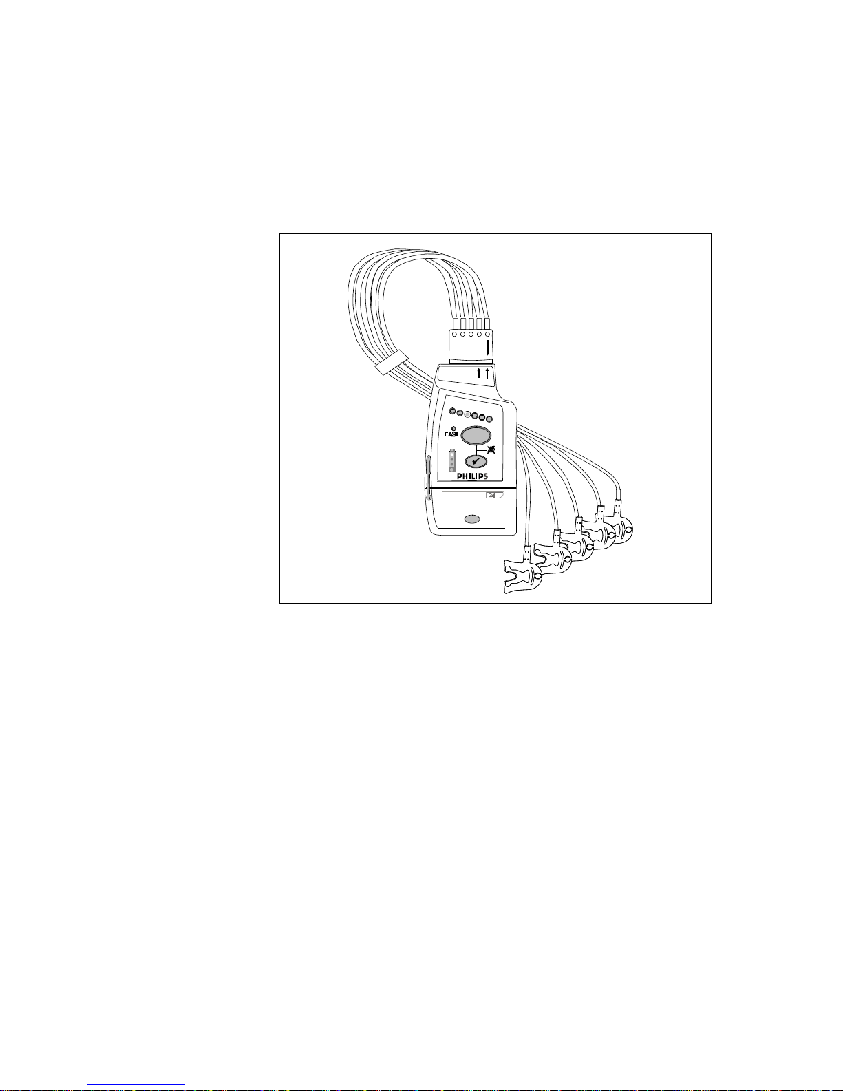
The IntelliVue Transceiver
The Philips IntelliVue transceiver is a patient-worm device for monitoring ECG
and SpO
System Information Flow/Smart-hopping
on adult and pediatric patients in the IntelliVue Telemetry System
2
Basic Operation
1-3

The IntelliVue Transceiver
with Smart-Hopping Technology, a cellular infrastructure network. The
transceiver combines traditional transmitter features with two-way
communication capability with the IntelliVue Information Center. The
transceiver is designed to be easy for clinicians to use and comfortable for
patients to wear. Colored labels provide departmental identifiers. The leadsets
are optimized for ambulating patients, with a cable length of 79 cm (30 inches).
Protective covers prevent dirt from accessing unused ECG and SpO
thus simplifying cleaning.
cable ports,
2
The transceiver is available in two models, the ECG only called the IntelliVue
TRx, and the ECG-SPO2 version, called the IntelliVue TRx
+
. The models are
listed below and illustrated on the following pages in this chapter. Subsequent
tables describe the buttons, indicators, labels, ports, safety symbols & other
markings, and auditory information signals of the transceiver respectively.
Transceiver Model
(M4841A) Measurements
IntelliVue TRx ECG
IntelliVue TRx
+
ECG, SpO
2
The transceiver comes with a start-up kit of batteries, electrodes, and pouches.
1-4 Basic Operation
M2601B
IntelliVue TRx
IntelliVue TRx
M4841A
M4841A
+
+
EASI, 3
EASI, 3
The IntelliVue Transceiver
5
5,6
Transceiver
Features
IntelliVue TRx Transceiver - ECG only
Note— The IntelliVue Transceiver and M2601B Transmitter are similar in
appearance. If your hospital uses both, you can distinguish between them by:
• Name on the front of the device
• Label background color (pale gray for transceivers, dark gray for
transmitters)
• Clinician-selectable 5-lead Standard or EASI leads in same device, at the
bedside
• 6-leadset with two V leads for diagnosing multiple cardiac abnormalities,
including wide-QRS complex tachycardias and acute myocardial
ischemia/infarction
• Powered by two AA Alkaline batteries
• Spot-Check SpO
without using any control buttons
2
Basic Operation
1-5

The IntelliVue Transceiver
•FAST-SpO2 (Fourier Artifact Suppression Technology) for improved
motion artifact rejection and low-perfusion performance
• Audio feedback for Spot Check SpO
completion and other common tasks
2
• Simultaneous operation in system with M2601A Transmitter
• Two sizes - smaller ECG only version and larger ECG/SpO
version
2
• Battery gauge on transceiver and, if configured, at Information Center
• Colored labels provide clinical unit identifiers.
• Leadsets are optimized for ambulating patients, with a cable length of 79
cm (30 in).
• Gunk guards prevent debris from accessing unused ECG and SpO
cable
2
ports and the unused TeleMon/Service port, thus simplifying cleaning.
• Pouch with clear front and flap.
Use with
Information
Center
Use with
TeleMon
A02/A03
The bi-directional capability enables remote control from the Information Center
of the following transceiver operations:
• From the Telemetry Setup Window:
–SpO
measurement mode (Spot Check, Continuous, or Off)
2
– Display and storage of real-time pleth wave (enable/disable)
– Volume of audible transceiver information signals
– Find device
– Suppression of SpO
technical alarms during NBP measurement
2
• From the Patient Window
– Standby mode
– Filter bandwidth for ST measurement on/off
– Alarm Pause/Suspend (enable/disable)
• From Unit Settings
– Display of battery gauge (enable/disable)
– 3-wire Lead Selection
The system supports Own Bed Overview, the pairing of a telemetry bed with an
IntelliVue Patient Monitor (Release B or higher) for a single patient. Own Bed
Overview provides the telemetry-monitor data (waveforms, numerics and
alarms) in an integrated form both on the bedside monitor and at the IntelliVue
Information Center.
The transceiver can employ the full functionality of the TeleMon A02/A03
companion monitor, including NBP measurement and local display of alarms.
Connection is made through an interface cable, or tether, at the TeleMon service
1-6 Basic Operation
port. Please refer to the TeleMon A02/A03 Instructions for Use for general
operating instructions and “Transceiver Use with TeleMon A02/A03” on page
1-27 for an operational summary.
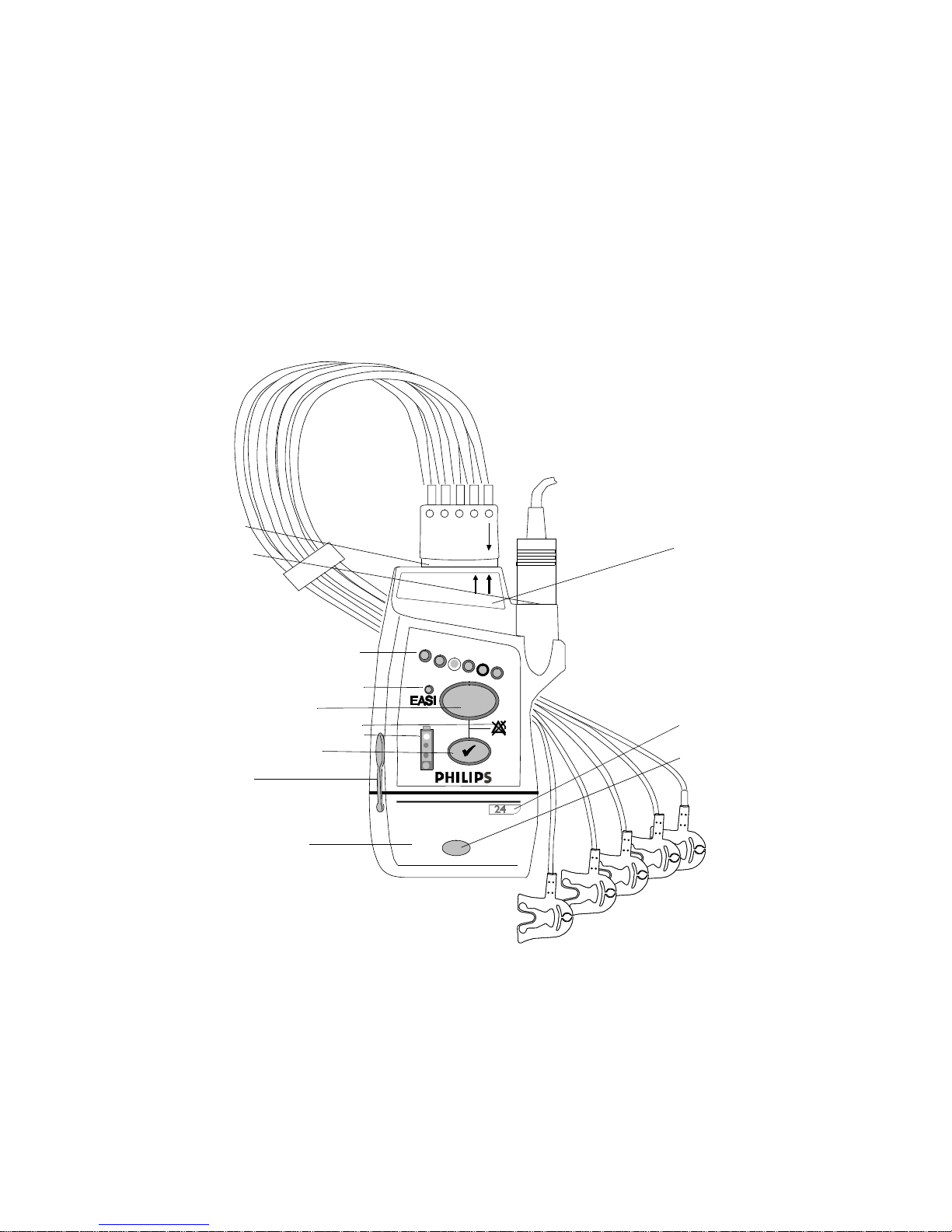
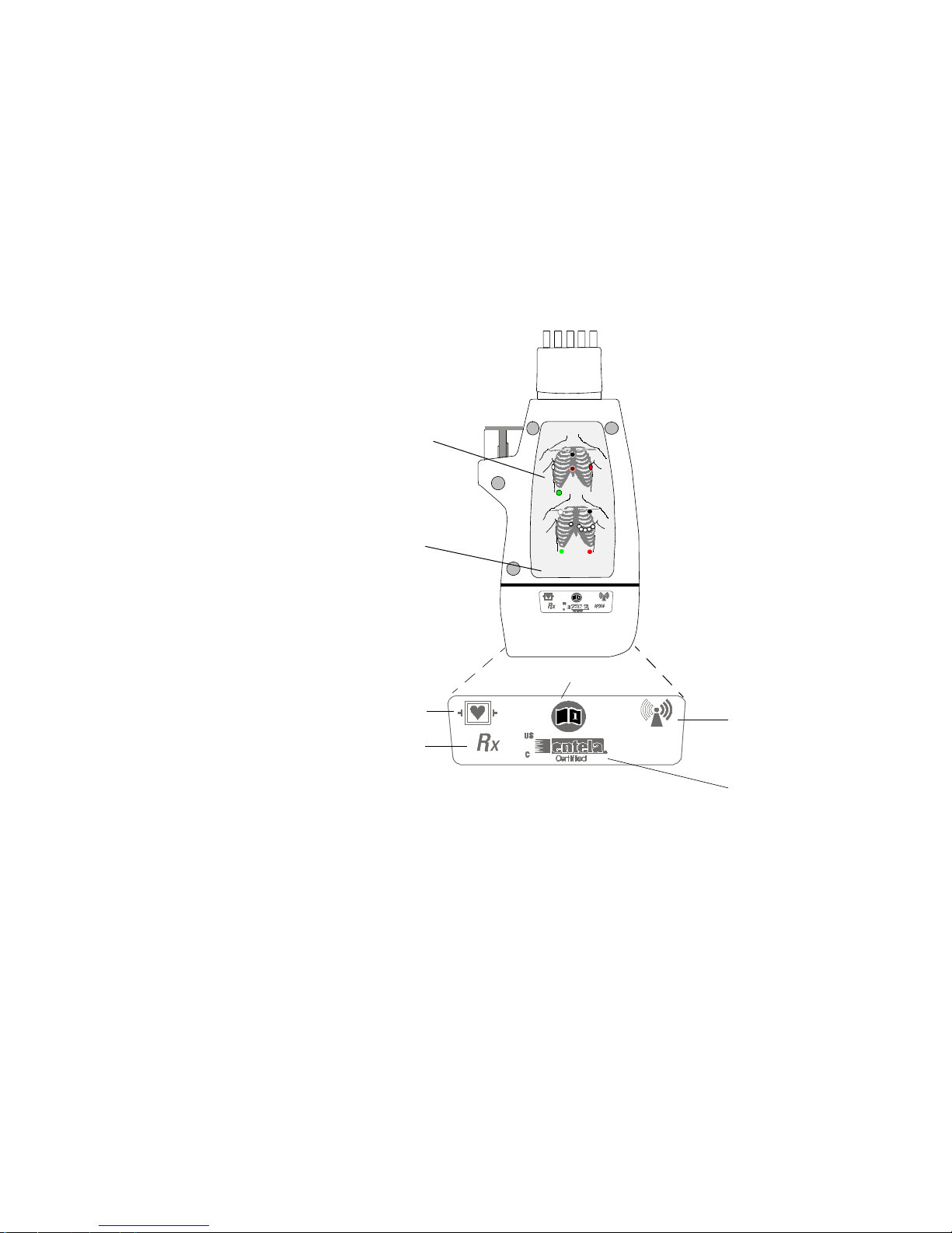
Transceiver Controls - Front
P1
The IntelliVue Transceiver
P2
+
IntelliVue T R x
M4841A
EASI, 3
5,6
I1
I2
B1
I3
I4
B2
P3
B3
The labeled items in the diagram include: Buttons (B1-B3);
Indicators (I1-I4); Labels (L1-L4); Ports (P1-P3). Additional
Labels, and Safety Symbols & Other Markings (S1-S12, appear on the back of the transceiver.
IntelliVue TRx+ Transceiver - Front View
L1
L2
L3
Basic Operation
1-7
The IntelliVue Transceiver
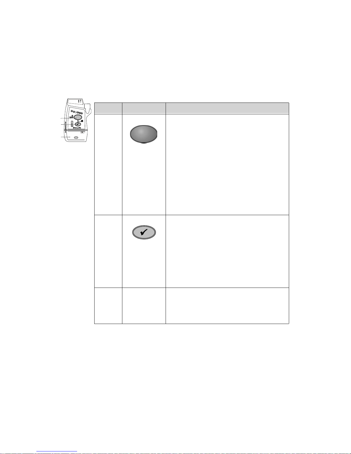
Buttons
+
IntelliVue TRx
M4841A
EASI, 3
5,6
Callout Button Definition
B1
B2
B3
B1 Telemetry Button: Depending on configuration,
B2 Check Button. Initiates a Status Check of the
directs the Information Center to generate a Nurse
Call alarm, remote recording, Nurse Call alarm
and recording, or none. See “Patient-Configurable
Settings in Telemetry Setup” on page 6-3.
Note—Delayed recordings generated by the
Telemetry button are stored in Alarm Review at
the Information Center.
When pressed simultaneously with the Check
button, turns Alarm Suspend/Pause on/off (not
when tethered to TeleMon). See “Suspending/
Pausing Alarms” on page 2-2.
Transceiver. See “Status Check” on page 1-18.
1-8 Basic Operation
When pressed simultaneously with the Telemetry
Button, turns Alarm Suspend/Pause on/off (not
when tethered to TeleMon). See “Suspending/
Pausing Alarms” on page 2-2.
Silences the Find Device tone.See “Telemetry
Controls in the Patient Window” on page 6-2.
B3 Power On/Off Battery Compartment. Insertion of batteries
turns transceiver power on; removal of batteries
turns power off. See “Turning the Transceiver
On” on page 1-15.

I1
I2
I3
I4
Indicators
+
IntelliVue TRx
M4841A
EASI, 3
5,6
The IntelliVue Transceiver
Callout Indicator Definition
I1 Lead Indicator.
Illuminates momentarily during leadset
insertion to indicate attached leads.
Illluminates when Check button is pressed to
indicate attached leads.
During a Leads Off condition, illuminates to
indicate the lead(s) that need to be reapplied.
Momentarily illuminates three alternate
lights, indicating the transceiver has no
Equipment Label assigned.
I2 EASI Indicator. Illuminates momentarily
upon insertion of leadset in EASI position.
EASI
Illuminates when Check button is pressed if
EASI is in use.
I3 Alarms Suspend/Pause Indicator.
Illuminates during 3 minute alarm pause
initiated at transceiver or Information Center.
I4 Battery Gauge. Illuminates when the EHck
button is pressed to indicate the amount of
power remaining in the batteries. Valid only
for recommended battery type. See
“Checking the Battery Power Level” on page
1-22.
Basic Operation
1-9
The IntelliVue Transceiver
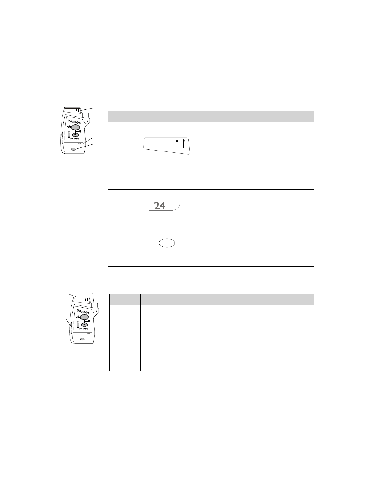
Labels
IntelliVue TRx
M4841A
+
EASI, 3
L1
5,6
Callout Label Definition
L2
L3
L1 Leadset Insertion Guide. Assist in aligning
IntelliVue TRx
M4841A
EASI, 3
the ECG cable for different leadsets. See
“Connecting the ECG Cable” on page 3-19.
5,6
Note—If your unit uses only one monitoring
configuration, the transceiver may have
special "lock out" plugs that allow only one
way to insert the leadset.
L2 Device Identification Label. Identifies the
device within the IntelliVue Wireless
Network.
L3 Unit Identification Label. Uses one of
seven color-coded labels to identify a clinical
unit.
Ports
IntelliVue TRx
M4841A
P2
+
EASI, 3
5,6
Callout Definition
Note— Ports can be covered with protective covers (gunk guards) when not in
P1
P3
use. See “Gunk Guards” on page -4.
1-10 Basic Operation
P1 ECG Leadset Port. Connection for 3-wire or 5-wire leadset.
P2 SpO
Sensor Port. Connection for SpO2 sensor. (IntelliVue TRx+
2
only)
P3 TeleMon/Service Port. Connection for cable to TeleMon
Companion Monitor or to Service Tool.
Transceiver Controls - Back
L4
S1
EASI
EASI
EASI
I
S
E
1
FCCID: XXXXXXXX
S6
The IntelliVue Transceiver
A
2
6
5
3
4
S7-S11 not shown
(inside battery
compartment)
S2
S3
IntelliVue TRx+ Transceiver - Back View
Basic Operation
S4
S5
1-11
The IntelliVue Transceiver
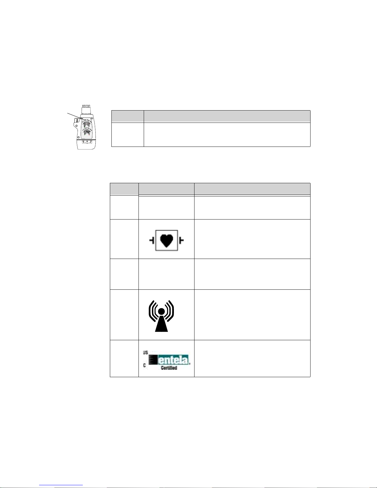
Labels
L4
EASI
EASI
I
Safety
Symbols &
Other Marks
S
A
E
1
2
6
345
Callout Definition
L4 Electrode Placement Diagrams (See “Positioning ECG
Electrodes” on page 3-8.)
Callout Label Definition
S1
FCCID: XXXXXXXX
Federal Communications Commission
(FCC) (PTT) label
S2 Patient connections are protected against
defibrillation (DEFIBRILLATIONPROOF) and are a TYPE CF APPLIED
PART.
S3 Prescription device.
R
x
1-12 Basic Operation
S4 Non-Ionizing Radiation. Interference to
electronic equipment may occur in the
vicinity of devices marked with this
symbol.
S5
Complies with all applicable Canadian and
American standards.
The IntelliVue Transceiver
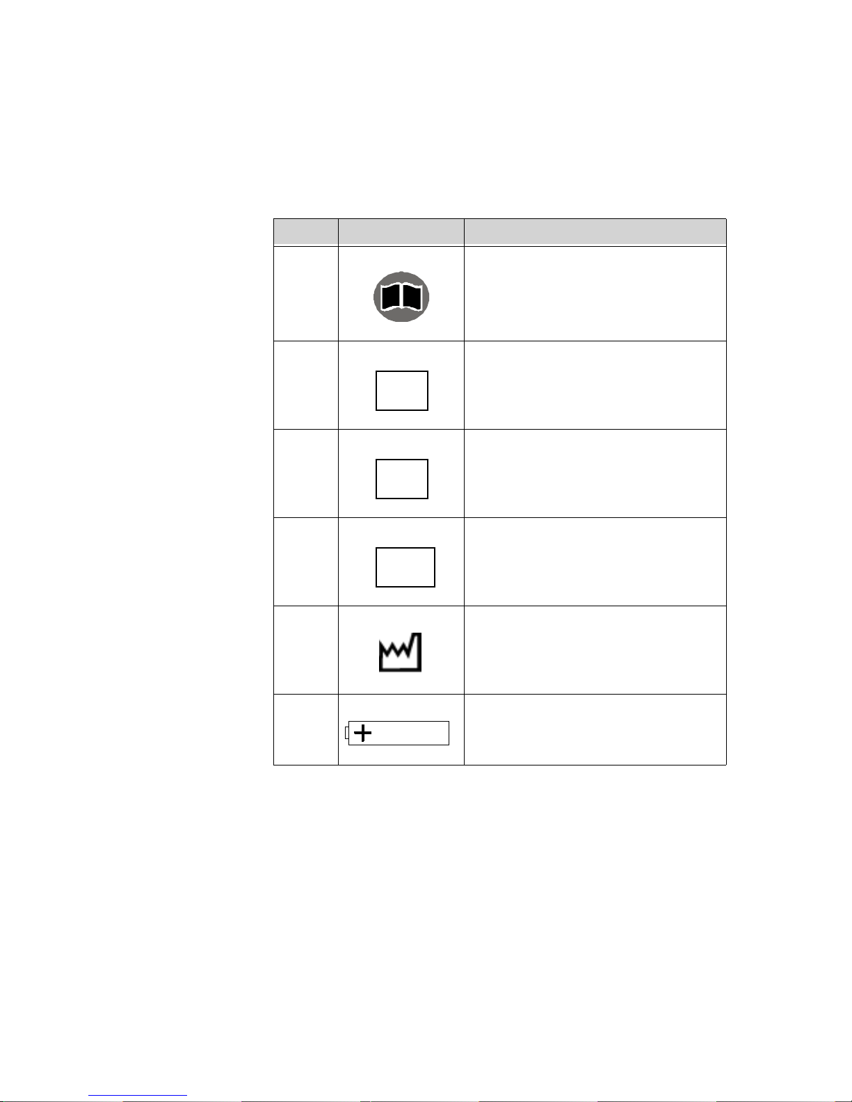
Callout Label Definition
S6 Follow operating instructions.
i
S7 Philips Catalog Number
REF
S8 Serial Number (inside battery
compartment). Needed to identify the
SN
S9 MAC Address of device
equipment during a call to the Response
Center.
MAC
Auditory
Information
Signals
S10 Date of manufacture
S11 Battery Polarity
The transceiver produces auditory feedback to inform you of measurement and
battery conditions. Adjustable sounds can be set to 5 different volume levels or
turned off per patient at the Information Center (see “Patient-Configurable
Settings in Telemetry Setup” on page 6-3). Adjustable sounds include Check
Basic Operation
1-13

The IntelliVue Transceiver
button Standby functions, SpO2 measurement complete, outside of coverage
area warning, and the pulse detection tone.
Auditory Information
Signal
Definition
Single Tone Self Test passed
SpO
Spot Check measurement successfulnoyes
2
Single Tone, low pitch Pulse detection successful (when locally
initiated)
Double Tone Self Test failed
SpO
Spot Check measurement failed
2
Double Tone repeated
Out of range yes
every 5 seconds
Continuous Double
Find Device no
Tone, two pitches
Single Tone (when
Check button pressed)
Double Tone (when
Check button pressed)
Transceiver is associated with sector at
Information Center (after Standby).
Transceiver not associated with sector at
Information Center (after Standby).
Volume/Mute
Adjustable
yes
no
yes
yes
yes
Double Tone and all
indicators flashing
Fast Double Tone and
alternate Leads Off
indicators flashing
1-14 Basic Operation
No equipment label is assigned from
Information Center. No monitoring.
Equipment label is received from
Information Center and is awaiting local
acknowledgment by Check button press.
no
no

Transceiver
Safety
Information
Turning the Transceiver On
WarningWarning
If another radio medical device is operating at the same frequency as an
IntelliVue Transceiver, it is possible that either device will not function
properly.
WarningWarning
Although the transceiver is shielded against Electromagnetic Interference
(EMI), avoid the use of other electrically radiating devices in close
proximity to the transceiver because they might interfere with transceiver
operation.
WarningWarning
Place the transceiver in a pouch or over clothing, or both, during patient
use. The transceiver should not touch the patient’s skin during use.
Turning the Transceiver On
WarningWarning
Arrhythmia relearning is initiated whenever the transceiver is powered
down for one minute or longer. Be sure to check your patient’s arrhythmia
annotation for accuracy whenever relearn has occurred.
The transceiver is powered by two AA alkaline batteries. To turn the transceiver
on, insert both batteries. Remove the batteries to turn the power off.
The configuration data set by the Service Provider prior to transceiver use is
retained after battery removal.
Basic Operation
1-15
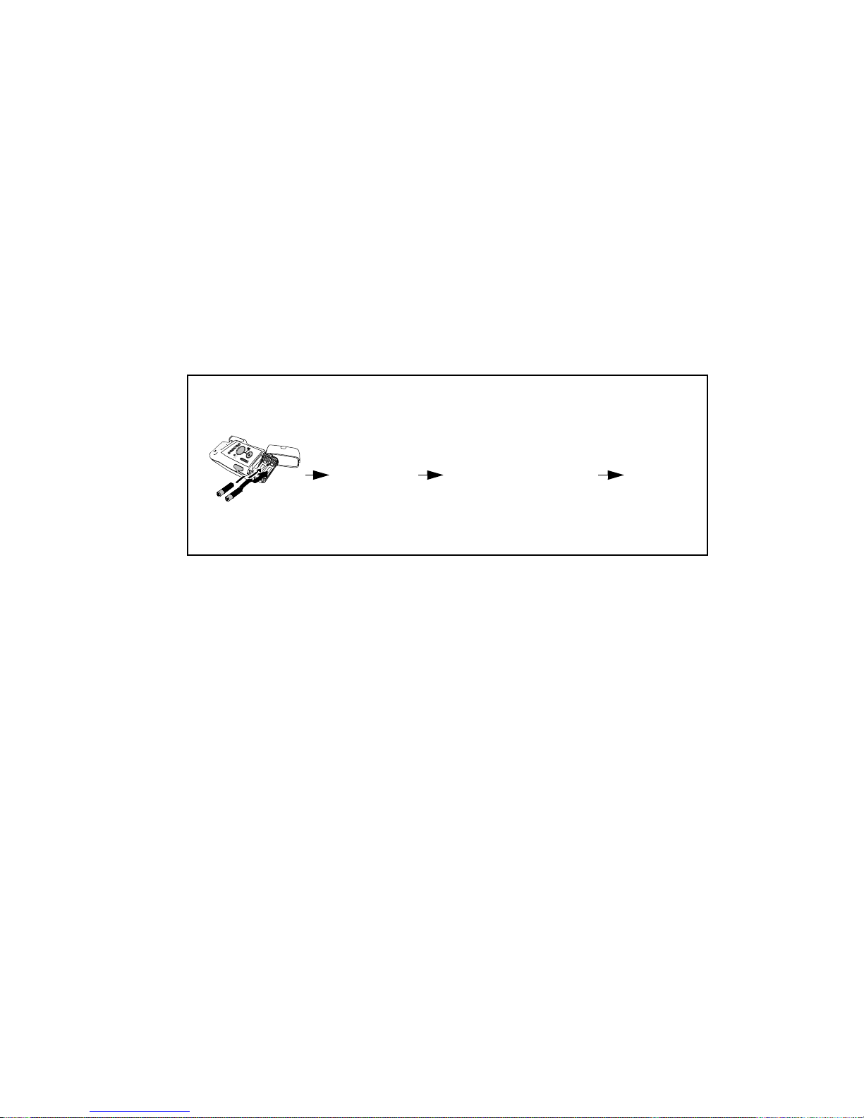
Turning the Transceiver On
When the transceiver is turned on, all indicators illuminate briefly and a
sequence of sounds indicates the instrument is ready for use. You should hear a
single beep indicating that the self test was passed, followed by a series of
double beeps while the transceiver attempts to associate with the Information
Center. The cessation of sounds indicates a successful association. If you hear a
single double beep or any other sound sequence, the automatic self-test of the
device has not passed, or there is another problem. Contact your Service
Provider.
Sounds at successful start-up
Self-test
insert batteries
Turning the
Transceiver
Off
Auto Shutoff Automatic Shutoff causes the transceiver to stop broadcasting a radio signal if
Turn off the transceiver by removing the batteries. A NO SIGNAL technical
alarm will be in effect at the Information Center until the device is turned on or
until Standby is initiated.
Telemetry monitoring can be turned off in the following ways:
• Manually, by activating Monitoring Standby at the Information Center
(see “Standby Mode” on page 2-5).
• Automatically, if Transceiver RF Auto Shutoff is enabled and there is no
ECG signal for 10 minutes.
Note—Turning off telemetry monitoring does not turn off the transceiver.
there is no ECG signal for 10 minutes. This prevents interference with other
transceivers in use. The technical alarm text at the Information Center is
Transmitter Off. To conserve battery power, remove batteries.
1 beep (pass)
Transceiver looking
for Info Center
beep beep repeated
every 3 seconds
Connected
no beep
1-16 Basic Operation
 Loading...