

Page 1
IntelliVue Telemetry System Infrastructure
Installation and Service Guide
Patient-worn Transceivers
1.4/2.4 GHz Access Points
ITS Synchronization Unit
ITS Power over Ethernet Unit
Access Point Controller
ICN Network Switch
Part Number: M3185-91934
Printed in the U.S.A.
June, 2007
Second Edition
*M3185-91934*
Page 2

Proprietary Information
This document contains proprietary information that is protected by copyright.
Copyright
Copyright © 2007 Koninklijke Philips Electronics N.V. All Rights Reserved.
Manufacturer
Philips Medical Systems
3000 Minuteman Road
Andover, MA 01810-1099
(978) 687-1501
This document was printed in the United States of America.
Trademark Acknowledgements
Symbol is a trademark of Symbol Technologies, Inc.
HP is a registered trademark of Hewlett-Packard Company
Cisco is a registered trademark of Cisco Systems
MS-SQL is a registered trademark of Microsoft Corporation
Nortel is a registered trademark of Nortel Networks Limited
3COM is a registered trademark of 3COM Corporation
Extreme is a registered trademark of Extreme Networks
All other trademarks, trade names and company names referenced herein are used for identification purposes only and are
the property of their respective owners.
Warranty
The information contained in this document is subject to change without notice. Philips Medical Systems makes no warranty
of any kind with regard to this material, including, but not limited to, the implied warranties or merchantability and fitness for
a particular purpose. Philips Medical Systems shall not be liable for errors contained herein or for incidental or
consequential damages in connection with the furnishing, performance, or use of this material.
Printing History
New editions of this document will incorporate all material updated since the previous edition. The documentation printing
date and part number indicate its current edition. The printing date and edition number change when a new edition is
printed. The document part number changes when extensive technical changes are incorporated.
Second Edition ...................................................................................................................................................................June, 2007
First Edition ................................................................................................................................................................. February, 2007
ii
Page 3

Contents
About This Guide
Chapter 1: Overview
Introduction . . . . . . . . . . . . . . . . . . . . . . . . . . . . . . . . . . . . . . . . . . . . . . . . . . . . . . . 1-2
IntelliVue Telemetry System Infrastructure Components . . . . . . . . . . . . . . . . . . . 1-3
ITS Smart-hopping Access Points . . . . . . . . . . . . . . . . . . . . . . . . . . . . . . . . . . 1-3
ITS Standard Access Points . . . . . . . . . . . . . . . . . . . . . . . . . . . . . . . . . . . . . 1-3
ITS Core Access Points . . . . . . . . . . . . . . . . . . . . . . . . . . . . . . . . . . . . . . . . . 1-6
Access Point Controller. . . . . . . . . . . . . . . . . . . . . . . . . . . . . . . . . . . . . . . . . . . 1-9
Front Panel LEDs. . . . . . . . . . . . . . . . . . . . . . . . . . . . . . . . . . . . . . . . . . . . . 1-10
Rear Panel Connectors and LEDs . . . . . . . . . . . . . . . . . . . . . . . . . . . . . . . 1-10
Synchronization Unit . . . . . . . . . . . . . . . . . . . . . . . . . . . . . . . . . . . . . . . . . . . . 1-11
Front-panel Connectors, Controls, and Indicators . . . . . . . . . . . . . . . . . . 1-11
Rear-panel Connectors . . . . . . . . . . . . . . . . . . . . . . . . . . . . . . . . . . . . . . . . 1-12
Power over Ethernet Unit . . . . . . . . . . . . . . . . . . . . . . . . . . . . . . . . . . . . . . . . 1-12
Uninterruptible Power Supply. . . . . . . . . . . . . . . . . . . . . . . . . . . . . . . . . . . . . 1-12
General Intellivue Telemetry System Data Flow . . . . . . . . . . . . . . . . . . . . . . . . . 1-13
Defined ITS Bandwidth . . . . . . . . . . . . . . . . . . . . . . . . . . . . . . . . . . . . . . . . . . . . . 1-14
1.4 GHz ITS Bandwidth. . . . . . . . . . . . . . . . . . . . . . . . . . . . . . . . . . . . . . . . . . 1-14
Standard WMTS Channels . . . . . . . . . . . . . . . . . . . . . . . . . . . . . . . . . . . . . 1-14
Carved-out Areas. . . . . . . . . . . . . . . . . . . . . . . . . . . . . . . . . . . . . . . . . . . . . 1-14
Required FCC Registration . . . . . . . . . . . . . . . . . . . . . . . . . . . . . . . . . . . . . 1-15
2.4 GHz ITS Bandwidth. . . . . . . . . . . . . . . . . . . . . . . . . . . . . . . . . . . . . . . . . . 1-15
Supported Topologies and System Limits . . . . . . . . . . . . . . . . . . . . . . . . . . . . . . 1-18
Installing the ITS within a Non-routed ICN. . . . . . . . . . . . . . . . . . . . . . . . . . . 1-18
Installing the ITS on a Routed ICN Topology . . . . . . . . . . . . . . . . . . . . . . . . . 1-21
System Limits . . . . . . . . . . . . . . . . . . . . . . . . . . . . . . . . . . . . . . . . . . . . . . . . . 1-24
IntelliVue Telemetry System Specifications. . . . . . . . . . . . . . . . . . . . . . . . . . . . . 1-24
Power Requirements . . . . . . . . . . . . . . . . . . . . . . . . . . . . . . . . . . . . . . . . . . . 1-24
Radio Compliance Specifications . . . . . . . . . . . . . . . . . . . . . . . . . . . . . . . . . 1-26
Safety Regulatory Compliance . . . . . . . . . . . . . . . . . . . . . . . . . . . . . . . . . . . . 1-26
Environmental Specifications. . . . . . . . . . . . . . . . . . . . . . . . . . . . . . . . . . . . . 1-27
IntelliVue Telemetry System Infrastructure Product Numbers. . . . . . . . . . . . . . 1-28
Chapter 2: Planning Your ITS Deployment
Respecting Patient Care Boundaries . . . . . . . . . . . . . . . . . . . . . . . . . . . . . . . . . . . 2-2
General ITS Infrastructure Site Planning Guidelines. . . . . . . . . . . . . . . . . . . . . . . 2-3
Performing a Physical Space Assessment. . . . . . . . . . . . . . . . . . . . . . . . . . . . . . . 2-4
IntelliVue Telemetry System Infrastructure Installation and Service Guide iii
Page 4

Contents
Understanding the Radius of Coverage (RoC) Metric. . . . . . . . . . . . . . . . . . . 2-4
Determining the Number of Patient-worn Transceivers to be Supported. . . 2-5
Determining AP Installation Locations. . . . . . . . . . . . . . . . . . . . . . . . . . . . . . . 2-6
Symmetrical Patient Room Layout. . . . . . . . . . . . . . . . . . . . . . . . . . . . . . . . 2-6
Asymmetrical Patient Room Layout. . . . . . . . . . . . . . . . . . . . . . . . . . . . . . . 2-7
Placing RoC Cells on a Floorplan . . . . . . . . . . . . . . . . . . . . . . . . . . . . . . . . . 2-7
Core AP Placements . . . . . . . . . . . . . . . . . . . . . . . . . . . . . . . . . . . . . . . . . . . 2-8
Access Point Placement Guidelines. . . . . . . . . . . . . . . . . . . . . . . . . . . . . . 2-10
Determining the Required Number of APCs . . . . . . . . . . . . . . . . . . . . . . . . . 2-11
Locating Equipment Closets. . . . . . . . . . . . . . . . . . . . . . . . . . . . . . . . . . . . . . 2-11
Planning Cable Runs. . . . . . . . . . . . . . . . . . . . . . . . . . . . . . . . . . . . . . . . . . . . 2-12
Defining the UPS Deployment . . . . . . . . . . . . . . . . . . . . . . . . . . . . . . . . . . . . 2-13
Planning the Sync Network Layout. . . . . . . . . . . . . . . . . . . . . . . . . . . . . . . . . . . . 2-14
Daisy-chained Topology . . . . . . . . . . . . . . . . . . . . . . . . . . . . . . . . . . . . . . . . . 2-15
Star Topology Sync Network. . . . . . . . . . . . . . . . . . . . . . . . . . . . . . . . . . . . . . 2-16
Hybrid Sync Network Topology. . . . . . . . . . . . . . . . . . . . . . . . . . . . . . . . . . . . 2-17
Planning Your AP Groupings . . . . . . . . . . . . . . . . . . . . . . . . . . . . . . . . . . . . . . . . . 2-17
Configuration Groups in the Config Wizard (IIC) . . . . . . . . . . . . . . . . . . . . . . 2-17
Configuration Groups in the IntelliVue Telemetry System . . . . . . . . . . . . . . 2-17
Performing an RF Assessment . . . . . . . . . . . . . . . . . . . . . . . . . . . . . . . . . . . . . . . 2-19
Understanding RF Coexistence Issues in the 2.4 GHz Spectrum . . . . . . . . 2-19
Transient Noise in the 2.4 GHz Spectrum. . . . . . . . . . . . . . . . . . . . . . . . . . . 2-19
Microwave Ovens . . . . . . . . . . . . . . . . . . . . . . . . . . . . . . . . . . . . . . . . . . . . 2-19
Bluetooth Devices . . . . . . . . . . . . . . . . . . . . . . . . . . . . . . . . . . . . . . . . . . . . 2-20
Other Transient Devices . . . . . . . . . . . . . . . . . . . . . . . . . . . . . . . . . . . . . . . 2-20
Continuous Noise in the 2.4 GHz Spectrum . . . . . . . . . . . . . . . . . . . . . . . . . 2-20
802.11/WiFi Devices . . . . . . . . . . . . . . . . . . . . . . . . . . . . . . . . . . . . . . . . . 2-20
Cordless Phones and Headsets . . . . . . . . . . . . . . . . . . . . . . . . . . . . . . . . . 2-21
Wireless Security Devices. . . . . . . . . . . . . . . . . . . . . . . . . . . . . . . . . . . . . . 2-21
ZigBee Devices . . . . . . . . . . . . . . . . . . . . . . . . . . . . . . . . . . . . . . . . . . . . . . 2-21
RF Site Survey Guidelines . . . . . . . . . . . . . . . . . . . . . . . . . . . . . . . . . . . . . . . 2-22
Survey Objectives . . . . . . . . . . . . . . . . . . . . . . . . . . . . . . . . . . . . . . . . . . . . 2-22
Using the Spectrum Analyzer Tool . . . . . . . . . . . . . . . . . . . . . . . . . . . . . . . 2-22
Determining Measurement Locations . . . . . . . . . . . . . . . . . . . . . . . . . . . . 2-22
Assigning 2.4 GHz ITS Channels. . . . . . . . . . . . . . . . . . . . . . . . . . . . . . . . . . . . . . 2-23
Avoiding WiFi Interference . . . . . . . . . . . . . . . . . . . . . . . . . . . . . . . . . . . . . . . 2-23
2.4 GHz ITS Frequency Plans . . . . . . . . . . . . . . . . . . . . . . . . . . . . . . . . . . . . . 2-24
Frequency Plan 1,6,11 . . . . . . . . . . . . . . . . . . . . . . . . . . . . . . . . . . . . . . . . 2-24
Frequency Plan 1,7,13 . . . . . . . . . . . . . . . . . . . . . . . . . . . . . . . . . . . . . . . . 2-24
Using “Advanced” 2.4 GHz ITS Channel Configurations . . . . . . . . . . . . . . . 2-24
Completing ITS Installation Worksheets . . . . . . . . . . . . . . . . . . . . . . . . . . . . . . . 2-25
ITS Infrastructure Equipment Summary Table . . . . . . . . . . . . . . . . . . . . . . . 2-26
ITS Access Point Equipment Summary Table . . . . . . . . . . . . . . . . . . . . . . . . 2-26
iv
Page 5

Contents
APC Configuration Worksheet . . . . . . . . . . . . . . . . . . . . . . . . . . . . . . . . . . . . 2-29
Setting Descriptions . . . . . . . . . . . . . . . . . . . . . . . . . . . . . . . . . . . . . . . . . . 2-29
1.4 GHz Default AP Configuration Worksheet. . . . . . . . . . . . . . . . . . . . . . . . 2-32
Setting Descriptions . . . . . . . . . . . . . . . . . . . . . . . . . . . . . . . . . . . . . . . . . . 2-32
Blank Template . . . . . . . . . . . . . . . . . . . . . . . . . . . . . . . . . . . . . . . . . . . . . . 2-32
2.4 GHz Default AP Configuration Worksheet. . . . . . . . . . . . . . . . . . . . . . . . 2-33
Setting Descriptions . . . . . . . . . . . . . . . . . . . . . . . . . . . . . . . . . . . . . . . . . . 2-33
Blank Template . . . . . . . . . . . . . . . . . . . . . . . . . . . . . . . . . . . . . . . . . . . . . . 2-34
AP Group Configuration Worksheet . . . . . . . . . . . . . . . . . . . . . . . . . . . . . . . . 2-35
Setting Descriptions . . . . . . . . . . . . . . . . . . . . . . . . . . . . . . . . . . . . . . . . . . 2-35
Blank Template . . . . . . . . . . . . . . . . . . . . . . . . . . . . . . . . . . . . . . . . . . . . . . 2-35
Chapter 3: Installing and Configuring the ITS
High-level ITS Installation and Configuration Procedure . . . . . . . . . . . . . . . . . . . 3-2
Step 1. Complete the ITS Installation Worksheets.. . . . . . . . . . . . . . . . . . . . . . . . 3-4
Step 2. Install the ITS Infrastructure Components.. . . . . . . . . . . . . . . . . . . . . . . . 3-4
Step 3. Set Up Your Service PC. . . . . . . . . . . . . . . . . . . . . . . . . . . . . . . . . . . . . . . . 3-7
Configuring Your PC to Connect to the ITS Wireless Subnet . . . . . . . . . . . . . 3-7
Copying the Upgrade Wizard files to your PC . . . . . . . . . . . . . . . . . . . . . . . . . 3-9
Step 4. Perform Initial Configuration of the APCs to be Installed. . . . . . . . . . . . 3-12
Step 5. Add the APCs to the Network. . . . . . . . . . . . . . . . . . . . . . . . . . . . . . . . . . 3-14
Step 6. Run the Philips Upgrade Wizard.. . . . . . . . . . . . . . . . . . . . . . . . . . . . . . . 3-16
Compatibility . . . . . . . . . . . . . . . . . . . . . . . . . . . . . . . . . . . . . . . . . . . . . . . . . . 3-16
Using the Upgrade Wizard . . . . . . . . . . . . . . . . . . . . . . . . . . . . . . . . . . . . . . . 3-17
Step 7. Verify and Configure Important ITS Settings via the APC Interface. . . . 3-21
Verifying the Filter Settings. . . . . . . . . . . . . . . . . . . . . . . . . . . . . . . . . . . . . . . 3-21
Verifying the BOOTP/DHCP Settings . . . . . . . . . . . . . . . . . . . . . . . . . . . . . . . 3-23
Configuring the Access Point Default Settings . . . . . . . . . . . . . . . . . . . . . . . 3-25
Configuring the 1.4 GHz Access Point Default Settings . . . . . . . . . . . . . . 3-25
Configuring the 2.4 GHz Access Point Default Settings . . . . . . . . . . . . . . 3-26
Configuring AP Groups . . . . . . . . . . . . . . . . . . . . . . . . . . . . . . . . . . . . . . . . . . 3-28
Step 8. Run the Philips Upgrade Wizard Again.. . . . . . . . . . . . . . . . . . . . . . . . . . 3-33
Step 9. Add APs to the Network.. . . . . . . . . . . . . . . . . . . . . . . . . . . . . . . . . . . . . . 3-37
Step 10. Rename Installed APs and Remote Antennas. . . . . . . . . . . . . . . . . . . 3-40
Step 11. Run the Philips Upgrade Wizard Again. . . . . . . . . . . . . . . . . . . . . . . . . 3-41
Step 12. Export the ITS Configuration to a Disk File. . . . . . . . . . . . . . . . . . . . . . 3-49
Step 13. Restore your Service PC to its Original Settings. . . . . . . . . . . . . . . . . . 3-49
Step 14. Install ITS Bedside Monitors and Patient-worn Transceivers.. . . . . . . 3-50
IntelliVue Telemetry System Infrastructure Installation and Service Guide v
Page 6

Contents
Chapter 4: Expanding or Modifying an Installed ITS
Expanding an Installed IntelliVue Telemetry System . . . . . . . . . . . . . . . . . . . . . . 4-2
General ITS Expansion Guidelines . . . . . . . . . . . . . . . . . . . . . . . . . . . . . . . . . . . . . 4-4
APC Upgrade/Expansion Guidelines . . . . . . . . . . . . . . . . . . . . . . . . . . . . . . . . . . . 4-5
Adding APs to an Installed ITS . . . . . . . . . . . . . . . . . . . . . . . . . . . . . . . . . . . . . . . . 4-6
Adding an AP via Auto-Registration . . . . . . . . . . . . . . . . . . . . . . . . . . . . . . . . . 4-7
Adding an AP via Manual MAC Address Input. . . . . . . . . . . . . . . . . . . . . . . . 4-10
Renaming Newly Installed APs and Remote Antennas . . . . . . . . . . . . . . . . 4-12
Adding APCs to an Existing ITS . . . . . . . . . . . . . . . . . . . . . . . . . . . . . . . . . . . . . . . 4-13
Adding New AP Groups to an Existing ITS Configuration . . . . . . . . . . . . . . . . . . 4-15
Add the New AP Groups . . . . . . . . . . . . . . . . . . . . . . . . . . . . . . . . . . . . . . . 4-15
Configure the New AP Groups . . . . . . . . . . . . . . . . . . . . . . . . . . . . . . . . . . 4-16
Replacing an AP, Remote Antenna, or APC in an Existing System. . . . . . . . . . . 4-17
Replacing an ITS Access Point . . . . . . . . . . . . . . . . . . . . . . . . . . . . . . . . . . . . 4-18
Replacing a Remote Antenna. . . . . . . . . . . . . . . . . . . . . . . . . . . . . . . . . . . . . 4-18
Replacing an ITS APC . . . . . . . . . . . . . . . . . . . . . . . . . . . . . . . . . . . . . . . . . . . 4-19
Replacing a Master APC . . . . . . . . . . . . . . . . . . . . . . . . . . . . . . . . . . . . . . . 4-19
Replacing a Slave APC . . . . . . . . . . . . . . . . . . . . . . . . . . . . . . . . . . . . . . . . 4-20
Chapter 5: Troubleshooting and Testing
ITS Access Point Test and Inspection Procedures . . . . . . . . . . . . . . . . . . . . . . . . 5-2
ITS Access Point Controller Test and Inspection Procedures. . . . . . . . . . . . . . . . 5-3
ITS Sync Unit Test and Inspection Procedures . . . . . . . . . . . . . . . . . . . . . . . . . . . 5-4
ITS Power over Ethernet Unit Test and Inspection Procedures . . . . . . . . . . . . . . 5-5
ITS Uninterruptible Power Supply Test and Inspection Procedures. . . . . . . . . . . 5-6
ITS Network Switch Test and Inspection Procedures . . . . . . . . . . . . . . . . . . . . . . 5-7
Troubleshooting Known Issues. . . . . . . . . . . . . . . . . . . . . . . . . . . . . . . . . . . . . . . . 5-8
Importing ITS Configuration Files . . . . . . . . . . . . . . . . . . . . . . . . . . . . . . . . . . . . . 5-10
Appendix A: Installing Multiple ITSs at a Single Hospital Site
General Requirements for Installing Multiple ITSs at a Site. . . . . . . . . . . . . . . . . A-2
Transceiver Installation Requirements for Multiple ITSs . . . . . . . . . . . . . . . . . . . A-3
Patient-worn Transceivers . . . . . . . . . . . . . . . . . . . . . . . . . . . . . . . . . . . . . . . . A-3
Extra MAC addresses in the Label Assignment Screen . . . . . . . . . . . . . . . . . A-3
Sync Network Requirements for Multiple ITSs . . . . . . . . . . . . . . . . . . . . . . . . . . . A-4
vi
Page 7

Contents
Appendix B: Routed Topology Configuration Information
ICN and ITS Subnet Device IP Addresses . . . . . . . . . . . . . . . . . . . . . . . . . . . . . . . B-2
Sample Routed Topology . . . . . . . . . . . . . . . . . . . . . . . . . . . . . . . . . . . . . . . . . . . . B-3
Index
IntelliVue Telemetry System Infrastructure Installation and Service Guide vii
Page 8

Contents
viii
Page 9

About This Guide
This IntelliVue Telemetry System Infrastructure Installation and Service
Guide provides complete instructions and procedures for installing,
configuring, and servicing Philips 1.4/2.4 GHz IntelliVue Telemetry System
infrastructure devices. This section describes the document and includes:
• Audience
•Document Organization
• Notational Conventions
• Related Documentation
•Terminology
IntelliVue Telemetry System Infrastructure Installation and Service Guide ix
Page 10

About This Guide
Audience
The IntelliVue Telemetry System Infrastructure Installation and Service
Guide is written for qualified service personnel who will install, configure,
and service the 1.4 or 2.4 GHz IntelliVue Telemetry System infrastructure
as part of an overall IntelliVue Clinical Network (ICN) deployment.
Document Organization
The information in this guide is organized and presented as follows:
• Chapter 1, Overview, describes the IntelliVue Telemetry System and
• Chapter 2, Planning Your ITS Deployment, provides information and
• Chapter 3, Installing and Configuring the ITS, gives complete
how it is used to provide a bi-directional data flow between the
IntelliVue Information Center and patient-worn transceivers and
wireless bedside monitors.
procedures that must be followed to ensure a successful IntelliVue
Telemetry System deployment.
procedures to physically install the IntelliVue Telemetry System
components and configure the ITS Access Point Controllers and
Access Points.
• Chapter 4, Expanding or Modifying an Installed ITS, lists procedures to
expand or modify an existing, installed IntelliVue Telemetry System.
• Chapter 5, Troubleshooting and Testing, includes procedures to
troubleshoot and test an IntelliVue Telemetry System installation.
• Appendix A, Installing Multiple ITSs a Single Hospital Site, lists
configuration rules and guidelines to enable you to install up to 22
totally independent IntelliVue Telemetry Systems at a given
installation site.
• Appendix B, Routed Topology Configuration Information, provides
important information to help you configure a routed ITS topology.
x
Page 11

Notational Conventions
This guide uses the following notational conventions to convey
information:
About This Guide
Note
Caution Cautionary statements call attention to a condition that could result in loss
Warning
Notes call attention to important information.
of data or damage to equipment.
Warnings call attention to a condition that could result in physical injury.
Related Documentation
Please refer to these other documents for additional installation service
information about the IntelliVue Telemetry System and IntelliVue Clinical
Network:
• IntelliVue Clinical Network Installation and Service Guide
• IntelliVue Clinical Network Installation Guidelines and Topologies
(M1385-91928)
(M1385-91931)
• Cisco 2950 Switch Device Installation and Service Manual
(M1385-91914)
• HP2524 Switch Device Installation and Service Manual
(M1385-91919)
• Philips Access Point Controller Installation and Service Manual
(M3171-91901)
• 1.4 GHz IntelliVue Telemetry System Access Point Installation Guide
(M4842-91003)
• 2.4 GHz IntelliVue Telemetry System Access Point Installation Guide
(M4852-91901)
• Upgrading IntelliVue Telemetry System Access Point Controllers and
Access Points (M3185-91902)
• Philips Sync Unit Installation and Service Manual
(M4844-90025)
• ITS Transceiver Installation and Service Manual
(M4841-90060)
IntelliVue Telemetry System Infrastructure Installation and Service Guide xi
Page 12

About This Guide
Terminology
Please note the following terms, acronyms, and abbreviations used
throughout this document:
• IntelliVue Clinical Network (ICN) - This term refers to the entire Philips
network. In a routed topology, the ICN includes the routers and all
inter-connected Database Domain(s) and the IntelliVue Telemetry
System wireless subnet.
• Database Domain (DBS) - This term is used to describe the “network”
that contains the Standalone IntelliVue Information Center, or the
IntelliVue Database Server and its connected Information Centers,
Clients, bedsides, and infrastructure. This term applies to both routed
and non-routed topologies.
• IntelliVue Telemetry System (ITS) - Cellular wireless architecture that
provides two-way communications between patient-worn transceivers,
wireless bedside patient monitors, and the IntelliVue Information
Center.
• IntelliVue Wireless Subnet - This term is used to describe the IntelliVue
Telemetry System (ITS) “network” that contains the infrastructure
used in a routed topology to connect the IntelliVue Telemetry System
devices.
• Access Point (AP) - A network device that provides bi-directional
wireless access to the monitoring network for patient-worn
transceivers and wireless bedside monitors.
• Access Point Controller (APC) - A network device used to manage the
operation of the Access Points. One APC is elected the Master APC.
The Master APC supports the web interface to the system and
manages the master configuration.
• Access Point Group/AP Group - A logical grouping of APs. AP members
of the same AP Group will inherit common configuration settings
(defaults). AP groups will often map logically to the clinical units in
which the ITS is being installed.
• Partnered APC - Configurable element within an AP Group used to
determine which APC will manage the operation of the AP members of
a particular AP Group.
• RF Access Code - Configurable element in the Smart-hopping AP
defaults shared among APs and patient-worn transceivers to control
wireless access to the monitoring network. Portable devices will only
connect to access points with which they share access codes. The RF
Access Code allows a specific wireless client that is programmed with
a matching Access Point RF Access Code to connect to that Access
Point.
xii
Page 13

About This Guide
• Synchronization Unit - The Philips Sync Unit provides a necessary
common clock signal to synchronize all the IntelliVue Access Points in
the system. As patients ambulate around the hospital coverage area
their transmitted data are handed over from one AP to another
seamlessly without interruption or data loss.
• System ID - Configurable element in the APC Configuration to logically
associate Access Points and Access Point Controllers operating within
the same ITS.
IntelliVue Telemetry System Infrastructure Installation and Service Guide xiii
Page 14

About This Guide
xiv
Page 15

1
Overview
This chapter provides a high-level overview of the Philips IntelliVue
Telemetry System and includes:
• Introduction
• IntelliVue Telemetry System Infrastructure Components
• General Intellivue Telemetry System Data Flow
• Supported Topologies and System Limits
• IntelliVue Telemetry System Specifications
• IntelliVue Telemetry System Infrastructure Product Numbers
IntelliVue Telemetry System Infrastructure Installation and Service Guide 1-1
Page 16
Chapter 1: Overview
Introduction
The Philips IntelliVue Telemetry System (ITS) uses a cellular wireless architecture to
provide two-way communications between patient-worn transceivers and wireless
bedside patient monitors, and the IntelliVue Information Center.
Using the “Smart-hopping” wireless protocol based on Digital Enhanced Cordless
Telecommunications (DECT), the ITS provides monitoring capabilities for ambulatory
patients within a wide coverage area. The ITS transceivers (portable patient-worn
devices), wireless bedside monitors, and infrastructure operate on the 1.4 GHz US
Wireless Medical Telemetry Service (WMTS) band or on the 2.4 GHz band for
deployments outside of the USA.
The pocket-size transceiver sends patient data, and sends and receives control and
device information to and from the IntelliVue Information Center (bi-directional
communication) for subsequent monitoring, display, analysis, alarm detection,
operator alerts, data storage and permanent recording. Displays, settings,
recordings, and alarms are controlled from the IntelliVue Information Center.
Recordings can also be initiated from the patient worn-transceivers.
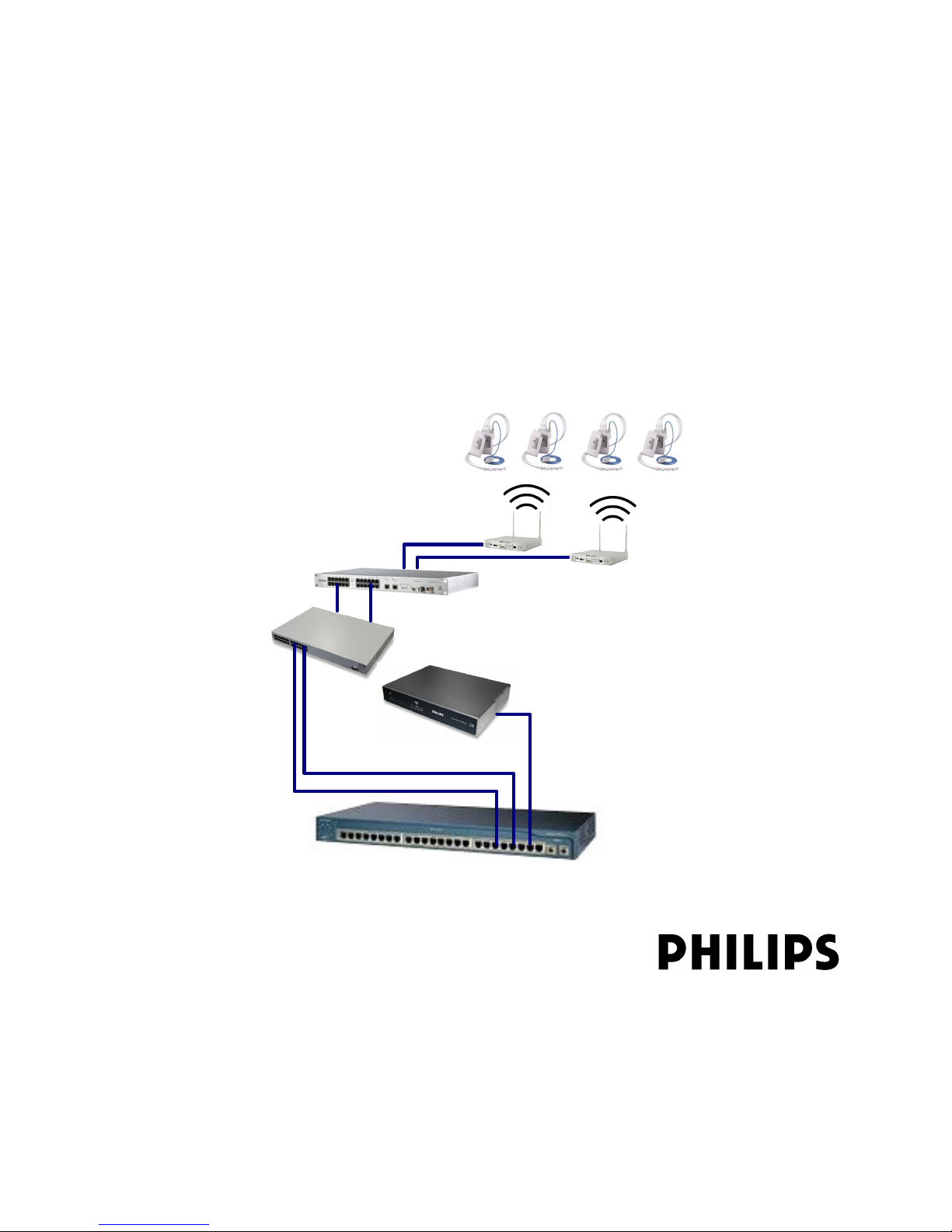
ICN Network Switch
Access Point Controller
1.4 GHz or 2.4 GHz
Smart-hopping
Access Points
Access Point Controller
Power over Ethernet Unit
Synchronization Unit
1.4 GHz
Remote Antenna
1.4 GHz
Core Access Point
1-2
1.4 GHz or 2.4 GHz
Patient-worn Transceivers and
Wireless Bedside Monitors
Figure 1-1: IntelliVue Telemetry System
Page 17

IntelliVue Telemetry System Infrastructure Components
You can configure the Access Point Controller to communicate with IntelliVue 1.4 or
2.4 GHz Smart-hopping Access Points (APs). IntelliVue 1.4 GHz APs can only
communicate with 1.4 GHz transceivers and monitors. Likewise, 2.4 GHz APs can
only communicate with 2.4 GHz transceivers and monitors. You cannot mix 1.4 GHz
and 2.4 GHz transceivers or monitors at a given ITS installation site.
Philips Smart-hopping technology dodges interference and locates the strongest
available signal wherever the patient roams. Dynamic wireless channel allocation
ensures best use of available wireless spectrum. When configured to operate in the
2.4 Ghz spectrum, the ITS is designed to co-exist with most 802.11 wireless
systems.
IntelliVue Telemetry System Infrastructure Components
The ITS infrastructure consists of an Ethernet LAN that can include LAN switches
and routers, and is used to interconnect multiple IntelliVue Access Points to one or
more Philips Access Point Controllers (APC).
The key function of the ITS infrastructure is to transport data from the transceivers
and wireless bedside monitors over a common wireless LAN-based infrastructure
(part of the IntelliVue Clinical Network) to/from the IntelliVue Information Center
where the data can be recorded or used to alert clinical operators as to a change in
monitored parameters.
ITS Standard
Access Points
Five major components comprise the Philips IntelliVue Telemetry System
infrastructure:
• 1.4 GHz or 2.4 GHz IntelliVue Telemetry System Smart-hopping Access Points
• Access Point Controller
•Synchronization Unit
• Power over Ethernet Unit
• Uninterruptible Power Supply
ITS Smart-hopping Access Points
The IntelliVue Telemetry System supports two types of Smart-hopping Access
Points:
• Standard Access Points (Model M4842A for 1.4 GHz and
Model ITS4852A for 2.4 GHz ITS)
• Core Access Points (Model ITS4843A for 1.4 GHz ITS only)
The IntelliVue Telemetry System Standard Smart-hopping Access Points (APs)
(Figure 1-2) provide an air-link to transmit and receive data between patient-worn
transceivers and the Philips IntelliVue Information Center via the ITS infrastructure.
The effective range of each Standard AP is typically 32 feet (9.8 m), and each
Standard AP supports up to 18 wireless clients (i.e., patient-worn transceivers or
bedside monitors). When monitored patients are ambulatory, patient data is
handled seamlessly between the other IntelliVue Access Points in the system. The
Standard AP is normally used with two antennas attached to it. Standard APs can be
mounted out of the way on corridor walls, or above or below ceiling tiles.
IntelliVue Telemetry System Infrastructure Installation and Service Guide 1-3
Page 18
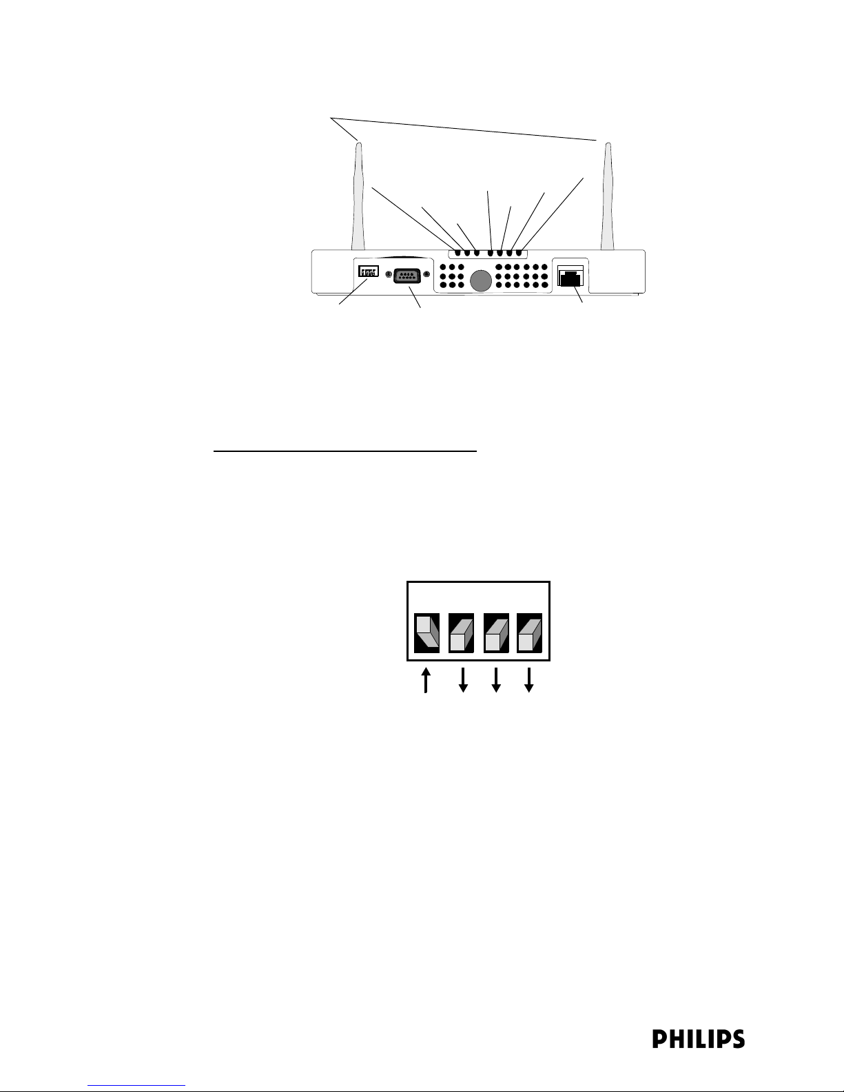
Chapter 1: Overview
Antennas
Power/Sync
Network
Status LEDs
ACT
Link
Radio
FDX
100M
Ethernet DIP Switches
Figure 1-2: IntelliVue Telemetry System Standard Access Point
Serial Port (Not Used)
100 Base-T Ethernet Interface
with RJ-45 Connector
Philips provides Standard ITS Access Points for the 1.4 GHz US Wireless Medical
Telemetry Service (WMTS) band (P/N 862113) and the 2.4 GHz band for
deployments outside of the US (P/N 862232).
ITS Standard AP Controls and Connectors
Note the following controls and connectors on the ITS Standard Smart-hopping AP:
• Ethernet Dual Inline Package (DIP) Switches - These four switches that are
accessible from the outside of the AP case are used to enable manual selection
of Ethernet link options. The switch settings should always be set as indicated
in Figure 1-3.
1 2 3 4
• Serial Port - The serial port is used only for manufacturing purposes.
• Ethernet Interface - The AP provides a 100 Base-T Ethernet interface with an
RJ-45 connector to connect the AP to the ITS Sync Unit.
The AP Ethernet interface provides data communications to and from the
IntelliVue Information Center over the ITS LAN infrastructure. It also presents
the 48Vdc power and synchronization signals required by the AP. The
synchronization signal is superimposed on the power supply voltage. You must
attach a ferrite block to the CAT 5 cabling (from the Sync Unit) no more than 20
inches (50 cm) from the RJ-45 connector to reduce electromagnetic (radiation)
interference. Table 1-1 lists the pin signals for the AP Ethernet interface.
1-4
Figure 1-3: Required AP DIP Switch Settings
Page 19

IntelliVue Telemetry System Infrastructure Components
Table 1-1: AP Ethernet Interface Pin Signals
Pin Signal Description
1 Transmit Pair TX + Conductor
2 Transmit Pair TX - Conductor
3 Receive Pair RX + Conductor
4 + 48Vdc Power and Synchronization
5 + 48Vdc Power and Synchronization
6 Receive Pair RX - Conductor
7 0V Power Return
8 0V Power Return
Standard AP Status LEDs
The ITS Standard Smart-hopping AP provides seven status LEDs.
• Wireless/RF Activity - The AP provides three LEDs to indicate wireless/RF
activity. During normal operation, these LEDs indicate the following information:
- Power/Sync LED - GREEN (ON) when power and synchronization signal is
present.
- Network LED - Normally OFF (not lit) - flashes green to indicate network
activity.
- Radio LED - Normally OFF (not lit) - flashes green to indicate network activity.
For 2.4 GHz standard APs, the three LEDs above can be viewed from the APC
web interface.
At initial power on the AP runs a Power On Self-Test (POST). During the POST, the
above LED indicators flicker and then all three will illuminate continuously
(AMBER) to indicate correct startup operation. Then, the Power ON LED will
illuminate (GREEN) continuously to indicate that the 48Vdc power and sync
signal are being supplied, and the other two (AMBER) LEDs turn off (not lit).
• Wired/Ethernet Activity - The AP provides four LEDs to indicate wired/Ethernet
activity. During normal operation, these LEDs indicate the following information:
- Act LED - Transmit activity. Flashes GREEN (ON) when there is activity is over
the wired network.
- Link LED - Link present/Ethernet connection. Lights GREEN (ON) when a
pass-through link is present - OFF when not present.
- 100M LED - Link Speed. Lights GREEN (ON) (GOOD) for a 100 Base-T
(100Mbps) connection - OFF (not lit) (BAD) for a 10 Base-T connection.
- FDX LED - Receive activity. Lights GREEN (ON) (GOOD) to indicate Full Duplex
connection. OFF (not lit) indicates Half Duplex connection (BAD).
IntelliVue Telemetry System Infrastructure Installation and Service Guide 1-5
Page 20
Chapter 1: Overview
Standard AP Mounting Options
Optional hardware kits are available to mount the Standard ITS Smart-hopping APs
to a wall, above a ceiling tile, or below a ceiling tile.
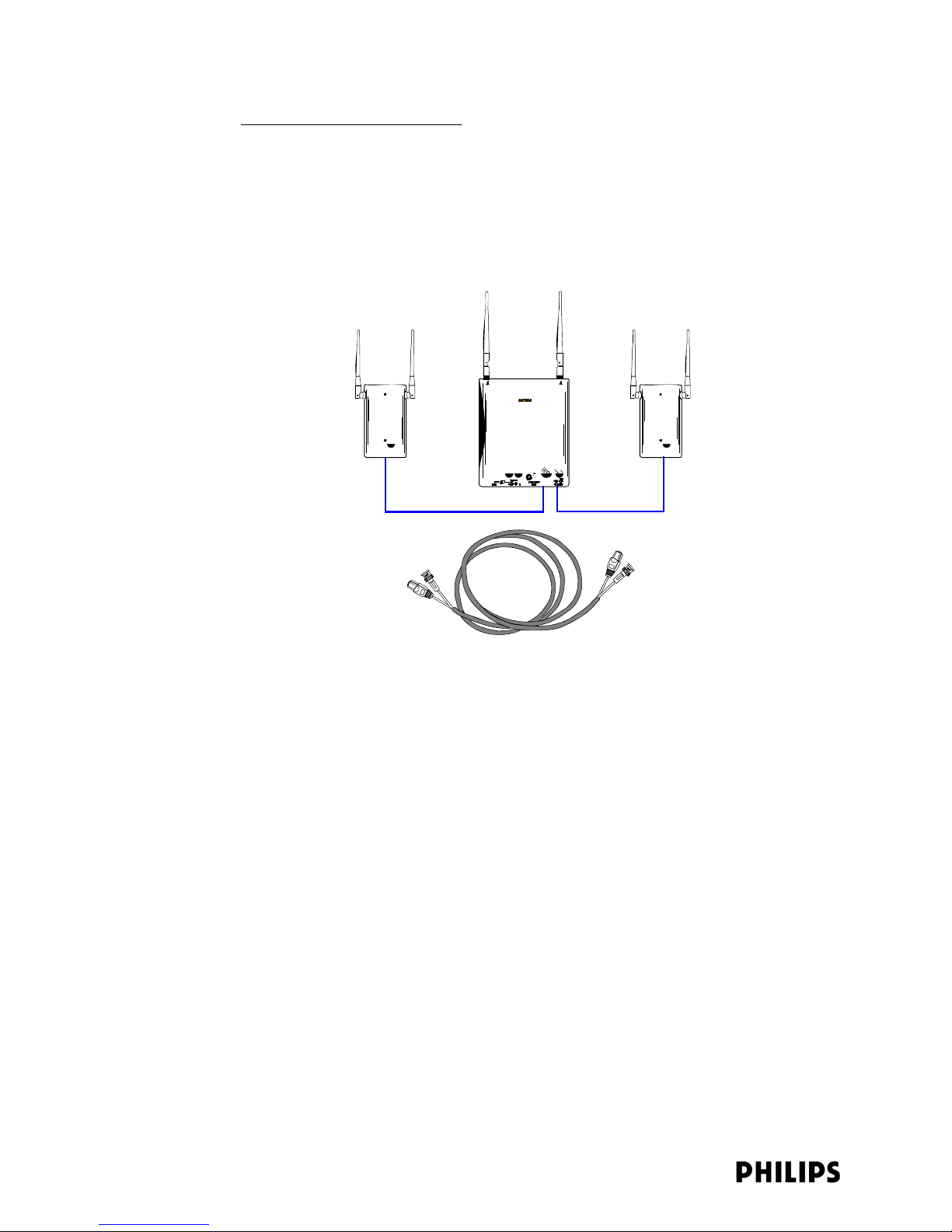
ITS Core Access
Points
The IntelliVue Telemetry System Core Smart-hopping Access Point (AP), Model
ITS4843A, (Figure 1-2) provides an air-link to transmit and receive data between ITS
wireless clients and the Philips IntelliVue Information Center via the ITS
infrastructure.
Core AP
Remote
Antenna
68 ft. Coax and
UTP Cable Bundle
Remote
Antenna
Figure 1-4: IntelliVue Telemetry System Core Access Point (Model ITS4843A)
The Core AP is a modular antenna infrastructure consisting of a Core AP (CAP) with
up to two connected Model ITS4846A Remote Antennas (RAs). A 68-foot (20.7m)
coaxial and unshielded twisted pair (UTP) cable bundle is used to connect a Remote
Antenna to a Core AP. Core APs are only available for the 1.4 GHz ITS.
The effective range of the Core AP and of each Remote Antenna is typically 32 feet.
The Core AP always supports a maximum of 18 wireless clients (i.e., patient-worn
transceivers or bedside monitors) regardless of its component configuration. A Core
AP alone supports 18 wireless clients. When used with a single RA, the Core AP
supports nine wireless clients and its connected RA supports nine wireless clients
(9+9=18). When used with two RAs, the Core AP supports six wireless clients and
its connected RAs each support six wireless clients (6+6+6=18).
When monitored patients are ambulatory, data roaming is handled seamlessly
between the other IntelliVue Access Points in the system. The Core AP and each RA
are always used with their two supplied antennas installed. The Core AP and its
attached Remote Antennas can be mounted out of the way on corridor walls, or
above or below ceiling tiles.
Philips provides ITS Core Access Points for the 1.4 GHz US Wireless Medical
Telemetry Service (WMTS) band (P/N 862228) with one or two optional Remote
Antennas.
1-6
Page 21
IntelliVue Telemetry System Infrastructure Components
ITS Core AP Connectors
Figure 1-5 shows the controls and connectors on the 1.4 GHz ITS Core AP and
Remote Antenna.
Coaxial Cable Connectors
Link LED
Activity LED
ITS Core Access Point
RA 2 RA 1
to Remote Antennas (2 & 1)
RA 2 RA 1
Ethernet Interface to
ITS Sync Unit
Connection LED
(Green)
UTP Cable Connector
to ITS Core AP
Power/Sync, Radio,
and Network
Status LEDs
ITS Remote Antenna
Serial Port
UTP Cable Connectors
to Remote Antennas (2 & 1)
with RA Status LEDs
Power LED
(Yellow)
Coaxial Cable Connector
to ITS Core Access Point
Figure 1-5: 1.4 GHz ITS Core AP and Remote Antenna Controls and Connectors
Note the following controls and connectors on the ITS Core AP:
• Ethernet Interface - The AP provides a 100 Base-T Ethernet interface with an
RJ-45 connector to connect the Core AP to the ITS Sync Unit.
The AP Ethernet interface provides data communications to and from the
IntelliVue Information Center over the ITS LAN infrastructure. It also presents
the 48Vdc power and synchronization signals required by the Core AP. The
synchronization signal is superimposed on the power supply voltage. You should
attach a ferrite block to the CAT 5 cabling (from the Sync Unit) no more than 20
inches (50 cm) from the RJ-45 connector to reduce electromagnetic (radiation)
interference. Table 1-1 lists the pin signals for the AP Ethernet interface.
• Serial Port - The serial port is used only for manufacturing purposes.
IntelliVue Telemetry System Infrastructure Installation and Service Guide 1-7
Table 1-2: AP Ethernet Interface Pin Signals
Pin Signal Description
1 Transmit Pair TX + Conductor
2 Transmit Pair TX - Conductor
3 Receive Pair RX + Conductor
4 + 48Vdc Power and Synchronization
5 + 48Vdc Power and Synchronization
6 Receive Pair RX - Conductor
7 0V Power Return
8 0V Power Return
Page 22

Chapter 1: Overview
Note If an installed, powered Remote Antenna becomes disconnected from its Core AP
• UTP Cable Connectors to Remote Antennas - Two standard RJ-45 connectors
are provided for the UTP cables that connect the Core AP to its Remote
Antennas. Each UTP cable carries 5.5 VDC power, Transmit and Receive control
signals, and Antenna Diversity signals to the Remote Antenna.
• Coaxial Cable Connectors to Remote Antennas - Two standard 75 Ohm
connectors are provided for the coaxial cables that connect the Core AP to its
Remote Antennas. Each coaxial cable carries RF and DC sense signals from the
Remote Antenna.
Note the following connectors on the Remote Antenna:
• UTP Cable Connector to Core AP - A standard RJ-45 connector is provided for the
UTP cable that connect the Remote Antenna to its Core AP. The UTP cable
carries 5.5 VDC power, Transmit and Receive control signals, and Antenna
Diversity signals from the Core AP.
• Coaxial Cable Connector to Core AP - A standard 75 Ohm connector is provided
for the coaxial cable that connects the Remote Antenna to its Core AP. The
coaxial cable carries RF and DC sense signals from the Core AP.
via its Coax/UTP cable bundle, you must reconnect the Coax/UTP cable bundle to
the RA and Core AP, and then cycle power to the connected Core AP before the RA
will re-establish communications with the Core AP.
ITS Core AP Status LEDs
The ITS Core AP provides the following status LEDs.
• Wired/Ethernet Activity - The Core AP provides two LEDs to indicate wired/
Ethernet activity to the ITS infrastructure. During normal operation, these LEDs
indicate the following information:
- Link LED - Link present/Ethernet connection. Lights GREEN (ON) when a
pass-through link is present - OFF when not present.
- Act LED - Transmit activity. Flashes YELLOW (ON) when there is activity is
over the wired network.
• Wireless/RF Activity - The Core AP provides three LEDs to indicate wireless/RF
activity. During normal operation, these LEDs indicate the following information:
- Power/Sync LED - GREEN (ON) when power and synchronization signal is
present.
- Radio LED - Normally OFF (not lit) - flashes green to indicate network activity.
- Network LED - Normally OFF (not lit) - flashes green to indicate network
activity.
At initial power on the AP runs a Power On Self-Test (POST). During the POST, the
above LEDs indicators flicker and then all three will illuminate continuously
(AMBER) to indicate correct startup operation. Then, the Power ON LED will
illuminate (GREEN) continuously to indicate that the 48Vdc power and sync
signal are being supplied, and the other two (AMBER) LEDs turn off (not lit).
1-8
Page 23
IntelliVue Telemetry System Infrastructure Components
• Remote Antenna - The Core AP provides two LEDs on each RJ-45 UTP cable
connector that provides status on a connected Remote Antenna:
- RA Connection - Lights GREEN to indicate a RA is connected to the Core AP.
- RA Power - Lights YELLOW to indicate connected RA is receiving power from
the Core AP.
The Remote Antenna provides the following status LEDs.
• Remote Antenna Status LEDs - The green and yellow LEDs above the
RJ-45 UTP cable connector to the Core AP provide status on the Remote
Antenna as summarized below.
Table 1-3: Remote Antenna Status LEDs
Green/Yellow LEDs Remote Antenna Status
Off/Off No connection to or power from Core AP.
Flash Green/Yellow Remote Antenna is running self-test/Power on.
Solid Green/Yellow Connection to Core AP is Successful/Power On.
This is the expected normal operational status.
Core AP
Mounting Options
Wall-mounting hardware is standard. An optional above/below ceiling mount kit is
available.
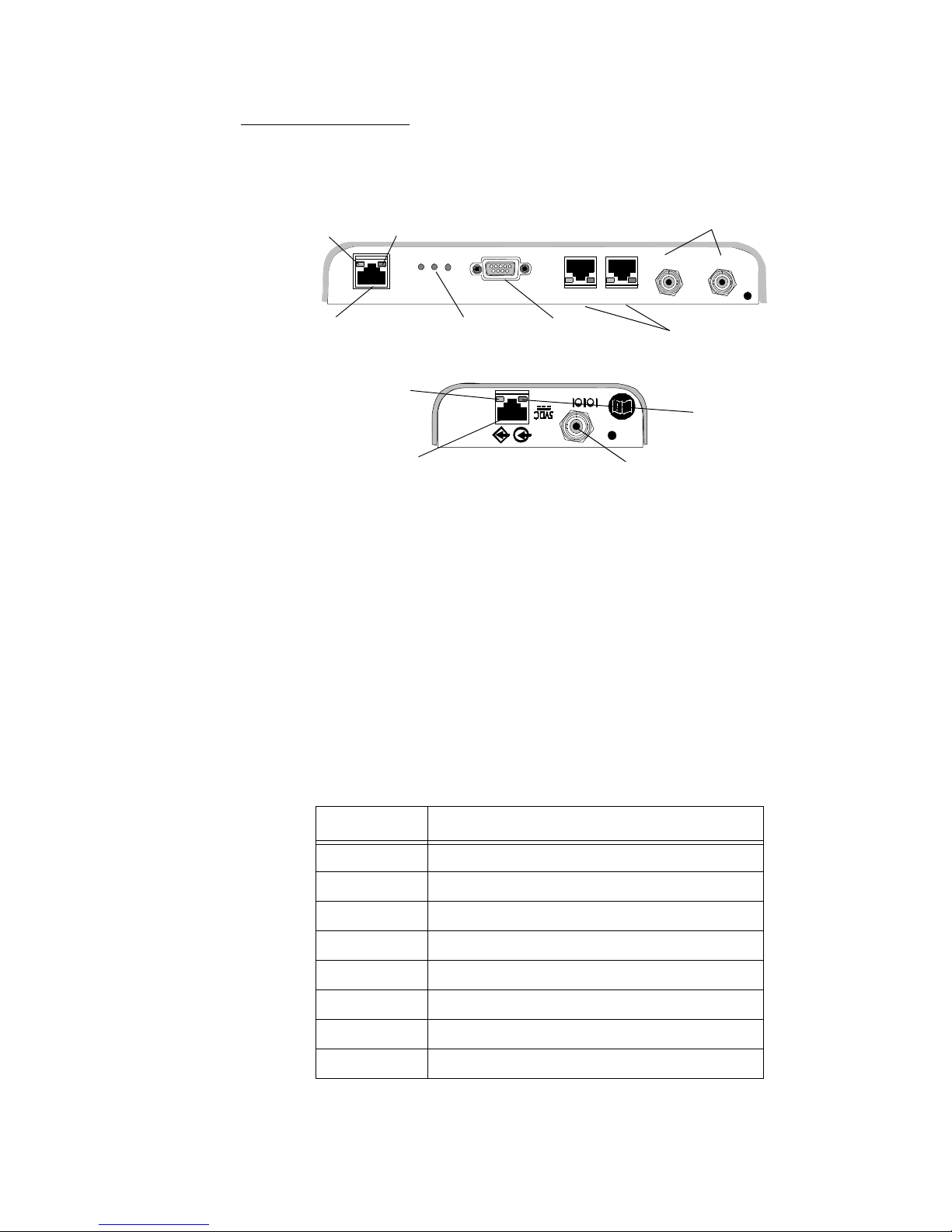
Access Point Controller
The multi-functional Philips Access Point Controller (APC) (Figure 1-6) controls the
data flow of patient-worn transceivers as the patients move about the coverage
area between the IntelliVue Access Points. It also can be used to configure
parameters of the APs—all via its Graphical User Interface (GUI).
Power LED
100-240V~
50/60 Hz,1.5A
Power Receptacle Serial Port Ethernet Port 100 Base-T LED
Network Utilization LEDs
100 Base-T
Link/ACT
Link/ACT LED
The APC provides System Alerts such as loss of synchronization, high data loss, AP
hardware failure, and over capacity. Additionally, when redundant APCs are
installed, the APC will provide a System Alert for APC hardware or software failure. It
can be rack mounted (recommended) or placed freestanding on a flat surface.
IntelliVue Telemetry System Infrastructure Installation and Service Guide 1-9
Figure 1-6: IntelliVue Telemetry System Access Point Controller
Page 24

Chapter 1: Overview
Front Panel
LEDs
The following status LEDs are provided on the APC front panel:
• Power LED - The Power LED is a multi-color LED that indicates the following
status:
- AMBER - During initialization, the Power LED is illuminated AMBER.
- GREEN - During normal operation, it is illuminated GREEN continuously.
- RED - If there is an internal problem with the APC, the Power LED will
illuminate RED. If the Power LED is lit RED, try recycling power to the APC. If it
remains lit RED, then the APC will need to be replaced
• Network Utilization LEDs - These LEDs provide indication (as a percentage) of
the amount of network traffic between the APC and the Access Points. When the
LED on the far left is ON but the rest are OFF, the network utilization is low, less
than 20%. As the amount of traf fic increases, more LEDs will turn ON to indicate
an increase in the percentage of network utilization. When all six LEDs are ON,
the network utilization is greater than 90% of the AP Controller’s total capacity.
The utilization value is updated ten times per second. In addition, the LEDs
indicate the peak utilization for the previous three seconds by illuminating the
LED that corresponds to that utilization percentage. For example, you may
notice that all six LEDs turn ON momentarily and then the fourth and fifth turn
OFF while the sixth remains ON. The sixth LED is ON to indicate peak utilization
reached 90% within the last three seconds.
Rear Panel
Connectors and
LEDs
The following connectors and status LEDs are provided on the APC rear panel:
• Power Receptacle - Connect the APC an AC power source that provides 100 240 VAC, 1.5A max, at 50/60Hz.
• Serial Port - Use the APC serial port to connect your service PC to the APC
command line interface (CLI) to complete basic initial configuration the APC.
• Ethernet Port - The APC provides a 100 Base-T Ethernet interface with an RJ-45
connector to connect the APC to an available port on the ICN network switch.
• 100 Base-T LINK LED - Illuminates GREEN continuously when the APC has
established a 100 Mbps (NORMAL) connection. The LED is OFF when the APC
has established a 10 Mbps connection.
• LINK/ACT LED - This LED reflects link integrity as well as activity. When the
Ethernet LAN cable is physically connected to the Ethernet LAN (RJ-45
receptacle), the LED will illuminate YELLOW. When the cable is attached the
LED will remain ON/lit, and when there is activity, at which time the LED will
blink OFF momentarily. If there is a problem with the link, then the LED will
remain OFF (although the LED will blink ON momentarily when the unit attempts
to send data through its Ethernet port). A problem with an Ethernet link is
typically due to a damaged or improper Ethernet cable, or to a damaged port on
one of the linked devices.
1-10
Page 25
IntelliVue Telemetry System Infrastructure Components
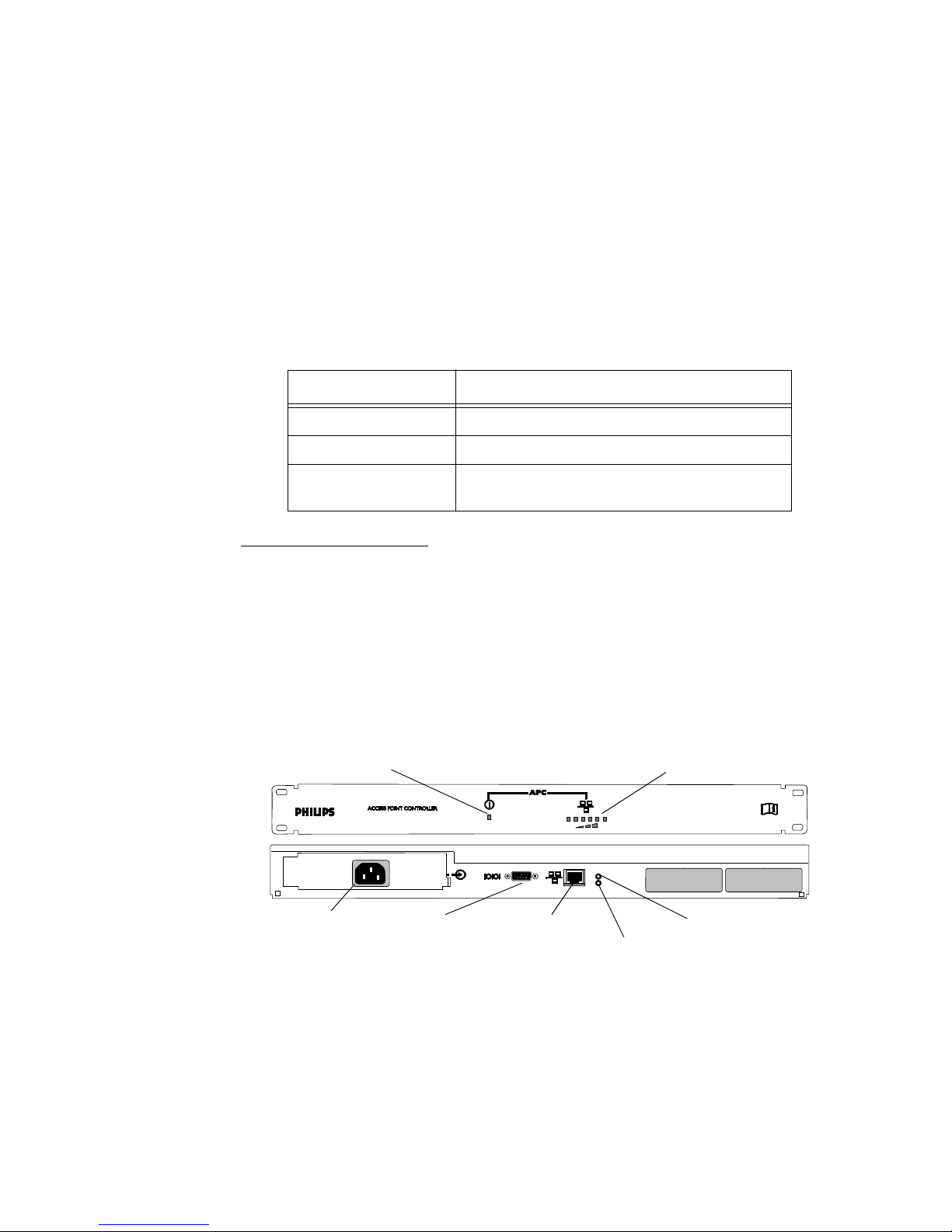
Synchronization Unit
The Philips Synchronization Unit (Sync Unit) (Figure 1-7) provides a necessary
common clock signal to synchronize all the IntelliVue Access Points in the system.
Access Points need to be synchronized so that as the patients move around the
hospital they are able to maintain and hand over connections between the Access
Points seamlessly without interruption.
Master/Slave Switch
FROM POWER HUB (PoE Unit)
1 2 3 4 5 6 7 8 9 10 11 12
1 2 3 4 5 6 7 8 9 10 11 12
AP/SU (to APs or slave SUs)
Power Receptacle
TO SLAVE SU TO MASTER SU
FROM
POWER
HUB
AP/SU
Power LED EXT REF. LED SYNC IN LED
TO
SLAVE SU
TO
MASTER SU
POWER EXT REF SYNC. IN
Cable Delay Switch
MASTER
CABLE DELAY
SLAVE
EXT. 10MHz REF.
6
5
7
4
8
9
3
2
10
1
Front-panel
Connectors,
Controls, and
Indicators
Figure 1-7: IntelliVue Telemetry System Sync Unit
The Sync Unit can be rack mounted (recommended) or placed freestanding on a flat
surface.
Each Sync Unit provides synchronization for up to 12 Access Points (AP). Maximum
cable length between a Switch/PoE Unit/Sync Unit/Access Point is 100m (328ft.)
(normal LAN Ethernet rules).
The Sync Unit provides the following front-panel connectors, controls, and
indicators:
• FROM POWER HUB (PoE Unit) - Top row of connectors. 1 to 12 input RJ-45
connectors, power inputs (48VDC) from the PoE unit, as well as 100Base-T
Ethernet.
• AP/SU (to APs or slave SUs) - Bottom row of connectors. 1 -12 ‘main’ output RJ45 sockets, to APs carrying power (48VDC) and synchronization as well as 100base-TX Ethernet. These can feed APs or slave Sync Units.
• TO SLAVE SU - Output RJ-45 port carrying synchronization signal to a slave Sync
Unit. Category 5 (or greater) UTP cable length attached between this output and
the input of the upstream Sync Unit can be up to 500m.
• TO MASTER SU - Input RJ-45 socket designed to connect to the output of
another Sync Unit. This can be either the ‘to slave’ or a ‘main’ output of the
upstream unit
• POWER LED - Lights green when AC power is present.
• EXT REF. LED - Always off as this LED is not used currently.
• SYNC IN LED - LED should be OFF if this Sync Unit is the Master. LED is lit
GREEN if unit is a Slave.
IntelliVue Telemetry System Infrastructure Installation and Service Guide 1-11
Page 26
Chapter 1: Overview
• MASTER/SLAVE Toggle Switch - MASTER/SLAVE toggle switch (set manually) to
indicate the master SU of an installation. This MASTER switch disables the
alarm that would be generated by the lack of an upstream unit to provide a
reference signal to this unit. Slave units should receive a reference feed from a
master SU, and should be switched to the SLAVE position (operation). If the
reference feed fails, these units will free-run, and will also generate a technical
alarm.
• CABLE DELAY Switch - 10 Position rotary step switch compensates for cable
delay - lowest delay position 1 to highest delay position 10. Each switch
increment represents 50 m cable length.
• EXT 10MHz REF - Not used currently.
Rear-panel
Connectors
The Sync Unit has a single rear-panel connector, its AC power cord receptacle.
Connect the Sync Unit to an AC power source that provides 100 - 240 VAC, 1.5A
max, at 50/60Hz (autoranging).
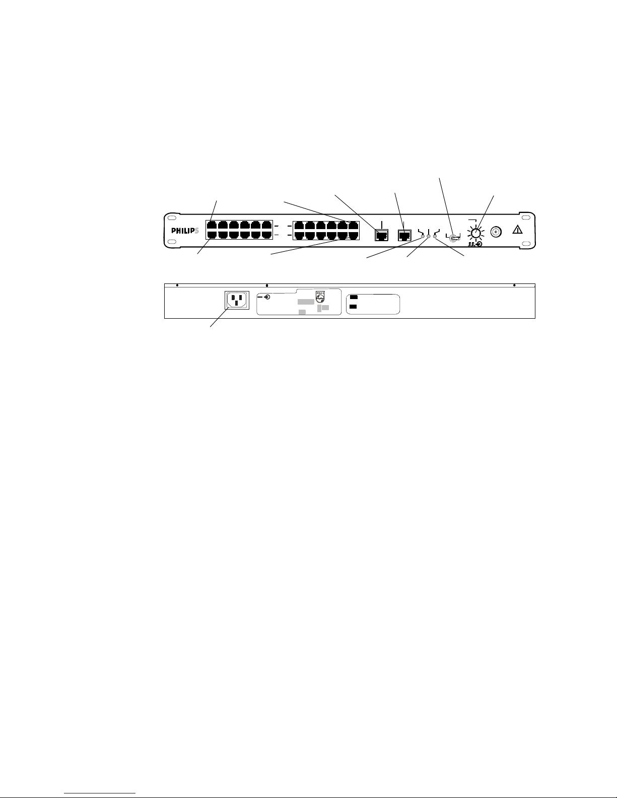
Power over Ethernet Unit
The ITS Power over Ethernet (PoE) Unit is a 6- or 12-port Power-over-Ethernet device
that provides 48 VDC power to IntelliVue Access Points (and also remote Sync Units
if connected) via 100-Base-TX Ethernet LAN cabling.
Data and Power Ports (To APs/SUs)
Data Ports (To ICN Network Switch)
Figure 1-8: IntelliVue Telemetry System 12-port Power Over Ethernet Unit
The ITS PoE Unit can be rack mounted (recommended) or placed free standing on a
desktop.
Uninterruptible Power Supply
The ITS infrastructure has several components that must be powered from an
Uninterruptible Power Supply (UPS) including the APC, the PoE Unit, the Sync Unit,
and network switches and routers. The UPS supplies backup power to protect
against hospital generator changeover interruptions, and short power line
transients.
The UPS can be rack mounted (recommended) or placed free standing on a
desktop.
1-12
Figure 1-9: Uninterruptible Power Supply
Page 27

General Intellivue Telemetry System Data Flow
Refer Table 1-4 to when connecting ITS infrastructure devices to the UPS to ensure
that you do not exceed the UPS’ backup power capacity.
Table 1-4: ITS Device Power Requirements
Product
Number
862114 Sync Unit 10 Watts
862152 PoE Unit – 12 Port 165 Watts
862149 PoE Unit – 6 Port 90 Watts
862161 Cisco 2950 Switch: Copper 30 Watts
862162 Cisco 2950 Switch: Fiber 30 Watts
862084 HP 2524 Switch 36 Watts
862163 Cisco 3550 Router: Copper 65 Watts
862164 Cisco 3550 Router: Fiber 85 Watts
862147 APC 10 Watts
ITS Infrastructure Device Power in Watts
General Intellivue Telemetry System Data Flow
Data sent from the ITS transceiver to the IntelliVue Information Center traverses the
network as follows:
1. The transceiver sends its ECG data over the wireless link to an ITS Access Point.
2. The AP then “wraps” the ECG data into another message packet, with its
destination as the Access Point Controller that is assigned to handle the
management activities for that AP.
3. The wired network then treats the packet like a message to the APC.
4. The APC receives the packet, “unwraps” it and determines that the message is
for the IntelliVue Information Center.
5. The APC repackages the message and forwards it on with a destination address
of the IntelliVue Information Center.
Data sent from the IntelliVue Information Center to a patient-worn transceiver
traverses the network as follows:
1. The Information Center sends a message to the transceiver’s IP address. The
network “sees” the location of the transceiver’s IP address as the location of
the APC, and sends the message there.
2. The APC then looks at the message, determines which ITS Access Point is
currently connected to the transceiver it needs to send the message to, “wraps”
the message into a packet and forwards the packet on to the appropriate ITS
Access Point.
3. The network handles the packet as a message for the ITS Access Point.
IntelliVue Telemetry System Infrastructure Installation and Service Guide 1-13
Page 28

Chapter 1: Overview
4. When the packet arrives at the ITS Access Point, the Access Point “unwraps” the
message, determines which transceiver the message is intended for, and sends
the message on to the transceiver over the wireless link.
Defined ITS Bandwidth
The ITS transceivers (portable patient-worn devices), wireless bedside monitors,
and infrastructure operate on the 1.4 GHz US Wireless Medical Telemetry Service
(WMTS) band or on the 2.4 GHz band for deployments outside of the US.
1.4 GHz ITS Bandwidth
In the United States, the IntelliVue Telemetry System operates in the radio bands of
1395 – 1400 MHz and 1427 – 1429.5 MHz. The FCC has designated this spectrum
(WMTS) for use by Medical Telemetry devices.
Standard WMTS
Channels
Carved-out
Areas
WMTS operations are accorded primary status over non-medical telemetry
operations in 1395-1400MHz and 1427-1429.5 MHz bands, but under certain
extenuating circumstances, medical telemetry may also be permitted to operate in
the 1429.5 - 1432 band. Table 1-5 lists the standard 1.4GHz WMTS channels.
Table 1-5: Standard Primary and Secondary WMTS Channels
Frequencies
Channels
Low Center High
Primary Channels
Channel 1 1395.0977MHz 1395.8977MHz 1396.6977MHz
Channel 2 1396.6970MHz 1397.4970MHz 1398.2970MHz
Channel 3 1398.2963MHz 1399.0963MHz 1399.8963MHz
Channel 4 1427.0979MHz 1427.8979MHz 1428.6979MHz
Secondary Channels (Extenuating Circumstances Only)
Channel 5 1428.6972MHz 1429.4972MHz 1430.2972MHz
Channel 6 1430.2965MHz 1431.0965MHz 1431.8965MHz
The FCC has carved the following metropolitan regions out of the standard WMTS
spectrum to protect operation of critical RF devices (e.g., radar, military and
government communications, etc.):
• Pittsburgh, PA
• Metro Washington D.C.
• Richmond/Norfolk, VA
•Austin/Georgetown, TX
•Battle Creek, MI
•Detroit, MI
•Spokane, WA
In these seven areas, in contrast to the rest of the US, WMTS has primary status in
the 1429-1431.5 MHz band, but is secondary to non-medical telemetry operations
1-14
Page 29

Defined ITS Bandwidth
in the 1427-1429 MHz band. Table 1-6 lists the 1.4GHz WMTS channels available
for use in “carved-out areas.”
Table 1-6: Primary and Secondary WMTS Channels for “Carved-out Areas”
Frequencies
Channels
Low Center High
Primary Channels
Channel 1 1395.0977MHz 1395.8977MHz 1396.6977MHz
Channel 2 1396.6970MHz 1397.4970MHz 1398.2970MHz
Channel 3 1398.2963MHz 1399.0963MHz 1399.8963MHz
Channel 4a 1429.4410MHz 1430.2410MHz 1431.0410MHz
Secondary Channel
Channel 4
a
a. Channel 4 is not available when special “Carved-out” geographic area is
selected on the APC.
1427.0979MHz 1427.8979MHz 1428.6979MHz
Required FCC
Registration
The FCC (Section 95.1111 of the FCC Rules) requires that all WMTS transmitters be
registered with the American Society for Healthcare Engineering (ASHE). If a
hospital doesn’t register, not only is it subject to being interfered with, but the FCC
can also shut down its telemetry system.
Hospitals using the IntelliVue telemetry System must register all 1.4 GHz patientworn transceivers, wireless bedside monitors, and Access Points and Remote
Antennas.
Site registration with the frequency coordinator, American Society for Healthcare
Engineering (ASHE), is only required once and can be done online (www.ashe.org).
The frequencies and number of devices in use must be logged with the frequency
coordinator.
2.4 GHz ITS Bandwidth
Outside of the United States, the IntelliVue Telemetry System uses RF energy in the
2.4 GHz frequency space across 48 radio channels assigned from 2401.066 MHz
to 2482.272 MHz, with a channel spacing of 1.728 MHz.
Table 1-7 lists the 2.4 GHz ITS channels.
Table 1-7: 2.4 GHz ITS Channels
2.4 GHz ITS Channel
(for Advanced Selection)
Center Frequency
(MHz)
IntelliVue Telemetry System Infrastructure Installation and Service Guide 1-15
0 2401.056
1 2402.784
2 2404.512
3 2406.240
4 2407.968
Page 30

Chapter 1: Overview
Table 1-7: 2.4 GHz ITS Channels
2.4 GHz ITS Channel
(for Advanced Selection)
5 2409.696
6 2411.424
72413.152
82414.880
92416.608
10 2418.336
11 2420.064
12 2421.792
13 2423.520
14 2425.248
15 2426.976
16 2428.704
17 2430.432
18 2432.160
Center Frequency
(MHz)
19 2433.888
20 2435.616
21 2437.344
22 2439.072
23 2440.800
24 2442.528
25 2444.256
26 2445.984
27 2447.712
28 2449.440
29 2451.168
30 2452.896
31 2454.624
32 2456.352
33 2458.080
34 2459.808
1-16
35 2461.536
Page 31

Table 1-7: 2.4 GHz ITS Channels
Defined ITS Bandwidth
2.4 GHz ITS Channel
(for Advanced Selection)
36 2463.264
37 2464.992
38 2466.720
39 2468.448
40 2470.176
41 2471. 904
42 2473.632
43 2475.360
44 2477.088
45 2478.816
46 2480.544
47 2482. 272
Center Frequency
(MHz)
The 2.4 GHz ITS channels available at a given installation site vary by geographic
region as determined by the regulatory domain for that region. Table 1-8 lists the
available 2.4 GHz ITS channels, maximum Effective Isotropic Radiated Power
(EIRP), and regulatory domain by geographic region.
Table 1-8: Available 2.4 GHz ITS Channels by Geographic Region
Allowed
Region
Europe 1 - 46 ETSI
South America 1 - 46 ETSI
Asia 1 - 46 ETSI
Africa 1 - 46 ETSI
Canada 0 - 47 RSS-210
Japan 0 - 47 ARIB
Tai wan 0 - 47 FC C
Australia/
New Zealand
2.4 GHz
Channels
1 - 46 Aus/NZ
Regulatory
Rule
IntelliVue Telemetry System Infrastructure Installation and Service Guide 1-17
Page 32

Chapter 1: Overview
Supported Topologies and System Limits
The IntelliVue Telemetry System is installed as part of an overall IntelliVue Clinical
Network installation. There are two basic IntelliVue Clinical Network topologies into
which the IntelliVue Telemetry System can be installed:
•non-routed ICN topology
•routed ICN topology
Installing the ITS within a Non-routed ICN
In a non-routed ICN configuration, the ICN functions as an independent network
with a single IntelliVue Database (DBS) Domain. Figure 1-10 represents an ITS
installed in a non-routed ICN.
Note the following guidelines for installing the ITS within a non-routed ICN topology:
• All ITS wireless devices (transceivers/wireless bedside monitors) must reside on
the ICN Database Domain on which the ITS infrastructure is installed.
• Up to 48 ITS Standard or Core Access Points may be installed on a non-routed
ICN topology.
• The 2.4 GHz ITS may only be installed on a non-routed ICN topology.
1-18
Figure 1-10: An ITS Installed within a Non-routed ICN Topology
Page 33

Supported Topologies and System Limits
• Multiple ITSs at a single hospital are supported only if the topology,
configuration, and Sync Network requirements listed in Appendix A are met.
Figure 1-11 illustrates supported and non-supported ITS installations within a nonrouted ICN topology.
Supported:
(Multiple ITSs at a single
location are supported
only if the Topology,
Configuration, and Sync
Net requirements listed
in Appendix A are met.)
Not Supported:
Figure 1-11: Supported and Non-Supported ITS Non-routed ICN Installations
Refer to Table 1-9 for a list of the device IP address assignments used in a nonrouted ICN configuration where the ITS infrastructure is installed on the ICN subnet.
Note the following regarding Table 1-9:
• “n” represents the network number and starts at 0 for single Database Domain
ICN systems. This variable increments by 8 from there for additional ICN
Database Domains. For example, for DBS 2, “n” would equal 8, for DBS 3, “n”
would equal 16, and so on.
IntelliVue Telemetry System Infrastructure Installation and Service Guide 1-19
Page 34

Chapter 1: Overview
Table 1-9: IP Address Assignments for Non-routed ICN Subnet
Device Types
(with Non-routed Subnet)
Network Subnet Address 172.31.n.0 Left Blank (0.0.0.0)
Reserved for Routed Solution 172.31.n.1 - 3
Reserved for Service PC 172.31.n.4 - 9 IP Address of DBS or
Network Switches and Remote
Client Infrastructure (i.e.,
Remote Client Router)
Reserved for Future Use 172.31.n.103 - 255
1.4/2.4 Ghz ITS APCs 172.31.(n+1).0 - 63 IP Address of DBS or
Reserved 172.31.(n+1).64 - 127
Reserved 172.31.(n+1).128 - 255
1.4GHz AP Static Range 172.31.(n+2).0 - 127 IP Address of DBS or
Bootp/DHCP Server Range 2 for
1.4Ghz APs (configured in APC)
IP Addresses
Subnet Mask:
255.255.248.0
M3150 Information Center
172.31.n.10 - 102 IP Address of DBS or
M3150 Information Center
M3150 Information Center
M3150 Information Center
172.31.(n+2).128 - 255 IP Address of DBS or
M3150 Information Center
Default
Gateway
Database server (NIC 1) 172.31.(n+3).0
Application Server (NIC 1) 172.31.(n+3).16 - 31 IP Address of DBS or
M3150 Information Center
Information Centers (NIC 1) 172.31.(n+3).32 - 63 IP Address of DBS or
M3150 Information Center
Information Center Clients 172.31.(n+3).64 - 95 IP Address of DBS or
M3150 Information Center
Printers (Set by BootP in DBS) 172.31.(n+3). 96 - 127 IP Address of DBS or
M3150 Information Center
Reserved 172.31.(n+3).128 - 255
Bedside Monitors/Devices
(Wired & ISM 2.4 GHz Wireless)
Reserved for Future Use 172.31.(n+5).0 - 255
Bootp/DHCP Server Range 1 for
1.4/2.4 GHz ITS Transceivers/
Bedsides (config in APC)
Reserved for Future Use 172.31.(n+7).0 - 254
Network broadcast address 172.31.(n+7).255
172.31.(n+4).0 - 255 IP Address of DBS or
M3150 Information Center
172.31.(n+6).0 - 255 IP Address of DBS or
M3150 Information Center
1-20
Page 35

Supported Topologies and System Limits
Installing the ITS on a Routed ICN Topology
In a routed ICN configuration, the ITS infrastructure is installed as a separate
subnet to which multiple ICN Database Domains have access via routers. Figure 112 represents an ITS installed within a routed ICN topology.
IntelliVue Telemetry System Infrastructure Installation and Service Guide 1-21
Figure 1-12: An ITS Installed within a Routed ICN Topology
Page 36

Chapter 1: Overview
Note the following guidelines for installing the ITS within a routed ICN topology:
• An ITS subnet can be connected up to 22 ICN Database Domains via routers.
• Up to 320 ITS Standard Access Points may be installed on a routed ICN
topology.
• Up to 320 ITS Core Access Points and up to 640 Remote Antennas (i.e., two per
Core AP) may be installed on a routed ICN topology.
• ITS Standard and Core APs may exist together on a routed ICN topology so long
as the maximum number of APs does not exceed 320.
• Only the 1.4 GHz ITS may be installed within a routed ICN topology. The 2.4 GHz
ITS does not support installation within a routed ICN topology.
Refer to Table 1-10 for a list of the device IP address assignments used in a routed
ICN configuration where the ITS infrastructure is installed as a separate subnet to
which up to 22 Database Domains have access via routers.
Note the following regarding Table 1-10:
• “n” represents the network number and starts at 0 for single ICN systems (i.e.,
Database Domains). This variable increments by 8 from there for additional
IntelliVue Clinical Networks. For example, for ICN 2, “n” would equal 8, for ICN 3,
“n” would equal 16, and so on.
• Route statements are generated (in instances with a Router and without) at the
completion of the Config Wizard.
1-22
Page 37

IntelliVue Telemetry System Infrastructure Installation and Service Guide 1-23
Supported Topologies and System Limits
Table 1-10: Routed Topology ICN and ITS Subnet Device IP Addresses
Device Types
(with Routed Subnet)
ICN Subnet IPs
Mask: 255.255.248.0
Default
Gateway
Wireless Subnet IPs
Mask: 255.255.240.0
Default
Gateway
Network Subnet Address (Used in Config Wizard for Router) 172.31.n.0 172.31.240.0
Gateway Address 172.31.n.1 172.31.240.1
Router A – <used for ITS Wireless Subnet Router> 172.31.n.2 172.31.240.2 172.31.240.1
Router B – <used for ITS Wireless Subnet Router> 172.31.n.3 172.31.240.3 172.31.240.1
Reserved for Service PC 172.31.n.4 - 9 172.31.n.1 172.31.240.4-9 172.31.240.1
Network Switches and Remote Client Infrastructure 172.31.n.10 - 102 172.31.n.1 172.31.240.10 – 20 172.31.240.1
Reserved for Future Use 172.31.n.103 - 255 172.31.240.21 – 172.31.240. 255
ITS APCs 172.31.(n+1).0 - 63 172.31.n.1 172.31.241.0 – 127 172.31.240.1
Reserved 172.31.(n+1).64 - 127
Reserved 172.31.(n+1).128 - 255
ITS AP Static Range (1.4/2.4 GHz) 172.31.242.0 – 172.31.244.127 172.31.240.1
ITS APC Bootp/DHCP Server Range 2 for 1.4/2.4 GHz APs 172.31.244.128 - 172.31.246.255 172.31.240.1
Database Server (NIC 1) 172.31.(n+3).0 - 15 Default blank
Application Server (NIC 1) 172.31.(n+3).16 - 31 172.31.n.1
Information Centers (NIC 1) 172.31.(n+3).32 - 63 172.31.n.1
Information Center Clients 172.31.(n+3).64 - 95 172.31.n.1
Printers (Set by BootP) 172.31.(n+3). 96 - 127
Reserved 172.31.(n+3).128 - 255 172.31.247.0 - 255
Bedside Monitors/Devices (Wired & ISM 2.4GHz) (Set By BootP) 172.31.(n+4).0 - 255
Reserved for Future Use 172.31.(n+5).0 - 255
ITS APC Bootp/DHCP Server Range 1 for Transceivers/Bedsides 172.31.248.0 – 172.31.253.255 172.31.240.1
Reserved for Future Use 172.31.(n+7).0 - 254 172.31.254.0 – 172.31.255.254
Network Broadcast Address 172.31.(n+7).255 172.31.255.255
Page 38

Chapter 1: Overview
System Limits
Note the following important ITS system limits.
Table 1-11: Maximum ITS Capacities
ITS Device Maximum Supported
Access Point Controllers 9 (includes one for redundancy)
1.4 GHz Standard Access Points 320 (routed ICN topology)
48 (non-routed ICN topology)
1.4 GHz Core Access Points
1.4 GHz Remote Antennas
2.4 GHz Access Points 2.4 GHz ITS does not support routed ICN topology.
1.4 GHz Patient-worn Transceivers 1024 (routed ICN topology)
2.4 GHz Patient-worn Transceivers 2.4 GHz ITS does not support routed ICN topology.
320 (routed ICN topology)
48 (non-routed ICN topology)
640 (routed ICN topology)
96 (non-routed ICN topology)
48 (non-routed ICN topology)
128 (non-routed ICN topology)
128 (non-routed ICN topology)
IntelliVue Telemetry System Specifications
This section lists power, radio, and regulatory compliance specifications for the
IntelliVue Telemetry System.
Power Requirements
Table 1-12: ITS Component Power Requirements
Device/
Component
Input Voltage
(VAC/ VDC)
Manual
Switching
Required?
Input
Frequency
(Hz)
Dissipated
Power
(Max - Watts)
Standard or Core
Access Point
SYNC Unit 88-264 VAC No 47-63 < 10W/18VA
POE with 1 AP 88-264 VAC No 47-63 <
POE with 12 AP 88-264 VAC No 47-63 <
Access Point
Controller
1-24
48 VDC Nominal
(44 - 52) VDC
287 mA
88-264 VAC No 47-63 <
No DC <
13.8W
20W/50VA
165W
10W/40VA
Page 39

IntelliVue Telemetry System Specifications
Table 1-13: UPS Specifications
UPS
Requirements
Input Voltage 1.4 GHz ITS 2.4 GHz ITS
120VAC +/-10% 100, 120, 127, 220, 240 VAC ± 10%
Input
Frequency
UPS AC
Input Port
Number of UPS
AC output ports
Power delivery UPS shall provide at least 225Watts for >
Power Fail
Tran si tio n
60Hz +/-3Hz minimum 50, 60Hz +/-3Hz
100, 120VAC model: one NEMA 5-15P plug.
230 VAC model: one IEC 320 C14 plug.
100, 120VAC model: 3 minimum (NEMA 5-15R output receptacles),
desirable to have 5 ports or greater.
230V model: 3 minimum (IEC 320 C13 output receptacles), desirable
to have 5 ports or greater.
12 APs, 1 Sync Unit, 2 APC, 1 POE, & 1 Switch from one UPS unit with 5
UPS ports.
Or:
12 APs, 1 Sync Unit, 1 APC, 1 POE, from one UPS unit with 3 UPS ports.
Additional UPS would be needed to power redundant APC & Switch.
UPS must be responsive to power fail conditions such that ITS system
does not experience reboot due to transition to temporary battery
backup power.
Parameter Specification
90 seconds to power
Power Fail Alert UPS shall provide local auditory response to power fail conditions.
EMI Filtering Provide AC line EMI filtering over 100KHz to 30MHz on UPS ports.
EMC FCC part 15 class A or B certification, CE Mark: CISPR 22/ EN 55022,
and CISPR 24 / EN 55024.
Safety UL certification, EN 62040 (Low Voltage Directive).
Mounting Rack Mounting is desirable.
IntelliVue Telemetry System Infrastructure Installation and Service Guide 1-25
Page 40

Chapter 1: Overview
Radio Compliance Specifications
Table 1-14: 1.4 GHz ITS FCC Compliance Specifications
FCC Specification
47C F R 95, su b -part H,
WMTS Services
47CFR 15, sub-part C 15.203 Antenna requirement Standard and Core
47CFR 15, sub-part B,
Unintentional
Radiators
47CFR 15, sub-part A,
General
Relevant
Paragraphs
95.1115,
95.1125,
95.1109
15.101,
15.105,
15.107, 15.109
15.19
15.31, e)
15.33, 1)
15.35, c)
Content Device
Field strength limits,
Undesired emissions
Emission types, Channel use,
Frequency stability, Labeling
General labeling & user
information Conducted &
Radiated limits
Required labeling,
Allowed RF power variation,
Allowed RF harmonic
radiation, RF power
measurement is averaged
over one complete pulse
train for pulsed operation
Patient-worn
Tra nsc eive r,
Standard and Core
Access Point
powered by POE
Unit.
Access Point
Sync Unit, PoE Unit,
and APC
Sync Unit, PoE Unit,
and APC
Safety Regulatory Compliance
Table 1-15: ITS Infrastructure Safety Standard Compliance
Safety Specification Compliant ITS Device/Component
Information Technology Equipment - Safety
IEC 60950-1:2001
(1st Edition)
UL 2043: 2003
U.S. National Electrical Code
NFPA 70:2002,
Paragraph 300.22, Subpart C
Standard for Uninterruptible Power Supply
Equipment
UL 1778:First Edition, 23-Nov-92 with revisions
dated 6-Dec-93, 4-Feb-94, 19-Jul-94
Standard and Core Access Points, APC, and
Sync Unit, PoE Unit, Switches, Routers, UPS.
1.4 GHz Core APs and Remote Antennas
installed in air-handling spaces.
Standard 1.4 GHz and 2.4 GHz Access
Points installed in air-handling spaces
comply when installed within a compliant
enclosure available from Philips.
“Air-handling spaces” include the areas
above dropped ceilings. These spaces are
not to be confused with “plenum,” which
refers to air ducts. ITS APs are not mounted
in plenum space.
UPS.
1-26
Page 41

IntelliVue Telemetry System Specifications
Environmental Specifications
For EMC purposes component parts of the system conform to the requirements of
EN60601-1-2:2001.
In general, the ITS is designed for use in an indoor environment and operates over
an ambient temperature range of 0
transceiver.
The Access Point, Sync Unit, APC, and Power over Ethernet Unit, and switches are all
classified as ITE devices.
Table 1-16: ITS Environmental Specifications
° to 55° C, excluding the patient-worn
Environmental Test for ITS Test Type & Limits
Operating Temperature
Operating Humidity
Storage Temperature
Storage Humidity
Altitude (Operating and
Non-operating)
0
° to 55° C
< 95% RH at 40°C (104°F)/
non-condensing
° C to 60° C
-40
< 90% RH at 60° C
3,048 meters (10,000 ft) Standard and Core
Applicable System
Element
Standard and Core
APs, Remote
Antennas, Sync
Unit, APC
Standard and Core
APs, Remote
Antennas, Sync
Unit, APC
Standard and Core
APs, Remote
Antennas, Sync
Unit, APC
Standard and Core
APs, Remote
Antennas, Sync
Unit, APC
APs, Remote
Antennas, Sync
Unit, APC
IntelliVue Telemetry System Infrastructure Installation and Service Guide 1-27
Page 42

Chapter 1: Overview
IntelliVue Telemetry System Infrastructure Product Numbers
Table 1-17 lists key product numbers associated with the IntelliVue Telemetry
System infrastructure.
Table 1-17: ITS Infrastructure Product Numbers
Device/Option
Access Point Controller 862147
ITS Synchronization Unit 862114
6-port Power over Ethernet Unit 862149
12-port Power over Ethernet Unit 862152
Model M4842A IntelliVue 1.4 GHz Standard Smart-Hopping Access Point 862113
Model ITS4843A IntelliVue 1.4 GHz Core Smart-Hopping Access Point 862228
Model ITS4852A IntelliVue 2.4 GHz Standard Smart-Hopping
Access Point
IntelliVue 1.4 GHz Telemetry Transceiver
•ECG Option
• ECG/SpO2 Option
• ECG Upgradeable Option
IntelliVue 2.4 GHz Telemetry Transceiver
•ECG Option
• ECG/SpO2 Option
• ECG Upgradeable Option
IntelliVue Telemetry System Mounting Options
• One Remote Antenna (Model # ITS 4846A) for 862228
• Two Remote Antennas (Model # ITS 4846A) for 862228
• Wall-mount Option for 862113 and 862232
• Above Ceiling Tile-Mount Option for 862113 and 862232
• Below Ceiling Tile-Mount Option for 862113 and 862232
• Wall and Shallow Rack Mount for APC (862147) and
Sync Unit (862114)
• Above & Below Ceiling Tile-mount Option for 862228
6N Product Number/
Option Number
862232
862439
•S01
•S02
•S03
862231
•S01
•S02
•S03
862415
•C01
•C02
•K01
•K02
•K03
•K04
•K05
1-28
Page 43

2
Planning Your ITS Deployment
Locating the IntelliVue Telemetry System Access Points and supporting
infrastructure to assure full coverage for all patient-worn transceivers and
wireless bedside patient monitors requires careful site planning.
This chapter provides information and procedures that must be followed to
ensure a successful IntelliVue 1.4 GHz or 2.4 GHz ITS deployment
including:
• Respecting Patient Care Boundaries
• General ITS Infrastructure Site Planning Guidelines
• Performing a Physical Space Assessment
• Planning the Sync Network Layout
• Planning Your AP Groupings
• Performing an RF Assessment
• Assigning 2.4 GHz ITS Channels
• Completing ITS Installation Worksheets
IntelliVue Telemetry System Infrastructure Installation and Service Guide 2-1
Page 44

Chapter 2: Planning Your ITS Deployment
Respecting Patient Care Boundaries
When planning your IntelliVue Telemetry System deployment, you must take into
consideration the boundaries of the patient care environment and the restrictions
against installing network equipment within these boundaries.
Use caution when installing network equipment. Typically, network equipment is not
suitable for use within the patient environment.
1.5 m
(4.9 ft.)
1.5 m
(4.9 ft.)
2.5 m
(8.2 ft.)
1.5 m
(4.9 ft.)
1.5 m
(4.9 ft.)
Figure 2-1: Patient Environment Boundaries
Warning Network system components are not suitable for installation in the Patient Care
Vicinity (Patient Environment) -- any area within 1.5 meters (4.9 ft.) horizontally and
2.5 m (8.2 ft.) vertically above the floor from any patient care location in which
medical diagnosis, monitoring, or treatment of the patient is carried out.
Note also the general restriction concerning location of ITS Access Points.
Warning The ITS Access Point must be operated at least 15 cm (6 inches) from any person.
This is necessary to ensure that the product is operated in accordance with the
Radio Frequency (RF) Guidelines for Human Exposure.
2-2
Page 45

General ITS Infrastructure Site Planning Guidelines
General ITS Infrastructure Site Planning Guidelines
Patient bedside monitors and patient-worn transceivers with a wireless network
connection have their advantages, however the flexibility the wireless link offers is
not without its challenges. The reliability and quality of the wireless signal
transmission through the air and hospital walls are governed by a number of
variables that can be difficult to control. A wireless network connection from a
patient monitor or patient-worn transceiver cannot be as dependable as a wired
network connection.
The effect of low signal strength and interference on the display of the patient
information from a wireless patient monitor at the Information Center can range
from a momentary data loss to a lengthy period of data loss. Although data loss due
to the wireless link may be occurring at the Information Center, monitoring and
alarms continue at the patient monitor. Note however, if the wireless link to a
patient-worn transceiver is lost, patient monitoring terminates.
Before installing the IntelliVue Telemetry System as part of an ICN deployment, you
must complete the following site planning tasks:
• Perform a physical space assessment.
- Define the desired coverage area within the hospital.
- Determine how many patient-worn transceivers and wireless bedside
monitors are required.
- Apply radius-of-coverage circles to the site floorplan to define optimal AP
installation locations.
- Add additional APs to cover other high-density wireless client areas if
needed.
- Determine the number of Access Point Controllers required to support the
installation.
- Evaluate the availability and location of equipment rooms and possible
locations for Switches, APCs, PoE Units and Sync Units.
- Specify the cable runs between ITS infrastructure devices.
• Define the number of Uninterruptible Power Supplies required to support the
ITS installation.
• Define the Sync Unit Network required to support the number of APs to be
installed.
• Plan your AP Groupings.
• If you are installing the 2.4 GHz ITS, perform an RF assessment.
- Understand RF co-existence issues in the hospital environment.
- Determine available channels. Use a spectrum analyzer tool to identify RF
channels in use and possible interference. Capture and store the spectrum
analysis data.
- Assign channels to APs to avoid co-channel interference.
IntelliVue Telemetry System Infrastructure Installation and Service Guide 2-3
Page 46

Chapter 2: Planning Your ITS Deployment
Performing a Physical Space Assessment
Assessing the physical space at the ITS deployment site requires that you:
• understand the radius of coverage provided by 1.4 GHz and 2.4 GHz Access
Points
• determine the number of ITS patient-worn transceivers and wireless bedside
monitors to be deployed
• determine optimal AP installation locations
• determine the number of APCs required to support the APs to be deployed
• locate IT equipment closets
• plan cable runs between ITS devices
• determine the number of UPSs required to support the ITS deployment
Understanding the Radius of Coverage (RoC) Metric
The radius of coverage (RoC) is the area for which a given access point can provide
RF coverage. Graphically, this is represented as a circle with the AP at its center. In
reality, the actual area of acceptable coverage has been demonstrated to be an
irregular shape, formed in large part by site structure such as walls, elevator shafts
and other materials that affect RF coverage. However as a starting point, a simple
circle can often be effectively used to represent coverage for a given AP.
The ITS design goal is to blanket the desired coverage area such that wireless
patient devices might move and be used throughout this area without losing
network connectivity. The actual usable radius of coverage value depends on the
building layout and construction techniques.
Table 2-1 lists the RoC values for ITS Access Points and Remote Antennas.
Table 2-1: Radius of Coverage Values for ITS Access Points
Layout Type Example
Open air/LOS Open “line of sight” (LOS) environment such
as a long hallway corridor or open ward with
no walls.
Note that when installing Core APs, a Core
AP alone (without connected Remote
Antennas) will generally provide sufficient
coverage for a LOS area.
Typ ica l
Patient Room
Area
Hospital wing area with concentrated
patient rooms and newer building
construction.
2.4 GHz AP
(ETSI)
60 feet
(18.3 m)
32 feet
(9.8 m)
2.4 GHz AP
(FCC/
RSS-210)
90 feet
(27.4 m)
50 feet
(15.2 m)
1.4 GHz
Standard AP, Core
AP, or Remote
Antenna
60 feet
(18.3 m)
32 feet
(9.8 m)
2-4
Page 47

Performing a Physical Space Assessment
Table 2-1: Radius of Coverage Values for ITS Access Points
1.4 GHz
Standard AP, Core
AP, or Remote
Antenna
30 feet
(9.1 m)
An RF Propagation
Survey is
Recommended for
such sites.
Layout Type Example
Dense,
congested
area/RF
impermeable
materials
Sites built with materials known to absorb
RF energy require that a smaller RoC be
used for design. Experience has found that
older hospitals with more block, brick, metal
lathe and plaster and/or tile construction do
not allow RF signals to penetrate walls as
well as those with newer drywall and metal
stud construction. Also, sites in earthquake
prone areas with more reinforced concrete
wall construction also absorb more RF
energy and need a smaller RoC used for
design.
Large metal objects (LMOs) also degrade RF
signal propagation. These could be in an
area with elevator shafts or lead lined walls
such as found in X-Ray imaging areas.
2.4 GHz AP
(ETSI)
30 feet
(9.1 m)
2.4 GHz AP
(FCC/
RSS-210)
30 feet
(9.1 m)
These RoC values are based around maintaining a minimum Received Signal
Strength Indication (RSSI) of -70 dBm at the Bedside.
Note The actual Received Signal Strength Indication (RSSI) value reported at a Bedside
Monitor for -70 dBm is 25. To calculate a bedside’s RSSI value, add -95 to the value
displayed on the monitor.
Determining the Number of Patient-worn Transceivers to be Supported
The number of patient-worn transceivers to be used in the desired coverage area
will have an impact on the overall system design. Sites typically will use as many
transceivers are there are beds in the coverage area, or some number fewer than
that.
Note We recommend that you use a Core AP alone (without connected RAs) to provide
coverage to a Radius-of-Coverage cell that has a high density of wireless clients.
Add additional Core APs to cover other high-density wireless client areas if needed.
Note these limits when determining the number of transceivers to be supported.
Table 2-2: Maximum Numbers of Transceivers Supported
ITS Device Maximum Supported
1.4 GHz Patient-worn
Tran sc eiv ers
2.4 GHz Patient-worn
Tran sc eiv ers
128 (non-routed ICN topology)
1024 (routed ICN topology)
128 (non-routed ICN topology)
2.4 GHz ITS does not support routed ICN topology.
IntelliVue Telemetry System Infrastructure Installation and Service Guide 2-5
Page 48

Chapter 2: Planning Your ITS Deployment
Table 2-2: Maximum Numbers of Transceivers Supported
ITS Device Maximum Supported
ITS Wireless Clients
(Patient-worn transceivers
or bedside monitors)
Each Standard 1.4/2.4 GHz AP supports up to 18 wireless clients.
A Core AP alone supports 18 wireless clients. When used with a
single RA, the Core AP supports nine wireless clients and its
connected RA supports nine wireless clients (9+9=18). When used
with two RAs, the Core AP supports six wireless clients and its
connected RAs each support six wireless clients (6+6+6=18).
Determining AP Installation Locations
The ITS design goal is to blanket the coverage area with overlapping coverage cells
such that wireless patient devices might move and be used throughout this area
without losing network connectivity.
When determining where the APs should be installed, preference should be given to
the areas where patients spend the majority of their time.
In the ideal system, the number of walls that the RF signal must penetrate should
be minimized. Since wall penetration is a requirement in most all covered areas, the
AP should be placed on the side of the wall where the patient (and patient-worn
transceiver) spends the majority of the time. At the same time, the AP installation
location should maximize the amount of covered area. These objectives are
sometimes diametrically opposed. A rule of thumb to designing an optimal system
is to limit the wall penetrations for any given AP-to-transceiver connection to one.
The following sections describe the best employment of this approach for two
common types of patient room layouts.
Symmetrical
Patient Room
Layout
In Figure 2-2, patient rooms lie on either side of the hallway. With traditional corridor
widths of approximately 10 to 12 feet (3 to 3.6 m), and patient room depths of 12 to
18 feet (3.6 to 5.5 m), covering a wing side-to-side with APs placed along the
hallway centerline appears feasible (for a 32-foot (9.8 m) RoC). In many cases, this
method has been employed successfully, but in others not. Sites with dense wall
construction (typically older hospitals, high rise hospitals and/or hospitals built to
earthquake codes) often do not perform well using this method, especially if there
are bathrooms located in the outside edges of the patient rooms. As RF penetration
decreases at these types of sites, the typical method to achieve coverage is to
reduce the AP spacing in the hallway and add more APs. This sometimes works, but
is really concentrating APs in an area where the patient will not spend much time
(the hallway).
The analysis of coverage for hallway-placed APs is quantized quite simply to how
many pairs of rooms one AP can cover. Two to three pairs (4 to 6 rooms) is typical. In
cases where only one pair can be covered, you may want to consider placing APs in
every other room alternating side-to-side along the corridor.
2-6
Page 49

Performing a Physical Space Assessment
Figure 2-2: AP Placement for a Symmetrical Room Layout
Asymmetrical
Patient Room
Layout
More common in newer hospital designs, are layouts where the patient rooms are
placed along the outside of the structure, and non-clinical, administrative areas are
clustered in the central areas. This creates an asymmetry in the floor plan relative
to the location of the hallways and the patient rooms. In these cases, placing the
APs in the hallway becomes far less desirable as there is no advantage of covering
multiple patient rooms from an AP placed outside of the patient rooms. The “one
wall” rule would dictate placing the APs in the patient rooms in this type of layout.
The “one wall” rule as applied to this layout would allow for AP coverage in hallways
where the patients ambulate as well.
Placing RoC
Cells on a
Floorplan
Figure 2-4 shows an example of how 1.4 GHz ITS AP installation locations were
determined by placing Radius-of-Coverage circles and a Line-of-Sight circle on a
floorplan to blanket the coverage area with overlapping coverage cells such that ITS
patient-worn transceivers might roam throughout this area without losing network
connectivity.
IntelliVue Telemetry System Infrastructure Installation and Service Guide 2-7
Figure 2-3: AP Placement for an Asymmetrical Room Layout
Page 50

Chapter 2: Planning Your ITS Deployment
Figure 2-4: Placing RoC Coverage Circles on a Floorplan
For the example shown in Figure 2-4, a 32 ft. RoC was used for the Access Points
that provided coverage to patient rooms, and a 60 ft. LoS was used for the AP
providing coverage to the hallway.
Core AP
Placements
ITS Core AP implementations differ minimally from standard AP implementations.
The primary difference is rather than an individual “home run” UTP cable from each
standard AP, only one UTP run is made for each Core AP—from the Core AP to the
supporting POE/Sync infrastructure. The Remote Antennas connect directly to the
Core AP via a 68-foot (20.7m) coaxial and unshielded twisted pair (UTP) cable
bundle.
Spacing between the Core AP and Remote Antennas is limited to the length of the
UTP/coax cable bundle—68 feet (20.7m). The cable assembly, is pre-terminated
when manufactured and cannot be shortened. The actual Core AP-to-Remote
Antenna spacing will vary depending on the dimensions of the area to be covered at
a given installation site.
The Core AP can be deployed using two installation methods, linear or interleaved.
Regardless of which installation method you use, you must manage the Remote
Antenna port assignments on each Core AP such that RAs with the same Core AP
port assignment are not installed adjacent to each other. This restriction must be
considered in both two (i.e., Core APs installed on the same floor) and three (i.e.,
Core APs installed on adjacent floors) dimensions. This restriction exists to ensure
proper time slot allocation. In the following figures, the port assignment for each RA
is listed.
In linear deployments, the component Core AP devices are laid end to end while
maintaining an even spacing between devices.
2-8
Page 51

Performing a Physical Space Assessment
RA 1 RA 1RA 2 RA 2
Core AP Core AP
Figure 2-5: A Linear Core AP Deployment
In interleaved deployments, the RAs are located in between an adjacent Remote
Antenna and its Core AP, resulting in an “overlap” of the Core APs. An interleaved
design builds in some fault tolerance/redundancy to the RF coverage area.
RA 1 RA 1
Core AP
RA 1RA 2 RA 2
RA 2
Core AP
Figure 2-6: An Interleaved Core AP Deployment
The following figures represent various possible Core AP deployments.
Figure 2-7 shows a single Core AP deployment. This deployment may be made with
either none, one, or two remote Antennas.
IntelliVue Telemetry System Infrastructure Installation and Service Guide 2-9
Figure 2-7: A Single Core AP Deployment
Page 52

Chapter 2: Planning Your ITS Deployment
Figure 2-8 shows a multiple, linear Core AP deployment.
Figure 2-9 shows a multiple, interleaved Core AP deployment.
Figure 2-8: Linear Multiple Core AP Deployment
Access Point
Placement
Guidelines
Figure 2-9: Interleaved Multiple Core AP Deployment
Figure 2-10 shows 1.4 GHz ITS Standard APs and Core APs deployed together.
Figure 2-10: Mixed Standard and Core AP Deployment
Note the following important guidelines when locating ITS Access Points:
• AP antennas must be more than four inches (10 cm) away from metal
structures. If the antennas are too close to the structure, antenna performance
can be degraded.
• Each ITS Standard Access Point can handle communication with up to 18
wireless clients (patient-worn transceivers or bedside monitors).
• A Core AP alone supports 18 wireless clients. When used with a single RA, the
Core AP supports nine wireless clients and its connected RA supports nine
wireless clients (9+9=18). When used with two RAs, the Core AP supports six
wireless clients and its connected RAs each support six wireless clients
(6+6+6=18).
2-10
Page 53

Performing a Physical Space Assessment
• We recommend that you use a Core AP alone (without connected RAs) to
provide coverage to a Radius-of-Coverage cell that has a high density of wireless
clients. Add additional Core APs to cover other high-density wireless client areas
if needed.
• APs or Remote Antennas shall not be placed closer than three feet (1 m)
together to prevent signal overload conditions.
• Each ITS Access Point requires a 100Mbps/Full Duplex switch port connection.
• Try to avoid placing APs close to other electrical devices (exit lights, light fixtures,
speakers, etc.). Things like florescent light ballasts can create a significant
amount of interference that can impact system performance.
• Locate 2.4 GHz ITS Access Points a minimum of six feet (1.8m) from 802.11
APs.
• Locate 2.4 GHz APs at least 6 ft (1.8 m) from 2.4GHz phone base stations.
• Locate 2.4 GHz APs at least 20 ft (6 m) from microwave ovens.
• Orient the antennas on ITS APs so that they are perpendicular to the floor.
Determining the Required Number of APCs
Once the number of required Access Points is known, calculate the number of
Access Point Controllers needed and determine their location. When determining
the number of APCs required, follow these guidelines:
• No more than 40 APs should be supported by a single APC.
• No more than 9 APCs should be installed in a system (i.e., 8 APCs fully loaded
and 1 APC for redundancy) when installing the ITS.
• IntelliVue Telemetry Systems with fewer than 32 patient-worn transceivers and
fewer than 16 RF coverage cells (where an AP or Remote Antenna provides
coverage for each cell) do not require redundant Access Point Controllers be
installed.
Table 2-3: Required Number of APCs for APs
Number of APs Minimum Number of APCs Maximum Number of APCs
1 - 16 1 9
17 - 40 2 9
41 - 8 0 3 9
81 - 120 4 9
121 - 160 5 9
161 - 200 6 9
201 - 240 7 9
241 - 280 8 9
281 - 320 9 9
Locating Equipment Closets
As part of the RF coverage assessment, you must locate the available IT equipment
closets at the ITS installation site.
IntelliVue Telemetry System Infrastructure Installation and Service Guide 2-11
Page 54

Chapter 2: Planning Your ITS Deployment
The location of equipment closets is a relevant consideration as these closets will
be used to house the supporting AP and ICN infrastructure. For this reason,
equipment closets must be located within 328 feet (100 meters) cable length of
each IntelliVue ITS AP to be installed.
Equipment closets must house the ICN network switches, APCs, PoE Units, and
Sync Units. You should assess the needed or available rack space within each
equipment closet at this time.
Planning Cable Runs
The ITS APs require an infrastructure to support their datapath, RF synchronization
and power needs. Network switches, Power over Ethernet (PoE) Units, and Sync
Units are connected serially between the AP and the devices that receive its data.
The devices are connected as shown in Figure 2-11.
“Data, Power, & Sync” Ports
- data, 48VDC, & Sync Signal
LAN Cable
Maximum
Total D ista nce
from Switch to
Access Point =
100m (328 ft)
“Data & Power” Ports
- data & 48 VDC Power
“Data” Ports
- data only
Switch Port Settings
100 Mbps/Full Duplex
Figure 2-11: Maximum AP to Switch Cable Length
From a design perspective, careful analysis of the site's layout, wire run options and
equipment closet locations will dictate the optimal ITS infrastructure layout. Ideally,
each PoE/Sync Unit pair will support 12 APs, as each has 12 ports available on it.
For this to be the case, the APs must all be located within 328 ft (100m) of the
network switch to which they are connected, as the Ethernet wire run limitation for
data cables applies; and the PoE and Sync Units must be placed within this run, as
they (PoE and Sync Units) do not buffer and re-drive the data signals like some other
network devices do.
Thus, each Network Switch/PoE/Sync Unit must be co-located in an equipment
closet within 300 feet of each AP they support. In instances where available wiring/
equipment closets are located more or less centrally within or near the coverage
area, 12 APs may be within a 300 foot radius of the equipment closet.
However in an extreme case, if all 12 APs are linearly placed in a single corridor and
separated by 40 feet (for example), the resulting coverage area would be nearly 500
feet long. This means that unless the available POE/Sync/Network Switch
equipment closet was in the center of that coverage area, the POE/Sync/Network
2-12
Page 55

Performing a Physical Space Assessment
Figure 2-12: Maximum AP to Switch Cable Length
Switch groupings may have to be placed in multiple locations along the length of the
coverage area, and the POE/Sync Units may not be fully loaded with all 12 ports in
use.
So the general AP supporting infrastructure methodology is the deployment of POE/
Sync/Network Switch “stacks” within the site's available equipment closet
locations. Obviously, each Network Switch has to have a connection back to the
main network infrastructure and other non-AP supported devices (central stations,
bedsides, etc.) may be plugged into a Network Switch used to support the APs.
Sync Units are required for any installation of two or more APs.
Defining the UPS Deployment
Because a reset of any of the ITS infrastructure devices can result in the loss of
patient waveforms for several minutes, we require that the following ITS devices be
connected to an Uninterruptible Power Supply (UPS) and also be on emergency
hospital power:
• Network Switches & Routers
• Power Over Ethernet Units
• Sync Units
• Access Point Controllers
The UPSs supplied as part of the ITS infrastructure provide up to 300 W (500 VA) of
backup power. When determining the number of UPSs required to support your
planned ITS deployment, consider the ITS device power draws listed in Table 2-4.
Table 2-4: ITS Infrastructure Device Power Draws
Product Number Device Power in Watts
862114 Sync Unit 10 Watts
862152 POE – 12 Port 165 Watts
862149 POE – 6 Port 90 Watts
862161 Cisco 2950 Switch: Copper 30 Watts
862162 Cisco 2950 Switch: Fiber 30 Watts
862084 HP 2524 Switch 36 Watts
862163 Cisco 3550 Router: Copper 65 Watts
IntelliVue Telemetry System Infrastructure Installation and Service Guide 2-13
Page 56

Chapter 2: Planning Your ITS Deployment
Table 2-4: ITS Infrastructure Device Power Draws
Product Number Device Power in Watts
862164 Cisco 3550 Router: Fiber 85 Watts
862247 Cisco 3560-24TS Router 45 Watts
862248 Cisco 3750-24FS Router 70 Watts
862147 APC 10 Watts
Planning the Sync Network Layout
Design of a “Sync Network” is required for any site using more than one Sync Unit. A
site may need more than one Sync Unit if:
• more than 12 APs are needed, or
• if the geographical dispersion and/or location of available equipment closets
dictate this.
The Sync Network is imperative to ensure that all RF channels are driven in
Synchronization and no “drifting” occurs. While these connections are made using
UTP/CAT5 (or greater) cabling like the other network connections, these are nondata connections that be run up to 500 meters (1640 feet). Note that even ITSs that
support non-contiguous RF coverage areas must be synchronized if they are located
at the same hospital site. See Appendix A, “Installing Multiple ITSs at a Single
Hospital Site” for details and requirements.
A Sync Unit can support up to 12 APs and can be configured as a Master or a Slave
using its front-panel. It is also possible for a Sync Unit to act as a Master to feed up
to 13 Slave Sync Units.The Master Sync Unit is the unit at the head of the chain, or
center of the topology and is used to generate the synchronization signal format to
other (slave) Sync Units. Slave Units act as regenerators to further distribute the
signal if needed.
Note that there must be only one Sync Unit designated as a Master, all others must
be Slaves. Also, note that an Access Point cannot be operated from the ‘TO SLAVE
SU’ output on the Sync Unit. APs should only be connected to an “AP/SU” port that
sources sync signal, power, and data.
The maximum number of Sync Units that may be linked in a single daisy-chain is 4
(including the Master Sync Unit). Larger installations requiring a Star topology
typically have the Master Sync Unit located in the middle. Arms of the Star may each
have chains of up to four Sync Units total.
There are three main Sync network topologies:
• Daisy-chained topology
•Star Topology
•Hybrid Topology
2-14
Page 57

Planning the Sync Network Layout
Daisy-chained Topology
Figure 2-13 below shows one example of how PoE/Sync Unit/Network Switch stacks
might be deployed using the daisy-chain method. Each PoE/Sync Unit/Network
Switch “stack” could support up to 12 APs. The stack Sync Units are all connected
by the Master/Slave Sync signal ports on their front panels, the uppermost stack
containing the Master Sync Unit.
Max. Cable Length
is < 500m (1640 ft.)
Figure 2-13: Daisy-chained Sync Network Topology
When connecting Sync Units together via the Master/Slave Sync signal ports, a
delay setting must be selected on the front panel of the Sync Unit using the Cable
Delay rotary switch. The switch setting must correspond to the length of the cable
connected the Sync Unit’s To M a s ter SU port (its Sync source may be the system
Master, or another Slave Sync Unit in a daisy-chain implementation.). The delay
switch setting on a Master Sync Unit does not affect ITS operation, but for
consistency, always set it to 1. Set the Delay Switch on Slave Sync Units as listed in
Tab le 2-5.
Table 2-5: Sync Unit Cable Delay Rotary Switch Settings
Cable Length
0 to 50 meters (0 to 164 ft.) 1
>50 to 100 meters (164 to 328 ft.) 2
>100 to 150 meters (328 to 492 ft.) 3
>150 to 200 meters (492 to 656 ft.) 4
>200 to 250 meters (656 to 820 ft.) 5
>250 to 300 meters (821to 984 ft.) 6
Sync Unit - Cable Delay
Rotary Switch Position
>300 to 350 meters (984 to 1148 ft.) 7
IntelliVue Telemetry System Infrastructure Installation and Service Guide 2-15
Page 58

Chapter 2: Planning Your ITS Deployment
Table 2-5: Sync Unit Cable Delay Rotary Switch Settings
Cable Length
>350 to 400 meters (1148 to 1312 ft.) 8
>400 to 450 meters (1312 to 1476 ft.) 9
>450 to 500 meters (1476 to 1640 ft.) 10
Sync Unit - Cable Delay
Rotary Switch Position
If the delay setting is not set correctly, the APs will not be synchronized properly
resulting in an intermittent loss of connectivity.
Star Topology Sync Network
In some cases, the daisy-chain topology of interconnecting AP infrastructures may
not be desirable. If the best candidate for the Master Sync Unit is centrally located
and the Slave Syncs are located radially around it, using a “star” topology approach
to wiring Master/Slaves Sync Units may be preferable.
In this methodology, the Master Sync Unit supplies its signal out of its “AP/SU” ports
to as many Slave Sync Units as needed. The total number of Sync Units that can be
driven by one Sync Unit is 13. The Sync cable connects to the “AP/SU” port of the
Master, and to the “To Master SU” port on the front panel of the Slave Sync Unit.
Master
Sync Unit
Figure 2-14: Star Sync Network Topology
This topology, however, decreases the number of available ports on the Master Sync
Unit that may be used for APs. ‘AP/SU’ ports used to drive Slave Sync Units may not
be used for APs. Any combination of Slave Sync Unit and Access Point connections
can be made to these ports, up to the maximum of 13 (i.e., 12 Sync Units
connected to the AP/SU Ports and one connected to the “To Slave SU” port), from
any one Sync Unit.
Note also that in this “star” topology, the 'AP/SU' ports on the Master Sync Unit
must have their corresponding PoE ports connected to a PoE Unit, or the
synchronization signal will not be propagated to the Slave Sync Unit. Also, the cable
delay switch should be properly set for each Slave Sync Unit.
2-16
Page 59

Planning Your AP Groupings
Hybrid Sync Network Topology
If you need more than the 156 AP connections provided by the star topology, then
you can create a hybrid of the daisy-chain and star topologies (Figure 2-15).
Figure 2-15: Hybrid Sync Network Topology
Planning Your AP Groupings
“Groups” as defined for the IntelliVue Telemetry System have more than one
meaning and must be carefully thought out prior to configuration. They are also
defined in two places on the system and care must be taken to ensure that the
definitions are not in conflict. The two places where AP groups are defined are:
• The IntelliVue Information Center “Configuration Wizard”
• ITS Access Point Controllers
Configuration Groups in the Config Wizard (IIC)
Equipment is assigned to “units” in the IIC config wizard. This is a way to further
segment the IntelliVue Clinical Network (ICN) into smaller groups, as a single ICN
may, and often does, support more than one unit. All units on the ICN are served by
the same Database Server (DBS).
Bedside equipment is assigned to units and, network devices, although they shared
by all devices on the ICN, are assigned to units as well.
Configuration Groups in the IntelliVue Telemetry System
Groups are defined in the IntelliVue Telemetry System infrastructure configuration,
and then APs are assigned to them. The reasons for this are:
• Groups of APs can be individually targeted for upgrades without affecting the
APs in the other groups.
• Each defined group can have a different destination IP for its alerts. The
destination IP is the IP of a database server on the system. The relevance of this
destination IP is twofold:
IntelliVue Telemetry System Infrastructure Installation and Service Guide 2-17
Page 60

Chapter 2: Planning Your ITS Deployment
- The DBS will accumulate all alerts for those APs and build an alert database
from them.
- The DBS will send out alert system messages to all IICs on its ICN.
For these reasons, care must be taken when defining the groups. APs which are not
physically located within a care area must still be given a “home” group for
equipment management purposes. This includes APs in transport areas as well as
AP in procedure areas (such as X-ray or Dialysis) that may be used by patients in
more than one care group, such as ICU and CCU.
For example, consider a hospital that has APs deployed in six main areas:
•ICU
• CCU
•X-Ray
• Dialysis
•Pulmonary
• Transport corridors in between these departments
In this hospital, the ICU and CCU are on two different ICNs, and there are no IICs in
any of the procedure areas (X-Ray, Pulmonary or Dialysis).
In planning the groups for this hospital, the service provider handling the
installation must decide where the alerts destination should be for each AP group
and also ensure that the group is also defined in Config Wizard and used similarly.
The service provider decides the groups should be set up as follows:
Table 2-6: Sample AP Groupings
System Devices in the
AP Location Group Name Config Wizard Devices
ICU ICU All beds, transmitters, central
stations and APs in ICU
CCU CCU All beds, transmitters, central
stations and APs in CCU
X-Ray ICU APs in X-Ray APs in X-Ray
Dialysis ICU APs in Dialysis APs in Dialysis
Pulmonary ICU APs in Pulmonary APs in Pulmonary
Tran sp ort
corridors
ICU APs in transport corridors APs in transport corridors
Philips IntelliVue
Teleme try Sy stem
APs in ICU
APs in CCU
In this case, the ICU DBS will accumulate the alerts logs for all APs except those in
the CCU. All IICs in the ICU ICN will display alert messages when they occur (typically
only on device failure).
Conversely, only the CCU IIC will display messages for APs in the CCU and its DBS
will accumulate a database of alert data only for the CCU APs.
2-18
Page 61

This means that if you don’t assign the groups the same way in Config Wizard and
the APCs, it may make it difficult to correlate alert data when reviewing it.
It would be possible to make all of the APs belong to the same group and have the
same destination, but this would mean that if they needed to be upgraded, the
down time required to perform the upgrade may affect the whole system rather
than one group at a time.
Performing an RF Assessment
The IntelliVue Telemetry System operates on the 1.4 GHz US Wireless Medical
Telemetry Service (WMTS) band or on the 2.4 GHz band for deployments outside of
the USA.
In the USA, you must have a minimum of three available channels to deploy the 1.4
GHz ITS successfully. In general, this should not be a problem as the WMTS band is
reserved, protected spectrum in the USA.
Outside of the USA, you must have a minimum of three available channels (six
available channels is recommended) to deploy the 2.4 GHz ITS successfully. As
there are many devices (especially 802.11 b/g devices) that use the 2.4 GHz
spectrum, it is imperative that you perform an RF assessment before installing the
2.4 GHz ITS.
Performing an RF Assessment
Understanding RF Coexistence Issues in the 2.4 GHz Spectrum
There are several devices that may be encountered in the hospital environment that
radiate 2.4GHz RF energy and may be potential interferers. An understanding of
their existence and power levels is key to a successful ITS deployment.
Note The 2.4 GHz IntelliVue Telemetry System cannot co-exist with or be installed with
IntelliVue 802.11 Thick Access Points operating in 802.11 b/g mode, IntelliVue
802.11 Wireless Switches/Thin Access Points operating in 802.11 b/g mode, or
legacy Philips Harmony/RangeLAN2 infrastructure (i.e., APCs or APs).
Transient Noise in the 2.4 GHz Spectrum
Transient noise is RF energy that is not constant, but rather spurious and
intermittent. Transient noise may sometimes only be observed by analyzing RF
spectra over a longer period of time, or it may not be seen at all of it occurs outside
the time that the data is taken.
Microwave
Ovens
The pulse of most consumer grade microwave ovens (typically 700-1300 watts)
generally falls in the middle of the 2.4 GHz band. The pulse is very broad and will
often affect at least half of the usable 2.4 to 2.5 GHz spectra but may not always be
in the same place. Most consumer grade microwaves are single magnetron tube
devices and the RF radiation of these varies by manufacturer.
While microwave ovens are typically used only periodically, their location should be
known and steps should be taken to minimize their potential interference.
To avoid interference, position ITS Access Points a minimum of 20 feet (6 m) from
consumer-grade microwave ovens. Ensure that there is not a microwave oven
IntelliVue Telemetry System Infrastructure Installation and Service Guide 2-19
Page 62

Chapter 2: Planning Your ITS Deployment
located between an Access Point and wireless beside monitors or patient-worn
transceivers.
Figure 2-16: Recommended Minimum AP Distance from Microwave Ovens
Avoidance: Physical separation of at least 20 feet. Microwave level at 2.4 GHz ITS
AP shall be < -25dBm. Use insufficient spectrum alert on APC web interface to
determine if microwave source will be a problem at selected AP location.
Microwaves that operate on ½ sine wave can be avoided by the 2.4 GHz ITS with its
frequency agility & retry mechanism. If a patient-worn transceiver is in close
proximity to a microwave source, then data loss > 90sec/day may be experienced.
20 feet (6 m) (Consumer-grade Oven)
Bluetooth
Devices
Other Transient
Devices
Although originally designed and deployed for short distance, low power Personal
Area Network (PAN) deployments, full power (100mW) devices are now being
produced and deployed.
A Bluetooth device may operate as a frequency hopper or as a device emitting
energy on several narrow band channels. Fortunately, Bluetooth devices are usually
very low powered and have interference avoidance algorithms built into them. When
a Bluetooth device encounters a fixed channel system like the 2.4 GHz ITS, it should
avoid conflict. Unfortunately, Bluetooth devices are typically non-hospital owned
“walk-in” devices and thus are difficult to control. For this reason, they are treated
as transient noise sources.
Avoidance: Possibly none needed. Provide physical separation if possible. Refer to
hospital policy on Bluetooth use in care areas. 2.4 GHz ITS can tolerate Bluetooth
piconet systems with seven Bluetooth 2.0 devices communicating.
Increasingly, the 2.4GHz space is being used for other non-communication or noncomputer related devices. Various remote controls and children's toys are using
2.4GHz radios. Be sure to consider these as possible interference sources. If
persistent, a noise source like this would be discovered by a spectrum analysis,
typically appearing as a narrow band, continuous emitter with nearly a 100% duty
cycle.
Avoidance: Physical separation.
Continuous Noise in the 2.4 GHz Spectrum
We refer to “Continuous” RF emitters as devices that emit energy constantly,
although seldom at a 100% duty cycle.
Devices which “beacon” when in low use may not be thought of as continuous noise
sources, but because they often appear in short-term (5 to 20 minute) spectra
captures, they are treated as such.
802.11/WiFi
Devices
2-20
Noise attributed to 802.11 devices will vary in duration/duty cycle. It can range from
short, intermittent “beaconing” bursts to near steady state, broad spectrum energy
from heavily loaded, systems. Fortunately, device keep-alive and beaconing
Page 63

Performing an RF Assessment
schemes make them generally detectable anytime that they are turned on, and
therefore are treated as steady state noise sources.
While many 802.11 systems are fixed channel, many newer systems are dynamic
and may change channels as other RF spectra changes take place. Predictable,
coexistence with 2.4 GHz ITS is possible only if both the ITS and the WiFi device are
configured for static, fixed channelization.
The 2.4 GHz ITS has pre-set configurations that are designed to “fit” channels in
between commonly used 802.11b/g channels. See “Avoiding WiFi Interference” on
page 2-23 for more details.
Avoidance: Collaboration with hospital IT administrators to achieve a fixed 802.11
channel configuration that avoids the 2.4GHz ITS channel configuration. Use 2.4
GHz ITS channel assignment to avoid these 802.11 b/g channels: 1, 6, 11 or
1, 7, 13. Locate 2.4 GHz ITS APs and Remote Antennas at least 6 ft (2 m) from
802.11 Wi-Fi APs.
Cordless
Phones and
Headsets
2.4GHz cordless phones and wireless headsets are prevalent and have been shown
to interfere with 2.4GHz systems when in very close proximity. These devices are
generally DECT-based frequency hoppers and populate the spectrum with moving
RF “spikes.” When enough devices are present, they may fill the whole spectrum
with narrow-band, spike activity. The duty cycle however is typically very low.
Note that many cordless phones/headsets will emit “beacon” pulses even when not
being used. Do not assume that such devices can only interfere when in use. For
this reason, they are being dealt with here as “Continuous” interferers. Some of the
higher end versions of these devices are capable of detecting like-channel
interferers and avoiding them. These systems may simply “stay away” from the 2.4
GHz ITS, with fixed channelization, however this cannot be assumed.
Avoidance: Typically, no avoidance measures are needed. Provide physical
separation if required. The 2.4 GHz ITS can tolerate up to 12 (2.4GHz) phones.
Wireless
Security Devices
X10 cameras, wireless baby monitors and other devices dominate bandwidth on a
constant, streaming basis. Duty cycle is typically 100%, however the spectrum
usage is narrow.
Avoidance: Collaboration of configurations with system IT or administrators. Fixed
channelization and 2.4 GHz avoidance configuration (channelization).
ZigBee Devices ZigBee is a published specification set of high level communication protocols
designed to use small, low power digital radios based on the IEEE 802.15.4
standard for wireless personal area networks (WPANs). This essentially means that
implementations (and therefore RF “footprints”) will vary widely, more so than with
other technologies. ZigBee is aimed at applications with low data rates and low
power consumption and the technology is designed to be simpler and cheaper than
other WPANs such as Bluetooth.
Avoidance: Implement proper ZigBee channel management. Limit channels used by
ZigBee to ensure that at least three 2.4 GHz channels are available for the ITS.
IntelliVue Telemetry System Infrastructure Installation and Service Guide 2-21
Page 64

Chapter 2: Planning Your ITS Deployment
RF Site Survey Guidelines
Site surveys are required for all sites to validate the viability of usable RF spectrum
for the 2.4 GHz ITS. The result of the site survey will be a picture of the available
spectra at the site into which the ITS may be configured.
Once the site survey is done, you should use the survey data as the basis for
selecting the channels used by the 2.4 GHz ITS.
Survey
Objectives
Using the
Spectrum
Analyzer Tool
The premise of steady-state or continuous RF interference is that while its source
may not be known, it is more or less continuously in the environment and taking a
measurement of RF energy for a duration of as little as five minutes will capture it.
Short duration tests are intended to capture this type of interference.
It is also acknowledged that in many cases, interference will be experienced
intermittently at a given location either because the source is an intermittent
radiator (or intermittently used by hospital personnel), or that it is a moving radiator
that is experienced in a given location only as it moves through that area.
Capturing and measuring intermittent interferers is difficult. Even if measurement
tools are left on to “listen” for hours and even days, they may still miss an “event”
that would cause interference with the 2.4GHz ITS. A monitoring/measurement
system should be left on as long as time permits to have the best chance to capture
all possible steady and intermittent interference sources.
The Spectrum Analyzer tool should be used to assess and capture the steady-state
RF profiles. The data capture feature of this tool will be used to capture and create
.ccf files for each test location. Note that data files for a five-minute capture are
approximately 1.6Mb in size and those for a two-hour capture are approximately
37Mb.
The Spectrum Analyzer allows you to specify the duration of the capture in advance
such that when the time limit is reached, recording automatically stops.
Determining
Measurement
Locations
2-22
Note In most cases, screen shot captures of Spectrum Analyzer displays are most
effective when the tool is not moved during the data gathering. “Roaming” type
tests can be useful sometimes, but trying to annotate the captured data such that
another person looking at it later will know exactly how the tool was moved during
the capture is difficult, if not impossible. Taking separate captures at fixed locations
and annotating on a floorplan where each capture was a taken usually achieves a
better overall analysis of the environment.
Floor plans should be procured for the test sites and patient care areas identified.
Survey locations can be identified in advance on the floor plans and given location
designations.
Short term captures (to detect steady state RF energy) should be taken at several
such locations in the patient care areas, as well as on floors above and below, and
adjacent areas as time and access permit. The objective is to take measurements
in patient care areas where wireless monitoring of any kind might be employed, and
the surrounding areas.
In a typical hospital unit, short term (five-minute) measurements should be taken in
rooms along one side of the building, but not in every room. It is expected that any
Page 65

unit-wide RF activity would be found in most all rooms that were geographically and
architecturally similar. Preference should be given for patient care areas that have
windows which face other buildings, parking lots or areas of significant activity.
Additionally, patient care areas which are adjacent to common public areas such as
lobbies, main corridors or waiting areas should be considered as a test location.
Surveys should be taken at planned AP locations also.
Also, “long-term” site-surveys should be executed when possible (especially for
“critical” sites where implementation to a high degree of thoroughness is
warranted). Long-term captures should be taken in at least one location in the
patient care area for a minimum period of two hours. The test period should be
during a time of maximum hospital activity (i.e., not overnight) to try and capture all
intermittent RF sources. Generally, overnight testing is not recommended, as it does
not present a realistic picture of spectra use.
Assigning 2.4 GHz ITS Channels
When installing the 2.4 GHz ITS, you must configure 3-6 channels for the system to
use. To have a successful deployment, the channels must be located in RF spectra
where they are least likely to be interfered with. Choosing appropriate channels
after reviewing the Spectrum Analyzer data is critical.
Assigning 2.4 GHz ITS Channels
Avoiding WiFi Interference
In hospitals, 802.11 systems are the most likely source of interference in the 2.4
GHz space. The following sections describe how to choose the appropriate channels
to avoid interference from WiFi systems as well as from other sources of
interference.
Figure 2-17 shows the relationship between available 2.4 GHz ITS channels and
802.11b/g channels.
IntelliVue Telemetry System Infrastructure Installation and Service Guide 2-23
Figure 2-17: 2.4 GHz ITS Channels vs. 802.11b/g Channels
Page 66

Chapter 2: Planning Your ITS Deployment
2.4 GHz ITS Frequency Plans
The 2.4 GHz ITS provides for simple configuration amid common 802.11
deployments. Configured in this way, the system automatically configures itself for
the channels in the “holes” left by the specified 802.11 configuration. Graphical
examples are shown below.
Frequency Plan
1,6,11
Frequency Plan
1,7,13
Where channels 1-11 are available for 802.11 deployments, channels 1,6,11 offer
orthogonality in a three-channel design. When channels 1,6, and 11 are used for
WiFi, configure channels 14,28 and 44-47 for use by the 2.4 GHz ITS.
Figure 2-18: Free 2.4 GHz ITS Channels in a 1,6,11 WiFi Configuration
In Europe, where channels 1-13 are available for 802.11 deployments, channels
1,7,13 offer good orthogonality in a three-channel design. When channels 1,7,and
13 are used for WiFI, configure channels 14-16 and 31-33 for use by the 2.4 GHz
ITS.
Figure 2-19: Free 2.4 GHz ITS Channels in a 1,6,11 WiFi Configuration
Using “Advanced” 2.4 GHz ITS Channel Configurations
In cases where an 802.11 deployment with channels 1,6 and 11, or 1, 7 and 13 are
not the predominant interferers to be avoided, specific, individual channel
configuration is warranted. Site situations will vary, but the RF Spectrum Analysis
should show visually where the best location to configure the 2.4 GHz ITS channels
are.
2-24
Page 67

For example, if DECT phones are present at the site and occupy only the upper ¾ of
the available spectra, choosing channels on the low end (1-9) of the available range
is best.
If the spectra is clean other than a nearby microwave that the spectrum analysis
shows radiates in the low end of the spectrum, you should select channels in the
upper end of the spectrum for the 2.4 GHz ITS.
Completing ITS Installation Worksheets
As part of the planning process for your ITS deployment and prior to installing any
components, be sure to photocopy and complete the following ITS installation
worksheets:
• ITS Infrastructure Equipment Summary Table (page 2-26)
• ITS Access Point Equipment Summary Table (page 2-26)
• APC Configuration Worksheet (page 2-29)
• 1.4 GHz Default AP Configuration Worksheet (page 2-32)
• 2.4 GHz Default AP Configuration Worksheet (page 2-33)
• AP Group Configuration Worksheet (page 2-35)
Completing ITS Installation Worksheets
IntelliVue Telemetry System Infrastructure Installation and Service Guide 2-25
Page 68

Chapter 2: Planning Your ITS Deployment
ITS Infrastructure Equipment Summary Table
Note the location, IP address, etc. of ITS infrastructure devices (network switches,
PoE Units, APCs, etc.) before you physically install them using Table 2-7.
Table 2-7: ITS Infrastructure Equipment Summary
Device Type Device Name
Physical
Location
IP Address Subnet Mask
ITS Access Point Equipment Summary Table
Note the location, IP address, MAC, etc. of ITS Access Points before you physically
install them using Table 2-8 and Table 2-9.
2-26
Page 69

IntelliVue Telemetry System Infrastructure Installation and Service Guide 2-27
Completing ITS Installation Worksheets
Table 2-8: ITS 1.4 GHz Access Point Equipment Summary
AP Name RF ID
Group
Membership
IP Address
MAC
Address
Physical Location
Partnered
APC
Connected to
Switch
Connected
to
Switch Port
UTP
Cable Run
ID
Page 70

2-28
Chapter 2: Planning Your ITS Deployment
Table 2-9: ITS 2.4 GHz Access Point Equipment Summary
AP Name RF ID
Group
Membership
IP Address
MAC
Address
Physical
Location
Partnered
APC
Connected
to Switch
Connected
to
Switch Port
UTP
Cable Run
ID
2.4 GHz
Frequ ency
Plan
2.4 GHz
Radio
Regulations
Page 71

APC Configuration Worksheet
Completing ITS Installation Worksheets
Setting
Descriptions
Refer to the following setting descriptions when completing the Access Point
Controller Configuration Worksheet.
• APC Configurations - In the worksheet provided, fill in the following information
for each APC to be added to the wireless subnet:
- APC Name - Name to be assigned to this APC within the system
- APC MAC - MAC Address documented on product label (physical address)
- APC IP Address - IP address for the APC within the wireless subnet
• Subnet Mask - Set to subnet mask of the ITS wireless subnet. This will be
255.255.240.0 for Routed systems, and 255.255.248.0 for Non-Routed
systems.
• Default Gateway - Typically this will be 172.31.240.1 for Routed systems, and
172.31 (n + 3).0 for Non-Routed systems.
Separate blank templates for non-routed and routed ICN topologies are provided on
the following pages.
IntelliVue Telemetry System Infrastructure Installation and Service Guide 2-29
Page 72

Chapter 2: Planning Your ITS Deployment
APC Configuration Worksheet for Non-routed ICN Topology
APC Name MAC Address IP Address Subnet Mask Default Gateway
APC Static Address Configuration
Range:
172. 31.(n+1).0 -
172. 31.(n+1).63
255.255.248.0 172.31.(n + 3).0
(DBS)
255.255.248.0
255.255.248.0
255.255.248.0
255.255.248.0
255.255.248.0
255.255.248.0
255.255.248.0
255.255.248.0
255.255.248.0
BOOTP/DHCP Server Configuration
NON-ROUTED: Range 1 - Transceivers and Wireless Bedsides
Setting Rules Factory Default Site Modification
MAC Address Base 00:09:fb:06:00:00 00:09:fb:06:00:00 00:09:fb:06:00:00
MAC Address Mask ff:ff:ff:0f:00:00 ff:ff:ff:0f:00:00 ff:ff:ff:0f:00:00
IP Address Range (Minimum) 172.31.(n + 6).0 172.31.6.0
IP Address Range (Maximum) 172.31.(n + 6).255 172.31.6.255
Subnet Mask 255.255.248.0 255.255.248.0 255.255.248.0
Default Gateway 172.31.(n + 3).0 (DBS) 172.31.3.0
DNS Server IP Address 0.0.0.0 0.0.0.0 0.0.0.0
NON-ROUTED: Range 2 - Access Points
Setting Rules Factory Default Site Modification
MAC Address Base 00:09:fb:05:00:00 00:09:fb:05:00:00 00:09:fb:05:00:00
MAC Address Mask ff:ff:ff:0f:00:00 ff:ff:ff:0f:00:00 ff:ff:ff:0f:00:00
IP Address Range (Minimum) 172.31.(n + 2).128 172.31.2.128
IP Address Range (Maximum) 172.31.(n + 2).255 172.31.2.255
Subnet Mask 255.255.248.0 255.255.248.0 255.255.248.0
Default Gateway 172.31.(n + 3).0 (DBS) 172.31.3.0
DNS Server IP Address 0.0.0.0 0.0.0.0 0.0.0.0
2-30
Page 73

Completing ITS Installation Worksheets
APC Configuration Worksheet for Routed ICN Topology
APC Static Address Configuration
APC Name MAC Address IP Address Subnet Mask Default Gateway
Range:
172.31.241.0 172 .31.241.247
ROUTED: Range 1 - Transceivers and Wireless Bedsides
Setting Factory DefaultSite Modification
MAC Address Base 00:09:fb:06:00:00
MAC Address Mask ff:ff:ff:0f:00:00
IP Address Range (Minimum) 172.31.248.0
255.255.240.0 172.31.240.1
255.255.240.0
255.255.240.0
255.255.240.0
255.255.240.0
255.255.240.0
255.255.240.0
255.255.240.0
255.255.240.0
255.255.240.0
IP Address Range (Maximum) 172.31.253.255
Subnet Mask 255.255.240.0
Default Gateway 172.31.240.1
DNS Server IP Address 0.0.0.0
ROUTED: Range 2 - Access Points
Setting Factory DefaultSite Modification
MAC Address Base 00:09:fb:05:00:00
MAC Address Mask ff:ff:ff:0f:00:00
IP Address Range (Minimum) 172.31.244.128
IP Address Range (Maximum) 172.31.246.255
Subnet Mask 255.255.240.0
Default Gateway 172.31.240.1
DNS Server IP Address 0.0.0.0
IntelliVue Telemetry System Infrastructure Installation and Service Guide 2-31
Page 74

Chapter 2: Planning Your ITS Deployment
1.4 GHz Default AP Configuration Worksheet
Setting
Descriptions
Blank Template
Settings Rules Value
Refer to the following setting descriptions when completing the 1.4 GHz Access
Point Configuration Worksheet.
• Partnered APC - “Any”
• Default Group - Always Smart-hopping.
• WMTS Channels - Circle the WMTS Channel that will be used for this
installation. Default range = 1 to 6. Note: Disable channels 4, 5 & 6 when
Special Geographic Area is selected - use channels 4a, 1, 2 and 3.
• RF Access Code - Enter number between 1 and 254 to be used as the Access
Code for the system (site specific). Do not use 0 or 255, these are reserved for
special use. For use of multiple RF Access Codes, refer to Appendix A, “Installing
Multiple ITSs at a Single Hospital Site.”
• IP Addressing: Subnet Mask - Enter the Static Subnet Mask documented for the
APC Configuration.
• IP Addressing: Default Gateway - Enter the Static Default Gateway documented
for the APC Configuration.
Partnered APC Any
Default Group Smart-hopping
WMTS Channels Circle channels at right. Standard: 1 2 3 4 5 6
Special: 4a
RF Access Code Enter any number from 1 to 254 at
right. (not 0 and not 255)
IP Addressing: Subnet mask [Copy from APC Configuration]
IP Addressing: Default gateway [Copy from APC Configuration]
1 (Site Specific)
2-32
Page 75

Completing ITS Installation Worksheets
2.4 GHz Default AP Configuration Worksheet
Setting
Descriptions
Refer to the following setting descriptions when completing the 2.4 GHz Access
Point Configuration Worksheet. Use the information you record in this worksheet
with the procedure entitled “Step 9. Add APs to the Network.” on page 3-37.
• Partnered APC - “Any”
• Default Group - Always Smart-hopping
• Radio Regulations - Specify the radio regulations that apply to the country in
which you are installing the 2.4 GHz ITS. Possible Radio Regulation choices are:
• ETSI - Europe, South America, Asia, Asia Pacific, and Africa
• FCC - Taiwan
• RSS-210 - Canada/North America
• AS/NZ - Australia/New Zealand
• ARIB - Japan
• Frequency Plan - Specify the 802.11 channel configuration with which the 2.4
GHz ITS will co-exist. Possible Frequency Plan choices are:
2.4 GHz ITS Channels Configured for Use
Frequency Plan
FCC,ARIB,RSS-210 ETSI
Co-exist with 802.11
Channels 1, 6, 11
14, 28, 44, 45, 46, 47
1
14, 28, 43, 44, 45, 46
Co-exist with 802.11
Channels 1, 7, 13
Advanced Any set (min 3, max 6) of 2.4 GHz
1
- If any one of this set of six channels is disabled by the ZigBee channel selection, then channel
43 can be used instead.
2
- If any one of this set of six channels is disabled by the ZigBee channel selection, then channel
34 can be used instead.
14, 15,16, 31, 32, 33
ITS channels from 0 - 47,
excluding any that have been
disabled by the ZigBee selection.
2
14, 15, 16, 31, 32, 33
Any set (min 3, max 6) of 2.4 GHz
ITS channels from 1 - 46,
excluding any that have been
disabled by the ZigBee selection
2
If you select Advanced, then you must specify a minimum of three and a
maximum of six channels (six is recommended) for use by the 2.4 GHz ITS.
• ZigBee channel used for medical - Specify the ZigBee channel used for medical
purposes at the installation site. Possible selections are channels 11 to 26.
Default: None.
• RF Access Code - Enter number between 1 and 254 to be used as the Access
Code for the system (site specific). Do not use 0 or 255, these are reserved for
special use. For use of multiple RF Access Codes, refer to Appendix A, “Installing
Multiple ITSs at a Single Hospital Site.”
IntelliVue Telemetry System Infrastructure Installation and Service Guide 2-33
Page 76

Chapter 2: Planning Your ITS Deployment
• IP Addressing: Subnet Mask - Enter the Static Subnet Mask documented for the
APC Configuration.
• IP Addressing: Default Gateway - Enter the Static Default Gateway documented
for the APC Configuration.
Blank Template
Settings Rules Value
Partnered APC Any
Default Group Smart-hopping
Radio Regulations Specify radio regulations that apply to
country in which 2.4 GHz ITS is
installed. Circle applicable regulations
at right.
Frequency Plan 2.4 GHz Must Co-exist with Installed
2.4 GHz 802.11 b/g Systems
Circle 802.11 plan at right.
ZigBee channel used for medical Specify the ZigBee channel used for
medical purposes at the installation
site. Possible selections are channels
11 to 26.
RF Access Code Enter any number from 1 to 254 at
right. (not 0 and not 255)
IP Addressing: Subnet mask [Copy from APC Configuration]
IP Addressing: Default gateway [Copy from APC Configuration]
ETSI
FCC
RSS-210
AS/NZ
ARIB (Japan)
1, 6, 11
1, 7, 13
Advanced - Enter a min. of 3 and a
max. of 6 channels for use by the ITS.
None (Site Specific)
1 (or other Site-specific Value)
2-34
Page 77

AP Group Configuration Worksheet
Completing ITS Installation Worksheets
Setting
Descriptions
For each AP Group to be established, complete a separate worksheet. The template
for this form is provided on the Documentation CD-ROM. See “Planning Your AP
Groupings” on page 2-17 for information about AP groups and how you may want to
configure them. Use the information you record in this worksheet with the
procedure entitled “Configuring AP Groups” on page 3-28.
Group Level Settings:
Document the following settings for each AP group:
• AP Group Name - Name of the AP Group
• AP Group Type - Always Smart-hopping
• AP Group Description - Optional notes regarding this AP Group
• Partnered APC - Copy APC Name from APC Configuration Worksheet for the APC
that will be associated with Access Points in this group.
• Alert Destination - IP Address of Database Server/IIC receiving alerts for this
group of APs.
AP Group Members:
Document the following settings for each AP group:
• AP MAC Address - MAC Address as labeled on the Access Point
• AP Name - Name to be assigned to this AP within the system.
• AP Specific IP Address - Specific IP address to be assigned to this AP. This IP
address needs to be the same as the IP address assigned in the Database
Server in order for statistics gathering to occur for this AP.
Blank Template Group Level Parameters
Setting Rules Value
AP Group Name
AP Group Type Smart-hopping
AP Group Description/
Area Covered (optional)
Partnered APC Enter APC Name from AP
Configuration Worksheet.
Alert Destination
(DBS IP Address)
IntelliVue Telemetry System Infrastructure Installation and Service Guide 2-35
Page 78

Chapter 2: Planning Your ITS Deployment
AP Group Members
AP Group Name:
No. AP MAC Address AP Name AP Specific IP Address
1
2
3
4
5
6
7
8
9
10
11
12
13
14
15
16
17
18
19
20
2-36
Page 79

3
Installing and Configuring the ITS
This chapter provides procedures to physically install the IntelliVue
Telemetry System components and configure the ITS operational settings
for use at the installation site, and includes:
• High-level ITS Installation and Configuration Procedure
• Step 1. Complete the ITS Installation Worksheets.
• Step 2. Install the ITS Infrastructure Components.
• Step 3. Set Up Your Service PC.
• Step 4. Perform Initial Configuration of the APCs to be Installed.
• Step 5. Add the APCs to the Network.
• Step 6. Run the Philips Upgrade Wizard.
• Step 7. Verify and Configure Important ITS Settings via the APC
Interface.
• Step 8. Run the Philips Upgrade Wizard Again.
• Step 9. Add APs to the Network.
• Step 10. Rename Installed APs and Remote Antennas.
• Step 11. Run the Philips Upgrade Wizard Again.
• Step 12. Export the ITS Configuration to a Disk File.
• Step 13. Restore your Service PC to its Original Settings.
• Step 14. Install ITS Bedside Monitors and Patient-worn Transceivers.
IntelliVue Telemetry System Infrastructure Installation and Service Guide 3-1
Page 80

Chapter 3: Installing and Configuring the ITS
High-level ITS Installation and Configuration Procedure
The following high-level procedure lists the steps you must follow to install and
configure the IntelliVue Telemetry System. Detailed procedures for each of these
steps is provided in the sections that follow.
To install and configure the ITS:
1. Photocopy and complete the ITS Installation Worksheets provided in Chapter 2.
(page 2-25)
Note the location, IP address, MAC, etc. of ITS infrastructure devices before you
physically install them. Be sure to complete the APC and AP configuration
worksheets prior to attempting to configure the ITS Access Point Controller.
2. Physically install, but do not power up, the ITS infrastructure components.
(page 3-4)
At this time complete all inter-component cabling connections with the
exception of connecting the APs and APCs to the network. Do not connect the
APs and APCs to the network until you have configured the APCs.
3. Set up your Service PC so that it may be used to connect to the ITS Wireless
Subnet. (page 3-7)
4. Perform initial configuration of each APC. (page 3-12)
5. Add the APCs to the network. (page 3-14)
6. Run the Philips Upgrade Wizard to verify that the newly installed APCs have the
same firmware revision. (page 3-16)
7. Using the APC web interface, verify and configure these settings: (page 3-21)
• Verify Filters
• Verify BootP Address Ranges
• Verify AP Defaults
• Configure AP Groups
• Configure Basic Settings for each Group
• Configure Alerts for each Group
8. Perform the configuration check and replication procedure using the Philips
Upgrade Wizard to verify that the APCs have the same firmware revision and
proper configuration settings. (page 3-33)
9. Add each Access Point to the ITS, wait for a period of 60 seconds, and then
configure it via the APC web interface. Ensure that you have connected each
Core AP to its installed Remote Antennas before connecting the Core AP to the
ITS. (page 3-37)
For each Standard and Core AP you will need to:
a) Configure the AP Name, IP Address and Group membership.
b) Verify the AP Subnet mask, and Default gateway settings.
c) Assign descriptive meaningful names to Core AP Remote Antennas.
d) Save the AP configuration settings.
3-2
Page 81

High-level ITS Installation and Configuration Procedure
e) Verify that the AP moves to Registered APs list.
f) Disconnect and then reconnect the AP to the network.
g) Verify that the AP is associated to the correct APC and has its IP address set
correctly.
10. Change the names of installed APs and Remote Antennas from their default
values to meaningful, user-friendly names. (page 3-40)
11. Run the Philips Upgrade Wizard again to verify that the APCs and APs have the
same firmware revision and proper configuration settings. (page 3-41)
12. Export the ITS configuration to a disk file for archive purposes. (page 3-49)
13. Restore your service PC to its original settings. (page 3-49)
14. Enter the ITS infrastructure devices into the Database Server/Standalone
IntelliVue Information Center configuration wizard, and then bring the ITS
bedside monitors and patient-worn transceivers online. (page 3-50)
IntelliVue Telemetry System Infrastructure Installation and Service Guide 3-3
Page 82

Chapter 3: Installing and Configuring the ITS
Step 1. Complete the ITS Installation Worksheets.
Photocopy and complete the following ITS installation worksheets provided in
Chapter 2 prior to installing any components:
• “ITS Infrastructure Equipment Summary Table” on page 2-26
• “ITS Access Point Equipment Summary Table” on page 2-26
• “APC Configuration Worksheet” on page 2-29
• “1.4 GHz Default AP Configuration Worksheet” on page 2-32
• “2.4 GHz Default AP Configuration Worksheet” on page 2-33
• “AP Group Configuration Worksheet” on page 2-35
Step 2. Install the ITS Infrastructure Components.
Figure 3-1 shows the suggested order when rack-mounting ITS infrastructure
components.
ITS Access Point Controller
ICN Network Switch
ITS Power over Ethernet Unit
ITS Synchronization Unit
Uninterruptible Power Supply
Figure 3-1: Rack-mounting the ITS Infrastructure Components
Note It is extremely important that you power and interconnect the ITS components only
in the prescribed order. Do not power up an ITS component or connect it to the
network until instructed to do so.
To install, power, and verify operation of the 1.4/2.4 GHz IntelliVue Telemetry
System Infrastructure components:
1. Referring to Figure 3-1, mount the ITS infrastructure components in a standard
19-inch equipment rack:
• Mount the ITS Access Point Controller above the ICN Network Switch.
• Mount the ITS Power over Ethernet unit beneath the ICN Network Switch.
• Mount the ITS Synchronization Unit beneath the ITS Power over Ethernet
Unit and above the UPS.
3-4
Page 83

Step 2. Install the ITS Infrastructure Components.
2. Mount the 1.4/2.4 GHz ITS Smart-hopping Access Points and Remote Antennas
within the clinic where they can communicate with patient-worn transceivers
and wireless bedside monitors. Note these guidelines when installing the ITS
access points:
• You may mount each ITS Access Point above or below a suspended ceiling,
or to a wall. Refer to the 1.4 GHz Smart-hopping Access Point Installation
Guide, 2.4 GHz Smart-hopping Access Point Installation Guide, or 1.4 GHz
Core Access Point/Remote Antenna Installation Guide for detailed
installation procedures.
• Use category 5 (or better) Unshielded Twisted Pair cable to connect each ITS
Access Point to the ITS.
• The total length of UTP cable from the ITS access point-to the ITS
Synchronization Unit-to the ITS Power over Ethernet Unit-to ICN Network
Switch cannot exceed 328 ft. (100 m).
• Install 2.4 GHz ITS APs a minimum of six feet (1.8 m) away from 802.11 APs.
3. If you have installed Core APs and Remote Antennas, connect the Core APs to
their RAs now using the provided 68-ft. UTP-and-Coaxial cable bundles.
Caution Do not kink the RA Coax-and-UTP-cable-bundle during installation. You must
maintain a minimum 2.5-inch (64-mm) bend radius for the RA Coax-and-UTP-cablebundle throughout the installation.
4. Route a Category 5 UTP cable between each ITS Standard or Core Access Point
and the equipment closet in which the ITS infrastructure devices are installed.
Be sure to install a ferrite block within 20 inches (50 cm) of the RJ-45 connector
that connects to the Standard or Core Access Point as shown in Figure 3-2
1.4/2.4 GHz Standard
Access Point
Distance = less than
20 inches (50cm)
1 2 3 4
1.4 GHz Core
Access Point
Distance = less than
20 inches (50cm)
Figure 3-2: Mounting the 1.4/2.4 GHz ITS Smart Hopping Access Point
Connect the routed Category 5 UTP cables to the Access Points, but do not
connect these cables to the ITS network yet. The Access Points are the last
devices to be connected to the ITS network.
IntelliVue Telemetry System Infrastructure Installation and Service Guide 3-5
Page 84

Chapter 3: Installing and Configuring the ITS
For Standard APs, be sure the AP’s Ethernet DIP switch settings are set as
shown in Figure 3-2.
5. Connect the Uninterruptible Power Supply (UPS) to an AC power source.
6. Connect and power the ITS Power over Ethernet Unit.
a) For each 1.4/2.4 GHz Access Point you have installed, connect a Category 5
UTP patch cable between a Data Port on the PoE Unit and an available port
on the ICN Network Switch.
b) Connect the ITS PoE Unit power cord to an available power outlet on the
back of the UPS.
c) Verify that ITS Power over Ethernet (PoE) Unit powers up properly and that
its power indicator lights green.
Figure 4 shows cable connections between the ITS Power over Ethernet
(PoE) Unit and the ICN Network Switch to support connection of two 1.4/2.4
GHz Smart-hopping Access Points.
1
2
ICN Network Switch
24
123456
Figure 4: ITS PoE Unit to ICN Network Switch Cable Connections
7. Connect and power the ITS Synchronization Unit.
a) Verify that for the Master ITS Synchronization Unit, the Master/Slave toggle
b) For each 1.4/2.4 Access Point you have installed, connect a Category 5 UTP
c) Connect the ITS Synchronization Unit power cord to an available power
d) Verify that the ITS Synchronization Unit powers up properly and that its
Figure 5 shows cable connections between the ITS Power over Ethernet Unit
and the ITS Synchronization Unit to support connection of two 1.4/2.4 GHz
Smart-hopping Access Points.
Data & Power Ports (To APs)
Data Ports (To ICN Network Switch)
ITS Power over Ethernet Unit
switch is set to Master.
All other Sync Units in the network should have the Master/Slave toggle
switch is set to Slave. All Slave Sync units should have their front-panel
Cable Delay Switch set as described in Table 2-5.
patch cable between a Data & Power Port on the PoE Unit and a From Hub
Port (i.e., top connectors) on the ITS Synchronization Unit.
outlet on the back of the UPS.
power indicator lights green.
3-6
Page 85

1242
Step 3. Set Up Your Service PC.
ICN Network Switch
123456
Data & Power Ports (To APs)
Data Ports (To ICN Network Switch)
123456
ITS Power over Ethernet Unit
123456
- From Power Hub (PoE Unit)
- From Access Points
123456
Figure 5: ITS PoE Unit to ITS Synchronization Unit Cable Connections
Step 3. Set Up Your Service PC.
To prepare your service PC to configure the APCs, you must:
• Configure your PC to connect to the ITS Wireless Subnet.
• Copy the Philips Upgrade Wizard tool and the latest ITS APC and AP firmware
files to your PC from the Philips Network Infrastructure Tools CD-ROM.
Configuring Your PC to Connect to the ITS Wireless Subnet
Master/Slave
ITS Synchronization Unit
To configure your PC to connect to the ITS wireless subnet:
1. Configure your Service PC’s network adapter for 100 Mbs full duplex
communications and assign a fixed IP address to your Service PC that falls
within the ITS subnet address space:
a) Disconnect all network connections from your PC.
b) Select Start/Settings/Network Connections/Local Area Connection from
the Windows desktop.
The Local Area Connection Status dialog appears.
c) Click Properties.
IntelliVue Telemetry System Infrastructure Installation and Service Guide 3-7
Page 86

Chapter 3: Installing and Configuring the ITS
The Local Area Connection Properties dialog appears.
d) Click Configure and then click the Advanced tab in the displayed Properties
dialog.
The advanced properties for your PC’s network adapter are displayed.
e) Select Speed and Duplex, record the current setting, change the setting to
100Mb Full, and then click OK.
You are returned to the Local Area Connection Properties dialog.
f) Select Internet Protocol (TCP/IP) and then click Properties.
3-8
Page 87

Step 3. Set Up Your Service PC.
The Internet Protocol Properties dialog appears.
g) Mark the Use the following IP Address radio button, enter the following
Routed or Non-Routed settings, and then click OK:
Non-routed Configuration, where “n” represents the ICN Database Domain
Number:
- IP address - 172.31.(n).4
- Subnet mask - 255.255.248.0
- Default gateway - 172.31.(n+3).0
Routed Configuration:
- IP address - 172.31.240.4
- Subnet mask - 255.255.240.0
- Default gateway - 172.31.240.1
h) Click OK at each open dialog to close the dialogs and save the Local Area
Connection settings.
Copying the Upgrade Wizard files to your PC
To install the Philips Upgrade Wizard, and ITS AP and APC image files on the service
PC that is connected to the ITS subnet:
1. Copy the newest version of the Philips Upgrade Wizard wizard (Version A.00.14
or greater) from the Network Infrastructure Tools CD-ROM to your PC:
a) Place the Network Infrastructure Tools CD in the PC’s CD ROM drive.
b) Create a folder on a local drive on your PC; for example:
C:\TelemetryUpgrader\
c) Copy D:\Tools\PHILIPS AP AND APC UPGRADER TOOL\UPGRADER.EXE to
C:\TelemetryUpgrader\UPGRADER.EXE.
2. Copy the newest versions of APC and AP firmware files from the Network
Infrastructure Tools CD-ROM (Note that earlier releases of the APC and AP
firmware also reside on the Network Infrastructure Tools CD-ROM.):
a) Create a version-specific folder inside the
each version of the APC you need to support or upgrade; for example:
IntelliVue Telemetry System Infrastructure Installation and Service Guide 3-9
C:\TelemetryUpgrader folder for
Page 88

Chapter 3: Installing and Configuring the ITS
C:\TelemetryUpgrader\AP and APC Images - APC A.00.29\
C:\TelemetryUpgrader\AP and APC Images - APC A.00.32\
C:\TelemetryUpgrader\AP and APC Images - APC A.00.34\
C:\TelemetryUpgrader\AP and APC Images - APC B.00.15\
The AP and APC images must reside in separate folders under the
\TelemetryUpgrader folder to ensure that files can be located by
application
UPGRADER.EXE.
b) Copy the appropriate AP and APC image files from the Network Tools
CD-ROM to the appropriate folder you created in step a.
Note the following firmware file naming conventions:
1.4 GHz AP firmware files are named:
2.4 GHz AP firmware files are named:
APC firmware files are named:
WMTS_APC.IMG.
WMTS_AP.IMG.
ROW_AP.IMG.
Figure 3-1 shows an example of a directory structure that would allow the
Upgrade Wizard to locate and install AP and APC image files. You may want
to create a similar directory structure on your service PC to store the APC
and AP firmware files so that they may be located properly by the Philips
Upgrade Wizard.
Copy AP and APC
Firmware Files from
These Folders to Appropriate
Folder on Your Service PC
Figure 3-1: Sample Directory Structure for the Philips Upgrade Wizard
3. Disable the proxy settings in the Internet Explorer prior to running and using the
Upgrade Wizard:
a) Run Internet Explorer on the service PC connected to the ITS subnet.
b) Select Tools>Internet Options>Connections and then click LAN settings.
3-10
Page 89

Step 3. Set Up Your Service PC.
The Local Area Network Settings dialog (Figure 3-2) appears.
Figure 3-2: Disabling the Internet Explorer Proxy Settings
c) Uncheck all options listed on the dialog screen.
IntelliVue Telemetry System Infrastructure Installation and Service Guide 3-11
Page 90

Chapter 3: Installing and Configuring the ITS
Step 4. Perform Initial Configuration of the APCs to be Installed.
The Access Point Controllers are shipped from Philips in a factory default state. Prior
to operation on a network, each APC must have the following parameters configured
via its serial port interface:
• Static IP address
• Static Subnet Mask
• Static Default Gateway
• Set APC to control 1.4 GHz or 2.4 GHz Access Points
This initial configuration procedure is detailed below. All other configuration settings
of the IntelliVue Telemetry System are configured via the APC web-accessed
management screens.
The default configuration for an APC is:
• IP Address - 172.31.1.0
• Subnet Mask - 255.255.248.0
• Gateway - 172.31.3.0
• Alert Destination - 172.31.3.0
• AP Type - 1.4GHz Smart Hopping
Refer to your completed APC configuration worksheet (page 2-29) for your planned
and documented APC configurations. Repeat this initial configuration procedure for
each APC to be installed and connected to the ITS wireless subnet.
Note All Static IP address assignments for Access Point Controllers must be unique within
the system. If two or more Access Point Controllers are configured with the same IP
address, system behavior is unpredictable and unspecified.
To perform initial configuration of an Access Point Controller:
1. Connect a serial cable between COM1: on your PC and the APC serial interface
port.
2. Connect a power cable to the APC and power up the APC.
3. Select Start/Programs/Accessories/Communications/Hyperterminal to open a
HyperTerminal session on your computer.
4. Set up HyperTerminal:
a) Enter a name for the New Connection.
b) Select COM1 from the Connect Using drop-down menu, and then click OK.
c) Set the serial port settings as follows:
- Bits per second: 9600
-Data bits: 8
-Parity: None
- Stop bits: 1
-Flow Control: None
d) Click OK.
3-12
Page 91

Step 4. Perform Initial Configuration of the APCs to be Installed.
5. Press Enter twice on the PC.
The APC serial interface Main Menu (Figure 3-3) appears:
Check Firmware
Version
Figure 3-3: APC Serial Interface Main Menu
6. Check the APC firmware version displayed on the APC serial interface Main
Menu and verify that the APC is running the correct firmware.
7. E n t er 8 to reset the APC to its factory default settings.
You are prompted to confirm the APC reset.
Press 1 to confirm the rest of the APC to its default values.
The APC will reboot after its factory defaults have been set. During the reboot,
the APC LED will change from amber to green.
The main menu displayed after the APC reboot completes should have nine
selections. If only eight are listed, then press Esc on your PC until you see nine
selections.
8. Enter 1 at the main menu to change the Static TCP/IP Settings.
Enter the APC IP Address, Static Subnet Mask, and Default Gateway settings,
and then press Esc to return to the main menu.
9. Enter 4 at the main menu to access the advanced configuration settings.
a) Enter 4 at the displayed submenu to set the System Type.
b) Enter 1 to set the System Type to 1.4 GHz Smart-hopping, or enter 2 to set
the System Type to 2.4 GHz Smart-Hopping.
c) Press Esc twice to return to the main menu.
10. End the HyperTerminal session and disconnect the serial cable from the PC and
APC.
11. Power off the APC.
We suggest labeling each APC that has been configured with its configured IP
address and the name you will configure for it via the APC web interface.
Repeat this initial configuration procedure for each APC to be installed and
connected to the ITS wireless subnet.
IntelliVue Telemetry System Infrastructure Installation and Service Guide 3-13
Page 92

Chapter 3: Installing and Configuring the ITS
Step 5. Add the APCs to the Network.
Once you have performed the initial configuration procedure on all of the Access
Point Controllers to configure their static IP address and system type (1.4 GHz or
2.4 GHz) settings, it is now time to add the first APC to the network.
At this point, we assume that you have already configured the network switches and
have identified each port on each switch to which the Access Point Controllers will
be connected.
Note All switch ports to which the APCs are connected must be configured for 100 Mbps
Full Duplex communications.
Initially, only one APC is added to the network, and then this APC is configured. Do
not add additional Access Point Controllers to the network until instructed to do so.
You should power off all APCs before beginning the procedure below.
Note Follow the procedure given below only when adding APCs to a new ITS installation. If
you are adding an APC to an existing ITS then refer to “Adding APCs to an Existing
ITS” on page 4-13. If you are replacing an APC in an existing ITS then refer to
“Replacing an ITS APC” on page 4-19.
To add Access Point Controllers to the wireless subnet:
1. Identify the port on the network switch to which you will connect the first APC to
be added to the network.
Again, the switch port must be configured for 100 Mbps Full Duplex
communications.
2. Connect a Category 5 network cable between the switch port and the APC.
3. Power on the APC.
Verify that the APC power LED turns Green after its self-test (during which the
LED is amber). This APC (i.e., the first installed APC) will become the Master APC
within the system.
4. Connect to the APC web-based management interface.
a) Connect your service PC to a network switch on the ITS wireless subnet.
b) Open a web browser on the PC.
c) Enter the static IP address of the APC in the URL field of the browser.
The APC web interface appears.
In the View Devices navigational tree, under System\AP Controllers, observe
that the APC you just added to the network is listed and identified with the
nomenclature APC-<mac address>.
Note that the UPGRADE button that appears in APC management screens is not
used.
3-14
Page 93
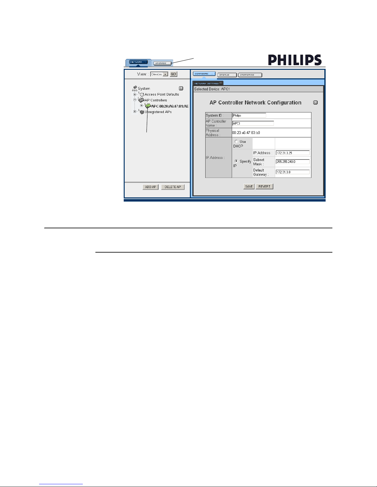
Newly Added
APC
Step 5. Add the APCs to the Network.
Not Used
Figure 3-4: APC Web Interface
Note The APCs will appear in the APC web interface with the System ID of Philips. Do not
modify this setting.
5. Select the APC in the View Device tree (selected device is displayed green) and
then select the Configure tab.
In the AP Controller Network Configuration screen, configure the following
parameters as necessary:
• System ID - Verify setting is Philips. If not, change it to Philips.
• AP Controller Name - Enter APC Name from APC worksheet (page 2-29).
• IP Addressing - Verify that the Specify IP radio button is marked and that the
IP Address, Subnet Mask and Default Gateway settings are as expected per
APC worksheet (page 2-29). If not, change the settings to match the
worksheet.
6. Click SAVE, and then verify the settings by selecting the Status tab.
7. At this time, add all other APCs to the network by repeating steps 1, 2, 3, 5, and
6 for each APC.
IntelliVue Telemetry System Infrastructure Installation and Service Guide 3-15
Page 94

Chapter 3: Installing and Configuring the ITS
Step 6. Run the Philips Upgrade Wizard.
Run the Philips Upgrade Wizard to check and verify the APCs you added to the
network are running the same version firmware. If any configuration modifications
are made, run the Philips Upgrade Wizard again.
The Philips Upgrade Wizard has been designed to automate and simplify the
upgrade process for ITS APC and APs. In addition to upgrading the firmware on
these ITS components, you can use the wizard to:
• verify that APCs on your network are configured correctly
• display warning and error messages that you may use to troubleshoot any
configuration errors that may exist on your ITS network
Compatibility
The Philips Upgrade Wizard requires supported, and compatible AP and APC
firmware. Note the compatibility requirements listed in Table 3-2.
Caution
Upgrade
Wizard Version
(A.00.16)
Release J
(A.00.08)
Release H
(A.00.07)
Release G
(A.00.0x)
Release F
Use of Versions A.00.08 and older of the Upgrade Wizard must be discontinued.
Table 3-1: Upgrade Wizard and APC/AP Compatibility
ITS Infrastructure Firmware Versions
Release J
2.4GHz
AP (B.00.08)
APC (B.00.18)
Compatible Compatible Compatible Compatible Compatible
Not Compatible
Warning: May
Cause AP Fault
Not Compatible
Warning: May
Cause AP Fault
Not Compatible
Warning: May
Cause AP Fault
Release J
1.4GHz Core
AP (A.00.19)
APC (B.00.18)
Not Compatible
Warning: May
Cause AP Fault
Not Compatible
Warning: May
Cause AP Fault
Not Compatible
Warning: May
Cause AP Fault
Release H
1.4GHz
AP (A.00.54)
APC (A.00.34)
Compatible Compatible Compatible
Not Compatible Compatible Compatible
Not Compatible Not Compatible Compatible
Release G
1.4GHz
AP (A.00.52)
APC (A.00.32)
Release F
1.4GHz
AP (A.00.50)
APC (A.00.29)
3-16
Page 95

Step 6. Run the Philips Upgrade Wizard.
Using the Upgrade Wizard
Caution Close the APC web interface before running the Philips Upgrade Wizard. Do not add
components to or remove components from the IntelliVue Telemetry System while
the wizard is running.
Follow these steps to upgrade ITS Access Point Controllers and Access Points using
the Philips Upgrade Wizard:
Philips Upgrade Wizard:
1. Run the Philips Upgrade Wizard by double-clicking the file:
C:\TelemetryUpgrader\upgrader.exe
The Upgrade Wizard splash screen (Figure 3-17) appears.
Figure 3-5: Upgrade Wizard Splash Screen
2. Click Next> to continue.
The APC/AP firmware selection screen (Figure 3-18) appears.
3. Complete the settings on the APC/AP firmware selection screen:
a) Click ... and then browse to the directory (e.g.,
and APC Images\)
in which you have installed the APC and AP firmware
C:\TelemetryUpgrader\AP
files.
b) Specify what type of APs you have installed by marking the appropriate radio
button, 1.4 GHz Smart Hopping or 2.4 GHz Smart Hopping.
Additionally, if you have installed Core APs, then be sure to mark the System
includes Cluster APs (with or without Remote Antennas) checkbox.
c) Verify that the correct firmware versions are displayed in the APC Version,
AP Version (Standard), and AP Version (Cluster) fields.
d) Select the ICN IP address (e.g., 172.31.240.4) you have configured for the
support PC on which you are running the wizard from the Use IP Address
drop-down menu. The menu lists the IP addresses of all Ethernet NICs
configured on the PC.
IntelliVue Telemetry System Infrastructure Installation and Service Guide 3-17
Page 96

Chapter 3: Installing and Configuring the ITS
Figure 3-6: APC/AP Firmware Selection Screen
e) Select Upgrade if necessary from the APC drop-down menu to allow each
APC to be upgraded. By default, an APC will not be upgraded if it is already
at the selected firmware version.
f) Select Smart Hopping-only Check and Update Configuration from the
unlabeled drop-down menu to verify and update the APC configuration.
g) Select Do Not Upgrade from the AP drop-down as you have only installed
APCs on the ITS at this point.
4. Click Next> to continue.
The wizard automatically scans the IntelliVue Telemetry System for all
connected APCs. When the scan is completed (Figure 3-19), the following
message appears:
System [Philips] – Master APC [e.g., APC-02*] Complete
* Note that the displayed APC value will be different for each clinical site.
After scanning the ITS for connected APCs, the Upgrade Wizard will list any APCs
that have an incompatible configuration key. If such an APC is found, you cannot
continue the upgrade process. Locate the incompatible APC, disconnect it from
the ITS, reset it to its factory defaults, and then reconnect it to the ITS before
retrying the upgrade process.
3-18
Page 97

Step 6. Run the Philips Upgrade Wizard.
Figure 3-7: APC Scan Completion Screen
5. Highlight/select the displayed message, e.g., System [Philips] – Master APC
[APC3E] Complete and then click Next> to continue.
The wizard scans the IntelliVue Telemetry System for all connected APs.
When the scan is completed, the following message appears:
Finished System scan
6. Click Next> to continue.
The APCs are queried, and a full navigational tree of the ITS is built and
displayed.
The tree lists the current firmware revision installed on each APC found in the
ITS.
Items needing an upgrade are shown in bold. If an AP needs an upgrade, the
APC it is connected to will also be shown in bold, even if that APC itself does not
require upgrading.
7. Select one APC (i.e., top level APC structure) at a time to upgrade. For example,
select APC [APC-C3] Version [A.00.29] and then select Next>.
The selected APC is taken offline, and the message Taking APC Offline is
displayed.
8. Click Next> to continue.
The APC upgrade process begins. The upgrade process may take several
minutes to complete. Status messages are displayed (Figure 3-20) as the
process runs.
IntelliVue Telemetry System Infrastructure Installation and Service Guide 3-19
Page 98

Chapter 3: Installing and Configuring the ITS
Figure 3-8: APC Upgrade Process Status Messages
The message Finished Upgrading APC appears when the upgrade process is
complete.
9. Click Next> to continue.
10. After all APCs have been upgraded, the Upgrade Wizard Report (Figure 3-21) is
displayed.
The report provides a summary of all devices upgraded along with any errors
that may have been generated during the upgrade process.
Click Save to save the report to a disk file (recommended).
Click Print to print the report without saving it.
Click Finish to close the Upgrade Wizard program.
3-20
Figure 3-9: Upgrade Wizard Report
Page 99

Step 7. Verify and Configure Important ITS Settings via the APC Interface.
Note that the Upgrade Wizard automatically creates a log file, logfile.txt, in the
directory from which it was run. Rename this log file and save it together with the
Upgrade Wizard Report disk file in another directory.
Step 7. Verify and Configure Important ITS Settings via the APC Interface.
After adding the remaining Access Point Controllers to the wireless subnet, several
important ITS settings must be verified and configured via the APC web interface to
ensure proper operation of the system. These include:
• Verify Filter Settings
• Verify BootP Address Ranges
• Configure the AP Defaults (for 1.4 GHz or 2.4 GHz APs)
• Configure AP Groups
• Configure Basic Settings for each Group
• Configure Alerts for each Group
Verifying the Filter Settings
To verify the network filter settings:
1. In View Device tree, select System and then select the Filters tab.
The Filter Configuration screen (Figure 3-10) appears.
2. Verify that the following network filter settings are configured as follows:
Protocol Type Filters:
• IP/ARP - UNCHECKED
• All others - CHECKED
Multicast Address Filter:
• Enable Multicast Filter - CHECKED
• Multicast Address - 01:00:5E:00:00:00
• Multicast Mask - ff:ff:ff:ff:ff:ff
ARP Filter:
• Enable ARP Filter - UNCHECKED
• Network IP Address - 0.0.0.0 (N/A)
- Network Subnet Mask - 0.0.0.0 (N/A)
IPX Broadcast Filters:
• All filters - CHECKED
• Broadcast Bandwidth Allocation - 20%
3. If you made any changes to the Network filter settings, click SAVE and then
verify the results.
IntelliVue Telemetry System Infrastructure Installation and Service Guide 3-21
Page 100

Chapter 3: Installing and Configuring the ITS
Figure 3-10: APC Filter Configuration Screen
3-22
 Loading...