

Page 1

IntelliVue Clinical Network
Installation and Service Manual
Part Number M3185-91909
Printed in the U.S.A. August 2003
Edition 1
Page 2

About this Manual
Proprietary Information
This document contains proprietary information, which is protected by copyright. All Rights
Reserved. Reproduction, adaptation, or translation without prior written permission is
prohibited, except as allowed under the copyright laws.
Philips Medical Systems
3000 Minuteman Road
Andover, MA 01810-1085
(978) 687-1501
Publication number
M3185-91909
Printed in USA
Warranty The information contained in this document is subject to change without notice.
Philips Medical Systems makes no warranty of any kind with regard to this material,
including, but not limited to, the implied warranties or merchantability and fitness for Philips
Medical Systems shall not be liable for errors contained herein or for incidental or
consequential damages in connection with the furnishing, performance, or use of this material.
Copyright Copyright © 2003 Philips Electronics North America Corporation
Windows NT, Windows 98, and Windows 2000 are registered Trademarks of Microsoft
Corporation.
Printing History
2
New editions of this document incorporate all material updated since the previous edition.
Update packages may be issued between editions and contain replacement and additional
pages to be merged by a revision date at the bottom of the page. Pages that are rearranged due
to changes on a previous page are not considered revised.
The documentation printing date and part number indicate its current edition. The printing
date changes when a new edition is printed. (Minor corrections and updates that are
incorporated at reprint do not cause the date to change.) The document part number changes
when extensive technical changes are incorporated.
First Edition............................................................... August 2003
IntelliVue Clinical Network Release E.01.xx
Page 3
Text
The following conventions for Notes, Cautions, and Warnings are used in this manual.
Conventions
Note A Note calls attention to an important point in the text.
Caution A Caution calls attention to a condition or possible situation that could damage or
destroy the product or the user’s work.
Warning A Warning calls attention to a condition or possible situation that could cause injury to
the user and/or patient.
Explanation of Symbols
Symbols on products and packaging mean the following:
Defibrillator-proof type CF equipment
Caution: Consult accompanying documents.
Signal (ECG) Input
Signal (ECG) Output
Data input/output
Alternating Current
Direct Current
Protective earth
3
Page 4
Equipotential grounding post
Temperature
Humidity
Altitude or atmospheric pressure
Contains parts to be recycled
Contains parts that may not be put into normal waste disposal but must be recycled
or dealt with as chemical waste
Fragile, handle with care
Keep dry
Consult instructions for use
Date of manufacture
Serial number
Catalog number
Batch code
4
Page 5

About this Document
This document contains Service and Installation information for the IntelliVue Clinical
Network, (hereinafter called the Clinical Network). Other products referenced are the
IntelliVue Information Center, IntelliVue Information Center Client, IntelliVue Database
Server, IntelliVue Small Database Server, and the IntelliVue Application Server.
Documentation CD
The Service and User Documentation CD contains the following IntelliVue
documentation:
• Clinical Network Installation and Service Manual
• Database Server Installation and Service Manual
• Information Center Installation and Service Manual
• Information Center Instructions for Use
• Information Center Installation Notes
• Information Center, Clinical Network, and Database Server Quick Reference Guides
• Application Notes
• Service Documentation for the PC Workstation, NetServer, LaserJet Printer, and other
hardware devices
5
Page 6

6
Page 7

Table of Contents
About this Manual. . . . . . . . . . . . . . . . . . . . . . . . . . . . . . . . . . . . . . . . . . . . . . . . . . . . .1-2
Proprietary Information. . . . . . . . . . . . . . . . . . . . . . . . . . . . . . . . . . . . . . . . . . . . . . .1-2
Warranty. . . . . . . . . . . . . . . . . . . . . . . . . . . . . . . . . . . . . . . . . . . . . . . . . . . . . . . . . .1-2
Copyright . . . . . . . . . . . . . . . . . . . . . . . . . . . . . . . . . . . . . . . . . . . . . . . . . . . . . . . . .1-2
Printing History . . . . . . . . . . . . . . . . . . . . . . . . . . . . . . . . . . . . . . . . . . . . . . . . . . . . .1-2
Text Conventions . . . . . . . . . . . . . . . . . . . . . . . . . . . . . . . . . . . . . . . . . . . . . . . . . . .1-3
Explanation of Symbols . . . . . . . . . . . . . . . . . . . . . . . . . . . . . . . . . . . . . . . . . . . . . .1-3
About this Document . . . . . . . . . . . . . . . . . . . . . . . . . . . . . . . . . . . . . . . . . . . . . . . . . .1-5
Document-ation CD . . . . . . . . . . . . . . . . . . . . . . . . . . . . . . . . . . . . . . . . . . . . . . . . .1-5
Introduction. . . . . . . . . . . . . . . . . . . . . . . . . . . . . . . . . . . . . . . . . . . . . . . . .1-1
Overview . . . . . . . . . . . . . . . . . . . . . . . . . . . . . . . . . . . . . . . . . . . . . . . . . . . . . . . . . . . .1-1
Philips Patient Care System . . . . . . . . . . . . . . . . . . . . . . . . . . . . . . . . . . . . . . . . . . . .1-2
Patient Monitors . . . . . . . . . . . . . . . . . . . . . . . . . . . . . . . . . . . . . . . . . . . . . . . . . . . .1-2
Clinical Network Connected Operation . . . . . . . . . . . . . . . . . . . . . . . . . . . . . . 1-3
Information Center Client . . . . . . . . . . . . . . . . . . . . . . . . . . . . . . . . . . . . . . . . 1-3
Networks . . . . . . . . . . . . . . . . . . . . . . . . . . . . . . . . . . . . . . . . . . . . . . . . . . . . . . . . .1-4
Philips CareNet . . . . . . . . . . . . . . . . . . . . . . . . . . . . . . . . . . . . . . . . . . . . . . . . 1-4
Clinical Network . . . . . . . . . . . . . . . . . . . . . . . . . . . . . . . . . . . . . . . . . . . . . . . . 1-5
Patient Care Systems. . . . . . . . . . . . . . . . . . . . . . . . . . . . . . . . . . . . . . . . . . . . . . . .1-7
Clinical Network Without a Database Server . . . . . . . . . . . . . . . . . . . . . . . . . . 1-7
Clinical Network With
IntelliVue Database Server . . . . . . . . . . . . . . . . . . . . . . . . . . . . . . . . . . . . . . . 1-7
Clinical Network With
IntelliVue Small Database Server . . . . . . . . . . . . . . . . . . . . . . . . . . . . . . . . . . 1-9
M3185 Clinical Network . . . . . . . . . . . . . . . . . . . . . . . . . . . . . . . . . . . . . . . . . . . . . .1-9
Switches . . . . . . . . . . . . . . . . . . . . . . . . . . . . . . . . . . . . . . . . . . . . . . . . . . . . . 1-9
Network Connections. . . . . . . . . . . . . . . . . . . . . . . . . . . . . . . . . . . . . . . . . . . 1-10
Extended Distances. . . . . . . . . . . . . . . . . . . . . . . . . . . . . . . . . . . . . . . . . . . . 1-10
Components and Options . . . . . . . . . . . . . . . . . . . . . . . . . . . . . . . . . . . . . . . . . . . . .1-12
Contents 1
Page 8

Active Components . . . . . . . . . . . . . . . . . . . . . . . . . . . . . . . . . . . . . . . . . . . . . . . . 1-12
Purchased Options . . . . . . . . . . . . . . . . . . . . . . . . . . . . . . . . . . . . . . . . . . . . . . . . 1-12
Cabling Installation Materials. . . . . . . . . . . . . . . . . . . . . . . . . . . . . . . . . . . . . . . . . 1-12
Mounting Options . . . . . . . . . . . . . . . . . . . . . . . . . . . . . . . . . . . . . . . . . . . . . . . . . 1-13
Hardware Description. . . . . . . . . . . . . . . . . . . . . . . . . . . . . . . . . . . . . . . . .2-1
Overview . . . . . . . . . . . . . . . . . . . . . . . . . . . . . . . . . . . . . . . . . . . . . . . . . . . . . . . . . . . . 2-1
System Components . . . . . . . . . . . . . . . . . . . . . . . . . . . . . . . . . . . . . . . . . . . . . . . . . . 2-2
Core/Edge Switches . . . . . . . . . . . . . . . . . . . . . . . . . . . . . . . . . . . . . . . . . . . . . . . . 2-3
Extension Switch/Repeater . . . . . . . . . . . . . . . . . . . . . . . . . . . . . . . . . . . . . . . . . . . 2-4
Wireless Access Points . . . . . . . . . . . . . . . . . . . . . . . . . . . . . . . . . . . . . . . . . . . . . . 2-5
Access Points Mount Kit . . . . . . . . . . . . . . . . . . . . . . . . . . . . . . . . . . . . . . . . 2-6
Access Point Controller . . . . . . . . . . . . . . . . . . . . . . . . . . . . . . . . . . . . . . . . . . . . . . 2-7
Remote Power System . . . . . . . . . . . . . . . . . . . . . . . . . . . . . . . . . . . . . . . . . . . . . . 2-8
AP Power Over LAN . . . . . . . . . . . . . . . . . . . . . . . . . . . . . . . . . . . . . . . . . . . . . . . . 2-9
Wireless Bedside Adapter . . . . . . . . . . . . . . . . . . . . . . . . . . . . . . . . . . . . . . . . . . . 2-10
Media Translators . . . . . . . . . . . . . . . . . . . . . . . . . . . . . . . . . . . . . . . . . . . . . . . . . 2-11
Printer . . . . . . . . . . . . . . . . . . . . . . . . . . . . . . . . . . . . . . . . . . . . . . . . . . . . . . . . . . 2-14
Uninterruptible Power Supply . . . . . . . . . . . . . . . . . . . . . . . . . . . . . . . . . . . . . . . . 2-15
Operation . . . . . . . . . . . . . . . . . . . . . . . . . . . . . . . . . . . . . . . . . . . . . . . . . . . 2-16
M3185 Cables and Installation Materials. . . . . . . . . . . . . . . . . . . . . . . . . . . . . . . . 2-17
UTP Cable. . . . . . . . . . . . . . . . . . . . . . . . . . . . . . . . . . . . . . . . . . . . . . . . . . . 2-17
Fiber Optic Cable . . . . . . . . . . . . . . . . . . . . . . . . . . . . . . . . . . . . . . . . . . . . . 2-19
Wall Boxes . . . . . . . . . . . . . . . . . . . . . . . . . . . . . . . . . . . . . . . . . . . . . . . . . . 2-20
Patch Panels . . . . . . . . . . . . . . . . . . . . . . . . . . . . . . . . . . . . . . . . . . . . . . . . . 2-21
Specifications. . . . . . . . . . . . . . . . . . . . . . . . . . . . . . . . . . . . . . . . . . . . . . . . . . . . . . . 2-22
Physical . . . . . . . . . . . . . . . . . . . . . . . . . . . . . . . . . . . . . . . . . . . . . . . . . . . . . . . . . 2-23
Environmental . . . . . . . . . . . . . . . . . . . . . . . . . . . . . . . . . . . . . . . . . . . . . . . . . . . . 2-24
Electrical . . . . . . . . . . . . . . . . . . . . . . . . . . . . . . . . . . . . . . . . . . . . . . . . . . . . . . . . 2-25
Regulatory . . . . . . . . . . . . . . . . . . . . . . . . . . . . . . . . . . . . . . . . . . . . . . . . . . . . . . . . . 2-26
Philips Software. . . . . . . . . . . . . . . . . . . . . . . . . . . . . . . . . . . . . . . . . . . . . . . . . . . 2-26
Philips Hardware . . . . . . . . . . . . . . . . . . . . . . . . . . . . . . . . . . . . . . . . . . . . . . . . . . 2-26
Contents 2
Page 9

Site Planning . . . . . . . . . . . . . . . . . . . . . . . . . . . . . . . . . . . . . . . . . . . . . . . 3-1
Overview. . . . . . . . . . . . . . . . . . . . . . . . . . . . . . . . . . . . . . . . . . . . . . . . . . . . . . . . . . . . 3-1
Site Planning . . . . . . . . . . . . . . . . . . . . . . . . . . . . . . . . . . . . . . . . . . . . . . . . . . . . . . . . 3-2
Considerations . . . . . . . . . . . . . . . . . . . . . . . . . . . . . . . . . . . . . . . . . . . . . . . . . . . . 3-2
Responsibilities. . . . . . . . . . . . . . . . . . . . . . . . . . . . . . . . . . . . . . . . . . . . . . . . . 3-2
Customer . . . . . . . . . . . . . . . . . . . . . . . . . . . . . . . . . . . . . . . . . . . . . . . . . . . . . 3-2
Philips Factory . . . . . . . . . . . . . . . . . . . . . . . . . . . . . . . . . . . . . . . . . . . . . . . . . 3-3
Philips Service Provider . . . . . . . . . . . . . . . . . . . . . . . . . . . . . . . . . . . . . . . . . . 3-3
Location. . . . . . . . . . . . . . . . . . . . . . . . . . . . . . . . . . . . . . . . . . . . . . . . . . . . . . . . . . 3-3
Wiring Closets . . . . . . . . . . . . . . . . . . . . . . . . . . . . . . . . . . . . . . . . . . . . . . . . . 3-4
Rack Mounting . . . . . . . . . . . . . . . . . . . . . . . . . . . . . . . . . . . . . . . . . . . . . . . . . 3-4
Switches . . . . . . . . . . . . . . . . . . . . . . . . . . . . . . . . . . . . . . . . . . . . . . . . . . . . . . 3-4
Wireless Access Points . . . . . . . . . . . . . . . . . . . . . . . . . . . . . . . . . . . . . . . . . . 3-4
Extension Switches & Media Translators . . . . . . . . . . . . . . . . . . . . . . . . . . . . . 3-4
UPSs . . . . . . . . . . . . . . . . . . . . . . . . . . . . . . . . . . . . . . . . . . . . . . . . . . . . . . . . 3-5
Other. . . . . . . . . . . . . . . . . . . . . . . . . . . . . . . . . . . . . . . . . . . . . . . . . . . . . . . . . 3-5
Network . . . . . . . . . . . . . . . . . . . . . . . . . . . . . . . . . . . . . . . . . . . . . . . . . . . . . . . . . . 3-5
Cabling . . . . . . . . . . . . . . . . . . . . . . . . . . . . . . . . . . . . . . . . . . . . . . . . . . . . . . . . . . 3-5
Environmental Requirements . . . . . . . . . . . . . . . . . . . . . . . . . . . . . . . . . . . . . . . . . 3-6
Electrical Requirements . . . . . . . . . . . . . . . . . . . . . . . . . . . . . . . . . . . . . . . . . . . . . 3-6
Equipment Mounting . . . . . . . . . . . . . . . . . . . . . . . . . . . . . . . . . . . . . . . . . . . . . . . . 3-6
Safety . . . . . . . . . . . . . . . . . . . . . . . . . . . . . . . . . . . . . . . . . . . . . . . . . . . . . . . . . . . 3-6
Medical Device Standards . . . . . . . . . . . . . . . . . . . . . . . . . . . . . . . . . . . . . . . . 3-6
Philips Device Requirements . . . . . . . . . . . . . . . . . . . . . . . . . . . . . . . . . . . . . . 3-6
Patient Environment . . . . . . . . . . . . . . . . . . . . . . . . . . . . . . . . . . . . . . . . . . . . . 3-6
Network Design . . . . . . . . . . . . . . . . . . . . . . . . . . . . . . . . . . . . . . . . . . . . . . . . . . . . . . 3-7
Clinical Requirements . . . . . . . . . . . . . . . . . . . . . . . . . . . . . . . . . . . . . . . . . . . . . . . 3-7
Number of Units and Beds . . . . . . . . . . . . . . . . . . . . . . . . . . . . . . . . . . . . . . . . 3-7
Patient Monitor Type. . . . . . . . . . . . . . . . . . . . . . . . . . . . . . . . . . . . . . . . . . . . . 3-7
Central Monitoring Locations . . . . . . . . . . . . . . . . . . . . . . . . . . . . . . . . . . . . . . 3-7
Patient Data Review Locations. . . . . . . . . . . . . . . . . . . . . . . . . . . . . . . . . . . . . 3-7
Type of Patient Data Access . . . . . . . . . . . . . . . . . . . . . . . . . . . . . . . . . . . . . . 3-8
Future Capability . . . . . . . . . . . . . . . . . . . . . . . . . . . . . . . . . . . . . . . . . . . . . . . 3-8
Philips Hardware Capability . . . . . . . . . . . . . . . . . . . . . . . . . . . . . . . . . . . . . . . . . . 3-8
Patient Monitors . . . . . . . . . . . . . . . . . . . . . . . . . . . . . . . . . . . . . . . . . . . . . . . . 3-9
Contents 3
Page 10

CareNet. . . . . . . . . . . . . . . . . . . . . . . . . . . . . . . . . . . . . . . . . . . . . . . . . . . . . . 3-9
Clinical Network . . . . . . . . . . . . . . . . . . . . . . . . . . . . . . . . . . . . . . . . . . . . . . . 3-9
Printers . . . . . . . . . . . . . . . . . . . . . . . . . . . . . . . . . . . . . . . . . . . . . . . . . . . . . 3-10
Switch Function. . . . . . . . . . . . . . . . . . . . . . . . . . . . . . . . . . . . . . . . . . . . . . . 3-10
Switch Firmware . . . . . . . . . . . . . . . . . . . . . . . . . . . . . . . . . . . . . . . . . . . . . . 3-10
Switch Rules . . . . . . . . . . . . . . . . . . . . . . . . . . . . . . . . . . . . . . . . . . . . . . . . . 3-10
Upgraded Systems . . . . . . . . . . . . . . . . . . . . . . . . . . . . . . . . . . . . . . . . . . . . . 3-11
Designing Clinical Network Systems . . . . . . . . . . . . . . . . . . . . . . . . . . . . . . . . . . . 3-11
Connecting Devices . . . . . . . . . . . . . . . . . . . . . . . . . . . . . . . . . . . . . . . . . . . 3-12
Specific Network Device Settings . . . . . . . . . . . . . . . . . . . . . . . . . . . . . . . . . 3-13
Drawing the Design. . . . . . . . . . . . . . . . . . . . . . . . . . . . . . . . . . . . . . . . . . . . 3-13
Design Guidelines . . . . . . . . . . . . . . . . . . . . . . . . . . . . . . . . . . . . . . . . . . . . . . . . . 3-13
Directed Messages . . . . . . . . . . . . . . . . . . . . . . . . . . . . . . . . . . . . . . . . . . . . 3-14
Broadcast and Multicast Messages . . . . . . . . . . . . . . . . . . . . . . . . . . . . . . . 3-14
Example 1: Single Switch Network . . . . . . . . . . . . . . . . . . . . . . . . . . . . . . . . 3-14
Example 2: Multiple Switch Network . . . . . . . . . . . . . . . . . . . . . . . . . . . . . . . 3-16
Wireless Network Systems . . . . . . . . . . . . . . . . . . . . . . . . . . . . . . . . . . . . . . . . . . . . 3-19
Frequency Management . . . . . . . . . . . . . . . . . . . . . . . . . . . . . . . . . . . . . . . . . . . . 3-19
Wireless Network Design Guidelines . . . . . . . . . . . . . . . . . . . . . . . . . . . . . . . . . . 3-19
Standard vs Non-Standard Systems . . . . . . . . . . . . . . . . . . . . . . . . . . . . . . . . . . . 3-20
Standard System Design. . . . . . . . . . . . . . . . . . . . . . . . . . . . . . . . . . . . . . . . . . . . 3-21
Standard System Example . . . . . . . . . . . . . . . . . . . . . . . . . . . . . . . . . . . . . . 3-22
Non-Standard System Design . . . . . . . . . . . . . . . . . . . . . . . . . . . . . . . . . . . . . . . . 3-25
Non-Standard System Example . . . . . . . . . . . . . . . . . . . . . . . . . . . . . . . . . . 3-25
Channel Reuse-Example . . . . . . . . . . . . . . . . . . . . . . . . . . . . . . . . . . . . . . . 3-26
RF Survey . . . . . . . . . . . . . . . . . . . . . . . . . . . . . . . . . . . . . . . . . . . . . . . . . . . . . . . 3-27
Performing the RF Data Throughput Survey. . . . . . . . . . . . . . . . . . . . . . . . . 3-27
Checking for Channel Reuse . . . . . . . . . . . . . . . . . . . . . . . . . . . . . . . . . . . . 3-30
Installing the Clinical Network. . . . . . . . . . . . . . . . . . . . . . . . . . . . . . . . . .4-1
Overview . . . . . . . . . . . . . . . . . . . . . . . . . . . . . . . . . . . . . . . . . . . . . . . . . . . . . . . . . . . . 4-1
Preparing for Installation . . . . . . . . . . . . . . . . . . . . . . . . . . . . . . . . . . . . . . . . . . . . . . 4-2
Cable Plant Installation . . . . . . . . . . . . . . . . . . . . . . . . . . . . . . . . . . . . . . . . . . . . . . 4-2
Installation Materials . . . . . . . . . . . . . . . . . . . . . . . . . . . . . . . . . . . . . . . . . . . . 4-2
Noise Immunity . . . . . . . . . . . . . . . . . . . . . . . . . . . . . . . . . . . . . . . . . . . . . . . . 4-2
Contents 4
Page 11

UTP Cable Plant Installation. . . . . . . . . . . . . . . . . . . . . . . . . . . . . . . . . . . . . . . 4-3
RJ-45 Connections . . . . . . . . . . . . . . . . . . . . . . . . . . . . . . . . . . . . . . . . . . . . . . 4-4
Fiber Optic Cable Plant Installation . . . . . . . . . . . . . . . . . . . . . . . . . . . . . . . . . 4-4
Unpacking and Inspection. . . . . . . . . . . . . . . . . . . . . . . . . . . . . . . . . . . . . . . . . . . . 4-4
Philips Shipments . . . . . . . . . . . . . . . . . . . . . . . . . . . . . . . . . . . . . . . . . . . . . . . 4-4
Unpacking Components . . . . . . . . . . . . . . . . . . . . . . . . . . . . . . . . . . . . . . . . . . 4-5
Checking Inventory. . . . . . . . . . . . . . . . . . . . . . . . . . . . . . . . . . . . . . . . . . . . . . 4-5
Inspection . . . . . . . . . . . . . . . . . . . . . . . . . . . . . . . . . . . . . . . . . . . . . . . . . . . . . . . . 4-5
Packaging Inspection . . . . . . . . . . . . . . . . . . . . . . . . . . . . . . . . . . . . . . . . . . . . 4-5
Mechanical Inspection . . . . . . . . . . . . . . . . . . . . . . . . . . . . . . . . . . . . . . . . . . . 4-5
Electrical Inspection . . . . . . . . . . . . . . . . . . . . . . . . . . . . . . . . . . . . . . . . . . . . . 4-6
Claims for Damage. . . . . . . . . . . . . . . . . . . . . . . . . . . . . . . . . . . . . . . . . . . . . . 4-6
Re-packaging for Shipment . . . . . . . . . . . . . . . . . . . . . . . . . . . . . . . . . . . . . . . 4-6
Network Component Installation . . . . . . . . . . . . . . . . . . . . . . . . . . . . . . . . . . . . . . . . 4-7
Switch Firmware . . . . . . . . . . . . . . . . . . . . . . . . . . . . . . . . . . . . . . . . . . . . . . . . . . . 4-7
Device Configuration. . . . . . . . . . . . . . . . . . . . . . . . . . . . . . . . . . . . . . . . . . . . . . . . 4-7
Using ConfigTool . . . . . . . . . . . . . . . . . . . . . . . . . . . . . . . . . . . . . . . . . . . . . . . 4-8
Network Switches . . . . . . . . . . . . . . . . . . . . . . . . . . . . . . . . . . . . . . . . . . . . . . 4-11
RangeLAN2 Access Points . . . . . . . . . . . . . . . . . . . . . . . . . . . . . . . . . . . . . . 4-14
M3/M4 Monitors . . . . . . . . . . . . . . . . . . . . . . . . . . . . . . . . . . . . . . . . . . . . . . . 4-16
Wireless Bedside Adapters . . . . . . . . . . . . . . . . . . . . . . . . . . . . . . . . . . . . . . . . . . 4-19
Access Point Controllers & Harmony Access Points . . . . . . . . . . . . . . . . . . . . . . 4-21
Configuration Troubleshooting . . . . . . . . . . . . . . . . . . . . . . . . . . . . . . . . . . . . 4-28
Using HyperTerminal Connection . . . . . . . . . . . . . . . . . . . . . . . . . . . . . . . . . . 4-29
Physical Installation. . . . . . . . . . . . . . . . . . . . . . . . . . . . . . . . . . . . . . . . . . . . . . . . 4-42
Switches . . . . . . . . . . . . . . . . . . . . . . . . . . . . . . . . . . . . . . . . . . . . . . . . . . . . . 4-42
RangeLAN2 Wireless Access Points . . . . . . . . . . . . . . . . . . . . . . . . . . . . . . . 4-42
Media Translators. . . . . . . . . . . . . . . . . . . . . . . . . . . . . . . . . . . . . . . . . . . . . . 4-44
Network Connections . . . . . . . . . . . . . . . . . . . . . . . . . . . . . . . . . . . . . . . . . . . . . . 4-45
Switch to Switch . . . . . . . . . . . . . . . . . . . . . . . . . . . . . . . . . . . . . . . . . . . . . . . 4-48
Switch to 100 Mbps HALF Network Devices . . . . . . . . . . . . . . . . . . . . . . . . . 4-48
Switch to 100 Mbps FULL Network Devices. . . . . . . . . . . . . . . . . . . . . . . . . . 4-48
Switch to 10 Mbps Network Devices . . . . . . . . . . . . . . . . . . . . . . . . . . . . . . . 4-49
Clinical Network Devices: Names and IP Addresses . . . . . . . . . . . . . . . . . . . . . . . 4-50
IP Address. . . . . . . . . . . . . . . . . . . . . . . . . . . . . . . . . . . . . . . . . . . . . . . . . . . . . . . 4-50
Subnet Mask . . . . . . . . . . . . . . . . . . . . . . . . . . . . . . . . . . . . . . . . . . . . . . . . . . . . . 4-51
Contents 5
Page 12

Default Gateway . . . . . . . . . . . . . . . . . . . . . . . . . . . . . . . . . . . . . . . . . . . . . . . . . . 4-51
MAC Address . . . . . . . . . . . . . . . . . . . . . . . . . . . . . . . . . . . . . . . . . . . . . . . . . . . . 4-51
Host Name. . . . . . . . . . . . . . . . . . . . . . . . . . . . . . . . . . . . . . . . . . . . . . . . . . . . . . . 4-51
Device Name . . . . . . . . . . . . . . . . . . . . . . . . . . . . . . . . . . . . . . . . . . . . . . . . . . . . . 4-52
Setting Host Names and IP Addresses . . . . . . . . . . . . . . . . . . . . . . . . . . . . . . . . . 4-52
Verifying Network Connectivity . . . . . . . . . . . . . . . . . . . . . . . . . . . . . . . . . . . . . . . 4-52
Troubleshooting the Clinical Network . . . . . . . . . . . . . . . . . . . . . . . . . . .5-1
Overview . . . . . . . . . . . . . . . . . . . . . . . . . . . . . . . . . . . . . . . . . . . . . . . . . . . . . . . . . . . . 5-1
Maintenance . . . . . . . . . . . . . . . . . . . . . . . . . . . . . . . . . . . . . . . . . . . . . . . . . . . . . . . . . 5-2
Routine Maintenance. . . . . . . . . . . . . . . . . . . . . . . . . . . . . . . . . . . . . . . . . . . . . . . . 5-2
Air Intakes . . . . . . . . . . . . . . . . . . . . . . . . . . . . . . . . . . . . . . . . . . . . . . . . . . . . 5-2
UPS. . . . . . . . . . . . . . . . . . . . . . . . . . . . . . . . . . . . . . . . . . . . . . . . . . . . . . . . . 5-2
Troubleshooting. . . . . . . . . . . . . . . . . . . . . . . . . . . . . . . . . . . . . . . . . . . . . . . . . . . . . . 5-4
Troubleshooting Strategy . . . . . . . . . . . . . . . . . . . . . . . . . . . . . . . . . . . . . . . . . . . . 5-5
SDN Connectivity . . . . . . . . . . . . . . . . . . . . . . . . . . . . . . . . . . . . . . . . . . . . . . 5-6
Wireless Connectivity . . . . . . . . . . . . . . . . . . . . . . . . . . . . . . . . . . . . . . . . . . . 5-6
. . . . . . . . . . . . . . . . . . . . . . . . . . . . . . . . . . . . . . . . . . . . . . . . . . . . . . . . . . . . 5-7
Network Connectivity . . . . . . . . . . . . . . . . . . . . . . . . . . . . . . . . . . . . . . . . . . . 5-8
Server Connectivity . . . . . . . . . . . . . . . . . . . . . . . . . . . . . . . . . . . . . . . . . . . . . 5-9
System Trouble-shooting. . . . . . . . . . . . . . . . . . . . . . . . . . . . . . . . . . . . . . . . . . . . 5-10
Network Statistics . . . . . . . . . . . . . . . . . . . . . . . . . . . . . . . . . . . . . . . . . . . . . . . . . . . 5-13
Switches . . . . . . . . . . . . . . . . . . . . . . . . . . . . . . . . . . . . . . . . . . . . . . . . . . . . . . . . 5-13
HP 2524 Switch. . . . . . . . . . . . . . . . . . . . . . . . . . . . . . . . . . . . . . . . . . . . . . . 5-13
Cisco 1900 Switch . . . . . . . . . . . . . . . . . . . . . . . . . . . . . . . . . . . . . . . . . . . . 5-20
Access Points . . . . . . . . . . . . . . . . . . . . . . . . . . . . . . . . . . . . . . . . . . . . . . . . . . . . 5-22
Diagnostics. . . . . . . . . . . . . . . . . . . . . . . . . . . . . . . . . . . . . . . . . . . . . . . . . . . . . . . . . 5-26
Service Portal Support. . . . . . . . . . . . . . . . . . . . . . . . . . . . . . . . . . . . . . . . . . . . . . 5-26
LED Diagnostics . . . . . . . . . . . . . . . . . . . . . . . . . . . . . . . . . . . . . . . . . . . . . . . . . . . . 5-28
LAN Interface Card . . . . . . . . . . . . . . . . . . . . . . . . . . . . . . . . . . . . . . . . . . . . . . . . 5-28
Harmony Access Point LED Diagnostics. . . . . . . . . . . . . . . . . . . . . . . . . . . . . . . . 5-29
RangeLAN2 Access Point . . . . . . . . . . . . . . . . . . . . . . . . . . . . . . . . . . . . . . . . . . . 5-30
Contents 6
Page 13

Access Point Controller LED Diagnostics . . . . . . . . . . . . . . . . . . . . . . . . . . . . . . . 5-32
Remote Power System LED Diagnostics . . . . . . . . . . . . . . . . . . . . . . . . . . . . . . . 5-33
HP2524 Switch . . . . . . . . . . . . . . . . . . . . . . . . . . . . . . . . . . . . . . . . . . . . . . . . . . . 5-33
Cisco Switch . . . . . . . . . . . . . . . . . . . . . . . . . . . . . . . . . . . . . . . . . . . . . . . . . . . . . 5-35
Allied Telesyn AT-FS708 switch . . . . . . . . . . . . . . . . . . . . . . . . . . . . . . . . . . . . . . 5-36
LED Status Indicators. . . . . . . . . . . . . . . . . . . . . . . . . . . . . . . . . . . . . . . . . . . 5-36
Ports 1 - 7
LED Status Indications . . . . . . . . . . . . . . . . . . . . . . . . . . . . . . . . . . . . . . . . . . 5-37
Port 8MDI
LED Status Indications . . . . . . . . . . . . . . . . . . . . . . . . . . . . . . . . . . . . . . . . . . 5-37
J3300 10Base-T Hub . . . . . . . . . . . . . . . . . . . . . . . . . . . . . . . . . . . . . . . . . . . . . . 5-38
10 Mbps Media Translator . . . . . . . . . . . . . . . . . . . . . . . . . . . . . . . . . . . . . . . . . . 5-39
100 Mbps Media Translator . . . . . . . . . . . . . . . . . . . . . . . . . . . . . . . . . . . . . . . . . 5-40
Repair . . . . . . . . . . . . . . . . . . . . . . . . . . . . . . . . . . . . . . . . . . . . . . . . . . . . . . . . . . . . . 5-42
Philips Hardware . . . . . . . . . . . . . . . . . . . . . . . . . . . . . . . . . . . . . . . . . . . . . . . . . . 5-42
UPS . . . . . . . . . . . . . . . . . . . . . . . . . . . . . . . . . . . . . . . . . . . . . . . . . . . . . . . . 5-42
UPS Configuration . . . . . . . . . . . . . . . . . . . . . . . . . . . . . . . . . . . . . . . . . . . . . 5-44
Restoring Switch Firmware - HP2524 . . . . . . . . . . . . . . . . . . . . . . . . . . . . . . 5-46
Single Switch Firmware restore . . . . . . . . . . . . . . . . . . . . . . . . . . . . . . . . . . . 5-46
Switch to Switch Firmware Restore . . . . . . . . . . . . . . . . . . . . . . . . . . . . . . . . 5-49
Restoring Switch Firmware - Cisco . . . . . . . . . . . . . . . . . . . . . . . . . . . . . . . . 5-53
Restoring Wireless M3/M4 Wireless Adapter Firmware . . . . . . . . . . . . . . . . . 5-59
Restoring Access Point Firmware . . . . . . . . . . . . . . . . . . . . . . . . . . . . . . . . . 5-65
Replaceable Parts. . . . . . . . . . . . . . . . . . . . . . . . . . . . . . . . . . . . . . . . . . . . . . . . . 5-71
Testing Product Assurance . . . . . . . . . . . . . . . . . . . . . . . . . . . . . . . . . . . 6-1
Testing Product Assurance . . . . . . . . . . . . . . . . . . . . . . . . . . . . . . . . . . . . . . . . . . . . 6-1
Visual Tests. . . . . . . . . . . . . . . . . . . . . . . . . . . . . . . . . . . . . . . . . . . . . . . . . . . . . . . 6-1
System Components . . . . . . . . . . . . . . . . . . . . . . . . . . . . . . . . . . . . . . . . . . . . 6-1
Cables . . . . . . . . . . . . . . . . . . . . . . . . . . . . . . . . . . . . . . . . . . . . . . . . . . . . . . . 6-1
Connectors . . . . . . . . . . . . . . . . . . . . . . . . . . . . . . . . . . . . . . . . . . . . . . . . . . . . 6-1
Test and Inspection Procedures . . . . . . . . . . . . . . . . . . . . . . . . . . . . . . . . . . . . . . . 6-1
Clinical Network . . . . . . . . . . . . . . . . . . . . . . . . . . . . . . . . . . . . . . . . . . . . . . . . 6-3
Worksheets . . . . . . . . . . . . . . . . . . . . . . . . . . . . . . . . . . . . . . . . . . . . . . . . A-1
Contents 7
Page 14

Overview . . . . . . . . . . . . . . . . . . . . . . . . . . . . . . . . . . . . . . . . . . . . . . . . . . . . . . . . . . . .A-1
Network Installation . . . . . . . . . . . . . . . . . . . . . . . . . . . . . . . . . . . . . . . . . . . . . . . . . . . A-2
Remote Clients on T1 Lines. . . . . . . . . . . . . . . . . . . . . . . . . . . . . . . . . . . B-1
Overview . . . . . . . . . . . . . . . . . . . . . . . . . . . . . . . . . . . . . . . . . . . . . . . . . . . . . . . . . . . .B-1
System Diagrams. . . . . . . . . . . . . . . . . . . . . . . . . . . . . . . . . . . . . . . . . . . . . . . . . . . . .B-2
Changing Network Properties . . . . . . . . . . . . . . . . . . . . . . . . . . . . . . . . . . . . . . . . . B-4
Contents 8
Page 15

1
Introduction
Overview
The IntelliVue Clinical Network is the Philips Medical Systems medical network for
transmitting and reviewing patient monitoring data from multiple IntelliVue Information
Center central monitors within and across units in a clinical care environment. It is based on
industry standard components and cabling and provides for interconnecting up to 8
Information Centers at different clinical locations.
Note The Information Center Installation and Service Manual provides detailed information
on the Information Center, Information Center Client, and the Database Servers.
Note The Application Server Installation and Service Manual provides detailed information
on the Application Server.
Chapter 1 overviews the Clinical Network in the following sections.
Philips Patient Care System . . . . . . . . . . . . . . . . . . . . . page 1-2
Components and Options . . . . . . . . . . . . . . . . . . . . . . . page 1-12
Introduction 1-1
Page 16

Philips Patient Care System
Philips Patient Care System
The Philips Patient Care System provides a comprehensive patient monitoring solution for a
variety of clinical environments -- ER, ICU, CCU, Stepdown Unit. It comprises patient
monitors for obtaining patient monitoring data, central monitors for displaying and analyzing
patient monitoring data, and switches and networks for interconnecting components at
multiple hospital locations.
Patient monitors can be Philips hardwired CMS, 24 Monitors, telemetry monitors, IntelliVue
Patient Monitors, or M3/M4 monitors (hardwired or wireless). Central monitors are the
IntelliVue Information Centers. The switch and network can be the Philips CareNet with
CareNet switch or the IntelliVue Clinical Network that uses industry standard network
components. The database server is the IntelliVue Database Server or the IntelliVue Small
Database Server.
Patient Monitors
Patient monitors from Philips Medical Systems provide a wide variety of patient monitoring
solutions with the Clinical Network. Compatible patient monitors that connect directly to the
Clinical Network (wired and/or wireless) are the family of M2/M3/M4 Monitors and the
family of IntelliVue Patient Monitors. Compatible patient monitors include those that connect
to the Philips CareNet are the Philips Component Monitoring System (CMS), 24 Monitors,
and Telemetry Monitors. A list of patient monitors compatible with Release E.01 software on
the Philips Patient Care System is given in Table 1-1. Currently available models are shown
in Figure 1-1. Table 1-1 also gives the software releases for each model that are required for
compatibility with Philips Release E.01 software and for EASI capability.
Table 1-1. Patient Monitors Compatible with Software Rel. E.01 and EASI
Product Name Product Number
IntelliVue Patient Monitor M8005A/M8007A/
M8010A
Component Monitoring System M1175/76/86A C and later C and later
Philips 24 Patient Monitor M1205A all C and later
Compact Configured Monitor 78352A/C,
78353B, 78354A/C
78833B, 78834A/C
Digital UHF Telemetry M1403A/J E.0 and later E.0 and later
Philips Telemetry System M2600A E.00.19 and later E.0 and later
TeleMon A.0 and later
Philips M2/M3/M4 Wired Monitor
M3/M4 Wireless Patient Monitor
M2/M3/M4 Measurement Server
M3046A
M3046A #J20
M3000A
Software Release
Req’d for Rel. E.01
A.10 and later A.10 and later
all Not supported
D.0 and later
C.04 and later
Software Release
Req’d for EASI
E.0
Note M2350/60A CCMs (release B.03.13) that monitor telemetry with release 2.x cannot connect to
the same Serial Communications Controller (SCC) as Information Center systems (release C.0
and later).
1-2 Introduction
Page 17
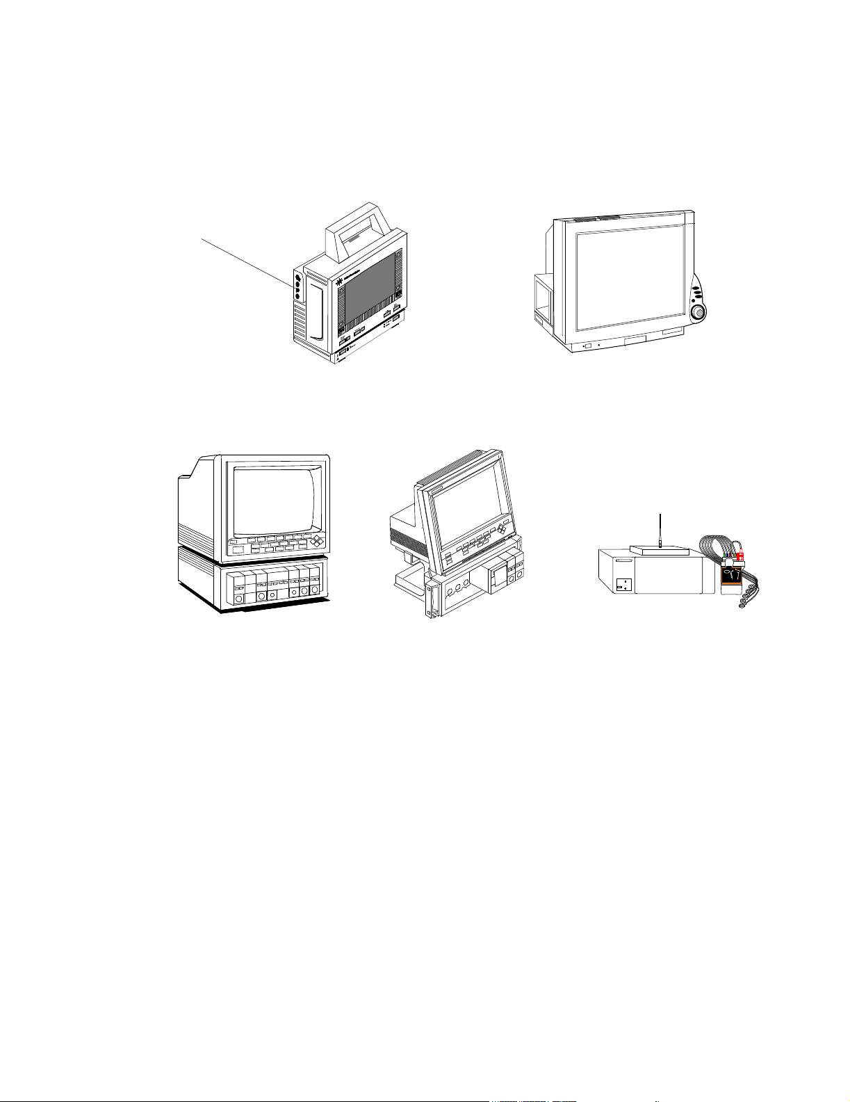
M2/M3/M4
Measurement
Server
Philips Patient Care System
Patient Monitors connecting directly to the Clinical Network
Component
Monitoring System
Clinical Network
Connected
Operation
M2/M3/M4 wired Patient Monitor
M3/M4 wireless Patient Monitor
Patient Monitors on the CareNet
IntelliVue Patient Monitor
IntelliVue Wireless Patient Monitor
24 Patient Monitor
Figure 1-1 Patient Monitors Compatible with the Clinical Network
The Information Centers can be connected to the Clinical Network and can provide full
Clinical Network/Database Server functionality.
When the Information Center is connected to the Clinical Network with a Database Server,
displayed patient monitoring data are transmitted to the Database Server for storage. Real-
time and stored data are then available for review by any other Information Center on the
Network.
Philips Telemetry
System
Information
Center Client
For Network connected Information Centers, no patient data are stored in the Information
Center workstation, except when the Network or Database Server is experiencing a failure. If
the Network or Server becomes unavailable for more than 60 seconds, all Information Centers
and Clients on the Network reboot and go into local database mode. Patient data are
temporarily stored in the Information Center workstation but are lost when the system returns
to normal operation.
With Network/Database Server operation, Information Center Clients can also be connected
to the network as patient data review stations. The Client can display real-time monitoring
Introduction
1-3
Page 18
Philips Patient Care System
data for any patient monitored by any Information Center on the Network and can review any
patient’s data stored in the Server. The type of access to patient data by a Client (Full Control,
Read Only, or No Access) is controlled by the Information Center that sources the data.
The Client has essentially the same performance features as the Information Center except
that it cannot be connected to a CareNet switch and does not receive patient data directly from
patient monitors. It can be located at cabling distances up to 1,200 m (3936 ft.) from the
Network switch to provide patient data review capability at multiple, distant hospital
locations. Release E.01 supports the connection of Clients for remote monitoring over a T1/
E1 line.
Networks Information Centers can operate on two different Philips networks -- the Clinical Network and
then Philips CareNet.
Philips CareNet The Philips CareNet consists of the Philips Serial Distribution Network (SDN) and System
Communications Controller (SCC), and Philips CareNet Controller (PCC) which serves as the
CareNet switch for transmitting and managing patient data among patient monitors and
central stations. A CareNet switch can support up to 24 patient monitors (hardwired or
telemetry) and 6 central monitors. Detailed information on the CareNet is provided in the
SDN/PCC Installation and Service Manual. A CareNet with connection to the Network
and Database Server is shown in Figure 1-2.
Philips
Compatible
Bedside
Monitors
Philips
Te le m et r y
Monitoring
System
Philips CareNet
CareNet
Switch
Figure 1-2 CareNet connected to Clinical Network and Database Server
4 Channel
Recorder
2 Channel
Recorder
IntelliVue Information Center
Workstation
Speaker
UPS
HP LaserJet Printer
IntelliVue Clinical Network
IntelliVue
Patient
Monitors
Network Switch
Option #C22
M2/M3/M4
Bedsides
Database Server
Hospital
Intranet
18.5
1-4 Introduction
Page 19
Philips Patient Care System
Clinical Network The Clinical Network consists of industry standard components and cabling that provide
low-cost network installation and maintenance. Up to 8 Information Centers and 8
Information Center Clients can be connected to the Network and at cabling distances up to
1,200 m (3936 ft.) from a Network switch. The Clinical Network can also be used to connect
up to 16 IntelliVue Patient Monitors (wired) or M3/M4 patient monitors (wired and wireless)
directly to an Information Center.
Standard components for constructing the Clinical Network include the following active
components and cabling:
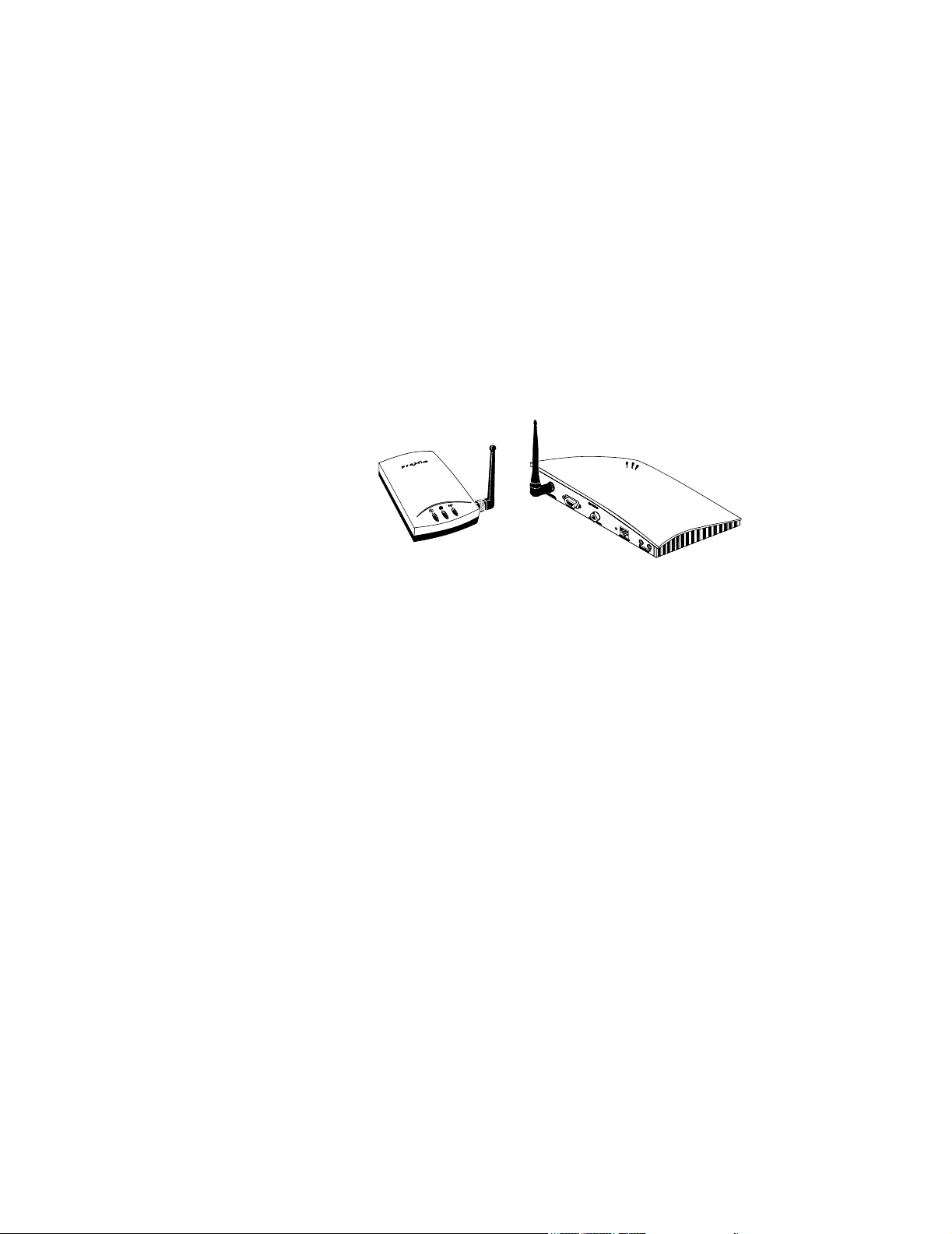
Wireless Access Points connect wireless M3/M4 to the Network. The wireless Access Points
can connect to any switch in the Network (Core, Edge, or Extension) using a 10 Mbps Half
Duplex connection. They must be spaced at least 3 m (10 ft.) apart. The Access Points used
are shown in Figure 1-3.
Figure 1-3 Wireless Access Points
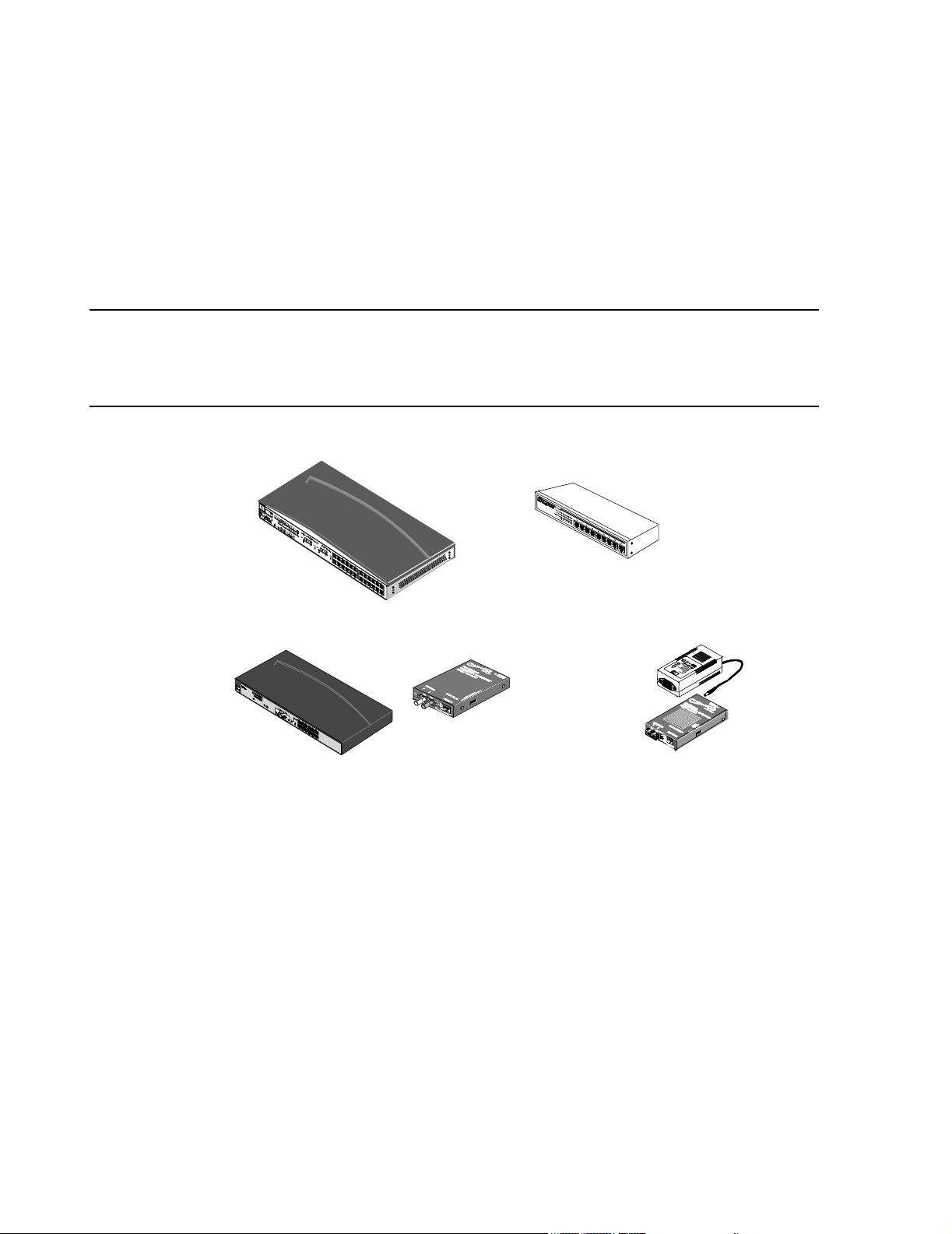
Network switches connect Information Centers and Database Servers to the Clinical Network
and are industry standard, rack mountable, workgroup switches with RJ-45 ports. The
HP2524 switch (Core or Edge) has 24 10/100 Mbit UTP ports and 2 optional 100 Mbit fiber
ports. The 10 Mbit ports connect to M2/M3/M4s, IntelliVue Patient Monitors, Access Points,
and Printers. The 100 Mbit ports connect to Information Centers, Clients, Application
Servers, Database Servers or another Network switch. See Figure 1-4. The Extension switch
(available in limited geographies) has 8 10/100 Mbit UTP ports for connecting small clusters
of devices to either a Core or Edge switch.
Network cabling for interconnecting devices can be industry standard, UTP Category 5 cable
or 62.5/125 micron, multimode, fiber optic cable. UTP cable (orange colored) is available
from Philips in bulk and in several patch cable lengths. Fiber optic patch cables are also
available from Philips Medical Systems.
Media translators interconnect UTP and fiber optic cable for extending cable distances to
1000 m (3280 ft.) from a Network switch. See Figure 1-4.
Introduction
1-5
Page 20
Philips Patient Care System
Patch panels and wall box kits provide for interfacing devices to the network. 24 port patch
panel kits and dual and quad wall box and surface mount kits with UTP, Category 5, RJ-45
terminations are available for US installations. Single UTP wall box kits are available for nonUS installations.
Active Network components - switches, repeaters, media translators - are shown in Figure 1-
4.
Note Specific switches, media translators and access points shipped with systems may vary with
date of purchase as newer models are substituted when they become available. Throughout this
Manual, only general descriptions of devices that are subject to change is provided. For more
detailed information, refer to the device manuals.
24 Port Switch
10 Mbit/s Media Translators
8 Port Switch
100 Mbit/s Media Translator
Figure 1-4 M3185 Clinical Network Components
Power
Supply
1-6 Introduction
Page 21
Philips Patient Care System
Patient Care Systems
Clinical Network
Without a
Database Server
Wired M3/M4
Patient Monitors
Wired
IntelliVue Patient Monitors
Using the capabilities of the Clinical Network and Database Server, Philips Patient Care
Systems can be designed to meet a wide range of clinical monitoring requirements. Examples
are given below -- a relatively simple system using wired and wireless M3/M4 and IntelliVue
Patient Monitors (Figure 1-5), the Network and a relatively complex system showing full
Patient Care System capabilities (Figure 1-6), and a Network using the Small Database Server
(Figure 1-7).
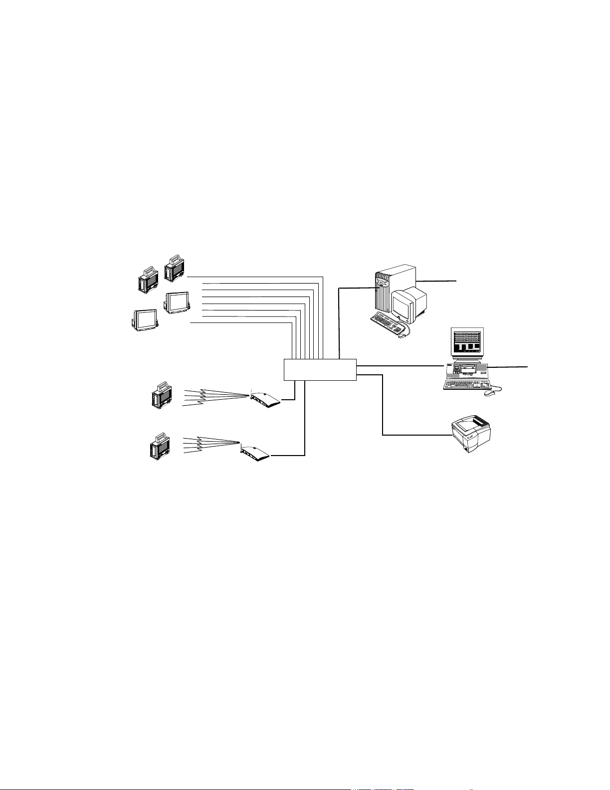
A Patient Care system using the Clinical Network to connect M3/M4 (wired and wireless)
and IntelliVue Patient Monitors to an Information Center is shown in Figure 1-5. In this
application, the Clinical Network supports 1 Information Center, 1 Application Server, 2
LaserJet Printers and 16 patients. The Database Server is not required in this application.
IntelliVue Clinical Network
Network
Switch
Application Server
Hospital LAN
18.5
16 patients
Information Center
Hospital LAN
Wireless
M3/M4 Monitors
Clinical Network
With
IntelliVue
Database Server
Access Points
LaserJet
Printer
Figure 1-5 Clinical Network with Patient Monitors, Information Center and
Application Server
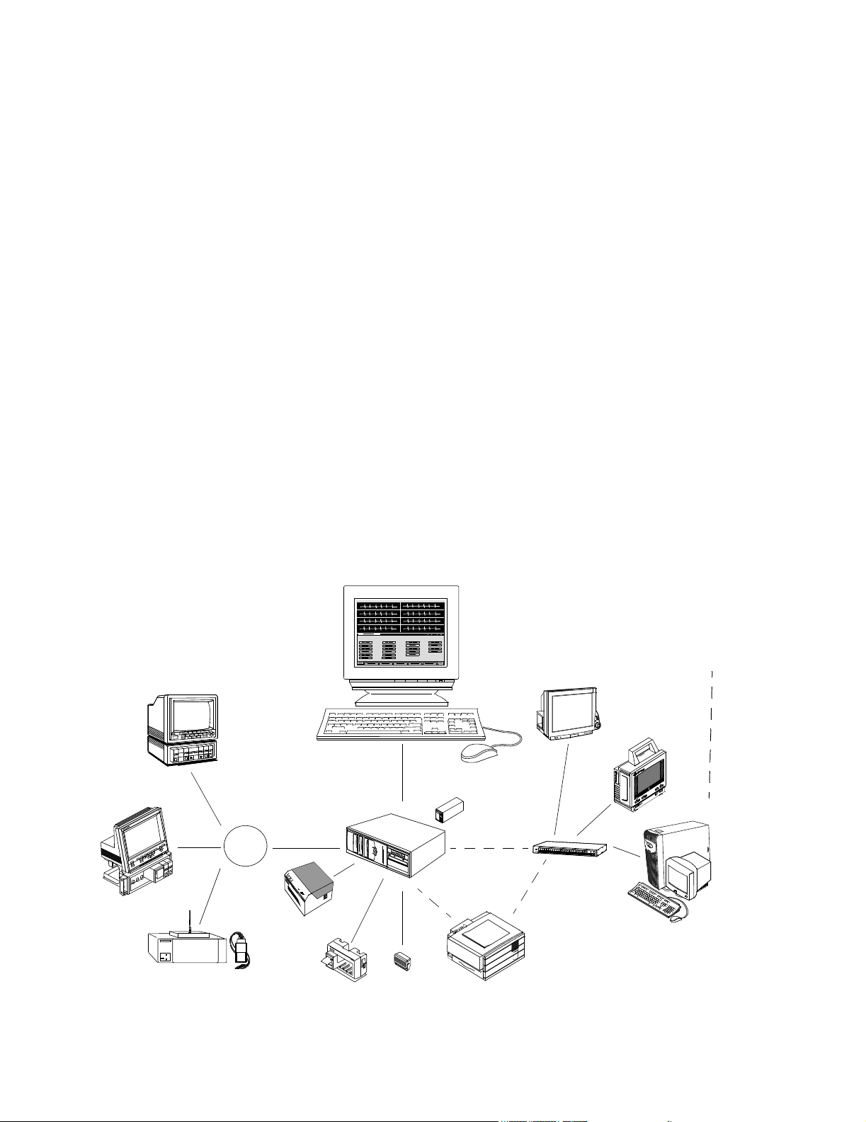
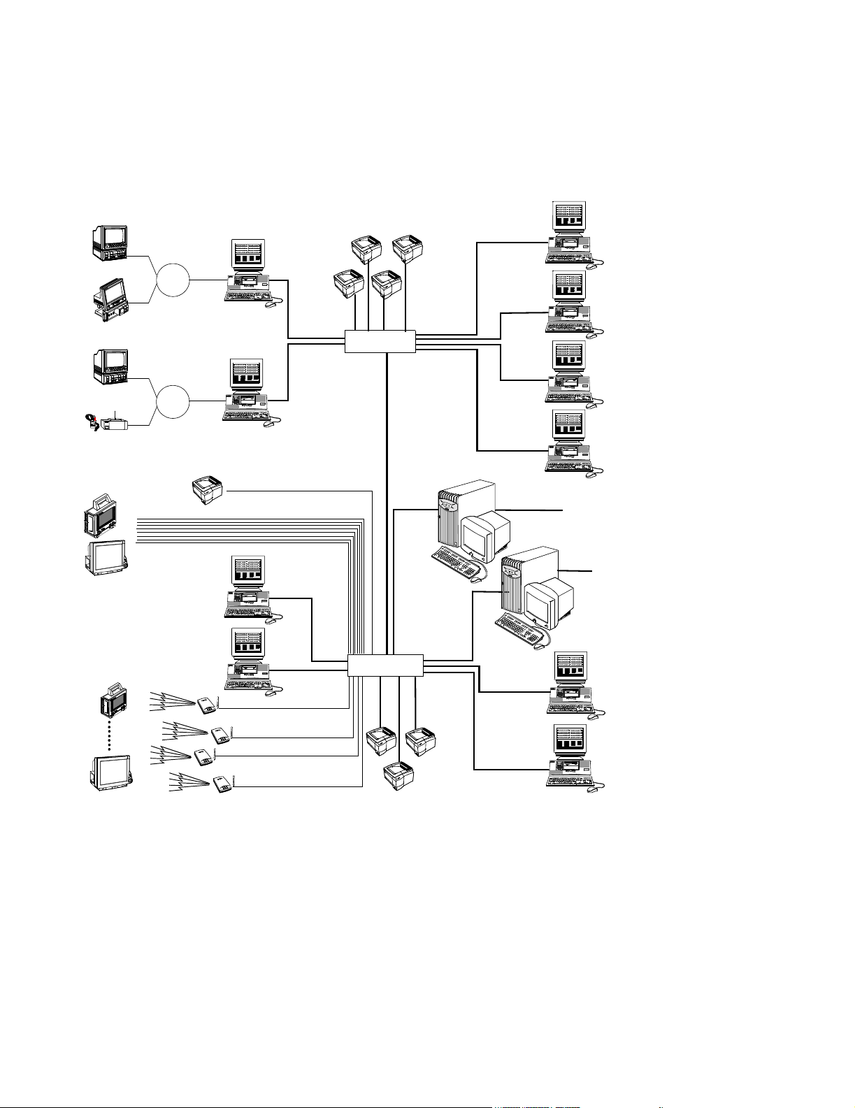
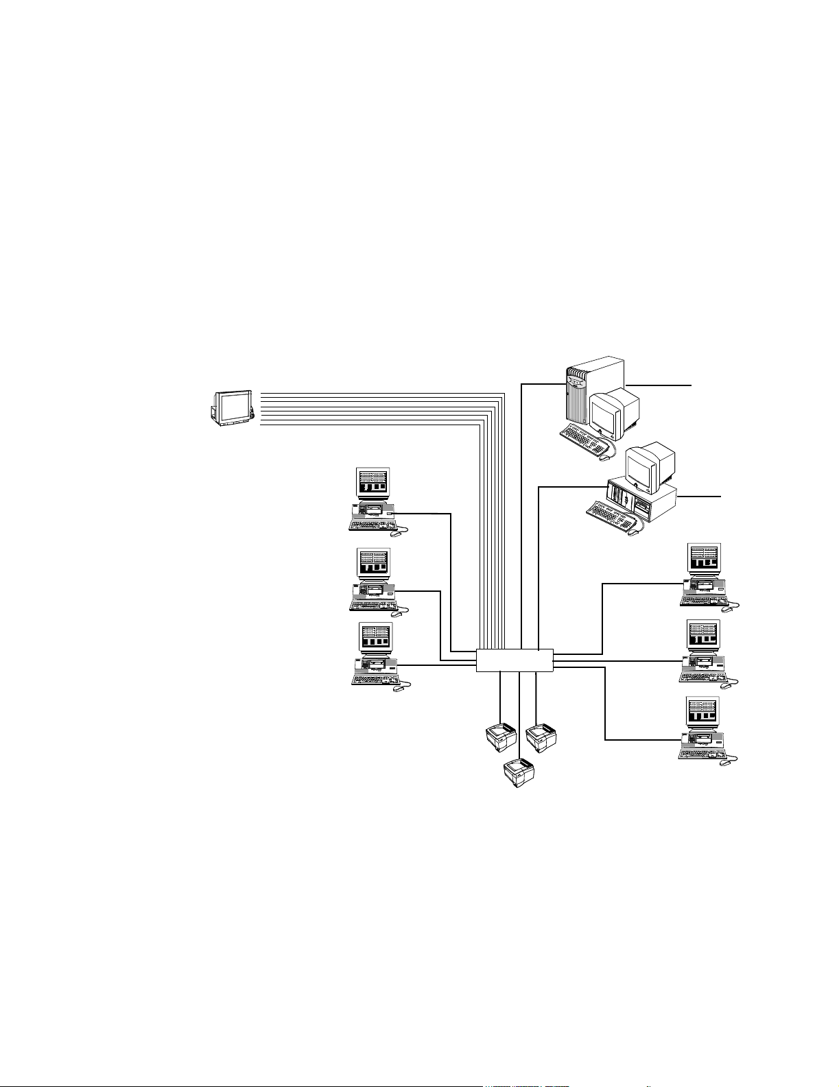
A Patient Care System using the Clinical Network and IntelliVue Database Server is
shown in Figure 1-6. Patient monitoring data from Philips bedside monitors -- CMS, 24 -and telemetry monitors are transmitted to Information Centers via the CareNet switch. Data
from Information Centers are transmitted to the Server via Network switches where they are
stored. The Server can store up to 96 hours of patient data for up to 128 monitored patients,16
max per Information Center, and 32 transfer patients. This Network system can support 1
Application Server, up to 8 Information Centers, 8 Information Center Clients, and 8 LaserJet
Printers.
Introduction
1-7
Page 22
Philips Patient Care System
CMSs
24s
CMSs
Tel e me tr y s
Wired
M2/M3/M4 Monitor
Wired
IntelliVue Patient Monitor
CareNet
16 patients
CareNet
Switch
16 patients
CareNet
Switch
LaserJet Printer
M3150
Information
Center
M3150 Information Center
M3150 Information Center
10Mbps
16 patients
IntelliVue Clinical Network
LaserJet Printers
10 Mbps
100 Mbps
Network Switch
100 Mbps
100 Mbps
M3154 IntelliVue
Database Server
128 patients
(max)
100 Mbps
12 patients
M3151
Clients
12 patients
12 patients
M3151
Clients
12 patients
100 Mbps
18.5
HIS LAN for
web access
M2385
Application Server
HIS LAN for
web access
100 Mbps
Wireless IntelliVue &
M3/M4 Monitors*
M3151
Clients
16 patients
M3151
Clients
16 patients
18.5
M3150
Information
Center
Access Points
Access Points
16 patients
100 Mbps
Network Switch
10 Mbps
LaserJet
Printer
100 Mbps
Figure 1-6 Clinical Network with IntelliVue Database Server
Up to ten M3154 Database Servers systems can be interconnected on the hospital LAN. This
connectivity provides Information Centers with the ability to transfer patient data to a clinical
unit outside of its Database Server. Retrospective data, near real-time waves, parameters, and
alarms for patients across care units that are on separate database servers can also be
reviewed. If a M2385 Application Server is present, web-based applications can be displayed
on the Information Centers.
1-8 Introduction
Page 23
Philips Patient Care System
Clinical Network
With
IntelliVue Small
Database Server
IntelliVue Clinical Network
Wired
IntelliVue Patient Monitor
A Patient Care System using the Clinical Network and the IntelliVue Small Database
Server is shown in Figure 1-7. Patient monitoring data from Philips bedside monitors --
CMS, 24 -- and telemetry monitors are transmitted to Information Centers via the CareNet
switch. Data from Information Centers are transmitted to the Server via Network switches
where they are stored. The Server can store 48 hours of patient data for up to 48 monitored
patients,16 max per Information Center, and up to 12 transfer patients.
This Network system can support 1 Application Server, up to 3 Information Centers, 3
Information Center Clients, and 4 LaserJet Printers.
Application Server
Information
Center
10 Mbps
16 patients
100 Mbps
48 patients
(max)
100 Mbps
100 Mbps
18.5
Small Database Server
5
.
8
1
HIS LAN for
web access
100 Mbps
HIS LAN for
web access
M3185 Clinical Network
Switches Communication and data transfer among devices on the Network is managed by network
Information
Center
Information
Center
16 patients
16 patients
100 Mbps
Network Switch
10 Mbps
LaserJet Printers
16 patients
Clients
16 patients
Clients
16 patients
Figure 1-7 Clinical Network with IntelliVue Small Database Server
The Clinical Network provides networking capability for sharing patient monitoring data --
real-time and stored -- among all Information Centers and Clients connected to the Network.
switches.
Introduction
1-9
Page 24

Philips Patient Care System
Network
Connections
Network connections between Information Centers, Clients, Application Servers, Database Servers and the switches are 100 Mbps. 10/100 Mbit/s interface cards in these
devices provide the Network connections.
Extended
Distances
Extension Switches, fiber optic cable, and media translators permit Network devices to be
located at widely separated places in the hospital. Hence, patient monitoring data can be made
available to many clinicians both within and outside the clinical environment.
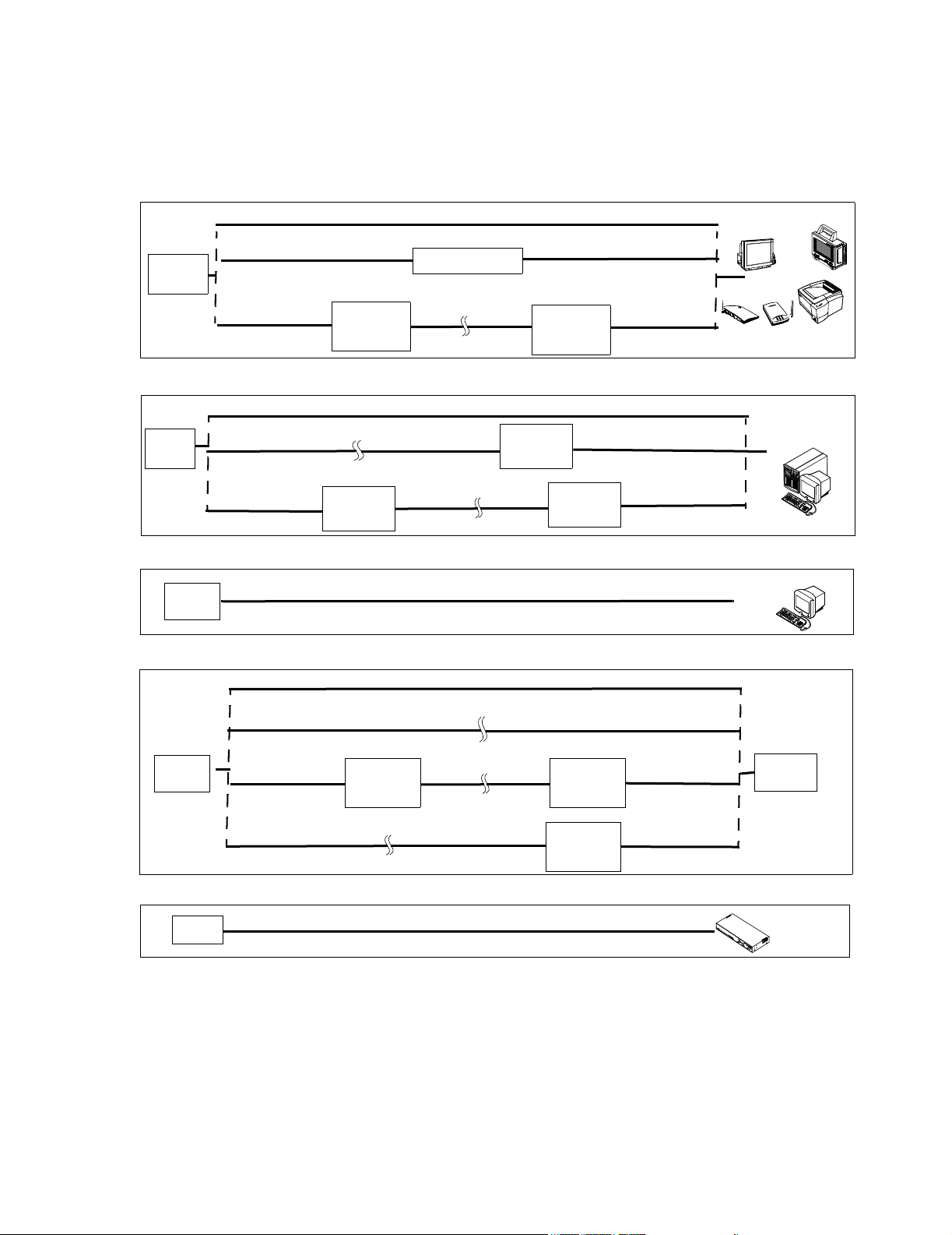
The following design rules govern point-to-point cable distance capabilities and limitations
between Network devices. See Figure 1-8.
• Switch to wired M3/M4 monitor, wired IntelliVue Patient Monitor, Access Point, and
LaserJet Printer (10 Mbps connection)
Note All lengths assume 2 patch cables (< 5 m each) and a single cable length in between is used. So
single length = patch cable + other cable + patch cable.
• Switch to Information Center/Client (100 Mbps connection)
• Switch to Database Servers (100 Mbps connection)
• Switch to Application Server (100 Mbps connection)
• Switch to Switch (100 Mbps connection)
These connections are described in detail in Chapter 3.
1-10 Introduction
Page 25
Core/Edge
Switch
Core/Edge
Switch
Switch to Network Device Options (10 Mbps)
UTP Cat 5 Cable, 100 m max
UTP Cat 5 Cable, 100 m max
100 m max
10 Mbit/s
Media
Translator
Repeater
Fiber Optic CableUTP Cat 5 Cable
1000 m max
UTP Cat 5 Cable, 100 m max
10 Mbit/s
UTP Cat 5 Cable
100 m max
Media
Translator
Switch to Network Device Options (100 Mbps, FULL Duplex)
UTP Cat 5 Cable, 100 m max
Fiber Optic Cable
1000 m max
UTP Cat 5 Cable
100 m max
100 Mbit/s
Media
Translator
100 Mbit/s
Translator
Fiber Optic Cable
1000 m max
Media
UTP Cat 5 Cable
100 m max
100 Mbit/s
Media
Translator
UTP Cat 5 Cable
100 m max
Philips Patient Care System
M2/M3/M4 Moni tor
IntelliVue Monitor
LaserJet Printer
Access Points
IntelliVue Database
Server, Application
Server
18.5
Switch
Switch
Switch
Switch to Network Device Options (100 Mbps, HALF Duplex)
UTP Cat 5 Cable, 100 m max
Switch to Switch Options (100 Mbps)
UTP Cat 5 Cable, 100 m max
Fiber Optic Cable, 1000 m max
UTP Cat 5 Cable
100 m max
100 Mbit/s
Media
Translator
Fiber Optic Cable, 1000 m max
Fiber Optic Cable
1000 m max
100 Mbit/s
Media
Translator
100 Mbit/s
UTP Cat 5 Cable
100 m max
UTP Cat 5 Cable
100 m max
Media
Translator
Switch to Access Point Controller Option
UTP Cat 5 Cable, 100 m max
Figure 1-8 M3185 Network Point-to Point Cable Distance Options
IntelliVue Information
Center
18.5
Switch
Access Point Controller
Introduction
1-11
Page 26

Components and Options
Components and Options
Clinical Network systems can include the Information Center and Information Center Client,
the IntelliVue Database Server, IntelliVue Small Database Server, Application Server, and a
selection of switches, media translators, and cabling.
The following components are available for the M3185 Clinical Network
Active Components
989803131221 100-FX SC Transceiver (Fiber Port) for the 862084 Switch
989803131231 AP Power over LAN Module
Table 1-2. Active Components for M3185 Clinical Network
Option Description
862084 High Density Managed Switch (Core/Edge)
862085 Low Density Unmanaged Switch (Extension Switch)
862086 10 Mbit/s UTP repeater
862088 10 Mbit/s media translator pair
862089 100 Mbit/s media translator
862105 Harmony Access Point Controller
862092 Harmony Access Point
862093 Remote Power Supply
862095 Bedside Wireless LAN Adapter
Purchased Options
Cabling Installation Materials
Table 1-3. Purchased Option for M3185 Clinical Network
Option Description
862099 650 VA UPS
Cabling installation materials are ordered under Product # M3199AI.
Table 1-4. M3199AI Passive Components for M3185 Clinical Network
Option Description
UTP Cable
P01 305 m (1000 ft.) Unshielded Twisted Pair (UTP) plenum cable (Cat. 5,
Orange)
Patch Cables
J10 0.9 m (3 ft.) UTP Patch Cable
J11 2 m (7 ft.) UTP Patch Cable
J12 3.7 m (12 ft.) UTP Patch Cable
J20 3.7 m (12 ft.) UTP Crossover Cable
J21 0.9 m (3 ft.) UTP Crossover Cable
J30 3.0 m (9.8 ft.) Fiber Optic Patch Cable - ST/ST
1-12 Introduction
Page 27

Components and Options
Table 1-4. M3199AI Passive Components for M3185 Clinical Network
Option Description
J31 3.0 m (9.8 ft.) Fiber Optic Patch Cable - SC/SC
J32 3.0 m (9.8 ft.) Fiber Optic Patch Cable - ST/SC
Patch Panel Kits
A01 24-Port Patch Panel Kit
A05 Patch Panel Wall Mount Kit
Wall Box Kits
A10 Dual Port, single gang, RJ-45 UTP Wall Box Kit (US only)
A11 Dual Port, single gang, RJ-45 UTP Surface Mount Kit
A12 Quad Port, dual gang, RJ-45 UTP Wall Box Kit (US only)
A13 Quad Port, dual gang, RJ-45 UTP Surface Mount Kit
Mounting Options
The following mounting options are available for Network Components.
The following options are ordered under Product # M3180A.
Table 1-5. M3180A Mounting Options for the Clinical Network
Option Description
A22 Harmony Access Point Steel Enclosure Kit
Introduction
1-13
Page 28

Components and Options
1-14 Introduction
Page 29

Overview
2
Hardware Description
Clinical Network support personnel should be familiar with Local Area Network (LAN)
hardware and cabling. Only brief descriptions of these subjects are given in this manual.
Chapter 2 overviews the Clinical Network hardware in the following sections:
System Components . . . . . . . . . . . . . . . . . . . . . . . . . . . . . . . . . page 2-2
Specifications . . . . . . . . . . . . . . . . . . . . . . . . . . . . . . . . . . . . . . page 2-22
Regulatory . . . . . . . . . . . . . . . . . . . . . . . . . . . . . . . . . . . . . . . . . page 2-26
Hardware Description 2-1
Page 30

System Components
System Components
Hardware components of the Clinical Network are primarily industry standard equipment
tailored to LAN applications.
These hardware components can change frequently as newer models with improved cost and
performance specifications become available. Therefore, this section provides only general
descriptions of the Clinical Network hardware and illustrates typical units supplied at the date
of the manual’s printing.
Documentation on specific units shipped with customer orders is included with the unit.
Warning Components, topologies, and configurations specified by Philips have been optimized and
tested to meet a variety of patient monitoring standards. Hardware and software
products not supplied by Philips as part of an Information Center system are not
approved or supported by Philips for use with Information Center and Clinical Network/
Database Server systems.
Active hardware components for the Clinical Network include the items listed in “Active
Components” on page 1-12. These are described in the following sections.
Warning Refer to Chapter 3 for which active Clinical Network components must be connected to a
UPS to assure continuity of operation during brief electrical power interruptions.
2-2 Hardware Description
Page 31

System Components
Core/Edge Switches
24-port Network Switches are used to route patient monitoring data among the devices on
the Clinical Network. It “reads” incoming data from network devices -- Patient Monitors,
Information Centers, the Server, another Switch -- and routes them to their destination devices
-- other Information Centers, the Server, Printers. The HP ProCurve 2524 (J4813A) switch
used is rack mountable. Its front panel has 24, 10/100 MBit/s RJ-45 port connections, two
slots for installing supported 100Base-FX transceivers (for fiber optic cable (SC connector)),
and a DB9 Console port for configuring the switch. The rear panel contains an ac power
supply connection, and a cooling vent outlet. Its internal power supply is auto switching to
AC input voltages of 100 - 127V and 200 - 240V. See Figure 2-1.
Core/Edge Network Switch
Power/Fault
LEDs
Self Test and Fan
Status LEDs
Power
Fault
Port
hp procurve
switch 2524
j4813a
Console
Reset Cle ar
Reset and ClearConsole
Buttons
Buttons
Self
Fan
Test
Status
LED Mode Select
Link
Mode
Link
Mode
Slots for 100Mbps
10/100Base-TX RJ45 ports Reset and Clear
Transceivers
Front Panel
Rear Panel
Figure 2-1 24 Port Core/Edge Network Switch
If the system has been upgraded from an earlier release, the Cisco 1900 switch can only be
used as an Edge switch to connect 10 Mbps devices. The rules and guidelines for this are
given in “Upgraded Systems” on page 3-11.
AC Power InCooling Vent
Hardware Description
2-3
Page 32

System Components
Extension Switch/ Repeater
An Extension Switch is used to allow small clusters of devices to be connected to the system
from a remote location. Up to seven devices can be connected to the Extension switch. There
is no maximum number of Extension switches specified per system.
A repeater is used to extend the distance for UTP cable between a switch and any 10Mbit
Network device (Refer to Chapter 3 for details). The maximum standard CAT5 length of a
single, continuous, UTP cable is 100 m (328 ft.). A maximum of 1 repeater can connect 2,
continuous-length 100 m cables to achieve a total cabling distance of 200 m (656 ft.) between
a Switch and any Network device.
The Switch has 8 UTP ports. Networked Devices are connected to the first 7 ports and the
Network Switch is connected to Port 8MDI. The Allied Telesyn AT-FS708 switch is used for
the Extension switch. See Figure 2-2.
Extension Switch/
Repeater
Power LED
Port Status LEDs
Figure 2-2 Network 8-Port 10/100 Mbit/s Extension Switch & Repeater
POWER
LINK/ACT
100M
FULL/COL
1 2 3 4 5 6 7 8
1X 2X 3X 4X 5X 6X 7X 8MDI-X 8MDI
OR
Ports 1 - 7
(to Network Devices)
Port 8MDI
(to Network Switch)
100-240-50Hz 0.4A
Power Cord Connection
2-4 Hardware Description
Page 33

System Components
Wireless Access Points
Wireless Access Points provide the interface between wireless IntelliVue/M3/M4 Patient
Monitors and the Clinical Network. Access Points must be spaced at least 3.0 m (10 ft.) apart.
The Harmony Access Point is shown in Figure 2-3 along with rear panel connections and
LED indicators. An external 12 VDC (1.2 A) power supply (included) is required to provide
power. The power supply can accept AC input voltages in the range of 100 - 250 VAC. Power
to the Harmony Access Point can also be provided via the Remote Power System, in this case,
the power supply is not included. Harmony Access Points require an Access Point Controller
on the network.
Warning The Harmony Access Point must be operated at least 15 cm (6 inches) from any person.
This is necessary to insure that the product is operated in accordance with the RF
Guidelines for Human Exposure.
Serial Port
LAN
Link LED
Status LED
Radio LED
Ethernet LED
Power In
Master LED
Figure 2-3 Harmony Wireless Access Point
The Harmony Access Point LAN port requires a crossover cable as shown in Figure 2-4. If a
crossover cable is not available, a crossover adapter that is shipped with the Harmony Access
Point can be used to support this requirement. See Figure 2-5.
Hardware Description
2-5
Page 34

System Components
Crossover LAN Cable
Figure 2-4 Harmony Access Point crossover cable
Access Points
Mount Kit
Access Point Mount Kits are available for mounting the Access Points and its power supply.
Refer to their Installation Notes for more information.
2-6 Hardware Description
Harmony Access Point crossover adapter
non crossover LAN Cable
Figure 2-5 Harmony Access Point crossover adapter
Page 35

System Components
Access Point Controller
Power LED
The Access Point Controller provides management, filtering, and security services for the
Harmony Access Points and status information for the RangeLAN2 Access Points in the
Clinical Network. The Access Point Controller (Figure 2-6) allows for single point systemwide updates to all the Harmony Access Points on the network through the controller’s web
interface.
Access Point
Controller
Network Utilization LEDs
AC Power In
Front Panel
Rear Panel
Serial Port
Ethernet In
Figure 2-6 Access Point Controller
100 Base-T LED
Link/ACT LED
Hardware Description
2-7
Page 36

System Components
Remote Power System
The Remote Power System provides remote DC power to Harmony Access Points over
standard Category 5 twisted pair ethernet cables eliminating the need for AC outlets, UPS and
AC/DC Adapters for the Access Points. The Power System (Figure 2-7) connects to a
PowerDSine Power Over LAN module (Figure 2-8) which connects to the Harmony Access
Point.
Output and Input Ports
1 2 3 4 5 6
Data &
Power
Data
IEEE 802.3AF Compliant
POWERDSINE
POWERDSINE 6006
AC
CONSOLE 48VDC
Front Panel
Rear Panel
Figure 2-7 Remote Power System
Console Port
AC Power In
2-8 Hardware Description
Page 37

System Components
AP Power Over LAN
Harmony Access Point
Crossover Adapter
The AP Power Over LAN module (Figure 2-8) connects to the Harmony Access Point to the
Remote power System (Figure 2-7). Figure 2-9 shows a Power System component connection
diagram.
Power Over LAN Module
(shown here connected to the Harmony Access Point)
UTP port for connection
to Remote Power System
Data
Power
Power & Data Power
Harmony
Access Points
Power over
LAN Modules
Power System
Data & Power Ports
Switch
Data Ports
hp procurve
switch 2524
j4813a
Power
Fault
Console
Reset Cl ear
1 2 3 4 5 6
Data &
Power
Data
Self
Fan
LED Mode Select
Test
Status
Figure 2-8 AP Power over LAN Module
Link
Mode
Link
Mode
Figure 2-9 Harmony Power System Overview
Power Over LAN Modules
connect to the top row of ports
on the Remote Power System
POW-
POWERDSINE
AC
IEEE 802.3AF Compliant
CONSOLE 48VDC
Switches connect to the bottom
row of ports on the
Remote Power System
Hardware Description
2-9
Page 38

System Components
Wireless Bedside Adapter
The Wireless Bedside Adapter is shown in Figure 2-10 along with rear panel connections
and LED indicators. Mounting of this adapter to the IntelliVue Patient Monitor is shown in
Figure 2-11
Status LED
Radio LED
Ethernet LED
Link LED
Master LED
Figure 2-10 Wireless Bedside Adapter
Figure 2-11 Wireless Bedside Adapter Mounting
2-10 Hardware Description
Page 39

System Components
Media Translators
Media translators are used to interconnect UTP and fiber optic cable. Fiber optic cable permits
significantly longer cabling distances than UTP and greater immunity from noise. Continuous
fiber optic cable lengths can be 1,000 m (3,280 ft.). Refer to Figure 1-8 as well as Chapter 3 for
descriptions and an overview of how and where the Media Translators are used.
Note The maximum number of Media Translators in series is 2.
One of the supported 10 MBit/s Media Translator is the E-TBT-FRL-05 model manufactured by
TRANSITION Networks and shown in Figure 2-12. It is compatible for use in IntelliVue
Clinical Networks for all 10 Mbit/s devices. Rear and Front Panels are shown in Figure 2-13 and
Figure 2-14 respectively. An External Power Supply provides power to the device through a rear
panel connection as shown in Figure 2-13.
Figure 2-12 10 MBit/s Media Translator
LinkALERT
Enable Disable
Set to Disable
External Power
Supply
Figure 2-13 Rear Panel of the 10 MBit/s Media Translator
RX Connector
RJ-45 ConnectorTX Connector
RXTX
Lin
RX
10Base-
Lin
RX
Pw
10Base
Figure 2-14 Front Panel of 10Mbit/s Media Translator
The front panel contains a female, 10-Base-T RJ-45 connector for connecting the UTP cable and
female, 10Base-FL TX (transmit) and RX (receive) connectors for connecting the fiber optic
cable. The Media Translator allows either straight through or crossover cables to be used. The
Hardware Description
2-11
Page 40

System Components
unit determines the characteristics of the cable connection and automatically configures to
link to straight through or to crossover cable.
The LinkALERT feature is set to Disable to allow troubleshooting of device-to-device
connectivity using the Link LEDs.
Note The LinkALERT switch on the side of the unit must be set to Disable. See Figure 2-12.
The other supported 10 Mbit/s media translator pair is the HP J3300A with an HP J2606A
fiber transceiver installed in its AUI front panel port. The transceiver permits the device to
serve as a 10 Mbit/s media translator with one front panel RJ-45 port as the UTP connection
and the transceiver as the fiber optic connection. See Figure 2-15.
Caution Only one input port and one output port can be used with this Media Translator.
Xcrv LED
H
HP J3300A
10Base-T Hub-12
Power
Fault
Power ON LED
Fault LED
J3300A Repeater
J2606A Transceiver
6
1 2
3
4
5
Xcvr
8
7
9
10
12
11
Reset
Port Status LEDs
10 Mbps Xcrv Port
Act
Col
Fiber Optic
Input and Output Ports
Front Panel
Light Status LED
Status
Light
Fiber-Optic
Rx
10 Mbit/s Media Translator
1 2X 3X 4X 5X 6X
Port 1 Only
MDI
MDI-Xr
(in)
(out)
7X 8X 9X 10X 11X 12X
UTP
Input and Output Ports
2-12 Hardware Description
Figure 2-15 J3300 10 Mbit/s Media Translator
Page 41

System Components
The 100 Mbit/s media translator connects UTP and fiber optic cable between two switches
or between the Core Switch and the Database Server. The device used is the Transition
Networks 100BASE-TX/100BASE-FX Media Converter, which provides an RJ-45 twisted
pair 100Base-TX connector and an RX and TX SC 100Base-FX connector to 1300 nm
multimode fiber optic cable. It is shown in Figure 2-16 along with its front and rear panel
connections and side panel switches. Configuration switches on the side of the unit are used to
set the required duplex settings (see below). An external 9 VDC (.55A) power supply
(included) is required to provide power. The power supply can be set to input voltages of
either 100-120 VAC or 220-240 VAC with a switch.
Power Supply
100 Mbit/s Media Translator
Power Supply
Rear Panel
Input
E-100BTX-FX-04 Configuration Switch Settings
E-100BTX-FX-04 Configuration Switch Settings
Auto-Negotiate
U U D D
100 Full
D U D D
Figure 2-16 100 Mbit/s Media Translator
Fiber Optic
Input and Output Ports
UTP
Input and Output Ports
Configuration
Switches
Front Panel
1 2 3 4
Side Panel
E-100BTX-FX-05 Configuration Switch Settings
Auto-Negotiate
U U D D
100 Full
D D D D
Hardware Description
2-13
Page 42

System Components
Printer An HP LaserJet Printer with connectivity to the Clinical Network (Option M3159A
#A02) is available for printing patient and configuration data. See Figure 2-17. The Printer
is connected to a Switch port via a 10 Mbit/s, UTP cable. It is a 10 Mbit connection. See
Figure 1-8.
The Network connection is made via a Jet Direct card, (included with Option M3159A
#A02), it is installed in the rear right side of the Printer. See Figure 2-17, where the RJ-45
port and AC power connector are also shown.
Warning Do not use any other printers or printer drivers.
Note For additional information on Printer performance, see the Printer’s documentation manual
and the HP LaserJet Quick Reference Service Guide.
Top Output Bin
Top cover
(access to print cartridge
and serial/model #)
25 Pin Parallel
Connection
OR
RJ-45 LAN
Connection
Jet Direct
Card
Tray 1
(pull down)
Paper Level
Indicator
Tray 2
Control Panel
2-14 Hardware Description
Figure 2-17 HP LaserJet 2300 Printer
Page 43

System Components
Uninterruptible Power Supply
An Uninterruptible Power Supply (UPS) is available as an option for Network devices. Its
purpose is to provide up to 90 seconds of battery power to maintain system operation and
eliminate time consuming software rebooting during short power transitions.
Warning UPSs are shipped without their internal battery wire connected. Before use, the battery
wire must be connected.
Only Voltage Outputs labeled BATTERY BACKUP should be used for UPS protection.
The UPS for Network devices is 650 VA and it comes in 2 versions -- 100-127 VAC (50-60
Hz) and 220-240 VAC (50-60 Hz). The versions look similar and are shown in Figure 2-18
along with typical front and rear panels.
650 VA UPS
Test
Front Panel
DIP Switches
COMPUTER
INTERFACE PORT
Test
Switch
On/Off
l
Switch
0
ACCESSORY
SURGE
PROTECTION
UPS OUTPUT
120V 50/60 Hz
TOTAL
OUTPUT
CURRENT
12A MAX
4 3 2 1
50-60 Hz
FAULT
OVERLOAD
PROCTECTOR
BATTERY
BACKUP
INPUT
120V-
12A
SITE
WARNING
I/O Port
Overload
Protector
Reset
Switch
Voltage
Outputs
4 3 2 1
!
FULL-TIME SURGE
PROTECTION
SURGE PROTECTION
AND BATTERY BACKUP
650 VA 400W)
+
220-240V-
3.0A, 50/60Hz
230V AC in
Rear Panel 230V
Rear Panel 120V
Figure 2-18 650 VA UPS for Network Components
Hardware Description
2-15
Page 44

System Components
650 VA UPSs have rear panel DIP switches that must be set in specific positions for the UPS
to operate properly. The correct dip switch settings for 120V and 230V models are shown in
Figure 2-19.
Notes The switch settings of Figure 2-19 must be made during installation since they are shipped
with all switches on OFF (down).
1
4
3
2
S4: DOWN
S3: UP
S2: DOWN
S1: UP
120V UPS
Figure 2-19 Rear Panel DIP Switch Settings for 120V and 230V UPSs
Operation The operation of a UPS after power failure is as follows.
Seconds after
power failure Action
0 Line power fails and UPS goes to battery power. Philips systems continue to
run, but displays will be blank (no power).
If line power returns during this period, normal operation is restored
automatically.
90 The Operating System begins a system shutdown and Philips application
software ends.
120-150 The UPS shuts off power to the device. The UPS then typically beeps every 5
seconds until power is restored or the UPS is turned off.
When line power is restored, the UPS automatically supplies power to the
device.
If line power is restored between 90 and 120-150 seconds after power failure,
the system shutdown completes and the computer is powered off. The
following English language message will appear.
2
1
4
3
S4: DOWN for 50 Hz
UP for 60 Hz
S3: DOWN
S2: DOWN
S1: UP
230V UPS
It is now safe to turn off your computer.
Clicking on RESTART initiates a software boot cycle, after which normal
Information Center operation resumes.
Warning After 150 seconds, Information Centers, Clients, and the Server must be manually
restarted following proper restart procedure.
Note Power failure and restoration messages will also appear in the Event Log.
2-16 Hardware Description
Page 45

System Components
M3185
Cables and
Installation
Passive hardware components for the Clinical Network include UTP and fiber optic patch
cables, a variety of RJ-45 wall boxes, and a 24-port patch panel for interconnecting wires.
These are described in the following sections.
Materials
UTP Cable Network signals are transmitted primarily on Unshielded Twisted Pair (UTP) Category 5
(CAT5) cable (orange colored). UTP CAT5 cable is regulated by the Computer
Communication Industry Association (CCIA) according to standards developed by the
Electronic Industries Association (EIA) and the Tele-communication Industries Association
(TIA). These standards, EIA/TIA 568A, were first published in 1991 and their purpose is to
specify generic telecommunication cabling systems to support a multiproduct, multivendor
environment and provide direction for commercial telecommunication product design.
Category 5 is one of the EIA/TIA 568A standards and is limited to runs less than 90 meters
(295 ft.) from the telecommunication closet patch panel to the outlet wall box. It can handle
data transmission rates up to 100 Mbit/s and has an impedance of approximately 100 ohms.
Category 5 UTP cable consists of 4 pairs of unshielded, 24 AWG solid copper wires with
Polyolefin or Fluorinated Ethylene Propylene (FEP) jackets contained in a plenum rated PVC
sheath. The 4 pairs of wires are color coded in pairs as shown in Figure 2-20 with a major
color (blue, orange, green, brown) paired with white as PRIMARY colors and stripes. The
pairs are also numbered -- 1, 2, 3, 4 -- as shown in Figure 2-20.
PVC Sheath
WHITE/blue
BLUE
WHITE/orange
ORANGE
WHITE/green
GREEN
WHITE/brown
BROWN
PRIMARY
COLOR
Jacket
stripe
color
24AWG Solid
Copper Wires
4
3
2
1
Pair #
Figure 2-20 UTP Category 5 Cable Showing Wire Pairing
CAT5 cable is compatible with either the 568A or 568B wiring standards for RJ-45
connectors and jacks. Figure 2-21 shows the pairing scheme and signal assignments used by
UTP cable on the Clinical Network.
Pair 2 of the UTP cable (ORANGE and WHITE-orange wires) receives the Network data.
Pair 2 is connected to pins 3 and 6 of the 568A version and pins 1 and 2 of the 568B versions.
Pair 3 of the UTP cable (GREEN and WHITE-green wires) transmits the Network data. Pair
3 is connected to pins 1 and 2 of the 568A version and pins 3 and 6 of the 568B versions.
Figure 2-21 shows end views of both versions of RJ-45 connectors and jacks.
Hardware Description
2-17
Page 46

System Components
Note Direct connect patch cables and in-wall wiring use the 568A version on both ends.
Cross over cables use a 568A version on one end and a 568B version on the other.
Therefore, they invert the transmission and reception wires.
When purchased from Philips, cross over cables have black boots on cable ends for
identification.
Transmit: Pair 3
568A Version
Pair2
Pair4
Pair1
Pair3
Receive: Pair 2
RJ-45
Connectors
568B Version
Pair3
Pair4
Pair1
Pair2
8 7 6 5 4 3 2 1
BR W-br O W-bl BL W-o G W-g
Pair2
Pair3
Pair1
1 2 3 4 5 6 7 8
W-g G W-o BL W-bl O W-br BR
Figure 2-21 UTP Category 5 Connectors and Jacks
Pair4
RJ-45
Jacks
8 7 6 5 4 3 2 1
BR W-br G W-bl BL W-g O W-o
Pair3
Pair2
Pair1
1 2 3 4 5 6 7 8
W-o O W-g BL W-bl G W-br BR
Pair4
2-18 Hardware Description
Page 47

System Components
Fiber Optic
Cable
For noise immunity or extended distance cabling, multimode fiber optic cable is used. Multimode fiber optic cable consists of a 2-cord pair with each cord having a 62.5 micron fiber optic element core surrounded by 125 micron cladding. Each cord is then surrounded by a thermoplastic buffer layer, a Kevlar jacket, and a PVC sheath. One fiber strand is used for TX (transmit) and the other for RX (receive). See Figure 2-22.
Fiber optic cable is designed for minimal signal attenuation at wavelengths of 850, 1300, and
1550 nanometers. Clinical Network applications uses 1300 nm. A media translator is
required when converting between UTP and fiber optic cables.
Note Single, continuous-length fiber optic cables are limited to 1000 meters (3281 ft.).
PVC Sheath
Kevlar Jacket
62.5 micron Fiber Optic Element
Thermoplastic Buffer Layer
125 micron Cladding
TX (transmit)
RX (receive)
Figure 2-22 Fiber Optic Cable Cross Section
Fiber optic cables can have two different types of connector -- SC and ST -- as shown in
Figure 2-23.
SC connectors have a square cross section and are used with a Switch.
ST connectors have a round cross section and are used with the 10 Mbps Media
Translator
SC Connector
ST Connector
Figure 2-23 Fiber Optic Cable Connectors
Hardware Description
2-19
Page 48

System Components
Wall Boxes RJ-45 wall boxes for UTP cable connectors are available from Philips for connecting Patient
Monitors, Information Centers, Clients, and the Server to the Clinical Network. Both dual port
(Option M3199AI #A10) and quad port (Option M3199AI #A12) wall boxes are available for
US installations. Surface mount kits for mounting dual port wall boxes (Option M3199AI
#A11) and quad port wall boxes (Option M3199AI #A13) are also available. Single port wall
boxes and surface mount kits are also available for certain countries. See your Philips
Representative for specific part numbers.
A dual port RJ-45 wall box is shown in Figure 2-24. Each wall box includes places for
labeling UTP cables connecting to each port. A typical label would include the patch panel
number and port number the cable connects to. For example, a label 2-14 would mean that
the connecting UTP cable came from patch panel 2 - port 14.
UTP wire connections for each pin of port jacks are the 568A Version of Figure 2-21.
Wiring of UTP cables to internal connectors of wall boxes must be performed by a certified
CAT5 cable plant installer. They should be wired as shown in Figure 2-21
Wall Box
Port A Label
RJ-45 Port A
RJ-45 Port B
Port B Label
G
O
R
A
N
B
G
L
U
E
B
R
O
W
R
E
N
E
E
N
RJ-45 Wiring
Connections
8
7
6
5
4
3
2
1
PRIMARY COLOR
BROWN
WHITE/brown
GREEN
WHITE/green
ORANGE
WHITE/orange
BLUE
WHITE/blue
stripe color
2-20 Hardware Description
Figure 2-24 RJ-45 Wall Box and Wire Connections for UTP Cable
Page 49

System Components
F
l
Patch Panels The Clinical Network contains many interconnecting cables and wires. To assure a robust,
reliable, and accessible network, each wire connection must be secure, and identification of
wires and cables must be clear. To assist this process, 24-Port Patch Panels are available
from Philips (Option M3199AI #A01). For large systems with many wires, it is recommended
that patch panels be mounted in a floor standing rack designed for that purpose. However,
Philips also provides a Patch Panel Wall Mount Kit (M3199AI #A05) for mounting the
patch panel on a vertical wall.
The 24-port patch panel from Philips is shown in Figure 2-25. The Front Panel has 24, RJ45 ports for connecting 24, UTP CAT5 RJ-45 connectors. Each front panel port should be
labeled for cable identification. Places for port labeling are provided. Snap-in Philips labels
are also included for each port.
The Rear Panel has 24 sections for connecting the 8 individual wires from 24 different UTP
CAT5 cables. Wiring of UTP cables to the rear of the Patch Panel must be performed by a
certified CAT5 cable plant installer. They should be wired as shown in Figure 2-25.
ront Pane
12345 6
AMP
Category 5
789101112 131415 16 17 18 192021 22 23 24
24
23
ORANGE
BLUE
WHITE/blue
BLUE
1
23
untwisted no more
than 1.3 cm (0.5 in.)
RJ-45 Ports
2022
21
19
Rear Panel Wiring Connections
GREEN
WHITE/orange
ORANGE
WHITE/green
4
stripped back no more
than 5.0 cm (2 in.)
67 8
5
GREEN
18
17
BROWN
WHITE/brown
BROWN
Rear Panel
14
16
15
13
Port Labels
12
10
8
11
color marks on connector block
stripe color
PRIMARY COLOR
79
5
2
46
1
3
Figure 2-25 24-Port Patch Panel and Wiring Connections
Hardware Description
2-21
Page 50

Specifications
Specifications
This section gives physical, environmental, electrical, and safety specifications for the
Clinical Network components.
Caution The following specifications are for units shipped at the time of this manual’s
publication. Units shipped with later systems may vary, with newer models substituted
Note Specifications for Information Centers, Clients and the Database Servers and their peripheral
Note Specifications for the Application Server and its peripheral devices are given in the
as they become available.
devices are given in the Information Center Installation and Service Manual.
Application Server Installation and Service Manual.
2-22 Hardware Description
Page 51

Specifications
Physical The following table gives maximum dimensions and weights of each component of the
Clinical Network system.
Table 2-1. Physical Specifications of Clinical Network Components
Philips Component
UPS for Network components
(650 VA, 120V)
UPS for Network components
(650 VA, 230V)
24 Port Switch 862084 4.6 (1.8) 44.2 (17.4) 20.3 (8.0) 2.7 (6.0)
RangeLAN2 Wireless Access Point M3189A 4.2 (1.66) 16.6 (6.54) 21.7 (8.54) 0.7 (1.5)
10/100 Mb/s Extension Switch 862085 3.6 (1.44) 24.9 (9.82) 11.6 (4.58) 0.9 (1.95)
10 Mb/s Media Translator Pair (each) 862088 4.4 (1.7) 42.5 (16.7) 25.8 (10.2) 4.1 (9.1)
100 Mb/s Media Translator 862089 2.5 (1.0) 7.6 (3.0) 11.9 (4.75) 1.4 (3.0)
Harmony Access Point Controller 862105 4.5 (1.8) 2.8 (11) 20.5 (8.1) .86 (1.9)
Harmony Access Point 862092 3.4 (1.35) 8.4 (3.3) 1.4 (5.4) .2 (.45)
Remote Power System 862093 4.4 (1.75) 43.3 (17) 30.2 (11.9) 4 (8.8)
AP Power over LAN Module 989803131231 3.2 (1.26) 12.7 (5) 7.62 (3) .18 (.4)
Wireless Bedside Adapter 862095 3.4 (1.35) 8.4 (3.3) 1.4 (5.4) .26 (.57)
Product
Part #
862099
Height
cm (in.)
16.8 (6.6) 11.9 (4.7) 36.1 (14.2) 11.4 (25.0)
Width
cm (in.)
Depth
cm (in.)
Weight
kg. (lbs.)
Hardware Description
2-23
Page 52

Specifications
Environmental The following table gives information on the environmental operating requirements for
Clinical Network components. Data for both the Philips system as a whole and for individual
components are provided.
Table 2-2. Environmental Requirements for Network Components
Product
Part #
Temperature
Philips Components
UPS for Network components
(650 VA, 120V)
UPS for Network components
862099
41 - 104
5 - 40 oC
(650 VA, 230V)
24-Port Switch 862084 32 - 131
0 - 55
RangeLAN2 Wireless Access Point M3189A -4 - 140
-20 - 60 oC
10/100 Mb/s Extension Switch 862085 32 - 104
0 - 40 oC
10 Mb/s Media Translator Pair (each) 862088 41 - 104
5 - 40
100 Mb/s Media Translator 862089 32 - 122
0 - 50 oC
Harmony Access Point Controller 862105 32 - 122
0 - 50 oC
Harmony Access Point 862092 32 - 131
0 - 55
Remote Power System 862093 32 - 104
0 - 40 oC
AP Power over LAN module 989803131231 32 - 104
0 - 40
Wireless Bedside Adapter 862095 -4 - 140
-20 - 60
Relative Humidity
(Non-condensing)
o
F
o
F
o
C
o
F
o
F
o
F
o
C
o
F
o
F
o
F
o
C
o
F
o
F
o
C
o
F
o
C
15 - 80%
15 - 95%
@ 40 oC
10 - 90%
5 - 95%
15 - 95%
@ 40 oC
0 - 90%
10 to 85%
10 to 85%
0- 90%
0 - 90%
20 - 90%
2-24 Hardware Description
Page 53

Specifications
Electrical The following table gives electrical specifications for Clinical Network components. These
include the input voltage requirements, whether the unit must be manually switched for that
voltage, the acceptable frequency range of the input voltage, and the maximum electrical
power required that is dissipated to the environment during operation.
Table 2-3. Electrical Specifications of Clinical Network Components
Philips Component
UPS for Network components
(650 VA, 120V)
UPS for Network components
(650 VA, 230V)
RangeLAN2 Wireless Access Point M3189A 100 - 250 No 50 - 60 100
24-Port Switch 862084 100 - 127
10/100 Mb/s Extension Switch 862085 110 - 240 50 - 60 10
10 Mb/s Media Translator Pair (each) 862088 100 - 127
100 Mb/s Media Translator 862089 100 - 120
Harmony Access Point Controller 862105 120 - 240 No
Remote Power System 862093 88- 264 47 - 63 432
Product
Part #
862099 100 - 127 Yes 50 - 60 38
Input Voltage
(VAC)
220 - 240 Yes 50 - 60 38
200 - 240
200 - 240
220 - 240
Manual
Switching
Required?
No 50 - 60 36
No 50 - 60 72
Yes 50 - 60
Input
Frequency
(Hz)
Dissipated
Power (max)
(Watts)
Hardware Description
2-25
Page 54

Regulatory
Regulatory
Philips Software
The M3290A Information Center Release E.01 software complies with applicable portions of
ANSI/AAMI EC-13 and with requirements of the Council Directive 93/42/EEC of 14 June
1993 concerning medical devices. It carries CE-marking to the European Medical Device
Directive.
0123
Rx ONLY
Philips Hardware
The UPS, switches, repeaters, and media translators comply with IEC 60950, CISPR 22 Level
A, and EN 50082-1. They carry CE- marking to the European Low Voltage and EMC
Directives. The Access Point carries the CE-marking to the European RTTE Directive.
Warning Information Center system components are not suitable for installation in the Patient
Care Vicinity (Patient Environment) -- any area within 1.5 meters (4.9 ft.) horizontally
and 2.5 m (8.2 ft.) vertically above the floor from any patient care location in which
medical diagnosis, monitoring, or treatment of the patient is carried out.
2-26 Hardware Description
1.5 m
(4.9 ft.)
1.5 m
(4.9 ft.)
2.5 m
(8.2 ft.)
1.5 m
(4.9 ft.)
1.5 m
(4.9 ft.)
Figure 2-26 Limits of the Patient Environment
Page 55

Regulatory
Hardware Description
2-27
Page 56

Regulatory
2-28 Hardware Description
Page 57

Overview
3
Site Planning
The Clinical Network components are the “hidden” components of the Philips Patient Care
Network. Network cabling is installed within the walls and ceilings and Network
components -- switches, media translators -- are generally located in out of the way
equipment rooms or wiring closets. These components are rarely seen by clinicians or
patients but must be accessible to service personnel. Significant planning and careful
network design is required to assure low cost and effective network operation.
A key element of Network installations is network cabling. Philips personnel will assist
customers in Network and network cabling design, but cable installation is generally a
customer responsibility. The Clinical Network and its components must also be dedicated
to Information Center applications and independent of other uses.
Chapter 3 describes site planning of the Philips Clinical Network in the following
sections.
Site Planning . . . . . . . . . . . . . . . . . . . . . . . . . . . . . . . . . page 3-2
Network Design . . . . . . . . . . . . . . . . . . . . . . . . . . . . . . page 3-7
Wireless Network Systems . . . . . . . . . . . . . . . . . . . . . . page 3-19
Site Planning 3-1
Page 58

Site Planning
Site Planning
Considerations Elements of site planning that should be considered in preparing for a Clinical Network
installation include the following:
Design Selecting Network components that best meet the monitoring needs of the
clinical environment.
Location Selecting locations for the Network components.
Network Assuring that proper network cabling, conduiting, wall boxes, and faceplates
are provided for connecting devices to the Clinical Network.
Cabling Selecting equipment cabling of the proper type and length to interconnect
system components.
Environment Assuring that the installation meets environmental specifications
recommended for each Network component.
Electrical Assuring that electrical outlets with proper grounding, electrical isolation,
voltage, current, and frequency are available to power the system and
components.
Mounting Selecting hardware for mounting system components in their designated
locations.
Safety Assuring that all medical safety requirements are met.
A detailed description of the design of Clinical Network systems, including location of
Network components and network considerations, is given in the following section, Network
Design. Brief descriptions and references to the other considerations are also given in this
section.
Responsibilities Planning and preparing the site for an installation is a joint responsibility between the
Customer and Philips. Sales and Support Representatives are available for consultation and
assistance in each of the areas above. To assure that the system is properly designed and that
all necessary preparations are completed when the system is delivered, the Customer should
contact a Sales and Support Representative and develop a schedule for consultation, delivery,
and installation.
Customer The customer is responsible for the following site preparation tasks.
• ensure that the site complies with all structural, environmental, network, electrical,
cabling, and safety requirements
• install all wall channels required for wall mounted devices
• install all required Network cables
• removal of old equipment
• frequency management (applies to wireless networks)
3-2 Site Planning
Page 59

Site Planning
Note If there are any concerns about the structural, environmental, network, electrical, RF,
cabling, or safety requirements for the installation, the Customer should contact an
independent consulting engineer or the Response Center.
The Customer is also expected to assist the Service Provider during the installation process
by providing personnel with knowledge of the hospital environment and its facilities,
resources, polices, and procedures.
Philips Factory The Philips Factory is responsible for assuring shipment of a fully configured Philips
product including:
• all ordered system hardware, network components, and peripheral equipment fully
tested and ready for installation
• all ordered mounting hardware and equipment cabling
• all Philips support and service documentation
• shipment inventory Packing List
Philips Service
Provider
The Service Provider is responsible for installation of the Network system at the Customer
site including:
• unboxing the products from their shipment containers
• installing the products in their designated locations, including any required mounting
hardware
• connecting the Information Centers, Clients, Printers, and Servers to the Network and
to all peripheral equipment
• connecting electrical power to Information Centers, Clients, Printers, Server, and all
Network components
• installing purchased and upgrade options
• starting up the Philips system and configuring it to Customer specifications
• verifying system operation and testing system performance using recommended
Product Assurance Testing procedures
• assuring Customer satisfaction and acceptance of the installation
• removal of packaging materials (if necessary)
Location The location of active Network components is a critical first step in site planning and
network design. These components include the Database Servers, Application Server,
switches, access points, and media translators. In general, they should be located in places
inaccessible to patients and clinicians but convenient to service and support personnel.
Typically this is a wiring closet or room specifically designed for Network equipment. The
following issues should be considered when selecting and planning locations for active
Clinical Network components.
Note Locating Information Centers, Clients, Database Servers, Application Servers and their
peripheral equipment -- recorders, speakers, printers, remote displays -- is described in the
Information Center or Application Server Installation and Service Manual.
Site Planning
3-3
Page 60

Site Planning
Wiring Closets Locked wiring closets or equipment rooms are recommended locations for all active
Network components (except access points) because they can be made secure from
unauthorized access and required electrical and environmental conditions can be
maintained.
Caution In planning wiring closets, careful consideration must be given to the availability of
properly grounded electrical outlets of the correct voltage and frequency for each
device and to the environmental control of temperature and humidity. The high
density of devices in a small room can lead to large heat loads in a small space that
must be controlled.
Rack Mounting Most of the Network devices -- switches, media translators, patch panels -- are 48.3 cm (19
in.) wide and designed for rack mounting. Although they can be mounted on vertical
surfaces or simply placed on horizontal surfaces, it is recommended that they be securely
attached to wiring racks specifically designed for holding them. This will provide
convenience in device wiring and managing the large number of cables that are typically
required for Network systems.
Warning Clinical Network components and racks used for mounting Clinical Network
components must be connected to an earth ground.
Switches Network switches are the central communication hubs of the Clinical Network. Therefore,
they should be located at a point central to the Information Centers, Application Server,
Clients, and Server. In selecting switch locations, consideration should be given to the
cabling distances between devices because cabling is a key cost and limitation of Network
design. In general, switches should be in wiring closets centrally located on the Network.
Wireless Access
Points
Wireless Access Points receive the patient data transmitted from wireless patient monitors
and transmit them via the Clinical Network to the Server. The minimum spacing between
access points is 3 m (10 ft.). Locating access points to assure full coverage of all possible
locations of wireless monitors requires careful design consideration. A methodology for
determining the number and locations of access points is provided later in this chapter
along with design examples.
Extension
Switches & Media
Translators
These devices must be located at points on the network determined by cabling distances
between devices. They also should be located in wiring closets where required electrical
and environmental conditions can be maintained.
Note Extension switches and media translators must not be located above ceilings where safety,
security and environmental conditions cannot be assured.
3-4 Site Planning
Page 61

Site Planning
UPSs Active Network components must be on a UPS (Uninterruptible Power Supply) to assure
network operation during short power interruptions.
Warning The Database Server and Application Server m
BACKUP outlet of the 1000 VA UPS.
The following components must
UPS: (See Figure 2-18)
• all switches
• media translators
• Harmony Access Point Controller
• workstations for all Information Centers and Clients
• Philips 2 Channel and 4 Channel Recorders
Up to 3 Clinical Network components -- switches, repeaters, media translators -- may
be connected to a single, 650VA UPS.
It is recommended
connected to a 650 VA UPS.
The following components may
UPS or to a separate non-UPS electrical outlet with the same ground
• displays
• video splitters
• printer spooler
The LaserJet Printer must not
that Access Points and Harmony Remote Power Supplies also be
be connected to the BATTERY BACKUP outlets of a
be connected to the ACCESSORY outlets of a 650 VA
be connected to the UPS.
ust be connected to a BATTERY
.
Other Other issues to consider when selecting device locations include the following:
• Assure adequate distance of all devices from electrical equipment that may produce
strong electromagnetic fields that can effect data transmission.
• Do not expose devices to water or excessive moisture, lint, dust, or dirt.
• Provide easy access to all devices by service personnel
• Provide at least 5 cm (2 in.) of clearance on all sides of each device for adequate air
circulation.
• Do not obstruct ventilation holes at the top, bottom, sides, and rear of devices.
Network Network cabling, conduit, wall boxes, and faceplates are generally the responsibility of a
certified cabling installer. However, the network design should give careful consideration to
the locations of RJ-45 wall boxes, both for the clinical equipment -- Information Centers,
Clients, Application Servers, printers -- and for the active Network components that require
them, e.g. repeaters.
Cabling Interconnecting cable options for Information Center hardware -- workstations, displays,
recorders, printers, UPSs -- is given in the Information Center and Database Server
Installation and Service Manual.
Site Planning
3-5
Page 62

Site Planning
Environmental Requirements
Electrical Requirements
Equipment Mounting
Safety
Medical Device
Standards
Environmental requirements for Network hardware are given in Chapter 2,
Specifications. Refer to these requirements when selecting Clinical Network hardware
locations.
Electrical requirements for Clinical Network hardware are also given in Chapter 2,
Specifications. Refer to these requirements when designing electrical power outlets for
Network components.
Mounting options for Information Center equipment are listed in the Information Center
Installation and Service Manual. Network component mounting information is provided
in their respective documentation
Any medical device that connects directly to a patient, such as bedside monitors, must
comply with IEC 60601-1, IEC 60601-1-1, and IEC 60601-1-2, the international safety
requirements for medical electrical equipment. Any equipment that connects directly to a
bedside monitor creates a medical electrical system that must also comply with IEC 606011-1. In practice, this means that the combined chassis leakage current of a medical device
connected directly to a patient and any directly interconnected device must be less than 500
mA (300 mA in the U.S.)
IEC 60601-1-1 does allow, however, for the use of other equipment in a medical
environment provided that it complies with the relevant IEC standard and is not directly
connected to a patient. Relevant IEC standards are IEC 60950 for computer equipment and
IEC 61010 for laboratory equipment.
Philips Device
Requirements
Patient
Environment
Warning The Information Center workstation, server, displays, recorder, LaserJet Printer, and
3-6 Site Planning
Philips workstations, server, displays, LaserJet printers, and active Clinical Network
components may be connected to bedside monitors through the Clinical Network and
CareNet provided that they are located outside the patient environment and provided that
the CareNet or telemetry mainframe contains a redundant Protective Earth connection.
CareNet redundant Protective Earth connections are described in the Information Center
Installation and Service Manual. When the CareNet and telemetry mainframe are
properly installed, the resulting system complies with IEC 60601-1-1.
None of the Network equipment is approved for use within the patient environment. Figure
2-26 shows acceptable distances from the patient environment beyond which all network
equipment must be located.
Network components are not approved for placement within the patient environment -
- any area within 1.5 meters (4.9 ft.) horizontally and 2.5 m (8.2 ft.) vertically above the
floor from any patient care location in which medical diagnosis, monitoring, or
treatment of the patient is carried out.
Page 63

Network Design
This section describes a methodology for designing a Philips Patient Care Network for a
specific clinical environment. It includes the capabilities of the Clinical Network components,
and rules that govern Patient Care Network design.
Network Design
Clinical Requirements
Number of
Units and Beds
Patient
Monitor Type
Designing a Patient Care Network requires a full understanding of the monitoring
requirements of the clinical unit(s) it will serve. There are several key elements that optimize
system design:
• number of clinical units and beds to be simultaneously monitored
• level of patient monitoring required by each unit
• types of patient monitors to be used -- Clinical Network connected (IntelliVue Patient
Monitors, M3/M4), SDN/PCC connected (hardwired and/or telemetry) or both types.
• locations of clinical units, central monitoring stations, and review stations
• type of patient data access required at each location (real-time or stored -- read, write,
or both)
• possible future capability or expansion
The first issue to consider is the number of clinical units and beds to be served by the Patient
Care Network and their location. The number of beds determines the number of patient
monitors and Information Centers required to monitor patients. The number of clinical units
and their locations determines how the Information Centers should be networked to provide
efficient and convenient access to patient monitoring data.
Another consideration is the type of patient monitor that will be used -- SDN/PCC (hardwired
and/or telemetry), Clinical Network connected monitors (M3/M4 (wired and/or wireless),
IntelliVue Patient Monitors), or both types. For installations of acute patient care, where
patients remain in their beds, hardwired bedside monitors, either SDN/PCC or Network
connected, are generally required. For less acute care installations, in which patients are
ambulatory, SDN/PCC telemetry monitors are generally required. For installation in which
patients may change from bed restricted to ambulatory, both hardwired and telemetry monitors
should be available. And for installations where patient monitors may be frequently moved
from bed to bed, wireless monitors, may be preferred. The software can accommodate all of
these types of installations, providing continuous collection of monitoring data as patients
change beds or from bed restricted to ambulatory.
Central
Monitoring
Locations
Patient Data
Review
Locations
Locations where central patient monitoring will take place. These will generally be in clinical
units where patient beds are located.
Locations where review of patient data is required. While the Patient Care Network provides
extensive access to patient monitoring data, both within and across clinical units and at multiple
distant locations, there are limitations on the length of cable runs for each network
interconnection. Cable length limitations must be carefully reviewed in selecting patient data
review locations.
Site Planning
3-7
Page 64

Network Design
Type of Patient
Data Access
Future
Capability
Note Design of the CareNet portion of the Patient Care Network and clinical requirements for
Philips
Hardware
The type of access to patient data and monitoring controls at each monitoring location. For
example, does the clinician need to view both real-time and stored patient data from a clinical
unit and/or other clinical units? Will it be necessary to silence alarms or change monitoring
control settings? The answers to these types of questions are critical to the selection of
monitoring hardware and network design. And they have great impact on the effectiveness of
the Information Center system in meeting the needs of clinicians, as well as system cost.
When designing a Patient Care Network, both present and future requirements should be
considered. There are limitations on cable lengths for each type of component
interconnection. Hence, consideration should be given to possible future growth or
requirements in system design. Review this thoroughly with a Service Provider.
patient data collection, storage, and review are described in the Information Center
Installation and Service Manual. Only the Clinical Network portion of the Patient Care
Network is described here.
The design also requires a full understanding of the capabilities and limitations of network
components so they can be properly matched to the clinical requirements.
Capability
Figure 1-6 shows an extensive Patient Care Network as an overview of the components
available for network design. This network can collect and display patient monitoring data
from SDN/PCC connected monitors (hardwired and telemetry), M3/M4 monitors (wired and
wireless), and IntelliVue Patient Monitors and store patient monitoring data for up to 128
patients monitored by 8 Information Centers at 8 separate locations. It can also accommodate
8 Clients for viewing data (real-time and stored) at 8 separate locations and viewing of stored
patient data from any browser equipped PC on the hospital’s intranet. From this overview of
maximum system capability, smaller, more limited systems can be designed.
3-8 Site Planning
A Patient Care Network is designed from the following general components:
• patient monitors for collecting patient monitoring data
• CareNet (Serial Distribution Network and Philips Communications Controller) for
transmitting and managing patient data among monitors and central stations
• wireless access points for receiving monitoring data from wireless patient monitors
• central monitoring stations for displaying patient monitoring data
• review stations for viewing real-time and stored patient data
• Database Servers for receiving, storing, and retransmitting monitoring data from
multiple patients
• Application Server for delivering clinically significant applications across the
IntelliVue Clinical Network and the hospital information LAN to ‘information portals’
on the IntelliVue Patient Monitor, the Information Center, and Information Center
Clients
• Clinical Network for transmitting and managing patient data among monitors and for
interconnecting multiple central monitoring and review stations and the database server
• Printers for printing patient data and configuration settings
Page 65

Network Design
Following is a brief description of the key capabilities of these components that must be
considered when designing a Patient Care Network to meet specific clinical monitoring
requirements.
Patient Monitors Patient monitors can be connected to the Clinical Network in one of two ways -- via the
CareNet (SDN/PCC, either hardwired or telemetry), and directly, either wired or wireless.
Each type of monitor can monitor only 1 patient.
Clinical Network monitors can be:
• Hardwired IntelliVue/M3/M4 Patient Monitors that connect directly to a Network
switch.
• Wireless IntelliVue/M3/M4 Patient Monitors that transmit patient monitoring data
to a Wireless Access Point that is connected to the Clinical Network
CareNet monitors can be:
• Hardwired Monitors can be the Philips Component Monitoring System (CMS) with
extensive monitoring capability, the Philips 24 patient monitor with more limited
monitoring capability, or the older Compact Configured Monitor.
• Telemetry Monitors can be Philips Telemetry system or the older model Digital
UHF Telemetry system. Each telemetry mainframe can accommodate up to 8
telemetry monitors, 1 per patient.
CareNet To display data from multiple patient monitors on a central monitoring station, the monitors
can be connected to the CareNet switch, which receives, transmits, and manages the flow
of data among patient monitors and central stations connected to the SDN.
Note Each CareNet switch can accommodate a total of 24 patient monitors per PCC (hardwired
and telemetry) and 6 central monitors .
Clinical Network The Clinical Network provides networking capability that permits overviewing real-time
and stored patient data within, across, and outside clinical units. The Clinical Network
utilizes industry standard components (switches, repeaters, media translators), cabling
(UTP, fiber optic), and connection hardware (patch panels, cables, wall boxes). A summary
of the design characteristics of these components is given below. For more detailed
information, see Chapter 2, Hardware Description.
Switches (Core/Edge) - rack mountable workgroup switches with 24, 10/100 Mbit/s ports
(UTP, RJ 45) and 0, 1 or 2, 100 Mbit/s fiber optic ports provide for the connection of
Patient Monitors, Printers, Media Translators, Access Points, wireless network devices,
Information Centers, Clients, Application Server and a Database Server to the Network.
These switches are managed (have an IP Address), and have network statistics available at
the Information Center or Database Server for remote troubleshooting. These switches must
be used when the monitors are switch-port mapped.
Cabling - Ethernet, Category 5 UTP cable and 62.5/125 micron multimode fiber optic
cable are used to interconnect devices. Cable distance limitations for various
interconnections are given in Chapter 1, M3185 Clinical Network. Philips offers CAT5
Site Planning
3-9
Page 66

Network Design
UTP orange cable so the patient monitoring network can be distinguished from other
hospital network cabling.
8 Port Switches - 8, 10/100 Mbit/s UTP ports allow small clusters of devices to be
connected to the system from a remote location. These switches are not managed, do not
have network statistics available, and cannot be used when the patient monitors are switchport mapped.
Media Translators - 10Base-T and 100Base-T media translators permit interconnecting
UTP and fiber optic cable for transmitting data extended distances.
Printers HP LaserJet printers can be connected to the network for shared printing capability.
Switch Function The switch function vs switch type differs in the Release E.01 system than in previous
releases. In Release E.01, the following applies:
• The Core switch must be a HP2524 switch
• Edge switches can be any of the following switches
– Cisco 1900 (managed switch)
– HP2524 (managed switch)
– HP 408 (unmanaged switch)
– AT-FS708 (unmanaged switch)
Switch Firmware The supported switch firmware is listed below:
• HP2524 Switch: F.02.02 and F.02.13
• Cisco 1900 Switch: 9.00.04 & 8.01.02
Switch Rules Switches (except for unmanaged switches) and access points must be configured using the
ConfigTool. See Device Configuration on page 4-7. There are special rules that apply to
the use of switches in the Release E.01 system. See Figure 3-1 for how some of these rules
are implemented:
• Only one Core switch is allowed on a network
• The Core switch is configured as the center, or “core” of the clinical network
• Tier 1 switches connect to the Core switch
• Tier 2 switches connect to Tier 1 switches
• Tier 3 switches connect to Tier 2 switches
• A maximum of 3 tiers of switches are allowed
• There are no restrictions on the total number of switches
• In a central database network, the Database Server must connect to the Core switch.
• In an Information Center local database network, the Information Center must
connect to the Core switch
• Information Centers and Clients must connect to the HP2524 managed switch
(connection to the Cisco switch is not supported)
• In a standalone Application Server network, the Application Server must connect to
the Core switch.
• Access points and network printers can connect to any switch
3-10 Site Planning
Page 67

Network Design
• IntelliVue/M2/M3/M4 Patient Monitors can connect to the Core or Edge switch.
Bedsides that are
switch-port mapped must be connected to a managed switch.
HP procure
2526 1 2 3 4 5 613
161718
1415
switch 2524
J4813A
7 8 9101112192021222324
POWER
Act
Act
FDx
Max!
ConsoleResetSelf
Fan
FAULT
Tier 1 Switch
HP procure
2526 1 2 3 4 5 6131415161718
switch 2524
J4813A
7 8 9101112192021222324
POWER
Act
Max!
ActFDx
Self
ConsoleReset
Fan
FAULT
Tier 2 Switch
Upgraded
Systems
c
c
Rx
Rx
Tx
Tx
7
Tier 1 Switch
c
Rx
TxcRx
Tx
7 19
Tier 3 Switch
All switches (except for the Extension switch), and the RangeLAN2 access points must be
reconfigured using the Release E.01 ConfigTool. For instructions on upgrading these devices,
see Device Configuration on page 4-7. Switches must be configured to the appropriate port
settings (Auto-negotiate, 10 or 100 Mbps, Half or Full Duplex, Table 3-1.)
19
Core Switch
HP procure
2526 1 2 3 4 5 613
161718
1415
switch 2524
J4813A
7 8 9101112192021222324
POWER
ActFDx
Max!
ConsoleResetSelfFan
FAULT
c
Rx
TxcRx
Tx
Act
7 8 9 10
19
Database
Server
Application
Server
HP procure
2526 1 2 3 4 5 6131415161718
switch 2524
J4813A
7 8 9101112192021222324
POWER
ActFDx
Self
ConsoleReset
Fan
FAULT
Tier 1 Switch
HP procure
2526 1 2 3 4 5 6131415161718
switch 2524
J4813A
7 8 9101112192021222324
POWER
Max!
ActFDx
ConsoleResetSelfFan
FAULT
Tier 2 Switch
c
Rx
TxcRx
Tx
Act
7
19
c
Rx
TxcRx
Tx
Act
Max!
7 19
Tier 1 Switch
Tier 2 Switch
Tier 3 Switch
POWER
FAULT
POWER
FAULT
HP procure
switch 2524
J4813A
ConsoleResetSelfFan
HP procure
switch 2524
J4813A
ConsoleResetSelfFan
2526 1 2 3 4 5 613
7 8 9101112192021222324
2526 1 2 3 4 5 613
7 8 91011
7
161718
1415
c
Rx
TxcRx
Tx
Act
Max!
ActFDx
Tier 2 Switch
161718
1415
2021222324
1219
Act
Max!
FDx
c
Rx
TxcRx
Tx
Act
7
Tier 3 Switch
19
19
Tier 3 Switch
Figure 3-1 Example of supported Switch Hierarchy
Warning The Cisco switch used in earlier releases cannot be used in a Release E/E.01 system to
connect Information Centers and Clients to the clinical network. Doing so will cause
undesired performance problems.
Designing
Clinical
Network
The design of a Clinical Network system depends on the type of patient monitors connected to
it - SDN/PCC monitors, M3/M4 monitors, IntelliVue Patient Monitors, or mixed SDN and
IntelliVue/M3/M4 Patient Monitors.
Systems
The design of Clinical Network systems involves two major steps. The first is to determine
the switch requirements, that is, the number of switches required, and the devices (central
monitors and review stations, M3/M4 monitors, IntelliVue Patient Monitors, access points)
that will be connected to each switch port. The second is to determine the Cable Plant
requirements -- cabling types and lengths and components (wall boxes, repeaters, media
translators) necessary to interconnect network devices.
Site Planning
3-11
Page 68

Network Design
Note This manual does not describe the design and implementation of Clinical Network systems in
detail because each clinical environment requires careful analysis by an experienced network
designer. Philips Service Providers are specially trained to assist customers in reviewing their
clinical requirements and designing a Clinical Network system that meets those requirements
and will be supported by Philips Medical Systems.
The general concepts and capabilities of Network components and systems given here should
only be used as a reference for understanding the final design. Two examples are provided to
illustrate the design process.
Consult a Philips Service Provider for Clinical Network system design advice.
Connecting
Devices
Review the locations of the network devices and select the repeaters, media translators, cable
types and lengths required to interconnect them. (See Network Connections on page 4-45).
Table 3-1 summarizes the Clinical Network devices and the settings required for connection.
Start with device and switch selection, and follow across to determine what speed and duplex
settings are needed to make the connection. Then, determine which connection type is
appropriate. Table 3-2 shows the current hardware and the port settings they are capable of
supporting.
Note The network connections for these devices are described in detail in Network
Connections on page 4-45.
Device Requirements with Applicable Port Settings
The following table represents the devices supported in the clinical network, the device
settings, operational speed and duplex requirements, and the acceptable switch port settings.
Table 3-1. Network Device Requirements with Applicable Port Settings
Network Device Device NIC Setting
10 Mbps • Wired Patient Monitors
•Network Printers
• RangeLAN2 Access
Points
• Harmony Access Points &
Remote Power Supply
100 Mbps • Information Centers
• Clients
100 Mbps • Database Server
• Small Database Server
• Application Server
Operational Speed
and Duplex Setting
10 Mbps Half Duplex 10 Mbps Half Duplex Auto-Negotiate or
100 Mbps HALF Duplex 100 Mbps HALF Duplex 100 Mbps HALF
100 Mbps FULL Duplex 100 Mbps FULL Duplex 100 Mbps FULL
Acceptable Switch
Port Setting*
10 Mbps Half Duplex
Duplex
Duplex
3-12 Site Planning
Page 69

Table 3-1. Network Device Requirements with Applicable Port Settings
Network Design
Network Device Device NIC Setting
100 Mbps • Switch Auto-Negotiate or
100 Mbps Full Duplex
AutoNegotiate
Harmony Access Point
Controller
Auto-Negotiate 100 Mbps Full Duplex Auto-Negotiate
Operational Speed
and Duplex Setting
Auto-Negotiate or
100 Mbps Full Duplex
Acceptable Switch
Port Setting*
Auto-Negotiate or
100 Mbps Full Duplex
* The Switch port setting must be configured using the Config Tool. See Device
Configuration on page 4-7.
Note All Switch to Switch connections need to operate at 100 Mbps FULL duplex. Acceptable port
settings are 100 Full to 100 Full or Auto-Negotiate to Auto-Negotiate.
Specific Network
Device Settings
Table 3-2 lists the current Clinical Network infrastructure devices and the speed and duplex
settings they support in the Information Center network.
Table 3-2. Network Device Speed & Duplex Settings
Device Port(s) Auto-Negotiate 10Mbps Half 100 Mbps Half 100 Mbps Full
HP2524 Switch 1-24 (UTP) yes yes yes yes
25-26 (fiber) yes
Cisco 1900 Switch 1-24 (UTP) yes
A (fiber) yes
B (UTP) yes* yes
8 Port Switch All yes
J3300 10 Mbps Repeater yes
J3300 + J2606 10 Mbps
Translator Pair
100 Mbps Media Translator
(E-100BTX-FX-04)
100 Mbps Media Translator
(E-100BTX-FX-05)
yes* yes
yes* yes
yes
Drawing the
Design Guidelines
Design
* this device only supports 100Mbps operation
The final step is to draw the Patient Care Network using the devices, components, and
cabling. Figure 1-6 illustrates a typical schematic design. Your final design, however, should
show all relevant information (Device Names, Locations, Cable Types and Lengths,
etc.).
This section describes the guidelines to be followed when designing a Clinical Network
system. Two examples are given: one is a single switch network and the other is a multiple
switch network. These examples describe hardware design only.
The basic principles in designing the network design are:
Site Planning
3-13
Page 70

Network Design
• design a network that will minimize the number of devices data needs to flow through,
this
– optimizes performance by minimizing traffic on the network
– minimizes the impact of a single device failure
• design systems with troubleshooting in mind
– combine in as few locations as practical
– use host names to easily identify device information (i.e. unit and location)
– recognize the trade-offs in using managed and unmanaged switches
There are three types of messages that are used in the network. Directed, Broadcast, and
Multicast messaging.
Directed
Messages
A directed message is a message that is sent from one device to another device using the
receiving device’s IP address. Most network communication is handled via directed
messaging. Some examples of this are Wave, Event and Trend Review exchanges between
the Information Center and DBS, print requests between the Information Center and printer,
and physiological data and control messages between a bedside and the Information Center.
Broadcast and
Multicast
Messages
Broadcast and Multicast messages are messages that are sent to the entire network, regardless
of the network design. Some examples of broadcast messages are time synchronization and
bootp requests. Bed to Bed Overview is handled via a multicast message.
Note Access points block multicast messages to the wireless bedsides to conserve bandwidth on the
wireless network. This is why the Overview feature is not available on the wireless bedsides.
Example 1:
The first network must meet the following clinical requirements:
Single Switch
Network
• 12 bed ICU with primary monitoring using 12 hardwired CMS monitors
• 8 bed CCU with primary monitoring using 8 hardwired CMS monitors
• 1 printer shared by the CCU and ICU
• Patient data overview capability in a hallway location
• Patient data overview capability in a doctors lounge
Approximate cable run distances from a centrally located wiring closet to each of these
locations is measured in Table 3-3.
3-14 Site Planning
Table 3-3. Single Switch Network Requirements
Device Distance Speed Duplex
ICU Information Center 87 m (285 ft) 100 Mbps Half
CCU Information Center 65 m (213 ft) 100 Mbps Half
Printer 70 m (230 ft) 10 Mbps Half
Hallway Client 41 m (135 ft) 100 Mbps Half
Doctor’s Lounge Client 137 m (450 ft) 100 Mbps Half
Database Server 5m (16 ft) 100 Mbps Full
Page 71

These requirements are shown schematically in Figure 3-2.
Network Design
ICU
Information Center
(#A12)
To SCC1
ICU
Information Center
(#A12)
CCU
Information Center
(#A08)
The Network Design for the Patient Care Network for this example is shown in Figure 3-3.
Note that the power supplied to all devices except the Printer are from UPSs and that wall
boxes are provided for the Information Centers, Clients and Printer. The cable between the
Core Switch and the Server is a UTP patch cable. All others are in-wall, continuous, UTP
cables.
87 m
70 m
65 m
Hallway
Client
(#A12)
Wiring Closet
41 m
137 m
Figure 3-2 Single Switch Network Requirements
Hallway
Client
(#A12)
Drs. Lounge
Client
(#A12)
Printer
CCU
Information Center
(#A08)
87 m
70 m
65 m
Wiring Closet 104
41 m
Patch
Panel
POWER
FAULT
HP procure
switch 2524
J4813A
ConsoleRes etSelfFan
2526 1 2 3 4 5 6131415161718
7 8 9101112192021222324
c
Rx
TxcRx
Tx
Act
Max!
ActFDx
7
19
Core Switch
100 Mbps
80 m
Wiring Closet 106
HP procure
2526 1 2 3 4 5 613
161718
1415
switch 2524
J4813A
7 8 9101112192021222324
POWER
FAULT
ConsoleRese tSelfFan
c
Rx
TxcRx
Act
Max!
ActFDx
Tx
7
19
Tier 1 Switch
Figure 3-3 Single Switch Network Design Example
60 m
Drs. Lounge
Client
(#A12)
Site Planning
3-15
Page 72

Network Design
Table 3-4 lists the Connection types to be used for this example. These were determined
using the guidelines listed in Network Connections on page 4-45.
Table 3-4. Single Switch Network Requirements w/Connection Types
Device Distance Speed Duplex Connection Type
ICU Information Center 87 m (285 ft) 100 Mbps Half D
CCU Information Center 65 m (213 ft) 100 Mbps Half D
Printer 70 m (230 ft) 10 Mbps Half A
Hallway Client 41 m (135 ft) 100 Mbps Half D
Doctor’s Lounge Client
Database Server 5m (16 ft) 100 Mbps Full D
80 m (262 ft) 100 Mbps
60 m (197 ft) 100 Mbps
Half D
Example 2:
The second network design example must meet the following clinical requirements:
Multiple
Switch
Network
• 12 bed ICU with primary monitoring using 12 hardwired CMS monitors on 3rd floor
• 12 bed CCU with primary monitoring using 12 hardwired CMS monitors on 3rd floor
• 48 bed Step Down Unit (SDU) on 3rd floor using 24 telemetry,12 wired M3 and 12
wired IntelliVue Patient Monitors
• 6 bed SICU on 2nd floor using wired IntelliVue Patient Monitors
• 8 bed ER on 1st floor using wireless M3 monitors and 2 access points
• Patient data overview capability in ICU and CCU
• 1 printer shared by the ICU and CCU
• 1 printer in SDU
Approximate cable run distances from a centrally located 3rd floor wiring closet to each of
these locations are listed in Table 3-5.
Table 3-5. Multiple Switch Network Requirements w/Connection Types
Unit Device
ICU Information Center 70 m (230 ft) 100 Mbps Half D
Client 70 m (230 ft) 100 Mbps Half D
Printer 70 m (230 ft) 10 Mbps Half A
CCU Information Center 70 m (230 ft) 100 Mbps Half D
Client 70 m (230 ft) 100 Mbps Half D
SDU Information Center (x4) 216 m (708 ft)
Printer 216 m (708 ft)
M3 (x12) 216 m (708 ft)
IntelliVue Patient Monitors
(x12)
(Tier 1 Edge Switch) 156 m (512 ft) from Room 316 100 Mbps Full E
SICU Information Center 82 m (269 ft)
Distance to Wiring Closet
(Room 304)
60 m to Room 316
60 m to Room 316
60 m to Room 316
216 m (708 ft)
60 m to Room 316
28 m (92 ft) to Room 204
Speed Duplex
100 Mbps Half D
10 Mbps Half A
10 Mbps Half A
10 Mbps Half A
100 Mbps Half D
Connection
Type
3-16 Site Planning
Page 73

Table 3-5. Multiple Switch Network Requirements w/Connection Types
Network Design
Unit Device
IntelliVue Patient Monitors
(x6)
ER Information Center 114 m (374 ft)
Access Points (x2) 114 m (374 ft)
(Tier 1 Edge Switch) 54 m (177 ft) from Room 204 100 Mbps Full D
Distance to Wiring Closet
(Room 304)
82 m (269 ft)
28 m (92 ft) to Room 204
60 m to Room 204
60 m to Room 204
Speed Duplex
10 Mbps Half A
100 Mbps Half D
10 Mbps Half A
Note The ICU, CCU will be served by SCC1, and the SDU by SCC2.
Note that the Core Switch and the Server will be located in a wiring closet (304) near the
ICU and CCU and the Edge Switches, Tier 1 and Tier 2 will be located in a wiring closet
(316) near the SDU.
Note that the connection between the Core Switch and Edge Switch Tier 1 is an in-wall,
continuous, fiber optic cable. An Edge switch is used and is placed in a wiring closet (204).
The Network Design for the Patient Care Network for this example is shown in Figure 3-5.
Note UPSs for Information Centers and Clients are not shown for simplicity.
Connection
Type
Site Planning
3-17
Page 74

Network Design
ICU Information Center
(#A12)
(#A12)
to SCC1
CCU Client
CCU Client
(#A12)
(#A12)
70 m
70 m
CCU Information Center
(#A12)
70 m
70 m
70 m
70 m
SDU Information Center
70 m
70 m
70 m
70 m
Wiring Closet
Wiring Closet
Patch
Patch
Panel
Panel
(#A12)
ICU Client
ICU Client
(#A12)
(#A12)
304
304
60 m
SDU Information Center
(#A12)
60 m
SDU Information
Center
(#A12)
12
Patch Panel
156 m
Fiber
100 Mbps
to SCC2
SDU Information Center
(#A12)
60 m
60 m
60 m
60 m
12
Patch
Panel
12
100 Mbps
12
SICU Information Center
(#A06)
ER Information Center
(#A08)
Core Switch
100 Mbps
28 m
6
60 m
60 m
60 m
Edge Switch Tier 1
54 m
100 Mbps
Edge Switch Tier 2
Wiring Closet
316
54 m 100 Mbps
Patch
Panel
6
Tier 1 Edge Switch
28 m
Wiring Closet 204
Wiring Closet 104
3-18 Site Planning
Figure 3-5 Multiple Switch Network Design Example
Page 75

Wireless Network Systems
Bedside monitors with a wireless network connection have their advantages, however the
flexibility the wireless link offers is not without its challenges. The reliability and quality of
the wireless signal transmission through the air and hospital walls are governed by a number
of variables that can be difficult to control. A wireless network connection from a bedside
cannot be as dependable as a wired network connection.
The effect of low signal strength and interference on the display of the patient information
from a wireless bedside at the central station can range from a momentary period to a lengthy
period of data loss. Although data loss due to the wireless link may be occurring at the central
station, monitoring and alarms continue at the bedside.
Wireless Network Systems
Frequency Management
Wireless Network Design Guidelines
Frequency management is the selection of the frequencies for wireless devices within a
facility to prevent interference between devices. Frequency management is the responsibility
of the hospital. Philips Medical Systems has no control over the RF environment in the
hospital. If interference exists at the operating frequencies, the wireless system will be
affected.
The Philips wireless network operates in the 2.4-2.485 GHz range. Other devices that might
be found in the hospital that can radiate in the 2.4-2.485 GHz range and create interference
are:
• other wireless networks
• microwave ovens
• some wireless telephone headsets
• devices utilizing BlueTooth technology
• some programming devices for pacemakers
•other
A quick check for interference while doing a site survey can be done using a “Snoop” tool
(see RF Survey on page 3-27). However, there is no guarantee that all the devices are
operating at that time. With the recent explosion in the use of wireless devices, there is no
substitute for a central authority in the hospital that tracks and licenses (if required by local
regulations) all wireless devices used within the facility.
Wireless monitoring has many advantages, but it also has some challenges. The reliability and
quality of the wireless signal transmission through the air and hospital walls are governed by a
number of variables that can be difficult to control. A wireless network connection from a
bedside cannot be as dependable as a wired network connection.
Caution Failure to adhere to the rules and guidelines provided in this section will result in an
increase in the number of dropouts the users see at the Information Center. You can
avoid dropouts by avoiding things that cause the corruption of wireless data.
3-19
Page 76

Wireless Network Systems
Standard vs
A standard wireless Clinical Network system:
NonStandard
Systems
Restrictions None, beds will work anywhere in
Maximum Number of Access Points
Maximum Number of Wireless Patient Monitors 24 M3/M4 Patient Monitors
Maximum Number of Wireless Patient Monitors per
domain
Maximum Number of Wireless Patient Monitors per
Access Point
Maximum Number of Access Points per Cell 4 M3/M4 Patient Monitors
Maximum Number of Wireless Patient Monitors per
Cell
Maximum Number of Access Point Controllers 15 15
Maximum Number of Wireless Access Points per
Access Point Controller
• has no more than 15 Access Points, and
• has no more than 24 wireless M3/M4 Patient Monitors, or
• has no more than 12 wireless IntelliVue Patient Monitors, and
• has no restrictions on where the Patient Monitors can be used
A non-standard wireless Clinical Network system:
• needs more than 15 Access Points, or
• has more than 24 wireless M3/M4 Patient Monitors, or has more than 12 wireless
IntelliVue Patient Monitors, and
• has restrictions on where the Patient Monitors can be used
Table 3-6. Wireless Design Rule Summary
Standard Non-Standard
No Channel Reuse
With Channel Reuse
Unrestricted Cell-to-Cell
Roaming
the coverage area
15 15
Unspecified, determined by the RF Characteristics of the site
12 IntelliVue Patient Monitors
6-
-6
2 IntelliVue Patient Monitors
24 M3/M4 Patient Monitors
12 IntelliVue Patient Monitors
15 15
Limited Cell-to-Cell Roaming
Site and design dependent. Signal
brown-outs can occur if design
limits are exceeded
Unspecified
2
12
Note In mixed wireless systems (e.g. M3/M4 and IntelliVue Patient Monitors) the wireless design
rules and limitations for the IntelliVue Patient monitors takes precedence.
In both standard and non-standard systems, if there are large metal objects in the coverage
area, position the Access Points to avoid blocking the RF signal. To avoid interference,
3-20
Page 77

Wireless Network Systems
position Access Points a minimum of 20 feet (6 m) from microwave ovens and do not have a
microwave between the access point and the wireless besides:
20 feet (6 m)
Standard
System
Design
To implement a standard wireless design, the following rules must be considered:
A cell is the physical area that can be covered by a single access point. A circle with a radius
of 50 ft (15 m) is used to estimate the bounds of a cell.
A set of contiguous cells that covers all of the desired coverage area defines a wireless
domain. For standar d systems, a wireless bedside can be used, or can roam into any cell in
this wireless domain.
Caution If the wireless bedsides are not distributed evenly, or if more monitors are added to the
system, it is possible to overload the access point.
A limit of 6 wireless bedsides can be served by a single wireless domain in a standard
network. If there are more than 6 bedsides, just add another layer of Access Points creating a
3-21
Page 78

Wireless Network Systems
second domain. This allows another 6 beds. When you add this additional domain, you must
separate the Access Points by 10 feet (3 m) to prevent interference:
If there are more than 12 M3/M4 bedsides, add another layer of Access Points creating a third
domain, for another 6 bed capacity. Only 4 layers of domains, with a 24 M3/M4 wireless
bedside maximum is supported in a single RF system. Only 2 layers of domains are supported
with wireless IntelliVue Patient Monitors.
Note Systems with more than 24 wireless M3/M4 Patient Monitors or 12 wireless IntelliVue Patient
Monitors fall into the non-standard category.
Standard
System
Example
At a customer site, there is an area where wireless Network coverage is desired. This area
covers patient bed locations. A single Access Point covers an area that is roughly determined
by a circle with the Access Point in the center. This area is called a cell.
Step 1. To estimate coverage, use circles with a radius of 50 feet (15 m) with the Access
Point in the middle.
Caution Position Access Points to avoid both RF Signal Attenuating and RF Interference
hazards. To minimize interference from microwave ovens, position Access Points a
minimum of 20 feet (6 m) from them.
Step 2. If the customer wants to use the wireless bedside in an area that is larger than the
single cell, just add another access point.
3-22
Page 79

Wireless Network Systems
Step 3. Keep adding access point cells until the whole area is covered, minimizing overlap:
This system has 1 domain and can support 6 Wireless Patient Monitors. To cover 6
more monitors to this system, an additional 3 access points would be required.
Caution Coverage Overlap should be avoided. When a wireless patient monitor is used in the
coverage overlap area, “passive roaming” occurs. The patient monitor flip flops back
and forth between the Access Points which consumes bandwidth and erodes system
performance.
Do this:
not this
3-23
Page 80

Wireless Network Systems
The following figure (Figure 3-6) provides an overview of a standard 2 domain system with
12 M3 monitors. The Access Points and wireless bedside configuration parameters specified.
Domain 0
Domain 1
Figure 3-6 Access Point and Wireless Bedside Config Example
3-24
Page 81

Wireless Network Systems
NonStandard
System
Design
Caution To achieve an acceptable performance level, (i.e. dropout rate) access points and cells
If a system requires more than 15 Access Points, or requires more than 24 wireless M3/M4
Patient Monitors or 12 wireless IntelliVue Patient Monitors, it falls into the Non-Standard
category. If the RF characteristics of the site and location of the Access Points permit channel
reuse without interference, you can go beyond the 15 Access Point limit.
In order to reuse channels, an RF Data Throughput Survey must show that no significant
signal from the first Access Point is picked up in the coverage area of the second access point.
This is described in Checking for Channel Reuse on page 3-30. If this criteria is not met,
it means that interference exists, and it will cause problems.
cannot become overloaded with RF activity. In some sites, the use model and floor plan
ensure that overloading will not occur. In other sites, active device management may be
necessary (i.e. restricting number of wireless monitors in area of floor).
There are two ways that overloading can occur in a non-standard system:
• Access Point Overloading - too many wireless monitors talking to an access point
– Monitors have to compete for transmission slots. When there are too many
devices, and if there are transmission problems, delays increase.
• Cell Overloading - too many wireless monitors and access points in a single cell
Non-Standard
System
Example
– Too much RF energy in too small of an area creates an interference problem
between devices.
This non-standard system has a large coverage area, moderate to low bedside density
(wireless bedsides per cell), and a low roaming requirement.
The rules that apply are:
• No more than 6 wireless bedsides per access point
• No more than 2 access points per cell (i.e. no more than 2 stacked domains)
• No more than 12 wireless bedsides in a single cell.
Based on the customer use model, they accept the following restrictions:
• They can allow no more than 6 wireless bedsides in a single cell talking to a single
access point
• If more than 6 wireless bedsides do end up talking to a single access point, performance
will be degraded (i.e. more dropouts)
3-25
Page 82

Wireless Network Systems
A non-standard approach is possible. This non-standard system distributes the 12 wireless
bedsides throughout the coverage area so no Access Point will be talking to more than 6
wireless bedsides. This system has only 1 domain, so cell-to-cell roaming is possible:
However, unlike the standard system design, if all 12 wireless bedsides were moved into a
single cell, performance would degrade to an unacceptable level:
Channel
Reuse-Example
In this example, 4 Access Points are needed to cover each domain. The customer would like
to use 24 wireless bedsides in this unit, for a total of 16 Access Points.
If we look at our channel assignments, one channel would have to be reused:
The data throughput survey would have to confirm that if an Access Point set for Channel 1 is
installed at location A, no significant signal is received in the coverage area of the Channel 1
Access Point in location B. See the section Checking for Channel Reuse on page 3-30.
Notes Channel Reuse interference also applies to systems covering multiple floors.
Channel Reuse criteria also must be checked if there are more than 15 Access Points in use in a
hospital even if they are used in different RF systems and operate on different networks.
3-26
A building to building survey may be necessary if the facility has a lot of windows and if the
buildings are within sight of each other.
Page 83

Wireless Network Systems
RF Survey After the layout design of the wireless network is completed, a RF Data Throughput Survey
must be performed to confirm that the design will work. The data throughput rate of the
connection from the wireless bedside to the access point is what is measured in the RF Data
Throughput Survey.
Performing the
RF Data
Throughput
Survey
To perform the RF Data Throughput Survey, the following equipment is required:
• Access Point configured using the ConfigTool
• A portable PC
• A Proxim RangeLAN2 PCMCIA card with snap-on antenna
• Floor plan of the coverage area
• Several different color pencils
Step 1. Establish communication between the survey tool and an Access Point (only one is
needed for the survey)
• Install the PCMCIA card, the antenna, and the required software driver and tools per
the RangeLAN2 User’s Guide instructions
• Configure the Access Point. See Device Configuration on page 4-7.
• Power up the Access Point and wait until the Status LED turns green.
• Shut down all programs on the PC. Select Programs\Rl2\Pnetcon from the PC Start
Menu. If the tool cannot find the Access Point, a dialog box with the message “
not find a Master to synchronize with. Verify that your Domain and Security ID
match those of a Master
”
Could
– If this is the first time you are using this equipment, you will need to set the
Security ID and Domain of the survey tool to match the Access Point.
– To set the Security ID:
— Press Configuration
— Press Set Security ID
— Press Continue
— Enter m3150 and press OK
– Back in the Configuration window, select the correct Domain from the pull-down
list to match the Access Point and press OK.
• If the tool sees the Access Point, it synchronizes with it and identifies it by its MAC
address and its configured Master Name.
• Select Masters
• If the tool shows no Access Points in the Master List window, select Search All in the
Network Domain area and the tool will cycle through all 16 domains and the Access
Point if it finds it. When the Access Point is found, highlight it by clicking on it and
then press Test Link.
Notes Make sure the Packet Size setting is 1500 and the Ping Type is set for Radio Level.
Close all other programs on the PC when using this tool. If other programs are running on the
PC, the numbers may be inaccurate.
3-27
Page 84

Wireless Network Systems
• Stand about 10 feet (3 m) from the Access Point:
Step 2. Temporarily mount the Access Point in the desired location
• Mount the Access Point temporarily at or as close as possible to the desired location for
Step 3. Using the survey tool, walk the expected coverage area and record the data
• Use the floor plan for this step, with all the desired Access Point locations marked.
• Only have one Access Point powered on at a time
• Turn off any wireless bedsides that are on
• At each measurement location:
— Click on Reset
— Wait 30-40 seconds (see the Total Seconds field in window)
— The Average Packets/sec (pps) value should be 60-65 at 10 feet (3 m)
the most accurate results. A network connection is not required. Power must be
connected.
throughput rate to the Access Point
– Click on the Reset button and wait 30-40 seconds.
– Write down the Average pps
• Go in all patient rooms where patients are expected to be monitored - walk to all
corners and check throughput with the room door closed.
• Go in all open areas of hospital, unit, hallways where coverage is desired
• In each area, stand in one spot for 30-40 seconds, and use the Average pps value
(coverage area limit is at 50pps)
• Be aware of Radio Hazards
– Signal Attenuators
— Large Metal Objects: Elevator shafts, large mirrors, metal lockers, large
metal medication dispensing systems (i.e. PYXIS), hallway fire doors, fire
walls, foil-backed white boards
– Interference Sources
— Microwave Ovens, other wireless LANs in use in the hospital
3-28
Page 85

Wireless Network Systems
• Mark the Floor plan with the actual Access Point location and the data throughput
numbers. Use a different color for each Access Point placement. Try to establish where
the 50 pps threshold is. See Figure 3-7.
Inadequate
Coverage
25
21
34
30
27
25
22
47
43
51
52
53
54
59
56
52
56
62
61
45
58
53
62
62
56
51
58
52
36
Figure 3-7 Floor Plan with Access Point and Throughput Results
Step 4. Repeat these steps for all of the Access Point locations in one domain - if the system
is to have stacked domains, only one domain needs to be checked.
Step 5. Check for inadequate coverage and excessive overlap. See Figure 3-8.
43
59
62
51
62
40
62
52
54
55
53
57
59
56
52
45
56
52
62
41
38
61
23
45
30
58
53
62
62
56
55
58
66
64
21
34
62
66
27
25
30
59
47
22
42
58
60
25
52
50
51
58
52
36
Overlap Area
Figure 3-8 Floor Plan with Overlap and Inadequate Coverage Area
3-29
Page 86

Wireless Network Systems
Step 6. Adjust the placement of the access points if necessary to ensure adequate coverage
Figure 3-9 Adjusted Design based on Access Point and Throughput Results
and to minimize overlap of the cells. See Figure 3-9.
Checking for
Channel Reuse
If there will be more than 15 access points in the facility, channel reuse is required. RF
characteristics of the site must be checked to allow channel reuse without interference
between the access points. The RF Data Throughput Survey can also be used to check for
channel reuse. You will need two Access Points to perform this test.
Step 1. Configure both access points (using the ConfigTool) for the same domain, channel
number, and security ID. See Device Configuration on page 4-7.
Step 2. Temporarily mount both access points in the desired locations, as close to the actual
position as possible. Connect power to both access points.
Step 3. Using the survey tool, walk the expected coverage area for each access point (you
must be able to get a minimum data throughput reading of 50 pps. If the readings are
less than 50 pps, then the access points are interfering with each other, and
channel reuse is not possible.
Step 4. Turn off the access point that is closest to you. Check the data throughput numbers
again while you walk the coverage area. The readings should be as close to 0 pps as
possible (best performance) but may be no greater than 10 pps.
Step 5. Turn the Access Point back on, and turn the other access point off and repeat step 4 in
the coverage area of the other access point. If the readings are greater than 10 pps,
the signal strength from the other access point is high enough to interfere and
channel reuse is not possible.
3-30
Page 87

Overview
4
Installing the Clinical Network
The Clinical Network are the “hidden” components of the Philips Patient Care Network.
Network cabling is installed within the walls and ceilings and network components -switches, media translators -- are generally located in out of the way equipment rooms or
wiring closets. These components are rarely seen by clinicians or patients but must be
accessible to service personnel. Significant planning and careful network design is required to
assure low cost and effective network operation.
A key element of Network installations is network cabling. Philips personnel will assist
customers in Network and network cabling design, but cable installation is generally a
customer responsibility. The Clinical Network and its components must also be dedicated to
Information Center applications and independent of other uses.
Chapter 4 describes the installation of the Clinical Network in the following sections.
Preparing for Installation. . . . . . . . . . . . . . . . . . . . . . . . page 4-2
Network Component Installation . . . . . . . . . . . . . . . . . page 4-7
Clinical Network Devices: Names and IP Addresses . . page 4-50
Installing the Clinical Network 4-1
Page 88

Preparing for Installation
Preparing for Installation
The process for installing a Clinical Network comprises the following general steps. They are
described in detail in the following sections.
Cable Plant Installation - of the UTP and fiber optic cable, including patch panels
and wall boxes, that will interconnect Clinical Network components.
Unpacking and Inspection - of Clinical Network hardware and software.
Network Component Installation - of active Network components -- switches,
repeaters, wireless access points, media translators -- that will support the Clinical
Network system.
Information Center, Client, and Server Installation - of Information Centers,
Clients, Application Server, and Database Servers in their intended locations, including
any required mounting and peripheral equipment -- recorders, UPSs, remote displays.
Printer Installation - of LaserJet printers that will be connected to Network switches.
Network Connections - interconnecting all of the components that will be connected
to the Clinical Network.
Cable Plant Installation
Note The hospital cable plant should be completely installed and tested before Philips
Installation
Materials
Note Philips does not supply bulk fiber optic cable.
Noise Immunity UTP CAT5 cable has excellent immunity from noise when installed correctly. To achieve this
Philips requires that the customer contract with a certified CAT5 cable installer for cable
plant installation and that the installer provide test documentation that demonstrates that the
cable plant meets required specifications.
Representatives and Information Center and Clinical Network/Server equipment arrive.
Philips supplies a variety of UTP Category 5 (orange colored) cable and installation
materials, including bulk UTP cable [in 305 m (1000 ft.) rolls], UTP patch panels, UTP and
fiber optic patch cables, and UTP wall boxes. Available options are given in Table 1-4,
M3199AI Passive Components for M3185 Clinical Network.
characteristic, all UTP cables and active network components should be kept as far away as
possible from all sources of electrical noise, which includes all RF sources and AC powered
devices and their power cables. Data signals on UTP cables that receive excessive electrical
noise, e.g. line power surges or spikes, can become corrupted and produce unpredictable
results on the networks they support.
4-2 Installing the Clinical Network
Page 89

Preparing for Installation
When installing the cable plant, UTP cables, patch panels, wall boxes, and active network
components should:
– not be in wiring closets where RF transmission sources are used
– not be placed within 1 m (3 ft.) of any AC device (UPS, CRT, etc.) or AC power
cord except where necessary to connect them to workstations or the server
The noise immunity of fiber optic cable is superior to UTP cable so that fiber optic cable
should be used for any 10 Mbps cable runs over 100 m for which RF or electrical noise is a
potential problem.
UTP Cable Plant
Installation
Printer
Information
Center
Information
Center
Client
A typical cable plant installation for UTP Category 5 cables for Information Centers, Clients,
Application Servers, Clinical Network, and Database Server components is shown in Figure
4-1.
Wiring Closet for Database Server
123456 789101112 13 1415161718 19 2021222324
AMP
Patch Panel
262-1
CATEGORY 5
262-1
CATEGORY 5
262-1
CATEGORY 5
262-1
CATEGORY 5
Wiring Closet for Switch
262-1
CATEGORY 5
262-1
CATEGORY 5
262-1
CATEGORY 5
262-1
CATEGORY 5
262-1
CATEGORY 5
262-1
CATEGORY 5
Test Documentation
Figure 4-1 Typical UTP CAT5 Cable Plant Installation
The UTP CAT5 cable plant should meet the following:
• Patch panels for all switches should be in the wiring closets where switches will be
installed
• RJ-45 wall boxes or patch panels for extension switches should be in closets where
they will be installed. Extension Switches should not be located above a ceiling.
• RJ-45 Wall boxes for Information Centers, Clients, Printers, and Servers should
be within patch cable lengths of their devices.
• Cabling, patch panels, switches, repeaters, and media translators should be more
than 1 m (3 ft.) from all powered devices (Server, UPS, etc.).
Installing the Clinical Network
4-3
Page 90

Preparing for Installation
• Labels on all UTP CAT5 cables and terminations should identify the cable, patch
panel, port number, and wall box termination.
• Test Documentation should demonstrate that the UTP CAT5 cable plant meets CAT5
standards for NEXT, attenuation, wiremap, and length.
Caution In-wall cabling -- UTP and fiber optic -- must
box and not directly at an active Network device.
RJ-45
Connections
Fiber Optic
Cable Plant
Installation
Unpacking and Inspection
RJ-45 connectors should also be securely seated in their sockets. The rubber boot over the
end of the connector can be slid back slightly to assure that the connector can be inserted far
enough for the connector lock to engage. The boot should then be repositioned over the
connector after the connection has been made. The RJ-45 connection should also be tugged
lightly after insertion to verify that the connector lock has engaged.
rubber boot
Figure 4-2 RJ-45 Connector
Fiber optic cable installation should follow similar installation, testing procedures, and
requirements.
Once the cable plant has been installed, Information Center, Application Server, Clinical
Network, and Database Server hardware and software are ready for installation The first step
is unpacking system components from their shipment containers and thoroughly inspecting
them. An inventory Packing List is provided with the shipment for verifying that all ordered
components have been received.
be terminated at a patch panel or wall
Philips
Shipments
4-4 Installing the Clinical Network
Some Philips hardware components are manufactured by HP/Compaq and others by other
electronic equipment manufacturers. All components for a customer order are consolidated at
the Philips Medical Systems facility and shipped to the customer as a complete order. Most
components remain unopened and are shipped as they are received.
An Accessories Box is also included in the shipment containing a variety of accessories to
the Information Center system including:
• Keyboards
• Mouse (or optional Trackball)
•Cables
• Service Kits
• Operating System and Application software CD ROMs and Field Install Support Tool
floppy disk
Page 91

Preparing for Installation
Caution The Information Center Application and Operating System CD ROMs contain the
Application software and the Operating System software. They are a CRITICAL PART
of the shipment. Be sure they are carefully unpacked and placed in a secure place for
software installation!
Unpacking
Components
When the shipment is received by the customer, it should be moved to the installation area
but remain unopened. The Philips Service Provider assigned to the installation will remove
the components from their packaging and assure the integrity of the shipment. The Philips
Service Provider will also remove shipment packaging materials from the customer site if
requested.
Checking Inventory
An inventory Packing List is included with the shipment. Each shipped item should be
carefully checked against the Packing List to assure that it has been received. As items are
identified they should be set aside and missing items should be looked for thoroughly. If an
item on the Packing List is not found, call the Response Center and report the missing item.
It will be shipped immediately to the customer site.
Note An Archive floppy disk is attached to the side of the server and workstations. Make certain
that it is in place and does not get lost.
Inspection The Philips system has been carefully packaged at the Philips factory so that no damage
should occur in shipment. However, Philips has no control over shipping and handling after it
leaves its facility, and a thorough inspection of Philips components after removal from their
packaging is an essential step to assuring that no damage has occurred.
Note Documenting possible damage in shipment may be necessary to support claims for hidden
damage that becomes apparent only during testing and operation.
Packaging Inspection
Mechanical
Inspection
Before removing the components from their packaging, the shipment container should be
inspected for damage. External damage to shipping containers may indicate damage to its
contents.
Open the shipping containers and check the cushioning material. Note any signs of stress for
indications of rough handling in transit. Document any damage conditions.
Unpack each component from its shipping material. Examine all parts of each component for
visible damage -- broken connectors or controls, dents or scratches on instrument surfaces, or
any other unusual appearance. Document any damage conditions.
Installing the Clinical Network
4-5
Page 92

Preparing for Installation
Electrical
Inspection
Claims for
Damage
Re-packaging
for Shipment
No detailed internal or electrical inspection is required. The equipment has undergone
extensive electrical testing and configuration prior to shipment and all PC boards and
operating software have been pre-installed.
If physical damage is evident during unpacking or if, during initial testing and operation, the
Philips system fails to meet performance specifications in any way, immediately notify the
shipment carrier and the nearest Philips Sales/Support Office. Philips will arrange for
immediate repair or replacement of the instrument without waiting for any claims to be
settled.
To ship the system to a Philips Sales/Support Office, the original Philips packaging materials
should be used (if at all possible) to provide proper protection during shipping. If the original
packaging is not available or reusable, contact the Philips Sales/Support Office, which will
provide information on alternative packaging materials and methods.
When addressing the shipment, securely attach a label and include the name and address of
the owner, the instrument model and serial number, and a detailed description of any damage,
repair required, or symptoms of faults.
4-6 Installing the Clinical Network
Page 93

Network Component Installation
Once the passive LAN cable plant has been installed and certified, the active Network
components can be installed. These components include switches, repeaters, and media
translators and will be located in wiring closets designed for that purpose.
Network Component Installation
Warning The Database Server and Application Server must
BACKUP outlet of the 1000 VA UPS.
The following components must
UPS: (See Figure 2-18)
• all switches
• media translators
• Harmony Access Point Controller
• workstations for all Information Centers and Clients
• Philips 2 Channel and 4 Channel Recorders
Up to 3 Clinical Network components -- switches, repeaters, media translators -- may be
connected to a single, 650VA UPS.
It is recommended
connected to a 650 VA UPS.
The following components may
UPS or to a separate non-UPS electrical outlet with the same ground
• displays
• video splitters
• printer spooler
The LaserJet Printer must not
that Access Points and Harmony Remote Power Supplies also be
be connected to the BATTERY BACKUP outlets of a
be connected to the ACCESSORY outlets of a 650 VA
be connected to the UPS.
be connected to a BATTERY
.
Switch Firmware
Device Configuration
Note Configuration of all network devices is to be done before they are connected to the network.
The switches must be verified to ensure it is running a supported firmware revision. The
supported revisions are:
• The HP2524 switch: F.02.02 and F.02.13
• Cisco 1900 Switch: 9.00.04 & 8.01.02
To downgrade to a supported firmware revision, see the procedures beginning on page 5-46.
The next step is to configure the devices - network switches, RangeLAN2 Access Points,
Wireless Patient Monitors, and Access Point Controllers. This includes setting their IP
Address. There are two methods of configuring these settings using the Database Server
or another PC or laptop via the ConfigTool (for all devices including switches) or a
HyperTerminal connection (for switches only).
Installing the Clinical Network
4-7
Page 94

Network Component Installation
To connect the Laptop or Database Server to these devices, the following are needed:
• Network Switches and RangeLAN2 access points: 9-pin D female - 9-pin D female
null modem cable (PN RS232-61601P, 5182-4794P, or HP PN 5184-1894)
• M3/M4 Wireless Monitors: 9-pin D female - 1/8 in. male stereo phono cable (PN
M1360-61675)
• Wireless Bedside Adapters: 9-pin D female - 9-pin D female null modem cable with
9-pin D male - 9-pin D male adapter; or 9-pin D female - 9-pin D male null modem
cable
The configuration tool for this procedure is contained on the Information Center Application
Software CD and must be copied to the PC used for the configuration procedure. The
HyperTerminal instructions are given beginning on page 4-29.
The configuring PC must meet the following requirements.
• Microsoft Operating System software (Windows 2000 or Windows NT)
• 200 MHz or faster
• RS 232 serial interface port (9-Pin D type connector)
Using
Copying the Configuration Tools to the Configuring PC
ConfigTool
Note Some steps (or paths) may differ slightly based on the Operating System and PC Setup.
The first step in the procedure is to copy the configuration tool software from the Application
Software CD to the configuring PC.
Step 1. Turn on the configuring PC to display the Windows Main Menu. Make sure no
applications are running on this PC.
Step 2. Copy the ConfigTool software (from the Viridia\Tools directory) to a folder on the
configuring PC to be used for storing this program.
Note The ConfigTool software files are less than 1.4 Mb so it can be stored on a 1.4 Mb floppy disk
for later use or for transfer to a PC.
Making the Config Files Writable
The ConfigFiles are read-only and must be made writable for the tool to be used for
configuration. The following steps describe the procedure after the files have been copied to
the configuring computer:
Step 3. Open the ConfigFiles directory by clicking on the ConfigFiles folder in the menu
on the configuring PC.
Step 4. Select all *.CFG files as follows:
– Click on one of the files
– Hold down the keyboard Ctrl key and simultaneously click on the other files
4-8 Installing the Clinical Network
Page 95

Network Component Installation
– Release the Ctrl key
Note The selected files must be made writable because settings used in the configuration process
are saved to this file so they can be reused when the configuration tool is used again.
Step 5. Place the cursor over any of the highlighted fields and right-click the mouse to
display a menu listing Properties, as shown in Figure 4-3.
Figure 4-3 File Menu Showing Properties
Step 6. Click on Properties to display the selected file’s Properties window.
Figure 4-4 File Properties Window
Step 7. Click in the Attributes: box preceding Read-only to remove the check. This
removes Read-only from the selected files (shown in Figure 4-4).
Installing the Clinical Network
4-9
Page 96

Network Component Installation
Note If the configuration tool is run with this file set as Read-only, the following error message
will be displayed. Clicking OK will exit the tool and the Read-only attribute must be
removed to clear this condition.
Running the Configuration Tool
Once the tool has been copied and made writable, it can be run. The first step is to select
which device -- Access Point, Switch, or Wireless Monitor -- to configure.
Step 8. Run the configuration tools as follows:
– select Start -> Run in the Windows Main menu
–click Browse to access the Browse application
– select ConfigTool in the menu of the stored configuration tools files
– locate the file ConfigTool.exe in the ConfigTool directory
– double click on ConfigTool.exe to enter it into the Open: field of the Run
window.
–click OK to open the Configuration Tool window of Figure 4-5.
Figure 4-5 Configuration Tool Window
The Configuration Tool Window is used to select the Serial Port (COM1 or COM2) on the
configuring PC that will be used to perform the configuration and the configuration file for
the device being configured -- Access Point, Network Switch, or Wireless Bedside.
4-10 Installing the Clinical Network
Page 97

Network Component Installation
Step 9. Select the Serial Port to be used (COM1 or COM2) in the Select Serial Port field
by clicking in the circle preceding the appropriate port.
Step 10. Select the appropriate Device to Configure in the drop down list in the
Configuration Tool window of the configuring PC. See Figure 4-5.
Step 11. In the Configuration File field, select:
– SW_HP2524*.cfg for HP2524 Network switch or SW_Cisco1900_*.CFG for
the Cisco switches (make appropriate selection based on firmware revision).
– AP_ProximAP2*.CFG for RangeLAN2 Access Points
– WB_WirelessM3*.CFG for M3/M4 Monitors
– WB_7290*.CFG for IntelliVue Patient Monitors
Note If this file does not automatically appear in the Configuration File field, click Browse and
find this file on the computer drive directory where it was stored.
Network
Step 1. Plug one end of the 9-pin D female - 9-pin D female cable into the configuring PC.
Switches
Step 2. Plug the other end of the cable into the CONSOLE port on the front of the HP
ProCurve 2524 switch, as shown in Figure 2-1 (for CISCO switches, the CONSOLE
port is on the rear panel).
Note If a firmware mismatch error opens, the switch must be restored to a supported firmware
revision. The HP2524 switch supports F.02.02 and F.02.13. See Restoring Switch Firmware
- HP2524 on page 5-46 or Switch to Switch Firmware Restore on page 5-49
Installing the Clinical Network
4-11
Page 98

Network Component Installation
Step 3. Click Configure Now in the Configuration Tool window of Figure 4-5 on the
configuring PC to open the LAN Switch Configuration window of Figure 4-6.
HP2524 Network Switch
Step 4. Enter the requested information in the Switch Name, Switch Type (only 1 Core
switch permitted per Database Server system). This information should have been
recorded in the worksheets in Appendix A.
Step 5. Select Change Port Selections to configure the appropriate number of Full/Half
Duplex Settings for the Network Switch being configured. Table 3-1, Network
4-12 Installing the Clinical Network
Cisco 1900 Network Switch
Figure 4-6 Network Switch Configuration Window
Page 99

Network Component Installation
Device Requirements with Applicable Port Settings lists all the Network devices
and their required speed and duplex settings. Click OK when finished.
HP2524 Network Switch
Cisco 1900 Network Switch
Figure 4-7 Network Switch Port Configuration Window
For the HP2524 switch, both speed and duplex settings must be set for the switch, starting at
port 24 and working down. In the example above, 2 Auto Negotiate ports are assigned to
ports 24 and 23, two 100 Mbps full duplex ports are assigned to ports 22 and 21.The
remaining ports are configured as eight 100 Mbps half duplex and 12 10 Mbps half duplex.
For the Cisco switch, port A (top) is the Fiber Port, and port B (bottom) is the UTP port.
Caution On Cisco switches, do not select Auto-Negotiate for Port A, or Half Duplex on Port A or
Port B, as this is not supported. If these settings are selected, system performance will
be degraded.
Step 6. Click Configure Now to initiate the Network Switch configuration.
Note If an error message appears, see Troubleshooting at the end of this section.
The configuration process takes about 3 minutes. During configuration, status messages will
be displayed in the field at the bottom of the Network Switch Configuration window as the
tool resets the configuration to factory default values, sets the configuration parameters, and
then resets the Network Switch.
Step 7. Repeat Steps 1 through 6 for other Network Switches on the system.
Installing the Clinical Network
4-13
Page 100

Network Component Installation
RangeLAN2
Access Points
Step 1. Connect one end of the 9-Pin D Female - 9-Pin D Female cable to the 9-pin D Male
Serial Port connector on the configuring PC and the other end to the Serial port on the
rear panel of the RangeLAN2 Access Point to be configured. See Figure 4-8.
Serial Port
ANTENNA
SERIAL
10 BASE SE2
10BASET
10-18-VDC
Figure 4-8 Rear Panel of RangeLAN2 Access Point
Step 2. Turn on the Access Point and insure that it passes its self-test by waiting for the
Status LED on the top of the of the Access Point to turn green. This will take
about 20 - 30 seconds
Step 3. Click Configure Now in the Configuration Tool window of Figure 4-5 on the
configuring PC to open the Access Point Configuration window of Figure 4-9.
Step 4. Enter the requested information in the Modify Values as needed, or use “Clear
Fields” for the Access Point being configured. This information should have been
recorded on the Access Point Configuration Attributes Worksheet provided in
Appendix A. Figure 3-6 shows an example of a configuration of a 2 domain system
with Access Points and Bedsides. The parameters are:
• Domain: A set of contiguous cells that covers all of the desired coverage area. All
Access Points and associated wireless monitors must be configured with the same
4-14 Installing the Clinical Network
Figure 4-9 Access Point Configuration Window
 Loading...