

Philips FW R8 Service Manual
Location of printed circuit boards . . . . . . . . . . . . . . . . . . . 1-2
Technical specification . . . . . . . . . . . . . . . . . . . . . . . . . . . 2-1
Measurement setup . . . . . . . . . . . . . . . . . . . . . . . . . . . . . 2-2
RC-5 codes. . . . . . . . . . . . . . . . . . . . . . . . . . . . . . . . . . . . 2-3
Brief operating instructions. . . . . . . . . . . . . . . . . . . . . . . . 2-4
Warnings & safety . . . . . . . . . . . . . . . . . . . . . . . . . . . . . . 3-1
Service Testprogram . . . . . . . . . . . . . . . . . . . . . . . . . . . . 3-3
Wiring Diagram. . . . . . . . . . . . . . . . . . . . . . . . . . . . . . . . . 4-1
Block/Leveldiagram . . . . . . . . . . . . . . . . . . . . . . . . . . . . . 5-1
Front Board . . . . . . . . . . . . . . . . . . . . . . . . . . . . . . . . . . . . 6
Tuner Board . . . . . . . . . . . . . . . . . . . . . . . . . . . . . . . . . . . . 7
Audio Frequency Board (AF7) . . . . . . . . . . . . . . . . . . . . . 8
Power Board. . . . . . . . . . . . . . . . . . . . . . . . . . . . . . . . . . . . 9
3 Disc Changer Module. . . . . . . . . . . . . . . . . . . . . . . . . . 10
CD R/W Module . . . . . . . . . . . . . . . . . . . . . . . . . . . . . . . . 11
Exploded view of set. . . . . . . . . . . . . . . . . . . . . . . . . . . . 12-1
Partslist of set. . . . . . . . . . . . . . . . . . . . . . . . . . . . . . . . . 12-3
FW-R8/17/21/22
Published by HB 0015 Service Audio Printed in The Netherlands Subject to modification
© 3103 785 25040
CDR Mini System
CLASS 1
LASER PRODUCT
©
Copyright 2000 Philips Consumer Electronics B.V. Eindhoven, The Netherlands
All rights reserved. No part of this publication may be reproduced, stored in a retrieval
system or transmitted, in any form or by any means, electronic, mechanical, photocopying,
or otherwise without the prior permission of Philips.
SERVICING
For servicing FW-R8, the set can be divided into two parts:
1.Except for the CD-R/W module the set has to be repaired on component level.
2.The CD-R/W module will be exchanged completely in case of a failure.
The defective CD-R/W module has to be returned for central repair.
Available circuit descriptions:
The Basics of Compact Disc Recordable/Rewritable
4822 725 25242
3rd generation Compact Disc Recording
3104 125 40100
Table of Contents
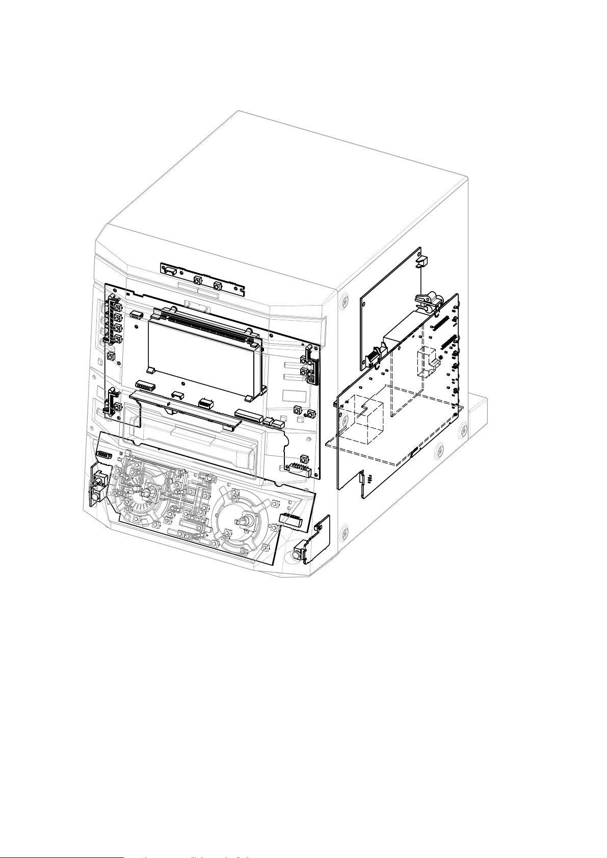
1-2
Location of Printed Circuit Boards
DESIGN FRONT BOARD
LED BOARD
FRONT BOARD
CDC KEY BOARD
MAINS BOARD
TUNER BOARD
AF7 BOARD
HEADPHONE BOARD
MIC. BOARD
DIG. SWITCH
BOARD
Location of PCB R8 2000 02 14

2-1
General:
Mains voltage : 120 / 240V switchable (for /21)
: 230V (for /22)
: 120V (for /37)
Mains frequency : 50 ~ 60Hz
Power consumption : 155W at 1/8 P
RATED
: 350W at max output
: ≤15W at Stand by
: ≤2W at ECO Stand by
Tuner:
FM
Tuning range : 87.5MHz - 108MHz
Grid : 100kHz
IF : 10.7MHz
Aerial input : 75Ω
Sensitivity Mono : < 7µV (26dB S/N)
d (RF=1mV,∆f=75kHz) : 3% - typ. 2%
IF rejection : > 60dB
Image rejection : > 25dB
-3dB Limiting Point : < 23.5dBf
MW
Tuning range : 531kHz - 1062kHz
Grid : 9kHz
IF : 450kHz ±1kHz
Sensitivity at 26dB S/N : < 4.0mV/m
d (RF=50mV,m=80%) : < 5% - typ. 3%
IF rejection : > 45dB
Image rejection : > 28dB
Amplifier:
Output power : 2 x 100W at 6Ω
Headphone : 3.5mm stereo jack
Frequency response : 20Hz - 20kHz (-3dB) Limit
Equalizer : Digital Sound Control
Input sensitivity
Aux/Line : 500mV ±2dB
Microphone : 2.5mV ±2dB at 1kHz
CDC unit:
Frequency response within : 20Hz - 20kHz at ±3dB
Signal/Noise ratio : > 94dB (A-weighted)
Distortion at 1kHz,0dB : -90dB
Channel unbalance : < 0.3dB
Channel crosstalk at 1kHz : -60dB
De-emphasis : 0 or 15/50 µS
Laser
Output power : ≤500µW
Wave length : 780nm ±20nm
CDR unit:
CD Playback:
Frequency response within : 20Hz - 20kHz at ±3dB
Signal/Noise ratio : > 90dB (A-weighted)
Distortion at 1kHz,0dB : -80dB
Channel unbalance : < 1dB
Channel crosstalk at 1kHz : -60dB
De-emphasis : 0 or 15/50 µS
Analog recording - digital playback:
Frequency response within : 20Hz - 20kHz at ±3dB
Signal/Noise ratio : > 84dB (A-weighted)
Distortion at 1kHz,0dB : -77dB
Channel unbalance : < 1dB
Channel crosstalk at 1kHz : -60dB
De-emphasis : 0 or 15/50 µS
Laser
Output power : ≤1mW during reading
: ≤20mW during writing
Laser class 3B
Wave length : 780nm ±20nm
Technical Specification

2-2
Measurement Setup
Bandpass
250Hz-15kHz
e.g. 7122 707 48001
LF Voltmeter
e.g. PM2534
DUT
RF Generator
e.g. PM5326
S/N and distortion meter
e.g. Sound Technology ST1700B
Tuner SW
To avoid atmospheric interference all AM-measurements have to be carried out in a Faraday´s cage.
Use a bandpass filter (or at least a high pass filter with 250Hz) to eliminate hum (50Hz, 100Hz).
Ri=50Ω
Aerial replacement
Capacitor
R=50Ω
Bandpass
250Hz-15kHz
e.g. 7122 707 48001
LF Voltmeter
e.g. PM2534
DUT
S/N and distortion meter
e.g. Sound Technology ST1700B
Frame aerial
e.g. 7122 707 89001
Tuner AM (MW,LW)
To avoid atmospheric interference all AM-measurements have to be carried out in a Faraday´s cage.
RF Generator
e.g. PM5326
Ri=50Ω
Low pass filter 22kHz
L
R
LEVEL METER
e.g. Sennheiser UPM550
S/N and distortion meter
e.g. Sound Technology ST1700B
DUT
CD
Use Audio Signal Disc SBC429 4822 397 30184 (replaces test disc 3)
L.P.F. = 13
th
order filter 4822 395 30204

2-3
RC5 Codes
Remote control key
ALARM
SLEEP
BRIGHTNESS
REPEAT
SHUFFLE
TRACK INCREMENT
VOLUME +
VOLUME -
3
8
w
∑
1
CD, CDR MODE
1
AUX, TUNER MODE
¡
CD, CDR MODE
¡
AUX, TUNER MODE
7
INCREDIBLE SURROUND
PURE
LOUDNESS
BALANCE L
BALANCE R
System Code
16
16
16
20, 26
20, 26
26
16
16
20, 26
20, 26
17,20, 21, 26
17,20, 21, 26
20, 26
17, 21
20, 26
17, 21
20, 26
16
16
16
16
16
Command Code
89
38
71
29
28
114
16
17
53
48
33
32
50
31
52
30
54
64
52
50
27
26
Remote control key
Standby
CD1
CD2
CD3
CDR
Tuner
Aux
1(ABC)
2 (DEF)
3 (GHI)
4 (JKL)
5 (MN)
6 (OPQ)
7 (RST)
8 (UVW)
9 (XYZ)
0 (Space)
YES
NO
EDIT (TEXT)
PROGRAM
PROGRAM
TUNER MODE
MUTE
System Code
17,20, 21, 26
20
20
20
26
17
21
17,20, 21, 26
17,20, 21, 26
17,20, 21, 26
17,20, 21, 26
17,20, 21, 26
17,20, 21, 26
17,20, 21, 26
17,20, 21, 26
17,20, 21, 26
17,20, 21, 26
17,20, 21, 26
17,20, 21, 26
17,20, 21, 26
20, 26
17
16
Command Code
12
55
56
57
63
63
63
01
02
03
04
05
06
07
08
09
00
87
49
82
36
122
13
2-4
Brief Operating Instructions
F
M
A
E
R
IA
L
3
0
0
Ω
A
M
A
E
R
I
A
L
R
L
C
D
C
H
A
N
G
E
O
P
E
N
/C
LO
S
E
CD REW
RIT
ABLE COM
P
A
TIBLE • 3 CD CHA
NG
ER
D
IS
P
L
A
Y
C
D
R
iR SENSOR
TU
NER
D
I
G
I
T
A
L
/
A
N
A
L
O
G
A
U
X
CD TEXT
CLOCK/TIMER
O
P
E
N
/
C
L
O
S
E
M
I
C
MIC
LEVEL
12
5670!@#$%^
0&
( ) ¡ £ ≤ ∞ §
89
34
*
C
D
-
T
E
X
T
E
D
I
T
I
N
G
STANDBY
ON
CD
1
CD 2
CD 3
R
E
C
T
Y
P
E
E
D
I
T
COMPILE CD
FINALIZE
E
R
A
S
E
CD
CD
RECORD
FW-
R8
CD RECORDABLE
M
I
N
I
H
I
F
I
S
Y
S
T
E
M
L
A
C
M
A
IN
S
~
S
P
E
A
K
E
R
S
6
Ω
D
I
G
I
T
A
L
O
U
T
D
I
G
I
T
A
L
I
N
L
R
LINE
OUT
AUX
IN
R
SUBWOOFER
OUT
DC
C
H
A
N
G
E
R
≥
•
º
™
ª
C
D
REC
O
RD
ER
English
recordings
menu
and automatic finalizing of
current CD
and automatic finalizing of
current program
settings on/off
stereo effect
CD recorder tray
information
activates and deactivates the
timer
remote control
7
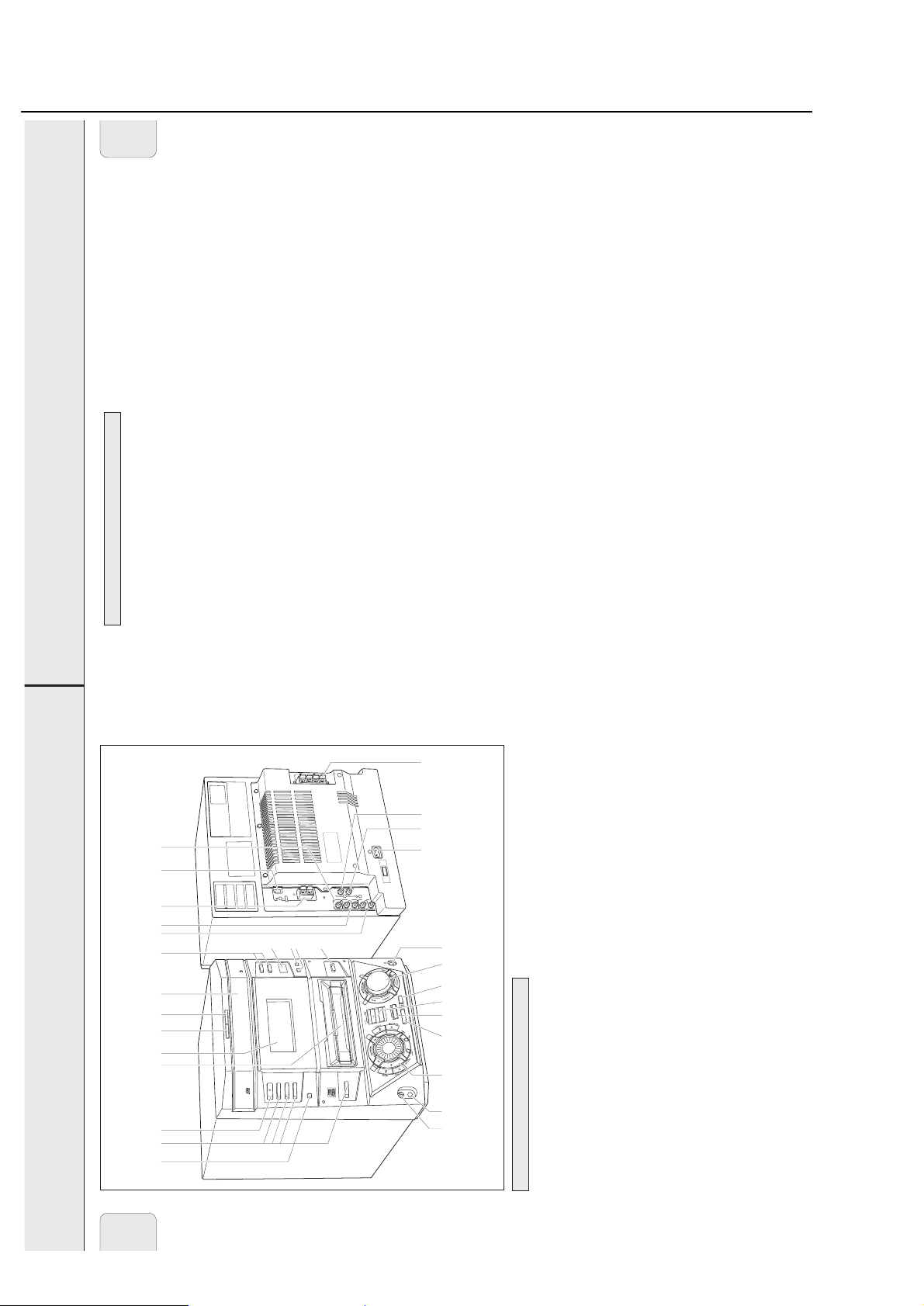
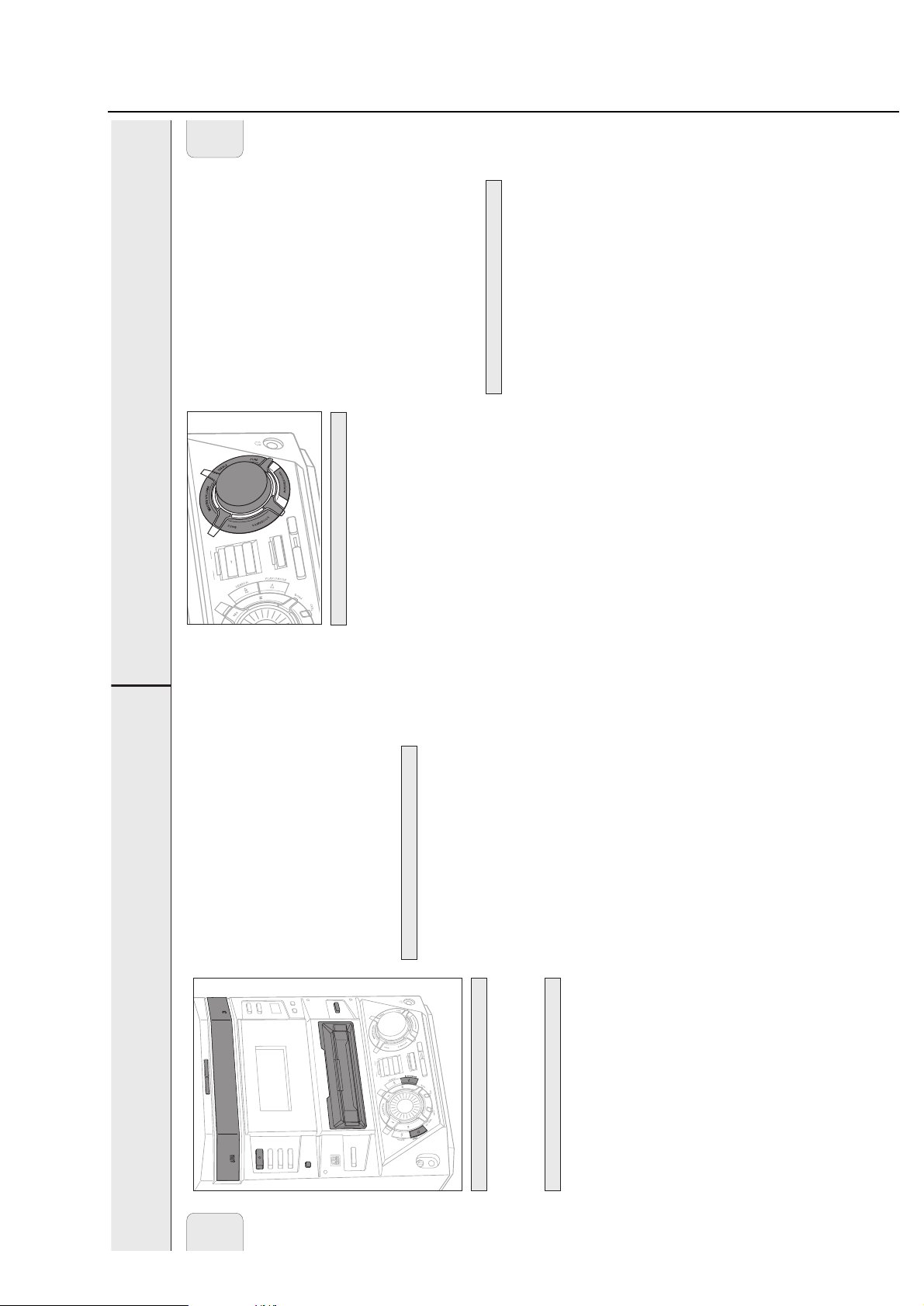
CONTROLS AND CONNECTIONS
¡ FINALIZE...............................finalizes and unfinalizes
On the front
0 Source selection
CD™CD..................................selects high speed recording
™ REC TYPE..............................enters/exits the recording
switches to CD 1, CD 2 or
CD 3
CD 1, CD 2, CD 3 ..................selects the CD changer,
COMPILE CD........................selects high speed recording
£ RECORD
additional appliance
CDR........................................selects the CD recorder
TUNER...................................selects the tuner
DIGITAL / ANALOG AUX....selects the input for an
≤ ERASE ...................................erases recordings
CD changer tray
! ...............................................CD changer tray
@ OPEN/CLOSE........................opens and closes the
# CD CHANGE .........................selects the next disc tray
MASTER VOLUME ..............adjusts the volume
TREBLE .................................sets the treble level
PURE .....................................switches bass and treble
∞ Sound control
$ ...............................................display
INCREDIBLE SURR..............creates an incredibly wide
standby
information/text
% CD RECORDER .....................CD recorder tray
^ y STANDBY ON...................switches the unit on and to
& DISPLAY ...............................selects display
Note: Connecting the headphones will switch off the
LOUDNESS...........................boosts treble and bass
BASS.....................................sets the bass level
§ p ...........................................3.5 mm headphone jack
volume
Rotary control:
* MIC LEVEL ...........................adjusts the microphone
( MIC ........................................microphone jack
) Multiple function control
speakers.
≥ OPEN/CLOSE........................opens and closes the
• CD TEXT................................switches through CD text
ª CLOCK/TIMER ......................selects the clock function,
º iR SENSOR ...........................sensor for the infrared
previous/next track
TUNER: selects the
previous/next preset tuner
station
reviews the tracks in a
í JOG CONTROL ë........CDC, CDR: selects the
Keys to press:
YES ........................................confirms a selection
á SEARCH..........................CDC, CDR: searches forward,
selection.
to facilitate the finding of the relevant keys for
programs you are in. This is for your guidance in order
on the unit depending on the different modes or
Note: You will recognize that various keys will be illuminated
program, controls the cursor
in different menus
TUNER: tunes to a higher
radio frequency
playback/recording
menu
menu
menu
adjust the level for
É PLAY/PAUSE..................starts and interrupts
PROG.....................................opens/closes the program
EDIT TEXT.............................enters/exits the text edit
EDIT TRACK .........................enters/exits the track edit
REC LEVEL............................enables the rotary control to
recordings
program memory
backward, reviews the tracks
in a program, controls the
cursor in different menus
Ç STOP...............................stops CD play/record, closes
à SEARCH..........................CDC, CDR: searches
TUNER: tunes to a lower
radio frequency
NO..........................................cancels a selection
CONTROLS AND CONNECTIONS
English
antenna here
antenna here
output of an additional
appliance
input of an additional
appliance
6 AM AERIAL ..........................connect the supplied loop
7 FM AERIAL 300 Ω ...............connect the supplied wire
8 AUX IN L/R ...........................connect to the analog audio
9 LINE OUT L/R .......................connect to the analog audio
, connect the power
made
power cable.
cord to the power outlet.
connections have been
After all other
On the back
1 AC MAINS ~ ........................
use only the original
For optimal performance
of a digital appliance
of a digital appliance
2 DIGITAL IN ...........................connect to the coaxial output
3 DIGITAL OUT........................connect to the coaxial input
4 SPEAKERS 6 Ω L/R .............connect to the supplied
speakers
subwoofer
5 SUBWOOFER OUT ..............connect to the input of a
6

2-5
Brief Operating Instructions
INSTALLATION
9
AUX IN L/R
It is possible to use an additional appliance, e.g. tape
recorder, TV or VCR, with the unit.
1 Insert the red plug of a cinch cable to the red jack AUX IN R
and insert the white plug to the white jack AUX IN L.
2 Connect the other end of the cinch cable to the audio
outputs of the additional appliance.
3 Press DIGITAL / ANALOG AUX repeatedly to select the
analog input for the appliance.
yAUX Analog is displayed.
4 Operate your appliance as usual and adjust volume and
sound with the unit.
Note: It is not possible to connect a turntable directly to
AUX IN L/R.
If you wish to use a turntable with the
unit, you have to connect an amplifier to
AUX IN L/R
on
the unit. Then connect the turntable to the amplifier.
LINE OUT L/R
You can use these outputs for playback or recording on any
analog audio equipment e.g. amplifier or tape recorder.
• Use a cinch cable to connect the analog audio inputs of the
additional appliance with LINE OUT L/R on the unit and
operate your appliance as usual.
DIGITAL IN
You can use this coaxial input for recordings from any digital
audio equipment with a digital coaxial output e.g. CD player
or DVD player.
1 Use a coaxial cable to connect the coaxial output of the
additional appliance with DIGITAL IN on the unit.
2 Press DIGITAL / ANALOG AUX repeatedly to select the
digital input for the appliance.
yAUX Digital is displayed.
3 Operate your appliance as usual.
DIGITAL OUT
You can use this coaxial output for recordings on any digital
audio equipment with a digital coaxial input e.g. CD recorder.
• Use a coaxial cable to connect the coaxial input of the
additional appliance with DIGITAL OUT on the unit and
operate your appliance as usual.
A subwoofer can be used to enhance the bass performance of
your unit dramatically.
1 Use a cinch cable to connect the input of the subwoofer
with SUBWOOFER OUT at the unit.
2 Follow the instructions supplied with the subwoofer.
Connecting a subwoofer
Digital audio connectionsAnalog audio connections
English
L
R
SPEAKERS 6Ω
OUT
DIGITAL
Ω
AM
300
AERIAL
FM AERIAL
OUT
SUBWOOFER
CD RECORDER
~
AC MAINS
IN
DIGITAL
LINE
OUT
AUX
IN
L
L
R
R
CD PLAYER
SUBWOOFER
Antenna connections
below.
AM antenna
The supplied loop antenna is for indoor use only.
1 Fit the plug of the loop antenna to AM AERIAL as shown
2 Position the antenna as far as possible from a TV, VCR or
L
M
IA
A
R
E
A
other radiation sources.
3 Turn the antenna for optimum reception.
TAPE RECORDER
FM antenna
The supplied wire antenna can only be used to receive nearby
down as shown below.
stations. For better reception we recommend using a cable
antenna system or an outdoor antenna.
1 Open the FM AERIAL 300 Ω click-fits by pushing the lever
2 Insert each wire of the antenna into one hole.
reception.
3 Close the click-fits using the lever.
4 Move the antenna in different positions for optimum
L
Ω
IA
0
R
0
E
3
A
M
F
L
Ω
IA
0
R
0
E
3
A
M
F
21 CFR 1040.10. Operation is subject to the following
The unit complies with the FCC-Rules, Part 15 and with
operation.
including interference that may cause undesired
2. This device must accept any interference received,
1. This device may not cause harmful interference, and
two conditions:
INSTALLATION
switching on the power supply.
Make sure all connections have been made before
plate corresponds to your local power voltage. If it does
Power
not, consult your dealer or service organization.
The type plate is located on the rear of the unit.
1 Check whether the power voltage as shown on the type
the power outlet. This switches on the power supply.
2
3 Connect the supplied power cable to AC MAINS ~ and to
English
cable.
For optimal performance use only the original power
When the unit is switched to standby, it is still consuming
some power. To disconnect the unit from the power
under extreme conditions. If this happens, switch the
been built in. Therefore, your unit may disconnect
completely, remove the power cable from the power outlet.
To avoid overheating of the unit, a safety circuit has
Speaker connections
unit off and let it cool down before reusing it.
The speaker connections are click-fit connectors. Use them as
shown below.
and the black (or unmarked) wire to the black terminal.
– Left speaker to L (red and black)
1 Connect the colored (or marked) wire to the red terminal
– Right speaker to R (red and black)
2 Connect:
8
2-6
Brief Operating Instructions
CDR
CD3CD1TUNER CD2
TEXT
ABC DEF GHI
JKL MN OPQ
RST UVW XYZ
SPACE
AUX
EDIT
VOLUME
NO YES
PROGRAM TRACK INCR.SHUFFLE REPEAT
TIMER ON/OFF SLEEP MUTE
BRIGHTNESS BALANCE
LOUDNESS INCREDIBLE PURE
SURROUND
LR
+
-
É
Ç
ë
0
8
5
2
9
6
3
7
4
1
2
ë
Å
AM
PM
TIME
TRACKPRESET STEP TOTAL TRACK TIME
CD TEXT EDIT TRACK
TUNER
REC
PROG ALARM SLEEP
REPEAT SHUFFLE
DISC TRACK ALL
CD RECORDER
COMPILE CDC
FM TUNER
CD CD AUX
START
FINALIZE
MIC
ALC
FINISH
CD R W
RECORDING IN PROGRESS
AUX
STEREO
NEWS TA
EON
DIGITAL ANALOG
20 4321
+
1098765
1514131211
19181716
CD CHANGER
CD R W
INCREDIBLE
SURROUND
LOUDNESS
PURE
AM
PM
TIME
TRACKTOTAL RECREMPRESET STEP TOTAL TRACK TIME
TUNER
CD RECORDER
COMPILE CDC
FM TUNER
CD CD AUX
START
FINALIZE
MIC
ALC
FINISH
CD R W
RECORDING IN PROGRESS
AUX
STEREO
DIGITAL ANALOG
20 4321
+
1098765
1514131211
19181716
CD CHANGER
CD R W
INCREDIBLE
SURROUND
LOUDNESS
PURE
English
DISPLAY
high speed dubbing and auto finalize
high speed dubbing and auto finalize
CD Recorder
COMPILE CDC .....current program is being recorded with
Display
The display of the unit is divided into 3 sections, which show
being recorded
.....status of recording progress is shown
............current disc is being recorded with
É .........................playback is activated
Å .........................playback is interrupted
PM
PM
AM
AM
EON
NEWS TA
TUNER
TUNER
STEREO
STEREO
MIC
MIC
FINALIZE
FINALIZE
CD R W
CD R W
CD RECORDER
CD RECORDER
FM TUNER
FM TUNER
COMPILE CDC
COMPILE CDC
CD R W
CD R W
CD CHANGER
CD CHANGER
START FINISH
RECORDING IN PROGRESS ..recording in progress
CD..................................pre-recorded CD, finalized CDR or
1098765
1514131211
19181716
1098765
1514131211
19181716
AUX
AUX
DIGITAL ANALOG
DIGITAL ANALOG
+
+
20 4321
20 4321
PURE
PURE
LOUDNESS
LOUDNESS
SURROUND
SURROUND
INCREDIBLE
INCREDIBLE
FINISH
FINISH
ALC
ALC
RECORDING IN PROGRESS
RECORDING IN PROGRESS
START
START
CD CD AUX
CD CD AUX
REC
CD TEXT EDIT TRACK
PROG ALARM SLEEP
DISC TRACK ALL
REPEAT SHUFFLE
FM TUNER ..........FM station is being recorded
CD=CD
AUX ...................material from an external source is
TIME
TIME
TRACKTOTALRECREMPRESET STEP TOTAL TRACK TIME
TRACKTOTAL RECREMPRESET STEP TOTAL TRACK TIME
you the following:
Information area
CDRW inserted
CD R ...............................unfinalized CDR inserted
CD RW ............................unfinalized CDRW inserted
FINALIZE .........................(un)finalizing will start
MIC ................................microphone input is being used
ALC ................................auto level control is active
Tuner
STEREO...........................FM station is being received in stereo
AUX
DIGITAL...........................digital input in use for external source
ANALOG..........................analog input in use for external source
Music calendar, sound lights and remote control
1098765
1514131211
19181716
1098765
1514131211
EON
AUX
AUX
NEWS TA
DIGITAL ANALOG
DIGITAL ANALOG
PURE
PURE
STEREO
STEREO
LOUDNESS
LOUDNESS
SURROUND
SURROUND
INCREDIBLE
INCREDIBLE
FINISH
FINISH
MIC
MIC
ALC
ALC
FINALIZE
FINALIZE
CD R W
CD R W
RECORDING IN PROGRESS
RECORDING IN PROGRESS
FM TUNER
FM TUNER
START
START
COMPILE CDC
COMPILE CDC
CD CD AUX
CD CD AUX
CD R W
CD R W
+
+
20 4321
20 4321
REC
CD TEXT EDIT TRACK
PROG ALARM SLEEP
REPEAT SHUFFLE
19181716
DISC TRACK ALL
PM
PM
AM
AM
TIME
TIME
TUNER
TUNER
TRACKPRESET STEP TOTAL TRACK TIME
TRACKTOTAL RECREMPRESET STEP TOTAL TRACK TIME
CD RECORDER
CD RECORDER
CD CHANGER
CD CHANGER
This area is used for feedback of the CD changer, CD recorder,
tuner frequencies, menu options, values and scrolling text
messages.
Status lights and flags
INCREDIBLE SURROUND....Incredible Surround is active
LOUDNESS ......................Loudness is active
Flags
CD TEXT ..........................CD text is available
CD TEXT EDIT ..................text edit menu is active
EDIT TRACK ....................track edit menu is active
REC X ..........................record timer is selected
PROG..............................program menu is active
ALARM X .....................alarm timer is selected
SLEEP .............................sleep timer is selected
X ................................clock is selected
off
received
number of tracks on a disc/program
TUNER: preset number of tuned
station
more than 20 tracks
TUNER: more than 20 radio stations
are stored
......spectrum analyzer
...............................command from remote control is being
PURE ..............................bass and treble settings are switched
REPEAT DISC ...................selected disc is played repeatedly
REPEAT TRACK.................current track is played repeatedly
1–20..........................CDC, CDR: actual track number played,
Music calendar
program) are (is) played repeatedly
the loaded disc(s) in the CD changer or
REPEAT ALL .....................all discs in the CD changer (or the
SHUFFLE..........................either all tracks of the program or of
+................................CDC, CDR: disc or program contains
CD recorder are played in random
order
........................number of disc trays loaded
É........................playback is activated
CD Changer
Å .........................playback is interrupted
CD 1, 2, 3 .....................disc tray 1, 2 or 3 is selected and
loaded with a pre-recorded CD,
finalized CDR or CDRW
11
loaded with an unfinalized CDR
loaded with an unfinalized CDRW
CD R 1, 2, 3..................disc tray 1, 2 or 3 is selected and
CD RW 1, 2, 3...............disc tray 1, 2 or 3 is selected and
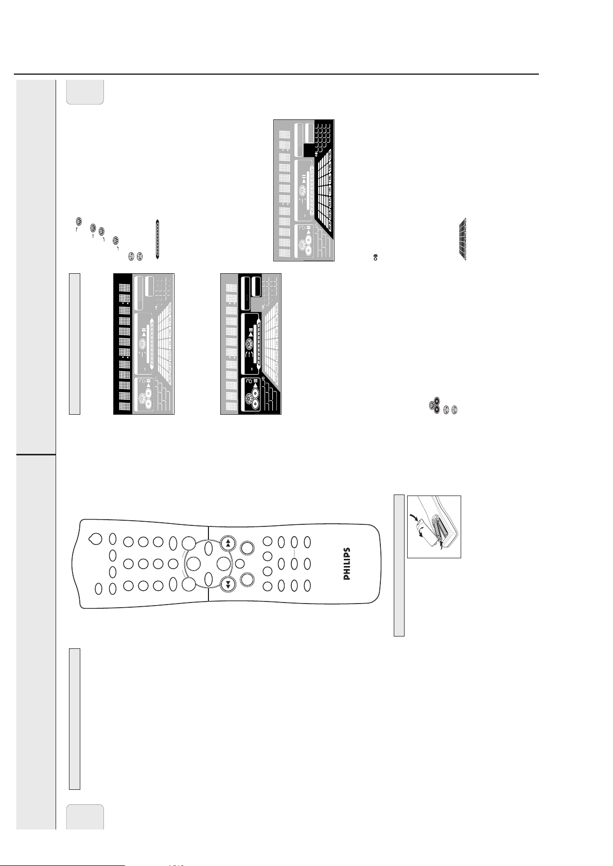
Remote control batteries
Open the battery compartment
of the remote control and insert
2 alkaline batteries, type AA
(R06, UM-3).
Do not use old and new or
different types of batteries in
combination.
Remove batteries if they are dead or if the remote control is
not to be used for a long time.
be disposed of properly.
Batteries contain chemical substances, so they should
REMOTE CONTROL
Remote control buttons
2 ...........................switches the unit to standby
CDR, TUNER, CD1,
CD2, CD3, AUX........selects the sources
Number/alphabet keys
English
TUNER: selects the previous preset tuner
1–0....................keys in numbers for tracks or stations
ABC – XYZ ........keys in letters for text
SPACE ...............keys in a space within the text
EDIT TEXT................enters the text edit menu
-VOLUME.............decreases the volume
+VOLUME.............increases the volume
É ...........................starts playback/recording
í ..........................CDC, CDR: selects the previous track
station
TUNER: selects the next preset tuner
station
memory
tracks in a program, controls the cursor in
ë ...........................CDC, CDR: selects the next track
Ç ...........................stops CD play/recording, closes program
á ...........................CDC, CDR: searches forward, reviews the
different menus
TUNER: tunes to a higher radio frequency
the tracks in a program, controls the
cursor in different menus
TUNER: tunes to a lower radio frequency
à ...........................CDC, CDR: searches backward, reviews
Å ...........................interrupts playback/recording
YES ..........................selects a selection
NO ...........................cancels a selection
PROGRAM ...............opens/closes the program menu
SHUFFLE ..................plays tracks in random order
program
a track
REPEAT....................repeats a track, the entire CD(RW) or the
TRACK INCR............selects automatic or manual increment of
TIMER ON/OFF........activates and deactivates the timer
SLEEP.......................activates the sleep timer
speaker
MUTE.......................mutes the sound
BRIGHTNESS...........controls the brightness of the display
L BALANCE..............adjusts the volume balance to the left
R BALANCE .............adjusts the volume balance to the right
speaker
) before selecting the desired function
CD1
control (e.g.
LOUDNESS ..............boosts treble and bass
INCREDIBLE
SURROUND .............creates an incredibly wide stereo effect
PURE........................switches bass and treble settings on/off
Note: Always press the source key of the source you wish to
SHUFFLE).
key (e.g.
10
2-7
Brief Operating Instructions
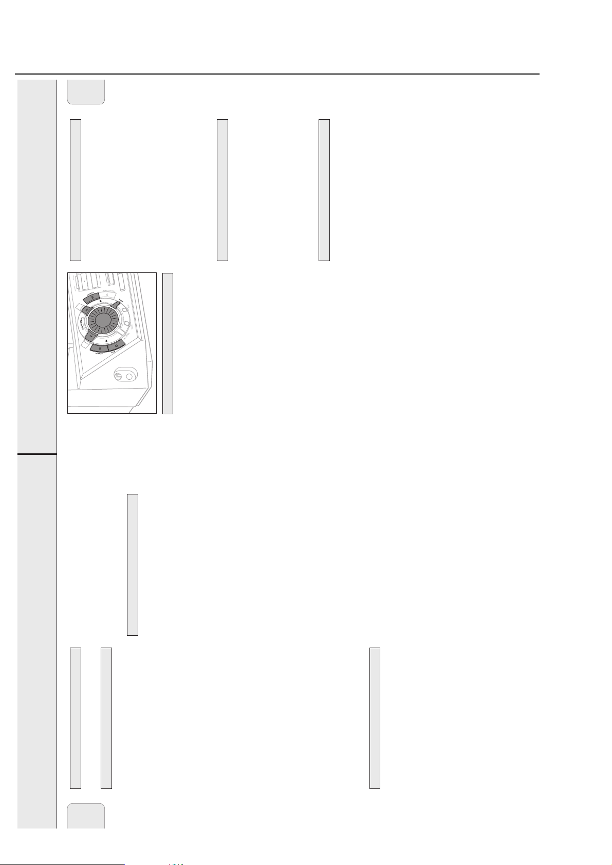
BASIC FUNCTIONS
13
Volume adjustment
• Adjust the volume by using MASTER VOLUME
(-VOLUME/+on the remote control).
yThe volume level in dB (decibel) is displayed.
Incredible Surround
Stereo sound is determined by the distance between the front
speakers. Incredible Surround enables you to enjoy an incredibly
wide stereo effect, regardless of the speakers’ distance.
• Press INCREDIBLE SURR. (INCREDIBLE SURROUND on the
remote control) to switch the surround sound effect either
on or off.
y
INCREDIBLE SURROUND
is shown and Incredible
Surround is displayed if the surround sound effect is on.
Note: The effect of Incredible Surround may vary with different
types of music.
Treble and Bass level adjustment
1 Press TREBLE or BASS on the unit.
yThe volume rotary is activated to select the treble/bass
settings.
2 Turn the volume rotary to adjust the treble or bass.
yTreble or Bass and the actual value (between –5
and +5) is displayed briefly.
Note: If the volume rotary is not turned for 5 seconds, it will
switch back to volume.
PURE
• Press PURE repeatedly to switch bass and treble settings
either on or off.
yPURE is shown and Pure is displayed if bass and treble
settings are switched off.
yOptimal is displayed if preset bass and treble
settings are switched on.
yPersonal is displayed if personal preset bass and
treble settings are switched on.
LOUDNESS
• Press LOUDNESS to switch loudness either on or off.
yLOUDNESS is shown and Loudness is displayed if
loudness is on.
MUTE
This feature allows you to temporarily switch off the sound
without switching off the unit.
1 Press MUTE on the remote control to switch off the sound.
yMute is displayed and playback/recording will be
continued without sound.
2 Press MUTE on the remote control again to switch on the
sound again.
Speaker balance
It is possible to adjust the relative volume balance between
the connected front speakers.
• Press L BALANCE or R BALANCE on the remote control to
adjust the relative volume of the left or right front speaker.
yBalance L (or R) and the actual volume of the left
(or right) front speaker are displayed.
yWhen the volume of both speakers is balanced,
Balance L=R is displayed.
The demo mode displays various features of the unit and will
start automatically.
•
If any source key is pressed:
yThe unit switches to the selected source.
If
y STANDBY ON
is pressed:
yThe unit switches to standby. After a few seconds, the
demonstration will start again.
Cancelling the demo mode
• Keep Ç STOP on the unit pressed for at least 3 seconds to
cancel the demo mode.
yThe demo mode is cancelled permanently. The unit
switches to standby. A few seconds later the unit
switches to an economy power save mode.
Demo mode
Sound control
English
CD
D
R
O
C
CD
E
R
CD changer:
Press OPEN/CLOSE on the unit again to close the tray.
yThe tray is closed and Reading is displayed.
yIf an unfinalized disc is inserted, Initializing will
3
E
S
RA
E
E
P
Y
T
C
E
R
PILE CD
COM
ALIZE
FIN
be displayed.
the total playing time of the disc in the last selected disc
tray are displayed. The track numbers light up in the music
calendar.
yCD, the disc tray number, the total number of tracks and
CD recorder:
Press OPEN/CLOSE on the unit again to close the tray.
yThe tray is closed and Reading is displayed.
yIf an unfinalized disc is inserted, Initializing will
be displayed.
of the disc are displayed. The track numbers light up in the
music calendar.
yCDR, the total number of tracks and the total playing time
elapsed playing time are displayed. The current track
number is also blinking in the music calendar.
playback.
CD changer:
Playing a CD(RW)
yCD, the disc tray number, the current track number and
1 Press É PLAY/PAUSE (Éon the remote control) to start
are displayed. The current track number is also blinking
in the music calendar.
CD recorder:
yCDR, the current track number and elapsed playing time
press DISPLAY on the unit:
yTrack number, remaining playing time of current track
yTrack number, remaining playing time of disc
yTrack number, actual playing time of current track
CD changer:
• To switch through the following information, repeatedly
yCD, the disc tray number, the total number of tracks and
2 Press Ç STOP (Çon the remote control) to stop playback.
the total playing time of the disc are displayed.
time of the disc are displayed.
CD recorder:
press DISPLAY on the unit:
yCDR, the total number of tracks and the total playing
• To switch through the following information, repeatedly
(Åon the remote control).
yTotal number of tracks, total playing time of disc
yCD text is displayed.
yThe time where playback was interrupted is blinking.
• You can interrupt playback by pressing É PLAY/PAUSE
remote control) again.
• To resume playback press É PLAY/PAUSE (Éon the
BASIC FUNCTIONS
ER
G
DC
N
A
H
C
R
OPEN/CLOSE
E
G
N
A
H
C
D
C
3
•
E
L
B
I
T
A
P
M
O
C
E
L
B
A
T
I
R
W
E
R
D
C
CD CHANGE
English
R
E
M
I
T
/
K
G
C
R
O
O
L
O
L
A
S
C
N
N
/ A
E
T
L
S
A
R
IT
i
IG
D
R
X
E
U
N
A
U
T
1
CD
CD 3
STANDBY
ON
CD 2
E
S
O
L
C
/
N
X
E
E
T
P
D
O
C
MINI HIFI SYSTEM
E
L
B
A
D
R
O
TEXT EDITING
C
-
E
R
CD
D
C
R8
FW-
Y
A
L
P
IS
D
D
C
D
R
O
D
C
C
E
R
RECORDER
CD
R
D
C
E
S
A
R
E
D
C
E
REC TYPE
L
I
P
E
M
Z
I
O
L
C
A
N
I
F
T
I
D
E
L
E
IC
V
E
M
L
C
I
M
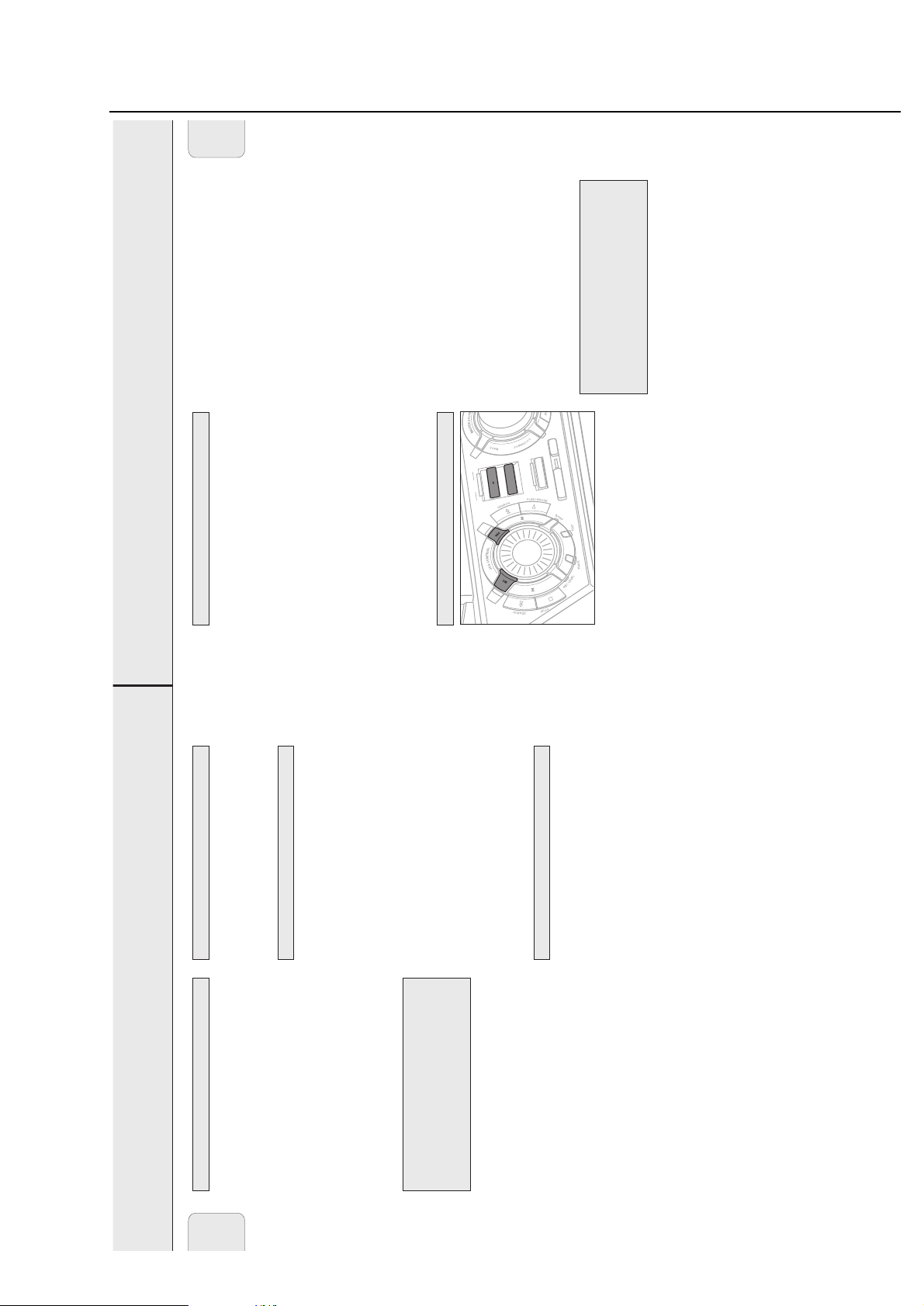
Switching on, switching to standby
• To switch the unit on press y STANDBY ON on the unit.
the changer mechanism.
on the market, because they may cause jamming of
stabilizer rings or CD treatment sheets, etc. as offered
again on the unit (2 on the remote control).
• To switch the unit to standby press y STANDBY ON
Therefore, do not use any accessories such as disc
Loading the CD changer, CD recorder
Important!
1) This system is designed for regular CD(RW)s.
CD changer:
Press OPEN/CLOSE on the unit to open the CD changer tray.
2) Do not load more than one disc into one disc tray.
1
Insert an
audio disc (printed side up) in the right disc tray.
• You can load another disc in the left disc tray.
continuous playback without interruption.
yOpen CDC is displayed and the tray is opened.
CD recorder:
You can load up to three discs in the CD changer for
Press OPEN/CLOSE on the unit to open the CD recorder tray.
yOpen CDR is displayed and the tray is opened.
CD changer:
2
is at the right hand side.
yThe CD carousel will rotate until the empty disc tray
• To insert a third audio disc, press CD CHANGE on the unit.
CD recorder:
Insert an audio disc (printed side up) in the tray.
12
2-8
Brief Operating Instructions
PE
English
PROGRAM
15
program time are displayed.
control) to stop playback.
Erasing a track from the program
D
C
D
C
RECORD
memory.
1 If necessary, press Ç STOP on the unit (Ç on the remote
2 Press either CD 1, CD 2, CD 3, or CDR to select the desired
D
C
E
REC TY
IL
P
E
M
IZ
O
L
C
A
IN
F
L
E
IC
V
E
M
L
yThe track number at the selected step and the total
à SEARCH or á SEARCH (à or á on the remote
control) to move through the program steps.
3 Press PROG (PROGRAM on the remote control), followed by
IT
D
E
IC
M
position and is displayed together with the step number
and the remaining total program time.
yCleared is displayed briefly.
yThe next programmed track number will move up to this
4 Press NO to remove the track from the program.
Programming track numbers
You can select tracks and store them either in the CD changer
or CD recorder memory. If you use the program for playback
you can choose one of the two memories, else if you like to
specify tracks for recording, use the CD changer memory only!
You can store any track more than once.
control) to stop playback.
Clearing the program
1 Load the desired disc(s) in the disc tray(s).
yClear Prog? is displayed.
1 If necessary, press Ç STOP on the unit (Ç on the remote
2 Press NO.
yPROG starts blinking and Program is displayed.
2 Press either CD 1, CD 2, CD 3, or CDR to select the disc.
3 Press PROG on the unit (PROGRAM on the remote control).
tray the respective program will be cleared.
yProg Cleared will be displayed and PROG goes off.
3 Press YES to clear the program.
Note: When you open the CD recorder tray or the CD changer
programmed.
If either CD 1, CD 2 or CD 3 is selected:
Rotate í JOG CONTROL ë to select either:
yCD1 (or 2, 3) All: All tracks of CD 1 (or 2, 3) will be
yCD1 (or 2, 3) and track number: The track number of
4
memory (see “Programming track numbers”).
Making a program for recording
1 Select and store all desired tracks in the CD changer
2 Enter the recording menu (see “Internal recording”).
CD 1 (or 2, 3) will be programmed.
If CDR is selected:
Rotate í JOG CONTROL ë (press the numerical keys on
the remote control; for 2-digit numbers, press the keys in
rapid succession) to select a track number.
5 Press YES to store your selection in the memory.
the time of the program start blinking. Now you can
change the program (see “Programming track numbers”,
“Erasing a track from the program” and “Clearing the
the remaining recording time and Record Prog?
yNot fitting! will be displayed briefly, followed by
remaining recording time of the CDR(W):
If you nevertheless start recording, only those tracks of the
program that fit onto the CDR(W) will be recorded in
• If the total time of the program is of larger size than the
entirety.
•To change the program, press NO.
yEdit Program will be displayed briefly, PROG and
program”).
Program full.
total program time are displayed. The track number
yThe number of programmed tracks (STEP), Prog and the
blinks in the music calendar.
to end programming.
6 Select and store all desired tracks in this way.
7 Press PROG on the unit (PROGRAM on the remote control)
reached, the display shows
available.
yPROG stays shown and the program is currently
Note: If the maximum number of programmable tracks is
of the loaded disc(s) in the CD changer or CD recorder
are played in random order.
ySHUFFLE is shown and either all tracks of the program or
Playing tracks in random order
1 Press SHUFFLE on the remote control during playback.
Selecting a disc on the CD changer
BASIC FUNCTIONS
• Press either CD 1, CD 2 or CD 3 to select a particular disc.
English
CD text
2 To return to normal playback, press SHUFFLE again.
remote control) to skip to the required track number.
yPlayback continues with the selected track.
control) to skip to the beginning of the previous or next track
Selecting a track and searching
on the selected disc.
Selecting a track during playback
• Rotate í JOG CONTROL ë (pressí or ë on the remote
Selecting a track when playback is stopped
playback.
1 Rotate í JOG CONTROL ë (pressí or ë on the
2 PressÉ PLAY/PAUSE (Éon the remote control) to start
yPlayback starts with the selected track.
on the remote control, you can
ë
or
í
rapid succession.
numerical keys. For 2-digit numbers, press the keys in
also directly key in the required track number by using the
Note: Instead of using
Searching for a passage during playback
volume. After 3 seconds, the search speeds up with
volume muted.
ySearching is started and playback continues at a low
control) pressed to find a particular passage in a backward
or forward direction.
1 Keep à SEARCH or á SEARCH (à or á on the remote
yNormal playback continues.
2 Release the key at the desired passage.
, while repeating a track or while playing
SHUFFLE
track.
a program, searching is only possible within the current
playback to select either:
Note: During
SHUFFLE and REPEAT
Repeating a track, the disc or the program
1 Repeatedly press REPEAT on the remote control during
are (is) played repeatedly.
yREPEAT TRACK: The current track is played repeatedly.
yREPEAT DISC: The entire selected disc is played repeatedly.
yREPEAT ALL: All discs in the CD changer (or the program)
2 Playback starts in the chosen mode.
or while
SHUFFLE
is not possible during
playing a program.
REPEAT DISC
control until the display indication disappears.
3 To return to normal playback, press REPEAT on the remote
Note:
14
2-9
Brief Operating Instructions
INTERNAL RECORDING
17
For internal recordings you can record from the internal
CD changer or tuner. You can choose from the following
recording modes:
– High speed recording and automatic finalizing:
Fast and easy! Record and finalize your CDR(W) in one
quick step while the sound is muted. You can record the
current CD or a program from the CD changer.
– High speed recording:
Record your CDR(W) fast while the sound is muted. You can
record an entire CD, a track, a program or a track edit from
the CD changer.
– Normal recording and listening:
Listen to the recording while you are making it. You can
record an entire CD, a track, a program or a track edit
from the CD changer.
– Manual recording:
Start and stop your recording manually while listening to
it. You can do either microphone recordings or radio
recordings from the FM tuner.
High speed recording and automatic finalizing of the
current disc
1 Make sure the CDR(W) is absolutely free of scratches and
dust particles.
2 Press CD™CD on the unit to enter the recording mode.
yBoth decks will be selected in the display, the arrow starts
blinking. The remaining recording time of the CDR(W), the
total playing time of the source CD and Record CD1
(or 2, 3)? are displayed.
3 Press YES to start recording and finalizing.
yThe arrow lights, RECORDING IN PROGRESS is shown, high
speed recording and finalizing start, and the actual
recording time remaining starts to count down.
Note: If a program was already available before pressing
CD™CD
, this will be ignored.
PROG
goes off and the
current disc will be recorded. After finishing the recording,
PROG
is shown and the program is available again.
High speed recording and automatic finalizing
(optional) of the current program
1 Make sure the CDR(W) is absolutely free of scratches and
dust particles.
2 Press COMPILE CD on the unit to enter the record mode.
yBoth decks will be selected in the display, the arrow
starts blinking. The remaining recording time of the
CDR(W), the total playing time of the source CD and
Record Prog? are displayed.
3 Press either:
YES to confirm,orNO to change the program.
yPROG starts blinking. Now you can change the program
(see “Program”) and return to the record mode by
pressing COMPILE CD.
4 Auto Fin? is displayed.
Press either:
YES, if the CDR(W) is to be finalized after recording,
or
NO, if the CDR(W) is not to be finalized after recording.
yThe arrow lights, RECORDING IN PROGRESS is shown, high
speed recording and finalizing (if selected) start and the
actual recording time remaining starts to count down.
Note: If no program is available and you press
COMPILE CD
,
you enter immediately into the program menu. Start
your programming and return to the record mode by
pressing
PROGRAM
or
COMPILE CD.
DO NOT FORGET TO FINALIZE!
Finalizing a CDR(W) disc is a simple procedure, necessary to:
– play a recorded CDR on a standard CD player or
– play a recorded CDRW on a CDRW compatible CD player
and CD recorder.
High speed recording and automatic finalizing
Recording modes
English
E
S
A
R
E
E
P
Y
T
D
C
C
E
E
R
IL
D
P
C
D
R
O
D
C
C
E
R
E
M
IZ
O
L
C
A
IN
F
Direct Line Recording (DLR)
The CD recorder is equipped with the high-performance Direct
Line Recording technique. It ensures a perfect recording of
the source material, meaning a true “bit for bit” recording.
Auto Level Control (ALC)
DLR will always become active when you make normal
recordings in listen mode.
Auto Level Control ensures that the tracks on the recorded
ALC is shown.
disc have a similar volume level. At all times the already
recorded tracks of the CDR(W) disc will be taken as reference
for the volume level of the following recordings. ALC is active
when
and the CDR(W) has recordings on it,
CD changer is being high speed recorded, or
– COMPILE CD is being used,
– a disc, a track or a track edit is being high speed recorded
– a program (consisting from more than one disc) from the
Auto level control becomes active when:
on it,
– CD™CD is being used and the CDR(W) has recordings on it.
– CD™CD is being used and the CDR(W) has no recordings
– making recordings from the FM tuner,
Auto level control will not become active when:
EDIT
– making recordings from an external source, or
– making normal recordings in listen mode.
REC LEVEL key
You can adjust the reference record level. This is also possible
when ALC is active. This feature can be used for fading your
recordings in or out.
1 Keep REC LEVEL on the unit pressed to enable the rotary
yThe actual record level (in dB) will be displayed.
control to adjust the record level.
record level.
2 Turn the rotary control to the left to adjust the desired
standby.
• The record level is reset after the unit has been switched to
from a selected external source
– Recording from the internal CD changer and tuner or
Basic information
ABOUT RECORDING
English
– Finalizing your CDR(W) discs and unfinalizing your
The CD recorder deck offers you 3 main functions:
Make sure the CDR(W) is absolutely free of
CDRW discs
– Erasing a CDRW disc
scratches and dust particles.
The recording procedure is the same for CDR and CDRW
discs.
For recordings, the minimum track length is 4 seconds. You can
record up to a maximum of 99 tracks on a disc. The minimum
of recording time left on the disc is 7 seconds. Otherwise
DO NOT FORGET TO FINALIZE!
Does not fit is displayed and you cannot enter the
record standby mode.
and CD recorder.
– play a recorded CDRW on a CDRW compatible CD player
– play a recorded CDR on a standard CD player or
Finalizing a CDR(W) disc is a simple procedure, necessary to:
Copyright protection
The Serial Copy Management System (SCMS) prevents the
making of a digital copy from a digital copy. The system allows
making a digital recording from the original, however in some
countries this may require the authorization of copyright holders.
When you try to record copy protected material from an external
source, Copy Protect will be displayed. No further digital
recording is possible then.
When you try to record copy protected material from the
internal CD changer, no digital recording is possible, however
the CD recorder will automatically switch to analog recording.
Recording CD text
If the original CD has CD Text, this text will be recorded
automatically, provided that the CD text is not copy protected.
In that case, recording of CD text will not be possible and
Text Protect will be displayed.
16
2-10
Brief Operating Instructions
M
M
English
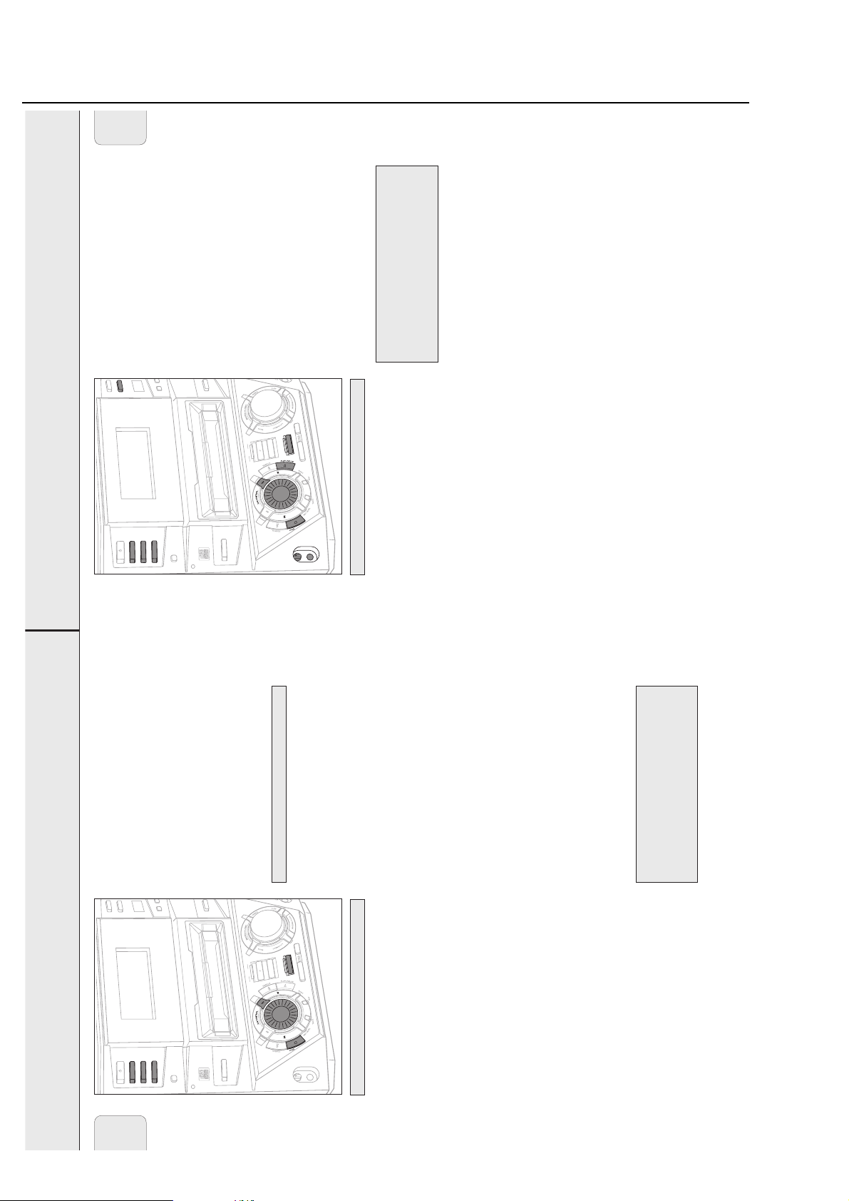
INTERNAL RECORDING
19
yCD Mix Mic is displayed.
wish to mix the microphone.
4 Press CD 1, CD 2 or CD 3 to select the disc with which you
5 Press REC TYPE on the unit to enter the recording menu.
6 Rotate í JOG CONTROL ë to select the manual recording
G
R
O
L
O
A
S
N
A
/
L
A
T
I
G
I
D
AUX
CLOCK/TI
N
E
S
R
i
CD TEXT
R
E
N
U
T
1
CD
CD 3
STANDBY
ON
CD 2
yWait and Record? are displayed.
mode for the microphone:
7 Press YES to confirm.
E
S
O
L
C
/
N
E
P
O
M
E
T
S
Y
S
I
F
I
H
I
N
I
M
E
L
B
A
D
R
O
C
E
R
D
C
R8
FW-
R
E
G
D
IN
R
IT
O
D
C
E
E
T
X
R
E
T
-
D
D
C
C
Y
ISPLA
D
CDR
playing time of the track are displayed.
yThe disc tray number, the current track number and
8 Press YES to start recording.
9 Rotate í JOG CONTROL ë to select the desired track.
D
C
E
L
I
D
P
C
M
D
O
R
C
O
D
C
C
E
R
ALC
– play a recorded CDRW on a CDRW compatible CD player
yThe selected source is mixed with the microphone.
10 Press É PLAY/PAUSE to start playback.
E
S
A
R
E
E
P
Y
T
C
E
R
E
Z
I
L
A
N
I
F
IT
D
E
L
E
C
I
V
E
M
L
recording” in chapter “External recording”.
11 Press Ç STOP to stop recording.
• To perform microphone recording only, see “Manual
C
I
M
Manual recording
– play a recorded CDR on a standard CD player or
DO NOT FORGET TO FINALIZE!
Finalizing a CDR(W) disc is a simple procedure, necessary to:
dust particles.
Manual recording from the FM tuner
1 Make sure the CDR(W) is absolutely free of scratches and
2 Press TUNER repeatedly to select the FM tuner. Then select
and CD recorder.
manual recording starts and the actual recording time
the desired radio station (see “Tuning to radio stations”).
3 Press REC TYPE on the unit to enter the recording menu.
yWait and Record? are displayed.
4 Press YES to confirm.
yFM Tuner? is displayed.
remaining starts to count down.
yThe arrow lights, RECORDING IN PROGRESS is shown,
5 Press YES to start recording.
6 Press Ç STOP to stop recording.
dust particles.
feedback (e.g. a loud howling sound) before you connect
Manual microphone recording
1 Make sure the CDR(W) is absolutely free of scratches and
the microphone.
2 Set MIC LEVEL to the minimum level to prevent acoustic
3 Connect a microphone to MIC.
starts blinking. The remaining recording time of the
CDR(W), the total recording time of the CDR(W) and
either Record CD1 (or 2, 3)?, Record Prog? or
Record A-B? is displayed.
yBoth decks will be selected in the display, the arrow
5 Press YES to confirm your selection.
G
R
O
L
O
A
S
N
A
/
L
A
T
I
G
I
D
AUX
CLOCK/TI
N
E
S
R
i
CD TEXT
R
E
N
U
T
M
E
T
S
Y
S
I
F
I
H
I
N
I
M
E
L
B
A
D
R
O
1
CD
CD 3
STANDBY
ON
CD 2
INTERNAL RECORDING
English
will be shown.
ALC
will also become active and
Note: When the CDR(W) already contains a recording,
C
E
R
D
C
R8
FW-
DISPLAY
speed recording starts and the actual recording time
remaining starts to count down.
yThe arrow lights, RECORDING IN PROGRESS is shown, high
6 Press YES to start high speed recording.
E
S
O
L
C
/
N
E
P
O
R
E
G
D
IN
R
IT
O
D
C
E
E
T
X
R
E
T
-
D
D
C
C
CDR
Normal recording and listening
• To stop recording, press Ç STOP on the unit.
Normal recording and listening of an entire disc, a
E
S
A
R
E
E
P
Y
T
D
C
C
E
E
R
L
I
D
P
C
E
M
D
R
O
C
E
R
Z
I
O
L
C
D
A
C
N
I
F
L
E
C
I
V
E
M
L
track, a program or a track edit
1 Make sure the CDR(W) is absolutely free of scratches and
IT
D
E
C
I
M
normal recording
normal recording
following normal record options:
dust particles.
If CD changer is selected:
2 Follow steps 2 and 3 of “High speed recording”.
3 Rotate í JOG CONTROL ë to select one of the
High speed recording
High speed recording of an entire disc, a track, a
program or a track edit
1 Make sure the CDR(W) is absolutely free of scratches and
• Press YES to confirm.
yCD Listen?: for listening to the entire disc during
yTrackListen?: for listening to the track during
dust particles.
which you wish to record.
2 Press either CD 1, CD 2 or CD 3 to select the disc from
track.
yRec Tr and the track number is displayed.
• Continue with step 6 of “High speed recording”.
• Rotate í JOG CONTROL ë to select the desired
3 Press REC TYPE on the unit to enter into the recording menu.
4 Rotate í JOG CONTROL ë to select one of the
normal recording
If CD changer program mode is available:
yProg Listen?: for listening to the program during
• Continue with step 5.
If a disc from the CD changer is selected:
yCD Fast?: for high speed recording of an entire disc
following high speed recording modes:
normal recording
If CD changer track edit mode is available:
yA-B Listen?: for listening to the A–B track during
4 Follow steps 5 and 6 of “High speed recording”.
• To stop recording, press Ç STOP on the unit.
yRec Tr and the track number is displayed.
• Continue with step 6.
• Press YES to confirm.
• Rotate í JOG CONTROL ë to select the track.
yTrack Fast?: for high speed recording of a track
disc or of the program
If CD changer program mode is available:
yProg Fast?: for high speed recording of the selected
and CD recorder.
– play a recorded CDRW on a CDRW compatible CD player
– play a recorded CDR on a standard CD player or
DO NOT FORGET TO FINALIZE!
Finalizing a CDR(W) disc is a simple procedure, necessary to:
If CD changer track edit mode is available:
yA-B Fast?: for high speed recording of the A–B track
18

2-11
Brief Operating Instructions
EXTERNAL RECORDING
21
Manual recording from an external source
1 Make sure the CDR(W) is absolutely free of scratches and
dust particles.
2 Repeatedly press DIGITAL / ANALOG AUX to select the
input for the external source from which you want to record.
yAUX Digital is displayed if the digital input is
selected.
yAUX Analog is displayed if the analog input is selected.
3 Press REC TYPE on the unit to enter the recording menu.
4 Rotate í JOG CONTROL ë to select the type of recording.
yAUX Manual?: for manual start of recording
5 Press YES to confirm your selection.
yWait is displayed.
yRecord?, AUX and the remaining recording time of
the CDR(W) are displayed.
6 Start playback on the external source in order to set the
optimal recording level on the CD recorder (see
“REC LEVEL key”).
7 Stop playback on the external source.
8 Go to the beginning of the desired track.
9 Press YES on the unit and simultaneously start playback on
the external source.
yThe CD recorder starts to record and RECORDING IN
PROGRESS
is shown. The remaining recording time of the
CDR(W) is displayed.
Note: If
Check Input
is flashing, check the digital
connection.
10 Press Ç STOP on the unit to stop recording.
yUpdate is displayed and RECORDING IN PROGRESS goes off.
Manual microphone recording
1 Make sure the CDR(W) is absolutely free of scratches and
dust particles.
2 Set MIC LEVEL to the minimum level to prevent acoustic
feedback (e.g. a loud howling sound) before you connect
the microphone.
3 Connect a microphone to MIC.
4 Repeatedly press DIGITAL / ANALOG AUX to select the
input for the external source with which you wish to mix
the microphone.
yAUX Digital is displayed if the digital input is
selected.
yAUX Analog is displayed if the analog input is selected.
5 Press REC TYPE on the unit to enter the recording menu.
6 Rotate í JOG CONTROL ë to select the type of recording:
yAUX Mix Mic: the microphone is mixed with the
external source.
yMic Only: only the microphone is recorded.
7 Press YES to confirm your selection.
yWait is displayed.
yRecord?, AUX and the remaining recording time of
the CDR(W) are displayed.
8 Set the optimal recording level on the CD recorder (see
“REC LEVEL key”).
• In addition, you can also set the optimal recording level
of the microphone by turning MIC LEVEL.
9
If
AUX Mix Mic
is selected:
Press YES on the unit and simultaneously start playback on
the external source.
yThe CD recorder starts to record and RECORDING IN
PROGRESS
is shown. The remaining recording time of the
CDR(W) is displayed.
If
Mic Only
is selected:
Press YES on the unit to start recording.
yThe CD recorder starts to record and RECORDING IN
PROGRESS
is shown. The remaining recording time of the
CDR(W) is displayed.
10 Press Ç STOP on the unit to stop recording.
yUpdate is displayed and RECORDING IN PROGRESS goes off.
DO NOT FORGET TO FINALIZE!
Finalizing a CDR(W) disc is a simple procedure, necessary to:
– play a recorded CDR on a standard CD player or
– play a recorded CDRW on a CDRW compatible CD player
and CD recorder.
Manual recording
English
EXTERNAL RECORDING
or after 2.7 seconds of silence in analog recordings.
RECORDING IN PROGRESS is shown. The remaining
yThe CD recorder starts to record simultaneously and
6 Start playback on the selected source.
G
O
L
A
N
A
/
L
A
T
I
G
I
D
R
E
N
AUX
U
T
STANDBY
ON
English
track, recording starts at the beginning of the next track
recording time on the CDR(W) is displayed.
R
O
S
N
E
S
R
i
1
CD
CD 2
If a digital source is selected:
After the recording process, the CD recorder stops
Note: If you start playback on the selected source within a
ER
TIM
/
CLOCK
CD TEXT
M
E
T
S
Y
S
I
F
I
H
I
N
I
M
E
L
B
A
D
R
O
C
E
R
D
C
R8
FW-
CD 3
Y
ISPLA
D
automatically.
7
E
S
O
L
C
/
N
E
P
O
R
E
G
D
IN
R
IT
O
D
C
E
E
T
X
R
E
T
-
D
D
C
C
CDR
after 20 seconds of silence.
At the end of the recording process, the CD recorder stops
after a silence of 20 seconds on the source material.
If an analog source is selected:
Note: Recordings from DAT or DCC will automatically stop
D
C
E
L
I
D
P
C
M
D
O
R
C
O
D
C
C
E
R
yRECORDING IN PROGRESS goes off.
• To stop recording manually, press Ç STOP on the unit.
E
S
A
R
E
E
P
Y
T
C
E
R
E
Z
I
L
A
N
I
F
IT
D
E
– play a recorded CDR on a standard CD player or
DO NOT FORGET TO FINALIZE!
Finalizing a CDR(W) disc is a simple procedure, necessary to:
L
C
E
C
I
I
V
M
E
M
L
Analog or digital recording?
When making recordings from an external source, we
and CD recorder.
– play a recorded CDRW on a CDRW compatible CD player
recommend to do analog recording only if digital recording is
not possible. Digital recording will usually result in better
sound quality.
selected.
yAUX Digital is displayed if the digital input is
Recording with automatic start
dust particles.
Recording of an entire disc or a track with automatic
start
1 Make sure the CDR(W) is absolutely free of scratches and
yAUX Analog is displayed if the analog input is selected.
input for the external source from which you want to record.
2 Repeatedly press DIGITAL / ANALOG AUX to select the
3 Press REC TYPE on the unit to enter the recording menu.
entire disc
a track
yAUX CD?: for recording with synchronized start of an
yAUX Track?: for recording with synchronized start of
4 Rotate í JOG CONTROL ë to select either:
time of the CDR(W) are displayed.
yStart Source, AUX and the remaining recording
5 Press YES to confirm your selection.
20

2-12
Brief Operating Instructions
English
(UN)FINALIZING, ERASING
tracks to be erased are displayed. All track numbers will
blink in the music calendar.
starts to count down. The track number of the actual
yErase?, the total playing time and the total number of
5 Press YES to confirm your selection.
erased track will go off in the music calendar.
yErase is displayed and the operation time remaining
6 Press YES to start erasing.
the CD recorder tray.
Erasing one or more tracks
1 Insert the CDRW from which you want to erase tracks in
yErase and the track number (e.g. 10+)? are displayed.
2 Press CDR to select the CD recorder.
you wish to erase.
3 Press ERASE to enter the erasing menu.
4 Rotate í JOG CONTROL ë to select the track number(s)
• To select more tracks to be erased, repeat step 4.
tracks 5 and 3!
can also erase tracks 5, 4 and 3, but you cannot erase
recorded on it. Now, you can erase tracks 5 and 4. You
recorded track. Example: The CDRW has 5 tracks
must be selected in sequence, starting from the last
Note: When erasing more tracks, the tracks to be erased
music calendar. The remaining track numbers light up.
yAll track numbers selected for erasing will blink in the
5 Press YES to confirm your selection.
starts to count down. The track number of the currently
yErase? is displayed.
erased track will go off in the music calendar.
yErase is displayed and the operation time remaining
6 Press YES to start erasing.
23
CDRW
changes to
CD
available, this text will be transferred to the
on the display.
– When unfinalizing a CDRW with CD text on it
– After unfinalizing of the CDRW,
Unfinalizing CDRW discs
If you want to record (or erase) on (from) a finalized CDRW,
you have to unfinalize it first.
Notes: – Unfinalizing will take approximately 2 minutes.
E
S
A
R
E
E
P
Y
T
D
C
C
E
E
R
IL
D
P
C
D
R
O
D
C
C
E
R
E
M
IZ
O
L
C
A
IN
F
”)
Erasing from the memory
“
have to erase text (see
CD recorder memory. In case the memory is full, you
memory space.
or to finalize another disc first in order to obtain
tray.
1 Insert the CDRW you want to unfinalize in the CD recorder
yUnfinalize? is displayed.
2 Press CDR to select the CD recorder.
3 Press FINALIZE on the unit.
D
C
E
IL
D
P
C
M
D
O
R
C
O
D
C
C
E
R
starts to count down.
yUnfinal is displayed and the operation time remaining
4 Press YES to start unfinalizing.
Erasing from a CDRW disc
changes to
CDR(W)
E
S
A
R
E
E
P
Y
T
C
E
R
E
IZ
L
A
IN
F
EDIT
It is possible to erase one or more tracks (starting from the
end of the last track) or the entire CDRW.
Erasing an entire CDRW
1 Insert the CDRW you want to erase in the CD recorder tray.
2 Press CDR to select the CD recorder.
yErase Disc?: for erasing the entire disc
3 Press ERASE to enter the erasing menu.
4 Rotate í JOG CONTROL ë to select:
EDIT
increments are now automatically detected from digital
source material. In analog source material, a silence of
yAuto Tr ON is displayed and the function is on. Track
as often as necessary TRACK INCR. on the remote control
Automatic track increment
EXTERNAL RECORDING (UN)FINALIZING, ERASING
In recording mode, tracks will be incremented automatically so
that the track numbers are in the same position as the original.
during stop when CDR is selected.
• To switch the automatic track increment function on, press
English
on the display.
CD
can be executed.
– After finalization of the CDR(W),
and CD recorder,
– play a recorded CDR on a standard CD player,
– play a recorded CDRW on a CDRW compatible CD player
– avoid further unwanted recordings on a disc, or
Finalizing CDR(W) discs
Finalizing a CDR(W) disc is a simple procedure, necessary to:
2.7 seconds or more is detected as a track increment.
as often as necessary TRACK INCR. on the remote control
during stop when CDR is selected.
• To switch the automatic track increment function off, press
– avoid erasure of tracks on a CDRW.
Track numbers can now be incremented manually by
pressing TRACK INCR. on the remote control during
recording. The minimum track length is 4 seconds.
yAuto Tr OFF is displayed and the function is off.
– During finalization no other operating commands
Notes: – Finalizing will take about 2–4 minutes.
standard. DAT, DVD and DCC do not deliver this
according to the IEC 958 (consumer part) audio
consumer sources with a digital output signal
– The automatic track increment only works with
Notes: – Track numbers cannot be changed after recording.
and the actual finalizing time left will start to count down.
yAuto Final? is displayed.
yFINALIZE is shown. The finalization will start after recording
2 Press YES to confirm.
Auto finalizing
When using either CD™CD or COMPILE CD, your recordings
will be finalized automatically (see “High speed recording and
automatic finalizing”).
Manual finalizing when recording is in progress
1 Press FINALIZE on the unit during recording.
Manual finalizing when recording is stopped
signal.
1 Insert the CDR(W) you want to finalize in the CD recorder tray.
2 Press CDR to select the CD recorder.
finalizing time left starts to count down.
yFinalize? is displayed.
yFINALIZE is shown, Final is displayed and the actual
4 Press YES to start finalizing.
3 Press FINALIZE on the unit.
22

2-13
Brief Operating Instructions
PE
FEATURES
25
Erasing text
1 Press EDIT TEXT to enter the text edit menu.
yCD TEXT EDIT is blinking, Text Edit is displayed.
2 Rotate í JOG CONTROL ë to select the text erase menu.
yText Erase is displayed.
3 Press YES to confirm.
4 Rotate í JOG CONTROL ë to select one of the following:
yAll Text: All text of the selected disc is chosen to
be erased in one step.
yAlbum Artist: CD artist’s name is chosen to be
erased.
yAlbum Title: CD title is chosen to be erased.
yArtist Tr 1 or (2, 3,…): artist’s name of track 1 or
(2, 3,…) is chosen to be erased.
yTitle Tr 1 or (2, 3,…): title of track 1 or (2, 3,…)
is chosen to be erased.
5 Press YES to confirm your selection.
yErase? or Erase All? is displayed.
6 Press YES to start erasing.
yUpdate is displayed and the chosen text is erased.
Erasing from the memory
When the text memory of your CD recorder is full, the messages
Memory Full and Finalize Disc will be displayed. If
you still want to add a new disc to the text memory, you either
have to erase another disc from the memory or you have to
finalize another disc.
1 Press EDIT TEXT to enter the text edit menu.
yCD TEXT EDIT is blinking, Text Edit is displayed.
2 Rotate í JOG CONTROL ë to select the memory view
menu.
yText Memory is displayed.
3 Press YES to confirm.
4 Rotate í JOG CONTROL ë to select the disc you wish to
erase from the text memory.
5 Press YES to confirm.
yErase Memory is displayed.
6 Press YES to confirm the text erasure of that particular disc.
Note: If there are no discs stored in the text memory,
Memory Empty
will be displayed.
You can create a “track” by marking a passage of music within
one track on the current disc. This new “track” can be used for
recording or playing. The minimum track length is 4 seconds.
1 Press EDIT TRACK on the unit.
yEDIT TRACK starts blinking, Track and the current track
number ? are displayed. The current track number also
blinks in the music calendar.
2 Rotate í JOG CONTROL ë until the desired track
number is displayed.
3 Press YES to confirm the selected track.
yThe marker position A and the track time will be
displayed. The first 4 seconds of the track will be played
continuously.
4 Press É PLAY/PAUSE on the unit to play to the desired
start position of your new “track” (The initial position of
marker A is always the start of the chosen track).
• To fast forward to the desired start position, press
à SEARCH or á SEARCH on the unit.
• To fine tune the position, first press É PLAY/PAUSE on the
unit, then rotate í JOG CONTROL ë.
5 Press YES to confirm the position of marker A.
yThe marker position B and the new “track” time will be
displayed. The first 4 seconds before marker position B
until marker position B will be played continuously.
6 Press É PLAY/PAUSE on the unit to play to the stop position
of your new “track” (the initial position of marker B is always
the position of marker A plus 4 seconds).
7 Press YES to confirm the marked passage.
yEDIT TRACK is shown, A-B and the track edit time are
displayed.
Note: If you open the CD changer tray, the edit is deleted.
Clearing the track edit
1 Press NO during stop.
yClear A-B? is displayed.
2 Press YES to clear the markers.
yThe markers A-B are cleared.
Track editing (on CD changer only)
English
Storing text during recording
You can store and edit text even while recording a single
track or single CD, or when recording from an external source
or tuner. Editing text during finalizing is not possible. Make
sure, when using high speed recording and automatic
finalizing, to enter the text before finalizing starts, otherwise
automatic finalizing will be cancelled.
D
C
E
REC TY
IL
D
P
C
D
C
RECORD
E
M
IZ
O
L
C
A
IN
F
L
E
IC
V
E
M
L
FEATURES
CDText
is displayed and your text is saved for later
Saved
editing.
is analog recorded. Editing is stopped,
• Follow steps 3–10 of “Storing text during stop mode”.
Note: Editing text is not possible when a copy protected track
IT
D
E
IC
M
Auto copied text
When an artist’s name has been stored for a track, it will be
EDIT TEXT (on CD recorder only)
Storing text during stop mode
After you have recorded your CDR(W) you can enter text, e.g.
EDIT TEXT to confirm the copied text,
or
copied automatically into the next track.
• Press either:
names to discs and tracks. The text will be displayed during
playback. You can enter up to 60 characters per text field.
Only use an unfinalized CDR or CDRW (finalized CDRW must
be unfinalized first).
1 If necessary, press Ç STOP on the unit (Ç on the remote
NO to delete the copied text and enter new text.
control) to stop playback.
yThe position starts blinking.
control) to move to the position where the space is to be
inserted.
Inserting a space
1 Press à SEARCH or á SEARCH (à or á on the remote
2 Press CDR to select the CD recorder.
2 Press YES to confirm the position of the insert character.
yCD TEXT EDIT is blinking, Text Edit is displayed.
4 Press YES to confirm.
3 Press EDIT TEXT on the unit to enter the text edit menu.
control) to move to the character’s position to be deleted or
yA space will be inserted, text will move to the right.
Deleting and substituting a character
1 Press à SEARCH or á SEARCH (à or á on the remote
track 1 or (2, 3,…).
yAlbum Artist: for editing the CD artist.
yAlbum Title: for editing the CD title.
yArtist Tr 1 or (2, 3,…): for editing the artist of
5 Rotate í JOG CONTROL ë to select either:
substituted.
yThe character starts blinking.
position to the left.
If you want to delete the character:
Press NO.
yThe character is deleted and the text is shifted one
2
If you want to substitute the character:
or (2, 3,…).
yTitle Tr 1 or (2, 3,…): for editing the title of track 1
the remote control) to select a character.
6 Press YES to confirm the selection.
7 Rotate í JOG CONTROL ë (press the alphabet keys on
8 Press YES to confirm the selection.
Rotate í JOG CONTROL ë (press the alphabet keys on
yThe cursor moves to the next character space.
á SEARCH (à or á on the remote control).
the remote control) to select a new character.
Press YES to confirm the selection.
• To change another character, press à SEARCH or
selected and to exit to the last position in the text editing
menu.
9 Repeat steps 7 and 8 for adding further characters.
yUpdate is displayed.
10 Press EDIT TEXT to save the characters that have been
24
English
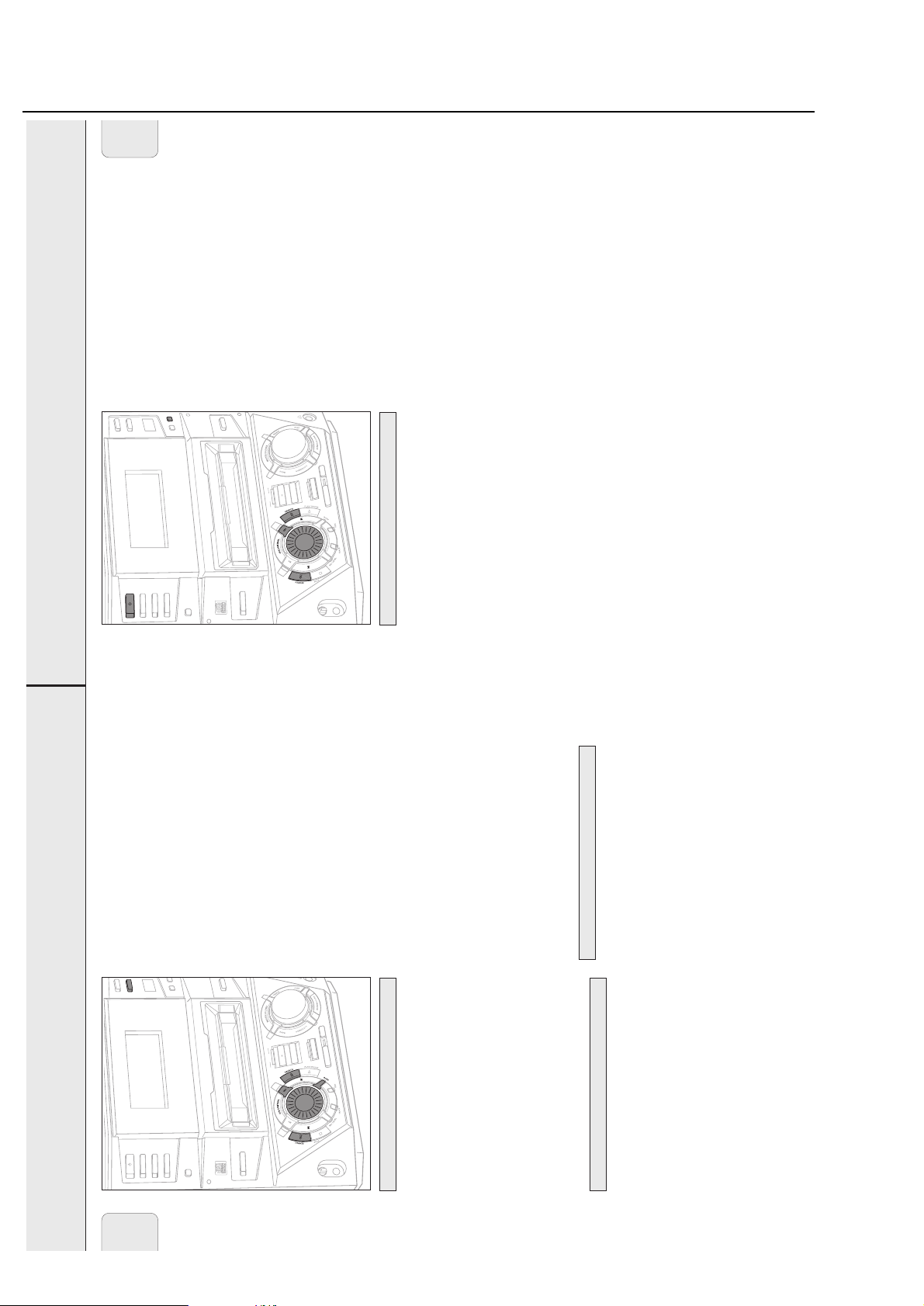
2-14
Brief Operating Instructions
M
English
CLOCK/TIMER
TIMER
G
O
L
A
N
A
/
L
A
T
I
G
I
D
/
R
O
S
CLOCK
N
E
S
R
i
CD TEXT
R
E
N
AUX
U
T
E
S
O
L
C
/
N
E
P
O
M
E
T
S
Y
S
I
F
I
H
I
N
I
M
E
L
B
A
D
R
O
C
E
R
D
C
R8
FW-
R
E
G
D
IN
R
IT
O
D
C
E
E
T
X
R
E
T
-
D
D
C
C
27
E
S
A
R
E
E
P
Y
T
D
C
C
E
E
R
L
I
D
P
C
E
M
D
R
O
C
E
R
Z
I
O
L
C
D
A
C
N
I
F
IT
D
E
1
CD
CD 3
STANDBY
ON
CD 2
DISPLAY
CDR
L
C
E
C
I
I
V
M
E
M
L
switch the unit to standby.
Clock setting
Manual clock setting
1 Press y STANDBY ON as often as necessary on the unit to
2 Press CLOCK/TIMER on the unit.
3 Rotate í JOG CONTROL ë to select the clock.
yClock is displayed and X starts blinking.
yThe day of the week digit blinks.
4 Press YES to confirm the selection.
5 Rotate í JOG CONTROL ë to set the day.
day of the week to hour.
6 Use à SEARCH or á SEARCH on the unit to move from
7 Rotate í JOG CONTROL ë to set the hour.
8 Repeat steps 6 and 7 to set the minutes.
9 Press YES to confirm the settings.
PROG goes off, the preset number,
the waveband and the frequency of the last preset station
are displayed briefly.
stored automatically.
preset number in the music calendar start blinking.
yAutoprogram is displayed, PROG and the current
yAll available radio stations for the selected waveband are
more than 2 seconds.
2 Keep PROG (PROGRAM on the remote control) pressed for
G
R
O
L
O
A
S
N
A
/
L
A
T
I
G
I
D
CLOCK/TI
N
E
S
R
i
CD TEXT
R
E
N
AUX
U
T
M
E
T
S
Y
1–2. Make sure to select the next available preset number
first before proceeding, otherwise already programmed
radio stations may be erased.
• To store radio stations for another waveband, repeat steps
E
S
O
L
C
/
N
E
P
O
S
I
F
I
H
I
N
I
M
E
L
B
A
D
R
O
C
E
R
D
C
R8
FW-
R
E
G
D
IN
R
IT
O
D
C
E
E
T
X
R
E
T
-
D
D
C
C
first, followed by the weak stations.
on the remote control).
• To exit the automatic programming, press PROG (PROGRAM
Note: Strong stations will always automatically be programmed
Manual programming
1 Follow steps 1 and 2 of “Tuning to radio stations”.
E
S
A
R
E
E
P
Y
T
D
C
C
E
E
R
L
I
D
P
C
E
M
D
R
O
C
E
R
Z
I
O
L
C
D
A
C
N
I
F
IT
D
E
calendar start flashing.
yPROG and the current preset number in the music
less than 2 seconds.
2 Keep PROG (PROGRAM on the remote control) pressed for
control) to tune to the desired radio station.
3 Press à SEARCH or á SEARCH (à or á on the remote
rotate í JOG CONTROL ë (pressí or ë on the
• To allocate the radio station to another preset number,
the frequency of the preset station are displayed.
yPROG goes off, the preset number, the waveband and
remote control).
4 Press YES to confirm the setting.
the remote control).
Tuning to preset stations
• To exit manual programming, press PROG (PROGRAM on
until the preset number of the desired station is displayed.
• Use í JOG CONTROL ë (í or ë on the remote control)
TUNER
STANDBY
ON
English
1
CD
CD 3
CD 2
DISPLAY
CDR
L
C
E
C
I
I
V
M
E
M
L
yTuner is scrolled.
Tuning to radio stations
yThe selected waveband is displayed.
2 Press TUNER again to select the desired waveband.
1 Press TUNER to select the tuner.
The radio tunes to a station with sufficient signal strength.
control) pressed for more than a half second.
yThe selected waveband and Searching are displayed.
3 Keep à SEARCH or á SEARCH (à or á on the remote
á SEARCH (à or á on the remote control) as often as
necessary for optimum reception.
4 Repeat searching until you find the desired station.
• To tune to a weak station, briefly press à SEARCH or
Storing radio stations
It is possible to store up to 40 radio stations. Stations can be
selected and programmed automatically or you can do that
yourself. Programming will overwrite your former presets
starting from the last active preset station. After programming
the last stored preset station will be tuned.
Automatic programming
If no preset is tuned, automatic programming starts at preset
number one.
1 Follow steps 1 and 2 of “Tuning to radio stations”.
26
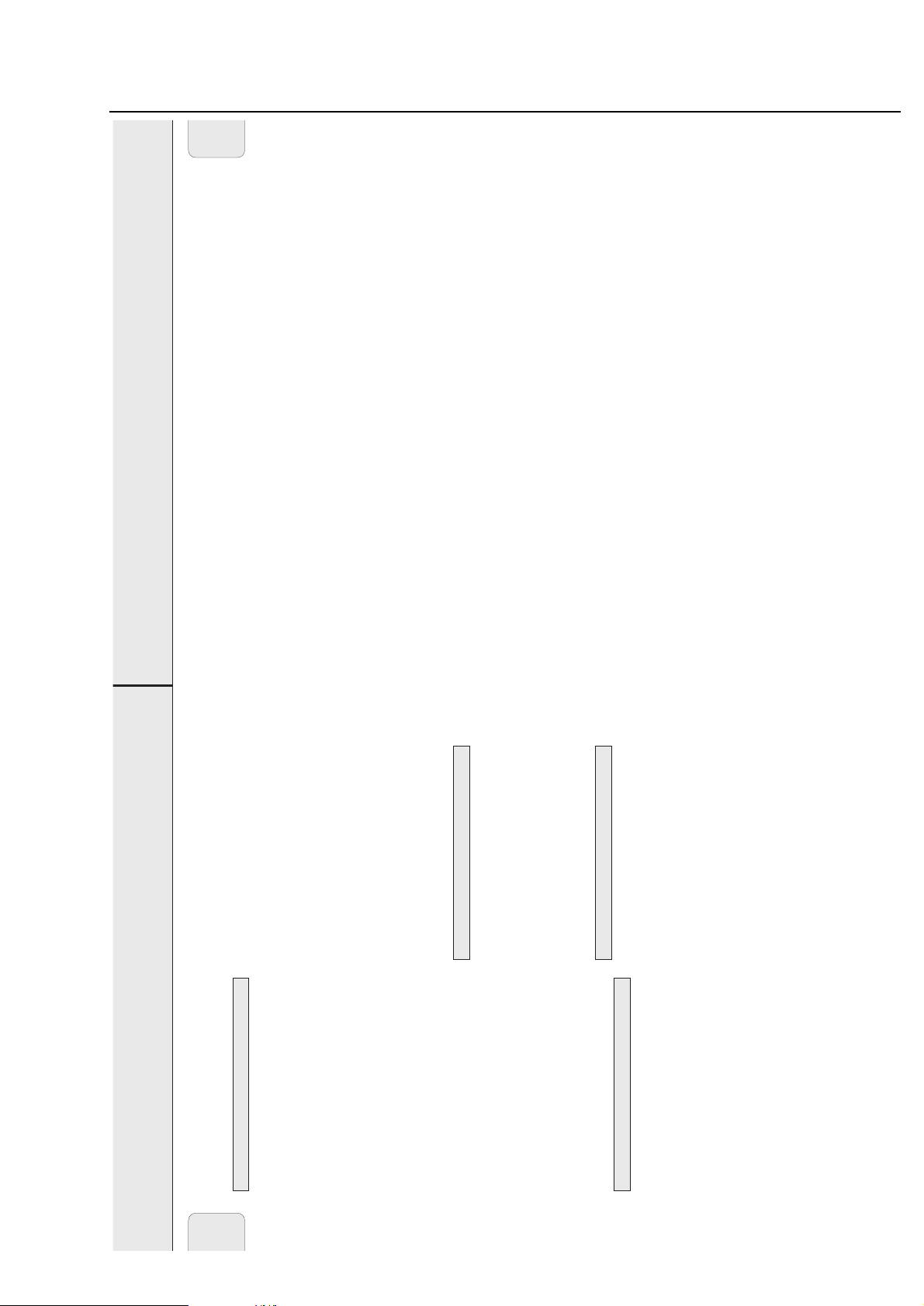
2-15
Brief Operating Instructions
TECHNICAL DATA
29
Subject to modification without notice.
General
AC Power ..............................................................120 V / 60 Hz
Power consumption
Active.........................................................................148 W
Standby.....................................................................< 30 W
Economy power save mode .......................................< 2 W
Dimensions, w × h × d ...........................10.4 × 12.2 × 15.6 in.
Weight (without speakers) ................................................11 kg
Amplifier
Output power................2 × 100 W FTC, 6 Ω, 1 kHz, THD 10%
Frequency response ................60–12,500 Hz FTC, +0.5/-1.5 dB
S/N ratio..............................................................≥ 80 dBA (IEC)
Input sensitivity
AUX IN L/R...............................................................800 mV
MIC...............................................................................1 mV
DIGITAL IN..............................500 mV
pp
(75 Ω)/12–56 kHz
Output
Impedance speakers...................................................≥ 6 Ω
Impedance headphones..................................32 Ω–600 Ω
LINE OUT L/R ...........................................................500 mV
DIGITAL OUT..............................500 mV
pp
(75 Ω)/44.1 kHz
SUBWOOFER OUT...........................................................1 V
CD changer
Number of programmable tracks............................................40
Frequency range ...................................................20–20,000 Hz
S/N ratio......................................................................≥ 92 dBA
Cross talk ..........................................................≤-65 dB (1 kHz)
Total harmonic distortion..................................≤-94 dB (1 kHz)
CD recorder
Number of programmable tracks............................................99
CD playback
Frequency range.............................................20–20,000 Hz
S/N ratio playback ................................................≥92 dBA
Cross talk....................................................≤ -65 dB (1 kHz)
Total harmonic distortion...........................≤ -84 dB (1 kHz)
Analog recording, digital playback
Frequency range.............................................20–20,000 Hz
S/N ratio playback ................................................≥86 dBA
Cross talk....................................................≤ -65 dB (1 kHz)
Total harmonic distortion...........................≤ -81 dB (1 kHz)
Laser (CD recorder)
Type..............................................Semiconductor laser GaAIAs
Wave length...........................................775–795 nm (at 25° C)
Output power............................2.5 mW (Read), 35 mW (Write)
Beam divergence........................................................60 degree
Tuner
Wave range
FM..............................................................87.5–108.0 MHz
AM................................................................530–1,700 kHz
Speakers
System............................................................3 way bass reflex
Impedance............................................................................6 Ω
Woofer ...........................................................................1 ×6.5"
Tweeter ...........................................1 ×2.5", Ferro fluid cooled
Tweeter ..........................................................1 × 1", Polydome
Dimensions, h × w × d .............................12.2 × 9.4 × 12.7 in.
Weight .....................................................................4.6 kg/each
English
displayed when the alarm and record timer are on.
when the alarm and record timer are off.
the record timer is on.
hour to minutes of start of recording.
recording.
5 Use à SEARCH or á SEARCH on the unit to move from
6 Rotate í JOG CONTROL ë to set the minutes of start of
CLOCK/TIMER
You can select different timer functions which will be activated
Alarm timer
at a chosen time. Make sure the clock is set before using one
of these features.
á SEARCH to move on to hour and minutes of end of
recording and to the day of the week. After each move,
always rotate í JOG CONTROL ë to do the settings.
7 Continue this procedure by using à SEARCH or
Alarm timer setting
The unit can be used as an alarm clock, whereby the tuner,
CD recorder or CD changer starts playback automatically at a
preset time.
want to record.
8 Press YES to confirm the settings.
1 Press y STANDBY ON as often as necessary on the unit to
If you have chosen the tuner as source:
9 Rotate í JOG CONTROL ë to select from which you
switch the unit to standby.
2 Press CLOCK/TIMER on the unit.
Rotate í JOG CONTROL ë again to select a preset radio
station and confirm this selected station by pressing YES.
10 Press YES on the unit to confirm the source selection.
yAlarm is displayed, ALARM is blinking.
yThe hour digit is blinking.
4 Press YES to confirm the selection.
3 Rotate í JOG CONTROL ë to select the alarm timer.
Switching the alarm and record timer on/off
• To stop the recording press Ç STOP on the unit.
5 Rotate í JOG CONTROL ë to set the hour.
6 Use à SEARCH or á SEARCH on the unit to move from
alarm timer is on.
switch the alarm and/or record timer on or off:
y ALARM is shown and Alarm ON is displayed when the
y REC is shown and REC Timer ON is displayed when
• Press TIMER ON/OFF on the remote control repeatedly to
hour to minutes.
7 Rotate í JOG CONTROL ë to set the minutes.
8 Press YES to confirm the time settings.
y ALARM and REC are shown, REC+Alarm ON is
y ALARM and REC go off, REC+AlarmOFF is displayed
Sleep timer
You can set a certain period of time before the unit switches off.
to be woken up with.
9 Rotate í JOG CONTROL ë to select the source you want
10 Press YES on the unit to confirm the source selection.
• To stop the alarm, press y STANDBY ON on the unit.
Record timer
min,15 min is displayed or, Sleep OFF is displayed.
time is displayed.
ySLEEP is shown and Sleep 60 min, 45 min, 30
1 Press SLEEP on the remote control until the desired sleeper
Record timer setting
The unit can do recordings automatically from an external
source or from a preset radio station at a preset time.
1 Follow steps 1 and 2 of “Alarm timer setting”.
standby.
control until Sleep OFF is displayed.
yAfter the chosen time has elapsed, the unit switches to
SLEEP again.
2 As soon as the desired time is displayed, do not press
2 Rotate í JOG CONTROL ë to select the record timer.
• To deactivate the sleep timer, press SLEEP on the remote
yRec Timer is displayed, REC is shown and X starts
blinking.
recording.
yThe hour digit for the start of recording blinks.
3 Press YES on the unit to confirm the selection.
4 Rotate í JOG CONTROL ë to set the hour of start of
28
English

2-16
Brief Operating Instructions
TROUBLESHOOTING
30
English
PROBLEM POSSIBLE CAUSE SOLUTION
No sound, Volume is not correctly adjusted. Adjust the volume.
no power
Headphones are connected. Disconnect headphones.
Speakers are wrongly or not connected. Make sure speakers are properly connected.
Power cable is not securely connected. Connect power cable properly.
No reaction to Electrostatic discharge Disconnect the unit from power supply, then
controls reconnect after a few seconds.
Poor radio reception Weak radio signal Direct the antenna for optimum reception.
Antenna is positioned near a radiation source Change the position of the interfering unit or
such as a TV, VCR, computer, etc. try to switch it off.
Poor bass sound Speakers are not in phase. Connect the colored (or marked) wires to the
colored terminals and the black (or unmarked)
wires to the black terminals.
Bad sound Badly matched setting for the given type of Correct the sound settings on the unit.
music or sound.
Remote control does not Batteries are inserted incorrectly. Insert batteries correctly.
function properly
Batteries are flat. Insert new batteries.
Distance to the unit is too large. Reduce distance.
Insert Disc indication The CD(RW) is scratched badly or dirty. Replace or clean the disc.
No CD(RW) inserted or inserted upside down. Insert a CD(RW), with label facing upwards.
The laser lens is steamed up. Wait until the lens has cleared.
Wrong Disc indication, No digital audio disc is inserted. Insert a digital audio disc marked with “Digital
Use Audio CD indication Audio” and the special logo.
Disc Recover indication Power loss Wait a few minutes. The disc is being repaired.
Disc Error indication Disc Recover was not able The disc can still be played, but not recorded
to repair the disc. or finalized further.
Check Input indication Wrong input is chosen. Select the correct input.
No correct digital source is detected after Make sure the connection cable is properly
starting recording. connected.
Does not record CDR(W) is scratched or dirty. Make sure the CDR(W) is absolutely free of
scratches and dust particles.
The inserted disc is not recordable. Insert a digital CDR(W) and make sure it is
unfinalized.
Recording process is interrupted (power Start recording again.
loss, mechanical shock).
Recorded disc does not The inserted CDR(W) is not finalized. Finalize the CDR(W).
play in another standard
The CDRW is inserted in a non-CDRW Insert the CDRW in a CDRW compatible
CD player
compatible CD player. CD player.
WARNING
Under no circumstances should you try to repair the
unit yourself as this will invalidate the guarantee. Do
not open the unit as there is a risk of electric shock.
If a fault occurs, first check the points listed, before taking
the unit for repair.
If you are unable to solve a problem by following these hints,
consult your dealer or service center.
LASER SAFETY
This unit employs a laser. Only a qualified service
person should remove the cover or attempt to service
this device, due to possible eye injury.

3-1
© WARNING
All ICs and many other semiconductors are susceptible to
electrostatic discharges (ESD). Careless handling during
repair can reduce life drastically.
When repairing, make sure that you are connected with the
same potential as the mass of the set via a wristband with
resistance. Keep components and tools at this potential.
f ATTENTION
Tous les IC et beaucoup d´autres semi-conducteurs sont
sensibles aux décharges statiques (ESD). Leur longévite
pourrait être considérablement écourtée par le fait qu´aucune
précaution nést prise à leur manipulation.
Lors de réparations, s´assurer de bien être relié au même
potentiel que la masse de l´appareil et enfileer le bracelet
serti d´une résistance de sécurité.
Veiller à ce que les composants ainsi que les outils que l´on
utilise soient également à ce potentiel.
d WARNUNG
Alle ICs und viele andere Halbleiter sind empfindlich
gegenüber elektrostatischen Entladungen (ESD).
Unsorgfältige Behandlung im Reparaturfall kann die
Lebensdauer drastisch reduzieren.
Sorgen Sie dafür, daß Sie im Reparaturfall über ein Pulsarmband mit Widerstand mit dem Massepotential des
Gerätes verbunden sind.
Halten Sie Bauteile und Hilfsmittel ebenfalls auf diesem
Potential.
ñ WAARSCHUWING
Alle IC´s en vele andere halfgeleiders zijn gevoelig voor
electrostatische ontladingen (ESD).
Onzorgvuldig behandelen tijdens reparatie kan de levensduur
drastisch doen vermindern. Zorg ervoor dat u tijdens reparatie
via een polsband met weerstand verbonden bent met hetzelfde
potentiaal als de massa van het apparaat.
Houd componenten en hulpmiddelen ook op ditzelfde potentiaal.
i AVVERTIMENTO
Tutti IC e parecchi semi-conduttori sono sensibili alle scariche
statiche (ESD).
La loro longevità potrebbe essere fortemente ridatta in caso di
non osservazione della più grande cauzione alla loro
manipolazione. Durante le riparationi occorre quindi essere
collegato allo stesso potenziale che quello della massa
delápparecchio tramite un braccialetto a resistenza.
Assicurarsi che i componenti e anche gli utensili con quali si
lavora siano anche a questo potenziale.
©
Safety regulations require that the set be restored to its
original condition and that parts which are identical with
those specified be used.
Safety components are marked by the symbol
i
Le norme di sicurezza estigono che l´apparecchio venga
rimesso nelle condizioni originali e che siano utilizzati i
pezzi di ricambiago identici a quelli specificati.
Componenty di sicurezza sono marcati con
ñ
Veiligheidsbepalingen vereisen, dat het apparaat in zijn
oorspronkeliijke toestand wordt teruggebracht en dat
onderdelen, identiek aan de gespecificeerde, worden toegepast.
De Veiligheidsonderdelen zijn aangeduid met het symbool
s Varning !
Osynlig laserstrålning när apparaten är öppnad och
spärren är urkopplad. Betrakta ej strålen.
∂ Advarsel !
Usynlig laserstråling ved åbning når sikkerhedsafbrydere
er ude af funktion. Undgå udsaettelse for stråling.
ß Varoitus !
Avatussa laitteessa ja suojalukituksen ohitettaessa olet alttiina
näkymättömälle laserisäteilylle. Älä katso säteeseen !
f
"Pour votre sécurite, ces documents doivent être utilisés par
des spécialistes agréés, seuls habilités à réparer votre
appareil en panne".
ESD
SAFETY
d
Bei jeder Reparatur sind die geltenden Sicherheitsvorschriften zu beachten. Der Originalzustand des Gerätes
darf nicht verändert werden. Für Reparaturen sind Originalersatzteile zu verwenden.
Sicherheitsbauteile sind durch das Symbol markiert.
f
Les normes de sécurité exigent que l`appareil soit remis
à l`état d`origine et que soient utilisées les pièces de
rechange identiques à celles spécifiées.
Les composants de sécurité sont marqués
CLASS 1
LASER PRODUCT
©
DANGER: Invisible laser radiation when open.
©
After servicing and before returning the set to customer
perform a leakage current measurement test from all
exposed metal parts to earth ground, to assure no
shock hazard exists.
The leakage current must not exceed 0.5mA.
AVOID DIRECT EXPOSURE TO BEAM.
©
AVAILABLE ESD PROTECTION EQUIPMENT :
anti-static table mat large 1200x650x1.25mm 4822 466 10953
small 600x650x1.25mm 4822 466 10958
anti-static wristband 4822 395 10223
connection box (3 press stud connections, 1MΩ) 4822 320 11307
extendible cable (2m, 2MΩ, to connect wristband to connection box) 4822 320 11305
connecting cable (3m, 2MΩ, to connect table mat to connection box) 4822 320 11306
earth cable (1MΩ, to connect any product to mat or to connection box) 4822 320 11308
KIT ESD3 (combining all 6 prior products - small table mat) 4822 310 10671
wristband tester 4822 344 13999
Warnings & Safety

TORX T10 screwdriver with shaftlength 150mm ......................................4822 395 50423
TORX screwdriver set SBC 163 ..............................................................4822 295 50145
Audio signal disc SBC 429......................................................................4822 397 30184
Playability test disc SBC444...................................................................4822 397 30245
Test disc 5 (disc without errors) +
Test disc 5A (disc with dropout errors, black spots and fingerprints)
SBC 426/426A ....................................................................4822 397 30096
Burn in test disc (65 min. 1kHz signal at -30dB level without "pause") ...4822 397 30155
3-2
Service Tools
Handling Chip Components

3-33-3
N
Y
ROTARY ENCODER
TEST
JOG CONTROL
turned ccw
?
Display shows
for 2s.
N
Y
JOG CONTROL
turned cw
?
Display shows
for 2s.
JOG LEFT JOG RIGHT
*
To leave Service Testprogram plug mains cord off.
FW-R8 Service Testprogram Main 2000 03 15
Display shows
version number
of the µP - software.
To enter Service
Testprogram hold
STOP & PLAY
buttons
depressed while
plugging mainscord in.
SERVICE TESTPROGRAM
VARIOUS TESTS
stands for Service mode
stands for version number
of the software used in the
front µP.
S-FW-R8-VXX
VXX
S
NTC XX
N
Y
NTC TEST
Display shows
XX = value in °C
Source = AUX
AUX
button
pressed?
STOP
button
pressed?
N
Y
N
Y
QUARTZ TEST
Display shows
2048Hz can be measured
on pin 9 of µP
N
Y
SEARCH 5
button
pressed?
SEARCH 5
button
pressed?
Tact frequency µP
(divided 32kHz)
32K
Display shows
1465Hz can be measured
on pin 9 of µP
STOP
button
pressed?
N
Y
Tact frequency µP
(divided 12MHz)
12M
NEW
N
Y
EEPROM CLEAR
Display shows
for 1 second
Load default data !
PURE
button
pressed?
PASS
N
Y
EEPROM TEST
Display shows
ERR
Display shows
Testpattern is written to
an address
and
read back again
LOUDNESS
button
pressed?
STOP
button
pressed?
Test ok?
N
Y
N
Y

3-4 3-4
*
To leave Service Testprogram plug mains cord off.
Display shows
version number
of the µP - software.
OPEN/CLOSE
button
pressed?
FINALIZE
button
pressed?
N
Y
N
Y
NEXT
6
button
pressed?
N
Y
PREV
5
button
pressed?
N
Y
STOP
button
pressed?
N
Y
CDR MECHANICAL TEST CDR DC-ERASE MODE
FOCUS TEST
Objective moves
continuously up/down.
SLIDE TEST TRAY TEST
Display shows:
BUSY
Display shows:
BUSY
for visual inspection only
OPEN/CLOSE
button
pressed?
N
Y
Slide moves
continuously in/out.
Display shows:
OPENED
(even when tray is blocked)
Tray opens.
Display shows:
CLOSE
(even when tray is blocked)
Tray closes.
Dependent on the
moving direction,
slide moves to inner
or outer end position.
Exit Mech. Testprogram
SERVICE TESTPROGRAM
CDR MODULE
stands for Service mode
stands for version number
of the software used in the
front µP.
To enter Service
Testprogram hold
PLAY & STOP
buttons
depressed while
plugging mainscord in.
FW-R8 Service Testprogram CDR 2000 02 14
CDR
button
pressed?
TEST O.K.?
NN
N
Y
Y
N
Y
Y
Y
Display shows for 2s each:
• Software version of DASP
(flash ROM 7703)
• Software version of
basic engine processor
(flash EPROM 7208)
CDR ELECTRICAL TEST
ERASE
button
pressed?
N
Y
Disc erased?
N
Y
N
Y
Insert CD-DA disc
before starting the test
MODULE
INFORMATION
MAIN BOARD DIAGNOSTIC
CDR - LOADER TEST
DRAM TEST 7702
Display shows:
DTST1
CHECKSUM TEST 7703
Display shows:
DTST2
ERASE TEST 7208
Display shows:
DTST3
ADC/DAC TEST 7406
Display shows:
DTST4
COMMUNICATION TEST
(DSA-BUS)
Display shows:
DTST5
Display shows:
DERR
n
n=number of failed test
Display shows next error
FFWD
6 button
pressed?
N
Y
FFWD
6 button
pressed?
Y
FFWD
6 button
pressed?
Y
FFWD
6 button
pressed?
Y
FFWD
6 button
pressed?
all errors shown?
N
N
N
N
FFWD
6 button
pressed?
Y
N
TEST O.K.?
NN
Y
Y
Display shows:
BERR 1
FFWD
6 button
pressed?
CD-DA disc
inserted?
Display shows actual
playing time.
The test is performed by
playing 5s at beginning,
5s in the middle and 5s at
the end of the disc.
N
Y
Display shows:
NO DISC
FFWD
6 button
pressed?
Exit CDR electrical Test
Complete disc will be
erased with double speed.
(starting from PMA-area
up to and including
ATIP leadout area)
The display shows the
countdown of the
remaining time required
to complete the operation:
ER mm ss
Display shows:
PASSED
mm: remaining minutes
ss: remaining seconds
STOP
button
pressed?
Exit DC-ERASE Mode
Note: With the DC-Erase mode the CD-RW can be
changed back in its original state, like a new disc.
Stopping the erase-function by switching power off
will leave the disc in an unpredictable status!
Exit CDR electrical Test Exit CDR electrical Test
S-FW-R8-VXX
VXX
S
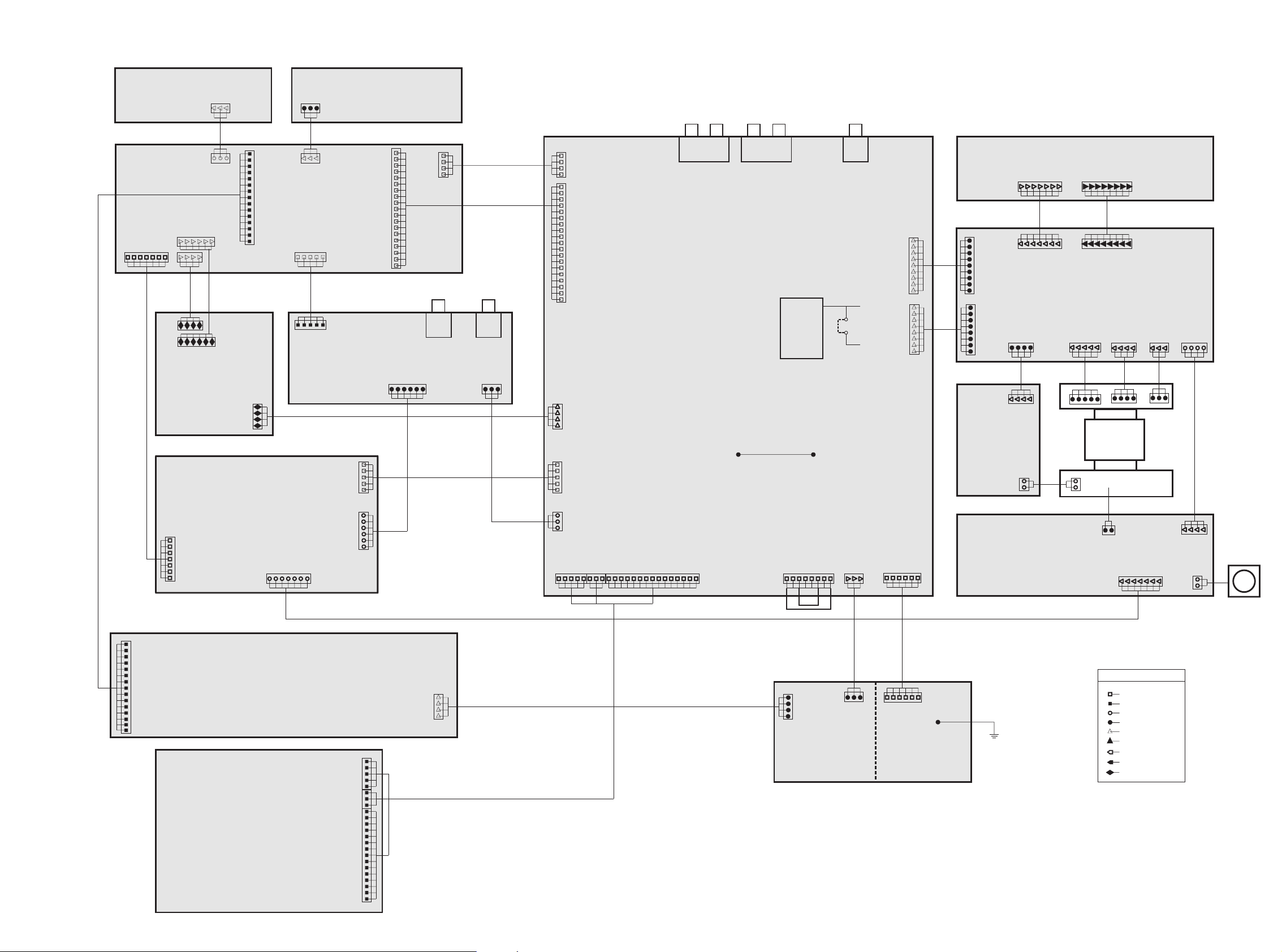
4-14-1
TUNER
ECO 5
TU 95
DIGITAL
IN/OUT
SWITCHING
POWER L/R
Power 5
AMPLIFIER L/R
Power 5
MAINS
Power 5
SUPPLY CDr/w
+5V/-8V/+12V
TRANSFORMER
HEADPHONE
MIC-AMP.
With ALC
Mic Mix
AF-BOARD
Version 7 NON DPL
FRONTBOARD
FW 7/8 R Series
3 CDC KEY
LIGHT GUIDE
CD R/W
CDR MINI 99
CD-CHANGER
3CDC 99 DS
FRONTBOARD 2
CDRM 99 (Design front)
STEREO
STEREO
TU_CLK
TU_CLK
TU_DATA
TU_DATA
ENABLE
ENABLE
MPX
MPX
D-GND
D-GND
+12A
+12A
LEFT_OUT
LEFT_OUT
+5V
+5V
MIC
MIC
LEFT_IN
LEFT_IN
+5V
+5V
FFC SIDE ENTRY
EH TOP ENTRY
EH SIDE ENTRY
DIPMATE
BOARD to BOARD JQ
FFC TOP ENTRY
LEGEND
AA-GND
AA-GND
AA-GND
AA-GND
D_GND
D_GND
A_GND
RIGHT_IN
RIGHT_IN
D_GND
D_GND
D_GND
D_GND
A_GND
Ac1
Ac1 Ac1
FAN
GND
RIGHT_OUT
RIGHT_OUT
+12V
+12V
-8V
-8V
RIGHT_OUT
LEFT_OUT
RIGHT_IN
LEFT_IN
+12A
A_GND
Ac2
Ac2 Ac2
HP_DET
HP_DET
+5V
+5V
CDR_I2C_DA TA
CDR_I2C_DA TA
LED_ON
LED_ON
MIC_KILL
MIC_DET
LED_CLK
LED_CLK
MIC_DET
MIC_KILL
DIG_SW0
DIG_SW0
CDR_I2C_CLK
CDR_I2C_CLK
DATA
DATA
CDR_RESET
CDR_RESET
D_GND
D_GND
D-GND
D-GND
D_GND
D_GND
D_GND
D_GND
JOG_A
JOG_A
JOG_B
JOG_B
CDR_KEY1
CDR_KEY1
CDR_KEY2
CDR_KEY2
JOG_VOL_A
KEY_GND
JOG_VOL_B
JOG_VOL_B
JOG_VOL_A
KEY_GND
D_GND
D_GND
LED_STR
LED_STR
DIG_SW1
DIG_SW1
DIG_SW2 DIG_SW2
D-GND
D-GND
UP_CLK
UP_CLK
DQSY
DQSY
SRDT
SRDT
KILL_R/GND
D-GND
SHIELD
SHIELD
EBU_OUT
EBU_OUT
+3V
+3V
KILL_L/GND/OE_L
OE_LATCH
CD_PORE
CD_PORE
D-GND
D-GND
SILD
SILD
CD_SH_DA TA
CD_SH_DA TA
SICL
SICL
CD_SH_CLK
CD_SH_CLK
CD_SH_STR
CD_SH_STR
SW_INFO
SW_INFO
+12M
+12M
D-GND
D-GND
+5V CD
+5V CD
CD_R
CD_R
AA-GND
AA-GND
CD_L
CD_L
LEFT LEFT
A-GND A-GND
RIGHT
EBU_SIGNAL
EBU_SIGNAL
EBU_SIGNAL
EBU_SIGNAL
EBU_SIGNAL
EBU_SIGNAL
EBU_GND
EBU_GND
EBU_GND
EBU_GND
+3V
+3V
SHIELD
SHIELD
SHIELD
SHIELD
SHIELD
ANA_OUT_LEFTANA_IN_LEFT
AA_GNDAA_GND
ANA_OUT_RIGHT
ANA_IN_RIGHT
ANA_IN_RIGHTANA_OUT_RIGHT
ANA_IN_LEFTANA_OUT_LEFT
SHIELD
RIGHT
+12V +12V
PH TOP ENTRY
PH SIDE ENTRY
XH SIDE ENTRY
1
1
1
1
11
1
0041
1
1
21
1521
1537
1533
26
1528
8351 ( 280mm )
AWG 26 / 7p
0012
0011
1351
1354
8004 ( 140mm )
1167
1142
1166
8003 ( 400mm )
AWG 26 / 3p
FFC 26 / 6p
1522
1
1
1
1
1
1
1
1
1
1
1
1
1
23
99
1
1
1
1
1
1
1
1
1
F2
F1
SW_INFO
CD_SH_STR
D_GND
CD_SH_CLK
SICL
CD_SH_DATA
SILD
D_GND
SRDT
DQSY
UP_CLK
D_GND
D_GND
D_GND
D_GND
MIC_DET
MIC_DET
MIC_KILL
MIC_KILL
SA_IN
HP_DET
NTC
D_GND
PWRDWN
I2C_DATA
I2C_CLK
D_GND
+5V6
-30V
1
F2
F1
SW_INFO
CD_SH_STR
D_GND
CD_SH_CLK
SICL
CD_SH_DATA
SILD
D_GND
SRDT
DQSY
UP_CLK
SA_IN
HP_DET
NTC
D_GND
D_GND
PWRDWN
I2C_DATA
I2C_CLK
+5V6
-30V
1
19
1
CDC_KEY
LED
KEY_GND
+5V6
KEY_GND
D_GND
11
0043
1112
8015 ( 280mm )
FFC 4 p
FFC 19 p
8010 ( 140mm )
8009 ( 280mm )
AWG 26 / 5 p
AWG 26 / 6 p
AWG 26 / 4 p
FFC / 23 p
AWG 26 / 4 p
8008 ( 220mm )
8901
Part of
transformer
(140)
2 p
CHAU / 3 p
8007 ( 180mm )
8014 ( 400mm )
8001 (420mm) (Part of 3CDC Module)
8019 ( 140mm )
1104
1538
1526
1525
1527
1536
27
30
1263
(340mm)
8323
5 p
4 p
3 p
(340)
8903
1258
(220)
AWG26
4p
1911
0027
1912
1913
1264
3
13251261
0011
8322
(220mm)
09
10
08
8324
(280)
(280)
8325
8350 (220mm)
AWG26 / 4p
8018
8017
9 p
8 p
AWG26
AWG26
1262
(220mm)
1124
19
1102
8016
3 p
220mm
8020
3 p
0021
1103
140mm
8016
8012
8011
8006
8002
FFC / 15 p
FFC / 7 p
FFC / 5 p
AWG 26 / 4 p
AWG 26 / 6 p
(120mm)
(280mm)
(340mm)
(340mm)
(280mm)
1160
1501
1704
1130
1420
1702
1162-B
1162-A
1163
1164
1106
1105
0042 0042
11
+5V6
+5V6
AB
AB
D-GND
D-GND
PWRDWN
PWRDWN
+12M +12M
-30V -30V
A-GND
A-GND
+12A
+12A
F1
P5
F1
P5
AMP_ON
AMP_ON
STBY
STBY
+12V M
CDR_ON
+12V M
P_GND
CDR_ON
P_GND
P_GND
P_GND
RIGHT RIGHT
CDR_ON
CDR_ON
NTC NTC
AA-GND
AA-GND
LEFT
LEFT
F2 F2
1
11
111
1
1
1
1
1
1
AUX IN
LINE OUT
SUBWOOFER
DIGITAL
IN
DIGITAL
OUT
CDR_REQKBE
CDR_REQKBE
+5V6
+5V6
SHORTCUT
CONNECTOR
or JUMPER on AF7
I2C SHIFTREGISTER
8031
Handsoldered wire on Af7
8030
GND bottom plate
(140 mm)
FAN
(Part of
Powermodule)
Wiring Diagram FW-R8 (2000-02-22)
Wiring Diagram FW-R8
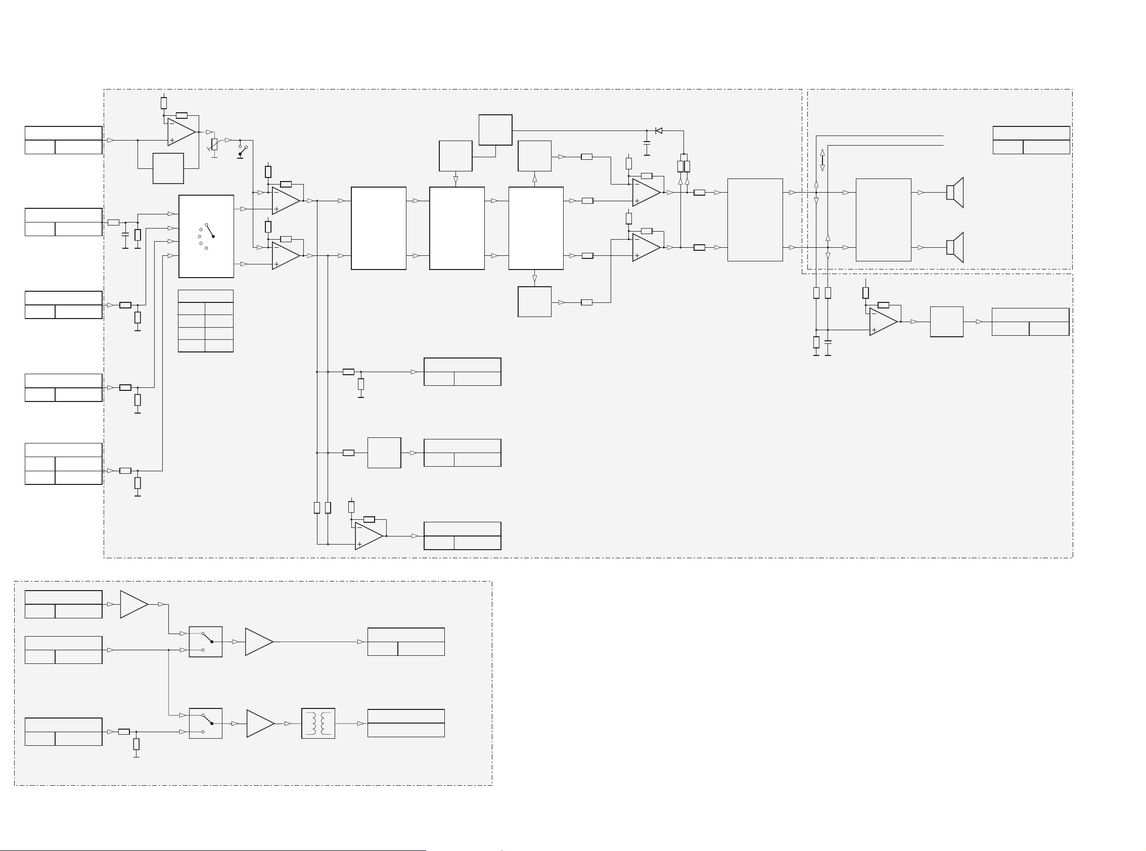
5-1 5-1
Block / Leveldiagram
MIC
Nom.
IN
AUX
MIN
MAX
DS 1
a
b
DS 2
b
a
IS
IS
BASS
ALC
L&R
ALC
CONTROL
SUBWOOFER OUT
0 dB 150 mV
45 dB
SLOW
MUTE 1
45 dB
SLOW
MUTE 2
SOURCE
SELECTOR
Ri=100K
Part of TDA7437
VOLUME I
Part of TDA7437
SOUND
Part of TDA7437
POWER
AMP
MUTE 1
50 dB
SLOW
VOLUME II
FADER
Part of TDA7437
BUFFER
LEVEL
BUFFER
LEVEL
BUFFER
LEVEL
GAIN
AUX
CDR99
3CDC
TU
+2 dB
0 dB
0 dB
0 dB
ALC
MIC
1 mV
TUNER
Nom. 110 mV
3CDC99-DS
Nom. 1000 mV
CDR99
Nom. 1000 mV
CDR99
Nom. 500 mV
Headphone out
0 dB 2800 mV
LINE OUT
Nom. 500 mV
Sectrum analyzer
Nom. 4000 mV
DIGITAL IN
Nom. 500mVpp
3CDC99 Dig. out
Nom. 500mVpp
CDR99 Digital in
Nom. 2000mVpp
Digital out
500mVpp / 75Ω
CDR99 Dig. out
Nom. 500mVpp
2200mV
800 mV
x100
x5
x5
AF 7 Board
for details see
Chapter 8
Power Board
for details see
Chapter 9
Digital switching Board
p
not on all versions

6-1
TABLE OF CONTENTS
Block Diagram .................................................................6-2
3CDC-Key Board
Circuit Diagram ..............................................................6-1
Component Layout.........................................................6-1
Digital Switching Board
Component Layout.........................................................6-1
Circuit Diagram ..............................................................6-3
Light Guide Board
Component Layout.........................................................6-3
Circuit Diagram ..............................................................6-3
Technical Front Board
Component Layout Copperside view.............................6-4
Circuit Diagram ..............................................................6-5
Component Layout Copperside view.............................6-7
Design Front Board
Component Layout.........................................................6-8
Circuit Diagram .............................................................6-9
Microphone Board
Component Layout.......................................................6-10
Circuit Diagram ............................................................6-10
Electrical Partslist ............................................................6-11
Front Board
6-1
1172
1
2
3
100p
2262
3407
10K
1174
DSC
1173
DISC CHANGE
OPEN/CLOSE
3 CDC-Key
3CDC Key Board Copperside view
CDR-Mini 3CDC Key Board Copperside view stage .4 (2000-02-23)
1172
1173
3407
2262
1174
7145
5130
51
3350
16
18
9
16
18
9
7142
9403
9404
9401
1160 1163
1
1
1
2
1162
4
3
3
6
4
3
15
2
4
6
9402
1164
CDR-Mini Digital switch Board Copperside view stage.4 (2000-03-08)
1160 B2
1162 B1
1163 B2
1164 A2
2220 B2
2221 A1
2222 B2
2225 B2
2226 A2
2227 A2
2228 B1
2230 C1
2231 C2
2232 A1
2233 B1
2234 B1
2235 A1
2236 C2
3350 C2
3351 B1
3353 B2
3354 A1
3355 B2
3356 A1
3357 B2
3358 B1
3359 B2
3360 B1
3361 B1
3362 A1
3363 A1
3364 B1
3365 B1
3366 B1
3367 B1
3368 A1
4201 C2
4203 B1
4204 C2
4205 B1
4206 B1
5130 A1
7140 B1
7142 C1
7145 B1
9401 B2
9402 B2
9403 C1
9404 B1
3363
3354
2233
2234
2232
2235
4203
3366
4205
4206
3358
2227
2222
3355
2230
3361
3367
2228
3351
3364
7140
17
814
3365
3359
2221
3368 3356 3362
3357
3353
2225
2236
2231
4204
4201
3360
2220
2226
Digital switch Board Copperside view
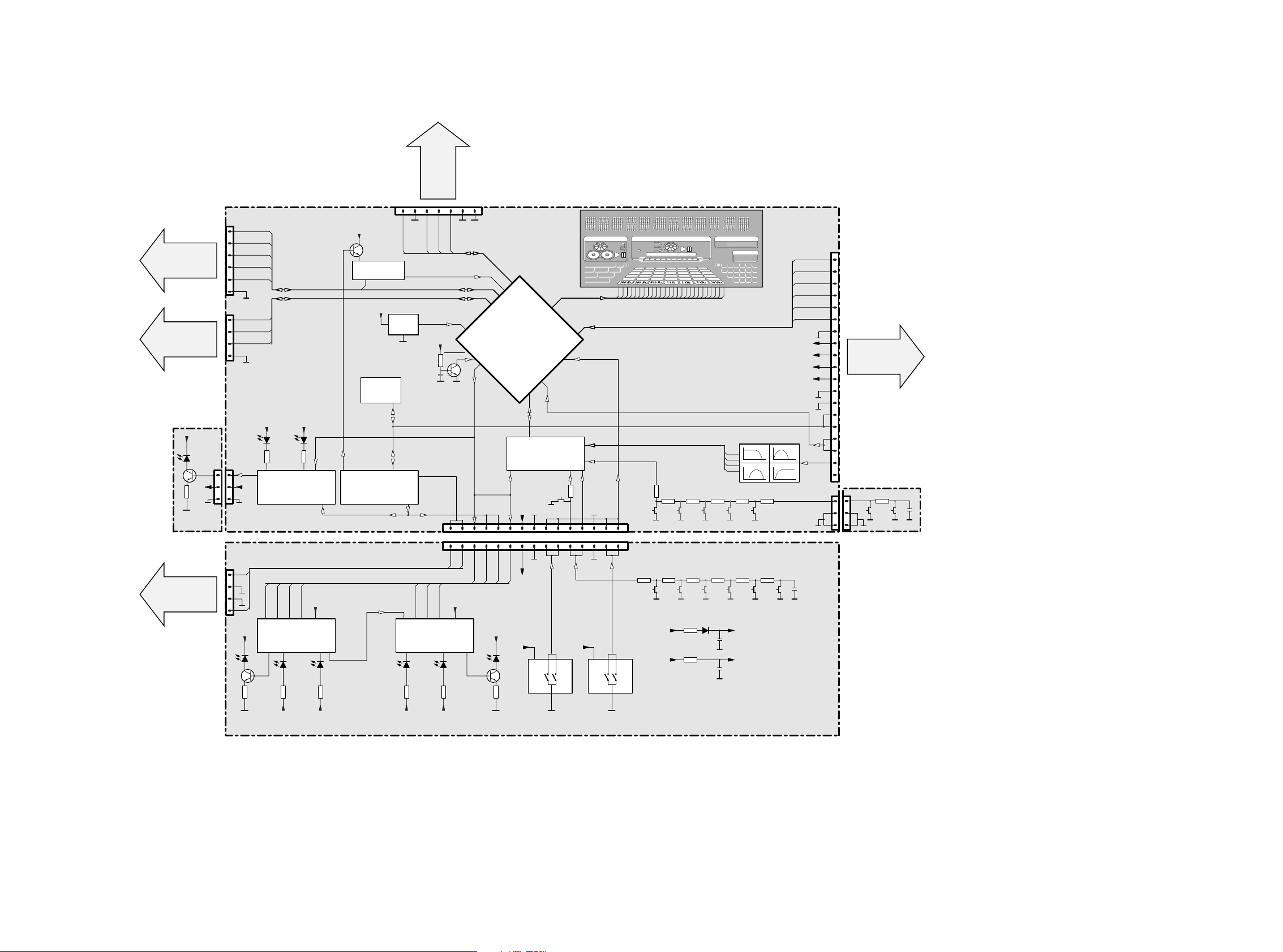
6-2 6-2
CDR-Module
for details see
separate blockdiagram
Chapter 11
TUNER
for details see
separate blockdiagram
Chapter 7
3CDC Module
for details see
separate blockdiagram
Chapter 10
Microphone Board
AF7 Board
for details see
separate blockdiagram
Chapter 8
+5V6
+5V6
0021
1172
3CDC-Key
FRONT BOARD
(Design Front)
7130
74HC4094D
SHIFT REGISTER
7132
74HC4094D
SHIFT REGISTER
+SR +SR
+SR
............
+SR +SR
............
+SR
+SR+SR
LED CLK
LED ON
LED STR
LED CLK
LED ON
LED STR
LED CLK
LED ON
LED STR
DATA
DATA
DATA
KILL
DET
KEY1, KEY2
+5V6 +E
+5V6 +SR
1131
JOG
+E
1134
VOL
+E
0041
1
KILL
DET
Light Guide
FRONT BOARD
(Technical Front)
7112
7110
+D
RC5
2
RESET
1
3
1
19
IR EYE
7121
7123
7111
+D
RDS
RDS DECODER
M24C01
SAA6579T
1124
+5V6
1
1103
1
+5V6
15
1130
1 15
EEPROM
7107
74HC4094D
SHIFT REGISTER
7120
I
2
C_CLK, I2C_DATA
MIC
LED
I
2
C_CLK, I2C_DATA
PWRDWN, AmNTC
M62320FP
I2C SHIFT REGISTER
7122
FREQUENCY FILTER
HEF4051BT
MULTIPLEXER
+5V6
+D
............
+5V6
SA_IN
SA IN
SA1
SA2
SA3
SA4
KEY1
JOG, VOL
KEY2
+5V6
CD BUS
DISPLAY BUS
TUNER BUS
CD TEXT BUS
CD Swinfo
7108
MICROPROCESSOR
TMP88CU77ZF
0043
1102
1
CD ShSTR
CD ShCLK
CD SICL
CD ShDATA
CD SILD
TU CE
TU Data
TU CLK
RDS
RDS
STEREO
F2
F1
-30V
+5V6
0042
1
1
CD TxtIN
CD TxtDQSV
CD TxtCLK
1104
1
1105
I
2
CW_DATA
I
2
CW_CLK
CWReqKbe
CWReset
AM
PM
TIME
TRACKPRESET STEP TOTAL TRACK TIME
CD TEXT EDIT TRACK
TUNERTUNER
REC
PROG ALARM SLEEP
REPEAT SHUFFLE
DISC TRACK ALL
CD RECORDERCD RECORDER
COMPILE CDC
FM TUNER
CD CD AUX
START
FINALIZE
MIC
ALC
FINISH
CD R W
RECORDING IN PROGRESSRECORDING IN PROGRESS
AUXAUX
STEREO
NEWS TA
EON
DIGITAL ANALOG
20 4321
+
1098765
1514131211
19181716
CD CHANGERCD CHANGER
CD R W
INCREDIBLE
SURROUND
LOUDNESS
PURE
AM
PM
TIME
TRACKTOTAL RECREMPRESET STEP TOTAL TRACK TIME
TUNERTUNER
CD RECORDERCD RECORDER
COMPILE CDC
FM TUNER
CD CD AUX
STSTARART
FINALIZE
MIC
ALC
FINISHFINISH
CD R W
RECORDING IN PROGRESS
AUXAUX
STEREO
DIGITAL ANALOG
20 4321
+
1098765
1514131211
19181716
CD CHANGERCD CHANGER
CD R W
INCREDIBLEINCREDIBLE
SURROUNDSURROUND
LOUDNESSLOUDNESS
PUREPURE
Blockdiagram

6-3 6-3
LL
LH
HL
HH
L
H
L
H
LOGIC
LSBMSB
LL
LH
HL
HH
LL
LH
HL
HH
L
H
L
H
LOGIC
LSB MSB
LL
LH
HL
HH
7140-A E6
7140-B D7
7140-C D7
7140-D E7
7140-E E7
7140-F C3
7142 A5
7145 D4
9401 C2
9402 A6
9403 B6
F600 A2
F601 A2
F602 E9
F603 A2
F604 E9
F605 A1
F606 A2
F607 C2
F608 B9
F609 D2
F610 E1
F611 E1
F612 E1
SHIELD
EBU GND
EBU GND
DIGI_IO_SW0
DIGI_IO_SW0
0 CDR Inputmute is off
1106
1 CDR Inputmute is on
C
D
E
F
A
B
C
D
E
F
1160 A1
1162-A E9
1162-B B9
1163 C1
1164 E1
2220 B3
2221 E8
2222 F5
2225 D2
2226 E1
2227 A3
2228 E9
2230 B4
2231 B1
0 CDR Input is Dig-out of 3CDC
1 CDR Input is Dig-In of set
DIGI_IO_SW1
to Front Boardto AF BOARD
DIGI_IO_SW0
DIGI_IO_SW0
P...for Provision only
P
DIG. IN
P
out
123456789
123456789
A
B
1 Dig-output of set is CDR
0 Dig-output of set is 3CDC
mute EBU to CDR:0/1=mute off/mute on
digital in selection:0/1=CDC/AUX
digital out selection:0/1=CDC/CDR
DIGI_IO_SW1
in
140:50
2232 F7
2233 E7
2234 B9
2235 E8
2236 A2
3350 B2
3351 C3
3353 D4
3354 E9
3355 E4
3356 E6
3357 D3
3358 B3
3359 A2
3360 E3
3361 B8
3362 E6
3363 E9
3364 C3
3365 B3
3366 C3
3367 B8
3368 F7
5130 E8
5
6
DIGI_IO_SW1
DIGI_IO_SW0
DIGI_IO_SW0
to CDR
DIG. OUT
EBU IN
EBU_OUT
SHIELD
3
4
5
SXXB-EH-A
1163
1
2
3
4
DIG
FE-ST-VK-N
1160
1
2
2230
100n
ANA
ANA
100K
3366
7140-E
74LVU04D
11 10
+5VA
DIG
3363
270R
+2.5VIC
DIG
DIG
3361
470R
1162-B
YKC21-3421
5
4
3
2231
100n
2225
100n
DIG
3364
100R
DIG
DIG
ANA
DIG
DIG
34
6
3367
82R
ANA
5130
6RG
1
2
+2.5VIC
220R
3359
EH-S
1
2
3
2228
100n
1164
1n
2232
2222
100n
98
3360
100K
470R
3362
DIG
7140-D
ANA
2235
150p
ANA
3368
560R
7140-B
3
14
4
VDD
16
VEE7VSS
8
10K
3351
DIG
HEF4052B
7142
1
10
11
12
13
14
15
23
4
5
6
9
+2.5VIC
10K
3358
3353
56K
DIG
3350
470R
+5VA
4
5
6
916
VDD
7
VEE
8
VSS
100n
2221
7145
HEF4052B
1
10
11
12
13
14
15
23
13
12
1u
2227
2
DIG
7140-F
7140-A
1
100n
2220
3356
2K2
3365
100K
9402
+5VA
+2.5VIC
9401
+2.5VIC
100n
2234
39R
3354
100n
2233
100n
2226
100n
2236
5
2
1
1162-A
YKC21-3421
DIG
3357
68K
100K
3355
9403
6
7140-C
5
+5VA
Digital switch Board
5,6V
5,6V
2,5V
5,6V
1,3V
1,1V
1,1V
1,2V
1,2V
DC Voltages measured
during operation
.
. . V
EVM
V
CDR-Mini LED Board Copperside view stage .4 (2000-02-23)
Light Guide Copperside view
0021
4501
3403
7160
6170
BE
C
3401
2260
3404
BC847B
7160
0021
1
2
3
6170
LTL-503
3403
1K
3401
2K7
47R
3404
2260
100n
Light Guide Board
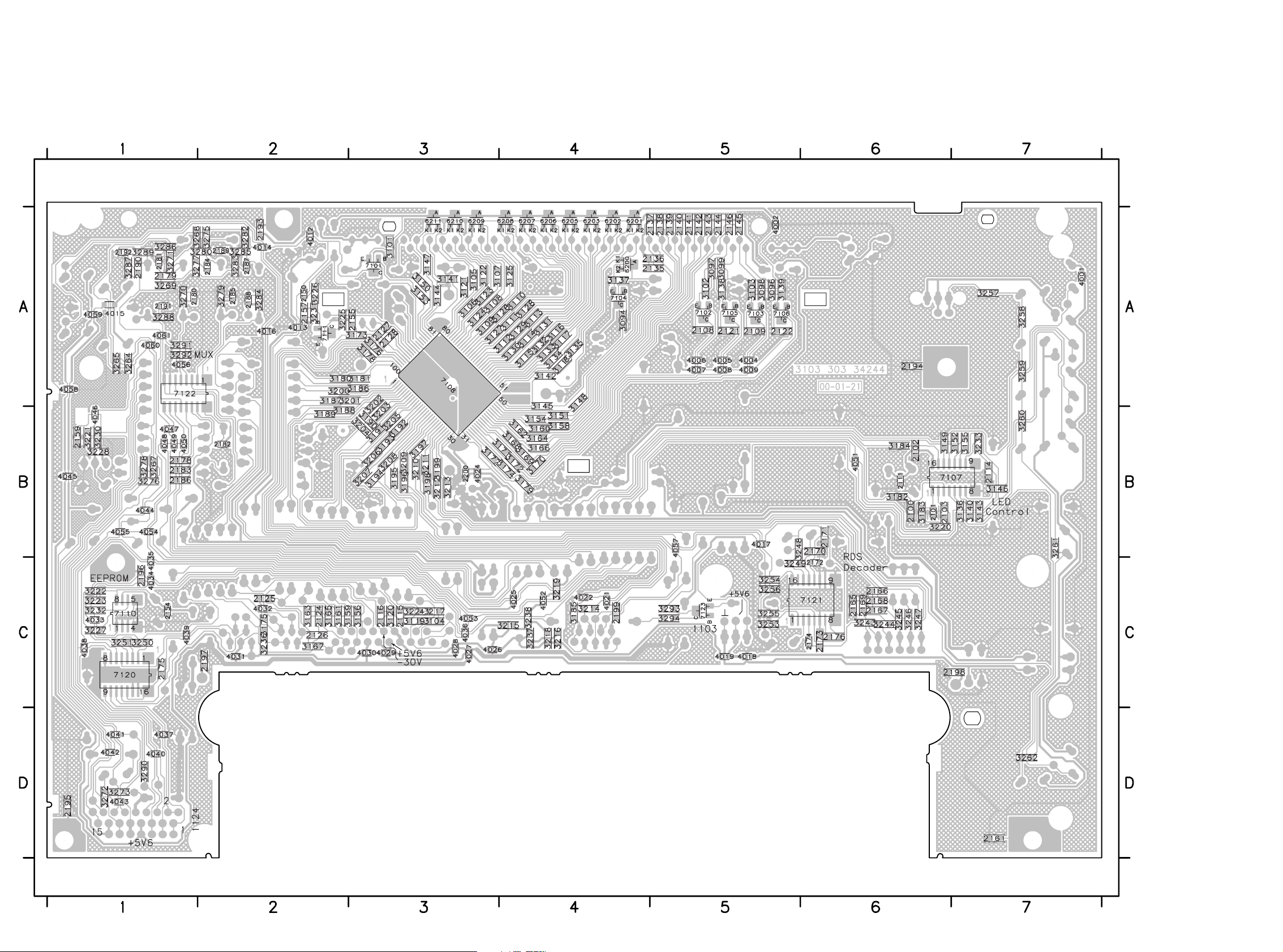
6-4 6-4
CDR-Mini Front Board Copperside view stage .4 (2000-02-23)
This assembly drawing shows a summary of all possible versions.
For components used in a specific version see schematic diagram respectively partslist.
2100 B6
2101 B6
2102 B6
2103 B6
2108 A5
2109 A5
2111 B6
2114 B7
2115 C3
2116 C3
2121 A5
2122 A5
2124 C2
2125 C2
2126 C2
2127 A3
2128 A3
2135 A5
2136 A5
2137 A5
2138 A5
2139 A5
2140 A5
2141 A5
2142 A5
2143 A5
2144 A5
2145 A5
2146 A5
2150 A2
2154 C1
2155 A3
2157 A2
2159 B1
2161 D7
2165 C6
2166 C6
2167 C6
2168 C6
2169 C6
2170 B6
2171 B6
2172 C6
2173 C6
2174 C6
2175 C1
2176 C6
2178 B1
2179 A1
2180 A1
2181 A1
2182 B2
2183 B1
2184 A2
2185 A2
2186 B1
2187 A2
2188 A2
2189 A2
2190 A1
2191 A1
2192 A1
2193 A2
2194 A6
2195 D1
2196 C1
2197 C2
2198 C7
2199 C4
2200 B3
3094 A4
3096 A5
3097 A5
3098 A5
3099 A5
3101 A3
3102 A5
3103 A5
3104 C3
3105 A3
3106 A3
3107 A3
3108 A3
3109 A3
3110 A4
3111 A4
3112 A4
3113 A4
3114 A4
3115 A4
3116 A4
3117 A4
3118 A4
3119 C3
3120 C3
3121 A3
3122 A3
3123 A3
3124 A3
3125 A4
3126 A4
3127 A3
3128 A4
3129 A4
3130 A4
3131 A4
3132 A4
3133 A4
3134 A4
3135 A4
3136 B7
3137 A4
3138 A5
3139 A5
3140 B7
3141 A3
3142 A4
3143 B7
3144 A3
3145 A4
3146 B7
3147 A3
3148 A4
3149 B6
3150 A3
3151 B4
3152 B7
3153 A3
3154 B4
3155 B7
3156 C3
3158 B4
3159 C2
3160 B4
3161 C2
3162 B4
3163 C2
3164 B4
3165 C2
3166 B4
3167 C2
3168 B4
3169 B4
3170 B4
3171 B4
3172 B4
3173 A3
3174 B4
3175 C2
3176 A3
3177 B3
3178 A3
3179 B4
3180 A2
3181 A3
3182 B6
3183 B6
3184 B6
3185 C4
3186 A3
3187 A2
3188 B2
3189 B2
3190 B3
3191 B3
3192 B3
3193 B3
3194 B3
3195 B3
3196 B3
3197 B3
3198 B3
3199 B3
3200 A2
3201 A3
3202 A3
3203 B3
3204 B3
3205 B3
3206 B3
3207 B3
3208 B3
3209 B3
3210 B3
3211 B3
3212 B3
3213 B3
3214 C4
3215 C4
3216 C4
3217 C3
3218 C4
3219 C4
3220 B6
3221 B1
3222 C1
3223 C1
3224 C3
3225 A2
3226 A2
3227 C1
3228 B1
3230 B1
3231 A2
3232 C1
3233 B7
3236 C2
3237 C4
3238 C4
3243 C6
3244 C6
3245 C6
3246 C6
3247 C6
3248 B5
3249 C5
3250 C1
3251 C1
3253 C5
3254 C5
3255 C5
3256 C5
3257 A7
3258 A7
3259 A7
3260 B7
3261 B7
3262 D7
3264 A1
3265 A1
3267 B1
3268 A1
3269 A1
3270 A1
3271 A1
3272 D1
3273 D1
3275 A2
3276 B1
3277 A1
3278 B1
3279 A2
3280 A2
3282 A2
3283 A2
3284 A2
3285 A2
3286 A1
3287 A1
3288 A1
3289 A1
3290 D1
3291 A1
3292 A1
3293 C5
3294 C5
4001 A7
4002 A5
4004 A5
4005 A5
4006 A5
4007 A5
4008 A5
4009 A5
4012 A2
4013 A2
4014 A2
4015 A1
4016 A2
4017 B5
4018 C5
4019 C5
4021 C4
4022 C4
4024 B3
4025 C4
4026 C3
4027 C3
4028 C3
4029 C3
4030 C3
4031 C2
4032 C2
4033 C1
4034 C1
4035 C1
4036 C3
4037 D1
4038 C1
4039 C1
4040 D1
4041 D1
4042 D1
4043 D1
4044 B1
4045 B1
4046 B1
4047 B1
4048 B1
4049 B1
4050 B1
4051 B6
4052 C4
4053 C3
4054 B1
4055 B1
4056 A1
4057 B5
4058 A1
4059 A1
4060 A1
4061 A1
6200 A4
6201 A4
6202 A4
6203 A4
6205 A4
6206 A4
6207 A4
6208 A4
6209 A3
6210 A3
6211 A3
7101 A3
7102 A5
7103 A5
7104 A4
7105 A5
7106 A5
7107 B6
7108 A3
7110 C1
7111 A2
7120 C1
7121 C6
7122 A1
7123 C5
Front Board Copperside view
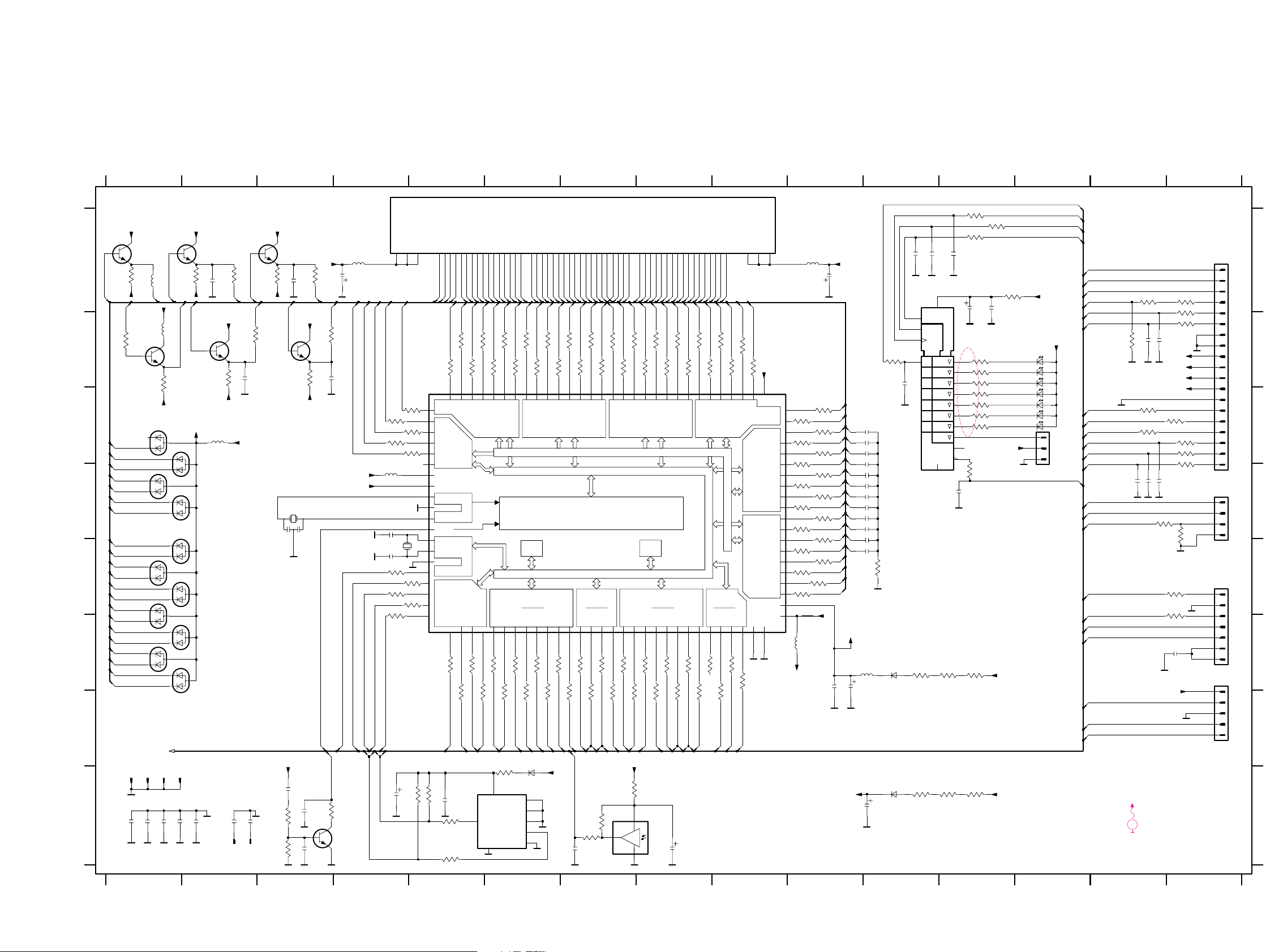
6-56-5
RAM
VFT - DRIVER - CIRCUIT
VFT - DRIVER
3-STATE
I/O
ROM
3-STATE
I/O
P1 P3
3-STATE
I/O
3-STATE
I/O
P4 P5
ANALOG IN ANALOG IN
I/O
ADRESS / DATA - BUS
PE
VFT - DRIVER
P0
PD
VFT - DRIVER
P9
VFT - DRIVER
P8
VFT - DRIVER
P7
VFT - DRIVER
P6
VFT - DRIVER
PF
CPU - CLK
I/O P2
CPU
STB
D1
EN1
SRG8
FRONT BOARD SHEET 1
DATA BUS TO SHEET 2
H
1 2 3 4 5 6 7 8 9 101112131415
1 2 3 4 5 6 7 8 9 101112131415
A
B
C
D
E
F
G
H
A
B
C
D
E
F
G
(1160)
(1538)
(1704)
to Digital switching
to CDR-Module
to AF-BOARD
to AF-BOARD
12x
EEPROM
7x
12x
(1536)
IR-EYE
D
1K
3192
6104
3161
1K
10p 2116
LTL-1CHAE
6107
1n
2194
82K
3102
D
3195
1K
2u2
5111
D
D
D
100p
2100
6108
100R
3178
2140
1N4148
1K
3209
0404
6101
1K
3095
6102
3199
1K
270R
3140
2u2
5104
1K3163
6105
2111
100n
8
9
4R7
3216
220R
3123
10
11
12
13
14
15
16
17
18
19
2
3
4
5
6
7
FE-BT-VK-N
1102
1
D
2u2
5101
10p2126
3132
220R
53545556575859606162666870 9383940414243444546474849 5505152 23242526272829 33031323334353637
1101
110111213141516171819202122
6110
1N4148
BJ721GNK
D
1108
3145
470R
D
220u
2134
7105
BC847B
220u
2151
D
2146
3143
270R
220R
3106
D
100n
2150
D
BC847B
7111
3151
220R
6211
6210
3134
220R
D
3122
220R
3
4
D
FE-BT-VK-N
1104
1
2
1K
3203
2197
1n
2141
3155270R
D
3214
100R
3159
3232
1K
100R
3233
470R
2121
220R
3148
180p
10n
2155
220R
3158
D
D
10n
2157
2161
1n
D
D
3206
1K
47R
3235
3187
1K
D
180p
2135
D
2138
220R
3142
PF3
85
PF4
86
92
RESET
TEST
95
31
VAREF
VASS
30
VDD-CPU
88
VDD-I|O
32
VDD-VFT
51
VKK
87
90
VSS-CPU
VSS-I|O
29
XIN
89
XOUT
91
PD369PD4
7071
PD5
PD6
7273
PD7
PE0
74
PE175PE276PE377PE4
7879
PE5
PE6
80
PE7
81
PF0
82
PF1
83
PF2
84
P8353P84
5455
P85
P86
5657
P87
P9058P9159P9260P9361P94
6263
P95
P9664P97
65
PD066PD167PD2
68
P63
36
P64
37
38
P65
P66
39
40
P67
P70
41
P71
42
P72
43
P73
44
P74
45
46
P75
P76
47
P77
48
P80
49
P81
50
P82
52
P3316P40
17 18
P41
P42
19 20
P43
P4421P4522P4623P4724P50
25 26
P51
P5227P53
28
P60
33
P61
34
P62
35
P063P0745P10
P1167P12
P138P149P1510P1611P17
12
96
P20
P21
93
P22
94
P3013P3114P32
15
7108
TMP88CU77ZF
97
P00
P01
98
P02
99
P03
100
P041P05
2
3228
D
6209
10K
EH-B
1103
1
2
3
220R
3147
7112
TSOP2836
3
GND4MT
1
OUT
2
VSUP
3182
470R
1K
3198
3220
100R
1107
32K768
D
4R7
3218
3130
220R
220R
3135
3176
100R
3231
100K
3177
1K
7101
BC847B
D
220R
3113
3173
1K
D
shield5
3165 470R
D
3212
1K
2144
3210
1K
3237
4R7
4R7
3238
3097
470R
1K
3194
3128
220R
0405
3136 270R
D
BAW56
6200
D
1K
3179
680K
3217
6201
100R
3234
82K
3139
5102
2u2
3185
100R
D
1K3167
3221
100R
3114
220R
3107
220R
3150
220R
220R
3125
220R
3121
D
3119
220R
D
6203
10p2115
2u2
5112
6205
3149
270R
0401
D
5103
2u2
6207
220R
3168
1105
FE-BT-VK-N
1
2
3
4
5
6
7
180p
2108
D
3108
220R
220R
3117
100n2154
D
3174
1K
3154
220R
15p
220R
3144
shield1
2128
2101
100n
680K
3224
D
2136
220R
3120
VSS
WC_
7
470R
3099
2142
M24C01
7110
E0
1
E1
2
E2
3
SCL
6
SDA
5
VCC
8
4
2145
470R
3098
270R
3152
3186
D
3096
470R
2n2
2159
1K
3110
220R
1K
3230
D
3126
220R
3181
1K
220R
3166
470R
3094
1K
3201
D
3193
1K
2139
4
5
D
D
220R
3171
3197
1K
FE-BT-VK-N
1106
1
2
3
3215
4R7
3138
82K
1K
3207
10K3222
2153
1u
KEY
3223
10K
10u
2152
2102
10n
2193
1n
1n
2103
14
13
12
11
9
10
1
16
8
3204
1K
74HC4094D
7107
3
2
15
4
5
6
7
2122
220R
3127
4K7
3137
180p
1K
3190
3118
220R
3219
4R7
220R
3160
3170
220R
3105
220R
3208
1K
D
D
0406
D
220R
3115
3164
220R
shield4
D
3202
1K
D
3236
33K
3184
1K5
82K
1K5
3183
3175
D
3103
1K
2110
3200
1K
47u
2137
3226
100K
1K
3172
1n
2196
6103
220R
1K
3188
1n
2198
3104
D
D
D
1K
3180
3191
470R
2143
220R
3109
3116
220R
2125
1K
3211
2u2
5109
10p
3141
220R
3101
4K7
BC847B
7102
shield3
3124
220R
220R
3129
6208
BC847B
7104
2109
180p
212715p
3169
220R
BC847B
7103
2200
100n
1K
3196
6109
1N4148
220R
3131
1K
3205
6202
0403
3153
1K
1K
3225
220R
3133
220R
3111
6106
1K
0402
3112
220R
3227
D
5110
2u2
2124 10p
2199
10n
470p
2114
shield2
3189
470R
1n
D
2195
47u
3162
220R
D
2158
6206
270R3146
10u
2156
D
7106
BC847B
1K
3213
G11
G8
G5
G2
G10
G7
G4
G1
CDSwInfo
-30V
+5V6
F2
F1
AmNTC
SA_IN
1K
3156
P32
P33
P26
P30
P22
P25
P18
P19
P12
P13
P10
P11
P14
P16
P6
P7
P4
P5
P2
P3
P1
-30V!
I2C_DATA
I2C_CLK
LEDShDATA
G12
G9
G6
G3
LEDShDATA
LEDShSTR
LEDShCLK
LED_ON
+yP
+yP
+yP
RESET
G16
G14
G151
G131
G161
G141
P361
P36
-30V
+D
PWRDWN
I2C_CLK
I2C_DATA
-30V
P24
P25
P26
P27
P28
P29
P30
P31
P32
P33
P34
+5V6
+yP
+5V6
CDSICL
I2CW_DATA
I2CW_CLK
G15
G13
P35
+D
+C
DIGI_IO_SW2
+D
P13
P14
P15
P16
P17
P351
G161
G151
G141
G131
G12
G11
G10G9G8G7G6G5G4G3G2G1P361
P1
P18
P19
P20
P21
P22
P23
+D
P351
CDTXTin
CdTxtDQSV
DIGI_IO_SW0
DIGI_IO_SW1
+5V6
CDShCLK
CDShSTR
P2P3P4P5P6P7P8P9P10
P11
P12
P31
P32
P33
P34
P35
P13
P29
P27
P25
P23
P21
P19
CDShCLK
-30V!
+5V6
+5V6
-30V!
RC5
+D
CDShDATA
CDSILD
HP_DET
RESET
+D
CWReqKbe
CWReset
+5V6
CDShDATA
+D
-30V!
-30V!
+D
-30V!
+D
-30V!
P20
P22
P24
P26
P28
P30
P15
P14
P12
P11
P10
P9P8P7P6P5P4P3
P2
JOG_VOLB
I2CW_CLK
I2CW_DATA
TU_DATA
JOG_B
LEDShCLK
F2F1
I2C_DATA
I2C_CLK
CWReqKbe
CWReset
TuRDSDATA
STEREO
TU_CLK
TU_CE
G16
G15
G14
G13
G12
G11
G10
G9
G8
G7
G6
G5
G4
G3
G2
G1
P18
P17
P16
CDTXTCLK
P1
P36
Sh_DATA
+5V6
JOG_VOLA
RC5
CDTXTDQSV
JOG_A
CDSwInfo
TuRDSCLK
CDShSTR
CDSICL
CDTXTCLK
CDTXTin
CDSILD
PWRDWN
AmNTC
Multiplexin
MuxEnable
0401 G1
0402 G1
0403 G1
0404 G2
0405 H2
0406 H2
1101 A9
1102 A15
1103 D13
1104 D15
1105 E15
1106 F15
1107 E4
1108 D3
2100 A12
2101 A11
2102 A11
2103 B11
2108 A2
2109 A3
2110 A12
2111 A12
2114 D12
2115 B14
2116 B14
2121 B2
2122 B3
2124 D14
2125 D14
2126 D14
2127 E4
2128 E4
2134 G10
2135 C11
2136 C11
2137 C11
2138 C11
2139 D11
2140 D11
2141 D11
2142 D11
2143 D11
2144 D11
2145 D11
2146 E11
2150 H3
2151 H11
2152 A4
2153 H4
2154 H5
2155 H3
2156 A10
2157 H3
2158 H8
2159 H7
2161 H1
2193 H1
2194 H1
2195 H1
2196 H2
2197 H2
2198 H2
2199 F15
2200 F10
3094 B1
3095 E11
3096 B3
3097 A2
3098 A3
3099 B2
3101 A1
3102 A2
3103 A3
3104 A15
3105 B5
3106 B5
3107 B6
3108 B6
3109 B6
3110 B7
3111 B7
3112 B7
3113 B7
3114 B8
3115 B8
3116 B8
3117 B9
3118 B9
3119 A15
3120 B15
3121 B5
3122 B5
3123 B6
3124 B6
3125 B6
3126 B6
3127 B7
3128 B7
3129 B7
3130 B8
3131 B8
3132 B8
3133 B8
3134 B9
3135 B9
3136 B12
3137 B1
3138 B2
3139 B3
3140 B12
3141 C5
3142 C10
3143 B12
3144 C4
3145 C10
3146 C12
3147 C5
3148 C10
3149 C12
3150 C4
3151 C10
3152 C12
3153 C5
3154 C10
3155 C12
3156 C14
3158 C10
3159 C15
3160 D10
3161 C14
3162 D10
3163 C15
3164 D10
3165 C15
3166 D10
3167 D15
3168 D10
3169 D10
3170 D10
3171 E10
3172 E10
3173 E4
3174 E10
3175 D14
3176 E5
3177 E10
3178 E4
3179 E10
3180 E5
3181 E4
3182 A12
3183 A12
3184 A12
3185 E15
3186 F5
3187 F5
3188 F6
3189 F6
3190 F6
3191 F7
3192 F7
3193 F7
3194 F7
3195 F8
3196 F8
3197 F8
3198 F9
3199 F9
3200 G5
3201 G6
3202 G6
3203 G6
3204 G6
3205 G7
3206 G7
3207 G7
3208 G8
3209 G8
3210 G8
3211 G8
3212 G9
3213 F9
3214 E15
3215 F11
3216 F12
3217 A14
3218 H12
3219 H11
3220 B11
3221 H8
3222 H5
3223 H5
3224 B14
3225 H4
3226 H3
3227 H5
3228 H7
3230 H7
3231 H3
3232 H5
3233 D12
3234 H6
3235 A12
3236 D15
3237 F12
3238 H12
5101 C2
5102 F10
5103 D4
5104 F11
5109 A4
5110 A10
5111 A1
5112 B1
6101 B13
6102 B13
6103 B13
6104 C13
6105 C13
6106 C13
6107 C13
6108 F11
6109 H6
6110 H11
6200 C1
6201 C1
6202 D1
6203 D1
6205 E1
6206 E1
6207 E1
6208 E1
6209 F1
6210 F1
6211 F1
7101 A1
7102 A2
7103 A3
7104 B1
7105 B2
7106 B3
7107 A11
7108 D6
7110 H6
7111 H3
7112 H8
DISPLAY
DC Voltages measured
during operation
.
. . V
EVM
V
-27,7V
-27,8V
4,6V
-27,7V
-27,8V
4,6V
-27,7V
-27,8V
4,6V
-27,7V
-27,8V
4,6V
-27,7V
-27,8V
-30V
4,5V
4,5V
5,5V
4,5V
4,5V
4,5V
5,6V
5,6V
4,6V
4,5V
4,5V
5V
4,4V
0V
4,6V
-27,7V
-27,8V
4,6V
0V = LED on
5V = LED off
 Loading...