

Philips FWM-417, FWM-417-X Service Manual
MP3 Mini Hi-Fi System
�
FWM417X/78
FWM417/55
CONTENTS
Technical specification ..................................................................1-2
Service measurement setup..........................................................1-3
Service aids .................................................................................1-4
Instructions on CD playability ................................................2-1..2-2
Block diagram ................................................................................3-1
Wiring diagram ..............................................................................4-1
Disassembly diagram............ ................................................5-1..5-2
Main board
Circuit diagram ..................................................................6-1..6-2
Layout diagram ..................................................................6-3..6-4
Display board
Circuit diagram .........................................................................7-1
Layout diagram ..................................................................7-2..7-3
CD board
Circuit diagram .........................................................................8-1
Layout diagram ..................................................................8-2..8-3
MCU board
Circuit diagram .........................................................................9-1
Layout diagram .........................................................................9-2
Tuner Board
Circuit diagram. ......................................................................
Layout diagram .......................................................................
Power Board
Circuit diagram. ......................................................................
Layout diagram .......................................................................
HF Board
Circuit diagram. ......................................................................
Layout diagram .......................................................................
Exploded view diagram ...............................................................13-1
Mechanical parts list ...........................................................13-2..13-3
Electrical parts list...............................................................14-1..14-2
10-1
10-2
11-1
11-2
12-1
12-2
©
Copyright 2009 Philips Consumer Electronics B.V. Eindhoven, The Netherlands
All rights reserved. No part of this publication may be reproduced, stored in a retrieval
system or transmitted, in any form or by any means, electronic, mechanical, photocopying,
or otherwise without the prior permission of Philips.
Published by LX 0919 Service Audio Subject to modification
Version 1.0
3141 785 34070

Tuner
Tuning range FM: 87.5 - 108MHz;
AM: 531 - 1602kHz
(9KHz); 530 - 1700KHz
(10KHz)
Tuning grid 100KHz (FM);
9KHz/10KHz (AM)
Number of presets 40 (FM + AM)
FM 75ohm wire
AM loop antenna
Speakers
Speaker Impedance 6ohm
Woofer 2 x 5.25”
Tweeter 2 x 1.75”
Dimensions
(W x H x D)
249 x 344 x 250mm
Weight 3.58kg each
General information
AC power 110 - 127/220 - 240V,
50/60Hz
Operation power
consumption
180W
Standby power
consumption
<2W
USB direct Version 2.0/1.1
Dimensions
Main Unit
(W x H x D)
265 x 310 x 403mm
Weight
(without speakers)
6.09kg
Amplifier
Total output power 280W RMS
Frequency response 60 - 16kHz
Signal-to- noise ratio >67dB A (IEC)
Aux input 1500mV/2000mV
Disc
Laser type Semiconductor
Disc diameter 12cm/8cm
Support disc CD-DA, CD-R,
CD-RW, MP3-CD,
WMA-CD
Audio DAC 24Bits / 44.1kHz
Total harmonic
distortion
<1.5%
Frequency response 60Hz -16kHz (44.1kHz)
S/N ratio >75dBA
TECHNICAL SPECIFICATION
1 - 2
e
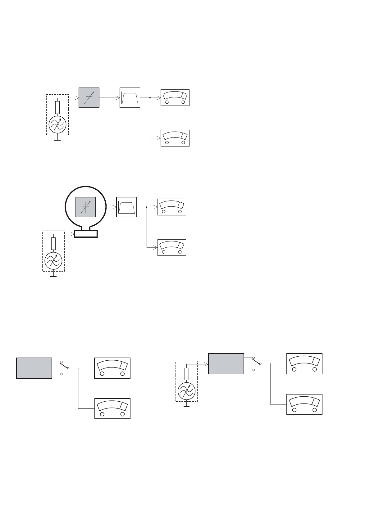
MEASUREMENT SETUP
Tuner FM
1-3
Bandpass
LF Voltmeter
e.g. PM2534
RF Generator
e.g. PM5326
DUT
250Hz-15kHz
e.g. 7122 707 48001
Ri=50:
S/N and distortion meter
e.g. Sound Technology ST1700B
Use a bandpass filter to eliminate hum (50Hz, 100Hz) and disturbance from the pilottone (19kHz, 38kHz).
Tuner AM (MW,LW)
RF Generator
e.g. PM5326
Ri=50:
DUT
Frame aerial
e.g. 7122 707 89001
Bandpass
250Hz-15kHz
e.g. 7122 707 48001
LF Voltmeter
e.g. PM2534
S/N and distortion meter
e.g. Sound Technology ST1700B
To avoid atmospheric interference all AM-measurements have to be carried out in a Faraday´s cage.
Use a bandpass filter (or at least a high pass filter with 250Hz) to eliminate hum (50Hz, 100Hz).
CD
Use Audio Signal Disc
(replaces test disc 3)
DUT
L
R
SBC429 4822 397 30184
S/N and distortion meter
e.g. Sound Technology ST1700B
LEVEL METER
e.g. Sennheiser UPM550
-
Recorder
Use Universal Test Cassette CrO2 SBC419 4822 397 30069
or Universal Test Cassette
LF Generator
e.g. PM5110
Fe SBC420 4822 397 30071
DUT
L
R
S/N and distortion met
e.g. Sound Technology ST170
LEVEL METER
e.g. Sennheiser UPM550
with FF-filter
SERVICE AIDS
1-4
GB
All ICs and many other semi-conductors are
susceptible to electrostatic discharges (ESD).
Careless handling during repair can reduce life
drastically.
When repairing, make sure that you are
connected with the same potential as the mass
of the set via a wrist wrap with resistance.
Keep components and tools also at this
potential.
WARNING
GB
Safety regulations require that the set be restored to its original
condition and that parts which are identical with those specified,
be used
Safety components are marked by the symbol
!
.
ESD
CLASS 1
LASER PRODUCT
Lead free
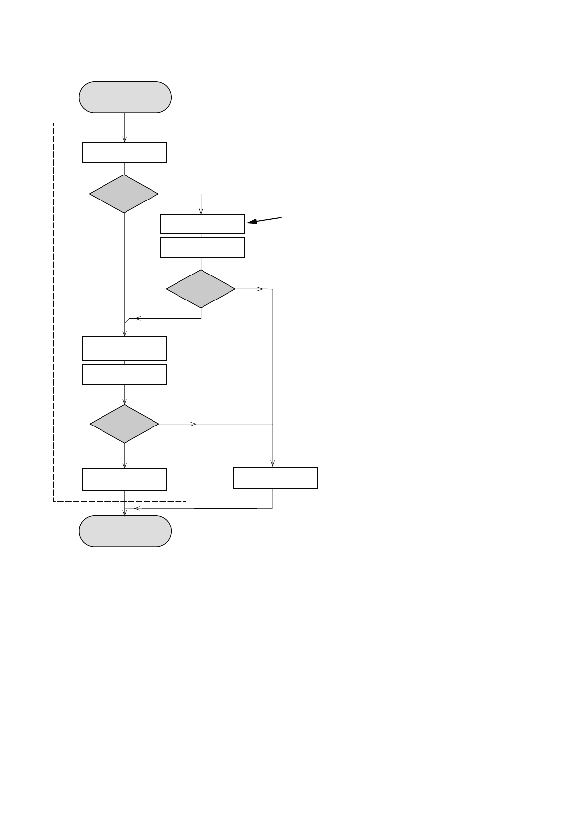
INSTRUCTIONS ON CD PLAYABILITY
Customer complaint
"CD related problem"
Set remains closed!
check playability
1
2 - 1
playability
ok ?
Y
Play a CD
for at least 10 minutes
check playability
playability
ok ?
Y
N
"fast" lens cleaning
check playability
playability
ok ?
N
3
N
Y
For flap loaders (= access to CD drive possible)
cleaning method
4 is recommended
add Info for customer
"SET OK"
2
return set
1 - 4 For description - see following pages
Exchange CDM
INSTRUCTIONS ON CD PLAYABILITY
2 - 2
1
PLAYABILITY CHECK
For sets which are compatible with CD-RW discs
use CD-RW Printed Audio Disc ....................7104 099 96611
TR 3 (Fingerprint)
TR 8 (600µ Black dot) maximum at 01:00
• playback of these two tracks without audible disturbance
playing time for: Fingerprint
Black dot from 00:50 to 01:10
• jump forward/backward (search) within a reasonable time
For all other sets
use CD-DA SBC 444A..................................4822 397 30245
TR 14 (600µ Black dot) maximum at 01:15
TR 19 (Fingerprint)
TR 10 (1000µ wedge)
• playback of all these tracks without audible disturbance
playing time for: 1000µ wedge 10seconds
Fingerprint 10seconds
Black dot from 01:05 to 01:25
• jump forward/backward (search) within a reasonable time
10seconds
4
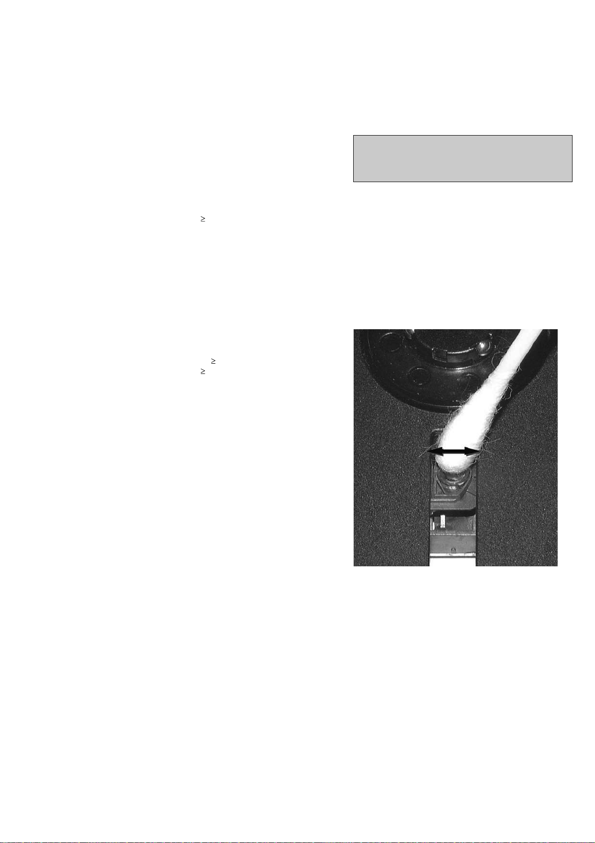
LIQUID LENS CLEANING
Before touching the lens it is advised to clean the
surface of the lens by blowing clean air over it.
This to avoid that little particles make scratches on
the lens.
Because the material of the lens is synthetic and coated
with a special anti-reflectivity layer, cleaning must be done
with a non-aggressive cleaning fluid. It is advised to use
“Cleaning Solvent
The actuator is a very precise mechanical component and
may not be damaged in order to guarantee its full function.
Clean the lens gently (don’t press too hard) with a soft and
clean cotton bud moistened with the special lens cleaner.
The direction of cleaning must be in the way as indicated in
the picture below.
2
CUSTOMER INFORMATION
It is proposed to add an addendum sheet to the set which
informs the customer that the set has been checked
carefully - but no fault was found.
The problem was obviously caused by a scratched, dirty or
copy-protected CD. In case problems remain, the customer
is requested to contact the workshop directly.
The lens cleaning (method 3) should be mentioned in the
addendum sheet.
The final wording in national language as well as the printing
is under responsibility of the Regional Service Organizations.

SET BLOCK DIAGRAM
3-1 3
-1
TUNER
SI4730/31
USB
RTC
HT1381
16M
SDRAM
8M NOR
FALSH
RC
SENSOR
RC5/RC6 CODE
IIC
3CDC MOTOR
DRIVER
TDA7073A
MOTOR DRIVER
BA5826
PICK UP
PICK UP
DA11
DA11
MOTOR
MOTOR
CONTR OL DAT A
CD SERVO
BU9543
IIC
BX8800
CD PCM BCK, LRCK,DATE
I/O
Expand IC
74HC4094
*3
-
PCM BCK ,LRCK ,DATE PCM
CD PCM
MUX
74LVC157
ADC
WM8782
CD L/R
LCD
DRIVER
E T8862
LCD
KEY PART
IIC
TUNER L/R
FUNCTION IC
TDA7468D
INPUT
AUX
AUDIO L&R
INPUT
MICRO
PHONE
MAIN L/R
AMPFILER
STK-433-
090E(SANYO)
AMPFILER
STK-433-
090E(SANYO)
FL
FR
SL
SR

SET WIRING DIAGRAM
4-1
4-1
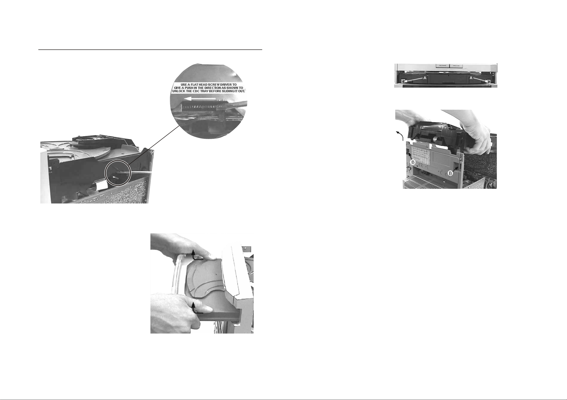
DISMANTLING INSTRUCTIONS
Dismantling of the CDC Module and Front Panel
5-1
5-1
1) Loosen 4 screws to remove the Cover Top of the set.
2) Loosen 2 screws to remove the Panel Left and 2 screws to
remove the Panel Right of the set.
3) Slide out the CDC Tray as shown in the diagram below with
the help of a flat head screw driver.
5) Loosen 2 screws A and 2 screws B to remove the CDC
Module as indicated.
6) Remove 2 screws at the bottom to separate the
Front Panel Assembly from the Plate Bottom.
Front View CDC
Sliding Out The CDC Tray
Remove CDC Module
4) Remove the Cover Tray CDC as indicated.
Remove Cover Tray CDC
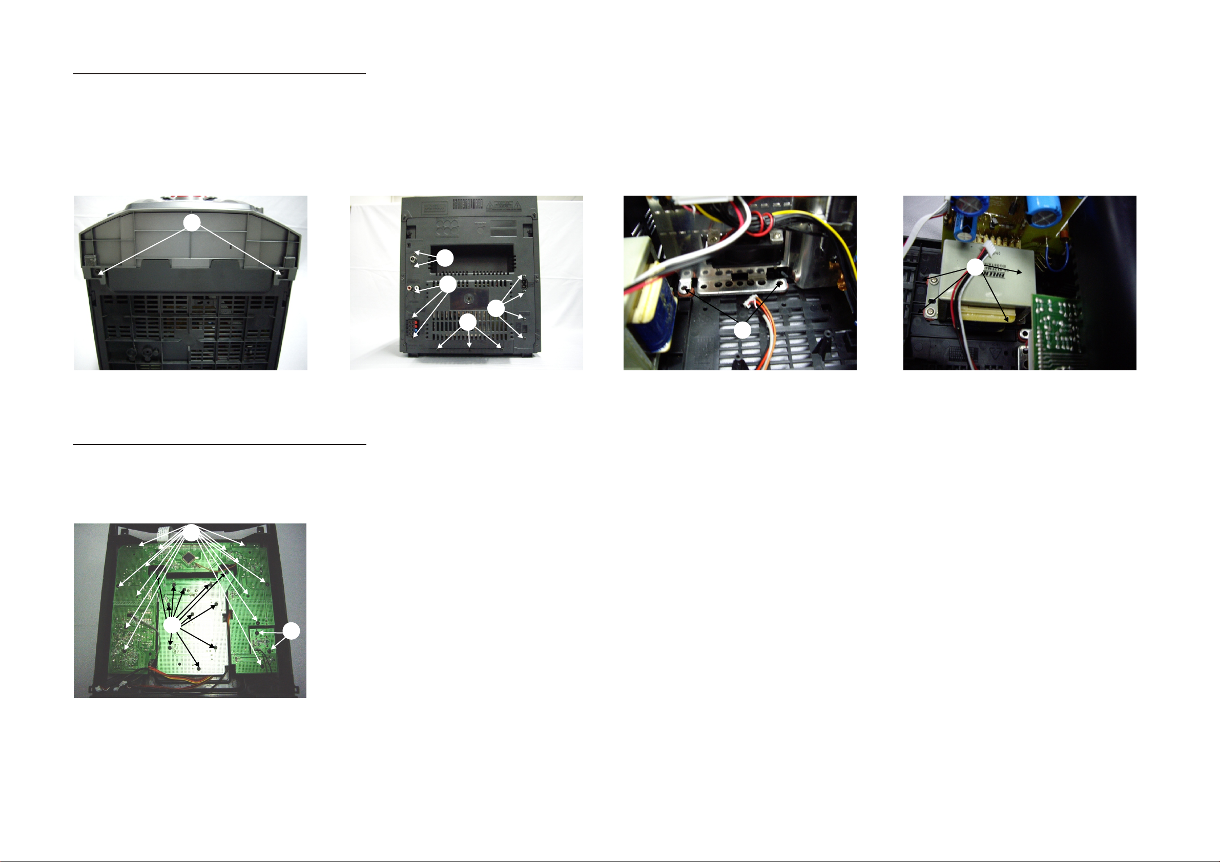
Dismantling of Rear portion
1) Remove 2 screws C a s indicated to loosen the Front Ca binet.
2) Remove 2 screws D a s indicated to loosen the Tuner Modu le.
3) Remove 9 screws E &I as indicated to lo osen the Main B oard.
4) Remove 8 screws G &H as indicated to lo osen the P OWE R Board.
5) Remove 3 screws F a s indicated to loosen the Bottom C abinet.
5-2
C
D
E
5-2
H
G
F
I
Dismantling of the PCB Board
1) Remove 14 screw s J as indicated to loo sen the DISPL AY1 Board.
2) Remove 11 screw s K as indicated to loo sen the KEY Boa rd.
3) Remove 2 screws L a s indicated to loos en the USB Jack B oard.
J
K
L
 Loading...