

Philips FWC MAS55 Service Manual

Mini System
FWC, MAS55
all versions
TABLE OF CONTENTS
Handling chip components ............................................................ 1-1
Leadfree and safety information ................................................... 1-2
Technical specification .................................................................. 2-1
Service tools .................................................................................. 2-1
Service measurement setup ......................................................... 2-2
Connections and controls ..................................................... 3-1...3-3
Disassembly diagram .................................................................... 4-1
Block diagram ............................................................................... 5-1
Wiring diagram .............................................................................. 5-2
Radio board
circuit diagram .......................................................................... 6-1
layout diagram .......................................................................... 6-2
Cassette board
circuit diagram .......................................................................... 7-1
layout diagram .......................................................................... 7-2
CD board
circuit diagram. ......................................................................... 8-1
layout diagram .......................................................................... 8-2
Control and Main board
circuit diagram (control board) ................................................. 9-1
circuit diagram (main board) .................................................... 9-2
layout diagram .......................................................................... 9-3
Exploded view diagram .................................................... 10-1 ...10-2
Mechanical partslist ..................................................................... 10-2
Electrical partslist .........................................................................11-1
©
Copyright 2005 Philips Consumer Electronics B.V. Eindhoven, The Netherlands
All rights reserved. No part of this publication may be reproduced, stored in a retrieval
system or transmitted, in any form or by any means, electronic, mechanical, photocopying,
or otherwise without the prior permission of Philips.
Published by YT 0521 Service Audio Printed in The Netherlands Subject to modification
Version 1.0
© 3141 785 30350
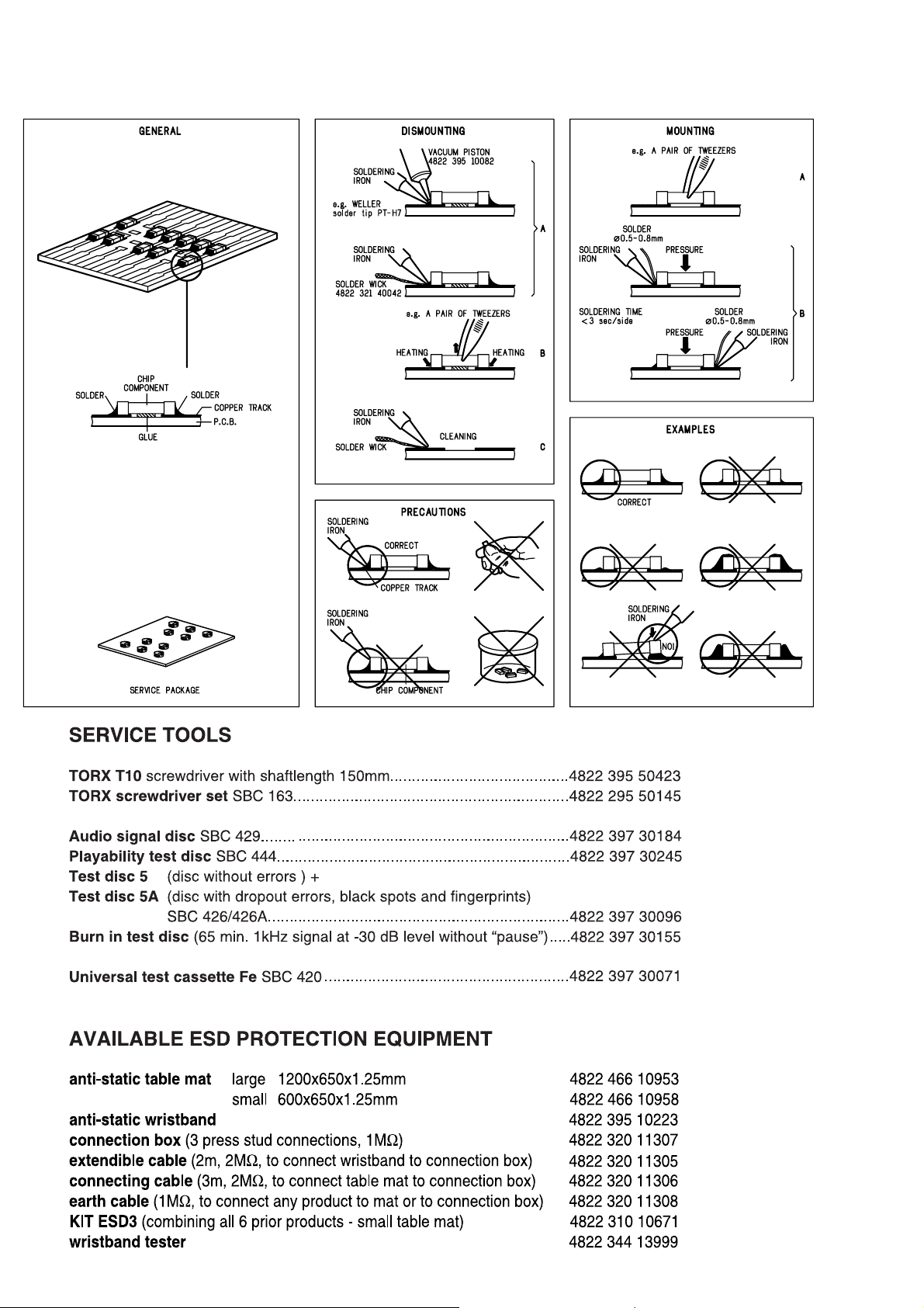
HANDLING CHIP COMPONENTS
1 - 1
1 - 2
2 - 1
SERVICE MEASUREMENT
2 - 2
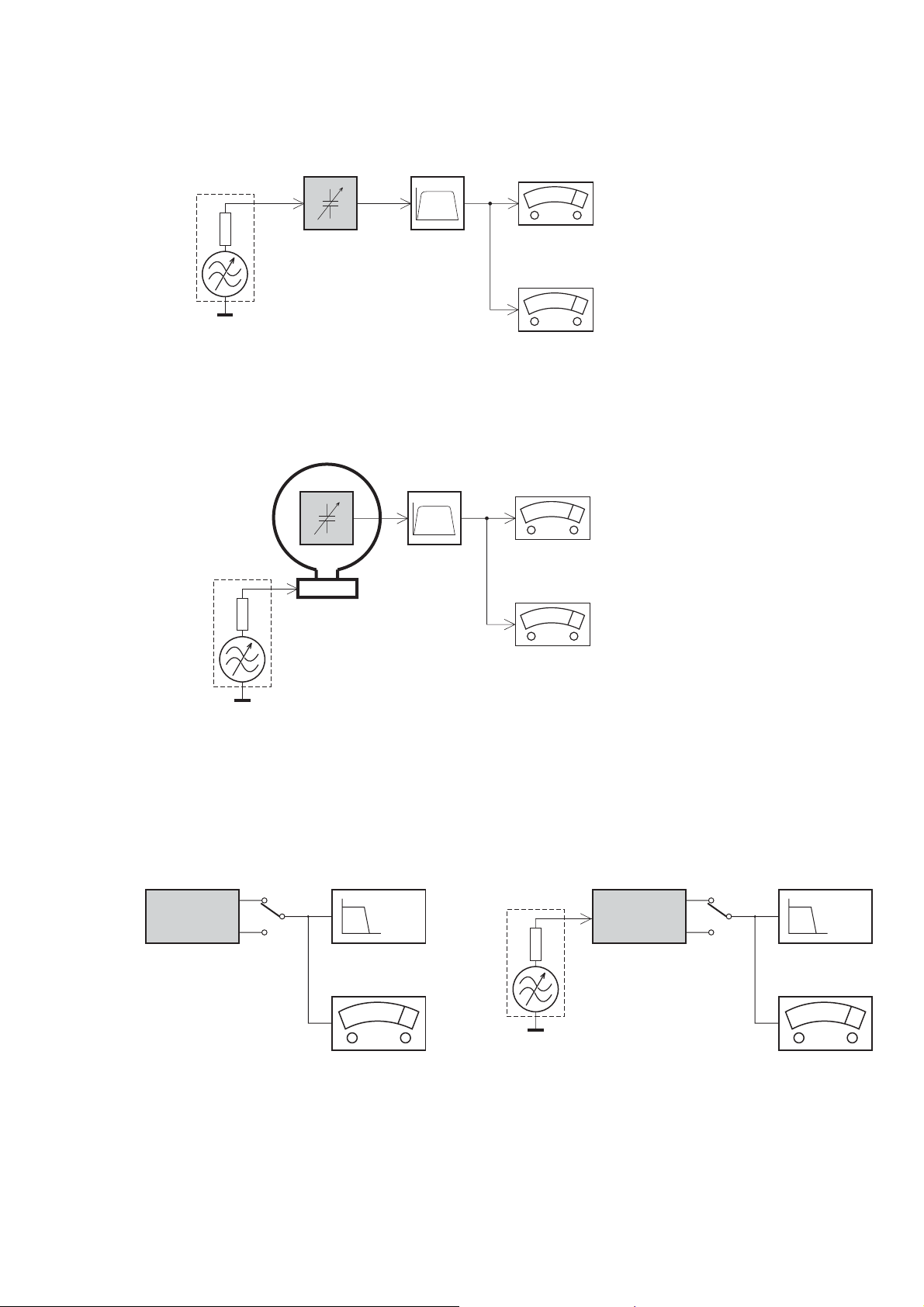
Tuner FW
RF Generator
e.g. PM5326
DUT
Bandpass
250Hz-15kHz
e.g. 7122 707 48001
LF Voltmeter
e.g. PM2534
½
Ri=50
S/N and distortion meter
e.g. Sound Technology ST1700B
Use a bandpass filter to eliminate hum (50Hz, 100Hz) and disturbance from the pilottone (19kHz, 38kHz).
Tuner AM (MW,LW)
RF Generator
e.g. PM5326
½
Ri=50
DUT
Frame aerial
e.g. 7122 707 89001
Bandpass
250Hz-15kHz
e.g. 7122 707 48001
LF Voltmeter
e.g. PM2534
S/N and distortion meter
e.g. Sound Technology ST1700B
To avoid atmospheric interference all AM-measurements have to be carried out in a Faraday«s cage.
Use a bandpass filter (or at least a high pass filter with 250kHz) to eliminate hum (50Hz, 100Hz).
CD RECORDER
Use Audio Signal Disc SBC429 4822 397 30184
(replaces test disc 3)
DUT
L
R
S/N and distortion meter
e.g. Sound Technology ST1700B
LEVEL METER
e.g. Sennheiser UPM550
with FF-filter
Use Universal Test Cassette Fe SBC420 4822 397 30071
LF Generator
e.g. PM5110
DUT
½
Ri=50
L
R
S/N and distortion meter
e.g. Sound Technology ST1700B
LEVEL METER
e.g. Sennheiser UPM550
with FF-filter

CONNECTION AND CONTROLS
3 - 1

CONNECTION AND CONTROLS
3 - 2
 Loading...