


EXP7361
all versions
© 3103 785 25240
Published by PW 0417 Service Audio Printed in The Netherlands Subject to modification
Version 1.0
Portable CD-player with MP3/WMA playback
TABLE OF CONTENTS
©
Copyright 2004 Philips Consumer Electronics B.V. Eindhoven, The Netherlands
All rights reserved. No part of this publication may be reproduced, stored in a retrieval
system or transmitted, in any form or by any means, electronic, mechanical, photocopying,
or otherwise without the prior permission of Philips.
Technical specification ......................................................1-1
Connections and controls..................................................1-2
Features ............................................................................1-3
Accessories .......................................................................1-3
Safety & Warnings.............................................................1-4
Service hints
Lead free soldering .......................................................2-1
Dismantling instructions ................................................2-1
Repair positions ............................................................2-2
Reassembling instructions ............................................2-2
Handling chip components............................................2-3
Service tools..................................................................2-3
Pin description of ICs.........................................................3-1
Service Test Program........................................................3-4
Blockdiagram.....................................................................3-6
Circuit diagrams
Supply part....................................................................4-1
Control part ...................................................................4-2
CD part..........................................................................4-3
Tuner part......................................................................4-4
Printed circuit board
Componentside view.....................................................4-5
Copperside view............................................................4-6
Exploded view ...................................................................5-1
Mechanical partslist...........................................................6-1
Electrical partslist...............................................................6-1
Revision list .......................................................................7-1
PRODUCT FAMILY EXPANIUM 7
CLASS 1
LASER PRODUCT

1-1
TECHNICAL SPECIFICATION
General
Dimensions (W x H x D) : 133 x 15.5 x 133mm
Weight without batteries : 150g
Power supply modes
DC-in socket (for play-mode) : 2.9..7.0V
DC-in socket (for charge-mode) : 3.6..7.0V
Primary batteries (battery box) : 1.7..3.2V
Rechargeable batteries (AY3365) : 1.7..3.2V
Voltage protection DC-in socket : -14.5..+14.5V
Battery lifetime
Battery level detection
Charge section (not on all versions)
Charge current : 250mA ±10%
Charge time for 80% AY3365 : 4.0h nom.
Charge time for 100% AY3365 : 6.0h nom.
Max. charge time (µP controlled) : 7h
Temperature protection : 50°C ±5°C
Current consumption
1)
off-phase means servos switched off and audio data is played back from
ESP memory
Headphone out CD/MP3/WMA (16Ω load, DBB/ESP=off)
Output power (THD≤10%)
/17 version only : 2x5mW (+2/-3dB)
all other versions : 2x2.5mW (+1/-3dB)
Frequency response (1mW) : 100Hz-20kHz within 6dB
S/N ratio (unwght) : ≥80dB (83dB typ.)
S/N ratio (A-wght) : ≥82dB (85dB typ.)
THD+N (1kHz, 1mW) : ≤1% (0.2% typ.)
Channel crosstalk (1kHz, no load): ≤-24dB (-30dB typ.)
Channel unbalance (-40dB) : ≤5dB
Volume attenuation (1kHz) : ≥60dB
Sound presets
Laser
Output power : <5mW (3mW typ.)
Wavelength : 780nm
Measurement setup CD/MP3/WMA
Use Audio Signal disc SBC429 4822 397 30184
FM-Tuner
Tuning range : 87.5..108MHz
Tuning grid : 50kHz (100kHz for /17)
IF : 225kHz
Sensitivity (26dB S/N, m=30%) : ≤22dBf (15dBf typ.)
-3dB limiting point : ≤26dBf (15dBf typ.)
Distortion (rf=1mV, ∆f=75kHz) : ≤7% (2% typ.)
Headphone out Tuner (16Ω load, DBB/ESP=off)
Output power (THD≤10%)
/17 version only : 2x5mW (+2/-3dB)
all other versions : 2x3mW (+1/-3dB)
Frequency response : 100Hz-9kHz within 6dB
S/N ratio stereo (A-wght) : ≥52dB (55dB typ.)
THD+N (1kHz, 0dB) : ≤1% (0.4% typ.)
Channel crosstalk (1kHz, no load): ≤-22dB (-25dB typ.)
Channel unbalance (1kHz, 0dB) : ≤5dB
Low pass filterDUT S/N and distortion meter
L
R
i.e. Sennheiser UPM550
with FF-filter
Level meter
i.e. Sound Technology ST1700Bi.e. 4822 395 30204
22kHz
13th order
TESERPDNUOS
esnopserycneuqerF
zHk36 zHk1 zHk01
1BBDBd6+ ± Bd2Bd0 ± Bd2Bd0 ± Bd2
2BBDBd21+ ± Bd2Bd0 ± Bd2Bd5+ ± Bd2
TNERRUC
NOITPMUSNOC
)V5.4(NI-CD )V52.2(YLPPUS.TTAB
PSE/MSP
ffo
MSP
esahp-no
MSP
esahp-ffo
MSP
egaregva
edom-yalP.pytAm98.pytAm021.pytAm04.pytAm38
edom-pmuJ.pytAm003.pytAm052
edom-egrahC.pytAm082a/n
edom-renuT.pytAm05.pytAm73
yb-dnatS
)egrahcer.lcxe(
.pytAm12.pytAm54.0
LEVELNOITCETED
yramirP
seirettab
elbaegrahceR
seirettab
ytpmeyrettaB
V7.1
± Vm001
V7.1
± Vm001
1kaewyrettaB
+levelytpmeyrettab
V9.0 ± Vm001
+levelytpmeyrettab
V7.0 ± Vm001
2kaewyrettaB
+levelytpmeyrettab
V6.0 ± Vm001
+levelytpmeyrettab
V5.0 ± Vm001
3kaewyrettaB
+levelytpmeyrettab
V3.0 ± Vm001
+levelytpmeyrettab
V3.0 ± Vm001
EMITEFILYRETTAB ADDC AMW/3PM
seirettabyramirP
60RLx2
≥ h32
).pyth54(
≥ h93
).pyth86(
seirettabelbaegrahceR
)hAm0021(5633YA
≥ h01
).pyth02(
≥ h61
).pyth82(

CONNECTIONS AND CONTROLS
Portable CD-player EXP7361 Remote Control AY3786
1-2
1 4.5V DC jack for AC/DC adaptor power supply
2 EXT. BATT jack for external battery supply
3 LOCK•UNLOCK locks/unlocks all buttons on the set only
4 p / LINE OUT connect the remote control here and your
headphones to the remote control
5 2; switches the player on, starts or pauses
CD play; stops CD play, clears a program or
switches the player off. Press and hold 2; for
2 seconds to enter stop mode.
6 switches radio on/off.
7 ∞ / § skips and searches backward / forward
tracks; (FM) tunes to stations
8 • • / • • opens the CD lid
9 VOL +/– adjusts the volume
0 Rechargeable battery compartment inside the CD player
The model & serial numbers are located inside the battery
compartment.
1 p 3.5mm headphone jack
2 Clip
3 LOCK•OFF locks/unlocks all buttons on the remote control
4 ∞ / § skips and searches backward / forward tracks;
(FM) tunes to stations
2; switches the player on, starts or pauses CD
play; stops CD play, clears a program or
switches the player off. Press and hold 2; for
2 seconds to enter stop mode.
ALBUM +/– MP3/WMA-CD only:
• selects the previous or next album
• skips backward or forward
5 VOL +/– adjusts the volume
6 DBB switches the bass enhancement on/off
7 PROG programs tracks
programs FM station presets
8 MODE selects playback options;
to select and enter the display function, press
and hold MODE for 3 seconds.
9 Display
0 FM switches radio on/off

FEATURES
ACCESSORIES
ELBATROP-DCROFSEIROSSECCA
”7MUINAPXE“YLIMAFTCUDORP
1637PXE
c00/ 10/ z50/ 01/ 51/ 71/
00/0713YA rotpadACD/CA716019122284X
20/0713YA rotpadACD/CA676019122284X
50/0713YA rotpadACD/CA016338110413X
01/0713YA rotpadACD/CA281238110413X
51/B001WJ rotpadACD/CA168338110413X
71/0713YA rotpadACD/CA616019122284X
8623YA hcuoPgniyrraC118013110413 XXXXXX
5633YA seirettaBelbaegrahceR128488033013 XXXXXX
0833YA esaCyrettaBlanretxE162158110413 XXXXXX
4643YA mm5.3(DROCIFIH → )gulp-L,hcnic188110232284 OOOOOO
00/1053YA ettessaCrotpadAraC950017932284 OOOOOO
00/5453YA retrevnoCCD/CDraC330019122284 OOOOOO
6873YA lortnoCetomeRDCLdroC192558033013 XXXXXX
s77/075EHCBS )gulp-S(enohpraE427100012809 XXXXXX
elbaliavalanoitpo...O,tesehthtiwdeilppus...X
ELBATROP-DCFOSERUTAEF
”7MUINAPXE“YLIMAFTCUDORP
1637PXE
snoisrevlla
KCABYALPAMW/3PM/CAA/– ● / ●
YTILIBITAPMOCELBATIRWER-DC
●
ADDCNOITCETORPPIKSCINORTCELEs371
3PMNOITCETORPPIKSCINORTCELEs574
EZISMARDPSEtibM46
EDOMEVASREWOP
●
NOITCNUFEMUSER/DLOH
● / ●
SEGATSELBERT/BBD2
KCABDEEFCITSUOCA
●
YROMEMMARGORP99
NOITCNUFEGRAHCER
●
PILCTLEB–
LORTNOCETOMERDCLDROC
●
THGILKCABYALPSID–
TUPTUOLATIGID/ENIL–/–
1-3

SAFETY & WARNINGS
© WARNING
All ICs and many other semiconductors are susceptible to
electrostatic discharges (ESD). Careless handling during
repair can reduce life drastically.
When repairing, make sure that you are connected with the
same potential as the mass of the set via a wristband with
resistance. Keep components and tools at this potential.
f ATTENTION
Tous les IC et beaucoup d´autres semi-conducteurs sont
sensibles aux décharges statiques (ESD). Leur longévite
pourrait être considérablement écourtée par le fait qu´aucune
précaution nést prise à leur manipulation.
Lors de réparations, s´assurer de bien être relié au même
potentiel que la masse de l´appareil et enfileer le bracelet
serti d´une résistance de sécurité.
Veiller à ce que les composants ainsi que les outils que l´on
utilise soient également à ce potentiel.
d WARNUNG
Alle ICs und viele andere Halbleiter sind empfindlich
gegenüber elektrostatischen Entladungen (ESD).
Unsorgfältige Behandlung im Reparaturfall kann die
Lebensdauer drastisch reduzieren.
Sorgen Sie dafür, daß Sie im Reparaturfall über ein Pulsarmband mit Widerstand mit dem Massepotential des
Gerätes verbunden sind.
Halten Sie Bauteile und Hilfsmittel ebenfalls auf diesem
Potential.
ñ WAARSCHUWING
Alle IC´s en vele andere halfgeleiders zijn gevoelig voor
electrostatische ontladingen (ESD).
Onzorgvuldig behandelen tijdens reparatie kan de levensduur
drastisch doen vermindern. Zorg ervoor dat u tijdens reparatie
via een polsband met weerstand verbonden bent met hetzelfde
potentiaal als de massa van het apparaat.
Houd componenten en hulpmiddelen ook op ditzelfde potentiaal.
i AVVERTIMENTO
Tutti IC e parecchi semi-conduttori sono sensibili alle scariche
statiche (ESD).
La loro longevità potrebbe essere fortemente ridatta in caso di
non osservazione della più grande cauzione alla loro
manipolazione. Durante le riparationi occorre quindi essere
collegato allo stesso potenziale che quello della massa
delápparecchio tramite un braccialetto a resistenza.
Assicurarsi che i componenti e anche gli utensili con quali si
lavora siano anche a questo potenziale.
©
Safety regulations require that the set be restored to its
original condition and that parts which are identical with
those specified be used.
Safety components are marked by the symbol
i
Le norme di sicurezza estigono che l´apparecchio venga
rimesso nelle condizioni originali e che siano utilizzati i
pezzi di ricambiago identici a quelli specificati.
Componenty di sicurezza sono marcati con
ñ
Veiligheidsbepalingen vereisen, dat het apparaat in zijn
oorspronkeliijke toestand wordt teruggebracht en dat
onderdelen, identiek aan de gespecificeerde, worden toegepast.
De Veiligheidsonderdelen zijn aangeduid met het symbool
s Varning !
Osynlig laserstrålning när apparaten är öppnad och
spärren är urkopplad. Betrakta ej strålen.
∂ Advarsel !
Usynlig laserstråling ved åbning når sikkerhedsafbrydere
er ude af funktion. Undgå udsaettelse for stråling.
ß Varoitus !
Avatussa laitteessa ja suojalukituksen ohitettaessa olet alttiina
näkymättömälle laserisäteilylle. Älä katso säteeseen !
ESD
SAFETY
d
Bei jeder Reparatur sind die geltenden Sicherheitsvorschriften zu beachten. Der Originalzustand des Gerätes
darf nicht verändert werden. Für Reparaturen sind Originalersatzteile zu verwenden.
Sicherheitsbauteile sind durch das Symbol markiert.
f
Les normes de sécurité exigent que l`appareil soit remis
à l`état d`origine et que soient utilisées les pièces de
rechange identiques à celles spécifiées.
Les composants de sécurité sont marqués
CLASS 1
LASER PRODUCT
©
DANGER: Invisible laser radiation when open.
AVOID DIRECT EXPOSURE TO BEAM.
1-4
SERVICE HINTS
LEAD FREE PRODUCED SET
This set is manufactured with lead-free
production technology. This is also indicated by
the PHILIPS-lead-free logo you find on the
printed boards.
The set is produced with lead-free solder-alloy as well as
with lead-free sub-parts. It can be considered as lead-free.
Due to this fact some rules have to be respected by the
workshop during a repair:
• Use only lead-free soldering-tin Philips SAC305 with order
code 0622 149 00106. If lead-free solder-paste is required,
please contact the manufacturer of your solder-equipment.
• Use only adequate solder tools applicable for lead-free
soldering-tin.
• Adjust your solder tool so that a temperature around 217°
– 220° is reached at the solder joint.
• Do not mix lead-free soldering-tin with leaded soldering-tin.
This would lead to unreliable solder joints.
• On our website http://www.atyourservice.ce.philips.com
you find more information to
– aspects of lead-free technology
– BGA-de-/soldering, heating-profiles of BGAs used in
Philips-sets, and others
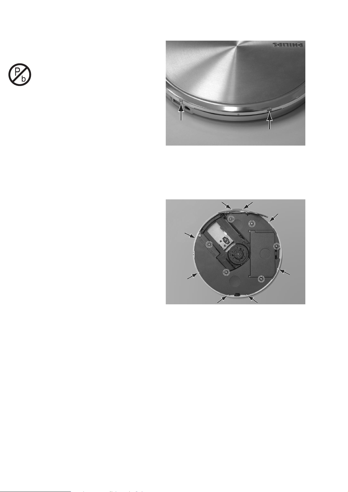
DISMANTLING CD-DOOR
To dismantle the CD-door proceed as follows:
1. Loosen screws on back side of player (2x)
2. Open CD-door
3. Lift CD-door
DISMANTLING CABINET
To dismantle the cabinet proceed as follows:
1. Dismantle CD-door
2. Loosen screws of cabinet (6x)
3. Release snaps from bottom to cabinet (8x)
4. Lift cabinet
2-1

REPAIR POSITION TOP-SIDE
To get access to the top-side of the Main Board proceed
as follows:
1. Dismantle CD-door
2. Dismantle cabinet
3. Supply the unit via external DC-socket
4. To carry out measurements short-circuit door-switch or
start Service Test Program → Playback Test
REPAIR POSITION BOTTOM-SIDE
To get access to the botom-side of the Main Board
proceed as follows:
1. Dismantle CD-door
2. Dismantle cabinet
3. Lift printed boards and place flipped boards into cabinet
4. Position cabinet over bottom so that CD can turn without
touching other parts
5. Supply the unit via external DC-socket
6. To carry out measurements short-circuit door-switch or
start Service Test Program → Playback Test
REASSEMBLING THE UNIT
When reassembling the unit take care that
• the door-switch is operable
• lock switch & lock slider are in the correct position
• the battery spring contacts are not hidden behind studs
• the opening mechanism is locked
When mounting cabinet to bottom start locking snaps
around the opening mechanism first.
2-2

HANDLING CHIP COMPONENTS
SERVICE TOOLS
Audio signal disc SBC429 4822 397 30184
Playability test disc SBC444A 4822 397 30245
CD-RW printed audio disc 7104 099 96611
MP3 8cm disc (for testing MP3 files, bitrates: 128; 160 and 192 kbit/s) 7104 099 28271
SubChassis 8A test disc (8cm disc) 7104 099 32841
ESD PROTECTION EQUIPMENT
ESD3 KIT 4822 310 10671
• Anti-static table mat (600x650x1.25mm)
• Anti-static wristband
• Connection box (3 press stud connections, 1MΩ)
• Extendible cable (2m, 2MΩ, to connect wristband to connection box)
• Connecting cable (3m, 2MΩ, to connect table mat to connection box)
• Earch cable (1MΩ, to connect any product to table mat or to connection box)
2-3

PIN DESCRIPTION OF INTEGRATED CIRCUITS
TEA5767HN – LOW POWER FM-TUNER
Pin Name Direction Description
1 NC1 – no connection
2 CPOUT FM-tuner → charge pump output of synthesizer PLL
3 VCOTANK1 FM-tuner → voltage controlled oscillator tuned circuit output 1
4 VCOTANK2 FM-tuner → voltage controlled oscillator tuned circuit output 2
5 VCCVCO →FM-tuner voltage controlled oscillator supply voltage
6 DGND GND digital ground
7 VDIG → FM-tuner digital supply voltage
8 DATA µP ↔ FM-tuner bus data line input/output
9 CLOCK µP → FM-tuner bus clock line input
10 NC2 – no connection
11 WRITE/READ µP → FM-tuner write/read control input for the 3-wire bus
12 BUSMODE → FM-tuner bus mode select input
13 BUSENABLE → FM-tuner bus enable input
14 SWPORT1 → FM-tuner software programmable port 1
15 SWPORT2 → FM-tuner software programmable port 2
16 XTAL1 → FM-tuner crystal oscillator input 1
17 XTAL2 → FM-tuner crystal oscillator input 2
18 PHASEDET → FM-tuner phase detector loop filter
19 PILDET → FM-tuner pilot detector low-pass filter
20 NC3 – no connection
21 NC4 – no connection
22 VAFL FM-tuner → headphone amp. left audio frequency output voltage
23 VAFR FM-tuner → headphone amp. right audio frequency output voltage
24 TMUTE → FM-tuner time constant for soft mute
25 MPXOUT FM-tuner → FM demodulator MPX signal output
26 VREF → FM-tuner reference voltage
27 TIFCENTER → FM-tuner time constant for IF centre adjust
28 LIMDEC1 → FM-tuner decoupling IF limiter 1
29 LIMDEC2 → FM-tuner decoupling IF limiter 2
30 NC5 – no connection
31 NC6 – no connection
32 IGAIN → FM-tuner gain control current for IF filter
33 AGND GND analog ground
34 VCC → FM-tuner analog supply voltage
35 RFIN1 → FM-tuner RF input 1
36 RFGND GND RF ground
37 RFIN2 → FM-tuner RF input 2
38 CAGC → FM-tuner time constant RF AGC
39 LOOPSW FM-tuner → switch output of synthesizer PLL loop filter
40 NC7 – no connection
AN8399SA – HF-PREAMPLIFIER
Pin Name Direction Description
1PD → HF-preamp input for LD output monitoring PD signals
2LD → HF-preamp external TR drive pin for driving LD
3 VCC +HF (+2.6V) power supply
4 RFN → HF-preamp RF addition amp inverting input
5 RFOUT HF-preamp → RF addition amp output
6 RFIN → HF-preamp AGC amp input
7 LDRCTL → HF-preamp LD reference voltage control pin
8 CAGC → HF-preamp AGC loop filter connection pin
9 ARF HF-preamp → RF after AGC output
10 CEA → HF-preamp capacitor for 3T-ENV detection filter connection pin
11 3TOUT HF-preamp → 3T-ENV detection output
12 CBDO → HF-preamp capacitor for low-speed dark level BDO detection connection pin
13 BDO HF-preamp → BDO detection output
14 COFTR → HF-preamp capacitor for low-speed off-track detection connection pin
15 OFTR HF-preamp → off-track detection output
16 NRFDET HF-preamp → RF signal amplitude detection information output
17 GND GND ground pin
18 SLPSW → HF-preamp sleep mode control pin
19 VREF VREF reference voltage output (VCC / 2)
20 TEN → HF-preamp TE amp inverting input
21 TEOUT HF-preamp → track error output
22 FEN → HF-preamp FE amp inverting input
23 FEOUT HF-preamp → focus error output
24 GCTL → HF-preamp gain & APC control pin
25 FBAL → HF-preamp pin to input signal for controlling focus balance adjustment
26 TBAL → HF-preamp pin to input signal for controlling tracking balance adjustment
27 E → HF-preamp satellite diode signal input
28 F → HF-preamp satellite diode signal input
29 D → HF-preamp central diode signal input
30 B → HF-preamp central diode signal input
31 C → HF-preamp central diode signal input
32 A → HF-preamp central diode signal input
3-1

SM8613AV – LASER DIODE DRIVER
Pin Name Direction Description
1 LDISET → laser diode driver LD drive maximum current setting resistor connection
2 NC1 – no connection
3 MUTE → laser diode driver intermittent drive stop signal
4PCK →laser diode driver intermittent control reference pulse input
5 DUTYADJ → laser diode driver intermittent duty ratio adjust resistor connection
6 FLOCK → laser diode driver intermittent drive control signal
7 NC2 – no connection
8 GND GND ground
9 PDVIN → laser diode driver laser luminosity monitor voltage input
10 NC3 – no connection
11 LDOFF → laser diode driver LD drive current control signal
12 LDIOUT laser diode driver → LD drive current output
13 VCC +2.6V supply voltage
14 RG2 laser diode driver → APC frequency response control capacitor connection
15 NC4 – no connection
16 RG1 → laser diode driver APC loop gain control resistor connection
LV8222W – PWM-DRIVER
Pin Name Direction Description
1RF → PWM-driver output current detection pin
2 COM PWM-driver → common point of spindle motor
3VS → PWM-driver power supply for spindle motor driver
4 CP1 PWM-driver → charge pump pulse output pin
5 CPC1 → PWM-driver pin for charge pump
6 CP2 PWM-driver → charge pump pulse output pin
7 CPC2 → PWM-driver pin for charge pump
8VG → PWM-driver pin for charge pump
9 VCC +2.6V power supply for the small signal system circuit
10 FG PWM-driver → µP FG pulse output
11 FIL → PWM-driver waveform synthetic signal filter pin
12 COMIN → PWM-driver differential input of position detection comparator
13 S_S µP → PWM-driver start/stop input of spindle motor block
14 PWM → PWM-driver PWM signal input of spindle motor block
15 BRK → PWM-driver brake input of spindle motor block
16 MODE1 → PWM-driver PWM frequency switching pin of spindle motor block
17 MODE2 → PWM-driver soft switching characteristic select pin of spindle motor block
18 NC – no connection
19 RMAX → PWM-driver sets maximum frequency of VCO pin
20 VCOIN → PWM-driver pin to control voltage of VCO pin
21 VCO → PWM-driver oscillation frequency of VCO pin
22 VGREG → PWM-driver pre-drive regulator pin
23 VSMON PWM-driver → µP power supply voltage monitor pin
24 TGND GND ground of small signal system
25 GND GND ground of small signal system
26 CLK µP → PWM-driver channel 3 reverse output
27 IN3R → PWM-driver logic input pin of actuator H-bridge 3
28 IN3F → PWM-driver logic input pin of actuator H-bridge 3
29 IN2R → PWM-driver logic input pin of actuator H-bridge 2
30 IN2F → PWM-driver logic input pin of actuator H-bridge 2
31 IN1R → PWM-driver logic input pin of actuator H-bridge 1
32 IN1F → PWM-driver logic input pin of actuator H-bridge 1
33 VS3 +A power supply for H-bridge 3
34 MUTE µP → PWM-driver H-bridge and three-phase sled mute pin
35 OUT3R PWM-driver → H-bridge forward/reverse output 3
36 PGND3 GND ground of H-bridge output block 3
37 OUT3F PWM-driver → H-bridge forward/reverse output 3
38 OUT2R PWM-driver → H-bridge forward/reverse output 2
39 VS2 +A power supply for H-bridge 2
40 PGND2 GND ground of H-bridge output block 2
41 OUT2F PWM-driver → H-bridge forward/reverse output 2
42 OUT1R PWM-driver → H-bridge forward/reverse output 1
43 PGND1 GND ground of H-bridge output block 1
44 VS1 +A power supply for H-bridge 1
45 OUT1F servo driver → H-bridge forward/reverse output 1
46 WOUT PWM-driver → output pin for spindle motor
47 VOUT PWM-driver → output pin for spindle motor
48 UOUT PWM-driver → output pin for spindle motor
3-2

MN662793CF – DIGITAL SIGNAL PROCESSOR FOR CD
Pin Name Direction Description
1 D11 signal processor ↔ DRAM DRAM data I/O signal 11
2 D10 signal processor ↔ DRAM DRAM data I/O signal 10
3 D9 signal processor ↔ DRAM DRAM data I/O signal 9
4 D8 signal processor ↔ DRAM DRAM data I/O signal 8
5 UDQM signal processor → DRAM SDRAM upper byte data mask signal output
6 SDRCK signal processor → DRAM SDRAM clock signal output
7 A11 signal processor → DRAM DRAM address signal 11
8 A9 signal processor → DRAM DRAM address signal 9
9 A8 signal processor → DRAM DRAM address signal 8
10 A7 signal processor → DRAM DRAM address signal 7
11 A6 signal processor → DRAM DRAM address signal 6
12 A5 signal processor → DRAM DRAM address signal 5
13 A4 signal processor → DRAM DRAM address signal 4
14 LDQM signal processor → DRAM SDRAM lower byte data mask signal output
15 NWE signal processor → DRAM DRAM write enable signal output
16 NCAS signal processor → DRAM DRAM CAS control signal output
17 NRAS signal processor → DRAM DRAM RAS control signal output
18 NCS signal processor → DRAM SDRAM chip select signal output
19 A3 signal processor → DRAM DRAM address signal 3
20 A2 signal processor → DRAM DRAM address signal 2
21 A1 signal processor → DRAM DRAM address signal 1
22 A0 signal processor → DRAM DRAM address signal 0
23 DRVDD1 +RAM power supply 1 for DRAM interface I/O
24 DVSS1 GND ground 1 for digital circuits
25 A10 signal processor → DRAM DRAM address signal 10
26 BA1 signal processor → DRAM SDRAM bank selection signal output 1
27 BA0 signal processor → DRAM SDRAM bank selection signal output 0
28 DVDD1 +1.8V power supply 1 for internal digital circuits
29 SPOUT signal processor → PWM-driver spindle drive signal output (absolute value)
30 SPPOL signal processor → PWM-driver spindle drive signal output (polarity)
31 TRVP signal processor → PWM-driver traverse drive signal output (positive polarity)
32 TRVM signal processor → PWM-driver traverse drive signal output (negative polarity)
33 TRVP2 signal processor → traverse drive signal output 2 (positive polarity)
34 TRVM2 signal processor → traverse drive signal output 2 (negative polarity)
35 TRP signal processor → PWM-driver tracking drive signal output (positive polarity)
36 TRM signal processor → PWM-driver tracking drive signal output (negative polarity)
37 FOP signal processor → PWM-driver focus drive signal output positive polarity)
38 FOM signal processor → PWM-driver focus drive signal output (negative polarity)
39 IOVDD1 +DSP power supply 1 for digital I/O
40 TBAL signal processor → HF-preamp tracking balance adjustment signal output
41 FBAL signal processor → HF-preamp focus balance adjustment signal output
42 FE HF-preamp → signal processor focus error signal input
43 TE HF-preamp → signal processor tracking error signal input
44 ADPVCC PWM-driver → signal processor voltage input for supply voltage monitor
45 RFENV HF-preamp → signal processor RF envelope signal input
46 LDON signal processor → laser on signal output
47 NRFDET HF-preamp → signal processor RF detection signal input
48 OFT HF-preamp → signal processor off-track signal input
49 BDO HF-preamp → signal processor dropout signal input
50 AVDD1 +HF (+2.6V) power supply 1 for analog circuits
51 IREF → signal processor analog reference current input
52 ARF HF-preamp → signal processor RF signal input
53 DSLF → signal processor DSL loop filter pin
54 PWMSEL → signal processor PWM output mode selection input (low=direct, high=3-state)
55 PLLF signal processor → PLL loop filter pin (for phase comparison)
56 PLLFO signal processor → PLL loop filter pin (for speed comparison)
57 AVSS1 GND ground 1 for analog circuits
58 LOOUTL signal processor → headphone amp. left channel audio output for line-out output
59 LOVSS1 GND ground 1 for line-out output
60 LOOUTR signal processor → headphone amp. right channel audio output for line-out output
61 LOVDD1 +3.0V power supply 1 for line-out output
62 NTEST2 → signal processor headphone output control input
63 TMON1 signal processor → left channel audio output for headphone output
64 LOVDD2 +3.0V power supply 2 for headphone output
65 LOVSS2 GND ground 2 for headphone output
66 TMON2 signal processor → right channel audio output for headphone output
67 DVDD3 +1.8V power supply 3 for digital circuits
68 DVSS2 GND ground 2 for digital circuits
69 EXT0 signal processor ↔ expansion I/O port 0
70 EXT1 signal processor ↔ expansion I/O port 1
71 EXT2 signal processor ↔ expansion I/O port 2
72 MCLK µP → signal processor microcontroller command clock signal input
73 MDATA µP → signal processor microcontroller command data signal input
74 MLD µP → signal processor microcontroller command load signal input
75 STAT signal processor → µP status signal output
76 BLKCK signal processor → µP subcode block clock signal output
77 SMCK signal processor → PWM-driver 4.2336MHz/8.4672MHz clock signal output
78 PMCK signal processor → 88.2kHz clock signal output
79 TX signal processor → digital audio interface signal output
80 FLAG signal processor → flag signal output
81 NRST µP → signal processor LSI reset signal input
82 NTEST +DSP test mode setting input
83 DVSS3 GND ground 3 for digital circuits
84 X1 → signal processor crystal oscillator circuit input
85 X2 signal processor → crystal oscillator circuit output
86 IOVDD2 +DSP power supply 2 for digital I/O
87 DVDD2 +1.8V power supply 2 for internal digital circuits
88 D2 signal processor ↔ DRAM DRAM data I/O signal 2
89 D1 signal processor ↔ DRAM DRAM data I/O signal 1
90 D0 signal processor ↔ DRAM DRAM data I/O signal 0
91 D3 signal processor ↔ DRAM DRAM data I/O signal 3
92 D4 signal processor ↔ DRAM DRAM data I/O signal 4
93 D5 signal processor ↔ DRAM DRAM data I/O signal 5
94 D6 signal processor ↔ DRAM DRAM data I/O signal 6
95 D7 signal processor ↔ DRAM DRAM data I/O signal 7
96 D15 signal processor ↔ DRAM DRAM data I/O signal 15
97 D14 signal processor ↔ DRAM DRAM data I/O signal 14
98 DRVDD2 +RAM power supply 2 for DRAM interface I/O
99 D13 signal processor ↔ DRAM DRAM data I/O signal 13
100 D12 signal processor ↔ DRAM DRAM data I/O signal 12
3-3

SERVICE TEST PROGRAM
To enter the Service Test Program proceed as follows:
1. Disconnect the AC/DC adaptor and remove batteries
2. Open the CD-door
3. Hold PLAY & NEXT buttons depressed
4. Connect the AC/DC adaptor or insert batteries
The display shows the software version (e.g. “S-1201”).
The program is now in the main menu. The built-in tests
can be started via dedicated buttons. See flow chart on
next page for details.
table1 – error codes for playback test
EDOC RORRE EPYT ESUAC
0001rorresucoflatafnon.kcabyalpgnirudtsolsisucofehtnehwdereggirT
1001rorrelaidarlatafnon .kcabyalpgnirudemitniatrecarofkcart-ffosiovreslaidarehtnehwdereggirT
2001rorreniedilslatafnon
6yletamixorppaerofeb)desolcsihctiwsrenni(noitisoprennistihcaertondidedilsehT
.melborprotomedilsrohctiwsrenni–ybdessapevahsdnoces
3001rorretuoedilslatafnon
yletamixorppaerofeb)neposihctiwsrenni(noitisoprennistifotuoemoctondidedilsehT
.melborprotomedilsrohctiwsrenni–ybdessapevahsm052
4001rorregnillifMARDlatafnon
,eroferehT.semarfoiduaevitucesnocowttcennocotelbatonsawrellortnocMARDehT
eht µ .skcilcelbiduasecudorptahtnoitcennocoiduatceridaeussiotdahP
5001rorrepmujlatafnon .emitniatrecanihtiwdnuofebtondluocnoitanitsedpmujehtnehwdereggirT
6001rorreedocbuslatafnon.yalpgnirudemitniatrecarofedocbusdilavoN
7001rorreLLPlatafnon.emitniatrecanihtiwkcoltondluocpooL-kcoL-esahPehT
8001rorrerotomelbatnrutlatafnonnihtiwtonsideepsrotomnehwdetareneG ± .deepstegratfo%02
9001rorreoidualatafnon.rorreoiduaelbatcerrocnU
0101
tnemtsujdacitamotua
rorre
latafnon .emitniatrecanihtiwlufsseccustonsawtnemtsujdaniagcitamotuA
1101rorreniaghguorsucoflatafnon .emitniatrecanihtiwlufsseccustonsawtnemtsujdaniaghguorsucoF
0201rorrehcraessucoflataf.emitniatrecanihtiwdnuofneebtonsahtniopsucofehT
2201rorreedocbuslataflataf.noitamrofniedocbusdilaveromoN
0301
tnemtsujdacitamotua
rorreniaghguorsucof
lataf .emitniatrecanihtiwlufsseccustonsawniaghguorsucofCGAehT
4301
4401
tnemtsujdacitamotua
rorreniaghguorgnikcart
lataf .emitniatrecanihtiwlufsseccustonsawniaghguorgnikcartCGAehT
5301
5401
tnemtsujdacitamotua
rorreecnalabkcart
lataf .emitniatrecanihtiwlufsseccustonsawecnalabkcartsucofCGAehT
6301
6401
tnemtsujdacitamotua
rorreecnalabsucof
lataf .emitniatrecanihtiwlufsseccustonsawecnalabsucofCGAehT
7301
7401
tnemtsujdacitamotua
rorreniagenifsucof
lataf .emitniatrecanihtiwlufsseccustonsawniagenifsucofCGAehT
8301
8401
tnemtsujdacitamotua
rorreniagenifgnikcart
lataf .emitniatrecanihtiwlufsseccustonsawniagenifgnikcartCGAehT
3-4

3-53-5
SERVICE TEST PROGRAM – FLOW CHART
“VOL-”
pressed?
Y
PLA YBACK TEST
Close CD-door &
press “PLA Y”
Error during
playback?
Y
Display shows
error-code
(see table1)
Fatal error?
Y
Stop playback
EXIT
SERVICE TEST
PROGRAM
N
N
N
“NEXT”
pressed?
Y
KEY TEST
Display shows
“Key --”
key held
depressed?
Y
Display shows
keycode
(see table2)
EXIT
SERVICE TEST
PROGRAM
N
N
“FM”
pressed?
Y
TUNER TEST
Display shows
“FM USA” or
“FM EUROPE”
“FM”
pressed?
Y
Tuner functional
test with presets
(see table3)
N
N
(FM grid=100kHz)
“NEXT”
depressed?
Y
“C USA”
Set version USA
N
depressed?
“C EUROPE”
Set ver. EUROPE
(FM grid=50kHz)
“PREV”
Y
N
“VOL+”
pressed?
Y
RAM/ROM TEST
Display shows
“EEP / DRAM”
“VOL+”
pressed?
Y
save original
EEPROM data
write & read back
EEPROM
test pattern
read patt. =
written patt.
?
Y
Display shows
“PASS”
N
N
N
N
Display shows
“ERROR”
MAIN MENU
“VOL–”
pressed?
Y
write & read back
DRAM test patt.
2 times
read patt. =
written patt.
?
Y
Display shows
“PASS”
N
N
N
Display shows
“ERROR”
PRELIMINARY
SETUP
Display shows
software-version
(e.g. “S-1201”)
“PLAY”
pressed?
Y
SERV O TEST
Display shows:
“SER Dx Ix”
• State of switches
Dx = door switch
Ix = inner switch
“0” = closed
“1” = open
“PLAY”
pressed?
Y
FOCUS / DISC
SPEED TEST
• Focus status
“F+” = focus OK
“F–” = focus error
• Disc speed status
“D+” = speed OK
“D–” = speed error
To enter the service test program
1. Disconnect the AC/DC adaptor and remove batteries
2. Open the CD-door
3. Hold “PLAY” & “NEXT” buttons depressed
4. Connect the AC/DC adaptor or insert batteries
N
N
“NEXT”
depressed?
Y
Slide moves
outside
N
“PREV”
depressed?
Y
Slide moves
inside
N
ATT: FROM THIS TEST ONWARDS
THE LASER IS SWITCHED ON !!
→ AVOID DIRECT EXPOSURE
TO BEAM !!
“VOL +”
depressed?
Y
Disc motor
accelerates
clockwise
N
“VOL –”
depressed?
Y
Disc motor
brakes
N
table2 – key test
KEY ON SET
PLAY
NEXT
PREVIOUS
VOLUME +
VOLUME –
KEY ON CORD-RC
DBB
PROGRAM
MODE
PLAY
NEXT
PREVIOUS
ALBUM UP
ALBUM DOWN
VOLUME +
VOLUME –
Press “FM” to exit the key test.
DISPLAY
Key 05
Key 06
Key 07
Key 12
Key 13
DISPLAY
Key 01 RC
Key 02 RC
Key 03 RC
Key 05 RC
Key 06 RC
Key 07 RC
Key 09 RC
Key 10 RC
Key 12 RC
Key 13 RC
table3 – tuner preset frequencies
PRESET
01
02
03
04
05
06
07
08
09
10
Disconnect the AC/DC adaptor and
remove batteries to exit the tuner test.
FREQUENCY
87.5MHz
108.0MHz
98.0MHz
n/a
n/a
n/a
n/a
n/a
n/a
n/a
Restore original
EEPROM data
“PLAY”
pressed?
Y
Format EEPROM
with default values
Display shows
“NEW”
“FM”
pressed?
Y
“PLAY”
“FM”
pressed?
N
“FM”
pressed?
N
N
Y
N
Y
and focus OK
and speed
OK?
RADIAL TEST
• Focus status
“F+” = focus OK
“F–” = focus error
• Disc speed status
“D+” = speed OK
“D–” = speed error
• On track status
“R+” = on track
“R–” = not on track
“NEXT”
depressed?
N
Y
N
Y
CUE-MODE
Track servo jumps
16 tracks forwards
“DBB”
pressed?
Y
Toggle focus
sensitivity
(see table4)
“PREV”
depressed?
Y
REVIEW-MODE
Track servo jumps
16 tracks backw.
N
N
“MODE”
pressed?
Y
Toggle
disc speed
(see table5)
N
table4 – focus sensitivity
DBB FLAG FOCUS SENSITIVITY
Normal focus sensitivity for
CDDA and CD-R
Low focus sensitivity for
high-reflective CD-RW
High focus sensitivity for
low-reflective CD-RW
table5 – disc speed
BATTERY FLAG DISC SPEED
100%
200%
350%
(% of single speed)

3-6 3-6
BLOCKDIAGRAM
DISC
TURNTABLE
MOTOR
KSM1000
CD-DRIVE
TRACK
SERVO
FOCUS
SERVO
SLIDE
SERVO
PHOTO
DIODE ARRAY
E
+µP
P MN101CF61G
SOFT_ON
SERVO_MUTE
128kB ROM12kB RAM
ALU
I/O PORTS
FG
RCDATA
+3.3V
VDIG7100
BEEP
TREBLE
DBB_ON
DBB_STEP
TO HEADPHONE AMP.
RC-CIRCUIT
I2C_CLK
I2C_DATA
FM_RW
MUTE
HP_POW
HP_MUTE
FROM/TO µP
SELECT
VOLUME
MUTE
TREBLE
> 500 mVpp
eye-pattern signal
1
OFT
ARF
FBAL
TBAL
TB=0.5µs
+DSP
VDD NRST7802
MN662793CF
DSP
DSL
PLL / VCO
INPUT
A/D-CONVERTER
SERVO PROCESSING
MP3/WMA
DECODER
CONVERT.
OUTPUT PORTS
PWM-OUTPUTS
8MHz
16.9MHz
TIMING
EFM-DEMODULATION
SYNC INTERPOLATION
CIRC ECC
CIRC
CDROM ECC
RAM
BUS CONTROL
UNIT
FS
SERIAL
INTERFACE
DIG. FILTER
1BIT DAC
GCTL (TO HF-PREAMP.)
RESET
µP
INTERFACE
SUBCODE
INTERFACE
ADPCM
DRAM
INTERFACE
SERIAL
INTERFACE
DIGITAL
OUTPUT
M_nRST
MDATA
BLKCK
+RAM
+DRIVE
PSM
CONTROL
nPSM
(FROM µP)
+2.6V+2.6V
VCC7804
LDOFF
LD
LASER DRV.
SM8613AV
Laser
diode
Monitor
diode
A+C=PD1
B+D=PD2
A
B
D
F
C
MON
+DRIVE
(FROM PSM CONT.)
FLEX
VCC
GCTL
(FROM µP)
PD1
PD1
PD2
PD2
F
E
VCC 7801
VREF
A
+
C
B
+
D
F
E
B. GAP
SLPSW
AGC
–
–
AN8399SA
NRFDET
OFTR
BDO
3TENV
NRFDET
OFTR
BDO BDO
3TOUT RFENV
1
ARF
RFIN
RFOUT
HF-EQ
RFN
FEOUT FE
10kHz
TEOUT TE
10kHz
FBAL
TBAL
HF-PREAMPLIFIER
CLOCK GEN.
& TIMING
MCLK
MLD
DC_IN
STAT
FROM/TO SUPPLY/
CHARGE CIRCUIT
VDD 7800
DRAM
CHG_DET
BAT_LEVEL
TEMP
CHG_ON
SP_MUTE
CHG_PWM
FROM/TO
PWM-DRIVER
FM_R
TUNER
FM_L
TEA5767HN
VDD7403
I2C_CLK
I2C_DATA
FM_RW
KEY1
KEY2
+µP
VCC 7401
EEPROM
KEYBOARD
FROM/TO
TUNER
SUPPLY/CHARGE CIRCUIT
1201
DC-in socket
+
+A STAB.
T700mA
+
EXTERNAL
BATTERY
+
RECHARG.
BATTERY
T700mA
DC/DC
CONVERTER
CHARGE
CIRCUIT
TEMP.
DETECT.
DC_IN (TO µP)
+A
+1.8V
+2.6V / +DSP
+3.0V
+3.3V / +RAM
+µP
CHG_ON
CHG_PWM
BATT_LEVEL
CHG_DET
TEMP
+A
+2.6
VCC 7402
PVCC
F±
T±
SL±
SPUIN
SPVIN
SPWIN
U_OUT
V_OUT
W_OUT
FROM/TO µP
H-BRIDGE
MOTOR DRIVER 1
H-BRIDGE
MOTOR DRIVER 2
H-BRIDGE
MOTOR DRIVER 3
DRIVER LOGIC
SPINDLE
DRIVER
LOGIC 1
LOGIC 2
LOGIC 3
CHARGE
PUMP
VG-REG
OSC.
FO±
TR±
SLD±
SPout
SPbrk
ADPVcc
SP_MUTE
(FROM µP)
ADPVcc
LV8222W
PWM DRIVER
FOP
FOM
TRP
TRM
TRVP
TRVM
SPout
SPbrk
OUTR OUTL
FROM/TO µP
SELECT
VOLUME
DBB_ON
DBB_STEP
HP_MUTE
BEEP
HP_POW
TUIN1
TUIN2
CDIN1
CDIN2
INSW
VOLCTL
BSTCTL
BSTHL
MTSW
BEEP
STB
DBB
CONT.
MUTE
IN1
IN2
BEEP
AN17882A
HEADPHONE AMP.
VOL
CONT.
VOLCTL
VOL
CONT.
VOLCTL
+
BIAS AGC
+A
VCC7306
MON1
VOLOUT1
IN1
POUT1
MON2
VOLOUT2
IN2
POUT2
POUTC
TREB.
CONT.
MUTE
TREB.
CONT.
MUTE
ANT
1300
+RC
HEADPHONE&
RC-SOCKET

4-14-1
1200 A3
1201 C1
1202 D2
1203 D2
1204 C13
1205 C13
1300 E15
1400-A B15
2200 A3
2201 B14
2202 A9
2203 A9
2204 A12
2205 A12
2206 A3
2207 A2
2208 A7
2209 A13
2210 A15
2211 A6
SUPPLY PART
A
SL03
4.5V
B
2214
C
D
3.3V
E
F
G
H
5
+2.6V
47K
3264
2.6V
6
BC847BPN
1
0V
F329
ACCU_IN
2212 A6
2213 A1
2214 C1
2215 C7
2217 H2
2219 H3
2220 F3
2221 B1
2222 A14
2224 D2
1
8
4.2V
0V
7
CTL
54
INH
2213
1u0
7212
1u0
6204
2221
BC817-25W
0V
1201
1
3
2
100n
3263
2M2
7214-1
2
3245
HEC3604
4
BC847BPN
7214-2
0V
3
3265
0V
3266
0.7V
10K
CHG_PWM
BAT_CON
0V
SL03
GND_CON
BHS
1203
3262
470K
3.5V
+A
7210
BC868
470K
470K
4
7208-4
12
LM324
13
11
3237
4K7
3244
0V
18K
7211
BC847BW
0V
2225 B9
2226 A3
2300 F7
2301 D6
2302 E8
2303 G5
2304 G12
2305 E5
2306 E14
2307 H7
2308 F11
2309 E12
2310 E5
2311 F12
2312 G7
2313 F14
2314 D12
2315 F6
2316 E8
2317 F12
2318 F12
2319 F8
2320 E11
2321 C10
2322 E8
2323 D8
2324 D8
2325 G15
2326 D9
2327 D10
2328 D10
2329 D10
2331 D12
2332 G15
2333 G15
2334 G8
2335 H8
2336 F13
2337 F15
3200 A5
3201 B14
3202 A7
3203 A9
3204 A12
3205 A6
3206 B8
3207 B11
3208 A13
3209 A13
3210 A10
3212 A12
3213 A12
3214 A6
3215 A5
3216 A14
3217 A14
3218 B6
3219 B3
3220 B4
3221 B3
3222 C3
3223 C4
3224 C4
3225 B7
3226 B6
3227 E2
3228 F2
3229 E4
3230 E4
3231 F2
3232 F2
3233 E2
3234 E4
3235 F2
3236 F3
3237 G2
3238 G2
3239 G4
3240 E3
3241 G3
3242 H2
3243 G2
3244 G2
3245 H1
3246 A15
3247 A15
3248 E3
3249 E3
3250 E3
3251 B23211 A10
3252 B2
3253 B2
3254 C3
3255 A4
3256 B4
3257 E3
3258 B5
3259 C5
3260 B6
3261 G4
3262 D1
3263 E1
3264 E1
3265 E1
3266 F1
3267 B9
3268 B9
3269 C5
3270 B5
3271 A3
3272 B3
3273 C8
3274 C9
3275 C9
3276 C7
3277 A4
3278 C5
3300 D5
3301 D6
3302 C11
3303 G8
3304 G5
3305 E6
3306 H8
3307 E5
3308 G12
3309 H7
3310 E6
3311 G8
3312 E13
3313 E14
3314 E13
3315 G9
3316 G7
3317 E6
3318 F13
3319 F6
3320 E8
3321 G11
23456789
6203
SL03
3200
%
47K
LX I|O
SYNC
0V 0V
10K
3270
3269
SELECT
1u0
2303
3304
220R
F306
TREBLE
GND
6
470K
1M0
AREF
F209
AREF
VOL2
VOL1
7
1.2V
FB
CTRL
ILIM
OFF
3.6V
8
2
3258
3259
3278
BATT_LEVEL
1.3V
2305
4u7
2310
4u7
1.3V
A
3215
U_|D
+3.3V
0.5V
3205
%
68K
10K
7201
TEA1208T
3.6V
5205
3
1
0V
3218
330R
3260
+2.6V
680K
1M0
470K
100K
6
0V
2
7209-1
BC847BPN
7209-2
0V 2.6V
1
3300
1.3V
1M0
BC847BS
7300-1
6
3
7300-2
BC847BS
{VOL1,VOL2,HP_IN1,HP_IN2,AREF}
3307
3K3
3301
1
2
3305
3K3
3319
3322
5
1.3V
4
3330
3331
1M0
2212
100u 4V
4
2.6V
BC847BPN
3
2K2
2301
6n8
2K2
3310
10K
3317
10K
2K2
2315
6n8
2K2
F204
3.7V
3202
3.7V
10K
3.1V
BC807-25W
7202
100n
3226
10K
2211
F205
470K
10n
2208
3225
22K
AREF
3316
270R
3309
270R
4u7
0V
+RAM
F320
CHG_ON
RESET
2.5V
7216
BC847BW
2300
2312
2307
22K
3214
2V
5
3276
0V
2215
HP_IN2
HP_IN1
LEFT
RIGHT
4200
4201
22u 6.3V
A
F319
DC_IN
DBB_STEP
DBB_ON
HP_POW
2334
6n8
A
2335
6n8
A
1u0
1u0
3.7V
+1.8V
+2.6V
DSP_OFF
nWAKE
+3.3V
A
3
1
#
6206
+RC
2.6V
3320
2K2
3339
15K
3303
F301
F300
7203
TEA1208T
U_|D
CTRL
ILIM
2
3206
3273
3.7V
120R
6
BAT54WS
1
BC847BS
2323
1u0
2322
47n
3340
15K
2302
220n
2316
6.3V22u
2319
7
10K
3332-2
3332-1
2
18
18K
3306
18K
1.3V
7
FB
LXI|O
SYNC
OFF
GND
0V0V0V
8
6
+2.6V +DSP
1K0
3267
10K
3274
3.2V
AN17882A
7306
1.3V
1.3V
2.2V
2.2V
1.4V
1.3V
1.3V
2.8V
1.5V
1.4V
1.4V
10K
3311
1K0
7215-27215-1
BC847BS
23
BSTADJ
24
BSTOUT
25
BSTHL
26
BSTCTL
27
BSTTC
28
BIAS
29
VREF
30
RF
31
STB
32
CDIN1
33
TUIN1
3332-3
36
10K
3332-4
45
10K
47K
FM_L
0V
FM_R
2
2324
47n
6.3V22u
1.6V
0V
3268
4
5
3
4
GND
34
0V
5200
33u
BC807-25W
47K
21
1.3V
1.4V
XC122XD2
TUIN2
35
1.4V
A
3315
4202
2326
47K
7206
5
20
36
1.4V
%
3203
2202
3275
0.7V
0.6V
AGCSW
CDIN2
6205
F318
14
2
1
3231
OUTIN
NC
0.7V
F201
3.3V
0V
7207
KF35
3251
BAT_PCB
F200
2224
100n
F215
1R0
3232
+2.6V
2217
10K
4.5V
3227
1u0
3.5V
+A
1202
0.7A
3235
330K
2207
3253
22u
3K3
DC_CON
PCK_CON
7208-3
LM324
0V
8
+2.6V
3238
3242
+1.8V
2200
DC_PCB
PCK_PCB
4
11
150K
47K
F203
0.7A
1u0
1200
2226
ICP-S0.7
3271
470R
F212
3272
470R
3219
47K
10K
3254
3240
100K
3.6V
10
0V
9
0.2V
3248
470K
2220
100n
7208-2
4
3.6V
1.6V
LM324
5
6
1V
11
3241
330K
2219
470p
3.5V
1
0V
2
36
3K3
3252
3.8V
6201
BAS316
F202
ICP-S0.7
3233
0V
100R
1K0
3228
8K2
1R0
3243
18K
3V
100n
+2.6V
3249
3250
5202
3255
22u
4V100u
2206
3277
F210
3256
%
3221
120K
%
3222
120K
%
3224
150K
#
1M0
3257
10K
3236
68K
3239
7
F213
220K
3.5V
5204
7213
BC847BW
7208-1
4
3.6V
LM324
11
t
F211
10K
CHG_DET
5206
2V
3223
68K
NTH5G
TEMP
4
5
0V
3220
1
%
470K
0.6V
470K
3
1.3V
2
1.3V
68K
+2.6V
3234
3229
3230
150K
10K
3261
47K
47K
1u0
10K
470n
NC_1
VOLVREFX
37
1.4V
3322 F6
3323 F13
3324 F14
3325 H11
3326 F12
3327 F12
3328 G15
3330 F6
3331 F6
3332-1 G8
3211
220K
3210
680K
2203
2225
A
17
18NC19
MON139MON2
38
4V100u
6.3V22u
3.4V
VCC1
5203
F216
2327
16
40
1.4V
VOL1
10
%
F206
2328
6.3V 22u
22u6.3V
15
1.4V
1.4V
VOLVRFX
VOLVREF
VOLOUT141VOLOUT2
1.4V
VOL2
3332-2 G8
3332-3 G9
3332-4 G9
3334 D12
3336 G12
3337 D12
3339 E8
3340 E8
3341 H10
4200 A7
+1.8V
3.7V
2329
14
13
1.4V
1.4V
VOLRF
VOLCTL
IN143IN244INSW
42
1.3V
1.3V
HP_IN1
HP_IN2
3
1
A
6.3V 22u
12
CAMPSW
0V
F325
3341
SELECT
6.3V22u
0V
ALCSW
AVLS2
AVLS1
PGND
POUT1
POUTC
POUT2
MTTC
MTSW
4K7
TEA1208T
U_|D
2321
VCC2
BEEP
4201 B7
4202 B9
4300 E12
4301 E14
4302 E11
4303 G12
5200 A9
5201 A12
5202 A4
5203 A10
5204 A4
5205 A6
5206 B4
5300 E14
5301 E14
5302 F14
5303 F15
5304 F15
5305 F15
5306 G15
5307 G15
5308 H15
6201 B2
6202 A13
6203 A5
6204 B1
6205 C2
6206 C8
6301 G15
7200 A14
7201 A5
7202 A7
7203 A8
7204 A11
7205-1 A14
7205-2 A15
7206 B9
7207 A2
7208-1 B4
7208-2 G3
11 12 13
3336
3308
2331
2R2
2R2
3204
2204
3213
47K
%
3212
47K
470K
F207
1u0
47u 6.3V
2205
4u7
15K
3337
A
A
4300
2R2
3327
3326
100n
2317
2318
A
4303
7204
1.3V
1.3V
3.5V
0V
1.3V
0.2V
1.3V
3.5V
1.8V
1.4V
0V
ILIM
0V
2
3207
3302
47R
A
11
10
9
8
7
6
5
4
3
2
1
F324
HP_MUTE
CTRL
1K0
3325
1.3V
7
FB
OFF
8
BEEP
2.6V
5201
LXI|O
4
3321
1.8V
7301
BC847BW
0V
A
33u
5
0V
F322
100n
2314
A
4302
22K
6.3V220u
2304
A
SYNC
GND
0V0V
6
2320
100n
A
1u0
2308
A
0V
100K
%
3334
10K
6.3V 220u
2R2
100n
A
3.5V
+DSP
VOLUME
220u6.3V
2309
2311
+A
+2.6V
2.6V
F217
F219
7208-3 E3
7208-4 F2
7209-1 C6
7209-2 C6
7210 E2
7211 G1
7212 A1
7213 A4
7214-1 E1
7214-2 E1
1205
1204
22K
3208
BAS316
BAT_CON
GND_CON
0V
0.1V
0V
0.1V
1234567
1234567
0V
0V
0.1V
0.1V
BAT_PCB
3314
2R2
3318
2R2
#
2336
22u 6.3V
A
3209
6K8
6202
DC_CON
PCK_CON
3.5V
3.5V
3.6V
3.5V
3.5V
3.6V
DC_PCB
PCK_PCB
7215-1 C8
7215-2 C9
7216 C7
7300-1 D6
7300-2 F6
7301 G11
7302 E14
7304 F14
7306 D8
F200 C2
2209
A
F218
2.6V
8
910
910
8
F220
2.6V
HOLD
0V
1K0
3312
A
1K0
3323
0V
F201 B2
F202 C2
F203 A3
F204 A6
F205 A7
F206 A10
F207 A12
F208 A15
F209 C5
F210 A3
14 15
BC857BW
3.7V
2222
3n3
2.4V
2
7205-1
BC847BS
47u
3216
220K
A
2201
08FLZ-RSM1-TB
08FLZ-RSM1-TB
BC817-25W
7302
4K7
0V
3313
0V
4301
0V
4K7
0V
3324
7304
BC817-25W
MUTE
DC Voltages measured in
PLAY-mode, set supplied
via mains adapter
F211 E4
F212 B3
F213 G4
F215 D2
F216 B10
F217 B13
F218 B13
F219 C13
F220 C13
F300 H8
7200
3V
3V
6
1.8V
1
BC847BS
10K
3217
A
3
4
7205-2
5
F301 G8
F306 H5
F310 F15
F311 E15
F312 E15
F313 E15
F314 E15
F315 F15
F318 E2
F319 B7
3246
2.4V
3247
A
F208
56K
220K
2210
F320 B7
F322 D12
F324 G11
F325 G10
F329 G1
+3.3V
+3.0V
A
10n
A
B
3201
1K0
1n0
1400-A
SSSS8
GND_CON
231
C
D
ANT
22n
2306
2313
5300
5301
5302
F314
4
1300
6
2332
220p
2333
220p
5304
5306
5307
3328
F312
F313
F311
5
3
2
1
TC38
F310
10n
2337
F315
2u2
2u2
5303
5305
2u2
2.9V
1K0
6301
BZX384-C10
2325
100n
5308
2u2
2u2
2u2
22n
E
F
G
H
+RC
RCDATA
V EVM
1234567
8 9 101112131415

4-2 4-2
1401 D8
1402 G4
1403 H8
1404 H9
1405 H10
1406 H11
1407 H11
1408 H12
12
CONTROL PART
A
B
C
D
3.5V
+A
E
T+
T-
F+
F
F-
1409 A14
2400 E14
2402 D6
2403 C6 7403 B8
2404 A4
2405 C6
2406 C6
2407 B3
2408 C6
2410 B4
2412 E1
2413 E2
2415 D7
2416 H7
2417 G9
2418 C7
2419 H8 F401 G11
2420 H13
2421 H6
2422 B7
2423 B7
2424 B8
2425 B8
2426 B8
2427 D13
3400 D6
3401 D6
3402 F6
3403 E15
3404 D14
3406 B14
3407 A4
3408 B4
3409 C8
3412 C7
3417 B14
3419 D7
3422 H8
3423 H11
3424 H9
3425 H9
3426 H11
3427 H12
3428 H7
3429 G7
3438 C14
3441 G6
3442 H8
3443 G11
3444 H13
3445 H13
3446 H14
7401 E14
7402 B3
345678
4n7
47K
2404
3407
1u0
2410
0.4V
VCO
20
0.4V
VCOIN
PGND2
40
Data
3408
19
RMAX
OUT2F
41
10M
18
161715
0V
0V
0V
NC
MODE1
MODE2
SENSORLESS LOGIC
DRIVER1
H-BRIDGE
OUT1R
PGND1
VS1
44
43
42
Data
Data
SPbrk
Data
OUT1F
45
7403
MN101CF61G
1n0
1n0
2423
2425
SPout
14
13
Data
2.5V
S_S
BRK
PWM
COMIN
FIL
FG
VCC
VG
CPC2
CP2
PUMP
CHARGE
CPC1
CP1
VS
DRIVER
SPINDLE
COM
RF
WOUT
VOUT
UOUT
47
46
48
Data
Data
Data
2408
3.2V
12
2n2
3.2V
11
1.3V
10
2.6V
9
2405
0V
8
1u0
6.3V
7
2403
1.3V
6
100n
3.8V
5
2402
1.3V
4
100n
3.5V
3
3.1V
2
0V
1
4K7
3402
3400
+2.6V
2406
100n
1R0
1R0
3401
+uP
2415
3419
10R
4u7
+uP
3412
2411
2.6V
2.6V
1.3V
2.3V
100R
1u0
1n0
2422
BATT_LEVEL
CHG_DET
2418
1n0
2424
3409
100K
1401
1n0
1n0
2426
0V
VREF-
1
AN0|PA0
KEY1
2
AN1|PA1
KEY2
3
AN2|PA2
TEMP
4
AN3|PA3
5
AN4|PA4
6
2V
AN5|PA5
0V
7
OUTC
8
0V
NC|VPP
9
2.3V
VREF+
10
2.6V
VDD
11
2.6V
OCS2
12
1.2V
OSC1
13
1.2V
8M0
0V
2.5V
2.5V
RS232
MLD
2.5V
14
0V
15
0V
16
17
0V
18
19
20
VSS
XI
XO
MMOD
P00|TXD1|SBO1
P01|SDA4|RXD1|SBI1
P02|SCL4|SBT1
2412
100n
2413
4V
100u
PMCK
SLD+
SLD-
TR+
TR-
FO+
FO-
7402
LV8222W
0V
25
1.3V
26
Data
27
Data
28
Data
29
Data
30
Data
31
Data
32
3.5V
33
2.5V
34
0V
35
0V
36
GND
CLK
IN3R
IN3F
IN2R
IN2F
IN1R
IN1F
VS3
MUTE
OUT3R
PGND3
0V
24
TGND
ADPVcc
1.8V
OSC
VG-REG
LOGIC
LOGIC
LOGIC
2407
23
3.9V
VSMON
3
2
1
DRIVER3
H-BRIDGE
Data
220n
22
VGREG
OUT3F
37
Data
0.7V
DRIVER2
H-BRIDGE
OUT2R
38
21
VCO
VS2
39
7404 G7
7405 G6
7406-1 H14
7406-2 H14
F400 H8
F403 C14
F405 G4
F406 G4
F407 G4
F408 G42411 D7
F409 G4
F410 G4
F411 G5
F413 A13
F417 H9
F418 H10
F419 H12
F420 H12
F421 C15
91011
2.5V
2.5V
2.5V
2.5V
P82|LED2
P81|LED1
2.5V
P83|LED3
PORT8
P84|LED4
ROM
128KB
8079787776
P80|LED0
HIGH CURRENT OUTPUT
OSCILATOR ADC INPUT
PORT0
SI 1+2
P03|SBO2
P04|SBI2
P05|SBT2
P06|BUZ
P27|NRST
212223
24
STAT
BEEP
MCLK
MDATA
Data
RESET
0V
Data
2.5V
Data
2.5V
0V
2.5V
2.5V
2.5V
MUTE
SP_MUTE
CHG_ON
SERVO_MUTE
757473
P86|LED6
P85|LED5
P87|LED7
SELECT
69
70
71
72
P74
P75
P76
P77
PORT7
CPU
MN101C61G
RAM
12KB
PORT1
TIMER 0-3,7
P10|TCIO0
P11|TCIO1
P12|TCIO2
2728293031323334352536
26
2.5V
M_nRST
CHG_PWM
2.5V
2.5V
P13|TCIO3
PULSE
F426
2.5V
P14|TCIO7
P20|IRQ0
BLKCK
VOLUME
0V
Data
EXT INT O-4
P21|IRQ1
2.5V0V0V
HP_POW
68
P73
PORT2
P22|IRQ2
Inner_SW
2.6V
TREBLE
67
P72
P23|IRQ3
2.5V
LDRCTL
LP_HIGH
66
P71
P24|IRQ4
FG
I2C_DATA
1.3V
0V0V0V
ALC_ON
64
65
P67
P70
P30|SBO3
P31|SBI3
373839
FM_RW
0V
2.5V
0V
SOFT_ON
63
P66
PORT5
PORT4
SI0 / TIMER5
PORT3
SI 3,4
P32|SBT3
I2C_CLK
2.5V
F422 C15
F423 C15
F424 C15
F425 C15
12 13 14 15
0V
0V
DSP_OFF
SLPSW
61
62
P64
P65
PORT6
P52|IRQ5
EXT INT 5
P47|KEY7
P46|KEY6
P45|KEY5
P44|KEY4
P43|KEY3|TCIO5
P42|KEY2|SBT0
P41|KEY1|RXD0|SBI0
KEY INTERRUPT
P40|KEY0|TXD0|SBO0
P37|TCIO4
P36|SDA4
P35|SCL4
P33
P34
40
2.5V
LDOFF
LD_PULSE
0V
F426 F10
F428 D15
F429 D15
F430 D15
P63
P62
P61
P60
P54
P53
P51
P50
3XEQ
60
2XEQ
59
HOLD
58
ACCU_IN
57
56
55
DC_IN
54
53
DBB_ON
52
DBB_STEP
51
DOOR
JUMP
50
49
nWAKE
GCTL
48
47
HP_MUTE
46
KEY1
RCDATA
45
44
43
2.5V
42
2.5V
41
2.5V
A
SPVE
F413
DOOR
3406
+uP
2.5V
0V
HOLD
2427
3438
F403
1K0
10n
2.5V
2.5V
2.5V
2.5V
2.5V
2.5V
2V
0V
2.5V
RS232
0V
1.3V
0V
2.6V
2.6V
1409
231
100K
B
3417
100K
+uP
+3.3V
+uP
F425
F421
F422
F423
F424
F430
F429
F428
P54
P53
RESET
VPP
C
D
3404
+uP
100K
100n
3403
100R
2400
7401
2.6V
M24C02-RDW6
84
Φ
(256x8)
7
WC
EEPROM
6
SCL
5
ADR
+uP
E
2.6V
1
0
2
1
3
2SDA
F
REPLACEMENT OF CD-DRIVE KSM1000 (3103 309 05440)
ATT: CD-drive KSM1000 is delivered with closed solder joints S1 and S2.
For proper functionality both solder joints must be opened (desoldered)
G
H
after connecting the new drive to the printed circuit board.
E
PD2
SOLDER
JOINT S1
SOLDER
JOINT S2
16 1
LD
PD
PD1
F
FOCUS COIL
TRACKING COIL
CD-DRIVE KSM1000
(3103 309 05440)
12
1800
E
16
VCC
15
GND
14
13
PD2
12
LD+
11
S2S1
GND
VR
10
MD
9
PD1
8
7
VC
6
F
GND
5
F+
4
+
3
T-
2
T+
+––
1
F-
FLZ
34
F405
F409
F408
F410
F406
1402
123456789
M
M
slide
disc
motor
motor
F407
F411
10
inner
switch
SSR
10K
2421
3441
7405
2V
BC807-25W
100n
567891011121314
2416
nWAKE
+3.3V+2.6V
2.6V
3.7V
7404
3429
3428
BC847BW
2.6V
22u 6.3V
Inner_SW
2
47K
1
34
220K
5
I2C_DATA
I2C_CLK
FM_RW
7406-1
BC847BPN
6
BC847BPN
7406-2
+uP
DC Voltages measured in
PLAY-mode, set supplied
V EVM
G
H
KEY2
1K0
3.2V
1K0
1n0
2419
+uP
1403
1K0
6K8
3442
3422
F400
3424
3K3
SKQR
F417
1404
SKQR
3425
100n
2417
F401
3443
3423
SKQR
3426
1K0
F419
1K5
1407
3427
2
1
12K
4
1408
SKQR
3
F418
12K
1405
SKQR
6K8
1406
F420
SKQR
2420
KEY1
1n0
+3.3V
nWAKE
3444
2.6V 2 .6V
3445
3446
220K
via mains adapter
15

4-34-3
1800 C1
1801 C12
2800 C12
2801 G9
2802 A6
2803 B4
CD PART
A
B
C
D
E
BC847BW
F
G
H
2804 B4
2805 B5
2806 B5
2807 C12
2808 B5
2809 B5
2810 C2
2811 C6
2812 A13
2813 A15
2814 A12
2815 D12
2816 D3
2817 D4
2818 D4
2819 D4
2820 D4
2821 D5
12
F801
F802
+DRIVE
F803
F804
1718
F805
F811
F813
F812
F814
F807
F806
F810
F809
3810
100R
F808
3819
22R
F+
T-
T+
F-
2858
2859
VREF
3
7810
BC857BW
+2.6V
3856
2823
3K3
3852
#
4813
3853
10K
0.1V
3854
0V
10K
+2.6V
5802
2844
2862
GCTL
GCTL
LP_HIGH
330p
5803
6.3V22u
1n0
2855
33K
3836
16
15
14
13
12
11
10
9
8
7
6
5
4
3
2
1
+2.6V
6.3V 47u
7809
C95
2
FLZ
1800
3823
4R7
2856
3800
8K2
47p
47p
3812
8K2
10n
2810
7801
AN8399SA
4R7
100n
1X -> 2XEQ=H, 3XEQ=H
2X -> 2XEQ=L, 3XEQ=H
3X -> 2XEQ=L, 3XEQ=L
0.1V
9 PDVIN
10
11 LDOFF
12 LDIOUT
13
14 RG2
15
16 RG1
33n
2845
2.2V
1.8V
2.6V
0.7V
4810
1V
3802
3805
3806
3811
5800
1K2
1K2
1K2
1K2
2822 D5
2823 E2
2824 E3
2825 E3
2826 E5
2827 F7
2849
32
A
PD
1
+HF
2824
NC3
VCC
NC4
680p
31C
1.4V
0V0V0V
2
2850
30B
1.4V
1.4V
LD
3 VCC
2.6V
10p
2825
100n
LASER DRIVER
FB V-I AMP
2828 E3
2829 E3
2831 F10
2832 F7
2833 F9
2834 F9
3
29D
28F
1.4V
1.3V
GAIN
RFN
5 RFOUT
4
2.6V
0.9V
2857
3p3
2K2
3818
3820
2K2
6.3V47u
3822
470R
LOGIC CONTROL
3841
10K
2848
27E
6 RFIN
2816
3815
X2
680p
26TBAL
1.3V
LDRCTL
7
1.8V
220n
2828
33p
2829
68p
22K
2XEQ
DUTY ADJ
2835 A14
2836 A14
2837 A12
2838 F7
2839 F8
2840 F8
GCTL
25FBAL
1.3V
8 CAGC
0.1V
2817
2
BC847BS
GND
NC2
NC1
HF GAIN & APC CONTROL
HIGH Z = 0dB for CDDA
HIGH = +12dB for CDRW
LOW = OFF
3840
10K
1K0
3803
2803
470p
3808
27K
23FEOUT
24GCTL
1.3V
1.3V
3TENV
9 ARF
10 CEA
1.3V
1.3V
22n
2818
2861
33p
6
7805-1
1
8
7
0V
6FLOCK
0.3V
5DUTYADJ
0V
4PCK
3MUTE
2
0.8V
1LDISET
SM8613AV
7804
1.3V
1V
4
10n
VREF
3804
3839
22FEN
11 3TOUT
VREF
1.3V
1V
2841 F8
2842 F8
2843 G4
2844 G1
2845 G2
2846 G4
+2.6V
1K0
2K2
2804
330p
21TEOUT
1.3V
BDOAGC
12 CBDO
1.3V
2819
7805-2
2843
2846
20TEN
13 BDO
4n7
3
4
#
2847
3809
19VREF
0V
0V
14 COFTR
2820
BC847BS
LD_PULSE
3833
100n
100n
3837
1.3V
VREF
4n7
47K
OFTR
1.3V
1.4V
2847 A4
2848 B3
2849 A3
2850 D3
2851 G8
2852 D6
2805
10n
2808
6.3V 22u
18SLPSW
BAND
0V
15 OFTR
3n3
F800
5
6K8
18K
F827
17
GAP
16 NRFDET
+HF
3816
GND
NFRDET
0V
3821
680R
1
BC847BW
22K
3XEQ
LDRCTL
7811
3842
2853 G9
2854 F6
2855 G2
2856 E1
2857 D3
2858 A2
2821
10n
2M2
3843
10K
2826
270p
2806
2809
2822
10n
VREF
3855
22n
22n
+DSP
470K
JUMP
2859 B2
2860 F6
2861 E4
2862 F1
3800 A2
3801 G8
3802 A2
3803 A4
3804 A4
3805 A2
3806 B2
3807 B6
3808 B4
3809 B4
3810 B2
3811 B2
3812 B2
3813 B6
3814 C11
3815 E3
3816 E5
3817 D12
3818 D3
3819 B1
3820 E3
3821 E5
3822 E3
3823 D1
3824 D12
3825 F8 7807 G7
3826 E10
3827 F8
3829 F8
3830 F7
3833 G4
3836 G2
3837 G4
3838 E7
3839 B4
3840 A4
3841 A3
3842 E5
6789
A0
A1
A2
3807
3813
47K
18K
2860
+1.8V
VREF
20
22
21
A2
A1
A0
TX
DIGITAL OUT
SERVO
SPINDLE
PWMSEL
PLLF
PLLFO
1.5V0V1.5V0V1.5V
55
56
54
3829
680R
1n0
2839
5801
100n
A3
19
A3
AVSS
57
3827
2841
3.6V
2851
NCS
NRAS
NCS
NRAS
FS CONVERTER
INTERFACE
SERIAL OUTPUT
DAC
LOOUTL
LOVSS1
58
A
3825
270R
2n2
2842
3801
10R
100n
A10
23
25
0V
3.5V
A10IREF
DVSS1
OUTPUT PORT
ADC/INPUT
DSL/PLL/VCO
1V
1.3V
51
52
+DSP
+HF
7807
BC807-25W(COL)
10K
3845
DRVDD1
SERVO CPU
ARF
DSLF
1.3V0V1.5V
53
15n
2832
2840
2.9V
10K
0V
7808
BC847BW
0V
26
BA1
BA1
BA0
SPout
SPbrk
SLD+
SLD-
TR+
TR-
FO+
FO-
ADPVcc
4V100u
2854
1u0
2838
27
BA0
28
1.6V
DVDD1
29
Data
SPOUT
30
Data
SPPOL
31
Data
TRVP
32
Data
TRVM
33
TRVP2
34
TRVM2
35
Data
TRP
36
Data
TRM
37
Data
FOP
38
Data
FOM
39
2.6V
IOVDD1
40
1.3V
TBAL
41
1.3V
FBAL
42
FE
1.3V
43
TE
1.3V
44
1.7V
ADPVCC
45
1.3V
RFENV
46
2.6V
LDON
47
0V
NRFDET
48
0V
OFT
49
0V
BDO
50
AVDD
2.5V
3838
82K
2827
100n
3830
2R2
3.6V
+3.3V
3844
3851
0.6V
220K
2802
100n
100n
2811
2852
100n
15p
SLPSW
LDOFF
A4A5A6
NWE
NCAS
LDQM
131211
14
161817
15
NWE
NCAS
LDQM
DRAM INTERFACE
MP3/WMA
MDECODER
LOOUTR
LOVDD1
NTEST2
3V0V0V3V0V
60
61
63
62
100n
2833
2834
270R
A
LEFT
RIGHT
2n2
A
6.3V22u
2801
2853
A4
TMON1
6.3V47u
645965
3.5V
100n
A5
ADPCM
LOVDD2
A
3849
15R
2863
A6
LOVSS2
10n
+Drive
3843 F5
3845 H7
3846 E10
3849 F9
3850 A15
A7A8A9
10
A7
TMON2
0V
1.6V
66
+1.8V
+3.0V
9
8
A8
DVDD3
0V0V0V
672468
2831
A9
DVSS2
3846
100n
3851 H7
3852 E1
3853 E1
3854 F1
3855 E5
3856 E2
10 115
A11
UDQM
SDRCK
5
6
7
A11
UDQM
SDRCK
BUS CONTROL UNIT
TIMING GENERATOR
SUBCODE INTERFACE
MC INTERFACE
EXT0
EXT1
EXT2
0V
Data
697071
47K
47K
3826
D8
4
D8
MCLK
72
MCLK
Data
4801 A15
4802 C13
4803 D13
4810 D2
4812 A15
4813 E2
D9
D10
3
2
D9
D10
TIMING GENERATOR
MDATA
MLD
Data
Data
MDATA
MLD
D11
1
MN662793CF
D11
DRVDD2
DVDD2
IOVDD2
DVSS3
NTEST
NRST
FLAG
PMCK
SMCK
BLKCK
STAT
757374
STAT
5800 E2
5801 G8
5802 G1
5803 G2
5804 A14
7800 B13
7801 D2
7802 A11
7804 G4
7805-1 E4
7805-2 E4
7808 H7
7809 F1
7810 D1
7811 E5
F800 E5
F801 A1
F802 A1
F803 A13844 G7
F804 A1
F805 A1
F806 B1
F807 B1
F808 B2
F809 B1
F810 B1
F811 C1
F812 C1
F813 C1
F814 C1
F827 A5
F830 D11
12 13 14 15
5804
3850
10R
7802
10n
1u0
2837
2814
100
D12
D12
99
D13
D13
98
3.5V
97
D14
D14
96
D15
D15
95
D7
D6
D5
D4
D3
D0
D1
D2
X2
X1
TX
D7
94
D6
93
D5
92
D4
91
D3
90
D0
89
D1
88
D2
F830
2807
3814
1M0
+DSP
3824
87
1.6V
86
2.6V
85
1.3V
84
1.3V
83
0V
82
2.6V
81
2.5V
80
0V
79
0V
78
0V
77
Data
76
Data
100K
100n
+1.8V
1801
CSTCE
16M9
2815
3817
2800
10K
10n
100n
+DSP
M_nRST
K4S641632F-TC70
A0
A1
A2
A3
A4
A5
A6
A7
A8
A9
A10
A11
BA0
BA1
SDRCK
NCS
NRAS
NCAS
NWE
4802
7800
4803
10n
2812
23
0
24
1
25
2
26
3
29
4
30
5
31
6
32
7
33
8
34
9
22
10
35
11
AP
20
0
BA
21
1
38
CLK
37
CKE
19
CS
18
RAS
17
CAS
16
WE
3.5V
3.5V
1
14
VDD VDDQ
A
VSS
284154612
10u
3.5V
27394349
Φ
SYNC
DRAM
4x1Mx16
D
VSSQ
46
DQM
6.3V22u
2836
10n
2835
36
NC
40
2
0
4
1
5
2
7
3
8
4
10
5
11
6
13
7
42
8
44
9
45
10
47
11
48
12
50
13
51
14
53
15
15
L
39
U
52
0V
2813
4812
+DSP
4801
+RAM
A
10n
B
D0
D1
D2
D3
D4
D5
D6
D7
D8
D9
D10
LDQM
UDQM
D11
D12
D13
D14
D15
C
D
E
BLKCK
F
PMCK
G
H
> 500 mVpp
1
eye-pattern signal
TB=0.5µs
V EVM
DC Voltages measured in
PLAY-mode, set supplied
via mains adapter
1234567
89
10 11 12
13 14 15

4-4 4-4
TUNER PART
A
B
C
D
+3.3V
E
123 789
3102
100K
10K
3104
2107
39n
5103
2116
FM
3.6V
3109
2K2
3105
47R
100n
7101
BC847BW
5104
3.6V
2111
FM
3V
2105
4V 47u
22n
FM
5101
5102
33n
33n
2108
10n
BB202
BB202
3106
22R
F102
6101
6102
2117
FM
22n
456
2100
220p
2102
22R
22n
2125
2104
3103
0V
32IGAIN
33AGND
ADC
MPX
18 PHASEDET
19 PILDET
0.4V
0.4V
33K
3108
22p
2121
3101
FM
18K
0.6V
22n
4u7
31
NC6
POWER
SUPPLY
NC3
20
NC5
LIMDEC2
NC4
30
29
28LIMDEC1
27TIFCENTER
26VREF
25MPXOUT
24TMUTE
23VAFR
22VAFL
21
TEA5767HN
0.7V
FM
2.5V
0.7V
7100
1
NC1
2 CPOUT
3V
3 VCOTANK1
3V
4 VCOTANK2
3V
VCCVCO
5
6 DGND
3V
7 VDIG
8 DATA
9 CLOCK
10
NC2
5100
100n
2.8V
40
39LOOPSW
NC7
VCO
CONTROL
BUSMODE
11 WRITE|READ
12
0V
FM
33p
2103
47p
2106
4n7
1V
0.9V
38CAGC
37
RFIN214 SWPORT1
FRONT-END
TUNING
SWPORT
MUX
13 BUSENABLE
0V0V0V
2.7V
10K
3107
0V
1V
36RFGND
35RFIN1
FM
XTAL
XTAL
16 XTAL1
15 SWPORT2
1.6V
2119
FM
2.6V
34VCC
IF CONTR
DECODER
XTAL
OSC
17 XTAL2
0.5V
12p
2120
GAIN
LIMITER
DEMOD
1.3V
1.9V
1.6V
1.6V
0.9V
1.5V
0.8V
0.8V
FM
2110
47n
2113
33n
2114
33n
2101
2109
47n
2112
47n
FM
220p
FM
2115
1u0
2118
1u0
5109
5110
F100
F101
ANT
FM_R
FM_L
BAV996100
A
B
C
D
E
1100 F5
2100 A7
2101 A8
2102 A5
2103 B5
2104 B6
2105 E2
2106 B5
2107 C3
2108 C2
2109 C7
2110 C7
2111 C2
2112 C7
2113 C7
2114 D7
2115 D8
2116 D1
2117 D3
2118 D8
2119 E5
2120 E5
2121 E6
2122 F6
2123 F6
2125 B6
3101 A6
3102 B3
3103 B6
3104 B3
3105 C2
3106 D3
3107 E5
3108 E6
3109 E1
5100 A5
5101 C2
5102 C2
5103 E1
5104 E2
5105 F3
5106 F4
5107 F4
5109 D9
5110 D9
6100 A7
6101 C3
6102 C3
7100 B4
7101 D1
F100 D9
F101 D9
F102 E3
F
5106
5105
FM
I2C_DATA
I2C_CLK
5107
FM_RW
1234
FM
1n0
22n
2123
2122
1100
32K768
FM
FM
FM
FM
FM
567
F
DC Voltages measured in
V EVM
PLAY-mode, set supplied
via mains adapter
89

4-54-5
COMPONENSIDE VIEW
MAIN BOARD
LEAD FREE
CONNECTOR BOARD
This assembly drawing shows a summary
of all possible versions. For components
used in specific versions see circuit diagram.
1200 F2
1202 C3
1203 D3
1204 E3
1205 B4
1400 C4
1402 E4
1403 F4
1404 F2
1405 F3
1406 E7
1407 E5
1408 F4
1800 D5
2100 C7
2101 C7
2102 C7
2106 C7
2109 C6
2110 C6
2113 D6
2114 D6
2116 D7
2117 D7
2119 D7
2120 D7
2121 D6
2122 D7
2123 D6
2125 C7
2200 F2
2201 C4
2202 F3
2204 E3
2206 F2
2207 B5
2208 F3
2209 C6
2210 C6
2213 C5
2215 E3
2220 F1
2221 C5
2222 C6
2224 D3
2225 F4
2300 B7
2304 B7
2308 A6
2309 B6
2311 B6
2314 A7
2316 B7
2317 B7
2318 B7
2319 B7
2321 A7
2322 B7
2323 B7
2324 A7
2325 C7
2327 A7
2328 B7
2329 A7
2331 A7
2411 F5
2415 F5
2416 E3
2418 F5
2419 F4
2420 F5
2421 E4
2422 F5
2423 F5
2424 F5
2425 F5
2426 F5
2427 E4
2803 D6
2804 D6
2805 D6
2808 D6
2816 E6
2817 E6
2818 D6
2819 D6
2820 D7
2821 D6
2822 D6
2823 E5
2824 E6
2825 E5
2826 D6
2828 E6
2829 E6
2843 E5
2845 D5
2846 E5
2847 D6
2848 D6
2849 D5
2850 E6
2856 D5
2857 E6
2858 D5
2859 D6
2860 D6
2861 E6
2862 D5
3101 C7
3105 D7
3106 D7
3107 D7
3108 D7
3109 D7
3201 C4
3202 F3
3204 F3
3208 C6
3209 C6
3212 E3
3213 E3
3214 F3
3216 C6
3217 C6
3220 E1
3222 E1
3223 F1
3227 F2
3228 F1
3231 F2
3232 F2
3233 F2
3235 F1
3236 F1
3237 F1
3239 E1
3244 E1
3245 E1
3246 C6
3247 C6
3248 F1
3249 F1
3250 F1
3251 C5
3252 C4
3253 C4
3254 E1
3257 F1
3260 F2
3262 E1
3263 E1
3264 E1
3265 E1
3266 E1
3267 F3
3268 F3
3269 F2
3270 F2
3273 D7
3274 D7
3275 E6
3276 E3
3277 F4
3302 A7
3308 A7
3314 C6
3321 A7
3325 B6
3326 B7
3327 B7
3334 E5
3336 A7
3337 A7
3341 E5
3404 E5
3406 E4
3409 F5
3412 F5
3417 E4
3419 F5
3422 F5
3423 F5
3424 F3
3425 F3
3426 F5
3427 F5
3428 E4
3429 F4
3438 E4
3441 E4
3442 F4
3443 F5
3444 F4
3445 F4
3446 F4
3800 D5
3802 D6
3804 D6
3805 D6
3806 D6
3808 D6
3809 D6
3811 D6
3812 D6
3815 E6
3816 E6
3818 E6
3820 E6
3821 D6
3822 E6
3823 E5
3833 E5
3836 D5
3837 E5
3839 D6
3840 E6
3841 E6
3842 E6
3843 E6
3852 D5
3853 D5
3854 F4
3855 E5
3856 E5
4200 F3
4201 F3
4202 F4
4302 A7
4303 A7
4810 D5
4813 D5
5100 C7
5101 D7
5102 D7
5103 D7
5200 F3
5201 E3
5202 F2
5203 F3
5301 B7
5302 C6
5303 B7
5304 C6
5305 C7
5800 E5
5803 D5
6100 C7
6101 C7
6102 C7
6201 C4
6202 C6
6204 C5
6205 C4
7101 D7
7200 C6
7202 F3
7205 C6
7206 F4
7207 C4
7210 E2
7211 F1
7212 C5
7214 E1
7215 D7
7216 E3
7301 B6
7403 E5
7404 F4
7405 E4
7406 F4
7801 D6
7804 E5
7805 E6
7810 D5
7811 E6

4-6 4-6
This assembly drawing shows a summary
of all possible versions. For components
used in specific versions see circuit diagram.
CONNECTOR BOARD
COPPERSIDE VIEW
MAIN BOARD
LEAD FREE
1100 D1
1300 C1
1401 F3
1409 A1
1801 E2
2103 C1
2104 C1
2105 C1
2107 C1
2108 D1
2111 D1
2112 D2
2115 D2
2118 D2
2203 F5
2205 E5
2211 F6
2212 F6
2214 C5
2217 E7
2219 E7
2226 F6
2301 B2
2302 B1
2303 B2
2305 B2
2306 C2
2307 B2
2310 B2
2312 B1
2313 C2
2315 B2
2320 A1
2326 A1
2332 C2
2333 C2
2334 B1
2335 B2
2336 B2
2337 C1
2400 E4
2402 E4
2403 E4
2404 E5
2405 E4
2406 E4
2407 E5
2408 E4
2410 E5
2412 E5
2413 E5
2417 E3
2800 E2
2801 D3
2802 D3
2806 D3
2807 E2
2809 D3
2810 D3
2811 D3
2812 E4
2813 F4
2814 E2
2815 E2
2827 D2
2831 D2
2832 D2
2833 D2
2834 D1
2835 E3
2836 E4
2837 E2
2838 D2
2839 D2
2840 D2
2841 D2
2842 D2
2844 D3
2851 D3
2852 D2
2853 D3
2854 D2
2855 E3
2863 D2
3102 C1
3103 C2
3104 C1
3200 F7
3203 F5
3205 F6
3206 F6
3207 F6
3210 F5
3211 F5
3215 F6
3218 F6
3219 E6
3221 F7
3224 E7
3225 F7
3226 F7
3229 E7
3230 E7
3234 E7
3238 E7
3240 E7
3241 E7
3242 E7
3243 E7
3255 F7
3256 F7
3258 F7
3259 F6
3261 E7
3271 E6
3272 E6
3278 F6
3300 B2
3301 B2
3303 B1
3304 B2
3305 B2
3306 B1
3307 B2
3309 B2
3310 B2
3311 B1
3312 C2
3313 C2
3315 B1
3316 B1
3317 B2
3318 B2
3319 B2
3320 B1
3322 B2
3323 B2
3324 C2
3328 C2
3330 B2
3331 B2
3332 B1
3339 B1
3340 B1
3400 E4
3401 E4
3402 E4
3403 E4
3407 E5
3408 E5
3801 D3
3803 D3
3807 D3
3810 D3
3813 D3
3814 E2
3817 E1
3819 D2
3824 E2
3825 D2
3826 D2
3827 D2
3829 D2
3830 C2
3838 D2
3844 D3
3845 D3
3846 D2
3849 D2
3850 E4
3851 D3
4300 B2
4301 C2
4801 E4
4802 F3
4803 E3
4812 E4
4814 E4
5104 C2
5105 D1
5106 D1
5107 D1
5109 D2
5110 D2
5204 F6
5205 F6
5206 F7
5300 C2
5306 C2
5307 C2
5308 C1
5801 D3
5802 D3
5804 E4
6203 F6
6206 D1
6301 C2
7100 D1
7201 F6
7203 F5
7204 E5
7208 F7
7209 F7
7213 F7
7300 B2
7302 C2
7304 B2
7306 A1
7401 E3
7402 E5
7800 F4
7802 E2
7807 D3
7808 D3
7809 E3

5-1
EXPLODED VIEW
0100
0104
0101
0002
6 x screw
P1.7x6
0111
0001
0202
0203
2 x screw
P1.4x2.5
0200
0255
(3x)
0256
0201
0252
0251
0004
0259
0003
0002
(2x)
8001
0250
0254
0257
0258
0253

MECHANICAL PARTSLIST
0002 3103 301 46611 SPRING-BATTERY
0003 3103 301 46621 SPRING-BATTERY-CHARGE
0004 3103 301 46631 SPRING-CONTACT
0100 3103 309 50271 DOOR-CD-ASSEMBLY
0200 3103 309 50281 CABINET-ASSEMBLY
0250 3103 309 50291 BOTTOM-ASSEMBLY
0254 3103 308 15491 BUTTON-OPEN-ASSEMBLY
0255 3103 304 73581 SUSPENSION
0256 3103 309 05440 CD-DRIVE KSM1000
0259 3103 301 46601 SPRING-BATTERY-SHORT
8001 3103 308 93891 FFC, 8P
ELECTRICAL PARTSLIST
MISCELLANEOUS
–––––––––––––––––––––––––––––––––––––––––––––––––––––
0256 3103 309 05440 CD-DRIVE KSM1000
1200! 2422 086 11012 FUSE 0,7A 50V UL
1201 2422 030 00394 EXT. DC SOCKET
1202! 2422 086 11012 FUSE 0,7A 50V UL
1203 2422 025 17428 SOCKET, EXT. BATTERY PACK
1204 2422 025 18207 CONNECTOR, 8P
1205 2422 025 18207 CONNECTOR, 8P
1300 2422 026 05552 SOCKET, HEADPHONE&RC
1300 8203 303 87841 SOCKET, HEADPHONE&RC
1400 2422 127 00543 SWITCH, SLIDE
1402 2422 025 17817 CONNECTOR, 8P, SIDE ENTRY
1403 2422 128 02975 SWITCH, TACT
1404 2422 128 02975 SWITCH, TACT
1405 2422 128 02975 SWITCH, TACT
1406 2422 128 02975 SWITCH, TACT
1407 2422 128 02975 SWITCH, TACT
1408 2422 128 02975 SWITCH, TACT
1409 2422 128 03066 SWITCH, CD-DOOR
1800 2422 025 17916 CONNECTOR, 16P, SIDE ENTRY
8001 3103 308 93891 FFC, 8P
CAPACITORS
–––––––––––––––––––––––––––––––––––––––––––––––––––––
2100© 3198 035 02210 220pF 10% 50V
2101© 3198 035 02210 220pF 10% 50V
2102© 2238 869 15339 33pF 5% 50V
2103© 2238 869 15479 47pF 5% 50V
2104© 3198 035 72230 22nF 5% 16V
2105© 2020 004 90331 47µF 20% 4V
2106© 3198 035 14720 4,7nF 25V
2107© 2020 552 96712 39nF 10% 10V
2108© 3198 035 21030 10nF 10% 16V
2109© 3198 017 34730 47nF 10% 16V
2110© 3198 017 34730 47nF 10% 16V
2111© 3198 035 72230 22nF 5% 16V
2112© 3198 017 34730 47nF 10% 16V
2113© 3198 017 33330 33nF 10% 16V
2114© 3198 017 33330 33nF 10% 16V
2115© 2022 552 05614 1µF 10% 6,3V
2116© 3198 035 71040 100nF 10% 16V
2117© 3198 035 72230 22nF 5% 16V
2118© 2022 552 05614 1µF 10% 6,3V
2119© 3198 034 01290 12pF 10% 50V
2121© 3198 017 32230 22nF 10% 25V
2122© 3198 017 32230 22nF 10% 25V
2123© 3198 035 01020 1nF 10% 50V
2125© 2020 552 00004 4,7µF 10% 6,3V
2125© 2020 552 00005 4,7µF 10% 6,3V
2125© 2022 552 05731 4,7µF 10% 6,3V
2200© 3198 017 41050 1µF 20% 10V
2201© 3198 035 01020 1nF 10% 50V
2202© 3198 017 41050 1µF 20% 10V
2203© 3198 032 15190 100µF 20% 4V
2204© 3198 017 41050 1µF 20% 10V
2205© 3198 032 25170 47µF 20% 6,3V
2206© 3198 032 15190 100µF 20% 4V
2207© 3198 032 24150 22µF 20% 6,3V
2208© 2020 552 96305 4,7µF 20% 10V
2209© 3198 032 25170 47µF 20% 6,3V
2210© 3198 035 21030 10nF 10% 16V
2211© 3198 035 71040 100nF 10% 16V
2212© 3198 032 15190 100µF 20% 4V
2213© 3198 017 41050 1µF 20% 10V
Note: Codenumbers in gray color are
no longer available as service spare
part and published for orientation only!!
6-1

CAPACITORS
–––––––––––––––––––––––––––––––––––––––––––––––––––––
2214© 3198 023 41040 100nF 10% 25V
2215© 3198 035 21030 10nF 10% 16V
2217© 3198 017 41050 1µF 20% 10V
2219© 3198 035 04710 470pF 50V
2220© 3198 035 71040 100nF 10% 16V
2221© 3198 017 41050 1µF 20% 10V
2222© 3198 035 03320 3,3nF 10% 50V
2224© 3198 023 41040 100nF 10% 25V
2225© 3198 032 24150 22µF 20% 6,3V
2226© 3198 035 71040 100nF 10% 16V
2300© 3198 032 24150 22µF 20% 6,3V
2301© 3198 035 26820 6,8nF 16V
2302© 3198 017 32240 220nF 10% 10V
2303© 3198 017 41050 1µF 20% 10V
2304© 3198 032 28210 220µF 20% 6,3V
2305© 2020 552 00004 4,7µF 10% 6,3V
2305© 2020 552 00005 4,7µF 10% 6,3V
2305© 2022 552 05731 4,7µF 10% 6,3V
2306© 3198 017 42230 22nF 10% 50V
2307© 3198 035 26820 6,8nF 16V
2308© 2022 552 05614 1µF 10% 6,3V
2309© 3198 032 28210 220µF 20% 6,3V
2310© 2020 552 00004 4,7µF 10% 6,3V
2310© 2020 552 00005 4,7µF 10% 6,3V
2310© 2022 552 05731 4,7µF 10% 6,3V
2311© 3198 032 28210 220µF 20% 6,3V
2312© 3198 035 26820 6,8nF 16V
2313© 3198 017 42230 22nF 10% 50V
2314© 3198 035 71040 100nF 10% 16V
2315© 3198 035 26820 6,8nF 16V
2316© 3198 032 24150 22µF 20% 6,3V
2317© 3198 035 71040 100nF 10% 16V
2318© 3198 035 71040 100nF 10% 16V
2319© 3198 032 24150 22µF 20% 6,3V
2320© 3198 035 71040 100nF 10% 16V
2321© 3198 032 24150 22µF 20% 6,3V
2322© 3198 017 34730 47nF 10% 16V
2323© 3198 017 41050 1µF 20% 10V
2324© 3198 017 34730 47nF 10% 16V
2326© 3198 017 24740 470nF 10% 16V
2327© 3198 032 24150 22µF 20% 6,3V
2328© 3198 032 24150 22µF 20% 6,3V
2329© 3198 032 24150 22µF 20% 6,3V
2331© 2020 552 96305 4,7µF 20% 10V
2332© 3198 035 02210 220pF 10% 50V
2333© 3198 035 02210 220pF 10% 50V
2334© 2022 552 05614 1µF 10% 6,3V
2335© 2022 552 05614 1µF 10% 6,3V
2337© 3198 035 21030 10nF 10% 16V
2400© 3198 035 71040 100nF 10% 16V
2402© 3198 035 71040 100nF 10% 16V
2403© 3198 035 71040 100nF 10% 16V
2404© 3198 035 14720 4,7nF 25V
2405© 3198 017 41050 1µF 20% 10V
2406© 3198 035 71040 100nF 10% 16V
2407© 3198 017 32240 220nF 10% 10V
2408© 3198 035 02220 2,2nF 10% 50V
2410© 3198 017 41050 1µF 20% 10V
2411© 3198 017 41050 1µF 20% 10V
2412© 3198 035 71040 100nF 10% 16V
2413© 3198 032 15190 100µF 20% 4V
2415© 2020 552 96305 4,7µF 20% 10V
2416© 3198 032 24150 22µF 20% 6,3V
2417© 3198 017 31040 100nF 10% 16V
CAPACITORS
–––––––––––––––––––––––––––––––––––––––––––––––––––––
2418© 3198 035 01020 1nF 10% 50V
2419© 3198 035 01020 1nF 10% 50V
2420© 3198 035 01020 1nF 10% 50V
2421© 3198 035 71040 100nF 10% 16V
2422© 3198 035 01020 1nF 10% 50V
2423© 3198 035 01020 1nF 10% 50V
2424© 3198 035 01020 1nF 10% 50V
2425© 3198 035 01020 1nF 10% 50V
2426© 3198 035 01020 1nF 10% 50V
2427© 3198 035 21030 10nF 10% 16V
2800© 3198 035 71040 100nF 10% 16V
2801© 3198 032 24150 22µF 20% 6,3V
2802© 3198 035 71040 100nF 10% 16V
2803© 3198 035 04710 470pF 50V
2804© 3198 035 03310 330pF 10% 50V
2805© 3198 035 21030 10nF 10% 16V
2806© 3198 017 32230 22nF 10% 25V
2807© 3198 035 71040 100nF 10% 16V
2808© 3198 032 24150 22µF 20% 6,3V
2809© 3198 017 32230 22nF 10% 25V
2810© 3198 035 21030 10nF 10% 16V
2811© 3198 035 71040 100nF 10% 16V
2812© 3198 035 21030 10nF 10% 16V
2813© 3198 035 21030 10nF 10% 16V
2814© 3198 017 41050 1µF 20% 10V
2815© 3198 035 21030 10nF 10% 16V
2816© 3198 017 32240 220nF 10% 10V
2817© 3198 017 32230 22nF 10% 25V
2818© 3198 035 21030 10nF 10% 16V
2819© 3198 035 14720 4,7nF 25V
2820© 3198 035 03320 3,3nF 10% 50V
2821© 3198 035 21030 10nF 10% 16V
2822© 3198 035 21030 10nF 10% 16V
2823© 3198 035 71040 100nF 10% 16V
2824© 3198 035 71040 100nF 10% 16V
2825© 3198 032 25170 47µF 20% 6,3V
2826© 3198 016 32710 270pF 10% 50V
2827© 3198 035 71040 100nF 10% 16V
2828© 2238 869 15339 33pF 5% 50V
2829© 3198 016 36890 68pF 10% 50V
2831© 3198 035 71040 100nF 10% 16V
2832© 3198 017 31530 15nF 10% 50V
2833© 3198 035 71040 100nF 10% 16V
2834© 3198 032 25170 47µF 20% 6,3V
2835© 3198 035 21030 10nF 10% 16V
2836© 3198 032 24150 22µF 20% 6,3V
2837© 3198 035 21030 10nF 10% 16V
2838© 3198 032 15190 100µF 20% 4V
2839© 3198 017 31040 100nF 10% 16V
2840© 3198 017 31020 1nF 10% 50V
2841© 3198 035 02220 2,2nF 10% 50V
2842© 3198 035 02220 2,2nF 10% 50V
2843© 3198 017 31040 100nF 10% 16V
2844© 3198 032 24150 22µF 20% 6,3V
2845© 3198 017 33330 33nF 10% 16V
2846© 3198 017 31040 100nF 10% 16V
2848© 3198 035 06810 680pF 10% 50V
2849© 3198 035 06810 680pF 10% 50V
2850© 2238 869 15109 10pF 5% 50V
2851© 3198 035 71040 100nF 10% 16V
2852© 3198 035 71040 100nF 10% 16V
2853© 3198 035 71040 100nF 10% 16V
2854© 3198 017 41050 1µF 20% 10V
2855© 3198 035 01020 1nF 10% 50V
6-2

CAPACITORS
–––––––––––––––––––––––––––––––––––––––––––––––––––––
2857© 3198 016 33380 3,3pF 10% 50V
2858© 2238 869 15479 47pF 5% 50V
2859© 2238 869 15479 47pF 5% 50V
2860© 3198 034 01590 15pF 50V
2861© 2238 869 15339 33pF 5% 50V
2862© 3198 035 03310 330pF 10% 50V
2863© 3198 035 21030 10nF 10% 16V
RESISTORS
–––––––––––––––––––––––––––––––––––––––––––––––––––––
3101© 3198 031 02290 22Ω 5% 0,06W
3102© 3198 031 01040 100kΩ 5% 0,06W
3103© 2322 706 71803 18kΩ 1% 0,06W
3104© 3198 031 01030 10kΩ 5% 0,06W
3105© 3198 031 04790 47Ω 5% 0,06W
3106© 3198 031 02290 22Ω 5% 0,06W
3107© 3198 031 01030 10kΩ 5% 0,06W
3108© 3198 031 03330 33kΩ 5% 0,06W
3109© 3198 031 02220 2,2kΩ 5% 0,06W
3200© 2322 706 74703 47kΩ 1% 0,06W
3201© 3198 031 01020 1kΩ 5% 0,06W
3202© 3198 031 01030 10kΩ 5% 0,06W
3203© 2322 706 74703 47kΩ 1% 0,06W
3204© 2322 706 74703 47kΩ 1% 0,06W
3205© 2322 706 76803 68kΩ 1% 0,06W
3206© 3198 031 01020 1kΩ 5% 0,06W
3207© 3198 031 01020 1kΩ 5% 0,06W
3208© 3198 031 02230 22kΩ 5% 0,06W
3209© 3198 031 06820 6,8kΩ 5% 0,06W
3210© 3198 031 06840 680kΩ 5% 0,06W
3211© 2322 706 72204 220kΩ 1% 0,06W
3212© 3198 031 04740 470kΩ 5% 0,06W
3213© 2322 706 74703 47kΩ 1% 0,06W
3214© 3198 031 02230 22kΩ 5% 0,06W
3215© 3198 031 01030 10kΩ 5% 0,06W
3216© 3198 031 02240 220kΩ 5% 0,06W
3217© 3198 031 01030 10kΩ 5% 0,06W
3218© 3198 031 03310 330Ω 5% 0,06W
3219© 3198 031 04730 47kΩ 5% 0,06W
3220© 3198 031 01030 10kΩ 5% 0,06W
3221© 2322 704 61204 120kΩ 1% 0,06W
3222© 2322 704 61204 120kΩ 1% 0,06W
3223© 2322 706 76803 68kΩ 1% 0,06W
3224© 2322 706 76803 68kΩ 1% 0,06W
3225© 3198 031 02230 22kΩ 5% 0,06W
3226© 3198 031 01030 10kΩ 5% 0,06W
3227© 3198 031 01020 1kΩ 5% 0,06W
3228© 3198 031 08220 8,2kΩ 5% 0,06W
3229© 3198 031 01030 10kΩ 5% 0,06W
3230© 3198 031 01540 150kΩ 5% 0,06W
3231© 3198 021 31080 1Ω 5% 0,06W
3232© 3198 021 31080 1Ω 5% 0,06W
3233© 3198 031 01010 100Ω 5% 0,06W
3234© 2120 611 00009 10kΩ 5% NTC
3235© 3198 031 03340 330kΩ 5% 0,06W
3236© 3198 031 06830 68kΩ 5% 0,06W
3237© 3198 031 04720 4,7kΩ 5% 0,06W
3238© 3198 031 01540 150kΩ 5% 0,06W
3239© 3198 031 01030 10kΩ 5% 0,06W
3240© 3198 031 01040 100kΩ 5% 0,06W
3241© 3198 031 03340 330kΩ 5% 0,06W
3242© 3198 031 04730 47kΩ 5% 0,06W
3243© 3198 031 01830 18kΩ 5% 0,06W
3244© 3198 031 01830 18kΩ 5% 0,06W
3245© 3198 031 01030 10kΩ 5% 0,06W
RESISTORS
–––––––––––––––––––––––––––––––––––––––––––––––––––––
3246© 3198 031 05630 56kΩ 5% 0,06W
3247© 3198 031 02240 220kΩ 5% 0,06W
3248© 3198 031 04740 470kΩ 5% 0,06W
3249© 3198 031 01540 150kΩ 5% 0,06W
3250© 3198 031 01030 10kΩ 5% 0,06W
3251© 3198 031 01030 10kΩ 5% 0,06W
3252© 3198 031 03320 3,3kΩ 5% 0,06W
3253© 3198 031 03320 3,3kΩ 5% 0,06W
3254© 3198 031 01030 10kΩ 5% 0,06W
3255© 3198 031 02240 220kΩ 5% 0,06W
3256© 3198 031 04740 470kΩ 5% 0,06W
3258© 3198 031 01050 1MΩ 5% 0,06W
3259© 3198 031 04740 470kΩ 5% 0,06W
3260© 3198 031 06840 680kΩ 5% 0,06W
3261© 3198 031 04730 47kΩ 5% 0,06W
3262© 3198 031 04740 470kΩ 5% 0,06W
3263© 3198 021 32250 2,2MΩ 5% 0,06W
3264© 3198 031 04730 47kΩ 5% 0,06W
3265© 3198 031 04740 470kΩ 5% 0,06W
3266© 3198 031 04740 470kΩ 5% 0,06W
3269© 3198 031 01050 1MΩ 5% 0,06W
3270© 3198 031 04740 470kΩ 5% 0,06W
3271© 3198 021 34710 470Ω 5% 0,06W
3272© 3198 021 34710 470Ω 5% 0,06W
3273© 3198 031 01210 120Ω 5% 0,06W
3274© 3198 031 01020 1kΩ 5% 0,06W
3275© 3198 031 01030 10kΩ 5% 0,06W
3276© 3198 031 04740 470kΩ 5% 0,06W
3277© 3198 031 04740 470kΩ 5% 0,06W
3278© 3198 031 02240 220kΩ 5% 0,06W
3300© 3198 031 01050 1MΩ 5% 0,06W
3301© 3198 031 02220 2,2kΩ 5% 0,06W
3302© 3198 031 04790 47Ω 5% 0,06W
3303© 3198 031 01830 18kΩ 5% 0,06W
3304© 3198 031 02210 220Ω 5% 0,06W
3305© 3198 031 02220 2,2kΩ 5% 0,06W
3306© 3198 031 01830 18kΩ 5% 0,06W
3307© 3198 031 03320 3,3kΩ 5% 0,06W
3308© 3198 021 32280 2,2Ω 5% 0,06W
3309© 3198 031 02710 270Ω 5% 0,06W
3310© 3198 031 01030 10kΩ 5% 0,06W
3311© 3198 031 04730 47kΩ 5% 0,06W
3312© 3198 031 01020 1kΩ 5% 0,06W
3313© 3198 031 04720 4,7kΩ 5% 0,06W
3314© 3198 031 01590 15Ω 5% 0,06W
3315© 3198 031 04730 47kΩ 5% 0,06W
3316© 3198 031 02710 270Ω 5% 0,06W
3317© 3198 031 01030 10kΩ 5% 0,06W
3318© 3198 031 01590 15Ω 5% 0,06W
3319© 3198 031 03320 3,3kΩ 5% 0,06W
3320© 3198 031 02220 2,2kΩ 5% 0,06W
3321© 3198 031 02230 22kΩ 5% 0,06W
3322© 3198 031 02220 2,2kΩ 5% 0,06W
3323© 3198 031 01020 1kΩ 5% 0,06W
3324© 3198 031 04720 4,7kΩ 5% 0,06W
3325© 3198 031 01040 100kΩ 5% 0,06W
3326© 3198 031 02280 2,2Ω 5% 0,06W
3327© 3198 031 02280 2,2Ω 5% 0,06W
3328© 3198 031 01020 1kΩ 5% 0,06W
3330© 3198 031 02220 2,2kΩ 5% 0,06W
3331© 3198 031 01050 1MΩ 5% 0,06W
3332© 2350 033 10103 4x10kΩ 5%
3334© 3198 031 01030 10kΩ 5% 0,06W
3336© 3198 021 32280 2,2Ω 5% 0,06W
6-3

RESISTORS
–––––––––––––––––––––––––––––––––––––––––––––––––––––
3337© 3198 031 01530 15kΩ 5% 0,06W
3339© 3198 031 01530 15kΩ 5% 0,06W
3340© 3198 031 01530 15kΩ 5% 0,06W
3341© 3198 031 04720 4,7kΩ 5% 0,06W
3400© 3198 021 31080 1Ω 5% 0,06W
3401© 3198 021 31080 1Ω 5% 0,06W
3402© 3198 031 04720 4,7kΩ 5% 0,06W
3403© 3198 031 01010 100Ω 5% 0,06W
3404© 3198 031 01040 100kΩ 5% 0,06W
3406© 3198 031 01040 100kΩ 5% 0,06W
3407© 3198 031 04730 47kΩ 5% 0,06W
3408© 3198 021 31060 10MΩ 5% 0,06W
3409© 3198 031 01040 100kΩ 5% 0,06W
3417© 3198 031 01040 100kΩ 5% 0,06W
3419© 3198 031 01090 10Ω 5% 0,06W
3422© 3198 031 06820 6,8kΩ 5% 0,06W
3423© 3198 031 06820 6,8kΩ 5% 0,06W
3424© 3198 031 03320 3,3kΩ 5% 0,06W
3425© 3198 031 01230 12kΩ 5% 0,06W
3426© 3198 031 01520 1,5Ω 5% 0,06W
3427© 3198 031 01230 12kΩ 5% 0,06W
3428© 3198 031 01020 1kΩ 5% 0,06W
3429© 3198 031 08210 820Ω 5% 0,06W
3438© 3198 031 01020 1kΩ 5% 0,06W
3441© 3198 031 01030 10kΩ 5% 0,06W
3442© 3198 031 01020 1kΩ 5% 0,06W
3443© 3198 031 01020 1kΩ 5% 0,06W
3444© 3198 031 04730 47kΩ 5% 0,06W
3445© 3198 031 02240 220kΩ 5% 0,06W
3446© 3198 031 02240 220kΩ 5% 0,06W
3800© 3198 031 08220 8,2kΩ 5% 0,06W
3801© 3198 031 01090 10Ω 5% 0,06W
3802© 3198 031 01220 1,2kΩ 5% 0,06W
3803© 3198 031 01020 1kΩ 5% 0,06W
3804© 3198 031 01020 1kΩ 5% 0,06W
3805© 3198 031 01220 1,2kΩ 5% 0,06W
3806© 3198 031 01220 1,2kΩ 5% 0,06W
3807© 3198 031 04730 47kΩ 5% 0,06W
3808© 3198 031 02730 27kΩ 5% 0,06W
3809© 3198 031 04730 47kΩ 5% 0,06W
3810© 3198 031 01010 100Ω 5% 0,06W
3811© 3198 031 01220 1,2kΩ 5% 0,06W
3812© 3198 031 08220 8,2kΩ 5% 0,06W
3813© 3198 031 01830 18kΩ 5% 0,06W
3814© 3198 031 01050 1MΩ 5% 0,06W
3815© 3198 031 02230 22kΩ 5% 0,06W
3816© 3198 031 02230 22kΩ 5% 0,06W
3817© 3198 031 01030 10kΩ 5% 0,06W
3818© 3198 031 02220 2,2kΩ 5% 0,06W
3819© 3198 031 02290 22Ω 5% 0,06W
3820© 3198 031 02220 2,2kΩ 5% 0,06W
3821© 3198 031 06810 680Ω 5% 0,06W
3822© 3198 031 04710 470Ω 5% 0,06W
3824© 3198 031 01040 100kΩ 5% 0,06W
3825© 3198 031 02710 270Ω 5% 0,06W
3826© 3198 031 04730 47kΩ 5% 0,06W
3827© 3198 031 02710 270Ω 5% 0,06W
3829© 3198 031 06810 680Ω 5% 0,06W
3833© 3198 031 06820 6,8kΩ 5% 0,06W
3836© 3198 031 03330 33kΩ 5% 0,06W
3837© 3198 031 01830 18kΩ 5% 0,06W
3838© 3198 031 08230 82kΩ 5% 0,06W
3839© 3198 031 02220 2,2kΩ 5% 0,06W
3840© 3198 031 01030 10kΩ 5% 0,06W
RESISTORS
–––––––––––––––––––––––––––––––––––––––––––––––––––––
3841© 3198 031 01030 10kΩ 5% 0,06W
3842© 3198 031 02250 2,2MΩ 5% 0,06W
3843© 3198 031 01030 10kΩ 5% 0,06W
3844© 3198 031 01030 10kΩ 5% 0,06W
3845© 3198 031 01030 10kΩ 5% 0,06W
3846© 3198 031 04730 47kΩ 5% 0,06W
3849© 3198 031 01590 15Ω 5% 0,06W
3850© 3198 031 01090 10Ω 5% 0,06W
3851© 3198 031 02240 220kΩ 5% 0,06W
3852© 3198 031 03320 3,3kΩ 5% 0,06W
3853© 3198 031 01030 10kΩ 5% 0,06W
3854© 3198 031 01030 10kΩ 5% 0,06W
3855© 3198 031 04740 470kΩ 5% 0,06W
3856© 3198 031 04780 4,7Ω 5% 0,06W
4202© 3198 031 90010 CHIP JUMPER 0402
4301© 3198 031 90010 CHIP JUMPER 0402
4302© 3198 031 90010 CHIP JUMPER 0402
4303© 3198 031 90010 CHIP JUMPER 0402
4801© 3198 031 90010 CHIP JUMPER 0402
4802© 3198 031 90010 CHIP JUMPER 0402
4803© 3198 031 90010 CHIP JUMPER 0402
4810© 3198 031 90010 CHIP JUMPER 0402
4814© 3198 021 90030 CHIP JUMPER 0603
5104© 3198 021 90030 CHIP JUMPER 0603
5206© 3198 021 90020 CHIP JUMPER 0805
COILS
–––––––––––––––––––––––––––––––––––––––––––––––––––––
1100© 2422 543 01388 XTAL 32,768kHz
1401© 2422 540 98577 CER.RES. 8MHz
1801© 2422 540 98579 CER.RES. 16,9MHz
5100© 2422 536 00471 100nH 2%
5101© 2422 536 00469 33nH 2%
5102© 2422 536 00469 33nH 2%
5103© 3198 018 90040 FILTER 100MHz
5105© 3198 018 90040 FILTER 100MHz
5106© 3198 018 90040 FILTER 100MHz
5107© 3198 018 90040 FILTER 100MHz
5109© 3198 018 90040 FILTER 100MHz
5110© 3198 018 90040 FILTER 100MHz
5200© 2422 536 00502 33µH 10%
5201© 2422 536 00502 33µH 10%
5202© 2422 536 00517 22µH 20%
5203© 3198 018 90040 FILTER 100MHz
5204© 2422 549 44197 FILTER 100MHz
5205© 2422 549 44197 FILTER 100MHz
5300© 2422 536 00841 2,2µH 20%
5301© 2422 536 00841 2,2µH 20%
5302© 2422 536 00841 2,2µH 20%
5303© 2422 536 00841 2,2µH 20%
5304© 2422 536 00841 2,2µH 20%
5305© 2422 536 00841 2,2µH 20%
5306© 3198 018 90040 FILTER 100MHz
5307© 3198 018 90040 FILTER 100MHz
5308© 3198 018 90040 FILTER 100MHz
5800© 3198 018 90040 FILTER 100MHz
5801© 3198 018 90040 FILTER 100MHz
5802© 3198 018 90040 FILTER 100MHz
5803© 2422 549 43769 FILTER 100MHz/30Ω
5804© 3198 018 31090 10µH 10%
6-4

DIODES
–––––––––––––––––––––––––––––––––––––––––––––––––––––
6100© 3198 010 10620 BAV99
6101© 9340 569 20135 BB202
6102© 9340 569 20135 BB202
6201© 3198 010 10630 BAS316
6202© 3198 010 10630 BAS316
6203© 9322 185 88685 SL03
6204© 9322 185 88685 SL03
6205© 9322 185 88685 SL03
6301© 3198 020 51090 BZX384-C10
TRANSISTORS
–––––––––––––––––––––––––––––––––––––––––––––––––––––
7101© 3198 010 42310 BC847BW
7200© 3198 010 42320 BC857BW
7202© 3198 010 44350 BC807-25W
7205© 9340 425 20115 BC847BS
7209© 9340 425 30115 BC847BPN
7210! 9336 787 70115 BC868
7211© 3198 010 42310 BC847BW
7212! 3198 010 44340 BC817-25W
7213© 3198 010 42310 BC847BW
7214© 9340 425 30115 BC847BPN
7215© 9340 425 20115 BC847BS
7216© 3198 010 42310 BC847BW
7300© 9340 425 20115 BC847BS
7301© 3198 010 42310 BC847BW
7302© 3198 010 44340 BC817-25W
7304© 3198 010 44340 BC817-25W
7404© 3198 010 42310 BC847BW
7405© 3198 010 44350 BC807-25W
7406© 9340 425 30115 BC847BPN
7805© 9340 425 20115 BC847BS
7807© 3198 010 44350 BC807-25W
7808© 3198 010 42310 BC847BW
7809© 3198 010 42310 BC847BW
7811© 3198 010 42310 BC847BW
INTEGRATED CIRCUITS
–––––––––––––––––––––––––––––––––––––––––––––––––––––
7100© 9352 730 18118 TEA5767HN/V2, FM-TUNER
7201! 9352 701 07118 TEA1208T/N1, DC/DC-CONVERTER
7203© 9352 701 07118 TEA1208T/N1, DC/DC-CONVERTER
7204© 9352 701 07118 TEA1208T/N1, DC/DC-CONVERTER
7207! 9322 185 08668 KF35BD, STABILIZER IC
7208© 9322 185 74668 LM324P, QUAD OPAMP
7306© 9322 199 29671 AN17883A, HEADPHONE AMPLIFIER
7401© 9322 198 47668 M24C02-RDW6, EEPROM
7402© 9322 199 07669 LV8222W, SERVO DRIVER
7403© 3103 308 84831 MN101C61G-EXP7361, µP
7800© 9322 178 78668 K4S641632F-TC70, DRAM
7801© 9322 182 66671 AN8399SA, HF PRE-AMPLIFIER
7802© 9322 197 87671 MN662793CF, DSP
7804© 9322 182 63668 SM8613AV, LASER CONTROL
Note: Codenumbers in gray color are
no longer available as service spare
part and published for orientation only!!
6-5

REVISION LIST
Manual 3103 785 25240 – Version 1.0
• Initial release
7-1
 Loading...