

Page 1
PFAFF
-900
Thread
Special
and
467/469
Service
List
of
Trimmer
Mechanism
High-Speed
Manual
Spare
for
Pfaff
and
Parts
461,
Seamers
463, 465,
467,
469
G.M.
PFAFF
AG•KAISERSLAUTERN
BRANCH
Page 2
A.
Operation
1.
General
Since
the
high
sewing
great
demandsonthe
tion
can
onlybeachievedbyreducing
Fittingahigh-speed
both
threads
between
This
mechanism,
be
installedinmachines
not
interfere
in conjunction with a special motor with automatic needle positioner, this thread trimmer
eliminates
and
pulling
to
manipulate
action is triggered off and the threads are cut to the proper
threads
have
if
desired,
torsto sew
in the Stop motor starting lever.
Housing
of the machine (Fig. 27).
Arranged
the
Knife cam 2 imparts an oscillating motion to shaft Avia roller lever 9. fhis motion is trans
mitted to thread catcher11via clutch fork 7, trimmerengaging shaft 36. crank 10 and connec
tion
the left pedal 26,the motorrotates the
point of its stroke and thread catcher11swings forward to trim the needle and bobbin
threads. Both threads are
and the thread catcher returns to its starting position.
The rear end of the left pedal 26 mustbe kept depressed
pleted.
A
end of the seam
the machine or impairing the trimming action.
8 of the
right
endoflower
10.1.
mechanical
as a
with
the
all
superfluous
up,
positioningorholding
the
work.Bysimply
been
trimmed,
subcl.
-900
stitch-by-stitch
thread
concentrically
Each
trimming
interlocking
while
and
speeds
manual
seamer
withasubclass
sewing
hook
special
equipped
attachmentofspecial
movements,
Maintenance
attainedbymodern
dexterity
feature,isarranged
and
the
handling
and
machine
with
all
kindsoffeeding
feet,
suchasreaching
the
threads.Itleaves
depressing
the
work
can be
exchanged
machines
main
the
canbesupplied
at the
beginning
trimming
on the
action calls for an oscillating
trimmed
device
mechanismisscrewed
sewing
shaft
3.
when the take-up lever has reached the top of its stroke
makes
machineisrunningatfull
and
hook,
machine
it possible to triggeroff the
high-efficiency
skillofthe
time.
-900
thread
feed
reduces
below
feed
dogs
forthe scissors or the balance
the
rear
and
withaninching
end
ofa
thread
catcher11is
motion.
pulley
until
speed,
sewing
machines
operators,
trimmer
the
which
the
handling
machine
any
increaseinproduc
automatically
time
toa
feed
and,
minimum.
hence,
mechanism.Inaddition,itdoes
and
needle
plates.
Supplied
both
endofthe
length.
the operator's
left
pedal,
Immediately
hands
the
trimming
after the
sewingberesumed,
device
which
enables
seam
and is
controlledbya
to the
undersideofthe
drivenbyknife
On depressing the rear end of
the needle has passed the lowest
until
the
trimming
trimming
without
causing
contact
bedplate
cam
action is
action at the
any damage to
make
trims
can
only
wheel
free
opera
2 at
com
2.
Operation
(For Illustrations,
ensure
To
passed
through
To trim both threads, depress the
causes
the right pedal 24 to swing down likewise, thus engaging the motor brake. In order
to relieve the left foot, it is advisable to depress both pedals with both feet simultaneously.
that
please
both
the
refer to pp. 18—20)
threads
additional
will be trimmed securely, check to
holeinthe
see
that the bobbin
bobbin
case.
rear
end of the left pedal 26. This pedal has a stop which
thread
is
1
Page 3
As
the
rear
endofthe
cam 30 which
cone
21. The
In
engagement
switch ES, which is
holder
17 and
nects
the
proper
rate required for the trimming action. Whiie the machine is still running at high
causes
amountoftension
with the control slot in knife cam 2. At the
synchronizer
motor
centrifugal switch 18 delays the trimmer engaging action until the machine
reduced to a
The machine
safe
keeps
left
pedal
26 is
and
located
the
a spring to be
thus
accumulatedinthe
underneath
siip ring 16,
machine via a worm
depressed,
compressed
this
engages
pedal
the
gearing
connection
between
the
spring
same
and, in
electromagnetic
and
conjunction
reduces
27
rotates
trimmer
cam and tension
is sufficient to bring roller 6
time, pedal 24
clutch. This clutch
the
machine
with
actuates
carbon
speedtothe
speed
level at which the trimming mechanism is not likely to be damaged.
running at this reduced
speed
until the needle has reached the lowest
engaging
release
limit
brush
con
speed,
has been
point of its stroke and the left carbon brush in holder 17 contacts the left switch-off track
on slip ring 16. This is the point at which the thread trimming action starts (Fig. 27). Cen
trifugal switch 18 actuates pin 19 which, in turn, pushes interlocking latch 5 down so that it
clears crank 20. This permits shaft 4. together with roller lever 9 and roller 6, to be moved
toward
knife
cam
2 by
the
slotofthe
At the
same
cam
(Fig. 28).
time,
cone21releases
actionofthe
released
pressure
spring,
causing
roller 6 to
engage
the needle thread tension and the right carbon brush in
holder 17 moves to the right switch-off track of synchronizer slip ring 16. while the motor
keeps driving the machine at low speed. Then knife cam 2 imparts an oscillating motion
to
roller
lever
9 which is
transmittedtoshaft4.crank
10,
connection
10.1
and
thread
catcher
11. causing the latter to trim the threads. The machine stops now with the take-up lever at
its
highest
position.
in
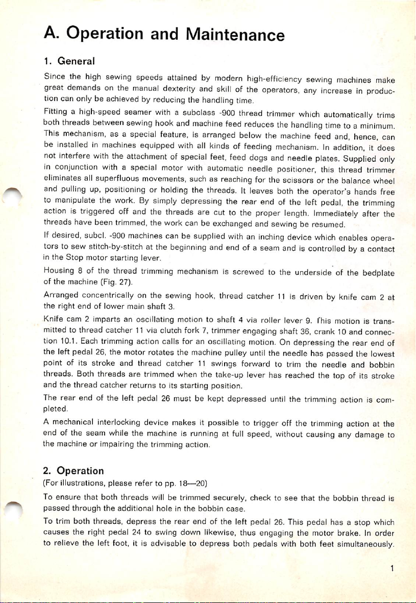
As thread catcher 11 swings forward, its tip
enters
the needle thread loop so
that
the bobbin
thread and the left leg of the needle thread loop contact its left flank, while the right leg
of
the
needle
thread
loop
contacts
its right fiank.
The thread catcher ceases to swing forward when the two threads passing to the left of its
tip have entered the
is pulled
tautbyneedle
recess
back of heel 11.1 (Fig. 1) and the thread on its right-hand
thread
retaining
edge
11.2.
W
side
Fig. 1
Page 4
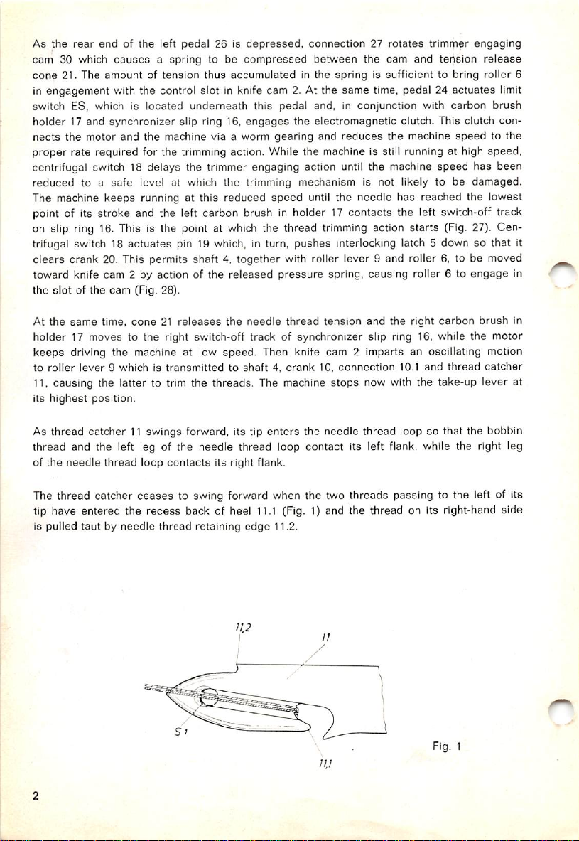
As thread catcher t1 returns to its starting position, the threads caught in the
pulled back under knife 12. Both
thread
catcher
(Fig. 1) and
the tip of the thread catcher has reached cutting
When
the
threads
and
the right switch-off track of synchronizer siip ring 16
are
severed,
can now take her foot off the left pedal. If both
are
permitted to return to their inoperative position simultaneously. It is advisable to let the
are
not
the
threads
sheared
take-up
are
protected in a groove on the
off until
lever
the
somewhat
edge
S 2 of the knife (Fig. 2).
has
reached
stops
pedals
were
depressed,
the
the machine. The
raised cutting
highest
make
recess
surface
edge
point of its
sure
are
of the
S 1 at
stroke
operator
that both
right pedai return to its starting position slightly ahead of the left because the needle will
starttodescend
In
ordertoenable
again if the right
operators
to switch from forward to
treadle
is not returned to its starting position promptly.
backward
stitching by
foot
action
on
Pfaff machines 461-900. 463-900 and 465-900, an additional feed reversing mechanism has
been mounted on feed regulating shaft (Fig. 27). When the front end of pedal 26 is depressed,
connection 27
causes
trimmer engaging cam 30 to turn forward and this motion is transmitted
to feed reversing crank 33 by means of a two-part connection.
On Pfaff machines 467-900 and 469-900, the top or differential feed can be controlled by de
pressing the front end of the left pedal. The reverse feed control of these machines must be
operated
by hand.
3.
Maintenance
A careful adjustment of the trimming mechanism
ensures
trouble-free operation.
Ail screws must be tightened securely. This applies especially to the screws on knife cam 2,
roller lever 9 and thread catcher driving crank 10 since these parts are subjected to abrupt
stress.
Special
especially between sewing hook and needle plate, are
care
should be taken that
the
dust
and lint which accumulate in this mechanism,
removed
with
a soft brush each day
the machine is in operation. By the same token, ail moving parts should be oiled daily.
When
oiling
all
moving
parts of the
trimming
mechanism each day, check to see that cen
trifugal switch 18, pin 19 and latch 5 move freely. Make particularly sure that synchronizer
slip ring 16 is
Be
suretooil
kept
the
free
from oil.
somewhat
concealed
roller6on
roller
lever
9.
Page 5
B.
Adjustment
It is
recommendedtouseagauge
catcher
No. 129 567,
which is available under No. 129 499. A
canbesupplied
for
In checking the various settings, be
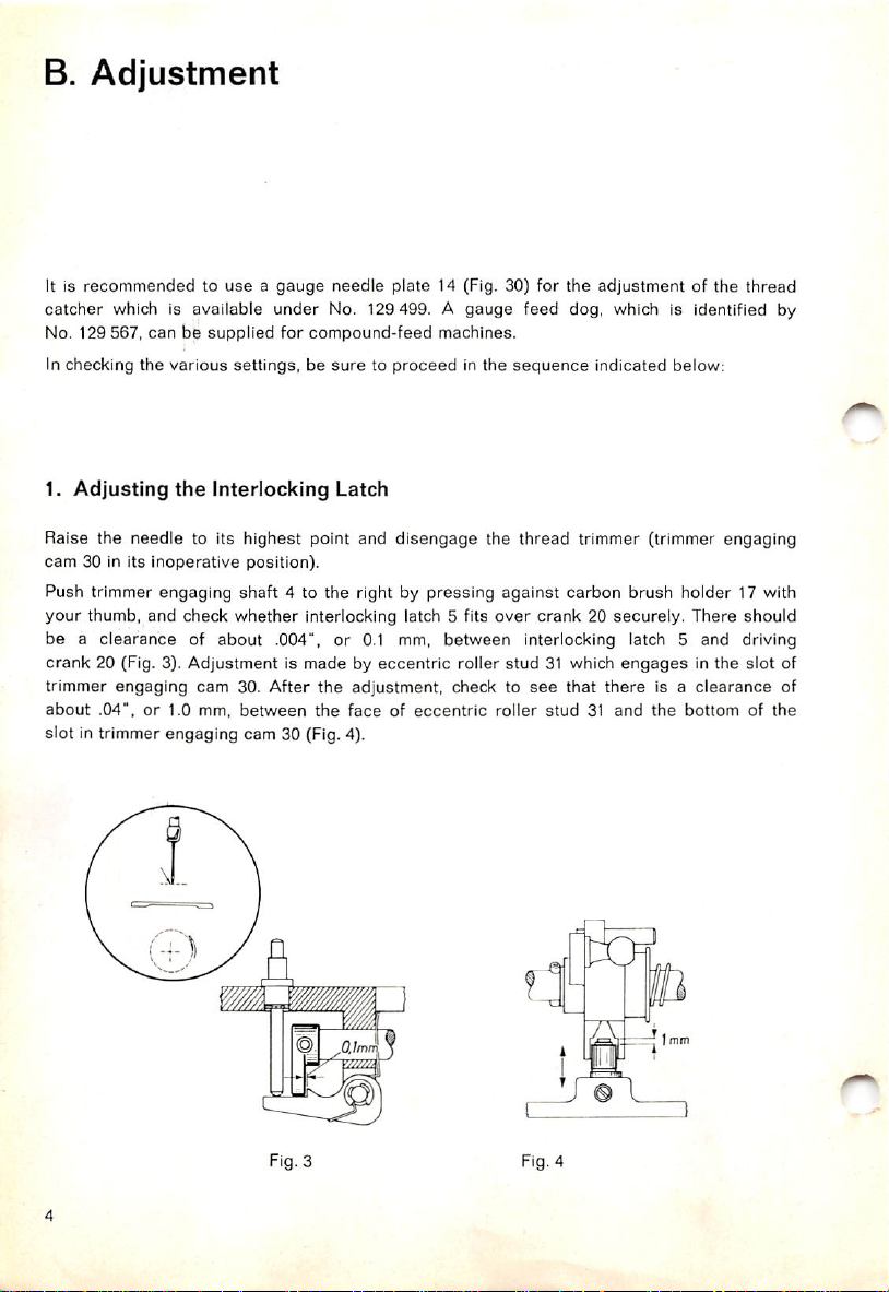
1.
Adjusting
the
Interlocking
needle
plate
compound-feed
suretoproceed
Latch
14 (Fig. 30) for
gauge
feed dog, which is identified by
machines.
in the
sequence
the
adjustmentofthe
indicated below:
thread
Raise the needle to its highest point and
cam
30 in
its
inoperative
Push trimmer engaging
your
thumb,
and
be a
clearanceofabout
crank
20 (Fig. 3). Adjustment is made by eccentric roller stud 31 which
trimmer
about
engaging
.04",or1.0
check
cam
mm,
position).
shaft
4 to the right by pressing
whether
interlocking latch 5 fits
.004", or 0.1 mm, between interlocking latch 5 and driving
30.
After
the
between
the
disengage
adjustment,
faceofeccentric
check to
the thread trimmer (trimmer engaging
slot in trimmer engaging cam 30 (Fig. 4).
Fig. 3 Fig. 4
against
carbon brush holder 17 with
over
crank20securely.
see
that
roller
stud31and
j©l
engages
there
There
in the slot of
is a
clearance
the
bottomofthe
should
of
Page 6
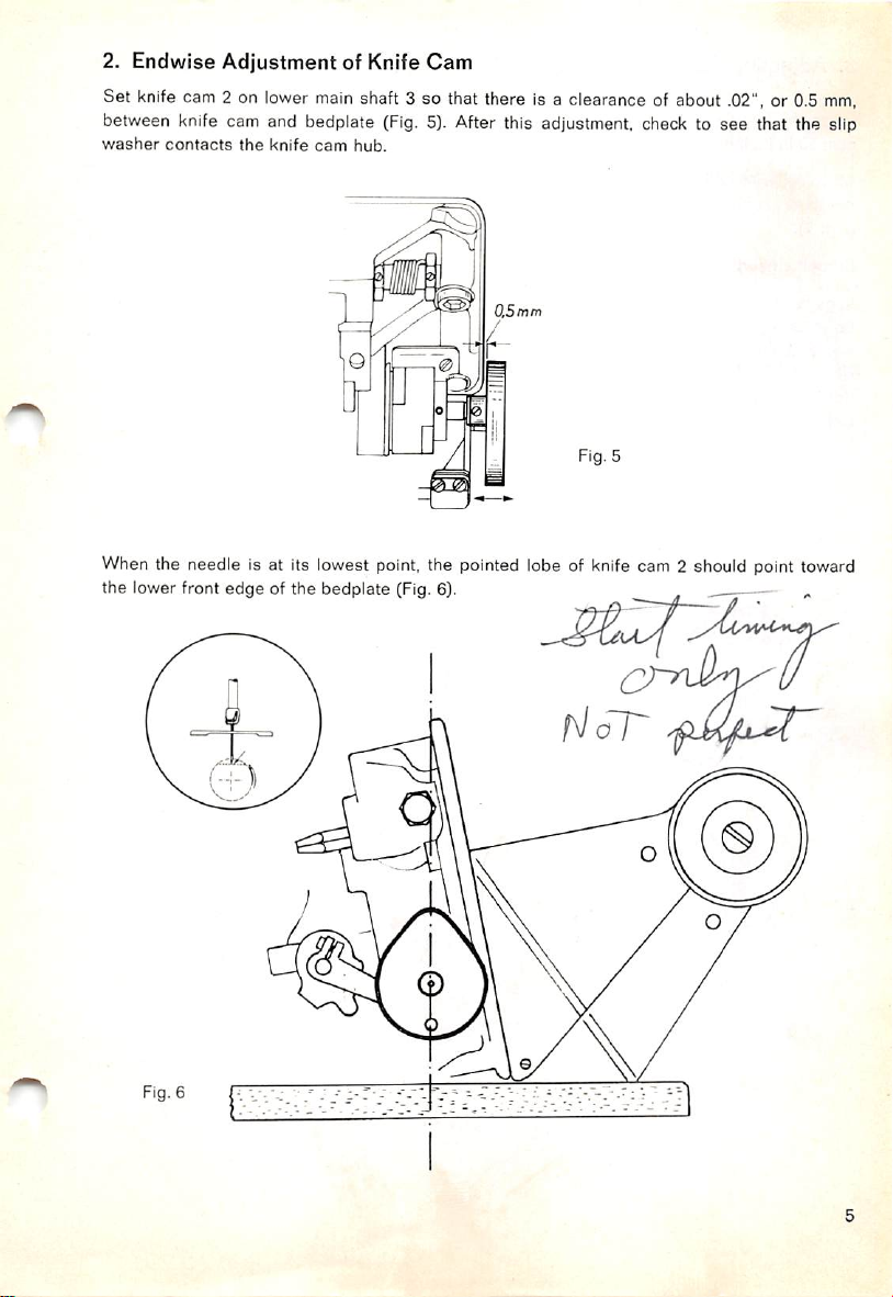
2.
Endwise
Set knife cam 2 on lower main shaft 3 so that there is a clearance of about .02", or 0.5
Adjustment
of Knife
Cam
mm,
between knife cam and bedplate (Fig. 5). After this adjustment, check to see that the slip
washer
contacts
the
knife
cam
hub.
O.Smm
Fig. 5
When the needle Is at its lowest point, the pointed lobe of knife cam 2 should point toward
the lower front
edgeofthe
bedplate (Fig. 6).
Fig. 6
a/ oT^
Page 7
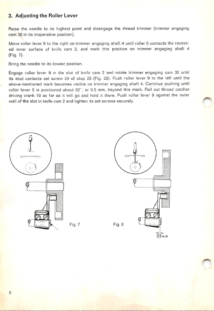
3.
Adjusting
the
Roller
Lever
Raise the needle to its highest point and
cam
30 in its
inoperative
position).
Move roller lever 9 to the right on trimmer engaging
ed inner
(Fig. 7).
Bring
the
surface
needle
of knife cam 2, and mark this position on trimmer engaging
to its
lowest
position.
disengage
the thread trimmer (trimmer engaging
shaft
4 until roller 6
contacts
the
recess
shaft
Engage roller lever 9 in the slot of knife cam 2 and rotate trimmer engaging cam 30 until
set
its stud contacts
above-mentioned mark
screw 29 of stop 28 (Fig. 28). Push roller lever 9 to the left until the
becomes
visible on trimmer engaging
shaft
4. Continue pushing until
roller lever 9 is positioned about 02", or 0.5 mm, beyond this mark. Pull out thread catcher
driving crank 10 as far as it will go and hold it there. Push roller lever 9 against the outer
wall of
the
slot
in knife
cam2and
tighten
its
set
screws
securely.
4
Fig. 7 Fig. 8
Page 8
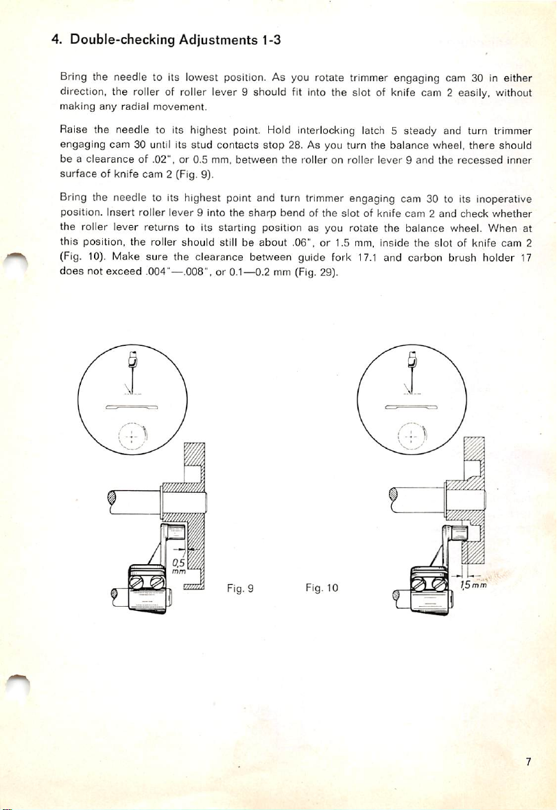
4. Double-checking
Adjustments
1-3
Bring the needle to its lowest position. As you rotate trimmer engaging cam 30 in either
direction, the roller of roller lever 9 should fit into the slot of knife cam 2 easily, without
making
any
radial
movement.
Raise the needle to its highest point.
engaging
beaclearance
cam
30 until its
of .02",or0.5 mm,
stud
contacts
stop
between
Hold
interlocking latch 5 steady and turn trimmer
28. As you turn the
the
rolleronroller
balance
lever9and
wheel,
the
recessed
there
should
surface of knife cam 2 (Fig. 9).
Bring
the needle to its highest point and turn
position.
Insert
roller
lever
9 into
the
sharp
bend
trimmer
of the
engaging cam 30 to its inoperative
slot
of knife
cam
2 and check
whether
the roller lever returns to its starting position as you rotate the balance wheel. When at
this position, the roller should still be
(Fig. 10). Make sure the clearance between guide fork
about
.06", or 1.5 mm, inside the slot of knife cam 2
17.1
and carbon brush holder 17
does not exceed .004"—.008", or 0.1—0.2 mm (Fig. 29).
inner
Fig. 9
Fig. 10
]Sfnm
Page 9

5. Adjusting
Remove
presser
the
foot,
Thread
needle
Catcher
plate
and
feed
dog.
Thread catcher 11 should besopositioned that its tip is in line with
needle,asviewed
Adjustmentismadebythe
Lower the
contacts
stroke.
of bobbin
driving
stop
Whenatthis
case
crank
from
above
(Fig. 11).
two
thread
catcher
set
screws.
needletothe
28.
Rotate
position,
bottom of its
the
balance
the
rear
stroke
wheel
edge
and turn trimmer
until
thread
catcher11has
of its
cutout
should
engaging
be in line with
position finger 13 (Fig. 12). If adjustment is required, reposition thread
10.asappropriate.
the
left
cam
30 until its
completed
the
side
of the
stud
its forward
front
edge
catcher
Fig. 11
6.
Adjusting
Bring
the
stop
28. Rotate the
or 2.0 mm,
this
position,
center
line of
needle
past
the
the
to its
the
tip of
bobbin
Knife
lowest
balance
center
thread
case
Cam
point
and
wheel until the heel of the thread pull-off flange is positioned Vti".
line of
bobbin
catcher11shouldbepositioned
position finger 13,
and the thread pull-off flange being about
Fig. 12
turn trimmer
case
position finger 13. With
the
total
V35",
or 4.0 mm (Fig. 13).
engaging
clearance
-f\-r
i
/
cam
between
>•
•
30 until its
the
or 2.0 mm,
thread
Fig.
stud
sewing
shortofthe
13
contacts
hook
catcher
at
11
Page 10

7. Adjusting
Bring the needle to its lowest point.
There should be a clearance of
side of the needle (Fig.14). Set knife 12 sideways so that it is centered above the thread
catcher tip.
right recessed edge of thread catcher11(Fig,15).
Make
the
Knife
particularly
764",
sure
or 3.5
though
mm.
between the tip of
that its
Fig. 14
right
edge does not
knife
12 and the obverse
protrude
from
the
35
mm
Fig. 15
8. Checking the Trimming Action
(Double-Checking Adjustments 5 and 7)
To make sure that
threadistrimmed,9?>rrectlytothe
(Fig. 1). If adjustment is required, loosen both set screws of the thread catcher and readjust,
as
instructedinpar.5above.
aread
catcher11is not inclined sideways
right
and
right
wrong
Fig. 16
leftofthe
(Fig,
highest
wrong
16), check whether the
pointofcutting
edge
8 1
Page 11

9. Preliminary Adjustment of the Synchronizer Slip Ring
Lower
the
inoperative
needletothe
position.
bottom of its
stroke
and
turn trimmer
engaging
cam
30 to its
The left carbon brush should be so positioned on the left switch-off track that there is a
clearance of .04", or 1.0
mm,
between its right side and the right edge of the track (Fig. 17).
When the needle has reached the lowest point of its stroke, the left carbon brush should
be positioned about
In
the direction of rotation
16onlower
main
^^32",
shaft3,as
or 10
mm,
(Fig,
18).
appropriate.
past the near end of the left switch-off track, as seen
If adjustment is required, rotate synchronizer slip ring
:T
[_l^
Fig. 17
10.
Adjusting
Adjust centrifugal switch 18
19
nor
the
stud
the
Centrifugal
of trimmer
sideways
engaging
Switch
so that it strikes neither the bushing of
cam
30 (Fig. 19).
Fig. 18
pressure
pin
When the beginning of the left switch-off track of slip ring 16 reaches the carbon brush,
interlocking latch 5 should be released already. It should remain released until the carbon
brush
has
reached
on
lower
main
shaft
the
end of
3 (Fig. 27).
the
switch-off track. To
adjust,
rotate
centrifugal switch 18
Fig. 19
10
Page 12

11. Timing
the
Needle
Thread
Tension
Release
Attach feed dog, needle plate and
The needle thread tension should be
presser
released
foot, and lower the latter onto the needle plate.
when trimmer engaging
shaft
4 has completed
about one half of its travel. Adjustment is made by loosening binding screw 22 and lengthen
ing or shortening the connection (Fig. 20). When trimmer engaging
left-hand position,
12.
Checking
(Pfaff
Set
the
machine
reverse
pushing
trackoftrimmer
feed
the
the
machines
for its
control.
two-part
engaging
the
needle
thread
Operationofthe
461,
463
and
longest
Turn
trimmer
connection
cam30must
tension
465)
stitch
engaging
together
mustbeoperative.
Reverse
and
reverse
completely. As you do this,
not
move
Feed
the
direction of
cam30downwards
beyond
the
shaft
Fig. 20
Mechanism
feedbydepressing
away
the
center
line of
4 is at its extreme
from
stop
28,
thus
end of
the
channel
guide
roller 31
the
(Fig. 21). If adjustment is required, turn feed reversing crank 33 on the feed regulating shaft,
as
mayberequired.
11
Page 13

13. Adjusting
To
set
pedals
of
motor
connection
the
Motor
Connection
24 and 26 in the most convenient position for operation,
25,asappropriate.
adjust
the length
If it should become necessary later to adjust the position of one of the pedals or of the
motor, follow
14.
Adjusting
Bring
the
the
needle
instructions
the
Trimmer
to its
lowest
given in
Connection
point.
par.
14 below.
Push the top end of two-part connection 27 onto the ball stud of trimmer engaging cam 30.
Rotate this cam until it contacts stop 28 and depress the rear ends of both pedals as far as
they will go. With the pedals in this position, the ball cup at the lower end of connection 27
shouldbepositioned
distance,asillustrated in Fig. 22).
about
.04", or 1 mm,
below
1mm
the ball
studonthe
pedal
(center-to-center
15.
Checking
Set
the machine for its longest stitch and
this,
the
reverse
Depress
pedal.
As you do this, roller
settings
Both
12
the
Pedal
feed
control
the
rear
end
of the left
canbeadjustedbythe
Operation
must
lever9must
not
pedal
stop
depress
make
any
26 until its
not
make
screwonthe
Fig. 23
the tip of the right pedal 24. As you do
perceptible
stop
any motion
engages
right
motion.
toward
pedal
the
undersideofthe
knife
cam
(Fig. 23).
2.
right
Page 14

16. Adjusting
the
Limit Switch
Position
before the switch operating lever
17. Final Adjustment of
limit
switch ES in the elongated holes of its bracket so that it
contacts
Fig. 24
the
Its
stop
(Fig. 24).
LAJ~
Synchronizer Slip Ring
will
be actuated shortly
Switch on the motor and depress the rear ends of both pedals. When the threads have
been trimmed, the needle should stop with its point about Vu", or 8.0 mm, above the needle
plate. To adjust, reposition synchronizer slip
par. 9, making particularly sure that Its lateral position is correct.
ring
16 on lower
main
shaft 3, as instructed in
13
Page 15

C. Trouble
1.
Machine
1.01
1.02
1.03 knife 12 Is
thread
thread
failstotrim
catcher
catcher
Shooting
the
threads
because
11 is
set
incorrectly in relation to knife 12,
11 is
set
incorrectly
set
incorrectly in relation to the needle,
in relation to the
needle,
1.04 the setting of synchronizer slip ring 16 has been disturbed,
1.05
knife
cam
2 is
out
of time,
1.06 centrifugal switch 18 fails to release the trimming mechanism,
1.07 limitswitch ES under the right pedal does not work properly,
1.08 trimmer engaging cam 30 does not make its complete travel,
1.09
the
knife
is blunt,
1.10 knife 12 does not press against thread catcher11sufficiently,
1.11
shaft4jams,
1.12 the thread
catcher
jams,
1.13 the bobbin thread has not been passed through the additional hole in the bobbin case.
1.14 thread catcher
11
is set too close to the sewing hook.
2. Machine trims threads repeatedly because
2.01
the
motor
clutchisdefective,
2.02
the
carbon
brushisnot
slip ring,
centered
correctly
on the
switch-off
track
2.03 the carbon grit has formed a "bridge" (or connection),
2.04 shaft 4 jams and does not complete its travel,
2.05 trimmerengaging cam 30 does not make its complete turn,
2.06 the line voltage fluctuates excessively,
2.07
the
motor
clutchissoiled
3. Actuatingthe pedal does not start the
3.01
limit
switchESunderthe
with oil.
right
trimming
pedal
action because
failstoswitch
inthe
trimming
3.02 trimmerengaging cam 30 does not make its complete turn,
3.03
shaft
4 jams,
3.04 the setting of synchronizer slip ring 16 has been disturbed,
3.05 roller6of roller lever9 does not run inthe groove of knifecam 2.
3.06 centrifugalswitch 18 is out of adjustment,
3.07 the motor clutch jams.
14
of the
synchronizer
mechanism,
Page 16

4.
Needle
thread
end
too
short
because
4.01
the
upper
tension
is not
open
during
the
trimming action,
4.02 the needle thread is considerably
4.03 the
4.04
4.05
5.
threads
are
trimmed before the take-up lever has reached the top of its stroke,
thread catcher11is adjusted incorrectly so that all three threads are caught behind
heel
the
Bobbin
11.1onthe
extra
thread
left-hand
springinthe
end
too
short
upper
because
retarded
sideofthe
tensionistoo
thread
as it
catcher,
strong.
enters
the upper tension,
5.01 the
5.02 the
6.
Needle
reduced
bobbin
thread
speedofthe
thread
is not
end
too
long
machine is
too
severedbythe
because
high,
cutting
edge
provided
for
this
purpose.
6.01 the extra spring in the upper tension is missing or too weak.
7.
Needle
thread
end
7.01 it
Thread
8.
8.01 the
was
held
kinks
upper
liesonmaterial
downbythe
at beginning of
tension
does
because
presser
foot.
seam
because
not work properly,
8.02 an excessive amount of thread was pulled through/the upper tension for the
action.
9.
Thread
ends
too
long
because
9.01 knife 12 has been adjusted improperly.
to.
Work
10.01
cannotberemoved
the
threads
were
not
from
trimmed,
under
the
presser
foot
because
10.02 the needle thread end is jammed between sewing hook and thread catcher
10.03
the
needleisset
too
low.
trimming
11
11.
Needle
set
too
low
after
trimming
11.01
synchronizer slip ring 16 is adjusted incorrectly,
11.02
the
voltage
fluctuates,
11.03
the
motor
clutchissoiled
12.
Needle
enters
material
after
because
with
oil.
left
pedalisreleased
because
12.01 limit switch ES under the right pedal 24 is adjusted incorrectly.
12.02 connection 27 between pedal 26 and the trimming mechanism is too long.
15
Page 17

D.
1.
1.
2.
3.
4.
Annex
Pedal
(on Pfaff
Depress
Depress
Depress
Depress
Operation
machines
tip of right pedal 24
heel of right pedal 24
tips of both pedals 24 and 26
heels
461-900;
463-900; 465-900;
of both pedals 24 and 26
and
467/469-900)
Fig. 25
Machine
Needle
Machine
sews
forward
movestoiowest
sews
backward
position
Needle moves to highest position
and
both
threads
are
trimmed.
16
Page 18

(on Pfaff
machines
467-900
and
469-900)
Fig. 26
Depress
1.
2.
Depress
3.
Depress
Depress
4.
2. Tilting
To tilt
mechanism.
tip of right
heel
tipsofboth
heelsofboth
the
the
machine
Never
pedal
of right
Machine
back,
start
24
pedal
24
pedals24and
pedals24and
Back
remove
the
connection
machine
26
26
before
connection27has
27 which
Machine
Needle
Machine
Needle
both
threads
connects
sews
forward
movestolowest
gathers
movestohighest
are
trimmed.
pedal
26 to
been
replaced
position
position
the
because
and
trimming
there
is a danger that the trimming action may have been triggered off and the trimmer may be
damagedbythe
When the connection has
high
starting
speedofthe
been
replaced, a
machine.
stoponthe
left pedal automatically switches
off the trimming mechanism at the beginning of the sewing action.
17
Page 19

Fig. 27
The trimming mechanism is disengaged.
2 idles, and interlocking latch 5 interlocks
20
3^
R
Shaft
4 is at its extreme left position, knife cam
stop
20.
9396
Fig. 28
The trimming mechanism is engaged. Interlocking latch 5 has
been
lifted
R9397
clearofstop
20,
shaft 4 has moved to its extreme right position, and roller 6 on roller lever 9 is engaged In
the
grooveofknife
18
cam
2.
Page 20

s
Fig. 29
Worm's
Fig.30 R
This is how gauge needle plate 14 is applied to adjust thread catcher 11 and knife 12.
eye
viewofcomplete
thread
trimming
mechanism
5
mm
9391
R9395
19
Page 21

Fig. 31
Power
table
mechanism.
equipped
Pedalsintheir
with
special
operative
motor
position.
for
high-speed
R9398
seamers
fitted with
thread
trimming
Fig. 32
R9399
Power table fitted with special motor. Pedals swung up to facilitate cleaning the floor or
moving
the
tabletoanother
20
location.
Page 22

Contents
A.
Operation
1.
General
2.
Operation
3.
Maintenance
B.
Adjustment
1. Adjusting the Interlocking Latch
2. Endwise Adjustment of Knife Cam
3. Adjusting the Roller Lever
4. Double-checking Adjustments 1—3
5. Adjusting the Thread
6. Adjusting
7. Adjusting
8.
Checking
9. Preliminary Adjustment of the Synchronizer Slip Ring .
10. Adjusting the Centrifugal Switch
11. Timing the Needle Thread Tension Release . . . .
12. Checking the Operation of the Reverse Feed Mechanism .
13. Adjusting
14. Adjusting
15. Checking the Pedal Operation
16.
Adjusting
17. Finai Adjustment of the Synchronizer Slip Ring
and
Maintenance
the
Knife Cam
the
Knife
the
Trimming Action
the
Motor
the
Trimmer
the
Limit
Catcher
Connection
Connection
Switch
4
5
6
7
8
8
9
9
10
10
11
11
12
12
12
13
13
C.
Trouble
1.
Machine
2.
Machine
3. Actuating
4.
Needle
5.
Bobbin
6.
Needle
7.
Needle
8.
Thread
9.
Thread
10.
Work
11.
Needle
12.
Needle
D.
Annex
1.
Pedal
2. Tilting
3.
Thread
Shooting
failstotrim
trims
the
thread
thread
thread
thread
kinks at
ends
cannot
set
too
enters
Operation
the
Machine
Trimmer
the
threads
pedal
end
end
doesnostart
too
end
too
end
too
liesonmaterial
repeatedly
short
short
long
beginningofseam
too
long
be
removed
low
after
trimming
material
after
.
Back
Illustrations
threads
left
pedalisreleased
.
the
trimming
....
....
action
.
14
14
14
15
15
15
15
15
15
15
15
15
16
17
18—20
21
Page 23

Page 24

r<
Page 25

Page 26

Z
2^
7
5.J'
-I
'*.
•
v:f-.r
.1- .
V," I
'_>• f
••.
®
(PFAFF)
o
Nr. 12310
engl.
R 466
Printed in Germany
 Loading...