

Page 1

118 1
118 3
Adjustment Manual
1181-D
1183-D
This Adjustment Manual is valid for machines from the
following serial numbers onwards:
# 6 001 000
296-12-18 710/002
Justieranleitung engl. 06.04
Page 2

The reprinting, copying or translation of PFAFF Service Manuals, whether in whole or in part,
is only permitted with our previous authorization and with written reference to the source.
PFAFF Industrie Maschinen AG
Postfach 3020
D-67653 Kaiserslautern
Königstr. 154
D-67655 Kaiserslautern
Page 3

Contents
Contents ...............................................................................Chapter - Page
13 Adjustment ............................................................................................................. 13 - 1
13.01 Tools, gauges and other accessories for adjusting................................................... 13 - 1
13.02 Abbreviations ........................................................................................................... 13 - 1
13.03 Explanation of the symbols ...................................................................................... 13 - 1
13.04 Checking and adjusting aids ..................................................................................... 13 - 2
13.05 Adjusting the basic machine .................................................................................... 13 - 3
13.05.01 Basic position of the machine drive ......................................................................... 13 - 3
13.05.02 Preadjusting the needle height................................................................................. 13 - 4
13.05.03 Bottom feed neutral position.................................................................................... 13 - 5
13.05.04 Neutral position of the needle feed (only on PFAFF 1181) ....................................... 13 - 6
13.05.05 Bottom feed lifting motion ....................................................................................... 13 - 7
13.05.06 Bottom feed dog height ........................................................................................... 13 - 8
13.05.07 Feed dog motion of bottom feed dog ...................................................................... 13 - 9
13.05.08 Feeding motion of needle feed (only on PFAFF 1181).............................................. 13 -10
13.05.09 Needle in needle hole center (only on PFAFF 1183) ................................................. 13 - 11
13.05.10 Needle to needle hole centre (on PFAFF 1181) ........................................................ 13 - 12
13.05.11 Synchronous strokes of needle- and drop feed (only on PFAFF 1181) ..................... 13 -13
13.05.12 Hook shaft bearing and toothed belt tension ........................................................... 13 - 14
13.05.13 Hook lubrication ....................................................................................................... 13 -15
13.05.14 Needle rise, hook-to-needle clearance, needle height and bobbin case position finger 13 - 16
13.05.15 Thread check spring and slack thread regulator ....................................................... 13 -17
13.05.16 Position of knee lever............................................................................................... 13 -18
13.05.17 Knee lever stop ........................................................................................................ 13 -19
13.05.18 Bobbin winder .......................................................................................................... 13 - 20
13.05.19 Limiting the stitch length.......................................................................................... 13 -21
13.05.20 Stitch length adaptation ........................................................................................... 13 -22
13.05.21 Presser foot pressure .............................................................................................. 13 - 23
13.05.22 Modifying the needle bar stroke .............................................................................. 13 - 24
13.06 Adjusting the edge trimmer –731/01........................................................................ 13 -25
13.06.01 Zero position of the knife ......................................................................................... 13 -25
13.06.02 Cutting motion ......................................................................................................... 13 -26
13.06.03 Knife height.............................................................................................................. 13 -27
13.06.04 Knife position in sewing direction............................................................................. 13 -28
13.06.05 Knife position crosswise to sewing direction ........................................................... 13 -29
13.07 Adjusting the thread trimming device -900/24.......................................................... 13 -30
13.0.01 Adjusting the solenoid / preliminary adjustment of the control cam......................... 13 -30
13.07.02 Lateral alignment of the thread catcher ................................................................... 13 - 31
13.07.03 Knife position ........................................................................................................... 13-32
13.07.04 Front point of reversal of the thread catcher ............................................................ 13 - 33
13.07.05 Manual trimming check............................................................................................ 13 -34
Page 4

Contents
13.07.06 Needle thread tension release ................................................................................. 13 - 35
13.07.07 Readjusting the control cam .................................................................................... 13 - 36
13.08 Adjusting the thread wiper -909/04 .......................................................................... 13 - 37
13.08.01 Thread wiper movement.......................................................................................... 13 - 37
13.08.02 Thread wiper position............................................................................................... 13 - 38
13.09 Adjusting the automatic presser foot lift -910/06 ..................................................... 13 -39
13.10 Adjusting the back-tacking mechanism –911/37 ...................................................... 13 - 40
13.11 Parameter settings................................................................................................... 13 - 41
13.11.01 Selecting the user level............................................................................................ 13 - 41
13.11.02 Example of a parameter input .................................................................................. 13 -42
13.11.03 Liste der Parameter ................................................................................................. 13 - 43
13.11.04 Reset / Cold start ..................................................................................................... 13 - 44
13.12 Internet update of the machine software................................................................. 13 - 45
13.13 Explanation of the error signals ................................................................................ 13 - 46
Contents ...............................................................................Chapter - Page
14 Circuit diagrams ..................................................................................................... 14 - 1
Page 5

13 Adjustment
On the PFAFF 1181 and 1183 do not use a screw clamp on the needle bar! The
special coating of the needle bar could be damaged.
Please observe all notes from Chapter 1 Safety of the instruction manual! In
particular care must be taken to see that all protective devices are refitted
properly after adjustment, see Chapter 1.06 Danger warnings of the
instruction manual!
If not otherwise stated, the machine must be disconnected from the electrical
power supply.
All following adjustments are based on a fully assembled machine and may only be carried
out by expert staff trained for this purpose.
Machine covers, which have to be removed and replaced to carry out checks and
adjustments, are not mentioned in the text.
The order of the following chapters corresponds to the most logical work sequence for
machines which have to be completely adjusted. If only specific individual work steps are
carried out, both the preceding and following chapters must be observed.
Screws, nuts indicated in brackets ( ) are fastenings for machine parts, which must be
loosened before adjustment and tightened again afterwards.
Adjustment
13.01 Tools, gauges and other accessories for adjusting
● 1 set of screwdrivers with blade widths from 2 to 10 mm
● 1 set of wrenches with jaw widths from 7 to 14 mm
● 1 set of Allan keys from 1.5 to 6 mm
● 1 metal rule, (Part No. 08-880 218-00)
● 1 feed dog adjustment gauge, Part No. 61-111 639-71
● 1 adjustment pin (5 mm dia.), Part No. 13-033 346-05
● Adjustment gauge, part No. 61-111 639-70
● 1 adjustment gauge for tightening the hook drive belt, Part-No. 61-111 639-76
● Sewing thread and test material
13.02 Abbreviations
TDC = top dead center
BDC = bottom dead center
13.03 Explanation of the symbols
In this adjustment manual, symbols emphasize operations to be carried out or important
information. The symbols used have the following meaning:
Note, information
Service, repair, adjustment, maintenance
(work to be carried out by qualified staff only)
13 - 1
Page 6
Adjustment
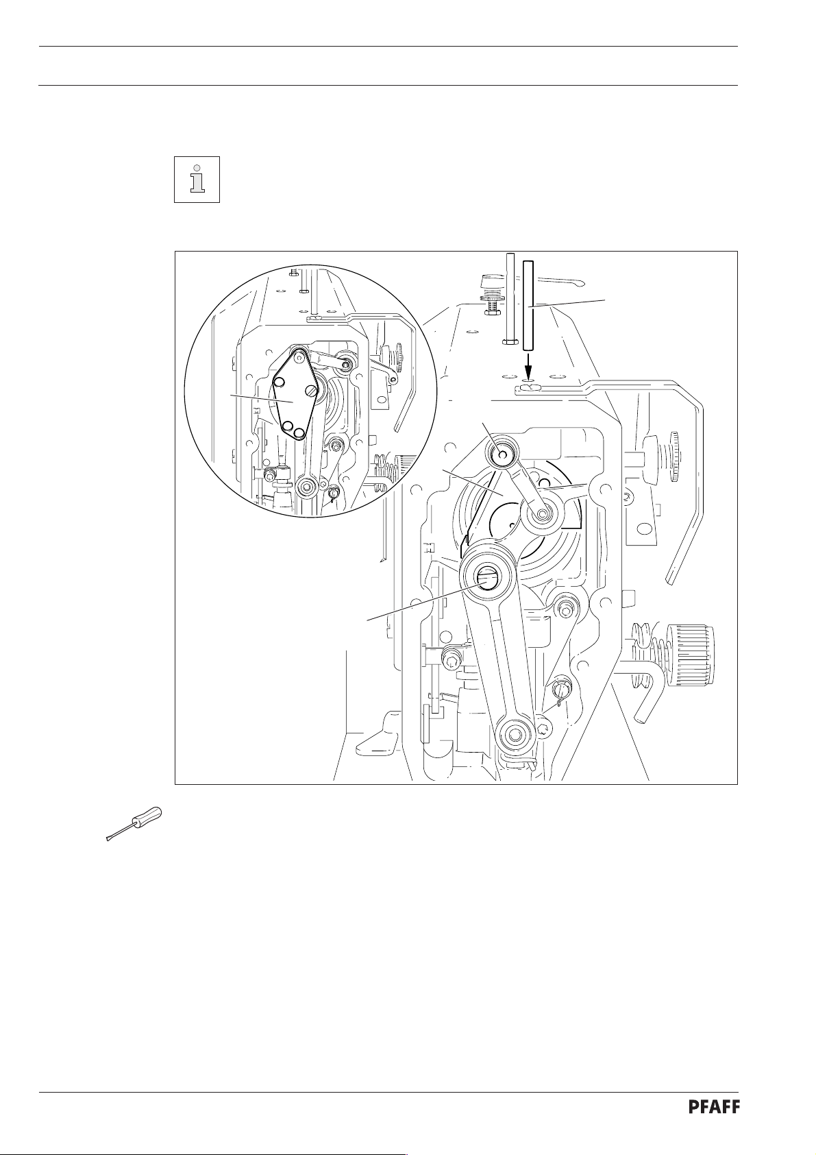
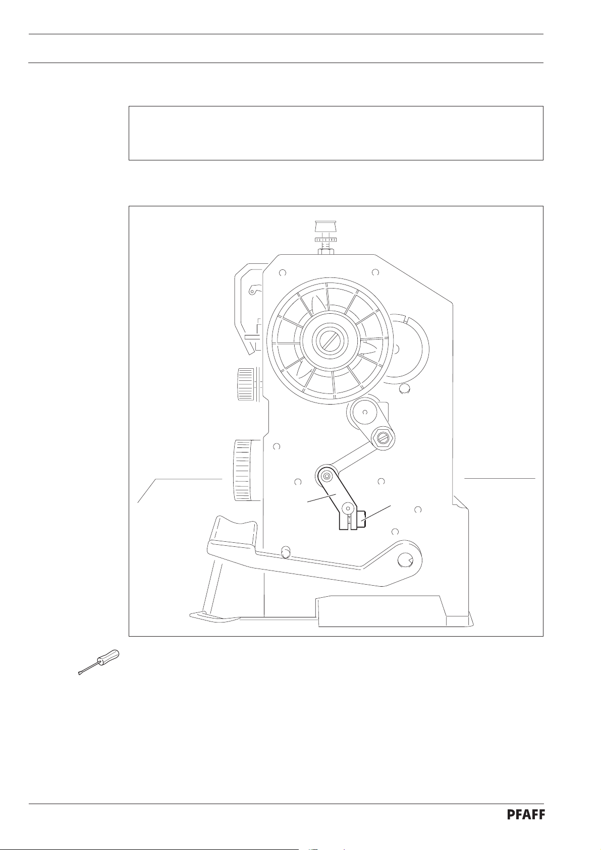
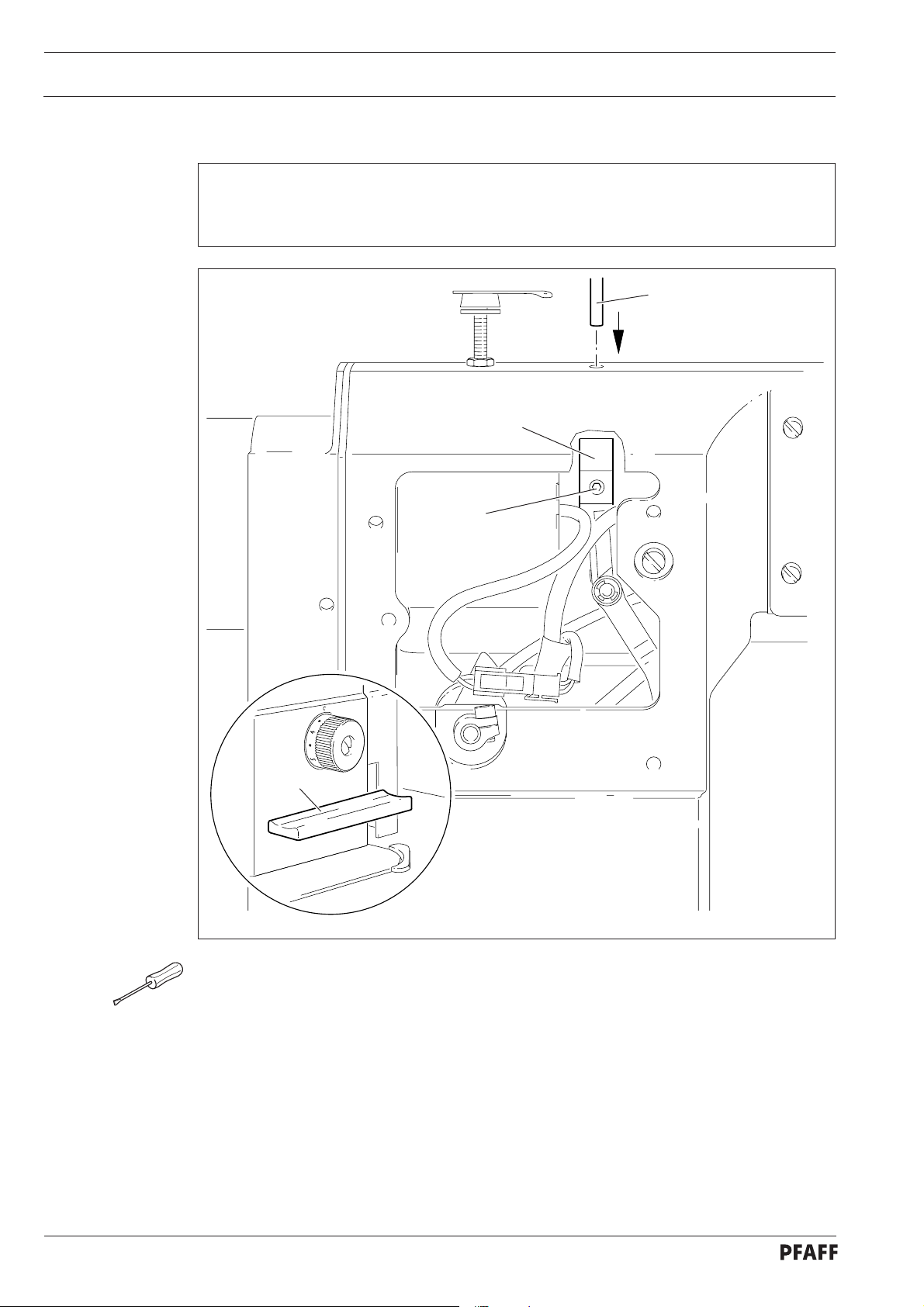
13.04 Checking and adjusting aids
With the aid of blocking pin 1 (part No. 13-033346-05) and if necessary
adjustment gauge 3 (part No. 61-111 639-70) the machine can be blocked in the
following positions for adjustment
1
3
4
2
5
Fig. 13 - 01
Needle bar position 1.8 mm past b.d.c.
● Turn balance wheel until needle bar is roughly in required position
● Insert blocking pin 1 in hole
● Turn balance wheel slightly back and forth until blocking pin engages crank 2
13 - 2
Needle bar position 0.6 mm past t.d.c.
● Set needle bar roughly at required position
● Place adjustment gauge 3 onto pins 4 and 5, making sure right side is used (for 30 or 36
mm needle bar stroke)
Needle bar position 0.6 mm past b.d.c.
● Set needle bar roughly at required position
● Place adjustment gauge 3 onto pins 4 and 5, making sure right side is used (for 30 or 36
mm needle bar stroke)
Page 7
.05 Adjusting the basic machine
13
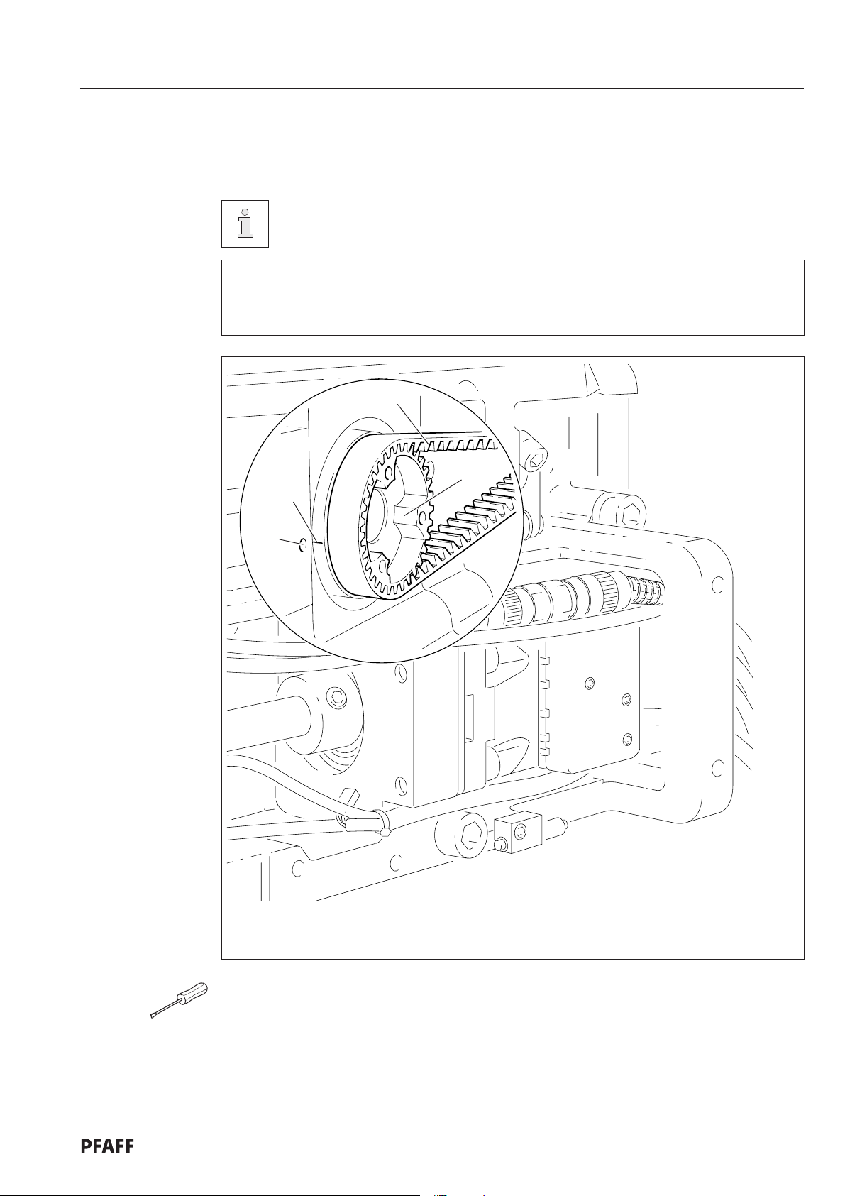
13.05.01 Basic position of the machine drive
This adjustment is only required if toothed belt 2 has been removed.
Requirement
When the needle bar position is 0.6 mm above the BDC, the marks on the machine
housing 3 and toothed belt wheel 1 must be flush with each other.
2
1
4
Adjustment
3
Fig. 13 - 02
57-42a
● Set needle bar at 0.6 mm past b.d.c.
● Turn toothed belt sprocket 1 according to Requirement and push on toothed belt 2.
13 - 3
Page 8
Adjustment
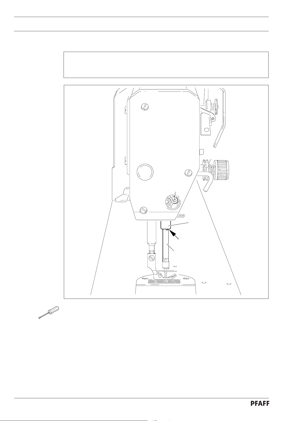
.05.02 Preadjusting the needle height
13
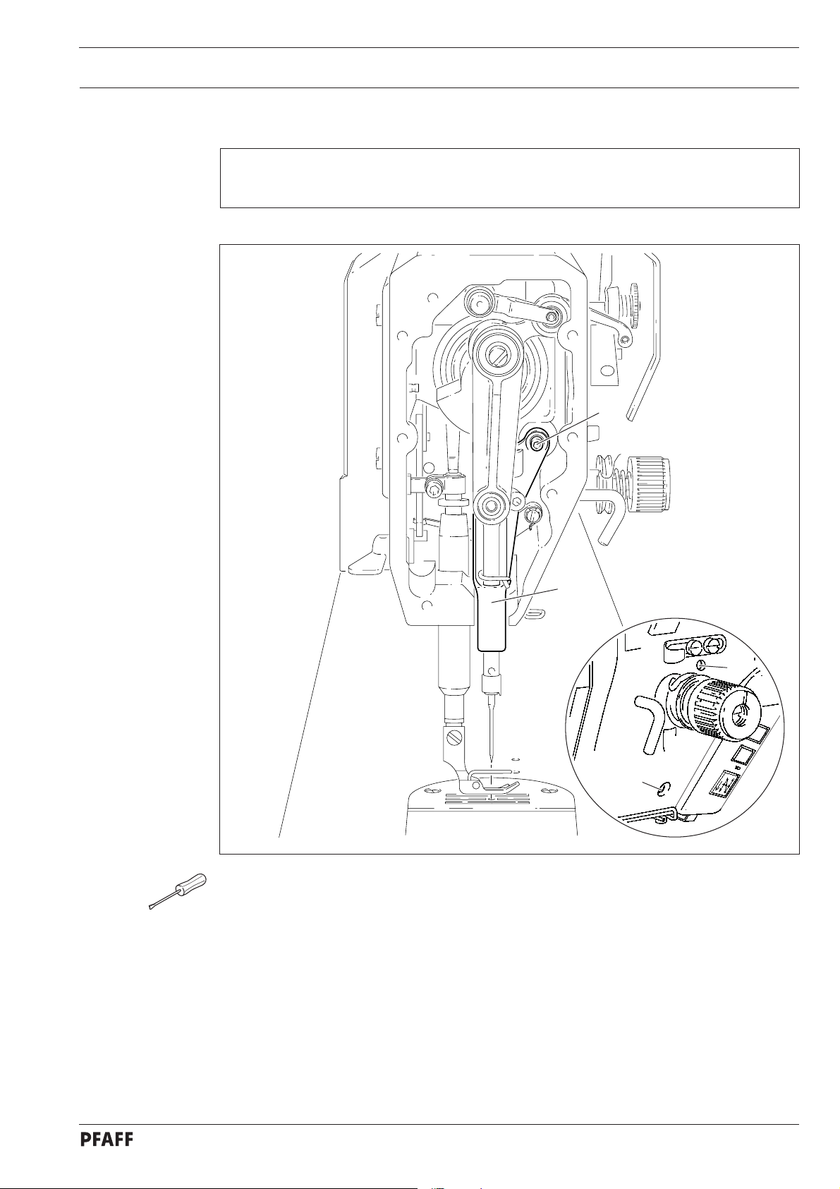
Requirement
When the needle bar is positioned 1.8 mm above BDC, the mark on the needle bar 1 must
be flush with the bottom edge of the needle bar frame 3.
2
3
1
Fig. 13 - 03
● Set needle bar at 1.8 mm past b.d.c. and block machine with blocking pin, see
Chapter 13.04 Checking and adjusting aids.
● Move needle bar 1 (screw 2), without turning it, according to the requirement.
13 - 4
Page 9
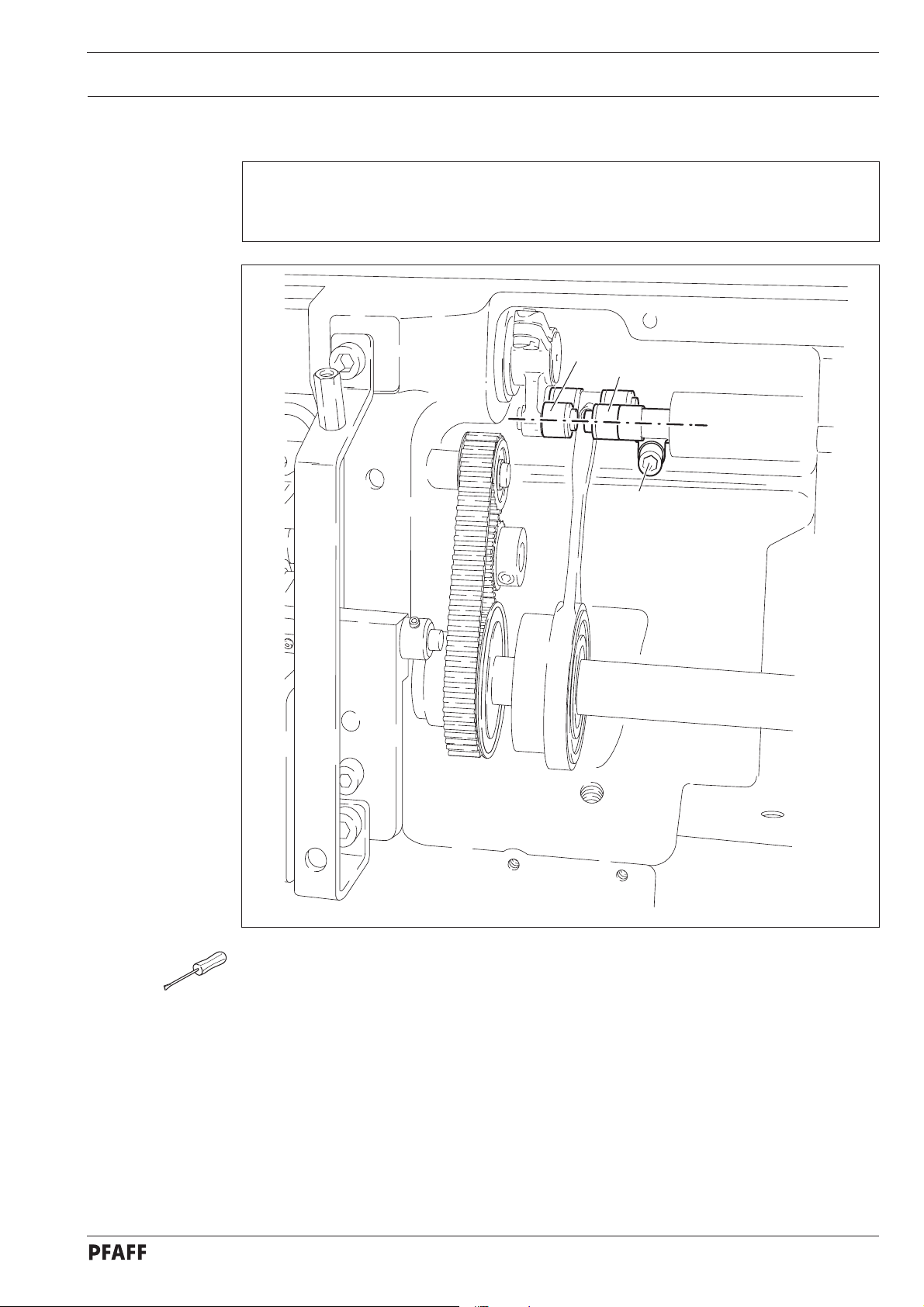
05.03 Bottom feed neutral position
13.
Requirement
At stitch length setting "0", cranks 1 and 3 must be flush and the feed dog must not make
any feeding motion when the balance wheel is turned.
Adjustment
3
1
2
Fig. 13 - 04
● Raise the presser foot and set the stitch length to "0".
● Turn crank 1 (screw 2) according to the requirement.
13 - 5
Page 10
Adjustment
.05.04 Neutral position of the needle feed (only on PFAFF 1181)
13
Requirement
At stitch length setting
balance wheel is turned.
"0" the needle bar must not make any feeding motion when the
1
Fig. 13 - 05
● Set stitch length "0".
● Turn crank 1 (screw 2) according to Requirement.
2
13 - 6
Page 11
05.05 Bottom feed lifting motion
13.
Requirement
At stitch length setting "0" and needle bar position 0.6 past b.d.c. on the PFAFF 1181 and
at needle bar position t.d.c. on the PFAFF 1183,
1. the bottom feed dog must be at its highest position,
2. control cam 3 must rest on lifting eccentric 1.
Adjustment
2
1
Fig. 13 - 06
● Set stitch length "0" and set needle bar at required position
● Turn eccentric 1 (screws 2) according to Requirement 1.
● Adjust control cam 3 (screws 4) according to Requirement 2.
3
4
13 - 7
Page 12
Adjustment
.05.06 Bottom feed dog height
13
Requirement
When feed dog 1 is at its highest point at stitch length setting "0" it must
1. be centred in the feed slot crosswise and in feeding direction
2. Rest on feed dog adjustment gauge 2 over its entire length.
6
7
4
3
5
2
1
Fig. 13 - 07
● Set stitch length at "0" and feed dog 1 at its highest position
● Raise the presser foot.
● Place feed dog adjustment gauge 2 on the needle plate cutout with the arrow in sewing
direction so that it is flush with the front edge, and lower the presser foot onto it.
● Adjust feed bar 3 (screws 4) according to Requirement 1.
● Loosen screws 5 and 6.
● Adjust feed bar 3 or eccentric 7 according to Requirement 2.
● Tighten screws 5 and 6 firmly.
57-34
13 - 8
Page 13
05.07 Feed dog motion of bottom feed dog
13.
Requirement
With the needle bar at a position 0.6 past b.d.c. on the PFAFF 1181 or in position 0.6 past
t.d.c. on the PFAFF 1183 the feed dog must not make any feeding motion when reverse-
feed lever 3 is operated at the longest stitch length setting.
Adjustment
3
2
1
Fig. 13 - 08
● Set the longest stitch and the needle bar at the corresponding position.
● Adjust eccentric 1 (loosen screws 2 a little) according to Requirement, but make sure it is
not moved sideways.
13 - 9
Page 14
Adjustment
13.05.08 Feeding motion of needle feed (only on PFAFF 1181)
Requirement
When the longest stitch length is set and the needle bar is positioned 0.6 mm past b.d.c.,
the needle should not move when the reverse-feed key 4 is operated.
3
1
2
3
Fig. 13 - 09
● Bring the needle bar into the position 0.6 mm past t.d.c.
● Turn eccentric 1 (screws 2) until the adjustment pin 3 locks into place.
13 - 10
Page 15
.05.09 Needle in needle hole center (only on PFAFF 1183)
13
Requirement
The needle must penetrate the needle hole exactly in the middle.
Adjustment
1
4
3
2
Fig. 13 - 10
● Set the needle in the needle hole.
● Loosen screws 1, 2 and 3.
● Move the needle bar frame 4 according to the requirement.
● Tighten screw 2 and turn screw 3 slightly.
● Via screw 1, bring the retracted guide bolt to the eye of the needle bar frame 4 and
tighten it.
● Turn the handwheel a few times to prevent distortion to the needle bar frame 4.
● Tighten screw 3.
13 - 11
Page 16
Adjustment
.05.10 Needle to needle hole centre (on PFAFF 1181)
13
Requirement
The needle must enter excatly in the centre of the needle hole.
3
1
2
Fig. 13 - 11
● Set stitch length "0".
● Set the needle in the needle hole by turning the balance wheel
● Turn needle bar frame 1 (screws 2 and 3) according to Requirement.
13 - 12
Page 17
.05.11 Synchronous strokes of needle- and drop feed (only on PFAFF 1181)
13
Requirement
At the longest stitch length setting the needle and feed dog must move by the same
stroke when the balance wheel is turned.
Adjustment
Fig. 13 - 12
● Set the longest stitch.
● Turn eccentric 1 (nut 2) according to Requirement .
2
1
13 - 13
Page 18

Adjustment
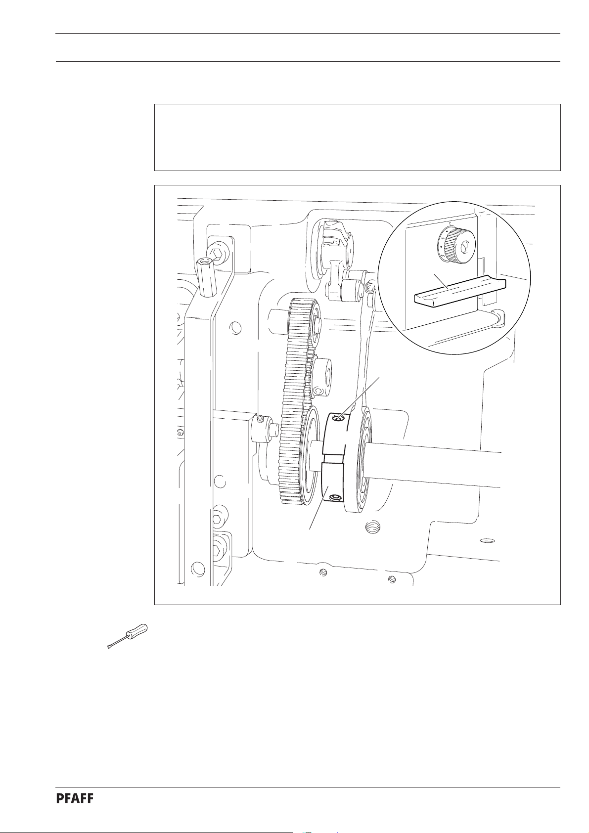
.05.12 Hook shaft bearing and toothed belt tension
13
Requirement
1. The front edge of the hook shaft 6 must be at a distance of 14.5 mm to the needle
center. At the same time, the slot in the hook shaft bearing 1 (see arrow) must be parallel to the bedplate and pointing opposite to the direction of sewing.
2. The toothed belt should be tightened in such a way that, when the gauge is pushed
onto the toothed belt, the marking in the gauge window corresponds to the marking on
the bushing.
2
14,5 mm
4
Fig. 13 - 13
5
3
1
1
13 - 14
● Align hook shaft bearing 1 (screw 2) according to requirement 1.
● Push the gauge (Part-No. 61-111 639-76) onto the toothed belt so that it is centred to the
toothed belt and touching the bearing of the sliding shaft. The gauge window must be
facing the hook.
● Eccentric 3 (screw 4) clockwise in accordance with requirement 2, taking care that the
axial position of eccentric 3 is not altered.
Page 19

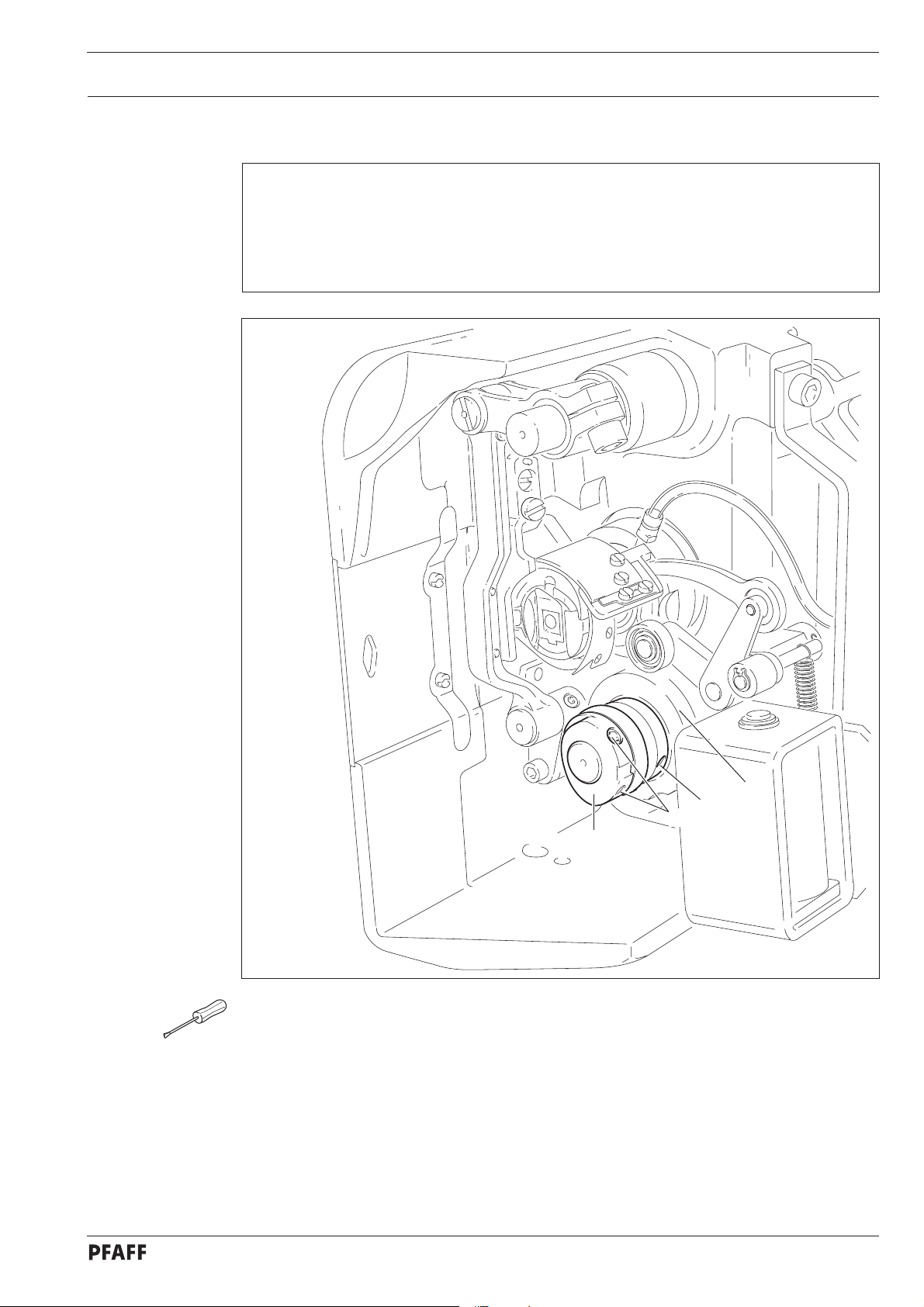
13.05.13 Hook lubrication
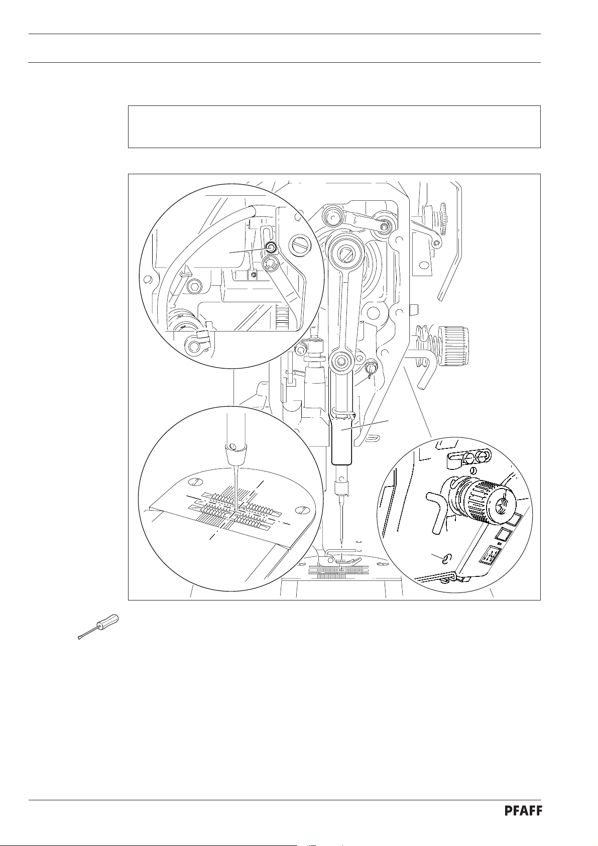
Requirement
1. The centrifugal disk 1 must be positioned 1.5 mm in front of the oil ring 3.
2. When the machine is running at full speed, after approx. 10 seconds a mark should be
made by a fine stripe of oil on the strip of paper placed over the needle plate cutout.
Adjustment
1,5 mm
3
2
1
Fig. 13 - 14
The adjustment is only necessary if the wick has been replaced.
When replacing the wick, make sure that the new wick is impregnated with oil.
● Move the centrifugal disk 1 (screw 2) according to requirement 1.
● Check requirement 2. If necessary, move centrifugal disk 1.
13 - 15
Page 20

Adjustment
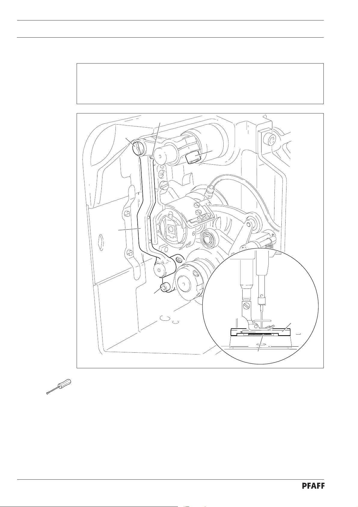
13.05.14 Needle rise, hook-to-needle clearance, needle height and bobbin case position finger
Requirement
With the needle at 1.8 mm after BDC,
1. the hook point 6 must point to the middle of the needle and be at a distance of
0.05 mm - 0.1 mm to the clearance cut of the needle, and
2. the top edge of the needle eye must be 0.8 mm below the hook point.
3. Between the projection of the bobbin case position finger 4 and the bottom of the
retaining groove there should be a distance of 0.5 mm.
0.05 - 0.1 mm
6
4
1
0.5 mm
3
13 - 16
0.8 mm
4
2
Fig. 13 - 15
● Using the adjustment pin, position the needle bar at 1.8 mm after BDC.
● Adjust the hook according to requirement 1.
● Tighten screw 1.
● Move needle bar 2 (screw 3) without turning it according to requirement 2.
● Align bobbin case position finger 4 (screw 5) according to requirement 3.
5
Page 21

.05.15 Thread check spring and slack thread regulator
13
Requirement
1. The motion of the thread check spring must be completed when the needle point
enters the material (spring stroke approx. 7 mm).
2. When the thread loop is at its largest when going around the hook, the thread check sp-
ring must have moved by approx. 1 mm.
+
Adjustment
4
-
3
1
2
7 mm
Fig. 13 - 16
● Turn thread tension 1 (screw 2) according to requirement 1.
● Turn thread tension 3 (screw 4) according to requirement 2.
Due to technical sewing reasons it may be necessary to deviate from the spring
stroke indicated above.
Move the slack thread regulator 3 (screw 4) toward the "+" (= more thread) or
toward the "-" (= less thread)
13 - 17
Page 22

Adjustment
13.05.16 Position of knee lever
Requirement
1. When the knee lever is in its resting position, the axle 5 must be parallel to the
bedplate.
2. When the presser foot is resting on the needle plate, the presser bar lifting lever 6 must
be touching the circlip 8 lightly and be at a distance of approx. 1 mm from lifting piece
7.
6
8
1 mm
7
1
5
4
2
3
13 - 18
Fig. 13 - 17
● Lower the presser foot onto the needle plate.
● Turn shaft 1 (screws 2) according to Requirement 1.
● Turn screw 3 (nut 4) according to Requirement 2.
Page 23

.05.17 Knee lever stop
13
Requirement
When the knee lever is fully actuated,
1. the presser foot must be raised approx. 9 mm (or approx. 13 mm for a large needle bar
stroke) above the needle plate, and
2. lever 3 must swing down automatically.
Adjustment
3
1
9 or 13 mm
2
Fig. 13 - 18
● Loosen nut 1 and unscrew screw 2 a few turns.
● Raise the presser foot and slide a 9 mm (for small needle bar stroke) or 13 mm (for large
needle bar stroke) thick spacer under the presser foot.
● Swing down lever 3
● Move the knee lever until it is fully actuated. The presser foot must remain on the spacer.
● Now turn screw 2 as far as it will go.
● Turn screw 2 a half turn back and tighten nut 1.
13 - 19
Page 24

Adjustment
.05.18 Bobbin winder
13
Requirement
1. With the bobbin winder on, the drive wheel 1 must engage reliably.
2. With the bobbin winder off, the friction wheel 5 must not be driven by the drive
wheel 1.
3. The bobbin winder must turn off automatically when the thread level is approx. 1 mm
from the edge of the bobbin.
5
1
2
4
Fig. 13 - 19
● Move drive wheel 1 (screws 2) in accordance with requirement 1 and 2.
● Move bolt 3 (screw 4) in accordance with requirement 3.
3
13 - 20
Page 25

.05.19 Limiting the stitch length
13
The maximum stitch length which can be selected can be limited mechanically.
Adjustment
2
4
Fig. 13 - 20
3
1
When using Version A and B part sets, the maximum adjustable stitch length
must not be larger than 3.0 or 4.5 mm (see chapter 3 Specifications)!
● Set the desired maximum stitch length with regulator disk 1.
● Move crank 2 (screws 3) down against stop 4.
13 - 21
Page 26

Adjustment
13.05.20 Stitch length adaptation
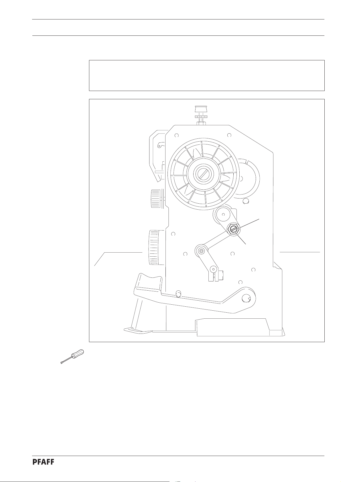
Requirement
Forward and reverse stitches should have the same length.
1
2
Fig. 13 - 20a
● Turn eccentric 1 (screw 2) according to Requirement.
13 - 22
Page 27

.05.21 Presser foot pressure
13
Requirement
The material must be fed reliably. In the process, pressure marks on the material must not
be made.
Adjustment
1
-
+
Fig. 13 - 21
● Turn screw 1 in accordance with the requirement.
13 - 23
Page 28

Adjustment
13.05.22 Modifying the needle bar stroke
The needle bar stroke is preset in the factory according to requirement. The
needle bar stroke can be modified later if specific operating conditions make it
necessary to do so.
3
1
2
-
+
13 - 24
Fig. 13 - 22
When the needle bar stroke is altered, it is absolutely necessary to readjust the
needle height! With a 36 mm needle bar stroke, the maximum speed must be
limited to 3800 spm.
● Via the hand wheel, turn crank 1 until the screws 2 can be accessed from the side
opening of the housing.
● Turn eccentric 3 (screws 2) as far as possible toward "+" (= large needle bar stroke) or
toward "-" (= small needle bar stroke).
● Adjust needle height (see chapter 13.05.02 Preadjusting the needle height and/or
chapter 13.05.14 Needle rise, hook-to-needle clearance, needle height and bobbin
case position finger).
Page 29

13.06 Adjusting the edge trimmer –731/01
13
.06.01 Zero position of the knife
Requirement
With the edge trimmer switched off, the knife should not move when the balance wheel is
turned.
Adjustment
1
2
2
1
Fig. 13 - 23
● Turn crank 1 (screw 2) according to the requirement.
13 - 25
Page 30

Adjustment
13.06.02 Cutting motion
Requirement
With the edge trimmer switched on and the needle bar at its t.d.c. on the PFAFF 1183, or
at its b.d.c. on the PFAFF 1181, the knife should be at the top of its stroke.
1
Fig. 13 - 24
● Switch on the edge trimmer and bring the needle bar to t.d.c. or b.d.c. (see requirement).
● Turn eccentric 1 (two screws 2) according to the requirement.
2
13 - 26
Page 31

13.06.03 Knife height
Requirement
When the knife is at the bottom of its stroke, the front edge of the knife blade should be
approx. 0.5 mm below the top edge of the stationary knife.
Adjustment
0.5 mm
2
1
Fig. 13 - 25
● Switch on the edge trimmer and bring the knife to the bottom of its stroke.
● Adjust knife 1 (screws 2) according to the requirement.
13 - 27
Page 32

Adjustment
13.06.04 Knife position in sewing direction
Requirement
When the needle is at its b.d.c., the centre of the knife blade should be positioned at
"needle centre".
2
1
Fig. 13 - 26
● Adjust knife bracket 1 (screw 2) according to the requirement.
13 - 28
Page 33

13.06.05 Knife position crosswise to sewing direction
Requirement
The knife should be resting on the stationary knife 3 with light pressure.
Adjustment
2
1
Fig. 13 - 27
● Adjust knife bracket 1 (screw 2) according to the requirement.
13 - 29
Page 34

Adjustment
13.07 Adjusting the thread trimming device -900/24
13.0.01 Adjusting the solenoid / preliminary adjustment of the control cam
Requirement
1. When solenoid 3 is completely extended, roller lever 4 should be at the lowest point of
the control cam.
2. When the needle bar is positioned at 1.8 mm after b.d.c. (needle rise position), roller
lever 4 should engage in the appropriate recess of the control cam.
4
5
89-026
Fig. 13 - 28
89-025
4
6
2
3
1
13 - 30
● Adjust solenoid holder 1 (screws 2) in accordance with requirement 1.
● Adjust control cam 5 (screws 6) in accordance with requirement 2.
Page 35

13.07.02 Lateral alignment of the thread catcher
Requirement
1. The tip of the thread catcher 5 must point exactly to the center of the needle.
2. The thread catcher 5 must be horizontal. It must not graze anything when it is operating.
Adjustment
5
2
1
6
6
3
5
Fig. 13 - 29
● Remove knife 1 (screw 2).
● Move needle bar to its BDC.
● Loosen stop 3 (screws 4).
● Position thread catcher 5 (screw 6) manually in front of the needle.
● Align thread catcher 5 (screws 7) according to the requirements.
For further adjustments, leave knife 1 removed and stop 3 loosened.
13 - 31
Page 36

Adjustment
.07.03 Knife position
13
Requirement
1. There must be a distance of 4 mm between the cutting edge of the knife and the
needle.
2. The right edge of the knife 1 must not extend beyond the right edge of the thread
catcher (see arrow).
3
13 - 32
4 mm
1
2
Fig. 13 - 30
● Bring the needle bar to BDC.
● Slide knife 1 under the locking tab and align according to requirement 1.
● Tighten screw 2 lightly.
● Adjust thread catcher carrier 3 by hand until the wedge point in the thread catcher is
positioned just in front of the cutting edge of the knife.
● Align knife 1 according to requirement 2 and tighten screw 2.
1
Page 37

13.07.04 Front point of reversal of the thread catcher
89-025
Requirement
At the front point of reversal of thread catcher 4, the tip of the thread catcher cutout
should be 1 mm in front of the bobbin case position finger 5.
Adjustment
1
Fig. 13 - 31
1
2
3
4
1 mm
5
● Position roller lever 1 at the lowest point of the control cam.
● Adjust bush 2 (screws 3) according to the requirement.
13 - 33
Page 38

Adjustment
13.07.05 Manual trimming check
Requirement
Two threads must be cut perfectly both left and right in the cutout of thread catcher 1.
2
1
5
3
4
1
Fig. 13 - 32
● Move thread catcher 1 by hand to its front point of reversal.
● Double the thread and insert into catcher cutout.
● Carry out trimming operation manually.
● If the threads are not cut according to the requirement, align thread catcher 1
(screws 2) with knife 3 accordingly.
● Move stop 4 against thread catcher 1 and tighten screws 5.
● Check chapter 13.07.02 Lateral alignment of the thread catcher, and readjust if
necessary.
13 - 34
Page 39

.07.06 Needle thread tension release
13
Requirement
1. The magnet lift should be 1.5 mm.
2. When the magnet 5 is operated by hand, there should be a distance of at least 0.5 mm
between the tension discs 6.
5
Adjustment
0.5 mm
6
Fig. 13 - 33
4
3
2
1
● Adjust disc 1 (nuts 2) according to the requirement.
● Adjust screw 3 (nut 4) according to the requirement.
13 - 35
Page 40

Adjustment
13.07.07 Readjusting the control cam
Requirement
When the take-up lever is in its t.d.c., control cam 1 should have moved thread catcher 3.
3
1
Fig. 13 - 34
● Adjust control cam 1 (screws 2) according to the requirement.
2
13 - 36
Page 41

08 Adjusting the thread wiper -909/04
13.
13.08.01 Thread wiper movement
Requirement
1. The thread wiper 5 must not strike against anything when it is moving.
2. When the take-up lever is at TDC, the thread wiper 5 is to move under the needle point
and clear it by approx. 1 mm when the engaging solenoid 2 is operated.
Adjustment
1
I
2
3
5
4
1 mm
5
Fig. 13 - 35
● Bring the take-up lever to TDC.
● Loosen screws 1.
● Push thread wiper 2 parallel to the bedplate to the very top and tighten screws 1 slightly.
● Turn bracket 3 (screw 4) according to requirement 1.
● Move thread wiper 2 parallel to the bedplate according to requirement 2.
● Tighten screws 1.
13 - 37
Page 42

Adjustment
13.08.02 Thread wiper position
Requirement
Seen from the direction of sewing
1. The point of the thread wiper 5 must be approx. 1 - 1.5 mm to the right of the needle,
and
2. The thread wiper 5 must be approx. 2 mm in front of the needle in its foremost
position.
5
Fig. 13 - 36
3
1 - 1.5 mm
4
2
1
5
2 mm
13 - 38
● Slide bracket 1 (screw 2), without turning it, on the shaft according to requirement 1.
● Turn rod 3 (nut 4) according to requirement 2.
Page 43

13.09 Adjusting the automatic presser foot lift -910/06
Requirement
When the automatic presser foot lift is operated, the clearance between the presser foot
and the needle plate must be 9 mm for a small needle bar stroke and 13 mm for a large
needle bar stroke.
1
Adjustment
Fig. 13 - 37
2
9 or 13 mm
● Move magnet 1 (screw 2) according to the requirement.
13 - 39
Page 44

Adjustment
13.10 Adjusting the back-tacking mechanism –911/37
Regel
When the longest stitch length is set, the reverse-feed control switch 3 operated and the
plunger extended, lever 1 should not touch the bed-plate.
1
2
3
13 - 40
Fig. 13 - 38
● Adjust lever 1 (screw 2) according to the requirement.
Page 45

13.11 Parameter settings
13.11.01 Selecting the user level
● Switch on the machine.
3333
ABCD
Adjustment
2 x
● Press the TE/Speed key twice to call up the input mode.
TE
101 on
A
● By pressing the corresponding +/- key select the parameter group "798".
TE
798 0
A
● By pressing the corresponding +/- key select the desired user level:
"0" = operator level A
"1" = technician level B
"11" = service level C
The selected user level is displayed on the screen. (see arrow)
13 - 41
Page 46

Adjustment
.11.02 Example of a parameter input
13
● Switch on the machine.
2 x
● Press the TE/Speed key twice to select the input mode.
TE
101 on
A
● By pressing the corresponding plus/minus key select parameter "798" and the desired
user level, see Chapter 13.11.01 Selecting the user level.
TE
798 1
B
12
● Select parameter "607" by pressing the corresponding +/- key.
TE
607 4200
B
● Select the required value for the maximum speed by pressing the corresponding +/- key.
● By pressing the TE/Speed key the selected value is taken over and the machine switches
to the sewing mode.
13 - 42
Page 47

.11.03 Liste der Parameter
13
Gruppe
1 101 Control panel beep tone A, B, C on
6 605 Speed display B, C off
7 700 Needle postion 0
Parameter
607 Speed max. B, C 300 - 6000 4000
609 Cutting speed B, C 60 - 500 180
660 Bobbin thread control A,B,C 0 - 2 0
Adjustment
Bedeutung
0 = off
1 = thread monitor
2 = reverse counter
(needle reference position) B,C 0 – 255
Nutzer-
ebene
Einstell-
bereich
Einstell-
wert
702 Needle position 1 (needle lowered) B,C 0 – 255 90
703 Needle position 2 (take-up lever raised) B, C 0 - 255 236
705 Needle position 5 (end of cutting signal 1) B, C 0 - 255 200
706 Needle position 6 (start of cutting signal 2) B, C 0 - 255 136
707 Needle position 9 (start thread tension
release) B,C 0 - 255 164
797 Hardwaretest B, C off
798 User level A,B,C 0,1,11 0
0 = User level
1 = Technician level
11 = Service level
799 Selected machine class C 1 - 3 1
8 800 Rotating direction of the motor C 0 - 1 0
Further parameters are listed in the Motor Instruction Manual.
13 - 43
Page 48

Adjustment
13.11.04 Reset / Cold start
After selecting the reset menu, by pressing the corresponding key it is possible to delete
seam parameters, delete seam programs and to carry out a cold start.
A
● Press and hold "+" on keys A and D and switch on the machine, see Chapter 7.01 Main
switch.
1_ 2 _ _ _ 3 _
AB D
A
B
Resetting the seam parameters
● Press "+"on key "A".
All parameters are deleted, the display "—rE—" appears for a short time on the screen.
Resetting the seam programs
● Press "+"on key "B".
All seam programs are deleted, the display "—rE—nA" appears for a short time on the
screen.
D
13 - 44
D
Cold start
● Press "+" on key "D".
With the exception of the value for the machine class, the values of the machine control
unit are set back to their basic values, the display "—COLd—" appears for a short time on
the screen.
After the cold start all programmed values are set back to their status at the
time of delivery. For this reason after a cold start it is necessary to re-enter first
the parameter "799" and then the parameter "700".
Page 49

13.12 Internet update of the machine software
The machine software can be updated with PFAFF flash programming. For this purpose the
PFP boot program and the appropriate control software for the machine type must be
installed on a PC. To transfer the data to the machine, the PC and the machine control unit
must be connected with an appropriate null modem cable (part no. 91-291 998-91).
The PFP boot program and the control software of the machine type can be
downloaded from the PFAFF-homepage using the following path:
www.pfaff-industrial.com/de/service/download/steuerungssoftware.html
To update the machine software carry out the following steps:
While the machine software is being updated, no setting up, maintenance or
adjustment work may be carried out on the machine!
● Switch off the machine.
● Connect the PC (serial interface or appropriate USB-adapter) and the machine control unit
(RS232).
● Switch on the PC and start the PFP boot program.
● Select the machine type.
● Press the "programming" button.
● An extra program (quick loader) is started.
● Switch on the machine within 60 seconds.
● The software update is carried out, the update progress is shown on the bar display.
● When the update has been completed, the message "software update successfully
completed" appears.
Adjustment
If this message does not appear, the entire procedure must be repeated!
The machine is not safe for operation until the programming has been
completed successfully and without faults.
● Switch off the machine and end the quick loader and PFP boot program.
● End the connection between the PC and the machine control unit.
● Switch on the machine.
● A plausibility control is carried out and, if necessary, a cold start.
More information and assistance is at your disposal in the file "PFPHILFE.TXT",
which can be called up from the PFP boot program by pressing the "help"
button.
13 - 45
Page 50

Adjustment
13.13 Explanation of the error signals
Signal Description
E001 Pedal not in neutral position
E009 Start inhibitor during standstill
E010 Incorrect machine class
E062 Short circuit 24V
E063 Overload mains supply circuit
E064 Network monitoring
E065 Extint low in operation
E066 Short circuit
E067 Network off
E068 Extint low in operation
E069 No increments
E070 Motor blocking
E071 No incremental connector
E074 External transmitter for synchronisation marker missing
E088 RAM defective
E092 Start inhibitor when motor running
E173 Start error
13 - 46
Page 51

14 Circuit diagrams
Circuit diagram reference list
A1 Controller Quick P40 ED
A2 Keyboard on machine head
A3 Sewing head recognition system
A4 Control panel S1
H1 Sewing lamp
M1 Sewing motor
Q1 Main switch
S1 Pedal speed control unit
Circuit diagrams
A2/S1 Bartack key on
A2/S2 Needle position change key
A2/S3 Bartack suppression key
S4 Suction OFF key
S6 Start inhibitor key
X1 Motor
X2 Increment transmitter
X3 Speed control unit
X4 Control panel S1
X5 Outputs-inputs
X6 Photoelectric barrier (optional)
X7 Bobbin thread monitor (optional)
Y1 Motor running signal or suction
Y2 -900/.. Thread trimmer
Y3 -909/.. Thread wiper
Y4 -910/.. Automatic presser foot lift
Y5 -911.. Backtacking mechanism
Y8 Thread tension release
14 - 1
Page 52

Circuit diagrams
Version 05.06.03
91-791 229-95
Page 1
14 - 2
Page 53

91-791 229-95
Page 2 Version 05.06.03
Circuit diagrams
14 - 3
Page 54

PFAFF Industrie Maschinen AG
Postfach 3020
D-67653 Kaiserslautern
Königstr. 154
D-67655 Kaiserslautern
Telefon: (0631) 200-0
Telefax: (0631) 17202
E-Mail: info@pfaff-industrial.com
 Loading...