

Page 1
Handbook
PARTNER Tepee
Page 2
On-line handbook
Select one of the following means of access to view your
handbook on-line...
Find your handbook on the PeugeOt website, under
"MyPeugeOt".
this personal and customisable space allows you to establish
direct and special contact with CItROËN.
Referring to the handbook on-line also gives you access to the
latest information available, easily identified by the bookmark,
associated with this symbol:
Scan this code for direct access to your handbook.
If the "MyPeugeOt" function is not available on the PeugeOt
public website for your country, you can find your handbook at the
following address:
http://public.servicebox.peugeot.com/ddb/
Select:
the language,
the vehicle, its body style,
the print edition of your handbook appropriate for the date of registration of
your vehicle.
Page 3
Welcome
this new vehicle has been designed to satisfy all
your requirements in terms of practicality, comfort,
safety and aesthetics. In order to get the most out of
your vehicle, we suggest that you take a tour, from
the cab to the load space, with the "Handbook" in
front of you. the handbook presents the operation of
the equipment available on board in detail.
PEUGEOT thanks you for your condence and
wishes you very happy motoring.
Page 4

Contents
OVERVIEW
1.
2
4-14
exterior 5
Interior 6
left hand drive 6
right hand drive 7
Instruments and controls 8
left hand drive 8
right hand drive 10
technical data -
Maintenance 12
the "Visual Search " (visual
index) section assists
you in nding the controls
and functions and their
associated page numbers
on the schematic outlines of
the vehicle.
Instruments and controls
left hand drive 13
right hand drive 14
ECO-DRIVIng
2.
15-17
environment 15
Eco-driving 16
3.
READY TO SET OFF
18-54
Key 18
Alarm 20
Doors 21
tailgate 23
Rear roof ap 26
Central
locking 27
Instrument panel 28
Date and time 29
Warning lamps 32
Fuel gauge 40
Coolant 40
Under-ination
detection 41
Service indicator 43
Lighting dimmer 44
Steering wheel
adjustment 45
Manual gearbox 45
Gear shift indicator 46
6-speed electronic
gearbox 47
Stop & Start 49
Starting and stopping 52
Hill start assist 53
Driving
recommendations 54
4.
EASE OF USE and
55-110
COMFORT
Lighting 55
Wipers 58
Trip computer 60
Cruise control 61
Speed limiter 64
Heating / Air conditioning
manual 67
digital 69
Demisting and
defrosting 72
Front seats 74
Rear bench seat 76
Rear seats
(5 seat version) 79
Rear seats
(7 seat version) 82
Modularity 89
Front ttings 91
Zenith roof 95
Roof bars 100
Courtesy lamps 101
Load space cover
(5 seat version) 102
Load space cover
(7 seat version) 106
Mirrors 108
electric windows 110
SAFETY
5.
111-144
Hazard warning lamps 111
Horn 111
Parking brake 111
Parking sensors 112
Reversing camera 114
Anti-lock braking
system (ABS) 115
eBA 115
ASR and DSC 116
grip control 117
Active City Brake 119
Seat belts 123
Airbags 126
Carrying children 130
Deactivating the
passenger's front
airbag 133
Recommended seats 136
Installation 138
ISOFIX mountings 140
Recommended ISOFIX
seat 141
ISOFIX locations 142
Child lock 144
Page 5

ACCESSORIES
6.
145-150
towing a trailer 145
towbar with detachable
swan neck towball 147
Other accessories 149
8.
QUICK HELP
168-191
Battery 168
Puncture repair kit 170
Changing a wheel 171
Removable snow
screen 177
Snow chains 178
Changing a bulb 179
a fuse 185
a wiper blade 189
Being towed 190
Precautions 191
10.
TECHnOLOgY on
201-281
BOARD
7-inch touch
screen 201
PeugeOt Connect
Sound (RD5) 263
the "technology on board"
section presents the new
audio/navigation systems.
Contents
3
CHECKS
7.
151-167
Opening the bonnet 152
Petrol engine 153
Diesel engine 154
Levels 155
Checks 157
Fuel 159
Fuel cut-off 160
Diesel priming pump 160
BlueHDi and AdBlue
additive 161
®
9.
TECHnICAL
192-200
DATA
Dimensions 192
Engines 196
Weights 196
Identication
markings 200
PeugeOt Connect is
the name given to all of the
new equipment of the radio/
navigation range.
corresponds to
a left hand drive
vehicle.
corresponds to
a right hand drive
vehicle.
CONTENTS
Page 6
InTRODUCTIOn
4
the equipment presented may be
standard, an option or not available,
depending on the model and can vary
from one country to another or not be
available in all countries.
We draw your attention to the
following point:
The tting of electrical equipment
or accessories which are not
recommended by PeugeOt may
result in a failure of your vehicle's
electronic system. Contact a
PeugeOt dealer to be shown
the recommended equipment and
accessories.
For any work on your vehicle, use
a qualied workshop that has the
technical information, competence
and equipment required, which a
PeugeOt dealer is able to provide.
Within each section, symbols draw
your attention to specic information:
directs you to the section and
part which contains detailed
information concerning a function,
indicates important information
relating to use of the equipment,
alerts you to the safety of
individuals and on-board
equipment.
Page 7
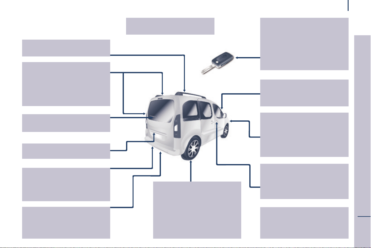
Location
ExTERIOR
Accessories 149-150
Zenith roof 95-96, 99
Roof bars 100
Rear lamps, direction
indicators 55-56
3rd brake lamp 184
Changing rear
bulbs 179-180, 183-184
Doors, tailgate 23-25
Rear roof ap 26
emergency control 23
Number plate lamps 184
Spare wheel, jack, changing a
wheel, tools 171-176
temporary puncture repair kit 170
Ination, pressures 200
towing, lifting 190
towbar, swan neck
towball 145-148
Parking sesnsors 112-113
Reversing camera 114
Dimensions 192-195
Brakes, pads 111, 155, 157
emergency braking 115
ABS, eBFD 115
ASR, DSC 116
"grip control" 117-118
Active City Brake 119-122
tyres, pressures 200
Snow chains 178
Tyre under-ination
detection 41-42
Remote control 18-19
Changing the battery,
reinitialisation 19
Key 18
Starting 52
Hill start assist 53
Central locking / unlocking 18, 27
Wiper blades 189
Door mirrors 108
Side repeaters 182
Active City Brake 119-122
Front lamps, foglamps, direction
indicators 55-57, 179-182
Headlamp beam height
adjustment 57
Changing front bulbs 179-182
Headlamp wash 59, 156
Snow cover 177
Front doors 21
Sliding side doors 22-23
Key 18
Opening the bonnet 152
Child lock 144
Filler cap, fuel tank 159-160
Fuel cut-off, Diesel priming 160
®
AdBlue
additive,
opping up 38-39, 161-167
5
OVERVIEW
1
Page 8
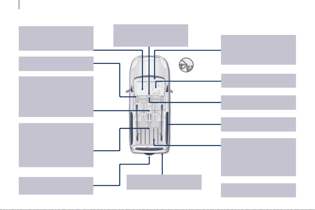
Location
InTERIOR
6
Front seats, adjustments,
head restraint 74-75
Seat belts 105, 123-125
Opening the bonnet 152
Rear bench seat 76-78
Rear seats
(5-seat version) 79-81, 89
Seat conguration,
benches 89-90
Rear courtesy lamp 101
Changing courtesy lamp bulbs 182
Rear ttings 94
- oor boxes,
- aircraft style table,
- side blinds,
Zenith roof 95-96
Scented air freshener 97-98
Load space cover (5-seat version
Load space cover
(7-seat version) 106-107
) 102
Rear view mirror 109
Front courtesy lamp 101
Changing courtesy lamp bulbs 182
Front, lateral,
curtain airbags 126-129
Deactivating the passenger's
front airbag 129, 133
Battery, charging, starting 168
Child seats 130-139, 143
ISOFIX mountings, seats 140-142
Parking brake, handbrake 111
Rear windows 109
Rear seats
(7-seat version) 82-88, 90
Fittings (7-seat version) 104-105
- cup holder,
- 12 V socket,
- stowing rings,
- storage ap.
Spare wheel, jack,
changing a wheel,
tools 171-176
towing, llifting 190
Towable loads 196-199
Accessories 149-150
Page 9
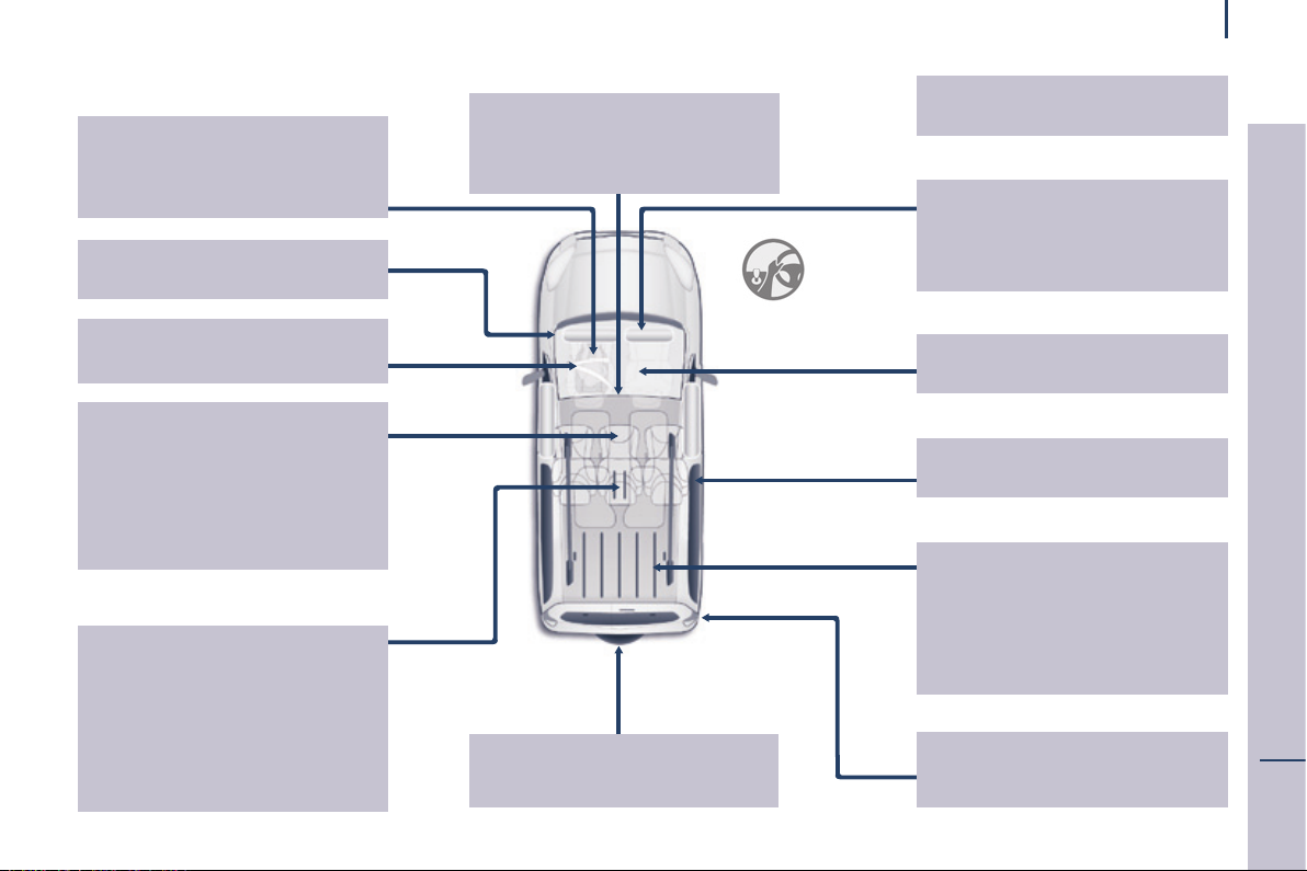
InTERIOR
Front seats, adjustments,
head restraint 74-75
Seat belts 105, 123-125
Opening the bonnet 152
Child seats 130-139, 143
ISOFIX mountings, seat 140-142
Rear bench seat 76-78
Rear seats
(5-seat version) 79-81, 89
Seat conguration, benches 89-90
Rear courtesy lamp 101
Changing courtesy
lamp bulbs 182
Rear ttings 94
- oor boxes,
- aircraft style table,
- side blinds,
Zenith roof 95-96
Scented air freshener 97-98
Load space cover (5-seat version)
Load space cover
(7-seat version) 106-107
102
Rear view mirror 109
Front courtesy lamp 101
Changing courtesy
lamp bulbs 182
Spare wheel, jack,
changing a wheel,
tools 171-176
Location
Accessories 149-150
Front, lateral, curtain
airbags 126-129
Deactivating the passenger's
front airbag 129, 133
Battery, charging, starting 168
Parking brake, handbrake 111
Rear windows 109
Rear seats
(7-seat version) 82-88, 90
Fittings (7-seat version) 104-105
- cup holder,
- 12 V socket,
- stowing rings,
- storage ap.
towing, llifting 190
Towable loads 196-199
7
OVERVIEW
1
Page 10
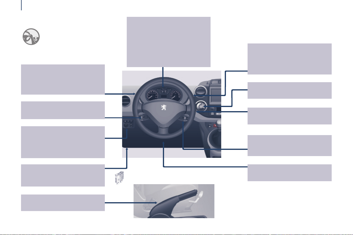
Location
InSTRUMEnTS AnD COnTROLS
8
Lighting controls 55-57
Foglamps 56
LED daytime running lamps 56
Automatic illumination of
headlamps 56-57
Cruise control 61-63
Speed limiter 64-66
ESC 116
Parking sensors 112-113
electric mirrors 108
Headlamp beam height adjustment
Stop & Start 49-51
Dashboard, passenger
compartment fuses 185-187
Opening the bonnet 152
57
Instrument panels, screens,
dials 28-29
Setting the time in the instrument
panel 29
Warning lamps, indicator
lamps 32-39
Indicators, fuel gauge 40, 43-44
Lighting dimmer 44
Gear shift indicator 46
Wiper controls 58-59
Automatic rain sensitive wipers 58
Screenwash / headlamp
wash 59, 156
Trip computer 60
electronic gearbox 47-48
Ignition switch 52
Steering mounted controls:
- touch screen 204
-
PeugeOt Connect Sound (RD5)
Steering wheel adjustment 45
Horn 111
265
Parking brake 111
Page 11
Rear view mirror 109
Child surveillance mirror 109
Screens, menus 28, 205, 266
Setting the time in
the screen 30-31
"grip control" 117-118
Location
Courtesy lamps 101, 182
Touch screen 201-262
PeugeOt Connect Sound (RD5)
Reversing camera 114
Deactivating the passenger's
front airbag 129, 133
Heating, ventilation
- heating 67-68, 71
- air conditioning A/C 67-68, 71
Digital air conditioning 69-70, 71
Demisting/defrosting 72-73
263-281
9
Controls
- central locking 27
- electric child lock 144
- electric windows 110
- hazard warning lamps 111
Manual gearbox 45
Front ttings 91-93
- storage compartment.
- glove box,
- bottle holder,
- bag holder,
- centre console,
- overhead storage,
- sun visor,
- storage drawers,
OVERVIEW
1
Page 12
Location
InSTRUMEnTS AnD COnTROLS
10
Lighting controls 55-57
Foglamps 56
LED daytime running lamps 56
Automatic illumination of
headlamps 56-57
electronic gearbox 47-48
Cruise control 61-63
Speed limiter 64-66
Steering wheel adjustment 45
Horn 111
Instrument panels, screens,
dials 28-29
Setting the time in the instrument
panel 29
Warning lamps,
indicator lamps 32-39
Indicators, fuel gauge 40, 43-44
Lighting dimmer 44
Gear shift indicator 46
Wiper controls 58-59
Automatic rain sensitive wipers 58
Screenwash / headlamp
wash 59, 156
Trip computer 60
Deactivating the passenger's
front airbag 129, 133
Ignition switch 52
ESC 116
Parking sensors 112-113
electric mirrors 108
Headlamp beam height adjustment
Stop & Start 49-51
Steering mounted controls:
- touch screen 204
- PeugeOt Connect
Sound (RD5) 265
57
Parking brake 111
Page 13
Rear view mirror 109
Child surveillance mirror 109
Location
Courtesy lamps 101, 182
Screens, menus 28, 205, 266
Setting the time in
the screen 30-31
Touch screen 201-262
PeugeOt Connect Sound (RD5)
Reversing camera 114
263-281
11
Front ttings 91-93
- storage compartment.
- glove box,
- bottle holder,
- bag holder,
- centre console,
- overhead storage,
- sun visor,
- storage drawers,
Dashboard, passenger
compartment fuses 185-187
Opening the bonnet 152
Manual gearbox 45
"grip control" 117-118
Heating, ventilation
- heating 67-68, 71
- air conditioning A/C 67-68, 71
Digital air conditioning 69-70, 71
Demisting/defrosting 72-73
Controls
- central locking 27
- electric child lock 144
- electric windows 110
- hazard warning lamps 111
OVERVIEW
1
Page 14
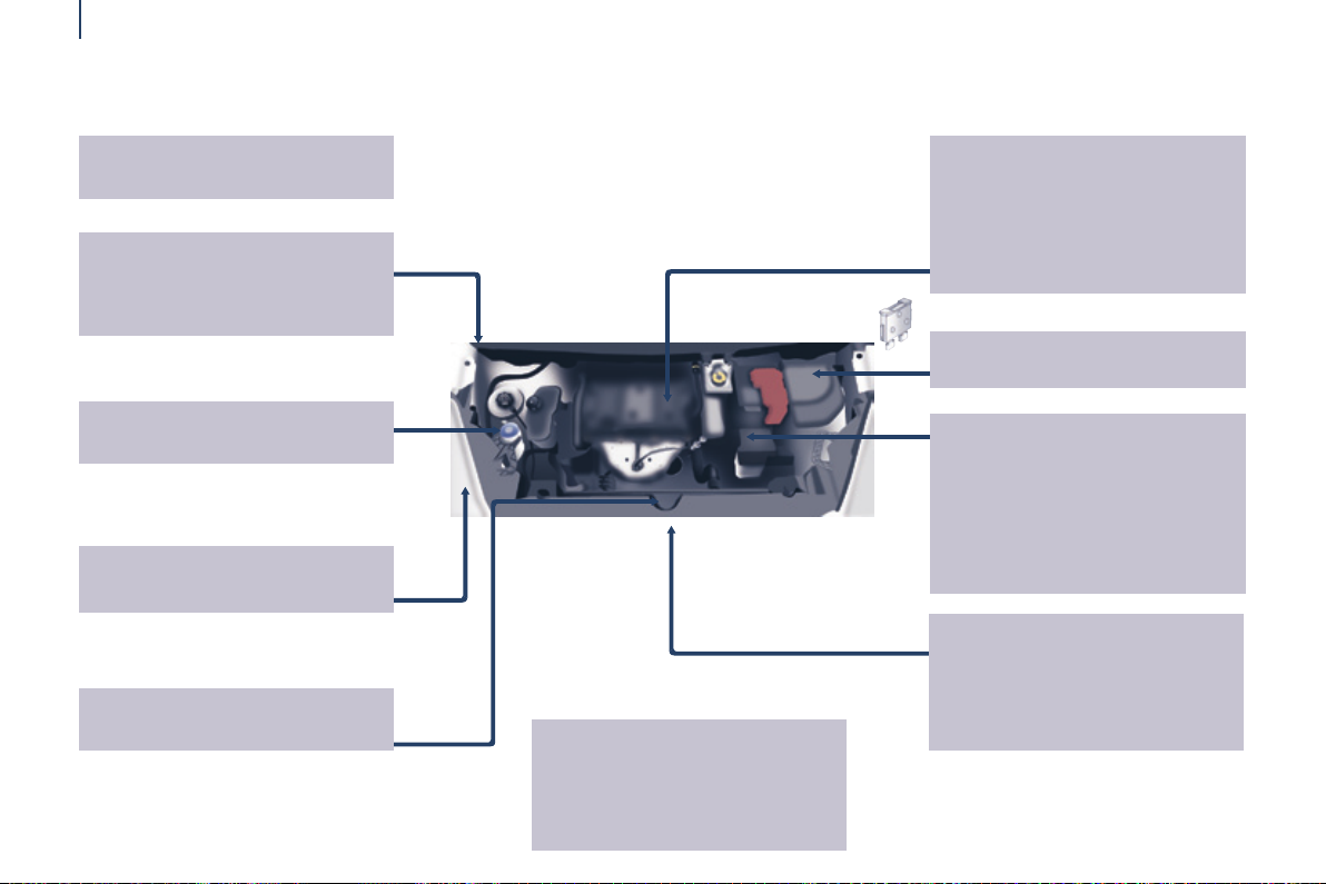
Location
TECHnICAL DATA - MAInTEnAnCE
12
Warning lamps 32-39
Identication markings, serial
number, paint code, tyres 200
Windscreen / headlamp wash,
levels 156
Changing bulbs, lighting 179-184
Opening the bonnet, stay 152
Dimensions 192-195
Petrol engines / Weights 196-197
Diesel engines /
Weights 196, 198-199
Levels 155-156
- engine oil dipstick,
- brake uid,
- coolant.
- power steering uid,
- Diesel additive,
Bleeding water, Diesel lter 158
engine fuses 185, 188
Checks 157-158
- battery,
- brake pads,
- brake drums, discs.
- parking brake,
-
carbon/passenger compartment lter,
- oil lter,
- particle lter,
- gearbox,
under the bonnet
- Diesel 154
- petrol 153
Fuel cut-off, Diesel priming 160
®
AdBlue
additive 161-167
Page 15
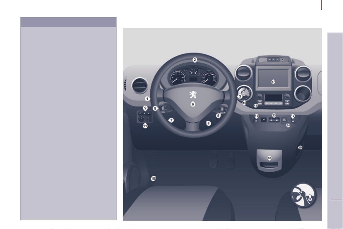
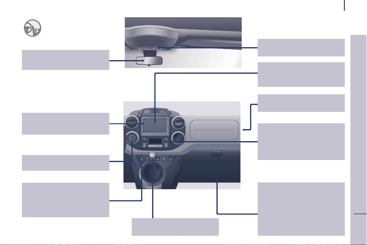
Presentation
InSTRUMEnTS AnD COnTROLS
1. Lighting and direction indicator stalk.
2. Instrument panel with screen.
3. Wipers, screenwash, trip computer
control stalk.
4. Ignition.
5. Audio system controls.
6. Driver's front airbag, horn.
7. Steering wheel height and reach
adjustment.
8. Cruise control, speed limiter controls.
9. Switch panel, parking sensors,
headlamp beam adjustment, eSC,
Stop & Start.
10. Bonnet release.
11. electric door mirror adjustment.
12. electric window switches.
13. Switch panel: hazard warning lamps,
central locking, child lock.
14. Cigarette lighter.
15. Heating-ventilation controls.
16. electronic gearbox controls or grip
control button.
17. touch screen.
18. Prise uSB (avec boîte manuelle
pilotée).
19. Prise uSB (avec boîte de vitesses
manuelle).
13
OVERVIEW
1
Page 16
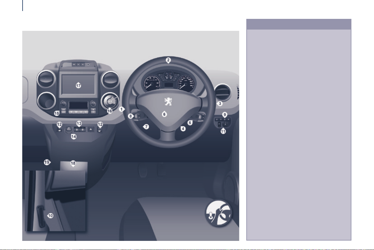
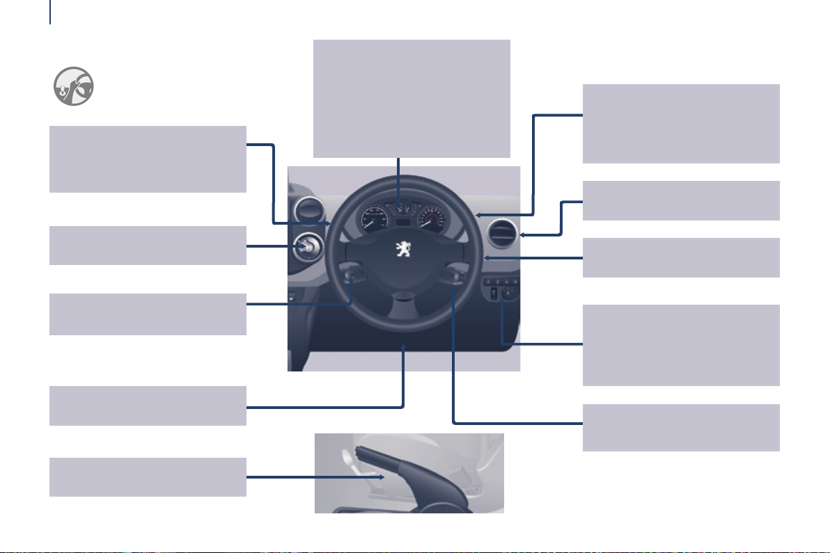
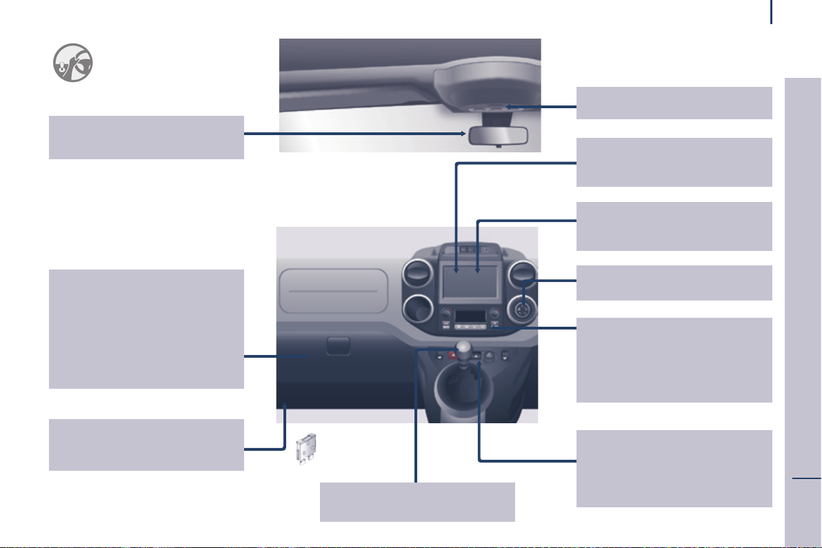
Presentation
14
InSTRUMEnTS AnD COnTROLS
1. Lighting and direction indicator
control stalk.
2. Instrument panel with screen.
3. Wiper, screenwash, trip computer
control stalk.
4. Ignition switch.
5. Audio system controls.
6. Driver's front airbag, horn.
7. Steering wheel height and reach
adjustment.
8. Cruise control, speed limiter controls.
9. Switch panel, parking sensors,
headlamp beam adjustment, eSC,
Stop & Start, alarm.
10. Bonnet release lever.
11. electric door mirror controls.
12. electric window switches.
13. Switch panel: hazard warning, central
locking, child lock.
14. Cigarette lighter.
15. Heating-ventilation controls.
16. electronic gearbox controls or grip
control button.
17. touch screen.
18. uSB port (with electronic gearbox).
19. uSB port (with manual gearbox).
Page 17
Environment
With you, PeugeOt acts to protect
the environment.
We invite you to visit the
www.peugeot.co.uk website.
As the driver, you also can contribute
to protecting the environment by
following certain rules:
- adopt a preventive style of driving,
without frequent and harsh
acceleration,
- observe the service intervals;
we recommend that services are
carried out by a PeugeOt dealer,
authorised to collect used batteries
and uids,
- in order to preserve the reliability
of the engine and emission control
systems, do not use engine oil
additives.
Motoring & the Environment
15
Refer to information on eco-driving
at the end of this section.
ECO-DRIVING
2
Page 18

Motoring & Environment
Eco-driving
16
eco-driving is a range of everyday practices that allow the motorist to optimise their fuel consumption and CO
emissions.
2
Optimise the use of your gearbox
With a manual gearbox, move off gently and change up
without waiting. During acceleration change up early.
With an automatic or electronic gearbox, give preference
to automatic mode and avoid pressing the accelerator
pedal heavily or suddenly.
the gear shift indicator invites you engage the most
suitable gear: as soon as the indication is displayed in the
instrument panel, follow it straight away.
For vehicles tted with an electronic or automatic gearbox,
this indicator appears only in manual mode.
Drive smoothly
Maintain a safe distance between vehicles, use engine
braking rather than the brake pedal, and press the
accelerator progressively. these practices contribute
towards a reduction in fuel consumption and CO
emissions and also helps reduce the background trafc
noise.
If your vehicle has cruise control, make use of the system
at speeds above 25 mph (40 km/h) when the trafc is
owing well.
2
Control the use of your electrical equipment
Before moving off, if the passenger compartment is too
warm, ventilate it by opening the windows and air vents
before using the air conditioning.
Above 30 mph (50 km/h), close the windows and leave the
air vents open.
Remember to make use of equipment that can help keep
the temperature in the passenger compartment down
(sunroof and window blinds...).
Switch off the air conditioning, unless it has automatic
regulation, as soon as the desired temperature is attained.
Switch off the demisting and defrosting controls, if not
automatic.
Switch off the heated seat as soon as possible.
Switch off the headlamps and front foglamps when the
level of light does not require their use.
Avoid running the engine before moving off, particularly in
winter; your vehicle will warm up much faster while driving.
As a passenger, if you avoid connecting your multimedia
devices (lm, music, video game...), you will contribute
towards limiting the consumption of electrical energy, and
so of fuel.
Disconnect your portable devices before leaving the
vehicle.
Page 19

Motoring & the Environment
17
Limit the causes of excess consumption
Spread loads throughout the vehicle; place the heaviest
items in the bottom of the boot, as close as possible to the
rear seats.
Limit the loads carried in the vehicle and reduce wind
resistance (roof bars, roof rack, bicycle carrier, trailer...).
use a roof box in preference.
Remove roof bars and roof racks after use.
At the end of winter, remove snow tyres and ret your
summer tyres.
Observe the recommendations on maintenance
Check the tyre pressures regularly, when cold, referring to
the label in the door aperture, driver's side.
Carry out this check in particular:
- before a long journey,
- at each change of season,
- after a long period out of use.
Don't forget the spare wheel and the tyres on any trailer or
caravan.
Have your vehicle serviced regularly (engine oil, oil
lter, air lter, passenger compartment lter...) and
observe the schedule of operations recommended in the
manufacturer's service schedule.
With a BlueHDi Diesel engine, if the SCR system is
faulty your vehicle becomes polluting; go to a PeugeOt
dealer or a qualied workshop without delay to have the
emissions of nitrous oxides brought back to the legal level.
When refuelling, do not continue after the third cut-off of
the nozzle to avoid any overow.
At the wheel of your new vehicle, it is only after the rst
1 800 miles (3 000 kilometres) that you will see the fuel
consumption settle down to a consistent average.
ECO-DRIVING
2
Page 20
Access
18
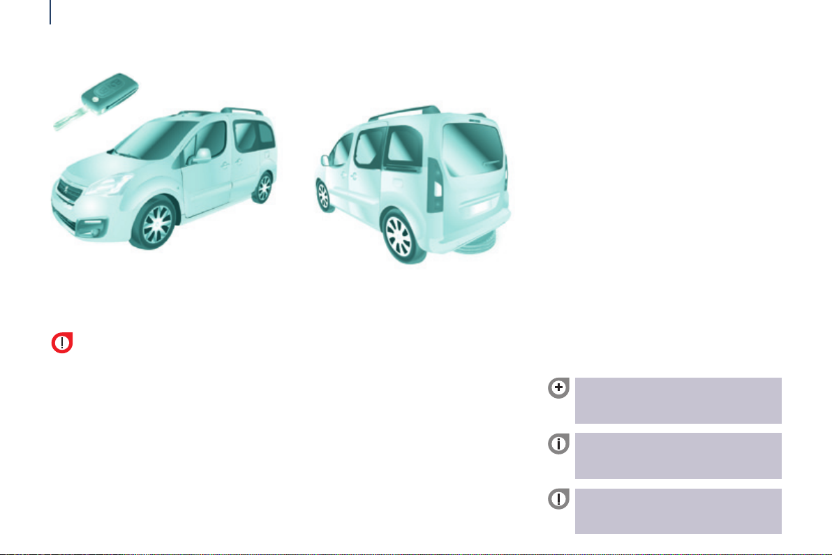
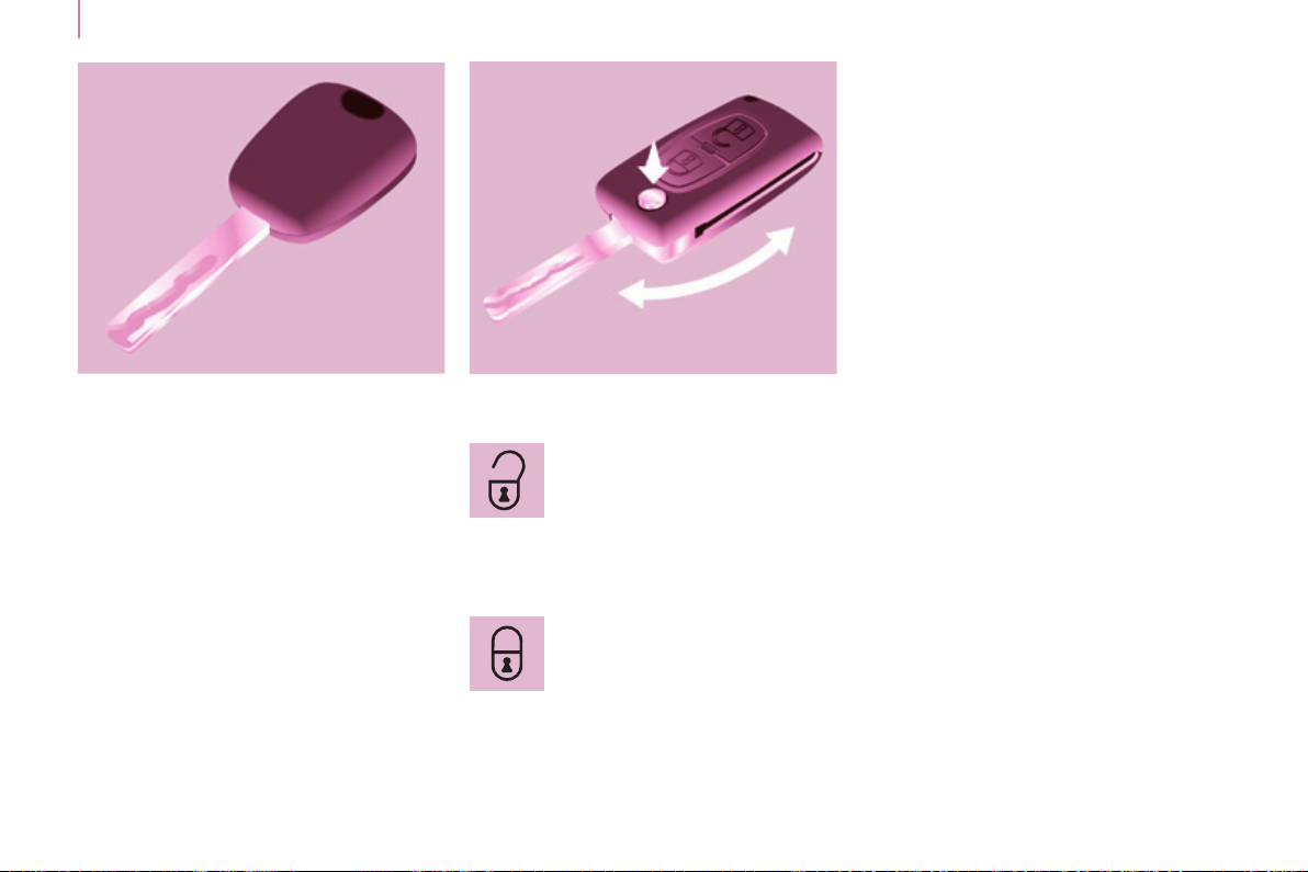
KEY REMOTE COnTROL
this locks and unlocks the vehicle's
doors, opens and closes the fuel ller
cap, as well as starting and stopping
the engine.
Unlocking
Press this button to unlock all
of your vehicle's doors.
The direction indicators ash twice.
Locking
Press this button to lock all of
your vehicle's doors.
The direction indicators ash once.
If one of the doors is open or is not
closed correctly, the central locking will
not work.
Deadlocking
A second press on the closed
padlock on the remote control within
ve seconds after locking changes the
locking to deadlocking.
This is conrmed by xed lighting
of the direction indicators for
approximately two seconds.
Deadlocking renders the exterior
and interior door opening handles
inoperative: do not leave anyone inside
the vehicle when it is deadlocked.
If deadlocking is activated from inside
the vehicle using the remote control, it
will change to normal locking when the
vehicle is started.
Page 21
Unfolding / folding
Access
If you do not press the button,
you may damage the key's
folding mechanism.
good practice
take care not to allow the remote
control to come into contact with
grease, dust, rain or a damp
environment.
A heavy object attached to the key
(key ring, ...) weighing on the shaft
of the key in the switch, may cause a
malfunction.
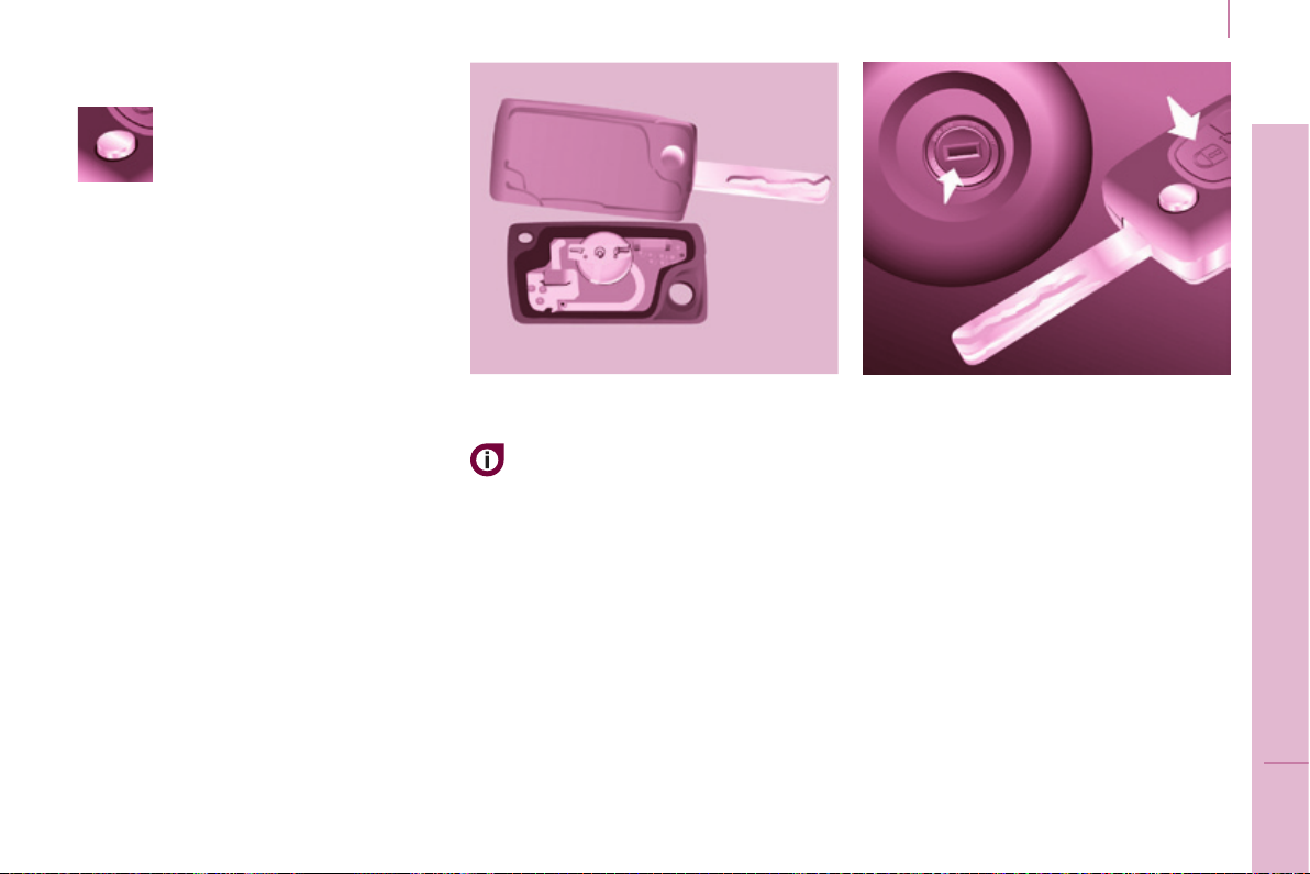
REMOTE COnTROL
Changing the battery
Battery ref.: CR1620 / 3 volts.
The "battery at" information is given
by an audible signal, accompanied by
a message in the screen.
to replace the battery, unclip the
casing using a coin at the ring.
If the remote control does not work
after the battery has been changed,
reinitialise the remote control.
there is a risk of damage if the
replacement battery is not the correct
type.
use only identical batteries
or batteries of an equivalent
type to those recommended by
PeugeOt dealers.
Do not discard the remote control
batteries, they contain metals which
are harmful to the environment.
Deposit them at a PeugeOt
dealership, or at an authorised
collection point.
Reinitialising the remote control
Following changing of the remote
control battery or disconnection of the
vehicle battery, the remote control may
have to be reinitialised.
Wait at least one minute before using
the remote control.
Insert the key in the ignition switch with
the buttons (padlocks) of the remote
control facing you.
Switch on the ignition.
Press the locking padlock for at
least ve seconds within the next
ten seconds.
Switch off the ignition.
Wait at least one minute before using
the remote control.
the remote control is now working
again.
19
READY TO SET OFF
3
Page 22
Access
ELECTROnIC IMMOBILISER
20
All of the keys contain an electronic
immobiliser device.
this device locks the engine supply
system. It is activated automatically
when the key is removed from the
ignition.
After the ignition is switched on, a
dialogue is established between the key
and the electronic immobiliser system.
the metal part of the key must be
unfolded correctly for correct dialogue
to take place.
If you lose your keys
Visit a PeugeOt dealer with the
vehicle's V5 registration certicate and
your identication document.
A PeugeOt dealer will be able
to retrieve the key code and
the transponder code so that a
replacement key can be ordered.
good practice
Do not make any modications to the
electronic immobiliser system.
Operating the remote control, even
when it is in your pocket, may result in
involuntary unlocking of the doors.
the simultaneous use of other
high frequency equipment (mobile
telephones, domestic alarms…), may
interfere with the operation of the
remote control temporarily.
the remote control does not operate
while the key is in the ignition, even if
the ignition is off.
When purchasing a second-hand
vehicle, have the keys memorised by
a PeugeOt dealer, so as to be sure
that the keys in your possession are
the only ones that can be used to start
the vehicle.
Don't forget
When leaving the vehicle, check that
the lighting is off and nothing of value
is visible.
As a safety precaution (with children
on board), remove the key from the
ignition when leaving the vehicle, even
for a short time.
ALARM
If tted on your vehicle, this provides
two types of protection:
- exterior protection: it sounds if a
front/rear door or the bonnet is
opened.
- interior protection: it sounds if
the volume inside the passenger
compartment changes (breaking of
a window or a movement inside the
vehicle).
If your vehicle is tted with a separation
partition, the interior protection is not
active in the load space.
Locking the vehicle with
complete alarm
Setting the alarm
- Switch off the ignition and get out of
the vehicle.
- Set the alarm within ve minutes of
getting out of the vehicle, by locking
or deadlocking using the remote
control. the red LeD, located in the
button, ashes once per second.
Page 23

Access
Disarming
- unlock the vehicle with the remote
control or switch on the ignition, the
red LeD goes off.
Locking the vehicle with
exterior protection only
If, while you are away from the vehicle,
you wish to leave a window partially
open or a pet inside the vehicle, you
should choose exterior protection only.
- Switch off the ignition.
- In the next ten seconds,
press the button until
the red LeD is on
continuously.
- get out of the vehicle.
- Within the next ve minutes, set
the alarm by locking or deadlocking
using the remote control (the red
LED ashes once a second).
Triggering
the siren sounds, the direction indicators
ash for approximately 30 seconds and
the red LED ashes rapidly.
-
t o switch it of f, insert the key and
switch on the ignition.
When the alarm has been triggered ten
times in succession (when triggered for
the eleventh time) it is deactivated. Repeat
the procedure for setting the alarm.
Locking the vehicle without
alarm
- Insert the key in the lock on the
driver's door and lock it.
Do not set the alarm when washing
your vehicle.
Failure of the remote control
When the alarm is set but the remote
control does not operate:
- unlock the doors with the key and
open the door. the alarm is triggered.
- Switch on the ignition in the next ten
seconds. the alarm is disarmed.
Incorrect operation
When the ignition is switched on, if the
red LeD remains on for ten seconds,
there is a fault in the siren connection.
Contact a PeugeOt dealer to have
the system checked.
Automatic setting of the alarm
Depending on the country in which
the vehicle is sold, the alarm is set
automatically approximately 2 minutes
after the last door is closed.
to prevent triggering of the alarm when
a door is opened, you have to press
the remote control unlocking button
again.
Do not make any modications
to the alarm system as this could
cause faults.
FROnT DOORS
From the outside
use the remote control to lock/unlock
the vehicle.
Insert the metal part of the key in the
lock on the driver's side if the remote
control does not work.
From the inside
use the door opening control to unlock
and open the door concerned.
21
READY TO SET OFF
3
Page 24
Access
22
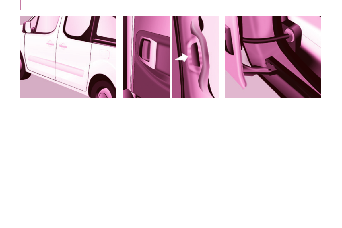
SLIDIng SIDE DOORS
From the outside
Pull the handle towards you then
towards the rear and open the side
door guiding the rearward sliding to
beyond the point of resistance to hold
it open.
A mechanical system prevents opening
of the left-hand side door when the fuel
ller ap is open.
From the inside
unlock the side door using this handle
and open it, guiding the rearward
sliding to the point of resistance. Pass
this point to hold the door open.
Close the side door using the handle
to start the sliding and pass the point
of resistance. then, use the shaped
recess at the top of the door pillar to
guide the door until it locks.
Do not use the grab handle to slide the
door.
good practice
take care not to block the guide space
on the oor to allow the door to slide
correctly.
If your vehicle is parked on a slope,
guide the sliding of the side door. In
fact, the door could open or close more
rapidly due to the slope of the ground
and could cause injury.
For safety and operation reasons, do
not drive with the sliding side doors
open.
Page 25
Access
23
Operation in the event of a
battery failure
Front and side passenger doors
In the event of a battery or of the
central locking fault, use the lock to
lock the doors mechanically.
- to open the door and get out of the
vehicle, pull the interior control.
- to lock the door, insert the key in
the lock, located on the edge of the
door, then turn it one eighth of a
turn.
Driver's door
- Insert the key in the lock, then turn
it to the right to lock or to the left to
unlock.
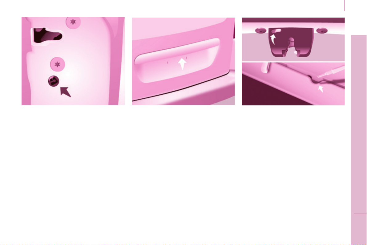
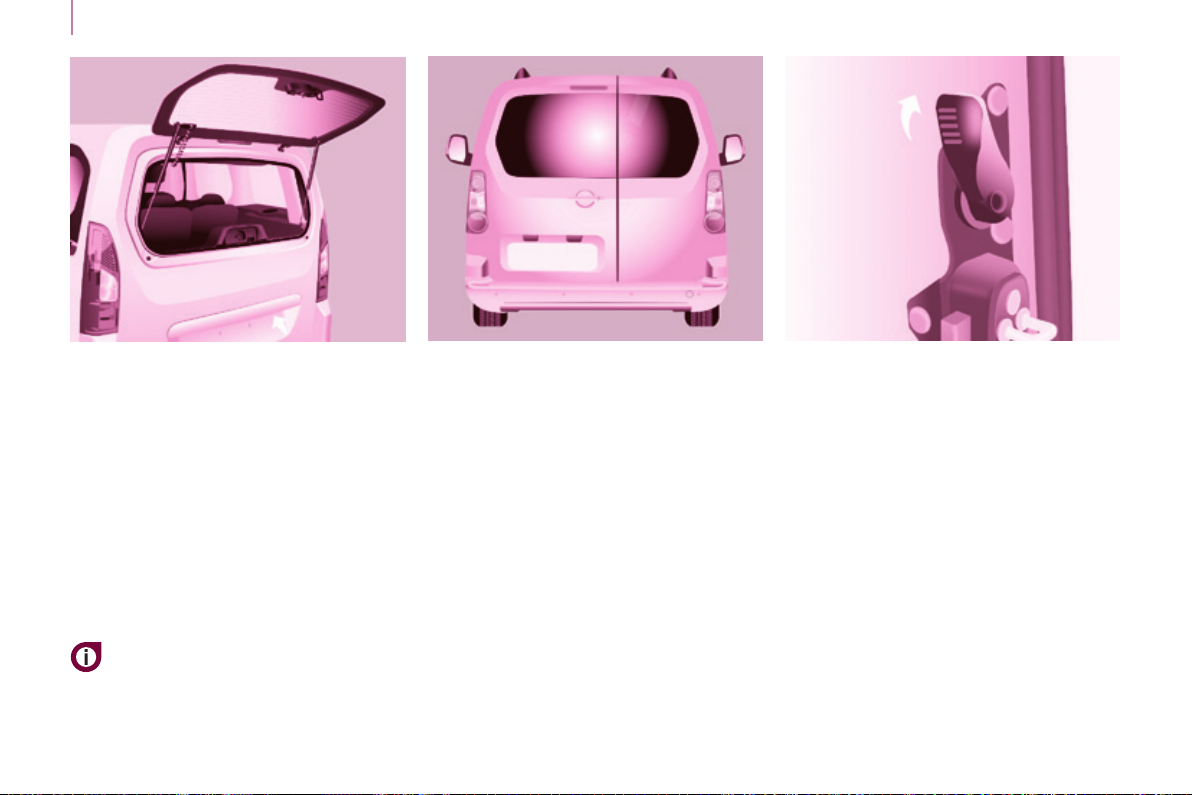
TAILgATE
Opening
From outside
Locking/unlocking is by means of the
remote control.
to open, press the control below the
trim then raise the tailgate.
A pull strap is available to close the
tailgate in the high position.
guide the closing of the tailgate to the
balance point of its travel then apply
a nal press on the tailgate to close it
fully.
From inside
(emergency control)
In the event of a central unlocking
operating fault, this permits unlocking
of the tailgate from the inside.
Insert a small screwdriver in the
opening, between the tailgate and the
oor. To unlock the lock, move the
catch to the left then push the tailgate.
READY TO SET OFF
3
Page 26
24
Access
Tailgate screen
the opening rear screen allows you to
access the rear of the vehicle directly,
without having to open the tailgate.
Opening
After unlocking the vehicle using the
remote control or the key, press the
control and raise the rear screen to
open it.
Closing
Close the rear screen by pressing
the centre of the glass until it is fully
closed.
the tailgate and tailgate screen
cannot both be open at the
same time, to prevent damage to
the screen.
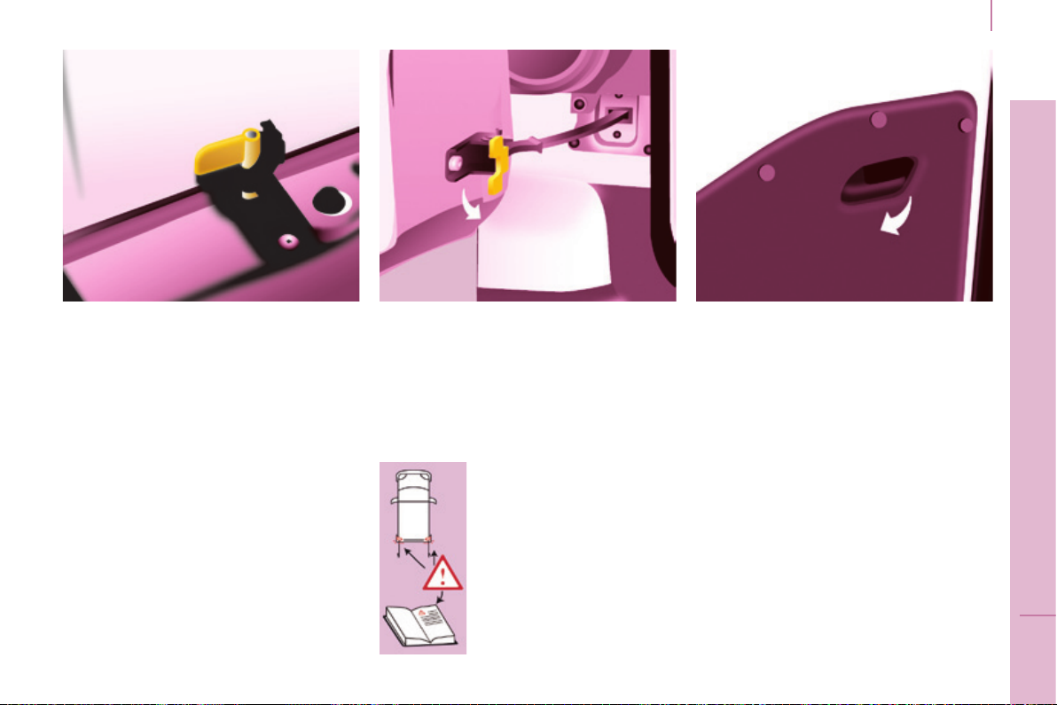
HIngED REAR DOORS
the hinged rear doors are
asymmetrical (2/3 - 1/3), with the
smaller door on the right.
They are tted with a central lock.
From outside
to open, pull the handle towards you.
Pull the lever to open the right-hand
door.
to close, start with the right-hand door
then close the left-hand door.
With the roof rear ap, the rear bumper
has been reinforced to serve as a
footrest when entering the vehicle.
Page 27
Access
25
In practice
It is possible to drive with the righthand door open to make it easier to
carry long loads. the left-hand door is
kept closed by the distinctive "yellow"
lock, positioned at the base of the door.
this closed door must not be used as
a load retainer.
Driving with the right-hand door open
is a special dispensation. Comply with
the usual safety indications to warn
other drivers.
Opening to approximately 180°
A check strap system permits extension
of the opening from approximately 90°
to approximately 180°.
Pull the yellow control when the door
is open.
the check strap will engage again
automatically on closing.
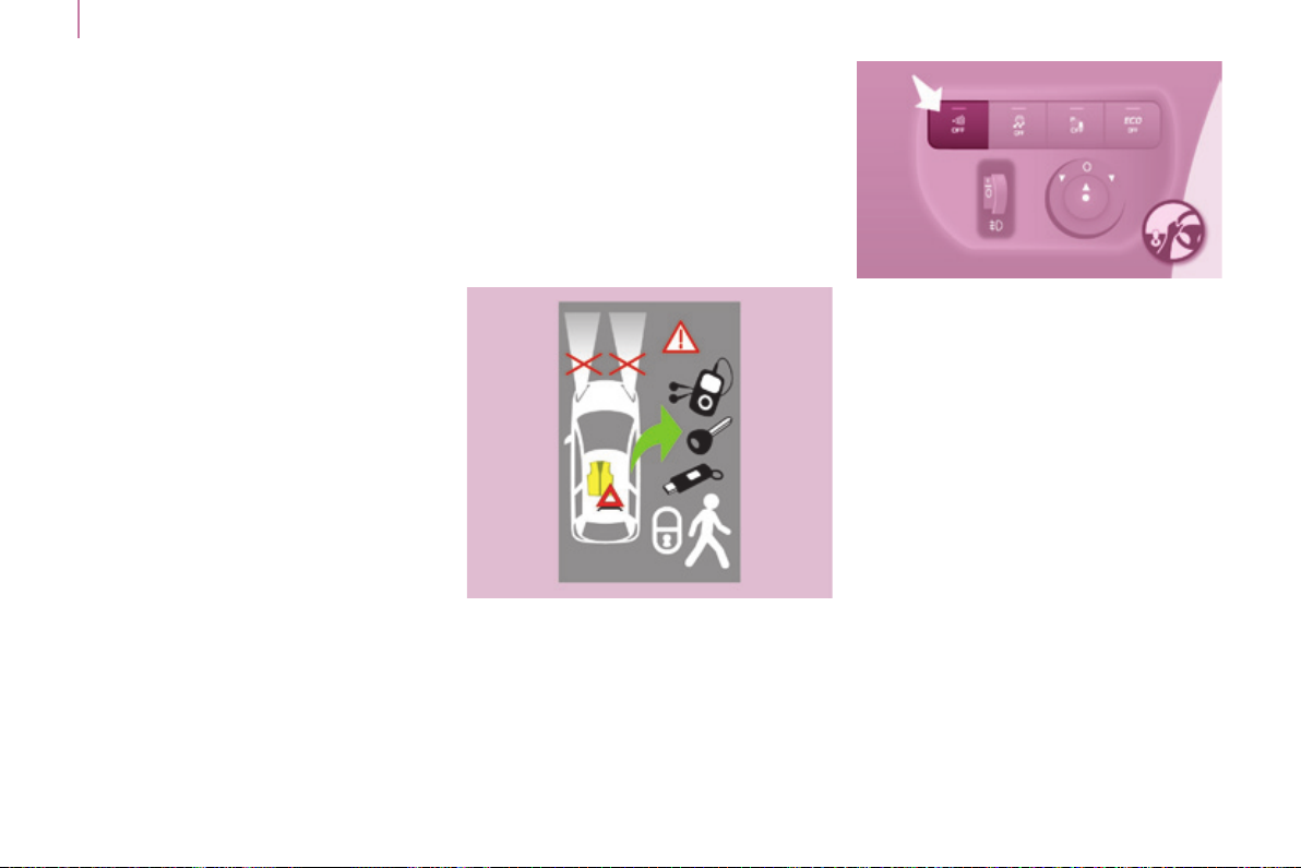
When parked with the
rear doors open to 90°,
the doors mask the rear
lamps. to signal your
position to other road
users driving in the same
direction who may not
have seen your vehicle,
use a warning triangle
or other device required
by the legislation in your
country.
From inside
When present on the vehicle, pulling
this handle towards you opens the lefthand door.
READY TO SET OFF
3
Page 28
Access
26
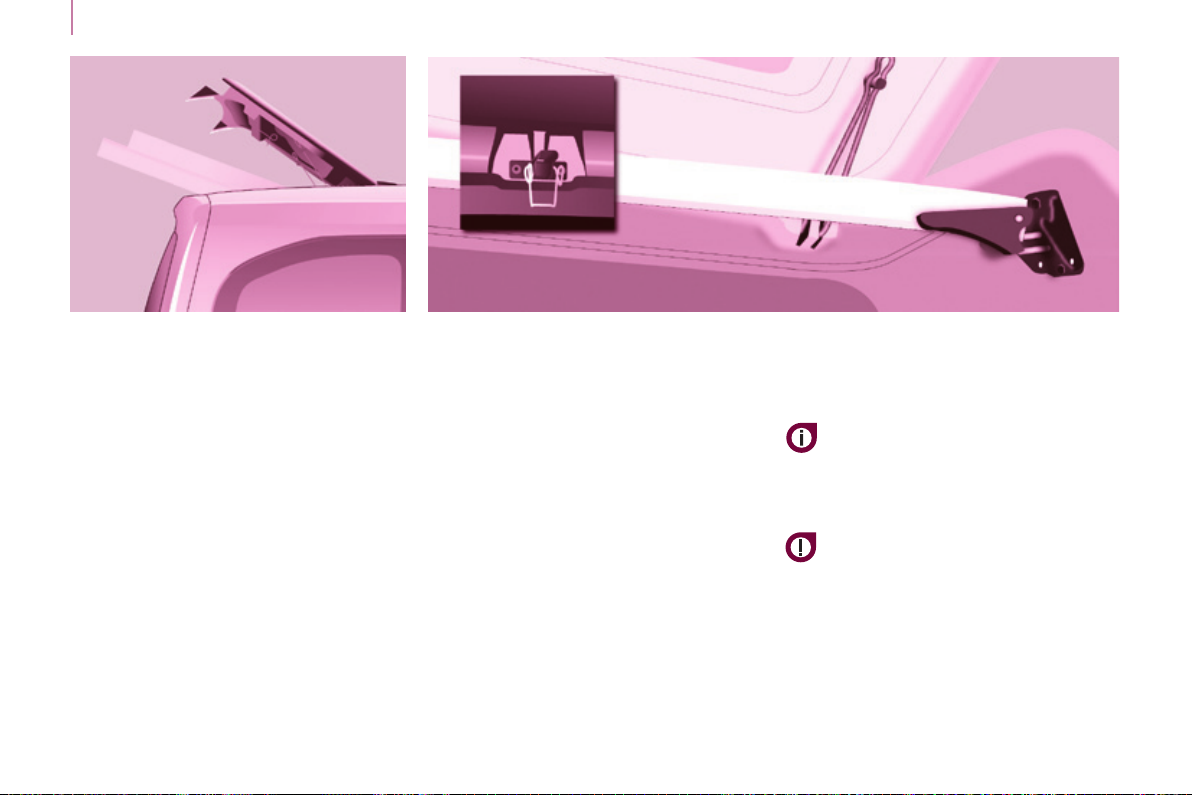
REAR ROOF FLAP
This rear roof ap is only compatible
with side-hinged rear doors.
To open the rear roof ap:
- raise the black paddle of the toggle,
- relieve the toggle by pressing the
rear roof ap (downwards) then
release the hook,
- lift the rear roof ap,
- pass the point of resistance to
secure the rear roof ap using the
support stays.
Never drive without the stays in place.
To close the rear roof ap:
- check that the support bar is
secured correctly,
- lower the rear roof ap,
- while pressing the rear roof ap
(downwards), take hold of the
two loops of the spring then place
the hook in its housing,
- lower the black paddle to secure
the rear roof ap.
Securing the rear roof ap places it on
the seal correctly and ensures sealing
without noise.
Support bar
A support bar is provided for
transporting long loads, after opening
the rear roof ap.
Fold back the support bar by lifting the
lever.
guide it to the door pillar.
Support the long loads to be
transported, lift them and reposition the
support bar with one hand.
ensure that it is secured correctly by
pressing the handle downwards past
the point of resistance and secure the
loads rmly.
the side supports can be used as
hooking points.
Never attach any load to the rear roof
ap.
the rear bumper has been
reinforced to serve as a footrest
when entering the vehicle.
Never drive without the support bar in
place.
the rear doors only lock when the
support bar is installed.
When the rear roof ap is open, take
care when driving where height is
restricted.
Never rest loads directly on the rear
doors.
Comply with the usual indications, to
warn other drivers.
Reserve the use of the rear roof ap
for short journeys.
Page 29
Access
Anti-intrusion security
Locking while driving
When the vehicle moves off, as soon
as you reach approximately 6 mph
(10 km/h), the system locks the doors.
the characteristic central locking noise
is heard. the LeD in the switch on
the dashboard central switch panel
comes on.
During the journey, opening a door
results in complete unlocking of the
vehicle.
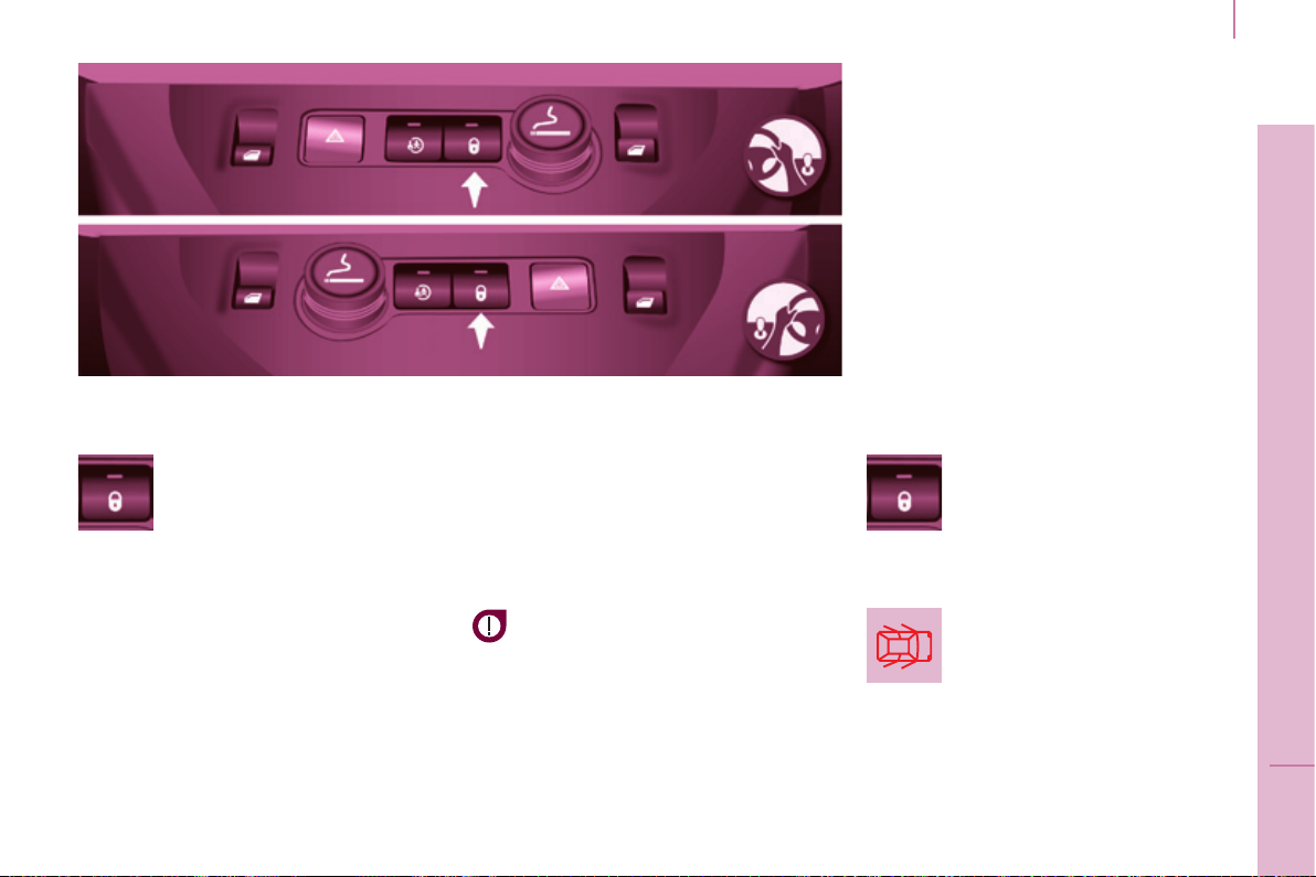
27
CEnTRAL LOCKIng
An initial press permits
central locking of the vehicle,
when all of the doors are
closed.
A second press permits central
unlocking of the vehicle.
the control is inactive when the vehicle
has been locked using the remote
control or the key from the outside.
the doors can still be opened from the
inside.
the control switch LeD:
-
ashes when the doors are locked with
the vehicle stationary and the engine off,
-
comes on when the doors are locked
and from the time the ignition is
switched on.
Driving with the doors locked may
make access to the interior more
difcult in an emergency.
Activating / deactivating the
function
With the ignition on, press
and hold this switch to
activate or deactivate the
function.
Door open warning lamp
If this warning lamp comes
on, check that all of your
vehicle's doors are closed
correctly.
READY TO SET OFF
3
Page 30
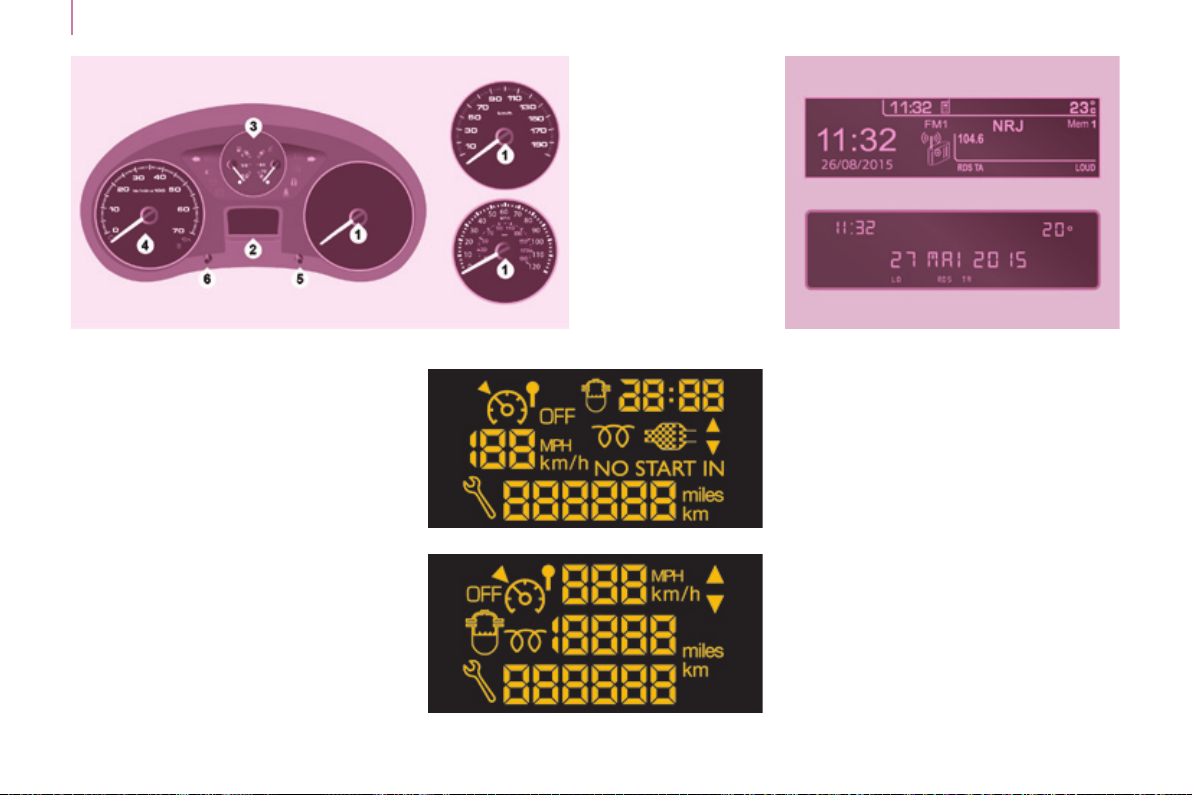
Instruments and controls
28
InSTRUMEnT PAnEL Display screens Screens Dials
1. Distance recorder in kilometres /
miles.
2. Display screen.
3. Fuel gauge, coolant temperature.
4. Rev counter.
5. trip distance recorder / service
indicator reset.
6. Instrument panel lighting dimmer.
Level 1
the format of the information
presented in the screen depends on
the vehicle's equipment level.
Level 2
with the touch screen
Page 31

DATE AnD TIME
Centre console without screen
to adjust the time, use the
left-hand button on the
instrument panel:
- Turn to the left: the minutes ash.
- turn to the right to increase the
minutes (hold the button to the right
for rapid scrolling).
- Turn to the left: the hours ash.
- turn to the right to increase the
hours (hold the button to the right
for rapid scrolling).
Instrument panel without screen
- turn to the left: 24H or 12H is
displayed.
- turn to the right to select 24H
or 12H.
- turn to the left to complete the time
adjustment.
After approximately 30 seconds
without any action, the screen returns
to the normal display.
Instruments and controls
29
Centre console with screen
the display - time sequence
is linked according to model
(version). the access to
the "Date" adjustment is
only active when the model
version offers a date in words.
READY TO SET OFF
3
Page 32

Instruments and controls
30
Screen C
Press the MEnU button.
using the arrows, select
PERSOnALISATIOn
COnFIgURATIOn.
Press to conrm the
selection.
using the arrows, select
DISPLAY COnFIgURATIOn.
Press to conrm the
selection.
using the arrows, select
ADJUST DATE AnD TIME.
Press to conrm the
selection.
Adjust the settings one by
one conrming by pressing
the OK button.
then select the OK tab in the
screen and conrm.
Page 33

Touch screen
F Select the "Conguration"
F In the secondary page,
menu.
press on "Time/Date".
F Select "Adjust time" or "Adjust
date" and modify the settings using
the number keypad, then conrm.
Instruments and controls
31
F Press "Conrm" to quit.
READY TO SET OFF
3
Page 34

Instruments and controls
WARnIng LAMPS
each time the vehicle is started: a series of warning lamps comes on applying a self-test check. they go off almost immediately.
32
Engine running: the lamp becomes a warning if it remains on continuously or ashes.
this initial warning may be accompanied by an audible signal and a message in the screen.
Do not ignore these warnings.
Warning lamp is indicates Solution - action
STOP
Parking
brake / Brake
uid level /
EBFD
Engine oil
pressure and
temperature
on, associated
with another
warning
lamp and
accompanied
by a message
in the screen.
on.
on. low brake uid level. Top up using a uid recommended by PEUGEOT.
remaining on even
though the level
is correct and
associated with the
ABS warning lamp.
on while
driving.
remaining on,
even though the
level is correct.
major faults linked with
the "Brake uid level",
"engine oil pressure and
temperature", "Coolant
temperature", "electronic
brake force distribution" and
"Power steering" warning
lamps.
that the parking brake is applied
or has not been released fully.
a fault with the electronic
brake force distribution.
low pressure or a high
temperature.
a major fault.
You must stop as soon as it is safe to do
so. Park and switch off the ignition. Have it
checked by a PEUgEOT dealer or a qualied
workshop.
Releasing the parking brake switches off the
warning lamp.
You must stop as soon as it is safe to do so.
Park and switch off the ignition.
Have it checked by a PEUgEOT dealer or a
qualied workshop.
Park and switch off the ignition then allow to cool.
Visually check the level.
Chapter 7, "Levels" section.
Have it checked by a PeugeOt dealer or a
qualied workshop.
Page 35

Instruments and controls
Warning lamp is indicates Solution - action
Coolant
temperature
and level
Service
Seat belt not
fastened
ECO
on with needle
in the red
zone.
ashing. a drop in the coolant level.
on temporarily. minor faults or warnings.
remaining on. major faults.
on then
ashing.
accompanied
by an audible
signal then
remains on.
on.
ashes for a
few seconds,
then goes off.
an abnormal increase in
temperature.
the driver and/or front
passenger has not fastened
their seat belt.
the vehicle is moving with
the driver's and/or front
passenger's seat belt not
fastened.
the Stop & Start system
has put the engine in
StOP mode following a
vehicle stop (red light, trafc
jam, etc...).
StOP mode is temporarily
unavailable.
or
StARt mode has been
invoked automatically.
Park and switch off the ignition then allow to cool.
Visually check the level.
Chapter 7, "Levels" section.
Contact a PEUGEOT dealer or a qualied
workshop.
Consult the alert log in the display or screen.
If your vehicle is equipped with a trip computer or
a screen: refer to the "Steering mounted controls"
section in Chapter 4.
Contact a PEUGEOT dealer or a qualied
workshop.
Pull the strap then insert the tongue in the buckle.
Check that the seat belt is fastened by pulling the
strap.
Chapter 5, "Seat belts" section.
As soon as you want to move off, the warning
lamp goes off and the engine restarts
automatically in StARt mode.
Chapter 3, "Stop & Start" section.
33
READY TO SET OFF
3
Page 36

Instruments and controls
Warning lamp is indicates Solution - action
34
Front / lateral
airbag
ashing or
remaining on.
a failure of an airbag.
Have the system checked by a PeugeOt
dealer or a qualied workshop without delay.
Chapter 5, "Airbags" section.
Front
passenger's
airbag
deactivated
Low fuel
level
EOBD
emission
control
system
Battery
charge
on.
on with gauge
needle in the
red zone.
ashing.
ashing or
remaining on.
on.
ashing.
remaining on,
in spite of the
checks.
the intentional deactivation
of this airbag in the
presence of a rearward
facing child seat.
When it rst comes on,
there remains around
8 litres of fuel in the tank.
the distance you can drive
on this fuel depends on
your style of driving and the
engine type.
cutting off of the fuel supply
following a serious impact.
a failure of the system.
a fault in the charging
circuit.
placing of the active
functions on standby
(economy mode).
an ignition or injection
malfunction.
Chapter 5, "Airbags" or "child safety" section.
You must ll up with fuel to avoid running out.
this warning lamp comes on each time you
switch on the ignition until you have lled up.
Capacity of the tank: approximately 60 litres.
Never risk driving until the tank is empty, this
could damage the emissions and injection
systems.
Restore the supply.
Chapter 7, "Fuel" section.
there is a risk of damage to the catalytic
converter. Have it checked by a PeugeOt
dealer or a qualied workshop.
Check the battery terminals, …
Chapter 8, "Battery" section.
Chapter 8, "Battery" section.
Have it checked by a PeugeOt dealer or a
qualied workshop.
Page 37

Instruments and controls
Warning lamp is indicates Solution - action
the vehicle retains conventional steering without
assistance. Have it checked by a PeugeOt
dealer or a qualied workshop.
Check that all of the doors are closed.
the vehicle retains conventional braking.
Have it checked by a PeugeOt dealer or a
qualied workshop.
the system optimises traction and improves the
directional stability of the vehicle.
Chapter 5, "Driving safety" section.
e.g.: check the pressure of the tyres.
Have it checked by a PeugeOt dealer or
a qualied workshop. (Wheel speed sensor,
hydraulic valve block, ...).
Check the tyre pressure as soon as possible.
this check must be done with the tyres cold.
Detection of under-ination is no longer assured.
Have it checked by a PeugeOt dealer or a
qualied workshop.
ABS
+
Power
steering
Door open
detection
ABS remaining on.
ESC
Under-
ination
on.
on and accompanied
by a message in the
screen.
ashing.
remaining on.
on.
ashing then
remaining on,
accompanied by the
Service warning
lamp, and depending
on equipment, the
display of a message.
a fault with the
system.
that a door is not
closed correctly.
a fault with the antilock braking system.
triggering of the ASR
or DSC regulation.
a fault with the
system.
E.g.: under-ination
of the tyres.
the tyre pressure is
too low in or more
wheels.
the tyre pressure
monitoring system
has a fault or one of
the wheels does not
have a sensor.
35
Particle lter on.
a problem with the
particle lter (fuel
additive level, risk of
blockage, ...).
Have the lter checked by a PEUGEOT dealer or
a qualied workshop.
Chapter 7, "Levels" section.
READY TO SET OFF
3
Page 38

Instruments and controls
Warning lamp is indicates Solution - action
36
Dipped beam
headlamps /
Daytime
running
lamps
on.
a manual selection or
automatic illumination of
headlamps.
illumination of the dipped beam headlamps
from the time the ignition is switched on:
daytime running lamps (depending on the
country in which the vehicle is sold).
turn the ring on the lighting control stalk to the
second position.
Chapter 4, "Steering mounted controls" section.
Main beam
headlamps
Direction
indicators
Front
foglamps
Rear
foglamps
pulling of the stalk towards
you.
ashing with
audible signal.
on. a manual selection.
on. a manual selection.
a change of direction via
the lighting stalk.
Pull the stalk to return to dipped beam
headlamps.
to the Right: control to be pushed upwards.
to the Left: control to be pushed downwards.
the foglamps only operate if the sidelamps or
dipped beam headlamps are on.
the foglamps only operate if the sidelamps or
dipped beam headlamps are on.
In conditions of normal visibility, switch them off
to avoid breaking the law.
"this lamp is a dazzling red."
Page 39

Instruments and controls
Warning lamp in the
screen
Cruise
control
Speed limiter on. speed limiter selected.
gear shift
indicator
Diesel preheating
Presence of
water in the
Diesel lter
Service
spanner
Time ashing. adjustment of the time.
is indicates Solution - action
on. cruise control selected.
on.
on.
on and
accompanied by
a message in the
screen.
on.
a recommendation
independent of the type and
density of trafc.
climatic conditions requiring
pre-heating.
water in the Diesel lter.
that a service will be due
shortly.
Manual selection.
Chapter 4, "Steering mounted controls" section.
Manual selection.
Chapter 4, "Steering mounted controls" section.
to reduce fuel consumption, change to an
appropriate gear with a manual gearbox.
the driver retains responsibility to follow this
indication or not.
Wait until the warning lamp goes off before
operating the starter.
Have the lter bled by a PEUGEOT dealer or a
qualied workshop without delay.
Chapter 7, "Checks" section.
According to country.
Refer to the list of checks in the warranty and
maintenance record.
Have the service carried out by a PeugeOt
dealer or a qualied workshop.
use the left-hand button on the instrument panel.
Chapter 3, "Instruments and controls" section.
37
READY TO SET OFF
3
Page 40

Instruments and controls
AdBlue® additive
38
Alert Information Solution - action
st
level of alert
1
+
In the display
screen.
In the touch
screen.
there is an audible signal when the ignition is switched on.
the warnings are intermittent and then become permanent
when switching on the ignition or when driving.
the remaining driving range is counted down from
1 500 miles (2 400 km) to 375 miles (600 km).
The range gure reduces in steps of 200 miles (300 km).
nd
level of alert
2
there is an audible signal when the ignition is
switched on.
the warnings are intermittent (every 30 seconds)
and then become permanent every time the ignition
is switched on or when driving.
the remaining driving range is counted down from
350 miles (600 km) to zero, reducing in steps of
30 miles (50 km).
temporary display: "NO StARt IN".
Select:
- "Driving assistance".
- "Diagnostic".
the contents of the additive tank has dropped to a
level sufcient for a range of less than 1 500 miles
(2 400 km).
Have the tank topped-up using an AdBlue
container or bottles.
You must have the AdBlue
not wait for a breakdown.
the driving range is displayed.
®
®
additive topped-up and
rd
3
level of alert
the AdBlue
®
additive tank is empty.
For more information, refer to Chapter 7, "AdBlue additive" section.
Starting is impossible.
It is essential to add at least 3.8 litres of AdBlue®
additive to the additive tank.
Page 41

Instruments and controls
SCR emissions control system
Alerts Information Solution - action
the uReA, Service and diagnostic warning lamps
come on, an SCR emissions control system fault
has been detected.
+
After 30 miles (50 km) without additive
+
Conrmation of the fault which is not related to a
lack of additive.
The fault is conrmed.
the next time the ignition is switched on, the
authorised driving range will be displayed in miles
(kilometres) and the alert will be repeated every
30 seconds.
the limit of the driving range has been reached,
exhaust emissions levels are above the limits.
Starting is impossible.
- BlueHDi Diesel
this is is temporary fault, the alert disappears as
soon as the exhaust emissions return to normal
levels.
the remaining driving range 700 miles (1 100 km).
Go to a PEUGEOT dealer or a qualied workshop
as soon as possible to avoid a breakdown.
to restart the engine, you must contact a
PEUGEOT dealer or a qualied workshop.
39
READY TO SET OFF
3
Page 42

Instruments and controls
40
FUEL gAUgE COOLAnT TEMPERATURE
The needle is positioned before the
the fuel level is tested each time the
key is turned to the "running" position.
the gauge is positioned on:
- 1: the fuel tank is full,
approximately 60 litres.
- 0: the reserve is now being used,
the warning lamp comes on
continuously. the reserve when
the warning rst comes on is
approximately 8 litres.
red zone: normal operation.
In arduous conditions of use or hot
climatic conditions, the needle may
move close to the red graduations.
What you should do if the needle
enters the red zone:
Reduce your speed or let the engine
run at idle.
What you should do if the warning
lamp comes on:
- stop immediately, switch off the
ignition. the fan may continue to
operate for a certain time, up to
approximately 10 minutes,
- wait for the engine to cool down in
order to check the coolant level and
top it up if necessary.
As the cooling system is pressurised,
follow the procedure below to avoid the
risk of scalding:
- wait at least one hour after
switching off the engine before
carrying out any work,
- unscrew the cap by 1/4 turn to
allow the pressure to drop,
- when the pressure has dropped,
check the level in the header tank,
- if necessary, remove the cap to top
up.
If the needle remains in the red
zone, have the system checked by
a PEUGEOT dealer or a qualied
workshop.
Refer to chapter 7, "Levels"
section.
Refer to chapter 7, "Fuel" section.
Page 43

Instruments and controls
EMISSIOnS COnTROLS
eOBD (european On Board
Diagnosis) is a diagnostics
system which complies
with, among others, the
standards on the authorised
emissions of:
- CO (carbon monoxide),
- HC (unburnt hydrocarbons),
- NOx (nitrous oxides) or particles,
detected by oxygen sensors placed
upstream and downstream of the
catalytic converters.
the driver is warned of any malfunction
of this emission control system by the
illumination of this specic warning
lamp in the instrument panel.
there is a risk of damage to the
catalytic converter. Have it checked
by a PEUGEOT dealer or a qualied
workshop.
UnDER-InFLATIOn DETECTIOn
this system
continuously monitors
the pressures of the four
tyres, as soon as the
vehicle is moving.
A pressure sensor is located in the
valve of each tyre (except the spare
wheel).
the system triggers an alert if a drop
in pressure is detected in one or more
tyres.
The tyre under-ination detection
system is an aid to driving which
does not replace the need for
vigilance on the part of the driver.
this system does not avoid the
need to check the tyre pressures
regularly (including the spare
wheel) and before a long journey.
Driving with under-inated tyres
adversely affects road holding,
extends braking distances and causes
premature tyre wear, particularly under
arduous conditions (vehicle loaded,
high speed, long journey).
Driving with under-inated tyres
increases fuel consumption.
the tyre pressures for your vehicle
can be found on the tyre pressure
label.
Refer to chapter 9, "Identication
markings" section.
the tyre pressures must be checked
when the tyres cold (vehicle stopped
for 1 hour or after driving for less then
6 miles (10 km) at moderate speed).
Otherwise, add 0.3 bar to the values
indicated on the label.
41
READY TO SET OFF
3
Page 44

Instruments and controls
42
The alert is given by the xed
illumination of this warning lamp,
accompanied by an audible signal,
and depending on equipment, the
display of a message.
In the event of a problem on one of
the tyres, the symbol or the message
appears, according to equipment, to
identify it.
- Reduce speed, avoid sudden
steering movements or harsh brake
applications.
- Stop as soon as it is safe to do so.
- In the event of a puncture, use
the temporary puncture repair kit
or the spare wheel (according to
equipment),
or
- if you have a compressor, the one
in the temporary puncture repair
kit for example, check the four tyre
pressures when cold,
or
- if it is not possible to check the
tyre pressures at the time, drive
carefully at reduced speed.
the loss of pressure detected
does not always lead to visible
deformation of the tyre. Do not rely
on just a visual check.
the alert is maintained until
the tyre or tyres concerned is
reinated, repaired or replaced.
the spare wheel (space-saver type or
a steel rim) does not have a sensor.
Operating faultUnder-inflation alert
The ashing and then
xed illumination of the
under-ination warning
lamp accompanied by the
illumination of the "Service" warning
lamp, and depending on equipment,
the display of a message indicates a
fault with the system.
In this case, monitoring of the tyre
pressures is not assured.
this alert is also displayed when
one or more wheels is not tted
with a sensor (for example, a
space-saver or steel spare wheel).
go to a PeugeOt dealer or a
qualied workshop to have the system
checked or, following the repair of a
puncture, to have the original wheel,
equipped with a sensor, retted.
Page 45

SERVICE InDICATOR
this programmes service intervals
according to the use of the vehicle.
Operation
A few moments after the ignition
has been switched on, the spanner
indicating a service operation comes
on; the display for the total distance
recorder gives (in round gures) the
distance remaining before the next
service.
the points at which a service is due
are calculated from the last indicator
zero reset.
the point at which a service is due is
determined by two parameters:
- the distance travelled,
- the time which has elapsed since
the last service.
More than 1 000 miles/km before the
next service is due
Example: 4 800 miles/km remain
before the next service is due. When
the ignition is switched on and for a
few seconds, the screen shows:
A few seconds after the ignition is
switched on, the oil level is displayed
(depending on version), then the total
distance recorder resumes normal
operation showing the total and trip
distances.
Less than 1 000 miles/km before the
next service is due
each time the ignition is switched on and for a
few seconds, the spanner ashes and the number
of miles/kilometres remaining is displayed:
Instruments and controls
A few seconds after the ignition is
switched on, the oil level is displayed
(depending on version), then the total
distance recorder resumes normal
operation and the spanner remains on.
this indicates that a service should be
carried out shortly.
Service overdue
each time the ignition
is switched on and for a
few seconds, the spanner
ashes and the excess
distance is displayed.
With the engine running the spanner
remains on until the service has been
carried out.
For BlueHDi Diesel versions, this
alert is also accompanied by the xed
illumination of the Service warning
lamp, on switching on the ignition.
43
the distance remaining before the
next service may be weighted by
the time factor, depending on the
type of driving.
For BlueHDi Diesel versions, the
spanner can also come on early,
according the level of deterioration
of the engine oil. Deterioration of the
engine oil depends on the conditions of
use of the vehicle.
READY TO SET OFF
3
Page 46

Instruments and controls
Zero reset
Your PEUGEOT dealer or a qualied
44
workshop carries out this operation
after each service.
However, if you carry out the service
yourself, the re-set procedure is as
follows:
- switch off the ignition,
- press and hold the trip recorder
reset button,
- switch on the ignition.
the display begins a countdown.
When the display shows "=0", release
the button; the spanner disappears.
Oil level correct
Low oil level
Flashing of "OIL",
linked with the
service warning lamp,
accompanied by an
audible signal and a message in the
screen, indicates a low oil level which
could damage the engine.
If the low oil level is conrmed by a
check using the dipstick, it is essential
that the level is topped up.
Dipstick
A = maximum, never exceed
this level as a surplus of oil
may damage the engine.
Contact a PeugeOt dealer
or a qualied workshop
without delay.
B = minimum, top up the level
via the oil ller cap, using the
grade of oil suited to your
engine.
Trip recorder zero reset button
After this operation, if you wish
to disconnect the battery, lock
the vehicle and wait for at least ve
minutes, otherwise the zero re-set will
not be registered.
Engine oil level indicator
Depending on your vehicle's engine,
when the ignition is switched on,
the engine oil level is indicated for
a few seconds, after the service
information.
Oil level gauge fault
Flashing of "OIL--"
indicates a
malfunction of the
engine oil level
indicator. Contact a PeugeOt dealer
or a qualied workshop.
the level read will only be correct
if the vehicle is on level ground
and the engine has been off for
more than 30 minutes.
With the ignition on, press
the button until the zeros
appear.
Lighting dimmer
With the lighting on,
press the button to vary
the brightness of the
instruments and controls.
When the lighting
reaches the minimum (or
maximum) setting, release the button
then press it again to increase (or
reduce) the brightness.
As soon as the lighting is of the
required brightness, release the button.
Page 47

Gearbox and steering wheel
45
STEERIng WHEEL ADJUSTMEnT
When the vehicle is stationary,
release the steering wheel adjustment
mechanism by pulling the lever.
Adjust the steering wheel for height
and reach, then lock the mechanism by
pushing the lever fully forward.
5-speed
MAnUAL gEARBOx
to change gear easily, always depress
the clutch pedal fully.
to prevent the mat from becoming
caught under the pedal:
- ensure that the mat is positioned
and secured correctly on the oor,
- never t one mat on top of another.
When driving, avoid leaving your hand
on the gear knob as the force exerted,
even if slight, may wear the internal
components of the gearbox over time.
6-speed
Engaging reverse gear
In the 6-speed conguration, raise the
collar below the gear knob.
the lever should be moved slowly
to reduce noise.
to engage reverse gear, wait until the
vehicle has come to a complete stop.
Changing into 5th or 6th gear
to engage the gear correctly, move the
gear lever fully to the right.
READY TO SET OFF
3
Page 48

Gearbox and steering wheel
46
gEAR SHIFT InDICATOR
System which reduces fuel
consumption by recommending the
most appropriate gear.
With an electronic gearbox, the system
is only active in manual mode.
Operation
Depending on the driving situation and
your vehicle's equipment, the system
may advise you to skip one (or more)
gear(s). You can follow this instruction
without engaging the intermediate
gears.
the gear engagement
recommendations must not be
considered compulsory. In fact, the
conguration of the road, the amount
of trafc and safety remain determining
factors when choosing the best
gear. therefore, the driver remains
responsible for deciding whether or
not to follow the advice given by the
system.
this function cannot be deactivated.
the information appears in
the instrument panel in the
form of an arrow.
the system adapts its gear
change recommendation
according to the driving conditions
(slope, load, ...) and the demands
of the driver (power, acceleration,
braking, ...).
the system never suggests:
- engaging rst gear,
- engaging reverse gear.
Page 49

Gearbox and steering wheel
6-SPEED ELECTROnIC gEARBOx
Mode selection
- automatic mode: gear selector in
position A.
- manual mode: gear selector in
position M.
For safety:
It is only possible to come out
of position n if the brake pedal is
pressed.
the change from position A (driving in
automatic mode) to position M (driving
in manual mode) or vice versa can be
made at any time. the warning lamp A
goes off in the instrument panel.
Moving off
- to start the engine, the gear
selector must be in position n.
- Press rmly on the brake pedal.
- Operate the starter.
- When the engine is running, place
the gear selector on R, A or M as
desired.
- Release the brake pedal and
accelerate.
If the gear selector is not in position n,
and/or if the brake pedal is not
pressed, the engine will not start.
Repeat the above procedure.
Reverse gear
Engaging reverse gear
Move the gear selector to R.
Only attempt to select reverse gear
when the vehicle is stationary.
neutral
Changing to neutral
Move the gear selector to n. If the
vehicle is moving, do not select this
position even momentarily.
47
READY TO SET OFF
3
Page 50

Gearbox and steering wheel
Automatic mode
48
Move the gear selector to A.
the gearbox then operates in
automatic mode, without any action on
your part.
It constantly selects the gear that is
best suited to the following conditions:
- driving style,
- road prole,
- optimum fuel consumption.
Manual mode
Move the gear selector to M.
Changing to automatic
mode
Changing to manual mode
Changing gear
Pull on the "+" control
paddle to change up.
Pull on the "-" control
paddle to change
down.
- If the vehicle stops or reduces
speed (for example when
approaching a stop sign),
the gearbox changes down
automatically, to rst gear if
needed.
- It is not necessary to release the
accelerator completely during gear
changes.
- A gear change instruction is
accepted only if the engine speed
permits.
- For safety reasons, depending on
the engine speed, a change down
may be performed automatically.
In situations of high engine speeds
(heavy acceleration), a change
up will not occur unless the driver
operates the electronic gearbox control
paddle.
Acceleration
For optimum acceleration (e.g. to
overtake another vehicle), simply
press the pedal beyond the point of
resistance at the end of its travel, by
pressing down rmly.
Vehicle stationary, with the
engine running
In the event of a prolonged stop with
the engine running, the gearbox
changes automatically to neutral n.
Stopping the vehicle
Before stopping the engine, put the
gear selector in position n.
In all cases, it is essential to apply
the parking brake. Check that the
parking brake warning lamp is on in the
instrument panel.
Before doing anything in the
engine compartment, check that
the gear selector is in neutral n.
Page 51

STOP & START
the Stop & Start system puts the
engine temporarily on standby - StOP
mode - during stops in the trafc (red
lights, trafc jams, or other...). The
engine restarts automatically - StARt
mode - as soon as you want to move
off. the restart takes place instantly,
quickly and silently.
Perfect for urban use, the Stop & Start
system reduces fuel consumption and
exhaust emissions as well as the noise
level when stationary.
Operation
going into engine STOP mode
the "ECO" warning lamp
comes on in the instrument
panel and the engine goes
into standby:
- with a manual gearbox, at speeds
below 12 mph (20 km/h), when you
put the gear lever into neutral and
release the clutch pedal,
- with a 6-speed electronic
gearbox, at speeds below 5 mph
(8 km/h), when you press the brake
pedal or put the gear lever into
position n.
If your vehicle is tted with the system,
a time counter calculates the sum of
the periods in StOP mode during a
journey. It rests itself to zero every time
the ignition is switched on with the key.
With a 6-speed electronic
gearbox, for your comfort during
parking manoeuvres, StOP mode
is not available for a few seconds after
coming out of reverse gear.
StOP mode does not affect the
functionality of the vehicle, such as
braking, power steering, for example.
Never refuel with the engine in
StOP mode; you must switch off
the ignition with the key.
Stop & Start
Special cases: STOP mode
unavailable
StOP mode is not invoked when:
- the driver's door is open,
- the driver's seat belt is not
fastened,
- the vehicle has not exceeded
6 mph (10 km/h) since the last
engine start using the key,
- the engine is needed to maintain
a comfortable temperature in the
passenger compartment,
- demisting is on,
- some special conditions (battery
charge, engine temperature,
braking assistance, ambient
temperature...) where the engine
is needed to assure control of a
system.
In this case, the "ECO"
warning lamp ashes for a
few seconds, then goes off.
This operation is perfectly normal.
49
READY TO SET OFF
3
Page 52

Stop & Start
going into engine START mode
50
- with a manual gearbox, when you
- with a 6-speed electronic
With a manual gearbox in StOP
mode, if a gear is engaged without
fully depressing the clutch pedal, a
warning lamp comes on or a message
is displayed asking you to depress the
clutch pedal to restart the engine.
the "ECO" warning lamp
goes off and the engine
starts:
fully depress the clutch pedal,
gearbox:
● gear lever in position A or M,
when you release the brake
pedal,
● or gear lever in position n and
the brake pedal released, when
you move the gear lever to
position A or M,
● or when you engage reverse
gear.
Special cases: START invoked
automatically
For your safety and comfort, StARt is
invoked automatically when:
- you open the driver's door,
- you unfasten the driver's seat belt,
- the speed of the vehicle exceeds
15 mph (25 km/h) with a manual
gearbox or 7 mph (11 km/h) with
the 6-speed electronic gearbox
system,
- some special conditions (battery
charge, engine temperature,
braking assistance, ambient
temperature...) where the engine
is needed to assure control of a
system.
In this case the "ECO"
warning lamp ashes for
few seconds, then goes off.
This operation is perfectly normal.
Deactivation
At any time, press the "ECO
OFF" switch to deactivate the
system.
This is conrmed by the switch warning
lamp coming on accompanied by a
message in the screen.
If the system has been deactivated
in StOP mode, the engine restarts
immediately.
Page 53

Stop & Start
Reactivation
Press the "ECO OFF" switch again.
the system is active again; this is
conrmed by the switch warning
lamp going off and a message in the
instrument panel.
the system is reactivated
automatically at every new start
using the key.
Operating fault
In the event of a malfunction
with the system, the "ECO
OFF" switch warning lamp
ashes, then comes on
continuously.
have it checked by a PeugeOt dealer
or a qualied workshop.
In the event of a fault in StOP mode,
the vehicle may stall. All of the warning
lamps in the instrument panel come
on. It is then necessary to switch off
the ignition and start the engine again
using the key.
Maintenance
Before working under the bonnet,
deactivate the Stop & Start system
to avoid any risk of injury resulting
from automatic operation of StARt
mode.
This system requires a specic
battery with a special specication
and technology (reference numbers
available from a PeugeOt dealer or a
qualied workshop).
Fitting a battery not listed by
PeugeOt introduces the risk of
malfunction of the system.
the Stop & Start system makes
use of advanced technology. All
work on this type of battery must
be done only by a PeugeOt dealer or
a qualied workshop.
51
READY TO SET OFF
3
Page 54

Starting and stopping
52
STARTIng AnD STOPPIng
Running and accessories position.
to unlock the steering, turn the
steering wheel gently while turning the
key, without forcing. In this position,
certain accessories can be used.
Starting position.
the starter is operated, the engine
turns over, release the key.
STOP position: steering lock.
the ignition is off. turn the steering
wheel until the steering locks. Remove
the key.
good practice when starting
Door or bonnet open warning
lamp
If this comes on, a door or the bonnet
is not closed correctly, check!
Diesel pre-heating warning
lamp
If the temperature is high
enough, the warning lamp
comes on for less than one
second, you can start without
waiting.
In cold weather, wait for this warning
lamp to go off then operate the starter
(Starting position) until the engine
starts.
good practice when stopping
Minimise engine and gearbox wear
When switching off the ignition, let the
engine run for a few seconds to allow
the turbocharger (Diesel engine) to
return to idle.
Do not press the accelerator when
switching off the ignition.
there is no need to engage a gear
after parking the vehicle.
Page 55

Starting and stopping
53
HILL START ASSIST
this system (also called HHC - Hill
Holder Control), linked to the dynamic
stability control system, makes hill
starts easier and is activated in the
following conditions:
- the vehicle must be stationary,
engine running, foot on the brake,
- the gradient of the road must be
steeper than 5%,
- uphill, the gearbox must be in
neutral or in a gear other than
reverse,
- downhill, reverse gear must be
engaged.
the Hill Start Assist system is a driving
aid. It is not an automatic vehicle
parking function or an automatic
parking brake.
Operation
With the brake pedal and clutch pedal
pressed, from the time you release
the brake pedal, without using the
parking brake, you have approximately
2 seconds to move off before the
vehicle starts to roll back.
During the moving off phase, the
function is deactivated automatically,
gradually releasing the braking
pressure. During this phase, the
characteristic noise of mechanical
release of the brakes may be heard,
indicating the imminent movement of
the vehicle.
Hill start assist is deactivated in the
following situations:
- when the clutch pedal is released,
- when the parking brake is applied,
- when the engine is switched off,
- when the engine stalls.
Operating fault
If a malfunction of the
system occurs, this
warning lamp comes on
accompanied by an audible
signal and conrmed by
a message in the screen. Have the
system checked by at a PeugeOt
dealer or a qualied workshop.
READY TO SET OFF
3
Page 56

Starting and stopping
A FEW DRIVIng
RECOMMEnDATIOnS
54
Observe the driving regulations at all
times and remain vigilant whatever the
trafc conditions.
Pay close attention to the trafc and
keep your hands on the wheel so that
you are ready to react at any time to
any eventuality.
On a long journey, a break every
two hours is strongly recommended.
In difcult weather, drive smoothly,
anticipate the need to brake and
increase the distance from other
vehicles.
Driving on flooded roads
We strongly advise against driving
on ooded roads, as this could cause
serious damage to the engine or
gearbox, as well as to the electrical
systems of your vehicle.
If you are obliged to drive through
water:
- check that the depth of water does
not exceed 15 cm, taking account
of waves that might be generated
by other users,
- deactivate the Stop & Start system,
- drive as slowly as possible without
stalling. In all cases, do not
exceed 6 mph (10 km/h),
- do not stop and do not switch off
the engine.
On leaving the ooded road, as soon
as circumstances allow, make several
light brake applications to dry the brake
discs and pads.
If in doubt on the state of your vehicle,
contact a PeugeOt dealer or a
qualied workshop.
Important!
Never drive with the parking brake
applied - Risk of overheating and
damage to the braking system!
Do not park or run the engine when
stationary in areas where inammable
substances and materials (dry grass,
dead leaves...) might come into contact
with the hot exhaust system - Risk of
re!
Never leave a vehicle
unsupervised with the engine
running. If you have to leave
your vehicle with the engine running,
apply the parking brake and put the
gearbox into neutral or position n or P,
depending on the type of gearbox.
Page 57

Steering mounted controls
DIRECTIOn InDICATORS
Direction indicators
Left: downwards passing the
point of resistance.
Right: upwards passing the
point of resistance.
"Motorway" function
Press the control up or down to ash
the corresponding direction indicator
three times.
LIgHTIng
Front and rear lighting
Selection is by turning this
ring.
Checking by means of the
indicator lamps in the instrument
panel is described in the
"Instruments and controls" section of
chapter 3.
Lighting off
Automatic illumination of
headlamps
Sidelamps
Dipped beam (green)
Main beam (blue)
Dipped beam/main beam change
Pull the stalk fully towards you.
Lighting-on audible warning
On switching off the ignition, all of the
lamps turn off, except dipped beam if
automatic guide-me-home lighting has
been activated.
to activate the lighting
control, turn this ring to
the lighting off position "0"
then to the selection of
your choice.
On opening the driver's door, there is
an audible warning if you have left the
lighting on.
55
EASE OF USE and COMFORT
4
Page 58

Steering mounted controls
If the user does not operate any
equipment for 30 minutes, the
economy mode engages to avoid
56
discharging the battery. electrical
functions are put on standby and the
battery warning lamp ashes.
Sidelamp operation is not affected by
economy mode.
Refer to chapter 8, "Battery
section".
Front and rear foglamps
they operate with the sidelamps and
dipped beam headlamps.
Rotate this ring forwards
to switch on and
rearwards to switch off.
Their state is conrmed by
the warning lamps in the
instrument panel.
Front foglamps (green,
1st rotation of the ring
forwards).
Rear foglamps (amber,
2nd rotation of the ring
forwards).
to switch off the front and
rear foglamps, turn the
ring rearwards twice in
succession.
In clear weather or in rain, both day
and night, rear foglamps dazzle and
their use is prohibited.
Do not forget to switch them off
when they are no longer needed.
Operation of the automatic illumination
of headlamps switches off the rear
foglamps, but the front foglamps
remain on.
LED DAYTIME RUnnIng LAMPS
On starting the vehicle, in daylight the
LeD daytime running lamps come on
automatically.
If the sidelamps and headlamps are
switched on manually or automatically,
the daytime running lamps go off.
Programming
For countries where exterior lighting by
day is not a legal requirement, you can
activate or deactivate the function via
the conguration menu.
Automatic illumination of headlamps
the sidelamps
and dipped beam
headlamps switch
on automatically if
during operation of the windscreen
wipers. they switch off as soon as the
light becomes bright enough or the
windscreen wipers stop.
this function is not compatible with the
daytime running lamps.
In foggy weather or in snow,
the sunshine sensor may detect
sufcient light. As a consequence,
the lighting will not come on
automatically.
If necessary, you must switch
on the dipped beam headlamps
manually.
Do not cover the sunshine sensor
located on the windscreen, behind
the mirror. It is used for the automatic
illumination of headlamps and for the
automatic rain sensitive wipers.
Activation
turn the ring to the AUTO position. the
activation of this function is accompanied
by a message in the screen.
Deactivation
turn the ring forwards or rearwards.
the deactivation of this function is
accompanied by a message in the
screen.
the function is deactivated temporarily
when you use the manual lighting
control stalk.
the light is poor, or
Page 59

If the sunshine sensor does
not function
correctly, the lighting comes
on accompanied by the
service warning lamp, an
audible signal and a message in the
screen.
Contact a PeugeOt dealer or a
qualied workshop.
guide-me-home lighting
Keeping the dipped beam headlamps
on temporarily with the ignition off,
makes the driver's exit easier when the
light is poor.
Manual operation
- With the ignition off, "ash" the
headlamps within one minute after
switching off the ignition.
the guide-me-home lighting switches
off automatically after a set time.
Automatic operation
Activate the function via the
vehicle conguration menu.
Refer to chapter 10, "Screen
menu map" section.
Cornering lighting
With dipped or main beam headlamps,
this function makes use of the beam
from a front foglamp to illuminate the
inside of a bend, when the vehicle
speed is below 25 mph (approximately
40 km/h) (urban driving, winding road,
intersections, parking manouevres...).
Switching on
this function starts:
- when the corresponding direction
indicator is switched on,
or
- from a certain angle of rotation of
the steering wheel.
Switching off
the system does not operate:
- below a certain angle of rotation of
the steering wheel,
- above 25 mph (40 km/h),
- when reverse gear is engaged.
Programming
the system is activated or deactivated
in the vehicle conguration menu.
the system is activated by default.
Steering mounted controls
HEADLAMP BEAM
the beam setting must be adjusted to
suit the load in the vehicle.
0 - No load.
1 - Partial load.
2 - Average load.
3 - Maximum authorised load.
Initial setting is position 0.
Travelling abroad
If using your vehicle in a country
that drives on the other side of the
road, the headlamps must be adjusted
to avoid dazzling on-coming drivers.
Contact a PeugeOt dealer or a
qualied workshop.
57
EASE OF USE and COMFORT
4
Page 60

Steering mounted controls
58
WIPERS
Manual wiping
2 Fast wipe (heavy rain).
1 Normal wipe (moderate rain).
l Intermittent wipe.
0 Off.
â Single wipe
(press downwards).
In the Intermittent position, the wiping
speed is in proportion to the vehicle
speed.
Whenever the ignition has been
switched off for more than one minute,
with the windscreen wiper stalk in
position 2, 1 or I, the stalk must be
reactivated.
- Move the stalk to any position.
- Return it to the desired position.
Automatic wipers
Do not cover the rain sensor,
located in the centre of the
windscreen, behind the mirror.
In the AUTO position, the windscreen
wipers operate automatically and
adapt their speed to the intensity of the
rainfall.
When not in AUTO mode, for the
other positions, refer to the manual
windscreen wipers section.
Activation
Press the control downwards.
Activation of the function is
accompanied by a message in the
screen.
the automatic rain sensitive
windscreen wipers function must
be reactivated by pressing the stalk
downwards, if the ignition has been
switched off for more than one minute.
Deactivation
Place the windscreen wipers stalk in
position I, 1 or 2.
Deactivation of the function is
accompanied by a message in the
screen.
In the event of malfunction of the
automatic windscreen wipers, the
windscreen wipers will operate in
intermittent mode .
Contact a PeugeOt dealer or a
qualied workshop to have the system
checked.
When using an automatic car
wash, switch off the ignition to
avoid triggering the automatic
wiping.
In winter, it is advisable to wait for the
windscreen to completely clear of ice
before operating the automatic wipers.
Page 61

Screenwash and headlamp wash
Pull the stalk towards you, the washwipe is accompanied by a timed sweep
of the wipers.
the headlamp wash is linked with the
wash-wipe, it is triggered if the dipped
headlamps are on.
to top up the levels, refer to the
"Levels" section of chapter 7.
Special position of the
windscreen wipers
In the minute following switching
off of the ignition, any action on the
stalk positions the wipers against the
windscreen uprights.
this action enables you to position
the wiper blades for winter parking,
cleaning or replacement.
Refer to the "Changing a
windscreen wiper blade" section
of chapter 8.
to park the wipers in their normal
position after this has been done,
switch on the ignition and move
the stalk.
Steering mounted controls
Rear wiper Rear screenwash
Turn the ring to the rst
position.
rear screen. Once the screen is
clear, remove the snow or ice which
has accumulated on the rear wiper
blade. You can then operate the rear
windscreen wiper.
Turn the ring past the rst
position: the rear screenwash
then the rear wiper operates
for a xed time.
In winter, in the event of a
considerable amount of snow
or ice, switch on the heated
59
EASE OF USE and COMFORT
4
Page 62

Steering mounted controls
60
When the range falls below 20 miles
(30 km), dashes are displayed. After
lling with at least 10 litres of fuel, the
range is recalculated and is displayed
when it exceeds 60 miles (100 km).
If, whilst driving, dashes are displayed
continuously in place of the digits,
contact a PeugeOt dealer.
Current fuel consumption: only
calculated and displayed above
20 mph (30 km/h).
Average fuel consumption: this is the
average fuel consumption since the
last trip computer zero reset.
TRIP COMPUTER
each press of the button, located at
the end of the wiper stalk, displays the
different trip computer information in
turn, depending on the screen.
the "vehicle" tab with the range,
current fuel consumption and the
remaining distance to run.
the "1" tab (trip 1) with the average
speed, the average fuel consumption
and the distance travelled in trip "1".
the "2" tab (trip 2) with the same
information for a 2
nd
trip.
Reset
When the required trip is displayed,
press the control for more than two
seconds.
A few definitions
Range: displays the distance which
can travelled with the remaining fuel
detected in the tank, basd on the
average consumption over the last few
miles (kilometres).
this displayed value may vary
signicantly following a change in the
vehicle speed or the relief of the route.
Distance travelled: calculated since
the last trip computer zero reset.
Distance remaining to the
destination: calculated with reference to
the nal destination, entered by the user.
If guidance is activated, the navigation
system calculates it as a current value.
Average speed: this is the average
speed calculated since the last trip
computer zero reset (ignition on).
Page 63

CRUISE COnTROL
"CRUISE"
1. Cruise control mode On / Off.
2. Reduce cruise speed setting.
3. Increase cruise speed setting.
4. Pause / Resume cruise control.
"this is the speed at which the driver
wishes to drive".
This aid to driving in free-owing
trafc enables the vehicle to maintain
the speed programmed by the driver,
unless a steep gradient makes this
impossible.
For the system to be programmed or
activated, the vehicle speed must be
greater than 25 mph (40 km/h) with 4th
gear or higher engaged.
Steering mounted controls
the state of the cruise control system
can be seen in the instrument panel
together with the the programmed
speed setting.
Function selected,
display of the "Cruise
Control" symbol.
Function off
OFF
Function on
Vehicle speed above,
the programmed
speed ashes.
Operating fault
detected,
OFF - the dashes
ash.
61
EASE OF USE and COMFORT
4
Page 64

Steering mounted controls
62
Selecting the function
- Place the switch in the CRUISE
position. the cruise control is
selected but is not yet active and
no speed has been programmed.
First activation /
Programming a
speed
Temporarily exceeding the
speed setting
It is possible to accelerate and drive
momentarily at a speed greater than
the programmed speed setting. the
value programmed ashes.
When the accelerator pedal is
released, the vehicle will return to the
programmed speed.
Reactivation
- Following deactivation of the cruise
control, press this button.
Your vehicle will return to the last
programmed speed.
Alternatively, you can repeat the "rst
activation" procedure.
- Reach the chosen speed by
pressing the accelerator.
- Press the SET - or SET + button.
this programmes/activates the speed
setting and the vehicle will maintain
this speed.
Deactivation (off)
- Press this button or
the brake or clutch
pedal.
Page 65

Changing the
programmed speed
there are two methods of memorising
a speed higher than the previous one:
Without using the accelerator
- Press the SET + button.
A brief press increases the speed by 1 mph (km/h).
A maintained press increases the speed in steps of
5 mph (km/h).
Using the accelerator
- exceed the memorised speed until
the speed required is reached,
- Press the SET + or SET - button.
Switching the system off
- Place the dial in position 0 or switch
off the ignition to switch everything
off.
Cancelling the programmed
speed setting
When the vehicle becomes stationary,
after switching off the ignition, the
system no longer memorises a speed.
Steering mounted controls
good practice
When changing the programmed
speed setting by means of a
maintained press, pay attention as
the speed can increase or decrease
rapidly.
Do not use the cruise control on
slippery roads or in heavy trafc.
In the event of a steep slope, the cruise
control cannot prevent the vehicle from
exceeding the programmed speed
setting.
In any event, the cruise control cannot
replace the need to observe the speed
limits and the need for vigilance on the
part of the driver.
It is advisable to keep your feet near
the pedals.
to avoid any jamming under the
pedals:
- ensure that the mat and its xings
on the oor are positioned correctly,
- never place one mat on top of
another.
63
to memorise a speed lower than the
previous one:
- Press the SET - button.
A brief press decreases the speed by 1 mph (km/h).
A maintained press decreases the speed in steps of
5 mph (km/h).
Operating fault
the programmed speed setting is
cleared and replaced by three dashes.
Contact a PeugeOt dealer or a
qualied workshop to have the system
checked.
EASE OF USE and COMFORT
4
Page 66

Steering mounted controls
64
this speed limiter shows the function
selection status in the instrument panel
and displays the programmed speed:
Function selected,
displaying of the
"Speed Limiter"
symbol.
Function off,
last programmed
speed - OFF.
Function on.
SPEED LIMITER
"LIMIT"
1. Limiter mode On / Off.
2. Reduce programmed speed
setting.
3. Increase programmed speed
setting.
4. Speed limiter On / Pause.
"this is the selected speed which the
driver does not wish to exceed".
this selection is made with the engine
running while stationary or with the
vehicle moving. the minimum speed
which can be programmed is 20 mph
(30 km/h).
the speed of the vehicle responds to
the pressure of the driver's foot, up
to the the accelerator pedal's point of
resistance, which indicates that the
programmed speed has been reached.
However, pressing the pedal beyond
this point of resistance to the oor
allows the programmed speed to be
exceeded. to resume use of the limiter,
simply reduce the pressure on the
accelerator pedal gradually and return
to a speed below that programmed.
Adjustments can be carried out
when stationary, with the engine
running, or with the vehicle moving.
Vehicle speed above,
the programmed
speed setting is
displayed ashing.
Operating fault
detected,
OFF - the dashes
ash.
Page 67

Selecting the function
- Place the switch in the LIMIT
position. the limiter is selected
but is not yet active. the screen
indicates the last programmed
speed setting.
Programming a speed setting On / Off
A speed can be programmed without
activating the limiter but with the
engine running.
to memorise a speed higher than the
previous one:
- Press the SET + button.
A brief press increases the speed by 1 mph (km/h).
A maintained press increases the speed in steps of
5 mph (km/h).
to memorise a speed lower than the
previous one.
- Press the SET - button.
A brief press decreases the speed by 1 mph (km/h).
A maintained press decreases the speed in steps of
5 mph (km/h).
Pressing this button once activates
the limiter, pressing the button again
deactivates it (OFF).
Steering mounted controls
65
EASE OF USE and COMFORT
4
Page 68

Steering mounted controls
66
Exceeding the programmed
speed
Pressing the accelerator pedal in order
to exceed the programmed speed
will have no effect unless you press
the pedal rmly beyond the point of
resistance.
the limiter is deactivated temporarily
and the programmed speed ashes
accompanied by an audible signal.
to return to the limiter function, reduce
your speed to below the programmed
speed.
Flashing of the speed setting
The speed setting ashes:
- following forcing of the accelerator
point of resistance,
- when the limiter cannot prevent an
increase in the vehicle speed due
to the prole of the road or on a
steep descent,
- in the event of sharp acceleration.
Switching the function off
- Place the switch in position 0 or
switch off the ignition to switch the
system off.
the last programmed speed remains in
the memory.
Operating fault
the programmed speed is cleared
then replaced by three dashes.
Contact a PeugeOt dealer or a
qualied workshop to have the system
checked.
good practice
In any event, the speed limiter cannot
replace the need to observe speed
limits, nor can it replace the need for
vigilance on the part of the driver.
Always pay attention to the prole
of the road and sharp acceleration
and stay in complete control of your
vehicle.
to avoid any jamming under the
pedals:
- ensure that the mat and its xings
on the oor are positioned correctly,
- never place one mat on top of
another.
Page 69

VEnTILATIOn
Temperature
Control positioned:
in the blue zone, provides
ambient air,
in the red zone, provides
heating of the passenger
compartment.
Heating Manual air conditioning
Air flow
the speed of the blown air at
the vents varies from 1 to the
fastest 4. Position 0 switches
it off.
Adjust this control in order
to attain the desired comfort
level.
the footwells,
the windscreen and the
footwells,
Air distribution
the air supply distribution is
determined by the following symbols:
the windscreen.
Ventilation
67
the side vents and the central
vents,
the air distribution can be
modulated by placing the
control in the intermediate
positions, marked "●".
EASE OF USE and COMFORT
4
Page 70

Ventilation
Intake of exterior air
68
the LeD in the button is
off. this is the preferred
operating position.
Recirculation of interior air
the LeD in the button is on.
Recirculation temporarily
prevents exterior odours
and smoke from entering the
passenger compartment.
used with the setting of the fan speed
(from 1 to 4), recirculation enables you
to attain the desired comfort level more
quickly with both hot or cold settings.
this position should only be temporary.
When your desired comfort level has
been reached, return to the intake
of exterior air position to permit
renewal of the air in the passenger
compartment and avoid misting. this is
the preferred operating mode.
Air conditioning A/C
the air conditioning can only operate
with the engine running.
Pressing the button starts
the air conditioning system,
the LeD is on. Pressing the
button again switches the
function off and the LeD goes
off.
the air conditioning does not operate if
the fan speed is set to 0.
Page 71

DIgITAL AIR COnDITIOnIng
SEPARATE SETTIngS FOR DRIVER AnD PASSEngER
good practice
For maximum cooling or heating of the
passenger compartment, it is possible
to exceed the value 15 by turning until
LO is displayed or the value 27 by
turning until HI is displayed.
On entering the vehicle, the inside
temperature may be much colder (or
warmer) than is comfortable. there is
no advantage in changing the value
displayed in order to quickly reach the
level of comfort required. the system
will use its maximum performance to
reach the comfort value set.
Automatic operation
AUTO comfort programme
this is the normal air conditioning
system operating mode.
Press this button, the AUTO
symbol is displayed.
the system controls the
distribution, the ow and the
intake of air to guarantee
comfort and a sufcient circulation
of air in the passenger compartment
according to the comfort value set. No
further action on your part is required.
Ventilation
Air ow will increase gradually when
the engine is cold, to prevent excessive
distribution of cold air.
For your comfort, the settings are stored
when the ignition is switched off and are
reinstated the next time the vehicle is
started.
the automatic function will no longer be
maintained if you change a setting manually
(AutO is cleared).
Driver or passenger side comfort
value
the value indicated in the screen
corresponds to a level of comfort and
not a temperature in degrees Celsius
or Fahrenheit.
turn this control to the left
or to the right to decrease or
increase the value. A setting
around the value 21 provides
optimum comfort. However,
depending on your requirements, a
setting between 18 and 24 is usual.
Do not cover the sunshine sensor
located on the dashboard.
69
EASE OF USE and COMFORT
4
Page 72

Ventilation
Manual operation
Y ou can, according to your requirements,
70
make a different selection from that offered
by the system by changing a setting.
the other functions will still be controlled
automatically. Pressing the AUTO button
restores fully automatic operation.
Air distribution
Pressing this button several
times in succession directs
the air ow towards:
- the windscreen,
- the windscreen and footwells,
- the footwells,
- the side vents, central vents and
footwells,
- the side vents and central vents.
Air ow
Press the small fan button to
reduce the ow or the large
fan button to increase the
ow.
On the display, the blades of the fan ll
when the ow is increased.
Deactivating the system
Press the air ow small fan
button until the fan symbol
disappears from the display.
this action deactivates all of the
system's functions, with the exception
of the air recirculation and rear screen
demisting (if tted on your vehicle).
Your comfort setting is no longer
maintained and is switched off.
Intake of exterior air /
Recirculation of interior air
Press this button to
recirculate the interior air.
the recirculation symbol is
displayed.
Recirculation prevents exterior odours
and smoke from entering the passenger
compartment. Avoid prolonged operation
in interior air recirculation mode (risk of
condensation, odour and humidity).
Pressing this button again activates the
intake of exterior air.
Switching the air
conditioning On / Off
Press this button, the A/C
symbol is displayed and the
air conditioning is activated.
For your comfort, do not deactivate the
system for long periods.
Pressing the large fan
button or the AUTO button
reactivates the system with
the values set before it was
deactivated.
Pressing this button again switches off
the air conditioning.
the ventilation outlet, located
in the glove box, diffuses cool
air (if the air conditioning is
on) regardless of the reference
temperature requested in the
passenger compartment and
regardless of the exterior temperature.
Page 73

Ventilation
Recommended settings for air conditioning
If I require... Air distribution Temperature Air ow Air recirculation AC
Heating -
Cooling
Demisting
Defrosting
With automatic digital air conditioning, operation in AUTO mode is recommended,
irrespective of the requirement.
Remember to switch it off when the ambient air suits your requirements.
71
EASE OF USE and COMFORT
4
Page 74

Ventilation
72
DEMISTIng AnD DEFROSTIng
Manual mode
turn the control to this air
distribution setting.
turn the control to this
temperature setting.
Increase the air ow setting.
Press the air conditioning
button.
Returning to exterior air
intake open permits renewal
of the air in the passenger
compartment (LeD off).
Demisting the rear screen and/
or mirrors
Pressing this button, with the
engine running, activates the
rapid demisting - defrosting of
the rear screen and/or electric
mirrors.
this function switches off:
- when the button is pressed,
- when the engine is switched off,
- automatically to prevent excessive
energy consumption.
Page 75

Ventilation
DEMISTIng AnD DEFROSTIng
Automatic mode: visibility
programme
the comfort programme (AutO) may
not be sufcient to quickly demist or
defrost the windows (humidity, several
passengers, ice).
In this case, select the visibility
programme. the visibility programme
indicator comes on.
It activates the air conditioning, the air
ow and provides optimum distribution
of the ventilation to the windscreen and
side windows.
It deactivates the air recirculation.
gOOD PRACTICE
Vents
"Leave them open"
For optimum distribution and diffusion
of hot or cool air in the passenger
compartment, there are adjustable
central and side vents which can
be directed sideways (right or left)
or vertically (up or down). For your
comfort while driving, do not close
them and direct the ow of air towards
the windows instead.
Air vents in the footwells and directed
towards the windscreen complete the
equipment.
Do not block the vents located at the
windscreen or the air extractor located
in the boot.
Dust filter, odour filter
(activated carbon)
This lter traps certain dust and limits
odours.
Ensure that this lter is in good
condition and have all of the lter
elements replaced regularly.
Refer to the "Checks" section of
chapter 7.
Air conditioning
In all seasons, the air conditioning
should only be used with the
windows closed. However, if the
interior temperature remains high
after a prolonged period parked in
the sun, rst ventilate the passenger
compartment for a few minutes.
use the AutO mode as much as
possible as it permits optimised
control of all of the functions: air ow,
passenger compartment comfort
temperature, air distribution, air
intake mode or air recirculation in the
passenger compartment.
Operate the air conditioning system for
5 to 10 minutes, once or twice a month,
to keep it in good working order.
If the system does not produce cold air,
do not use it and contact a PeugeOt
dealer or a qualied workshop.
It is normal that the condensation
created by the air conditioning system
results in a ow of water which may
form a puddle under the vehicle when
parked.
73
EASE OF USE and COMFORT
4
Page 76

74
Seats
Forwards/backwards Seat height (driver)
Lift the bar and slide the seat forwards
or backwards.
to raise the seat, pull the control
upwards then take your weight off the
seat cushion.
to lower the seat, pull the control
upwards then push on the seat
cushion.
FROnT SEATS
the following adjustments are
available:
Seat backrest angle
With your back pressed against the
seat backrest, move the lever forwards
and set the required angle.
Page 77

Head restraint height
t o raise the head restraint, slide it vertically
upwards.
t o lower the head restraint, press the
button and slide the head restraint vertically
downwards.
the adjustment is correct when the upper
edge of the head restraint is level with the
top of the head.
t o remove the head restraint, press the
button and pull the head restraint upwards.
t o re-install the head restraint, engage
the rods in the holes making sure they are
aligned with the seat back.
Never drive with the head
restraints removed; they must be
in place and correctly adjusted.
Adjustable armrest
to access the vertical position, raise
the armrest until it locks.
Lower the armrest to return it to a
position for use.
to remove the armrest, press the
release button from the vertical position
and move aside the armrest.
to put the armrest back in place, clip it
in the vertical position.
If the vehicle is tted with the additional
console and an armrest, to fold the
passenger seat to the table position
remove the console or the armrest.
Seats
75
Front heated seats control
Each front seat may be tted with a
control located on the side part of the
cushion.
Press to switch on the cushion heating.
Press again to switch it off.
EASE OF USE and COMFORT
4
Page 78

Seats
76
REAR BEnCH SEAT
The 1/3 - 2/3 split rear bench seat is tted
with "comma" shape head restraints.
Head restraint
High position: lift and raise the head
restraint.
Low position: press on the head
restraint to lower it.
to remove the head restraint, after
raising it press the tab and lift the head
restraint.
to install the head restraint, engage
the rods of the head restraint in the
holes keeping it in line with the seat
back.
each 1/3 - 2/3 section can be fully
folded, then removed individually.
Page 79

Seats
77
Fully folded position
example of operations for the
1/3 section. they are identical for the
2/3 section.
- Place the head restraints in the low
position.
- If necessary, move the front seats
forward.
- Press the grey control located on
the upper part of the seat backrest.
- Fold the seat backrest onto the
seat cushion.
- Raise the grey control bar, located
at the rear of the seat cushion.
- tilt the entire seat forward.
Putting back in place
tilt the entire seat rearwards until it
locks into place.
Raise the seat backrest.
the seat is locked correctly when the
control (at the top of the seat back) is
no longer visible.
Check that the seat is locked
on the oor securely when it is
returned to the sitting position.
EASE OF USE and COMFORT
4
Page 80

Seats
78
Removing the bench seat Refitting the bench seat
- If necessary, move the front seats
forward.
- Place the bench seat (1/3 section
and/or 2/3 section) in the fully
folded position.
Refer to the "Fully folded position",
described previously.
- tilt the entire seat rearwards by
approximately 45°.
- Lift the bench seat vertically to the
limit of the anchorages.
- Straighten bench seat by tilting it
forwards then lift it.
- Offer up the bench seat (1/3 section
and/or 2/3 section) vertically.
- Place the hooks between the two
bars.
- Fold the bench seat rearwards.
to return the bench seat
(1/3 section and/or 2/3 section) to
the "passenger carrying" position,
refer to the "Fully folded position"
described previously.
Page 81

REAR SEATS (5 SEAT VERSIOn)
the three independent rear seats
are tted with "comma" shape head
restraints.
the back of the centre seat, folded
onto the seat cushion, has a shell
which serves as a table with cup
holder.
each seat can be removed individually.
each time a seat is returned to the
sitting position or after removing then
retting a seat, check that it is locked
on the oor securely.
Seats
79
Head restraint
High position: lift and raise the head
restraint.
Low position: press on the head
restraint to lower it.
to remove the head restraint, after
raising it press the tab and lift the head
restraint.
to install the head restraint, engage
the rods of the head restraint in the
holes keeping it in line with the seat
back.
EASE OF USE and COMFORT
4
Page 82

80
Seats
Returning the seat back to the sitting position
- Release the seat back by pulling
the control, then return it to its
original position.
When returning the seat backrest to
the sitting position, ensure that it is
locked securely.
Adjusting the angle of the seat backrest
- Operate the control and adjust the
angle of the seat backrest.
Placing the seat back in the
table position
- Pull the control to fold the seat back
onto the seat cushion.
Do not place hard or heavy objects
on the table. they could become
dangerous projectiles in the event of
sharp braking or impact.
Placing the seat in the fully
folded position
- Pull the control to place the seat
back in the table position.
- Raise the bar located behind the
seat to release the rear anchoring
points.
- tilt the entire seat forwards, until it
locks.
Returning the seat to its original position
- Push the red control.
- Fold back the seat to x the rear
anchoring points.
- Raise the seat backrest by pulling
the control.
- Check that the seat has correctly
locked into place.
Before unfolding the seat, check
that no object is obstructing the
anchorage points or preventing
correct locking of the seats.
Page 83

Removing the seat
Refitting the seat
good practice
Following the various operations:
- do not remove a head restraint
without storing it and x it to a
support,
- ensure that the passengers can
always access the seat belts and
fasten them easily,
- passengers must never take
their seat without adjusting and
fastening their seat belt.
Seats
81
- If necessary, move the front
seats forward and lower the head
restraint.
- Place the seat in the fully folded
position.
Refer to the "Fully folded position"
described previously.
- Press the red lever to release the
front feet.
- tilt the entire seat rearwards by
approximately 45° without releasing
the lever.
- Release the lever.
- Lift the seat vertically to the limit of
the anchorages.
- Straighten the seat by tilting it
forwards then lift it.
- tilt the seat forward by 45°.
- Place the hooks between the
two bars.
- Fold back the seat to x the rear
anchoring points.
- Pull the control to return the seat
back to its initial position.
- Raise the head restraint.
Before unfolding the seat, check
that no object is obstructing the
anchorage points or preventing
correct locking of the seats.
EASE OF USE and COMFORT
4
Page 84

Seats
82
REAR SEATS (7 SEAT VERSIOn)
the seats of row 2 and row 3 are
independent and adjustable.
each seat can be removed and must
be replaced in the specied position,
indicated by a symbol on its label.
Head restraint
this is of the "comma" shape type.
High position: press the tab, lift and
raise the head restraint.
Low position: push the tab and press
the top of the head restraint to lower it.
to remove the head restraint: place it
in the high position, lift it, then remove
it.
Store it inside the vehicle, securing it
rmly.
to install the head restraint: engage
the rods of the head restraint in the
holes keeping it in line with the seat
back.
Page 85

Types of Row 2 seat
Seats
83
Left-hand outer seat
Types of Row 3 seat
Centre seat Right-hand outer seat
Right-hand outer seatLeft-hand outer seat
EASE OF USE and COMFORT
4
Page 86

84
Seats
Returning the seat backrest to the
sitting position
- Release the seat backrest by
pulling the control, then return it to
its original position.
- ensure that it has correctly locked
into place.
Row 2 seat adjustments
Adjusting the angle of the seat backrest
- Operate the control and adjust the
angle.
Placing the seat backrest in the
table position
- Lower the head restraint fully.
- Operate the control to fold the seat
back onto the seat cushion.
Returning the seat to its original
position
- unfold the entire seat.
Before folding the seat, ensure
that:
- in row 3, no passenger's
foot is at one of the seat
anchorages on the oor,
- the seat is locked securely on
the oor,
- the seat belt is available for
the passenger.
Placing the seat in the fully folded
position
- Place the seat in the table position.
- Pull the red strap, located behind
the seat, to release the feet of the
seat from their anchorage on the
oor.
- tilt the entire seat forwards.
Page 87

Row 3 seat adjustments
Seats
85
Placing the seat backrest in the
table position
- Lower the head restraint fully.
- Operate the control to fold the seat
backrest onto the seat cushion.
Returning the seat backrest to the
sitting position
- Release the seat backrest by
pulling the control, then return it to
its original position.
- Check that it has correctly locked in
place.
Placing the seat in the fully folded
position
- Place the seat in the table position.
- Raise the bar tted with a red
strap, located behind the seat, to
release feet of the seat from their
anchorage on the oor.
- tilt the entire seat forwards.
Returning the seat to its original
position
- Push the red control.
- unfold the entire seat.
ensure that:
- the seat is locked securely on
the oor,
- the seat belt is available for
the passenger.
EASE OF USE and COMFORT
4
Page 88

86
Seats
Entering, exiting from Row 3
Entering
- Place the row 2 seat in the table
position.
- tilt it to the fully folded position to
allow access.
Before folding it back, ensure that
the feet of the passenger in row 3
are not obstructing the row 2 seat
anchoring points.
Exiting
- Lower the head restraint fully.
- Operate the yellow control, located
on the back of the row 2 seat
backrest.
- Fold the seat backrest to the table
position.
- Pull the red strap to place the seat
in the fully folded position.
- tilt the entire seat forwards.
- exit via the side door.
ensure that the centre seat belt is
stowed correctly in its housing in
the headlining.
Page 89

Operating the Row 2 seats
Seats
87
Removing a seat
- If necessary, move the front seats
forward.
- Lower the head restraint.
- Place the seat in the fully folded
position.
- tilt the entire seat forwards then
lift it.
Retting the seat
the label on the seat indicates the
position in which it must be installed.
- Place the hooks of the front feet
between the two bars.
- Fold back the seat to x the rear
anchoring points.
- Operate the control to raise the
seat back to its initial position.
- Raise the head restraint.
ensure that no object or foot of a
passenger seated in the rear is
obstructing the anchorage points
or preventing correct locking of
the seat.
EASE OF USE and COMFORT
4
Page 90

Seats
88
Operating the Row 3 seats
Removing the seat
- Lower the head restraint.
- Place the seat in the fully folded
position.
- tilt the entire seat forwards.
- On each side, take hold of the
uprights of the folded seat, tilting it
forward slightly, and lift it.
Retting the seat
the label on the seat indicates the
position in which it must be installed.
- Place the hooks of the front feet
between the two bars.
- ensure that no object or foot is
obstructing the rear anchorage
points and that the seat belt is
positioned correctly and available
for use.
- Fold back the seat to x its rear
anchoring feet.
- Operate the control to raise the
seat back to its initial position.
- Raise the head restraint.
good practice
Do not place hard or heavy objects on
the seat backs forming a table, they
could become dangerous projectiles in
the event or sharp braking or impact.
Following the various operations:
- do not remove a head restraint
without stowing it; secure it inside
the vehicle,
- ensure that the passengers can
always access the seat belts and
fasten them easily,
- passengers must never take
their seat without adjusting and
fastening their seat belt.
- a passenger seated in row 3 must
ensure that he does not obstruct
the row 2 seat anchorage points,
- a passenger seated in row 3 must
not have the seat in front of them in
row 2 in the folded position; this is
in case the seat could tip towards
the passenger unexpectedly and
injure them.
Page 91

MODULARITY AnD DIFFEREnT SEAT COnFIgURATIOnS
5 seat layouts
Seats
89
EASE OF USE and COMFORT
4
Page 92

Seats
90
7 seat layouts
the various operations
must be carried out while
stationary.
Page 93

FROnT FITTIngS
Practical information
91
Upper storage compartment
this is located on the dashboard,
behind the steering wheel.
A recess makes lifting of the lid easier
when opening. guide it to its rest
position.
to close, guide the lid then press the
centre gently.
Any liquid which could spill risks
causing an electrical short circuit and
therefore a potential re.
1. Lower glove box
This may or may not be tted with a lid.
2. Storage pocket and bottle
holder (1.5 L)
3. Side storage compartment
4. Bag hook
Only hang exible bags which are not
too heavy on this hook.
EASE OF USE and COMFORT
4
Page 94

Practical information
92
Central storage console
this console offers an appreciable
additional storage area: it can be
removed and clips onto a base which
also incorporates two cup holders at
the rear.
ensure that the object (bottle, can...)
placed in the cup holder is retained
securely and does not risk being
dislodged while driving.
Any liquid which could spill presents
a risk of damage on contact with the
instrument panel and centre console
controls.
take care.
Sun visor
to prevent dazzle from ahead, fold the
sun visor down.
A pocket is provided in the driver's sun
visor for storing toll cards, tickets, ...
Overhead storage unit
this is located above the sun visors
and can accommodate various objects
(a jumper, le, gloves...).
the openings concealed by the sun
visors allow you to see and access the
objects stored in the overhead storage
unit.
the maximum weight permitted in the
overhead storage unit is 5 Kg.
Do not place objects in this storage
unit which could present a risk to the
occupants.
Page 95

Practical information
93
Drawers under seats
Your vehicle may be tted with a
drawer, under each front seat.
Storage compartment under
seats
Storage compartments are available,
with or without lid, in the oor under the
front seats.
to gain access to them, move the seat
forward. the lid must be lifted from the
rear of the seat.
EASE OF USE and COMFORT
4
Page 96

Practical information
94
SEATIng AREA FITTIngS
Floor boxes
two boxes are available, located under
the rear passenger footwells.
To open them, slide your ngers into
the recess and lift the lid.
Aircraft style tables
to put the table in place, pull it
upwards and fold it down.
As a safety precaution, above a high
pressure, the table is designed to
unhook.
to put it back in place, with the table
vertical, engage one side then the
other, forcing slightly.
Do not place hard or heavy objects
on the table. they could become
dangerous projectiles in the event of
sharp braking or impact.
A bag hook is provided on the side of
each table.
Side blinds
Side blinds may be available on the
sliding side doors.
Pull the side blind by the tab to install
it.
to avoid damaging the blind when
opening the door, check that the tab is
hooked securely.
Always guide the blind slowly
using the tab, both when raising
and when lowering.
Page 97

Practical information
95
ZEnITH ROOF
the multifunction roof extends the
overhead storage unit. It consists of
the following components:
Storage compartments
Storage compartments are provided
on each side of the roof. the maximum
authorised load is 6 kg.
the translucent base assists with
nding objects stored inside.
Do not store objects which could
present a risk to the occupants.
Courtesy lamp
the operation of the courtesy lamp is
identical to that of the front courtesy lamp.
Refer to chapter 4 "Comfort and
Safety", "Courtesy lamps" section.
EASE OF USE and COMFORT
4
Page 98

Practical information
96
From inside From outside
Rear box
this roof box can be accessed from
the rear seats and the boot.
From the rear seats, slide the aps
to open.
From the boot, place your thumb on the
recess then pull the handle to open.
Open carefully to prevent objects
stored in this interior roof box from
falling out.
the maximum authorised load is 10 kg.
Vents
A 3-position control allows you to
adjust the air ow through the vents.
The vents are also tted with a scented
air freshener.
Page 99

Practical information
97
SCEnTED AIR FRESHEnER
the scented air freshener diffuses
a fragrance in the passenger
compartment from the roof console
vents.
Adjusting the flow
turn the chromed button to adjust the
diffusion:
- to the left to decrease,
- to the right to increase.
to stop the diffusion, turn the chromed
button fully to the left.
Removing the scented air
freshener
- Press the button down while turning
it a quarter of a turn to the left to
the stop.
- Remove the scented air freshener
from the roof console.
- Replace the cartridge.
EASE OF USE and COMFORT
4
Page 100

Practical information
98
Replacing a cartridge
The scented air freshener rell consists
of a cartridge B and its sealing case C.
- Remove the protective lm D.
- Place the head of the cartridge B
on the button A of the scented air
freshener.
- turn it a quarter of a turn to lock it
on the button and remove the case.
- Insert the scented air freshener in
its location.
You can change the cartridges at any
time and store cartridges which have
already been started in their original
case.
the scented air freshener button A is
independent of the cartridge.
the cartridges are supplied without the
button A.
the scented air freshener button A can
only be xed on the multifunction roof
console with a cartridge.
therefore, always retain button A and
a cartridge.
the cartridges are available from
PeugeOt dealers.
Inserting the scented air
freshener
After tting or changing the cartridge:
- Put the scented air freshener back
in place in its location.
- turn it a quarter of a turn to the
right.
good practice
As a safety precaution, only use the
cartridges provided for this purpose.
Do not dismantle the cartridges.
Keep the cartridge sealing cases
which are used as packaging when the
cartridges are not in use.
Never try to rell the cartridges with
fragrances other than those available
from PeugeOt dealers.
Keep out of reach of children and
animals. Avoid contact with the skin
and eyes. If swallowed, consult a
doctor and show him the packaging or
product label.
 Loading...