

Peugeot PARTNER 2006 Owner Manual
Familiarisation
10 -
11
Familiarisation
-
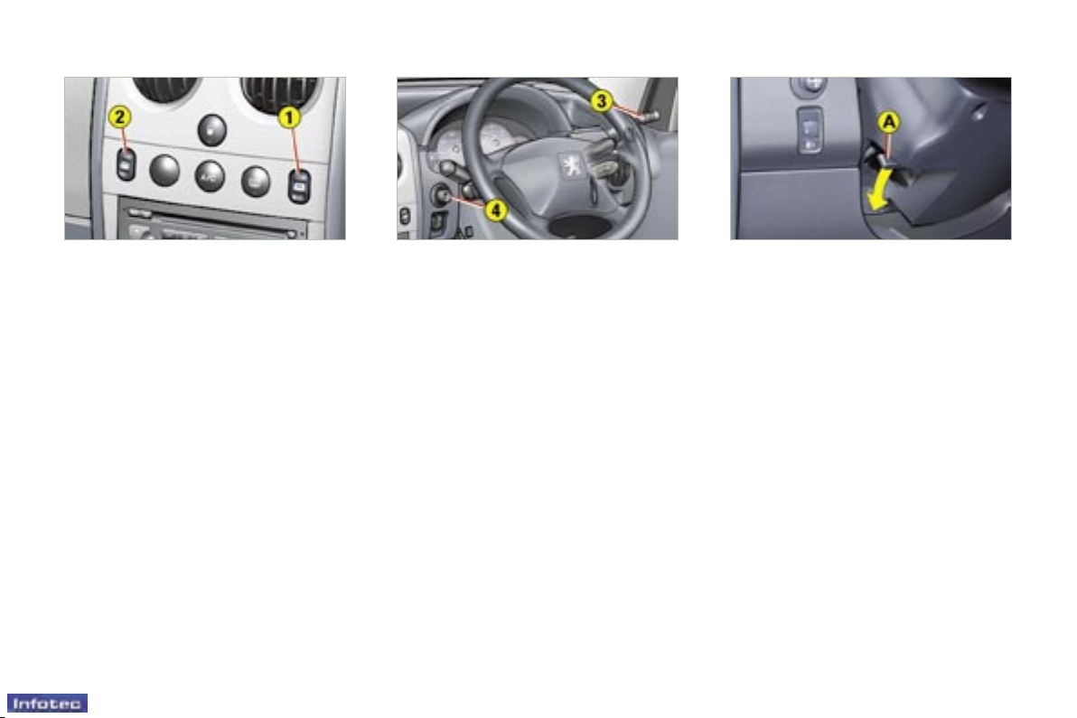
STEERING WHEEL HEIGHT
ADJUSTMENT
F When stationary, push the
control A forwards to unlock the
steering wheel.
F Adjust the height of the steering
wheel.
F Lock it by pulling control A
towards you fully.
ELECTRIC WINDOWS
1 - Driver’s electric window.
2 - Passenger’s electric window.
EXTERIOR MIRRORS
F Move the manual control 3 in all
four directions to adjust.
Electric control for the
passenger’s side mirror
F From the driver’s seat, adjust in
all four directions by operating the
control 4.
Manual mode:
F Press the switch. The window
stops as soon as the switch is
released.
Automatic mode (driver):
F Press and hold the the switch.
One touch completely opens or
closes the window.
: 68 : 69 : 72
01-10-2005

Practical information
100 -
01-10-2005
101
Practical information
-
01-10-2005
ECONOMY MODE FUNCTION
After the engine has stopped, with
the key in the accessories position,
certain functions (windscreen wiper,
electric windows, courtesy lights,
audio equipment, etc.) can only be
used for thirty minutes, to prevent
discharging the battery.
Once the thirty minutes are over, the
message "Economy mode active"
appears on the multifunction display
and the active functions are put on
standby.
BATTERY
To charge the battery using a
battery charger:
- Disconnect the battery,
- Follow the instructions for use given by the battery charger manufacturer,
- Reconnect starting with the negative (-) terminal,
- Check that the terminals and
connectors are clean. If they are
covered with sulphate (white or
greenish deposit), disconnect them
and clean them.
It is advisable to disconnect the
battery if the vehicle is not to be
used for a period of more than
one month.
Never disconnect a terminal
when the engine is running.
Never charge a battery without rst disconnecting the
terminals.
After every reconnection of
the battery, switch on the ignition
and wait 1 minute before starting to
allow the electronic systems to be
initialised. If slight difculties are experienced after this, please contact a
PEUGEOT dealer.
A at battery will prevent the
engine from starting.
To start the vehicle from
another battery:
- Connect the red cable to the positive (+) terminals of the two batteries,
- Connect one end of the green or
black cable to the negative (-) terminal of the slave battery,
- Connect the other end of the green
or black cable to an earth point on
the broken down vehicle as far as
possible from the battery.
Operate the starter, let the engine
run.
Wait for the engine to return to idle,
then disconnect the cables.
101
Practical information
-
01-10-2005
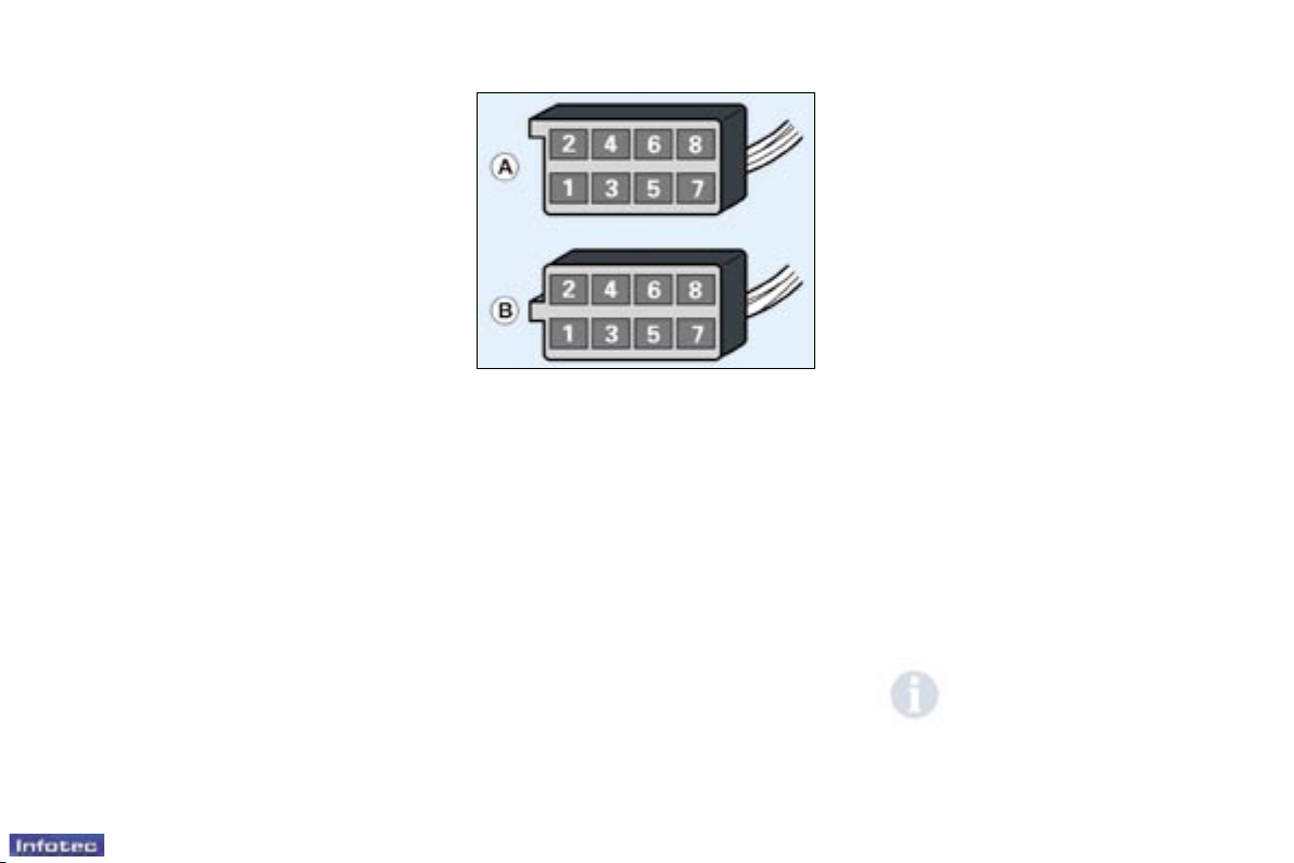
Making the connections
A1 : A2 : - Digital control
(manufacturer).
A3 : - Digital control
(manufacturer).
A4 : - Audio equipment
multiplexing
(manufacturer).
A5 : A6 : (+ve) Accessories
A7 : (+ve) Permanent
A8 : (-ve) Earth
B1 : (+) B2 : (-) B3 : (+) Front right speaker and
tweeter
B4 : (-) Front right speaker and
tweeter
B5 : (+) Front left speaker and
tweeter
B6 : (-) Front left speaker and
tweeter
B7 : (+) B8 : (-) -
FITTING SPEAKERS
The factory-tted equipment allows
the tting of:
- 35 mm diameter tweeters in the
fascia,
- 165 mm diameter speakers in the
front doors.
FITTING AUDIO EQUIPMENT
Your vehicle is equipped with certain
factory-tted audio equipment:
- roof aerial,
- coaxial aerial cable,
- basic interference suppression,
- supply to front speakers and
tweeters,
- two 8-way connectors.
Contact a PEUGEOT
dealer before tting audio
equipment or speakers in
your vehicle.
Practical information
102 -
01-10-2005
103
Practical information
-
01-10-2005
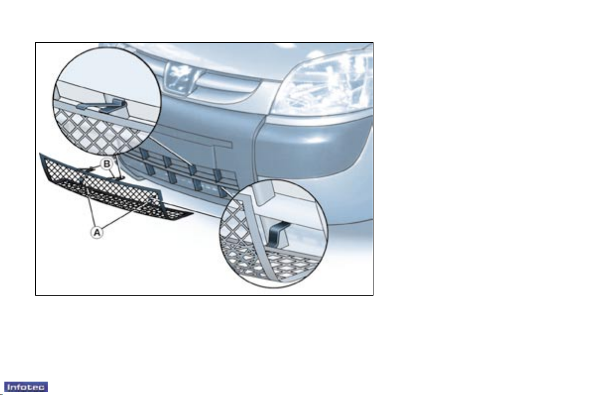
SNOW SCREEN*
The snow screen is installed on the
lower part of the front bumper to
prevent the accumulation of snow at
the radiator cooling fan.
When the snow has cleared
(temperature above 10°C), remove
the snow screen.
* According to country.
FITTING
F Offer up the snow screen facing
the front bumper.
F Put it in place positioning the
lower clips A in the bumper.
F Press the snow screen at each
upper clip B.
REMOVAL
F Press the two upper clips B and
pull the snow screen.
103
Practical information
-
01-10-2005
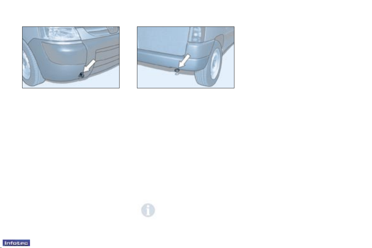
Without lifting (four wheels on the
ground)
You must always use a towbar.
Never use the radiator crossmember.
When towing another vehicle, it must freewheel (gearbox in neutral).
By lifting (two wheels only on the
ground)
It is preferable to lift the vehicle by
the wheels.
TOWING YOUR VEHICLE
From the front or the rear
Attach the towbar to the towing eye.

Practical information
104 -
01-10-2005
105
Practical information
-
01-10-2005
TOWING A TRAILER,
CARAVAN, BOAT, etc.
We recommend the use of original
PEUGEOT towbars that have been
tested and approved from the design
stage of your vehicle and that the
tting of the towbar is entrusted to a
PEUGEOT dealer.
Your vehicle is primarily designed
for transporting people and luggage
but it may also be used for towing a
trailer.
Driving with a trailer subjects the
towing vehicle to more signicant
stress and its driver must be
particularly careful.
Air density decreases with altitude,
thus reducing engine performance.
Above 1000 metres, the maximum
towing load must be reduced by 10%
and so on for every 1000 metres of
altitude.
Driving advice
Distribution of loads: Distribute the
load in the trailer so that the heaviest
items are as close as possible to the
axle and the nose weight approaches
the maximum permitted without
exceeding it.
Cooling: Towing a trailer on a slope
increases the temperature of the
coolant.
As the fan is electrically controlled,
its cooling capacity is not dependent
on the engine speed.
On the contrary, use a high gear to
lower the engine speed and reduce
your speed.
The maximum towing load on a long
slope depends on the gradient and
the outside temperature.
In all cases, pay attention to the
coolant temperature.
If the warning light comes on, stop
the vehicle and switch off the engine
as soon as possible.
Tyres: Check the tyre pressures
of the towing vehicle and of the
trailer, observing the recommended
pressures.
Braking: Towing increases the braking distance.
Lights: Check the electrical signalling on the trailer.
Side wind: Take into acount the increased sensitivity to side wind.
105
Practical information
-
01-10-2005
ACCESSORIES FOR YOUR
PARTNER
A wide choice of accessories recommended by PEUGEOT and original
parts is available through the dealer
network.
These accessories and parts, after
being tested and approved for reliability and safety, are all adapted to
your PEUGEOT vehicle.
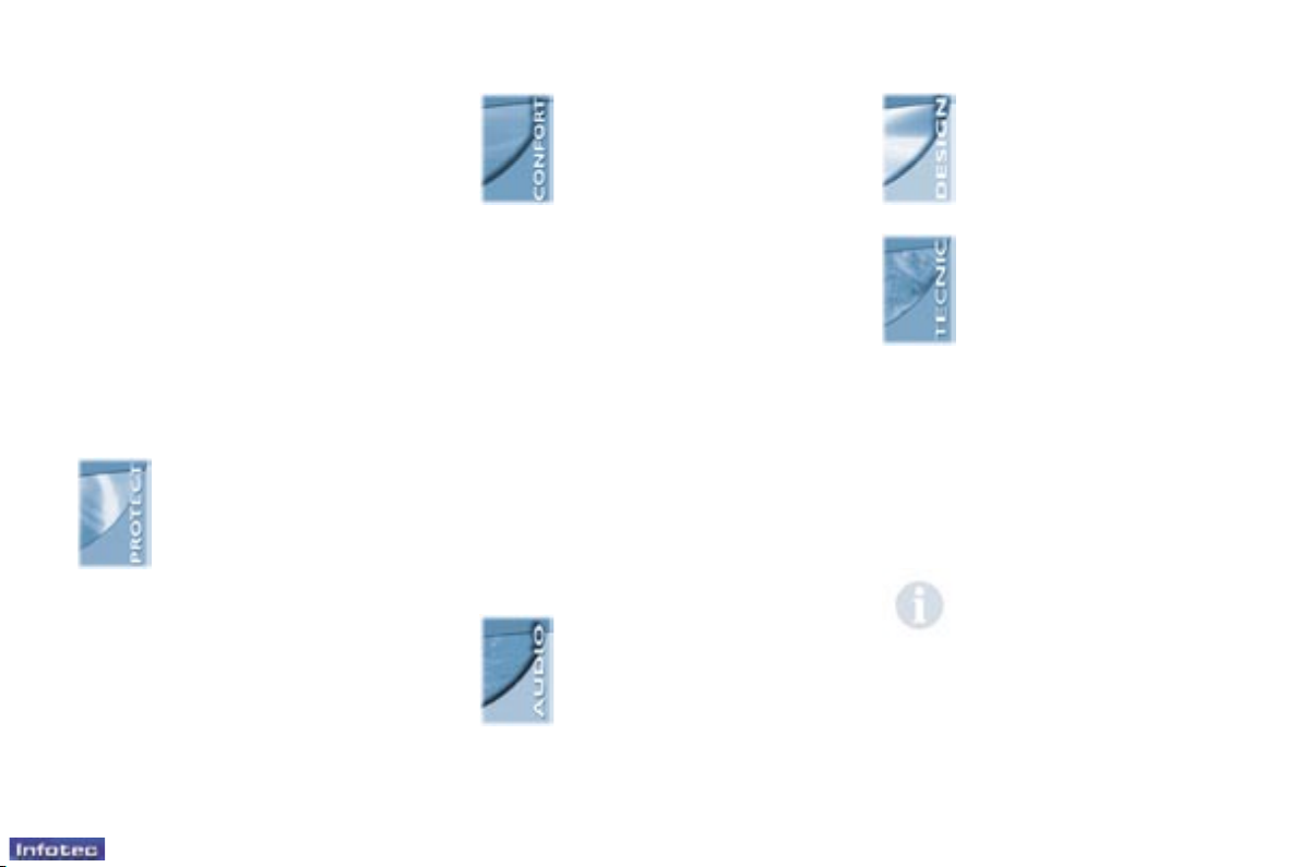
This product range offered by PEUGEOT
Accessories is structured around 5 categories:
- PROTECTION
- TOURING
- IN-CAR TECHNOLOGY
- STYLING
- UNIVERSAL,
it is dedicated to:
The tting of electrical
equipment or accessories
which are not recommended
by PEUGEOT may result in
a failure of your vehicle's
electronic system.
Please note this specic warning.
You are advised to contact a
representative of the Marque to be
shown the range of recommended
equipment and accessories.
"Universal": Screenwash,
interior and exterior
maintenance and cleaning
products...
"Protection": Separation
grille, window protectors,
anti-theft alarm, wheel
locks, parking assistance,
signalling triangle, rst
aid kit, fog lamps, safety
jacket...
"In-Car Technology":
Audio systems, audiotelephone, speakers, CD
changer, navigation system,
telephone console...
"Touring": Rear and side
windows, audio-telephone
console, seat covers compatible with side air bags,
mats, rubber boot carpet,
thermoformed side protec-
tors, low partition interior
grille, luggage net, door deectors,
roof rack, thermoformed interior
protectors, wooden interior ttings,
loading roller, towbar, roof bars,
snow chains, tailgate bicycle carrier,
booster seats and child seats...
Note
To prevent the mat from becoming
caught under the pedals:
- ensure that the mat is positioned
and secured correctly,
- never t one mat on top of
another.
"Styling": Alloy wheels,
door sills, mud aps ...
Technical data
108 -
01-10-2005
109
Technical data
-
01-10-2005
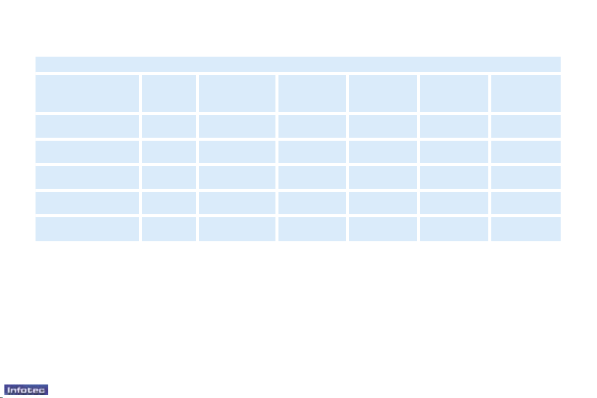
CONSUMPTION
The consumption values presented here correspond to the values communicated at the time of printing. These consumption
values were established in accordance with EC Directive 80/1268 (as amended). They may vary depending on the style
of driving, trafc conditions, weather conditions, the load in the vehicle, the maintenance of the vehicle and the use of the
accessories.
In accordance with EC Directive 80/1268 (as amended) in M.P.G. (litres/100 km)
Engine Gearbox Model codes Version Urban driving Inter-urban Mixed
1.4 litre Manual
GBKFWC
GCKFWC
600 kg
800 kg
28.5 (9.9)
28.5 (9.9)
44.8 (6.3)
44.8 (6.3)
37.6 (7.5)
37.6 (7.5)
1.6 litre Turbo HDI Manual
GB9HWC
GC9HWC
600 kg
800 kg
42.2 (6.7)
42.2 (6.7)
60.1 (4.7)
60.1 (4.7)
52.4 (5.4)
52.4 (5.4)
1.6 litre Turbo HDI Manual
GB9HXC
GC9HXC
600 kg
800 kg
41.5 (6.8)
41.5 (6.8)
61.4 (4.6)
61.4 (4.6)
52.4 (5.4)
52.4 (5.4)
1.9 litre Manual
GBWJYB
GCWJYB
600 kg
800 kg
30.4 (9.3)
30.4 (9.3)
49.6 (5.7)
49.6 (5.7)
40.4 (7.0)
40.4 (7.0)
2 litre Turbo HDI Manual
GBRHYB
GCRHYB
600 kg
800 kg
41.5 (6.8)
40.9 (6.9)
61.4 (4.6)
60.1 (4.7)
47.1 (6.0)
47.1 (6.0)

11
Familiarisation
-
CRUISE CONTROL*
The cruise control has a display on
the instrument panel which indicates
the programmed reference speed.
It enables the vehicle to maintain a
constant speed, programmed by the
driver.
In order to be programmed or
activated, the vehicle speed must
be above 25 mph (40 km/h), with at
least fourth gear engaged.
SPEED LIMITER*
This speed limiter indicates the
status of selection of the function on
the instrument panel and displays the
programmed speed. The minimum
speed which can be programmed is
20 mph (30 km/h).
It prevents the vehicle from exceeding
the speed programmed by the
driver, this function remains active
regardless of any action on the brake
or clutch pedals. On the other hand,
pressing the accelerator pedal to the
point of resistance does not have any
effect. If the driver wishes to exceed
the programmed limit, he must force
the accelerator pedal travel beyond
this point of resistance.
: 76 * According to engine and country.: 78
On vehicles which are tted
with the speed limiter and
cruise control functions,
these functions cannot be
activated simultaneously.
Setting adjustments must be made
when stationary with the engine
running, or while the vehicle is
moving.
01-10-2005
113
Technical data
-
01-10-2005
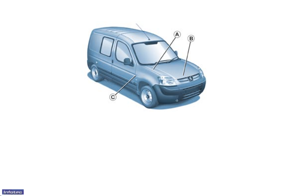
THE IDENTIFICATION FEATURES OF YOUR PARTNER
B. Serial number on the
bodywork (under the
bonnet, on the right-hand
crossmember).
C. Tyres and paint colour
reference.
The label C on the driver's door pillar,
near the hinges, gives:
- the wheel and tyre sizes,
- the tyre pressures: (tyre pressure
checks must be carried out cold,
at least every month),
- the paint colour reference.
A. Manufacturer's plate (under
the bonnet, on the front right
wing).

Familiarisation
12 -
13
Familiarisation
-
HEATING
AIR CONDITIONING
N° Symbol Function
1 Air ow adjustment.
2
Air ow adjustment
and air intake
control.
3
Temperature
adjustment.
4
Air distribution
adjustment.
N° Symbol Function
1
Air conditioning
control.
2
Air ow adjustment
and air intake
control.
3
Temperature
adjustment.
4
Air distribution
adjustment.
: 40
: 42
01-10-2005
13
Familiarisation
-
RECOMMENDED INTERIOR SETTINGS
I require...
Heating or Manual air conditioning
Air distribution Air ow
Air recirculation /
Intake of exterior air
Temperature Manual AC
HOT
COLD
DEMISTING
DE-ICING
01-10-2005

Familiarisation
14 -
15
Familiarisation
-
FRONT FITTINGS
1. Storage compartments in the
doors
A. Bottle holder.
B. Can holder.
C. Storage compartment.
2. Overhead storage with map
reading light
3. Courtesy light
4. Sun visor
5. Glove box
6. Lighter
7. Removable ashtray
8. 12 v accessories socket
9. Storage drawer
: 71
01-10-2005
15
Familiarisation
-
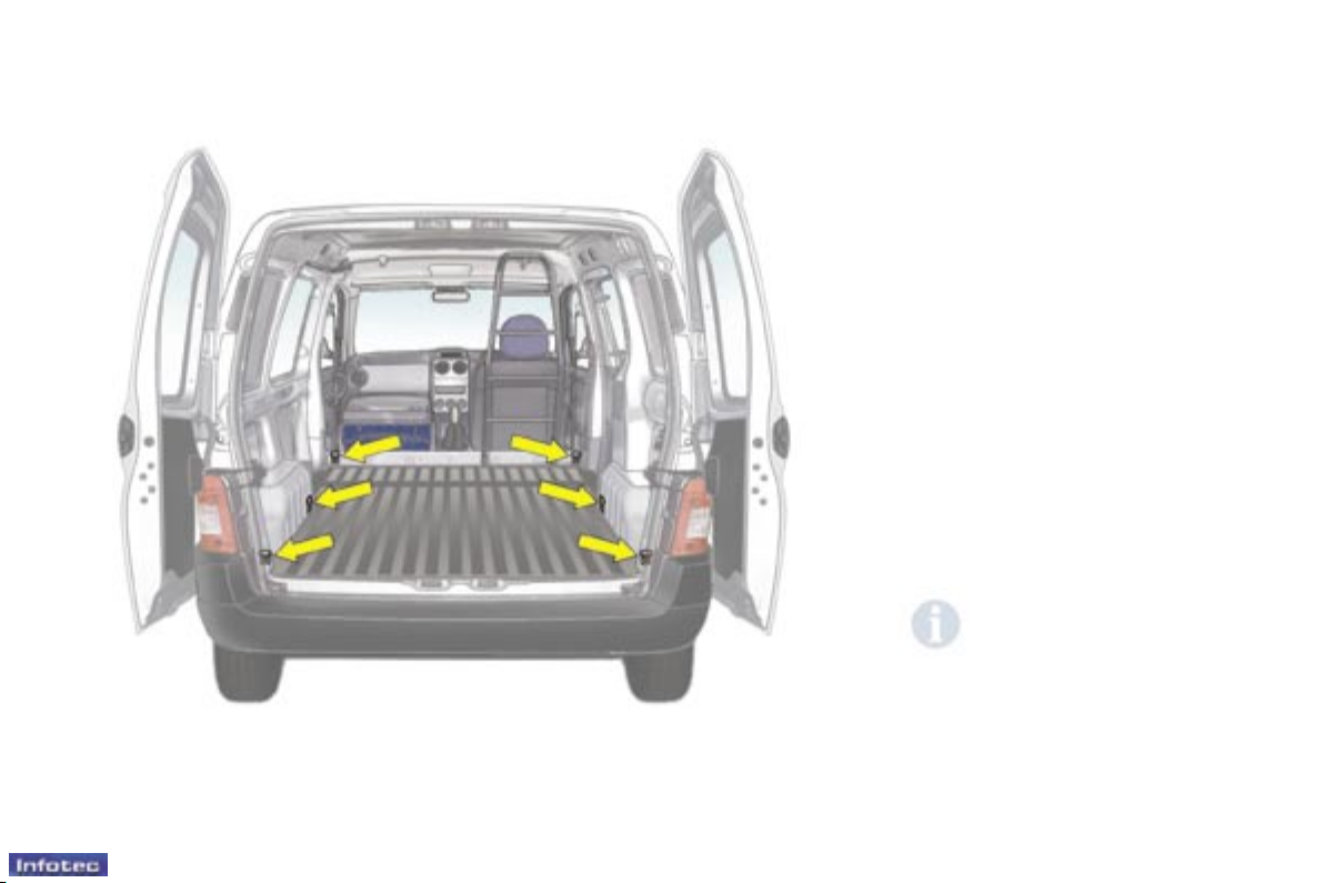
STOWING RINGS
Use the 6 stowing rings located on
the boot oor to secure your loads.
You can use suitable load retainers
(half-height partitions, grille, etc...)
supplied by your PEUGEOT dealer.
For greater safety, always
secure the loads transported
rmly.
: 73
01-10-2005
Familiarisation
16 -
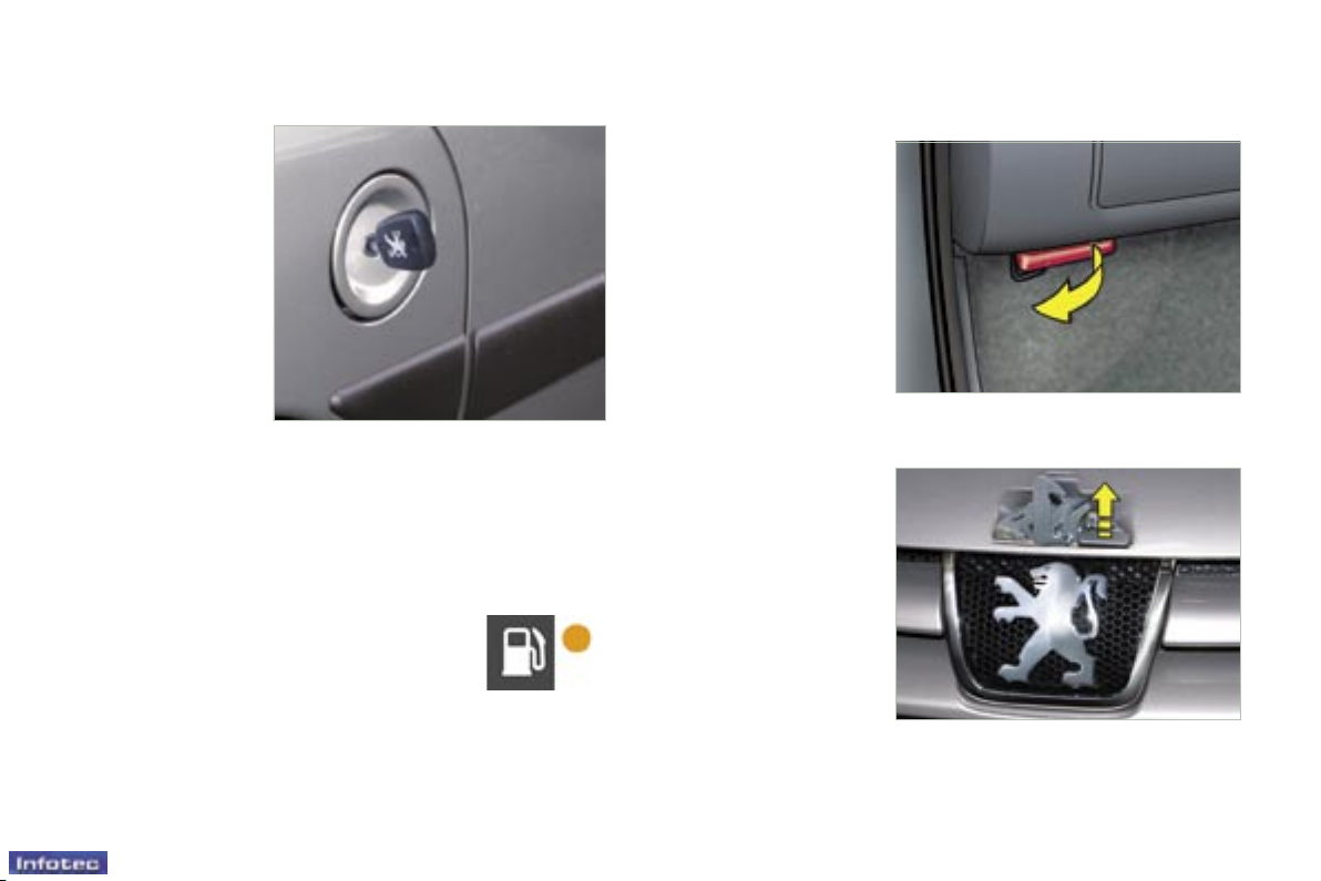
FILLING WITH FUEL
This operation must be carried out
with the engine switched off.
F Insert the key then turn it to the
left.
F Remove the cap.
An indication shows which type of
fuel to use.
When you ll your tank, do not
continue after the third cut-off of
the pump. This could cause a
malfunction.
The capacity of the tank is
approximately 55 litres for petrol
engines and 60 litres for Diesel
engines.
From the time this light comes on,
you have enough fuel left to cover
approximately 30 miles (50 km).
Outside the vehicle: Lift the control,
raise the bonnet and secure the strut
to keep the bonnet open.
OPENING THE BONNET
Inside the vehicle: Pull the control
on the left-hand side, under the
fascia panel.
Note: the right-hand sliding side door
cannot be opened while the fuel tank
cap is removed.
Low fuel level
warning light
: 62: 62
01-10-2005
Instruments, controls and displays
18 -
01-10-2005
19
Instruments, controls and displays
-
01-10-2005
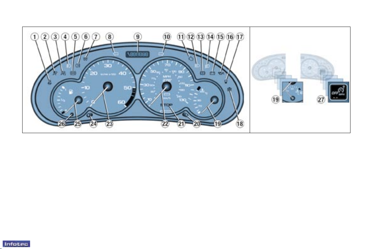
1. Seat belt not fastened warning
light*
2. Passenger air bag disarmed
warning light*
3. Front and side air bags warning
light
4. Front fog lamps indicator light
5. Anti-lock braking system (ABS)
warning light
6. Rear fog lamp indicator light
7. Diesel pre-heat warning light
8. Left hand direction indicator
9. Total distance recorder, service
indicator and engine oil level
indicator
10. Right hand direction indicator
11. Emission control system
warning light
12. Main beam headlamps indicator
light
13. Handbrake, low brake uid
level and electronic brake force
distribution warning light
14. Dipped beam headlamps
indicator light
15. Battery charge warning light
16. Engine oil pressure and
temperature warning light
17. Water in diesel lter warning
light
18. Low coolant level warning light
19. Coolant temperature indicator
20. Total distance recorder button
21. Central (STOP) warning light
22. Speedometer**
23. Rev counter
24. Lighting rheostat button
25. Fuel level indicator
26. Low fuel level warning light
27. Speed limiter/cruise control
display***
INSTRUMENT PANEL: PETROL - DIESEL
* According to country.
** Version indicating kilometres,
according to country.
*** According to model.
Instruments, controls and displays
22 -
01-10-2005
23
Instruments, controls and displays
-
01-10-2005
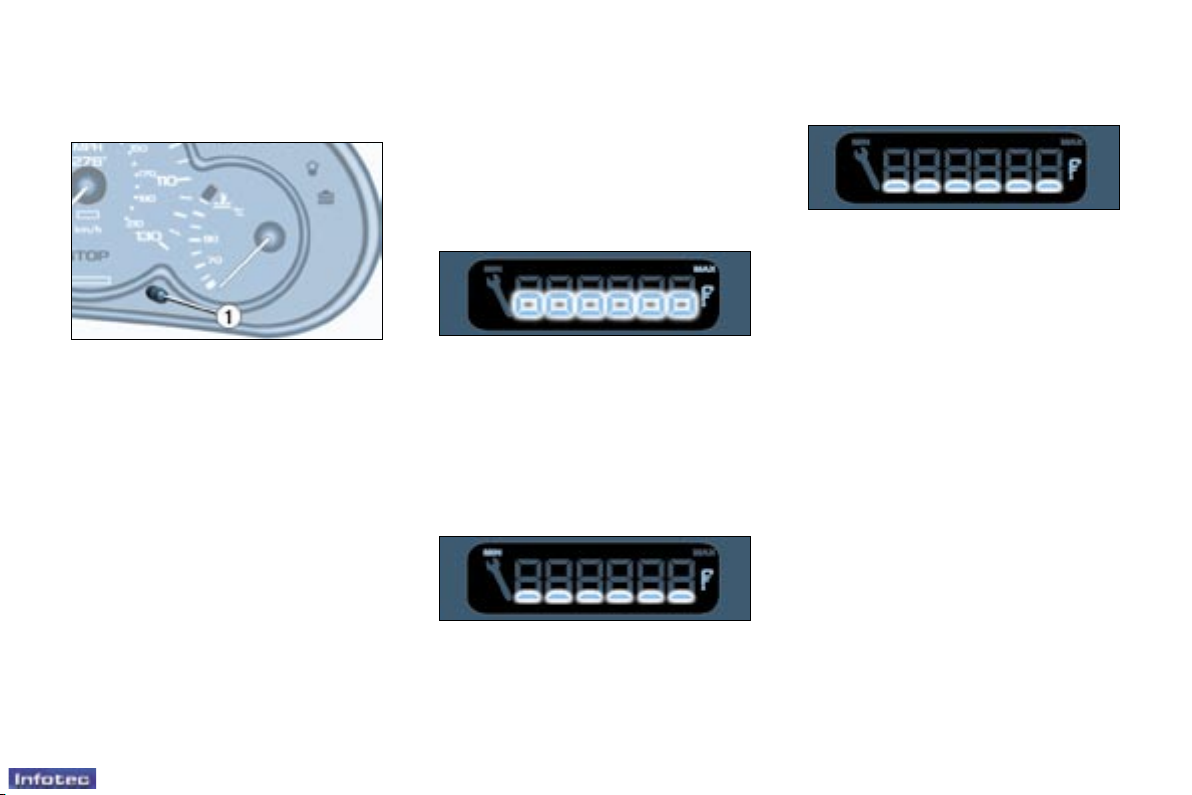
Service indicator
This is a visual reminder of when
the next service is due. This service
is to be carried out according to the
manufacturer's servicing schedule.
5 seconds after the ignition is
switched on, the total distance recorder resumes normal operation
and the display shows the total or trip
distances.
The distance remaining before
the next service is less than
500 miles (1,000 km).
Example: 400 miles (900 km) remain
before the next service is due.
When switching on the ignition and
for 5 seconds, the display shows:
5 seconds after the ignition is
switched on, the total distance recorder resumes normal operation
and the symbol remains lit.
This indicates that a service should
be carried out shortly. The display
shows the total or trip distances.
The service is overdue.
Each time the ignition is switched on
and for 5 seconds, the symbol and
the excess distance ash.
Example: the service is overdue by
300 miles/km. The service should be
carried out very shortly.
When the ignition is switched on and
for 5 seconds, the display shows:
5 seconds after the ignition is
switched on, the total distance recorder resumes normal operation
and the symbol remains lit. The
display shows the total or trip distances.
Note: the service spanner lights
if the two-year interval has been
exceeded.
INSTRUMENT PANEL
DISPLAY
After switching on the ignition, three
functions are shown in succession:
- service indicator,
- engine oil level indicator (Diesel),
- total distance recorder/total and trip
distances.
Note: the total and trip distances are
displayed for 30 seconds when the
ignition is switched off, on opening
the driver's door, as well as on
locking and unlocking the vehicle.
Example: 4,800 miles/km remain
before the next service is due. When
the ignition comes on and for 5 seconds the display indicates:
Operation
As soon as the ignition is switched
on and for 5 seconds, the spanner
symbolising ''service operation'' is lit.
The trip recorder display shows the
distance remaining (in round gures)
before the next service.
23
Instruments, controls and displays
-
01-10-2005
Engine oil level indicator
(Diesel)
When the ignition is switched on,
the engine oil level is indicated for
approximately 10 seconds, after the
service information.
Flashing of the six squares and
displaying of "max" indicate a
surplus of oil which could damage
the engine.
If the surplus of oil is conrmed by
a check using the dipstick, contact a
PEUGEOT dealer without delay.
Your PEUGEOT dealer carries out
this operation after each service. The
reset procedure is as follows:
- Switch off the ignition.
- Press and hold button 1.
- Switch on the ignition.
The display begins a 10 second
countdown.
- Keep button 1 pressed for
10 seconds.
The display shows [=0] and the
service symbol disappears.
Flashing of the six segments and
displaying of "min" indicate a lack of
oil which could damage the engine.
If the lack of oil is conrmed by a
check using the dipstick, it is essential that the level is topped up.
Flashing of the six segments indicates a malfunction of the oil level
indicator.
There is a risk of damage to the engine.
Contact a PEUGEOT dealer.
The level read on the dipstick or on
the indicator will only be correct if
the vehicle is on level ground and
the engine has been off for more
than 15 minutes.
Resetting the service indicator
Surplus of oil
Lack of oil
Oil level indicator fault
Instruments, controls and displays
24 -
01-10-2005
25
Instruments, controls and displays
-
01-10-2005
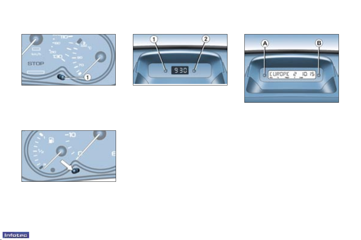
DISPLAY A
This displays the following
information:
- the time,
- the date,
- the audio system displays,
- a door check (e.g.: ''left front door
open''),
- warning messages (e.g. ''remote
control battery at'') or information
messages (e.g. ''economy mode
active''), displayed temporarily.
Briey pressing button 1 alternates
between the total and trip distance
displays.
To reset the trip recorder to zero,
when it is displayed press button 1
until zeros appear.
Total distance recorder
With the lights on, press the button
to vary the intensity of the lighting of
the instruments and controls. When
the lighting reaches the minimum (or
maximum) setting, release the button
then press it again to increase (or
reduce) the brightness.
As soon as the lighting is of the required brightness, release the button.
Lighting rheostat
CLOCK
Button 1 : hour adjustment
Button 2 : minute adjustment
Press and hold the button for rapid
advance.

25
Instruments, controls and displays
-
01-10-2005
Adjusting the parameters
display A
Press and hold button A for two
seconds to access the settings; the
data ashes, indicating it is ready to
be modied.
Then, each press of button A scrolls
through the various data in the
following order:
- language of information displayed,
- hours (12 then 24 hour mode),
- minutes,
- year,
- month,
- day.
Pressing button B alters the value of
the parameter selected. Press and
hold for rapid advance (return to start
after the last possible value).
After 7 seconds with no action,
the standard display returns; the
modied data is now recorded.
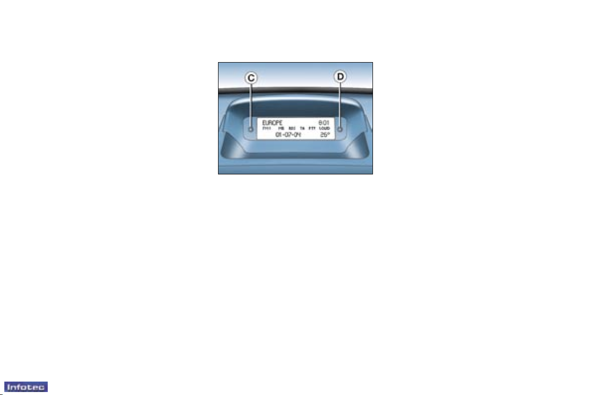
MONOCHROME DISPLAY B
This enables the following information
to be displayed:
- the time,
- the date,
- the outside temperature (this
ashes accompanied by the
message "Ice alert"),
- the radio displays,
- the status of the doors. The display
shows you, by means of a graphic,
whether a door is open,
- the warning messages (e.g.
''battery charge fault'') or
information messages (e.g. "fuel
level low''), displayed temporarily,
can be cleared by pressing button
C or D,
- the trip computer.
Setting the parameters screen B
Press button C for two seconds to
access the settings. The information
ashes to show it is ready to be
modied.
Then, individual presses on button C
allow you to scroll through the various
data in the following sequence:
- language in which the information
is displayed,
- unit of distance (kms or miles),
- unit of temperature (degrees
Celsius or Fahrenheit),
- time format (12 then 24 hour
mode),
- hour,
- minutes,
- year,
- month,
- day.
Pressing button D allows you to
change the information selected.
Maintain the pressure for rapid
scrolling.
After 7 seconds without operation,
the screen returns to the normal
display and the modied data is
recorded.

Instruments, controls and displays
24 -
01-10-2005
25
Instruments, controls and displays
-
01-10-2005
DISPLAY A
This displays the following
information:
- the time,
- the date,
- the audio system displays,
- a door check (e.g.: ''left front door
open''),
- warning messages (e.g. ''remote
control battery at'') or information
messages (e.g. ''economy mode
active''), displayed temporarily.
Briey pressing button 1 alternates
between the total and trip distance
displays.
To reset the trip recorder to zero,
when it is displayed press button 1
until zeros appear.
Total distance recorder
With the lights on, press the button
to vary the intensity of the lighting of
the instruments and controls. When
the lighting reaches the minimum (or
maximum) setting, release the button
then press it again to increase (or
reduce) the brightness.
As soon as the lighting is of the required brightness, release the button.
Lighting rheostat
CLOCK
Button 1 : hour adjustment
Button 2 : minute adjustment
Press and hold the button for rapid
advance.
25
Instruments, controls and displays
-
01-10-2005
Adjusting the parameters
display A
Press and hold button A for two
seconds to access the settings; the
data ashes, indicating it is ready to
be modied.
Then, each press of button A scrolls
through the various data in the
following order:
- language of information displayed,
- hours (12 then 24 hour mode),
- minutes,
- year,
- month,
- day.
Pressing button B alters the value of
the parameter selected. Press and
hold for rapid advance (return to start
after the last possible value).
After 7 seconds with no action,
the standard display returns; the
modied data is now recorded.
MONOCHROME DISPLAY B
This enables the following information
to be displayed:
- the time,
- the date,
- the outside temperature (this
ashes accompanied by the
message "Ice alert"),
- the radio displays,
- the status of the doors. The display
shows you, by means of a graphic,
whether a door is open,
- the warning messages (e.g.
''battery charge fault'') or
information messages (e.g. "fuel
level low''), displayed temporarily,
can be cleared by pressing button
C or D,
- the trip computer.
Setting the parameters screen B
Press button C for two seconds to
access the settings. The information
ashes to show it is ready to be
modied.
Then, individual presses on button C
allow you to scroll through the various
data in the following sequence:
- language in which the information
is displayed,
- unit of distance (kms or miles),
- unit of temperature (degrees
Celsius or Fahrenheit),
- time format (12 then 24 hour
mode),
- hour,
- minutes,
- year,
- month,
- day.
Pressing button D allows you to
change the information selected.
Maintain the pressure for rapid
scrolling.
After 7 seconds without operation,
the screen returns to the normal
display and the modied data is
recorded.
38 -
Ventilation
01-10-2005
39-
Ventilation
01-10-2005
39-
Ventilation
01-10-2005
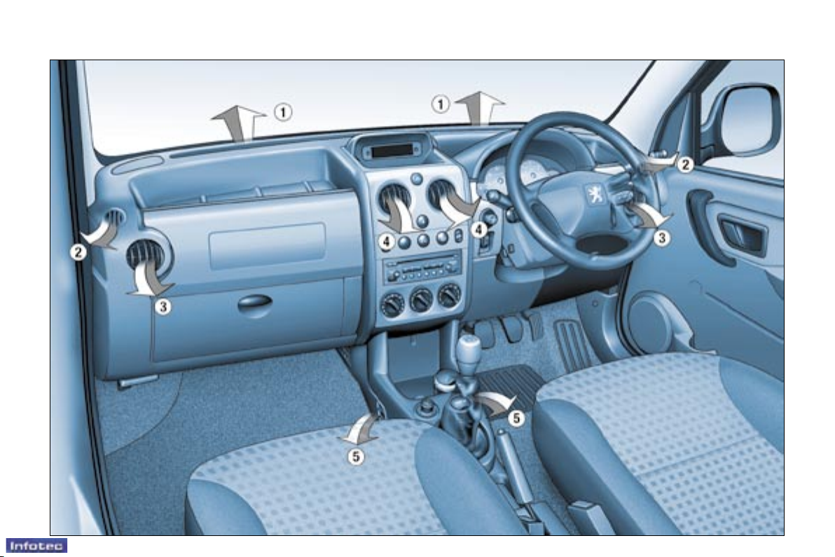
VENTILATION
1. Windscreen de-icing or
demisting vents.
2. Front window de-icing or
demisting vents.
3. Side vents.
4. Centre vents.
5. Air outlets to front footwells.
The air conditioning system does not
contain chlorine and does not present
any danger to the ozone layer.
Operate the air conditioning system
for 5 to 10 minutes, once or twice a
month, to keep it in perfect working
order.
The water created by the air
conditioning condensation is
discharged via an opening provided
for this purpose. Therefore, a puddle
of water may form underneath the
vehicle when stationary.
If the system does not produce cold
air, do not use it and contact your
PEUGEOT dealer.
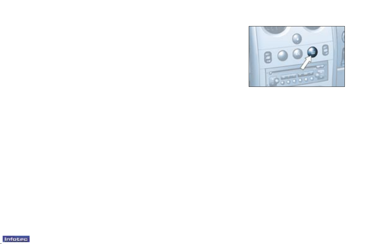
De-icing the rear screen and
mirrors
With the engine running, pressing
the control de-ices the rear screen
and mirrors.
It switches off automatically after
approximately twelve minutes.
Pressing the control again switches
the de-icing system on again for
twelve minutes.
It is possible to switch off the de-icing
by pressing the control before the
twelve minutes have elapsed.
Advice on operation
Select the air distribution most suited
to your requirements and the climatic
conditions.
Gradually adjust the temperature
setting for your comfort.
Position the air control in the ''Outside
Air'' position.
For perfectly even air distribution,
take care not to obstruct the exterior
air intake grille and the vents.
Check that the passenger compartment lter is in good condition.
When the engine is cold, to prevent
too great a distribution of cold air,
the ventilation will increase to its
optimum level gradually.
In order to be effective, the air
conditioning (A/C button), should
only be used with the windows
closed.
If the interior temperature remains
very high following a prolonged
period parked in the sun, do not
hesitate to ventilate the passenger
compartment for a few minutes.
 Loading...