

Page 1

Troubleshooting
RENR2696-01
March 2005
1104E and
R F11 -U p ( Engine)
RH11-Up (
R K 11- U p ( Engine)
VK11-Up (Engine)
Engine)
1106E Engines
Page 2
i01658146
Important Safety Information
Most accidents t
basic safety rules or precautions. An accident can often be avoided by recognizing potentially hazardous
situations before an accident occurs. A person must be alert to potential hazards. This person should also
have the necess
Improper operation, lubrication, maintenance or repair of this product can be dangerous and
could result in injury or death.
Do not operate o
read and understood the operation, lubrication, maintenance and repair information.
Safety precautions and warnings are provided in this manual and on the product. If these hazard warnings
are not heeded
The hazards are identified by the “Safety Alert Symbol” and followed by a “Signal Word” such as
“DANGER”, “WARNING” or “CAUTION”. The Safety Alert “WARNING” label is shown below.
The meaning of this safety alert symbol is as follows:
Attention! Be
The message that appears under the warning explains the hazard and can be either written or pictorially
presented.
Operations th
this publication.
hat involve product operation, maintenance and repair are caused by failure to observe
ary training, skills and tools to perform these functions properly.
r perform any lubrication, maintenance or repair on this product, until you have
, bodily injury or death could occur to you or to other persons.
come Alert! Your Safety is Involved.
at may cause product damage are identified by “NOTICE” labels on the product and in
Perkins cannot anticipa te e ver y p os sible c irc u mstance t hat m ight invol ve a pote n ti al hazard .
The warnings
proc edure, work me thod or ope rating technique tha t is not s pecific ally rec ommended by Perkins
is used, you must satisfy yourself that it is safe for you and for others. You should also ensure that
the product w
repair procedures that you choose.
The information, specifications, and illustrations in this publication are on the basis of information that
was availabl
measurements, adjustments, illustrations, and other items can change at any time. These changes can
affect the service that is given to the product. Obtain the complete and most current information before you
s t ar t any jo
in this publication and on the product are, therefore, not all inclusive. If a tool,
ill not be damaged or be made unsafe by the operation, lubrication, maintenance or
e at the time that the publication was written. The specifications, torques, pressures,
b . Perkins dea le rs hav e t he m os t c ur r en t i nfo rm ati on a va il abl e.
When replacement parts are required for this
product Perkins re comme nds usi ng Perkins
e ment parts or parts w ith equiva lent
re pl ac
specifications including, but not limited to, physical dimensions, type, strength and material.
Failure to heed this warning can lead to premature failures, product damage, personal injury or
death.
Page 3

RENR2696-01 3
Table of Contents
Table of Contents
Troubleshooting Section
Electronic Troubleshooting
System Overview .................................................... 5
Glossary .................................................................. 9
Electronic Service Tools ........................................ 12
Diagnostic Codes .................................................. 13
Indicator Lamps .................................................... 15
Replacing the ECM ............................................... 18
Self-Diagnostics .................................................... 19
Sensors and Electrical Connectors ....................... 20
Engine Wiring Information .................................... 26
Programming Parameters
Programming Parameters ..................................... 32
Factory Passwords ............................................... 32
Flash Programming .............................................. 32
System Configuration Parameters
System Configuration Parameters ........................ 34
Troubleshooting without a Diagnostic Code
Alternator Noise (Noisy Operation) ....................... 35
Alternator Will Not Charge (Charging Problem) .... 35
Battery .................................................................. 35
Can Not Reach Top Engine RPM ......................... 36
Coolant in Engine Oil ............................................ 38
Coolant Temperature Is Too High ......................... 39
ECM Will Not Accept Factory Passwords ............. 40
ECM Will Not Communicate with Other Systems or
Display Modules .................................................. 40
Electronic Service Tool Will Not Communicate with
ECM .......................... .......................................... 40
Engine Cranks but Will Not Start .......................... 41
Engine Has Early Wear ........................................ 43
Engine Misfires, Runs Rough or Is Unstable ........ 43
Engine Oil in Cooling System ............................... 46
Engine Speed Does Not Change .......................... 46
Engine Stalls at Low RPM .................................... 47
Engine Vibration ................................................... 48
Engine Will Not Crank ........................................... 49
Excessive Black Smoke ........................................ 50
Excessive Engine Oil Consumption ...................... 51
Excessive Valve Lash ........................................... 52
Excessive White Smoke ....................................... 53
Intake Air Temperature Is Too High ...................... 54
Intermittent Engine Shutdown ............................... 55
Intermittent Low Power or Power Cutout .............. 56
Low Engine Oil Pressure ...................................... 58
Low Power/Poor or No Response to Throttle ....... 59
Mechanical Noise (Knock) in Engine .................... 61
Noise Coming from Cylinder ................................. 61
Poor Acceleration or Response ............................ 62
Troubleshooting with a Diagnostic Code
CID 0041 FMI 03 8v Sensor Power Supply, Voltage
More Than Normal .............................................. 64
CID 0041 FMI 04 8v Sensor Power Supply, Voltage
Less Than Normal ............................................... 64
CID 0091 FMI 02 Throttle Demand Sensor Erratic Or
Intermittent .............. ............................................ 6
CID 0091 FMI 03 Throttle Demand Sensor Open
Circuit Or Shorted High ....................................... 65
CID 0091 FMI 04 T
Low ..................................................................... 65
CID 0091 FMI 08 Throttle Demand Sensor Abnormal
Signal .................................................................. 66
CID 0091 FMI 12 Throttle Demand Sensor Out Of
Calibration ....................................... .................... 66
CID 0100 FMI 03
Circuit Or Shorted High ....................................... 66
CID 0100 FMI 04 Engine Oil Pressure Sensor
Shorted Low ........................................................ 67
CID 0100 FMI 10 Engine Oil Pressure Sensor, Power
Supply Open Circuit ............................................ 67
CID 0102 FMI 03
Open Circuit Or Shorted High ............................. 67
CID 0102 FMI 04 Intake Manifold Pressure Sensor
Shorted Low ........................................................ 68
CID 0102 FMI 10 Intake Manifold Pressure Sensor
Power Suppl y Open Circuit ................................. 68
CID 0105 FMI 03
Sensor Open Circuit Or Shorted High ................. 69
CID 0105 FMI 04 Intake Manifold Temperature
Sensor Shorte
CID 0110 FMI 03 Engine Coolant Temperature
Sensor Open Circuit Or Shorted High ................. 69
CID 0110 FMI 04
Sensor Shorted Low ........................................... 70
CID 0174 FMI 02 Fuel Temperature Sensor Erratic,
Intermittent
CID 0247 FMI 09 J1939 Datalink, Abnormal
Update ................................................................ 71
CID 0253 FMI 02
CID 0262 FMI 03 5v Sensor Power Supply, Voltage
More Than Normal .............................................. 71
CID 0262 FMI 04
Less Than Normal ............................................... 72
CID 0266 FMI 02 Incorrect Crank-without-inject
inputs .................................................................. 72
CID 0320 FMI 02 Speed And Timing Sensor
Intermittent Loss Of Signal .................................. 73
CID 0320 FMI 11
Signal .................................................................. 73
CID0342FMI02SpeedAndTimingSensorNo.2
Intermittent
CID 0774 FMI 02 Throttle Demand Sensor No.2
Erratic Or Intermittent .......................................... 74
CID 0774 FMI 03
Open Circuit Or Shorted High ............................. 74
CID 0774 FMI 04 Throttle Demand Sensor No.2
Shorted Low ........................................................ 7
CID 0774 FMI 08 Throttle Demand Sensor No.2
Abnormal Signal .................................................. 75
CID 0774 FMI 12
Of Calibration ...................................................... 75
CID 1627 FMI 03 Fuel Injection Pump Relay Did Not
Turn Off ............................................................... 76
CID 1684 FMI 00 Fuel Injection Pump, Fuel
Temperature More Than Normal ......................... 76
CID 1684 FMI 02
Failure ................................................................. 77
hrottle Demand Sensor Shorted
Engine Oil Pressure Sensor Open
Intake Manifold Pressure Sensor,
Intake Manifold Temperature
d Low ........................................... 69
Engine Coolant Temperature
.......................................................... 70
Incorrect ECM Software ........... 71
5v Sensor Power Supply, Voltage
Speed And Timing Sensor Loss Of
Signal ............................................... 73
Throttle Demand Sensor No.2
Throttle Demand Sensor No.2 Out
Fuel Injection Pump, Software
4
5
Page 4

4 RENR2696-01
Table of Contents
CID 1684 FMI 03 Fuel Injection Pump, Fuelling
Fault .................................................................... 77
CID 1684 FMI 04 Fuel Injection Pump, Supply
Voltage Fault ....................................................... 77
CID 1684 FMI 05 F
Width ................................................................... 78
CID 1684 FMI 07 Fuel Injection Pump, Mechanical
Fault .................................................................... 78
CID 1684 FMI 08 Fuel Injection Pump, Crankshaft
Reference Faul t .................................................. 79
CID 1684 FMI 09
Fault .................................................................... 80
CID 1684 FMI 10 Fuel Injection Pump, Fuel Shutoff
Signal Error ......................................................... 8
CID 1684 FMI 11 Fuel Injection Pump, Internal
Sensor Fault ........................................................ 81
CID 1684 FMI 12
Failure ................................................................. 81
CID 1684 FMI 14 Fuel Injection Pump, No
Communicatio
CID 1743 FMI 02 Engine Speed Mode Selection
Switch State, Invalid State .................................. 83
CID 1894 FMI 02
Switch State, Invalid State .................................. 83
CID 1895 FMI 02 Set Speed Control Speed Toggle
Switch, Inval
uel Injection Pump, Invalid Pulse
Fuel Injection Pump, CAN
Fuel Injection Pump, Device
ns ................................................. 82
Set Speed Control Disengage
id State ............................................ 83
Engine Temperature Sensor Open or Short Circuit -
Test ................................................................... 171
Fuel Injection Pump Circuit - Test ....................... 178
Indicator Lamp Circuit - Test ............................... 195
Mode Selection
Set Speed Circuit - Test ...................................... 204
Throttle Switch Circuit - Test ............................... 212
Circuit - Test .............................. 198
Index Section
Index ................................................................... 221
0
Troubleshooting with an Event Code
Event Codes ........................................................ 85
E015 High Engine Coolant Temperature Derate .. 85
E016 High Engine Coolant Temperature
Shutdown ............................................................ 85
E017 High Engine Coolant Temperature
Warning ............................................................... 85
E025 High Intak
E027 High Intake Air Temperature Warning ......... 86
E040 Low Engine Oil Pressure Shutdown ............ 86
E054 High Fuel T
E056 High Fuel Temperature Warning .................. 88
E100 Low Engine Oil Pressure Warning ............... 89
E190 Engine Ove
E442 Engine Failed to Stop with a No-Fuel
Command ........................................................... 90
E883 Engine Fai
Disengaged ......................................................... 91
Diagnostic Fun
5 Volt Engine Pressure Sensor Supply Circuit -
Test ..................................................................... 92
Air Inlet Heate
Analog Throttle Position Sensor Circuit - Test .... 104
CAN Data Link Circuit - Test ................................ 113
Data Link Circu
Digital Throttle Position Sensor Circuit - Test ..... 126
Electrical Connectors - Inspect ........................... 135
Electrical Powe
Engine Oil Level Switch Circuit - Test ................. 152
Engine Pressure Sensor Open or Short Circuit -
Test ................................................................... 157
Engine Speed/Timing Sensor Circuit - Test ........ 164
e Air Temperature Derate ............ 86
emperature Derate .................... 87
rspeed Warning ........................ 90
led To Stop When Fuel Solenoid
ctional Tests
r Circuit - Test ................................. 99
it - Test ......................................... 118
r Supply Circuit - Test ................. 146
Page 5

RENR2696-01 5
Troubleshooting Section
Troubleshooting Section
Electronic Troubleshooting
i01798100
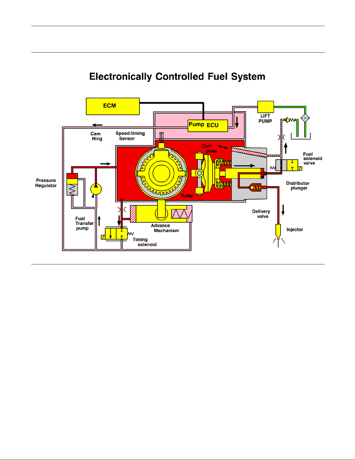
System Overview
System Opera
The 1104 models RF, RH, RK and 1106 model VK
engines were
engines include an Electronic Control Module (ECM),
a fuel injection pump that is electronically controlled,
and a collect
controls the engine operating parameters through
the software within the ECM and the inputs from the
various sen
that control the engine operation. The parameters
include all of the operating maps and customer
selected p
designed for electronic control. The
ion of engine sensors. The ECM
sors. The software contains parameters
arameters.
tion
Page 6
6 RENR2696-01
Troubleshooting Section
Electronic Controls
Illustration 1
g00908788
Page 7
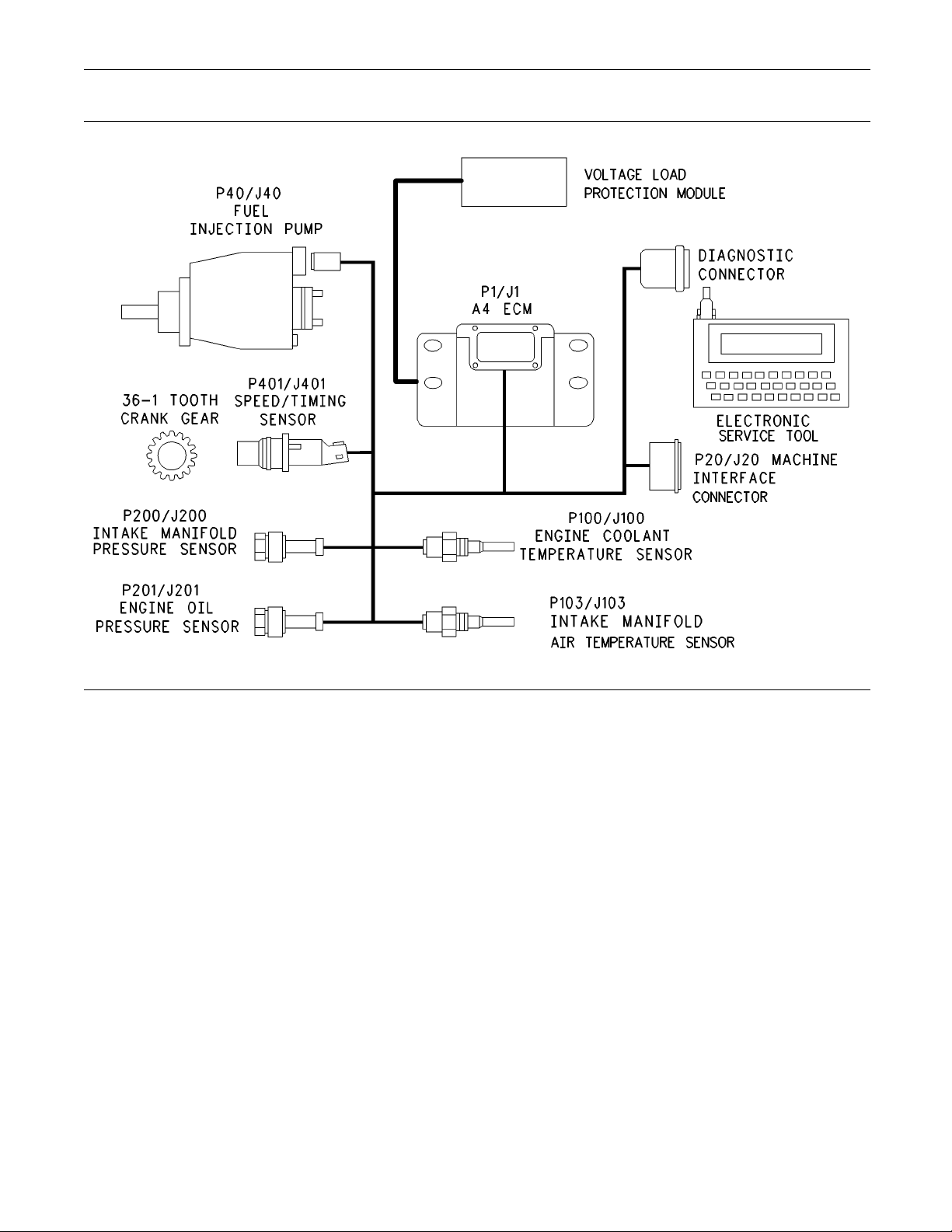
RENR2696-01 7
Troubleshooting Section
Illustration 2
The e lectronic system consists of the Electronic
Control Module (ECM), the engine sensors, and the
Machine Interface Connector (MIC). The ECM is the
computer. The personality module is the software
for the computer. The personality module contains
the operating maps. The operating maps define the
following characteristics of the engine:
Horsepower
•
Torque curves
•
Engine speed (rpm)
•
Engine Governor
The electronic controls determine the injection
timing and the amount of fuel that is delivered to the
cylinders. These decisions are based on the actual
conditions and the desired conditions at any given
time.
g00954204
The governor compares the desired engine speed to
the actual engine speed. The actual engine speed is
determined through the crankshaft position sensor. If
the desired engine speed is greater than the actual
engine speed, the governor injects more fuel in order
to increase engine speed.
Timing Considerations
Once the governor has determined the amount of
fuel that is required, the governor must determine
the timing of the fuel injection. Fuel injection timing is
determined by the ECM after considering input from
the following components:
Engine coolant temperature sensor
•
The sensor for the intake manifold air temperature
•
The sensor for the intake manifold pressure
•
Page 8

8 RENR2696-01
Troubleshooting Section
At start-up, the ECM determines the top dead
center positio
speed/timing sensor in the fuel injection pump.
The ECM decides when fuel injection should occur
relative to th
provides the signal to the fuel injection pump spill
valve which stops fuel flow to the low pressure
side. The ECM
injector nozzles at the desired time. The ECM adjusts
timing for the best engine performance, the best fuel
economy and
Actual timing cannot be viewed with an electronic
service tool. Also, the desired timing cannot be
viewed with
n of the number 1 cylinder from the
e top dead center position. The ECM
then forces fuel to flow to the fuel
the best control of exhaust emissions.
an electronic service tool.
Fuel Injection
The personality module inside the ECM sets certain
limits on the amount of fuel that can be injected. The
FRC Limit is
air pressure and engine rpm. The FRC Limit is used
to control the air/fuel ratio in order to control the
engine’s e
a higher intake manifold air pressure, the ECM
increases the FRC Limit. A higher intake manifold
air press
cylinder. When the ECM increases the FRC Limit, the
ECM allows more fuel into the cylinder.
The Rated Fuel Limit is a limit that is based on the
power rating of the engine and on the engine rpm.
The Rated
torque outputs to conform to the power and torque
curves of a specific engine model.
These limits are in the personality module and these
limits cannot be changed.
a limit that is based on intake manifold
xhaust emissions. When the ECM senses
ure indicates that there is more air in the
Fuel Limit enables the engine power and
Diagnostic Codes
When the ECM detects an engine problem, the ECM
generates a diagnostic code. Also, the ECM logs
the dia
the problem’s occurrence. The ECM also logs the
number of occurrences of the problem. There are
two typ
codes and event codes.
Diagno
Diagnostic fault codes are provided in order to
indic
problem has been detected by the ECM. In some
cases, the engine performance can be affected when
the co
frequently, the operator cannot detect any difference
in the engine performance.
gnostic code in order to indicate the time of
es of diagnostic fault codes. There are fault
stic Fault Codes
ate that an electrical problem or an electronic
ndition that is causing the code exists. More
If the operator indicates that a performance problem
occurs, the dia
of the problem. Use either a laptop computer or a
hand held diagnostic tool to access the diagnostic
codes. The pro
If the operator does not indicate a problem with
theenginepe
logged by the ECM. This situation indicates that
the ECM detected an abnormal engine condition,
but the abnor
performance. In this situation, the system has no
faults except when either of the following conditions
exist:
There are several occurrences of the diagnostic
•
code in a ver
The ECM is indicating an active code at the
•
present tim
gnostic code may indicate the cause
blem should then be corrected.
rformance and a diagnostic code is
mal condition did not affect engine
y short period of time.
e.
Diagnostic Event Codes
Diagnostic event codes are used to indicate that
some operational problem has been detected in
the engine
electronic malfunction.
by the ECM. This does not indicate an
Programmable Parameters
Certain pa
may be changed with electronic service tools.
The parameters are stored in the ECM, and the
parameter
by passwords. These parameters are System
Configuration Parameters.
System Configuration Parameters are set at the
factory. System Configuration Parameters affect
emission
passwords must be obtained and factory passwords
must be used to change the System Configuration
Paramet
Passwor
System Configuration Parameters are protected by
factory
on a computer system that is available only to
Perkins distributors. Since factory passwords contain
alphab
tool may change System Configuration Parameters.
System Configuration Parameters affect the power
rating
Refer to Troubleshooting, “Programming Parameters”
and Tro
rameters that affect the engine operation
s are protected from unauthorized changes
s or power ratings within the engine. Factory
ers.
ds
passwords. Factory passwords are calculated
etic characters, only an electronic service
or the emissions.
ubleshooting, “Factory Passwords”.
Page 9

RENR2696-01 9
Troubleshooting Section
i01798101
Glossary
Active Diagnostic Code – An active diagnostic
code alerts the
an electronic system malfunction is currently present.
Refer to the term “Diagnostic Code” in this glossary.
Alternating Current (AC) – Alternating current is an
electric current that reverses direction at a regular
interval that
Before Top Dead Center (BTC) – BTDC is the
180 degrees o
reaches the top dead center position in the normal
direction of rotation.
Boost Pressure (Engines that are turbocharged) –
The difference between the turbocharger outlet
pressure an
referred to as boost pressure. The sensor for the
intake manifold air pressure measures the amount
of boost.
Breakout Harness – The breakout harness is a
test harnes
engine harness. This connection allows a normal
circuit operation and the connection simultaneously
provides a
signals.
Bypass Cir
used as a substitute circuit for an existing circuit. A
bypass circuit is typically used as a test circuit.
CAN Data Link – The CAN Data Link is a serial
communications port that is used for communication
with othe
application, the CAN Data Link connects the ECM to
the Electronic Fuel Injection Pump.
Code – Refer to “Diagnostic Code” or “Event Code”.
Cold Mode
and for cold engine operation that includes timing
that is retarded and low idle that is raised. This
mode is u
emissions and faster warm up time.
Communi
communication adapter provides a communication
link between the ECM and the Electronic Service
Too l .
Component Identifier (CID) – The CID is a number
entifies the specific component of the electronic
that id
control system that has experienced a diagnostic
code.
operator or the service technician that
is reoccurring.
f crankshaft rotation before the piston
d atmospheric pressure is commonly
s that is designed to connect into the
Breakout T in order to measure the
cuit – A bypass circuit is a circuit that is
r microprocessor based devices. In this
– Cold mode is a mode for cold starting
sed for engine protection, reduced smoke
cation Adapter Tool – The
Coolant Level Sensor – The coolant level sensor
detects the abs
probe. The sensor then sends a signal to the ECM.
Coolant Tempe
temperature sensor detects the engine coolant
temperature for cold mode operation and for Engine
Monitoring.
Data Link – The Data Link is a serial communication
portthatisu
microprocessor based devices.
Desired Engi
is input to the electronic governor within the ECM.
The electronic governor uses the signal from the
throttle pos
sensor, and other sensors in order to determine the
desired engine speed.
Diagnostic Code – A diagnostic code is sometimes
referred to as a fault code. These codes indicate an
electroni
Diagnostic Lamp – A diagnostic lamp is sometimes
called the
is used to warn the operator of the presence of an
active diagnostic code.
Digital Sensor Return – The common line (ground)
from the ECM is used as ground for the digital
sensors.
Digital Sensors – Digital sensors produce a pulse
width modu
with +8 VDC from the ECM.
Digital S
the ECM is used in order to power the digital sensors.
Direct Cu
current that flows consistently in only one direction.
DT, DT Con
of connector that is used on Perkins engines. The
connectors are manufactured by Deutsch.
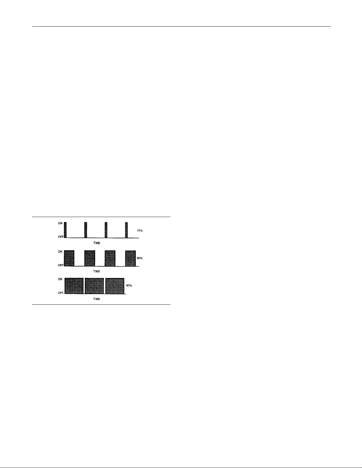
Duty Cycle – Refer to “Pulse Width Modulation”.
Electron
engine control is a complete electronic system.
The electronic engine control monitors the engine
operati
control also controls the engine operation under all
conditions.
Electronic Service Tool – The electronic service
tool allows a computer (PC) to communicate with the
ECM.
on under all conditions. The electronic engine
ence or presence of coolant at the
rature Sensor – The coolant
sed for communication with other
ne Speed – The desired engine speed
ition sensor, the engine speed/timing
c system malfunction.
check engine light. The diagnostic lamp
lated signal. Digital sensors are supplied
ensor Supply – The+8VDCsupplyfrom
rrent (DC) – Direct current is the type of
nector, or Deutsch DT – This is a type
ic Engine Control – The electronic
Page 10

10 RENR2696-01
Troubleshooting Section
Electronic Control Module (ECM) – The ECM
is the control c
provides power to the electronics. The ECM monitors
data that is input from the sensors of the engine. The
ECMactsasago
and the power of the engine.
Engine Monit
of the electronic engine control that monitors the
sensors. This also warns the operator of detected
problems.
Engine Oil Pressure Sensor – The engine oil
pressure sen
sensor sends the signal to the ECM.
Engine Speed
speed/timing sensor provides a variable amplitude
and pulse width modulated signal to the ECM. The
ECM interpr
and the engine speed.
Event Code
in order to indicate an abnormal engine operating
condition. These codes usually indicate a mechanical
problem in
Failure Mode Identifier (FMI) – This identifier
indicates
by the component. The FMI has been adopted from
the SAE practice of J1587 diagnostics.
Flash Programming – Flash programming is the
method of programming or updating an ECM with
an electr
of replacing components.
Fuel Rati
is based on the control of the ratio of the fuel to air.
The FRC is used for purposes of emission control.
When the
air pressure (more air into the cylinder), the FRC
increases the FRC Limit (more fuel into the cylinder).
Fuel Temperature Sensor – The fuel temperature
sensor detects the fuel temperature. The ECM
monitor
thecalculatedfuelrateaccordingly.
Full Loa
that represents the fuel system adjustment. This
adjustment is made at the factory in order to fine tune
the fue
is stamped on the engine information ratings plate.
This parameter must be programmed.
Full Torque Setting (FTS) – The FTS is similar
to the full load setting. This parameter must be
progr
s the fuel temperature and the ECM adjusts
l system. The correct value for this parameter
ammed.
omputer of the engine. The ECM
vernor in order to control the speed
oring – Engine Monitoring is the part
sor measures engine oil pressure. The
/Timing Sensor – The engine
ets this signal as the crankshaft position
– An event code may be activated
stead of an electrical system problem.
the type of failure that has been experienced
onic service tool over the data link instead
o Control (FRC) – The FRC is a limit that
ECM senses a higher intake manifold
d Setting (FLS) – The FLS is the number
Harness – The harness is the bundle of wiring
(loom) that con
system.
Hertz (Hz) – He
frequency in cycles per second.
Intake Manifo
intake manifold air temperature sensor detects the
air temperature in the intake manifold. The ECM
monitors the
intake manifold in order to adjust injection timing and
other performance functions.
Intake Manifold Pressure Sensor – The air
pressure in the intake manifold may be different to
the air press
pressure). This difference in air pressure can be
caused by variable air velocity within the manifold.
The differe
by an increase in air pressure by a turbocharger
(if equipped). The sensor for the intake manifold
air pressu
atmospheric pressure and the air pressure in the
intake manifold.
Integrated Electronic Controls – The engine is
designed with the electronic controls as a necessary
part of th
without the electronic controls.
J1939 CAN
diagnostic communications data link that is used to
communicate between the ECM and the electronic
service t
Logged Dia gnostic Codes – Logged diagnostic
codes ar
These codes are meant to be an indicator of possible
causes for intermittent problems. Refer to the
term “Di
information.
MAB – Thi
inside the “VPM30” Fuel Injection Pump. The MAB
is a signal wire from the ECM to the Fuel Injection
Pump.
Open Circuit – An open circuit is a condition that is
caused
or a connection that is broken. When this condition
exists, the signal or the supply voltage can no longer
reach
Parameter – A parameter is a value or a limit that
is pro
characteristics or behaviors of the engine.
agnostic Code” in this glossary for more
by an open switch, or by an electrical wire
the intended destination.
grammable. This helps determine specific
nects all components of the electronic
rtz is the measure of electrical
ld Air Temperature Sensor – The
air temperature and other data in the
ure outside the engine (atmospheric
nce in pressure can also be caused
re measures the difference between
esystem.Theenginewillnotoperate
Data Link – This data link is a SAE
ool.
e codes which are stored in the memory.
s is a Bosch acronym for the fuel shutoff
Page 11
RENR2696-01 11
Troubleshooting Section
Password – A password is a group of numeric
characters or a
group of alphanumeric characters
that is designed to restrict access to parameters. The
electronic system requires correct passwords in order
to change some
parameters (Factory Passwords).
Refer to Troubleshooting, “Factory Passwords” for
more information.
Personality Module – This module is inside the
ECM. The module contains all the instructions
(software) f
or the ECM and the module contains
the performance maps for a specific engine. The
personality module may be reprogrammed through
flash progr
amming.
Power Cycled – Power cycled happens when power
to the ECM is
cycled: ON, OFF, and ON. Power
cycled refers to the action of cycling the keyswitch
from any position to the OFF position, and to the
START/RUN p
osition.
Pulse Width Modulation (PWM) – The PWM is a
signal tha
t consists of pulses that are of variable
width. These pulses occur at fixed intervals. The ratio
of “TIME ON” versus total “TIME OFF” can be varied.
This ratio
is also referred to as a duty cycle.
Short Circuit – A short circuit is a condition that has
an electrical c
ircuit that is inadvertently connected to
an undesirable point. An example of a short circuit
is a wire which rubs against a vehicle frame and
this rubbing e
ventually wears off the wire insulation.
Electrical contact with the frame is made and a short
circuit results.
Signal – The signal is a voltage or a waveform that
is used in order to transmit information typically from
asensortoth
eECM.
Supply Voltage – The supply voltage is a constant
voltage that
is supplied to a component in order to
provide the electrical power that is required for the
component to operate. The power may be generated
by the ECM or
the power may be battery voltage that
is supplied by the engine wiring.
System Conf
iguration Parameters – System
configuration parameters are parameters that affect
emissions and/or operating characteristics of the
engine.
Throttle Position – Thethrottlepositionisthe
interpret
ation by the ECM of the signal from the
throttle position sensor or the throttle switch.
Illustration 3
g00284479
Rated Fuel Limit – This term indicates the maximum
allowable fuel position (longest injection pulse). This
position will produce rated power for this engine
configuration.
Reference Voltage – Reference voltage is a
regulated voltage and a steady voltage that is
supplied by the ECM to a sensor. The reference
voltage is used by the sensor to generate a signal
voltage.
Sensor – A sensor is a device that is used to detect
a change in pressure, temperature, or mechanical
movement. The information that is detected is
converted into an electrical signal.
Throttle P
osition Sensor – The throttle position
sensor is an electronic sensor that is connected to an
accelerator pedal or a hand lever. This sensor sends
aPWMsign
al to the ECM that is used to calculate
desired engine speed.
Throttle
Switch – The throttle switch sends a signal
to the ECM that is used to calculate desired engine
speed.
TopDeadCenter –Top dead center refers to the
crankshaft position when the engine piston position
is at the
highest point of travel. The engine must be
turned in the normal direction of rotation in order to
reach this point.
Tot al Tattletale – The total tattletale is the total
number of changes to all the parameters that are
stored i
ntheECM.
Voltage Load Protection Module (“VLPM”) – The
“VLPM” m
onitors the voltage of the electronic system.
The “VLPM”will eliminate any high voltage conditions
that occur. The “VLPM” will protect the fuel injection
pump fr
om any high voltage conditions that could
damage the pump.
Page 12

12 RENR2696-01
Troubleshooting Section
i01798102
Electronic Service Tools
Electronic Service Tools are designed to help the
service techni
electronic engines. Several tools are available to
assist the service technician.
Some of the included Diagnostic Functional Tests
in this manual require two short jumper wires. The
jumper wires a
some wiring harness circuits by shorting two adjacent
terminals together in a connector.
A long extension wire may also be needed to check
the continuity of some wiring harness circuits.
Electronic Service Tool
The electronic service tool can display the following
information:
Parameters
•
Event codes
•
Diagnostic codes
•
cian with the diagnosis and repair of
re used to check the continuity of
Table 1
Required Electronic Service Tools for the Use
Part
Number
N/A
N/A
of the Electronic Service Tool
Description
Required
IBM compatible PC with
266 MHz Pentium processor
64 MB of RAM
400 MB of available hard drive space
CD-ROM drive
3.5" 1.44 MB floppy disk drive
VGA monitor or display (800 x 600)
Microsoft® Windows 2000, XP, ME,
NT 4.0, 98, or 95
RS232 port with 16550AF UART
Recommended
IBM compatible PC with
450 MHz Pentium III processor
128 MB of RAM
1 GB of available hard drive space
40X speed CD-ROM drive or
8X speed DVD drive
3.5" 1.44 MB floppy disk drive
Super VGA monitor or display (800 x 600)
Microsoft® Windows 2000, XP, ME,
NT 4.0, or 98
RS232 port with 16550AF UART
Engine configuration
•
The electron
icservicetoolcanbeusedbythe
technician to perform the following functions:
Diagnostic
•
Sensor calibrations
•
Flash programming
•
Set paramet
•
tests
ers
The following components are required to use the
electronic
service tool to service the engine.
Page 13
RENR2696-01 13
Troubleshooting Section
Connecting the Electronic Service Tool
and the Communi
cation Adapter II
Support for the Electronic Service Tool
For authorization and ordering information, contact
Perkins Help Desk - Irlam.
If you are having problems with the software, you can
contact the Perkins Service Systems Support Center.
Optional Service Tools
The following
table contains service tools that may
be helpful to service the engine.
Table 2
Optional Service Tools
Part Number Description
N/A Suitable Digital Multimeter
N/A Suitable Breakout T (70 pin)
N/A Suitable Cri
N/A Suitable Cylinder Pressure Indicator
N/A Suitable Battery Load Tester
mp Tool
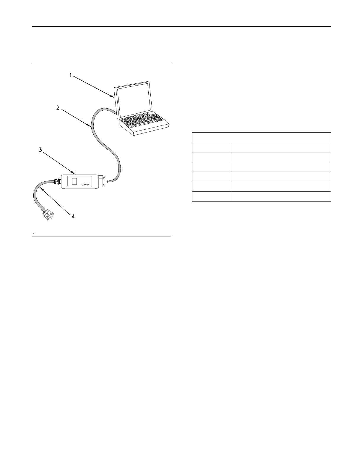
Illustration 4
(1) Personal computer (PC)
(2) Adapter Cable (Computer Se rial Port)
(3) Communication Adapter II
(4) Adapter Cable Assembly
g00647144
Note: Items (2), (3), and (4) are part of the
Communication Adapter II Gp.
Use the following procedure to connect the Electronic
Service Tool and the Communication Adapter II.
1. Turn the keyswitch to the OFF/RESET position. If
the keyswitch is not placed in the OFF/RESET
position, the engine may start.
2. Connect cable (2) between the “COMPUTER”
end of communication adapter (3) and the RS232
serial port of PC (1).
3. Connect cable (4) between the “DATA LINK” end
of communication adapter (3) and the service tool
connector.
4. Turn the keyswitch to the ON position. If the
electronic service tool and the communication
adapter do not communicate with the ECM, refer
to Troubleshooting, “Electronic Service Tool Will
Not Communicate With ECM”.
02270470
i
Diagnostic Codes
his list identifies the respective faults for the CID
T
FMI and the J Code FMI codes. The CID FMI codes
are displayed on a laptop computer. The J Code FMI
odes are displayed on a Diagnostic Code Reader.
c
The Diagnostic Code Reader is also known as the
Hand Held Tool.
The Component Identifier (CID) is a number that
identifies the specific component that caused a
diagnostic code to be logged.
The Failure Mode Identifier (FMI) is a number
that indicates the type of failure that has been
experienced by the component.
The J1939 Code is another system that identifies the
specific component that caused a diagnostic code to
be logged.
Note: Event codes are not supported by J1939
numbers. Event codes use (CID) and (FMI) numbers.
The following (FMI) numbers 0, 1, 15, 16, 17, and 18
are used for event codes.
Page 14

14 RENR2696-01
Troubleshooting Section
Table 3
CID FMI Code J Code FMI Code
0041 03 J0678 03
8V Sensor Powe
r Supply, voltage more than normal
0041 04 J0678 04 8V Sensor Power Supply, voltage less than normal
0091 02 J0091 02 Throttle Demand Sensor, erratic or intermittent
0091 03 J0091 03 Throttle Demand Sensor, open circuit or shorted high
0091 04 J0091 04
0091 08 J0091 08
0091 12 J0091-12
0100 03 J0100 03
0100 04 J0100 04
0100 10
0102 03 J0102 03
0102 04 J0102 04
0102 10
Throttle Demand Sensor, shorted low
Throttle Demand Sensor, abnormal signal
Throttle Demand Sensor, power supply failure
Engine Oil Pressure Sensor, open circuit or shorted high
Engine Oil Pressue Sensor, shorted low
Engine Oil Pressure Sensor, power supply open circuit
Intake Manifold Pressure Sensor, open circuit or shorted high
Intake Manifold Pressure Sensor, shorted low
Intake Ma
nifold Pressure Sensor, power supply open circuit
0105 03 J0105 03 Intake Manifold Temperature Sensor, open circuit or shorted high
0105 04 J0105 04 Intake Manifold Temperature Sensor, shorted low
0110 03 J0110 03 Engine Coolant Temperature Sensor, open circuit or shorted high
0110 04 J0110 04
Engine Coolant Temperature Sensor, shorted low
0168 02 J0168 02 Battery Voltage, intermittent or incorrect
0174 02 J0174 0
2
Fuel Temperature Sensor, erratic or intermittent
0247 09 J0639 09 J1939 Datalink, abnormal update
0253 02 J0234 02 Incorrect ECM Software
3
0262 0
0262 04 J0620 04
0266 02
0267 02
0320 02 J0637 02
0320 11 J0637 11
0321 02
0342 02 J0723 02
0590 02
0774 02
J0620
03
5V Sensor Power Supply, voltage more than normal
5V Sensor Power Supply, voltage less than normal
Crank without injection, switch state incorrect
External Stop Switch, data erratic or incorrect
Speed and Timing Sensor, intermittent loss of signal
Speed and Timing Sensor, loss of signal
Diagnostic Reset Switch, intermittent or incorrect
Speed and Timing Sensor No.2, intermittent signal
ECM identified missing timing pulse
rottle Demand Sensor No.2, erratic or intermittent
Th
0774 03 Throttle Demand Sensor No.2, open circuit or shorted high
0774 04 Throttle Demand Sensor No.2, shorted low
74 08
07
0774 12
1627 03
1639 09
1684 00 J1077 00
Throttle Demand Sensor No.2, abnormal signal
Throttle Demand Sensor No.2, power supply failure
Fuel Pump Relay, did not turn off
Machine Security System Module, abnormal update
Fuel Injection Pump, fuel temperature more than normal
Fault Description
(continued)
Page 15

RENR2696-01 15
Troubleshooting Section
(Table 3, contd
1684 02 J1077 02 Fuel Injection Pump, software failure
1684 03 J1077 03
1684 04 J1077 04
1684 05 J1077 05 Fuel Injection Pump, invalid pulse width
1684 07 J1077 07
1684 08 J1077 08
1684 09 J1077 09
1684 10 J1077 10
1684 11 J1077 11
1684 12 J1077 12
1684 14 J1077 14 Fuel Injection Pump, no communications
1690 08
1743 02
1894 02
1895 02
Event Cod
E015 110 16 High Engine Coolant Temperature Derate
E016 110 00 High Engine Coolant Temperature Sutdown
E017 110 15 High Engine Coolant Temperature Warning
E025 105 16 High Intake Air Temperature Derate
E027 105 15 High Intake Air Temperature Warning
E039 100 18
E040 100 01 Low Engine Oil Pressure Shutdown
E054 174 16 High Fuel Temperature Derate
E056 174 15 High Fuel Temperature Warning
E100 100 17
E190 190 15
E442
E883 Engine Failed To Stop When Fuel Solenoid Disengaged
)
Fuel Injection Pump, fuelling fault
Fuel Injection Pump, supply voltage fault
Fuel Injection Pump, mechanical fault
Fuel Injection Pump, crankshaft reference fault
Fuel Injection Pump, CAN fault
Fuel Injection Pump, fuel shutoff signal error
Fuel Injection Pump, internal sensor fault
Fuel Injection Pump, device failure
Analogue Speed Control, signal abnormal
Engine Mode Selection Switch State, invalid state
Set Speed Control Disengage Switch, invalid state
Set Speed Control Speed Toggle Switch, invalid state
e
CID FMI Co
de
Low Eng
Low Engine Oil Pressure Warning
Engine Overspeed Warning
Engi
ine Oil Pressure Derate
ne Failed To Stop With A No-Fuel Command
i01878735
Indicator Lamps
Some engine applications are equipped with Indicator
Lamps. Indicator lamps can be used as a diagnostic
aid. There are two lamps. One lamp has an orange
lens and the other lamp has a red lens.
These indicator lamps can be used in two ways:
The indicator lamps can be used to identify the
•
current operational status of the engine. The
indicator lamps can also be used to indicate that
the engine has a fault. This system is automatically
operated via the ignition switch.
The indicator lamps can be used to identify active
•
diagnostic codes. This system is activated by
pressing the Flash Code button.
Page 16

16 RENR2696-01
Troubleshooting Section
Use the lamps to
check the engine’s
operational status or the existence
of any engine faults.
Each lamp will
ways in order to identify the engine’s operational
status. The lamps will also be illuminated in a
combination
fault. These combinations of illuminated lamps have
the following meanings:
The status of the lamps before the engine is
cranked. This also acts as a lamp check.
When the ignition switch is turned ON, the lamps will
be illuminated for 2 seconds. The lamps are then
OFF unless t
Table 4
Orange
lamp
(status)
ON ON
Refer to the
comments.
The lamp status with the cold starting aid in
operation and before the engine is cranked.
be illuminated in a combination of
of ways to indicate if the engine has a
he cold starting aid is required.
Red lamp
(status)
The lamps will be illuminated
for 2 seconds or the lamps
will be illuminated until the
engine is cranked.
OFF ThelampwillbeOFFunless
thecoldstartingaidis
required.
Comments
Table 6
Orange
lamp
(status)
OFF OFF
ON ON
Red lamp
(status)
Comments
There are no apparent
problems.
The lubricating oil pressure
is low. This low oil pressure
was measured after the set
delay had expired.
The status of the lamps after cranking has failed
to start the engine.
Table 7
Orange
lamp
tatus)
(s
OFF OFF No faults were detected.
ON OFF An electrical fault was
OFF
Red lamp
(status)
detected.
Flashing The engine was activated
when a serious fault was
detected.
Comments
Other combinations of illuminated indicator lamp
The following combinations of lamp status may also
be exhibited when the engine is either running or
when the engine has been shut down automatically.
The orange lamp will be illuminated until the engine
is ready to be cranked.
Table 5
Orange
lamp
(status)
ON OFF The status of the lamps
Then OFF OFF This is the status of the
Red lamp
(status)
Comments
withthecoldstartingaidstill
operating.
lamps while the engine is
being cranked. The cold
starting aid is no longer
operating.
This is the status of the lamps while the engine
is being cranked.
Unless there is a fault, the engine monitoring system
will not illuminate the indicator lamps while the
engine is being cranked. For example if there is a
lack of lubricating oil pressure after the start delay is
exceeded. This type of fault will cause the stop lamp
for the engine to be illuminated.
Page 17
RENR2696-01 17
Troubleshooting Section
Table 8
Orange
lamp
(status)
OFF OFF No faults were detected.
OFF ON
Flashing
OFF
ON OFF An electrical fault has been
ON ON
ON
Flashing ON The oil pressure is low and
Red lamp
(status)
OFF
Flashing
Flashing
Comments
The oil pressure is low.
Either the coolant temperature
is high or the intake air
temperature is high. The
engine may be derated.
Either a fault has caused the
engine to be
shut down or the engine has
exceeded the condition for a
derate.
detected.
The oil pressure is low and
thereisanelectricalfault.
Either a fault has caused the
engine to
engine has exceeded the
conditions for a derate. There
is also a
either the coolant temperature
or the intake air temperature
is high. The engine may be
derated.
automatically
shut down or the
n electrical fault.
Usethelampstoidentifyactive
diagnostic codes.
Table 9
CID
number
0041
0091
0100
0102
0105
0110
0174 Fuel Temperature Sensor 165
0247 J1939 Data
0253 Personality Module 416
0262
0320
0342 Secondary Engine Speed
0774
1684 Fuel Injection Pump 158
1743
1894 Cruise Control Status Switch 427
1895 Toggle Switch for Cruise
8 Volt Power Supply
Throttle Position Sensor
Engine Oil Pressure Sensor
Intake Manifold Pressure
Sensor
Intake Manifold Air Temperature
Sensor
Engine Coolant Temperature
Sensor
5 Volt Power Supply
Engine Sp
Sensor
Secondary Throttle Position
Sensor
Mode Selector Switch for
Engine Operation
Control Speed
Description Flash
Link
eed/Timing Sensor
code
517
154
157
135
133
168
514
516
141
142
155
144
428
The indicator lamps can be used to identify an active
code by flashing in a sequence that will identify the
active code. The active code that is flashed by the
indicator lamps is only the component identifier (CID).
The indicator lamps cannot identify the fault with the
component. The active code that is flashed by the
indicator lamps is not a Failure Mode Identifier (FMI).
When the Flash Code feature is activated the
indicator lamps will flash the codes of all active
codes. Activation of the indicator lamps is achieved
by cycling the keyswitch OFF and ON twice within
3 seconds.
There will be a delay of 2 seconds before the lamps
start to flash the identity of any active code.
An active CID with two digits will be flashed in
the following sequence. There will be a number of
flashes. The number of flashes will equal the first
digit. There will be a delay before a second number
of flashes. The second number of flashes will equal
the second digit. For example, a CID code of 41 will
be four flashes, a delay and the one flash. A three
digit CID code will have two delays between the
sequence of flashes. A four digit CID code will have
three delays between the sequence of flashes.
Each flash of the lamp will be 0.5 seconds long.
There will be a delay between each flash of 0.3
seconds.
Page 18

18 RENR2696-01
Troubleshooting Section
Each delay between each digit of the code will be
2 seconds.
After one active code has been identified there will
be a delay of 5 s
is flashed.
The sequence o
restarted at any time by reactivating the cycling of
the keyswitch.
econds before the next active code
f flashing the active codes may be
i01798103
Replacing the ECM
NOTICE
Keep all parts clean from contaminants.
Contaminants may cause rapid wear and shortened
component life.
The engine is
Module (ECM). The ECM contains no moving parts.
Follow the troubleshooting procedures in this manual
in order to b
the problem. Verify that the suspect ECM is the
cause of the problem.
Note: Ensure that the ECM is receiving power
and that the ECM is properly grounded before
replacemen
Troubleshooting, “Electrical Power Supply Circuit Tes t ”.
AtestECMcanbeusedinordertodetermineif
the ECM on the engine is faulty. Install a test ECM
in place of
module into the test ECM. Program the parameters
for the test ECM. The parameters must match
the param
following test steps for details. If the test ECM
resolves the problem, reconnect the suspect ECM.
Verify th
replace the ECM.
equipped with an Electronic Control
e sure that replacing the ECM will correct
t of the ECM is attempted. Refer to
the suspect ECM. Flash the personality
eters in the suspect ECM. Refer to the
at the problem returns. If the problem returns,
Note: When a new ECM is not available, you may
need to remove a
service. The ECM must have the same serial number
suffix. Ensure that the replacement ECM and the
Personality M
ECM. Be sure to record the parameters from the
replacement ECM. Use the “Copy Configuration ECM
Replacement
If the Personality Module and engine application are
not matched, engine damage may result.
Perform the following procedure in order to replace
the ECM.
1. Connect the electronic service tool to the service
tool connector.
2. Use the “Copy Configuration ECM Replacement”
function from the electronic service tool. If the
“Copy Configuration” is successful, proceed to
Step 4. If the “Copy Configuration” failed, proceed
to Step 3.
Note: You may want to record any Logged Faults
and Events for your records.
3. Record the parameters. Record all of the
parameters on the “Main Configuration” screen.
Also, record all of the parameters on the
“Throttle Configuration” screen and on the “Mode
Configuration” screen.
Note: If the parameters cannot be read, the
parameters must be obtained elsewhere. Some
parameters are stamped on the engine information
plate, but most parameters must be obtained from
the factory.
4. Remove the ECM.
a. Turn the keyswitch to the OFF position.
b. Turn the battery disconnect switch to the OFF
position.
n ECM from an engine that is not in
odule Interlock Code match the suspect
” function in the electronic service tool.
NOTICE
Use the e
in the suspect ECM. Record the parameters in the
suspect ECM. The personality module can be flashed
into th e
engine, the parameters must be programmed into
the new ECM.
lectronic service tool to read the parameters
new ECM. After the ECM is installed on the
c. Slacken the 4 mm Allen head screw and
disconnect the ECM 70-pin (P1/J1) connectors.
d. Remove the mounting bolts from the ECM.
e. Disconnect the grounding strap from the ECM.
5. Install the replacement ECM.
a. Usetheoldmountinghardwaretoinstallthe
replacement ECM. The mounting hardware
should be free of damage.
Page 19

RENR2696-01 19
Troubleshooting Section
b. Check that the ECM mounting hardware is
installed corr
used to protect the ECM from excessive
vibration. The ECM should be able to drift in
the rubber gro
c. Install the ground strap for the ECM on the
engine.
d. Reconnect the J1/P1 70 Pin connector to the
ECM. Tighten
connectors to a torque of 6 N·m (55 lb in).
6. Download the
a. Connect the electronic service tool to the
service conn
b. Select “WinFlash” from the “Utilities” menu of
the electron
c. Select the appropriate file.
7. If it is necessary, use the electronic service tool
to clear the rating interlock in the Personality
Module. To c
factory password when the electronic service tool
is first connected. Activating the “Test ECM” mode
will also cl
8. Use the electronic service tool to program the
parameter
a. If the “Copy Configuration” procedure was
successfu
Replacement” function to load the configuration
file into the ECM.
ectly. The rubber grommets are
mmets.
the Allen head screw on the
Flash file.
ector.
ic service tool.
lear the rating interlock, enter the
ear the rating interlock.
s. Perform the following procedure.
l, use the “Copy Configuration, ECM
Diagnostic Code – When a problem with the
electronic sys
diagnostic code. This indicates the specific problem
with the circuitry.
Diagnostic codes can have two different states:
Active
•
Logged
•
Active Code – An active diagnostic code indicates
that an active problem has been detected. Active
codes requir
active codes prior to servicing logged codes.
Logged Code –
the permanent memory of the ECM. The codes are
logged.
Event Code – An event code is generated by the
detection of an abnormal engine operating condition.
For example
oil pressure is too low. In this case, the event code
indicates the symptom of a problem.
Logged codes may not indicate that a repair is
needed. The problem may have been temporary. The
problem may
of the code. If the system is powered, it is possible
to generate an active diagnostic code whenever a
component
reconnected, the code is no longer active. Logged
codes may be useful to help troubleshoot intermittent
problems.
the performance of the engine and the electronic
system.
tem is detected, the ECM generates a
e immediate attention. Always service
Every generated code is stored in
, an event code will be generated if the
have been resolved since the logging
is disconnected. When the component is
Logged codes can also be used to review
b. If the “Copy Configuration” procedure failed,
configure the parameters individually. The
paramete
step 2.
9. Check for
passwords are required to clear Logged Events.
rs should match the parameters from
logged diagnostic codes. Factory
i01798104
Self-Diagnostics
The Electronic Control Module (ECM) has the ability
to detect problems with the electronic system and
with engine operation. When a problem is detected, a
code is generated. An alarm may also be generated.
There are two types of codes:
Diagnostic
•
Event
•
Page 20
20 RENR2696-01
Troubleshooting Section
i01798105
Sensors and Electrical
Connectors
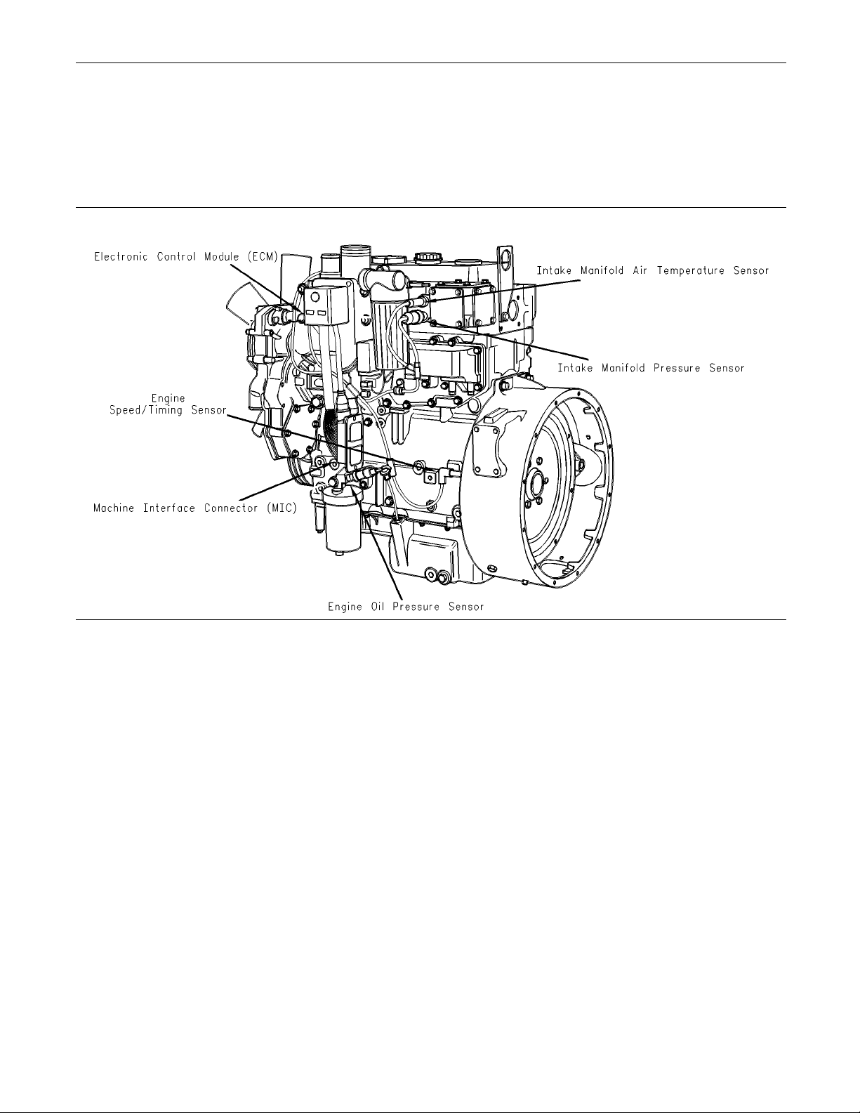
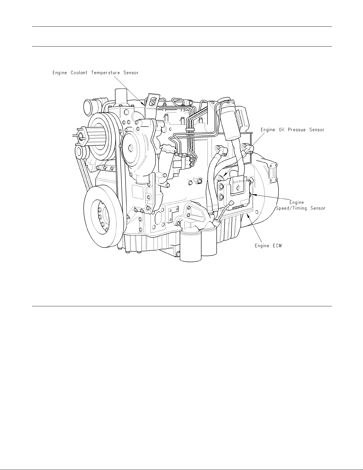
Illustration 5
1104
Typical example of left side sensor locations
g00954205
Page 21
RENR2696-01 21
Troubleshooting Section
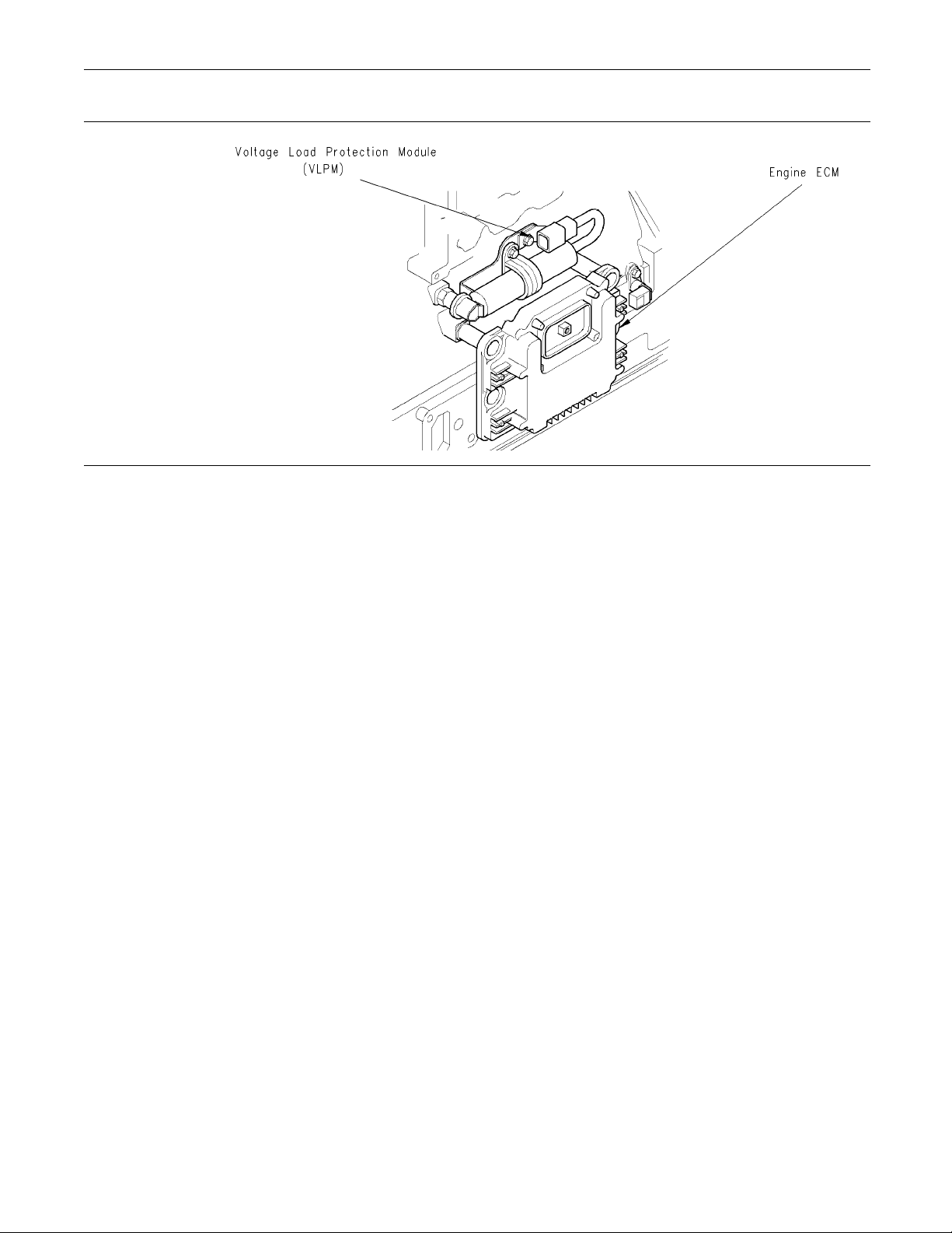
ion 6
Illustrat
1104 engine
Typical location of the VLPM
g00915379
tration 7
Illus
1104
Typical example of right side sensor locations
g00882117
Page 22
22 RENR2696-01
Troubleshooting Section
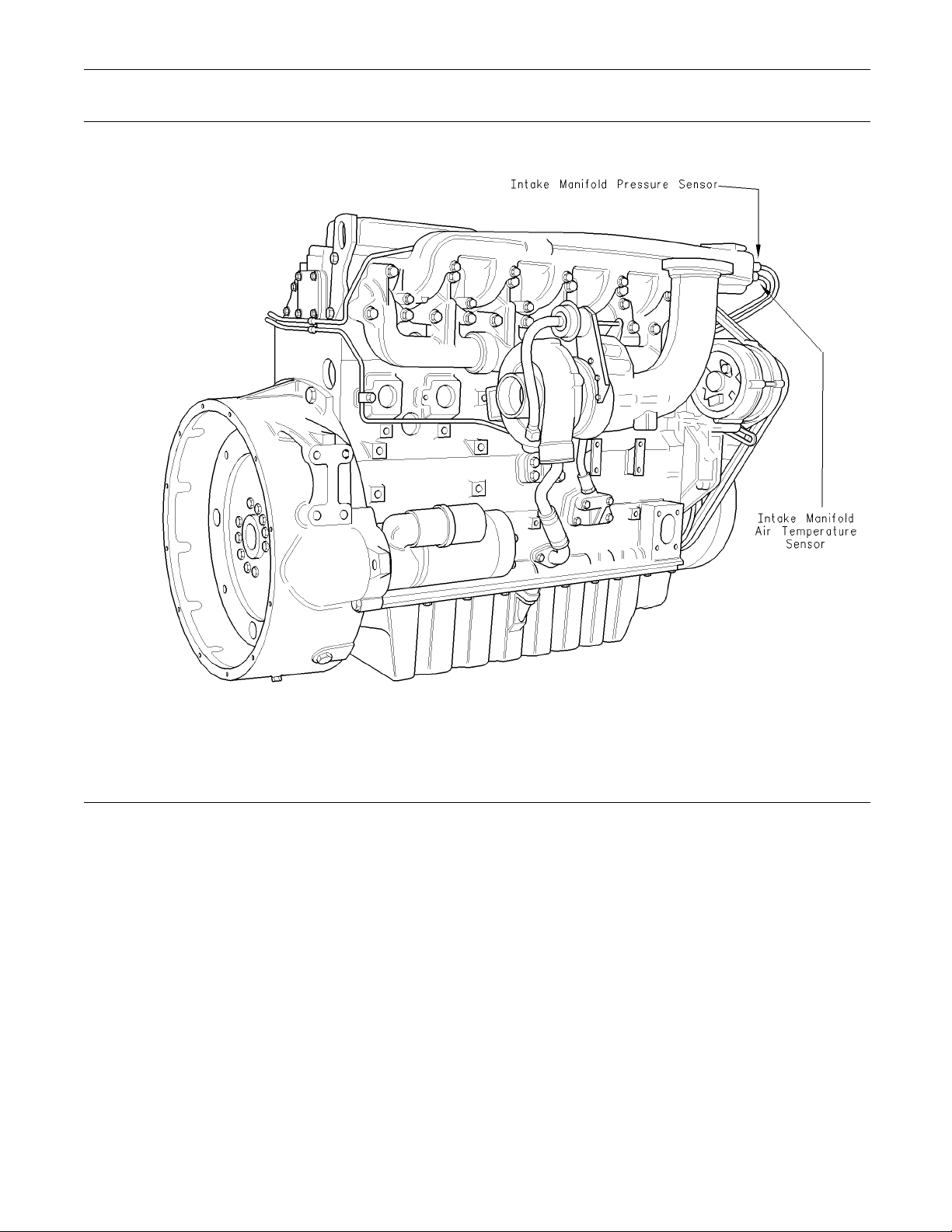
Illustration 8
1106
Typical example of left side sensor locations
g00884570
Page 23
RENR2696-01 23
Troubleshooting Section
Illustration 9
1106 engine
Typical location of the VLPM
g00908929
Page 24
24 RENR2696-01
Troubleshooting Section
Illustration 10
Typical example of right side sensor locations
1106
g00954214
Page 25
RENR2696-01 25
Troubleshooting Section
Table 10
Connector
J1/P1 ECM Connector
Harness
J20/P20 Machine Interface Connector
(70-Pin Engine Harness)
J40/P40 Fuel Injection Pump (3-Pin
Connector)
J100/P100 Engine Coolant Temperature
Sensor (2-Pin Connector)
J103/P103 Intake Mani
Sensor (2-Pin Connector)
J200/P200 Intake Manifold Pressure Sensor
(3-Pin Connector)
J201/P201 Engine Oil Pressure Sensor
(3-Pin Connector)
J401/P401 Speed/Timing Sensor (2-Pin
Connector)
Function
70 Pin Machine
fold Air Temperature
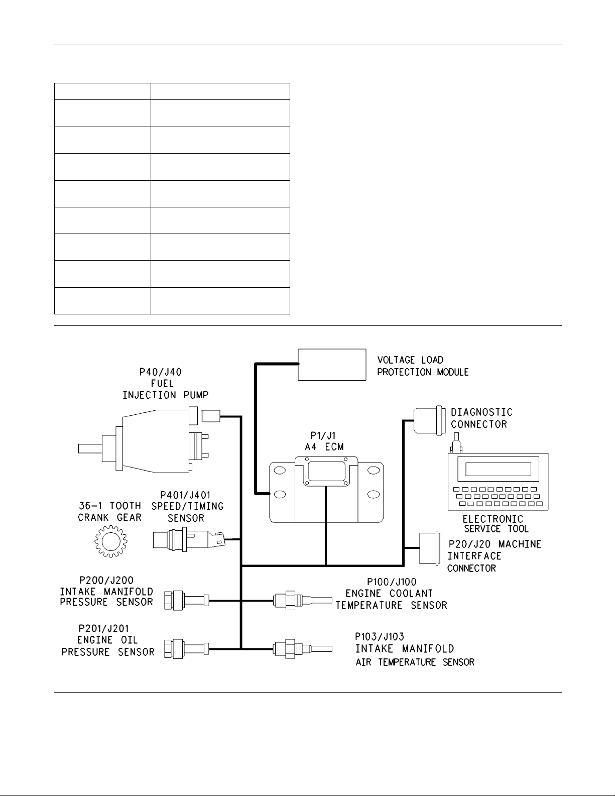
Illustration 11
Basic engine schematic
g00
954204
Page 26
26 RENR2696-01
Troubleshooting Section
i02294251
Engine Wiring Information
The wiring diagrams are revised periodically. The
wiring diagram
harness. For the most current information, always
check the revision number of the diagram. Use the
diagram with t
s will change with updates to the wiring
he latest revision number.
Illustration 12
Schematic for the fuel injection pump and ECM power supply for engines with a Machine Interface Connector that has 70 pins
Note: Each terminal end of the J1939 CAN data
link must be connected with a 120 ohm terminating
resistor.
Note: Some engines with a Machine Interface
Connector that has 70 pins do not have the following
wiring connections: 35, 50, 53, 54, 60, 62, 63, 64,
and 67.
Note: Digital outputs 7,8,9,10,11,12,13, and 14 are
only suitable for a 12 V system.
Machine Interface Connector
Two types of Machine Interface Connector are
available. One type of connector has 70 pins and
the other type has 31 pins. Illustration 13 and
illustration 14 show the layout for the Machine
Interface Connector with 70 pins. Illustration 15
and illustration 16 show the layout for the Machine
Interface Connector with 31 pins.
g01152042
Page 27
RENR2696-01 27
Troubleshooting Section
Illustration 13
g00955504
Page 28
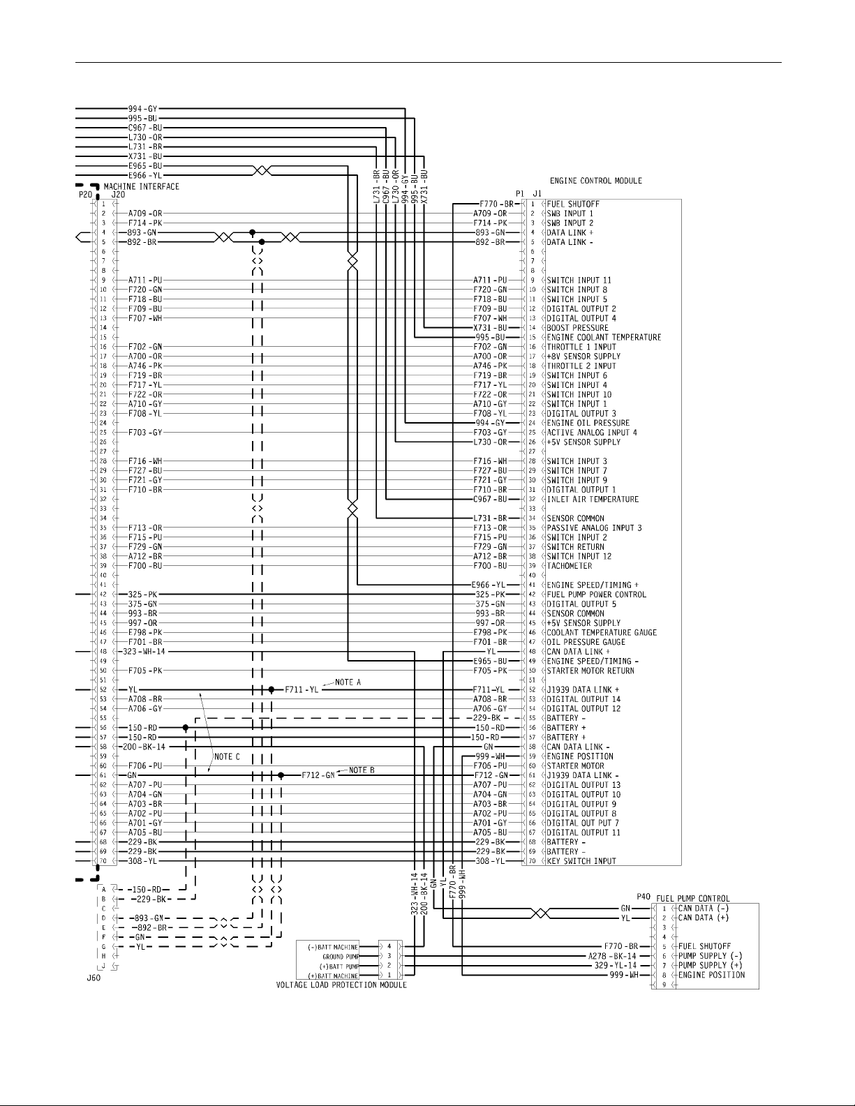
28 RENR2696-01
Troubleshooting Section
Illustration 14
g00955499
Page 29

RENR2696-01 29
Troubleshooting Section
Illustration 15
1152386
g0
Page 30
30 RENR2696-01
Troubleshooting Section
Illustration 16
g01152104
Page 31

RENR2696-01 31
Troubleshooting Section
The procedures in this manual refer to the connector
that has 70 pins
. Table 11 shows the conversion from
engine models that have a connector with 70 pins to
engine models that have a connector with 31 pins.
Table 11
Machine Interface Connector Pin Numbers
70 Pin 31 Pin
2 13
3 14
4 15
5
11 24
12 10
13 11
16* 27*
18 18
19 22
20 25
22 23
23 12
25 19
28 21
29 29
30 26
31 6
36 9
37 28
42 3
43
44 17
45 20
48 8
52 30
56 1
58 4
61 31
68 2
69* 1*
70 5
* These connections are not used on some
ine models.
eng
16
7
HarnessWireIdentification
Perkins identifies all wires with eleven solid colors.
The circuit number is stamped on the wire at a 25 mm
(1 inch) spacing. Table 12 lists the wire colors and
the color codes.
Table 12
Color Codes for the Harness Wire
Color Code Color Color Code Color
BK Black GN Green
BR Brown BU Blue
RD Red PU Purple
OR Orange GY Gray
YL Yellow WH White
PK Pink
For example, a wire identification of F702-GN on the
schematic would signify a green wire with the circuit
number F702. F702-GN identifies the power supply
for the 8 V throttle sensor.
Note: Always replace a harness wire with the same
gauge of wire and with the same color code.
Page 32

32 RENR2696-01
Troubleshooting Section
Programming Pa
rameters
i01798107
Programming Parameters
Theelectronicservicetoolcanbeusedtoview
certain parameters that can affect the operation of the
engine. The electronic service tool can also be used
to change certain parameters. The parameters are
stored in the Electronic Control Module (ECM). Some
of the parameters are protected from unauthorized
changes by passwords. Parameters that can be
changed have a tattletale number. The tattletale
number shows if a parameter has been changed.
i01798108
Factory Passwords
Passwords
Passwords a
to prevent unauthorized reprogramming of certain
parameters. Passwords prevent unauthorized
erasing of
factory to control access to engine calibration
parameters. Passwords allow the customer to control
access to c
Factory P
Factory passwords are required to clear any event
code. Fac
certain parameters such as Full Load Setting. The
factory passwords restrict changes to authorized
personne
been entered, the changes can then be made.
re part of a security system that helps
logged events. Passwords allow the
ertain programmable engine parameters.
asswords
tory passwords are required to change
l. When the correct factory passwords have
Note: The old interlock code is required to change
the interlock c
code is also required to change the interlock code
onausedECM.
The electronic service tool screen for factory
passwords will display the following parameters:
Serial number of the Electronic Control Module
•
(ECM)
Engine serial number
•
Serial numbe
•
Reason Code
•
Total Tattletale number
•
Note: The fa ct
for one programming session. A different set of
factory passwords will be required after you exit
the electron
passwords will be required to change information on
another electronic service tool screen.
ode on a used ECM. A new interlock
r for the electronic service tool
ory passwords may only be used
ic service tool screen. A different set of
Customer Passwords
Customer Passwords allow the customer to restrict
access to parameters that are programmable by the
customer. T
than eight characters. The customer has the option
of entering one or two customer passwords.
Note: If the owner loses the owner’s customer
passwords, the owner will not be able to program
parameter
passwords. By using factory passwords, one can
read customer passwords. Then use those customer
password
protected by customer passwords.
he customer passwords cannot be longer
s that are protected by customer
s to program parameters that have been
i01798110
In order
certain information must be given to an authorized
Perkins distributor. Since the factory passwords
contain
tool can be used to perform this function. In order
to obtain the factory passwords, proceed as if
you alr
point, if the factory passwords are actually needed,
the electronic service tool will request the factory
passwo
the information that is required to obtain the factory
passwords.
to obtain the proper factory passwords,
alphabetic characters, the electronic service
eady have the factory passwords. At some
rds and the electronic service tool will display
Flash Programming
Flash Programming – This is a method of
programming or updating the personality module in
an ECM.
Theelectronicservicetoolcanbeutilizedtoflash
a new personality module into the ECM. The flash
is accomplished by transferring the data from a PC
to the ECM.
Page 33

RENR2696-01 33
Troubleshooting Section
Flash Programm
ing a Personality
Module
1. Connect the electronic service tool to the service
tool connector.
2. Select “WinFlash” from the “Utilities” menu on the
electronic service tool.
“WinFlash” will try to detect an ECM.
3. When an ECM has
Selector” window will appear. Select the
appropriate ECM that needs to be flashed and
press “Brows
The “Flash File Selection” window will appear.
4. Theflashfilesarelocatedonadiskdriveandin
a directory. Select the correct disk drive and the
correct dire
the electronic service tool.
Alistoffla
5. Select the correct file from the list of flash files.
Read the “Fi
to verify that the correct file is selected. Select
“OK”.
ctory from “Drives” and “Directories” on
sh files will appear.
le Info” and the “Description” in order
been detected, the “ECM
e”.
6. Select the “Begin Flash” button in order to program
the personality module.
When the flash is completed, this message will
appear: “Flash Completed Successfully”.
7. Start the engine and check for proper operation.
a. If a diagno
ECM Software is generated, program any
parameters that were not in the old personality
module.
b. Access the “Configuration” screen under
the “Servi
the parameters that require programming.
Look under the “Tattletale” column. All of the
paramete
more. If a parameter has a tattletale of 0,
program that parameter.
stic code of 253-02 Incorrect
ce”menuinordertodetermine
rs should have a tattletale of 1 or
“WinFlash” Error Messages
If you rec
programming, click on the “Cancel” button in order
to stop the process. Access the information about
the “ECM
Make sure that you are flashing the correct file for
your engine.
eive any error messages during flash
Summary” under the “Information” menu.
Page 34

34 RENR2696-01
Troubleshooting Section
System Configuration
Parameters
i01798111
System Configuration
Parameters
System Configuration Parameters affect the
emissions of the engine or the power of the engine.
System configuration parameters are programmed
at the factory. Normally, system configuration
parameters would never need to be changed
through the life of the engine. System configuration
parameters must be reprogrammed if an ECM is
replaced. Unless the engine rating has changed,
system configuration parameters do not need to
be reprogrammed when the Personality Module is
replaced. The correct values for these parameters
are stamped on the engine information ratings plate.
The engine information ratings plate is located on
the valve cover or on the air intake manifold. Factory
passwords are required to change these parameters.
The following information is a description of the
system configuration parameters.
When an ECM is replaced this rating interlock code
must match the c
rating interlock code does not match the code that is
stored in the ECM, both of the following situations
will exist:
The engine will not run.
•
The diagnostic code 253-02 (Incorrect ECM
•
Software) will be active.
Note: The flash programming of a new rating
interlock replaces the old rating interlock.
This code does not need to be programmed when
the replacement ECM is from the same engine rating.
If the ECM is from a different engine rating, then
the following components may need to be changed:
pistons, fue
The engine information ratings plate must also be
changed in order to reflect the new rating.
Some vehicle systems such as the cooling system
or the transmission may also require changes when
the engine i
dealer for further information.
odethatisstoredintheECM.Ifthe
l injectors, and other components.
s rerated. Please contact the local OEM
“Engine Serial Number”
“Full Load Setting”
“Full Load Setting” is a number that represents
the adjustment to the fuel system that was made
atthefactoryinordertofinetunethefuelsystem.
The correct value for this parameter is stamped
on the engine information ratings plate. If the
ECM is replaced, the “full load setting” must
be reprogrammed in order to prevent a 253-02
diagnostic code from becoming active.
“Full Torque Setting”
“Full Torque Setting” is similar to “Full Load Setting”.
If the ECM is replaced, the full torque setting must
be reprogrammed in order to prevent a 253-02
diagnostic code from becoming active.
Rating Interlock
The Rating Interlock is a code that prevents the use
of an incorrect power rating and/or emission rating
for a specific engine. Each horsepower rating and
each emission certification has a different code to all
other horsepower ratings and emission certifications.
WhenanewEC
number in the ECM is not programmed. The “Engine
Serial Number” should be programmed to match the
engine ser
information plate.
M is delivered, the engine serial
ial number that is stamped on the engine
“ECM Software Release Date”
This para
and this parameter is not programmable. The “ECM
SoftwareReleaseDate”isusedtoprovidethe
version o
and the software change levels can be monitored by
this date. The date is provided in the month and the
year (NOV
is the year (1999).
meter is defined by the rating interlock
f the software. The Customer parameters
99). NOV is the month (November). 99
Page 35

RENR2696-01 35
Troubleshooting Section
Troubleshooti
ng without a
Diagnostic Code
i01798099
Alternator Noise
(Noisy Operation)
Note: This is NOT an electronic system problem.
Refer to Testing and Adjusting for information on
determining the cause of this condition.
Probable Causes
Alternator drive belts
•
Alternator drive pulley
•
Alternator bearings
•
Recommended Actions
Alternator Drive Belts
Alternator Will Not Charge
(Charging Problem)
Note: This is N
Probable Caus
Alternator drive belts
•
Charging circuit
•
Regulator
•
Alternator
•
Recommended Actions
Alternator Drive Belts
1. Inspect the co
If the alternator drive belts are worn or damaged,
replace the belts. Refer to Disassembly and
Assembly, “A
and Assembly, “Alternator - Install”.
OT an electronic system problem.
es
ndition of the alternator drive belts.
lternator - Remove” and Disassembly
i01798098
1. Inspect the condition of the alternator drive belts.
If the alternator drive belts are worn or damaged,
replace the belts. Refer to Disassembly and
Assembly, “Alternator - Remove” and Disassembly
and Assembly, “Alternator - Install”. Ensure that
the alternator drive belts are in alignment. Inspect
the alternator mounting bracket for cracks and
wear. Repair the mounting bracket or replace
the mounting bracket in order to ensure that the
alternator drive belts and the alternator drive
pulley are in alignment.
2. Check the tension on the alternator drive belts.
Adjust the tension, if necessary. Refer to Testing
and Adjusting, “V-Belt - Test”.
Alternator Drive Pulley
Loosen the nut for the alternator drive pulley and
tighten the nut to the correct torque. Refer to
Specifications, “Alternator and Regulator” for the
correct torque.
Alternator Bearings
Verify that there is excessive play of the shaft in
the alternator and that the alternator bearings are
worn. The alternator is a nonserviceable item. The
alternator must be replaced if the bearings are worn.
Refer to Disassembly and Assembly, “Alternator
- Remove” and Disassembly and Assembly ,
“Alternator - Install”.
Check the ten
Adjust the belt tension if the tension is incorrect.
Refer to Testing and Adjusting, “V-Belt - Test”.
sion on the alternator drive belts.
Charging Circuit
Inspect the b
the charging circuit. Clean all connections and tighten
all connections. Replace any faulty parts.
attery cables, wiring, and connections in
Alternator or Regulator
Verify that
correctly. Refer to Testing and Adjusting, “Alternator
- Test”. The alternator is not a serviceable item. The
alternator
operating correctly.
the alternator or the regulator is operating
must be replaced if the alternator is not
i01798112
Battery
Note: This is NOT an electronic system problem.
Probable Causes
Faulty battery
•
Auxiliary device drains the battery current.
•
Page 36

36 RENR2696-01
Troubleshooting Section
Recommended Ac
tions
Faulty Battery
1. Verify that the battery is no longer able to hold a
charge. Refer to Testing and Adjusting, “Battery
-Test”.
2. Replace the battery. Refer to Operation and
Maintenance,
“Battery - Replace”.
Auxiliary Device
1. Verify that the auxiliary device drained the battery
by being left in the ON position.
2. Charge the battery.
3. Verify that th
ebatteryisabletomaintainacharge.
i01798113
Can Not Reach Top Engine
RPM
Recommended Ac
tions
Diagnostic Codes
Check for active diagnostic codes on the electronic
service tool. Troubleshoot any active codes before
continuing wi
th this procedure.
Fuel Supply
1. Check the fuel pressure. Refer to Systems
Operation, Testing and Adjusting, “Fuel System
Pressure - Tes
2. Ensure that the fuel system has been primed.
Refer to Syst
Adjusting, “Fuel System - Prime”.
3. Check the die
Systems Operation, Testing and Adjusting, “Fuel
Quality - Test”.
4. Check for air in the fuel system. Refer to Systems
Operation, Testing and Adjusting, “Air in Fuel Te s t ” .
t”.
ems Operation, Testing and
sel fuel for contamination. Refer to
Note: If this problem occurs only under load, refer to
Troubleshooting, “Low Power/Poor or No Response
to Throttle”.
Probable Causes
Refer to the logged codes.
•
Fuel supply
•
Air intake and exhaust system
•
Individual malfunctioning cylinders
•
Valve l as h
•
Low compression (cylinder pressure)
•
Fuel injection nozzles
•
Turbocharger (if equipped)
•
ECM parameters
•
Throttle signal from the throttle position sensor
•
5. Check that the fuel lines are tight and secured
properly.
6. Check for fuel supply lines that are restricted.
7. Check the fuel filters.
8. Visually ch
gauge may be faulty.
9. If the engin
water in the fuel.
10. Ensure tha
OPEN position.
11. If the temp
for solidified fuel (wax).
12. If the repa
proceed to “Air Intake and Exhaust System”.
Air Intake
1. Check the air filter restriction indicator, if equipped.
2. Ensure that the air filter is clean and serviceable.
eck the fuel tank for fuel. The fuel
e has a water separator, check for
t the fuel supply valve is in the full
erature is below 0 °C (32 °F), check
irs do not eliminate the problem
and Exhaust System
3. Check the a
the following defects:
Blockages
•
Restrictions
•
ir intake and the exhaust system for
Page 37

RENR2696-01 37
Troubleshooting Section
Damage to the air intake and exhaust lines and
•
hoses
4. Make all necessary repairs to the engine.
5. Ensure that the repairs have eliminated the
diagnostic code.
6. If the problem has not been eliminated, proceed
to “Individual Malfunctioning Cylinders”.
Individual Malfunctioning Cylinders
1. With the engin
high pressure fuel line to the fuel injection nozzle
of number 1 cylinder. Note if there is any reduction
in engine spe
line to the fuel injection nozzle.
2. Individuall
injection nozzle. If there is no reduction in the
engine speed refer to “Check the Turbocharger
(if equippe
3. If all cylinders have been checked and no
problems we
e speed at a fast idle, loosen the
ed. Tighten the high pressure fuel
y repeat this procedure for each fuel
d)”.
re detected proceed to “Valve Lash”.
Damaged cylinder head
•
Checking the Fuel Injection Nozzles
1. Remove the fuel
head. Refer to Disassembly and Assembly, “Fuel
Injection Nozzle - Remove”.
2. Check the fuel injection nozzles. Refer to Testing
and Adjusting, “Fuel Injection Nozzle - Test”.
3. Ensure that the repairs have eliminated the
problems.
4. If the problem has not been eliminated, proceed
to “Check the Turbocharger (if equipped)”.
injection nozzles from the cylinder
Check the Tu rbocharger (if equipped)
Note: The tur
Series engines are nonserviceable items. If any
mechanical fault exists then the turbocharger must
be replaced
1. Ensure that the mounting bolts for the turbocharger
are tight.
bochargers that are equipped on 1100
.
Valve Lash
1. Check the valve lash and reset the valve lash, if
necessary. Refer to Systems Operation, Testing
and Adjusti
Adjust”.
2. If the repai
“Check for Low Compression”.
Check for L
1. Remove the fuel injection nozzles and perform a
compressi
Testing and Adjusting, “Compression - Test ”data.
2. Make all ne
3. Ensure that the repairs have eliminated the faults.
4. If the repair does not eliminate the fault refer to
“Checking the Fuel Injection Nozzles”.
Examples of low compression are shown in the
following list:
Mechanical problem
•
Faulty pi
•
ng, “Engine Valve Lash - Inspect and
r does not eliminate the fault proceed to
ow Compression
on test. Refer to Systems Operation,
cessary repairs to the engine.
ston rings
2. Check that the turbocharger drain is not blocked
or restrict
3. Check that the turbocharger housing is free of dirt
and debris.
4. Check the turbocharger for worn bearings. Refer
to Systems O
“Turbocharger - Inspect”.
5. Check that
turbocharger. Refer to Systems Operation, Testing
and Adjusting, “Turbocharger - Inspect”.
6. Ensure that the wastegate on the turbocharger is
adjusted correctly. Refer to Systems Operation,
Te s t i ng a n
7. Make all necessary repairs to the engine.
8. Ensure that the repairs have eliminated the faults.
9. If the faul
“ECM Pa rameters”.
ECM Param
1. Ensure that the problem is not a programmed
paramete
ed.
peration, Testing and Adjusting,
the turbine blades rotate freely on the
d Adjusting, “Turbocharger - Inspect”.
t has not been eliminated proceed to
eters
r.
Worn cylinder bores
•
Worn valves
•
Faulty cy
•
linder head gasket
2. Ensure that the correct mode was selected by
using the
3. Use the electronic service tool to verify the correct
engine ra
electronic service tool.
ting for the engine.
Page 38

38 RENR2696-01
Troubleshooting Section
4. Use the electronic service tool to verify the
maximum engine
5. Use the electronic service tool to reset the
parameters to
6. Ensure that the repairs have eliminated the
performance p
7. If the repairs have not eliminated the faults
proceed to “Ch
Position Sensor ”.
Check the Sig
speed limit.
the OEM specifications.
roblems.
eck the Signal for the Throttle
nal for the Throttle Position
Sensor
1. Use the elect
signal for the throttle position sensor.
2. If the signal
“Throttle Position Sensor Circuit - Test”.
3. If the engin
Troubleshooting, “Throttle Switch Circuit - Test”.
ronic service tool and observe the
is erratic, refer to Troubleshooting,
ehasathrottleswitchreferto
Coolant in Engine Oil
i01798114
3. Remove the oil filter element or elements. Fit a
new engine oil f
crankcase with clean engine oil to the correct
level. Refer to the Operation and Maintenance
Manual, “Engi
information.
Cylinder Hea
1. Remove the cylinder head. Refer to Disassembly
and Assembly
correct procedure.
2. Inspect the c
signs of leakage.
3. Check the cyl
Testing and Adjusting, “Basic Block” for more
information. Correct the cylinder liner projection if
it is incorr
4. If all of the cylinder liner projections were correct,
and if there
gasket proceed to the recommended actions for
the Cylinder Head.
5. If any of the cylinder liner projections were
incorrect, and this had resulted in the failure of the
head gaske
ilter element or elements. Fill the
ne Oil and Filter - Change” for more
d Gasket
, “Cylinder Head - Remove” for the
ylinder head gasket for faults and any
inder liner projection. Refer to
ect.
was no obvious signs of a faulty head
t, fit a new head gasket.
Note: This is NOT an electronic system problem.
Refer to Testing and Adjusting for information on
determining the cause of this condition.
Probable Causes
Engine oil cooler core
•
Cylinder head gasket
•
Cylinder head
•
Cylinder block
•
Recommended Actions
Engine Oil Cooler Core
1. Drain the engine lubricating oil from the engine.
2. Check for leaks in the oil cooler core. Refer to
Testing and Adjusting, “Cooling System” for the
correct procedure. If a leak is found, install a
new oil cooler core. Refer to Disassembly and
Assembly, “Engine Oil Cooler - Remove” for the
correct procedure. Fit new seals between the oil
cooler and the oil cooler cover.
6. To fit a new cylinder head gasket, refer to
Disassemb
Install” for the correct procedure.
Cylinder H
Check the cylinder head for flatness. Refer to
Systems O
correct procedure.
Check for
found, repair the cylinder head and/or replace the
cylinder head. Refer to Disassembly and Assembly,
“Cylinde
If the cylinder head is flat and if the cylinder head is
not crack
for the Cylinder Block.
Cylinde
Inspect the cylinder block for cracks. If a crack is
found, r
block.
ly and Assembly, “Cylinder Head -
ead
peration, “Cylinder Head - Inspect” for the
cracks in the cylinder head. If a crack is
r Head - Install” for the correct procedure.
ed then refer to the recommended actions
rBlock
epair the cylinder block or replace the cylinder
Page 39

RENR2696-01 39
Troubleshooting Section
i01798115
Coolant Temperature Is Too
High
Note: This is n
Refer to Testing and Adjusting for information on
determining t
Probable Caus
Radiator fins
•
Coolant level
•
Radiator cap a
•
Combustion gases in the cooling system
•
Engine cooling fan
•
Water tempera
•
Restriction in the coolant system
•
Coolant temperature gauge
•
ot an electronic system problem.
he cause of this condition.
es
nd/or pressure relief valve
ture regulators
3. Check that the seating surfaces of the pressure
relief valve an
undamaged.
Combustion Ga
Switch off the engine and allow the engine to cool
to below norma
the pressure cap for the coolant system. Start the
engine and inspect the coolant for the presence
of bubbles. I
combustion gases may be entering the cooling
system. Check the cylinder head gasket. Refer to the
recommended
within Troubleshooting, “Coolant in Engine Oil”.
Check the cylinder head for flatness. Refer to the
recommende
cylinder head within Systems Operations, “Cylinder
Head - Inspect”. Fit the pressure cap if there are no
bubbles in t
d the radiator cap are clean and
ses in the Cooling System
l working temperature. Remove
f bubbles are present in the coolant,
action for the cylinder head gasket
d action for checking flatness of the
he coolant.
Water Temperature Regulator
Check the water temperature re gulator for correct
operation. Refer to Testing and Adjusting, “Cooling
System” fo
replace the water temperature regulator. Refer to
Disassembly and Assembly, “Water Temperature
Regulato
r the proper procedure. If necessary,
r - Remove and Install” for more information.
Coolant pump
•
Excessive load on the system
•
Recommended Actions
Radiator Fins
Check the rad
Remove any dirt and/or debris and straighten any
bent fins.
Coolant Level
1. Inspect the c
coolant.
2. Check the coo
leaks immediately.
Radiator Ca
Valve
1. Pressure te
and Adjusting, “Cooling System” for the correct
procedure.
iator fins for dirt, debris, and/or damage.
oolant level. If necessary, add
ling system for leaks. Repair any
p and/or Pressure Relief
st the cooling system. Refer to Testing
Restriction in the Coolant System
1. Visually inspect the cooling system for collapsed
hoses and/or other restrictions.
2. Clean the radiator and flush the radiator. Refer to
Testing and Adjusting, “Cooling System”.
Coolant Temperature Gauge
Compare t
from the electronic service tool to the reading for the
coolant temperature from a mechanical gauge.
he reading for the coolant temperature
Coolant Pump
Inspect
and/or erosion. If necessary, repair the coolant pump
or replace the coolant pump.
the impeller of the coolant pump for damage
Excessive Load on the System
Reduce t
not reoccur.
he load and verify that the condition does
2. Check operation of the pressure relief valve
and the radiator cap. If necessary, clean the
component
s and/or replace the components.
Page 40

40 RENR2696-01
Troubleshooting Section
i02270218
ECM Will Not Accept Factory
Passwords
The connection of any electrical equipment and
the disconnection of any electrical equipment may
cause an expl
jury or death. Do not connect any electrical equipment or disconnect any electrical equipment in an
explosive at
Probable Cau
One of the following items may not be recorded
correctly on
Passwords
•
Serial numbers
•
To t a l ta t t l e
•
Reason code
•
osion hazard which may result in in-
mosphere.
ses
the electronic service tool:
tale
i01798117
ECMWillNotCommunicate
with Other Systems or Display
Modules
Probable Causes
ECM
•
Electrical co
•
Data Link
•
Recommended Actions
1. Connect the electronic service tool to the
service tool connector. If the ECM does not
communicate
to Troubleshooting, “Electronic Service Tool Will
Not Communicate with ECM”.
2. Ensure that the following items are
correctly installed and undamaged. Refer
to Troubles
Inspect”.
nnectors
with the electronic service tool, refer
hooting, “Electrical Connectors -
Recommended Actions
1. Verify that the correct passwords were entered.
Check every character in each password. Remove
the electri
seconds and then retry.
2. Verify that
“Factory Password” screen.
3. Use the elec
following information has been entered correctly:
Engine seri
•
Serial number for the electronic control module
•
Serial number for the electronic service tool
•
To t a l ta t t
•
Reason code
•
cal power from the engine for 30
the electronic service tool is on the
tronic service tool to verify that the
al number
letale
J1/P1 ECM co
•
J20/P20 Machine interface connector
•
Wiring to display modules
•
Wiring to ot
•
3. Troubleshoot the Data Link for possible problems.
Refer to Tro
Te s t ” .
nnector
her control modules
ubleshooting, “Data Link Circuit -
i01798118
Electronic Service Tool Will
Not Communicate with ECM
Probable Causes
The electr
•
configured.
The cables
•
connected correctly.
onic service tool is not correctly
to the electronic service tool are not
The electr
•
onic service is not functioning.
Page 41

RENR2696-01 41
Troubleshooting Section
The electrical power supply to the electronic
•
service tool
The engine protection device is disabling the
•
power supply.
The electrical power supply to the ECM
•
The engine harness
•
Battery volta
•
Recommended A
Connect the communication adapter of the electronic
service tool t
Turn the ignition switch to the ON position. If the
communication adapter for the electronic service tool
activates, a
proceed to step 3. If the red power indicator lamp
remains OFF proceed to step 1.
1. Check the battery voltage to the Data Link
Connector. Refer to Troubleshooting, “Data Link
Circuit - Te
2. Change the electronic service tool components.
Refer to Tro
Test Step 6”.
ge
ctions
o the PC and to the diagnostic connector.
nd the red power indicator lamp is ON,
st, Test Step 4”.
ubleshooting, “Data Link Circuit - Test,
Engine Cranks but Will Not
Start
Probable Causes
Refer to the lo
•
Crank without injection (if equipped)
•
Starting motor or starting circuit
•
Val ve lash
•
Fuel injectors
•
Air inlet heater starting aid
•
Air intake and
•
Low compression (cylinder pressure)
•
Fuel supply
•
Recommended Actions
gged codes.
exhaust system
i02270216
3. Start the pr
If the electronic service tool reports “Connected
and 1 (or more) module detected” then STOP. If
the el ectr
hardware is not connected” then proceed to step
4. If the electronic service tool cannot connect to
the E CM the
4. Inspect the cable from the PC to the
communic
port has been used. Inspect the cable from the
electronic service tool to the diagnostic connector.
Change th
Refer to Troubleshooting, “Data Link Circuit - Test,
Test Step 6”.
5. Check the battery voltage at the ECM if the
electronic service tool cannot connect to the ECM.
Refer to
Test Step 3”.
6. Connect
to the ECM and follow the test procedure as
Troubleshooting, “Data Link Circuit - Test, Test
Step 5”
7. Connect the electronic service tool and the ECM
to anot
“Data Link Circuit - Test, Test Step 7”.
ogram for the electronic service tool.
onic service tool reports “The interface
n proceed to step 5.
ation adapter. Verify that the correct PC
e electronic service tool components.
Troubleshooting, “Data Link Circuit - Test,
the electronic service tool directly
.
her battery . Proceed to Troubleshooting,
Diagnostic Co
Check for active diagnostic codes on the electronic
service tool.
continuing with this procedure.
Visual Check
1. Visually inspect the engine for the following faults:
Missing components
•
Damaged comp
•
Oil leaks
•
Coolant leaks
•
Fuel leaks
•
Hydraulic leaks
•
Check electrical cables for damage. Check that
•
the electrical cables are properly secured.
Check for the proper level of fuel, oil, coolant,
•
and hydraulic fluids
2. Try to start the engine. If the engine does not start,
verify that the crankshaft is rotating. Use a suitable
hand tool in
des
Troubleshoot any active codes before
s
onents
order to rotate the crankshaft.
Page 42

42 RENR2696-01
Troubleshooting Section
3. If the crankshaft rotates freely proceed to “Starting
Motor Solenoid
4. If the crankshaft does not rotate freely, check the
engine for the
Seized piston
•
Defects in the drive gears
•
Fluidinthecy
•
Improper timing of valves
•
or Starting Circuit”.
following problems:
linder bores
Crank Without Injection (If Equipped)
1. Check if the cr
connected.
2. If the crank wi
connected, connect the normal running plug.
3. Check if the e
4. If the repairs do not eliminate the problem refer
to Troublesh
-Test”.
Starting M ot
ank without injection plug is
thout injection plug has been
ngine will start.
ooting, “Crank without Inject Circuit
or Solenoid or Starting
Circuit
1. Turn the keys
2. Check the positive battery and negative battery
connections
3. Perform a pull test on positive battery wires and
negative ba
“Electrical Connectors - Inspect”.
4. Check the ne
ground stud.
witchtotheOFFposition.
to the ECM.
ttery wires. Refer to Troubleshooting,
gative battery connection on the
Valve lash
1. Check the valve lash and reset the valve lash if it
is necessary. Refer to Systems Operation, Testing
and Adjusting
Adjust”.
Ensure that th
diagnostic codes before attempting to restart the
engine.
If the engine will not start proceed to “Air Intake and
Exhaust System”.
, “Engine Valve Lash - Inspect and
e repairs have eliminated the active
Fuel Injectors
1. Remove the fu
head. Refer to Disassembly and Assembly, “Fuel
Injectors - Remove”.
2. Check the fuel injectors. Refer to Systems
Operation, Testing and Adjusting, “Fuel Injectors
-Test”.
3. If the repairs do not eliminate the problem proceed
to “Air Inle
el injectors from the cylinder
t Heater Starting Aid”.
Air Inlet Heater Starting Aid
1. Check that the air inlet heater is receiving both an
electrical current and a supply of fuel. Check the
operation o
to Systems Operation, “Air Inlet Heater - Test”.
2. If the repai
to “Air Intake and Exhaust System”.
Air Intake
1. Check the air filter restriction indicator, if equipped.
2. Ensure that the air filter is clean and serviceable.
f the air inlet heater starting aid. Refer
rs do not eliminate the problem proceed
and Exhaust System
5. Check the co
6. Check the starting motor solenoid.
7. Remove the starting motor and check the starter
motor for proper operation. Check the pinion of the
starting m
8. Check the operation of the starting switch. Refer
to Trouble
Circuit - Test”.
nnections of starting motor terminals.
otor and check the flywheel ring gear.
shooting, “Electrical power Supply
3. Check the a
following defects:
Blockages
•
Restrictions
•
Damage to lines or hoses
•
4. Repair any
the engine.
5. If the engi
Compression”.
ir intake and exhaust systems for the
defects before attempting to restart
ne will not start proceed to “Low
Page 43

RENR2696-01 43
Troubleshooting Section
Low Compression
1. Remove the fuel injectors and perform a
compression test. Refer to Systems Operations,
Testing and Ad
Examples of low compression are shown in the
following lis
Outside temperatures are too cold.
•
Mechanical problem
•
Faulty piston
•
Worn cylinder bores
•
Worn valves
•
Faulty cylind
•
Damaged cylinder head
•
2. Make all necessary repairs to the engine.
3. Ensure that th
diagnostic code.
4. If the engine
justing, “Compression - Test ”data.
t:
rings
er head gasket
e repairs have eliminated the active
will not start proceed to “Fuel Supply”.
Fuel Supply
1. Check the fuel pressure. Refer to Systems
Operation, Testing and Adjusting, “Fuel System
Pressure - Te
2. Ensure that the fuel system has been primed.
Refer to Sys
Adjusting, “Fuel System - Prime”.
st”.
tems Operation, Testing and
11. If the temperature is below 0 °C (32 °F), check
for solidified
12. Check the fuel injection pump. Refer to
Troubleshoot
Te s t ” .
fuel (wax).
ing, “Fuel Injection Pump Circuit -
i01798120
Engine Has Early Wear
Probable Caus
Dirt in engine oil
•
Leaks in air intake system
•
Low oil pressu
•
Recommended
Dirt in Engine Oil
1. Drain the oil from the crankcase and refill the
crankcase with clean engine oil. Install new engine
oil filters.
Manual for more information.
2. Check the oil
spring or a broken spring. If the spring is weak or
broken, replace the spring. Refer to Disassembly
and Assembl
information.
Leaks in Air
Refer to the Operation and Maintenance
es
re
Actions
filter bypass valve for a weak
y, “Engine Oil Filter Base” for more
Intake System
3. Check the di
Systems Operation, Testing and Adjusting, “Fuel
Quality - Test”.
4. Check for air in the fuel system. Refer to Systems
Operation, Testing and Adjusting, “Air in Fuel Tes t ”.
5. Check that the fuel lines are tight and secured
properly.
6. Check for fuel supply lines that are restricted.
7. Check the fuel filters.
8. Visually c
gauge may be faulty.
9. If the engi
water in the fuel.
10. Ensure tha
in the full OPEN position.
esel fuel for contamination. Refer to
heck the fuel tank for fuel. The fuel
ne has a water separator, check for
t the fuel supply valve (if equipped) is
A leak in the air intake system may allow unfiltered
air into the
leaks. Inspect all of the gaskets and the connections.
Repair any leaks. Refer to Testing and Adjusting, “Air
Intake Sys
engine. Inspect the air intake system for
tem” for more information.
Low Oil Pressure
Refer to Troubleshooting, “Low Engine Oil Pressure”
for the testing procedure. Repair any identified faults.
i01798121
Engine Misfires, Runs Rough
or Is Unstable
The probable root causes are listed in order below:
Page 44

44 RENR2696-01
Troubleshooting Section
Note: If the problem is intermittent and the problem
cannot be dupli
“Intermittent Low Power or Power Cutout”.
Note: If the pr
conditions, test the engine under those conditions.
Examples of certain conditions are high rpm, full load
and engine op
the symptoms under other conditions can give
misleading results.
cated, refer to Troubleshooting,
oblem only occurs under certain
erating temperature. Troubleshooting
Probable Causes
Refer to the logged codes.
•
Fuel supply
•
Air intake and exhaust system
•
Individual malfunctioning cylinder
•
Valve l as h
•
Low compression (cylinder pressure)
•
Fuel injection nozzles
•
Air inlet hea
•
Engine speed/timing sensors
•
Throttle position sensor
•
Fuel injecti
•
ter starting aid
on pump
4. Check for air in the fuel system. Refer to Systems
Operation, Tes
Te s t ” .
5. Check that the
properly.
6. Check for fuel
7. Check the fuel filters.
8. Visually check the fuel tank for fuel. The fuel
gauge may be faulty.
9. If the engine has a water separator, check for
water in the fuel.
10. Ensure that the fuel supply valve (if equipped) is
in the full OPEN position.
11. If the temperature is below 0 °C (32 °F), check
for solidified fuel (wax).
12. If the repairs do not eliminate the problem
proceed to “Air Intake and Exhaust System”.
ting and Adjusting, “Air in Fuel -
fuel lines are tight and secured
supply lines that are restricted.
Air Intake and Exhaust System
1. Check the air
2. Ensure that the air filter is clean and serviceable.
3. Check the air intake and exhaust systems for the
following defects:
filter restriction indicator, if equipped.
Recommende
d Actions
Logged Codes
Check for active diagnostic codes on the electronic
service tool. Troubleshoot any active codes before
continuing
with this procedure.
Fuel Supply
1. Check the fuel pressure. Refer to Systems
Operation, Testing and Adjusting, “Fuel System
Pressure - T
2. Ensure that the fuel system has been primed.
Refer to Sy
Adjusting, “Fuel System - Prime”.
3. Check the d
Systems Operation, Testing and Adjusting, “Fuel
Quality - Test”.
est”.
stems Operation, Testing and
iesel fuel for contamination. Refer to
Blockages
•
Restrictio
•
Damage to lines or hoses
•
4. If the repairs do not eliminate the problem proceed
to “Individual Malfunctioning Cylinders”.
ns
Individual Malfunctioning Cylinders
1. With the eng
high pressure fuel line to the fuel injection nozzle
of number 1 cylinder. Note if there is any reduction
in engine s
line to the fuel injection nozzle.
2. Individua
injectionnozzle.Ifthereisnotareductioninthe
engine speed proceed to “Check the Air Inlet
Heater Sta
3. If there is a reduction in engine speed proceed to
“Valve La
ine speed at a fast idle, loosen the
peed. Tighten the high pressure fuel
lly repeat this procedure for each fuel
rting Aid”.
sh”.
Page 45

RENR2696-01 45
Troubleshooting Section
Valve lash
1. Check the valve lash and reset the valve lash if it
is necessary. Refer to Systems Operation, Testing
and Adjusting
Adjust”.
2. If the repair d
“Check for Low Compression”.
Check for Low C
Examples of low compression are shown on the
following li
Mechanical problems
•
Faulty piston rings
•
Worn cylinder
•
Worn valves
•
Faulty cylinder head gasket
•
Damaged cyli
•
1. Remove the fuel injection nozzles and perform a
compression
Testing and Adjusting, “Compression - Test ” data.
2. Make all nece
3. If the repair does not eliminate the fault proceed to
“Check the Fu
, “Engine Valve Lash - Inspect and
oes not eliminate the fault proceed to
ompression
st:
bores
nder head
test. Refer to Systems Operations,
ssary repairs to the engine.
el Injection Nozzles”.
Check the Fuel Injection Nozzles
Check the Engine Speed/Timing Sensors
Note: There are two engine speed/timing sensors.
One sensor is positioned in the cylinder block in order
to sense the cr
speed. The other sensor is in the fuel injection pump
in order to sense the pump’s internal timing wheel
and speed. Th
is not serviceable. If the sensor in the fuel injection
pump is faulty then the fuel injection pump should
be replaced.
1. Ensure that the engine speed/timing sensor is
installed co
2. Ensure that the connectors and cables for the
engine speed
correctly.
3. Check the wi
that the cables to the sensors are not too tight.
This could cause an intermittent problem due to
vibration
4. If a fault with the engine speed/timing sensor
is suspect
Speed/Timing Circuit - Test”.
5. If a fault w
not suspected proceed to “Check the Signal for
the Throttle Demand Sensor”.
ankshaft position and the crankshaft
e sensor in the fuel injection pump
rrectly to the cylinder block.
/timing sensors are connected
ring harness in order to ensure
.
ed refer to Troubleshooting, “Engine
ith the engine speed/timing sensor is
Check the Signal for the Throttle Position
Sensor
1. Use the electronic service tool and observe the
signal for the throttle position sensor.
1. Remove the fuel injection nozzles from the cylinder
head. Refer to Disassembly and Assembly, “Fuel
Injection N
2. Check the fuel injection nozzles. Refer to Systems
Operation,
Nozzle - Test”.
3. If the repai
“Check the Air Inlet Heater Starting Aid”.
Check the A
1. Check for proper operation of the air inlet heater
starting a
and Adjusting, “Electrical System”.
2. If the repa
“Check the Engine Speed/Timing Sensors”.
ozzle - Remove”.
Testing and Adjusting, “Fuel Injection
rs do not eliminate the fault proceed to
ir Inlet Heater Starting Aid
id. Refer to Systems Operation, Testing
irs do not eliminate the fault refer to
2. If the signal is erratic, refer to Troubleshooting,
“Throttle Position Sensor Circuit - Test”.
3. If the engine has a 10 position throttle switch refer
to Troubleshooting, “Throttle Switch Circuit - Test”.
4. If the repairs do not eliminate the fault proceed to
“Check the Fuel injection Pump”.
Check the Fuel Injection Pump
Note: Th
by the factory on the 1100 series engines are
nonserviceable items. If any mechanical fault or any
electri
thenthefuelinjectionpumpmustbereplaced.
1. Use the e
2. If the problem is not eliminated, check for active
e fuel injection pumps that are installed
cal fault occurs within the fuel injection pump
lectronic service tool to select the
correct screen display. Refer to Troubleshooting,
“Troubleshooting with a Diagnostic Code”.
diagnostic fault codes.
Page 46

46 RENR2696-01
Troubleshooting Section
3. Refer to Troubleshooting, “Fuel Injection Pump
Circuit - Test”
Engine Oil in Co
Note: This is NOT an electronic system problem.
Refer to Testi
determining the cause of this condition.
.
i01798122
oling System
ng and Adjusting for information on
Probable Causes
Engine oil coo
•
Cylinder head gasket
•
Cylinder head
•
ler core
Recommended Actions
Engine Oil Co
oler Core
5. If any of the cylinder liner projections were
incorrect, and
the head gasket, fit a new head gasket. Refer
to Disassembly and Assembly, “Cylinder Head Install” for t
Cylinder Head
1. Check the cylinder head for flatness. Refer to
Systems Operation, “Cylinder Head - Inspect” for
the correct p
2. Check the cylinder head for cracks. If a crack is
found, repai
the cylinder head. If the cylinder head is not
cracked and the head is flat, fit the head. Refer
to Disassemb
Install” for the correct procedure.
Thoroughly
remove all traces of the engine lubricating oil from the
coolant system. Fill the coolant system with coolant.
Refer to Op
more information.
this had resulted in the failure of
he correct procedure.
rocedure.
r the cylinder head and/or replace
ly and Assembly, “Cylinder Head -
flush the coolant system in order to
eration and Maintenance Manual for
i01798123
1. Drain the coolant from the engine and the radiator.
Drain the lub
cooler. Refer to the Operation and Maintenance
Manual for more information.
2. Inspect the engine oil cooler core for leaks. Refer
to Testing and Adjusting, “Cooling System” for the
correct proc
cooler core. Refer to Disassembly and Assembly,
“Engine Oil Cooler Core - Remove”. Fit new seals
between the
3. Refill the crankcase with clean engine oil to
the correct
Maintenance Manual for more information.
Cylinder H
1. Remove the cylinder head. Refer to Disassembly
and Assemb
correct procedure.
2. Inspect th
signs of leakage.
3. Check the c
Testing and Adjusting, “Basic Block” for the correct
procedure.
4. If all of the cylinder liner projections were correct,
and if there was no obvious signs of a faulty head
gasket pr
the Cylinder Head.
ricating engine oil from the engine oil
edure. If a leak is found, replace the oil
oil cooler and the oil cooler cover.
level. Refer to the Operation and
ead Gasket
ly, “Cylinder Head - Remove” for the
e cylinder head gasket for faults and any
ylinder liner projection. Refer to
oceed to the recommended actions for
Engine Speed Does Not
Change
Note: Use t
does not change.
Probable Causes
Refer to lo
•
Throttle switch
•
Throttle position sensor
•
Engine spe
•
Recommend
Diagnostic Codes
Check for active diagnostic codes on the electronic
service tool. Troubleshoot any active codes before
continui
If a problem with the throttle switch is suspected refer
to Troubl
Refer to Troubleshooting, “Throttle Position Sensor
Circuit are active.
his procedure only if the engine speed
gged codes.
ed/timing sensor
ed Repairs
ng with this procedure.
eshooting, “Throttle Switch Circuit - Test”.
Test” if any of the following diagnostic codes
Page 47

RENR2696-01 47
Troubleshooting Section
91-08 Throttle Position Sensor Abnormal
•
774-08 Sec Throttle Position Signal Abnormal
•
41-03 8 Volt Sen
•
than normal
41-04 8 Volt Se
•
than normal
Refer to Troub
Sensor Circuit - Test” if any of the following diagnostic
codes are active.
320-02 Speed/Timing Sensor intermittent loss of
•
signal
320-11 Speed/Timing Sensor loss of signal
•
If there are no
Troubleshooting Manual for your machine application.
sor Power Supply Voltage more
nsor Power Supply Volltage less
leshooting, “Engine Speed/Timing
active diagnostic codes refer to the
i01798124
Engine Stalls at Low RPM
Fuel Supply
1. Check the fuel pressure. Refer to Systems
Operation, Testing and Adjusting, “Fuel System
Pressure - Tes
2. Ensure that the fuel system has been primed.
Refer to Syste
Adjusting, “Fuel System - Prime”.
3. Check the dies
Systems Operation, Testing and Adjusting, “Fuel
Quality - Test”.
4. Check for air in the fuel system. Refer to Systems
Operation, Testing and Adjusting, “Air in Fuel Te s t ” .
5. Check that the fuel lines are tight and secured
properly.
6. Check for fuel supply lines that are restricted.
7. Check the fuel filters.
8. Visually ch
gauge may be faulty.
t”.
ms Operation, Testing and
el fuel for contamination. Refer to
eck the fuel tank for fuel. The fuel
Probable Causes
Refer to logged codes.
•
Faulty fuel injection nozzles
•
Fuel supply
•
Accessory equipment
•
Power mode control (if equipped)
•
Recommended Actions
Diagnostic Codes
Check for active diagnostic codes on the Electronic
Service Tool. Troubleshoot any active codes before
continuing with this procedure.
Fuel Injection Nozzles
1. Check for correct installation of fuel injection
nozzles. Refer to Disassembly and Assembly,
“Fuel Injection Nozzle - Install”.
9. If the engin
water in the fuel.
10. Ensure that
in the full OPEN position.
11. If the tempe
for solidified fuel (wax).
Do not crank
30 seconds. Allow the starting motor to cool for two
minutes before cranking the engine again.
e has a water separator, check for
the fuel supply valve (if equipped) is
rature is below 0 °C (32 °F), check
NOTICE
the engine continuously for more than
Accessory Equipment
Check all a
may create excessive load on the engine. Repair
any damaged components or replace any damaged
component
ccessory equipment for problems that
s.
Power Mode Control (If Equipped)
1. Check the Data Link. Refer to Troubleshooting, “
Data Link Circuit - Test”.
2. Check for proper operation of the fuel injection
nozzle. Refer to Systems Operation, Testing and
Adjusting, “Fuel Injection Nozzle - Test”.
2. Check the engine wiring harness for defects.
Refer to Troubleshooting, “Electricial Connectors
- Inspect
3. If there are no active diagnostic codes refer to
the Troub
application.
”.
leshooting Manual for your engine
Page 48

48 RENR2696-01
Troubleshooting Section
i01798125
Engine Vibration
Note: This is NOT an electronic system problem.
Refer to Testing and Adjusting for information on
determining the cause of this condition.
Probable Causes
Engine supports
•
Malfunctioni
•
Valve l as h
•
Compression (cylinder pressure)
•
Fuel injectio
•
Turbocharger (if equipped)
•
Recommended Actions
ng individual cylinder
n nozzles
3. If there is a reduction in engine speed proceed to
“V alve Lash”.
Valve Lash
1. Ensure that the valve lash is correct. Reset the
valve lash if it is not correct. Refer to Systems
Operation, Te
Lash - Inspect and Adjust”.
2. If the repair d
“Check for Low Compression (cylinder pressure)”.
Check for Low
sting and Adjusting, “Engine Valve
oes not eliminate the fault proceed to
Compression (cylinder
pressure)
1. Remove the fu
head. Refer to Disassembly and Assembly, “Fuel
Injection Nozzle - Remove”.
2. Check the fuel injection nozzles. Refer to Testing
and Adjusting, “Fuel Injection Nozzle - Test”.
3. Perform a compression test on each cylinder.
Refer to Systems Operation, Testing and
Adjusting,
el injection nozzles from the cylinder
“Compression - Test”.
Engine Supports
1. Start the engi
the speed range. Check for any of the following
conditions:
Loose engine supports
•
Loose mounti
•
brackets
Loose bolts
•
Omitted bolts
•
2. Make all necessary repairs. Ensure that the
repairs have eliminated the problem. If the
vibration is
Individual Cylinder”.
Malfunctio
1. With the engine speed at a fast idle, loosen the
high pressu
of number 1 cylinder. Note if there is any reduction
in engine speed. Tighten the high pressure fuel
line to the
ne and run the engine through
ng brackets or broken mounting
still present proceed to “Malfunctioning
ning Individual Cylinder
re fuel line to the fuel injection nozzle
fuel injection nozzle.
4. Ensure that the repairs have eliminated the
problems.
5. If the problem has not been eliminated, proceed
to “Check th
e Fuel Injection Nozzles”.
Check the Fuel Injection Nozzles
1. Remove the fuel injection nozzles from the cylinder
head. Refer to Disassembly and Assembly, “Fuel
Injection
2. Check the fuel injection nozzles. Refer to Testing
and Adjust
3. Ensure that the repairs have eliminated the
problems.
4. If the problem has not been eliminated, proceed
to “Turboc
Nozzle - Remove”.
ing, “Fuel Injection Nozzle - Test”.
harger (if equipped)”.
Turbocharger (if equipped)
Note: The turbochargers that are equipped on 1100
Series engines are nonserviceable items. If any
mechanic
be replaced.
al fault exists then the turbocharger must
2. Individually repeat this procedure for each fuel
injection
engine speed proceed to “Check The Fuel
Injection Nozzles”.
nozzle. If there is no reduction in the
1. Ensure th
are tight.
at the mounting bolts for the turbocharger
Page 49

RENR2696-01 49
Troubleshooting Section
2. Check that the turbocharger drain is not blocked
or restricted.
3. Check that the turbocharger housing is free of dirt
and debris.
4. Check the turbocharger for worn bearings. Refer
to Systems Ope
“Turbocharger - Inspect”. The turbochargers that
are equipped on 1100 Series engines are not
serviceable
turbocharger must be replaced.
5. Check that th
rotate freely. Refer to Systems Operation, Testing
and Adjusting, “Turbocharger - Inspect”.
6. Ensure that the wastegate on the turbocharger is
adjusted correctly. Refer to Systems Operation,
Tes t in g a nd
The adjustment of the wastegate is set at the
factory. If the adjustment of the wastegate is
incorrect
7. Make all necessary repairs to the engine.
8. Ensure that the repairs have eliminated the faults.
then the turbocharger must be replaced.
ration, Testing and Adjusting,
. If any mechanical fault exists then the
e turbine blades of the turbocharger
Adjusting, “Turbocharger - Inspect”.
3. If the 1639-09 diagnostic code is active the
machine securi
the machine security system and try to start the
engine.
4. If the engine will not start use the electronic
service tool to check for logged diagnostic codes.
5. Make repairs for all diagnostic codes. Ensure that
the repair has eliminated the problem.
6. If there are no active diagnostic codes refer to
the Troubleshooting Manual for your machine
application
ty system is armed. Deactivate
.
Battery Cables and/or Batteries
1. Inspect the main power switch, battery posts,
and battery cables for loose connections and
corrosion. I
remove the battery cables and clean the battery
cables. Clean the battery posts. Replace the
cables. Tig
2. Inspect the batteries.
a. Charge the batteries.
f the battery cables are corroded,
hten any loose connections.
Engine Wil
lNotCrank
Probable Causes
Machine security system
•
Battery ca
•
Starting motor solenoid or starting circuit
•
Starting motor and/or flywheel ring gear
•
Electrica
•
Internal engine problem
•
bles and/or batteries
l power supply
Recommended Repairs
Machine Security System
1. Verify th
Turn the keyswitch to the ON position.
2. Use the el
the 1639-09 Machine Security System is active.
Verify that the lamp for the machine security
system is
at the correct keyswitch is being used.
ectronic service tool in order to check if
on.
i01798126
b. Load test th
e batteries.
Starting Motor Solenoid or Starting
Circuit
1. Test the operation of the starting motor solenoid.
Refer to Sys
“Starting System”.
2. Check the w
tems Operation/Testing and Adjusting,
iring to the starting motor solenoid.
Starting Motor and/or Flywheel Ring Gear
1. Test the operation of the starting motor. Check
the wiring for the starting motor. Refer to System
Operation
2. Inspect the starter motor pinion and the flywheel
ring gear f
, “System Starting”.
or damage.
Electrical Power Supply
Check the electrical power supply. Refer to
Troubleshooting, “Electrical Power Supply Circuit Tes t ”.
Internal Engine Problem
1. Disassemble the engine. Refer to Disassembly
and Assembly.
2. Inspect the internal components for the following
conditions:
Page 50

50 RENR2696-01
Troubleshooting Section
Seizure
•
Broken components
•
Bent component
•
s
Excessive Black Smoke
Probable Causes
Air intake sys
•
Individual malfunctioning cylinder
•
Valve l as h
•
Low compressi
•
Fuel injection nozzles
•
Turbocharger (if equipped)
•
Broken 5 volt
•
theintakemanifold
ECM software
•
tem or exhaust system
on (cylinder pressure)
supply wire to the pressure sensor in
i01798127
Individual Malfunctioning Cylinder
1. With the engine speed at a fast idle, loosen the
high pressure fuel line to the fuel injection nozzle
of number 1 cyl
in engine speed. Tighten the high pressure fuel
line to the fuel injection nozzle.
2. Individually repeat this procedure for each fuel
injectionnozzle.Ifthereisnoreductioninthe
engine speed
Injection Nozzles”.
3. If there is a r
“V alve Lash”.
inder. Note if there is any reduction
proceed to “Checking the Fuel
eduction in engine speed proceed to
Valve Lash
Ensure that the valve lash is correct. Reset the valve
lash if it is n
“Engine Valve Lash - Inspect/Adjust”.
If the repai
“Low Compression (cylinder pressure)”.
Low Compres
Examples of low compression are shown in the
following l
Mechanical problem
•
ot correct. Refer to Testing and Adjusting,
r does not eliminate the fault proceed to
sion (cylinder pressure)
ist:
Recommended
Actions
Air Intake System or Exhaust System
1. Check the air filter restriction indicator, if equipped.
2. Ensure that t
3. Check the air intake and the exhaust system for
the followin
Blockages
•
Restrictions
•
Damage to the
•
hoses
4. Make all nec
5. If the problem has not been eliminated, proceed
to “Individ
he air filter is clean and serviceable.
gdefects:
air intake and exhaust lines and
essary repairs to the engine.
ual Malfunctioning Cylinder”.
Faulty piston rings
•
Worn cylind
•
Worn valves
•
Faulty cylinder head gasket
•
Damaged cyl
•
1. Remove the fuel injection nozzles and perform a
compressi
Testing and Adjusting, “Compression - Test ”data.
2. Make all ne
3. Ensure that the repairs have eliminated the faults.
4. If the repair does not eliminate the fault proceed to
“Checking the Fuel Injection Nozzles”.
er bores
inder head
on test. Refer to Systems Operation,
cessary repairs to the engine.
Checking the Fuel Injection Nozzles
1. Remove the
head. Refer to Disassembly and Assembly, “Fuel
Injection Nozzle - Remove”.
fuel injection nozzles from the cylinder
Page 51

RENR2696-01 51
Troubleshooting Section
2. Check the fuel injection nozzles. Refer to Testing
and Adjusting,
3. Ensure that the repairs have eliminated the
problems.
4. If the problem has not been eliminated, proceed
to “Check the T
“Fuel Injection Nozzle - Test”.
urbocharger (if equipped)”.
Check the Turbocharger (if equipped)
Note: The turbochargers that are equipped on 1100
Series engines are nonserviceable items. If any
mechanical f
be replaced.
1. Ensure that t
are tight.
2. Check that th
or restricted.
3. Check that th
and debris.
4. Check the tu
to Systems Operation, Testing and Adjusting,
“Turbocharger - Inspect”. The turbochargers that
are equippe
serviceable. If any mechanical fault exists then the
turbocharger must be replaced.
ault exists then the turbocharger must
he mounting bolts for the turbocharger
e turbocharger drain is not blocked
e turbocharger housing is free of dirt
rbocharger for worn bearings. Refer
d on 1100 Series engines are not
VerifyingtheECMSoftware
1. Connect the electronic service tool to the
diagnostic connector and check for the following
conditions:
Check for the correct engine serial number
•
Check for the correct arrangement number
•
Check for the c
•
2. Use the electronic service tool to verify any active
diagnostic co
3. If diagnostic codes are present, the ECM must be
programmed wi
orrect software
des.
th the correct information.
i01798128
Excessive Engine Oil
Consumption
Probable Causes
Oil level
•
Engine crankcase breather
•
5. Check that the turbine blades rotate freely on the
turbocharger. Refer to Systems Operation, Testing
and Adjust
6. Ensure that the wastegate on the turbocharger is
adjusted c
Testing and Adjusting, “Turbocharger - Inspect”.
The adjustment of the wastegate is set by the
factory.
incorrect then the turbocharger must be replaced.
7. Make all n
8. Ensure that the repairs have eliminated the faults.
9. If the repairs have not eliminated the fault proceed
to “Broken 5 volt supply wire”.
ing, “Turbocharger - Inspect”.
orrectly. Refer to Systems Operation,
If the adjustment of the wastegate is
ecessary repairs to the engine.
Broken 5 volt Supply Wire
1. Check the
pressure sensor. Refer to Troubleshooting, “5 volt
Pressue Sensor Supply Circuit - Test”.
2. If the repairs have not eliminated the fault proceed
to “Verifying the ECM Software”.
5 volt supply for the intake manifold
Engine oil temperature
•
Air intake and exhaust system
•
Turbocharger (if equipped)
•
Low compression (cylinder pressure)
•
Recommended Actions
Oil Level
Remove excess oil. Locate the source of the excess
fluid. Repair the leaks that are causing the problems.
Recheck all fluid levels.
Engine Crankcase Breather
1. Check the engine crankcase breather (if equipped)
for blockage or restrictions.
2. Repair all defects. Verify that the repair has
eliminated the problem.
Air Intake and Exhaust System
1. Check the air filter restriction indicator, if equipped.
2. Ensure that the air filter is clean and serviceable.
Page 52

52 RENR2696-01
Troubleshooting Section
3. Check the air intake and the exhaust system for
the following d
Blockages
•
Restrictions
•
Damage to the a
•
hoses
4. Make all neces
5. Ensure that the repairs have eliminated the
diagnostic co
efects:
ir intake and exhaust lines and
sary repairs to the engine.
de.
Turbocharger (if equipped)
Note: The turbochargers that are equipped on 1100
Series engines are nonserviceable. If any mechanical
fault exists t
1. Ensure that the mounting bolts for the turbocharger
are tight.
2. Check that the turbocharger drain is not blocked
or restricte
3. Check that the turbocharger housing is free of dirt
and debris.
hen the turbocharger must be replaced.
d.
1. Remove the fuel injection nozzles and perform a
compression te
Testing and Adjusting, “Compression - Test ”data.
2. Make all neces
3. Ensure that the repairs have eliminated the faults.
Examples of low compression are shown in the
following list:
Mechanical problem
•
Faulty piston
•
Worn cylinder bores
•
Worn valves
•
Faulty cylind
•
Damaged cylinder head
•
4. Inspect the internal engine components. Replace
any worn components.
st. Refer to Systems Operation,
sary repairs to the engine.
rings
er head gasket
i01798129
Excessive Valve Lash
4. Check the turbocharger for worn bearings. Refer
to Systems O
“Turbocharger - Inspect”. The turbochargers that
are equipped on 1100 series engines are not
serviceabl
turbocharger should be replaced.
5. Check that
turbocharger. Refer to Systems Operation, Testing
and Adjusting, “Turbocharger - Inspect”.
6. Ensure that the wastegate on the turbocharger is
adjusted correctly. Refer to Systems Operation,
Tes t in g a n
The adjustment of the wastegate is set at the
factory. If the adjustment of the wastegate is
incorrec
7. Make all necessary repairs to the engine.
8. Ensure that the repairs have eliminated the faults.
Low Compr
1. Verify that the valve lash is correct. Refer
to System
Inspect/Adjust”.
peration, Testing and Adjusting,
e. If any mechanical fault exists then the
the turbine blades rotate freely on the
d Adjusting, “Turbocharger - Inspect”.
t then the turbocharger must be replaced.
ession (cylinder pressure)
s Operation, “Engine Valve Lash -
Note: This is NOT an electronic system problem.
Refer to Testing and Adjusting for information on
determining the cause of this condition.
Probable Causes
Lubrication
•
Val ve lash
•
Valve train components
•
Recommended Actions
Lubrication
1. Remove the valve mechanism covers. Refer to
Disassembly and Assembly, “Valve Mechanism
Cover - Remove and Install” for the correct
procedure.
2. Check the lubrication in the valve compartment.
Ensure that there is adequate engine oil flow in
the valve compartment. The passages for the
engine oil must be clean.
Page 53

RENR2696-01 53
Troubleshooting Section
Valve Lash
Adjust the valve lash of the engine. Refer to Testing
and Adjusting, “Air Intake and Exhaust System” for
the correct pr
ocedure.
Valve Train Components
1. Inspect the following components of the valve
train:
Rocker arms
•
Pushrods
•
Valve lifters
•
Camshaft
•
Valve s te m s
•
Rocker shafts
•
2. Check the components for the following
conditions: abnormal wear, excessive wear,
straightnes
new parts for replacement.
Note: If the c
must also be used.
3. Adjust the va
Testing and Adjusting, “Engine Valve Lash Inspect/Adjust” for the correct procedure.
s, and cleanliness. If necessary, use
amshaft is replaced, new valve lifters
lve lash of the engine. Refer to
Engine pressure sensors
•
Recommended Actions
Fuel Supply
1. Check the fuel p
Operation, Testing and Adjusting, “Fuel System
Pressure - Test”.
2. Ensure that the fuel system has been primed.
Refer to Systems Operation, Testing and
Adjusting, “F
3. Check the diesel fuel for contamination. Refer to
Systems Oper
Quality - Test”.
4. Check for air
Operation, Testing and Adjusting, “Air in Fuel Te s t ” .
5. Check that the fuel lines are tight and secured
properly.
6. Check for fuel supply lines that are restricted.
7. Check the fu
8. Visually check the fuel tank for fuel. The fuel
gauge may be
9. If the engine has a water separator, check for
water in the
ressure. Refer to Systems
uel System - Prime”.
ation, Testing and Adjusting, “Fuel
in the fuel system. Refer to Systems
el filters.
faulty.
fuel.
i01798130
Excessive White Smoke
Note: Some white smoke may be present during
cold start-up conditions when the engine is operating
normally.Ifthewhitesmokepersists,theremaybe
a problem.
Probable Causes
Fuel supply
•
Individual malfunctioning cylinder
•
Valve l as h
•
Low compression (cylinder pressure)
•
Air inlet heater starting aid
•
Fuel injection nozzles
•
Coolant temperature sensor circuit
•
10. Ensure that the fuel supply valve (if equipped) is
in the full O
11. If the temperature is below 0 °C (32 °F), check
for solidi
PEN position.
fied fuel (wax).
Individual Malfunctioning Cylinder
1. With the engine speed at a fast idle, loosen the
high pressure fuel line to the fuel injection nozzle
of number 1
in engine speed. Tighten the high pressure fuel
line to the fuel injection nozzle.
2. Individually repeat this procedure for each fuel
injection nozzle.
3. If there is no reduction in the engine speed
proceed to “Fuel Injection Nozzles”.
4. If there is a reduction in engine speed proceed to
“V alve Lash”.
cylinder. Note if there is any reduction
Page 54

54 RENR2696-01
Troubleshooting Section
Valve Lash
1. Ensure that the valve lash is correct. Refer to
Testing and Adjusting, “Engine Valve Lash Inspect/Adju
correct.
2. If the repair d
“Low Compression (cylinder p ressure)”.
Low Compressi
1. Remove the fuel injection nozzles and perform a
compression
Testing and Adjusting, “Compression - Test ”data.
2. Make all nece
3. Ensure that the repairs have eliminated the faults.
Examples of low compression are shown in the
following list:
Mechanical problem
•
Faulty pisto
•
Worn cylinder bores
•
Worn valves
•
st”. Rest the valve lash if it is not
oes not eliminate the fault proceed to
on (cylinder pressure)
test. Refer to Systems Operation,
ssary repairs to the engine.
n rings
4. If the problem has not been eliminated, proceed
to “Coolant Tem
perature Sensor Circuit”.
Coolant Temperature Sensor Circuit
1. Connect the electronic service tool to the
diagnostic connector.
2. Monitor the display screen on the electronic
service tool in order to verify the presence of active
diagnostic co
Refer to Troubleshooting, “Engine Temperature
Sensor Open or Short Circuit - Test”.
des for the coolant temperature.
Engine Pressure Sensors
1. Connect the e
diagnostic connector.
2. Monitor the d
service tool in order to verify the presence of
active diagnostic codes for the engine pressure
sensors. Re
Pressure Sensor Supply Circuit - Test”.
lectronic service tool to the
isplay screen on the electronic
fer to Troubleshooting, “5 Volt Engine
i01798131
Intake Air Temperature Is Too
High
Faulty cylin
•
Damaged cylinder head
•
4. If the repair does not eliminate the fault proceed
to “Air Inlet Heater Starting Aid”.
der head gasket
Air Inlet Heater Starting Aid
1. Verify that
Refer to Testing and Adjusting, “Air Inlet Heater
-Test”.
2. If the repair does not eliminate the fault proceed to
“Fuel Injection Nozzles”.
the air inlet heater is operating correctly.
Fuel Injection Nozzles
1. Remove the
head. Refer to Disassembly and Assembly, “Fuel
InjectionNozzle-Remove”.
2. Check the fuel injection nozzles. Refer to Testing
and Adjusting, “Fuel Injection Nozzle - Test”.
3. Ensure that the repairs have eliminated the
problems.
fuel injection nozzles from the cylinder
Probable Causes
High ambient air temperature
•
High coolant temperature
•
High intake air restriction and/or high altitude
•
Faulty intake manifold air temperature sensor
•
and/or circuit
Insufficient flow of cooling water through the
•
aftercooler (if equipped)
Insufficient flow of air through the aftercooler (if
•
equipped)
Recommended Repairs
High Ambient Air Temperature
Determine if the ambient air temperature is within the
design specifications for the cooling system.
Determine the cause of the high air temperature.
Make corrections, when possible.
Page 55

RENR2696-01 55
Troubleshooting Section
Coolant Temperature
Refer to Troubleshooting, “Coolant Temperature Is
Too High”.
Check for High Intake Air Restriction
and/or High Altitude
When intake air pressure is low, the turbocharger
(if equipped) works harder in order to achieve the
desired intak
intake air temperature.
Measure the i
engine is operating under load. For specific data,
refer to the Technical Marketing Information for the
engine.
Intake A ir Restriction
Check for plugged air filters. Check for obstructions
to the air intake.
Replace the air filters and/or remove the obstruction
from the air intake.
High Altitude
Make sure th
for the altitude.
e manifold pressure. This increases
ntake manifold pressure while the
at the settings for the engine are correct
Check the pump for proper operation.
•
Makerepairs,ifnecessary.
•
Check for Suffi
cient Flow of Air Through
the Aftercooler (if equipped)
Determine the
across the aftercooler. For specific data, refer to the
Technical Marketing Information for the engine.
If the pressure differential of the air across the
aftercooler does not match the specifications, clean
the aftercoo
Intermitten
Note: Use this procedure only if the engine shuts
down completely and the engine must be restarted.
pressure differential of the intake air
ler.
i01798132
t Engine Shutdown
Probable Causes
Refer to the logged codes.
•
Fuel supply
•
Check the In
take Manifold Air
Temperature S ensor and/or the
Circuit
Allow the intake manifold air temperature sensor
to cool and remove the sensor. Check the reading
for the int
OK, the reading and the ambient temperature are
approximately equal.
If the reading is not correct, replace the sensor with
a sensor that is known to be good. Verify that the
problem i
ake air temperature. If the sensor is
s solved.
Check for Sufficient Coolant Flow
Through t
Check the intake temperature of the coolant for the
aftercoo
temperature. If the temperature is OK, check the
outlet temperature of the coolant. A high temperature
differe
If there is a high differential between the intake
tempera
for the aftercooler, perform the following procedures:
Check th
•
obstructions.
he Aftercooler (if equipped)
ler. Compare the reading to the regulated
ntial indicates an insufficient flow rate.
ture and the outlet temperature of the coolant
e coolant circuit of the aftercooler for
Engine protection device (if equipped)
•
Electrical connectors
•
Recommended Actions
Logged Code
Check for any event and active diagnostic codes on
the electro
codes before continuing with this procedure.
nic service tool. Troubleshoot any active
Fuel Supply
Do not crank the engine continuously for more than
30 seconds. Allow the starting motor to cool for two
minutes before cranking the engine again.
1. Check the fuel pressure. Refer to Systems
Operation, Testing and Adjusting, “Fuel System
Pressure - Test”.
2. Ensure that the fuel system has been primed.
Refer to Systems Operation, Testing and
Adjusting, “Fuel System - Prime”.
3. Check the diesel fuel for contamination. Refer to
Systems Operation, Testing and Adjusting, “Fuel
Quality - Test”.
s
NOTICE
Page 56

56 RENR2696-01
Troubleshooting Section
4. Check for air in the fuel system. Refer to Systems
Operation, Tes
Tes t ”.
5. Check that the
properly.
6. Check for fuel
7. Check the fuel filters.
8. Visually check the fuel tank for fuel. The fuel
gauge may be faulty.
9. If the engine has a water separator, check for
water in the fuel.
10. Ensure that the fuel supply valve (if equipped) is
in the full OPEN position.
11. If the temperature is below 0 °C (32 °F), check
for solidified fuel (wax).
ting and Adjusting, “Air in Fuel -
fuel lines are tight and secured
supply lines that are restricted.
Engine Protection Device (if equipped)
1. Check if a war
2. Refer to Troubleshooting, “Indicator Lamp Circuit
-Test”.
ning lamp is ON.
2. Refer to Troubleshooting, “Electrical Connectors
- Inspect”.
3. Use the electronic service tool to check for
the following
“Incorrect ECM Software”. If this diagnostic code
is logged, proceed to Troubleshooting, “Electrical
Power Supply
4. Inspect the battery wires from the ECM back to
the battery c
Wiring Diagram. Inspect the wires and the power
relay. Check the power and ground connections to
the ECM. Refe
Pump Circuit - Test” for more information.
5. Check the P40
to Troubleshooting, “Fuel Injection Pump Circuit
-Test”.
6. Repair any faults and ensure that the faults have
been eliminated.
logged diagnostic code: 253-02
Circuit - Test”.
ompartment. Refer to the Engine
r to Troubleshooting, “Fuel Injection
VP30 fuel pump connector. Refer
i01798133
Intermittent Low Power or
Power Cuto
ut
3. Repair any faults and ensure that the engine
protection
4. If the fault has not been eliminated refer to
“Electrica
device is not in operation.
l Connectors”.
Electrical Connectors
1. Check for correct installation of ECM connectors
at the following locations:,
J1/P1 ECM connector
•
J20/P20 Mac
•
J401/P401 Speed/timing sensor connector
•
J100/P100 Intake manifold air temperature
•
sensor connector
J103/P103 Engine coolant temperature sensor
•
connector
J201/P201 Engine oil pressue sensor connector
•
J200/P200
•
connector
hine interface connector
Intake manifold pressure sensor
Note: Use this procedure only if the engine does not
shut down completely.
Probable Causes
Refer to the logged codes.
•
Electrica
•
Fuel supply
•
Intake manifold pressure
•
Air intake
•
ECM connection
•
Throttle position sensor
•
l connectors
and exhaust system
Recommended Repairs
NOTICE
Do not crank the engine continuously for more than
30 seconds. Allow the starting motor to cool for two
minutes before cranking the engine again.
P40 Fuel in
•
jection pump connector
Page 57

RENR2696-01 57
Troubleshooting Section
Diagnostic Codes
Check for active diagnostic codes on the electronic
service tool. Troubleshoot any active codes before
continuing wi
th this procedure.
Electrical Connectors
1. Refer to Troubleshooting, “Electrical Connectors
- Inspect”.
2. Repair the electrical connectors or replace the
electrical connectors.
3. Ensure that all the connector seals are in place
and that the connectors have been correctly
installed.
4. Ensure that the repairs have eliminated the fault.
If the fault h
“Fuel Supply”.
as not been eliminated proceed to
Fuel Supply
1. Check the fuel pressure. Refer to Systems
Operation,
Pressure - Test”.
Testing and Adjusting, “Fuel System
Check the Intake Manifold Pressure
1. Use the electronic service tool to verify the intake
manifold pressure.
2. Turn the start switch to the ON position.
3. Check the inta
should read 0 kPa (0 Psi).
4. Use the electr
following logged diagnostic codes:
102-03 Intake
•
circuit or shorted high
102-04 Intake
•
shorted low
If either of th
proceed to Troubleshooting, “Engine Pressure
Sensor Open or Short Circuit - Test”.
5. If no faults are found proceed to “Air Intake and
Exhaust System”.
ke manifold pressure. The pressure
onic service tool to check for the
Manifold Pressure Sensor open
Manifold Pressure Sensor
ese diagnostic codes are logged,
Air Intake and Exhaust System
2. Ensure that
Refer to Systems Operation, Testing and
Adjusting, “Fuel System - Prime”.
3. Check the diesel fuel for contamination. Refer to
Systems Operation, Testing and Adjusting, “Fuel
Quality - Te
4. Check for air in the fuel system. Refer to Systems
Operation
Tes t ”.
5. Check that
properly.
6. Check for f
7. Check the fuel filters.
8. Visually check the fuel tank for fuel. The fuel
gauge may be faulty.
9. If the engine has a water separator, check for
water in the fuel.
10. Ensure that the fuel supply valve (if equipped) is
in the full OPEN position.
11. If the temperature is below 0 °C (32 °F), check
for solidified fuel (wax).
the fuel system has been primed.
st”.
, Testing and Adjusting, “Air in Fuel -
the fuel lines are tight and secured
uel supply lines that are restricted.
1. Check the air
2. Ensure that the air filter is clean and serviceable.
3. Check the air intake and exhaust systems for the
following defects:
Blockages
•
Restrictio
•
Damage to the air intake and exhaust lines and
•
hoses
4. Make all necessary repairs to the engine.
5. Ensure that the repairs have eliminated the
diagnostic code.
6. If the problem has not been eliminated, proceed
to “E CM Connection”.
filter restriction indicator, if equipped.
ns
ECM Connection
1. Check that
connected.
2. Verify the
connections and the ground connections for the
Engine Control Module (ECM).
the J1/P1 connector is correctly
proper pin positions for the power
3. If a problem is suspected with the ECM power
and ground connections refer to Troubleshooting,
“Electric
al Power Supply Circuit - Test”.
Page 58

58 RENR2696-01
Troubleshooting Section
4. Verify that the ECM connections for the power
and ground conn
connected properly.
5. If a fault is su
pump power and ground connections refer to
Troubleshooting, “Fuel Injection Pump Circuit Tes t ”.
6. Repair any faults and ensure that the faults have
been elimina
7. If the repairs do not eliminate the faults, proceed
to “Check the
ections at the fuel pump are
spected with the fuel injection
ted.
Throttle Position Sensor”.
Check the Throttle Position Sensor
1. Use the electronic service tool to observe the
throttle position status.
2. Operate the engine at a maximum no-load
speed. Check that the throttle position (%) is
inside cali
programmed limit for the upper demand cannot
be obtained.
3. If the engine speed is erratic, reduce the engine
speed.
4. Check that the calibration of the low idle is within
20 to 27%.
5. Slowly increase the engine speed. Check that the
engine speed is steady. Check that the position
increases
6. Refer to Troubleshooting, “Throttle Position Circuit
-Test”.
bration (80 to 87%) at high idle if the
with more throttle.
i01798134
Piston cooling jets (if equipped)
•
Engine oil suction tube
•
Engine oil pump
•
Bearing clearance
•
Recommended Actions
Engine Oil Level
Inspect the en
Engine Oil Pressure Gauge
Check the actual engine oil pressure with a
mechanical gauge. Compare the oil pressure reading
from the elect
mechanical gauge.
Engine Oil By
1. Remove the engine oil bypass valves and clean
the engine oi
the oil filter base for the bypass valves. Refer to
Disassembly and Assembly, “Engine Oil Filter
Base - Disass
2. Install new engine oil filters. Refer to the Operation
and Mainten
Piston Cooling Jets (if equipped)
Inspect the piston cooling jets for damage. Replace
any piston cooling jet that appears to be cracked or
broken. Ref
Cooling Jets - Remove and Install” for the correct
procedure.
gine oil level. If necessary, add oil.
ronic service tool t o the pressure on the
pass Valves
l bypass valves. Clean the bores in
emble”.
ance Manual for more information.
er to Disassembly and Assembly, “Piston
Low Engine
Do not oper
Engine damage will result. If measured oil pressure is
low, discontinue engine operation until the problem is
correcte
ate the engine with low oil pressure.
d.
Oil Pressure
NOTICE
Probable Causes
Engine oil level
•
Engine oi
•
Engine oil bypass valves
•
l pressure gauge
Engine Oil Suction Tube
1. Check the i
and remove any material that may be restricting
oil flow.
2. Check the joints of the oil suction tube for cracks
or a damaged O ring seal that may allow air
leakage i
nlet screen on the oil suction tube
nto the supply to the oil pump.
Engine Oil Pump
Inspect the components of the engine oil pump for
excessive wear. Repair the oil pump or replace the
oil pump,
if necessary.
Page 59

RENR2696-01 59
Troubleshooting Section
Bearing Clearance
Inspect the engine components for excessive bearing
clearance. If necessary, replace the bearings and/or
the component
of the components that should be inspected for
excessive bearing clearance:
Crankshaft main bearings
•
Connecting ro
•
Camshaft bearings
•
s. The following list is an example
d bearings
i01798135
Low Power/Poor or No
Response to Throttle
Probable Causes
Refer to logged codes.
•
Fuel supply
•
Air intake and exhaust system
•
Individual cylinder problem
•
Valve l as h
•
Low compression (cylinder pressure)
•
Fuel injection nozzles
•
Turbocharger (if equipped)
•
Fuel Supply
1. Check the fuel pressure. Refer to Systems
Operation, Testing and Adjusting, “Fuel System
Pressure - Tes
2. Ensure that the fuel system has been primed.
Refer to Syste
Adjusting, “Fuel System - Prime”.
3. Check the dies
Systems Operation, Testing and Adjusting, “Fuel
Quality - Test”.
4. Check for air in the fuel system. Refer to Systems
Operation, Testing and Adjusting, “Air in Fuel Te s t ” .
5. Check that the fuel lines are tight and secured
properly.
6. Check for fuel supply lines that are restricted.
7. Check the fuel filters.
8. Visually ch
gauge may be faulty.
9. If the engin
water in the fuel.
10. Ensure that
in the full OPEN position.
11. If the tempe
for solidified fuel (wax).
12. If the repa
proceed to “Air Intake and Exhaust System”.
t”.
ms Operation, Testing and
el fuel for contamination. Refer to
eck the fuel tank for fuel. The fuel
e has a water separator, check for
the fuel supply valve (if equipped) is
rature is below 0 °C (32 °F), check
irs do not eliminate the problem
ECM parameters
•
Electrical connectors
•
Recommended Actions
NOTICE
Do not crank the engine continuously for more than
30 seconds. Allow the starting motor to cool for two
minutes before cranking the engine again.
Diagnostic Codes
Check for active diagnostic codes on the electronic
service tool. Troubleshoot any active codes before
continuing with this procedure.
Air Intake
1. Check the air filter restriction indicator, if equipped.
2. Ensure that the air filter is clean and serviceable.
3. Check the a
the following defects:
Blockages
•
Restrictions
•
Damage to the air intake and exhaust lines and
•
hoses
4. Make all necessary repairs to the engine.
5. Ensure tha
diagnostic code.
6. If the prob
to “Individual Malfunctioning Cylinders”.
and Exhaust System
ir intake and the exhaust system for
t the repairs have eliminated the
lem has not been eliminated, proceed
Page 60

60 RENR2696-01
Troubleshooting Section
Individual Malfunctioning Cylinders
1. With the engine speed at a fast idle, loosen the
high pressure fuel line to the fuel injection nozzle
of number 1 cyl
in engine speed. Tighten the high pressure fuel
line to the fuel injection nozzle.
2. Individually repeat this procedure for each fuel
injection nozzle.
3. If there is no reduction in the engine speed
proceed to “Checking the Fuel Injection Nozzles”.
4. If all cylinders have been checked and no
problems were detected proceed to “Valve Lash”.
inder. Note if there is any reduction
Valve Lash
1. Check the val
necessary. Refer to Systems Operation, Testing
and Adjusting, “Engine Valve lash - Inspect and
Adjust”.
2. If the repair does not eliminate the fault proceed to
“Check for L
ve lash and reset the valve lash, if
ow Compression”.
Check for Low Compression
1. Remove the fuel injection nozzles and perform a
compression test. Refer to Systems Operation,
Tes t in g a nd
2. Make all necessary repairs to the engine.
3. Ensure that the repairs have eliminated the faults.
4. If the repa
“Checking the Fuel Injection Nozzles”.
Examples o
following list:
Adjusting, “Compression - Test”.
ir does not eliminate the fault proceed to
f low compression are shown in the
2. Check the fuel injection nozzles. Refer to Testing
and Adjusting,
3. Ensure that the repairs have eliminated the
problems.
4. If the problem has not been eliminated, proceed
to “Check the T
“Fuel Injection Nozzle - Test”.
urbocharger (if equipped)”.
Check the Tu rbocharger (if equipped)
Note: The turbochargers that are equipped on 1100
Series engines are nonserviceable items. If any
mechanical f
be replaced.
1. Ensure that t
are tight.
2. Check that th
or restricted.
3. Check that th
and debris.
4. Check the tu
to Systems Operation, Testing and Adjusting,
“Turbocharger - Inspect”. The turbochargers that
are equippe
serviceable. If any mechanical fault exists then the
turbocharger should be replaced.
5. Check that the turbine blades rotate freely on the
turbocharger. Refer to Systems Operation, Testing
and Adjust
6. Ensure that the wastegate on the turbocharger is
adjusted c
Testing and Adjusting, “Turbocharger - Inspect”.
The adjustment to the wastegate is set at the
factory.
incorrect then the turbocharger must be replaced.
ault exists then the turbocharger must
he mounting bolts for the turbocharger
e turbocharger drain is not blocked
e turbocharger housing is free of dirt
rbocharger for worn bearings. Refer
d to 1100 series engines are not
ing, “Turbocharger - Inspect”.
orrectly. Refer to Systems Operation,
If the adjustment of the wastegate is
Mechanica
•
Faulty piston rings
•
Worn cylinder bores
•
Worn valve
•
Faulty cylinder head gasket
•
Damaged cylinder head
•
Checking t
1. Remove the fuel injection nozzles from the cylinder
head. Refe
InjectionNozzle-Remove”.
l problem
s
he Fuel Injection Nozzles
r to Disassembly and Assembly, “Fuel
7. Make all n
8. Ensure that the repairs have eliminated the faults.
9. If the fault has not been eliminated proceed to
“ECM Pa rameters”.
ecessary repairs to the engine.
ECM Parameters
1. Ensure th
parameter.
2. Use the el
correct mode was selected.
3. Use the e
correct engine rating has been provided.
at the problem is not a programmed
ectronic service tool to ensure that the
lectronic service tool to verify that the
Page 61

RENR2696-01 61
Troubleshooting Section
4. Use the electronic service tool to verify the
maximum engine
5. Use the electronic service tool to reset the
parameters to
6. Ensure that the repairs have eliminated the
performance p
7. If the repairs have not eliminated the faults
proceed to “El
speed limit.
the OEM specifications.
roblems.
ectronic System Problem”.
Electronic System Problem
1. Ensure that the correct mode is selected.
2. Turn the start
3. Use the electronic service tool to verify that the
intake manifo
the 5 V sensor supply for the intake manifold
pressure. Refer to Troubleshooting, “5 Volt Engine
Pressure Sen
4. Use the electronic service tool to verify the throttle
position st
switch to the ON position.
ld pressure is 0 kPa (0 psi). Check
sor Supply Circuit - Test”.
atus.
Recommended Ac
tions
Accessory Equipment
Isolate the source of the noise. Remove the suspect
engine accessories. Inspect the suspect engine
accessories.
replace the engine accessories if any defects are
found.
Repair the engine accessories and/or
Valve Train Components
Remove the val
following items for damage: camshaft, valve springs,
lifters, pushrods, and bridges. Thoroughly clean the
valve train c
replaced, also replace the valve lifters. Ensure that
all of the valves move freely. Replace any damaged
parts.
ve mechanism covers. Check the
omponents. If the camshaft is being
Connecting Rod and Main Bearings
Inspect the connecting rod and main bearings.
Also, inspect the bearing surfaces (journals) on the
crankshaft
. Replace any damaged parts.
5. Run the engine until the speed is equal to the
maximum no-
6. If the maximum no-load speed can not be obtained
refer to Tro
- Test” and Troubleshooting, “Mode Selection
Circuit - Test”.
7. If the engine speed is erratic refer to
Troubleshooting, “Throttle Position Sensor Circuit
-Test”.
Mechanica
load speed.
ubleshooting, “Throttle Switch Circuit
i01798136
l Noise (Knock) in
Engine
Probable C
Accessory equipment
•
Valve train components
•
Connectin
•
auses
g rod and main bearings
i01798137
Noise C oming from Cylinder
Probable Causes
Fuel quality
•
Fuel injection nozzles
•
Val ve lash
•
Recommended Actions
Fuel Quality
Check the fuel quality. Remove unsatisfactory fuel
from the fuel tank. Install new fuel filters. Use the
proper grade of clean fuel in the fuel tank.
Fuel Injection Nozzles
1. Remove the fuel injection nozzles from the cylinder
head. Refer to Disassembly and Assembly, “Fuel
Injection Nozzle - Remove”.
2. Check the fuel injection nozzles. Refer to Testing
and Adjusting, “Fuel Injection Nozzle - Test”.
3. Ensure that the repairs have eliminated the
problems.
Page 62

62 RENR2696-01
Troubleshooting Section
Valve Lash
Refer to Troubleshooting, “Excessive Valve Lash”.
i01798138
Poor Acceleration or Response
Probable Causes
Refer to the logged codes.
•
Fuel supply
•
Individual malfunctioning cylinders
•
Valve l as h
•
Low compression
•
Fuel injection nozzles
•
Turbocharger (if equipped)
•
ECM parameters
•
Intake manifold pressure (engines that are
•
turbocharged)
Recommended Repairs
4. Check for air in the fuel system. Refer to Systems
Operation, Tes
Te s t ” .
5. Check that the
properly.
6. Check for fuel
7. Check the fuel filters.
8. Visually check the fuel tank for fuel. The fuel
gauge may be faulty.
9. If the engine has a water separator, check for
water in the fuel.
10. Ensure that the fuel supply valve (if equipped) is
in the full OPEN position.
11. If the temperature is below 0 °C (32 °F), check
for solidified fuel (wax).
ting and Adjusting, “Air in Fuel -
fuel lines are tight and secured
supply lines that are restricted.
Individual Malfunctioning Cylinder
1. With the engi
high pressure fuel line to the fuel injection nozzle
of number 1 cylinder. Note if there is any reduction
in engine sp
injection nozzle.
2. Individual
injection nozzle.
ne speed at a fast idle, loosen the
eed. Tighten the fuel line to the fuel
ly repeat this procedure for each fuel
Diagnostic Codes
Check for active diagnostic codes on the electronic
service tool. Troubleshoot any active codes before
continuing with this procedure.
Fuel Supply
NOTICE
Do not crank t
30 seconds. Allow the starting motor to cool for two
minutes before cranking the engine again.
1. Check the fuel pressure. Refer to Systems
Operation, Testing and Adjusting, “Fuel System
Pressure - T
2. Ensure that the fuel system has been primed.
Refer to Sys
Adjusting, “Fuel System - Prime”.
3. Check the di
Systems Operation, Testing and Adjusting, “Fuel
Quality - Test”.
he engine continuously for more than
est”.
tems Operation, Testing and
esel fuel for contamination. Refer to
3. If there is n
proceed to “Check the Fuel Injection Nozzles”.
4. If there is
“V alve Lash”.
o reduction in the engine speed
a reduction in engine speed proceed to
Valve Lash
1. Check the valve lash and reset the valve lash, if
necessary
and Adjusting, “Engine Valve lash - Inspect and
Adjust”.
2. If the repair does not eliminate the fault proceed to
“Check for Low Compression”.
. Refer to Systems Operation, Testing
Check for Low Compression
1. Remove th
compression test. Refer to Systems Operation,
Testing and Adjusting, “Compression - Test ”data.
2. Make all necessary repairs to the engine.
3. Ensure th
e fuel injection nozzles and perform a
at the repairs have eliminated the faults.
Page 63

RENR2696-01 63
Troubleshooting Section
4. If the repair does not eliminate the fault proceed to
“Check the Fuel
Examples of low compression are shown in the
following lis
Mechanical problem
•
Faulty piston rings
•
Worn cylinder
•
Worn valves
•
Faulty cylinder head gasket
•
Damaged cylin
•
t:
Injection Nozzles”.
bores
der head
Check the Fuel Injection Nozzles
1. Remove the fuel injection nozzles from the cylinder
head. Refer to Disassembly and Assembly, “Fuel
Injection No
2. Check the fuel injection nozzles. Refer to Testing
and Adjustin
3. Ensure that the repairs have eliminated the
problems.
4. If the problem has not been eliminated,proceed to
“Check the Tu
zzle - Remove”.
g, “Fuel Injection Nozzle - Test”.
rbocharger (if equipped)”.
Check the Turbocharger ( if equipped)
Note: The turbochargers that are equipped on 1100
Series are nonserviceable items. If any mechanical
fault exist
1. Ensure that the mounting bolts for the turbocharger
s then the turbocharger must be replaced.
are tight.
6. Ensure that the wastegate on the turbocharger is
adjusted corre
Testing and Adjusting, “Turbocharger - Inspect”.
The adjustment of the wastegate is set at the
factory. If ad
then the turbocharger must be replaced.
7. Make all nece
8. Ensure that the repairs have eliminated the faults.
9. If the fault has not been eliminated proceed to
“ECM Pa rameters”.
ctly. Refer to Systems Operation,
justment of the wastegate is required
ssary repairs to the engine.
ECM Parameters
1. Ensure that t
parameter.
2. Use the elect
that the correct mode was selected.
3. Use the elect
engine rating for the engine.
4. Use the elec
maximum engine speed limit.
5. Use the elec
parameters to the OEM specifications.
6. Ensure that
performance problems.
7. If the repai
proceed to “Check Intake Manifold Pressure”.
Check Inta
he problem is not a programmed
ronic service tool in order to ensure
ronic service tool to verify the correct
tronic service tool to verify the
tronic service tool to reset the
the repairs have eliminated the
rs have not eliminated the faults
ke Manifold Pressure (Engines
that are turbocharged)
1. Turn the st
art switch to the ON position.
2. Check that the turbocharger drain is not blocked
or restrict
3. Check that the turbocharger housing is free of dirt
and debris.
4. Check the turbocharger for worn bearings. Refer
to Systems
“Turbocharger - Inspect”. The turbochargers that
are equipped to 1100 series engines are not
serviceab
turbocharger must be replaced.
5. Check that
turbocharger. Refer to Systems Operation, Testing
and Adjusting, “Turbocharger - Inspect”.
ed.
Operation, Testing and Adjusting,
le. If any mechanical fault exists then the
the turbine blades rotate freely on the
2. Use the electronic service tool to observe the
intake man
pressure should be 0 kPa (0 psi).
ifold pressure. The intake manifold
Page 64

64 RENR2696-01
Troubleshooting Section
The ECM reads signal voltage that is below normal.
Troubleshooti
ng with a
•
Diagnostic Code
i01798139
CID 0041 FMI 03 8v Senso r
Power Supply, Voltage More
Than Normal
Conditions Which Generate This Code:
The ECM detects all of the following conditions:
The ECM has been powered for at least three
•
seconds.
The ECM reads signal voltage that is above
•
normal.
System Response:
The ECM will log the diagnostic code. The diagnostic
code may be viewed on the electronic service tool.
TheECMwillreturntheenginetolowidleorasafe
speed. The engine will remain at low idle or safe
speed while the diagnostic code remains active.
System Response:
The ECM will log
code may be viewed on the electronic service tool.
The ECM will re
speed. The engine will remain at idle or safe speed
while the diagnostic codes remain active.
Possible Performance Effect:
Low power
•
Troubleshooting:
Perform the following diagnostic procedure: “Throttle
Position Sensor Circuit - Test”
Results:
OK – STOP.
•
CID 0091 FMI 0
the diagnostic code. The diagnostic
turn the engine to idle or a safe
i01798141
2Throttle
Demand Sensor Erratic Or
Intermittent
Possible Performance Effect:
Low power
•
Troubleshooting:
Perform the following diagnostic procedure: “Throttle
Position Sensor Circuit - Test”
Results:
OK – STOP.
•
i01798140
CID 0041 FMI 04 8v Senso r
Power Supply, Voltag e Less
Than Normal
Conditions Which Generate This Code:
The ECM detects all of the following conditions:
Conditions W
Iftheengineisequippedwithathrottleswitchthen
the signal f
Iftheengineisequippedwithathrottleposition
sensor then
switch is invalid.
System Resp
The ECM will log the diagnostic code. The diagnostic
code may be v
Possible Performance Effect:
The engine speed defaults to low idle or a
predetermined safe speed.
The engine will remain at this speed while the
diagnostic code remains active.
The reduction of speed is determined by the current
speed of the engine.
hich Generate This Code:
rom this switch is invalid.
the signal from the throttle idle validation
onse:
iewed on the electronic service tool.
The ECM has been powered for at least three
•
seconds.
Page 65

RENR2696-01 65
Troubleshooting Section
When a fault is detected and the engine is above the
predetermined
speed to the safe speed.
When a fault is
predetermined safe speed, the engine will match the
correct speed.
The throttle switch is ignored by the ECM until the
fault is repaired.
ThethrottleswitchwillalsobeignoredbytheECM
until the keyswitch has been turned to the OFF
position and
Troubleshooting:
Proceed to “Test Step 1” if the engine is equipped
with a t hrottle switch.
Proceed to “Test Step 2” if the engine is equipped
with a throttle position sensor.
safe speed, the engine will reduce
detected and the engine is below the
then back to the ON position.
Test Step 1.
Perform the
Switch Circuit - Test”
Results:
following diagnostic procedure: “Throttle
System Response:
The ECM will log the diagnostic code. The diagnostic
codes may be viewed on the electronic service tool.
TheECMwillreturntheenginetolowidleortothe
predetermined safe speed while the diagnostic code
remains activ
Possible Performance Effect:
Low power
•
Reduced engin
•
Troubleshooting:
Perform the following diagnostic procedure: “Throttle
Switch Circuit - Test”
Results:
OK – STOP.
•
CID 0091 FMI 0
e.
e speed
i01798143
4Throttle
Demand Sensor Shorted Low
OK – STOP.
•
Test Step 2.
Perform the
Position Circuit - Test”
Results:
OK – STOP.
•
following diagnostic procedure: “Throttle
i01798142
CID 0091 FMI 03 T hro ttle
Demand Sens
or Open Circuit
Or Shorted High
Conditions Which Generate This Code:
The ECM detects all of the following conditions:
The ECM has
•
The ECM reads a signal voltage that is above
•
normal.
been powered for at least 3 seconds.
Conditions Which Generate This Code:
The ECM detects all of the following conditions:
The ECM has be
•
The ECM reads a signal voltage that is below
•
normal.
System Response:
The ECM will log the diagnostic code. The diagnostic
code may be viewed on the electronic service tool.
TheECMwillreturntheenginetothelowidleorto
the predetermined safe speed while the diagnostic
code remain
Possible Performance Effect:
Low power
•
Reduced eng
•
Troubleshooting:
Perform the following diagnostic procedure: “Throttle
Position Sensor Circuit - Test”
en powered for at least 3 seconds.
sactive.
ine speed
Page 66

66 RENR2696-01
Troubleshooting Section
Results:
OK – STOP.
•
i01798144
CID 0091 FMI 08 T hro ttle
Demand Sensor Abnormal
Signal
Conditions Which Generate This Code:
The ECM is not r
signal.
System Respon
The ECM will log the diagnostic code. The diagnostic
code may be vi
The ECM returns the engine to low idle or a safe
speed when th
code is logged only if the engine is running. The
electronic service tool will indicate DIAG and a throttle
position of
active. This will happen regardless of the position of
the throttle pedal assembly. The engine will remain at
low idle or a
Troubleshooting:
The diagnostic code is likely to be caused by one of
the following conditions:
eceiving a correct throttle position
se:
ewed on the electronic service tool.
e problem is detected. The diagnostic
0 percent while the diagnostic code is
t the safe speed while the code is active.
A 5 volt failure
•
A5voltfault
•
System Respons
The ECM will log the diagnostic code. The diagnostic
code may be vie
TheECMwillreturntheenginetothelowidleorto
the pred eterm
code remains active.
Possible Perf
Low power
•
Reduced engine speed
•
Troubleshoot
Perform the following diagnostic procedure: “Throttle
Position Sen
Results:
OK – STOP.
•
e:
wed on the electronic service tool.
ined safe speed while the diagnostic
ormance Effect:
ing:
sor Circuit - Test”
i01798146
CID 0100 FMI 03 Engine Oil
Pressure Sensor Open Circuit
Or Shorted Hi
gh
Open circuit for the throttle position sensor
•
Open circu
•
Perform the following diagnostic procedure: “Throttle
Position S
Results:
OK – STOP.
•
it for the voltage supply
ensor Circuit - Test”
i01798145
CID 0091 FMI 12 T hro ttle
Demand Sensor Out Of
Calibrati
Conditions Which Generate This Code:
The ECM det
on
ects the following conditions:
Conditions Which Generate This Code:
The ECM dete
Signal voltage is above normal.
•
The ECM has been powered for at least 15
•
seconds.
CID 262-03 5V Sensor Power Supply, Voltage
•
More Than Normal and CID 262-04 5V Sensor
Power Suppl
active.
System Resp
The ECM will set the engine oil pressure to a default
value.
The electronic service tool will display “Open/Short
High” for t
cts all of the following conditions:
y, Voltage Less Than Normal are not
onse:
he engine oil pressure on the status screen.
Page 67

RENR2696-01 67
Troubleshooting Section
The ECM will generate a CID 100 FMI 03 diagnostic
code on the Data
displayed on the diagnostic screen of the electronic
service tool.
Troubleshooting:
Perform the fo
Perform the following diagnostic procedure: “Engine
Pressure Sens
Results:
OK – STOP.
•
Link. The diagnostic code will be
llowing diagnostic procedure:
or Open or Short Circuit - Test”
i01798147
CID 0100 FMI 04 Engine Oil
Pressure Sen sor Shorted Low
Conditions W
The ECM detects all of the following conditions:
hich Generate This Code:
i01877641
CID 0100 FMI 10 Engine
Oil Pressure Sen sor, Power
Supply Open Ci
Conditions Which Generate This Code:
If the 5 volt co
circuit, this fault will result in a logged code.
The Electroni
the following conditions:
No other CID 02
•
The engine speed is greater than 600 rpm.
•
Engine oil pressure signal is within the expected
•
range for this failure mode.
Engine oil pressure signal remains abnormally
•
constant because the variations in the sensor
signal are to
nnection to the sensor is an open
c Control Module (ECM) detects all of
62 or CID 0102 codes are active.
osmall.
rcuit
The signal voltage that is below normal
•
The ECM has be
•
seconds.
CID 262-03 5V
•
More Than Normal and CID 262-04 5V Sensor
Power Supply, Voltage Less Than Normal are not
active.
System Response:
The ECM will log the diagnostic code. The diagnostic
code may be viewed on t he electronic service tool.
The ECM flag
default value is used.
Troublesho
Perform the following diagnostic procedure:
Perform the following diagnostic procedure: “Engine
Pressure Sensor Open or Short Circuit - Test”
Results:
OK – STOP.
•
oting:
en powered for at least two
Sensor Power Supply, Voltage
s oil pressure as invalid data and a
All of the above conditions occur simultaneously
•
for a period o
System Response:
The ECM will log the diagnostic code. The diagnostic
code may be viewed on the electronic service tool.
The ECM will
data. The engine oil pressure is set to a default value.
Possible Pe
Perform the following diagnostic procedure: “Engine
Pressure Se
Results:
OK – STOP.
•
f 10 seconds.
flag the engine oil pressure as invalid
rformance Effect:
nsor Open or Short Circuit - Test”
i01798148
CID 0102 FM I 03 Intake
Manifold Pressure Sensor,
Open Circu
it Or Shorted H igh
Conditions Which Generate This Code:
The Electr
the following conditions:
The ECM rea
•
normal.
onic Control Module (ECM) detects all of
ds a signal voltage that is above
Page 68

68 RENR2696-01
Troubleshooting Section
The ECM has been powered for at least fifteen
•
seconds.
CID 262-03 5V Sensor Power Supply Voltage More
•
Than Normal an
Supply Voltage Less Than Normal are not active.
System Respon
The ECM will set the intake manifold pressure to a
default value
The electronic service tool will display “Open/Short
High” for the
screen.
The ECM will g
code on the Data Link. The diagnostic code will be
displayed on a diagnostic screen of the electronic
service tool
Possible Performance Effect:
Theenginecouldhavelowpowerwhilethediagnostic
code is active.
Perform the following diagnostic procedure: “Engine
Pressure Sensor Open or Short Circuit - Test”
Results:
OK – STOP.
•
.
d CID 262-04 5V Sensor Power
se:
.
intake manifold pressure on the status
enerate a CID 102 FMI 03 diagnostic
System Response:
The ECM will set intake manifold pressure to a
default value.
The electronic service tool will display “Short to
Ground” for the intake manifold pressure on the
status screen
The ECM will generate a CID 102 FMI 04 diagnostic
code on the Dat
displayed on a diagnostic screen of the electronic
service tool.
Possible Performance Effect:
The engine co
code is active.
Perform the f
Pressure Sensor Open or Short Circuit - Test”
Results:
OK – STOP.
•
.
aLink.Thediagnosticcodewillbe
uld have low power while the diagnostic
ollowing diagnostic procedure: “Engine
i01877642
CID 0102 FM I 10 Intake
Manifold Pr
essure Sensor
Power S upply Op en Circuit
i01798149
CID 010 2 FMI
04 Intake
Manifold Pressure Sensor
Shorted Low
Condition
The Electronic Control Module (ECM) detects all of
the follow
The ECM detects a signal voltage that is below
•
normal.
The ECM has been powered for at least fifteen
•
seconds.
CID 262-03 5V Sensor Power Supply, Voltage
•
More Than
Power Supply, Voltage Less Than Normal are not
active.
s Which Generate This Code:
ing conditions:
Normal and CID 262-04 5V Sensor
Conditions Which Generate This Code:
If the 5 volt connection to the sensor is an open
circuit, this fault will result in a logged code.
The Electronic Control Module (ECM) detects all of
the following conditions:
No other CID 0262 or CID 0102 codes are active.
•
The engine s
•
The pressure sensor signal from the intake
•
manifold i
mode.
The pressu
•
manifold remains abnormally constant because the
variations in the sensor signal are too small.
All of the above conditions occur simultaneously
•
for a period of 30 seconds.
peed is greater than 600 rpm.
s within the expected range for this failure
re sensor signal from the intake
Page 69

RENR2696-01 69
Troubleshooting Section
System Response:
The ECM will log the diagnostic code. The diagnostic
code may be viewed on t he electronic service tool.
The ECM will fl
invalid data. The intake manifold pressure is set to
a default value.
Perform the following diagnostic procedure: “Engine
Pressure Sensor Open or Short Circuit - Test”
Results:
OK – STOP.
•
CID 010 5 FMI 0
ag the intake manifold pressure as
i01798150
3 Intake
Manifold Temperature Sensor
Open Circuit Or Sh orted High
Conditions W
The Electronic Control Module (ECM) detects all of
the followi
The ECM reads signal voltage that is above
•
normal.
The ECM has been powered for at least fifteen
•
seconds.
System Response:
The ECM will log the diagnostic code. The diagnostic
code may be viewed on t he electronic service tool.
The ECM fla
data and a default value is used.
Possible P
Low power
•
Poor cold starting
•
hich Generate This Code:
ng conditions:
gs the intake air temperature as invalid
erformance Effect:
i01798151
CID 0105 FM I 04 Intake
Manifold Temperature Sensor
Shorted Low
Conditions Which Generate This Code:
The Electroni
the following conditions:
The ECM reads s
•
The ECM has been powered for at least fifteen
•
seconds.
System Response:
The ECM will log the diagnostic code. The diagnostic
code may be viewed on the electronic service tool.
The ECM flags
data and a default value is used.
Possible Per
Low power
•
Poor cold starting
•
Troubleshoo
Perform the following diagnostic procedure: “Engine
Temperature
Results:
OK – STOP.
•
c Control Module (ECM) detects all of
ignal voltage that is below normal.
the intake air temperature as invalid
formance Effect:
ting:
Sensor Open or Short Circuit - Test”
i01798152
CID 0110 FMI 03 Engin e
Coolant Temperatu re Sensor
Open Circui
tOrShortedHigh
Troublesh
Perform the following diagnostic procedure: “Engine
Temperatu
Results:
OK – STOP.
•
ooting:
re Sensor Open or Short Circuit - Test”
Conditions Which Generate This Code:
The Electr
the following conditions:
The ECM rea
•
normal.
The ECM has
•
seconds.
onic Control Module (ECM) detects all of
ds signal voltage that is above
been powered for at least three
Page 70

70 RENR2696-01
Troubleshooting Section
System Response:
The ECM will log the diagnostic code. The diagnostic
code may be viewed on t he electronic service tool.
The ECM flags c
and a default value is used.
Possible Perf
Engine misfires
•
Low power
•
Reduced engin
•
Poor cold starting
•
Troubleshooting:
Further troub
Perform the following diagnostic procedure: “Engine
Temperature
Results:
OK – STOP.
•
oolant temperature as invalid data
ormance Effect:
e speed (rpm)
leshooting is required.
Sensor Open/Short Circuit - Test”
i01798153
Reduced engine speed (rpm)
•
Poor cold starting
•
Troubleshooti
Further troubleshooting is required.
Perform the following diagnostic procedure: “Engine
Temperature Sensor Open/Short Circuit - Test”
Results:
OK – STOP.
•
CID 0174 FMI 02
ng:
i01798154
Fuel
Temperatu re Sensor Erratic,
Intermittent
Conditions W
Note: If both of the following diagnostic codes are
active, then
complete failure of the electrical supply:
hich Generate This Code:
the fuel injection pump has suffered a
CID 0110 FMI 04 Engine
Coolant Tem perature Sensor
Shorted Low
Conditions Which Generate This Code:
The Electro
the following conditions:
The ECM read
•
The ECM has been powered for at least three
•
seconds.
System Response:
The ECM will log the diagnostic code. The diagnostic
code may be viewed on t he electronic service tool.
The ECM flag
and a default value is used.
Possible P
Engine misfires
•
Low power
•
nic Control Module (ECM) detects all of
s signal voltage that is below normal.
s coolant temperature as invalid data
erformance Effect:
174-02
•
342-02
•
Both of the diagnostic codes will be active if there has
been a communication fault between the Electronic
Control Mod
fuel injection pump. When only one of the diagnostic
codes is active there is not a fault with the electrical
supply for t
If the ECM has detected 174-02 only, then one of the
following c
The fuel temperature signal is erratic.
•
Fuel temperature that is intermittent.
•
System Resp
The ECM will log the diagnostic code. The diagnostic
code may be
The ECM logs the diagnostic code only if the engine
is running.
Possible Performance Effect:
The engine
•
The engine will have low power.
•
ule (ECM) and the CAN Data Link for the
he fuel injection pump.
onditions has been detected:
onse:
viewed on the electronic service tool.
may shut down.
Page 71

RENR2696-01 71
Troubleshooting Section
Troubleshooting:
Further troubleshooting is required.
Perform the fol
Injection Pump Circuit - Test”
Results:
OK – STOP.
•
lowing diagnostic procedure: “Fuel
i01798155
CID 0 247 FMI 09 J1939 Datalink,
Abnormal Upda
Conditions Which Generate This Code:
The ECM has de
with another device on the J1939 data link.
System Respo
Some system functions may not operate properly.
The ECM will generate a CID 247 FMI 09 diagnostic
code on the Data Link. The diagnostic code will be
displayed on
service tool.
Perform the f
“Troubleshooting, “CAN Data Link Circuit - Test”.”
Results:
tected a loss of communications
nse:
a diagnostic screen of the electronic
ollowing diagnostic procedure:
te
Note: The personality module is a flash personality
module. The per
ECM by flash programming.
System Respon
The ECM will not log any diagnostic code except
diagnostic co
viewed on a display module or on the electronic
service tool. As a result of this code, the fuel injection
pump is disab
start, and the electronic service tool will not be able
to reset the diagnostic code in order to allow the
enginetosta
Possible Performance Effect:
Engine shutdown
•
Troubleshoo
Check the part number of ECM Personality Module.
Ensure that
agrees with the original engine arrangement.
Expected Re
The correct personality module is installed in the
ECM.
Results:
OK – The correct personality module is installed
•
in the ECM. STOP.
Not OK – The correct personality module is not
•
installed in the ECM.
sonality module is installed into the
se:
de 0253. The diagnostic code may be
led for the engine. The engine will not
rt.
ting:
the personality module part number
sult:
–STOP.
•
i01798156
CID 0253 FMI 02 Incorrect ECM
Software
Conditions Which Generate This Code:
The persona
loaded into the ECM in order to determine the
power and torque outputs for a particular engine
model and/
engine’s personality module is loaded by the factory.
A replacement personality module can be loaded
into the EC
that the personality module is neither the original
personality module nor a replacement of the original
personal
lity module is the software that is
or a particular engine application. The
M. The diagnostic code 0253 indicates
ity module.
Repair: Reprogram the ECM with the correct
personality module. Refer to Troubleshooting,
“Flash Pro
STOP.
gramming”.
i01798157
CID 0262 FMI 03 5v Sen sor
Power Supp
ly, Voltage More
Than Normal
Conditions Which Generate This Code:
The Electronic Control Module (ECM) detects all of
the following conditions:
The ECM reads signal voltage that is above
•
normal.
Page 72

72 RENR2696-01
Troubleshooting Section
The ECM has been powered for at least three
•
seconds.
System Response:
The ECM will log the diagnostic code. The diagnostic
code may be viewed on the electronic service tool.
Possible Performance Effect:
Low power
•
Possible engine misfire
•
Troubleshooting:
Further troub
Perform the following diagnostic procedure: “5 Volt
Pressure Sens
Results:
OK – STOP.
•
leshooting is required.
or Supply Circuit - Test”
i01798158
CID 0262 FMI 04 5v Senso r
Power Supply, Voltag e Less
Than Normal
Conditions Which Generate This Code:
The Electron
the following conditions:
The ECM read
•
The ECM has been powered for at least three
•
seconds.
System Response:
The ECM will log the diagnostic code. The diagnostic
code may be viewed on the electronic service tool.
Possible Performance Effect:
ic Control Module (ECM) detects all of
s signal voltage that is below normal.
Troubleshooting:
Further troubleshooting is required.
Perform the fol
Pressure Sensor Circuit - Test”
Results:
OK – STOP.
•
lowing diagnostic procedure: “5 Volt
i01897931
CID 0266 FMI 02 Incorrect
Crank-withou
Conditions Which Generate This Code:
The Electron
the following conditions:
The C rank Wit
•
closed relay is above 11.5 VDC.
The C rank Wit
•
open relay is below 0.5 VDC.
System Respo
The diagnostic code may be viewed on a display
moduleoront
The Crank Without Injection will be disabled.
Possible Performance Effect:
None
•
Troubleshooting:
Perform the following diagnostic procedure: “Crank
Without Injection Circuit - Test”
Results:
OK – STOP.
•
ic Control Module (ECM) detects all of
nse:
he electronic service tool.
t-inject inputs
hout Injection input from the normally
hout Injection input from the normally
Low power
•
Possible engine misfire
•
Page 73

RENR2696-01 73
Troubleshooting Section
i01798159
CID 0320 FMI 02 Speed And
Timing Sensor Intermittent
Loss Of Signal
Conditions Which Generate This Code:
The signal for
This speed/timing sensor is located near the flywheel
housing.
System Response:
The E lectroni
speed/timing sensor in the fuel injection pump to
determine engine speed. The ECM will log the
diagnostic c
on the electronic service tool.
Possible Pe
There may be a slight change in engine response.
The ECM will limit the maximum engine speed to
1200 rpm.
If the signal is lost from both of the engine
speed/timing sensors, the ECM will shut down the
engine.
Perform the following diagnostic procedure: “Engine
Speed/Timi
the speed/timing sensor is intermittent.
c Control Module (ECM) will use the
ode. The diagnostic code may be viewed
rformance Effect:
ng Sensor Circuit - Test”
System Response:
The Electronic Control Module (ECM) will use the
speed/timing sensor in the fuel injection pump to
determine eng
diagnostic code. The diagnostic code may be viewed
on the electronic service tool.
Possible Performance Effect:
Theremaybeas
The ECM will limit the maximum engine speed to
1200 rpm.
If the signal is lost from both of the engine
speed/timin
engine.
Perform the f
Speed/Timing Sensor Circuit - Test”
Results:
OK – STOP.
•
REPAIRED, OK – STOP.
•
ine speed. The ECM will log the
light change in engine response.
g sensors, the ECM will shut down the
ollowing diagnostic procedure: “ Engine
i01798161
CID 0342 FMI 02 Speed
And Timing Sensor No.2
Intermitte
nt Signal
Results:
OK – STOP.
•
REPAIRED, O
•
CID 0320 FM I
K–STOP.
i01798160
11 Speed And
Timing Senso r Loss O f Signal
Conditions Which Generate This Code:
The signal for the speed/timing sensor is lost. This
speed/timing sensor is located near the flywheel
housing.
Conditions Which Generate This Code:
Note: If bot
active, then the fuel injection pump has suffered a
complete failure of the electrical supply:
0174-02
•
0342-02
•
Both of the diagnostic codes will be active if there has
been a comm
Control Module (ECM) and the CAN data link for the
fuel injection pump. If only the 0342-02 is active there
is not a fau
injection pump.
The signa
injection pump is intermittent or lost for less than one
second.
h of the following diagnostic codes are
unication fault between the Electronic
lt with the electrical supply for the fuel
l for the speed/timing sensor in the fuel
Page 74

74 RENR2696-01
Troubleshooting Section
System Response:
The Electronic Control Module (ECM) will log the
diagnostic code. The ECM will force the engine to a
default value
may be viewed on the electronic service tool.
Possible Perf
The engine will shut down.
or a safe speed. The diagnostic code
ormance Effect:
Test Step 1.
Perform the fo
Injection Pump Circuit - Test”
Results:
OK – STOP.
•
llowing diagnostic procedure: “Fuel
Test Step 2.
Perform the f
Data Link Circuit - Test”
Results:
OK – STOP.
•
REPAIRED, OK – STOP.
•
ollowing diagnostic procedure: “CAN
i01798162
CID 0774 FMI 02 T hro ttle
Demand Sensor No.2 Erratic
Or Intermit
tent
Possible Performance Effect:
The engine speed defaults to low idle or a
predetermined safe speed.
The engine will remain at this speed while the
diagnostic code remains active.
The reduction of speed is determined by the current
speed of the engine.
When a fault is detected and the engine is above the
predetermined safe speed, the engine will reduce
speed to the s
When a fault is detected and the engine is below the
predetermin
correct speed.
The throttle
repaired.
The throttle
until the keyswitch has been turned to the OFF
position and then back to the ON position.
Low power
•
Reduced eng
•
Perform the following diagnostic procedure: “Throttle
Switch Circ
Results:
OK – STOP.
•
afe speed.
ed safe speed, the engine will match the
is ignored by the ECM until the fault is
switch will also be ignored by the ECM
ine speed
uit - Test”
i01798163
Conditions Which Generate This Code:
The ECM dete
Erratic data
•
Intermittent data
•
Incorrect d
•
System Response:
The ECM will log the diagnostic code. The diagnostic
code may be viewed on the electronic service tool.
The ECM will return the engine to low idle or to a safe
speed while the diagnostic code is active.
cts one of the following conditions:
ata
CID 0774 FMI 03 Throttle
Demand Sensor No.2 O pe n
Circuit O r
Conditions Which Generate This Code:
The ECM det
Voltage for the throttle position sensor is above
•
normal.
Invalid throttle position signal
•
System Response:
The ECM wil
code may be viewed on the electronic service tool.
Shorted High
ects one of the following conditions:
l log the diagnostic code. The diagnostic
Page 75

RENR2696-01 75
Troubleshooting Section
The ECM will return the engine to low idle or to a safe
speed while the
Possible Performance Effect:
Low power
•
Reduced engin
•
Troubleshooting:
Perform the following diagnostic procedure: “Throttle
Position Sensor Circuit - Test”
Results:
OK – STOP.
•
CID 0774 FMI 04
diagnostic code is active.
e speed
i01798164
Throttle
Demand Sensor No.2 Shorted
Low
i01798165
CID 0774 FMI 08 Throttle
Demand Sensor No.2
Abnormal Sign
Conditions Which Generate This Code:
The ECM detect
Voltage for the throttle position sensor is abnormal.
•
Invalid throttle position signal
•
System Respon
The ECM will log the diagnostic code. The diagnostic
code may be vie
TheECMwillreturntheenginetolowidleortoasafe
speed while t
Possible Performance Effect:
s one of the following conditions:
se:
wed on the electronic service tool.
he diagnostic code is active.
al
Conditions W
The ECM detects one of the following conditions:
Voltage for the throttle position sensor is below
•
normal.
Invalid throttle position signal
•
System Respo
The ECM will log the diagnostic code. The diagnostic
code may be v
The ECM will return the engine to low idle or to a safe
speed while
Possible Performance Effect:
Low power
•
Reduced eng
•
Troubleshooting:
Perform the following diagnostic procedure: “Throttle
Position Sensor Circuit - Test”
hich Generate This Code:
nse:
iewed on the electronic service tool.
the diagnostic code is active.
ine speed
Low power
•
Reduced engi
•
Perform the following diagnostic procedure: “Throttle
Position Sen
Results:
OK – STOP.
•
ne speed
sor Circuit - Test”
i01798166
CID 0774 FMI 12 Throttle
Demand Sensor No.2 Out O f
Calibratio
Conditions Which Generate This Code:
The ECM dete
Throttle position sensor signal is abnormal.
•
Failure of the throttle position sensor
•
n
cts one of the following conditions:
Results:
OK – STOP.
•
System Resp
The ECM will log the diagnostic code. The diagnostic
code may be v
TheECMwillreturntheenginetolowidleortoasafe
speed while
onse:
iewed on the electronic service tool.
the diagnostic code is active.
Page 76

76 RENR2696-01
Troubleshooting Section
Possible Performance Effect:
Low power
•
Reduced engine
•
Perform the following diagnostic procedure: “Throttle
Position Sens
Results:
OK – STOP.
•
speed
or Circuit - Test”
i01877645
CID 1627 FMI 03 F ue l Injection
Pump R e lay Did No t Turn Off
Conditions W
The ECM still receives signals from the relay of the
fuel injecti
switched off the relay.
hich Generate This Code:
on pump even though the ECM has already
The fuel temperature may be above the
recommended ma
The Perkins recommended maximum operating fuel
temperature is 70 °C (158.0 °F) at the inlet to the fuel
injection pum
note that the fuel temperature is too high.
There may be a
pump.
System Respo
The ECM will log the diagnostic code. The diagnostic
code may be vi
The fuel injection pump will reduce the available
quantity of f
too high and the diagnostic code is still active. E054
High Fuel Temperature Derate is the event code that
will be logg
Possible Performance Effect:
The fuel injection pump will be derated.
•
Low engine p
•
ed on the ECM.
ximum operating temperature.
p. The electronic fuel injection pump will
n internal fault within the fuel injection
nse:
ewed on the electronic service tool.
uel for injection if the fuel temperature is
ower
System Respo
The ECM will log the diagnostic code. The diagnostic
code may be vi
Possible Performance Effect:
Perform the following diagnostic procedure: “Fuel
Injection Pump Circuit - Test”
Results:
OK – STOP.
•
CID 1684 FMI 0
nse:
ewed on the electronic service tool.
i01798167
0 Fuel Injection
Pump, Fuel Tem perature More
Than Normal
Conditions
This code is generated by the fuel injection pump.
Which Generate This Code:
Reduced engine speed
•
Test Step 1.
Check the fu
Check the fuel temperature.
Check for active diagnostic codes
Results:
OK – STOP.
•
el system for restrictions.
Test Step 2.
If the fault
Operation, Testing and Adjusting, “Fuel System Inspect”.
Results:
OK – STOP.
•
has not been eliminated refer to Systems
There are two conditions that will generate this code:
Page 77

RENR2696-01 77
Troubleshooting Section
i01798168
CID 1684 FMI 02 F ue l Injection
Pump, Software F ailure
Conditions Wh
This code is generated by the fuel injection pump.
The fuel injection pump will detect the following
condition:
An internal failure of the fuel injection pump
•
software.
System Response:
The ECM will lo
code may be viewed on the electronic service tool.
The ECM will n
diagnostic code is active.
If the engine
becomes active, the ECM will cause the engine to
shutdown.
Possible Performance Effect:
The ECM will c
The engine will not start while the diagnostic code
is active.
ich Generate This Code:
g the diagnostic code. The diagnostic
ot allow the engine to start while the
is running and the diagnostic code
ausetheenginetoshutdown.
i01798169
CID 1684 FMI 03 Fu el Injection
Pump, Fuelling Fault
Conditions Wh
This code is generated by the fuel injection pump.
The fuel injection pump will detect the following
condition:
An internal problem with the fuel injection pump
•
The ECM will lo
code may be viewed on the electronic service tool.
System Respon
The ECM will have no response to this active code.
Theenginema
Possible Performance Effect:
An incorrect amount of fuel may be injected into the
cylinders. Continuing to use the engine under these
conditions m
Troubleshooting:
Contact the Perkins Technical Support Centre in
order to check if the software version is correct. Also
check that th
ich Generate This Code:
g the diagnostic code. The diagnostic
se:
y have reduced power.
ay lead to engine failure.
ere have been no software updates.
Troubleshooting:
Contact the Perkins T echnical Support Centre in
order to check if the software version is correct. Also
check that t
If the problem still exists contact the Perkins Technical
Support Cen
pump. The warranty of the fuel injection pump will
be affected if the pump is replaced without prior
consultat
Replace the fuel injection pump. Refer to Disassembly
and Assemb
Install”.
Check for a
Results:
OK – STOP.
•
here have been no software updates.
tre in order to change the fuel injection
ion.
ly, “Fuel Injection Pump Remove and
ctive diagnostic codes.
If the problem still exists contact the Perkins Technical
Support Cen
pump. The warranty of the fuel injection pump will
be affected if the pump is replaced without prior
consultati
Replace the fuel injection pump. Refer to Disassembly
and Assembl
Install”.
Check for a
Results:
OK – STOP.
•
tre in order to change the fuel injection
on.
y, “Fuel Injection Pump Remove and
ctive diagnostic codes.
i01798170
CID 1684 FMI 04 Fu el Injection
Pump, Supply Voltage Fault
Condition
This code is generated by the fuel injection pump.
s Which Generate This Code:
Page 78

78 RENR2696-01
Troubleshooting Section
The fuel injection pump detects one of the following
conditions whi
Supply voltage below normal
•
Intermittent signal
•
The ECM will lo
code may be viewed on the electronic service tool.
System Respon
Possible Performance Effect:
The diagnostic code is logged, but there will be no
other system response.
There is no obvious effect on engine performance.
•
Troubleshoot
Further troubleshooting is required.
Perform the following diagnostic procedure: “Fuel
Injection Pump Circuit - Test”
Results:
le the engine is running:
g the diagnostic code. The diagnostic
se:
ing:
Troubleshooting:
A. Connect a test ECM in order to determine if
the problem is in the original ECM or in the fuel
injection pum
Note: The parameters of the test ECM must match
the parameter
resolves the problem, reconnect the suspect ECM.
Verify that the problem returns. If the problem returns,
replace the s
B. If the ECM is OK, contact the Perkins Technical
Support Cent
injection pump. The warranty of the fuel injection
pump will be affected if the pump is replaced
without prio
Replace the fuel injection pump. Refer to
Disassembl
Remove and Install”.
C. Check for ac
Results:
OK – STOP.
•
p.
s in the suspect ECM. If the test ECM
uspect ECM.
re in order to change the fuel
r consultation.
y and Assembly, “Fuel Injection Pump
tive diagnostic codes.
OK – STOP.
•
i01798171
CID 1684 FMI 0
5 Fuel Injection
Pump, Invalid Pulse Width
Conditions Which Generate This Code:
The Electronic Control Module (ECM) detects the
following improper response from the fuel injection
pump.
Invalid “PWM” signal from the fuel injection pump
•
This invalid “PWM” is likely to be caused by a fault in
the CAN Data Link in either the ECM or in the fuel
injection p
The ECM will log the diagnostic code. The diagnostic
code may be v
TheECMwillcausethefuelinjectionpumptostop
injecting f
shut down while the diagnostic code is active.
ump.
iewed on the electronic service tool.
uel. The ECM will then cause the engine to
i01798172
CID 1684 FMI 07 Fu el Injection
Pump, Mechanical Fault
Condition
This code is generated by the fuel injection pump.
The ECM will log the diagnostic code. The diagnostic
code may be viewed on the electronic service tool.
System Response:
The ECM wil
injecting fuel. The ECM will then cause the engine to
shut down while the diagnostic code is active.
Possible Performance Effect:
The engine
Troubleshooting:
Refer to Troubleshooting, “Fuel Injection Pump
Circuit - Test”.
s Which Generate This Code:
lcausethefuelinjectionpumptostop
will shut down.
Check for active diagnostic codes.
Page 79

RENR2696-01 79
Troubleshooting Section
Results:
OK – STOP.
•
i01798173
CID 1684 FMI 08 F ue l Injection
Pump, Crankshaft Reference
Fault
Conditions Which Generate This Code:
This code is ge
The fuel injection pump detects one of the following
conditions:
The fuel injection pump did not receive a position
•
signal.
The signal that is received by the fuel injection
•
pump is incor
The ECM will log the diagnostic code. The diagnostic
code may be vi
System Response:
The fuel injection pump will use the engine
speed/timing sensor in order to set the engine timing.
The ECM will
the diagnostic code is active.
nerated by the fuel injection pump.
rect.
ewed on the electronic service tool.
derate the engine power by 20% while
Test Step 2.
Perform the following diagnostic procedure: “Engine
Speed/Timing Sensor Circuit - Test”
Results:
OK – STOP.
•
Not OK – Proceed to Test Step 3.
•
Test Step 3.
Pay close atte
P1/J1 ECM connector
•
P40/J40 Fuel injection pump connector
•
P1:59 Engine p
•
P40:8 Engine position
•
Refer to Troubleshooting, “Electrical Connectors Inspect”.
Results:
OK – Proceed to
•
ntion to the following areas:
osition
Test Step 4.
Test Step 4.
Check continuity between the following connections:
P1:59 Engine p
•
osition
Possible Pe
The engine will experience any of the following
conditions
Small loss of engine performance
•
Increased emissions
•
Theenginem
•
Troubleshooting:
Further troubleshooting is required.
rformance Effect:
:
ay be difficult to start.
Test Step 1.
Check for the following active code:
Diagnostic code 320-02
•
Diagnostic
•
Results:
Codes Active – Proceed to Test Step 2.
•
code 320-11
P40:8 Engine position
•
Expected Result:
If the fault i
If the fault still exists, repair the wire harness or
replace the w
Ensure that the repairs have eliminated the problem.
Check for active diagnostic codes.
Results:
OK – STOP.
•
s cleared then STOP.
ire harness.
Page 80

80 RENR2696-01
Troubleshooting Section
i01798174
CID 1684 FMI 09 F ue l Injection
Pump, CAN Fault
Conditions Wh
This code is generated by the fuel injection pump.
The fuel injection pump detects one of the following
conditions:
Failure of the CAN Data Link
•
The ECM sends i
•
The fuel injection pump sends incorrect data.
•
The ECM will log the diagnostic code. The diagnostic
code may be viewed on the electronic service tool.
System Response:
The ECM will c
the injection of fuel.
Possible Per
TheECMwillcausethefollowingconditions:
The engine will shut down.
•
Theenginewi
•
Troubleshooting:
Further troubleshooting is required.
ich Generate This Code:
ncorrect data.
ause the fuel injection pump to stop
formance Effect:
ll not start.
If the fault is still active, contact the Perkins Technical
Support Centre
pump. The warranty of the fuel injection pump will
be affected if the pump is replaced without prior
consultation
Replace the fuel injection pump. Refer to Disassembly
and Assembly
Install”.
Check for act
Results:
OK – STOP.
•
in order to change the fuel injection
.
, “Fuel Injection Pump Remove and
ive diagnostic codes.
i01798175
CID 1684 FMI 10 Fu el Injection
Pump, Fuel Shutoff Signal
Error
Conditions Which Generate This Code:
The Electro
of the following improper responses from the fuel
injection pump.
Open circuit
•
Wire shorte
•
Wire shorted low.
•
The ECM will log the diagnostic code. The diagnostic
code may be viewed on the electronic service tool.
nic Control Module (ECM) detects one
dhigh.
Connect a tes
original ECM is the cause of the problem.
Note: The par
the parameters in the suspect ECM. If the test ECM
resolves the problem, reconnect the suspect ECM.
Verify that
replace the suspect ECM.
Expected Re
If the fault is cleared then STOP.
If the fault is still active, perform the following
Troubleshooting, “CAN Data Link Circuit - Test”.
If the fault is cleared then STOP.
t ECM in order to determine if the
ameters of the test ECM must match
the problem returns. If the problem returns,
sult:
System Response:
The engine m
is active. Also, the engine may not start while the
diagnostic code is active.
Troubleshooting:
Further tr
ay shut down while the diagnostic code
oubleshooting is required.
Test Step 1.
Use a multimeter to check the following connections:
J1:1
•
P40:5
•
Page 81

RENR2696-01 81
Troubleshooting Section
Note: While the engine is cranking and running, the
battery voltag
volts.
Ensure that th
Results:
Check for active diagnostic codes – STOP.
•
e at terminal P40:5 should drop to 0
e problem has been eliminated.
Test Step 2.
Connect a test ECM to the engine in order to
determine if t
Note: The parameters of the test ECM must match
the parameter
resolves the problem, reconnect the suspect ECM.
Verify that the problem returns. If the problem returns,
replace the s
Results:
OK – STOP.
•
Not OK – Proce
•
he original ECM is causing the problem.
s in the suspect ECM. If the test ECM
uspect ECM.
ed to Test Step 3.
The ECM will log the diagnostic code. The diagnostic
code may be view
System Response:
The ECM will derate the engine power by 20% while
the diagnostic code is active.
Possible Performance Effect:
The engine may
conditions while the diagnostic code remains active:
Low power
•
Reduced engine speed
•
Troubleshooting:
Further troub
ed on the electronic service tool.
experience any of the following
leshooting is required.
Test Step 1.
Check the tightness of all fuel line connections. Check
for air in the fuel injection pump. Refer to Operation
and Maintena
nce Manual, “Fuel System - Prime”.
Test Step 3.
Contact the Perkins T echnical Support Centre in
order to change the fuel injection pump. The warranty
of the fuel i
is replaced without prior consultation.
Replace the
and Assembly, “Fuel Injection Pump Remove and
Install”.
Check for active diagnostic codes.
Results:
OK – STOP.
•
njection pump will be affected if the pump
fuel injection pump. Refer to Disassembly
i01798176
CID 1684 FMI 11 F uel Injection
Pump, Inte
Conditions Which Generate This Code:
rnal Sensor Fault
Results:
OK – Proceed to Test Step 2.
•
Test Step 2.
Refer to Troubleshooting, “Fuel Injection Pump
Circuit - Tes
Check for active diagnostic codes.
Results:
OK – STOP.
•
CID 1684 FMI 1
t”.
i01798177
2 Fu el Injection
Pump, Device Failure
Conditions Which Generate This Code:
This code is generated by the fuel injection pump.
This code i
The problem is internal to the fuel injection pump.
There may be air in the fuel injection pump.
The voltag
the fuel injection pump are incorrect.
s generated by the fuel injection pump.
e and/or resistance at the connectors for
The problem
The ECM will log the diagnostic code. The diagnostic
code may be v
is internal to the fuel injection pump.
iewed on the electronic service tool.
Page 82

82 RENR2696-01
Troubleshooting Section
System Response:
The ECM will derate the engine power by 20% while
the diagnostic code is active.
Possible Performance Effect:
While the diag
experience the following conditions:
Low power
•
Reduced engine speed
•
Troubleshooting:
Contact the Pe
order to check if the software version is correct. Also
check that there have been no software updates.
If the problem still exists contact the Perkins Technical
Support Centre in order to change the fuel injection
pump. The war
be affected if the pump is replaced without prior
consultation.
Replace the fuel injection pump. Refer to Disassembly
and Assembly, “Fuel Injection Pump Remove and
Install”.
Check for active diagnostic codes.
Results:
OK – STOP.
•
nostic code is active the engine will
rkins Technical Support Centre in
ranty of the fuel injection pump will
Possible Performance Effect:
The 1684-14 diagnostic code will not have any
effect on the performance of the engine. 1684-14 is
normally acco
174-02 may cause the engine to have low power. If
320-02 is active, the ECM will limit the engine rpm
to 1200 rpm.
Troubleshooting:
Further troubleshooting is required.
mpanied by 174-02 or 320-02. The
Test Step 1.
Perform the following diagnostic procedure: “CAN
Data Link Cir
Results:
OK – STOP.
•
Not OK – Proce
•
cuit - Test”
ed to Test Step 2.
Test Step 2.
Connect a test ECM in order to determine if the
problem is in the original ECM or in the fuel injection
pump.
Note: The parameters of the test ECM must match
the paramet
resolves the problem, reconnect the suspect ECM.
Verify that the problem returns. If the problem returns,
replace the
ers in the suspect ECM. If the test ECM
suspect ECM.
i02271066
CID 1684 FMI
14 Fuel Injectio n
Pump, No Communications
Conditions Which Generate This Code:
The ECM detects a communication failure with the
fuel injection pump. The communication failure may
be due to di
injection pump or a faulty wiring harness for the fuel
injection pump.
System Response:
The ECM wil
code may be viewed on the electronic service tool.
sconnected connectors for the fuel
l log the diagnostic code. The diagnostic
Check for active diagnostic codes.
Results:
OK – STOP.
•
Not OK, 1684-14 is still active. – Proceed to T est
•
Step 3.
Test Step 3.
Contact the Perkins Technical Support Centre in
order to check if the software version is correct. Also
check that
If the problem still exists, the fuel injection pump
must be rep
Support Centre in order to replace the fuel injection
pump. The warranty of the fuel injection pump will
be affect
consultation. Refer to Disassembly and Assembly,
“Fuel Injection Pump Remove and Install”.
Check for active diagnostic codes.
there have been no software updates.
laced. Contact the Perkins Technical
ed if the pump is replaced without prior
Page 83

RENR2696-01 83
Troubleshooting Section
Results:
OK – STOP.
•
i01798179
CID 1743 FMI 02 Engine Speed
Mode Selection Switch State,
Invalid State
Conditions Which Generate This Code:
The ECM has det
conditions:
Erratic data
•
Intermittent data
•
Incorrect data
•
System Respo
The ECM will return the engine to the last good
mode selecti
engine to advance to another mode selection until
the problem is repaired.
ected one of the following
nse:
on or setting. The ECM will not allow the
Incorrect data
•
System Response:
The engine spee
speed.
The ECM will lo
code may be viewed on the electronic service tool.
The ECM will ha
There is no loss of engine performance.
Troubleshoot
Further troubleshooting is required.
Refer to Troubleshooting, “Throttle Switch Circuit Tes t ”.
Results:
OK – STOP.
•
CID 1895 FMI 0
d fails to disengage from the set
g the diagnostic code. The diagnostic
ve no response to this active code.
ing:
i01798181
2SetSpeed
Control Speed Toggle Switch,
Invalid State
Possible Performance Effect:
Theenginewi
engine speed.
Troublesho
Refer to Troubleshooting, “Mode Selection Circuit Tes t ”.
Results:
OK – STOP.
•
ll start but the engine will have reduced
oting:
i01798180
CID 1894 FMI 02 Set Speed
Control Disengage Switch
State, Inv
Conditions Which Generate This Code:
The ECM det
Erratic data
•
Intermittent data
•
alid State
ects one of the following conditions:
Conditions W
The ECM detects one of the following conditions:
Erratic data
•
Intermitte
•
Incorrect data
•
System Response:
The engine sp
speed.
The ECM will
code may be viewed on the electronic service tool.
The ECM will
There is no loss of engine performance.
Troublesho
Further troubleshooting is required.
Refer to Troubleshooting, “Throttle Switch Circuit Tes t ”.
hich Generate This Code:
nt data
eed fails to disengage from the set
log the diagnostic code. The diagnostic
have no response to this active code.
oting:
Page 84

84 RENR2696-01
Troubleshooting Section
Results:
OK – STOP.
•
Page 85

RENR2696-01 85
Troubleshooting Section
Troubleshooti
ng with an
Event Code
i01798182
Event Codes
Note: If a diagnostic code has already been logged
then any assoc
be logged as well.
TheECMcanlo
operating conditions such as low oil pressure or high
coolant temperature. Logged events usually indicate
a mechanical
system problem.
Programmable Engine Parameters
The followi
Engine Warning
•
iated event code to that fault will not
g events. Events refer to engine
problem instead of an electronic
ng features may be programmed:
Results:
OK – STOP.
•
i01897925
E016 H igh Engine Coolant
Temperatu re Shutdow n
Conditions Wh
The engine has been running for at least 3 minutes.
The engine coo
trip point and the delay time has expired.
System Respon
Iftheengineshutdownis“ENABLED”thefuelwillbe
shut off. The
Possible Performance Effect:
The engine is shut down.
ich Generate This Code:
lant temperature has exceeded the
se:
event will be logged.
Engine Derate
•
Engine Shut
•
When the features are activated the event will be
logged in th
down
eECM.
i01798183
E015 High Engine Coolant
Temperature Derate
Conditions Which Generate This Code:
The engine has been running for at least 3 minutes.
The engine coolant temperature has exceeded the
trip point and the delay time has expired.
System Response:
The alarm output is activated. The event is logged.
Possible Performance Effect:
Troubleshoo
Refer to Troubleshooting, “Coolant Temperature Is
Too H ig h ”.
Results:
OK – STOP.
•
ting:
i01798184
E017 H igh Engine Coolant
Temperature Warning
Conditions
The engine has been running for at least 3 minutes.
The engine c
trip point and the delay time has expired.
System Resp
The alarm output is activated. The event is logged.
Which Generate This Code:
oolant temperature has exceeded the
onse:
The engine power is reduced.
Troubleshooting:
Refer to Troubleshooting, “Coolant Temperature Is
Too High”.
Possible Performance Effect:
The engine o
However, if the coolant temperature continues to rise,
the engine will be derated.
peration is not immediately affected.
Page 86

86 RENR2696-01
Troubleshooting Section
Troubleshooting:
Refer to Troubleshooting, “Coolant Temperature Is
Too High”.
Results:
OK – STOP.
•
i01798185
E025 High Inta
ke Air
Temperature Derate
Conditions Which Generate This Code:
The engine has been running for at least 3 minutes.
The intake air temperature has exceeded the setpoint
and the delay
the intake manifold air temperature are active.
System Respo
The alarm output is activated. The event is logged.
Possible Performance Effect:
The engine po
Troubleshooting:
Refer to Troubleshooting, “Intake Manifold Air
Temperature Is Too High”.
time has expired. No other codes for
nse:
wer is reduced.
The intake manifold air temperature is greater than
•
76 °C (168 °F) fo
The intake manifold air temperature is greater than
•
135 °C (275 °F)
The intake manifold air temperature is greater
•
than 82 °C (179
turbocharged engine.
Theintakeman
•
112 °C (233 °F) for the 1104 naturally aspirated
engine.
The ECM will reset when the following conditions
are met:
The intake manifold air temperature is less than
•
74 °C (165 °F) for the 1106 engine.
The intake manifold air temperature is less than
•
133 °C (271 °F) for the 1104 turbocharged engine.
The intake manifold air temperature is less
•
than 80 °C (176 °F) for the aftercooled 1104
turbocharg
The intake manifold air temperature is less than
•
110°C(230°
engine.
System Resp
The alarm output is activated. The code is logged.
Possible Performance Effect:
r the 1106 engine.
for the 1104 turbocharged engine.
°F) for the aftercooled 1104
ifold air temperature is greater than
ed engine.
F) for the 1104 naturally aspirated
onse:
Results:
OK – STOP.
•
i01798186
E027 High Int
ake Air
Temperature Warning
Conditions Which Generate This Code:
The engine has been running for at least 3 minutes.
The intake manifold air temperature has exceeded
thetrippoi
delay time of 4 seconds has expired. No other
codes for the intake manifold air temperature are
active. Th
air temperature cools below the trip point for the
machine application.
The ECM detects the following conditions:
nt for the machine’s application and the
e ECM will reset when the intake manifold
The ECM wil
continue to derate the engine at a higher rate as the
intake manifold air temperature rises.
Troubleshooting:
Refer to Tr
Temperature Is Too High”.
Results:
OK – STOP.
•
l derate the engine. The ECM will
oubleshooting, “Intake Manifold Air
i01983787
E040 Low Engine Oil Pressure
Shutdown
Conditions Which Generate This Code:
The ECM det
ects the following conditions:
Page 87

RENR2696-01 87
Troubleshooting Section
The engine has been running for at least 5
•
seconds.
The engine speed is above 350 RPM.
•
The engine oil pressure is less than 100 kPa
•
(14.5 psi).
The two second delay time has expired.
•
No codes for th
•
active.
System Respon
The code is logged. The ECM will reset the shutdown
when the oil pr
low pressure trip line for 20 seconds. If the engine
shutdown input is “ENABLED” and there is no rise in
oil pressure
off after the two second delay has expired.
Possible Per
Theengineisshutdown.
Troubleshooting:
e engine oil pressure sensor are
se:
essure rises 21 kPa (3 psi) above the
above the trip line, the fuel will be shut
formance Effect:
Troubleshooting:
Theremaybeaproblemwiththefuelsystem.
•
There may be a pr
•
sensor.
Test Step 1. Ch
A. Connect the electronic service tool to the service
tool connecto
B. Turn the keyswitch to the ON position. The engine
should be off.
C. Check for any active diagnostic codes or logged
diagnostic co
Expected Result:
There should be no diagnostic codes that are present.
Results:
OK – Proceed to Test Step 2.
•
Not OK
•
oblem with the fuel temperature
eck for Diagnostic Codes.
r.
des.
Refer to Trou
Results:
OK – STOP.
•
bleshooting, “Low Engine Oil Pressure”.
i01798188
E054 High Fuel Temperature
Derate
Conditions
The engine has been running for at least 3 seconds
and the fuel
the machine’s application.
System Resp
The warning lamp will flash while the “Derate” is
active.
The electronic service tool will display “Engine
Derate” in
service tool status screen.
The ECM wil
theDataLink.Theeventcodewillbedisplayedona
diagnostic screen of the electronic service tool.
Which Generate This Code:
temperature is above the trip point for
onse:
the first engine status box on any electronic
l generate a EID E054 event code on
Repair: Repa
present. Refer to the appropriate topic in the
“Troubleshooting With a Diagnostic Code” section
of this manua
Ensure that the repair eliminates the problem.
STOP.
Test Step 2. P
ir the diagnostic codes that are
l.
erform a Check of the Fuel
System.
A. Perform a check of the fuel system. Refer to the
appropriat
possible causes.
Expected Re
There are no problems with the fuel system.
Results:
OK – There m
•
Repair: Monitor the operation of the engine.
Repair the problem.
Ensure that
STOP.
Not OK
•
e topic in Testing and Adjusting for
sult:
ay be an intermittent problem.
the repair eliminates the problem.
Repair: Rep
air the problem.
Page 88

88 RENR2696-01
Troubleshooting Section
Ensure that the repair eliminates the problem.
STOP.
i01798189
E056 High Fuel Temperature
Warning
Conditions Wh
The fuel temperature has exceeded the trip point
and the delay t
the warning when the fuel temperature is above the
reset value.
The ECM detects all of the following conditions:
The engine ha
•
minutes. This three minute delay begins once
the engine speed is within 50 rpm of the low idle
setting.
174-02 Fuel Temperature Sensor erratic or
•
intermitte
System Response:
The ECM will log the event. The event code can be
viewed on the diagnostic screen of the electronic
service too
Troubleshooting:
There may be a problem with the fuel system.
•
There may be
•
sensor.
ich Generate This Code:
ime has expired. The ECM will reset
s been running at least three
nt
l.
a problem with the fuel temperature
Not OK
•
Repair: Repair the diagnostic codes that are
present. Refer to the appropriate topic in the
“Troubleshoo
of this manual.
Ensure that th
STOP.
ting With a Diagnostic Code” section
e repair eliminates the problem.
Test Step 2. Perform a Check of the Fuel
System.
A. Perform a che
appropriate topic in Testing and Adjusting for
possible causes.
Expected Result:
There are no p
Results:
OK – There may be an intermittent problem.
•
Repair: Moni
Repair the problem.
Ensure that the repair eliminates the problem.
STOP.
Not OK
•
Repair: Repair the problem.
Ensure that
STOP.
ck of the fuel system. Refer to the
roblems with the fuel system.
tor the operation of the engine.
the repair eliminates the problem.
Test Step 1.
A. Connect the electronic service tool to the service
tool connec
B. Turn the keyswitch to the ON position. The engine
should be o
C. Check for any active diagnostic codes or logged
diagnosti
Expected Result:
There should be no diagnostic codes that are present.
Results:
OK – Proceed to Test Step 2.
•
Check for Diagnostic C odes.
tor.
ff.
c codes.
Page 89

RENR2696-01 89
Troubleshooting Section
i01983749
E100 L ow Engine Oil Pressu re
Warning
Conditions Wh
Illustration 17
Oil pressure map for the 1104E engine
ich Generate This Code:
g01028820
System Response:
The ECM will log the event. The ECM will reset the
warning when the oil pressure rises 21 kPa (3 psi)
above the thre
Possible Performance Effect:
None
•
Troubleshoot
There may be a problem with the engine lubrication
•
system.
Theremaybeaproblemwiththeengineoil
•
pressure sens
shold for at least four seconds.
ing:
or.
Test Step 1. Check for Active Diagnostic
Codes.
A. Start the electronic service tool.
B. Turn the main
C. Check for any Active Diagnostic Codes or Logged
Diagnostic C
power to the ON position.
odes.
Illustration 18
Oil pressure map for the 1106E engine
The Electronic Control Module (ECM) detects the
following conditions:
The engine has been running for at least 5
•
seconds.
The engine speed is at least 350 rpm.
•
Engine oil pressure is lower than the threshold for
•
low oil pressure for more than 2 seconds.
100-03 “Engine Oil Pressure open/short to +batt” is
•
not active.
g01028718
Expected Result:
There should be no diagnostic codes that are present.
Results:
OK –Therearenodiagnosticcodesthatare
•
present. Pr
Not OK – There are diagnostic codes that are
•
present.
Repair: Repair the diagnostic codes that are
present. Re
“Troubleshooting With a Diagnostic Code” section
of this manual. Ensure that the repair eliminates
the proble
STOP.
oceed to test step 2.
fer to the appropriate topic in the
m.
Test Step 2. Perform a Check of the
Engine Lubrication System.
A. Perform a c
system. Refer to the diagnostic procedure
Troubleshooting, “Low Engine Oil Pressure”.
Expected Result:
heck of the engine lubrication
100-04 “Engine Oil Pressure short to ground” is
•
not active.
100-10 Engine Oil Pressure Sensor abnormal rate
•
of change is not active.
There sho
pressure.
uld be no problems with engine oil
Page 90

90 RENR2696-01
Troubleshooting Section
Results:
OK – There are no problems with engine oil
•
pressure. There may be an intermittent problem.
Repair: Monitor the operation of the engine. Repair
the problem. Ensure that the repair eliminates the
problem.
STOP.
Not OK – There are problems with engine oil
•
pressure.
Repair: Repair the problem. Ensure that the repair
eliminates the problem.
STOP.
i01798191
E190 Engine Overspeed
Warning
Expected Result:
Results:
OK – STOP.
•
i01798192
E442 Engine Fa
iledtoStop
with a No-Fuel Command
Conditions Which Generate This Code:
The engine shutdown was slow when the keyswitch
was turned to the OFF position.
The engine failed to shutdown when the keyswitch
was turned to the OFF position.
The engine failed to shutdown when the fuel injection
pump stopped fuel injection.
System Response:
Conditions W
Engine speed is above 3000 rpm for the 1104 for
more than 0.6
3300 RPM for the 1106 for more than 0.6 seconds.
The reset point for both the 1104 and 1106 is 2800
RPM.
Note: This Event Code represents an event. This
does not rep
System Response:
The event is logged in memory. The event may be
viewed on a display module or the electronic service
tool.
Possible Performance Effect:
None
Troublesh
This event indicates excessive engine speed. This
does not re
Module (ECM). This does not represent a problem
with the Electronic Speed/Timing Sensor.
hich Generate This Code:
seconds or the engine speed is above
resent an electronic system fault.
ooting:
present a problem with the Engine Control
If the engine
disable the power relay for the fuel injection pump.
The event cod
Possible Performance Effect:
Slow engine shutdown
Troubleshoo
No troubleshooting will be required unless the
diagnostic c
still fails to shut down, the ECM will
e is logged in the ECM memory.
ting:
ode 1684-09 is active.
Test Step 1.
Connect a test ECM in order to determine if the
original ECM is the cause of the problem.
Note: The parameters of the test ECM must match
the parameters in the suspect ECM.
If the test ECM resolves the problem, reconnect the
suspect ECM.
Verify that the problem returns. If the problem returns,
replace the suspect ECM.
Engine Overspeed Warning
This event
No troubleshooting is required.
records the engine overspeed warning.
Results:
OK – STOP.
•
Not OK – Proceed to Test Step 2.
•
Page 91

RENR2696-01 91
Troubleshooting Section
Test Step 2.
Perform the following diagnostic procedure: “CAN
Data Link Circuit - Test”
Results:
OK – STOP.
•
i01798193
E883 Engine Fa
iled To
Stop When Fuel Solenoid
Disengaged
Conditions Wh
The engine shutdown was slow when the keyswitch
was turned to
TheenginefailedtostopwhentheECMdisabled
the fuel inje
The engine failed to shutdown when the keyswitch
was turned to
ich Generate This Code:
the O FF position.
ction pump.
the O FF position.
Connect a test ECM to the engine in order to
determine if th
Note: The parameters of the test ECM must match
the parameter
If the test ECM resolves the problem, reconnect the
suspect ECM.
Verify that the problem returns with the suspect ECM.
If the problem returns, replace the suspect ECM.
Results:
OK – STOP.
•
Not OK – Proceed to Test Step 3.
•
e original ECM is causing the problem.
s in the suspect ECM.
Test Step 3.
Replace the fuel injection pump. Refer to Disassembly
and Assembly
Install”.
Results:
OK – STOP.
•
, “Fuel Injection Pump Remove and
System Response:
The ECM attempts to shut down the engine by
instructing the fuel injection pump to stop fuel
injection.
The event code is logged in the ECM memory.
Possible Performance Effect:
Slow engine
Troubleshooting:
No troubleshooting will be required unless the
diagnostic code 1684-10 is active.
shutdown
Test Step 1.
Use a multim
J1:1
•
P40:5
•
Ensure that
eter to check the following connections:
the problem has been eliminated.
Results:
Check for active diagnostic codes – STOP.
•
Test Step 2.
Page 92

92 RENR2696-01
Troubleshooting Section
Diagnostic Fun
ctional
Tests
i01798194
5 Volt E ngine P ressure Sensor
SupplyCircuit-Test
System Opera
Use this procedure under the following situation:
Use this procedure if another procedure has directed
you here. Also use this procedure if any of the
following di
262-03 5 Volt Sensor Power Supply voltage more
•
than normal
262-04 5 Volt Sensor Power Supply voltage less
•
than normal
The following background information is related
to this proc
tion Description:
agnostic codes are active:
edure:
The Electronic Control Module (ECM) supplies
regulated +
J201/P201 Engine Oil Pressure Sensor
•
J200/P200 Intake Manifold Pressure Sensor
•
J40/P40 Thr
•
The supply for the +5 V engine pressure sensor is
routed from
connector J1/P1 terminal 2 to terminal “A” of each
pressure sensor connector. The supply voltage is 5.0
± 0.5 VDC.
The +5 V short circuit diagnostic code is probably
caused by a
harness. The next probable cause is a sensor and
the least probable cause is the ECM.
5 VDC to the following sensors:
ottle Sensor
the ECM through ECM engine harness
short circuit or an open circuit in the
Page 93

RENR2696-01 93
Troubleshooting Section
Illustration 19
The sensor for the intake manifold pressure
Illustration 20
Engine oil pressure sensor
g00884730
g00835146
Page 94

94 RENR2696-01
Troubleshooting Section
Illustration 21
Schematic of the +5 V supply for the engine pressure sensors
Test Step 1. Inspect Electrical Connectors
And Wiring.
A. Thoroughly inspect the following connections:
P1/J1 ECM Engine harness connector
•
P20/J20 MIC Machine harness connector
•
P201/J201 Engine oil pressure sensor
•
P200/J200 Intake manifold pressure sensor
•
Refer to Troubleshooting, “Electrical Connectors Inspect” for details.
g00954290
Page 95

RENR2696-01 95
Troubleshooting Section
ion 22
Illustrat
B. Perform a 45 N (10 lb) pull test on each of the
wires in t
with the +5 V sensor supply:
•
•
•
•
Refer to Illustration 22.
C. Check the ECM connector (Allen head screw) for
the proper torque of 6.0 N·m (55 lb in).
D. Check the harness and wiring for abrasion and
pinch points from the sensors back to the ECM.
Expected Result:
All conn
coupled and/or inserted and the harness and wiring
should be free of corrosion, abrasion or pinch points.
Results:
OK – Proc
•
Not OK
•
he ECM connector that are associated
P1-14 Int
P1-24 Engine Oil Pressure
P1-26+5V
P1-34 Sen
ake Manifold Pressure
sor Common
ectors, pins and sockets should be completely
eed to Test Step 2.
g00954709
Repair: Repair the connectors or wiring and/or
replace t
thesealsareproperlyinplaceandensurethatthe
connectors are completely coupled.
Verify that the repair eliminates the problem.
STOP.
he connectors or wiring. Ensure that all of
Test Step 2. Check for Active Diagnostic
Codes.
A. Connect the electronic service tool to the data link
connector.
B. Turn the keyswitch to the ON position while the
engine is OFF.
C. Monitor the active diagnostic code screen on the
electronic service tool. Check and record any
diagnostic codes.
active
Note: Wait at least 15 seconds in order for the
diagno
Expected Result:
Select the condition of the following codes:
•
stic codes to become active.
262-03
tha normal
5 Volt Sensor Power Supply, voltage more
Page 96

96 RENR2696-01
Troubleshooting Section
262-04 5 Volt Sensor Power Supply, voltage less
•
than normal
Results:
Active – Proceed to Test Step 3.
•
Logged ONLY – P
•
Not Active or Logged – The +5 V supply is
•
operating cor
roceed to Test Step 5.
rectly at this time. STOP.
Test Step 3. Disconnect The ECM Engine
Harness Connector From The ECM.
A. Connect the electronic service tool to the
diagnostic connector.
Batteries gi
plode.
To avoid inj
cause a spark, or smoke in the vicinity of a battery.
Do Not connect the bypass harness to the battery until the 20 Amp in-line fuse has been removed from the
+Battery line. If the fuse is not removed before connection to the battery, a spark may result.
ve off flammable fumes which can ex-
ury or death, do not strike a match,
NOTICE
B. Turn the keyswitch to the OFF position while the
engine is off.
Page 97

RENR2696-01 97
Troubleshooting Section
ion 23
Illustrat
C. Refer to Troubleshooting, “Engine Wiring
Informat
ion” for wiring instructions.
D. Disconnect J1/P1 ECM engine harness connector
.
E. Connect the J1 bypass harness to the ECM
connect
or.
F. Remove the fuse F1 from the bypass harness and
from the
battery circuit.
G. Connect the unswitched battery cables directly
to the ba
ttery terminals.
H. Install the F1 fuse to the in-line fuse holder.
Note: The bypass harness directly connects the
keyswitch circuit to the ECM. The ECM will have
power un
til the connection to the + battery cable is
disconnected. Remove the “F1” fuse from the in-line
fuse holder in order to isolate the ECM.
I. Turn the keyswitch to the ON position while the
engine is off.
J. Access the active diagnostic code screen on
the electronic service tool. Check for one of the
ing active diagnostic codes:
follow
262-03 5 Volt Sensor Supply voltage more than
•
normal
g00954711
262-04 5 Volt Sensor Supply voltage less than
•
normal
Note: When ECM engine harness connector J1/P1 is
disconne
cted and the keyswitch is in the ON position,
open circuit diagnostic codes will be “Active” or
“Logged” for all of the engine sensors. This is normal.
Expected Result:
The +5 V d
iagnostic code is active when the ECM
engine harness connector is disconnected.
Results
•
:
Yes – The +5 V diagnostic code is active when the
ECM engi
ne harness connector is disconnected.
Repair: Temporarily connect a test ECM to
the engi
ne J20/P20. The test ECM should be
programmed with the same values and with the
same parameters as the suspect ECM. Recheck
for a +5
V diagnostic code. If a +5 V diagnostic
code is not active, the original ECM is faulty.
Reconnect the original ECM and check the +5
Vdiagn
ostic codes. If a +5 V diagnostic code
becomes active, replace the ECM. If the ECM is
replaced, the new ECM should be programmed
he same values and with the same parameter
with t
as the suspect ECM.
STOP.
Page 98

98 RENR2696-01
Troubleshooting Section
No – The +5 V sensor diagnostic code is no longer
•
active when the
the harness or a sensor that is attached to the
harness is causing the problem. Reconnect the
ECM engine har
Step 4.
Test Step 4. D
While Active
harness is disconnected. Either
ness connector. Proceed to Test
isconnect The +5 V Sensors
Diagnostic Codes Are Being
Monitored.
A. Connect the electronic service tool to the
diagnostic
B. Turn the keyswitch to the ON position while the
engine is OF
C. Access the active diagnostic code screen on
the electro
following diagnostic codes is active:
262-03 5 Vo
•
normal
262-04 5 Vo
•
normal
connector.
F.
nic service tool. Verify that one of the
lt Sensor Supply voltage more than
lt Sensor Supply voltage less than
Repair: Reconnect the sensor that is suspected
of causing the p
after the reconnection of the sensor, disconnect
the sensor. If the problem disappears after the
disconnectio
Clear all diagnostic codes. Verify that the repair
eliminates t
STOP.
roblem. If the problem returns
n of the sensor, replace the sensor.
he problem.
D. Disconnec
Engine oil pressure sensor J201/P201
•
Intake manifold pressure sensor J200/P200
•
E. Wait for 30
is disconnected while the electronic service tool
is being monitored in order to verify that the
disconne
+5 V diagnostic code.
Note: Whe
the keyswitch is in the ON position, open circuit
diagnostic codes will be active or logged when the
+5 V diagn
normal. Clear these diagnostic codes after this test
step is completed.
Expected Result:
The orig
Results:
Yes – The +5 V diagnostic code is still active. The
•
harness is the cause of the problem. Leave the
sensors
t the following sensors one at a time:
seconds after each pressure sensor
ction of a specific sensor deactivates the
n the sensors are disconnected and
ostic codes are no longer active. This is
inal +5 V diagnostic code remains active.
disconnected. Proceed to Test Step 5.
No – The +5 V diagnostic code is not active when
•
a specif
ic sensor is disconnected.
Page 99

RENR2696-01 99
Troubleshooting Section
Test Step 5. Check the Engine Harness.
Illustration 24
A. Turn the keyswitch to the OFF position whi le the
engine is OFF.
B. Disconnect ECM connector J1/P1. Verify that all
of the +5 V engine pressure sensors that are
attached to the ECM connectors are disconnected.
Engine oil pressure sensor J201/P201
•
Intake manifold pressure sensor J200/P200
•
C. Measure the resistance from P1-26 +5 V Engine
Pressure Sensor to each of the following terminals:
P1:14 Intake manifold Pressure
•
P1:24EngineOilPressure
•
a. Wiggle the harness during the measurement in
order to reveal any intermittent short condition.
Expected Result:
Each resistance measurement is more than 20 ohms.
g00954709
Results:
OK –The+5Vlineisnotshortedintheengine
•
harness. Ensure that the engine harness is
connected to the ECM and that all of the sensors
are reconnected. There does not appear to be a
problem at this time. Clear all diagnostic codes.
Continue to troubleshoot until the original condition
is resolved. STOP.
Not OK
•
Repair: Replace the engine harness. Clear all
logged diagnostic codes. Verify that the repair
eliminates the problem.
STOP.
i01798196
Air Inlet Heater Circuit - Test
System Operation Description:
The air inlet heater is a cold starting aid.
Use this procedure under the following circumstances:
Check voltage for the air inlet heater starting aid.
•
Page 100

100 RENR2696-01
Troubleshooting Section
Check the operation of the air inlet heater starting
•
aid.
Also use this procedure if another procedure has
directed you h
ere.
The air inlet heater starting aid is used to improve the
engines’ abil
ity to start when the engine is cold. A
reduction of white smoke is also a benefit of the air
inlet heater starting aid.
The ECM controls the operation of the air inlet heater
starting aid through the air inlet heater relay and
P1:43.
There are two types of air inlet heater starting aid
that equip 11
00 Series engines. The 1104 uses glow
plugs. The 1106 uses a fuelled starting aid.
Illustration 25
Schematic for the air inlet heater starting aid
g00878524
 Loading...