

Page 1

Operation and
Maintenance
Manual
SEBU8172-02
July 20 12
1104D Industrial Engine
(Engine)
NH
NJ (Engine)
Page 2

Important Safety Information
Most accidents that involve product operation, maintenance and repair are caused by failure to
observe basic safety rules or precautions. An accident can often be avoided by recognizing potentially
hazardous situations before an accident occurs. A person must be alert to potential hazards. This
person should also have the necessary training, skills and tools to perform these functions properly.
Improper operation, lubrication, maintenance or repair of this product can be dangerous and
could result in injury or death.
Do not operate or perform any lubrication, maintenance or repair on this product, until you have
read and understood the operation, lubrication, maintenance and repair information.
Safety precautions and warnings are provided in this manual and on the product. If these hazard
warnings are not heeded, bodily injury or death could occur to you or to other persons.
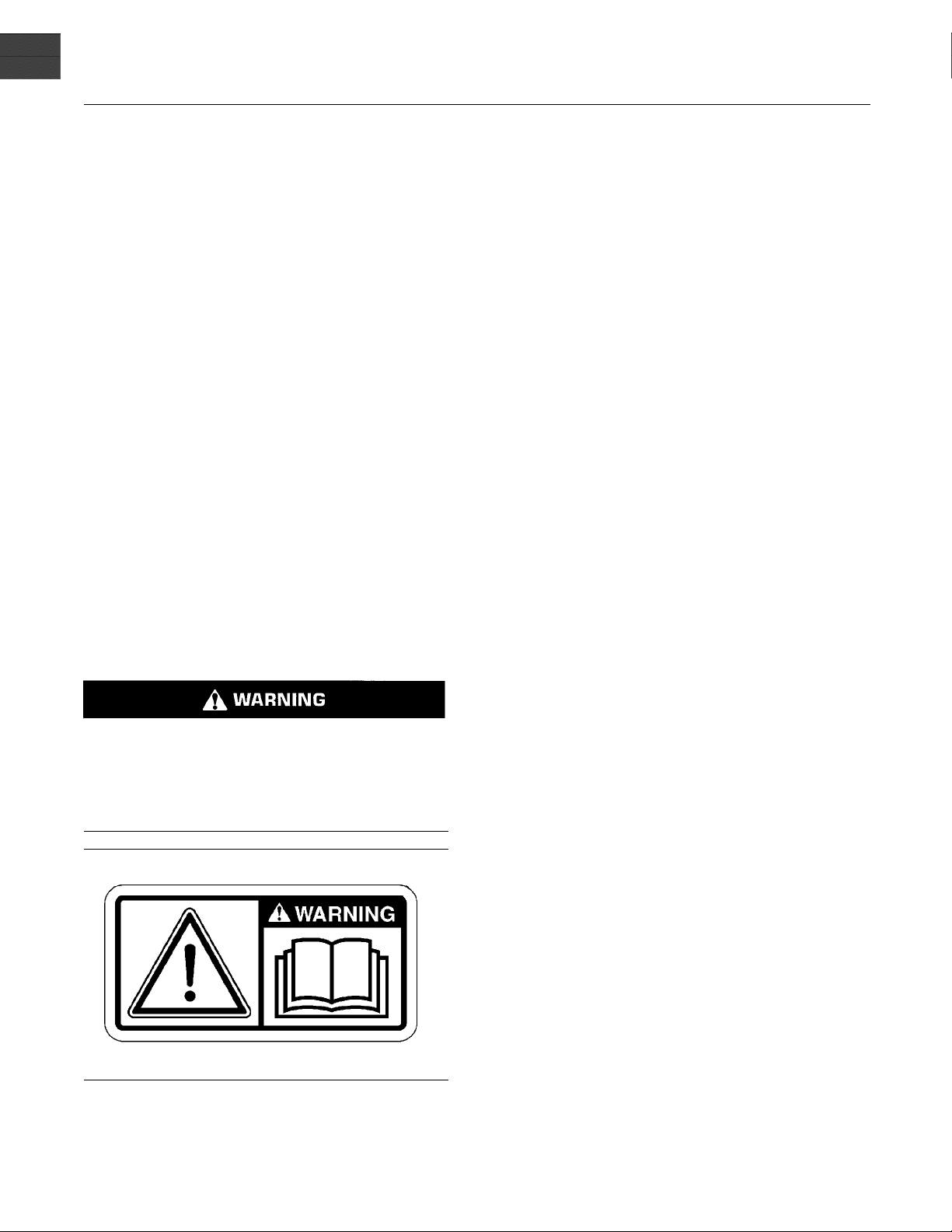
The hazards are identified by the “Safety Alert Symbol” and followed by a “Signal Word” such as
“DANGER”, “WARNING” or “CAUTION”. The Safety Alert “WARNING” label is shown below.
The meaning of this safety alert symbol is as follows:
Attention! Become Alert! Your Safety is Involved.
The message that appears under the warning explains the hazard and can be either written or
pictorially presented.
Operations that may cause product damage are identified by “NOTICE” labels on the product and in
this publication.
Perkins cannot anticipate every possible circumstance that might involve a potential hazard. The
warnings in this publication and on the product are, therefore, not all inclusive. If a tool, procedure,
work method or operating technique that is not specifically recommended by Perkins is used,
you must satisfy yourself that it is safe for you and for others. You should also ensure that the
product will not be damaged or be made unsafe by the operation, lubrication, maintenance or
repair procedures that you choose.
The information, specifications, and illustrations in this publication are on the basis of information that
was available at the time that the publication was written. The specifications, torques, pressures,
measurements, adjustments, illustrations, and other items can change at any time. These changes can
affect the service that is given to the product. Obtain the complete and most current information before
you start any job. Perkins dealers or Perkins distributors have the most current information available.
When replacement parts are required for this
product Perkins recommends using Perkins
replacement parts.
Failure to heed this warning can lead to premature failures, product damage, personal injury or
death.
Page 3

SEBU8172-02 3
Table of Contents
Table of Contents
Foreword ................................................................. 4
Safety Section
Safety Messages .................................................... 6
General Hazard Information ................................... 9
Burn Prevention .................................................... 10
Fire Prevention and Explosion Prevention ............. 11
Crushing Prevention and Cutting Prevention ........ 13
Mounting and Dismounting ................................... 13
High Pressure Fuel Lines ..................................... 13
Before Starting Engine .......................................... 15
Engine Starting ..................................................... 15
Engine Stopping ................................................... 16
Maintenance In
Warranty Sect
Warranty Information .......................................... 105
terval Schedule ............................ 69
ion
Index Section
Index ................................................................... 106
Electrical System .................................................. 16
Engine Electronics ................................................ 17
Product Information Section
Model Views ......................................................... 18
Product Identification Information ........................ 23
Operation Section
Lifting and Storage ................................................ 25
Gauges and Indicators .......................................... 27
Features and Controls .......................................... 29
Engine Diagnostics ............................................... 36
Engine Starting ..................................................... 40
Engine Operation .................................................. 43
Engine Stopping ................................................... 44
Cold Weather Operation ....................................... 46
Maintenance Section
Refill Capacities .................................................... 50
Maintenance Recommendations .......................... 67
Page 4

4 SEBU8172-02
Foreword
Foreword
Literature Information
This manual co
lubrication and maintenance information. This
manual should be stored in or near the engine area
in a literatu
study and keep it with the literature and engine
information.
English is the primary language for all Perkins
publications. The English used facilitates translation
and consist
Some photographs or illustrations in this manual
show detai
from your engine. Guards and covers may have
been removed for illustrative purposes. Continuing
improveme
may have caused changes to your engine which are
not included in this manual. Whenever a question
arises re
consult with your Perkins dealer for the latest
available information.
ntains safety, operation instructions,
re holder or literature storage area. Read,
ency in electronic media delivery.
ls or attachments that may be different
nt and advancement of product design
garding your engine, or this manual, please
Use fuel consum
intervals. Calendar intervals shown (daily, annually,
etc.) may be used instead of service meter intervals
if they provid
approximate the indicated service meter reading.
Recommended
appropriate intervals as indicated in the Maintenance
Interval Schedule. The actual operating environment
of the engin
Schedule. Therefore, under extremely severe,
dusty, wet or freezing cold operating conditions,
more freque
specified in the Maintenance Interval Schedule may
be necessary.
The maintenance schedule items are organized for
a preventive maintenance management program. If
the preven
periodic tune-up is not required. The implementation
of a preventive maintenance management program
should mi
avoidances resulting from reductions in unscheduled
downtime and failures.
nimize operating costs through cost
ption or service hours to determine
e more convenient schedules and
service should be performed at the
e also governs the Maintenance Interval
nt lubrication and maintenance than is
tive maintenance program is followed, a
Maintenance Intervals
Safety
This safety section lists basic safety precautions.
In addition, this section identifies hazardous,
g situations. Read and understand the basic
warnin
precautions listed in the safety section before
operating or performing lubrication, maintenance and
on this product.
repair
Opera
Operating techniques outlined in this manual are
basic
techniques required to operate the engine more
efficiently and economically. Skill and techniques
deve
engine and its capabilities.
The o
Photographs and illustrations guide the operator
through procedures of inspecting, starting, operating
and
discussion of electronic diagnostic information.
tion
. They assist with developing the skills and
lop as the operator gains knowledge of the
peration section is a reference for operators.
stopping the engine. This section also includes a
Maintenance
e maintenance section is a guide to engine care.
Th
The illustrated, step-by-step instructions are grouped
by fuel consumption, service hours and/or calendar
me maintenance intervals. Items in the maintenance
ti
schedule are referenced to detailed instructions that
follow.
Perform maintenance on items at multiples of the
original requirement. Each level and/or individual
items in
depending upon your specific maintenance practices,
operation and application. We recommend that
the mai
displayed near the engine as a convenient reminder.
We also recommend that a maintenance record be
maint
See the section in the Operation and Maintenance
Manua
regarding documents that are generally accepted
as proof of maintenance or repair. Your authorized
Perkins dealer can assist you in adjusting your
maintena
operating environment.
each level should be shifted ahead or back
ntenance schedules be reproduced and
ained as part of the engine's permanent record.
l, “Maintenance Records” for information
chedule to meet the needs of your
nce s
Overhaul
Major engine overhaul details are not covered in the
Operation and Maintenance Manual except for the
erval and the maintenance items in that interval.
int
Major repairs are best left to trained personnel or
an authorized Perkins dealer. Your Perkins
ler offers a variety of options regarding overhaul
dea
programs. If you experience a major engine failure,
there are also numerous after failure overhaul options
ailable from your Perkins de
av
dealer for information regarding these options.
your
aler. Consult with
Page 5

SEBU8172-02 5
Foreword
California Proposition 65 Warning
Diesel engine exhaust and some of its constituents
are known to the State of California to cause cancer,
birth defects, and other reproductive harm.
Battery posts, terminals and related accessories
contain lead and lead compounds. Wash hands
after handling.
Page 6
6 SEBU8172-02
Safety Section
Safety Messages
Safety Section
i02864025
Safety Me ssages
There may be
engine. The exact location and a description of the
warning signs are reviewed in this section. Please
become fam
Ensure that all of the warning signs are legible. Clean
the warnin
the words cannot be read or if the illustrations are
not visible. Use a cloth, water, and soap to clean
the warni
other harsh chemicals. Solvents, gasoline, or harsh
chemicals could loosen the adhesive that secures the
warning
could drop off of the engine.
Replace
missing.Ifawarningsignisattachedtoapartofthe
engine that is replaced, install a new warning sign on
the rep
distributor can provide new warning signs.
lacement part. Your Perkins dealer or your
several specific warning signs on your
iliar with all warning signs.
g signs or replace the warning signs if
ng signs. Do not use solvents, gasoline, or
signs. The warning signs that are loosened
any warning sign that is damaged or
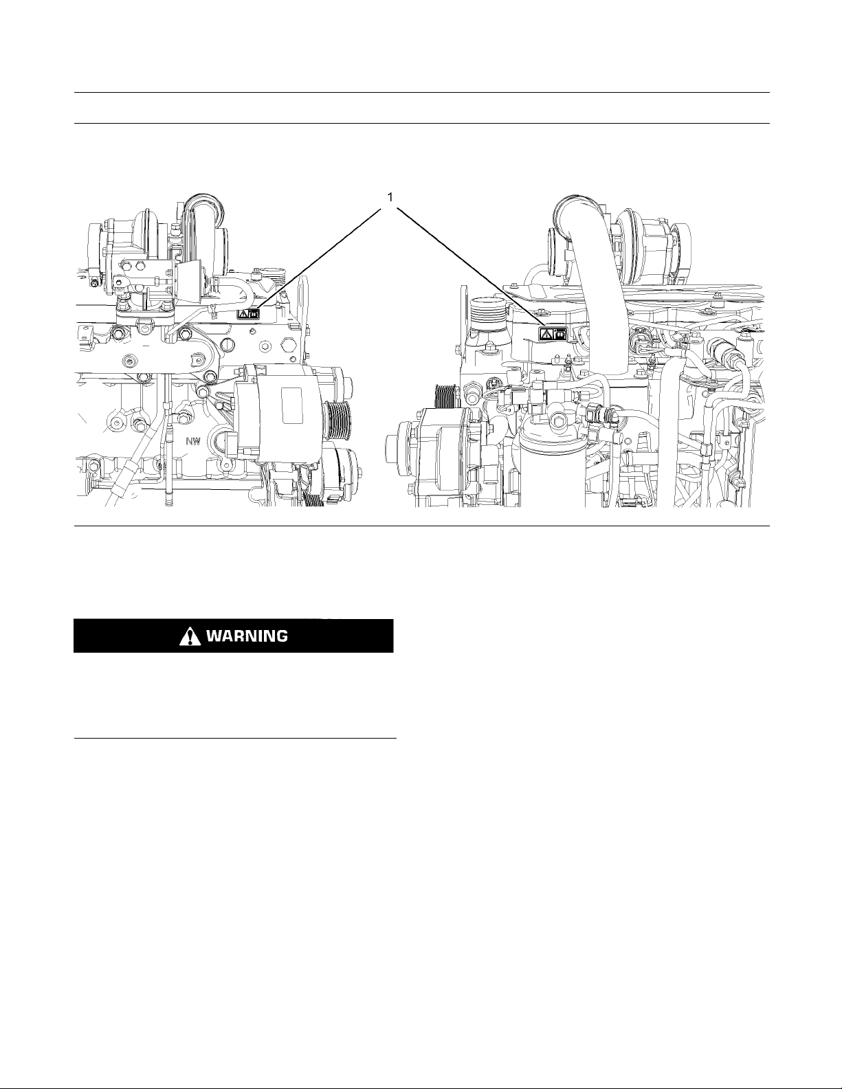
The Universal W
sides of the valve mechanism cover base. Refer to
illustration 1.
arning label (1) is located on both
(1) Universal Warning
Do not operate or work on this equipment unless
ave read and understand the instructions
you h
and warnings in the Operation and Maintenance
Manuals. Failure to follow the instructions or
the warnings could result in serious injury
heed
or death.
Illustration 1
ypical example
T
g01154807
Page 7
SEBU8172-02 7
Safety Section
Safety Messages
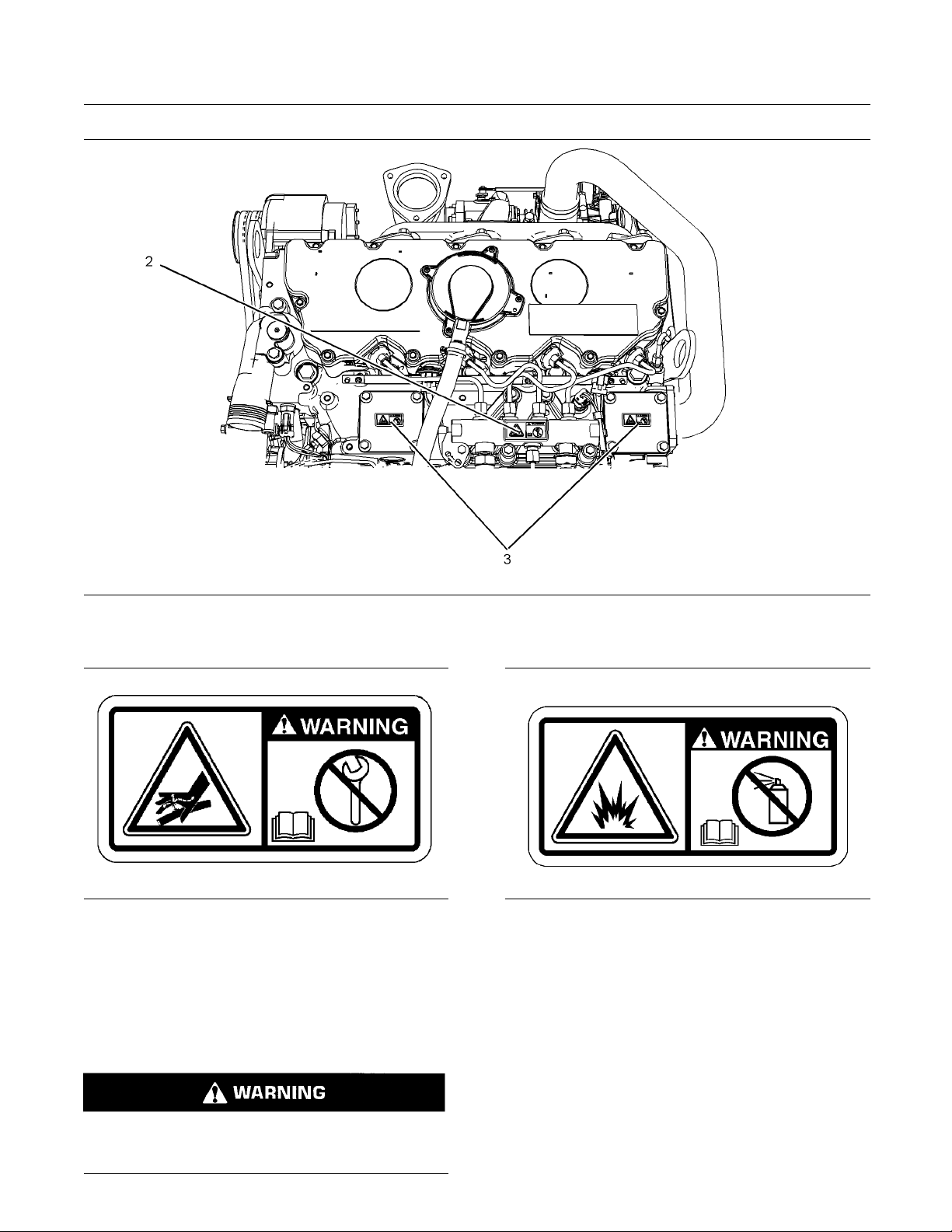
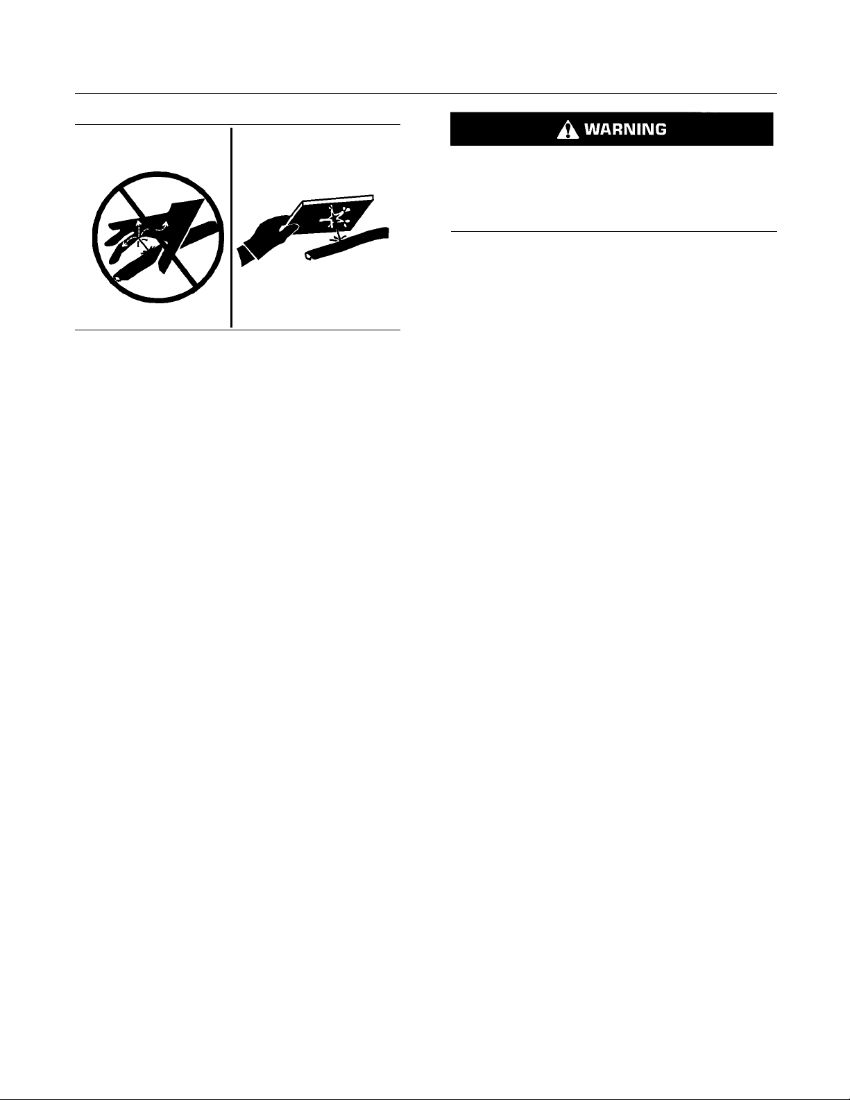
Illustration 2
ersal warning
(1) Univ
(2) Han
d (High Pressure)
Contact with high pressure fuel may cause fluid
penetration and burn hazards. High pressure fu-
ay may cause a fire hazard. Failure to fol-
el spr
low these inspection, maintenance and service instructions may cause personal injury or death.
g01268960
Page 8
8 SEBU8172-02
Safety Section
Safety Messages
Illustration 3
(2) Hand
Illustration 4
Typical example
(High Pressure)
(3) Ethe
r
g01154858
The warning label for the Hand (High Pressure) (2)
is located on the top of the fuel manifold. Refer to
illustration 4.
(3) Ether
g01426636
Illustration 5
Typical example
g01154809
The ether warning label (3) is located on the cover of
the inlet manifold. Refer to illustration 4.
Note: The location of this label will depend on the
application of the engine.
Do not use aerosol types of starting aids such as
ether. Such use could result in an explosion and
personal injury.
Page 9
SEBU8172-02 9
Safety Section
General Hazard Information
i02328435
General Hazard Information
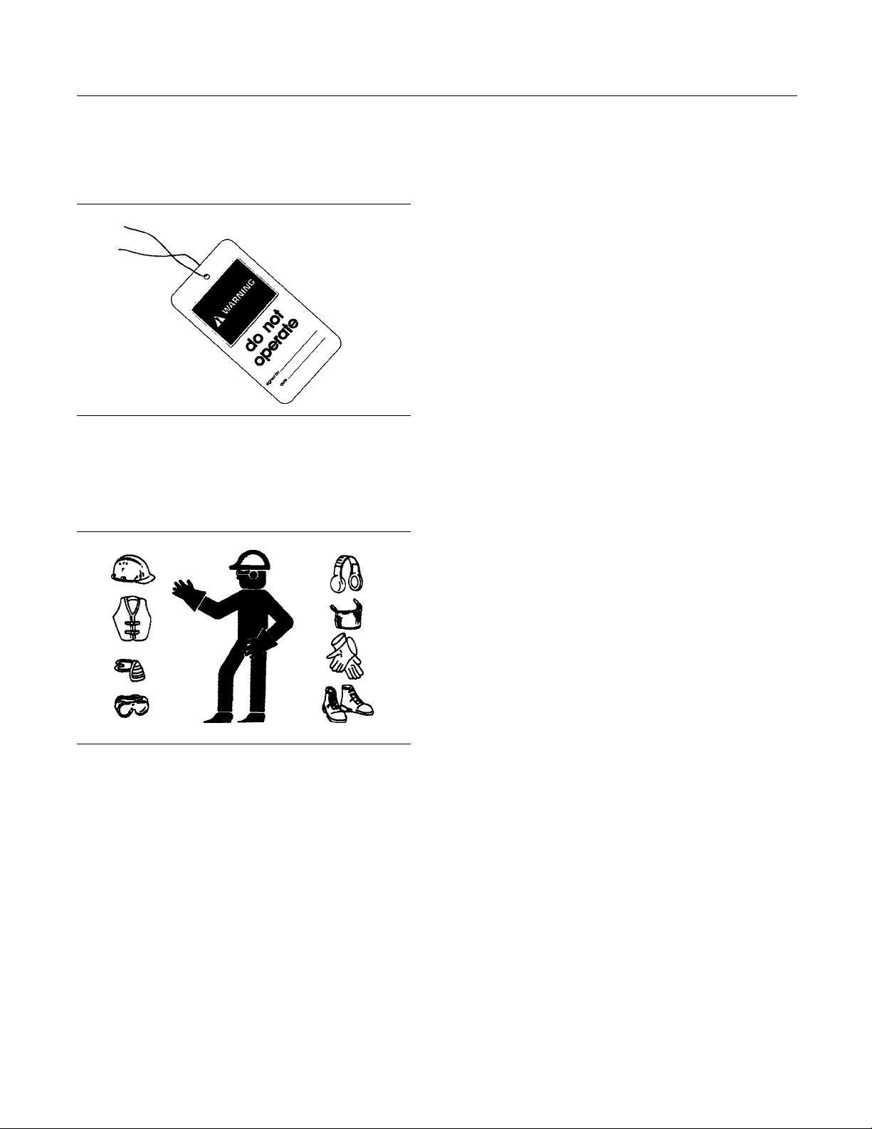
Illustration 6
Attach a “Do Not Operate” warning tag or a similar
warning tag to the start switch or to the controls
before y
ou service the equipment or before you
repair the equipment.
g0010454
Report all nece
ssary repairs.
Do not allow unauthorized personnel on the
equipment.
Ensure that the power supply is disconnected before
youworkonth
e bus bar or the glow plugs.
Perform maintenance on the engine with the
equipment i
ntheservicingposition.Refertothe
OEM information for the procedure for placing the
equipment in the servicing position.
Pressure Air and Water
Pressurized air and/or water can cause debris
and/or hot water to be blown out. This could result in
personal i
5
The direct application of pressurized air or
pressuri
injury.
When pres
cleaning, wear protective clothing, protective shoes,
and eye protection. Eye protection includes goggles
or a prot
njury.
zed water to the body could result in personal
surized air and/or water is used for
ective face shield.
02020
Illustration 7
g007
Wear a hard hat, protective glasses, and other
protective equipment, as required.
Do not wear loose clothing or jewelry that can snag
on controls or on other parts of the engine.
Make sure that all protective guards and all covers
are secured in place on the engine.
Keep the engine free from foreign material. Remove
debris, oil, tools, and other items from the deck, from
lkways, and from steps.
wa
The maximum air pressure for cleaning purposes
must be b
elow 205 kPa (30 psi). The maximum
water pressure for cleaning purposes must be below
275 kPa (40 psi).
Fluid Penetration
Pressure can be trapped in the hydraulic circuit long
after the engine has been stopped. The pressure can
hydraulic fluid or items such as pipe plugs to
cause
escape rapidly if the pressure is not relieved correctly.
Do not
until pressure has been relieved or personal injury
may occur. Do not disassemble any hydraulic
comp
or personal injury may occur. Refer to the OEM
information for any procedures that are required to
reli
remove any hydraulic components or parts
onents or parts until pressure has been relieved
eve the hydraulic pressure.
Never put maintenance fluids into glass containers.
rain all liquids into a suitable container.
D
Obey all local regulations for the disposal of liquids.
Use all cleaning solutions with care.
Page 10
10 SEBU8172-02
Safety Section
Burn Prevention
Contact with high pressure fuel may cause fluid
penetration and burn hazards. High pressure fuel spray may cause a fire hazard. Failure to follow these inspection, maintenance and service instructions may cause personal injury or death.
After the engine has stopped, you must wait for 60
seconds in order to allow the fuel pressure to be
purged from the high pressure fuel lines before any
service or repair is performed on the engine fuel lines.
Illustration 8
Always use a board or cardboard when you check
for a leak. Leaking fluid that is under pressure can
penetrate body tissue. Fluid penetration can cause
serious injury and possible death. A pin hole leak can
cause severe injury. If fluid is injected into your skin,
you must get treatment immediately. Seek treatment
from a doctor that is familiar with this type of injury.
g00687600
Containing Fluid Spillage
Care must be taken in order to ensure that fluids
are contained during performance of inspection,
maintenance, testing, adjusting and repair of the
engine. Make provision to collect the fluidwitha
suitable container before any compartment is opened
or before any component is disassembled.
Only use the tools that are suitable for collecting
•
fluids and equipment that is suitable for collecting
fluids.
Only use the tools that are suitable for containing
•
fluids and equipment that is suitable for containing
fluids.
Allow the pressure to be purged in the air system, in
the hydraulic system, in the lubrication system, or in
the cooling system before any lines, fittings or related
items are disconnected.
Coolant
When the engine is at operating temperature, the
engine coolant is hot. The coolant is also under
pressure. The radiator and all lines to the heaters or
to the engine contain hot coolant.
Any contact with hot coolant or with steam can cause
severe burns. Allow cooling system components to
cool before the cooling system is drained.
Check the coolant level after the engine has stopped
and the engine has been allowed to cool.
Ensure that the filler cap is cool before removing the
filler cap. The filler cap must be cool enough to touch
with a bare hand. Remove the filler cap slowly in
order to relieve pressure.
Cooling system conditioner contains alkali. Alkali can
cause personal injury. Do not allow alkali to contact
the skin, the eyes, or the mouth.
Obey all local regulations for the disposal of liquids.
i02334785
n P revention
Bur
Do not touch any part of an operating engine.
Allow the engine to cool before any maintenance is
rformed on the engine.
pe
Oils
Hot oil and hot lubricating components can cause
personal injury. Do not allow hot oil to contact the
skin. Also, do not allow hot components to contact
the skin.
Batteries
Electrolyte is an acid. Electrolyte can cause personal
injury. Do not allow electrolyte to contact the skin or
the eyes. Always wear protective glasses for servicing
batteries. Wash hands after touching the batteries
and connectors. Use of gloves is recommended.
Page 11
SEBU8172-02 11
Safety Section
Fire Prevention and Explosion Prevention
i04823662
Fire Prevention and Explosio n
Prevention
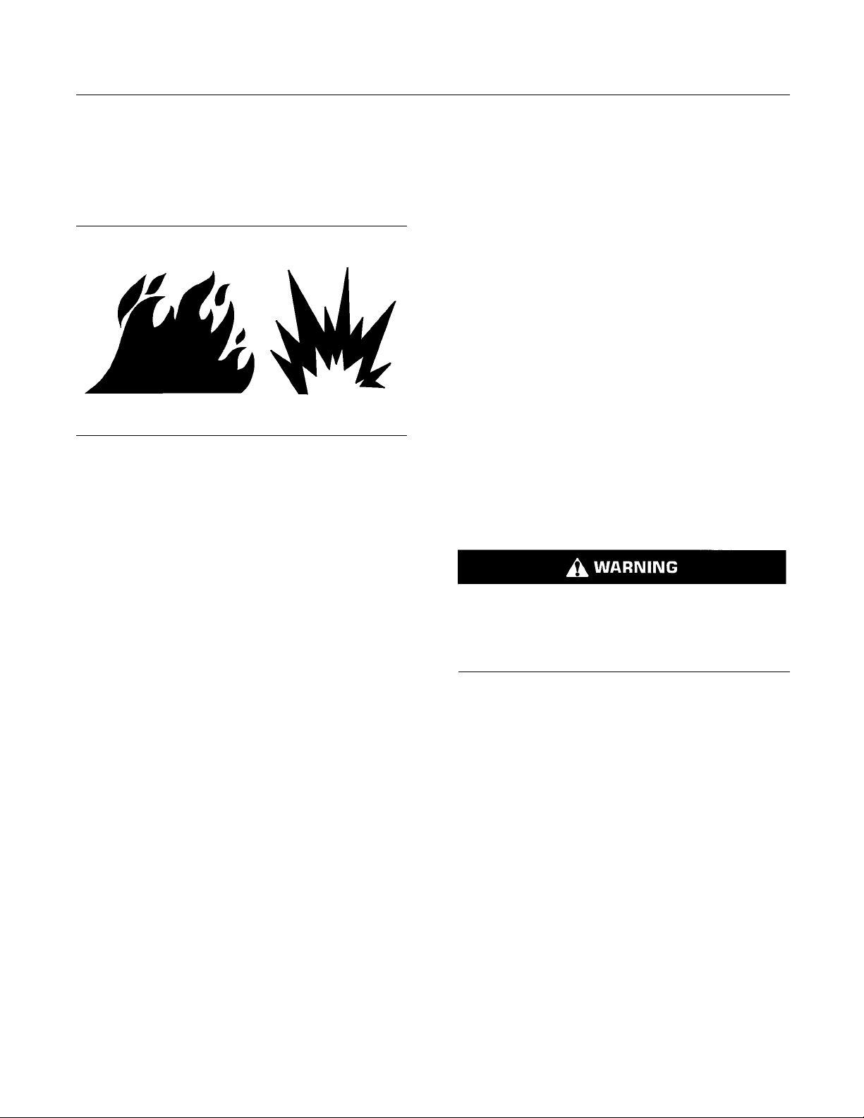
tion 9
Illustra
All fuels, most lubricants, and some coolant mixtures
are flamm
Flammable fluids that are leaking or spilled onto hot
surface
a fire. Fire may cause personal injury and property
damage.
After the emergency stop button is operated, ensure
that you allow 15 minutes, before the engine covers
are rem
Determine whether the engine will be operated in an
envir
drawn into the air inlet system. These gases could
cause the engine to overspeed. Personal injury,
prop
If the application involves the presence of combustible
gase
Perkins distributor for additional information about
suitable protection devices.
Remove all flammable combustible materials or
conductive materials such as fuel, oil, and debris from
the
materials or conductive materials to accumulate on
the engine.
able.
s or onto electrical components can cause
oved.
onment that allows combustible gases to be
erty damage, or engine damage could result.
s, consult your Perkins dealer and/or your
engine. Do not allow any flammable combustible
g00704000
Exhaust shield
components from oil or fuel spray in a line, a tube,
or a seal failure. Exhaust shields must be installed
correctly.
Do not weld on lines or tanks that contain flammable
fluids. Do not
flammable fluid. Clean any such lines or tanks
thoroughly with a nonflammable solvent prior to
welding or fl
Wiring must be kept in good condition. Ensure that
all electri
attached. Check all electrical wires daily. Repair any
wires that are loose or frayed before you operate the
engine. Cl
all electrical connections.
Eliminate
Do not use any wires or cables that are smaller than
the recommended gauge. Do not bypass any fuses
and/or ci
Arcing or sparking could cause a fire. Secure
connecti
maintained battery cables will help to prevent arcing
or sparking.
Contac
penetration and burn hazards. High pressure fuel spray may cause a fire hazard. Failure to follow the
structions may cause personal injury or death.
After
order to allow the fuel pressure to be purged from the
high-pressure fuel lines before any service or repair
is pe
Ensure that the engine is stopped. Inspect all lines
and h
route all hoses. The lines and hoses must have
adequate support and secure clamps.
Properly install oil filters and fuel filters. The filter
housings must be tightened to the correct torque.
Ref
more information.
t with high pressure fuel may cause fluid
se inspection, maintenance and service in-
the engine has stopped, wait for 60 seconds in
rformed on the engine fuel lines.
oses for wear or for deterioration. Properly
er to the Disassembly and Assembly manual for
s (if equipped) protect hot exhaust
flame cut lines or tanks that contain
ame cutting.
cal wires are correctly routed and securely
ean all electrical connections and tighten
all wiring that is unattached or unnecessary.
rcuit breakers.
ons, recommended wiring, and correctly
Store fuels and lubricants in correctly marked
containers away from unauthorized persons. Store
ly rags and any flammable materials in protective
oi
containers. Do not smoke in areas that are used for
storing flammable materials.
Do not expose the engine to any flame.
Page 12
12 SEBU8172-02
Safety Section
Fire Prevention and Explosion Prevention
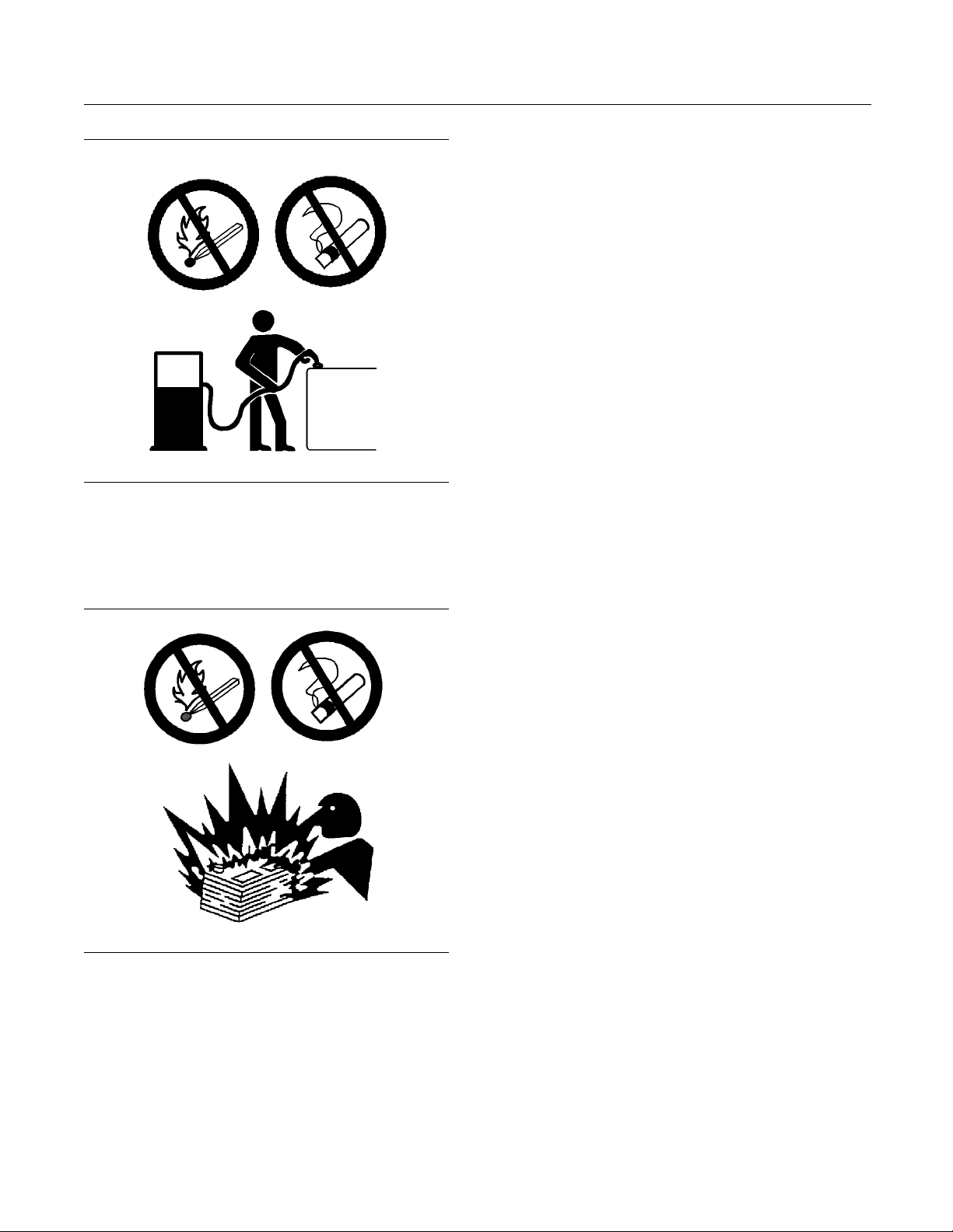
Illustration 10
Use caution when you are refueling an engine. Do
not smoke while you are refueling an engine. Do not
refuel an engine near open flames or sparks. Always
stop the engine before refueling.
g00704059
Incorrect jump
an explosion that can result in injury. Refer to
the Operation Section of this manual for specific
instructions
Do not charge a frozen battery.Charging a frozen
battery may c
The batteries must be kept clean. The covers
(if equippe
recommended cables, connections, and battery box
covers when the engine is operated.
er cable connections can cause
.
ause an explosion.
d) must be kept on the cells. Use the
Fire Extinguisher
Make sure that a fire extinguisher is available. Be
familiar with the operation of the fire extinguisher.
Inspect th
extinguisher regularly. Obey the recommendations
on the instruction plate.
e fire extinguisher and service the fire
Lines, Tubes, and Hoses
Do not bend high-pressure lines. Do not strike
high-pressure lines. Do not install any lines that are
damaged
.
Illustration 11
Gases from a battery can explode. Keep any open
flames or sparks away from the top of a battery. Do
not smoke in battery charging areas.
g02298225
Leaks can cause fires. Consult your Perkins dealer
or your P
Replace the parts if any of the following conditions
are pre
High-pressure fuel line or lines are removed.
•
End fittings are damaged or leaking.
•
Outer
•
Wires are exposed.
•
Outer coverings are ballooning.
•
Flex
•
Outer covers have embedded armoring.
•
End fittings are displaced.
•
Mak
are installed correctly in order to prevent vibration,
rubbing against other parts, and excessive heat.
erkins distributor for replacement parts.
sent:
coverings are chafed or cut.
ible parts of the hoses are kinked.
e sure that all clamps, guards, and heat shields
Never check the battery charge by placing a metal
object across the terminal posts. Use a voltmeter or
ahydrometer.
Page 13

SEBU8172-02 13
Safety Section
Crushing Prevention and Cutting Prevention
i02143194
Crushing Prevention and
Cutting Preve
Support the component correctly when work beneath
the component is performed.
Unless other maintenance instructions are provided,
never attempt adjustments while the engine is
running.
Stay clear of all rotating parts and of all moving
parts. Lea
is performed. After the maintenance is performed,
reinstall the guards.
Keep objects away from moving fan blades. The fan
blades will throw objects or cut objects.
When objects are struck, wear protective glasses in
order to avoid injury to the eyes.
Chips or other debris may fly off objects when objects
are struck. Before objects are struck, ensure that no
one will
ve the guards in place until maintenance
be injured by flying debris.
ntion
i02861106
High Pressure Fuel Lines
Contact with high pressure fuel may cause fluid
penetration and burn hazards. High pressure fuel spray may
low these inspection, maintenance and service instructions may cause personal injury or death.
cause a fire hazard. Failure to fol-
i02235492
Mounting and Dismounting
Inspect the steps, the handholds, and the work area
before mounting the engine. Keep these items clean
and keep these items in good repair.
Mount the engine and dismount the engine only at
locations that have steps and/or handholds. Do not
climb on the engine, and do not jump off the engine.
Face the engine in order to mount the engine or
dismount the engine. Maintain a three-point contact
with the steps and handholds. Use two feet and one
hand or use one foot and two hands. Do not use any
controls as handholds.
Do not stand on components which cannot support
your weight. Use an adequate ladder or use a work
platform. Secure the climbing equipment so that the
equipment will not move.
Do not carry tools or supplies when you mount the
engine or when you dismount the engine. Use a hand
line to raise and lower tools or supplies.
Page 14
14 SEBU8172-02
Safety Section
High Pressure Fuel Lines
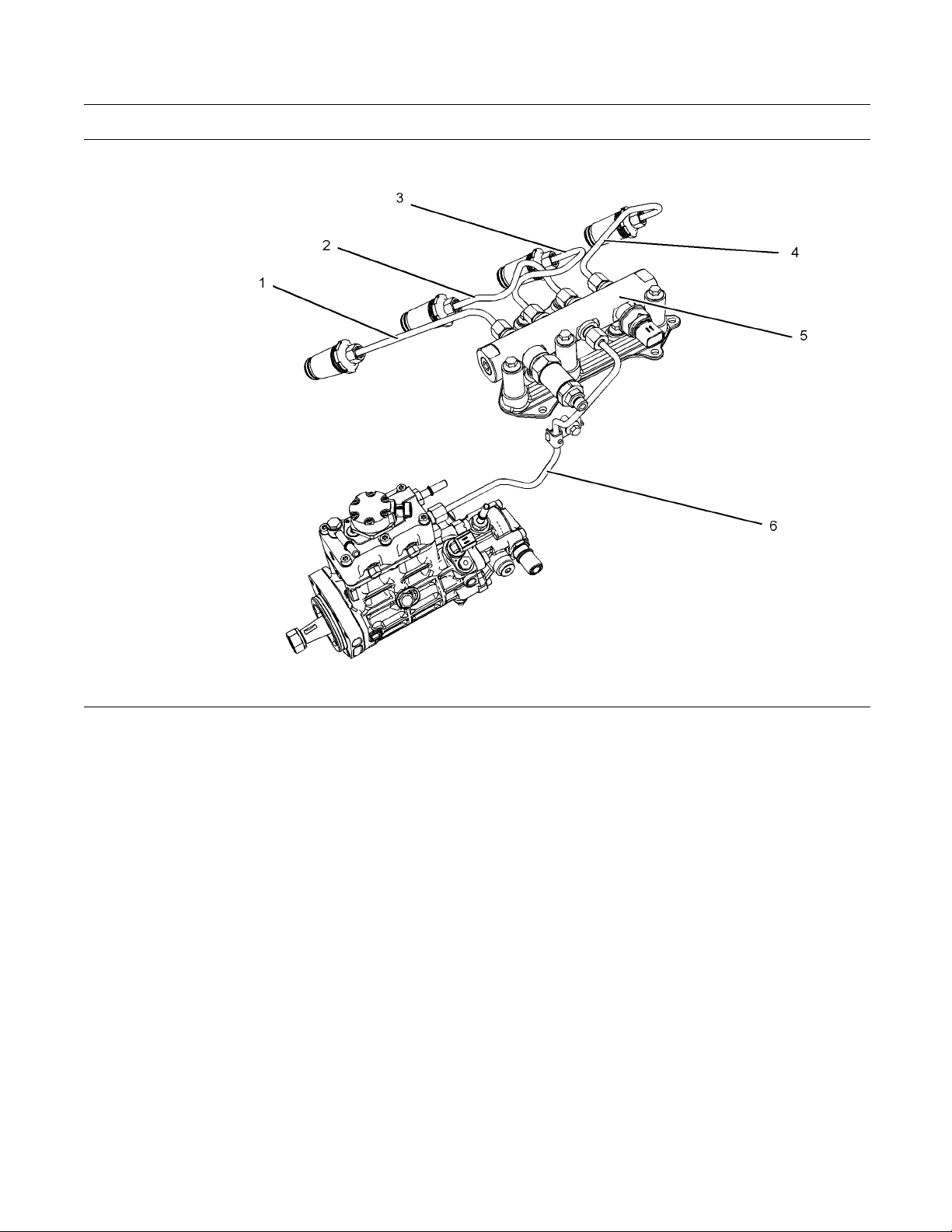
Illustration 12
(1)Highpressureline
(2)Highpressureline
(3) High pre ssure line
(4) High pre ssure line
The high pressure fuel lines are the fuel lines that
are between the high pressure fuel pump and the
high pressure fuel manifold and the fuel lines that are
between the fuel manifold and cylinder head. These
fuel lines are different from fuel lines on other fuel
systems.
This is because of the following differences:
The high pressure fuel lines are constantly charged
•
with high pressure.
The internal pressures of the high pressure fuel
•
lines are higher than other types of fuel system.
The high pressure fuel lines are formed to shape
•
and then strengthened by a special process.
Do not step on the high pressure fuel lines. Do not
deflect the high pressure fuel lines. Do not bend or
strike the high pressure fuel lines. Deformation or
damage of the high pressure fuel lines may cause a
point of weakness and potential failure.
g01425090
(5) High pressure fuel manifold (rail)
(6) High pressure line
Do not check the high pressure fuel lines with the
engine or the starting motor in operation. After the
engine has stopped allow 60 seconds to pass in order
to allow the pressure to be purged before any service
or repair is performed on the engine fuel lines.
Do not loosen the high pressure fuel lines in order
to remove air from the fuel system. This procedure
is not required.
Visually inspect the high pressure fuel lines before
the engine is started. This inspection should be each
day.
If you inspect the engine in operation, always use
the proper inspection procedure in order to avoid
a fluid penetration hazard. Refer to Operation and
Maintenance Manual, “General Hazard Information”.
Inspect the high pressure for the following:
•
damage, deformation, a nick, a cut, a crease, or
adent
Page 15
SEBU8172-02 15
Safety Section
Before Starting Engine
Do not operate t
•
isaleakdonottightentheconnectioninorder
to stop the leak. The connection must only be
tightened to t
Disassembly and Assembly Manual, “Fuel Injection
Lines - Remove and Fuel Injection Lines - Install”.
If the high pressure fuel lines are torqued correctly
•
and the high pressure fuel lines are leaking the
high pressu
Ensure that all clips on the high pressure fuel lines
•
areinplace
that are damaged, missing or clips that are loose.
Do not atta
•
fuel lines.
Loosened h
•
replaced. Also removed high pressure fuel lines
must be replaced. Refer to Disassembly and
Assembly
he engine with a fuel leak. If there
he recommended torque. Refer to
re fuel lines must be replaced.
. Do not operate the engine with clips
ch any other item to the high pressure
igh pressure fuel lines must be
Manual, “ Fuel Injection Lines - Install”.
i02813489
Before Starting Engine
See the Service
adjustments.
Manual for repairs and for
i02251260
Engine Starting
Do not use aerosol types of starting aids such as
ether. Such use could result in an explosion and
personal injury.
If a warning tag is attached to the engine start switch
or to the controls DO NOT start the engine or move
the controls. Consult with the person that attached
the warning tag before the engine is started.
All protective guards and all protective covers must
be installed if the engine must be started in order
to perform service procedures. To help prevent an
accident that is caused by parts in rotation, work
around the parts carefully.
Before the initial start-up of an engine that is new,
serviced or repaired, make provision to shut the
engine off, in order to stop an overspeed. This may
be accomplished by shutting off the air and/or fuel
supply to the engine.
Overspeed shutdown should occur automatically for
engines that are controlled electronically. If automatic
shutdown does not occur, press the emergency stop
button in order to cut the fuel and/or air to the engine.
Inspect the engine for potential hazards.
Before starting the engine, ensure that no one is on,
underneath, or close to the engine. Ensure that the
area is free of personnel.
If equipped, ensure that the lighting system for the
engine is suitable for the conditions. Ensure that all
lights work correctly, if equipped.
All protective guards and all protective covers must
be installed if the engine must be started in order
to perform service procedures. To help prevent an
accident that is caused by parts in rotation, work
around the parts carefully.
Do not bypass the automatic shutoff circuits. Do not
disable the automatic shutoff circuits. The circuits are
provided in order to help prevent personal injury. The
circuits are also provided in order to help prevent
engine damage.
Start the engine from the operator's compartment or
from the engine start switch.
Always start the engine according to the procedure
that is described in the Operation and Maintenance
Manual, “Engine Starting” topic in the Operation
Section. Knowing the correct procedure will help to
prevent major damage to the engine components.
Knowing the procedure will also help to prevent
personal injury.
To ensure that the jacket water heater (if equipped)
and/or the lube oil heater (if equipped) is working
correctly, check the water temperature gauge
and/or the oil temperature gauge during the heater
operation.
Engine exhaust contains products of combustion
which can be harmful to your health. Always start the
engine and operate the engine in a well ventilated
area. If the engine is started in an enclosed area,
vent the engine exhaust to the outside.
Note: The engine is equipped with a device for cold
starting. If the engine will be operated in very cold
conditions, then an extra cold starting aid may be
required. Normally, the engine will be equipped with
the correct type of starting aid for your region of
operation.
These engines are equipped with a glow plug starting
aid in each individual cylinder that heats the intake
air in order to improve starting.
Page 16
16 SEBU8172-02
Safety Section
Engine Stopping
i02234873
Engine Stopping
Stop the engin
the Operation and Maintenance Manual, “Engine
Stopping (Operation Section)” in order to avoid
overheating
the engine components.
Use the Emer
in an emergency situation. Do not use the Emergency
Stop Button for normal engine stopping. After an
emergency
problem that caused the emergency stop has been
corrected.
Stop the engine if an overspeed condition occurs
during the initial start-up of a new engine or an engine
that has b
To stop an electronically controlled engine, cut the
power to t
to the engine.
e according to the procedure in
of the engine and accelerated wear of
gency Stop Button (if equipped) ONLY
stop, DO NOT start the engine until the
een overhauled.
he engine and/or shutting off the air supply
i02234878
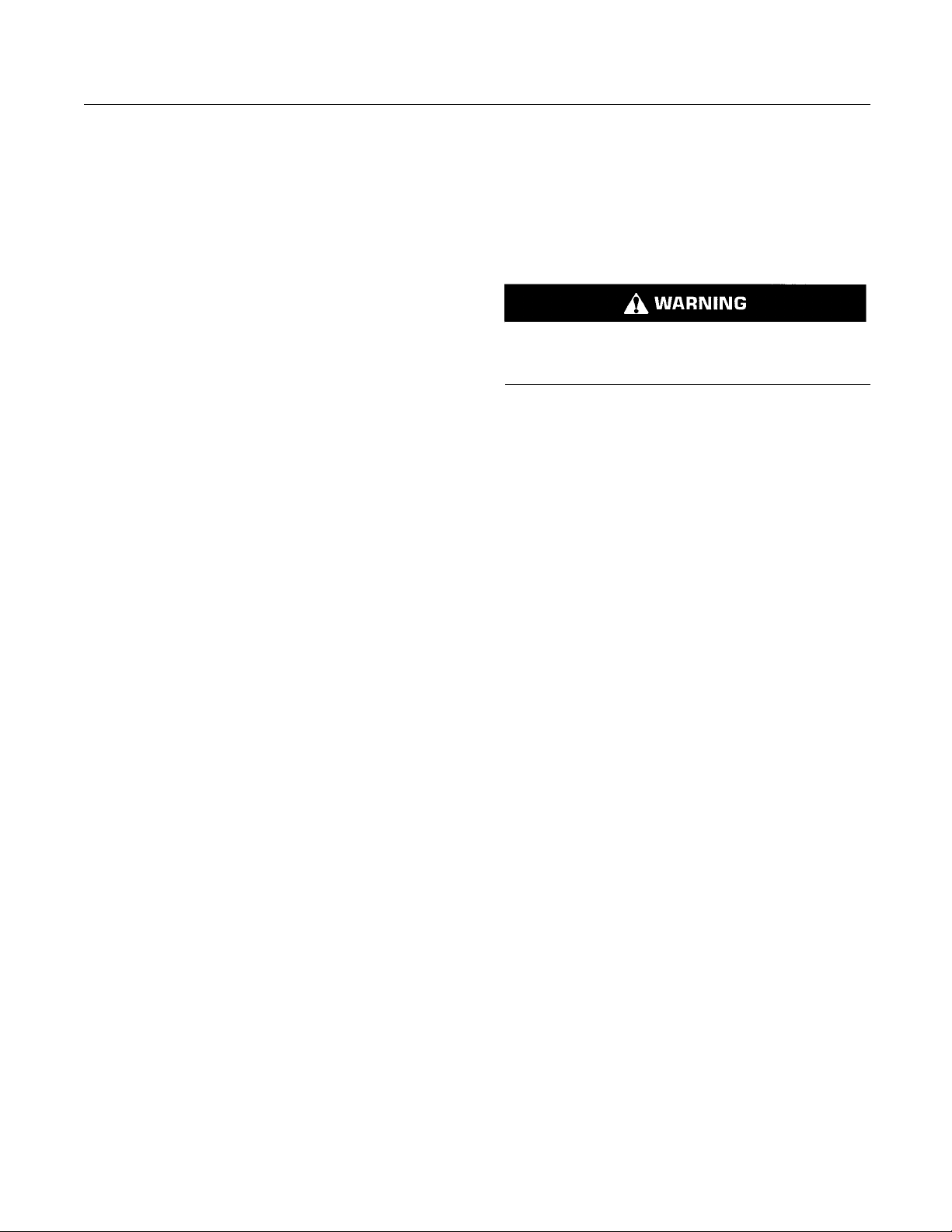
Grounding Practices
Illustration 13
Typical example
(1) Starting motor to engine block
(2) Ground to starting m otor
(3) Ground to battery
g01162916
Electrical System
Never disconnect any charging unit circuit or battery
circuit cable from the battery when the charging unit
is operating. A spark can cause the combustible
gases that are produced by some batteries to ignite.
To help prevent sparks from igniting combustible
gases that are produced by some batteries, the
negative “−” cable should be connected last from the
external power source to the negative “−” terminal
of the starting motor. If the starting motor is not
equipped with a negative “−” terminal, connect the
cable to the engine block.
Check the electrical wires daily for wires that
are loose or frayed. Tighten all loose electrical
connections before the engine is started. Repair all
frayed electrical wires before the engine is started.
See the Operation and Maintenance Manual for
specific starting instructions.
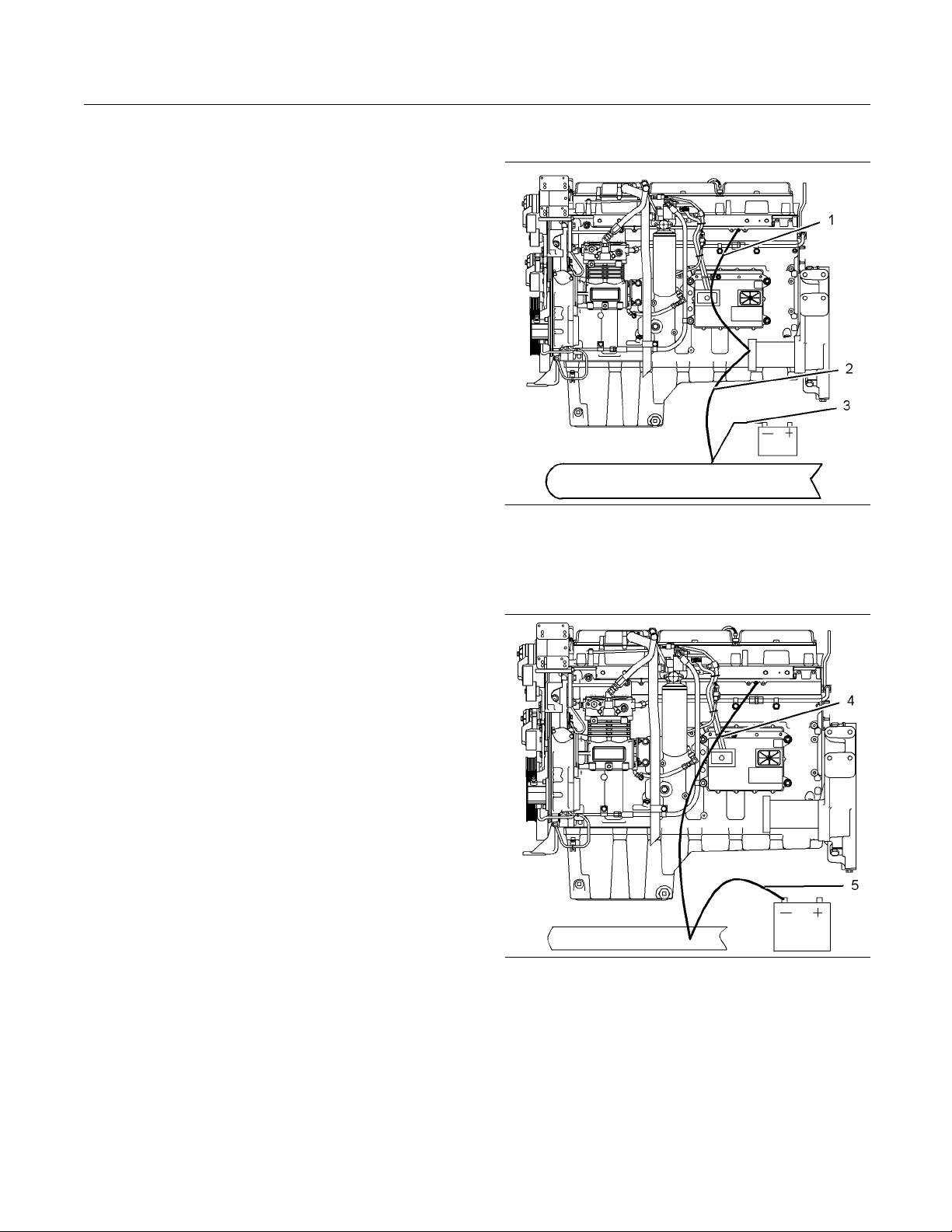
Illustration 14
Typical example
(4) Ground to engine
(5) Ground to battery
g01162918
Correct grounding for the engine electrical system
is necessary for optimum engine performance
and reliability. Incorrect grounding will result in
uncontrolled electrical circuit paths and in unreliable
electrical circuit paths.
Page 17
SEBU8172-02 17
Safety Section
Engine Electronics
Uncontrolled e
damage to the crankshaft bearing journal surfaces
and to aluminum components.
Engines that are installed without engine-to-frame
ground straps can be damaged by electrical
discharge.
To ensure that the engine and the engine electrical
systems fun
ground strap with a direct path to the battery must be
used. This path may be provided by way of a direct
engine grou
The connections for the grounds should be tight and
free of cor
grounded to the negative “-” battery terminal with
a wire that is adequate to handle the full charging
current of
The power supply connections and the ground
connecti
be from the isolator to the battery.
lectrical circuit paths can result in
ction correctly, an engine-to-frame
nd to the frame.
rosion. The engine alternator must be
the alternator.
ons for the engine electronics should always
i02650954
Engine Electronics
Derate
•
Shutdown
•
The following monitored engine operating conditions
have the ability to limit engine speed and/or the
engine power
Engine Coolant Temperature
•
Engine Oil Pressure
•
Engine Spee
•
Intake Manifold Air Temperature
•
The Engine Monitoring package can vary for different
engine models and different engine applications.
However, t
monitoring control will be similar for all engines.
Note: Man
modules that are available for Perkins Engines will
work in unison with the Engine Monitoring System.
Together
monitoring function for the specific engine application.
Refer to Troubleshooting for more information on the
Engine M
:
d/Timing
he monitoring system and the engine
y of the engine control systems and display
, the two controls will provide the engine
onitoring System.
Tampe
or the OEM wiring installation can be dangerous
and could result in personal injury or death and/or
engin
Electrical Shock Hazard. The electronic unit injectors use DC voltage. The ECM sends this voltage
to the electronic unit injectors. Do not come in
contact with the harness connector for the electronic unit injectors while the engine is operating.
Failure to follow this instruction could result in
personal injury or death.
This engine has a comprehensive, programmable
Engine Monitoring System. The Electronic Control
Module (ECM) has the ability to monitor the engine
operating conditions. If any of the engine parameters
extend outside an allowable range, the ECM will
initiate an immediate action.
The following actions are available for engine
monitoring control:
ring with the electronic system installation
e damage.
Warning
•
Page 18
18 SEBU8172-02
Product Information Section
Model Views
Product Information
Section
Model Views
i02861104
Model View Illustrations
The following model views show typical features
of the engine. Due to individual applications, your
engine may appear different from the illustrations.
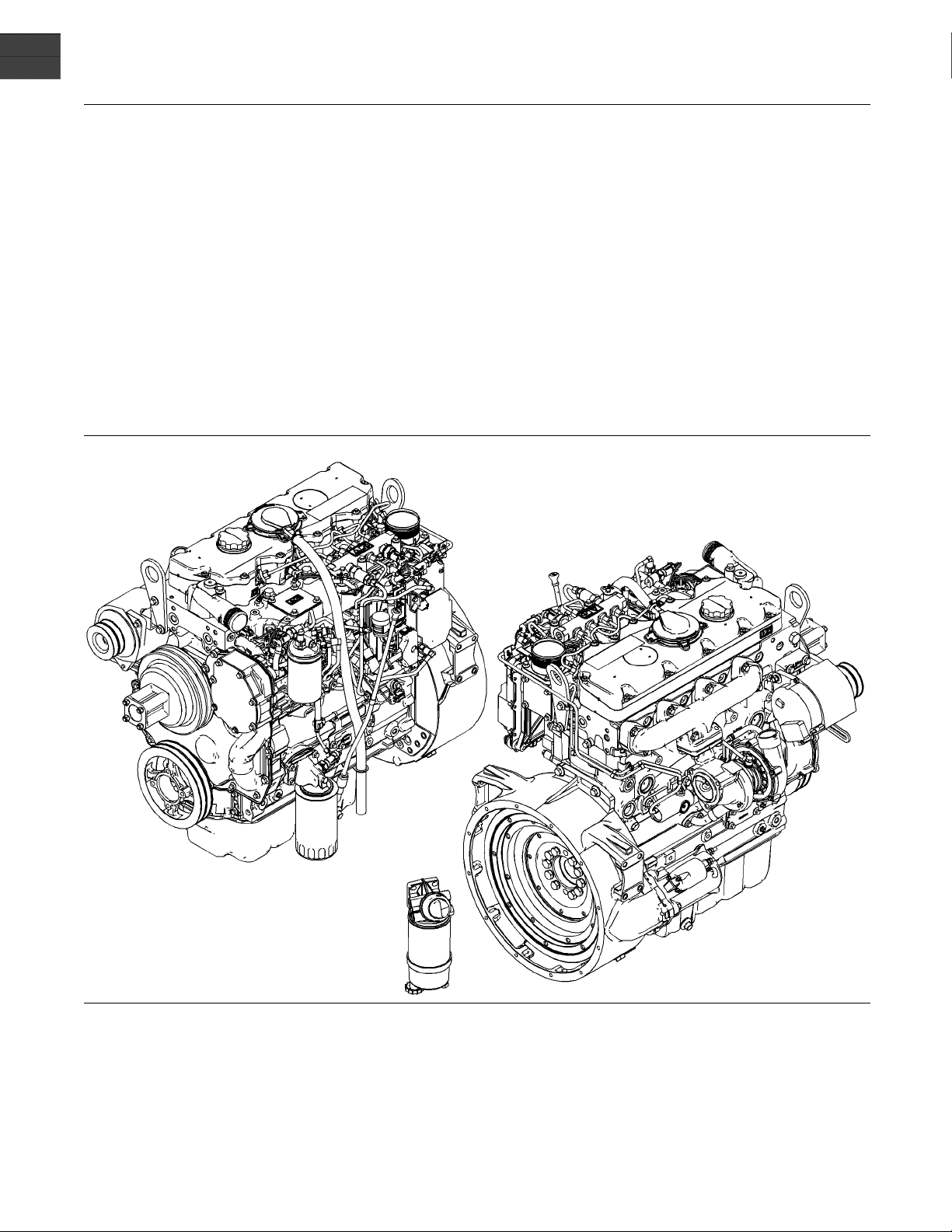
Illustration 15
The 1104D NJ engine is turbocharged and aftercooled.
g01425089
Page 19
SEBU8172-02 19
Product Information Section
Model Views
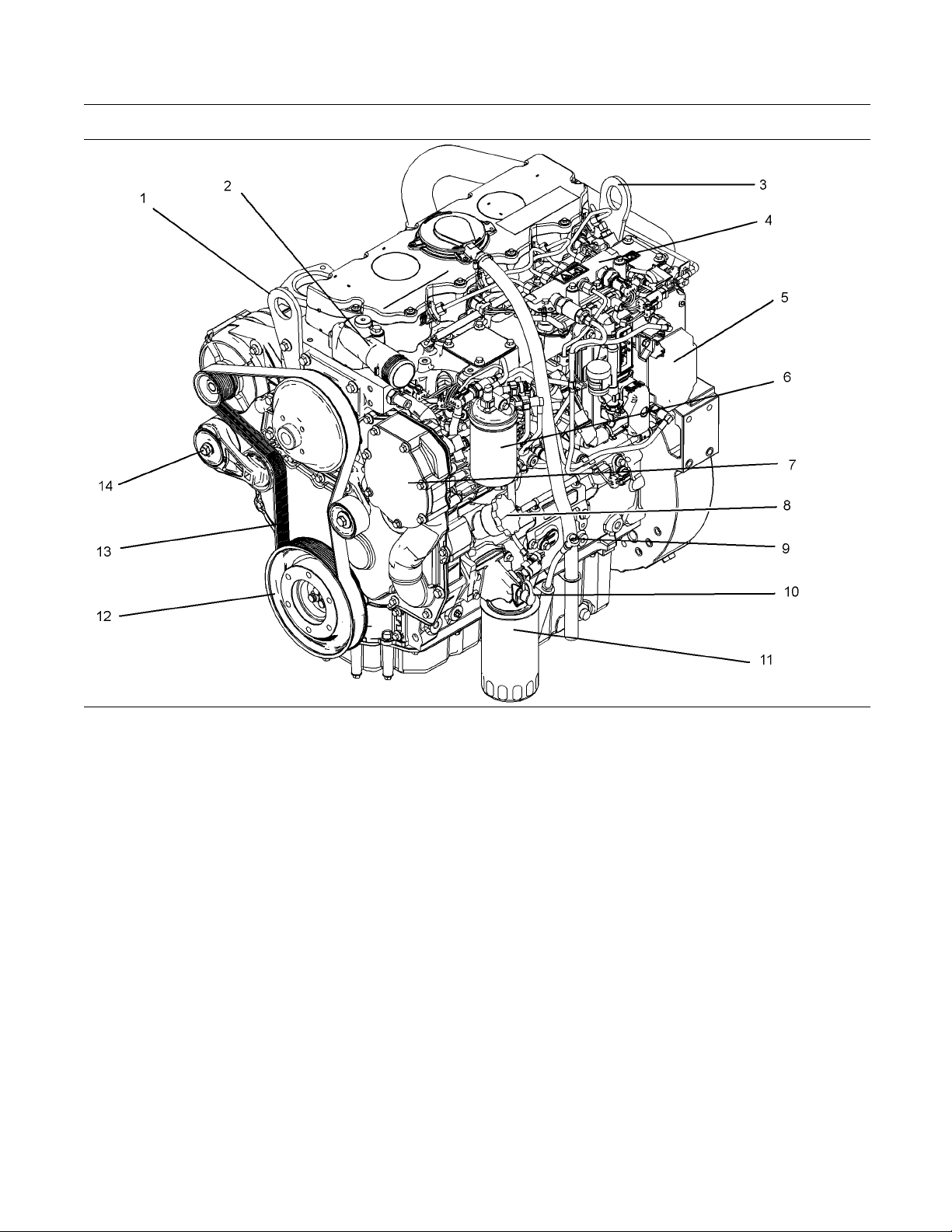
Illustration 16
The 1104D NH engine is turbocharged.
Front left engine view
(1) Front lifting eye
(2) Water outlet
(3) Rear lifting eye
(4) Fuel manifold (rail)
(5) Electronic control module
(6) Secondary fuel filter
(7) Water pump
(8) Oil Filler
(9) Oil gauge
(10) Oil sampling valve
g01428165
(11) Oil filter
(12) Crankshaft pulley
(13) Drive Belt
(14) Belt tensioner
Page 20
20 SEBU8172-02
Product Information Section
Model Views
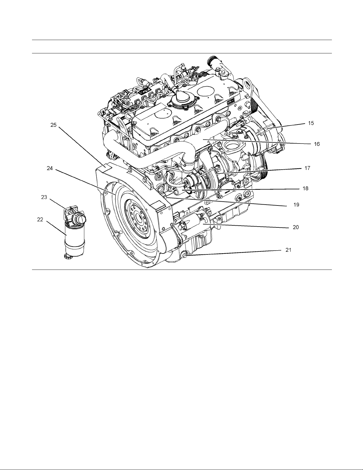
Illustration 17
Rear right engine view
(15) Alternator
(16) Exhaust manifold
(17) Turbocharger
(18) Wastegate solenoid
(19) Drain plug or coolant sampling valve
(20) Starting Motor
(21) Oil drain plug
(22) Primary fuel filter
Note: The primary fuel filter may be mounted off the
engine.
i04925801
Engine Description
The 1104 Electronic Engine models NH and NJ are
designed for the following applications: machine and
industrial mobile equipment. The engine is available
in the following type of aspiration:
Turbocharged
•
Turbocharged aftercooled
•
In-line 4 cylinder
•
g01428176
(23) Hand fuel priming pump
(24) Flywheel
(25) Flywheel housing
Engine Specifications
Note: The front end of the engine is opposite the
flywheel end of the engine. The left and the right
sides of the engine are determined from the flywheel
end. The number 1 cylinder is the front cylinder.
Emissions Control Systems
NH - Direct Diesel Injection, Turbocharger, and
Engine Control Module
NJ - Direct Diesel Injection, Turbocharger with Air to
Air Charge Cooler and Engine Control Module
Page 21
SEBU8172-02 21
Product Information Section
Model Views
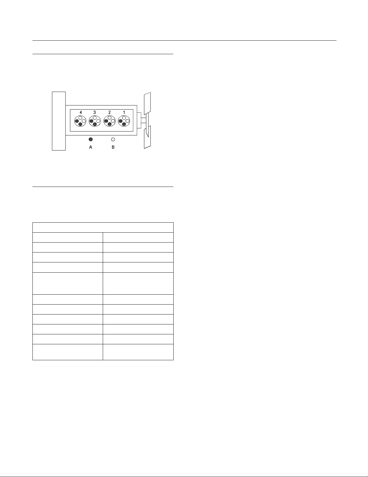
Illustration 18
(A) Exhaust valves
(B) Inlet valves
Table 1
1104 Electronic Engine Specifications
Operating Range (rpm)
Number of Cylinders
Bore
Stroke 127 mm (5.0 inch)
Aspiration NH Turbocharged engine
Compression Ratio 16.2:1
Displacement
Firing Order 1,3,4,2
Rotation (flywheel end) Counterclockwise
Valve Lash Setting (Inlet) 0.35 mm (0.013 inch)
lve Lash Setting
Va
(Exhaust)
(1)
The operating rpm is dependent on the engine rating, the
application, and the configuration of the throttle.
750 to 2640
4 In-Line
105 mm (4.13 inch)
NJ Turbocharged engine
that is aftercooled
4.4 L (269 in
0.35 mm (0.013 inch)
g01187485
(1)
3
)
Electronic Engine Features
The engine operating conditions are monitored.
The Electronic Control Module (ECM) controls the
response of the engine to these conditions and to
the demands of the operator. These conditions and
operator demands determine the precise control of
fuel injection by the ECM. The electronic engine
control system provides the following features:
Engine monitoring
•
Engine speed go
•
Control of the injection pressure
•
Cold start strategy
•
Automatic ai
•
Torque rise shaping
•
Injection timing control
•
System diag
•
verning
r/fuel ratio co ntrol
nostics
For more information on electronic engine features,
refer to th
e Operation and Maintenance Manual,
“Features and Controls” topic (Operation Section).
Engine Diagnostics
The engin
that the engine systems are functioning correctly. The
operator will be alerted to the condition by a “Stop or
Warning”
horsepower and the vehicle speed may be limited.
Theelectronicservicetoolmaybeusedtodisplay
the diag
There are three types of diagnostic codes: active,
logged,
Most of the diagnostic codes are logged and stored
in the E
the Operation and Maintenance Manual, “Engine
Diagnostics” topic (Operation Section).
The ECM provides an electronic governor that
controls the injector output in order to maintain the
desir
Engin
The cooling system consists of the following
comp
Gear-driven centrifugal water pump
•
Water temperature regulator which regulates the
•
engine coolant temperature
Gear-driven rotor type oil pump
•
Oil
•
The engine lubricating oil is supplied by a rotor type
l pump. The engine lubricating oil is cooled and the
oi
engine lubricating oil is filtered. The bypass valves
can provide unrestricted flow of lubrication oil to
e engine if the oil filter element should become
th
plugged.
e has built-in diagnostics in order to ensure
lamp. Under certain conditions, the engine
nostic codes.
and event.
CM. For additional information, refer to
ed engine rpm.
e Cooling and Lubrication
onents:
cooler
Page 22

22 SEBU8172-02
Product Information Section
Model Views
Engine efficien
engine performance depend on adherence to proper
operation and maintenance recommendations.
Engine perfor
the use of recommended fuels, lubrication oils, and
coolants. Refer to this Operation and Maintenance
Manual, “Mai
information on maintenance items.
cy, efficiency of emission controls, and
mance and efficiency also depend on
ntenance Interval Schedule” for more
Page 23
SEBU8172-02 23
Product Information Section
Product Identification Information
Product Identification
Information
Plate Locations and Film
Locations
i02378644
Perkins dealer
these numbers in order to determine the components
that were included with the engine. This permits
accurate iden
The numbers for fuel setting information for electronic
engines are s
These numbers can be read by using the Electronic
Service Tool.
s or Perkins distributors need all of
tification of replacement part numbers.
tored within the personality module.
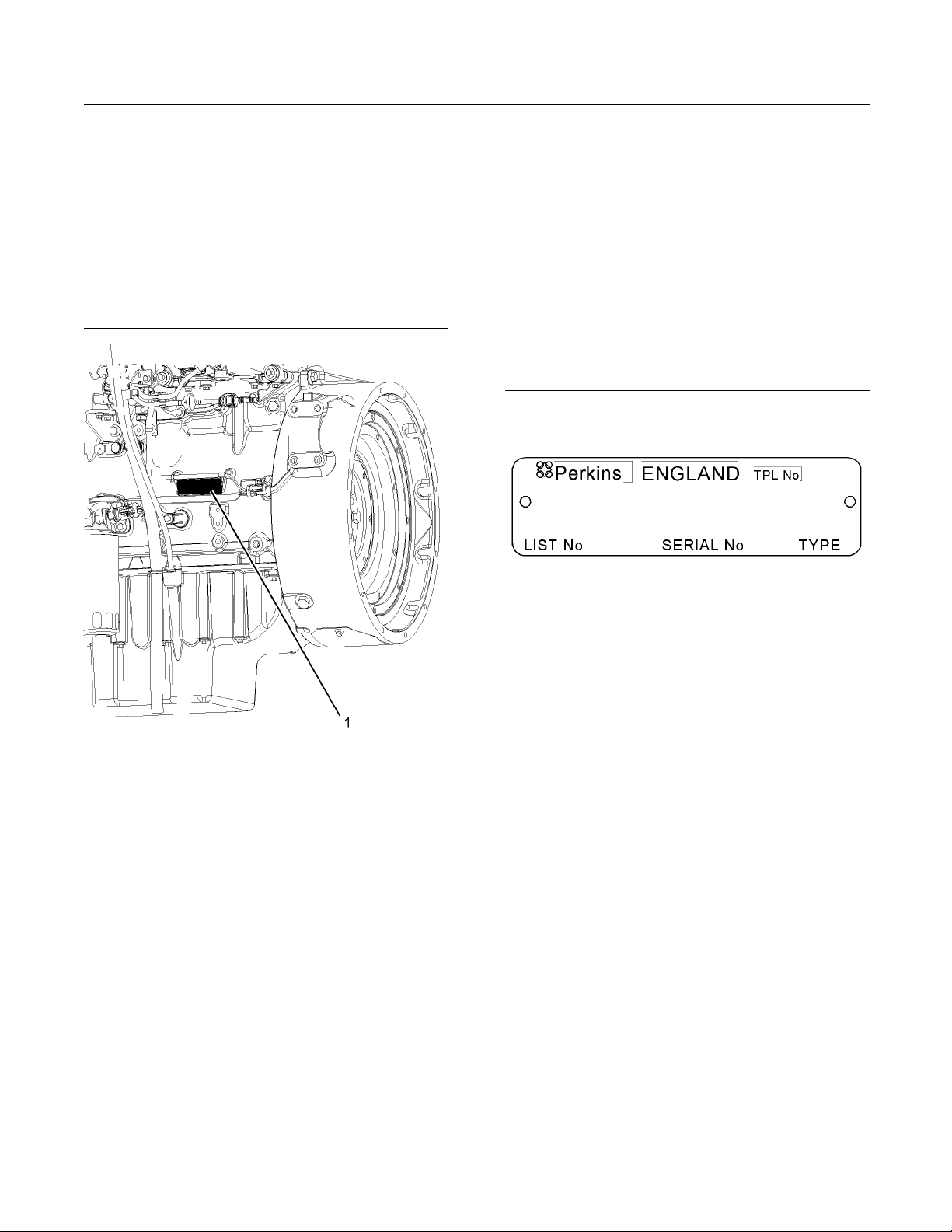
Serial Number Plate (1)
The engine serial number plate is located on the left
side of the cylinder block to the rear of the engine.
Illustration 19
Location of the serial number plate
Perkins engines are identified by an engine serial
number.
An example of an engine number is
NH*****U000001J.
*****
____________________The list number for the engine
_____________________ _____________ _______Type of engine
NH
____________________________Built in the United Kingdom
U
000001
J
___________________________Engine Serial Number
_____________________________________ Year of Manufacture
g01248563
Illustration 20
Serial number plate
g01094203
i02164876
Reference N umbers
Information for the following items may be needed to
order parts. Locate the information for your engine.
Record the information in the appropriate space.
Make a copy of this list for a record. Keep the
information for future reference.
Record for Reference
Engine Model _ ______________________________________________
Engine Serial number _____________________________________
Engine Low Idle rpm ______________________________________
Engine Full Load rpm _____________________________________
Primary Fuel Filter _________________________________________
Water Separator Element ________________________________
Secondary Fuel Filter Element __________________________
Page 24
24 SEBU8172-02
Product Information Section
Product Identification Information
Lubrication Oi
l Filter Element
___________________________
Auxiliary Oil Filter Element _______________________________
Total Lubrication System Capacity _____________________
Total Coolin
g System Capacity
_________________________
Air Cleaner Element _______________________________________
Fan Drive Belt ______________________________________________
______________________________________________
Alternator
Emissions
Belt
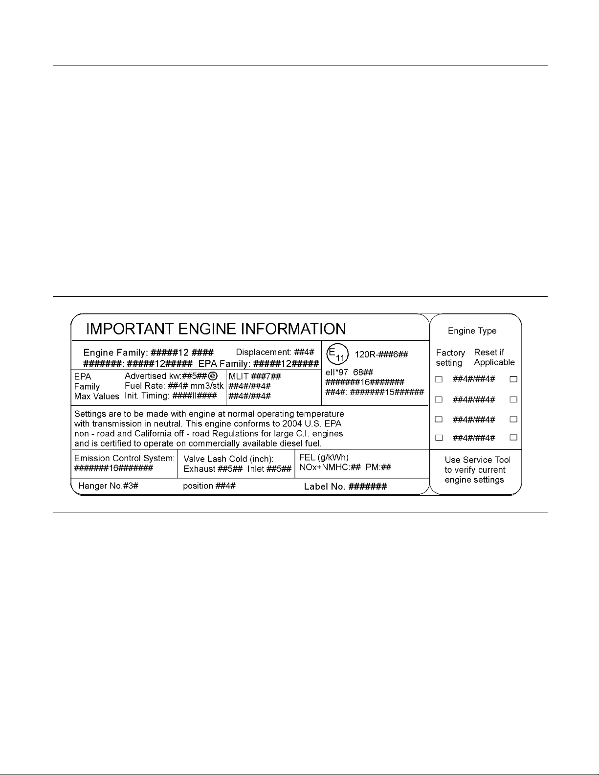
i02861254
Certification Film
Illustration 21
Typical e xample
g01440937
Page 25
SEBU8172-02 25
Operation Section
Lifting and Storage
Operation Section
Lifting and Storage
Engine Lifting
i02164186
Some removals r
obtain correct balance and safety.
To re m o ve th e e
are on the engine.
Lifting eyes
engine arrangements. Alterations to the lifting eyes
and/or the engine make the lifting eyes and the lifting
fixtures obs
that correct lifting devices are provided. Consult
your Perkins dealer or your Perkins distributor for
informatio
lifting.
n regarding fixtures for correct engine
equire lifting the fixtures in order to
ngine ONLY, use the lifting eyes that
are designed and installed for specific
olete. If alterations are made, ensure
i02308881
Engine Storage
If the engine is not started for a month or longer the
lubricating oil will drain from the cylinder walls and
from the piston rings. Rust can form on the cylinder
walls. Rust on the cylinder walls will cause increased
engine wear and a reduction in engine service life.
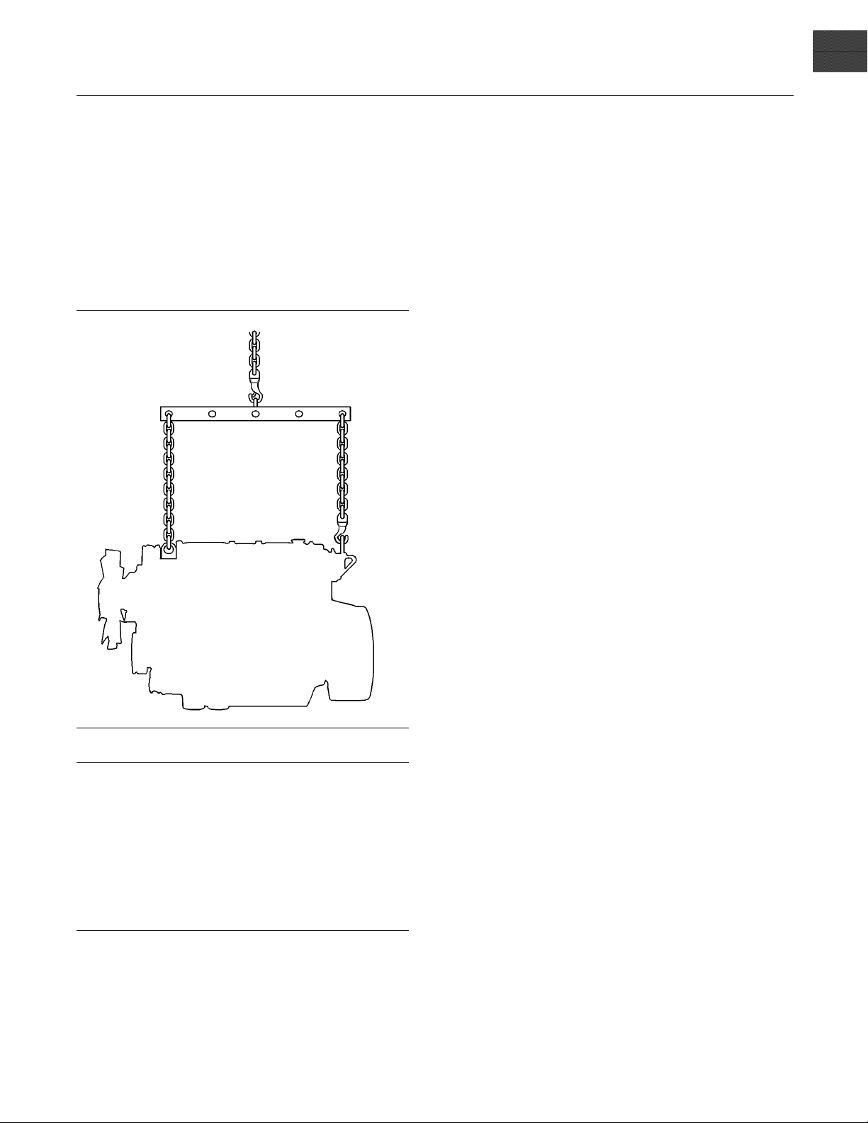
Illustration 22
NOTICE
Never bend the eyebolts and the brackets. Only load
eyebolts and the brackets under tension. Remem-
the
ber that the capacity of an eyebolt is less as the angle
between the supporting members and the object be-
es less than 90 degrees.
com
When it is necessary to remove a component at an
gle, only use a link bracket that is properly rated for
an
the weight.
se a hoist to remove heavy components. Use
U
an adjustable lifting beam to lift the engine. All
supporting members (chains and cables) should be
arallel to each other. The chains and cables should
p
be perpendicular to the top of the object that is being
lifted.
g01097527
Perkins are not responsible for damage which may
occur when an engine is in storage after a period in
service.
Your Perkins dealer or your Perkins distributor can
assist in preparing the engine for extended storage
periods.
If an engine is out of operation and if use of the
engine is not planned for more than one month, a
complete protection procedure is recommended.
To help prevent excessive engine wear and corrosion
to the engine, use the following guidelines:
1. Completely clean the outside of the engine.
2. Ensure that the vehicle is on level ground.
3. Drain the fuel system completely and refill
thesystemwithpreservativefuel.1772204
POWERPARTLay-Up1canbemixedwith
the normal fuel in order to change the fuel into
preservative fuel.
If preservative fuel is not available, the fuel system
can be filled with normal fuel. This fuel must be
discarded at the end of the storage period together
with the fuel filter elements.
Page 26
26 SEBU8172-02
Operation Section
Lifting and Storage
Personal injury can result from hot coolant. Any
contact with hot coolant or with steam c an cause
severe burns. Allow cooling system components
to cool before the cooling system is drained.
4. Drain and refill the cooling system. Refer to this
Operation and Maintenance Manual, “Cooling
System coolant (Commercial Heavy Duty Change or Cooling System coolant (ELC) Change” for information on draining, flushing and
refilling the cooling system.
Contact with high pressure fuel may cause fluid
penetration and burn hazards. High pressure fuel spray may cause a fire hazard. Failure to follow these inspection, maintenance and service instructions may cause personal injury or death.
5. Operate the engine until the engine reaches
normal operating temperature. Stop the engine.
After the engine has stopped, you must wait for 60
seconds in order to allow the fuel pressure to be
purged from the high pressure fuel lines before any
service or repair is performed on the engine fuel
lines. If necessary, perform minor adjustments.
Repair any leaks from the low pressure fuel
system and from the cooling, lubrication or air
systems. Replace any high pressure fuel line that
has leaked. Refer to Disassembly and assembly
Manual, “Fuel Injection Lines - Install”.
6. Drain the lubricating oil from the oil pan.
Renew the canister(s) of the lubricating oil filter.
9. If equipped, re
element. Seal the end of the breather pipe.
10. Remove the val
1762811 POWERPART Lay-Up 2 around the
rocker shaft assembly.
11. Remove the glow plugs. Slowly rotate the
crankshaft. By checking the valves, position the
piston at BD
Lay-Up 2 for two seconds into the cylinder bore.
This procedure must be carried out on each
cylinder.
12. Install the glow plugs. Install the valve mechanism
cover.
13. Remove the pipes that are installed between
the air filt
Spray 1762811 POWERPART Lay-Up 2 into
the turbocharger. The duration of the spray is
printed o
with waterproof tape.
14. Remove th
the turbocharger. Spray 1762811 POWERPART
Lay-Up 2 into the turbocharger. The duration of
the spra
turbocharger with waterproof tape.
15. Seal the
with waterproof tape.
16. Remove
belt into storage.
17. In o rd
of the engine, spray the engine with 1734115
POWERPART Lay-Up 3. Do not spray the area
insid
y is printed on the container. Seal the
er to prevent corrosion to the outside
e the alternator.
place the crankcase breather
ve mechanism cover. Spray
C. Spray 1762811 POWERPART
er assembly and the turbocharger.
n the container. Seal the turbocharger
e exhaust pipe from the output side of
vent of the fuel tank or the fuel filler cap
the alternator drive belt and put the drive
Fill the oil pan to the Full Mark on the engine oil
level gauge with new, clean lubricating oil. Add
1762811 POWERPARTLay-Up2totheoilin
order to protect the engine against corrosion. If
1762811 POWERPART Lay-Up 2 is not available,
use a preservative of the correct specification
instead of the lubricating oil. If a preservative is
used, this must be drained completely at the end
of the storage period and the oil pan must be
refilled to the correct level with normal lubricating
oil.
7. Operate the engine in order to circulate engine oil.
8. Disconnect the battery. Ensure that the battery is
in a fully charged condition. Protect the terminals
against corrosion. 1734115 POWERPART
Lay-Up 3 can be used on the terminals. Put the
battery into safe storage.
Page 27
SEBU8172-02 27
Operation Section
Gauges and Indicators
Gauges and Ind icators
i02861754
Gauges and Indicators
Your engine
the gauges that are described. For more information
about the gauge package, see the OEM information.
Gauges provide indications of engine performance.
Ensure that the gauges are in good working order.
Determine
the gauges over a period of time.
Noticeab
potential gauge or engine problems. Problems may
also be indicated by gauge readings that change
even if t
Determine and correct the cause of any significant
change in the readings. Consult your Perkins dealer
or your P
Some engine applications are equipped with Indicator
Lamps.
aid. There are two lamps. One lamp has an orange
lens and the other lamp has a red lens.
These indicator lamps can be used in two ways:
The in
•
current operational status of the engine. The
indicator lamps can also indicate that the engine
has a f
via the ignition switch.
The i
•
diagnostic codes. This system is activated by
pressing the Flash Code button.
Refer to the Troubleshooting Guide, “Indicator
Lamps” for further information.
If no oil pressure is indicated, STOP the engine. If
maximum coolant temperature is exceeded, STOP
the engine. Engine damage can result.
SAE10W40is350to450kPa(50to65psi)atrated
rpm.
A lower oil pressure is normal at low idle. If the load
is stable and the gauge reading changes, perform
the following procedure:
may not have the same gauges or all of
the normal operating range by observing
le changes in gauge readings indicate
he readings are within specifications.
erkins distributor for assistance.
Indicator lamps can be used as a diagnostic
dicatorlampscanbeusedtoidentifythe
ault. This system is automatically operated
ndicator lamps can be used to identify active
NOTICE
Engine Oil Pressure – Th e oil pressure
should be greatest after a cold engine is
started. The typical engine oil pressure with
1. Remove the load
2. Stop the engine.
3. Check and maintain the oil level.
Jacket Water
Typical temperature range is 83° to 95°C
(181.4° to 171°F). The maximum allowable
temperatur
system at 48 kPa (7 psi) is 103 °C (217.4 °F). Higher
temperatures may occur under certain conditions.
The water te
to load. The temperature reading should never
exceed 7 °C (44.6 °F) below the boiling point for the
pressuriz
A 100 kPa (14.5 psi) radiator cap may be installed on
the cooling system. The temperature of this cooling
system mus
If the engine is operating above the normal range
and steam
procedure:
1. Reduce t
2. Determine if the engine must be shut down
immedia
reducing the load.
3. Inspec
load, the engine is running at high idle. The engine is
runni
lever is at the full throttle position with maximum
rated load.
To help prevent engine damage, never exceed the
high idle rpm. Overspeeding can result in serious
damage to the engine. Operation at speeds exceeding high idle rpm should be kept to a minimum.
indicator should be to the “+” side of “0” (zero).
is in the “on” position.
e at sea level with the pressurized cooling
mperature reading may vary according
ed system that is being used.
t not exceed 112 °C (233.6 °F).
becomes apparent, perform the following
he load and the engine rpm.
tely or if the engine can be cooled by
t the cooling system for leaks.
Tachometer – This gauge indicates engine
speed (
ismovedtothefullthrottlepositionwithout
ng at the full load rpm when the throttle control
Ammeter – This gauge indicates the
amount of charge or discharge in the
battery charging circuit. Operation of the
Fuel Level – This gauge indicates the fuel
level in the fuel tank. The fuel level gauge
operates when the “START/STOP” switch
.
Coolant Temperature –
rpm). When the throttle control lever
NOTICE
Page 28

28 SEBU8172-02
Operation Section
Gauges and Indicators
Service Hour Meter – The gauge indicates
total operating hours of the engine.
Page 29
SEBU8172-02 29
Operation Section
Features and Controls
Features and Controls
i02651062
Monitoring System
If the Shutdown mode has been selected and the
warning in
take as little as 20 seconds from the time the warning indicator is activated. Depending on the application
avoid personal injury. The engine can be restarted
following shutdown for emergency maneuvers, if
necessar
The Engine Monitoring System is not a guarantee
against catastrophic failures. Programmed delays
and derate schedules are designed to minimize false
alarms and provide time for the operator to stop the
engine.
The following parameters are monitored:
Coolant temperature
•
Intake air temperature
•
Engine intake manifold pressure
•
Engine Oil pressure
•
Pressure in the fuel rail
•
dicator activates, engine shutdown may
, special precautions should be taken to
y.
NOTICE
“Warning”
The “Warning” lamp and the warning signal (orange
lamp) turn “ON
continuously in order to alert the operator that one or
more of the engine parameters is not within normal
operating ra
” and the warning signal is activated
nge.
“Warning/Derate”
The “Diagnostic” lamp turns “ON” and the warning
signal (red lamp) is activated. After the warning, the
engine powe
begin to flash when the derating occurs.
The engine
preset operational limits. The engine derate is
achieved by restricting the amount of fuel that is
available
reduction of fuel is dependent on the severity of the
fault that has caused the engine derate, typically up
to a limit
predetermined reduction in engine power.
“Warnin
The “Diagnostic” lamp turns “ON” and the warning
signal (
the engine power will be derated. The engine will
continue at the rpm of the set derate until a shutdown
of the e
after a shutdown for use in an emergency.
Ashutd
as 20 seconds. The engine can be restarted after
a shutdown for use in an emergency. However,
the ca
Theenginemayshutdownagaininaslittleas20
seconds.
r will be derated. The warning lamp will
will be derated if the engine exceeds
for each injection. The amount of this
of 50%. This reduction in fuel results in a
g/Derate/Shutdown”
red lamp) is activated. After the warning,
ngine occurs. The engine can be restarted
own of the engine may occur in as little
use of the initial shutdown may still exist.
Engine speed/timing
•
Programmable O ptions and
Systems Operation
If the Warning/Derate/Shutdown mode has been
selected and the warning indicator activates,
bring the engine to a stop whenever possible. Depending on the application, special precautions
should be taken to avoid personal injury.
The engine can be programmed to the following
modes:
If there is a signal for low oil pressure or for coolant
temperature, there will be a two second delay in
r to verify the condition.
orde
For each of the programmed modes, refer to
bleshooting , “Indicator Lamps” for more
Trou
information on Indicator Lamps.
more information or assistance for repairs, consult
For
your Perkins dealer or your Perkins distributor.
Page 30

30 SEBU8172-02
Operation Section
Features and Controls
i02296746
Monitoring System
Table 2
Warning
Lamp
ON ON
OFF OFF
ON OFF
ON FLASHING
FLASHING OFF
FLASHING FLASHING
ON ON
Shutdown
Lamp
Lamp Status Description of lamp status Engine Status
Lamp check When the engine start switch is turned to the
“ON” position both lamps will illuminate for 2
seconds only.
No faults There are no active diagnostic faults.
Active
diagnostic
fault
Active
diagnostic
fault
Warning One or more of the engine protection values
Derate and
warning
Engine
shutdown
An active diagnostic fault has been detected.
A serious active diagnostic fault has been
detected and an engine derate has been
invoked.
has been exceeded.
One or more of the engine protection values
has been exceeded.
One or more of the engine protection values has
been exceeded or a serious active diagnostic
as been detected.
fault h
The engine has not been
started.
Theengineisrunning
normally.
Theengineisrunning
normally.
Theengineisrunning
but the engine has been
derated.
Theengineisrunning
normally.
Theengineisrunning
but the engine has been
derated.
The engine is shutdown or
shutdown is imminent.
i02861773
Sensors and Electrical
Components
Sensor Locations
ustration 23 shows the typical locations of the
Ill
sensors and the ECM on the engine. Specificengines
may appear different from the illustration due to
ferences in applications.
dif
Page 31

SEBU8172-02 31
Operation Section
Features and Controls
Illustration 23
(1) Coolant temperature sensor
(2) Intake manifold pressure sensor
(3) Inlet air temperature sensor
(4) Fuel pressure sensor
(5) Electronic control m odule
(6) Primary position sensor
Illustration 24 shows the sensors and the ECM in
position on the engine.
g01425443
(7) Secondary position sensor
(8) Engine oil pressure sensor
Page 32

32 SEBU8172-02
Operation Section
Features and Controls
Illustration 24
Failure of Sensors
All Sensors
A failure of any of the sensors may be caused by one
of the following malfunctions:
Sensor output is open.
•
Sensor output is shorted to “- battery” or “+ battery”.
•
Measured reading of the sensor is out of the
•
specification.
g01425468
Programmable Monitoring System
(PMS)
The Programmable Monitoring System determines
the level of action that is taken by the Electronic
Control Module (ECM) in response to a condition
that can damage the engine. These conditions are
identified by the ECM from the signals that are
produced from the following sensors.
Coolant Temperature Sensor
•
Intake manifold Air Temperature Sensor
•
Intake manifold Pressure Sensor
•
Fuel Pressure Sensor
•
Page 33

SEBU8172-02 33
Operation Section
Features and Controls
Engine Oil Pres
•
Primary Speed/Timing Sensor
•
Secondary Speed/Timing Sensor
•
sure Sensor
Coolant Temperature Sensor 1
The coolant t
coolant temperature. The output of the ECM (5) can
indicate a high coolant temperature through a relay
or a lamp. Th
by the ECM to determine initiation of the Cold Start
Condition.
Failure of the Coolant Temperature
Sensor
The ECM (5) will detect a failure of the coolant
temperature sensor. The diagnostic lamp will warn the
operator
sensor. A failure of the coolant temperature sensor
will not cause a shutdown of the engine or any
horsepow
operation of the sensor, refer to Troubleshooting,
“Engine Temperature Sensor Circuit - Test”.
emperature sensor monitors engine
e coolant temperature sensor is used
about the status of the coolant temperature
er change. In order to check the correct
Electronic Control Module 5
The ECM is the control computer of the engine. The
ECM provides power to the electronics. The ECM
monitors data that is input from the sensors of the
engine. The ECM acts as a governor in order to
control the speed and the power of the engine.
The ECM adjusts injection timing and fuel pressure
for the best engine performance, the best fuel
economy and the best control of exhaust emissions.
Primary Speed/Timing Sensor 6
If the ECM (5) does not receive a signal from the
primary speed/timing sensor , the “DIAGNOSTIC”
lamp will indicate a diagnostic fault code which will be
logged in the ECM memory.
If the ECM does not receive a signal from the primary
speed/timing sensor (7), the ECM will read the signal
from the secondary speed/timing sensor (8). The
ECM continually checks in order to determine if there
is a signal from both sensors.
Intermittent failure of the sensors will cause erratic
engine control.
Intake Manifold Air Temperature
Sensor 2
Note: T
The location will depend on the type of engine.
The in
the intake air temperature. A signal is sent to the
ECM (5). The intake manifold air temperature sensor
is als
Cold Start Strategy.
In ord
refer to Troubleshooting, “EngineTemperature Sensor
Circuit - Test”.
his sensor can have two different locations.
take manifold air temperature sensor measures
o used by the ECM to determine initiation of the
er to check the correct operation of the sensor,
Intake Man ifold Pressure Sensor 3
The intake manifold pressure sensor measures
pressure in the manifold. A signal is sent to the ECM
.
(5)
l Pressure Sensor 4
Fue
The fuel pressure sensor measures the fuel pressure
the fuel manifold. A signal is sent to the ECM (5).
in
Failure of the Primary Speed/Timing
Sensor
Correct operation of the primary speed/timing
sensor is essential. Software in the ECM protects
against reverse running of the engine. If the primary
speed/timing sensor fails there is no automatic
protection against reverse running. In some
applications, it is possible for the transmission to
run the engine in reverse. In this event, Stop the
engineimmediately.Turnthekeyswitchtothe“OFF”
position.
In order to check the correct operation of the sensor,
refer to Troubleshooting, “Engine speed/Timing
sensor - Test”.
Secondary Speed/Timing Sensor 7
The signal from the secondary speed/timing sensor
is used by the ECM (5) on engine start-up in order
to check the stroke of the pistons. The secondary
speed/timing sensor may be used by the ECM
in order to operate the engine if the primary
speed/timing sensor is faulty.
In order to check the correct operation of the sensor,
refer to Troubleshooting, “Engine speed/Timing
sensor-Test”.
Page 34

34 SEBU8172-02
Operation Section
Features and Controls
Engine Oil Pressure Sensor 8
Note: This sensor can have two different locations.
The location will depend on the type of engine.
The engine oil pressure sensor is an absolute
pressure sensor that measures the engine oil
pressure in the main oil gallery. The engine oil
pressure sensor detects engine oil pressure for
diagnostic purposes. The engine oil pressure sensor
sends a signal to the ECM (5).
Low Oil Pressure Warning
The setpoint for the low pressure warning is
dependent upon the engine speed. The fault will be
active and logged only if the engine has been running
for more than 8 seconds.
Very Low Oil Pressure Warning
The very low oil pressure setpoint is dependent
upon the engine speed. If the DERATE mode of the
engine monitoring system is selected, the ECM (5)
will derate the engine power. The engine horsepower
will be limited.
Operating leve
•
Operating rpm
•
The particular shutoff may need to be reset before
theenginewillstart.
Always determine the cause of the engine shutdown.
Make necessary repairs before attempting to restart
the engine.
Be familiar with the following items:
Types and locations of shutoff
•
Condition
•
The resetting procedure that is required to restart
•
the engin
l
NOTICE
s which cause each shutoff to function
e
Alarms
The alarms are electrically operated. The operation
of the al
arms are controlled by the ECM.
Failure of the Engine Oil Pressure Sensor
The ECM (5) will detect failure of the engine oil
pressure sensor. The diagnostic lamp warns the user
about the status of the engine oil pressure sensor.
The engine oil pressure related strategies will be
disabled in the event of a failure of the engine oil
pressure sensor. A failure of the engine oil pressure
sensor will not cause a shutdown of the engine or
any horsepower change. In order to check the correct
operation of the sensor, refer to Troubleshooting, “5
Volt Sensor Supply Circuit - Test”.
58345
i028
Engine Shutoffs and Engine
rms
Ala
Shutoffs
The shutoffs are electrically operated or mechanically
operated. The electrically operated shutoffs are
ntrolled by the ECM.
co
The alarm is operated by a sensor or by a switch.
When th
is sent to the ECM. An event code is created by
the ECM. The ECM will send a signal in order to
illumi
Your engine may be equipped with the following
senso
Coolant level – The low coolant level switch
indic
Coolant temperature – The coolant temperature
sens
temperature.
Inta
manifold air temperature sensor indicates high intake
air temperature.
Intake manifold pressure – The intake manifold
pressure sensor checks the rated pressure in the
eng
Fuel rail pressure – The fuel rail pressure sensor
ch
rail.
e sensor or the switch is activated a signal
nate the lamp.
rs or switches:
ates when the coolant level is low.
or indicates high jacket water coolant
ke manifold air temperature – The intake
ine manifold.
ecks for high pressure or low pressure in the fuel
Shutoffs are set at critical levels for the following
tems:
i
Operating temperature
•
Operating pressure
•
gine oil pressure – The engine oil pressure
En
sensor indicates when oil pressure drops below rated
system pressure, at a set engine speed.
Page 35

SEBU8172-02 35
Operation Section
Features and Controls
Engine overspe
sensor checks the engine speed. The alarm is
activated at 3000 RPM.
Air filter restriction – The switch checks the air
filter when the engine is operating.
User defined switch – This switch can shut down
the engine remotely.
Water in fuel switch – This switch checks for water
in the primary fuel filter when the engine is operating.
Note: The sensing element of the coolant
temperature switch must be submerged in coolant
in order to
Engines may be equipped with alarms in order
to alert th
conditions occur.
When an alarm is activated, corrective measures must
be taken
in order to avoid possible engine damage.
e operator when undesirable operating
before the situation becomes an emergency
ed – The primary speed/timing
operate.
NOTICE
If corre
reasonable time, engine damage could result. The
alarm will continue until the condition is corrected.
The ala
Testin
Turning the keyswitch to the ON position will check
the in
indicator lights will be illuminated for two seconds
after the keyswitch is operated. Replace suspect
bulb
Refer to Troubleshooting for more information.
ctive measures are not taken within a
rmmayneedtobereset.
g
dicator lights on the control panel. All the
s immediately.
i02237393
Overspeed
An overspeed condition is detected by the Electronic
Control Module (ECM). The event code will be
logged if the engine speed exceeds 3000 rpm. The
“DIAGNOSTIC” lamp will indicate a diagnostic active
code. The diagnostic active code will remain active
until the engine speed drops to 2800 rpm.
Page 36

36 SEBU8172-02
Operation Section
Engine Diagnostics
Engine Diagnostics
i02651093
Self-Diagnostics
Perkins electronic engines have the capability to
perform a self-diagnostics test. When the system
detects an active problem, a diagnostic lamp
is activated. Diagnostic codes will be stored in
permanent memory in the Electronic Control Module
(ECM). The diagnostic codes can be retrieved
by using the electronic service tool. Refer to
Troubleshooting , “Electronic Service Tools” for
further information.
Some installations have electronic displays that
provide direct readouts of the engine diagnostic
codes. Refer to the manual that is provided
by the OEM for more information on retrieving
engine diagnostic codes. Alternatively refer to
Troubleshooting , “Indicator Lamps” for further
information.
Active codes represent problems that currently exist.
These problems should be investigated first.
Logged codes represent the following items:
Intermittent problems
•
Recorded events
•
Performance history
•
The problems may have been repaired since the
logging of the code. These codes do not indicate that
a repair is needed. The codes are guides or signals
when a situation exists. Codes may be helpful to
troubleshoot problems.
When the problems have been corrected, the
corresponding logged fault codes should be cleared.
i02651107
Diagnostic Lamp
A diagnostic lamp is used to indicate the existence of
active fault. Refer to Troubleshooting , “Indicator
an
Lamps” for more information. A fault diagnostic
code will remain active until the problem is repaired.
he diagnostic code may be retrieved by using the
T
electronic service tool. Refer to Troubleshooting ,
“Electronic Service Tools” for more information.
i02855276
Diagnostic Flash Code
Retrieval
“Diagnostic” Lamp
Use the “DIAGNOSTIC” Lamp or an electronic
service tool to determine the diagnostic flash code.
Usethefollowingproceduretoretrievetheflash
codes if the engine is equipped with a “DIAGNOSTIC”
lamp:
1. Turn the keyswitch “ON/OFF” two times within 3
seconds.
A flashing“YELLOW” lamp indicates a 3 digit code for
the engin
system diagnostic message. Count the first sequence
of flashes in order to determine the first digit of the
flash code
sequence of flashes will identify the second digit of
the flash code. After the second pause, the third
sequenc
Any additional flash codes will follow after a pause.
These co
Flash Code 551 indicates that No Detected Faults
have occurred since the ignition keyswitch has been
turned
For further information, assistance for repairs, or
troub
consult an authorized Perkins dealer.
Table
a brief description of the flash codes.
Note
performance with “ACTIVE” flash codes.
Some
may also indicate that a mechanical system needs
attention. Troubleshooting is not required for code
“55
codes will limit the operation or the performance of
the engine.
Table 3 indicates the potential effect on the engine
performance with active flash codes. Table 3 also
rms a list of Electronic diagnostic codes and
fo
descriptions.
e. The sequence of flashes represents the
. After a two second pause, the second
eofflashes will identify the flash code.
des will be displayed in the same manner.
to the ON position.
leshooting, refer to the Service Manual or
3 lists the flash codes and the table also gives
: Table 3indicates the potential effect on engine
codes record events. Also, some codes
1”. Code 001 will not display a flash code. Some
Page 37

SEBU8172-02 37
Operation Section
Engine Diagnostics
Table 3
Flash Codes for the Industrial Engine
Effect On Engine Performance
Diagnostic Flash Code
Engine
Misfire
Low
Power
Reduced
Engine
Speed
111 Cylinder 1 Fault X X X
112 Cylinder 2 Fault X X X
113 Cylinder 3 Fault X X X
114 Cylinder 4 Fault X X X
Intake Ma
133
Temperature sensor
fault
Primary Speed/
141
Timing Sensor Fault
nifold
XX
(5)
XX
Secondary
142
Speed/Timing
Sensor Fault
Timing Calibration
143
Fault
X X
Engine Operation
144
Mode Selector
Switc
High Air Filter
151
Restriction
Thro
154
sensor Fault
hFault
ttle Position
XX
XX
XX
Secondary Throttle
155
Position sensor
XX
Fault
Oil Pressure Sensor
157
Fault
Fuel Rail Pressure
159
Sensor Fault
High Pressure Fuel
162
(5)
Pump Fault
XX X X X
XX
XX X
Coolant
168
Temperature Sensor
XX X
Fault
169 Low Engine Coolant X X
Wastegate Solenoid
177
185
Fault
High Exhaust
Temperature
XX
X
Intake Manifold
197
Pressure Sensor
XX
Fault
Glow Plug Start
199
Relay Fault
(1)
Engine
Shutdown
Suggested Operator Action
Shut
Down the
Engine
Service
(2)
(3)
X
X
Schedule a
Service.
(4)
(continued)
Page 38

38 SEBU8172-02
Operation Section
Engine Diagnostics
(Table 3, contd)
Flash Codes for the Industrial Engine
Effect On Engine Performance
Diagnostic Flash Code
Incorrect Engine
415
Software
Machine Sec
426
System Module
(6)
Fault
429 Keyswitch
Intermittent Battery
511
Power to ECM
SAE J1939 Data
514
Link Fault
urity
Fault
Engine
Misfire
Low
Power
XX X X
Reduced
Engine
Speed
XX X
XX
5VoltSensorDC
516
Power Supply
Fault
8VoltSensorDC
517
Power Supply Fault
(5)
XX
XX
Check Customer
Parameters or
527
(1)
An “X” indicates that the effect on engine performance may occur if the code is active.
(2)
Shut Down the Engine: Operate the engine c autiously. Get im mediate service. Severe engine damage ma y result.
(3)
The o
(4)
Schedule Service: T he problem should be investigated when the operator has access to a qualified service program.
(5)
These Flash Codes may affect the system under s pecific environmental conditions s uch a s engine start-up at cold temperature and
cold weather operation at high altitudes.
(6)
The e
m Parameters
Syste
(5)
perator should go to the nearest location that has a qualified se rvice program .
ngine will not start.
XX X
(1)
Engine
Shutdown
Suggested Operator Action
Shut
Down the
Engine
Service
(2)
(3)
X
Schedule a
Service.
(4)
X
i01902949
lt Logging
Fau
The system provides the capability of Fault Logging.
When the Electronic Control Module (ECM)
nerates an active diagnostic code, the code will
ge
be logged in the memory of the ECM. The codes
that have been logged by the ECM can be identified
the electronic service tool. The active codes that
by
have been logged will be cleared when the fault
has been rectified or the fault is no longer active.
he following logged faults can not be cleared from
T
the memory of the ECM without using a factory
password: Overspeed, low engine oil pressure, and
igh engine coolant temperature.
h
Page 39

SEBU8172-02 39
Operation Section
Engine Diagnostics
i02651197
Engine Operation with Active
Diagnostic Co
If a diagnostic lamp illuminates during normal engine
operation, the system has identified a situation that is
not within t
tool to check the active diagnostic codes.
he specification. Use the electronic service
des
The active d
The cause of the problem should be corrected as
soon as possible. If the cause of the active diagnostic
code is rep
diagnostic code, the diagnostic lamp will turn off.
Operation
engine can be limited as a result of the active
diagnostic code that is generated. Acceleration rates
may be sig
be automatically reduced. Refer to Troubleshooting
, “Troubleshooting with a Diagnostic Code” for more
informa
diagnostic code and the possible effect on engine
performance.
iagnostic code should be investigated.
aired and there is only one active
of the engine and performance of the
nificantly slower and power outputs may
tion on the relationship between each active
i01902995
Engine O peration with
Intermittent Diagnostic Codes
agnostic lamp illuminates during normal engine
If a di
operation and the diagnostic lamp shuts off, an
intermittent fault may have occurred. If a fault has
rred, the fault will be logged into the memory of
occu
the Electronic Control Module (ECM).
st cases, it is not necessary to stop the engine
In mo
because of an intermittent code. However, the
operator should retrieve the logged fault codes
the operator should reference the appropriate
and
information in order to identify the nature of the event.
The operator should log any observation that could
e caused the lamp to light.
hav
Low power
•
Limits of the engine speed
•
cessive smoke, etc
Ex
•
This information can be useful to help troubleshoot
he situation. The information can also be used for
t
future reference. For more information on diagnostic
codes, refer to the Troubleshooting Guide for this
ngine.
e
Page 40

40 SEBU8172-02
Operation Section
Engine Starting
Engine Starting
i02322201
Before Starting Engine
Before the e
daily maintenance and any other periodic
maintenance that is due. Refer to the Operation
and Mainte
Schedule” for more information.
Open the fu
•
All valves in the fuel return line must be open before
and durin
pressure. High fuel pressure may cause filter housing
failure or other damage.
If the engine has not been started for several weeks,
fuel may have drained from the fuel system. Air
may hav
filters have been changed, some air pockets will be
trapped in the engine. In these instances, prime the
fuel sy
Manual, “Fuel System - Prime” for more information
on priming the fuel system.
ngine is started, perform the required
nance Manual, “Maintenance Interval
el supply valve (if equipped).
NOTICE
g engine operation to help prevent high fuel
e entered the filter housing. Also, when fuel
stem. Refer to the Operation and Maintenance
i02322203
Starting the Engine
Note: Do not ad
start-up. The electronic control module (ECM) will
control the engine speed during start-up.
Starting the Engine
1. Disengage any equipment that is driven by the
engine.
2. Turn the keyswitch to the RUN position. Leave the
keyswitchintheRUNpositionuntilthewarning
light for t
3. When the warning light for the glow plugs is
extingui
position in order to engage the electric starting
motor and crank the engine.
Note: The operating period of the warning light for
the glow plugs will change due to the temperature
of the en
Do not engage the starting motor when flywheel is
turnin
gine.
g. Do not start the engine under load.
justtheenginespeedcontrolduring
he glow plugs is extinguished.
shed turn the keyswitch to the START
NOTICE
ne exhaust contains products of combustion
Engi
which may be harmful to your health. Always start
and operate the engine in a well ventilated area
if in an enclosed area, vent the exhaust to the
and,
outside.
ot start the engine or move any of the controls
Do n
•
if there is a “DO NOT OPERATE” warning tag or
similar warning tag attached to the start switch or
the controls.
to
Reset all of the shutoffs or alarm components (if
•
uipped).
eq
Ensure that any equipment that is driven by the
•
ngine has been disengaged from the engine.
e
Minimize electrical loads or remove any electrical
loads.
If the engine fails to start within 30 seconds, release
the sta
allow the starting motor to cool before attempting to
start the engine again.
4. Allow the keyswitch to return to the RUN position
5. Repeat step 2 through step 4 if the engine fails
rter switch or button and wait two minutes to
after the engine starts.
to start.
i02
325155
Cold Weather Starting
Do not use aerosol types of starting aids such as
ether. Such use could result in an explosion and
personal injury.
Startability will be improved at temperatures below
−18 °C (0 °F) from the use of a jacket water heater
or extra battery capacity.
Page 41

SEBU8172-02 41
Operation Section
Engine Starting
When Group 2 die
provide a means of minimizing starting problems
and fuel problems in cold weather: Engine oil pan
heaters, jack
line insulation.
Use the proce
starting.
Note: Do not
start-up. The electronic control module (ECM) will
control the engine speed during start-up.
1. Disengage any driven equipment.
2. Turn the ke
keyswitch in the RUN position until the warning
light for the glow plugs is extinguished.
Do not engage the starting motor when flywheel is
turning. Do not start the engine under load.
If the engine fails to start within 30 seconds, release
the starter switch or button and wait two minutes to
allow th
start the engine again.
e starting motor to cool before attempting to
sel fuel is used, the following items
et water heaters, fuel heaters, and fuel
dure that follows for cold weather
adjust the engine speed control during
yswitch to the RUN position. Leave the
NOTICE
i02322204
Starting with Jump Start
Cables
Improper jump start cable connections can cause
an explosion resulting in personal injury.
Prevent sparks near the batteries. Sparks could
cause vapors to explode. Do not allow jump start
cable ends to contact each other or the e ngine.
Note: If it is possible, first diagnose the reason for
the starting failure. Refer to Troubleshooting, “Engine
Will Not Crank and Engine Cranks But Will Not Start”
for further information. Make any necessary repairs.
If the engine will not start only due to the condition
of the battery, either charge the battery, or start the
engine by using another battery with jump start
cables.
The condition of the battery can be rechecked after
the engine has been switched OFF.
3. When th
extinguished turn the keyswitch to the START
position in order to engage the electric starting
motor a
Note: The operating period of the warning light for
the gl
of the engine.
4. Allo
after the engine starts.
5. Repe
to start.
Note
speed up the warm up process.
6. All
allow the engine to idle until the water temperature
indicator begins to rise. When idling after the
en
engine rpm from 1000 to 1200 rpm. This will
warm up the engine more quickly. Maintaining
an
will be easier with the installation of a hand
throttle. Allow the white smoke to disperse before
pr
e warning light for the glow plugs is
nd crank the engine.
ow plugs will change due to the temperature
w the keyswitch to return to the RUN position
at step 2 through step 4 if the engine fails
: The engine should not be “raced” in order to
ow the engine to idle for three to five minutes, or
gine has started in cold weather, increase the
elevated low idle speed for extended periods
oceeding with normal operation.
NOTICE
Using a battery source with the same voltage as the
ic starting motor. Use ONLY equal voltage for
electr
jump starting. The use of higher voltage will damage
the electrical system.
Do not reverse the battery cables. The alternator can
be damaged. Attach ground cable last and remove
first.
Turn all electrical accessories OFF before attaching
ump start cables.
the j
Ensure that the main power switch is in the OFF posi-
before attaching the jump start cables to the en-
tion
gine being started.
n the start switch on the stalled engine to the
1. Tur
OFF position. Turn off all the engine's accessories.
2. Con
nect one positive end of the jump start cable
to the positive cable terminal of the discharged
battery. Connect the other positive end of the jump
art cable to the positive cable terminal of the
st
electrical source.
7. Operate the engine at low load until all systems
each operating temperature. Check the gauges
r
during the warm-up period.
Page 42

42 SEBU8172-02
Operation Section
Engine Starting
3. Connect one neg
to the negative cable terminal of the electrical
source. Connect the other negative end of the
jump start cab
chassis ground. This procedure helps to prevent
potential sparks from igniting the combustible
gases that ar
4. Start the engine.
5. Immediately after the engine is started, disconnect
the jump start cables in reverse order.
After jump starting, the alternator may not be able to
fully recharge batteries that are severely discharged.
The batter
proper voltage with a battery charger after the engine
is stopped. Many batteries which are considered
unusable a
and Maintenance Manual, “Battery - Replace” and
Testing and Adjusting Manual, “Battery - Test”.
ies must be replaced or charged to the
re still rechargeable. Refer to Operation
ative end of the jump start cable
le to the engine block or to the
e produced by some batteries.
i02330138
After Starting Engine
Note: In ambient temperatures from 0 to 60°C
(32 to 140°F), the warm-up time is approximately
three minutes. In temperatures below 0°C (32°F),
additional warm-up time may be required.
When the engine idles during warm-up, observe the
following conditions:
Do not check the high pressure fuel lines with the
engine or the starting motor in operation. If you
inspect the engine in operation, always use the
proper inspection procedure in order to avoid a
fluid penetration hazard. Refer to Operation and
Maintenance Manual, “General hazard Information”.
Check for any fluid or for any air leaks at idle rpm
•
and at one-half full rpm (no load on the engine)
before operating the engine under load. This is not
possible in some applications.
Allow the engine to idle for three to five minutes, or
•
allow the engine to idle until the water temperature
indicator begins to rise. Check all gauges during
the warm-up period.
Note: Gauge readings should be observed and
the data should be recorded frequently while the
engine is operating. Comparing the data over time
will help to determine normal readings for each
gauge.Comparingdataovertimewillalsohelp
detect abnormal operating developments. Significant
changes in the readings should be investigated.
Page 43

SEBU8172-02 43
Operation Section
Engine Operation
Engine Operation
i02330143
Engine Operation
Correct ope
in obtaining the maximum life and economy of
the engine. If the directions in the Operation and
Maintenan
minimized and engine service life can be maximized.
The engine
engine reaches operating temperature. The engine
will reach normal operating temperature if the engine
is operat
light load. This procedure is more effective than idling
the engine at no load. The engine should reach
operati
Gauge readings should be observed and the data
should b
is operating. Comparing the data over time will
help to determine normal readings for each gauge.
Compar
abnormal operating developments. Significant
changes in the readings should be investigated.
ration and maintenance are key factors
ce Manual are followed, costs can be
can be operated at the rated rpm after the
ed at low idle speed and operated with a
ng temperature in a few minutes.
e recorded frequently while the engine
ingdataovertimewillalsohelpdetect
i02330149
Fuel Conservation Practices
The efficiency
economy. Perkins design and technology in
manufacturing provides maximum fuel efficiency in
all applicat
in order to attain optimum performance for the life
of the engine.
Avoid spilling fuel.
•
Fuel expan
may overflow from the fuel tank. Inspect fuel lines for
leaks. Repair the fuel lines, as needed.
Be aware of the properties of the different fuels.
•
Use only the recommended fuels.
Avoid unnecessary idling.
•
Shut off t
time.
Observe
•
Keep the air cleaner elements clean.
Maintai
•
of the engine can affect the fuel
ions. Follow the recommended procedures
ds when the fuel is warmed up. The fuel
he engine rather than idle for long periods of
the air cleaner service indicator frequently.
n the electrical systems.
One damaged battery cell will overwork the alternator.
This wi
•
•
•
•
ll consume excess power and excess fuel.
Ensure that the drive belts are correctly adjusted.
ive belts should be in good condition.
The dr
Ensure that all of the connections of the hoses are
. The connections should not leak.
tight
Ensure that the driven equipment is in good
ing order.
work
Cold engines consume excess fuel. Utilize heat
the jacket water system and the exhaust
from
system, when possible. Keep cooling system
components clean and keep cooling system
ponents in good repair. Never operate the
com
engine without water temperature regulators.
All of these items will help maintain operating
peratures.
tem
Page 44

44 SEBU8172-02
Operation Section
Engine Stopping
Engine Stopping
i02334873
Stopping the Eng ine
NOTICE
Stopping the engine immediately after it has been
working under load, can result in overheating and accelerated wear of the engine components.
Avoid accelerating the engine prior to shutting it down.
Avoiding hot engine shutdowns will maximize turbocharger shaft and bearing life.
Note: Individual applications will have different
control systems. Ensure that the shutoff procedures
are understood. Use the following general guidelines
in order to stop the engine.
1. Remove the load from the engine. Reduce the
engine speed (rpm) to low idle. Allow the engine
to idle for five minutes in order to cool the engine.
2. Stop the engine after the cool down period
according to the shutoff system on the engine and
turn the ignition key switch to the OFF position.
If necessary, refer to the instructions that are
provided by the OEM.
i01903586
Emer
gency Stopping
i02330274
After Stopping Engine
Note: Before y
the engine for at least 10 minutes in order to allow
the engine oil to return to the oil pan.
Contact wit
penetration and burn hazards. High pressure fuel spray may cause a fire hazard. Failure to follow these i
structions may cause personal injury or death.
After the
•
60 seconds in order to allow the fuel pressure to
be purged from the high pressure fuel lines before
any servi
fuel lines. If necessary, perform minor adjustments.
Repair any leaks from the low pressure fuel
system a
systems. Replace any high pressure fuel line that
has leaked. Refer to Disassembly and assembly
Manual,
Check the crankcase oil level. Maintain the oil level
•
betwee
the engine oil level gauge.
If the e
•
note the reading. Perform the maintenance that
is in the Operation and Maintenance Manual,
tenance Interval Schedule”.
“Main
ou check the engine oil, do not operate
h high pressure fuel may cause fluid
nspection, maintenance and service in-
engine has stopped, you must wait for
ce or repair is performed on the engine
nd from the cooling, lubrication or air
“Fuel Injection Lines - Install”.
n the “MIN” mark and the “MAX” mark on
ngine is equipped with a service hour meter,
NOTICE
Emergency shutoff controls are for EMERGENCY use
ONLY. DO NOT use emergency shutoff devices or
controls for normal stopping procedure.
The OEM may have equipped the application with
an emergency stop button. For more information
about the emergency stop button, refer to the OEM
information.
Ensure that any components for the external system
that support the engine operation are secured after
the engine is stopped.
Fill the fuel tank in order to help prevent
•
Only use antifreeze/coolant mixtures recommended in
the
and Maintenance Manual. Failure to do so can cause
engine damage.
Pressurized System: Hot coolant can cause serious burns. To open the cooling system filler cap,
stop the engine and wait until the cooling system
components are cool. Loosen the cooling system
pressure cap slowly in order to relieve the pressure.
•
mulation of moisture in the fuel. Do not overfill
accu
the fuel tank.
NOTICE
Coolant Specifications that are in the Operation
Allow the engine to cool. Check the coolant level.
Page 45

SEBU8172-02 45
Operation Section
Engine Stopping
Check the coola
•
and the correct corrosion protection. Add the
correct coolant/water mixture, if necessary.
Perform all required periodic maintenance on all
•
driven equipment. This maintenance is outlined in
the instruct
nt for correct antifreeze protection
ions from the OEM.
Page 46

46 SEBU8172-02
Operation Section
Cold Weather Operation
Cold Weather Operation
i02717265
Cold Weather Operation
Perkins Diesel Engines can operate effectively in
cold weather. During cold weather, the starting and
the operation of the diesel engine is dependent on
the following items:
The type of fuel that is used
•
The viscosity of the engine oil
•
The operation of the glow plugs
•
Optional Cold starting aid
•
Battery condition
•
This section will cover the following information:
Potential problems that are caused by cold weather
•
operation
Suggest steps which can be taken in order to
•
minimize starting problems and operating problems
when the ambient air temperature is between
0° to−40 °C (32° to 40 °F).
Install the cor
•
before the beginning of cold weather.
Check all rubb
•
weekly.
Check all ele
•
fraying or damaged insulation.
Keep all bat
•
Fill the fuel tank at the end of each shift.
•
Check the air cleaners and the air intake daily.
•
Check the air intake more often when you operate
in snow.
Ensure that the glow plugs are in working order.
•
Refer to Te
-Test”.
Personal injury or property damage can result
from alcohol or starting fluids.
Alcohol or starting fluids are highly flammable and
toxic and if improperly stored could result in injury
or prope
rect specification of engine lubricant
er parts (hoses, fan drive belts, etc)
ctrical wiring and connections for any
teries fully charged and warm.
sting and Adjusting Manual, “Glow Plug
rty damage.
The operation and maintenance of an engine in
freezing temperatures is complex . This is because
of the following conditions:
Weather conditions
•
Engine applications
•
Recommendations from your Perkins dealer or
your Perkins distributor are based on past proven
practices. The information that is contained in
this section provides guidelines for cold weather
operation.
Hints for Cold Weather Operation
If the engine will start, operate the engine until a
•
minimum operating temperature of 81 °C (177.8 °F)
is achieved. Achieving operating temperature will
help prevent the intake valves and exhaust valves
from sticking.
The cooling system and the lubrication system
•
for the engine do not lose heat immediately upon
shutdown. This means that an engine can be shut
downforaperiodoftimeandtheenginecanstill
have the ability to start readily.
Do not use aerosol types of starting aids such as
ether. Such use could result in an explosion and
personal injury.
Forjumpstartingwithcablesincoldweather,
•
refer to the Operation and Maintenance Manual,
“Starting with Jump Start Cables.” for instructions.
Viscosity of the Engine Lubrication
Oil
Correct engine oil viscosity is essential. Oil viscosity
affects the amount of torque that is needed to
crank the engine. Refer to this Operation and
Maintenance Manual, “Fluid Recommendations” for
the recommended viscosity of oil.
Recommendations for the Coolant
Provide cooling system protection for the lowest
expected outside temperature. Refer to this Operation
and Maintenance Manual, “Fluid Recommendations”
for the recommended coolant mixture.
Page 47

SEBU8172-02 47
Operation Section
Cold Weather Operation
In cold weather
correct glycol concentration in order to ensure
adequate freeze protection.
, check the coolant often for the
Engine Block Heaters
Engine block
engine jacket water that surrounds the combustion
chambers. This provides the following functions:
Startability is improved.
•
Warm up time
•
An electric block heater can be activated once
the engine
is typically a 1250/1500 W unit. Consult your
Perkins dealer or your Perkins distributor for more
informati
Idling th
When idling after the engine is started in cold
weather,
rpm. This will warm up the engine more quickly.
Maintaining a n elevated low idle speed for extended
periods
throttle. The engine should not be “raced” in order to
speed up the warm up process.
While the engine is idling, the application of a light
load (parasitic load) will assist in achieving the
minimu
operating temperature is 82 °C (179.6 °F).
heaters (if equipped) heat the
is reduced.
is stopped. An effective block heater
on.
e Engine
increase the engine rpm from 1000 to 1200
will be easier with the installation of a hand
m operating temperature. The minimum
Recommendations for Coolant
Warm U
Warm up an engine that has cooled below normal
opera
be performed before the engine is returned to full
operation. During operation in very cold temperature
itions, damage to engine valve mechanisms can
cond
result from engine operation for short intervals. This
can happen if the engine is started and the engine is
ped many times without being operated in order
stop
to warm up completely.
n the engine is operated below normal operating
Whe
temperatures, fuel and oil are not completely burned
in the combustion chamber. This fuel and oil causes
t carbon deposits to form on the valve stems.
sof
Generally, the deposits do not cause problems and
the deposits are burned off during operation at
rmal engine operating temperatures.
no
When the engine is started and the engine is stopped
ny times without being operated in order to warm
ma
up completely, the carbon deposits become thicker.
This can cause the following problems:
p
ting temperatures due to inactivity. This should
Free operation
•
Valves become stuck.
•
Pushrods may become bent.
•
Other damage
•
result.
For this rea
the engine must be operated until the coolant
temperature is 71 °C (160 °F) minimum. Carbon
deposits on
and the free operation of the valves and the valve
components will be maintained.
In addition, the engine must be thoroughly warmed in
order to keep other engine parts in better condition
and the ser
extended. Lubrication will be improved. There will be
less acid and less sludge in the oil. This will provide
longer se
rings, and other parts. However, limit unnecessary
idle time to ten minutes in order to reduce wear and
unnecess
rvice life for the engine bearings, the piston
ary fuel consumption.
of the valves is prevented.
to valve train components can
son, when the engine is started,
the valve stems will be kept at a minimum
vicelifeoftheenginewillbegenerally
The Water Temperature Regulator and
Insulat
The engine is equipped with a water temperature
regula
correct operating temperature jacket water circulates
through the engine cylinder block and into the
engine
cylinder block via an internal passage that bypasses
the valve of the coolant temperature regulator. This
ensur
cold operating conditions. The water temperature
regulator begins to open when the engine jacket
water
temperature. As the jacket water coolant temperature
rises above the minimum operating temperature the
wate
more coolant through the radiator to dissipate excess
heat.
The progressive opening of the water temperature
regulator operates the progressive closing of the
byp
head. This ensures maximum coolant flow to
the radiator in order to achieve maximum heat
dis
Note: Perkins discourages the use of all air flow
re
Restriction of the air flow can result in the following:
high exhaust temperatures, power loss, excessive
n usage, and reduction in fuel economy.
fa
ed Heater Lines
tor. When the engine coolant is below the
cylinder head. The coolant then returns to the
es that coolant flows around the engine under
has reached the correct minimum operating
r temperature regulator opens further allowing
ass passage between the cylinder block and
sipation.
striction devices such as radiator shutters.
Page 48

48 SEBU8172-02
Operation Section
Cold Weather Operation
A cab heater is b
feed from the engine and the return lines from the
cab should be insulated in order to reduce heat loss
to the outside
eneficial in very cold weather. The
air.
Insulating the Air Inlet and Engine
Compartment
When temperatures below −18 °C (−0°F)willbe
frequently
is located in the engine compartment may be
specified. An air cleaner that is located in the engine
compartmen
into the air cleaner. Also, heat that is rejected by the
engine helps to warm the intake air.
Additional heat can be retained around the engine by
insulating the engine compartment.
encountered, an air cleaner inlet that
t may also minimize the entry of snow
i02685960
Fuel an d the Effect from Cold
Weather
Note: Only use grades of fuel that are recommended
by Perkins. Refer to this Operation and Maintenance
Manual, “Fl
The following components provide a means of
minimizing
Glow plugs (if equipped)
•
Engine coolant heaters, which may be an OEM
•
option
Fuel heaters, which may be an OEM option
•
Fuel line
•
The cloud point is a temperature that allows wax
crystal
the fuel filters to plug.
uid Recommendations”.
problems in cold weather:
insulation, which may be an OEM option
s to form in the fuel. These crystals can cause
The pour
will thicken. The diesel fuel becomes more resistant
to flow through fuel lines, fuel filters,and fuel pumps.
Be aware of these facts when diesel fuel is
purchased. Consider the average ambient air
temper
are fueled in one climate may not operate well if the
engines are moved to another climate. Problems can
resul
Before troubleshooting for low power or for poor
perfo
Low temperature fuels may be available for engine
oper
fuels limit the formation of wax in the fuel at low
temperatures.
For more information on cold weather operation, refer
to the Operation and Maintenance Manual, “Cold
Wea
Cold Weather”.
point is the temperature when diesel fuel
ature for the engine's application. Engines that
t due to changes in temperature.
rmance in the winter, check the fuel for waxing.
ation at temperatures below 0 °C (32 °F). These
ther Operation and Fuel Related Components in
Page 49

SEBU8172-02 49
Operation Section
Cold Weather Operation
i02323237
Fuel Related Components in
Cold Weather
Fuel Tanks
Condensation can form in partially filled fuel tanks.
Top off the fuel tanks after you operate the engine.
Fuel tanks should contain some provision for draining
water and sediment from the bottom of the tanks.
Some fuel tanks use supply pipes that allow water
and sediment to settle below the end of the fuel
supply pip
Some fuel tanks use supply lines that take fuel
directly
equipped with this system, regular maintenance of
the fuel system filter is important.
e.
from the bottom of the tank. If the engine is
Drain the water and sediment from any fuel storage
tank at the following intervals: weekly, service
ls, and refueling of the fuel tank. This will help
interva
prevent water and/or sediment from being pumped
from the fuel storage tank and into the engine fuel
tank.
Fuel Fi
A primary fuel filter is installed between the fuel
tank a
the fuel filter, always prime the fuel system in order
to remove air bubbles from the fuel system. Refer
to the
Maintenance Section for more information on priming
the fuel system.
The location of a primary fuel filter is important in cold
weather operation. The primary fuel filter and the fuel
supp
are affected by cold fuel.
lters
nd the engine fuel inlet. After you change
Operation and Maintenance Manual in the
ly line are the most common components that
Fuel Heaters
e: The OEM may equip the application with fuel
Not
heaters. If this is the case, the temperature of the fuel
must not exceed 73 °C (163 °F) at the fuel transfer
p.
pum
For more information about fuel heaters (if equipped),
fer to the OEM information.
re
Page 50

50 SEBU8172-02
Maintenance Section
Refill Capacities
Maintenance Section
Refill Capacities
i04262329
Refill C apacities
Lubrication System
The refill capacities for the engine crankcase
reflect the approximate capacity of the crankcase
or sump plus standard oil filters. Auxiliary oil fi lter
systems will require additional oil. Refer to the OEM
specifications for the capacity of the auxiliary oil fi lter.
Refer to the Operation and Maintenance Manual,
“Maintenance Section” for more information on
Lubricant Specifications.
Table 4
Engine
Refill Capacities
Compartment or System
Crankcase Oil Sump
(1)
The minimum value is the approximate capac ity for the
crankcase oil sump (aluminum) which includes the standard
factory installed oil filters. Engines with auxiliary oil filters w ill
require additional oil. Refer to the OEM specifications for the
capacity of the auxiliary oil fi lter. The design of the oil pan can
change the oil capacity of the oil pan.
(2)
Approximate c apacity of the largest crankcase oil sump. Refer
to OEM for more information.
Minimum
(1)
6L(1.32
Imp gal)
Maximum
(2)
14L(3.1
Imp gal)
Cooling System
Refer to the OEM specifications for the External
System capacity. This capacity information will
be needed in order to determine the amount of
coolant/antifreeze that is required for the Total
Cooling System.
Page 51

SEBU8172-02 51
Maintenance Section
Refill Capacities
Table 5
Engine
Refill Capacities
Compartment or System
Engine Engine
(1)
Engine Only
External System Per OEM
(1)
Single Turbocharger
(2)
Series Turbochargers
(3)
The External System includes a radiator or an expansion tank with the following components: heat exchanger and p iping. Refer to the
OEM specifications. Enter the value for the c apacity of the External System in this row.
(3)
i02865363
TA
9 L (1.97 Imp gal) 9.4 L (2.07 Imp gal)
Liters
TTA
(2)
Fluid Recommendations
General Lubricant Information
Because of government regulations regarding the
certification of exhaust emissions from the engine,
the lubricant recommendations must be followed.
EMA____________ Engine Manufacturers Association
•
API_____________________ American Petroleum Institute
•
SAE___________________________________________ Society Of
•
Automotive Engineers Inc.
EMA Guidelines
The “Engine Manufacturers Association
Recommended Guideline on Diesel Engine Oil” is
recognized by Perkins. For detailed information
about this guideline, see the latest edition of EMA
publication, “EMA DHD -1”.
API Licensing
The Engine Oil Licensing and Certification System by
theAmericanPetroleumInstitute(API)isrecognized
by Perkins. For detailed information about this
system, see the latest edition of the “API publication
No. 1509”. Engine oils that bear the API symbol are
authorized by API.
ration 25
Illust
Typical API symbol
g00546535
Terminology
in abbreviations follow the nomenclature of
Certa
“SAE J754”. Some classifications follow “SAE J183”
abbreviations, and some classifications follow the
Recommended Guideline on Diesel Engine
“EMA
Oil”.InadditiontoPerkinsdefinitions, there are other
definitions that will be of assistance in purchasing
icants. Recommended oil viscosities can be found
lubr
in this publication, “Fluid Recommendations/Engine
Oil” topic (Maintenance Section).
Engine Oil
Commercial Oils
NOTICE
For applications above 168 kW CI-4 oil must be used.
Page 52

52 SEBU8172-02
Maintenance Section
Refill Capacities
Table 6
API Classifications for the 1104D Industrial Engine
Oil Specification Maintenance
CH-4/CI-4
CI-4
CG-4
Interval
500 Hours
500 Hours
250 Hours
Maintenance intervals for engines that use
biodiesel – The oil change interval can be adversely
affected b
y the use of biodiesel. Use oil analysis in
order to monitor the condition of the engine oil. Use
oil analysis also in order to determine the oil change
interval t
hat is optimum.
Note: These engine oils are not approved by
perkins a
nd these engine oils must not be
used:CC, CD, CD-2, and CF-4.
The perf
ormance of commercial diesel engine
oils is based on API classifications. These API
classifications are developed in order to provide
commerc
ial lubricants for a broad range of diesel
engines that operate at various conditions.
Only us
e commercial oils that meet the following
classifications:
API___
•
_________________________________________
CH-4 CI-4
In order to make the correct choice of a commercial
efer to the following explanations:
oil, r
EMA DHD-1 – The EMA has developed lubricant
mendations as an alternative to the API oil
recom
classification system. DHD-1 is a Recommended
Guideline that defines a level of oil performance for
e types of diesel engines: high speed, four stroke
thes
cycle, heavy-duty, and light duty. DHD-1 oils may
be used in Perkins engines when the following oils
ecommended: API CH-4 and API CG-4. DHD-1
are r
oils are intended to provide superior performance in
comparison to API CG-4.
DHD-1 oils will meet the needs of high performance
Perkins diesel engines that are operating in many
lications. The tests and the test limits that are
app
used to define DHD-1 are similar to the new API
CH-4 classification. Therefore, these oils will also
et the requirements for diesel engines that require
me
low emissions. DHD-1 oils are designed to control the
harmful effects of soot with improved wear resistance
dimprovedresistancetopluggingoftheoilfilter.
an
These oils will also provide superior piston deposit
control for engines with either two-piece steel pistons
raluminumpistons.
o
All DHD-1 oils m
ust complete a full test program
with the base stock and with the viscosity grade of
the finishedcommercialoil.Theuseof“APIBase
Oil Interchan
ge Guidelines” are not appropriate for
DHD-1 oils. This feature reduces the variation in
performance that can occur when base stocks are
changed in co
mmercial oil formulations.
DHD-1 oils are recommended for use in extended oil
change inte
rval programs that optimize the life of the
oil. These oil change interval programs are based
on oil analysis. DHD-1 oils are recommended for
conditions
that demand a premium oil. Your Perkins
distributor has the specific guidelines for optimizing
oil change intervals.
API CH-4 – API CH-4 oils were developed in order to
meet the requirements of the new high performance
diesel eng
ines. Also, the oil was designed to
meet the requirements of the low emissions diesel
engines. API CH-4 oils are also acceptable for use
in older d
iesel engines and in diesel engines that
use high sulfur diesel fuel. API CH-4 oils may be
used in Perkins engines that use API CG-4 and API
CF-4 oils
. API CH-4 oils will generally exceed the
performance of API CG-4 oils in the following criteria:
deposits on pistons, control of oil consumption, wear
of pisto
n rings, valve train wear, viscosity control,
and corrosion.
Three ne
w engine tests were developed for the API
CH-4 oil. The first test specifically evaluates deposits
on pistons for engines with the two-piece steel piston.
st (piston deposit) also measures the control
This te
of oil consumption. A second test is conducted
with moderate oil soot. The second test measures
llowing criteria: wear of piston rings, wear of
the fo
cylinder liners, and resistance to corrosion. A third
new test measures the following characteristics with
evels of soot in the oil: wear of the valve train,
high l
resistance of the oil in plugging the oil filter, and
control of sludge.
In addition to the new tests, API CH-4 oils have
tougher limits for viscosity control in applications that
rate high soot. The oils also have improved
gene
oxidation resistance. API CH-4 oils must pass an
additional test (piston deposit) for engines that use
minum pistons (single piece). Oil performance is
alu
also established for engines that operate in areas
with high sulfur diesel fuel.
All of these improvements allow the API CH-4 oil to
achieve optimum oil change intervals. API CH-4 oils
e recommended for use in extended oil change
ar
intervals. API CH-4 oils are recommended for
conditions that demand a premium oil. Your Perkins
stributor has specific guidelines for optimizing oil
di
change intervals.
Page 53

SEBU8172-02 53
Maintenance Section
Refill Capacities
Some commercia
l oils that meet the API
classifications may require reduced oil change
intervals. To determine the oil change interval, closely
monitor the co
ndition of the oil and perform a wear
metal analysis.
NOTICE
Failuretof
ollow these oil recommendations can cause
shortened engine service life due to deposits and/or
excessive wear.
Total Bas e
Number (TBN) and Fuel Sulfur
Levels for Direct Injection (DI) Diesel
Engines
The Total Base Number (TBN) for an oil depends on
the fuel sulfur level. For direct injection engines that
use disti
must be 10 times the fuel sulfur level. The TBN is
defined by “ASTM D2896”. The minimum TBN of the
oil is 5 r
demonstrates the TBN.
llate fuel, the minimum TBN of the new oil
egardless of fuel sulfur level. Illustration 26
NOTICE
Operating Dir
ect Injection (DI) diesel engines with fuel
sulphur levels over 0.5 percent will require shortened
oil change intervals in order to help maintain adequate
wear protecti
Table 7
Percentage of Sulfur in
the fuel
Lower than 0.5 Normal
0.5to1.0
Greater than 1.0 0.50 of normal
on.
Oil change interval
0.75 of normal
Lubricant Viscosity Recommendations
for Direct Injection (DI) Diesel Engines
The correct SAE viscosity grade of oil is determined
by the minimum ambient temperature during
cold engine start-up, and the maximum ambient
temperature during engine operation.
Refer to Table 8 (minimum temperature) in order to
determine the required oil viscosity for starting a cold
engine.
Illustration 26
(Y) TBN by “ASTM D2896”
(X) Percentage of fuel sulfur by weight
(1) TBN of new oil
(2) Change the oil when the TBN deteriorates to 50 perc ent of
the original TBN.
g00799818
Use the following guidelines for fuel sulfur levels that
exceed 1.5 percent:
Choose an oil with the highest TBN that meets one
•
of these classifications: EMA DHD-1 and API CH-4.
Reduce the oil change interval. Base the oil
•
change interval on the oil analysis. Ensure that the
oil analysis includes the condition of the oil and a
wear metal analysis.
Excessivepistondepositscanbeproducedbyanoil
with a high TBN. These deposits can lead to a loss
of control of the oil consumption and to the polishing
of the cylinder bore.
RefertoTable8(maximumtemperature)inorderto
select the oil viscosity for engine operation at the
highest ambient temperature that is anticipated.
Generally, use the highest oil viscosity that is
available to meet the requirement for the temperature
at start-up.
Table 8
Engine Oil Viscosity
Ambient TemperatureEMA LRG-1
API CH-4
Viscosity Grade
SAE 0W20 −40 °C (−40 °F) 10 °C (50 °F)
SAE 0W30 −40 °C (−40 °F) 30 °C (86 °F)
SAE 0W40 −40 °C (−40 °F) 40 °C (104 °F)
SAE 5W30 −30 °C (−22 °F) 30 °C (86 °F)
AE 5W40
S
SAE 10W30 −20 °C (−4 °F) 40 °C (104 °F)
SAE 15W40 −10 °C (14 °F) 50 °C (122 °F)
Minimum Maximum
30 °C (−22 °F)
−
0°C(104°F)
4
Synthetic Base Stock Oils
Synthetic base oils are acceptable for use in
these engines if these oils meet the performance
requirements that are specified for the engine.
Page 54

54 SEBU8172-02
Maintenance Section
Refill Capacities
Synthetic base
conventional oils in the following two areas:
Synthetic bas
•
temperatures especially in arctic conditions.
Synthetic ba
•
stability especially at high operating temperatures.
Some synthe
characteristics that enhance the service life of the
oil. Perkins does not recommend the automatic
extending o
oil.
Re-refined
Re-refined base stock oils are acceptable for
use in Perk
performance requirements that are specified by
Perkins. Re-refined base stock oils can be used
exclusiv
base stock oils. The specification for the US military
and the specifications of other heavy equipment
manufac
stock oils that meet the same criteria.
The proc
stock oil should adequately remove all wear metals
that are in the used oil and all the additives that
areint
make re-refined base stock oil generally involves the
process of vacuum distillation and hydrotreating the
used oi
high quality, re-refined base stock oil.
ely in finished oil or in a combination with new
turers also allow the use of re-refined base
he used oil. The process that is used to
l. Filtering is adequate for the production of
oils generally perform better than
eoilshaveimprovedflow at low
se oils have improved oxidation
tic base oils have performance
f the oil change intervals for any type of
Base Stock O ils
ins engines if these oils meet the
ess that is used to make re-refined base
Aftermarket Oi
Perkins does not recommend the use of aftermarket
additives in o
additives in order to achieve the engine's maximum
service life or rated performance. Fully formulated,
finished oils
additive packages. These additive packages are
blended into the base oils at precise percentages in
order to hel
characteristics that meet industry standards.
There are no
the performance or the compatibility of aftermarket
additives in finished oil. Aftermarket additives may
not be comp
package, which could lower the performance of the
finished oil. The aftermarket additive could fail to
mix with th
in the crankcase. Perkins discourages the use of
aftermarket additives in finished oils.
To achieve the best performance from a Perkins
engine, conform to the following guidelines:
Select the correct oil, or a commercial oil that meets
•
the “EMA Recommended Guideline on Diesel
Engine O
See the appropriate “Lubricant Viscosities” table in
•
order to
engine.
At the s
•
new oil and install a new oil filter.
pprovidefinished oils with performance
e finished oil. This could produce sludge
il” or the recommended API classification.
find the correct oil viscosity grade for your
pecified interval, service the engine. Use
l Additives
il. It is not necessary to use aftermarket
consist of base oils and of commercial
industry standard tests that evaluate
atible with the finished oil's additive
cants for Cold Weather
Lubri
When an engine is started and an engine is operated
in amb
multigrade oils that are capable of flowing in low
temperatures.
These oils have lubricant viscosity grades of SAE
0W or SAE 5W.
When an engine is started and operated in ambient
temperatures below −30 °C (−22 °F), use a synthetic
bas
or with a 5W viscosity grade. Use an oil with a pour
point that is lower than −50 °C (−58 °F).
Perkins recommends the following lubricants for use
in cold weather conditions:
Use a commercial oil that is API:CI-4, CI-4 PLUS,
CH-4, and CG-4. The oil must have one of the
fo
0W-30, SAE 0W-40, SAE 5W-30, and SAE 5W-40
ient temperatures below −20 °C (−4°F),use
e stock multigrade oil with an 0W viscosity grade
llowing lubricant viscosity grades: SAE 0W-20, SAE
rm maintenance at the intervals that are
Perfo
•
specified in the Operation and Maintenance
Manual, “Maintenance Interval Schedule”.
Oil analysis
engines may be equipped with an oil sampling
Some
valve. If oil analysis is required the oil sampling valve
is used to obtain samples of the engine oil. The oil
ysis will complement the preventive maintenance
anal
program.
oil analysis is a diagnostic tool that is used to
The
determine oil performance and component wear
rates. Contamination can be identified and measured
ough the use of the oil analysis. The oil analysis
thr
includes the following tests:
e Wear Rate Analysis monitors the wear of the
Th
•
engine's metals. The amount of wear metal and
type of wear metal that is in the oil is analyzed. The
crease in the rate of engine wear metal in the
in
oil is as important as the quantity of engine wear
metal in the oil.
Page 55

SEBU8172-02 55
Maintenance Section
Refill Capacities
Tests are condu
•
contamination of the oil by water, glycol or fuel.
The Oil Condit
•
the oil's lubricating properties. An infrared analysis
is used to compare the properties of new oil to the
properties o
allows technicians to determine the amount of
deterioration of the oil during use. This analysis
also allows
oftheoilaccordingtothespecification during the
entire oil change interval.
cted in order to detect
ion Analysis determines the loss of
f the used oil sample. This analysis
technicians to verify the performance
i02788820
Fluid Recommendations
(Fuel Specification )
Glossary
•
ISO International Standards Organization
•
ASTM American Society for Testing and Materials
•
Diesel Fuel Req uirements
Satisfactory
the use of a good quality fuel. The use of a good
quality fuel will give the following results: long engine
life and accep
fuel must meet the minimum requirements that are
stated in table 9.
The footnot
tion for Distillate Diesel Fuel Table. Read ALL of the
footnotes.
engine performance is dependent on
table exhaust emissions levels. The
NOTICE
es are a key part of the Perkins Specifica-
HFRR High Frequency Reciprocating Rig for
•
Lubricity testing of diesel fuels
FAME Fatty Acid Methyl Esters
•
CFR Co-ordinating Fuel Research
•
LSD Low Sulfur Diesel
•
ULSD Ultra Low Sulfur Diesel
•
RME Rape Methyl Ester
•
SME Soy Methyl Ester
•
EPA Environmental Protection Agency of the
•
United States
General Information
NOTICE
Every attempt is made to provide accurate, up to date
information. By use of this document you agree that
Perkins Engines Company Limited is not responsible
for errors or omissions.
TICE
NO
These recommendations are subject to change without notice. Contact your local Perkins distributor for
he most up to date recommendations.
t
Page 56

56 SEBU8172-02
Maintenance Section
Refill Capacities
Table 9
Perkins Specification for Distillate Diesel Fuel
Property UNITS Requirements “ASTM”Test “ISO”Test
Aromatics %Volume 35% maximum D1319 “ISO”3837
Ash
Carbon Residue on
%Weight 0.01% maxim
%Weight 0.35% maximum
um D482
D524
10% Bottoms
Cetane Number
(2)
Cloud Point °C
-
40 minimum
The cloud point must
D613/D6890 “ISO”5165
D2500
not exceed the lowest
expected ambient
temperature.
Copper Strip
-
No. 3 maximum D130 “ISO”2160
Corrosion
Density at 15 °C
(59 °F)
Distill
(3)
ation
3
Kg / M
°C 10% at 282 °C
801 minimum and 876
maximum
No equivalent test
D86 “ISO”3405
(539.6 °F) maximum
90% at 360 °C (680 °F)
maximum
Flash Point °C legal limit D93 “ISO”2719
Thermal Stability
-
Minimum of 80%
D6468 No equivalent test
reflectance after aging
for 180 minutes at
150 °C (302 °F)
Pour Point
°C 6 °C (
42.8 °F) minimum
D97
below ambient
temperature
(1)(4)
Sulfur
Kinematic Viscosity
%mass 1% maximum D5453/D26222 “ISO 20846 ”“ISO 20884”
(5)
“MM”2“/S (cSt)” The viscosity of the
D445 “ISO”3405
fuel that is delivered to
the fuel injection pump.
“1.4 minimum/4.5
maximum”
Water and sediment
Water
% weight 0.1% maximum
% weight 0.1% maximum
Sediment % weight 0.05% maximum
Gums and Resins
(6)
mg/100mL
10 mg per 100 mL
D1796
D1744 No equivalent test
D473
D381
maximum
(1)
“ISO”6245
“ISO”4262
“ISO”3015
“ISO 3675 ”“ISO 12185”
”3016
“ISO
“ISO”3734
“ISO”3735
“ISO”6246
(continued)
Page 57

SEBU8172-02 57
Maintenance Section
Refill Capacities
(Table 9, contd)
Lubricity corrected
wear scar diam
60 °C (140 °F).
(1)
This specification includes the requirem ents for Ultra Low Sulfur Diesel (ULSD). ULSD fuel will have ≤ 15 ppm (0.0015%) sulfur. Refer to
“ASTM D5453”, “ASTM D2622”, or “ISO 20846, ISO 20884” test methods. This specification includes the requirements for Low Sulfur
Diesel (LSD). LSD fuel will have ≤500 ppm (0.05%) sulfur. Refer to following:“ASTM 54 53, ASTM D262 2”, “ISO 20846”, and “ISO 20884
test methods”.
(2)
A fuel with a h igher cetane number is recommende d in order to operate at a higher altitude or in cold weather.
(3)
“Via standa
maximum den
(4)
Regional regulations, national regulations or international regulations can require a fuel with a specific sulfur limit. Consult all applicable
regulations before selecting a fuel for a given engine application. Per kins fuel systems and engine components can operate on high sulfur
fuels. Fuel sulfur levels affect exhaust emissions. High sulfur fuels also increase the potential for co rrosion of internal com ponents.
Fuel sulfur levels above 0.5% may significantly shorten the oil change interval. For additional information, refer to this manual, “Fluid
recommendations (General lubricant Information)”.
(5)
The values of the fuel viscosity are the values as the fuel is delivered to the fuel injection pumps. F uel should a lso m eet the minimum
viscosity r equirement and the fuel should meet the maximum viscosity requirements at 40 °C (104 °F) of either the “AST M D445” test
method or the “ISO 3104” test method. If a fuel with a low v iscosity is used, cooling of the fuel ma y be required to maintain 1.4 c St or
greater viscosity at the fuel injection pump. Fuels with a high v iscosity might require fuel heaters in order to lower the viscosity to 4.5
cSt at the fuel injection pump.
(6)
Follow the
(7)
The lubricity of a fuel is a concern with low sulfur and ultra low sulfur fuel. To determine the lubricity of the fuel, use the “ISO 12156-1
or ASTM D6079 High Frequency Reciprocating Rig (HFRR)” test. If the lubricity of a fuel does not meet the minimum requirements,
consult your fuel supplier. Do not treat the fuel without consulting the fuel supplier. Some additives are not compatible. These additives
can cause problem s in the fuel system.
eter at
(7)
rds tables, the equivalent API gravity for the minimum density of 801 kg / m
sity of 876 kg / m
test conditions and procedures for gasoline (motor).
mm
3
is 30”.
0.52 maximum D6079
“ISO”12156-1
3
(kilograms per cubic meter) is 45 and for the
NOTICE
Operating with fuels that do not meet the Perkins recommenda
tions can cause the following effects: Starting difficulty, poor combustion, deposits in the fuel injectors, reduced service life of the fuel system, de-
in the combustion chamber, and reduced ser-
posits
vice life of the engine.
Diesel Fuel Characteristics
ns Recommendation
Perki
Cetane Number
Fuel that has a high cetane number will give a shorter
ignition delay. This will produce a better ignition
ity. Cetane numbers are derived for fuels against
qual
proportions of cetane and heptamethylnonane in the
standard CFR engine. Refer to “ISO 5165” for the
t method.
tes
Cetane numbers in excess of 45 are normally
ected from current diesel fuel. However, a cetane
exp
number of 40 may be experienced in some territories.
The United States of America is one of the territories
at can have a low cetane value. A minimum cetane
th
value of 40 is required during average starting
conditions. A higher cetane value may be required
r operations at high altitudes or in cold weather
fo
operations.
Viscosity
Viscosity is the property of a liquid of offering
resistance to shear or flow. Viscosity decreases with
increas
follows a logarithmic relationship for normal fossil
fuel. The common reference is to kinematic viscosity.
This is
divided by the density. The determination of kinematic
viscosity is normally by readings from gravity flow
visco
3104” for the test method.
The vi
serves as a lubricant for the fuel system components.
Fuel must have sufficient viscosity in order to lubricate
the fu
and extremely hot temperatures. If the kinematic
viscosity of the fuel is lower than 1.4 cSt at the fuel
inje
can occur. This damage can be excessive scuffing
and seizure. Low viscosity may lead to difficult hot
rest
viscosity may result in seizure of the pump.
Per
4.5 mm2/sec that is delivered to the fuel injection
pump.
ing temperature. This decrease in viscosity
the quotient of the dynamic viscosity that is
meters at standard temperatures. Refer to “ISO
scosity of the fuel is significant because fuel
el system in both extremely cold temperatures
ction pump damage to the fuel injection pump
arting, stalling and loss of performance. High
kins recommends kinematic viscosities of 1.4 and
uel with a low cetane number can be the root cause
F
of problems during cold start.
Page 58

58 SEBU8172-02
Maintenance Section
Refill Capacities
Density
Density is the mass of the fuel per unit volume
at a specificte
direct influence on engine performance and a direct
influence on emissions. This determines the heat
output from a
is generally quoted in the following kg/m at 15 °C
(59 °F).
Perkins recommends a value of density of 841 kg/m
in order to obtain the correct power output. Lighter
fuels are ac
the rated power.
mperature. This parameter has a
given injected volume of fuel. This
ceptable but these fuels will not produce
Sulfur
The level of sulfur is governed by emissions
legislati
or international regulations can require a fuel with
a specific sulfur limit. The sulfur content of the fuel
and the fu
regulations for emissions.
By using
D2622, or ISO 20846 ISO 20884”, the content of
sulfur in low sulfur diesel (LSD) fuel must be below
500 PPM 0
D5453, ASTM D2622, or ISO 20846 ISO 20884”, the
contentofsulfurinultralowsulfur(ULSD)fuelmust
be belo
the use of ULSD fuel are acceptable provided that
the fuels meet the minimum requirements that are
stated
exceed wear scar diameter of 0.52 mm (0.0205 inch).
The fuel lubricity test must be performed on a HFRR,
opera
In some parts of the world and for some applications,
high s
be available. Fuel with very high sulfur content
can cause engine wear. High sulfur fuel will have
a neg
High sulfur fuel can be used provided that the local
emissions legislation will allow the use. High sulfur
fuel
emissions.
ons. Regional regulation, national regulations
el quality must comply with all existing local
the test methods “ASTM D5453, ASTM
.05%. By using the test methods “ASTM
w 15 PPM 0.0015%. The use of LSD fuel and
in table 9. The lubricity of these fuels must not
ted at 60 °C (140 °F). Refer to “ISO 12156-1 ”.
ulfur fuels above 0.5% by mass might only
ative impact on emissions of particulates.
can be used in countries that do not regulate
Lubricity
This is the capability of the fuel to prevent pump
wear. The fluid
fluid to reduce the friction between surfaces that are
under load. This ability reduces the damage that is
caused by fri
lubricating properties of the fuel. Until fuel sulfur limits
were mandated, the fuel's lubricity was generally
believed to
The lubricity has particular significance to the current
low viscosi
fossil fuel. These fuels are made in order to meet
stringent exhaust emissions. A test method for
measuring
developed and the test is based on the HFRR
method that is operated at 60 °C (140 °F). Refer to
“ISO 12156
the test method.
Lubricit
MUST NOT be exceeded. The fuel lubricity test must
be performed on a HFRR, operated at 60 °C (140 °F).
Refer to “
Fuel additives can enhance the lubricity of a fuel.
Contact
when fuel additives are required. Your fuel supplier
can make recommendations for additives to use and
for the p
y wear scar diameter of 0.52 mm (0.0205 inch)
's lubricity describes the ability of the
ction. Fuel injection systems rely on the
beafunctionoffuelviscosity.
ty fuel, low sulfur fuel and low aromatic
the lubricity of diesel fuels has been
part 1 and CEC document F06-A-96” for
ISO 12156-1 ”.
your fuel supplier for those circumstances
roper level of treatment.
Distillation
This is an indication of the mixture of different
hydrocarbons in the fuel. A high ratio of light weight
carbons can affect the characteristics of
hydro
combustion.
Class
Diesel engines have the ability to burn a wide variety
of fu
groups: Ref to table 10
ification of the Fuels
els. These fuels are divided into four general
n only high sulfur fuels are available, it will
Whe
be necessary that high alkaline lubricating oil is
used in the engine or that the lubricating oil change
erval is reduced. Refer to this Operation and
int
Maintenance Manual, “Fliud Recommendations
(Genernal Lubrication Information)” for information
sulfur in fuel.
on
Page 59

SEBU8172-02 59
Maintenance Section
Refill Capacities
Table 10
Fuel Groups Classification
Group 1 Preferred fuels Full life of the
Product
Group 2
Group 3
Group 4
Permissible
fuels with an
appropriate fuel
additive
Permissible
fuels with an
appropriate fuel
additive
Biodiesel
These fuels
MAY cause
reduced
engine life and
performance
These fuels
WILL cause
reduced
engine life and
performan
ce
Group 1 Specifications (Preferred Fuels)
This group of fuel specifications is considered
acceptable:
EN590 DERV Grade A, B, C, E, F, Class, 0, 1, 2,
•
3, and 4
“BS2869 Class A2” Off-Highway Gas Oil Red
•
Diesel
“ASTM D975”, Class 1D , and Class 2D
•
“JP7 (MIL-T-38
•
“NATO F63”
•
JP8
•
JP5
•
“Jet A1 (ASTM D1655)”
•
“Jet A (ASTM D1655)”
•
“NATO F34 ”
•
Note: These fuels are only acceptable provided that
these fuel
These fuels must meet the requirements that are
stated in table 9. Fuel samples should be analyzed
for the com
lubricity wear scar diameter of 0.52 mm (0.0205 inch).
The fuel lubricity test must be performed on a
HFRR, ope
12156-1 ”. Fuels must have minimum viscosity of
1.4 centistokes that is delivered to the fuel injection
pump. Fue
maintain minimum viscosity of 1.4 centistokes that is
delivered to the fuel injection pump.
s are used with an appropriate fuel additive.
pliance. These fuels MUST NOT exceed
ratedat60°C(140°F).Referto“ISO
l cooling may be required in order to
219)”
Group 3 Specifications (Permissible
Fuels)
“JIS K2204 Grades 1,2,3 and Special Grade 3”
•
This grade of fuel must meet the minimum lubricity
requirements that are stated in table 9.
5% FAME to “EN14214” can be mixed with the fuel
•
that meets the requirements that are stated in table
9. This blend is commonly known as B5.
Note: The use of LSD fuel and the use of ULSD
fuel is acceptable provided that the fuels meet the
minimum requirements that are stated in table 9. The
lubricity of these fuels must not exceed wear scar
diameter of 0.52 mm (0.0205 inch). The lubricity test
must be performed on a HFRR, operated at 60 °C
(140 °F). Refer to “ISO 12156-1 ”. By using the test
methods “ASTM D5453, ASTM D2622, or ISO 20846
ISO 20884”, the content of sulfur in LSD fuel must be
below 500 PPM 0.05%. By using the test methods
“ASTM D5453, ASTM D2622, or ISO 20846 ISO
20884”, the content of sulfur in ULSD fuel must be
below 15 PPM 0.0015%.
Group 2 Specifications (Permissible
Fuels)
This group of fuel specifications is considered
acceptable, but only with an appropriate fuel additive,
but these fuels MAY reduce the engine life and
performance.
This group of fuel specification must be used only
with the appropriate fuel additive. This fuel WILL
reduce
“JIS 2203#1 and #2 Toyu”
Note: These fuels are only acceptable provided that
these fuels are used with an appropriate fuel additive.
These
stated in table 9. Fuel samples should be analyzed
for the compliance. These fuels MUST NOT exceed
lubr
The fuel lubricity test must be performed on a
HFRR, operated at 60 °C (140 °F). Refer to “ISO
1215
1.4 centistokes that is delivered to the fuel injection
pump. Fuel cooling may be required in order to
mai
delivered to the fuel injection pump.
engine life and performance.
fuels must meet the requirements that are
icity wear scar diameter of 0.52 mm (0.0205 inch).
6-1 ”. Fuels must have minimum viscosity of
ntain minimum viscosity of 1.4 centistokes that is
Page 60

60 SEBU8172-02
Maintenance Section
Refill Capacities
Group 4 Biodies
Biodiesel is a fuel that can be defined as mono-alkyl
esters of fatt
be made from a variety of feedstock. The most
commonly available biodiesel in europe is Rape
Methyl Ester
rapeseed oil. Soy Methyl Ester (SME) is the most
common biodiesel in the United States. This biodiesel
is derived f
oil are the primary feedstocks. These fuels are
together known as Fatty Acid Methyl Esters (FAME).
Raw pressed vegetable oils are NOT acceptable for
use as a fuel in any concentration in compression
engines. W
crankcase and the fuel tank. These fuels may not be
compatible with many of the elastomers that are used
in engines
forms, these oils are not suitable for use as a fuel
in compression engines. Alternate base stocks for
biodiese
oils, or a variety of other feedstocks. In order to use
any of the products that are listed as fuel, the oil
must be es
Note: Engines that are manufactured by Perkins
are cert
Protection Agency (EPA) and European Certification
fuels. Perkins does not certify engines on any other
fuel. Th
of using the correct fuel that is recommended by
the manufacturer and allowed by the EPA and other
approp
Recommendation for the use of biodiesel
Use of FAME fuels is permissible. However, the
following conditions apply:
y acids. Biodiesel is a fuel that can
(REM). This biodiesel is derived from
rom soybean oil. Soybean oil or rapeseed
ithout esterification, these oils gel in the
that are manufactured today. In original
l may include animal tallow, waste cooking
terified.
ified by use of the prescribed Environmental
e user of the engine has the responsibility
riate regulatory agencies.
el
The oil change i
•
of biodiesel. Use Services Oil Analysis in order
to monitor the condition of the engine oil. Use
Services Oil A
oil change interval that is optimum.
Confirm that b
•
the manufacturer of the fuel filters.
Inacompari
•
biodiesel provides less energy per gallon by 5% to
7%. Do NOT change the engine rating in order to
compensate
engine problems when the engine is converted
back to 100 percent distillate diesel fuel.
The compatibility of the elastomers with biodiesel
•
is being monitored. The condition of seals and
hoses shou
Biodiesel may pose low ambient temperature
•
problems
ambient temperatures, fuel may need to be stored
in a heated building or a heated storage tank. The
fuel syst
and tanks. Filters may plug and fuel in the tank may
solidify at low ambient temperatures if precautions
are not t
assistance in the blending and attainment of the
proper cloud point for the fuel.
Biodiesel has poor oxidation stability, which
•
can result in long term problems in the storage
of biod
accelerate fuel oxidation in the fuel system.
This is especially true in engines with electronic
fuel s
higher temperatures. Consult the fuel supplier for
oxidation stability additives.
em may require heated fuel lines, filters,
aken. Consult your biodiesel supplier for
iesel. The poor oxidation stability may
ystems because these engines operate at
nterval can be affected by the use
nalysis also in order to determine the
iodiesel is acceptable for use with
son of distillate fuels to biodiesel,
for the power loss. This will help avoid
ld be monitored regularly.
for both storage and operation. At low
The FAME fuel must comply with “EN14214”.
•
imum of 5% mixture of FAME can be used
Amax
•
in mineral oil diesel fuel, provided that the fuel
complies with the fuel specification that is listed in
e 9. This blend is commonly known as B5. No
tabl
mixture above 5% is acceptable. Concentrations
above 5% will lead to reduced product service life
potential failure of the fuel injection equipment.
and
Note: When biodiesel, or any blend of biodiesel is
d, the user has the responsibility for obtaining the
use
proper local exemptions, regional exemptions, and/or
national exemptions that are required for the use
biodiesel in any Perkins engine that is regulated
of
by emissions standards. Biodiesel that meets EN
14214 is acceptable. The biodiesel must be blended
th an acceptable distillate diesel fuel at the
wi
maximum stated percentages. However, the following
operational recommendations must be followed:
Biodiesel is a fuel that can be made from a variety
•
of feedstock. The feedstock that is used can
cttheperformanceoftheproduct.Twoofthe
affe
characteristics of the fuel that are affected are
cold flow and oxidation stability. Contact your fuel
lier for guidance.
supp
Biodiesel or biodiesel blends are not recommended
•
engines that will operate occasionally. This
for
is due to poor oxidation stability. If the user is
prepared to accept some risk, then limit biodiesel
maximum of B5. Examples of applications that
to a
should limit the use of biodiesel are the following:
Standby Generator sets and certain emergency
hicles
ve
Page 61

SEBU8172-02 61
Maintenance Section
Refill Capacities
Biodiesel is an
•
excellent medium for microbial
contamination and growth. Microbial contamination
and growth can cause corrosion in the fuel system
and premature
plugging of the fuel filter. The
use of conventionalanti-microbial additives and
the effectiveness of conventional anti-microbial
additives in
biodiesel is not known. Consult your
supplier of fuel and additive for assistance.
Care must be
•
takeninordertoremovewater
from fuel tanks. Water accelerates microbial
contamination and growth. When biodiesel is
compared to
distillate fuels, water is naturally more
likely to exist in the biodiesel.
Fuel for Co
ld Weather Operation
The European standard “EN590” contains climate
dependant
requirements and a range of options. The
options can be applied differently in each country.
There are 5 classes that are given to arctic climates
and sever
e winter climates. 0, 1, 2, 3, and 4.
Fuel that complies with “EN590 ” CLASS 4 can be
used at t
emperatures as low as −44 °C (−47.2 °F).
Refer to “EN590” for a detailed discretion of the
physical properties of the fuel.
The diesel fuel “ASTM D975 1-D” that is used in the
united states of america may be used in very cold
temper
atures that are below −18 °C (−0.4 °F).
In extreme cold ambient conditions, you may also
use fue
ls that are listed in the table 11. These fuels
are intended to be used in temperatures that can be
as low as −54 °C (−65.2 °F).
11
Table
Distillate Fuels
Light
Specification Grade
“MIL-T-5624R”
“MIL-T-83133D”
“ASTM D1655”
(1)
The use of these fuels is acceptable with an appropriate fuel
additive and the fuels must meet minimum requirements that
are stated in Table 9. Fuel samples should be analyzed for
the compliance. Fuels MUST NOT e xceed 0.52 mm lubricity
wear s car diameter that is tested on a HFFR . T he test must be
performed at 60 °C. Refer to “ISO 12156-1”. Fuels must have
minimum viscosity of 1.4 centistokes that is deliver ed to the
fuel injection pump. Fuel cooling may be required in order to
maintain minimum viscosity of 1.4 centistokes that is delivered
to the fuel injection pump.
JP-5
JP-8
Jet-A-1
(1)
Mixing alcohol or gas oline with diesel fuel can produce an explosive mi xture in the engine crankcase
or the fuel tank. Alcohol or gasoline must not be
used in order to dilute diesel fuel. Failure to follow
this instruction may result in death or personal injury.
There are many other diesel fuel specifications that
are published by governments and by technological
societies. Usually, those specifications do not review
all the requirements that are addressed in table 9. To
ensure optimum engine performance, a complete fuel
analysis should be obtained before engine operation.
The fuel analysis should include all of the properties
thatarestatedinthetable9.
Fuel Additive
Supplemental diesel fuel additives are not generally
recommended. This is due to potential damage to
the fuel system or the engine. Your fuel supplier
or the fuel manufacturer will add the appropriate
supplemental diesel fuel additives.
Perkins recognizes the fact that additives may
be required in some special circumstances. Fuel
additives need to be used with caution. Contact
your fuel supplier for those circumstances when
fuel additives are required. Your fuel supplier can
recommend the appropriate fuel additive and the
correct level of treatment.
Note: For the best results, your fuel supplier should
treat the fuel when additives are required. The treated
fuel must meet the requirements that are stated in
table 9.
i02962446
Fluid Recommendations
(Coolant Specifications)
General Coolant Information
NOTICE
Never add coolant to an overheated engine. Engine
damage could result. Allow the engine to cool first.
NOTICE
the engine is to be stored in, or shipped to an area
If
with below freezing temperatures, the cooling system
must be either protected to the lowest outside temper-
ture or drained completely to prevent damage.
a
Page 62

62 SEBU8172-02
Maintenance Section
Refill Capacities
Table 12
NOTICE
Frequently ch
proper freeze protection or for anti-boil protection.
Clean the cooling system for the following reasons:
Contamination of the cooling system
•
Overheating of the engine
•
Foaming of the coolant
•
Never operate an engine without water temperature
regulators in the cooling system. Water temperature
regulators help to maintain the engine coolant at the
proper operating temperature. Cooling system problems can develop without water temperature regulators.
eck the specific gravity of the coolant for
NOTICE
Acceptable Wat
Property Maximum Limit
Chloride (Cl) 40 mg/L
Sulfate (SO4)100mg/L
Total Hardness 170 mg/L
Total Solids 340 mg/L
Acidity pH of 5.5 to 9.0
For a water analysis, consult one of the following
sources:
Local water utility company
•
Agricultural agent
•
Independent laboratory
•
er
Many engine failures are related to the cooling
system. The following problems are related to cooling
system failures: Overheating, leakage of the water
pump, and plugged radiators or heat exchangers.
These failures can be avoided with correct cooling
system maintenance. Cooling system maintenance is
as important as maintenance of the fuel system and
the lubrication system. Quality of the coolant is as
important as the quality of the fuel and the lubricating
oil.
Coolant is normally composed of three elements:
Water, additives, and glycol.
Water
Water is used in the cooling system in order to
transfer heat.
Distilled water or deionized water is
recommended for use in engine cooling systems.
DO NOT use the following types of water in cooling
systems: Hard water, softened water that has been
conditioned with salt, and sea water.
If distilled water or deionized water is not available,
use water with the properties that are listed in Table
12.
Additives
Additives help to protect the metal surfaces of
the cooling system. A lack of coolant additives or
insufficient amounts of additives enable the following
conditions to occur:
Corrosion
•
Formation of mineral deposits
•
Rust
•
Scale
•
Foaming of the coolant
•
Many additives are depleted during engine operation.
These additives must be replaced periodically.
Additives must be added at the correct concentration.
Overconcentration of additives can cause the
inhibitors to drop out-of-solution. The deposits can
enable the following problems to occur:
Formation of gel compounds
•
Reduction of heat transfer
•
Leakage of the water pump seal
•
Plugging of radiators, coolers, and small passages
•
Glycol
Glycol in the coolant helps to provide protection
against the following conditions:
Boiling
•
Page 63

SEBU8172-02 63
Maintenance Section
Refill Capacities
Freezing
•
NOTICE
Cavitation of the water pump
•
Do not use a com
mercial coolant/antifreeze that on-
ly meets the ASTM D3306 specification. This type of
For optimum performance, Perkins recommends a
1:1 mixture of a water/glycol solution.
coolant/antifreeze is made for light automotive applications.
Note: Use a mixture that will provide protection
against the lowest ambient temperature.
Note: 100 percent pure glycol will freeze at a
temperature of −23 °C (−9°F).
Most conventional antifreezes use ethylene glycol.
Propylene glycol may also be used. In a 1:1 mixture
with water
, ethylene and propylene glycol provide
similar protection against freezing and boiling. See
Tables 13 and 14.
Table 13
Ethylene Glycol
Concentration Freeze Protection
50 Percent −36 °C (−33 °F)
60 Percent
−51 °C (−
60 °F)
NOTICE
Do not use propylene glycol in concentrations that exceed 50 percent glycol because of propylene glycol's
reduced heat transfer capability. Use ethylene glycol
in conditions that require additional protection against
boiling or freezing.
Table 14
Propylene Glycol
Concentration Freeze Protection
50 Percent −29 °C (−20 °F)
To check the concentration of glycol in the coolant,
measure the specific gravity of the coolant.
Perkins recommends a 1:1 mixture of water and
glycol. This mixture of water and glycol will provide
optimum hea
vy-duty performance as a antifreeze.
This ratio may be increased to 1:2 water to glycol if
extra freezing protection is required.
Note: A commercial heavy-duty antifreeze that
meets “ASTM D4985” specifications MAY require a
treatment
with an SCA at the initial fill. Read the label
or the instructions that are provided by the OEM of
the product.
In stationary engine applications and marine engine
applications that do not require anti-boil protection
or freeze
protection, a mixture of SCA and water
is acceptable. Perkins recommends a six percent
to eight percent concentration of SCA in those
cooling
systems. Distilled water or deionized water
is preferred. Water which has the recommended
properties may be used.
Table 15
Coolant Service Life
Coolant Type Service Life
Perkins ELC
Commercial Heavy-Duty
Antifreeze that meets
Perkins POWERPART
Commercial SCA and
“AST
M D4985”
SCA
Water
6,000 Service Hours or
Three Years
ervice Hours or
3000 S
Two Years
3000 Service Hours or
Two Years
3000 Service Hours or
Two Years
Coolant Recommendations
ELC____________________________ Extended Life Coolant
•
SCA___________________Supplement Coolant Additive
•
ASTM__________________________________________ American
•
Society for Testing and Materials
The following two coolants are used in Perkins diesel
engines:
Preferred – Perkins ELC
Acceptable – A commercial heavy-duty antifreeze
that meets “ASTM D4985” specifications
ELC
Perkins provides ELC for use in the following
applications:
Heavy-duty spark ignited gas engines
•
Heavy-duty diesel engines
•
Automotive applications
•
Page 64

64 SEBU8172-02
Maintenance Section
Refill Capacities
The anti-corro
the anti-corrosion package for other coolants. ELC
is an ethylene glycol base coolant. However, ELC
contains orga
agents with low amounts of nitrite. Perkins ELC
has been formulated with the correct amount of
these additi
protection for all metals in engine cooling systems.
ELC is avail
distilled water. ELC is a 1:1 mixture. The Premixed
ELC provides freeze protection to −36 °C (−33 °F).
The Premixe
fill of the cooling system. The Premixed ELC is also
recommended for topping off the cooling system.
Containers of several sizes are available. Consult
your Perkins distributor for the part numbers.
sion package for ELC is different from
nic corrosion inhibitors and antifoam
ves in order to provide superior corrosion
able in a premixed cooling solution with
d ELC is recommended for the initial
ELC Cooling System Maintenance
Correct additions to the Extended Life
Coolant
NOTICE
Use only Perkins products for pre-mixed or concentrated coolants.
Mixing Extended Life Coolant with other products reduces the Extended Life Coolant service life. Failure to
follow the recommendations can reduce cooling system components life unless appropriate corrective action is performed.
ELC Cooling Sys
Note: If the cooling system is already using ELC,
cleaning agen
the specified coolant change interval. Cleaning
agents are only required if the system has been
contaminate
coolant or by cooling system damage.
Clean water
when ELC is drained from the cooling system.
Before the c
(if equipped) must be set to the hot position. Refer
to the OEM in order to set the heater control. After
the coolin
is refilled, operate the engine until the coolant level
reaches the normal operating temperature and
until the c
the coolant mixture in order to fill the system to the
specified level.
ts are not required to be used at
d by the addition of some other type of
is the only cleaning agent that is required
ooling system is filled, the heater control
g system is drained and the cooling system
oolant level stabilizes. As needed, add
tem Cleaning
Changing to Perkins ELC
To chang
ELC, perform the following steps:
Care m u
contained during performance of inspection, maintenance, testing, adjusting and the repair of the
produc
containers before opening any compartment or disassembling any component containing fluids.
e from heavy-duty antifreeze to the Perkins
NOTICE
stbetakentoensurethatallfluids are
t. Be prepared to collect the fluid with suitable
In order to maintain the correct balance between
tifreeze and the additives, you must maintain
the an
the recommended concentration of ELC. Lowering
the proportion of antifreeze lowers the proportion of
tive. This will lower the ability of the coolant to
addi
protect the system from pitting, from cavitation, from
erosion, and from deposits.
NOTICE
Do not use a conventional coolant to top-off a cooling
system that is filled with Extended Life Coolant (ELC).
Do not use standard supplemental coolant additive
(SCA).
When using Perkins ELC, do not use standard SCA's
or SCA filters.
Dispose of all fluids according to local regulations and
mandates.
1. Drai
2. Dispose of the coolant according to local
3. Flush the system with clean water in order to
4. Use Perkins cleaner to clean the system. Follow
5. Drain the cleaner into a suitable container. Flush
6. Fill the cooling system with clean water and
n the coolant into a suitable container.
lations.
regu
ove any debris.
rem
instruction on the label.
the
e cooling system with clean water.
th
erate the engine until the engine is warmed to
op
49° to 66°C (120° to 150°F).
Page 65

SEBU8172-02 65
Maintenance Section
Refill Capacities
NOTICE
Incorrect or i
can result in damage to copper and other metal components.
To avoid damage to the cooling system, make sure to
completely flushthecoolingsystemwithclearwater.
Continue to fl
cleaning agent are gone.
7. Drain the co
and flush the cooling system with clean water.
Note: The c
flushed from the cooling system. Cooling system
cleaner that is left in the system will contaminate the
coolant. T
system.
8. Repeat St
completely clean.
9. Fill the
ELC.
ELC Cool
ncomplete flushing of the cooling system
ush the system until all the signs of the
oling system into a suitable container
ooling system cleaner must be thoroughly
he cleaner may also corrode the cooling
eps 6 and 7 until the system is
cooling system with the Perkins Premixed
ing System Contamination
Commercial Hea
vy-Duty Antifreeze and
SCA
NOTICE
Commercial Heavy-Duty Coolant which contains
Amine as part of the corrision protection system must
not be used.
NOTICE
Never opera
regulators in the cooling system. Water temperature
regulators help to maintain the engine coolant at the
correct op
lems can develop without water temperature regulators.
Check the
order to ensure adequate protection against boiling
or freezing. Perkins recommends the use of a
refract
Perkins engine cooling systems should be tested at
500 hour
Additions of SCA are based on the results of the test.
An SCA t
intervals.
te an engine without water temperature
erating temperature. Cooling system prob-
antifreeze (glycol concentration) in
ometer for checking the glycol concentration.
intervals for the concentration of SCA.
hat is liquid may be needed at 500 hour
NOTICE
Mixing ELC with other products reduces the effectiveness of the ELC and shortens the ELC service life.
Use only Perkins Products for premixed or concentrate coolants. Failure to follow these recommendations can result in shortened cooling system component life.
ELC cooling systems can withstand contamination to
a maximum of ten percent of conventional heavy-duty
antifreeze or SCA. If the contamination exceeds ten
percent of the total system capacity, perform ONE of
the following procedures:
Drain the cooling system into a suitable container.
•
Dispose of the coolant according to local
regulations. Flush the system with clean water. Fill
the system with the Perkins ELC.
Drain a portion of the cooling system into a suitable
•
container according to local regulations. Then, fill
the cooling system with premixed ELC. This should
lower the contamination to less than 10 percent.
Maintain the system as a conventional Heavy-Duty
•
Coolant. Treat the system with an SCA. Change
the coolant at the interval that is recommended for
the conventional Heavy-Duty Coolant.
o Table 16 for part numbers and for quantities
Refer t
of SCA.
Table 16
Perkins Liquid SCA
Part Number
21825735 10
Quantity
Adding the SCA to Heavy-Duty Coolant
at the Initial Fill
Commercial heavy-duty antifreeze that meets “ASTM
D4985” specifications MAY require an addition of
SCA at the initial fill. Read the label or the instructions
that are provided by the OEM of the product.
Use the equation that is in Table 17 to determine the
amount of Perkins SCA that is required when the
cooling system is initially filled.
Table 17
Equation For Adding The SCA To The Heavy-Duty
V is the total volume of the cooling system.
X is the amount of SCA that is required.
Coolant At The Initial Fill
V×0.045=X
Page 66

66 SEBU8172-02
Maintenance Section
Refill Capacities
Table18isanex
ample for using the equation that
is in Table 17.
Table 18
Example Of The Equation For Adding The SCA To
The Heavy-Duty Coolant At The Initial Fill
Total Vol u m e
of the Cooling
System (V)
15 L (4 US gal)
Multiplication
Factor
× 0.045
Amount of
SCA that is
Required (X)
0.7 L (24 oz)
Adding The SCA to The Heavy-Duty
Coolant For Maintenance
Heavy-duty antifreeze of all types REQUIRE periodic
additions of an SCA.
Test the antifreeze periodically for the concentration
of SCA. For the interval, refer to the Operation
and Maintenance Manual, “Maintenance Interval
Schedule” (Maintenance Section). Test the
concentration of SCA.
Additions of SCA are based on the results of the
test. The size of the cooling system determines the
amount of SCA that is needed.
Cleaning the Sy
stem of H eavy-Duty
Antifreeze
Perkins cooli
to clean the cooling system of harmful scale
and corrosion. Perkins cooling system cleaners
dissolve min
contamination and sludge.
Clean the co
•
drained or before the cooling system is filled with
new coolant.
Clean the cooling system whenever the coolant is
•
contaminated or whenever the coolant is foaming.
ng system cleaners are designed
eral scale, corrosion products, light oil
oling system after used coolant is
Use the equation that is in Table 19 to determine the
amount of Perkins SCA that is required, if necessary:
Table 19
on For Adding The SCA To The Heavy-Duty
Equati
V is the total volume of the cooling system.
X is the amount of SCA that is required.
Coolant For Maintenance
V × 0.014 = X
Table20isanexampleforusingtheequationthat
is in Table 19.
Table 20
Example Of The Equation For Adding The SCA To
The Heavy-Duty Coolant For Maintenance
Total Vol u m e
of the Cooling
System (V)
15 L (4 US gal)
Multiplication
Factor
× 0.014
Amount of
SCA that is
quired (X)
Re
0.2 L (7 oz)
Page 67

SEBU8172-02 67
Maintenance Section
Maintenance Recommendations
Maintenance
Recommendations
i04103075
Welding on Engines with
Electronic
Because th
some manufacturers do not recommend welding onto
a chassis frame or rail. Consult the OEM of the equipment or you
achas
Proper welding procedures are necessary in order
to avoid
associated components. When possible, remove
the component from the unit and then weld the
compone
possible, the following procedure must be followed
whenyouweldonaunitequippedwithanElectronic
Engine
the safest procedure to weld on a component. This
procedure should provide a minimum risk of damage
to elec
frameorrail.
sis
damage to the engines ECM, sensors, and
nt. If removal of the component is not
. The following procedure is considered to be
tronic components.
Controls
NOTICE
e strength of the frame may decrease,
r Perkins dealer regarding welding on
Electronic com
•
ECM
•
Sensors
•
Electronica
•
Relays
•
Aftertreatment ID module
•
Do not use electrical components (ECM or ECM sensors)orel
grounding the welder.
ectronic component grounding points for
ponents for the driven equipment
lly controlled valves
NOTICE
NOTICE
Do not ground the welder to electrical components
such as the ECM or sensors. Improper grounding can
cause damage to the drive train bearings, hydraulic
components, electrical components, and other components.
Clamp the ground cable from the welder to the component that will be welded. Place the clamp as close
as possible to the weld. This will help reduce the possibility of damage.
Note: Perform the welding in areas that are free from
explosive hazards.
1. Stop the engine. Turn the switched power to the
OFF position.
2. Ensure that the fuel supply to the engine is turned
off.
3. Disconnect the negative battery cable from the
battery. If a battery disconnect switch is provided,
open the switch.
4. Disconnect all electronic components from
the wiring harnesses. Include the following
components:
Illustration 27
Use the example above. The current fl ow from the welder to
the ground clamp of the welder will not damage any associated
components.
(1) Engine
(2) Welding electrode
(3) Keyswitch in the OFF position
(4) Battery disconn ect switch in the open position
(5) Disconnected battery cables
(6) Batte ry
(7) Electrical/Electronic component
(8) Minimum distance between the compo nent that is being welded
and any electrical/electronic component
(9) The component that is being welded
(10) Current path of the welder
(11) Ground clamp for the welder
g01075639
Page 68

68 SEBU8172-02
Maintenance Section
Maintenance Recommendations
5. Connect the wel
the part that will be welded. Place the ground
cable as close as possible to the weld in order to
reduce the pos
to the following components. Bearings, hydraulic
components, electrical components, and ground
straps.
Note: If electrical/electronic components are used
as a ground f
components are located between the welder ground
and the weld, current flow from the welder could
severely da
6. Protect the wiring harness from welding debris
and spatte
7. Use standard welding practices to weld the
materials
mage the component.
.
ding ground cable directly to
sibility of welding current damage
or the welder, or electrical/electronic
r.
Page 69

SEBU8172-02 69
Maintenance Section
Maintenance Interval Schedule
i04949917
Maintenance Interval Schedule
When Required
Battery - Replace .................................................. 71
Battery or Battery Cable - Disconnect .................. 72
Engine - Cle
Engine Air Cleaner Element (Dual Element) -
Clean/Replace .................................................... 80
Engine Oil S
Fuel System - Prime ............................................. 89
Severe Service Application - Check ..................... 99
Daily
Alternator Belt - Inspect/Adjust/Replace ............... 71
Cooling Sy
Driven Equipment - Check .................................... 79
Engine Air Cleaner Service Indicator - Inspect ..... 82
Engine Ai
Engine Oil Level - Check ...................................... 83
Fuel System Primary Filter/Water Separator -
Drain ................................................................... 93
V-Belts - Inspect/Adjust/Replace ........................ 101
Walk-Around Inspection ...................................... 102
Every 50
Fuel Tank Water and Sediment - Drain ................. 97
Every 2
an ...................................................... 79
ample - Obtain .................................. 84
stem Coolant Level - Check ................ 77
r Precleaner - Check/Clean ................... 83
Service Hours or Weekly
50 Service Hours
Every 1000 Serv
Engine Valve Lash - Inspect/Adjust ...................... 87
Every 2000 Ser
Aftercooler Core - Inspect ..................................... 70
Alternator -
Belt Tensioner - Inspect ........................................ 73
Engine Mounts - Inspect ....................................... 83
Exhaust Man
Starting Motor - Inspect ...................................... 100
Turbocharger - Inspect ........................................ 100
Water Pump -
Inspect ............................................... 71
ice Hours
vice Hours
ifold - Inspect ................................... 87
Inspect ......................................... 104
Every 3000 Service Hours
Alternato
r Belt - Inspect/Adjust/Replace ............... 71
Every 3000 Service Hours or 2 Years
Cooling S
Change ............................................................... 73
ystem Coolant (Commercial Heavy-Duty) -
Every 4000 Service Hours
Aftercooler Core - Clean/Test ............................... 70
Every 12 000 Service Hours or 6 Years
Cooling System Coolant (ELC) - Change ............. 75
Commissioning
Fan Cle arance - Check ......................................... 88
Engine Oil and Filter - Change ............................. 87
al 500 Service Hours
Initi
Engine Valve Lash - Inspect/Adjust ...................... 87
Every
Fan Clearance - Check ......................................... 88
V-Be
500 Service Hours
lts - Inspect/Adjust/Replace ........................ 101
Every 500 Service Hours or 1 Year
tery Electrolyte Level - Check .......................... 72
Bat
Cooling System Supplemental Coolant Additive
(SCA) - Test/Add ................................................. 78
nkcase Breather (Canister) - Replace ............. 79
Cra
Engine Air Cleaner Element (Dual Element) -
Clean/Replace .................................................... 80
gine O il and Filter - Change ............................. 84
En
Fuel System Primary Filter (Water Separator)
Element - Replace .............................................. 90
el System Secondary Filter - Replace .............. 94
Fu
Hoses and Clamps - Inspect/Replace .................. 97
Radiator - Clean .................................................... 98
Page 70

70 SEBU8172-02
Maintenance Section
Aftercooler Core - Clean/Test
i02322260
Aftercooler C ore - C lean /Test
1. Remove the cor
for the correct procedure.
2. Turn the afte
remove debris.
Personal injury can result from air pressure.
Personal i
er procedure. When using pressure air, wear a protective face shield and protective clothing.
Maximum air pressure at the nozzle must be less
than 205 kPa (30 psi) for cleaning purposes.
3. Pressurized air is the preferred method for
removing loose debris. Direct the air in the
opposit
nozzle approximately 6 mm (.25 inch) away from
the fins. Slowly move the air nozzle in a direction
that is
debris that is between the tubes.
njury can result without following prop-
e direction of the fan's air flow. Hold the
parallel with the tubes. This will remove
e. Refer to the OEM information
rcooler core upside-down in order to
Personal injury can result from air pressure.
Personal injury can result without following proper procedure. When using pressure air, wear a protective face shield and protective clothing.
Maximum air pressure at the nozzle must be less
than 205 kPa (30 psi) for cleaning purposes.
8. Dry the core with compressed air. Direct the air in
the reverse direction of the normal flow.
9. Inspect the core in order to ensure cleanliness.
Pressure test the core. If necessary, repair the
core.
10. Install the core. Refer to the OEM information for
the correct procedure.
11. After cleaning, start the engine and accelerate
theenginetohighidlerpm.Thiswillhelpinthe
removal of debris and drying of the core. Stop the
engine. Use a light bulb behind the core in order
to inspect the core for cleanliness. Repeat the
cleaning, if necessary.
295
i02322
4. Pressu
The maximum water pressure for cleaning
purposes must be less than 275 kPa (40 psi). Use
press
thecorefrombothsides.
Do not use a high concentration of caustic cleaner to
clea
can attack the internal metals of the core and cause
leakage. Only use the recommended concentration of
clea
5. Back flush the core with a suitable cleaner.
6. Ste
residue. Flush the fi ns of the aftercooler core.
Remove any other trapped debris.
7. Wash the core with hot, soapy water. Rinse the
core thoroughly with clean water.
rized water may also be used for cleaning.
urized water in order to soften mud. Clean
NOTICE
n the core. A high concentration of caustic cleaner
ner.
am clean the core in order to remove any
Aftercooler Core - Inspect
Adjust the frequency of cleaning according to
Note:
the effects of the operating environment.
ect the aftercooler for these items: damaged fins,
Insp
corrosion, dirt, grease, insects, leaves, oil, and other
debris. Clean the aftercooler, if necessary.
For air-to-air aftercoolers, use the same methods that
are used for cleaning radiators.
sonal injury can result from air pressure.
Per
Personal injury can result without following prop-
procedure. When using pressure air, wear a pro-
er
tective face shield and protective clothing.
ximum air pressure at the nozzle must be less
Ma
than 205 kPa (30 psi) for cleaning purposes.
Page 71

SEBU8172-02 71
Maintenance Section
Alternator - Inspect
After cleaning
engine to high idle rpm. This will help in the removal
of debris and drying of the core. Stop the engine.
Use a light bul
the core for cleanliness. Repeat the cleaning, if
necessary.
Inspect the fins for damage. Bent fins may be opened
with a “comb”.
Note: If parts of the aftercooler system are repaired
or replaced, a leak test is highly recommended.
Inspect these items for good condition: Welds,
mounting brackets, air lines, connections, clamps,
and seals.
, start the engine and accelerate the
b behind the core in order to inspect
Make repairs, if necessary.
i02322311
Alternator - Inspect
Perkins recommends a scheduled inspection of
the alternator. Inspect the alternator for loose
connections and correct battery charging. Check the
ammeter (if equipped) during engine operation in
order to ensure correct battery performance and/or
correct performance of the electrical system. Make
repairs, as required.
Check the belt o
•
and splitting.
Illustration 28
Typical example
f cracks, splits, glazing, grease,
g01251375
Adjustment
This type of belt has an automatic belt tensioner.
Check the alternator and the battery charger for
correct operation. If the batteries are correctly
charged, the ammeter reading should be very near
zero. All batteries should be kept charged. The
batteries should be kept warm because temperature
affects the cranking power. If the battery is too cold,
the battery will not crank the engine. When the
engine is not run for long periods of time or if the
engine is run for short periods, the batteries may not
fully charge. A battery with a low charge will freeze
more easily than a battery with a full charge.
i02491869
ernator Belt -
Alt
Inspect/Adjust/Replace
(Poly V-Belt)
Inspection
o maximize the engine performance, inspect the belt
T
(1) for wear and for cracking. Replace the belt if the
belt is worn or damaged.
Replace
Refer to Disassembly and Assembly manual,
“Alternator Belt - Remove and Install”.
i02322315
Battery - Replace
Batteries give off combustible gases which can
explode. A spark can cause the combustible gases to ignite. This can result in severe personal injury or death.
Ensure proper ventilation for batteries that are in
an enclosure. Follow the proper procedures in order to help prevent electrical arcs and/or sparks
near batteries. Do not smoke when batteries are
serviced.
If the belt (1) has more than four cracks per
•
25.4000 mm (1 inch) the belt must be replaced.
Page 72

72 SEBU8172-02
Maintenance Section
Battery Electrolyte Level - Check
The battery cables or the batteries should not be
removed with the battery cover in place. The battery cover should be removed before any servicing is attempted.
Removing the battery cables or the batteries with
the cover in place may cause a battery explosion
resulting in personal injury.
1. Switch the engine to the OFF position. Remove
all electrical loads.
2. Turn off any battery chargers. Disconnect any
battery chargers.
3. The NEGATIVE “-” cable connects the NEGATIVE
“-” battery terminal to the NEGATIVE “-” terminal
on the starting motor. Disconnect the cable from
the NEGATIVE “-” battery terminal.
4. The POSITIVE “+” cable connects the POSITIVE
“+” battery terminal to the POSITIVE “+” terminal
on the starting motor. Disconnect the cable from
the POSITIVE “+” battery terminal.
Note: Always recycle a battery. Never discard a
battery. Dispose of used batteries to an appropriate
recycling facility.
5. Remove the used battery.
All lead-acid batteries contain sulfuric acid which
can burn the skin and clothing. Always wear a face
shield and protective clothing when working on or
near batteries.
1. Remove the filler caps. Maintain the electrolyte
level to the “FULL” mark on the battery.
If the addition of water is necessary, use distilled
water. If distilled water is not available use clean
water that is low in minerals. Do not use artificially
softened water.
2. Check the condition of the electrolyte with a
suitable battery tester.
3. Install the caps.
4. Keep the batteries clean.
Clean the battery case with one of the following
cleaning solutions:
Use a solution of 0.1 kg (0.2 lb) baking soda
•
and 1 L (1 qt) of clean water.
Use a solution of ammonium hydroxide.
•
Thoroughly rinse the battery case with clean water.
6. Install the new battery.
Note: Before the cables are connected, ensure that
the engine start switch is OFF.
7. Connect the cable from the starting motor to the
POSITIVE “+” battery terminal.
8. Connect the NEGATIVE “-” cable to the NEGATIVE
“-” battery terminal.
i02747977
tery Electrolyte Level -
Bat
Check
When the engine is not run for long periods of time or
en the engine is run for short periods, the batteries
wh
may not fully recharge. Ensure a full charge in order
to help prevent the battery from freezing. If batteries
re correctly charged, the ammeter reading should
a
be very near zero, when the engine is in operation.
i02323088
Batte
ry or Battery Cable -
Disconnect
battery cables or the batteries should not be
The
removed with the battery cover in place. The battery cover should be removed before any servic-
is attempted.
ing
Removing the battery cables or the batteries with
e cover in place may cause a battery explosion
th
resulting in personal injury.
rn the start switch to the OFF position. Turn the
1. Tu
ignition switch (if equipped) to the OFF position
and remove the key and all electrical loads.
2. Disconnect the negative battery terminal. Ensure
that the cable cannot contact the terminal. When
our 12 volt batteries are involved, two negative
f
connection must be disconnected.
Page 73

SEBU8172-02 73
Maintenance Section
Belt Tensioner - Inspect
3. Remove the posi
4. Clean all disconnected connection and battery
terminals.
5. Use a fine grade of sandpaper to clean the
terminals an
until the surfaces are bright or shiny. DO NOT
remove material excessively. Excessive removal
of material
correctly. Coat the clamps and the terminals with
a suitable silicone lubricant or petroleum jelly.
6. Tape the cable connections in order to help
prevent accidental starting.
7. Proceed with necessary system repairs.
8. In order to
positive connection before the negative connector.
tive connection.
dthecableclamps.Cleantheitems
cancausetheclampstonotfit
connect the battery, connect the
i02870187
Belt Tensioner - Inspect
Install the bel
“Alternator Belt - Remove and Install”.
t. Refer to Disassembly and Assembly,
i02854855
Cooling System Coolant
(Commercial Heavy-Duty) Change
NOTICE
Care must be taken to ensure that fluids are contained
during performance of inspection, maintenance, testing, adjusting and repair of the product. Be prepared to
collect the fluid with suitable containers before opening any compartment or disassembling any component containing fluids.
Dispose of all fluids according to Local regulations and
mandates.
NOTICE
Keep all parts clean from contaminants.
Illustration 29
Typical example
Remove the belt. Refer to Disassembly and
Assembly, “Alternator Belt - Remove and Install”.
Ensure that the belt tensioner is securely installed.
Visually inspect the belt tensioner (1) for damage.
Check that the roller on the tensioner rotates freely.
Some engines have a guide roller (2). Ensure that
the guide roller is securely installed. Visually inspect
the guide roller for damage. Ensure that the guide
roller can rotate freely.
g01429637
Contaminants may cause rapid wear and shortened
component life.
Clean the cooling system and flush the cooling
system before the recommended maintenance
interval if the following conditions exist:
The engine overheats frequently.
•
Foaming of the coolant is observed.
•
The oil has entered the cooling system and the
•
coolant is contaminated.
The fuel has entered the cooling system and the
•
coolant is contaminated.
Note: When the cooling system is cleaned, only
clean water is needed.
Drain
Pressurized System: Hot coolant can cause serious burns. To open the cooling system filler cap,
stop the engine and wait until the cooling system
components are cool. Loosen the cooling system
pressure cap slowly in order to relieve the pressure.
Page 74

74 SEBU8172-02
Maintenance Section
Cooling System Coolant (Commercial Heavy-Duty) - Change
1. Stop the engine
Loosen the cooling system filler cap slowly in
order to relieve any pressure. Remove the cooling
system filler c
Illustration 30
Typical example
and allow the engine to cool.
ap.
g01244659
3. Fill the coolin
cooling system filler cap.
4. Start and run t
temperature reaches 49 to 66 °C (120 to 150 °F).
5. Stop the engi
Loosen the cooling system filler cap slowly in
order to relieve any pressure. Remove the cooling
system fille
the drain plug on the engine. Open the drain cock
or remove the drain plug on the radiator. Allow
the water to
clean water.
g system with clean water. Install the
he engine at low idle until the
ne and allow the engine to cool.
r cap. Open the drain cock or remove
drain. Flush the cooling system with
Fill
1. Close the d
engine. Close the drain cock or install the drain
plug on the radiator.
Do not fill the cooling system faster than 5 L
(1.3 US gal) per minute to avoid air locks.
Cooling system air locks may result in engine damage.
rain cock or install the drain plug on the
NOTICE
2. Open the drain cock or remove the drain plug (1)
on the engine. Open the drain cock or remove the
drainplugontheradiator.
Allow the coolant to drain.
NOTICE
Dispose of used engine coolant or recycle. Various
methods have been proposed to reclaim used coolant
for reuse in engine cooling systems. The full distillation
procedure is the only method acceptable by Perkins to
reclaim the coolant.
For information regarding the disposal and the
recycling of used coolant, consult your Perkins
distributor.
Flush
1. Flush the cooling system with clean water in order
to remove any debris.
2. Close the drain cock or install the drain plug in the
engine. Close the drain cock or install the drain
plug on the radiator.
2. Fill th
3. Start
4. Chec
e cooling system with Commercial
Heavy-Duty Coolant. Add Supplemental Coolant
Additive to the coolant. For the correct amount,
o the Operation and Maintenance Manual,
refer t
“Fluid Recommendations” topic (Maintenance
Section) for more information on cooling system
fications. Do not install the cooling system
speci
filler cap.
and run the engine at low idle. Increase the
engine rpm to high idle. Run the engine at high
idle for one minute in order to purge the air from
avities of the engine block. Decrease the
the c
engine speed to low idle. Stop the engine.
k the coolant level. Maintain the coolant level
within 13 mm (0.5 inch) below the bottom of the
pipe for filling. Maintain the coolant level in the
ansion bottle (if equipped) at the correct level.
exp
NOTICE
Do not fill the cooling system faster than 5 L
(1.3 US gal) per minute to avoid air locks.
Cooling system air locks may result in engine damage.
Page 75

SEBU8172-02 75
Maintenance Section
Cooling System Coolant (ELC) - Change
Illustration 31
Filler cap
5. Clean the cooling system filler cap and inspect the
gasket. If the gasket is damaged, discard the old
filler cap and install a new filler cap. If the gasket
is not damaged, use a suitable pressurizing pump
in order to pressure test the filler cap. The correct
pressure is stamped on the face of the fi ller cap. If
the filler cap does not retain the correct pressure,
install a new filler cap.
6. Start the engine. Inspect the cooling system for
leaks and for correct operating temperature.
g00103639
Foaming of the c
•
The oil has entered the cooling system and the
•
coolant is con
The fuel has entered the cooling system and the
•
coolant is co
Note: When the cooling system is cleaned, only
clean water
replaced.
Note: Inspe
temperature regulator after the cooling system has
been drained. This is a good opportunity to replace
the water p
the hoses, if necessary.
is needed when the ELC is drained and
ct the water pump and the water
ump, the water temperature regulator and
oolant is observed.
taminated.
ntaminated.
Drain
Pressuri
ous burns. To open the cooling system filler cap,
stop the engine and wait until the cooling system
compone
pressure cap slowly in order to relieve the pressure.
zed System: Hot coolant can cause seri-
nts are cool. Loosen the cooling system
i02490917
Cooling System Coolant (ELC)
- Change
NOTICE
Care must be taken to ensure that fluids are contained
during performance of inspection, maintenance, testing, adjusting and repair of the product. Be prepared to
collect the fluid with suitable containers before opening any compartment or disassembling any component containing fluids.
Dispose of all fluids according to Local regulations and
mandates.
TICE
NO
Keep all parts clean from contaminants.
ntaminants may cause rapid wear and shortened
Co
component life.
Clean the cooling system and flush the cooling
system before the recommended maintenance
interval if the following conditions exist:
1. Stop the engine and allow the engine to cool.
Loosen the cooling system filler cap slowly in
o relieve any pressure. Remove the cooling
order t
system filler cap.
Illustration 32
Typical example
g01244659
The engine overheats frequently.
•
Page 76

76 SEBU8172-02
Maintenance Section
Cooling System Coolant (ELC) - Change
2. Open the drain c
on the engine. Open the drain cock or remove the
drainplugontheradiator.
Allow the coolant to drain.
Dispose of used engine coolant or recycle. Various
methods hav
for reuse in engine cooling systems. The full distillation
procedure is the only method acceptable by Perkins to
reclaim the
For information regarding the disposal and the
recycling of used coolant, consult your Perkins dealer
or your Per
e been proposed to reclaim used coolant
coolant.
kins distributor.
ock or remove the drain plug (1)
NOTICE
Flush
1. Flush the cooling system with clean water in order
to remov
2. Close the drain cock or install the drain plug in the
engine.
plug on the radiator.
e any debris.
Close the drain cock or install the drain
2. Fill the coolin
Coolant (ELC). Refer to the Operation and
Maintenance Manual, “Fluid Recommendations”
topic (Mainte
on cooling system specifications. Do not install the
cooling system filler cap.
3. Start and run the engine at low idle. Increase the
engine rpm to high idle. Run the engine at high
idle for one
the cavities of the engine block. Decrease the
engine speed to low idle. Stop the engine.
4. Check the coolant level. Maintain the coolant level
within 13 mm (0.5 inch) below the bottom of the
pipe for fil
expansion bottle (if equipped) at the correct level.
g system with Extended Life
nance Section) for more information
minute in order to purge the air from
ling. Maintain the coolant level in the
NOTICE
Do not fi
(1.3 US gal) per minute to avoid air locks.
Cooli
3. Fill the cooling system with clean water. Install the
cool
4. Start and run the engine at low idle until the
temp
5. Stop the engine and allow the engine to cool.
Loo
order to relieve any pressure. Remove the cooling
system filler cap. Open the drain cock or remove
the
or remove the drain plug on the radiator. Allow
the water to drain. Flush the cooling system with
cle
ll
Fi
1. Close the drain cock or install the drain plug on the
en
plug on the radiator.
ll the cooling system faster than 5 L
ng system air locks may result in engine damage.
ing system filler cap.
erature reaches 49 to 66 °C (120 to 150 °F).
sen the cooling system filler cap slowly in
drain plug on the engine. Open the drain cock
an water.
gine. Close the drain cock or install the drain
Illustration 33
Filler cap
5. Clean the cooling system filler cap and inspect the
gasket. If the gasket is damaged, discard the old
filler cap and install a new filler cap. If the gasket
is not damaged, use a suitable pressurizing pump
in order to pressure test the filler cap. The correct
pressure is stamped on the face of the filler cap. If
the filler cap does not retain the correct pressure,
install a new filler cap.
6. Start the engine. Inspect the cooling system for
leaks and for correct operating temperature.
g00103639
NOTICE
onotfill the cooling system faster than 5 L
D
(1.3 US gal) per minute to avoid air locks.
Cooling system air locks may result in engine damage.
Page 77

SEBU8172-02 77
Maintenance Section
Cooling System Coolant Level - Check
i04408743
Cooling System Coolant Level
- Check
Engines With a Coolant Recovery
Tank
Note: The co
provided by Perkins. The procedure that follows
is for typical cooling systems. Refer to the OEM
informatio
Check the coolant level when the engine is stopped
and cool.
When any servicing or repair of the engine cooling
system is performed, the procedure must be performed wi
you to accurately check the coolant level. This will
also help in avoiding the risk of introducing an air lock
into the
1. Observe the coolant level in the coolant recovery
tank. M
mark on the coolant recovery tank.
Pressurized System: Hot coolant can cause serious bu
stop the engine and wait until the cooling system
components are cool. Loosen the cooling system
sure cap slowly in order to relieve the pres-
pres
sure.
oling system may not have been
n for the correct procedures.
NOTICE
th the engine on level ground. This will allow
coolant system.
aintain the coolant level to “COLD FULL”
rns. To open the cooling system filler cap,
Illustration 34
Filler cap
4. Clean filler cap and the receptacle. Reinstall the
filler cap and inspect the cooling system for leaks.
Note: The coolant will expand as the coolant heats
up during normal engine operation. The additional
volume will be forced into the coolant recovery tank
during engine operation. When the engine is stopped
and cool, the coolant will return to the engine.
g02590196
Engines Without a Coolant
Recovery Tank
Check the coolant level when the engine is stopped
and cool.
2. Loos
3. Pou
en filler cap slowly in order to relieve any
pressure. Remove the filler cap.
r the correct coolant mixture into the tank.
Refer to the Operation and Maintenance Manual,
“Refill Capacities and Recommendations” for
ormation on the correct mixture and type of
inf
coolant. Refer to the Operation and Maintenance
Manual, “Refill Capacities and Recommendations”
r the cooling system capacity. Do not fill the
fo
coolant recovery tank above “COLD FULL” mark.
Illustration 35
Cooling system filler cap
g00285520
Page 78

78 SEBU8172-02
Maintenance Section
Cooling System Supplemental Coolant Additive (SCA) - Test/Add
Add the SCA, If Necessary
Pressurized System: Hot coolant can cause serious burns. To open the cooling system filler cap,
stop the engine and wait until the cooling system
components are cool. Loosen the cooling system
pressure cap slowly in order to relieve the pressure.
1. Remove the cooling system filler cap slowly in
order to relieve pressure.
2. Maintain the coolant level at the maximum mark
that is correct for your application. If the engine is
equipped with a sight glass, maintain the coolant
level to the correct level in the sight glass.
3. Clean the cooling system filler cap and inspect the
gasket. If the gasket is damaged, discard the old
filler cap and install a new filler cap. If the gasket
is not damaged, use a suitable pressurizing pump
in order to pressure test the filler cap. The correct
pressure is stamped on the face of the fi ller cap. If
the filler cap does not retain the correct pressure,
install a new filler cap.
4. Inspect the cooling system for leaks.
NOTICE
Do not exceed the recommended amount of supplemental coolant additive concentration. Excessive
supplemental coolant additive concentration can form
deposits on the higher temperature surfaces of the
cooling system, reducing the engine's heat transfer
characteristics. Reduced heat transfer could cause
cracking of the cylinder head and other high temperature components. Excessive supplemental coolant
additive concentration could also result in radiator
tube blockage, overheating, and/or accelerated water
pump seal wear. Never use both liquid supplemental
coolant additive and the spin-on element (if equipped)
at the same time. The use of those additives together
could result in supplemental coolant additive concentration exceeding the recommended maximum.
Pressurized System: Hot coolant can cause serious burns. To open the cooling system filler cap,
stop th
components are cool. Loosen the cooling system
pressure cap slowly in order to relieve the pressure.
e engine and wait until the cooling system
948
i03644
Cooling System Supplemental
Coolan
t Additive (SCA) -
Test/Add
Cooling system coolant additive contains alkali.
To help prevent personal injury, avoid contact with
the skin and the eyes. Do not drink cooling system
coolant additive.
Test for SCA Concentration
Heavy-Duty Coolant/Antifreeze and SCA
NOTICE
not exceed the recommended six percent supple-
Do
mental coolant additive concentration.
NOTICE
When any servicing or repair of the engine cooling
system is performed the procedure must be performed
with the engine on level ground. This will allow you to
accurately check the coolant level. This will also help
in avoiding the risk of introducing an air lock into the
coolant system.
1. Slowly loosen the cooling system filler cap in
order to relieve the pressure. Remove the cooling
system filler cap.
Note: Always discard drained fluids according to
local regulations.
2. If necessary, drain some coolant from the cooling
system into a suitable container in order to allow
space for the extra SCA.
3. AddthecorrectamountofSCA.Refertothe
Operation and Maintenance Manual, “Refill
Capacities and Recommendations” for more
information on SCA requirements.
Use a Coolant Conditioner Test Kit in order to check
he concentration of the SCA.
t
Page 79

SEBU8172-02 79
Maintenance Section
Crankcase Breather (Canister) - Replace
4. Clean the cooli
gasket. If the gasket is damaged, discard the old
filler cap and install a new filler cap. If the gasket
is not damaged
in order to pressure test the filler cap. The correct
pressure is stamped on the face of the fi ller cap. If
the filler cap
install a new filler cap.
Crankcase
ng system filler cap and inspect the
,useasuitablepressurizingpump
does not retain the correct pressure,
i02866782
Breather (Canister)
- Replace
NOTICE
Ensure that the engine is stopped before any servicing
or repair is performed.
Note: The breather assembly is not installed on all
engines.
1. Place a container under the canister (1).
3. Lubricate the O
(3) with clean engine lubricating oil. Install the new
canister. Tighten the canister to 12 N·m (8 lb ft).
Do not overti g
4. Remove the container. Dispose of the old canister
and any split
ring seal (2) on the new canister
hten the canister.
oil in a safe place.
i02151646
Driven Equipmen t - Check
Refer to the OEM specifications for more information
on the following maintenance recommendations for
thedrivenequipment:
Inspection
•
Adjustment
•
Lubrication
•
Other maintenance recommendations
•
2. Clean the outside of the canister. Use a suitable
tool in order to remove the canister.
Perform any maintenance for the driven equipment
which is recommended by the OEM.
i01909392
Engine - Clean
onal injury or death can r esult from high volt-
Pers
age.
sture can create paths of electrical conductiv-
Moi
ity.
e sure that the electrical system is OFF. Lock
Mak
out the starting controls and tag the controls “DO
NOT OPERATE”.
NOTICE
Accumulatedgreaseandoilonanengineisafire hazard. Keep the engine clean. Remove debris and fluid
spills whenever a significant quantity accumulates on
the engine.
Illustration 36
Typical example
g01428096
NOTICE
ailure to protect some engine components from
F
washing may make your engine warranty invalid.
Allow the engine to cool for one hour before washing
the engine.
Page 80

80 SEBU8172-02
Maintenance Section
Engine Air Cleaner Element (Dual Element) - Clean/Replace
Periodic clean
Steam cleaning the engine will remove accumulated
oil and grease. A clean engine provides the following
benefits:
Easy detection of fluid leaks
•
Maximum heat transfer characteristics
•
Ease of main
•
Note: Cautionmustbeusedinordertoprevent
electrical
excessive water when the engine is cleaned.
Pressure washers and steam cleaners should not be
directed a
cables into the rear of the connectors. Avoid electrical
components such as the alternator, the starter, and
the ECM. Pr
in order to wash the engine.
ing of the engine is recommended.
tenance
components from being damaged by
t any electrical connectors or the junction of
otect the fuel injection pump from fluids
i02334355
Engine Air Cleaner Elemen t
(Dual Element) - Clean/Replace
Operating in di
•
frequent service of the air cleaner element.
The air cleane
•
one time per year. This replacement should be
performed regardless of the number of cleanings.
Replace the dirty air cleaner elements with clean air
cleaner elements. Before installation, the air cleaner
elements sh
and/or holes in the filter material. Inspect the gasket
or the seal of the air cleaner element for damage.
Maintain a s
for replacement purposes.
Dual Eleme
The dual element air cleaner contains a primary air
cleaner el
The primary air cleaner element can be used up
to six tim
properly inspected. The primary air cleaner element
should be replaced at least one time per year. This
replace
number of cleanings.
ement and a secondary air cleaner element.
es if the element is properly cleaned and
ment should be performed regardless of the
rty conditions may require more
r element should be replaced at least
ould be thoroughly checked for tears
upply of suitable air cleaner elements
nt Air C leaners
NOTICE
Never run the engine without an air cleaner element
led. Never run the engine with a damaged air
instal
cleaner element. Do not use air cleaner elements with
damaged pleats, gaskets or seals. Dirt entering the
e causes premature wear and damage to engine
engin
components. Air cleaner elements help to prevent airborne debris from entering the air inlet.
NOTICE
Never service the air cleaner element with the engine
running since this will allow dirt to enter the engine.
Servicing the Air Cleaner Elements
Note: The air filter system may not have been
provided by Perkins. The procedure that follows
is for a typical air filter system. Refer to the OEM
information for the correct procedure.
If the air cleaner element becomes plugged, the air
can split the material of the air cleaner element.
Unfiltered air will drastically accelerate internal
engine wear. Refer to the OEM information for the
correct air cleaner elements for your application.
Check the precleaner (if equipped) and the dust
•
bowl daily for accumulation of dirt and debris.
Remove any dirt and debris, as needed.
The seco
Refer to the OEM information for instructions in order
to replace the secondary air cleaner element.
When the engine is operating in environments that
are dusty or dirty, air cleaner elements may require
more fr
Illustration 37
) Cover
(1
) Primary air cleaner element
(2
) Secondary air cleaner element
(3
) Air inlet
(4
1. Remove the cover. Remove the primary air
2. The secondary air cleaner element should be
ndary air cleaner element is not serviceable.
equent replacement.
g00736431
eaner element.
cl
emoved and discarded for every three cleanings
r
of the primary air cleaner element.
Page 81

SEBU8172-02 81
Maintenance Section
Engine Air Cleaner Element (Dual Element) - Clean/Replace
Note: Refer to “
Elements”.
3. Cover the air i
out.
4. Clean the ins
with a clean, dry cloth.
5. Remove the t
secondary air cleaner element. Install a primary
air cleaner element that is new or cleaned.
6. Install the air cleaner cover.
7. Reset the a
Cleaning t
Cleaning the Primary Air Cleaner
nlet with tape in order to keep dirt
ide of the air cleaner cover and body
apefrom the air inlet. Install the
ir cleaner service indicator.
he Primary Air Cleaner
Elements
Refer to the OEM information in order to determine
the number of times that the primary filter element can
be cleane
cleaned, check for rips or tears in the filter material.
The primary air cleaner element should be replaced
at least
be performed regardless of the number of cleanings.
d. When the primary air cleaner element is
one time per year. This replacement should
Two methods may
primary air cleaner element:
pressurized a
•
Vacuum cleaning
•
be used in order to clean the
ir
Pressurized Air
Personal injury can result from air pressure.
Personal injury can result without following proper procedure. When using pressure air, wear a protective face shield and protective clothing.
Maximum air pressure at the nozzle must be less
than 205 kPa (30 psi) for cleaning purposes.
Pressurized air can be used to clean primary air
cleaner elements that have not been cleaned more
than three times. Use filtered, dry air with a maximum
pressure of 207 kPa (30 psi). Pressurized air will not
remove deposits of carbon and oil.
NOTICE
Do not t
Do not wash the primary air cleaner element.
Use low pressure (207 kPa; 30 psi maximum) pressurised air or vacuum cleaning to clean the primary
air cl
Take extreme care in order to avoid damage to the air
clean
Do not use air cleaner elements that have damaged
plea
Refer to the OEM information in order to determine
the
element can be cleaned. Do not clean the primary
air filter element more than three times. The primary
air
time per year.
Cl
of the air filter element.
Vi
before cleaning. Inspect air cleaner elements for
damage to the pleats, the seals, the gaskets and
he outer cover. Discard any damaged air cleaner
t
element.
ap or strike the air cleaner element.
eaner element.
er elements.
ts, gaskets or seals.
number of times that the primary air cleaner
cleaner element must be replaced at least one
eaning the air filter element will not extend the life
sually inspect the primary air cleaner element
Illustration 38
Note: When the primary air cleaner elements are
cleaned, always begin with the clean side (inside)
in order to force dirt particles toward the dirty side
(outside).
Aim the air hose so that air flows along the length of
the filter. Follow the direction of the paper pleats in
order to prevent damage to the pleats. Do not aim
the air directly at the face of the paper pleats.
Note: Refer to “Inspecting the Primary Air Cleaner
Elements”.
g00281692
Page 82

82 SEBU8172-02
Maintenance Section
Engine Air Cleaner Service Indicator - Inspect
Vacuum Cleanin
Vacuum cleaning is a good method for removing
accumulated d
primary air cleaner element. Vacuum cleaning is
especially useful for cleaning primary air cleaner
elements whi
dry, dusty environment.
Cleaning fr
air is recommended prior to vacuum cleaning the
dirty side (outside) of a primary air cleaner element.
Note: Refer to “Inspecting the Primary Air Cleaner
Elements”.
ch require daily cleaning because of a
om the clean side (inside) with pressurized
g
irt from the dirty side (outside) of a
Inspecting the Primary Air Cleaner
Elements
i02335405
Engine Air C lean er Service
Indicator - In
Some engines may be equipped with a different
service indicator.
Some engines are equipped with a differential gauge
for inlet air pressure. The differential gauge for inlet
air pressur
that is measured before the air cleaner element and
the pressure that is measured after the air cleaner
element. A
the pressure differential rises. If your engine is
equipped with a different type of service indicator,
follow the
the air cleaner service indicator.
The servi
cleaner element or in a remote location.
e displays the difference in the pressure
s the air cleaner element becomes dirty,
OEM recommendations in order to service
ce indicator may be mounted on the air
spect
693
Illustration 39
Inspect the clean, dry primary air cleaner element.
Usea60wattbluelightinadarkroomorinasimilar
ity. Place the blue light in the primary air cleaner
facil
element. Rotate the primary air cleaner element.
Inspect the primary air cleaner element for tears
or holes. Inspect the primary air cleaner element
and/
for light that may show through the filter material. If it
is necessary in order to confirm the result, compare
rimary air cleaner element to a new primary air
the p
cleaner element that has the same part number.
ot use a primary air cleaner element that has
Do n
any tears and/or holes in the filter material. Do not
use a primary air cleaner element with damaged
ats, gaskets or seals. Discard damaged primary
ple
air cleaner elements.
g00281
Illustration 40
Typical service indicator
Observe the service indicator. The air cleaner
element should be cleaned or the air cleaner element
should be replaced when one of the following
conditions occur:
The yellow diaphragm enters the red zone.
•
The red piston locks in the visible position.
•
g00103777
Test the Service Indicator
Service indicators are important instruments.
Check for ease of resetting. The service indicator
•
should reset in less than three pushes.
Check the movement of the yellow core when
•
the engine is accelerated to the engine rated
speed. The yellow core should latch at the greatest
vacuum that is attained.
Page 83

SEBU8172-02 83
Maintenance Section
Engine Air Precleaner - Check/Clean
If the service i
yellow core does not latch at the greatest vacuum,
the service indicator should be replaced. If the new
service indic
indicator may be restricted.
The service i
frequently in environments that are severely dusty.
ndicator does not reset easily, or if the
ator will not reset, the hole for the service
ndicator may need to be replaced
i02343354
Engine Air Pre cleane r Check/Clean
Incorrect moun
•
Deterioration of the engine mounts
•
Loose engine mounts
•
Any engine mo
be replaced. Refer to the OEM information for the
recommended torques.
ting of the engine
unt that shows deterioration should
i02335785
Engine Oil Level - Check
Hot oil an
injury. Do not allow hot oil or hot components to
contact the skin.
d hot components can cause personal
Illustration 41
Typical example
(1) Wing nut
(2) Cover
(3) Body
Remove wing nut (1) and cover (2). Check for an
accumulation of dirt and debris in body (3). Clean the
body, if necessary.
After cleaning the precleaner, install cover (2) and
wing nut (1).
Note: When the engine is operated in dusty
applications, more frequent cleaning is required.
gine Mounts - Inspect
En
Note: The engine mounts may not have been
supplied by Perkins. Refer to the OEM information
or further information on the engine mounts and the
f
correct bolt torque.
g00287039
i02323089
65836
Illustration 42
(Y) “Min” mark. (X) “Max” mark.
NOTICE
Perform this maintenance with the engine stopped.
Note: Ensure that the engine is either level or that
the engine is in the normal operating position in order
to obtain a true level indication.
Note: After the engine has been switched OFF, wait
for ten minutes in order to allow the engine oil to drain
to the oil pan before checking the oil level.
1. Maintain the oil level between the “ADD” mark (Y)
and the “FULL” mark (X) on the engine oil dipstick.
Do not fill the crankcase above the “FULL” mark
(X).
g011
nspect the engine mounts for deterioration and for
I
correct bolt torque. Engine vibration can be caused
by the following conditions:
Page 84

84 SEBU8172-02
Maintenance Section
Engine Oil Sample - Obtain
NOTICE
Operating you
“FULL” mark could cause your crankshaft to dip into
the oil. The air bubbles created from the crankshaft
dipping into t
acteristics and could result in the loss of power.
2. Remove the oil filler cap and add oil, if necessary.
Clean the oil filler cap. Install the oil filler cap.
r engine when the oil level is above the
he oil reduces the oil's lubricating char-
i01907674
Engine Oil Sample - Obtain
The condition of the engine lubricating oil may be
checked at regular intervals as part of a preventive
maintenance program. Perkins include an oil
sampling valve as an option. The oil sampling valve
(if equipped) is included in order to regularly sample
the engine lubricating oil. The oil sampling valve is
positioned on the oil filter head or the oil sampling
valve is positioned on the cylinder block.
Perkins recommends using a sampling valve in order
to obtain oil samples. The quality and the consistency
of the samples are better when a sampling valve is
used. The location of the sampling valve allows oil
that is flowing under pressure to be obtained during
normal engine operation.
Obtain the Sample and the Analysis
Ensure that the
dry. Also ensure that the container for the sample is
clearly labelled.
To ensure that the sample is representative of the
oil in the crankcase, obtain a warm, well mixed oil
sample.
To avoid contamination of the oil samples, the tools
and the supp
samples must be clean.
The sample c
quality of the oil, the existence of any coolant in the
oil, the existence of any ferrous metal particles in
the oil, an
particles in the oil.
Engine Oi
Hot oil and hot components can cause personal
injury. Do not allow hot oil or hot components to
contact the skin.
Care must be taken to ensure that fluids are contained
g performance of inspection, maintenance, test-
durin
ing, adjusting and repair of the product. Be prepared to
collect the fluid with suitable containers before open-
ny compartment or disassembling any compo-
ing a
nent containing fluids.
container for the sample is clean and
lies that are used for obtaining oil
an be checked for the following: the
d the existence of any nonferrous metal
i02867741
l and Filter - Cha nge
NOTICE
Hot oil and hot components can cause personal
injury. Do not allow hot oil or hot components to
contact the skin.
In order to help obtain the most accurate analysis,
record the following information before an oil sample
is taken:
Thedateofthesample
•
Engine model
•
Engine number
•
Service hours on the engine
•
The number of hours that have accumulated since
•
the last oil change
The amount of oil that has been added since the
•
last oil change
ose of all fluids according to local regulations and
Disp
mandates.
NOTICE
Keep all parts clean from contaminants.
Contaminants may cause rapid wear and shortened
component life.
Do not drain the engine lubricating oil when the
gine is cold. As the engine lubricating oil cools,
en
suspended waste particles settle on the bottom of
the oil pan. The waste particles are not removed with
rainingcoldoil.Draintheoilpanwiththeengine
d
stopped. Drain the oil pan with the oil warm. This
draining method allows the waste particles that are
uspended in the oil to be drained properly.
s
Failure to follow this recommended procedure will
cause the waste particles to be recirculated through
the engine lubrication system with the new oil.
Page 85

SEBU8172-02 85
Maintenance Section
Engine Oil and Filter - Change
Drain the Engine Lub ricating Oil
Note: Ensure that the vessel that will be used is large
enough to collect the waste oil.
After the engine has been run at the normal operating
temperature, stop the engine. Use one of the
following methods to drain the engine oil pan:
Replace the Oil Filter
NOTICE
Perkins oil fi
fications.Useofanoilfilter that is not recommended
by Perkins could result in severe damage to the engine bearin
waste particles from unfiltered oil entering the engine
lubricating system. Only use oil filters recommended
by Perkins.
1. Remove the oil filterwithasuitabletool.A
horizonta
before removal.
Note: The
part of the preventive maintenance program.
2. Cut the oi
apart the pleats and inspect the oil filter for metal
debris. An excessive amount of metal debris in
the oil fi
failure.
Useama
metals and the nonferrous metals that are found in
the oil filter element. Ferrous metals may indicate
wear on
lters are manufactured to Perkins speci-
gs, crankshaft, etc., as a result of the larger
lly installed oil filtercanbedrained
following actions can be carried out as
l filter open with a suitable tool. Break
lter may indicate early wear or a pending
gnet to differentiate between the ferrous
the steel and cast iron parts of the engine.
Illustration 43
Typical example
If the engine is equipped with a drain valve, turn the
•
drain valve knob counterclockwise in order to drain
the oil. After the oil has drained, turn the drain valve
knob clockwise in order to close the drain valve.
If the engine is not equipped with a drain valve,
•
remove the oil drain plug (1) in order to allow the oil
to drain. If the engine is equipped with a shallow oil
pan, remove the bottom oil drain plugs from both
ends of the oil pan.
After the oil has drained, the oil drain plugs should be
cleaned and installed. If necessary, replace the O
ring seal. Tighten the drain plug to 34 N·m (25 lb ft).
g01428532
Nonferrous metals may indicate wear on the
num parts, brass parts or bronze parts of the
alumi
engine. Parts that may be affected include the
following items: main bearings, rod bearings, and
charger bearings.
turbo
Due to normal wear and friction, it is not
mmon to find small amounts of debris in the
unco
oil filter.
Page 86

86 SEBU8172-02
Maintenance Section
Engine Oil and Filter - Change
Horizontal Oil Filter
Illustration 44
Typical example
g01187802
3. Clean the sealing surface of the oil filter head (2).
Ensure that the union is secure in the filter head.
4. Apply clean engine oil to the O ring seal (3) for
the new oil filter.
NOTICE
Do not fill the oil filters with oil before installing them.
This oil would not be filtered and could be contaminated. Contaminated oil can cause accelerated wear to
engine components.
5. Install the oil filter. Tighten the oil filter to 12 N·m
(8.8 lb ft). Do not overtighten the oil filter.
Illustration 45
Typical example
g01428535
Note: Some oil filters may be installed horizontally.
Refer to illustration 45. This type of oil filter assembly
canbedrainedbeforethefilter is removed. Start at
step1inordertoremovetheoilfilter and install the
oil filter.
Fill the Oil Pan
1. Remove the oil filler cap. Refer to this
Operation and Maintenance Manual, “Fluid
Recommendations” for more information on
suitable oils. Fill the oil pan with the correct
amount of new engine lubricating oil. Refer
to this Operation and Maintenance Manual,
“Refill Capacities” for more information on refill
capacities.
NOTICE
If equipped with an auxilliary oil filter system or a re-
te filter system, follow the OEM or the filter manu-
mo
facture's remonmendations. Under filling or over fi lling
the crankcase with oil can cause engine damage.
2. Start the engine and run the engine at “LOW
IDLE” for two minutes. Perform this procedure in
rder to ensure that the lubrication system has
o
oil and that the oil filters are filled. Inspect the oil
filter for oil leaks.
Page 87

SEBU8172-02 87
Maintenance Section
Engine Oil and Filter - Change
3. Stop the engine
the oil pan for a minimum of ten minutes.
Illustration 46
(Y) “Min” mark. (X) “Max” mark.
4. Remove th
check the oil level. Maintain the oil level between
the “MIN” and “MAX” marks on the engine oil level
gauge.
and allow the oil to drain back to
g01165836
e engine oil level gauge in order to
i02869394
Ensure that the engine can not be started while
this maintenance is being performed. To help prevent possible injury, do not use the starting motor
to turn the flywheel.
Hot engine components can ca use burns. Allow
additional time for the engine to cool before measuring/adjusting valve lash clearance.
Ensure that the engine is stopped before measuring
the valve lash. The engine valve lash can be
inspected and adjusted when the temperature of the
engine is hot or cold.
Refer to Systems Operation/Testing and Adjusting,
“Engine Valve Lash - Inspect/Adjust” for more
information.
i02862580
Exhaust Manifold - Inspect
Engine Oil and Filter - Change
(CG-4 Oil)
CG-4 engine oil may be used. If this grade of engine
oil is used a 250 hour service interval is required for
theengineoilandtheengineoilfilter.
i02503009
Eng
ine Valve Lash -
Inspect/Adjust
This maintenance is recommended by Perkins as
rt of a lubrication and preventive maintenance
pa
schedule in order to help provide maximum engine
life.
NOTICE
nly qualified service personel should perform this
O
maintenance. Refer to the Service Manual or your authorized Perkins dealer or your Perkins distributor for
he complete valve lash adjustment procedure.
t
Operation of Perkins engines with incorrect valve lash
can reduce engine efficiency, and also reduce engine
component life.
Illustration 47
1. Inspect the exhaust manifold for damage. If
necessary, replace the exhaust manifold. Refer to
Disassembly and Assembly, “Exhaust Manifold
- Remove and Install”.
2. Check the torque on all the bolts (1). The bolts
must be tightened in the sequence that is shown
in illustration 48.
g01425829
Page 88

88 SEBU8172-02
Maintenance Section
Fan Clearance - Check
Illustration 48
g01363916
3. Tighten the bolts to the following torque 40 N·m
(29.5lbft).
i0268333
Fan Clearan ce - Ch eck
There ar
the OEM for information on clearance for the fan.
Ensure
cooling system is full. The clearance between the
cover (1) and the fan (2) will require checking. The
gap (A)
the fan blade must be checked in four equally spaced
positions.
e different types of cooling systems. Refer to
that the engine is stopped. Ensure that the
between the edge of the cover and the tip of
6
Page 89

SEBU8172-02 89
Maintenance Section
Fuel System - Prime
Illustration 49
Adjustment of the cover will change the clearance
(gap) between the edge of the cover and the tip of
the fan blade. Ensure that the cover is centralized to
the fan.
The maximum clearance is 12.5 mm (0.4921 inch).
The minimum clearance is 6 mm (0.2362 inch).
i02871014
Fuel Sy stem - Prime
Contact with high pressure fuel may cause fluid
penetration and burn hazards. High pressure fuel spray may cause a fire hazard. Failure to follow these inspection, maintenance and service instructions may cause personal injury or death.
g01348394
Refer to the Operation and Maintenance Manual ,
“General Hazard Information and High Pressure Fuel
Lines” before adjustments and repairs are performed.
Note: Refer to Systems Operation, Testing
and Adjusting, “Cleanliness of Fuel System
Components” for detailed information on the
standards of cleanliness that must be observed
during ALL work on the fuel system.
Ensure that all adjustments and repairs are performed
by authorized personnel that have had the correct
training.
NOTICE
Do not crank the engine continuously for more than
30 seconds. Allow the starting motor to cool for two
minutes before cranking the engine again.
If air enters the fuel system, the air must be purged
from the fuel system before the engine can be
started. Air can enter the fuel system when the
following events occur:
Page 90

90 SEBU8172-02
Maintenance Section
Fuel System Primary Filter (Water Separator) Element - Replace
The fuel tank is
•
partially drained.
The low pressu
•
A leak exists in the low pressure fuel system.
•
The fuel filter has been replaced.
•
empty or the fuel tank has been
re fuel lines are disconnected.
Hand Fuel Priming Pump
Use the foll
from the fuel system:
1. Ensure that
Check that the fuel supply valve (if equipped) is in
the “ON” position.
owing procedures in order to remove air
the fuel system is in working order.
Note: Operatin
help ensure that the fuel system is free of air.
Note: Do not lo
in order to purge air from the fuel system. This
procedure is not required.
Contact with high pressure fuel may cause fluid
penetration and burn hazards. High pressure fuel spray may cause a fire hazard. Failure to follow these inspection, maintenance and service instructions may cause personal injury or death.
After the engine has stopped, you must wait for
60 seconds in order to allow the fuel pressure to
be purged from the high pressure fuel lines before
any service or repair is performed on the engine
fuel lines. If necessary, perform minor adjustments.
Repair any leaks from the low pressure fuel system
and from the cooling, lubrication or air systems.
Replace any high pressure fuel line that has leaked.
Refer to Disassembly and Assembly Manual, “Fuel
Injection Lines - Install”.
g the engine for this period of time will
osen the high pressure fuel line
Illustration 50
Typical example
2. Operate the fuel priming pump (1). Count the
number of operations of the fuel priming pump.
After 100 depressions of the fuel priming pump
stop.
3. The engine fuel system should now be primed and
the engine should now be able to start.
4. Operate the engine starter and crank the engine.
After the engine has started, operate the engine at
low idle for a minimum of five minutes, immediately
after air has been removed from the fuel system.
g01476592
If you inspect the engine in operation, always use
the proper inspection procedure in order to avoid
a fluid penetration hazard. Refer to Operation and
Maintenance Manual, “General hazard Information”.
i02869425
Fuel System Primary Filter
(Water Separa tor) Element Replace
Type O ne Filter
Fuel leaked or spilled onto hot surfaces or electrical components can cause a fire. To help prevent possible injury, turn the start switch off when
changing fuel filters or water separator elements.
Cleanupfuelspillsimmediately.
Note: Refer to Testing and Adjusting M anual
, “Cleanliness of Fuel System Components”
for detailed information on the standards of
cleanliness that must be observed during ALL
work on the fuel system.
Page 91

SEBU8172-02 91
Maintenance Section
Fuel System Primary Filter (Water Separator) Element - Replace
NOTICE
Ensure that th
e engine is stopped before any servicing
or repair is performed.
After the engine has stopped, you must wait for
60 seconds in order to allow the fuel pressure to
be purged from the high pressure fuel lines before
any service or repair is performed on the engine
fuel lines. If necessary, perform minor adjustments.
Repair any leaks from the low pressure fuel system
and from the cooling, lubrication or air systems.
Replace any high pressure fuel line that has leaked.
Refer to Disassembly and assembly Manual, “Fuel
Injection Lines - Install”.
1. Turn the fuel supply valve (if equipped) to the OFF
position before performing this maintenance.
2. Place a suitable container under the water
separator in order to catch any fuel that might
spill. Clean up any spilled fuel. Clean the outside
of the water separator.
7. Use a suitable t
ool in order to remove canister (4).
Discard the old seals (5 and 6) and the canister in
asafeplace.
8. Clean glass bowl (3).
Illustration 52
Typical example
g01259366
Illustration 51
Typical example
g01259363
3. Install a suitable tube onto drain (1). Open the
drain (1). Allow the fluid to drain into the container.
Remove the tube.
4. Tighten drain (1) by hand pressure only.
5. If equipped, remove the wiring harness from the
sensor on the bottom of the glass bowl.
6. Hold glass bowl (3) and remove screw (2).
Remove glass bowl (3) from canister (4).
9. Install the new canister. Do not use a tool in order
to install the canister. Tighten the canister by hand.
10. Install new O ring seal (5) onto setscrew (2).
Install new O ring seal (6) into the glass bowl.
11. Align the glass bowl to the canister. Ensure that
the sensor (if equipped) is in the correct position.
Install setscrew (2). Tighten the setscrew to a
torqueof5N·m(44lbin).
12. If equipped, install the wiring harness to the
sensor.
13. Remove the container and dispose of the fuel in
asafeplace.
14. The secondary filter must be replaced at the same
time as th e primary filter. Refer to the Operation
and Maintenance Manual , “Fuel System Filter Replace”.
Type Tw o Fil ter
Note: Refer to Testing and Adjusting M anual
, “Cleanliness of Fuel System Components”
for detailed information on the standards of
cleanliness that must be observed during ALL
work on the fuel system.
Page 92

92 SEBU8172-02
Maintenance Section
Fuel System Primary Filter (Water Separator) Element - Replace
After the engin
e has stopped, you must wait for
60 seconds in order to allow the fuel pressure to
be purged from the high pressure fuel lines before
any service or
repair is performed on the engine
fuel lines. If necessary, perform minor adjustments.
Repair any leaks from the low pressure fuel system
and from the c
ooling, lubrication or air systems.
Replace any high pressure fuel line that has leaked.
Refer to Disassembly and assembly Manual, “Fuel
Injection L
ines - Install”.
NOTICE
Ensure that the engine is stopped before any servicing
or repair i
sperformed.
1. Turn the fuel supply valve (if equipped) to the OFF
position before performing this maintenance.
2. Place a suitable container under the water
separator in order to catch any fuel that might
spill. Clean up any spilled fuel. Clean the outside
of the water separator.
Illustration 53
stall a suitable tube onto drain (1). Open drain
3. In
(1). Allow the fluid to drain into the container.
Remove the tube.
g01429124
Illustration 54
6. Rotate b
owl (3) counterclockwise in order to
remove the bowl. Remove O ring seal (2). Clean
the bowl.
g01429125
4. Tighten drain (1) by hand pressure only.
f equipped, remove the wiring harness from the
5.I
sensor on the bottom of the bowl .
Illustration 55
g01429126
Page 93

SEBU8172-02 93
Maintenance Section
Fuel System Primary Filter/Water Separator - Drain
7. Useasuitablet
(4).
Illustration 56
ool in order to remove old canister
g01429127
i02869410
Fuel System Primary
Filter/Water
Fuel leaked or spilled onto hot surfaces or electrical components can cause a fire. To help prevent possible injury, turn the start switch off when
changing fuel filters or water separator elements.
Cleanupfuelspillsimmediately.
Ensure that the engine is stopped before any servicing
or repair is performed.
After the engine has stopped, you must wait for
60 seconds in order to allow the fuel pressure to
be purged from the high pressure fuel lines before
any service or repair is performed on the engine
fuel lines. If necessary, perform minor adjustments.
Repair any leaks from the low pressure fuel system
and from the cooling, lubrication or air systems.
Replace any high pressure fuel line that has leaked.
Refer to Disassembly and Assembly Manual, “Fuel
Injection Lines - Install”.
Separator - Drain
NOTICE
8. Lubric
9. Remov
10. Lubricate O ring seal (7) with clean engine oil.
11. If equipped, install the wiring harness to the
12. Remove the container and dispose of the fluid in
13. The secondary filter must be replaced at the same
ate O ring seal (5 ) with clean engine oil on
the new canister. Install new canister (6). Spin
on the canister until the O ring seal contacts the
ng surface. Then rotate the canister 360
seali
degree in order to tighten the canister correctly.
e cap (8) from the threaded end of the new
canister and remove new O ring seal (7). Install
thenewOringsealintobowl(3).
Install the bowl onto the new canister. Tighten the
to 15 N·m (11 lb ft).
bowl
sor. Open the fuel supply valve.
sen
fe place.
asa
me as the primary filter. Refer to the Operation
ti
and Maintenance Manual , “Fuel System Filter Replace”.
NOTICE
The water separator can be under suction during normal engine operation. Ensure that the drain valve is
tightened securely to help prevent air from entering
the fuel system.
1. Place a suitable container under the water
separator in order to catch any fuel that might spill.
Cleanupanyspilledfuel.
Page 94

94 SEBU8172-02
Maintenance Section
Fuel System Secondary Filter - Replace
Illustration 57
Typical example
2. Install a suitable tube onto the drain (1). Open the
drain (1). Allow the fluid to drain into the container.
3. Tighten the drain (1) by hand pressure only.
Remove the tube and dispose of the drained fluid
inasafeplace.
g01476633
1. Install a suita
screw (2).
2. Open drain (1)
container.
3. Tighten drai
the tube and dispose of the drained fluidinasafe
place.
4. Tighten vent screw to 6 N·m (53 lb in).
ble tube onto drain (1). Loosen vent
.Allowthefluidtodrainintothe
n (1) by hand pressure only. Remove
i02869989
Fuel System Seco nd ary Filter Replace
Type One
Fuel leaked or spilled onto hot surfaces or electrical components can cause a fire. To help prevent possible injury, turn the start switch off when
changing fuel filters or water separator elements.
Cleanupfuelspillsimmediately.
Primary Filter with a Vent Screw
Illustration 58
Typical example
Note: Not all primary filters require vent screw (2).
This primary fuel filter that has a vent screw may be
installed on a fuel system that has a low fuel tank.
g01371846
Note: Refer to Testing and Adjusting M anual
, “Cleanliness of Fuel System Components”
for detailed information on the standards of
cleanliness that must be observed during ALL
work on the fuel system.
NOTICE
Ensure that the engine is stopped before any servicing
or repair is performed.
This fuel filtercanbeidentified by the six drain holes
in the filter. Refer to illustration 59.
Page 95

SEBU8172-02 95
Maintenance Section
Fuel System Secondary Filter - Replace
Illustration 59
Typical example
g01429525
After the engine has stopped, you must wait for
60 seconds in order to allow the fuel pressure to
be purged from the high pressure fuel lines before
any service or repair is performed on the engine
fuel lines. If necessary, perform minor adjustments.
Repair any leaks from the low pressure fuel system
and from the cooling, lubrication or air systems.
Replace any high pressure fuel line that has leaked.
Refer to Disassembly and Assembly Manual, “Fuel
Injection Lines - Install”.
1. Ensure that the fuel supply valve (if equipped) is in
the OFF position. Place a suitable container under
the fuel filter in order to catch any fuel that might
spill. Clean up any spilled fuel.
Illustration 60
Typical example
g01429517
2. Clean the outside of the fuel filter. Use a suitable
tool in order to remove the canister (2) from the
engine and dispose of the canister in a safe place.
3. Ensure that dirt can not enter the new canister. Do
not fill the canister with fuel before the canister is
installed. Lubricate the O ring seal (1) with clean
engine oil on the new canister.
4. Install the new canister. Do not use a tool in order
to install the canister. Tighten the canister by hand.
5. Spin on the canister until the O ring seal contacts
the sealing surface. The canister will require a ¾ of
a full turn in order to tighten the canister correctly .
6. Prime the fuel system. Refer to the Operation and
Maintenance Manual, “Fuel System - Prime” for
more information.
Type Two
Fuel leaked or spilled onto hot surfaces or electrical components can cause a fire. To help prevent possible injury, turn the start switch off when
changing fuel filters or water separator elements.
Cleanupfuelspillsimmediately.
Note: Refer to Testing and Adjusting M anual
, “Cleanliness of Fuel System Components”
for detailed information on the standards of
cleanliness that must be observed during ALL
work on the fuel system.
Page 96

96 SEBU8172-02
Maintenance Section
Fuel System Secondary Filter - Replace
NOTICE
Ensure that th
e engine is stopped before any servicing
or repair is performed.
Illustration 61
g01429532
This fue l filtercanbeidentified by the 12 drain holes
in the filter. Refer to illustration 61.
After the engine has stopped, you must wait for
60 seconds in order to allow the fuel pressure to
be purged from the high pressure fuel lines before
any service or repair is performed on the engine
fuel lines. If necessary, perform minor adjustments.
Repair any leaks from the low pressure fuel system
and from the cooling, lubrication or air systems.
Replace any high pressure fuel line that has leaked.
Refer to Disassembly and Assembly Manual, “Fuel
Injection Lines - Install”.
1. Ensure that the fuel supply valve (if equipped) is in
the OFF position. Place a suitable container under
the fuel filter in order to catch any fuel that might
spill. Clean up any spilled fuel.
Illustration 62
Typical example
g01429516
2. Clean the outside of the fuel filter. Use a suitable
tool in order to remove the canister (2) from the
engine and dispose of the canister in a safe place.
3. Ensure that dirt can not enter the new canister. Do
not fill the canister with fuel before the canister is
installed. Lubricate the O ring seal (1) with clean
engine oil on the new canister.
4. Install the new canister. Do not use a tool in order
to install the canister. Tighten the canister by hand.
5. Spin on the canister until the O ring seal contacts
the sealing surface. Then rotate the canister 360
degree in order to tighten the canister correctly.
6. Remove the container and dispose of the fuel in a
safe place. If equipped, open the fuel supply valve.
7. Prime the fuel system. Refer to the Operation and
Maintenance Manual, “Fuel System - Prime” for
more information.
Page 97

SEBU8172-02 97
Maintenance Section
Fuel Tank Water and Sediment - Drain
i02335436
Fuel Tank Water and Sediment
-Drain
NOTICE
Care must be taken to ensure that fluids are contained
during performance of inspection, maintenance, testing, adjusting, and repair of the product. Be prepared
to collect the fluid with suitable containers before
opening any compartment or disassembling any component containing fluids.
Dispose of all fluids according to local regulations and
mandates.
Fuel Tank
Fuel quality is critical to the performance and to the
service life of the engine. Water in the fuel can cause
excessive wear to the fuel system.
Water can be introduced into the fuel tank when the
fuel tank is being filled.
Condensation occurs during the heating and cooling
of fuel. The condensation occurs as the fuel passes
through the fuel system and the fuel returns to the
fuel tank. This causes water to accumulate in fuel
tanks. Draining the fuel tank regularly and obtaining
fuel from reliable sources can help to eliminate water
in the fuel.
Some fuel tanks
and sediment to settle below the end of the fuel
supply pipe. Some fuel tanks use supply lines that
take fuel dire
the engine is equipped with this system, regular
maintenance of the fuel system filter is important.
use supply pipes that allow water
ctly from the bottom of the tank. If
Fuel Storage Ta nks
Drain the water and the sediment from the fuel
storage tank at the following intervals:
Weekly
•
Service int
•
Refill of the tank
•
This will help prevent water or sediment from being
pumped from the storage tank into the engine fuel
tank.
If a bulk storage tank has been refilled or moved
recently
settle before filling the engine fuel tank. Internal
baffles in the bulk storage tank will also help trap
sedimen
storage tank helps to ensure the quality of the fuel.
When possible, water separators should be used.
ervals
, allow adequate time for the sediment to
t. Filtering fuel that is pumped from the
i02349879
Hoses and Clamps Inspect/Replace
Drain the Water and the Sediment
Fuel tanks should contain some provision for draining
water and draining sediment from the bottom of the
fuel tanks.
Open the drain valve on the bottom of the fuel tank
in order to drain the water and the sediment. Close
the drain valve.
Check the fuel daily . Allow five minutes after the
fuel tank has been filled before draining water and
sediment from the fuel tank.
Fill the fuel tank after operating the engine in
order to drive out moist air. This will help prevent
condensation. Do not fill the tank to the top. The
fuel expands as the fuel gets warm. The tank may
overflow.
Contact with high pressure fuel may cause fluid
penetration and burn hazards. High pressure fuel spray may cause a fire hazard. Failure to follow these inspection, maintenance and service instructions may cause personal injury or death.
If you inspect the engine in operation, always use
the proper inspection procedure in order to avoid
a fluid penetration hazard. Refer to Operation and
Maintenance Manual, “General hazard Information”.
Inspect all hoses for leaks that are caused by the
following conditions:
Cracking
•
Softness
•
Loose clamps
•
Page 98

98 SEBU8172-02
Maintenance Section
Radiator - Clean
Replace hoses t
loose clamps.
Check for the f
End fittings that are damaged or leaking
•
Outer covering that is chafed or cut
•
Exposed wir
•
Outer covering that is ballooning locally
•
Flexible part of the hose that is kinked or crushed
•
Armoring t
•
A constant torque hose clamp can be used in place
of any stan
torque hose clamp is the same size as the standard
clamp.
Due to extreme temperature changes, the hose will
harden. Hardening of the hoses will cause hose
clamps to
torque hose clamp will help to prevent loose hose
clamps.
Each installation application can be different. The
differences depend on the following factors:
Type of hose
•
Type of
•
hat are cracked or soft. Tighten any
ollowing conditions:
e that is used for reinforcement
hat is embedded in the outer covering
dard hose clamp. Ensure that the constant
loosen. This can result in leaks. A constant
fitting material
1. Stop the engine
2. Loosen the cooling system filler cap slowly in
order to relie
system filler cap.
Note: Drain t
container. The coolant can be reused.
3. Drain the co
level that is below the hose that is being replaced.
4. Remove the h
5. Disconnect the old hose.
6. Replace the old hose with a new hose.
7. Install th
Note: For the correct coolant, see this Operation and
Maintena
8. Refill the cooling system. Refer to the OEM
informat
cooling system.
9. Clean th
cooling system filler cap's seals. Replace the
cooling system filler cap if the seals are damaged.
Install
10. Start the engine. Inspect the cooling system for
leaks.
e hose clamps with a torque wrench.
nce Manual, “Fluid Recommendations”.
ion for further information on refilling the
ecoolingsystemfiller cap. Inspect the
the cooling system filler cap.
. Allow the engine to cool.
ve any pressure. Remove the cooling
he coolant into a suitable, clean
olant from the cooling system to a
ose clamps.
Anticipated expansion and contraction of the hose
•
Anticipated expansion and contraction of the
•
fittings
Replace the Hoses and the Clamps
Refer to the OEM information for further information
on removing and replacing fuel hoses (if equipped).
The coolant system and the hoses for the coolant
system are not usually supplied by Perkins. The
lowing text describes a typical method of replacing
fol
coolant hoses. Refer to the OEM information for
further information on the coolant system and the
es for the coolant system.
hos
Pressurized System: Hot coolant can cause serious burns. To open the cooling system filler cap,
op the engine and wait until the cooling system
st
components are cool. Loosen the cooling system
pressure cap slowly in order to relieve the pres-
ure.
s
i02335774
Radia
The radiator is not usually supplied by Perkins. The
following text describes a typical cleaning procedure
for t
further information on cleaning the radiator.
Note
the effects of the operating environment.
pect the radiator for these items: Damaged fins,
Ins
corrosion, dirt, grease, insects, leaves, oil, and other
debris. Clean the radiator, if necessary.
tor - Clean
he radiator. Refer to the OEM information for
: Adjust the frequency of cleaning according to
Page 99

SEBU8172-02 99
Maintenance Section
Severe Service Application - Check
Personal injury can result from air pressure.
Personal injury can result without following proper procedure. When using pressure air, wear a protective face shield and protective clothing.
Maximum air pressure at the nozzle must be less
than 205 kPa (30 psi) for cleaning purposes.
Pressurized air is the preferred method for removing
loose debris. Direct the air in the opposite direction
to the fan's air flow. Hold the nozzle approximately
6 mm (0.25 inch) away from the radiator fins. Slowly
move the air nozzle in a direction that is parallel with
the radiator tube assembly. This will remove debris
that is between the tubes.
Pressurized water may also be used for cleaning.
The maximum water pressure for cleaning purposes
must be less than 275 kPa (40 psi). Use pressurized
water in order to soften mud. Clean the core from
both sides.
Use a degreaser and steam for removal of oil and
grease. Clean both sides of the core. Wash the core
with detergent and hot water. Thoroughly rinse the
core with clean water.
If the radiator is blocked internally, refer to the OEM
Manual for information regarding flushing the cooling
system.
After cleaning the radiator, start the engine. Allow
the engine to operate at low idle speed for three to
five minutes. Accelerate the engine to high idle. This
will help in the removal of debris and the drying of
the core. Slowly reduce the engine speed to low idle
and then stop the engine. Use a light bulb behind
the core in order to inspect the core for cleanliness.
Repeat the cleaning, if necessary.
Inspect the fins for damage. Bent fins may be opened
with a “comb”. Inspect these items for good condition:
Welds, mounting brackets, air lines, connections,
clamps, and seals. Make repairs, if necessary.
i02335775
Performance su
•
and fuel consumption
Fuel quality
•
Operational Altitude
•
Maintenance intervals
•
Oil selecti
•
Coolant type and maintenance
•
Environmental qualities
•
Installat
•
The temperature of the fluid in the engine
•
Refer to the standards for the engine or consult your
Perkins dealer or your Perkins distributor in order to
determin
parameters.
Severe se
wear. Engines that operate under severe conditions
may need more frequent maintenance intervals in
order to
full service life.
Due to in
to identify all of the factors which can contribute
to severe service operation. Consult your Perkins
dealer
maintenance that is necessary for the engine.
The op
procedures and incorrect maintenance procedures
can be factors which contribute to a severe service
appli
Envi
Ambient temperatures – Theenginemaybe
expo
cold environments or hot environments. Valve
components can be damaged by carbon buildup if
the
cold temperatures. Extremely hot intake air reduces
engine performance.
ion
e if the engine is operating within the defined
rvice operation can accelerate component
ensure maximum reliability and retention of
dividual applications, it is not possible
or your Perkins distributor for the unique
erating environment, incorrect operating
cation.
ronmental Factors
sed to extended operation in extremely
engine is frequently started and stopped in very
ch as power range, speed range,
on and maintenance
Severe Service Application Check
evere service is the application of an engine that
S
exceeds the current published standards for that
engine. Perkins maintains standards for the following
ngine parameters:
e
Quality of the air – The engine may be exposed
to extended operation in an environment that is
rty or dusty, unless the equipment is cleaned
di
regularly. Mud, dirt and dust can encase components.
Maintenance can be very difficult. The buildup can
ntain corrosive chemicals.
co
Buildup – Compounds, elements, corrosive
emicals and salt can damage some components.
ch
Page 100

100 SEBU8172-02
Maintenance Section
Starting Motor - Inspect
Altitude – Prob
operated at altitudes that are higher than the intended
settings for that application. Necessary adjustments
should be made
Incorrect Ope
Extended operation at low idle
•
Frequent hot shutdowns
•
Operating a
•
Operating at excessive speeds
•
Operating outside the intended application
•
lems can arise when the engine is
.
rating Procedures
t excessive loads
Incorrect Maintenance Procedures
Extendin
•
Failure to use recommended fuel, lubricants and
•
coolant/
Startin
Perkins recommends a scheduled inspection of the
starting motor. If the starting motor fails, the engine
may not
g the maintenance intervals
antifreeze
i02177969
g Motor - Inspect
start in an emergency situation.
NOTICE
Turbocharger
ties of oil to enter the air intake and exhaust systems.
Loss of engine lubricant can result in serious engine
damage.
Minor leakage of oil into a turbocharger under extended low idle op
long as a turbocharger bearing failure has not occured.
When a turbocharger bearing failure is accompanied
by a significant engine performance loss (exhaust
smoke or eng
engine operation until the turbocharger is renewed.
Avisualin
unscheduled downtime. A visual inspection of the
turbocharger can also reduce the chance for potential
damage to
Removal
For options regarding the removal, installation,
and repl
your Perkins distributor. Refer to the Disassembly
and Assembly, “Turbocharger - Remove and
Turboc
Testing and Adjusting, “Turbocharger - Inspect” for
further information.
harger - Install” and Systems Operation,
bearing failures can cause large quanti-
eration should not cause problems as
ine rpm up at no load), do not continue
spection of the turbocharger can minimize
other engine parts.
and Installation
acement, consult your Perkins dealer or
Inspecting
Check the starting motor for correct operation. Check
ectrical connections and clean the electrical
the el
connections. Refer to the Systems Operation, Testing
and Adjusting Manual, “Electric Starting System -
for more information on the checking procedure
Tes t”
and for specifications or consult your Perkins dealer
or your Perkins distributor for assistance.
i04149590
Turboc harger - Inspect
A regular visual inspection of the turbocharger is
recommended. If the turbocharger fails during engine
operation, damage to the turbocharger compressor
wheel and/or to the engine may occur. Damage to the
turbocharger compressor wheel can cause additional
damage to the pistons, the valves, and the cylinder
head.
NOTIC
The compressor housing for the turbocharger must
not be removed from the turbocharger for inspection
moved for the cleaning of the compressor.
or re
1. Remove the pipe from the turbocharger exhaust
let and remove the air intake pipe to the
out
turbocharger. Visually inspect the piping for the
presence of oil. Clean the interior of the pipes
rder to prevent dirt from entering during
in o
reassembly.
eck for obvious heat discoloration of the
2. Ch
turbocharger. Check for any loose bolts or any
missing bolts. Check for damage to the oil supply
ne and the oil drain line. Check for cracks in
li
the housing of the turbocharger. Ensure that the
compressor wheel can rotate freely.
3. Check for the presence of oil. If oil is leaking from
the back side of the compressor wheel, there is a
ossibility of a failed turbocharger oil seal.
p
E
 Loading...