

Page 1

Perkins 1104 Series
WORKSHOP MANUAL
Troubleshooting
4 cylinder , naturally aspirated, and turbocharged diesel
engines for agricultural and industrial use
Publication RENR2696-00
© Proprietary information of Perkins Engines Company Limited 2004, all rights reserved.
The information is correct at the time of print.
Published by Technical Publications.
Perkins Engines Company Limited, Peterborough, PE1 5NA, England
Page 2

Table of Contents
3
Table of Contents
Troubleshooting Section
Electronic Troubleshooting
System Overview .................................................... 5
Glossary ................................................................. 9
Electronic Service Tools ........................................ 12
Diagnostic Codes .................................................. 13
Indicator Lamps .................................................... 15
Replacing the ECM ............................................... 18
Self-Diagnostics .................................................... 19
Sensors and Electrical Connectors ....................... 20
Engine Wiring Information .................................... 26
Programming Parameters
Programming Parameters ..................................... 30
Factory Passwords ................................................ 30
Flash Programming .............................................. 30
System Configuration Parameters
System Configuration Parameters ........................ 32
Troubleshooting without a Diagnostic Code
Alternator Noise (Noisy Operation) ....................... 33
Alternator Will Not Charge (Charging Problem) .... 33
Battery .................................................................. 33
Can Not Reach Top Engine RPM ......................... 34
Coolant in Engine Oil ............................................ 36
Coolant Temperature Is Too High ......................... 37
ECM Will Not Accept Factory Passwords ............. 38
ECM Will Not Communicate with Other Systems or
Display Modules .................................................. 38
Electronic Service Tool Will Not Communicate with
ECM .................................................................... 38
Engine Cranks but Will Not Start .......................... 39
Engine Has Early Wear ........................................ 41
Engine Misfires, Runs Rough or Is Unstable ........ 41
Engine Oil in Cooling System ............................... 43
Engine Speed Does Not Change .......................... 44
Engine Stalls at Low RPM .................................... 45
Engine Vibration ................................................... 45
Engine Will Not Crank ........................................... 47
Excessive Black Smoke ........................................ 48
Excessive Engine Oil Consumption ...................... 49
Excessive Valve Lash ........................................... 50
Excessive White Smoke ....................................... 51
Intake Air Temperature Is Too High ....................... 52
Intermittent Engine Shutdown ............................... 53
Intermittent Low Power or Power Cutout ............... 54
Low Engine Oil Pressure ...................................... 56
Low Power/Poor or No Response to Throttle ........ 57
Mechanical Noise (Knock) in Engine .................... 59
Noise Coming from Cylinder ................................. 59
Poor Acceleration or Response ............................ 60
Troubleshooting with a Diagnostic Code
CID 0041 FMI 03 8v Sensor Power Supply, Voltage
More Than Normal .............................................. 62
CID 0041 FMI 04 8v Sensor Power Supply, Voltage
Less Than Normal ............................................... 62
CID 0091 FMI 02 Throttle Demand Sensor Erratic Or
Intermittent .......................................................... 62
CID 0091 FMI 03 Throttle Demand Sensor Open
Circuit Or Shorted High ....................................... 63
CID 0091 FMI 04 Throttle Demand Sensor Shorted
Low ..................................................................... 63
CID 0091 FMI 08 Throttle Demand Sensor Abnormal
Signal .................................................................. 64
CID 0091 FMI 12 Throttle Demand Sensor Out Of
Calibration ........................................................... 64
CID 0100 FMI 03 Engine Oil Pressure Sensor Open
Circuit Or Shorted High ....................................... 64
CID 0100 FMI 04 Engine Oil Pressure Sensor
Shorted Low ........................................................ 65
CID 0100 FMI 10 Engine Oil Pressure Sensor, Power
Supply Open Circuit ............................................ 65
CID 0102 FMI 03 Intake Manifold Pressure Sensor,
Open Circuit Or Shorted High ............................. 66
CID 0102 FMI 04 Intake Manifold Pressure Sensor
Shorted Low ........................................................ 66
CID 0102 FMI 10 Intake Manifold Pressure Sensor
Power Supply Open Circuit ................................. 67
CID 0105 FMI 03 Intake Manifold Temperature
Sensor Open Circuit Or Shorted High ................ 67
CID 0105 FMI 04 Intake Manifold Temperature
Sensor Shorted Low ........................................... 67
CID 0110 FMI 03 Engine Coolant Temperature
Sensor Open Circuit Or Shorted High ................ 68
CID 0110 FMI 04 Engine Coolant Temperature
Sensor Shorted Low ........................................... 68
CID 0174 FMI 02 Fuel Temperature Sensor Erratic,
Intermittent .......................................................... 69
CID 0247 FMI 09 J1939 Datalink, Abnormal
Update ................................................................ 69
CID 0253 FMI 02 Incorrect ECM Software ........... 69
CID 0262 FMI 03 5v Sensor Power Supply, Voltage
More Than Normal .............................................. 70
CID 0262 FMI 04 5v Sensor Power Supply, Voltage
Less Than Normal ............................................... 70
CID 0266 FMI 02 Incorrect Crank-without-inject
inputs .................................................................. 71
CID 0320 FMI 02 Speed And Timing Sensor
Intermittent Loss Of Signal .................................. 71
CID 0320 FMI 11 Speed And Timing Sensor Loss Of
Signal .................................................................. 71
CID 0342 FMI 02 Speed And Timing Sensor No.2
Intermittent Signal ............................................... 72
CID 0774 FMI 02 Throttle Demand Sensor No.2
Erratic Or Intermittent .......................................... 72
CID 0774 FMI 03 Throttle Demand Sensor No.2
Open Circuit Or Shorted High ............................. 73
CID 0774 FMI 04 Throttle Demand Sensor No.2
Shorted Low ........................................................ 73
CID 0774 FMI 08 Throttle Demand Sensor No.2
Abnormal Signal .................................................. 73
CID 0774 FMI 12 Throttle Demand Sensor No.2 Out
Of Calibration ...................................................... 74
CID 1627 FMI 03 Fuel Injection Pump Relay Did Not
Turn Off ............................................................... 74
CID 1684 FMI 00 Fuel Injection Pump, Fuel
Temperature More Than Normal ......................... 74
CID 1684 FMI 02 Fuel Injection Pump, Software
Failure ................................................................. 75
Page 3

4
Table of Contents
CID 1684 FMI 03 Fuel Injection Pump, Fuelling
Fault .................................................................... 75
CID 1684 FMI 04 Fuel Injection Pump, Supply
Voltage Fault ....................................................... 76
CID 1684 FMI 05 Fuel Injection Pump, Invalid Pulse
Width ................................................................... 76
CID 1684 FMI 07 Fuel Injection Pump, Mechanical
Fault .................................................................... 77
CID 1684 FMI 08 Fuel Injection Pump, Crankshaft
Reference Fault ................................................... 77
CID 1684 FMI 09 Fuel Injection Pump, CAN
Fault .................................................................... 78
CID 1684 FMI 10 Fuel Injection Pump, Fuel Shutoff
Signal Error ......................................................... 78
CID 1684 FMI 11 Fuel Injection Pump, Internal
Sensor Fault ........................................................ 79
CID 1684 FMI 12 Fuel Injection Pump, Device
Failure ................................................................. 80
CID 1684 FMI 14 Fuel Injection Pump, No
Communications ................................................. 80
CID 1743 FMI 02 Engine Speed Mode Selection
Switch State, Invalid State .................................. 81
CID 1894 FMI 02 Set Speed Control Disengage
Switch State, Invalid State .................................. 81
CID 1895 FMI 02 Set Speed Control Speed Toggle
Switch, Invalid State ............................................ 81
Engine Temperature Sensor Open or Short Circuit -
Test ................................................................... 168
Fuel Injection Pump Circuit - Test ....................... 175
Indicator Lamp Circuit - Test ............................... 192
Mode Selection Circuit - Test .............................. 195
Set Speed Circuit - Test ...................................... 202
Throttle Switch Circuit - Test ............................... 210
Index Section
Index ................................................................... 219
Troubleshooting with an Event Code
Event Codes ........................................................ 83
E015 High Engine Coolant Temperature Derate ... 83
E016 High Engine Coolant Temperature
Shutdown ............................................................ 83
E017 High Engine Coolant Temperature
Warning ............................................................... 83
E025 High Intake Air Temperature Derate ............ 84
E027 High Intake Air Temperature Warning ......... 84
E040 Low Engine Oil Pressure Shutdown ............ 85
E054 High Fuel Temperature Derate .................... 85
E056 High Fuel Temperature Warning .................. 86
E100 Low Engine Oil Pressure Warning ............... 87
E190 Engine Overspeed Warning ........................ 88
E442 Engine Failed to Stop with a No-Fuel
Command ........................................................... 88
E883 Engine Failed To Stop When Fuel Solenoid
Disengaged ......................................................... 89
Diagnostic Functional Tests
5 Volt Engine Pressure Sensor Supply Circuit -
Test ..................................................................... 90
Air Inlet Heater Circuit - Test ................................. 97
Analog Throttle Position Sensor Circuit - Test .... 102
CAN Data Link Circuit - Test ............................... 111
Data Link Circuit - Test ........................................ 116
Digital Throttle Position Sensor Circuit - Test ...... 124
Electrical Connectors - Inspect ........................... 133
Electrical Power Supply Circuit - Test ................. 144
Engine Oil Level Switch Circuit - Test ................. 149
Engine Pressure Sensor Open or Short Circuit -
Test ................................................................... 154
Engine Speed/Timing Sensor Circuit - Test ........ 161
Page 4

Troubleshooting Section
Electronic Troubleshooting
i01798100
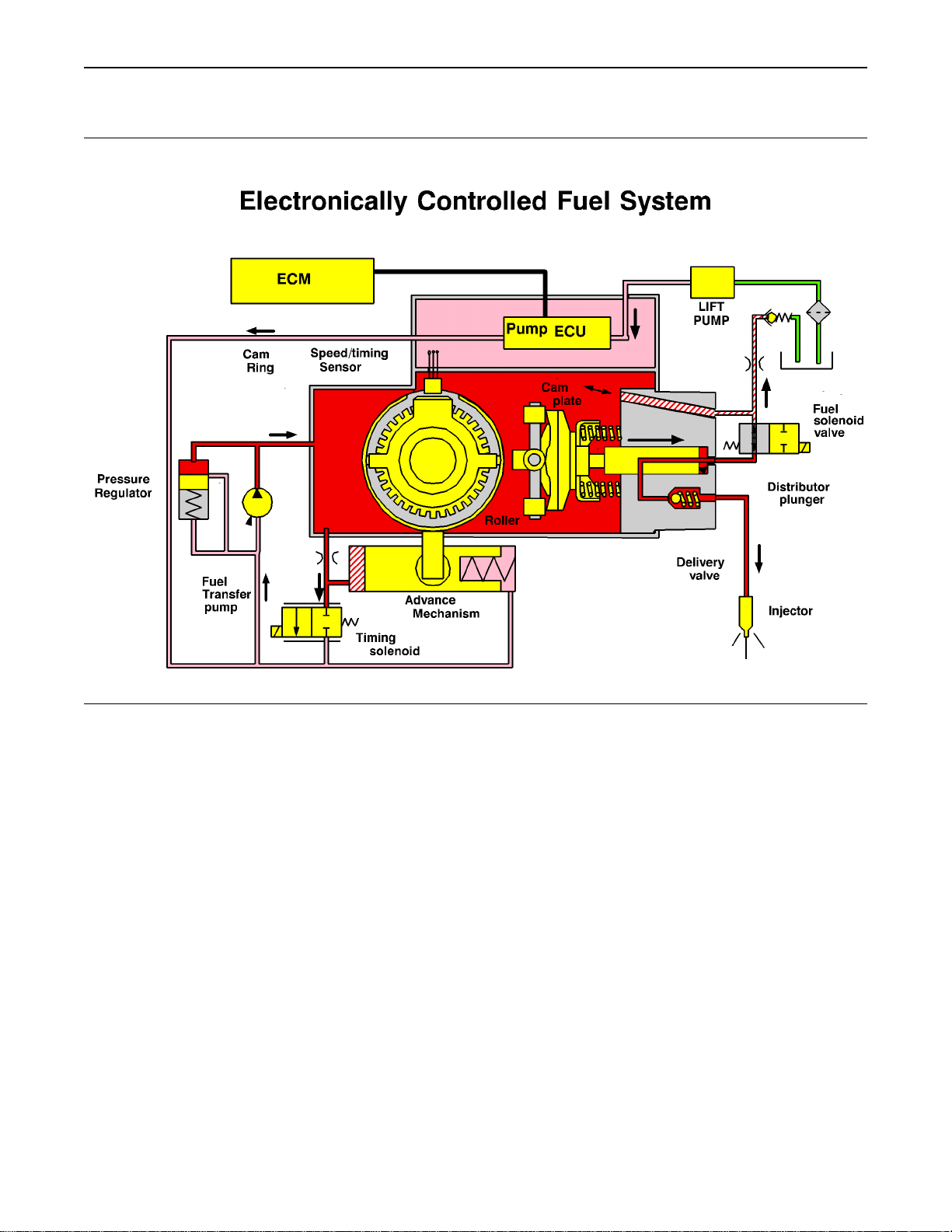
System Overview
System Operation
The 1104 models RF, RH, RK and 1106 model
VK engines were designed for electronic control.
The engines include an Electronic Control Module
(ECM), a fuel injection pump that is electronically
controlled, and a collection of engine sensors. The
ECM controls the engine operating parameters
through the software within the ECM and the inputs
from the various sensors. The software contains
parameters that control the engine operation. The
parameters include all of the operating maps and
customer selected parameters.
5
Troubleshooting Section
Page 5
6
Troubleshooting Section
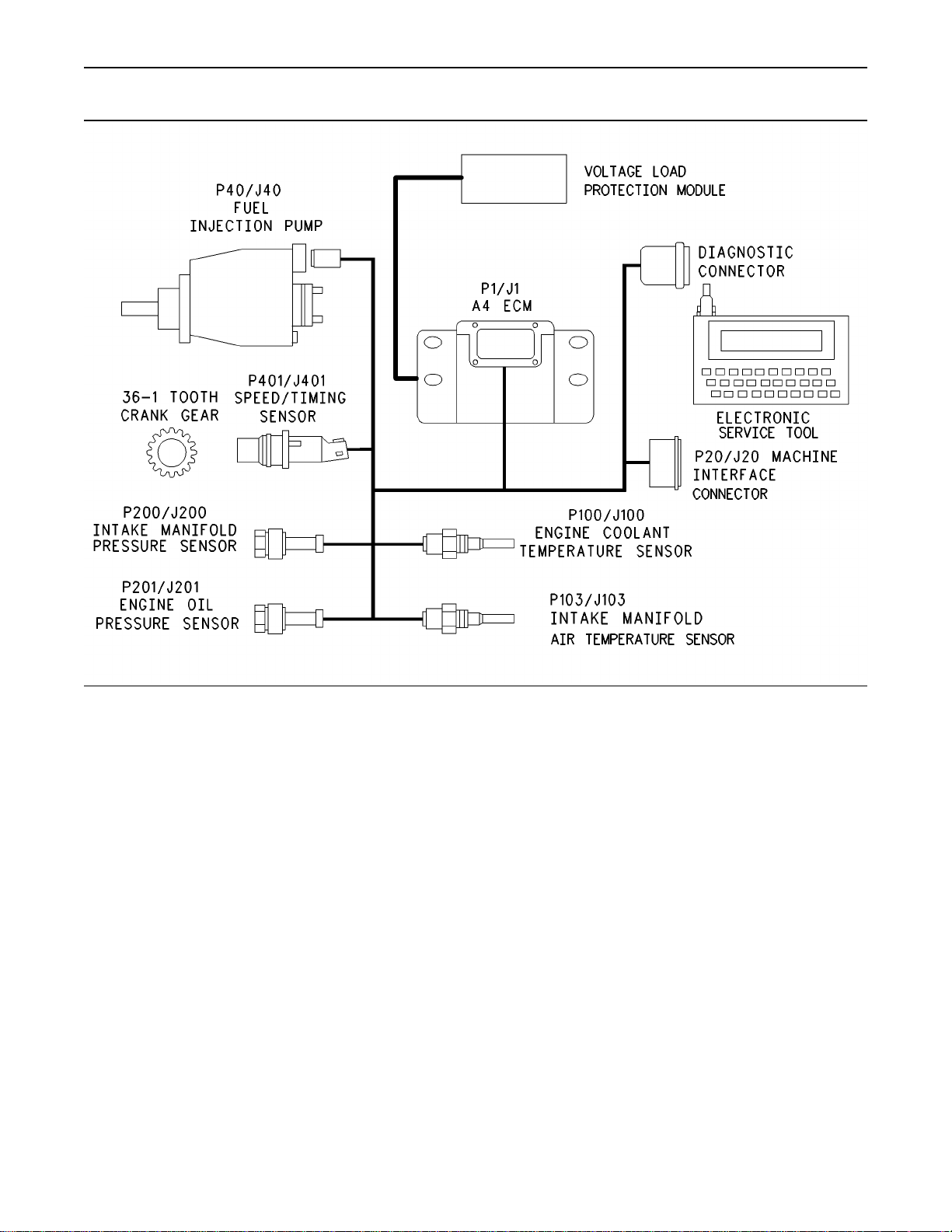
Electronic Controls
Illustration 1
g00908788
Page 6
Troubleshooting Section
7
Illustration 2
The electronic system consists of the Electronic
Control Module (ECM), the engine sensors, and the
Machine Interface Connector (MIC). The ECM is the
computer. The personality module is the software
for the computer. The personality module contains
the operating maps. The operating maps define the
following characteristics of the engine:
Horsepower
•
Torque curves
•
Engine speed (rpm)
•
Engine Governor
The electronic controls determine the injection
timing and the amount of fuel that is delivered to
the cylinders. These decisions are based on the
actual conditions and the desired conditions at any
given time.
g00954204
The governor compares the desired engine speed
to the actual engine speed. The actual engine
speed is determined through the crankshaft position
sensor. If the desired engine speed is greater than
the actual engine speed, the governor injects more
fuel in order to increase engine speed.
Timing Considerations
Once the governor has determined the amount of
fuel that is required, the governor must determine
the timing of the fuel injection. Fuel injection timing
is determined by the ECM after considering input
from the following components:
Engine coolant temperature sensor
•
The sensor for the intake manifold air temperature
•
The sensor for the intake manifold pressure
•
Page 7

8
Troubleshooting Section
At start-up, the ECM determines the top dead
center position of the number 1 cylinder from the
speed/timing sensor in the fuel injection pump.
The ECM decides when fuel injection should occur
relative to the top dead center position. The ECM
provides the signal to the fuel injection pump spill
valve which stops fuel flow to the low pressure side.
The ECM then forces fuel to flow to the fuel injector
nozzles at the desired time. The ECM adjusts timing
for the best engine performance, the best fuel
economy and the best control of exhaust emissions.
Actual timing cannot be viewed with an electronic
service tool. Also, the desired timing cannot be
viewed with an electronic service tool.
Fuel Injection
The personality module inside the ECM sets certain
limits on the amount of fuel that can be injected.
The FRC Limit is a limit that is based on intake
manifold air pressure and engine rpm. The FRC
Limit is used to control the air/fuel ratio in order to
control the engine’s exhaust emissions. When the
ECM senses a higher intake manifold air pressure,
the ECM increases the FRC Limit. A higher intake
manifold air pressure indicates that there is more air
in the cylinder. When the ECM increases the FRC
Limit, the ECM allows more fuel into the cylinder.
The Rated Fuel Limit is a limit that is based on the
power rating of the engine and on the engine rpm.
The Rated Fuel Limit enables the engine power and
torque outputs to conform to the power and torque
curves of a specific engine model.
These limits are in the personality module and these
limits cannot be changed.
Diagnostic Codes
When the ECM detects an engine problem, the ECM
generates a diagnostic code. Also, the ECM logs
the diagnostic code in order to indicate the time of
the problem’s occurrence. The ECM also logs the
number of occurrences of the problem. There are
two types of diagnostic fault codes. There are fault
codes and event codes.
Diagnostic Fault Codes
Diagnostic fault codes are provided in order to
indicate that an electrical problem or an electronic
problem has been detected by the ECM. In some
cases, the engine performance can be affected
when the condition that is causing the code exists.
More frequently, the operator cannot detect any
difference in the engine performance.
If the operator indicates that a performance problem
occurs, the diagnostic code may indicate the cause
of the problem. Use either a laptop computer or a
hand held diagnostic tool to access the diagnostic
codes. The problem should then be corrected.
If the operator does not indicate a problem with
the engine performance and a diagnostic code is
logged by the ECM. This situation indicates that
the ECM detected an abnormal engine condition,
but the abnormal condition did not affect engine
performance. In this situation, the system has no
faults except when either of the following conditions
exist:
There are several occurrences of the diagnostic
•
code in a very short period of time.
The ECM is indicating an active code at the
•
present time.
Diagnostic Event Codes
Diagnostic event codes are used to indicate that
some operational problem has been detected in
the engine by the ECM. This does not indicate an
electronic malfunction.
Programmable Parameters
Certain parameters that affect the engine operation
may be changed with electronic service tools.
The parameters are stored in the ECM, and the
parameters are protected from unauthorized
changes by passwords. These parameters are
System Configuration Parameters.
System Configuration Parameters are set at the
factory. System Configuration Parameters affect
emissions or power ratings within the engine.
Factory passwords must be obtained and factory
passwords must be used to change the System
Configuration Parameters.
Passwords
System Configuration Parameters are protected
by factory passwords. Factory passwords are
calculated on a computer system that is available
only to Perkins distributors. Since factory passwords
contain alphabetic characters, only an electronic
service tool may change System Configuration
Parameters. System Configuration Parameters affect
the power rating or the emissions.
Refer to Troubleshooting, “Programming Parameters”
and Troubleshooting, “Factory Passwords”.
Page 8

Troubleshooting Section
9
i01798101
Glossary
Active Diagnostic Code – An active diagnostic code
alerts the operator or the service technician that an
electronic system malfunction is currently present.
Refer to the term “Diagnostic Code” in this glossary.
Alternating Current (AC) – Alternating current is an
electric current that reverses direction at a regular
interval that is reoccurring.
Before Top Dead Center (BTC) – BTDC is the 180
degrees of crankshaft rotation before the piston
reaches the top dead center position in the normal
direction of rotation.
Boost Pressure (Engines that are turbocharged) –
The difference between the turbocharger outlet
pressure and atmospheric pressure is commonly
referred to as boost pressure. The sensor for the
intake manifold air pressure measures the amount
of boost.
Breakout Harness – The breakout harness is a
test harness that is designed to connect into the
engine harness. This connection allows a normal
circuit operation and the connection simultaneously
provides a Breakout T in order to measure the
signals.
Bypass Circuit – A bypass circuit is a circuit that is
used as a substitute circuit for an existing circuit. A
bypass circuit is typically used as a test circuit.
CAN Data Link – The CAN Data Link is a serial
communications port that is used for communication
with other microprocessor based devices. In this
application, the CAN Data Link connects the ECM
to the Electronic Fuel Injection Pump.
Code – Refer to “Diagnostic Code” or “Event Code”.
Cold Mode – Cold mode is a mode for cold starting
and for cold engine operation that includes timing
that is retarded and low idle that is raised. This
mode is used for engine protection, reduced smoke
emissions and faster warm up time.
Communication Adapter Tool – The communication
adapter provides a communication link between the
ECM and the Electronic Service Tool.
Coolant Level Sensor – The coolant level sensor
detects the absence or presence of coolant at the
probe. The sensor then sends a signal to the ECM.
Coolant Temperature Sensor – The coolant
temperature sensor detects the engine coolant
temperature for cold mode operation and for Engine
Monitoring.
Data Link – The Data Link is a serial communication
port that is used for communication with other
microprocessor based devices.
Desired Engine Speed – The desired engine speed
is input to the electronic governor within the ECM.
The electronic governor uses the signal from the
throttle position sensor, the engine speed/timing
sensor, and other sensors in order to determine the
desired engine speed.
Diagnostic Code – A diagnostic code is sometimes
referred to as a fault code. These codes indicate an
electronic system malfunction.
Diagnostic Lamp – A diagnostic lamp is sometimes
called the check engine light. The diagnostic lamp
is used to warn the operator of the presence of an
active diagnostic code.
Digital Sensor Return – The common line (ground)
from the ECM is used as ground for the digital
sensors.
Digital Sensors – Digital sensors produce a pulse
width modulated signal. Digital sensors are supplied
with +8 VDC from the ECM.
Digital Sensor Supply – The +8 VDC supply from the
ECM is used in order to power the digital sensors.
Direct Current (DC) – Direct current is the type of
current that flows consistently in only one direction.
DT, DT Connector, or Deutsch DT – This is a type
of connector that is used on Perkins engines. The
connectors are manufactured by Deutsch.
Duty Cycle – Refer to “Pulse Width Modulation”.
Electronic Engine Control – The electronic engine
control is a complete electronic system. The
electronic engine control monitors the engine
operation under all conditions. The electronic
engine control also controls the engine operation
under all conditions.
Component Identifier (CID) – The CID is a number
that identifies the specific component of the
electronic control system that has experienced a
diagnostic code.
Electronic Service Tool – The electronic service tool
allows a computer (PC) to communicate with the
ECM.
Page 9

10
Troubleshooting Section
Electronic Control Module (ECM) – The ECM is the
control computer of the engine. The ECM provides
power to the electronics. The ECM monitors data
that is input from the sensors of the engine. The
ECM acts as a governor in order to control the
speed and the power of the engine.
Engine Monitoring – Engine Monitoring is the part
of the electronic engine control that monitors the
sensors. This also warns the operator of detected
problems.
Engine Oil Pressure Sensor – The engine oil
pressure sensor measures engine oil pressure. The
sensor sends the signal to the ECM.
Engine Speed/Timing Sensor – The engine
speed/timing sensor provides a variable amplitude
and pulse width modulated signal to the ECM. The
ECM interprets this signal as the crankshaft position
and the engine speed.
Event Code – An event code may be activated in
order to indicate an abnormal engine operating
condition. These codes usually indicate a
mechanical problem instead of an electrical system
problem.
Failure Mode Identifier (FMI) – This identifier
indicates the type of failure that has been
experienced by the component. The FMI has
been adopted from the SAE practice of J1587
diagnostics.
Flash Programming – Flash programming is the
method of programming or updating an ECM with
an electronic service tool over the data link instead
of replacing components.
Fuel Ratio Control (FRC) – The FRC is a limit that is
based on the control of the ratio of the fuel to air.
The FRC is used for purposes of emission control.
When the ECM senses a higher intake manifold
air pressure (more air into the cylinder), the FRC
increases the FRC Limit (more fuel into the cylinder).
Fuel Temperature Sensor – The fuel temperature
sensor detects the fuel temperature. The ECM
monitors the fuel temperature and the ECM adjusts
the calculated fuel rate accordingly.
Full Load Setting (FLS) – The FLS is the number
that represents the fuel system adjustment. This
adjustment is made at the factory in order to fine
tune the fuel system. The correct value for this
parameter is stamped on the engine information
ratings plate. This parameter must be programmed.
Harness – The harness is the bundle of wiring
(loom) that connects all components of the
electronic system.
Hertz (Hz) – Hertz is the measure of electrical
frequency in cycles per second.
Intake Manifold Air Temperature Sensor – The
intake manifold air temperature sensor detects the
air temperature in the intake manifold. The ECM
monitors the air temperature and other data in the
intake manifold in order to adjust injection timing
and other performance functions.
Intake Manifold Pressure Sensor – The air pressure
in the intake manifold may be different to the
air pressure outside the engine (atmospheric
pressure). This difference in air pressure can be
caused by variable air velocity within the manifold.
The difference in pressure can also be caused
by an increase in air pressure by a turbocharger
(if equipped). The sensor for the intake manifold
air pressure measures the difference between
atmospheric pressure and the air pressure in the
intake manifold.
Integrated Electronic Controls – The engine is
designed with the electronic controls as a necessary
part of the system. The engine will not operate
without the electronic controls.
J1939 CAN Data Link – This data link is a SAE
diagnostic communications data link that is used to
communicate between the ECM and the electronic
service tool.
Logged Diagnostic Codes – Logged diagnostic
codes are codes which are stored in the memory.
These codes are meant to be an indicator of
possible causes for intermittent problems. Refer to
the term “Diagnostic Code” in this glossary for more
information.
MAB – This is a Bosch acronym for the fuel shutoff
inside the “VPM30” Fuel Injection Pump. The MAB
is a signal wire from the ECM to the Fuel Injection
Pump.
Open Circuit – An open circuit is a condition that is
caused by an open switch, or by an electrical wire
or a connection that is broken. When this condition
exists, the signal or the supply voltage can no
longer reach the intended destination.
Parameter – A parameter is a value or a limit that
is programmable. This helps determine specific
characteristics or behaviors of the engine.
Full Torque Setting (FTS) – The FTS is similar
to the full load setting. This parameter must be
programmed.
Page 10
11
Troubleshooting Section
Password – A password is a group of numeric
characters or a group of alphanumeric characters
that is designed to restrict access to parameters.
The electronic system requires correct passwords
in order to change some parameters (Factory
Passwords). Refer to Troubleshooting, “Factory
Passwords” for more information.
Personality Module – This module is inside the
ECM. The module contains all the instructions
(software) for the ECM and the module contains
the performance maps for a specific engine. The
personality module may be reprogrammed through
flash programming.
Power Cycled – Power cycled happens when power
to the ECM is cycled: ON, OFF, and ON. Power
cycled refers to the action of cycling the keyswitch
from any position to the OFF position, and to the
START/RUN position.
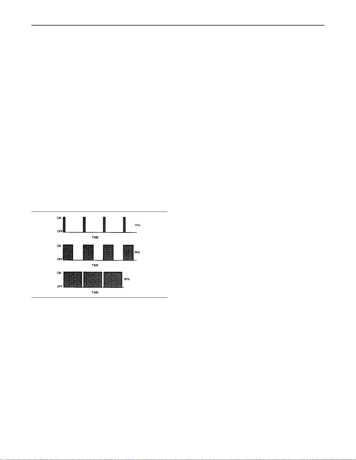
Pulse Width Modulation (PWM) – The PWM is a
signal that consists of pulses that are of variable
width. These pulses occur at fixed intervals. The
ratio of “TIME ON” versus total “TIME OFF” can be
varied. This ratio is also referred to as a duty cycle.
Short Circuit – A short circuit is a condition that has
an electrical circuit that is inadvertently connected
to an undesirable point. An example of a short
circuit is a wire which rubs against a vehicle frame
and this rubbing eventually wears off the wire
insulation. Electrical contact with the frame is made
and a short circuit results.
Signal – The signal is a voltage or a waveform that
is used in order to transmit information typically
from a sensor to the ECM.
Supply Voltage – The supply voltage is a constant
voltage that is supplied to a component in order
to provide the electrical power that is required for
the component to operate. The power may be
generated by the ECM or the power may be battery
voltage that is supplied by the engine wiring.
System Configuration Parameters – System
configuration parameters are parameters that affect
emissions and/or operating characteristics of the
engine.
Throttle Position – The throttle position is the
interpretation by the ECM of the signal from the
throttle position sensor or the throttle switch.
Illustration 3
g00284479
Rated Fuel Limit – This term indicates the maximum
allowable fuel position (longest injection pulse). This
position will produce rated power for this engine
configuration.
Reference Voltage – Reference voltage is a
regulated voltage and a steady voltage that is
supplied by the ECM to a sensor. The reference
voltage is used by the sensor to generate a signal
voltage.
Sensor – A sensor is a device that is used to detect
a change in pressure, temperature, or mechanical
movement. The information that is detected is
converted into an electrical signal.
Throttle Position Sensor – The throttle position
sensor is an electronic sensor that is connected to
an accelerator pedal or a hand lever. This sensor
sends a PWM signal to the ECM that is used to
calculate desired engine speed.
Throttle Switch – The throttle switch sends a signal
to the ECM that is used to calculate desired engine
speed.
Top Dead Center – Top dead center refers to the
crankshaft position when the engine piston position
is at the highest point of travel. The engine must be
turned in the normal direction of rotation in order
to reach this point.
Total Tattletale – The total tattletale is the total
number of changes to all the parameters that are
stored in the ECM.
Voltage Load Protection Module (“VLPM”) – The
“VLPM” monitors the voltage of the electronic
system. The “VLPM”will eliminate any high voltage
conditions that occur. The “VLPM” will protect the
fuel injection pump from any high voltage conditions
that could damage the pump.
Page 11

12
Troubleshooting Section
i01798102
Electronic Service Tools
Electronic Service Tools are designed to help the
service technician with the diagnosis and repair of
electronic engines. Several tools are available to
assist the service technician.
Some of the included Diagnostic Functional Tests
in this manual require two short jumper wires. The
jumper wires are used to check the continuity
of some wiring harness circuits by shorting two
adjacent terminals together in a connector.
A long extension wire may also be needed to check
the continuity of some wiring harness circuits.
Electronic Service Tool
The electronic service tool can display the following
information:
Parameters
•
Event codes
•
Diagnostic codes
•
Ta bl e 1
Required Electronic Service Tools for the Use
Part
Number
of the Electronic Service Tool
Required
IBM compatible PC with
266 MHz Pentium processor
64 MB of RAM
N/A
N/A
400 MB of available hard drive space
CD-ROM drive
3.5" 1.44 MB floppy disk drive
VGA monitor or display (800 x 600)
Microsoft
NT 4.0, 98, or 95
RS232 port with 16550AF UART
Recommended
IBM compatible PC with
450 MHz Pentium III processor
128 MB of RAM
1 GB of available hard drive space
40X speed CD-ROM drive or
8X speed DVD drive
3.5" 1.44 MB floppy disk drive
Super VGA monitor or display (800 x 600)
Microsoft
NT 4.0, or 98
RS232 port with 16550AF UART
®
Windows 2000, XP, ME,
®
Windows 2000, XP, ME,
Description
Engine configuration
•
The electronic service tool can be used by the
technician to perform the following functions:
Diagnostic tests
•
Sensor calibrations
•
Flash programming
•
Set parameters
•
The following components are required to use the
electronic service tool to service the engine.
Page 12
13
Troubleshooting Section
Connecting the Electronic Service Tool
and the Communication Adapter II
Support for the Electronic Service Tool
For authorization and ordering information, contact
Perkins Help Desk - Irlam.
If you are having problems with the software, you
can contact the Perkins Service Systems Support
Center.
Optional Service Tools
The following table contains service tools that may
be helpful to service the engine.
Ta bl e 2
Optional Service Tools
Part Number Description
N/A
N/A Suitable Breakout T (70 pin)
N/A Suitable Crimp Tool
N/A Suitable Cylinder Pressure Indicator
N/A Suitable Battery Load Tester
Suitable Digital Multimeter
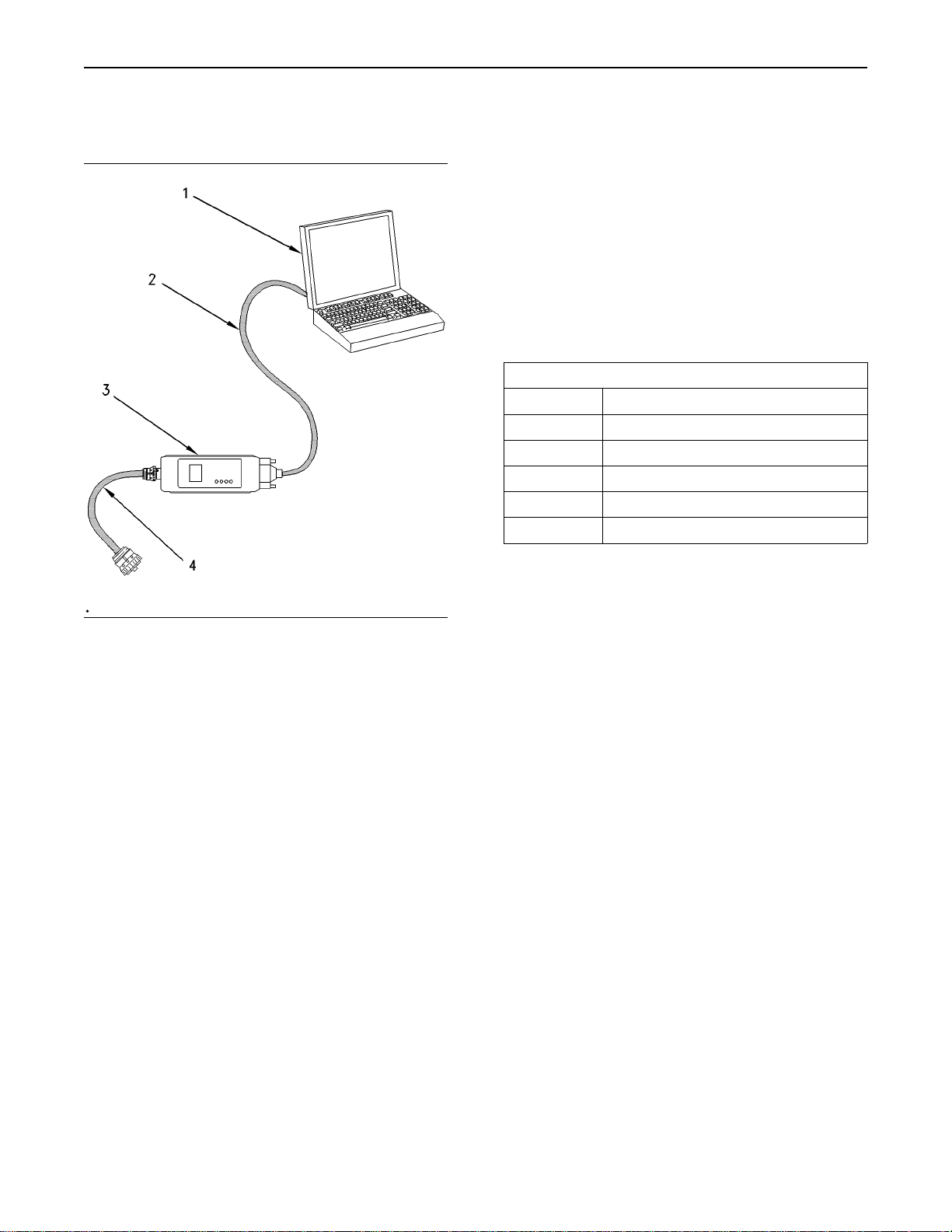
Illustration 4
(1) Personal computer (PC)
(2) Adapter Cable (Computer Serial Port)
(3) Communication Adapter II
(4) Adapter Cable Assembly
g00647144
Note: Items (2), (3), and (4) are part of the
Communication Adapter II Gp.
Use the following procedure to connect the
Electronic Service Tool and the Communication
Adapter II.
1. Turn the keyswitch to the OFF/RESET position. If
the keyswitch is not placed in the OFF/RESET
position, the engine may start.
2. Connect cable (2) between the “COMPUTER”
end of communication adapter (3) and the
RS232 serial port of PC (1).
3. Connect cable (4) between the “DATA LINK” end
of communication adapter (3) and the service
tool connector.
4. Turn the keyswitch to the ON position. If the
electronic service tool and the communication
adapter do not communicate with the ECM, refer
to Troubleshooting, “Electronic Service Tool Will
Not Communicate With ECM”.
i01879254
Diagnostic Codes
This list identifies the respective faults for the CID
FMI and the J Code FMI codes. The CID FMI codes
are displayed on a laptop computer. The J Code
FMI codes are displayed on a Diagnostic Code
Reader. The Diagnostic Code Reader is also known
as the Hand Held Tool.
The Component Identifier (CID) is a number that
identifies the specific component that caused a
diagnostic code to be logged.
The Failure Mode Identifier (FMI) is a number
that indicates the type of failure that has been
experienced by the component.
The J1939 Code is another system that identifies
the specific component that caused a diagnostic
code to be logged.
Note: Event codes are not supported by J1939
numbers. Event codes use (CID) and (FMI)
numbers. The following (FMI) numbers 0, 1, 15, 16,
17, and 18 are used for event codes.
Page 13

14
Troubleshooting Section
Ta bl e 3
CID FMI Code
0041 03
0041 04
0091 02
0091 03
0091 04
0091 08
0091 12
0100 03
0100 04
0100 10
0102 03
0102 04
0102 10
0105 03
0105 04
0110 03
0110 04
0168 02
0174 02
0247 09
0253 02
0262 03
0262 04
0266 02
0267 02
0320 02
0320 11
0321 02
0342 02
0590 02
0774 02
0774 03
0774 04
0774 08
0774 12
1627 03
1639 09
1684 00
J Code FMI Code Fault Description
J0678 03 8V Sensor Power Supply, voltage more than normal
J0678 04 8V Sensor Power Supply, voltage less than normal
J0091 02 Throttle Demand Sensor, erratic or intermittent
J0091 03 Throttle Demand Sensor, open circuit or shorted high
J0091 04 Throttle Demand Sensor, shorted low
J0091 08 Throttle Demand Sensor, abnormal signal
J0091-12 Throttle Demand Sensor, power supply failure
J0100 03 Engine Oil Pressure Sensor, open circuit or shorted high
J0100 04 Engine Oil Pressue Sensor, shorted low
Engine Oil Pressure Sensor, power supply open circuit
J0102 03 Intake Manifold Pressure Sensor, open circuit or shorted high
J0102 04 Intake Manifold Pressure Sensor, shorted low
Intake Manifold Pressure Sensor, power supply open circuit
J0105 03 Intake Manifold Temperature Sensor, open circuit or shorted high
J0105 04 Intake Manifold Temperature Sensor, shorted low
J0110 03 Engine Coolant Temperature Sensor, open circuit or shorted high
J0110 04 Engine Coolant Temperature Sensor, shorted low
J0168 02 Battery Voltage, intermittent or incorrect
J0174 02 Fuel Temperature Sensor, erratic or intermittent
J0639 09 J1939 Datalink, abnormal update
J0234 02 Incorrect ECM Software
J0620 03 5V Sensor Power Supply, voltage more than normal
J0620 04 5V Sensor Power Supply, voltage less than normal
Crank without injection, switch state incorrect
External Stop Switch, data erratic or incorrect
J0637 02 Speed and Timing Sensor, intermittent loss of signal
J0637 11 Speed and Timing Sensor, loss of signal
Diagnostic Reset Switch, intermittent or incorrect
J0723 02 Speed and Timing Sensor No.2, intermittent signal
ECM identified missing timing pulse
Throttle Demand Sensor No.2, erratic or intermittent
Throttle Demand Sensor No.2, open circuit or shorted high
Throttle Demand Sensor No.2, shorted low
Throttle Demand Sensor No.2, abnormal signal
Throttle Demand Sensor No.2, power supply failure
Fuel Pump Relay, did not turn off
Machine Security System Module, abnormal update
J1077 00 Fuel Injection Pump, fuel temperature more than normal
(continued)
Page 14

(Table 3, contd)
1684 02
1684 03
1684 04
1684 05
1684 07
1684 08
1684 09
1684 10
1684 11
1684 12
1684 14
1690 08
1743 02
1894 02
1895 02
Event Code CID FMI Code
E015
E016
E017
E025
E027
E039
E040
E054
E056
E100
E190
E442 Engine Failed To Stop With A No-Fuel Command
E883 Engine Failed To Stop When Fuel Solenoid Disengaged
J1077 02 Fuel Injection Pump, software failure
J1077 03 Fuel Injection Pump, fuelling fault
J1077 04 Fuel Injection Pump, supply voltage fault
J1077 05 Fuel Injection Pump, invalid pulse width
J1077 07 Fuel Injection Pump, mechanical fault
J1077 08 Fuel Injection Pump, crankshaft reference fault
J1077 09 Fuel Injection Pump, CAN fault
J1077 10 Fuel Injection Pump, fuel shutoff signal error
J1077 11 Fuel Injection Pump, internal sensor fault
J1077 12 Fuel Injection Pump, device failure
J1077 14 Fuel Injection Pump, no communications
Analogue Speed Control, signal abnormal
Engine Mode Selection Switch State, invalid state
Set Speed Control Disengage Switch, invalid state
Set Speed Control Speed Toggle Switch, invalid state
110 16
110 00
110 15
105 16
105 15
100 18
100 01
174 16
174 15
100 17
190 15
High Engine Coolant Temperature Derate
High Engine Coolant Temperature Sutdown
High Engine Coolant Temperature Warning
High Intake Air Temperature Derate
High Intake Air Temperature Warning
Low Engine Oil Pressure Derate
Low Engine Oil Pressure Shutdown
High Fuel Temperature Derate
High Fuel Temperature Warning
Low Engine Oil Pressure Warning
Engine Overspeed Warning
15
Troubleshooting Section
i01878735
Indicator Lamps
Some engine applications are equipped with
Indicator Lamps. Indicator lamps can be used as a
diagnostic aid. There are two lamps. One lamp has
an orange lens and the other lamp has a red lens.
These indicator lamps can be used in two ways:
The indicator lamps can be used to identify the
•
current operational status of the engine. The
indicator lamps can also be used to indicate
that the engine has a fault. This system is
automatically operated via the ignition switch.
The indicator lamps can be used to identify active
•
diagnostic codes. This system is activated by
pressing the Flash Code button.
Page 15

16
Troubleshooting Section
Use the lamps to check the engine’s
operational status or the existence
of any engine faults.
Each lamp will be illuminated in a combination of
ways in order to identify the engine’s operational
status. The lamps will also be illuminated in a
combination of ways to indicate if the engine has a
fault. These combinations of illuminated lamps have
the following meanings:
The status of the lamps before the engine is
cranked. This also acts as a lamp check.
When the ignition switch is turned ON, the lamps
will be illuminated for 2 seconds. The lamps are
then OFF unless the cold starting aid is required.
Ta bl e 4
Orange
lamp
(status)
ON ON The lamps will be illuminated
Refer to the
comments.
The lamp status with the cold starting aid in
operation and before the engine is cranked.
Red lamp
(status)
for 2 seconds or the lamps
will be illuminated until the
engine is cranked.
OFF The lamp will be OFF unless
the cold starting aid is
required.
Comments
Ta bl e 6
Orange
lamp
(status)
OFF OFF There are no apparent
ON ON The lubricating oil pressure
Red lamp
(status)
Comments
problems.
is low. This low oil pressure
was measured after the set
delay had expired.
The status of the lamps after cranking has failed
to start the engine.
Ta bl e 7
Orange
lamp
(status)
OFF OFF No faults were detected.
ON OFF An electrical fault was
OFF Flashing The engine was activated
Red lamp
(status)
Comments
detected.
when a serious fault was
detected.
Other combinations of illuminated indicator lamp
The following combinations of lamp status may also
be exhibited when the engine is either running or
when the engine has been shut down automatically.
The orange lamp will be illuminated until the engine
is ready to be cranked.
Ta bl e 5
Orange
lamp
(status)
ON OFF The status of the lamps with
Then OFF OFF This is the status of the
Red lamp
(status)
Comments
the cold starting aid still
operating.
lamps while the engine is
being cranked. The cold
starting aid is no longer
operating.
This is the status of the lamps while the engine
is being cranked.
Unless there is a fault, the engine monitoring system
will not illuminate the indicator lamps while the
engine is being cranked. For example if there is a
lack of lubricating oil pressure after the start delay
is exceeded. This type of fault will cause the stop
lamp for the engine to be illuminated.
Page 16

17
Troubleshooting Section
Ta bl e 8
Orange
lamp
(status)
OFF OFF No faults were detected.
OFF ON The oil pressure is low.
Flashing OFF Either the coolant temperature
OFF Flashing Either a fault has caused the
ON OFF An electrical fault has been
ON ON The oil pressure is low and
ON Flashing Either a fault has caused the
Flashing ON The oil pressure is low and
Red lamp
(status)
Comments
is high or the intake air
temperature is high. The
engine may be derated.
engine to be automatically
shut down or the engine has
exceeded the condition for a
derate.
detected.
there is an electrical fault.
engine to shut down or the
engine has exceeded the
conditions for a derate. There
is also an electrical fault.
either the coolant temperature
or the intake air temperature
is high. The engine may be
derated.
Use the lamps to identify active
diagnostic codes.
Ta bl e 9
CID
number
0041
0091
0100
0102
0105
0110
0174
0247
0253
0262
0320
0342
0774
1684
1743
1894
1895
Description Flash
8 Volt Power Supply
Throttle Position Sensor
Engine Oil Pressure Sensor
Intake Manifold Pressure
Sensor
Intake Manifold Air Temperature
Sensor
Engine Coolant Temperature
Sensor
Fuel Temperature Sensor
J1939 Data Link
Personality Module
5 Volt Power Supply
Engine Speed/Timing Sensor
Secondary Engine Speed
Sensor
Secondary Throttle Position
Sensor
Fuel Injection Pump
Mode Selector Switch for
Engine Operation
Cruise Control Status Switch
Toggle Switch for Cruise
Control Speed
code
517
154
157
135
133
168
165
514
416
516
141
142
155
158
144
427
428
The indicator lamps can be used to identify an
active code by flashing in a sequence that will
identify the active code. The active code that
is flashed by the indicator lamps is only the
component identifier (CID). The indicator lamps
cannot identify the fault with the component. The
active code that is flashed by the indicator lamps is
not a Failure Mode Identifier (FMI).
When the Flash Code feature is activated the
indicator lamps will flash the codes of all active
codes. Activation of the indicator lamps is achieved
by cycling the keyswitch OFF and ON twice within
3 seconds.
There will be a delay of 2 seconds before the lamps
start to flash the identity of any active code.
An active CID with two digits will be flashed in
the following sequence. There will be a number of
flashes. The number of flashes will equal the first
digit. There will be a delay before a second number
of flashes. The second number of flashes will equal
the second digit. For example, a CID code of 41 will
be four flashes, a delay and the one flash. A three
digit CID code will have two delays between the
sequence of flashes. A four digit CID code will have
three delays between the sequence of flashes.
Each flash of the lamp will be 0.5 seconds long.
There will be a delay between each flash of 0.3
seconds.
Page 17

18
Troubleshooting Section
Each delay between each digit of the code will be
2 seconds.
After one active code has been identified there will
be a delay of 5 seconds before the next active
code is flashed.
The sequence of flashing the active codes may be
restarted at any time by reactivating the cycling of
the keyswitch.
i01798103
Replacing the ECM
NOTICE
Keep all parts clean from contaminants.
Contaminants may cause rapid wear and shortened
component life.
The engine is equipped with an Electronic Control
Module (ECM). The ECM contains no moving
parts. Follow the troubleshooting procedures in this
manual in order to be sure that replacing the ECM
will correct the problem. Verify that the suspect
ECM is the cause of the problem.
Note: Ensure that the ECM is receiving power
and that the ECM is properly grounded before
replacement of the ECM is attempted. Refer to
Troubleshooting, “Electrical Power Supply Circuit Test”.
A test ECM can be used in order to determine if
the ECM on the engine is faulty. Install a test ECM
in place of the suspect ECM. Flash the personality
module into the test ECM. Program the parameters
for the test ECM. The parameters must match
the parameters in the suspect ECM. Refer to the
following test steps for details. If the test ECM
resolves the problem, reconnect the suspect ECM.
Verify that the problem returns. If the problem
returns, replace the ECM.
Use the electronic service tool to read the
parameters in the suspect ECM. Record the
parameters in the suspect ECM. The personality
module can be flashed into the new ECM. After
the ECM is installed on the engine, the parameters
must be programmed into the new ECM.
Note: When a new ECM is not available, you may
need to remove an ECM from an engine that is
not in service. The ECM must have the same
serial number suffix. Ensure that the replacement
ECM and the Personality Module Interlock Code
match the suspect ECM. Be sure to record the
parameters from the replacement ECM. Use the
“Copy Configuration ECM Replacement” function in
the electronic service tool.
NOTICE
If the Personality Module and engine application are
not matched, engine damage may result.
Perform the following procedure in order to replace
the ECM.
1. Connect the electronic service tool to the service
tool connector.
2. Use the “Copy Configuration ECM Replacement”
function from the electronic service tool. If the
“Copy Configuration” is successful, proceed
to Step 4. If the “Copy Configuration” failed,
proceed to Step 3.
Note: You may want to record any Logged Faults
and Events for your records.
3. Record the parameters. Record all of the
parameters on the “Main Configuration” screen.
Also, record all of the parameters on the
“Throttle Configuration” screen and on the “Mode
Configuration” screen.
Note: If the parameters cannot be read, the
parameters must be obtained elsewhere. Some
parameters are stamped on the engine information
plate, but most parameters must be obtained from
the factory.
4. Remove the ECM.
a. Turn the keyswitch to the OFF position.
b. Turn the battery disconnect switch to the OFF
position.
c. Slacken the 4 mm Allen head screw
and disconnect the ECM 70-pin (P1/J1)
connectors.
d. Remove the mounting bolts from the ECM.
e. Disconnect the grounding strap from the ECM.
5. Install the replacement ECM.
Page 18

19
Troubleshooting Section
a. Use the old mounting hardware to install the
replacement ECM. The mounting hardware
should be free of damage.
b. Check that the ECM mounting hardware is
installed correctly. The rubber grommets are
used to protect the ECM from excessive
vibration. The ECM should be able to drift in
the rubber grommets.
c. Install the ground strap for the ECM on the
engine.
d. Reconnect the J1/P1 70 Pin connector to the
ECM. Tighten the Allen head screw on the
connectors to a torque of 6 N·m (55 lb in).
6. Download the Flash file.
a. Connect the electronic service tool to the
service connector.
b. Select “WinFlash” from the “Utilities” menu of
the electronic service tool.
c. Select the appropriate file.
7. If it is necessary, use the electronic service tool
to clear the rating interlock in the Personality
Module. To clear the rating interlock, enter the
factory password when the electronic service
tool is first connected. Activating the “Test ECM”
mode will also clear the rating interlock.
8. Use the electronic service tool to program the
parameters. Perform the following procedure.
a. If the “Copy Configuration” procedure was
successful, use the “Copy Configuration,
ECM Replacement” function to load the
configuration file into the ECM.
Event
•
Diagnostic Code – When a problem with the
electronic system is detected, the ECM generates a
diagnostic code. This indicates the specific problem
with the circuitry.
Diagnostic codes can have two different states:
Active
•
Logged
•
Active Code – An active diagnostic code indicates
that an active problem has been detected. Active
codes require immediate attention. Always service
active codes prior to servicing logged codes.
Logged Code – Every generated code is stored in
the permanent memory of the ECM. The codes are
logged.
Event Code – An event code is generated by
the detection of an abnormal engine operating
condition. For example, an event code will be
generated if the oil pressure is too low. In this case,
the event code indicates the symptom of a problem.
Logged codes may not indicate that a repair is
needed. The problem may have been temporary.
The problem may have been resolved since the
logging of the code. If the system is powered, it
is possible to generate an active diagnostic code
whenever a component is disconnected. When
the component is reconnected, the code is no
longer active. Logged codes may be useful to help
troubleshoot intermittent problems. Logged codes
can also be used to review the performance of the
engine and the electronic system.
b. If the “Copy Configuration” procedure failed,
configure the parameters individually. The
parameters should match the parameters
from step 2.
9. Check for logged diagnostic codes. Factory
passwords are required to clear Logged Events.
i01798104
Self-Diagnostics
The Electronic Control Module (ECM) has the ability
to detect problems with the electronic system
and with engine operation. When a problem is
detected, a code is generated. An alarm may also
be generated. There are two types of codes:
Diagnostic
•
Page 19
20
Troubleshooting Section
Sensors and Electrical
Connectors
i01798105
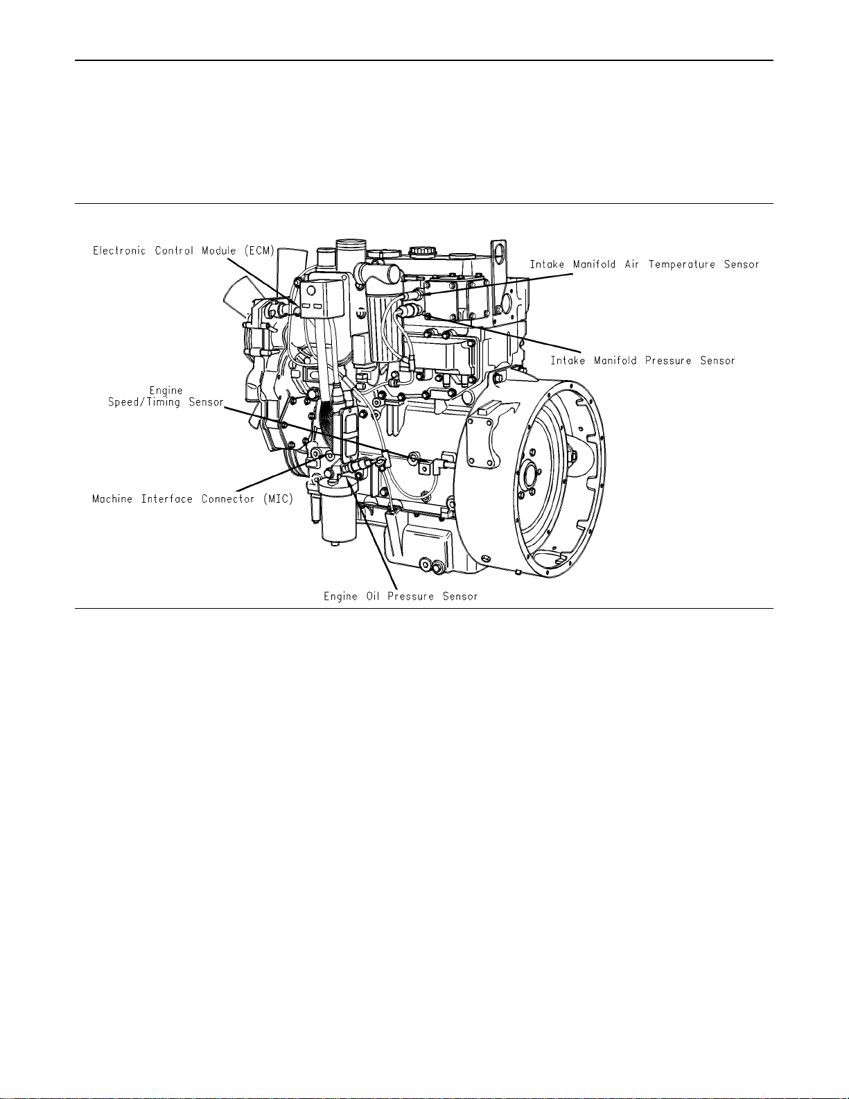
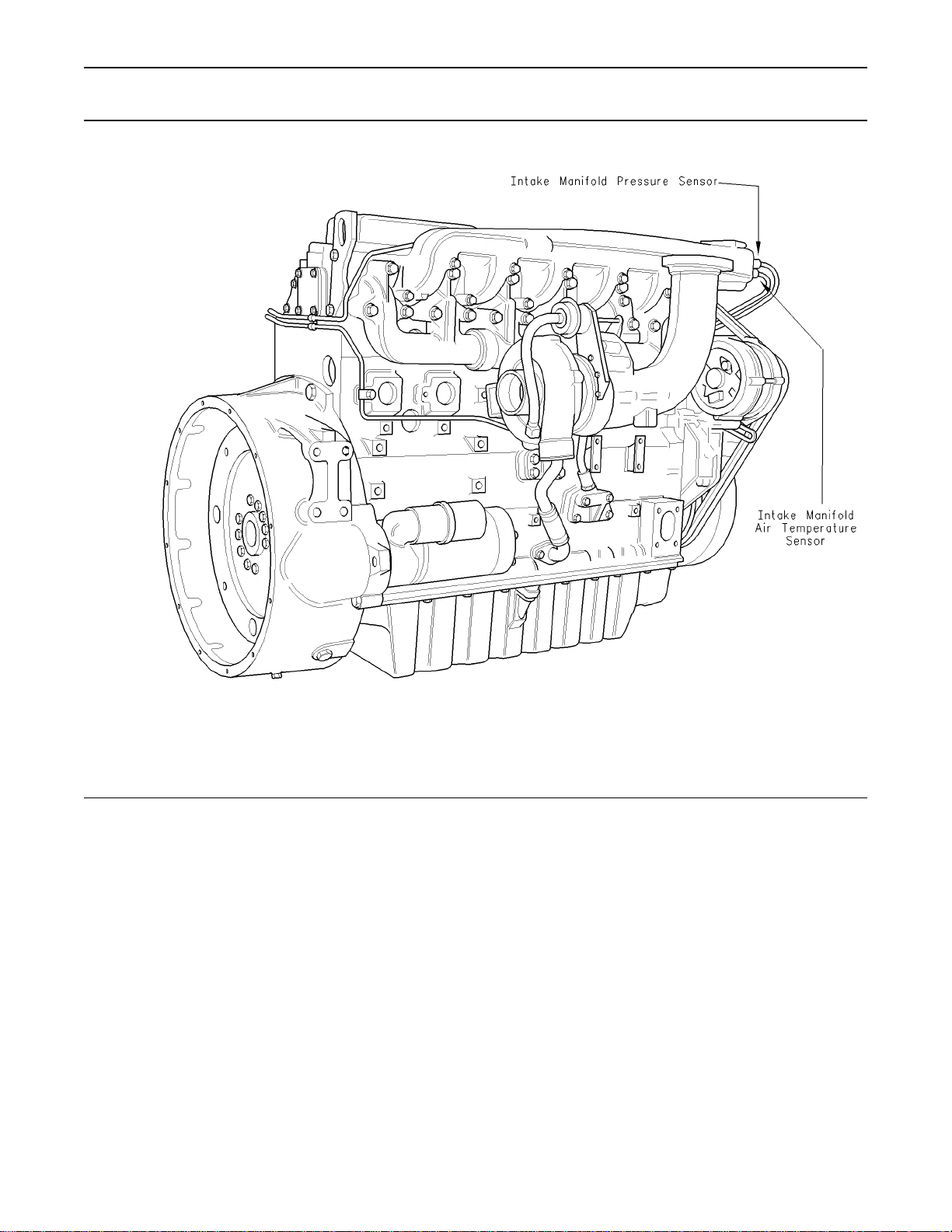
Illustration 5
1104
Typical example of left side sensor locations
g00954205
Page 20
21
Troubleshooting Section
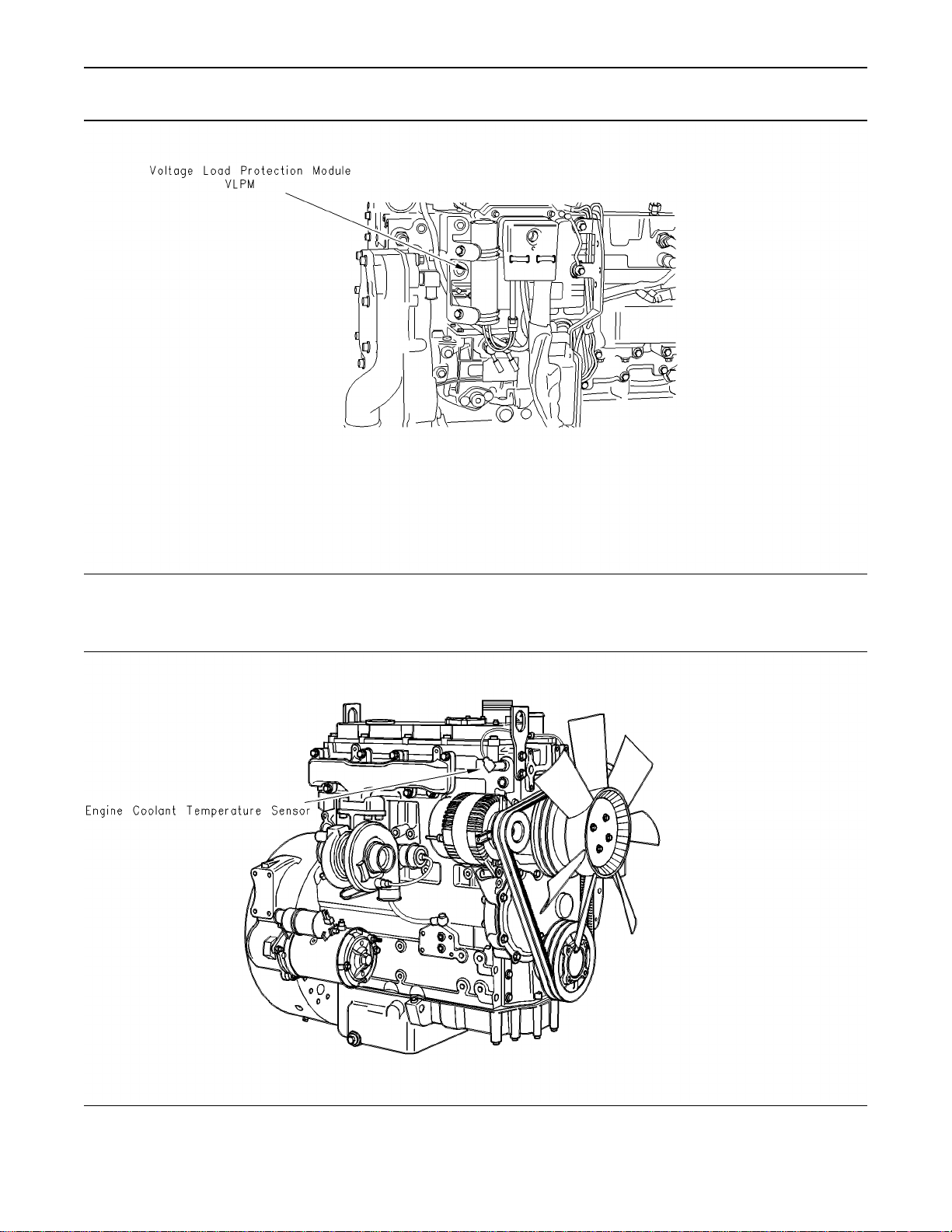
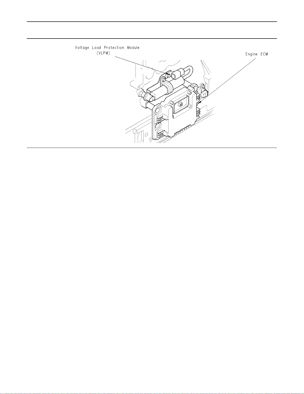
Illustration 6
1104 engine
Typical location of the VLPM
g00915379
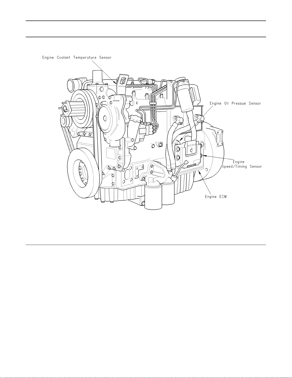
Illustration 7
1104
Typical example of right side sensor locations
g00882117
Page 21
22
Troubleshooting Section
Illustration 8
1106
Typical example of left side sensor locations
g00884570
Page 22
23
Troubleshooting Section
Illustration 9
1106 engine
Typical location of the VLPM
g00908929
Page 23
24
Troubleshooting Section
Illustration 10
Typical example of right side sensor locations
1106
g00954214
Page 24
Ta bl e 1 0
Connector
Function
J1/P1 ECM Connector 70 Pin Machine
Harness
J20/P20 Machine Interface Connector
(70-Pin Engine Harness)
J40/P40 Fuel Injection Pump (3-Pin
Connector)
J100/P100 Engine Coolant Temperature
Sensor (2-Pin Connector)
J103/P103 Intake Manifold Air Temperature
Sensor (2-Pin Connector)
J200/P200 Intake Manifold Pressure Sensor
(3-Pin Connector)
J201/P201 Engine Oil Pressure Sensor
(3-Pin Connector)
J401/P401 Speed/Timing Sensor (2-Pin
Connector)
25
Troubleshooting Section
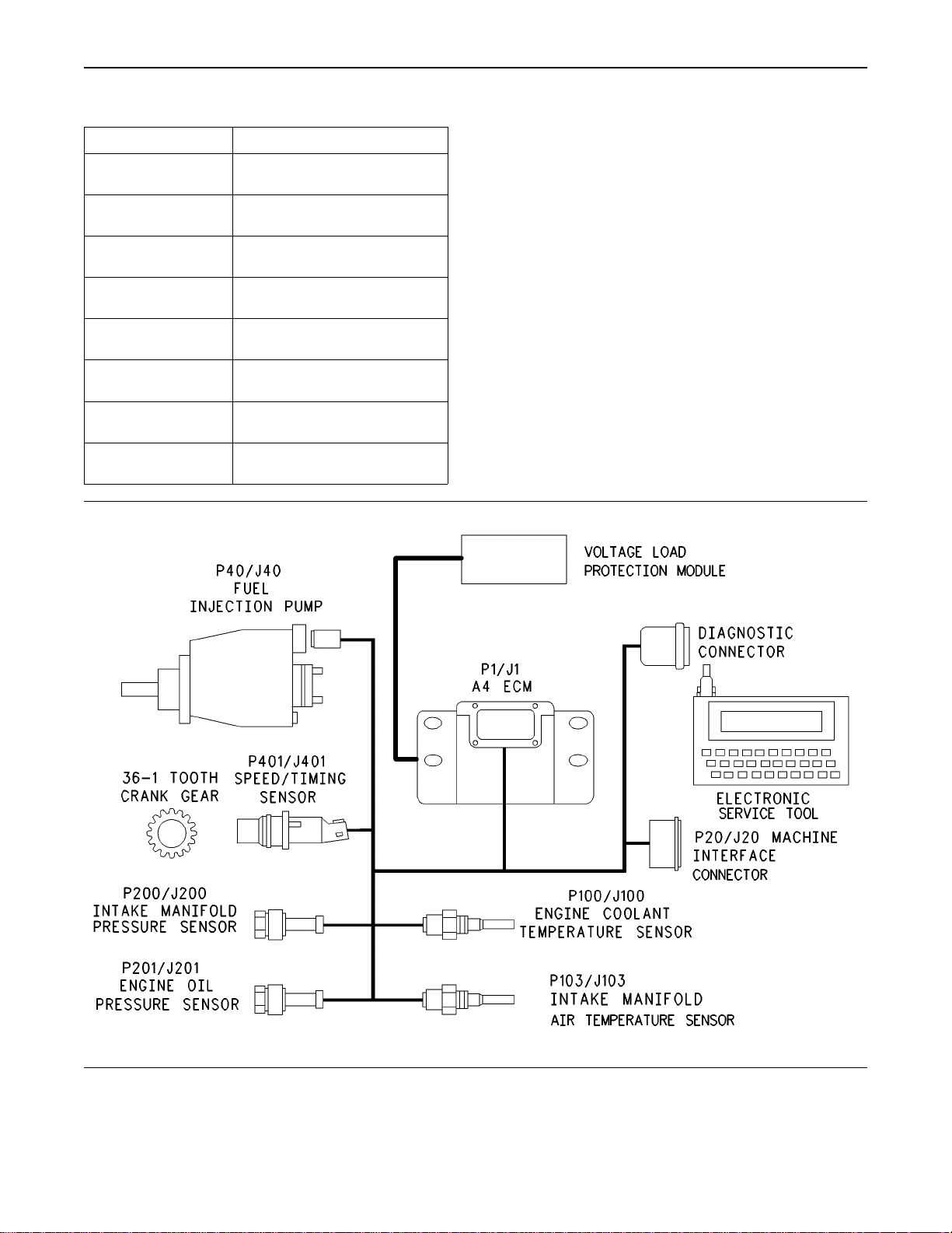
Illustration 11
Basic engine schematic
g00954204
Page 25
26
Troubleshooting Section
i01798106
Engine Wiring Information
The wiring diagrams are revised periodically. The
wiring diagrams will change with updates to the
wiring harness. For the most current information,
always check the revision number of the diagram.
Use the diagram with the latest revision number.
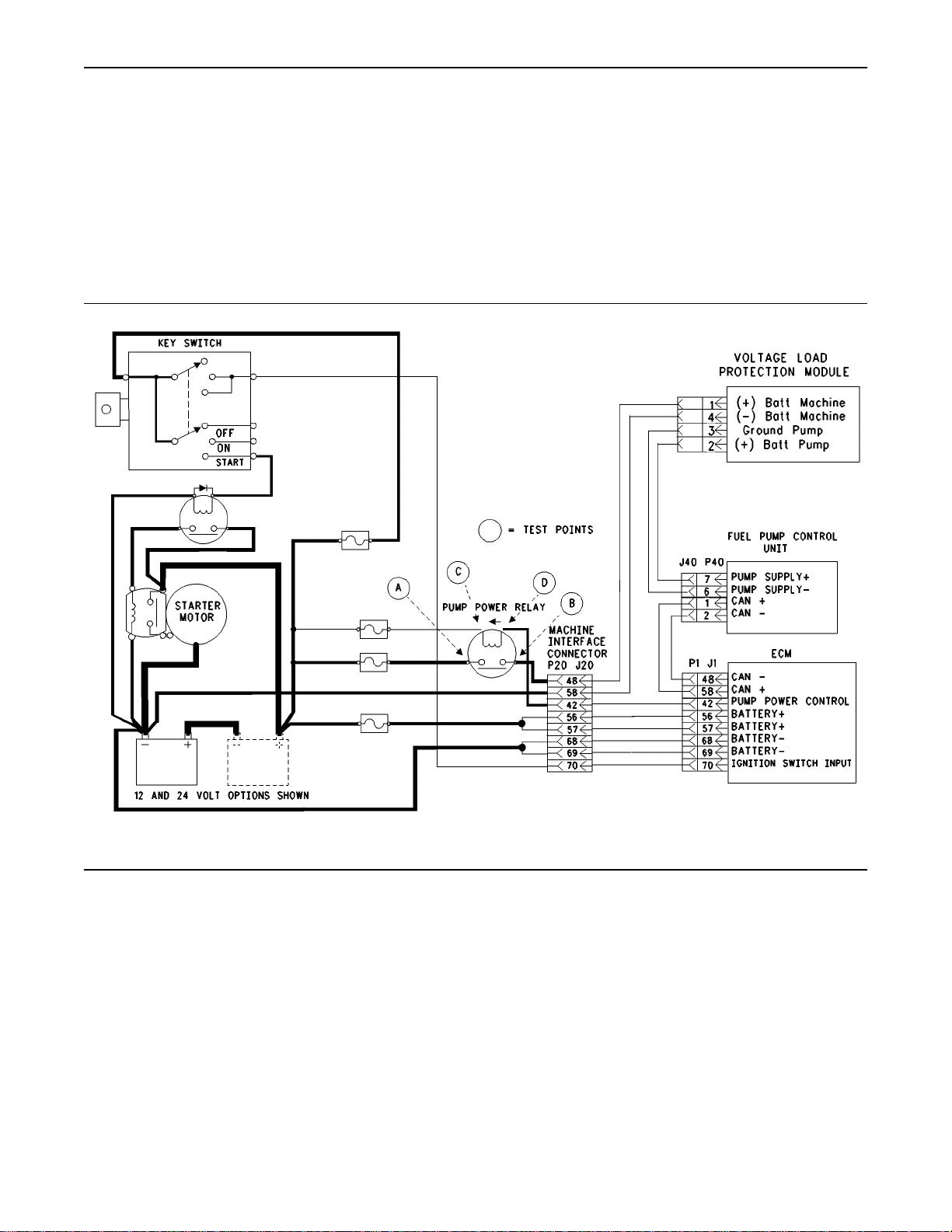
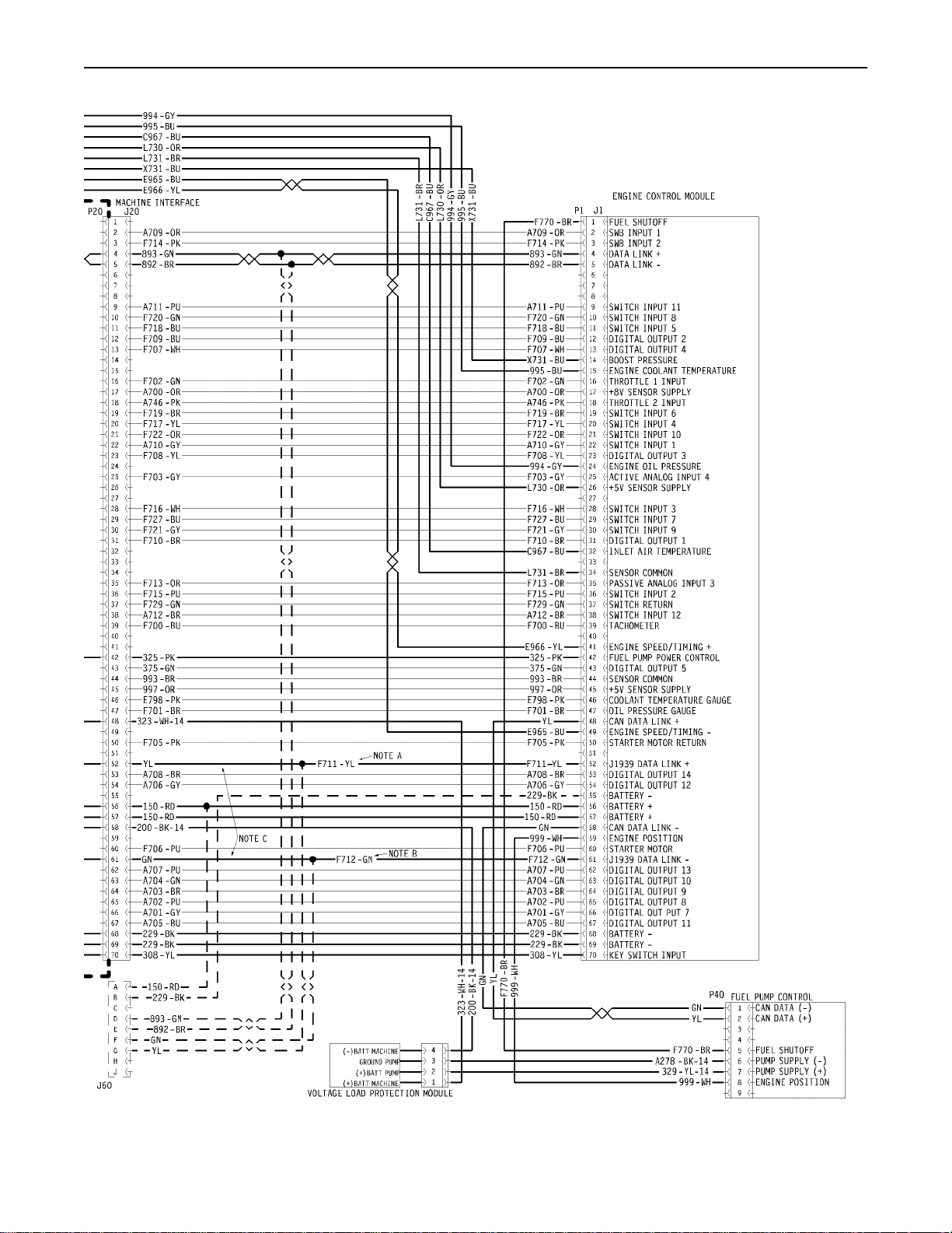
Illustration 12
Schematic for the fuel injection pump and ECM power supply
g00910876
Page 26
27
Troubleshooting Section
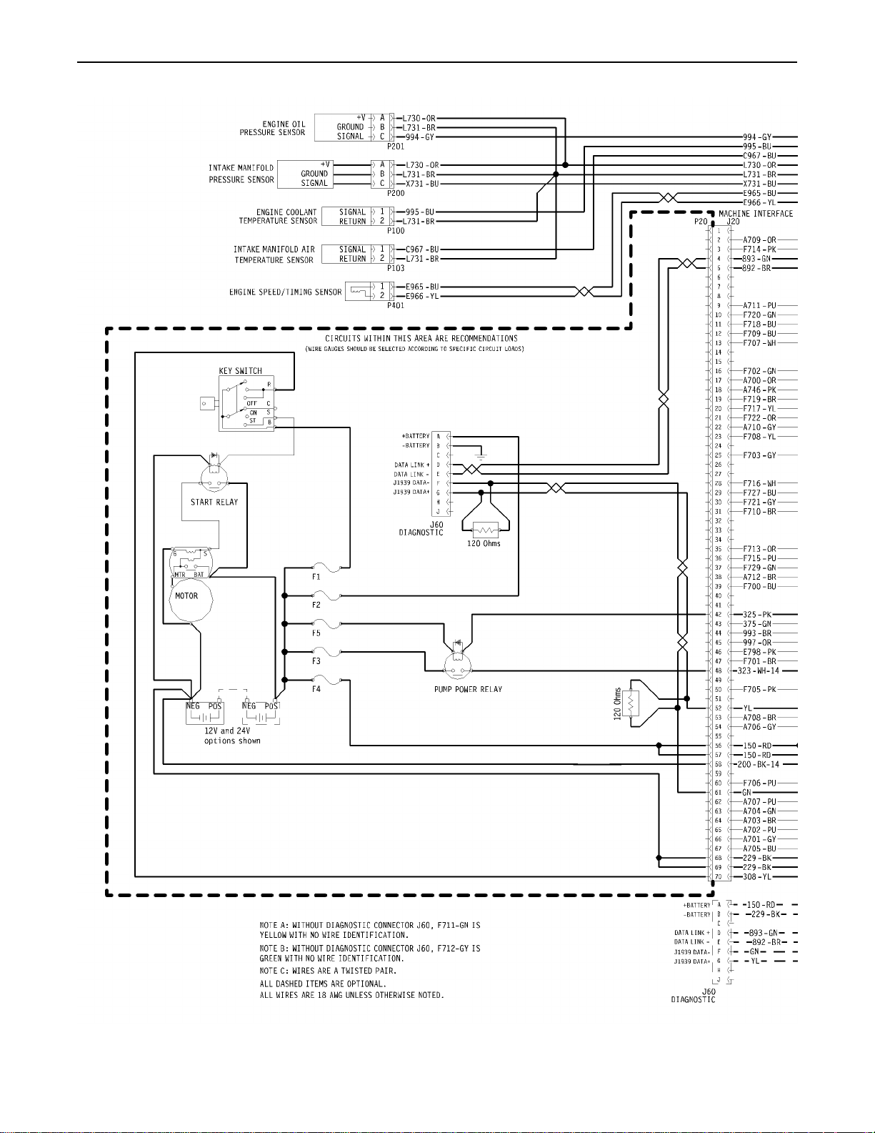
Illustration 13
g00955504
Page 27
28
Troubleshooting Section
Illustration 14
g00955499
Page 28

Note: Each terminal end of the J1939 CAN data
link must be connected with a 120 ohm terminating
resistor.
Note: Digital outputs 7,8,9,10,11,12,13, and 14 are
only suitable for a 12 V system.
Harness Wire Identification
Perkins identifies all wires with eleven solid colors.
The circuit number is stamped on the wire at a
25 mm (1 inch) spacing. Table 11 lists the wire
colors and the color codes.
Ta bl e 1 1
Color Codes for the Harness Wire
Color Code Color Color Code Color
BK
BR Brown BU Blue
RD Red PU Purple
OR Orange GY Gray
YL Yellow WH White
Black GN Green
PK Pink
29
Troubleshooting Section
For example, a wire identification of F702-GN on
the schematic would signify a green wire with the
circuit number F702. F702-GN identifies the power
supply for the 8 V throttle sensor.
Note: Always replace a harness wire with the same
gauge of wire and with the same color code.
Page 29

30
Troubleshooting Section
Programming Parameters
i01798107
Programming Parameters
The electronic service tool can be used to view
certain parameters that can affect the operation of
the engine. The electronic service tool can also be
used to change certain parameters. The parameters
are stored in the Electronic Control Module (ECM).
Some of the parameters are protected from
unauthorized changes by passwords. Parameters
that can be changed have a tattletale number. The
tattletale number shows if a parameter has been
changed.
i01798108
Factory Passwords
Passwords
Note: The old interlock code is required to change
the interlock code on a used ECM. A new interlock
code is also required to change the interlock code
on a used ECM.
The electronic service tool screen for factory
passwords will display the following parameters:
Serial number of the Electronic Control Module
•
(ECM)
Engine serial number
•
Serial number for the electronic service tool
•
Reason Code
•
Total Tattletale number
•
Note: The factory passwords may only be used
for one programming session. A different set of
factory passwords will be required after you exit
the electronic service tool screen. A different set of
passwords will be required to change information
on another electronic service tool screen.
Customer Passwords
Passwords are part of a security system that helps
to prevent unauthorized reprogramming of certain
parameters. Passwords prevent unauthorized
erasing of logged events. Passwords allow the
factory to control access to engine calibration
parameters. Passwords allow the customer to
control access to certain programmable engine
parameters.
Factory Passwords
Factory passwords are required to clear any event
code. Factory passwords are required to change
certain parameters such as Full Load Setting. The
factory passwords restrict changes to authorized
personnel. When the correct factory passwords
have been entered, the changes can then be made.
In order to obtain the proper factory passwords,
certain information must be given to an authorized
Perkins distributor. Since the factory passwords
contain alphabetic characters, the electronic
service tool can be used to perform this function.
In order to obtain the factory passwords, proceed
as if you already have the factory passwords. At
some point, if the factory passwords are actually
needed, the electronic service tool will request the
factory passwords and the electronic service tool
will display the information that is required to obtain
the factory passwords.
Customer Passwords allow the customer to restrict
access to parameters that are programmable by
the customer. The customer passwords cannot be
longer than eight characters. The customer has the
option of entering one or two customer passwords.
Note: If the owner loses the owner’s customer
passwords, the owner will not be able to program
parameters that are protected by customer
passwords. By using factory passwords, one can
read customer passwords. Then use those customer
passwords to program parameters that have been
protected by customer passwords.
i01798110
Flash Programming
Flash Programming – This is a method of
programming or updating the personality module
in an ECM.
The electronic service tool can be utilized to flash
a new personality module into the ECM. The flash
is accomplished by transferring the data from a PC
to the ECM.
Page 30

Flash Programming a Personality
Module
1. Connect the electronic service tool to the service
tool connector.
2. Select “WinFlash” from the “Utilities” menu on the
electronic service tool.
“WinFlash” will try to detect an ECM.
3. When an ECM has been detected, the “ECM
Selector” window will appear. Select the
appropriate ECM that needs to be flashed and
press “Browse”.
The “Flash File Selection” window will appear.
4. The flash files are located on a disk drive and in
a directory. Select the correct disk drive and the
correct directory from “Drives” and “Directories”
on the electronic service tool.
31
Troubleshooting Section
A list of flash files will appear.
5. Select the correct file from the list of flash files.
Read the “File Info” and the “Description” in
order to verify that the correct file is selected.
Select “OK”.
6. Select the “Begin Flash” button in order to
program the personality module.
When the flash is completed, this message will
appear: “Flash Completed Successfully”.
7. Start the engine and check for proper operation.
a. If a diagnostic code of 253-02 Incorrect
ECM Software is generated, program any
parameters that were not in the old personality
module.
b. Access the “Configuration” screen under
the “Service” menu in order to determine
the parameters that require programming.
Look under the “Tattletale” column. All of the
parameters should have a tattletale of 1 or
more. If a parameter has a tattletale of 0,
program that parameter.
“WinFlash” Error Messages
If you receive any error messages during flash
programming, click on the “Cancel” button in order
to stop the process. Access the information about
the “ECM Summary” under the “Information” menu.
Make sure that you are flashing the correct file for
your engine.
Page 31

32
Troubleshooting Section
System Configuration
Parameters
i01798111
System Configuration
Parameters
System Configuration Parameters affect the
emissions of the engine or the power of the engine.
System configuration parameters are programmed
at the factory. Normally, system configuration
parameters would never need to be changed
through the life of the engine. System configuration
parameters must be reprogrammed if an ECM is
replaced. Unless the engine rating has changed,
system configuration parameters do not need to
be reprogrammed when the Personality Module is
replaced. The correct values for these parameters
are stamped on the engine information ratings
plate. The engine information ratings plate is
located on the valve cover or on the air intake
manifold. Factory passwords are required to change
these parameters. The following information is a
description of the system configuration parameters.
“Full Load Setting”
“Full Load Setting” is a number that represents the
adjustment to the fuel system that was made at
the factory in order to fine tune the fuel system.
The correct value for this parameter is stamped
on the engine information ratings plate. If the
ECM is replaced, the “full load setting” must
be reprogrammed in order to prevent a 253-02
diagnostic code from becoming active.
“Full Torque Setting”
“Full Torque Setting” is similar to “Full Load Setting”.
If the ECM is replaced, the full torque setting must
be reprogrammed in order to prevent a 253-02
diagnostic code from becoming active.
When an ECM is replaced this rating interlock code
must match the code that is stored in the ECM. If
the rating interlock code does not match the code
that is stored in the ECM, both of the following
situations will exist:
The engine will not run.
•
The diagnostic code 253-02 (Incorrect ECM
•
Software) will be active.
Note: The flash programming of a new rating
interlock replaces the old rating interlock.
This code does not need to be programmed when
the replacement ECM is from the same engine
rating.
If the ECM is from a different engine rating, then the
following components may need to be changed:
pistons, fuel injectors, and other components.
The engine information ratings plate must also be
changed in order to reflect the new rating.
Some vehicle systems such as the cooling system
or the transmission may also require changes when
the engine is rerated. Please contact the local OEM
dealer for further information.
“Engine Serial Number”
When a new ECM is delivered, the engine serial
number in the ECM is not programmed. The “Engine
Serial Number” should be programmed to match
the engine serial number that is stamped on the
engine information plate.
“ECM Software Release Date”
This parameter is defined by the rating interlock
and this parameter is not programmable. The “ECM
Software Release Date” is used to provide the
version of the software. The Customer parameters
and the software change levels can be monitored
by this date. The date is provided in the month and
the year (NOV99). NOV is the month (November).
99 is the year (1999).
Rating Interlock
The Rating Interlock is a code that prevents the
use of an incorrect power rating and/or emission
rating for a specific engine. Each horsepower rating
and each emission certification has a different
code to all other horsepower ratings and emission
certifications.
Page 32

33
Troubleshooting Section
Troubleshooting without a
Diagnostic Code
i01798099
Alternator Noise
(Noisy Operation)
Note: This is NOT an electronic system problem.
Refer to Testing and Adjusting for information on
determining the cause of this condition.
Probable Causes
Alternator drive belts
•
Alternator drive pulley
•
Alternator bearings
•
Recommended Actions
Alternator Drive Belts
i01798098
Alternator Will Not Charge
(Charging Problem)
Note: This is NOT an electronic system problem.
Probable Causes
Alternator drive belts
•
Charging circuit
•
Regulator
•
Alternator
•
Recommended Actions
Alternator Drive Belts
1. Inspect the condition of the alternator drive belts.
If the alternator drive belts are worn or damaged,
replace the belts. Refer to Disassembly
and Assembly, “Alternator - Remove” and
Disassembly and Assembly, “Alternator - Install”.
1. Inspect the condition of the alternator drive belts.
If the alternator drive belts are worn or damaged,
replace the belts. Refer to Disassembly
and Assembly, “Alternator - Remove” and
Disassembly and Assembly, “Alternator - Install”.
Ensure that the alternator drive belts are in
alignment. Inspect the alternator mounting
bracket for cracks and wear. Repair the mounting
bracket or replace the mounting bracket in order
to ensure that the alternator drive belts and the
alternator drive pulley are in alignment.
2. Check the tension on the alternator drive belts.
Adjust the tension, if necessary. Refer to Testing
and Adjusting, “V-Belt - Test”.
Alternator Drive Pulley
Loosen the nut for the alternator drive pulley and
tighten the nut to the correct torque. Refer to
Specifications, “Alternator and Regulator” for the
correct torque.
Alternator Bearings
Verify that there is excessive play of the shaft in
the alternator and that the alternator bearings are
worn. The alternator is a nonserviceable item.
The alternator must be replaced if the bearings
are worn. Refer to Disassembly and Assembly,
“Alternator - Remove” and Disassembly and
Assembly , “Alternator - Install”.
Check the tension on the alternator drive belts.
Adjust the belt tension if the tension is incorrect.
Refer to Testing and Adjusting, “V-Belt - Test”.
Charging Circuit
Inspect the battery cables, wiring, and connections
in the charging circuit. Clean all connections and
tighten all connections. Replace any faulty parts.
Alternator or Regulator
Verify that the alternator or the regulator is operating
correctly. Refer to Testing and Adjusting, “Alternator
- Test”. The alternator is not a serviceable item. The
alternator must be replaced if the alternator is not
operating correctly.
i01798112
Battery
Note: This is NOT an electronic system problem.
Probable Causes
Faulty battery
•
Auxiliary device drains the battery current.
•
Page 33

34
Troubleshooting Section
Recommended Actions
Faulty Battery
1. Verify that the battery is no longer able to hold a
charge. Refer to Testing and Adjusting, “Battery
- Test”.
2. Replace the battery. Refer to Operation and
Maintenance, “Battery - Replace”.
Auxiliary Device
1. Verify that the auxiliary device drained the battery
by being left in the ON position.
2. Charge the battery.
3. Verify that the battery is able to maintain a
charge.
i01798113
Can Not Reach Top Engine
RPM
Recommended Actions
Diagnostic Codes
Check for active diagnostic codes on the electronic
service tool. Troubleshoot any active codes before
continuing with this procedure.
Fuel Supply
1. Check the fuel pressure. Refer to Systems
Operation, Testing and Adjusting, “Fuel System
Pressure - Test”.
2. Ensure that the fuel system has been primed.
Refer to Systems Operation, Testing and
Adjusting, “Fuel System - Prime”.
3. Check the diesel fuel for contamination. Refer to
Systems Operation, Testing and Adjusting, “Fuel
Quality - Test”.
4. Check for air in the fuel system. Refer to Systems
Operation, Testing and Adjusting, “Air in Fuel Test”.
5. Check that the fuel lines are tight and secured
properly.
Note: If this problem occurs only under load, refer to
Troubleshooting, “Low Power/Poor or No Response
to Throttle”.
Probable Causes
Refer to the logged codes.
•
Fuel supply
•
Air intake and exhaust system
•
Individual malfunctioning cylinders
•
Valve lash
•
Low compression (cylinder pressure)
•
Fuel injection nozzles
•
Turbocharger (if equipped)
•
ECM parameters
•
Throttle signal from the throttle position sensor
•
6. Check for fuel supply lines that are restricted.
7. Check the fuel filters.
8. Visually check the fuel tank for fuel. The fuel
gauge may be faulty.
9. If the engine has a water separator, check for
water in the fuel.
10. Ensure that the fuel supply valve is in the full
OPEN position.
11. If the temperature is below 0
for solidified fuel (wax).
12. If the repairs do not eliminate the problem
proceed to “Air Intake and Exhaust System”.
C (32
F), check
Air Intake and Exhaust System
1. Check the air filter restriction indicator, if
equipped.
2. Ensure that the air filter is clean and serviceable.
3. Check the air intake and the exhaust system for
the following defects:
Blockages
•
Page 34

35
Troubleshooting Section
Restrictions
•
Damage to the air intake and exhaust lines
•
and hoses
4. Make all necessary repairs to the engine.
5. Ensure that the repairs have eliminated the
diagnostic code.
6. If the problem has not been eliminated, proceed
to “Individual Malfunctioning Cylinders”.
Individual Malfunctioning Cylinders
1. With the engine speed at a fast idle, loosen
the high pressure fuel line to the fuel injection
nozzle of number 1 cylinder. Note if there is any
reduction in engine speed. Tighten the high
pressure fuel line to the fuel injection nozzle.
2. Individually repeat this procedure for each fuel
injection nozzle. If there is no reduction in the
engine speed refer to “Check the Turbocharger
(if equipped)”.
3. If all cylinders have been checked and no
problems were detected proceed to “Valve
Lash”.
Valve Lash
1. Check the valve lash and reset the valve lash, if
necessary. Refer to Systems Operation, Testing
and Adjusting, “Engine Valve Lash - Inspect and
Adjust”.
Worn valves
•
Faulty cylinder head gasket
•
Damaged cylinder head
•
Checking the Fuel Injection Nozzles
1. Remove the fuel injection nozzles from the
cylinder head. Refer to Disassembly and
Assembly, “Fuel Injection Nozzle - Remove”.
2. Check the fuel injection nozzles. Refer to Testing
and Adjusting, “Fuel Injection Nozzle - Test”.
3. Ensure that the repairs have eliminated the
problems.
4. If the problem has not been eliminated, proceed
to “Check the Turbocharger (if equipped)”.
Check the Turbocharger (if equipped)
Note: The turbochargers that are equipped on 1100
Series engines are nonserviceable items. If any
mechanical fault exists then the turbocharger must
be replaced.
1. Ensure that the mounting bolts for the
turbocharger are tight.
2. Check that the turbocharger drain is not blocked
or restricted.
3. Check that the turbocharger housing is free of
dirt and debris.
2. If the repair does not eliminate the fault proceed
to “Check for Low Compression”.
Check for Low Compression
1. Remove the fuel injection nozzles and perform a
compression test. Refer to Systems Operation,
Testing and Adjusting, “Compression - Test ”data.
2. Make all necessary repairs to the engine.
3. Ensure that the repairs have eliminated the faults.
4. If the repair does not eliminate the fault refer to
“Checking the Fuel Injection Nozzles”.
Examples of low compression are shown in the
following list:
Mechanical problem
•
Faulty piston rings
•
Worn cylinder bores
•
4. Check the turbocharger for worn bearings. Refer
to Systems Operation, Testing and Adjusting,
“Turbocharger - Inspect”.
5. Check that the turbine blades rotate freely on
the turbocharger. Refer to Systems Operation,
Testing and Adjusting, “Turbocharger - Inspect”.
6. Ensure that the wastegate on the turbocharger is
adjusted correctly. Refer to Systems Operation,
Testing and Adjusting, “Turbocharger - Inspect”.
7. Make all necessary repairs to the engine.
8. Ensure that the repairs have eliminated the faults.
9. If the fault has not been eliminated proceed to
“ECM Parameters”.
ECM Parameters
1. Ensure that the problem is not a programmed
parameter.
Page 35

36
Troubleshooting Section
2. Ensure that the correct mode was selected by
using the electronic service tool.
3. Use the electronic service tool to verify the
correct engine rating for the engine.
4. Use the electronic service tool to verify the
maximum engine speed limit.
5. Use the electronic service tool to reset the
parameters to the OEM specifications.
6. Ensure that the repairs have eliminated the
performance problems.
7. If the repairs have not eliminated the faults
proceed to “Check the Signal for the Throttle
Position Sensor ”.
Check the Signal for the Throttle Position
Sensor
1. Use the electronic service tool and observe the
signal for the throttle position sensor.
2. If the signal is erratic, refer to Troubleshooting,
“Throttle Position Sensor Circuit - Test”.
3. If the engine has a throttle switch refer to
Troubleshooting, “Throttle Switch Circuit - Test”.
i01798114
2. Check for leaks in the oil cooler core. Refer to
Testing and Adjusting, “Cooling System” for the
correct procedure. If a leak is found, install a
new oil cooler core. Refer to Disassembly and
Assembly, “Engine Oil Cooler - Remove” for the
correct procedure. Fit new seals between the oil
cooler and the oil cooler cover.
3. Remove the oil filter element or elements. Fit a
new engine oil filter element or elements. Fill the
crankcase with clean engine oil to the correct
level. Refer to the Operation and Maintenance
Manual, “Engine Oil and Filter - Change” for
more information.
Cylinder Head Gasket
1. Remove the cylinder head. Refer to Disassembly
and Assembly, “Cylinder Head - Remove” for
the correct procedure.
2. Inspect the cylinder head gasket for faults and
any signs of leakage.
3. Check the cylinder liner projection. Refer to
Testing and Adjusting, “Basic Block” for more
information. Correct the cylinder liner projection
if it is incorrect.
4. If all of the cylinder liner projections were correct,
and if there was no obvious signs of a faulty
head gasket proceed to the recommended
actions for the Cylinder Head.
Coolant in Engine Oil
Note: This is NOT an electronic system problem.
Refer to Testing and Adjusting for information on
determining the cause of this condition.
Probable Causes
Engine oil cooler core
•
Cylinder head gasket
•
Cylinder head
•
Cylinder block
•
Recommended Actions
Engine Oil Cooler Core
1. Drain the engine lubricating oil from the engine.
5. If any of the cylinder liner projections were
incorrect, and this had resulted in the failure of
the head gasket, fit a new head gasket.
6. To fit a new cylinder head gasket, refer to
Disassembly and Assembly, “Cylinder Head Install” for the correct procedure.
Cylinder Head
Check the cylinder head for flatness. Refer to
Systems Operation, “Cylinder Head - Inspect” for
the correct procedure.
Check for cracks in the cylinder head. If a crack is
found, repair the cylinder head and/or replace the
cylinder head. Refer to Disassembly and Assembly,
“Cylinder Head - Install” for the correct procedure.
If the cylinder head is flat and if the cylinder head is
not cracked then refer to the recommended actions
for the Cylinder Block.
Page 36

37
Troubleshooting Section
Cylinder Block
Inspect the cylinder block for cracks. If a crack
is found, repair the cylinder block or replace the
cylinder block.
i01798115
Coolant Temperature Is Too
High
Note: This is not an electronic system problem.
Refer to Testing and Adjusting for information on
determining the cause of this condition.
Probable Causes
Radiator fins
•
Coolant level
•
Radiator cap and/or pressure relief valve
•
Combustion gases in the cooling system
•
Engine cooling fan
•
Water temperature regulators
•
Restriction in the coolant system
•
Coolant temperature gauge
•
Coolant pump
•
Excessive load on the system
•
Radiator Cap and/or Pressure Relief
Valve
1. Pressure test the cooling system. Refer to Testing
and Adjusting, “Cooling System” for the correct
procedure.
2. Check operation of the pressure relief valve
and the radiator cap. If necessary, clean the
components and/or replace the components.
3. Check that the seating surfaces of the pressure
relief valve and the radiator cap are clean and
undamaged.
Combustion Gases in the Cooling System
Switch off the engine and allow the engine to cool
to below normal working temperature. Remove
the pressure cap for the coolant system. Start the
engine and inspect the coolant for the presence
of bubbles. If bubbles are present in the coolant,
combustion gases may be entering the cooling
system. Check the cylinder head gasket. Refer
to the recommended action for the cylinder head
gasket within Troubleshooting, “Coolant in Engine
Oil”. Check the cylinder head for flatness. Refer
to the recommended action for checking flatness
of the cylinder head within Systems Operations,
“Cylinder Head - Inspect”. Fit the pressure cap if
there are no bubbles in the coolant.
Water Temperature Regulator
Check the water temperature regulator for correct
operation. Refer to Testing and Adjusting, “Cooling
System” for the proper procedure. If necessary,
replace the water temperature regulator. Refer to
Disassembly and Assembly, “Water Temperature
Regulator - Remove and Install” for more information.
Recommended Actions
Radiator Fins
Check the radiator fins for dirt, debris, and/or
damage. Remove any dirt and/or debris and
straighten any bent fins.
Coolant Level
1. Inspect the coolant level. If necessary, add
coolant.
2. Check the cooling system for leaks. Repair any
leaks immediately.
Restriction in the Coolant System
1. Visually inspect the cooling system for collapsed
hoses and/or other restrictions.
2. Clean the radiator and flush the radiator. Refer to
Testing and Adjusting, “Cooling System”.
Coolant Temperature Gauge
Compare the reading for the coolant temperature
from the electronic service tool to the reading for
the coolant temperature from a mechanical gauge.
Coolant Pump
Inspect the impeller of the coolant pump for
damage and/or erosion. If necessary, repair the
coolant pump or replace the coolant pump.
Page 37

38
Troubleshooting Section
Excessive Load on the System
Reduce the load and verify that the condition does
not reoccur.
i01798116
ECM Will Not Accept Factory
Passwords
Probable Causes
Passwords
•
Serial Numbers
•
Total Tattletale
•
Reason Code
•
Recommended Actions
1. Verify that the correct passwords were entered.
Check every character in each password. Turn
the keyswitch to the OFF position for 30 seconds
and then retry.
2. Verify that the electronic service tool is on the
“Factory Password” screen.
3. Use the electronic service tool to verify that the
following information has been entered correctly:
Electrical connectors
•
Data Link
•
Recommended Actions
1. Connect the electronic service tool to the
service tool connector. If the ECM does not
communicate with the electronic service tool,
refer to Troubleshooting, “Electronic Service Tool
Will Not Communicate with ECM”.
2. Ensure that the following items are
correctly installed and undamaged. Refer
to Troubleshooting, “Electrical Connectors Inspect”.
J1/P1 ECM connector
•
J20/P20 Machine interface connector
•
Wiring to display modules
•
Wiring to other control modules
•
3. Troubleshoot the Data Link for possible problems.
Refer to Troubleshooting, “Data Link Circuit Test”.
i01798118
Electronic Service Tool Will
Not Communicate with ECM
Engine serial number
•
ECM serial number
•
Serial number for the electronic service tool
•
Total tattletale
•
Reason code
•
i01798117
ECM Will Not Communicate
with Other Systems or Display
Modules
Probable Causes
ECM
•
Probable Causes
The electronic service tool is not correctly
•
configured.
The cables to the electronic service tool are not
•
connected correctly.
The electronic service is not functioning.
•
The electrical power supply to the electronic
•
service tool
The engine protection device is disabling the
•
power supply.
The electrical power supply to the ECM
•
The engine harness
•
Battery voltage
•
Page 38

39
Troubleshooting Section
Recommended Actions
Connect the communication adapter of the
electronic service tool to the PC and to the
diagnostic connector. Turn the ignition switch to
the ON position. If the communication adapter for
the electronic service tool activates, and the red
power indicator lamp is ON, proceed to step 3. If
the red power indicator lamp remains OFF proceed
to step 1.
1. Check the battery voltage to the Data Link
Connector. Refer to Troubleshooting, “Data Link
Circuit - Test, Test Step 4”.
2. Change the electronic service tool components.
Refer to Troubleshooting, “Data Link Circuit Test, Test Step 6”.
3. Start the program for the electronic service tool.
If the electronic service tool reports “Connected
and 1 (or more) module detected” then STOP. If
the electronic service tool reports “The interface
hardware is not connected” then proceed to step
4. If the electronic service tool cannot connect to
the ECM then proceed to step 5.
4. Inspect the cable from the PC to the
communication adapter. Verify that the correct
PC port has been used. Inspect the cable from
the electronic service tool to the diagnostic
connector. Change the electronic service tool
components. Refer to Troubleshooting, “Data
Link Circuit - Test, Test Step 6”.
5. Check the battery voltage at the ECM if the
electronic service tool cannot connect to the
ECM. Refer to Troubleshooting, “Data Link Circuit
- Test, Test Step 3”.
Starting motor or starting circuit
•
Valve lash
•
Fuel injection nozzle
•
Air inlet heater starting aid
•
Air intake and exhaust system
•
Low compression (cylinder pressure)
•
Fuel supply
•
Recommended Actions
Diagnostic Codes
Check for active diagnostic codes on the electronic
service tool. Troubleshoot any active codes before
continuing with this procedure.
Visual Checks
1. Visually inspect the engine for the following
faults:
Missing components
•
Damaged components
•
Oil leaks
•
Coolant leaks
•
Fuel leaks
•
Hydraulic leaks
•
6. Connect the electronic service tool directly
to the ECM and follow the test procedure as
Troubleshooting, “Data Link Circuit - Test, Test
Step 5”.
7. Connect the electronic service tool and the ECM
to another battery. Proceed to Troubleshooting,
“Data Link Circuit - Test, Test Step 7”.
i01798119
Engine Cranks but Will Not
Start
Probable Causes
Refer to the logged codes.
•
Crank without injection (if equipped)
•
Check electrical cables for damage. Check
•
that the electrical cables are properly secured.
Check for the proper level of fuel, oil, coolant,
•
and hydraulic fluids
2. Try to start the engine. If the engine does
not start, verify that the crankshaft is rotating.
Use a suitable hand tool in order to rotate the
crankshaft.
3. If the crankshaft rotates freely proceed to
“Starting Motor Solenoid or Starting Circuit”.
4. If the crankshaft does not rotate freely, check the
engine for the following problems:
Seized piston
•
Defects in the drive gears
•
Fluid in the cylinder bores
•
Page 39

40
Troubleshooting Section
Improper timing of valves
•
Crank Without Injection (If Equipped)
1. Check if the crank without injection plug is
connected.
2. If the crank without injection plug has been
connected, connect the normal running plug.
3. Check if the engine will start.
4. If the repairs do not eliminate the problem refer
to Troubleshooting, “Crank without Inject Circuit
- Test”.
Starting Motor Solenoid or Starting
Circuit
1. Turn the keyswitch to the OFF position.
2. Check the positive battery and negative battery
connections to the ECM.
3. Perform a pull test on positive battery wires and
negative battery wires. Refer to Troubleshooting,
“Electrical Connectors - Inspect”.
Fuel Injection Nozzles
1. Remove the fuel injection nozzles from the
cylinder head. Refer to Disassembly and
Assembly, “Fuel Injection Nozzle - Remove”.
2. Check the fuel injection nozzles. Refer to
Systems Operation, Testing and Adjusting, “Fuel
Injection Nozzle - Test”.
3. If the repairs do not eliminate the problem
proceed to “Air Inlet Heater Starting Aid”.
Air Inlet Heater Starting Aid
1. Check that the air inlet heater is receiving both an
electrical current and a supply of fuel. Check the
operation of the air inlet heater starting aid. Refer
to Systems Operation, “Air Inlet Heater - Test”.
2. If the repairs do not eliminate the problem
proceed to “Air Intake and Exhaust System”.
Air Intake and Exhaust System
1. Check the air filter restriction indicator, if
equipped.
4. Check the negative battery connection on the
ground stud.
5. Check the connections of starting motor
terminals.
6. Check the starting motor solenoid.
7. Remove the starting motor and check the starter
motor for proper operation. Check the pinion of
the starting motor and check the flywheel ring
gear.
8. Check the operation of the starting switch. Refer
to Troubleshooting, “Electrical power Supply
Circuit - Test”.
Valve lash
1. Check the valve lash and reset the valve lash
if it is necessary. Refer to Systems Operation,
Testing and Adjusting, “Engine Valve Lash Inspect and Adjust”.
Ensure that the repairs have eliminated the active
diagnostic codes before attempting to restart the
engine.
2. Ensure that the air filter is clean and serviceable.
3. Check the air intake and exhaust systems for
the following defects:
Blockages
•
Restrictions
•
Damage to lines or hoses
•
4. Repair any defects before attempting to restart
the engine.
5. If the engine will not start proceed to “Low
Compression”.
Low Compression
1. Remove the fuel nozzles and perform a
compression test. Refer to Systems Operations,
Testing and Adjusting, “Compression - Test ”data.
Examples of low compression are shown in the
following list:
Outside temperatures are too cold.
•
If the engine will not start proceed to “Air Intake
and Exhaust System”.
Mechanical problem
•
Faulty piston rings
•
Page 40

41
Troubleshooting Section
Worn cylinder bores
•
Worn valves
•
Faulty cylinder head gasket
•
Damaged cylinder head
•
2. Make all necessary repairs to the engine.
3. Ensure that the repairs have eliminated the active
diagnostic code.
4. If the engine will not start proceed to “Fuel
Supply”.
Fuel Supply
1. Check the fuel pressure. Refer to Systems
Operation, Testing and Adjusting, “Fuel System
Pressure - Test”.
2. Ensure that the fuel system has been primed.
Refer to Systems Operation, Testing and
Adjusting, “Fuel System - Prime”.
3. Check the diesel fuel for contamination. Refer to
Systems Operation, Testing and Adjusting, “Fuel
Quality - Test”.
Leaks in air intake system
•
Low oil pressure
•
Recommended Actions
Dirt in Engine Oil
1. Drain the oil from the crankcase and refill the
crankcase with clean engine oil. Install new
engine oil filters. Refer to the Operation and
Maintenance Manual for more information.
2. Check the oil filter bypass valve for a weak
spring or a broken spring. If the spring is weak or
broken, replace the spring. Refer to Disassembly
and Assembly, “Engine Oil Filter Base” for more
information.
Leaks in Air Intake System
A leak in the air intake system may allow unfiltered
air into the engine. Inspect the air intake system
for leaks. Inspect all of the gaskets and the
connections. Repair any leaks. Refer to Testing and
Adjusting, “Air Intake System” for more information.
Low Oil Pressure
4. Check for air in the fuel system. Refer to Systems
Operation, Testing and Adjusting, “Air in Fuel Test”.
5. Check that the fuel lines are tight and secured
properly.
6. Check for fuel supply lines that are restricted.
7. Check the fuel filters.
8. Visually check the fuel tank for fuel. The fuel
gauge may be faulty.
9. If the engine has a water separator, check for
water in the fuel.
10. Ensure that the fuel supply valve (if equipped) is
in the full OPEN position.
11. If the temperature is below 0
for solidified fuel (wax).
C (32F), check
i01798120
Engine Has Early Wear
Refer to Troubleshooting, “Low Engine Oil Pressure”
for the testing procedure. Repair any identified
faults.
i01798121
Engine Misfires, Runs Rough
or Is Unstable
The probable root causes are listed in order below:
Note: If the problem is intermittent and the problem
cannot be duplicated, refer to Troubleshooting,
“Intermittent Low Power or Power Cutout”.
Note: If the problem only occurs under certain
conditions, test the engine under those conditions.
Examples of certain conditions are high rpm,
full load and engine operating temperature.
Troubleshooting the symptoms under other
conditions can give misleading results.
Probable Causes
Probable Causes
Dirt in engine oil
•
Refer to the logged codes.
•
Fuel supply
•
Air intake and exhaust system
•
Page 41

42
Troubleshooting Section
Individual malfunctioning cylinder
•
Valve lash
•
Low compression (cylinder pressure)
•
Fuel injection nozzles
•
Air inlet heater starting aid
•
Engine speed/timing sensors
•
Throttle position sensor
•
Fuel injection pump
•
Recommended Actions
Logged Codes
Check for active diagnostic codes on the electronic
service tool. Troubleshoot any active codes before
continuing with this procedure.
Fuel Supply
1. Check the fuel pressure. Refer to Systems
Operation, Testing and Adjusting, “Fuel System
Pressure - Test”.
2. Ensure that the fuel system has been primed.
Refer to Systems Operation, Testing and
Adjusting, “Fuel System - Prime”.
3. Check the diesel fuel for contamination. Refer to
Systems Operation, Testing and Adjusting, “Fuel
Quality - Test”.
12. If the repairs do not eliminate the problem
proceed to “Air Intake and Exhaust System”.
Air Intake and Exhaust System
1. Check the air filter restriction indicator, if
equipped.
2. Ensure that the air filter is clean and serviceable.
3. Check the air intake and exhaust systems for
the following defects:
Blockages
•
Restrictions
•
Damage to lines or hoses
•
4. If the repairs do not eliminate the problem
proceed to “Individual Malfunctioning Cylinders”.
Individual Malfunctioning Cylinders
1. With the engine speed at a fast idle, loosen
the high pressure fuel line to the fuel injection
nozzle of number 1 cylinder. Note if there is any
reduction in engine speed. Tighten the high
pressure fuel line to the fuel injection nozzle.
2. Individually repeat this procedure for each fuel
injection nozzle. If there is not a reduction in the
engine speed proceed to “Check the Air Inlet
Heater Starting Aid”.
3. If there is a reduction in engine speed proceed
to “Valve Lash”.
4. Check for air in the fuel system. Refer to Systems
Operation, Testing and Adjusting, “Air in Fuel Test”.
5. Check that the fuel lines are tight and secured
properly.
6. Check for fuel supply lines that are restricted.
7. Check the fuel filters.
8. Visually check the fuel tank for fuel. The fuel
gauge may be faulty.
9. If the engine has a water separator, check for
water in the fuel.
10. Ensure that the fuel supply valve (if equipped) is
in the full OPEN position.
11. If the temperature is below 0
for solidified fuel (wax).
C (32F), check
Valve lash
1. Check the valve lash and reset the valve lash
if it is necessary. Refer to Systems Operation,
Testing and Adjusting, “Engine Valve Lash Inspect and Adjust”.
2. If the repair does not eliminate the fault proceed
to “Check for Low Compression”.
Check for Low Compression
Examples of low compression are shown on the
following list:
Mechanical problems
•
Faulty piston rings
•
Worn cylinder bores
•
Worn valves
•
Page 42

43
Troubleshooting Section
Faulty cylinder head gasket
•
Damaged cylinder head
•
1. Remove the fuel injection nozzles and perform a
compression test. Refer to Systems Operations,
Testing and Adjusting, “Compression - Test ”
data.
2. Make all necessary repairs to the engine.
3. If the repair does not eliminate the fault proceed
to “Check the Fuel Injection Nozzles”.
Check the Fuel Injection Nozzles
1. Remove the fuel injection nozzles from the
cylinder head. Refer to Disassembly and
Assembly, “Fuel Injection Nozzle - Remove”.
2. Check the fuel injection nozzles. Refer to
Systems Operation, Testing and Adjusting, “Fuel
Injection Nozzle - Test”.
3. If the repairs do not eliminate the fault proceed
to “Check the Air Inlet Heater Starting Aid”.
Check the Air Inlet Heater Starting Aid
1. Check for proper operation of the air inlet heater
starting aid. Refer to Systems Operation, Testing
and Adjusting, “Electrical System”.
2. If the repairs do not eliminate the fault refer to
“Check the Engine Speed/Timing Sensors”.
4. If a fault with the engine speed/timing sensor
is suspected refer to Troubleshooting, “Engine
Speed/Timing Circuit - Test”.
5. If a fault with the engine speed/timing sensor is
not suspected proceed to “Check the Signal for
the Throttle Demand Sensor”.
Check the Signal for the Throttle Position
Sensor
1. Use the electronic service tool and observe the
signal for the throttle position sensor.
2. If the signal is erratic, refer to Troubleshooting,
“Throttle Position Sensor Circuit - Test”.
3. If the engine has a 10 position throttle switch
refer to Troubleshooting, “Throttle Switch Circuit
- Test”.
4. If the repairs do not eliminate the fault proceed
to “Check the Fuel injection Pump”.
Check the Fuel Injection Pump
Note: The fuel injection pumps that are installed
by the factory on the 1100 series engines are
nonserviceable items. If any mechanical fault or any
electrical fault occurs within the fuel injection pump
then the fuel injection pump must be replaced.
1. Use the electronic service tool to select the
correct screen display. Refer to Troubleshooting,
“Troubleshooting with a Diagnostic Code”.
Check the Engine Speed/Timing Sensors
Note: There are two engine speed/timing sensors.
One sensor is positioned in the cylinder block in
order to sense the crankshaft position and the
crankshaft speed. The other sensor is in the fuel
injection pump in order to sense the pump’s internal
timing wheel and speed. The sensor in the fuel
injection pump is not serviceable. If the sensor
in the fuel injection pump is faulty then the fuel
injection pump should be replaced.
1. Ensure that the engine speed/timing sensor is
installed correctly to the cylinder block.
2. Ensure that the connectors and cables for the
engine speed/timing sensors are connected
correctly.
3. Check the wiring harness in order to ensure
that the cables to the sensors are not too tight.
This could cause an intermittent problem due
to vibration.
2. If the problem is not eliminated, check for active
diagnostic fault codes.
3. Refer to Troubleshooting, “Fuel Injection Pump
Circuit - Test”.
i01798122
Engine Oil in Cooling System
Note: This is NOT an electronic system problem.
Refer to Testing and Adjusting for information on
determining the cause of this condition.
Probable Causes
Engine oil cooler core
•
Cylinder head gasket
•
Cylinder head
•
Page 43

44
Troubleshooting Section
Recommended Actions
Engine Oil Cooler Core
1. Drain the coolant from the engine and the
radiator. Drain the lubricating engine oil from the
engine oil cooler. Refer to the Operation and
Maintenance Manual for more information.
2. Inspect the engine oil cooler core for leaks. Refer
to Testing and Adjusting, “Cooling System” for
the correct procedure. If a leak is found, replace
the oil cooler core. Refer to Disassembly and
Assembly, “Engine Oil Cooler Core - Remove”.
Fit new seals between the oil cooler and the oil
cooler cover.
3. Refill the crankcase with clean engine oil to
the correct level. Refer to the Operation and
Maintenance Manual for more information.
Cylinder Head Gasket
1. Remove the cylinder head. Refer to Disassembly
and Assembly, “Cylinder Head - Remove” for
the correct procedure.
Thoroughly flush the coolant system in order to
remove all traces of the engine lubricating oil
from the coolant system. Fill the coolant system
with coolant. Refer to Operation and Maintenance
Manual for more information.
i01798123
Engine Speed Does Not
Change
Note: Use this procedure only if the engine speed
does not change.
Probable Causes
Refer to logged codes.
•
Throttle switch
•
Throttle position sensor
•
Engine speed/timing sensor
•
2. Inspect the cylinder head gasket for faults and
any signs of leakage.
3. Check the cylinder liner projection. Refer to
Testing and Adjusting, “Basic Block” for the
correct procedure.
4. If all of the cylinder liner projections were correct,
and if there was no obvious signs of a faulty
head gasket proceed to the recommended
actions for the Cylinder Head.
5. If any of the cylinder liner projections were
incorrect, and this had resulted in the failure of
the head gasket, fit a new head gasket. Refer to
Disassembly and Assembly, “Cylinder Head Install” for the correct procedure.
Cylinder Head
1. Check the cylinder head for flatness. Refer to
Systems Operation, “Cylinder Head - Inspect” for
the correct procedure.
2. Check the cylinder head for cracks. If a crack is
found, repair the cylinder head and/or replace
the cylinder head. If the cylinder head is not
cracked and the head is flat, fit the head. Refer
to Disassembly and Assembly, “Cylinder Head Install” for the correct procedure.
Recommended Repairs
Diagnostic Codes
Check for active diagnostic codes on the electronic
service tool. Troubleshoot any active codes before
continuing with this procedure.
If a problem with the throttle switch is suspected
refer to Troubleshooting, “Throttle Switch Circuit Test”.
Refer to Troubleshooting, “Throttle Position Sensor
Circuit - Test” if any of the following diagnostic
codes are active.
91-08 Throttle Position Sensor Abnormal
•
774-08 Sec Throttle Position Signal Abnormal
•
41-03 8 Volt Sensor Power Supply Voltage more
•
than normal
41-04 8 Volt Sensor Power Supply Volltage less
•
than normal
Refer to Troubleshooting, “Engine Speed/Timing
Sensor Circuit - Test” if any of the following
diagnostic codes are active.
320-02 Speed/Timing Sensor intermittent loss of
•
signal
Page 44

45
Troubleshooting Section
320-11 Speed/Timing Sensor loss of signal
•
If there are no active diagnostic codes refer to
the Troubleshooting Manual for your machine
application.
i01798124
Engine Stalls at Low RPM
Probable Causes
Refer to logged codes.
•
Faulty fuel injection nozzles
•
Fuel supply
•
Accessory equipment
•
Power mode control (if equipped)
•
Recommended Actions
5. Check that the fuel lines are tight and secured
properly.
6. Check for fuel supply lines that are restricted.
7. Check the fuel filters.
8. Visually check the fuel tank for fuel. The fuel
gauge may be faulty.
9. If the engine has a water separator, check for
water in the fuel.
10. Ensure that the fuel supply valve (if equipped) is
in the full OPEN position.
11. If the temperature is below 0
for solidified fuel (wax).
NOTICE
Do not crank the engine continuously for more than
30 seconds. Allow the starting motor to cool for two
minutes before cranking the engine again.
C (32
F), check
Accessory Equipment
Diagnostic Codes
Check for active diagnostic codes on the Electronic
Service Tool. Troubleshoot any active codes before
continuing with this procedure.
Fuel Injection Nozzles
1. Check for correct installation of fuel injection
nozzles. Refer to Disassembly and Assembly,
“Fuel Injection Nozzle - Install”.
2. Check for proper operation of the fuel injection
nozzle. Refer to Systems Operation, Testing and
Adjusting, “Fuel Injection Nozzle - Test”.
Fuel Supply
1. Check the fuel pressure. Refer to Systems
Operation, Testing and Adjusting, “Fuel System
Pressure - Test”.
2. Ensure that the fuel system has been primed.
Refer to Systems Operation, Testing and
Adjusting, “Fuel System - Prime”.
Check all accessory equipment for problems that
may create excessive load on the engine. Repair
any damaged components or replace any damaged
components.
Power Mode Control (If Equipped)
1. Check the Data Link. Refer to Troubleshooting, “
Data Link Circuit - Test”.
2. Check the engine wiring harness for defects.
Refer to Troubleshooting, “Electricial Connectors
- Inspect”.
3. If there are no active diagnostic codes refer
to the Troubleshooting Manual for your engine
application.
i01798125
Engine Vibration
Note: This is NOT an electronic system problem.
3. Check the diesel fuel for contamination. Refer to
Systems Operation, Testing and Adjusting, “Fuel
Quality - Test”.
4. Check for air in the fuel system. Refer to Systems
Operation, Testing and Adjusting, “Air in Fuel Test”.
Refer to Testing and Adjusting for information on
determining the cause of this condition.
Probable Causes
Engine supports
•
Malfunctioning individual cylinder
•
Page 45

46
Troubleshooting Section
Valve lash
•
Compression (cylinder pressure)
•
Fuel injection nozzles
•
Turbocharger (if equipped)
•
Recommended Actions
Engine Supports
1. Start the engine and run the engine through the
speed range. Check for any of the following
conditions:
Loose engine supports
•
Loose mounting brackets or broken mounting
•
brackets
Loose bolts
•
Omitted bolts
•
2. Make all necessary repairs. Ensure that
the repairs have eliminated the problem.
If the vibration is still present proceed to
“Malfunctioning Individual Cylinder”.
Malfunctioning Individual Cylinder
1. With the engine speed at a fast idle, loosen
the high pressure fuel line to the fuel injection
nozzle of number 1 cylinder. Note if there is any
reduction in engine speed. Tighten the high
pressure fuel line to the fuel injection nozzle.
2. Individually repeat this procedure for each fuel
injection nozzle. If there is no reduction in the
engine speed proceed to “Check The Fuel
Injection Nozzles”.
3. If there is a reduction in engine speed proceed
to “Valve Lash”.
Valve Lash
1. Ensure that the valve lash is correct. Reset the
valve lash if it is not correct. Refer to Systems
Operation, Testing and Adjusting, “Engine Valve
Lash - Inspect and Adjust”.
2. If the repair does not eliminate the fault proceed
to “Check for Low Compression (cylinder
pressure)”.
Check for Low Compression (cylinder
pressure)
1. Remove the fuel injection nozzles from the
cylinder head. Refer to Disassembly and
Assembly, “Fuel Injection Nozzle - Remove”.
2. Check the fuel injection nozzles. Refer to Testing
and Adjusting, “Fuel Injection Nozzle - Test”.
3. Perform a compression test on each cylinder.
Refer to Systems Operation, Testing and
Adjusting, “Compression - Test”.
4. Ensure that the repairs have eliminated the
problems.
5. If the problem has not been eliminated, proceed
to “Check the Fuel Injection Nozzles”.
Check the Fuel Injection Nozzles
1. Remove the fuel injection nozzles from the
cylinder head. Refer to Disassembly and
Assembly, “Fuel Injection Nozzle - Remove”.
2. Check the fuel injection nozzles. Refer to Testing
and Adjusting, “Fuel Injection Nozzle - Test”.
3. Ensure that the repairs have eliminated the
problems.
4. If the problem has not been eliminated, proceed
to “Turbocharger (if equipped)”.
Turbocharger (if equipped)
Note: The turbochargers that are equipped on 1100
Series engines are nonserviceable items. If any
mechanical fault exists then the turbocharger must
be replaced.
1. Ensure that the mounting bolts for the
turbocharger are tight.
2. Check that the turbocharger drain is not blocked
or restricted.
3. Check that the turbocharger housing is free of
dirt and debris.
4. Check the turbocharger for worn bearings. Refer
to Systems Operation, Testing and Adjusting,
“Turbocharger - Inspect”. The turbochargers that
are equipped on 1100 Series engines are not
serviceable. If any mechanical fault exists then
the turbocharger must be replaced.
Page 46

47
Troubleshooting Section
5. Check that the turbine blades of the turbocharger
rotate freely. Refer to Systems Operation, Testing
and Adjusting, “Turbocharger - Inspect”.
6. Ensure that the wastegate on the turbocharger is
adjusted correctly. Refer to Systems Operation,
Testing and Adjusting, “Turbocharger - Inspect”.
The adjustment of the wastegate is set at the
factory. If the adjustment of the wastegate
is incorrect then the turbocharger must be
replaced.
7. Make all necessary repairs to the engine.
8. Ensure that the repairs have eliminated the faults.
i01798126
Engine Will Not Crank
Probable Causes
Machine security system
•
6. If there are no active diagnostic codes refer to
the Troubleshooting Manual for your machine
application.
Battery Cables and/or Batteries
1. Inspect the main power switch, battery posts,
and battery cables for loose connections and
corrosion. If the battery cables are corroded,
remove the battery cables and clean the battery
cables. Clean the battery posts. Replace the
cables. Tighten any loose connections.
2. Inspect the batteries.
a. Charge the batteries.
b. Load test the batteries.
Starting Motor Solenoid or Starting
Circuit
1. Test the operation of the starting motor solenoid.
Refer to Systems Operation/Testing and
Adjusting, “Starting System”.
Battery cables and/or batteries
•
Starting motor solenoid or starting circuit
•
Starting motor and/or flywheel ring gear
•
Electrical power supply
•
Internal engine problem
•
Recommended Repairs
Machine Security System
1. Verify that the correct keyswitch is being used.
Turn the keyswitch to the ON position.
2. Use the electronic service tool in order to check
if the 1639-09 Machine Security System is active.
Verify that the lamp for the machine security
system is on.
3. If the 1639-09 diagnostic code is active the
machine security system is armed. Deactivate
the machine security system and try to start the
engine.
2. Check the wiring to the starting motor solenoid.
Starting Motor and/or Flywheel Ring Gear
1. Test the operation of the starting motor. Check
the wiring for the starting motor. Refer to System
Operation, “System Starting”.
2. Inspect the starter motor pinion and the flywheel
ring gear for damage.
Electrical Power Supply
Check the electrical power supply. Refer to
Troubleshooting, “Electrical Power Supply Circuit Test”.
Internal Engine Problem
1. Disassemble the engine. Refer to Disassembly
and Assembly.
2. Inspect the internal components for the following
conditions:
Seizure
•
4. If the engine will not start use the electronic
service tool to check for logged diagnostic
codes.
5. Make repairs for all diagnostic codes. Ensure
that the repair has eliminated the problem.
Broken components
•
Bent components
•
Page 47

48
Troubleshooting Section
i01798127
Excessive Black Smoke
Probable Causes
Air intake system or exhaust system
•
Individual malfunctioning cylinder
•
Valve lash
•
Low compression (cylinder pressure)
•
Fuel injection nozzles
•
Turbocharger (if equipped)
•
Broken 5 volt supply wire to the pressure sensor
•
in the intake manifold
ECM software
•
Recommended Actions
Air Intake System or Exhaust System
1. Check the air filter restriction indicator, if
equipped.
2. Individually repeat this procedure for each fuel
injection nozzle. If there is no reduction in the
engine speed proceed to “Checking the Fuel
Injection Nozzles”.
3. If there is a reduction in engine speed proceed
to “Valve Lash”.
Valve Lash
Ensure that the valve lash is correct. Reset the
valve lash if it is not correct. Refer to Testing and
Adjusting, “Engine Valve Lash - Inspect/Adjust”.
If the repair does not eliminate the fault proceed to
“Low Compression (cylinder pressure)”.
Low Compression (cylinder pressure)
Examples of low compression are shown in the
following list:
Mechanical problem
•
Faulty piston rings
•
Worn cylinder bores
•
Worn valves
•
Faulty cylinder head gasket
•
2. Ensure that the air filter is clean and serviceable.
3. Check the air intake and the exhaust system for
the following defects:
Blockages
•
Restrictions
•
Damage to the air intake and exhaust lines
•
and hoses
4. Make all necessary repairs to the engine.
5. If the problem has not been eliminated, proceed
to “Individual Malfunctioning Cylinder”.
Individual Malfunctioning Cylinder
1. With the engine speed at a fast idle, loosen
the high pressure fuel line to the fuel injection
nozzle of number 1 cylinder. Note if there is any
reduction in engine speed. Tighten the high
pressure fuel line to the fuel injection nozzle.
Damaged cylinder head
•
1. Remove the fuel injection nozzles and perform a
compression test. Refer to Systems Operation,
Testing and Adjusting, “Compression - Test ”data.
2. Make all necessary repairs to the engine.
3. Ensure that the repairs have eliminated the faults.
4. If the repair does not eliminate the fault proceed
to “Checking the Fuel Injection Nozzles”.
Checking the Fuel Injection Nozzles
1. Remove the fuel injection nozzles from the
cylinder head. Refer to Disassembly and
Assembly, “Fuel Injection Nozzle - Remove”.
2. Check the fuel injection nozzles. Refer to Testing
and Adjusting, “Fuel Injection Nozzle - Test”.
3. Ensure that the repairs have eliminated the
problems.
4. If the problem has not been eliminated, proceed
to “Check the Turbocharger (if equipped)”.
Page 48

49
Troubleshooting Section
Check the Turbocharger (if equipped)
Note: The turbochargers that are equipped on 1100
Series engines are nonserviceable items. If any
mechanical fault exists then the turbocharger must
be replaced.
1. Ensure that the mounting bolts for the
turbocharger are tight.
2. Check that the turbocharger drain is not blocked
or restricted.
3. Check that the turbocharger housing is free of
dirt and debris.
4. Check the turbocharger for worn bearings. Refer
to Systems Operation, Testing and Adjusting,
“Turbocharger - Inspect”. The turbochargers that
are equipped on 1100 Series engines are not
serviceable. If any mechanical fault exists then
the turbocharger must be replaced.
5. Check that the turbine blades rotate freely on
the turbocharger. Refer to Systems Operation,
Testing and Adjusting, “Turbocharger - Inspect”.
6. Ensure that the wastegate on the turbocharger is
adjusted correctly. Refer to Systems Operation,
Testing and Adjusting, “Turbocharger - Inspect”.
The adjustment of the wastegate is set by
the factory. If the adjustment of the wastegate
is incorrect then the turbocharger must be
replaced.
7. Make all necessary repairs to the engine.
2. Use the electronic service tool to verify any
active diagnostic codes.
3. If diagnostic codes are present, the ECM must
be programmed with the correct information.
i01798128
Excessive Engine Oil
Consumption
Probable Causes
Oil level
•
Engine crankcase breather
•
Engine oil temperature
•
Air intake and exhaust system
•
Turbocharger (if equipped)
•
Low compression (cylinder pressure)
•
Recommended Actions
Oil Level
Remove excess oil. Locate the source of the
excess fluid. Repair the leaks that are causing the
problems. Recheck all fluid levels.
8. Ensure that the repairs have eliminated the faults.
9. If the repairs have not eliminated the fault
proceed to “Broken 5 volt supply wire”.
Broken 5 volt Supply Wire
1. Check the 5 volt supply for the intake manifold
pressure sensor. Refer to Troubleshooting, “5 volt
Pressue Sensor Supply Circuit - Test”.
2. If the repairs have not eliminated the fault
proceed to “Verifying the ECM Software”.
Verifying the ECM Software
1. Connect the electronic service tool to the
diagnostic connector and check for the following
conditions:
Check for the correct engine serial number
•
Check for the correct arrangement number
•
Check for the correct software
•
Engine Crankcase Breather
1. Check the engine crankcase breather (if
equipped) for blockage or restrictions.
2. Repair all defects. Verify that the repair has
eliminated the problem.
Air Intake and Exhaust System
1. Check the air filter restriction indicator, if
equipped.
2. Ensure that the air filter is clean and serviceable.
3. Check the air intake and the exhaust system for
the following defects:
Blockages
•
Restrictions
•
Damage to the air intake and exhaust lines
•
and hoses
Page 49

50
Troubleshooting Section
4. Make all necessary repairs to the engine.
5. Ensure that the repairs have eliminated the
diagnostic code.
Turbocharger (if equipped)
Note: The turbochargers that are equipped on
1100 Series engines are nonserviceable. If any
mechanical fault exists then the turbocharger must
be replaced.
1. Ensure that the mounting bolts for the
turbocharger are tight.
2. Check that the turbocharger drain is not blocked
or restricted.
3. Check that the turbocharger housing is free of
dirt and debris.
4. Check the turbocharger for worn bearings. Refer
to Systems Operation, Testing and Adjusting,
“Turbocharger - Inspect”. The turbochargers that
are equipped on 1100 series engines are not
serviceable. If any mechanical fault exists then
the turbocharger should be replaced.
5. Check that the turbine blades rotate freely on
the turbocharger. Refer to Systems Operation,
Testing and Adjusting, “Turbocharger - Inspect”.
6. Ensure that the wastegate on the turbocharger is
adjusted correctly. Refer to Systems Operation,
Testing and Adjusting, “Turbocharger - Inspect”.
The adjustment of the wastegate is set at the
factory. If the adjustment of the wastegate
is incorrect then the turbocharger must be
replaced.
7. Make all necessary repairs to the engine.
8. Ensure that the repairs have eliminated the faults.
Mechanical problem
•
Faulty piston rings
•
Worn cylinder bores
•
Worn valves
•
Faulty cylinder head gasket
•
Damaged cylinder head
•
4. Inspect the internal engine components. Replace
any worn components.
i01798129
Excessive Valve Lash
Note: This is NOT an electronic system problem.
Refer to Testing and Adjusting for information on
determining the cause of this condition.
Probable Causes
Lubrication
•
Valve lash
•
Valve train components
•
Recommended Actions
Lubrication
1. Remove the valve mechanism covers. Refer to
Disassembly and Assembly, “Valve Mechanism
Cover - Remove and Install” for the correct
procedure.
Low Compression (cylinder pressure)
1. Verify that the valve lash is correct. Refer
to Systems Operation, “Engine Valve Lash Inspect/Adjust”.
1. Remove the fuel injection nozzles and perform a
compression test. Refer to Systems Operation,
Testing and Adjusting, “Compression - Test ”data.
2. Make all necessary repairs to the engine.
3. Ensure that the repairs have eliminated the faults.
Examples of low compression are shown in the
following list:
2. Check the lubrication in the valve compartment.
Ensure that there is adequate engine oil flow in
the valve compartment. The passages for the
engine oil must be clean.
Valve Lash
Adjust the valve lash of the engine. Refer to Testing
and Adjusting, “Air Intake and Exhaust System” for
the correct procedure.
Valve Train Components
1. Inspect the following components of the valve
train:
Page 50

51
Troubleshooting Section
Rocker arms
•
Pushrods
•
Valve lifters
•
Camshaft
•
Valve stems
•
Rocker shafts
•
2. Check the components for the following
conditions: abnormal wear, excessive wear,
straightness, and cleanliness. If necessary, use
new parts for replacement.
Note: If the camshaft is replaced, new valve lifters
must also be used.
3. Adjust the valve lash of the engine. Refer to
Testing and Adjusting, “Engine Valve Lash Inspect/Adjust” for the correct procedure.
i01798130
Excessive White Smoke
Note: Some white smoke may be present during
cold start-up conditions when the engine is
operating normally. If the white smoke persists,
there may be a problem.
Probable Causes
Fuel supply
•
Individual malfunctioning cylinder
•
2. Ensure that the fuel system has been primed.
Refer to Systems Operation, Testing and
Adjusting, “Fuel System - Prime”.
3. Check the diesel fuel for contamination. Refer to
Systems Operation, Testing and Adjusting, “Fuel
Quality - Test”.
4. Check for air in the fuel system. Refer to Systems
Operation, Testing and Adjusting, “Air in Fuel Test”.
5. Check that the fuel lines are tight and secured
properly.
6. Check for fuel supply lines that are restricted.
7. Check the fuel filters.
8. Visually check the fuel tank for fuel. The fuel
gauge may be faulty.
9. If the engine has a water separator, check for
water in the fuel.
10. Ensure that the fuel supply valve (if equipped) is
in the full OPEN position.
11. If the temperature is below 0
for solidified fuel (wax).
C (32
F), check
Individual Malfunctioning Cylinder
1. With the engine speed at a fast idle, loosen
the high pressure fuel line to the fuel injection
nozzle of number 1 cylinder. Note if there is any
reduction in engine speed. Tighten the high
pressure fuel line to the fuel injection nozzle.
2. Individually repeat this procedure for each fuel
injection nozzle.
Valve lash
•
Low compression (cylinder pressure)
•
Air inlet heater starting aid
•
Fuel injection nozzles
•
Coolant temperature sensor circuit
•
Engine pressure sensors
•
Recommended Actions
Fuel Supply
1. Check the fuel pressure. Refer to Systems
Operation, Testing and Adjusting, “Fuel System
Pressure - Test”.
3. If there is no reduction in the engine speed
proceed to “Fuel Injection Nozzles”.
4. If there is a reduction in engine speed proceed
to “Valve Lash”.
Valve Lash
1. Ensure that the valve lash is correct. Refer to
Testing and Adjusting, “Engine Valve Lash Inspect/Adjust”. Rest the valve lash if it is not
correct.
2. If the repair does not eliminate the fault proceed
to “Low Compression (cylinder pressure)”.
Page 51

52
Troubleshooting Section
Low Compression (cylinder pressure)
1. Remove the fuel injection nozzles and perform a
compression test. Refer to Systems Operation,
Testing and Adjusting, “Compression - Test ”data.
2. Make all necessary repairs to the engine.
3. Ensure that the repairs have eliminated the faults.
Examples of low compression are shown in the
following list:
Mechanical problem
•
Faulty piston rings
•
Worn cylinder bores
•
Worn valves
•
Faulty cylinder head gasket
•
Damaged cylinder head
•
4. If the repair does not eliminate the fault proceed
to “Air Inlet Heater Starting Aid”.
2. Monitor the display screen on the electronic
service tool in order to verify the presence
of active diagnostic codes for the coolant
temperature. Refer to Troubleshooting, “Engine
Temperature Sensor Open or Short Circuit - Test”.
Engine Pressure Sensors
1. Connect the electronic service tool to the
diagnostic connector.
2. Monitor the display screen on the electronic
service tool in order to verify the presence of
active diagnostic codes for the engine pressure
sensors. Refer to Troubleshooting, “5 Volt Engine
Pressure Sensor Supply Circuit - Test”.
i01798131
Intake Air Temperature Is Too
High
Probable Causes
Air Inlet Heater Starting Aid
1. Verify that the air inlet heater is operating
correctly. Refer to Testing and Adjusting, “Air
Inlet Heater - Test”.
2. If the repair does not eliminate the fault proceed
to “Fuel Injection Nozzles”.
Fuel Injection Nozzles
1. Remove the fuel injection nozzles from the
cylinder head. Refer to Disassembly and
Assembly, “Fuel Injection Nozzle - Remove”.
2. Check the fuel injection nozzles. Refer to Testing
and Adjusting, “Fuel Injection Nozzle - Test”.
3. Ensure that the repairs have eliminated the
problems.
4. If the problem has not been eliminated, proceed
to “Coolant Temperature Sensor Circuit”.
Coolant Temperature Sensor Circuit
1. Connect the electronic service tool to the
diagnostic connector.
High ambient air temperature
•
High coolant temperature
•
High intake air restriction and/or high altitude
•
Faulty intake manifold air temperature sensor
•
and/or circuit
Insufficient flow of cooling water through the
•
aftercooler (if equipped)
Insufficient flow of air through the aftercooler (if
•
equipped)
Recommended Repairs
High Ambient Air Temperature
Determine if the ambient air temperature is within
the design specifications for the cooling system.
Determine the cause of the high air temperature.
Make corrections, when possible.
Coolant Temperature
Refer to Troubleshooting, “Coolant Temperature Is
Too High”.
Page 52

53
Troubleshooting Section
Check for High Intake Air Restriction
and/or High Altitude
When intake air pressure is low, the turbocharger
(if equipped) works harder in order to achieve the
desired intake manifold pressure. This increases
intake air temperature.
Measure the intake manifold pressure while the
engine is operating under load. For specific data,
refer to the Technical Marketing Information for the
engine.
Intake Air Restriction
Check for plugged air filters. Check for obstructions
to the air intake.
Replace the air filters and/or remove the obstruction
from the air intake.
High Altitude
Make sure that the settings for the engine are
correct for the altitude.
Check the Intake Manifold Air
Temperature Sensor and/or the
Circuit
Check for Sufficient Flow of Air Through
the Aftercooler (if equipped)
Determine the pressure differential of the intake air
across the aftercooler. For specific data, refer to the
Technical Marketing Information for the engine.
If the pressure differential of the air across the
aftercooler does not match the specifications, clean
the aftercooler.
i01798132
Intermittent Engine Shutdown
Note: Use this procedure only if the engine shuts
down completely and the engine must be restarted.
Probable Causes
Refer to the logged codes.
•
Fuel supply
•
Engine protection device (if equipped)
•
Electrical connectors
•
Allow the intake manifold air temperature sensor
to cool and remove the sensor. Check the reading
for the intake air temperature. If the sensor is
OK, the reading and the ambient temperature are
approximately equal.
If the reading is not correct, replace the sensor with
a sensor that is known to be good. Verify that the
problem is solved.
Check for Sufficient Coolant Flow
Through the Aftercooler (if equipped)
Check the intake temperature of the coolant
for the aftercooler. Compare the reading to the
regulated temperature. If the temperature is OK,
check the outlet temperature of the coolant. A high
temperature differential indicates an insufficient flow
rate.
If there is a high differential between the intake
temperature and the outlet temperature of the
coolant for the aftercooler, perform the following
procedures:
Check the coolant circuit of the aftercooler for
•
obstructions.
Check the pump for proper operation.
•
Make repairs, if necessary.
•
Recommended Actions
Logged Codes
Check for any event and active diagnostic codes on
the electronic service tool. Troubleshoot any active
codes before continuing with this procedure.
Fuel Supply
NOTICE
Do not crank the engine continuously for more than
30 seconds. Allow the starting motor to cool for two
minutes before cranking the engine again.
1. Check the fuel pressure. Refer to Systems
Operation, Testing and Adjusting, “Fuel System
Pressure - Test”.
2. Ensure that the fuel system has been primed.
Refer to Systems Operation, Testing and
Adjusting, “Fuel System - Prime”.
3. Check the diesel fuel for contamination. Refer to
Systems Operation, Testing and Adjusting, “Fuel
Quality - Test”.
4. Check for air in the fuel system. Refer to Systems
Operation, Testing and Adjusting, “Air in Fuel Test”.
Page 53

54
Troubleshooting Section
5. Check that the fuel lines are tight and secured
properly.
6. Check for fuel supply lines that are restricted.
7. Check the fuel filters.
8. Visually check the fuel tank for fuel. The fuel
gauge may be faulty.
9. If the engine has a water separator, check for
water in the fuel.
10. Ensure that the fuel supply valve (if equipped) is
in the full OPEN position.
11. If the temperature is below 0
for solidified fuel (wax).
C (32
F), check
Engine Protection Device (if equipped)
1. Check if a warning lamp is ON.
2. Refer to Troubleshooting, “Indicator Lamp Circuit
- Test”.
3. Repair any faults and ensure that the engine
protection device is not in operation.
3. Use the electronic service tool to check for
the following logged diagnostic code: 253-02
“Incorrect ECM Software”. If this diagnostic code
is logged, proceed to Troubleshooting, “Electrical
Power Supply Circuit - Test”.
4. Inspect the battery wires from the ECM back
to the battery compartment. Refer to the
Engine Wiring Diagram. Inspect the wires
and the power relay. Check the power and
ground connections to the ECM. Refer to
Troubleshooting, “Fuel Injection Pump Circuit Test” for more information.
5. Check the P40 VP30 fuel pump connector. Refer
to Troubleshooting, “Fuel Injection Pump Circuit
- Test”.
6. Repair any faults and ensure that the faults have
been eliminated.
i01798133
Intermittent Low Power or
Power Cutout
4. If the fault has not been eliminated refer to
“Electrical Connectors”.
Electrical Connectors
1. Check for correct installation of ECM connectors
at the following locations:,
J1/P1 ECM connector
•
J20/P20 Machine interface connector
•
J401/P401 Speed/timing sensor connector
•
J100/P100 Intake manifold air temperature
•
sensor connector
J103/P103 Engine coolant temperature sensor
•
connector
J201/P201 Engine oil pressue sensor
•
connector
J200/P200 Intake manifold pressure sensor
•
connector
P40 Fuel injection pump connector
•
Note: Use this procedure only if the engine does
not shut down completely.
Probable Causes
Refer to the logged codes.
•
Electrical connectors
•
Fuel supply
•
Intake manifold pressure
•
Air intake and exhaust system
•
ECM connection
•
Throttle position sensor
•
Recommended Repairs
NOTICE
Do not crank the engine continuously for more than
30 seconds. Allow the starting motor to cool for two
minutes before cranking the engine again.
2. Refer to Troubleshooting, “Electrical Connectors
- Inspect”.
Page 54

55
Troubleshooting Section
Diagnostic Codes
Check for active diagnostic codes on the electronic
service tool. Troubleshoot any active codes before
continuing with this procedure.
Electrical Connectors
1. Refer to Troubleshooting, “Electrical Connectors
- Inspect”.
2. Repair the electrical connectors or replace the
electrical connectors.
3. Ensure that all the connector seals are in place
and that the connectors have been correctly
installed.
4. Ensure that the repairs have eliminated the fault.
If the fault has not been eliminated proceed to
“Fuel Supply”.
Fuel Supply
1. Check the fuel pressure. Refer to Systems
Operation, Testing and Adjusting, “Fuel System
Pressure - Test”.
Check the Intake Manifold Pressure
1. Use the electronic service tool to verify the intake
manifold pressure.
2. Turn the start switch to the ON position.
3. Check the intake manifold pressure. The
pressure should read 0 kPa (0 Psi).
4. Use the electronic service tool to check for the
following logged diagnostic codes:
102-03 Intake Manifold Pressure Sensor open
•
circuit or shorted high
102-04 Intake Manifold Pressure Sensor
•
shorted low
If either of these diagnostic codes are logged,
proceed to Troubleshooting, “Engine Pressure
Sensor Open or Short Circuit - Test”.
5. If no faults are found proceed to “Air Intake and
Exhaust System”.
Air Intake and Exhaust System
2. Ensure that the fuel system has been primed.
Refer to Systems Operation, Testing and
Adjusting, “Fuel System - Prime”.
3. Check the diesel fuel for contamination. Refer to
Systems Operation, Testing and Adjusting, “Fuel
Quality - Test”.
4. Check for air in the fuel system. Refer to Systems
Operation, Testing and Adjusting, “Air in Fuel Test”.
5. Check that the fuel lines are tight and secured
properly.
6. Check for fuel supply lines that are restricted.
7. Check the fuel filters.
8. Visually check the fuel tank for fuel. The fuel
gauge may be faulty.
9. If the engine has a water separator, check for
water in the fuel.
10. Ensure that the fuel supply valve (if equipped) is
in the full OPEN position.
1. Check the air filter restriction indicator, if
equipped.
2. Ensure that the air filter is clean and serviceable.
3. Check the air intake and exhaust systems for
the following defects:
Blockages
•
Restrictions
•
Damage to the air intake and exhaust lines
•
and hoses
4. Make all necessary repairs to the engine.
5. Ensure that the repairs have eliminated the
diagnostic code.
6. If the problem has not been eliminated, proceed
to “ECM Connection”.
ECM Connection
1. Check that the J1/P1 connector is correctly
connected.
11. If the temperature is below 0
for solidified fuel (wax).
C (32F), check
2. Verify the proper pin positions for the power
connections and the ground connections for the
Engine Control Module (ECM).
Page 55

56
Troubleshooting Section
3. If a problem is suspected with the ECM power
and ground connections refer to Troubleshooting,
“Electrical Power Supply Circuit - Test”.
4. Verify that the ECM connections for the power
and ground connections at the fuel pump are
connected properly.
5. If a fault is suspected with the fuel injection
pump power and ground connections refer to
Troubleshooting, “Fuel Injection Pump Circuit
- Test”.
6. Repair any faults and ensure that the faults have
been eliminated.
7. If the repairs do not eliminate the faults, proceed
to “Check the Throttle Position Sensor”.
Check the Throttle Position Sensor
1. Use the electronic service tool to observe the
throttle position status.
2. Operate the engine at a maximum no-load
speed. Check that the throttle position (%) is
inside calibration (80 to 87%) at high idle if the
programmed limit for the upper demand cannot
be obtained.
3. If the engine speed is erratic, reduce the engine
speed.
4. Check that the calibration of the low idle is within
20 to 27%.
5. Slowly increase the engine speed. Check that
the engine speed is steady. Check that the
position increases with more throttle.
Engine oil pressure gauge
•
Engine oil bypass valves
•
Piston cooling jets (if equipped)
•
Engine oil suction tube
•
Engine oil pump
•
Bearing clearance
•
Recommended Actions
Engine Oil Level
Inspect the engine oil level. If necessary, add oil.
Engine Oil Pressure Gauge
Check the actual engine oil pressure with a
mechanical gauge. Compare the oil pressure
reading from the electronic service tool to the
pressure on the mechanical gauge.
Engine Oil Bypass Valves
1. Remove the engine oil bypass valves and clean
the engine oil bypass valves. Clean the bores in
the oil filter base for the bypass valves. Refer to
Disassembly and Assembly, “Engine Oil Filter
Base - Disassemble”.
2. Install new engine oil filters. Refer to the
Operation and Maintenance Manual for more
information.
Piston Cooling Jets (if equipped)
6. Refer to Troubleshooting, “Throttle Position Circuit
- Test”.
i01798134
Low Engine Oil Pressure
NOTICE
Do not operate the engine with low oil pressure.
Engine damage will result. If measured oil pressure is
low, discontinue engine operation until the problem is
corrected.
Probable Causes
Engine oil level
•
Inspect the piston cooling jets for damage. Replace
any piston cooling jet that appears to be cracked
or broken. Refer to Disassembly and Assembly,
“Piston Cooling Jets - Remove and Install” for the
correct procedure.
Engine Oil Suction Tube
1. Check the inlet screen on the oil suction tube
and remove any material that may be restricting
oil flow.
2. Check the joints of the oil suction tube for cracks
or a damaged O ring seal that may allow air
leakage into the supply to the oil pump.
Page 56

57
Troubleshooting Section
Engine Oil Pump
Inspect the components of the engine oil pump for
excessive wear. Repair the oil pump or replace the
oil pump, if necessary.
Bearing Clearance
Inspect the engine components for excessive
bearing clearance. If necessary, replace the
bearings and/or the components. The following list
is an example of the components that should be
inspected for excessive bearing clearance:
Crankshaft main bearings
•
Connecting rod bearings
•
Camshaft bearings
•
i01798135
Low Power/Poor or No
Response to Throttle
Diagnostic Codes
Check for active diagnostic codes on the electronic
service tool. Troubleshoot any active codes before
continuing with this procedure.
Fuel Supply
1. Check the fuel pressure. Refer to Systems
Operation, Testing and Adjusting, “Fuel System
Pressure - Test”.
2. Ensure that the fuel system has been primed.
Refer to Systems Operation, Testing and
Adjusting, “Fuel System - Prime”.
3. Check the diesel fuel for contamination. Refer to
Systems Operation, Testing and Adjusting, “Fuel
Quality - Test”.
4. Check for air in the fuel system. Refer to Systems
Operation, Testing and Adjusting, “Air in Fuel Test”.
5. Check that the fuel lines are tight and secured
properly.
Probable Causes
Refer to logged codes.
•
Fuel supply
•
Air intake and exhaust system
•
Individual cylinder problem
•
Valve lash
•
Low compression (cylinder pressure)
•
Fuel injection nozzles
•
Turbocharger (if equipped)
•
ECM parameters
•
Electrical connectors
•
Recommended Actions
NOTICE
Do not crank the engine continuously for more than
30 seconds. Allow the starting motor to cool for two
minutes before cranking the engine again.
6. Check for fuel supply lines that are restricted.
7. Check the fuel filters.
8. Visually check the fuel tank for fuel. The fuel
gauge may be faulty.
9. If the engine has a water separator, check for
water in the fuel.
10. Ensure that the fuel supply valve (if equipped) is
in the full OPEN position.
11. If the temperature is below 0
for solidified fuel (wax).
12. If the repairs do not eliminate the problem
proceed to “Air Intake and Exhaust System”.
C (32
F), check
Air Intake and Exhaust System
1. Check the air filter restriction indicator, if
equipped.
2. Ensure that the air filter is clean and serviceable.
3. Check the air intake and the exhaust system for
the following defects:
Blockages
•
Restrictions
•
Damage to the air intake and exhaust lines
•
and hoses
Page 57

58
Troubleshooting Section
4. Make all necessary repairs to the engine.
5. Ensure that the repairs have eliminated the
diagnostic code.
6. If the problem has not been eliminated, proceed
to “Individual Malfunctioning Cylinders”.
Individual Malfunctioning Cylinders
1. With the engine speed at a fast idle, loosen
the high pressure fuel line to the fuel injection
nozzle of number 1 cylinder. Note if there is any
reduction in engine speed. Tighten the high
pressure fuel line to the fuel injection nozzle.
2. Individually repeat this procedure for each fuel
injection nozzle.
3. If there is no reduction in the engine speed
proceed to “Checking the Fuel Injection Nozzles”.
4. If all cylinders have been checked and no
problems were detected proceed to “Valve
Lash”.
Faulty cylinder head gasket
•
Damaged cylinder head
•
Checking the Fuel Injection Nozzles
1. Remove the fuel injection nozzles from the
cylinder head. Refer to Disassembly and
Assembly, “Fuel Injection Nozzle - Remove”.
2. Check the fuel injection nozzles. Refer to Testing
and Adjusting, “Fuel Injection Nozzle - Test”.
3. Ensure that the repairs have eliminated the
problems.
4. If the problem has not been eliminated, proceed
to “Check the Turbocharger (if equipped)”.
Check the Turbocharger (if equipped)
Note: The turbochargers that are equipped on 1100
Series engines are nonserviceable items. If any
mechanical fault exists then the turbocharger must
be replaced.
Valve Lash
1. Check the valve lash and reset the valve lash, if
necessary. Refer to Systems Operation, Testing
and Adjusting, “Engine Valve lash - Inspect and
Adjust”.
2. If the repair does not eliminate the fault proceed
to “Check for Low Compression”.
Check for Low Compression
1. Remove the fuel injection nozzles and perform a
compression test. Refer to Systems Operation,
Testing and Adjusting, “Compression - Test”.
2. Make all necessary repairs to the engine.
3. Ensure that the repairs have eliminated the faults.
4. If the repair does not eliminate the fault proceed
to “Checking the Fuel Injection Nozzles”.
Examples of low compression are shown in the
following list:
Mechanical problem
•
1. Ensure that the mounting bolts for the
turbocharger are tight.
2. Check that the turbocharger drain is not blocked
or restricted.
3. Check that the turbocharger housing is free of
dirt and debris.
4. Check the turbocharger for worn bearings. Refer
to Systems Operation, Testing and Adjusting,
“Turbocharger - Inspect”. The turbochargers that
are equipped to 1100 series engines are not
serviceable. If any mechanical fault exists then
the turbocharger should be replaced.
5. Check that the turbine blades rotate freely on
the turbocharger. Refer to Systems Operation,
Testing and Adjusting, “Turbocharger - Inspect”.
6. Ensure that the wastegate on the turbocharger is
adjusted correctly. Refer to Systems Operation,
Testing and Adjusting, “Turbocharger - Inspect”.
The adjustment to the wastegate is set at the
factory. If the adjustment of the wastegate
is incorrect then the turbocharger must be
replaced.
Faulty piston rings
•
Worn cylinder bores
•
Worn valves
•
7. Make all necessary repairs to the engine.
8. Ensure that the repairs have eliminated the faults.
9. If the fault has not been eliminated proceed to
“ECM Parameters”.
Page 58

59
Troubleshooting Section
ECM Parameters
1. Ensure that the problem is not a programmed
parameter.
2. Use the electronic service tool to ensure that the
correct mode was selected.
3. Use the electronic service tool to verify that the
correct engine rating has been provided.
4. Use the electronic service tool to verify the
maximum engine speed limit.
5. Use the electronic service tool to reset the
parameters to the OEM specifications.
6. Ensure that the repairs have eliminated the
performance problems.
7. If the repairs have not eliminated the faults
proceed to “Electronic System Problem”.
Electronic System Problem
1. Ensure that the correct mode is selected.
Valve train components
•
Connecting rod and main bearings
•
Recommended Actions
Accessory Equipment
Isolate the source of the noise. Remove the suspect
engine accessories. Inspect the suspect engine
accessories. Repair the engine accessories and/or
replace the engine accessories if any defects are
found.
Valve Train Components
Remove the valve mechanism covers. Check
the following items for damage: camshaft, valve
springs, lifters, pushrods, and bridges. Thoroughly
clean the valve train components. If the camshaft
is being replaced, also replace the valve lifters.
Ensure that all of the valves move freely. Replace
any damaged parts.
Connecting Rod and Main Bearings
2. Turn the start switch to the ON position.
3. Use the electronic service tool to verify that the
intake manifold pressure is 0 kPa (0 psi). Check
the 5 V sensor supply for the intake manifold
pressure. Refer to Troubleshooting, “5 Volt Engine
Pressure Sensor Supply Circuit - Test”.
4. Use the electronic service tool to verify the
throttle position status.
5. Run the engine until the speed is equal to the
maximum no-load speed.
6. If the maximum no-load speed can not be
obtained refer to Troubleshooting, “Throttle
Switch Circuit - Test” and Troubleshooting, “Mode
Selection Circuit - Test”.
7. If the engine speed is erratic refer to
Troubleshooting, “Throttle Position Sensor Circuit
- Test”.
i01798136
Mechanical Noise (Knock) in
Engine
Inspect the connecting rod and main bearings.
Also, inspect the bearing surfaces (journals) on the
crankshaft. Replace any damaged parts.
i01798137
Noise Coming from Cylinder
Probable Causes
Fuel quality
•
Fuel injection nozzles
•
Valve lash
•
Recommended Actions
Fuel Quality
Check the fuel quality. Remove unsatisfactory fuel
from the fuel tank. Install new fuel filters. Use the
proper grade of clean fuel in the fuel tank.
Fuel Injection Nozzles
Probable Causes
Accessory equipment
•
1. Remove the fuel injection nozzles from the
cylinder head. Refer to Disassembly and
Assembly, “Fuel Injection Nozzle - Remove”.
2. Check the fuel injection nozzles. Refer to Testing
and Adjusting, “Fuel Injection Nozzle - Test”.
Page 59

60
Troubleshooting Section
3. Ensure that the repairs have eliminated the
problems.
Valve Lash
Refer to Troubleshooting, “Excessive Valve Lash”.
i01798138
Poor Acceleration or Response
Probable Causes
Refer to the logged codes.
•
Fuel supply
•
Individual malfunctioning cylinders
•
Valve lash
•
Low compression
•
Fuel injection nozzles
•
Turbocharger (if equipped)
•
ECM parameters
•
Intake manifold pressure (engines that are
•
turbocharged)
3. Check the diesel fuel for contamination. Refer to
Systems Operation, Testing and Adjusting, “Fuel
Quality - Test”.
4. Check for air in the fuel system. Refer to Systems
Operation, Testing and Adjusting, “Air in Fuel Test”.
5. Check that the fuel lines are tight and secured
properly.
6. Check for fuel supply lines that are restricted.
7. Check the fuel filters.
8. Visually check the fuel tank for fuel. The fuel
gauge may be faulty.
9. If the engine has a water separator, check for
water in the fuel.
10. Ensure that the fuel supply valve (if equipped) is
in the full OPEN position.
11. If the temperature is below 0
for solidified fuel (wax).
C (32
F), check
Individual Malfunctioning Cylinder
1. With the engine speed at a fast idle, loosen
the high pressure fuel line to the fuel injection
nozzle of number 1 cylinder. Note if there is any
reduction in engine speed. Tighten the fuel line
to the fuel injection nozzle.
Recommended Repairs
Diagnostic Codes
Check for active diagnostic codes on the electronic
service tool. Troubleshoot any active codes before
continuing with this procedure.
Fuel Supply
NOTICE
Do not crank the engine continuously for more than
30 seconds. Allow the starting motor to cool for two
minutes before cranking the engine again.
1. Check the fuel pressure. Refer to Systems
Operation, Testing and Adjusting, “Fuel System
Pressure - Test”.
2. Ensure that the fuel system has been primed.
Refer to Systems Operation, Testing and
Adjusting, “Fuel System - Prime”.
2. Individually repeat this procedure for each fuel
injection nozzle.
3. If there is no reduction in the engine speed
proceed to “Check the Fuel Injection Nozzles”.
4. If there is a reduction in engine speed proceed
to “Valve Lash”.
Valve Lash
1. Check the valve lash and reset the valve lash, if
necessary. Refer to Systems Operation, Testing
and Adjusting, “Engine Valve lash - Inspect and
Adjust”.
2. If the repair does not eliminate the fault proceed
to “Check for Low Compression”.
Check for Low Compression
1. Remove the fuel injection nozzles and perform a
compression test. Refer to Systems Operation,
Testing and Adjusting, “Compression - Test ”data.
Page 60

61
Troubleshooting Section
2. Make all necessary repairs to the engine.
3. Ensure that the repairs have eliminated the faults.
4. If the repair does not eliminate the fault proceed
to “Check the Fuel Injection Nozzles”.
Examples of low compression are shown in the
following list:
Mechanical problem
•
Faulty piston rings
•
Worn cylinder bores
•
Worn valves
•
Faulty cylinder head gasket
•
Damaged cylinder head
•
Check the Fuel Injection Nozzles
1. Remove the fuel injection nozzles from the
cylinder head. Refer to Disassembly and
Assembly, “Fuel Injection Nozzle - Remove”.
6. Ensure that the wastegate on the turbocharger is
adjusted correctly. Refer to Systems Operation,
Testing and Adjusting, “Turbocharger - Inspect”.
The adjustment of the wastegate is set at the
factory. If adjustment of the wastegate is required
then the turbocharger must be replaced.
7. Make all necessary repairs to the engine.
8. Ensure that the repairs have eliminated the faults.
9. If the fault has not been eliminated proceed to
“ECM Parameters”.
ECM Parameters
1. Ensure that the problem is not a programmed
parameter.
2. Use the electronic service tool in order to ensure
that the correct mode was selected.
3. Use the electronic service tool to verify the
correct engine rating for the engine.
4. Use the electronic service tool to verify the
maximum engine speed limit.
2. Check the fuel injection nozzles. Refer to Testing
and Adjusting, “Fuel Injection Nozzle - Test”.
3. Ensure that the repairs have eliminated the
problems.
4. If the problem has not been eliminated,proceed
to “Check the Turbocharger (if equipped)”.
Check the Turbocharger (if equipped)
Note: The turbochargers that are equipped on 1100
Series are nonserviceable items. If any mechanical
fault exists then the turbocharger must be replaced.
1. Ensure that the mounting bolts for the
turbocharger are tight.
2. Check that the turbocharger drain is not blocked
or restricted.
3. Check that the turbocharger housing is free of
dirt and debris.
4. Check the turbocharger for worn bearings. Refer
to Systems Operation, Testing and Adjusting,
“Turbocharger - Inspect”. The turbochargers that
are equipped to 1100 series engines are not
serviceable. If any mechanical fault exists then
the turbocharger must be replaced.
5. Use the electronic service tool to reset the
parameters to the OEM specifications.
6. Ensure that the repairs have eliminated the
performance problems.
7. If the repairs have not eliminated the faults
proceed to “Check Intake Manifold Pressure”.
Check Intake Manifold Pressure (Engines
that are turbocharged)
1. Turn the start switch to the ON position.
2. Use the electronic service tool to observe the
intake manifold pressure. The intake manifold
pressure should be 0 kPa (0 psi).
5. Check that the turbine blades rotate freely on
the turbocharger. Refer to Systems Operation,
Testing and Adjusting, “Turbocharger - Inspect”.
Page 61

62
Troubleshooting Section
Troubleshooting with a
Diagnostic Code
i01798139
CID 0041 FMI 03 8v Sensor
Power Supply, Voltage More
Than Normal
Conditions Which Generate This Code:
The ECM has been powered for at least three
•
seconds.
The ECM reads signal voltage that is below
•
normal.
System Response:
The ECM will log the diagnostic code. The
diagnostic code may be viewed on the electronic
service tool.
The ECM will return the engine to idle or a safe
speed. The engine will remain at idle or safe speed
while the diagnostic codes remain active.
The ECM detects all of the following conditions:
The ECM has been powered for at least three
•
seconds.
The ECM reads signal voltage that is above
•
normal.
System Response:
The ECM will log the diagnostic code. The
diagnostic code may be viewed on the electronic
service tool.
The ECM will return the engine to low idle or a safe
speed. The engine will remain at low idle or safe
speed while the diagnostic code remains active.
Possible Performance Effect:
Low power
•
Troubleshooting:
Perform the following diagnostic procedure:
“Throttle Position Sensor Circuit - Test”
Results:
OK – STOP.
•
Possible Performance Effect:
Low power
•
Troubleshooting:
Perform the following diagnostic procedure:
“Throttle Position Sensor Circuit - Test”
Results:
OK – STOP.
•
i01798141
CID 0091 FMI 02 Throttle
Demand Sensor Erratic Or
Intermittent
Conditions Which Generate This Code:
If the engine is equipped with a throttle switch then
the signal from this switch is invalid.
If the engine is equipped with a throttle position
sensor then the signal from the throttle idle validation
switch is invalid.
i01798140
CID 0041 FMI 04 8v Sensor
Power Supply, Voltage Less
Than Normal
Conditions Which Generate This Code:
The ECM detects all of the following conditions:
System Response:
The ECM will log the diagnostic code. The
diagnostic code may be viewed on the electronic
service tool.
Possible Performance Effect:
The engine speed defaults to low idle or a
predetermined safe speed.
The engine will remain at this speed while the
diagnostic code remains active.
Page 62

63
Troubleshooting Section
The reduction of speed is determined by the current
speed of the engine.
When a fault is detected and the engine is above
the predetermined safe speed, the engine will
reduce speed to the safe speed.
When a fault is detected and the engine is below
the predetermined safe speed, the engine will
match the correct speed.
The throttle switch is ignored by the ECM until the
fault is repaired.
The throttle switch will also be ignored by the ECM
until the keyswitch has been turned to the OFF
position and then back to the ON position.
Troubleshooting:
Proceed to “Test Step 1” if the engine is equipped
with a throttle switch.
Proceed to “Test Step 2” if the engine is equipped
with a throttle position sensor.
Test Step 1.
Perform the following diagnostic procedure:
“Throttle Switch Circuit - Test”
System Response:
The ECM will log the diagnostic code. The
diagnostic codes may be viewed on the electronic
service tool.
The ECM will return the engine to low idle or to
the predetermined safe speed while the diagnostic
code remains active.
Possible Performance Effect:
Low power
•
Reduced engine speed
•
Troubleshooting:
Perform the following diagnostic procedure:
“Throttle Switch Circuit - Test”
Results:
OK – STOP.
•
i01798143
CID 0091 FMI 04 Throttle
Demand Sensor Shorted Low
Results:
OK – STOP.
•
Test Step 2.
Perform the following diagnostic procedure:
“Throttle Position Circuit - Test”
Results:
OK – STOP.
•
i01798142
CID 0091 FMI 03 Throttle
Demand Sensor Open Circuit
Or Shorted High
Conditions Which Generate This Code:
The ECM detects all of the following conditions:
The ECM has been powered for at least 3
•
seconds.
Conditions Which Generate This Code:
The ECM detects all of the following conditions:
The ECM has been powered for at least 3
•
seconds.
The ECM reads a signal voltage that is below
•
normal.
System Response:
The ECM will log the diagnostic code. The
diagnostic code may be viewed on the electronic
service tool.
The ECM will return the engine to the low idle or to
the predetermined safe speed while the diagnostic
code remains active.
Possible Performance Effect:
Low power
•
Reduced engine speed
•
Troubleshooting:
The ECM reads a signal voltage that is above
•
normal.
Perform the following diagnostic procedure:
“Throttle Position Sensor Circuit - Test”
Page 63

64
Troubleshooting Section
Results:
OK – STOP.
•
i01798144
CID 0091 FMI 08 Throttle
Demand Sensor Abnormal
Signal
Conditions Which Generate This Code:
The ECM is not receiving a correct throttle position
signal.
System Response:
The ECM will log the diagnostic code. The
diagnostic code may be viewed on the electronic
service tool.
The ECM returns the engine to low idle or a
safe speed when the problem is detected. The
diagnostic code is logged only if the engine is
running. The electronic service tool will indicate
DIAG and a throttle position of 0 percent while
the diagnostic code is active. This will happen
regardless of the position of the throttle pedal
assembly. The engine will remain at low idle or at
the safe speed while the code is active.
i01798145
CID 0091 FMI 12 Throttle
Demand Sensor Out Of
Calibration
Conditions Which Generate This Code:
The ECM detects the following conditions:
A 5 volt failure
•
A 5 volt fault
•
System Response:
The ECM will log the diagnostic code. The
diagnostic code may be viewed on the electronic
service tool.
The ECM will return the engine to the low idle or to
the predetermined safe speed while the diagnostic
code remains active.
Possible Performance Effect:
Low power
•
Reduced engine speed
•
Troubleshooting:
Troubleshooting:
The diagnostic code is likely to be caused by one
of the following conditions:
Open circuit for the throttle position sensor
•
Open circuit for the voltage supply
•
Perform the following diagnostic procedure:
“Throttle Position Sensor Circuit - Test”
Results:
OK – STOP.
•
Perform the following diagnostic procedure:
“Throttle Position Sensor Circuit - Test”
Results:
OK – STOP.
•
i01798146
CID 0100 FMI 03 Engine Oil
Pressure Sensor Open Circuit
Or Shorted High
Conditions Which Generate This Code:
The ECM detects all of the following conditions:
Signal voltage is above normal.
•
The ECM has been powered for at least 15
•
seconds.
Page 64

65
Troubleshooting Section
CID 262-03 5V Sensor Power Supply, Voltage
•
More Than Normal and CID 262-04 5V Sensor
Power Supply, Voltage Less Than Normal are not
active.
System Response:
The ECM will set the engine oil pressure to a default
value.
The electronic service tool will display “Open/Short
High” for the engine oil pressure on the status
screen.
The ECM will generate a CID 100 FMI 03 diagnostic
code on the Data Link. The diagnostic code will be
displayed on the diagnostic screen of the electronic
service tool.
Troubleshooting:
Perform the following diagnostic procedure:
Perform the following diagnostic procedure: “Engine
Pressure Sensor Open or Short Circuit - Test”
Results:
OK – STOP.
•
Troubleshooting:
Perform the following diagnostic procedure:
Perform the following diagnostic procedure: “Engine
Pressure Sensor Open or Short Circuit - Test”
Results:
OK – STOP.
•
i01877641
CID 0100 FMI 10 Engine
Oil Pressure Sensor, Power
Supply Open Circuit
Conditions Which Generate This Code:
If the 5 volt connection to the sensor is an open
circuit, this fault will result in a logged code.
The Electronic Control Module (ECM) detects all of
the following conditions:
No other CID 0262 or CID 0102 codes are active.
•
i01798147
CID 0100 FMI 04 Engine Oil
Pressure Sensor Shorted Low
Conditions Which Generate This Code:
The ECM detects all of the following conditions:
The signal voltage that is below normal
•
The ECM has been powered for at least two
•
seconds.
CID 262-03 5V Sensor Power Supply, Voltage
•
More Than Normal and CID 262-04 5V Sensor
Power Supply, Voltage Less Than Normal are not
active.
System Response:
The ECM will log the diagnostic code. The
diagnostic code may be viewed on the electronic
service tool. The ECM flags oil pressure as invalid
data and a default value is used.
The engine speed is greater than 600 rpm.
•
Engine oil pressure signal is within the expected
•
range for this failure mode.
Engine oil pressure signal remains abnormally
•
constant because the variations in the sensor
signal are too small.
All of the above conditions occur simultaneously
•
for a period of 10 seconds.
System Response:
The ECM will log the diagnostic code. The
diagnostic code may be viewed on the electronic
service tool. The ECM will flag the engine oil
pressure as invalid data. The engine oil pressure
is set to a default value.
Possible Performance Effect:
Perform the following diagnostic procedure: “Engine
Pressure Sensor Open or Short Circuit - Test”
Results:
OK – STOP.
•
Page 65

66
Troubleshooting Section
i01798148
CID 0102 FMI 03 Intake
Manifold Pressure Sensor,
Open Circuit Or Shorted High
Conditions Which Generate This Code:
The Electronic Control Module (ECM) detects all of
the following conditions:
The ECM reads a signal voltage that is above
•
normal.
The ECM has been powered for at least fifteen
•
seconds.
CID 262-03 5V Sensor Power Supply Voltage
•
More Than Normal and CID 262-04 5V Sensor
Power Supply Voltage Less Than Normal are not
active.
System Response:
i01798149
CID 0102 FMI 04 Intake
Manifold Pressure Sensor
Shorted Low
Conditions Which Generate This Code:
The Electronic Control Module (ECM) detects all of
the following conditions:
The ECM detects a signal voltage that is below
•
normal.
The ECM has been powered for at least fifteen
•
seconds.
CID 262-03 5V Sensor Power Supply, Voltage
•
More Than Normal and CID 262-04 5V Sensor
Power Supply, Voltage Less Than Normal are not
active.
System Response:
The ECM will set the intake manifold pressure to a
default value.
The electronic service tool will display “Open/Short
High” for the intake manifold pressure on the status
screen.
The ECM will generate a CID 102 FMI 03 diagnostic
code on the Data Link. The diagnostic code will be
displayed on a diagnostic screen of the electronic
service tool.
Possible Performance Effect:
The engine could have low power while the
diagnostic code is active.
Perform the following diagnostic procedure: “Engine
Pressure Sensor Open or Short Circuit - Test”
Results:
OK – STOP.
•
The ECM will set intake manifold pressure to a
default value.
The electronic service tool will display “Short to
Ground” for the intake manifold pressure on the
status screen.
The ECM will generate a CID 102 FMI 04 diagnostic
code on the Data Link. The diagnostic code will be
displayed on a diagnostic screen of the electronic
service tool.
Possible Performance Effect:
The engine could have low power while the
diagnostic code is active.
Perform the following diagnostic procedure: “Engine
Pressure Sensor Open or Short Circuit - Test”
Results:
OK – STOP.
•
Page 66

67
Troubleshooting Section
i01877642
CID 0102 FMI 10 Intake
Manifold Pressure Sensor
Power Supply Open Circuit
Conditions Which Generate This Code:
If the 5 volt connection to the sensor is an open
circuit, this fault will result in a logged code.
The Electronic Control Module (ECM) detects all of
the following conditions:
No other CID 0262 or CID 0102 codes are active.
•
The engine speed is greater than 600 rpm.
•
The pressure sensor signal from the intake
•
manifold is within the expected range for this
failure mode.
The pressure sensor signal from the intake
•
manifold remains abnormally constant because
the variations in the sensor signal are too small.
All of the above conditions occur simultaneously
•
for a period of 30 seconds.
System Response:
The ECM has been powered for at least fifteen
•
seconds.
System Response:
The ECM will log the diagnostic code. The
diagnostic code may be viewed on the electronic
service tool. The ECM flags the intake air
temperature as invalid data and a default value is
used.
Possible Performance Effect:
Low power
•
Poor cold starting
•
Troubleshooting:
Perform the following diagnostic procedure: “Engine
Temperature Sensor Open or Short Circuit - Test”
Results:
OK – STOP.
•
i01798151
CID 0105 FMI 04 Intake
Manifold Temperature Sensor
Shorted Low
The ECM will log the diagnostic code. The
diagnostic code may be viewed on the electronic
service tool. The ECM will flag the intake manifold
pressure as invalid data. The intake manifold
pressure is set to a default value.
Perform the following diagnostic procedure: “Engine
Pressure Sensor Open or Short Circuit - Test”
Results:
OK – STOP.
•
i01798150
CID 0105 FMI 03 Intake
Manifold Temperature Sensor
Open Circuit Or Shorted High
Conditions Which Generate This Code:
The Electronic Control Module (ECM) detects all of
the following conditions:
Conditions Which Generate This Code:
The Electronic Control Module (ECM) detects all of
the following conditions:
The ECM reads signal voltage that is below
•
normal.
The ECM has been powered for at least fifteen
•
seconds.
System Response:
The ECM will log the diagnostic code. The
diagnostic code may be viewed on the electronic
service tool. The ECM flags the intake air
temperature as invalid data and a default value is
used.
Possible Performance Effect:
Low power
•
Poor cold starting
•
The ECM reads signal voltage that is above
•
normal.
Page 67

68
Troubleshooting Section
Troubleshooting:
Perform the following diagnostic procedure: “Engine
Temperature Sensor Open or Short Circuit - Test”
Results:
OK – STOP.
•
i01798152
CID 0110 FMI 03 Engine
Coolant Temperature Sensor
Open Circuit Or Shorted High
Conditions Which Generate This Code:
The Electronic Control Module (ECM) detects all of
the following conditions:
The ECM reads signal voltage that is above
•
normal.
The ECM has been powered for at least three
•
seconds.
System Response:
The ECM will log the diagnostic code. The
diagnostic code may be viewed on the electronic
service tool. The ECM flags coolant temperature as
invalid data and a default value is used.
Possible Performance Effect:
i01798153
CID 0110 FMI 04 Engine
Coolant Temperature Sensor
Shorted Low
Conditions Which Generate This Code:
The Electronic Control Module (ECM) detects all of
the following conditions:
The ECM reads signal voltage that is below
•
normal.
The ECM has been powered for at least three
•
seconds.
System Response:
The ECM will log the diagnostic code. The
diagnostic code may be viewed on the electronic
service tool. The ECM flags coolant temperature as
invalid data and a default value is used.
Possible Performance Effect:
Engine misfires
•
Low power
•
Reduced engine speed (rpm)
•
Poor cold starting
•
Troubleshooting:
Engine misfires
•
Low power
•
Reduced engine speed (rpm)
•
Poor cold starting
•
Troubleshooting:
Further troubleshooting is required.
Perform the following diagnostic procedure: “Engine
Temperature Sensor Open/Short Circuit - Test”
Results:
OK – STOP.
•
Further troubleshooting is required.
Perform the following diagnostic procedure: “Engine
Temperature Sensor Open/Short Circuit - Test”
Results:
OK – STOP.
•
Page 68

69
Troubleshooting Section
i01798154
CID 0174 FMI 02 Fuel
Temperature Sensor Erratic,
Intermittent
Conditions Which Generate This Code:
Note: If both of the following diagnostic codes are
active, then the fuel injection pump has suffered a
complete failure of the electrical supply:
174-02
•
342-02
•
Both of the diagnostic codes will be active if there
has been a communication fault between the
Electronic Control Module (ECM) and the CAN Data
Link for the fuel injection pump. When only one of
the diagnostic codes is active there is not a fault
with the electrical supply for the fuel injection pump.
If the ECM has detected 174-02 only, then one of
the following conditions has been detected:
i01798155
CID 0247 FMI 09 J1939 Datalink,
Abnormal Update
Conditions Which Generate This Code:
The ECM has detected a loss of communications
with another device on the J1939 data link.
System Response:
Some system functions may not operate properly.
The ECM will generate a CID 247 FMI 09 diagnostic
code on the Data Link. The diagnostic code will be
displayed on a diagnostic screen of the electronic
service tool.
Perform the following diagnostic procedure:
“Troubleshooting, “CAN Data Link Circuit - Test”.”
Results:
– STOP.
•
The fuel temperature signal is erratic.
•
Fuel temperature that is intermittent.
•
System Response:
The ECM will log the diagnostic code. The
diagnostic code may be viewed on the electronic
service tool. The ECM logs the diagnostic code only
if the engine is running.
Possible Performance Effect:
The engine may shut down.
•
The engine will have low power.
•
Troubleshooting:
Further troubleshooting is required.
Perform the following diagnostic procedure: “Fuel
Injection Pump Circuit - Test”
Results:
OK – STOP.
•
i01798156
CID 0253 FMI 02 Incorrect ECM
Software
Conditions Which Generate This Code:
The personality module is the software that is
loaded into the ECM in order to determine the
power and torque outputs for a particular engine
model and/or a particular engine application. The
engine’s personality module is loaded by the
factory. A replacement personality module can be
loaded into the ECM. The diagnostic code 0253
indicates that the personality module is neither the
original personality module nor a replacement of the
original personality module.
Note: The personality module is a flash personality
module. The personality module is installed into the
ECM by flash programming.
System Response:
The ECM will not log any diagnostic code except
diagnostic code 0253. The diagnostic code may be
viewed on a display module or on the electronic
service tool. As a result of this code, the fuel
injection pump is disabled for the engine. The
engine will not start, and the electronic service tool
will not be able to reset the diagnostic code in order
to allow the engine to start.
Page 69

70
Troubleshooting Section
Possible Performance Effect:
Engine shutdown
•
Troubleshooting:
Check the part number of ECM Personality Module.
Ensure that the personality module part number
agrees with the original engine arrangement.
Expected Result:
The correct personality module is installed in the
ECM.
Results:
OK – The correct personality module is installed
•
in the ECM. STOP.
Not OK – The correct personality module is not
•
installed in the ECM.
Repair: Reprogram the ECM with the correct
personality module. Refer to Troubleshooting,
“Flash Programming”.
STOP.
i01798157
Troubleshooting:
Further troubleshooting is required.
Perform the following diagnostic procedure: “5 Volt
Pressure Sensor Supply Circuit - Test”
Results:
OK – STOP.
•
i01798158
CID 0262 FMI 04 5v Sensor
Power Supply, Voltage Less
Than Normal
Conditions Which Generate This Code:
The Electronic Control Module (ECM) detects all of
the following conditions:
The ECM reads signal voltage that is below
•
normal.
The ECM has been powered for at least three
•
seconds.
CID 0262 FMI 03 5v Sensor
Power Supply, Voltage More
Than Normal
Conditions Which Generate This Code:
The Electronic Control Module (ECM) detects all of
the following conditions:
The ECM reads signal voltage that is above
•
normal.
The ECM has been powered for at least three
•
seconds.
System Response:
The ECM will log the diagnostic code. The
diagnostic code may be viewed on the electronic
service tool.
Possible Performance Effect:
Low power
•
System Response:
The ECM will log the diagnostic code. The
diagnostic code may be viewed on the electronic
service tool.
Possible Performance Effect:
Low power
•
Possible engine misfire
•
Troubleshooting:
Further troubleshooting is required.
Perform the following diagnostic procedure: “5 Volt
Pressure Sensor Circuit - Test”
Results:
OK – STOP.
•
Possible engine misfire
•
Page 70

71
Troubleshooting Section
i01897931
CID 0266 FMI 02 Incorrect
Crank-without-inject inputs
Conditions Which Generate This Code:
The Electronic Control Module (ECM) detects all of
the following conditions:
The Crank Without Injection input from the
•
normally closed relay is above 11.5 VDC.
The Crank Without Injection input from the
•
normally open relay is below 0.5 VDC.
System Response:
The diagnostic code may be viewed on a display
module or on the electronic service tool.
The Crank Without Injection will be disabled.
Possible Performance Effect:
Possible Performance Effect:
There may be a slight change in engine response.
The ECM will limit the maximum engine speed to
1200 rpm.
If the signal is lost from both of the engine
speed/timing sensors, the ECM will shut down the
engine.
Perform the following diagnostic procedure: “Engine
Speed/Timing Sensor Circuit - Test”
Results:
OK – STOP.
•
REPAIRED, OK – STOP.
•
i01798160
CID 0320 FMI 11 Speed And
Timing Sensor Loss Of Signal
None
•
Troubleshooting:
Perform the following diagnostic procedure: “Crank
Without Injection Circuit - Test”
Results:
OK – STOP.
•
i01798159
CID 0320 FMI 02 Speed And
Timing Sensor Intermittent
Loss Of Signal
Conditions Which Generate This Code:
The signal for the speed/timing sensor is intermittent.
This speed/timing sensor is located near the
flywheel housing.
System Response:
Conditions Which Generate This Code:
The signal for the speed/timing sensor is lost. This
speed/timing sensor is located near the flywheel
housing.
System Response:
The Electronic Control Module (ECM) will use the
speed/timing sensor in the fuel injection pump to
determine engine speed. The ECM will log the
diagnostic code. The diagnostic code may be
viewed on the electronic service tool.
Possible Performance Effect:
There may be a slight change in engine response.
The ECM will limit the maximum engine speed to
1200 rpm.
If the signal is lost from both of the engine
speed/timing sensors, the ECM will shut down the
engine.
Perform the following diagnostic procedure: “
Engine Speed/Timing Sensor Circuit - Test”
The Electronic Control Module (ECM) will use the
speed/timing sensor in the fuel injection pump to
determine engine speed. The ECM will log the
diagnostic code. The diagnostic code may be
viewed on the electronic service tool.
Results:
OK – STOP.
•
REPAIRED, OK – STOP.
•
Page 71

72
Troubleshooting Section
i01798161
CID 0342 FMI 02 Speed
And Timing Sensor No.2
Intermittent Signal
Conditions Which Generate This Code:
Note: If both of the following diagnostic codes are
active, then the fuel injection pump has suffered a
complete failure of the electrical supply:
0174-02
•
0342-02
•
Both of the diagnostic codes will be active if there
has been a communication fault between the
Electronic Control Module (ECM) and the CAN data
link for the fuel injection pump. If only the 0342-02 is
active there is not a fault with the electrical supply
for the fuel injection pump.
The signal for the speed/timing sensor in the fuel
injection pump is intermittent or lost for less than
one second.
i01798162
CID 0774 FMI 02 Throttle
Demand Sensor No.2 Erratic
Or Intermittent
Conditions Which Generate This Code:
The ECM detects one of the following conditions:
Erratic data
•
Intermittent data
•
Incorrect data
•
System Response:
The ECM will log the diagnostic code. The
diagnostic code may be viewed on the electronic
service tool.
The ECM will return the engine to low idle or to a
safe speed while the diagnostic code is active.
Possible Performance Effect:
System Response:
The Electronic Control Module (ECM) will log the
diagnostic code. The ECM will force the engine to a
default value or a safe speed. The diagnostic code
may be viewed on the electronic service tool.
Possible Performance Effect:
The engine will shut down.
Test Step 1.
Perform the following diagnostic procedure: “Fuel
Injection Pump Circuit - Test”
Results:
OK – STOP.
•
Test Step 2.
Perform the following diagnostic procedure: “CAN
Data Link Circuit - Test”
Results:
OK – STOP.
•
REPAIRED, OK – STOP.
•
The engine speed defaults to low idle or a
predetermined safe speed.
The engine will remain at this speed while the
diagnostic code remains active.
The reduction of speed is determined by the current
speed of the engine.
When a fault is detected and the engine is above
the predetermined safe speed, the engine will
reduce speed to the safe speed.
When a fault is detected and the engine is below
the predetermined safe speed, the engine will
match the correct speed.
The throttle is ignored by the ECM until the fault is
repaired.
The throttle switch will also be ignored by the ECM
until the keyswitch has been turned to the OFF
position and then back to the ON position.
Low power
•
Reduced engine speed
•
Perform the following diagnostic procedure:
“Throttle Switch Circuit - Test”
Page 72

73
Troubleshooting Section
Results:
OK – STOP.
•
i01798163
CID 0774 FMI 03 Throttle
Demand Sensor No.2 Open
Circuit Or Shorted High
Conditions Which Generate This Code:
The ECM detects one of the following conditions:
Voltage for the throttle position sensor is above
•
normal.
Invalid throttle position signal
•
System Response:
The ECM will log the diagnostic code. The
diagnostic code may be viewed on the electronic
service tool.
Invalid throttle position signal
•
System Response:
The ECM will log the diagnostic code. The
diagnostic code may be viewed on the electronic
service tool.
The ECM will return the engine to low idle or to a
safe speed while the diagnostic code is active.
Possible Performance Effect:
Low power
•
Reduced engine speed
•
Troubleshooting:
Perform the following diagnostic procedure:
“Throttle Position Sensor Circuit - Test”
Results:
OK – STOP.
•
i01798165
The ECM will return the engine to low idle or to a
safe speed while the diagnostic code is active.
Possible Performance Effect:
Low power
•
Reduced engine speed
•
Troubleshooting:
Perform the following diagnostic procedure:
“Throttle Position Sensor Circuit - Test”
Results:
OK – STOP.
•
i01798164
CID 0774 FMI 04 Throttle
Demand Sensor No.2 Shorted
Low
Conditions Which Generate This Code:
The ECM detects one of the following conditions:
Voltage for the throttle position sensor is below
•
normal.
CID 0774 FMI 08 Throttle
Demand Sensor No.2
Abnormal Signal
Conditions Which Generate This Code:
The ECM detects one of the following conditions:
Voltage for the throttle position sensor is abnormal.
•
Invalid throttle position signal
•
System Response:
The ECM will log the diagnostic code. The
diagnostic code may be viewed on the electronic
service tool.
The ECM will return the engine to low idle or to a
safe speed while the diagnostic code is active.
Possible Performance Effect:
Low power
•
Reduced engine speed
•
Perform the following diagnostic procedure:
“Throttle Position Sensor Circuit - Test”
Page 73

74
Troubleshooting Section
Results:
OK – STOP.
•
i01798166
CID 0774 FMI 12 Throttle
Demand Sensor No.2 Out Of
Calibration
Conditions Which Generate This Code:
The ECM detects one of the following conditions:
Throttle position sensor signal is abnormal.
•
Failure of the throttle position sensor
•
System Response:
The ECM will log the diagnostic code. The
diagnostic code may be viewed on the electronic
service tool.
The ECM will return the engine to low idle or to a
safe speed while the diagnostic code is active.
Possible Performance Effect:
Low power
•
Reduced engine speed
•
Perform the following diagnostic procedure:
“Throttle Position Sensor Circuit - Test”
Results:
System Response:
The ECM will log the diagnostic code. The
diagnostic code may be viewed on the electronic
service tool.
Possible Performance Effect:
Perform the following diagnostic procedure: “Fuel
Injection Pump Circuit - Test”
Results:
OK – STOP.
•
i01798167
CID 1684 FMI 00 Fuel Injection
Pump, Fuel Temperature More
Than Normal
Conditions Which Generate This Code:
This code is generated by the fuel injection pump.
There are two conditions that will generate this
code:
The fuel temperature may be above the
recommended maximum operating temperature.
The Perkins recommended maximum operating fuel
temperature is 70
fuel injection pump. The electronic fuel injection
pump will note that the fuel temperature is too high.
There may be an internal fault within the fuel
injection pump.
C (158.0
F) at the inlet to the
OK – STOP.
•
i01877645
CID 1627 FMI 03 Fuel Injection
Pump Relay Did Not Turn Off
Conditions Which Generate This Code:
The ECM still receives signals from the relay of
the fuel injection pump even though the ECM has
already switched off the relay.
System Response:
The ECM will log the diagnostic code. The
diagnostic code may be viewed on the electronic
service tool.
The fuel injection pump will reduce the available
quantity of fuel for injection if the fuel temperature
is too high and the diagnostic code is still active.
E054 High Fuel Temperature Derate is the event
code that will be logged on the ECM.
Possible Performance Effect:
The fuel injection pump will be derated.
•
Low engine power
•
Reduced engine speed
•
Page 74

75
Troubleshooting Section
Test Step 1.
Check the fuel system for restrictions.
Check the fuel temperature.
Check for active diagnostic codes
Results:
OK – STOP.
•
Test Step 2.
If the fault has not been eliminated refer to Systems
Operation, Testing and Adjusting, “Fuel System Inspect”.
Results:
OK – STOP.
•
i01798168
CID 1684 FMI 02 Fuel Injection
Pump, Software Failure
Troubleshooting:
Contact the Perkins Technical Support Centre in
order to check if the software version is correct. Also
check that there have been no software updates.
If the problem still exists contact the Perkins
Technical Support Centre in order to change the fuel
injection pump. The warranty of the fuel injection
pump will be affected if the pump is replaced
without prior consultation.
Replace the fuel injection pump. Refer to
Disassembly and Assembly, “Fuel Injection Pump
Remove and Install”.
Check for active diagnostic codes.
Results:
OK – STOP.
•
i01798169
CID 1684 FMI 03 Fuel Injection
Pump, Fuelling Fault
Conditions Which Generate This Code:
This code is generated by the fuel injection pump.
The fuel injection pump will detect the following
condition:
An internal failure of the fuel injection pump
•
software.
System Response:
The ECM will log the diagnostic code. The
diagnostic code may be viewed on the electronic
service tool.
The ECM will not allow the engine to start while the
diagnostic code is active.
If the engine is running and the diagnostic code
becomes active, the ECM will cause the engine to
shutdown.
Possible Performance Effect:
The ECM will cause the engine to shutdown.
The engine will not start while the diagnostic code
is active.
Conditions Which Generate This Code:
This code is generated by the fuel injection pump.
The fuel injection pump will detect the following
condition:
An internal problem with the fuel injection pump
•
The ECM will log the diagnostic code. The
diagnostic code may be viewed on the electronic
service tool.
System Response:
The ECM will have no response to this active code.
The engine may have reduced power.
Possible Performance Effect:
An incorrect amount of fuel may be injected into the
cylinders. Continuing to use the engine under these
conditions may lead to engine failure.
Troubleshooting:
Contact the Perkins Technical Support Centre in
order to check if the software version is correct. Also
check that there have been no software updates.
Page 75

76
Troubleshooting Section
If the problem still exists contact the Perkins
Technical Support Centre in order to change the fuel
injection pump. The warranty of the fuel injection
pump will be affected if the pump is replaced
without prior consultation.
Replace the fuel injection pump. Refer to
Disassembly and Assembly, “Fuel Injection Pump
Remove and Install”.
Check for active diagnostic codes.
Results:
OK – STOP.
•
i01798170
CID 1684 FMI 04 Fuel Injection
Pump, Supply Voltage Fault
Conditions Which Generate This Code:
This code is generated by the fuel injection pump.
The fuel injection pump detects one of the following
conditions while the engine is running:
Supply voltage below normal
•
i01798171
CID 1684 FMI 05 Fuel Injection
Pump, Invalid Pulse Width
Conditions Which Generate This Code:
The Electronic Control Module (ECM) detects the
following improper response from the fuel injection
pump.
Invalid “PWM” signal from the fuel injection pump
•
This invalid “PWM” is likely to be caused by a fault
in the CAN Data Link in either the ECM or in the
fuel injection pump.
The ECM will log the diagnostic code. The
diagnostic code may be viewed on the electronic
service tool.
The ECM will cause the fuel injection pump to stop
injecting fuel. The ECM will then cause the engine
to shut down while the diagnostic code is active.
Troubleshooting:
A. Connect a test ECM in order to determine if
the problem is in the original ECM or in the fuel
injection pump.
Intermittent signal
•
The ECM will log the diagnostic code. The
diagnostic code may be viewed on the electronic
service tool.
System Response:
Possible Performance Effect:
The diagnostic code is logged, but there will be no
other system response.
There is no obvious effect on engine performance.
•
Troubleshooting:
Further troubleshooting is required.
Perform the following diagnostic procedure: “Fuel
Injection Pump Circuit - Test”
Results:
OK – STOP.
•
Note: The parameters of the test ECM must match
the parameters in the suspect ECM. If the test
ECM resolves the problem, reconnect the suspect
ECM. Verify that the problem returns. If the problem
returns, replace the suspect ECM.
B. If the ECM is OK, contact the Perkins Technical
Support Centre in order to change the fuel
injection pump. The warranty of the fuel injection
pump will be affected if the pump is replaced
without prior consultation.
Replace the fuel injection pump. Refer to
Disassembly and Assembly, “Fuel Injection
Pump Remove and Install”.
C. Check for active diagnostic codes.
Results:
OK – STOP.
•
Page 76

77
Troubleshooting Section
i01798172
CID 1684 FMI 07 Fuel Injection
Pump, Mechanical Fault
Conditions Which Generate This Code:
This code is generated by the fuel injection pump.
The ECM will log the diagnostic code. The
diagnostic code may be viewed on the electronic
service tool.
System Response:
The ECM will cause the fuel injection pump to stop
injecting fuel. The ECM will then cause the engine
to shut down while the diagnostic code is active.
Possible Performance Effect:
The engine will shut down.
Troubleshooting:
Refer to Troubleshooting, “Fuel Injection Pump
Circuit - Test”.
System Response:
The fuel injection pump will use the engine
speed/timing sensor in order to set the engine
timing. The ECM will derate the engine power by
20% while the diagnostic code is active.
Possible Performance Effect:
The engine will experience any of the following
conditions:
Small loss of engine performance
•
Increased emissions
•
The engine may be difficult to start.
•
Troubleshooting:
Further troubleshooting is required.
Test Step 1.
Check for the following active code:
Diagnostic code 320-02
•
Diagnostic code 320-11
•
Check for active diagnostic codes.
Results:
OK – STOP.
•
i01798173
CID 1684 FMI 08 Fuel Injection
Pump, Crankshaft Reference
Fault
Conditions Which Generate This Code:
This code is generated by the fuel injection pump.
The fuel injection pump detects one of the following
conditions:
The fuel injection pump did not receive a position
•
signal.
The signal that is received by the fuel injection
•
pump is incorrect.
The ECM will log the diagnostic code. The
diagnostic code may be viewed on the electronic
service tool.
Results:
Codes Active – Proceed to Test Step 2.
•
Test Step 2.
Perform the following diagnostic procedure: “Engine
Speed/Timing Sensor Circuit - Test”
Results:
OK – STOP.
•
Not OK – Proceed to Test Step 3.
•
Test Step 3.
Pay close attention to the following areas:
P1/J1 ECM connector
•
P40/J40 Fuel injection pump connector
•
P1:59 Engine position
•
P40:8 Engine position
•
Refer to Troubleshooting, “Electrical Connectors
- Inspect”.
Page 77

78
Troubleshooting Section
Results:
OK – Proceed to Test Step 4.
•
Test Step 4.
Check continuity between the following connections:
P1:59 Engine position
•
P40:8 Engine position
•
Expected Result:
If the fault is cleared then STOP.
If the fault still exists, repair the wire harness or
replace the wire harness.
Ensure that the repairs have eliminated the problem.
Check for active diagnostic codes.
Results:
OK – STOP.
•
i01798174
CID 1684 FMI 09 Fuel Injection
Pump, CAN Fault
Conditions Which Generate This Code:
This code is generated by the fuel injection pump.
The fuel injection pump detects one of the following
conditions:
The engine will shut down.
•
The engine will not start.
•
Troubleshooting:
Further troubleshooting is required.
Connect a test ECM in order to determine if the
original ECM is the cause of the problem.
Note: The parameters of the test ECM must match
the parameters in the suspect ECM. If the test
ECM resolves the problem, reconnect the suspect
ECM. Verify that the problem returns. If the problem
returns, replace the suspect ECM.
Expected Result:
If the fault is cleared then STOP.
If the fault is still active, perform the following
Troubleshooting, “CAN Data Link Circuit - Test”.
If the fault is cleared then STOP.
If the fault is still active, contact the Perkins
Technical Support Centre in order to change the fuel
injection pump. The warranty of the fuel injection
pump will be affected if the pump is replaced
without prior consultation.
Replace the fuel injection pump. Refer to
Disassembly and Assembly, “Fuel Injection Pump
Remove and Install”.
Check for active diagnostic codes.
Results:
OK – STOP.
•
Failure of the CAN Data Link
•
The ECM sends incorrect data.
•
The fuel injection pump sends incorrect data.
•
The ECM will log the diagnostic code. The
diagnostic code may be viewed on the electronic
service tool.
System Response:
The ECM will cause the fuel injection pump to stop
the injection of fuel.
Possible Performance Effect:
The ECM will cause the following conditions:
i01798175
CID 1684 FMI 10 Fuel Injection
Pump, Fuel Shutoff Signal
Error
Conditions Which Generate This Code:
The Electronic Control Module (ECM) detects one
of the following improper responses from the fuel
injection pump.
Open circuit
•
Wire shorted high.
•
Page 78

79
Troubleshooting Section
Wire shorted low.
•
The ECM will log the diagnostic code. The
diagnostic code may be viewed on the electronic
service tool.
System Response:
The engine may shut down while the diagnostic
code is active. Also, the engine may not start while
the diagnostic code is active.
Troubleshooting:
Further troubleshooting is required.
Test Step 1.
Use a multimeter to check the following connections:
J1:1
•
P40:5
•
Note: While the engine is cranking and running, the
battery voltage at terminal P40:5 should drop to 0
volts.
Ensure that the problem has been eliminated.
Results:
Check for active diagnostic codes – STOP.
•
Test Step 2.
Connect a test ECM to the engine in order to
determine if the original ECM is causing the
problem.
Note: The parameters of the test ECM must match
the parameters in the suspect ECM. If the test
ECM resolves the problem, reconnect the suspect
ECM. Verify that the problem returns. If the problem
returns, replace the suspect ECM.
Check for active diagnostic codes.
Results:
OK – STOP.
•
i01798176
CID 1684 FMI 11 Fuel Injection
Pump, Internal Sensor Fault
Conditions Which Generate This Code:
This code is generated by the fuel injection pump.
The problem is internal to the fuel injection pump.
There may be air in the fuel injection pump.
The voltage and/or resistance at the connectors for
the fuel injection pump are incorrect.
The ECM will log the diagnostic code. The
diagnostic code may be viewed on the electronic
service tool.
System Response:
The ECM will derate the engine power by 20% while
the diagnostic code is active.
Possible Performance Effect:
The engine may experience any of the following
conditions while the diagnostic code remains active:
Low power
•
Reduced engine speed
•
Troubleshooting:
Further troubleshooting is required.
Results:
OK – STOP.
•
Not OK – Proceed to Test Step 3.
•
Test Step 3.
Contact the Perkins Technical Support Centre
in order to change the fuel injection pump. The
warranty of the fuel injection pump will be affected
if the pump is replaced without prior consultation.
Replace the fuel injection pump. Refer to
Disassembly and Assembly, “Fuel Injection Pump
Remove and Install”.
Test Step 1.
Check the tightness of all fuel line connections.
Check for air in the fuel injection pump. Refer to
Operation and Maintenance Manual, “Fuel System
- Prime”.
Results:
OK – Proceed to Test Step 2.
•
Test Step 2.
Refer to Troubleshooting, “Fuel Injection Pump
Circuit - Test”.
Page 79

80
Troubleshooting Section
Check for active diagnostic codes.
Results:
OK – STOP.
•
i01798177
CID 1684 FMI 12 Fuel Injection
Pump, Device Failure
Conditions Which Generate This Code:
This code is generated by the fuel injection pump.
The problem is internal to the fuel injection pump.
The ECM will log the diagnostic code. The
diagnostic code may be viewed on the electronic
service tool.
System Response:
The ECM will derate the engine power by 20% while
the diagnostic code is active.
Possible Performance Effect:
i01798178
CID 1684 FMI 14 Fuel Injection
Pump, No Communications
Conditions Which Generate This Code:
The ECM detects a communication failure with the
fuel injection pump.
Also, the connectors for the fuel injection pump to
the wiring harness may be disconnected or faulty.
System Response:
The ECM will log the diagnostic code. The
diagnostic code may be viewed on the electronic
service tool.
Troubleshooting:
Further troubleshooting is required.
Test Step 1.
Perform a Troubleshooting, “Fuel Injection Pump
Circuit - Test”.
While the diagnostic code is active the engine will
experience the following conditions:
Low power
•
Reduced engine speed
•
Troubleshooting:
Contact the Perkins Technical Support Centre in
order to check if the software version is correct. Also
check that there have been no software updates.
If the problem still exists contact the Perkins
Technical Support Centre in order to change the fuel
injection pump. The warranty of the fuel injection
pump will be affected if the pump is replaced
without prior consultation.
Replace the fuel injection pump. Refer to
Disassembly and Assembly, “Fuel Injection Pump
Remove and Install”.
Check for active diagnostic codes.
Results:
OK – STOP.
•
Results:
OK – Proceed to Test Step 2.
•
Test Step 2.
Connect a test ECM in order to determine if the
problem is in the original ECM or in the fuel injection
pump.
Note: The parameters of the test ECM must match
the parameters in the suspect ECM. If the test
ECM resolves the problem, reconnect the suspect
ECM. Verify that the problem returns. If the problem
returns, replace the suspect ECM.
Check for active diagnostic codes.
Results:
OK – Proceed to Test Step 3.
•
Test Step 3.
Contact the Perkins Technical support Centre in
order to check if the software version is correct. Also
check that there have been no software updates.
Page 80

81
Troubleshooting Section
If the problem still exists contact the Perkins
Technical Support Centre in order to change the fuel
injection pump. The warranty of the fuel injection
pump will be affected if the pump is replaced
without prior consultation.
Check for active diagnostic codes.
Results:
OK – STOP.
•
i01798179
CID 1743 FMI 02 Engine Speed
Mode Selection Switch State,
Invalid State
Conditions Which Generate This Code:
The ECM has detected one of the following
conditions:
Erratic data
•
Intermittent data
•
i01798180
CID 1894 FMI 02 Set Speed
Control Disengage Switch
State, Invalid State
Conditions Which Generate This Code:
The ECM detects one of the following conditions:
Erratic data
•
Intermittent data
•
Incorrect data
•
System Response:
The engine speed fails to disengage from the set
speed.
The ECM will log the diagnostic code. The
diagnostic code may be viewed on the electronic
service tool.
The ECM will have no response to this active code.
There is no loss of engine performance.
Incorrect data
•
System Response:
The ECM will return the engine to the last good
mode selection or setting. The ECM will not allow
the engine to advance to another mode selection
until the problem is repaired.
Possible Performance Effect:
The engine will start but the engine will have
reduced engine speed.
Troubleshooting:
Refer to Troubleshooting, “Mode Selection Circuit Test”.
Results:
OK – STOP.
•
Troubleshooting:
Further troubleshooting is required.
Refer to Troubleshooting, “Throttle Switch Circuit Test”.
Results:
OK – STOP.
•
i01798181
CID 1895 FMI 02 Set Speed
Control Speed Toggle Switch,
Invalid State
Conditions Which Generate This Code:
The ECM detects one of the following conditions:
Erratic data
•
Intermittent data
•
Incorrect data
•
Page 81

82
Troubleshooting Section
System Response:
The engine speed fails to disengage from the set
speed.
The ECM will log the diagnostic code. The
diagnostic code may be viewed on the electronic
service tool.
The ECM will have no response to this active code.
There is no loss of engine performance.
Troubleshooting:
Further troubleshooting is required.
Refer to Troubleshooting, “Throttle Switch Circuit Test”.
Results:
OK – STOP.
•
Page 82

83
Troubleshooting Section
Troubleshooting with an
Event Code
i01798182
Event Codes
Note: If a diagnostic code has already been logged
then any associated event code to that fault will not
be logged as well.
The ECM can log events. Events refer to engine
operating conditions such as low oil pressure or
high coolant temperature. Logged events usually
indicate a mechanical problem instead of an
electronic system problem.
Programmable Engine Parameters
The following features may be programmed:
Engine Warning
•
Results:
OK – STOP.
•
i01897925
E016 High Engine Coolant
Temperature Shutdown
Conditions Which Generate This Code:
The engine has been running for at least 3 minutes.
The engine coolant temperature has exceeded the
trip point and the delay time has expired.
System Response:
If the engine shutdown is “ENABLED” the fuel will
be shut off. The event will be logged.
Possible Performance Effect:
The engine is shut down.
Engine Derate
•
Engine Shutdown
•
When the features are activated the event will be
logged in the ECM.
i01798183
E015 High Engine Coolant
Temperature Derate
Conditions Which Generate This Code:
The engine has been running for at least 3 minutes.
The engine coolant temperature has exceeded the
trip point and the delay time has expired.
System Response:
The alarm output is activated. The event is logged.
Possible Performance Effect:
Troubleshooting:
Refer to Troubleshooting, “Coolant Temperature Is
Too High”.
Results:
OK – STOP.
•
i01798184
E017 High Engine Coolant
Temperature Warning
Conditions Which Generate This Code:
The engine has been running for at least 3 minutes.
The engine coolant temperature has exceeded the
trip point and the delay time has expired.
System Response:
The alarm output is activated. The event is logged.
The engine power is reduced.
Troubleshooting:
Refer to Troubleshooting, “Coolant Temperature Is
Too High”.
Possible Performance Effect:
The engine operation is not immediately affected.
However, if the coolant temperature continues to
rise, the engine will be derated.
Page 83

84
Troubleshooting Section
Troubleshooting:
Refer to Troubleshooting, “Coolant Temperature Is
Too High”.
Results:
OK – STOP.
•
i01798185
E025 High Intake Air
Temperature Derate
Conditions Which Generate This Code:
The engine has been running for at least 3 minutes.
The intake air temperature has exceeded the
setpoint and the delay time has expired. No other
codes for the intake manifold air temperature are
active.
System Response:
The alarm output is activated. The event is logged.
Possible Performance Effect:
The engine power is reduced.
Troubleshooting:
Refer to Troubleshooting, “Intake Manifold Air
Temperature Is Too High”.
The ECM detects the following conditions:
The intake manifold air temperature is greater
•
than 76
The intake manifold air temperature is greater
•
than 135
C (168
C (275
F) for the 1106 engine.
F) for the 1104 turbocharged
engine.
The intake manifold air temperature is greater
•
than 82
C (179
F) for the aftercooled 1104
turbocharged engine.
The intake manifold air temperature is greater
•
than 112
C (233
F) for the 1104 naturally
aspirated engine.
The ECM will reset when the following conditions
are met:
The intake manifold air temperature is less than
•
74
C (165
The intake manifold air temperature is less than
•
133
The intake manifold air temperature is less
•
than 80
C (271
C (176
F) for the 1106 engine.
F) for the 1104 turbocharged engine.
F) for the aftercooled 1104
turbocharged engine.
The intake manifold air temperature is less than
•
110
C (230
F) for the 1104 naturally aspirated
engine.
System Response:
The alarm output is activated. The code is logged.
Results:
OK – STOP.
•
i01798186
E027 High Intake Air
Temperature Warning
Conditions Which Generate This Code:
The engine has been running for at least 3 minutes.
The intake manifold air temperature has exceeded
the trip point for the machine’s application and
the delay time of 4 seconds has expired. No other
codes for the intake manifold air temperature are
active. The ECM will reset when the intake manifold
air temperature cools below the trip point for the
machine application.
Possible Performance Effect:
The ECM will derate the engine. The ECM will
continue to derate the engine at a higher rate as the
intake manifold air temperature rises.
Troubleshooting:
Refer to Troubleshooting, “Intake Manifold Air
Temperature Is Too High”.
Results:
OK – STOP.
•
Page 84

85
Troubleshooting Section
i01798187
E040 Low Engine Oil Pressure
Shutdown
Conditions Which Generate This Code:
The engine has been running for at least 5 seconds
and the engine speed is above 500 RPM. The
engine oil pressure is less than the trip point and
the delay time has expired. No codes for the engine
oil pressure sensor are active.
Ta bl e 1 2
1104
Engine
Speed
Tr i p
Point
Reset
Point
Ta bl e 1 3
Engine
Speed
Tr ip
Point
Reset
Point
700 1200 1800 2400
50 kPa
(7 psi)
71 kPa
(10.2 psi)
700 1200 1800 2500
150 kPa
(21.7
psi)
171 kPa
(24.8
psi)
200 kPa
(29.0 psi)
221 kPa
(32.0 psi)
1106
200 kPa
(29.0 psi)
221 kPa
(32.0 psi)
200 kPa
(29.0 psi)
221 kPa
(32.0 psi)
200 kPa
(29.0 psi)
221 kPa
(32.0 psi)
200 kPa
(29.0 psi)
221 kPa
(32.0 psi)
200 kPa
(29.0 psi)
221 kPa
(32.0 psi)
i01798188
E054 High Fuel Temperature
Derate
Conditions Which Generate This Code:
The engine has been running for at least 3 seconds
and the fuel temperature is above the trip point for
the machine’s application.
System Response:
The warning lamp will flash while the “Derate” is
active.
The electronic service tool will display “Engine
Derate” in the first engine status box on any
electronic service tool status screen.
The ECM will generate a EID E054 event code on
the Data Link. The event code will be displayed on
a diagnostic screen of the electronic service tool.
Troubleshooting:
There may be a problem with the fuel system.
•
There may be a problem with the fuel temperature
•
sensor.
Test Step 1. Check for Diagnostic Codes.
A. Connect the electronic service tool to the service
tool connector.
System Response:
If the engine shutdown input is “ENABLED” the fuel
will be shut off. The code is logged.
Possible Performance Effect:
The engine is shut down.
Troubleshooting:
Refer to Troubleshooting, “Low Engine Oil Pressure”.
Results:
OK – STOP.
•
B. Turn the keyswitch to the ON position. The
engine should be off.
C. Check for any active diagnostic codes or logged
diagnostic codes.
Expected Result:
There should be no diagnostic codes that are
present.
Results:
OK – Proceed to Test Step 2.
•
Not OK
•
Repair: Repair the diagnostic codes that are
present. Refer to the appropriate topic in the
“Troubleshooting With a Diagnostic Code” section
of this manual.
Ensure that the repair eliminates the problem.
STOP.
Page 85

86
Troubleshooting Section
Test Step 2. Perform a Check of the Fuel
System.
A. Perform a check of the fuel system. Refer to the
appropriate topic in Testing and Adjusting for
possible causes.
Expected Result:
There are no problems with the fuel system.
Results:
OK – There may be an intermittent problem.
•
Repair: Monitor the operation of the engine.
Repair the problem.
Ensure that the repair eliminates the problem.
STOP.
Not OK
•
Repair: Repair the problem.
Troubleshooting:
There may be a problem with the fuel system.
•
There may be a problem with the fuel temperature
•
sensor.
Test Step 1. Check for Diagnostic Codes.
A. Connect the electronic service tool to the service
tool connector.
B. Turn the keyswitch to the ON position. The
engine should be off.
C. Check for any active diagnostic codes or logged
diagnostic codes.
Expected Result:
There should be no diagnostic codes that are
present.
Results:
OK – Proceed to Test Step 2.
•
Ensure that the repair eliminates the problem.
STOP.
i01798189
E056 High Fuel Temperature
Warning
Conditions Which Generate This Code:
The fuel temperature has exceeded the trip point
and the delay time has expired. The ECM will reset
the warning when the fuel temperature is above the
reset value.
The ECM detects all of the following conditions:
The engine has been running at least three
•
minutes. This three minute delay begins once the
engine speed is within 50 rpm of the low idle
setting.
174-02 Fuel Temperature Sensor erratic or
•
intermittent
System Response:
The ECM will log the event. The event code can be
viewed on the diagnostic screen of the electronic
service tool.
Not OK
•
Repair: Repair the diagnostic codes that are
present. Refer to the appropriate topic in the
“Troubleshooting With a Diagnostic Code” section
of this manual.
Ensure that the repair eliminates the problem.
STOP.
Test Step 2. Perform a Check of the Fuel
System.
A. Perform a check of the fuel system. Refer to the
appropriate topic in Testing and Adjusting for
possible causes.
Expected Result:
There are no problems with the fuel system.
Results:
OK – There may be an intermittent problem.
•
Repair: Monitor the operation of the engine.
Repair the problem.
Ensure that the repair eliminates the problem.
STOP.
Page 86

87
Troubleshooting Section
Not OK
•
Repair: Repair the problem.
Ensure that the repair eliminates the problem.
STOP.
i01798190
E100 Low Engine Oil Pressure
Warning
Conditions Which Generate This Code:
The Electronic Control Module (ECM) detects all of
the following conditions:
Ta bl e 1 4
1104
Engine
Speed
Tr ip
Point
Reset
Point
Ta bl e 1 5
Engine
Speed
Tr i p
Point
Reset
Point
The engine has been running for at least 5
•
seconds. The engine speed is at least 500 rpm.
Engine oil pressure is low for 2 seconds.
•
100-03 “Engine Oil Pressure open circuit or
•
shorted high” is not active.
100-04 “Engine Oil Pressure shorted low” is not
•
active.
System Response:
The ECM will log the event.
Possible Performance Effect:
None
•
700 1200 1800 2400
50 kPa
(7 psi)
71 kPa
(10.2 psi)
700 1200 1800 2500
150 kPa
(21.7 psi)
171 kPa
(24.8 psi)
200 kPa
(29.0 psi)
221 kPa
(32.0 psi)
1106
200 kPa
(29.0 psi)
221 kPa
(32.0 psi)
200 kPa
(29.0
psi)
221 kPa
(32.0
psi)
200 kPa
(29.0 psi)
221 kPa
(32.0 psi)
200 kPa
(29.0 psi)
221 kPa
(32.0 psi)
200 kPa
(29.0 psi)
221 kPa
(32.0 psi)
Troubleshooting:
There may be a problem with the engine
•
lubrication system.
There may be a problem with the engine oil
•
pressure sensor.
Test Step 1. Check for Active Diagnostic
Codes.
A. Connect the electronic service tool.
B. Turn the main power to the ON position.
C. Check for any Active Diagnostic Codes or
Logged Diagnostic Codes.
Expected Result:
There should be no diagnostic codes that are
present.
Results:
OK – There are no diagnostic codes that are
•
present. Proceed to test step 2.
Not OK – There are diagnostic codes that are
•
present.
Repair: Repair the faults that caused the
diagnostic codes that are present. Refer to the
appropriate topic in the “Troubleshooting With a
Diagnostic Code” section of this manual. Ensure
that the repair eliminates the problem.
STOP.
Test Step 2. Perform a Check of the
Engine Lubrication System.
A. Perform a check of the engine lubrication
system. Refer to the diagnostic procedure
Troubleshooting, “Low Engine Oil Pressure”.
Expected Result:
There should be no problems with engine oil
pressure.
Results:
OK – There are no problems with engine oil
•
pressure. There may be an intermittent problem.
Repair: Monitor the operation of the engine.
Repair the problem. Ensure that the repair
eliminates the problem.
STOP.
Page 87

88
Troubleshooting Section
Not OK – There are problems with engine oil
•
pressure.
Repair: Repair the problem. Ensure that the repair
eliminates the problem.
STOP.
i01798191
E190 Engine Overspeed
Warning
Conditions Which Generate This Code:
Engine speed is above 3000 rpm for the 1104 for
more than 0.6 seconds or the engine speed is
above 3300 RPM for the 1106 for more than 0.6
seconds. The reset point for both the 1104 and
1106 is 2800 RPM.
Note: This Event Code represents an event. This
does not represent an electronic system fault.
i01798192
E442 Engine Failed to Stop
with a No-Fuel Command
Conditions Which Generate This Code:
The engine shutdown was slow when the keyswitch
was turned to the OFF position.
The engine failed to shutdown when the keyswitch
was turned to the OFF position.
The engine failed to shutdown when the fuel
injection pump stopped fuel injection.
System Response:
If the engine still fails to shut down, the ECM will
disable the power relay for the fuel injection pump.
The event code is logged in the ECM memory.
Possible Performance Effect:
System Response:
The event is logged in memory. The event may
be viewed on a display module or the electronic
service tool.
Possible Performance Effect:
None
Troubleshooting:
This event indicates excessive engine speed. This
does not represent a problem with the Engine
Control Module (ECM). This does not represent a
problem with the Electronic Speed/Timing Sensor.
Engine Overspeed Warning
This event records the engine overspeed warning.
No troubleshooting is required.
Expected Result:
Results:
OK – STOP.
•
Slow engine shutdown
Troubleshooting:
No troubleshooting will be required unless the
diagnostic code 1684-09 is active.
Test Step 1.
Connect a test ECM in order to determine if the
original ECM is the cause of the problem.
Note: The parameters of the test ECM must match
the parameters in the suspect ECM.
If the test ECM resolves the problem, reconnect the
suspect ECM.
Verify that the problem returns. If the problem
returns, replace the suspect ECM.
Results:
OK – STOP.
•
Not OK – Proceed to Test Step 2.
•
Test Step 2.
Perform the following diagnostic procedure: “CAN
Data Link Circuit - Test”
Page 88

89
Troubleshooting Section
Results:
OK – STOP.
•
i01798193
E883 Engine Failed To
Stop When Fuel Solenoid
Disengaged
Conditions Which Generate This Code:
The engine shutdown was slow when the keyswitch
was turned to the OFF position.
The engine failed to stop when the ECM disabled
the fuel injection pump.
The engine failed to shutdown when the keyswitch
was turned to the OFF position.
System Response:
The ECM attempts to shut down the engine by
instructing the fuel injection pump to stop fuel
injection.
Note: The parameters of the test ECM must match
the parameters in the suspect ECM.
If the test ECM resolves the problem, reconnect the
suspect ECM.
Verify that the problem returns with the suspect
ECM.
If the problem returns, replace the suspect ECM.
Results:
OK – STOP.
•
Not OK – Proceed to Test Step 3.
•
Test Step 3.
Replace the fuel injection pump. Refer to
Disassembly and Assembly, “Fuel Injection Pump
Remove and Install”.
Results:
OK – STOP.
•
The event code is logged in the ECM memory.
Possible Performance Effect:
Slow engine shutdown
Troubleshooting:
No troubleshooting will be required unless the
diagnostic code 1684-10 is active.
Test Step 1.
Use a multimeter to check the following connections:
J1:1
•
P40:5
•
Ensure that the problem has been eliminated.
Results:
Check for active diagnostic codes – STOP.
•
Test Step 2.
Connect a test ECM to the engine in order to
determine if the original ECM is causing the
problem.
Page 89

90
Troubleshooting Section
Diagnostic Functional
Tests
i01798194
5 Volt Engine Pressure Sensor
Supply Circuit - Test
System Operation Description:
Use this procedure under the following situation:
Use this procedure if another procedure has
directed you here. Also use this procedure if any of
the following diagnostic codes are active:
262-03 5 Volt Sensor Power Supply voltage more
•
than normal
262-04 5 Volt Sensor Power Supply voltage less
•
than normal
The following background information is related
to this procedure:
The Electronic Control Module (ECM) supplies
regulated +5 VDC to the following sensors:
J201/P201 Engine Oil Pressure Sensor
•
J200/P200 Intake Manifold Pressure Sensor
•
J40/P40 Throttle Sensor
•
The supply for the +5 V engine pressure sensor is
routed from the ECM through ECM engine harness
connector J1/P1 terminal 2 to terminal “A” of each
pressure sensor connector. The supply voltage is
5.0 ± 0.5 VDC.
The +5 V short circuit diagnostic code is probably
caused by a short circuit or an open circuit in the
harness. The next probable cause is a sensor and
the least probable cause is the ECM.
Page 90

91
Troubleshooting Section
Illustration 15
The sensor for the intake manifold pressure
Illustration 16
Engine oil pressure sensor
g00884730
g00835146
Page 91

92
Troubleshooting Section
Illustration 17
Schematic of the +5 V supply for the engine pressure sensors
Test Step 1. Inspect Electrical Connectors
And Wiring.
A. Thoroughly inspect the following connections:
P1/J1 ECM Engine harness connector
•
P20/J20 MIC Machine harness connector
•
P201/J201 Engine oil pressure sensor
•
P200/J200 Intake manifold pressure sensor
•
Refer to Troubleshooting, “Electrical Connectors
- Inspect” for details.
g00954290
Page 92

93
Troubleshooting Section
Illustration 18
B. Perform a 45 N (10 lb) pull test on each of the
wires in the ECM connector that are associated
with the +5 V sensor supply:
P1-14 Intake Manifold Pressure
•
P1-24 Engine Oil Pressure
•
P1-26 +5 V
•
P1-34 Sensor Common
•
Refer to Illustration 18.
C. Check the ECM connector (Allen head screw) for
the proper torque of 6.0 N·m (55 lb in).
D. Check the harness and wiring for abrasion and
pinch points from the sensors back to the ECM.
Expected Result:
All connectors, pins and sockets should be
completely coupled and/or inserted and the harness
and wiring should be free of corrosion, abrasion
or pinch points.
g00954709
Repair: Repair the connectors or wiring and/or
replace the connectors or wiring. Ensure that all
of the seals are properly in place and ensure that
the connectors are completely coupled.
Verify that the repair eliminates the problem.
STOP.
Test Step 2. Check for Active Diagnostic
Codes.
A. Connect the electronic service tool to the data
link connector.
B. Turn the keyswitch to the ON position while the
engine is OFF.
C. Monitor the active diagnostic code screen on the
electronic service tool. Check and record any
active diagnostic codes.
Note: Wait at least 15 seconds in order for the
diagnostic codes to become active.
Expected Result:
Results:
OK – Proceed to Test Step 2.
•
Not OK
•
Select the condition of the following codes:
262-03 5 Volt Sensor Power Supply, voltage more
•
tha normal
Page 93

94
Troubleshooting Section
262-04 5 Volt Sensor Power Supply, voltage less
•
than normal
Results:
Active – Proceed to Test Step 3.
•
Logged ONLY – Proceed to Test Step 5.
•
Not Active or Logged – The +5 V supply is
•
operating correctly at this time. STOP.
Test Step 3. Disconnect The ECM Engine
Harness Connector From The ECM.
A. Connect the electronic service tool to the
diagnostic connector.
Batteries give off flammable fumes which can explode.
To avoid injury or death, do not strike a match,
cause aspark, or smoke in the vicinity of a battery.
NOTICE
Do Not connect the bypass harness to the battery until the 20 Amp in-line fuse has been removed from the
+Battery line. If the fuse is not removed before connection to the battery, a spark may result.
B. Turn the keyswitch to the OFF position while the
engine is off.
Page 94

95
Troubleshooting Section
Illustration 19
C. Refer to Troubleshooting, “Engine Wiring
Information” for wiring instructions.
D. Disconnect J1/P1 ECM engine harness
connector .
E. Connect the J1 bypass harness to the ECM
connector.
F. Remove the fuse F1 from the bypass harness
and from the battery circuit.
G. Connect the unswitched battery cables directly
to the battery terminals.
H. Install the F1 fuse to the in-line fuse holder.
Note: The bypass harness directly connects the
keyswitch circuit to the ECM. The ECM will have
power until the connection to the + battery cable is
disconnected. Remove the “F1” fuse from the in-line
fuse holder in order to isolate the ECM.
I. Turn the keyswitch to the ON position while the
engine is off.
g00954711
262-04 5 Volt Sensor Supply voltage less than
•
normal
Note: When ECM engine harness connector J1/P1
is disconnected and the keyswitch is in the ON
position, open circuit diagnostic codes will be
“Active” or “Logged” for all of the engine sensors.
This is normal.
Expected Result:
The +5 V diagnostic code is active when the ECM
engine harness connector is disconnected.
Results:
Ye s – The +5 V diagnostic code is active
•
when the ECM engine harness connector is
disconnected.
J. Access the active diagnostic code screen on
the electronic service tool. Check for one of the
following active diagnostic codes:
262-03 5 Volt Sensor Supply voltage more
•
than normal
Page 95

96
Troubleshooting Section
Repair: Temporarily connect a test ECM to
the engine J20/P20. The test ECM should be
programmed with the same values and with the
same parameters as the suspect ECM. Recheck
for a +5 V diagnostic code. If a +5 V diagnostic
code is not active, the original ECM is faulty.
Reconnect the original ECM and check the
+5 V diagnostic codes. If a +5 V diagnostic
code becomes active, replace the ECM. If
the ECM is replaced, the new ECM should be
programmed with the same values and with the
same parameter as the suspect ECM.
STOP.
No – The +5 V sensor diagnostic code is no
•
longer active when the harness is disconnected.
Either the harness or a sensor that is attached to
the harness is causing the problem. Reconnect
the ECM engine harness connector. Proceed to
Test Step 4.
Test Step 4. Disconnect The +5 V Sensors
While Active Diagnostic Codes Are Being
Monitored.
A. Connect the electronic service tool to the
diagnostic connector.
Expected Result:
The original +5 V diagnostic code remains active.
Results:
Ye s – The +5 V diagnostic code is still active. The
•
harness is the cause of the problem. Leave the
sensors disconnected. Proceed to Test Step 5.
No – The +5 V diagnostic code is not active
•
when a specific sensor is disconnected.
Repair: Reconnect the sensor that is suspected
of causing the problem. If the problem returns
after the reconnection of the sensor, disconnect
the sensor. If the problem disappears after the
disconnection of the sensor, replace the sensor.
Clear all diagnostic codes. Verify that the repair
eliminates the problem.
STOP.
B. Turn the keyswitch to the ON position while the
engine is OFF.
C. Access the active diagnostic code screen on
the electronic service tool. Verify that one of the
following diagnostic codes is active:
262-03 5 Volt Sensor Supply voltage more
•
than normal
262-04 5 Volt Sensor Supply voltage less than
•
normal
D. Disconnect the following sensors one at a time:
Engine oil pressure sensor J201/P201
•
Intake manifold pressure sensor J200/P200
•
E. Wait for 30 seconds after each pressure sensor
is disconnected while the electronic service tool
is being monitored in order to verify that the
disconnection of a specific sensor deactivates
the +5 V diagnostic code.
Note: When the sensors are disconnected and
the keyswitch is in the ON position, open circuit
diagnostic codes will be active or logged when the
+5 V diagnostic codes are no longer active. This is
normal. Clear these diagnostic codes after this test
step is completed.
Page 96

Test Step 5. Check the Engine Harness.
97
Troubleshooting Section
Illustration 20
A. Turn the keyswitch to the OFF position while the
engine is OFF.
B. Disconnect ECM connector J1/P1. Verify that
all of the +5 V engine pressure sensors that
are attached to the ECM connectors are
disconnected.
Engine oil pressure sensor J201/P201
•
Intake manifold pressure sensor J200/P200
•
C. Measure the resistance from P1-26 +5 V
Engine Pressure Sensor to each of the following
terminals:
P1:14 Intake manifold Pressure
•
P1:24 Engine Oil Pressure
•
a. Wiggle the harness during the measurement
in order to reveal any intermittent short
condition.
Expected Result:
g00954709
Results:
OK – The +5 V line is not shorted in the engine
•
harness. Ensure that the engine harness is
connected to the ECM and that all of the sensors
are reconnected. There does not appear to
be a problem at this time. Clear all diagnostic
codes. Continue to troubleshoot until the original
condition is resolved. STOP.
Not OK
•
Repair: Replace the engine harness. Clear all
logged diagnostic codes. Verify that the repair
eliminates the problem.
STOP.
i01798196
Air Inlet Heater Circuit - Test
System Operation Description:
Each resistance measurement is more than 20
ohms.
The air inlet heater is a cold starting aid.
Use this procedure under the following
circumstances:
Check voltage for the air inlet heater starting aid.
•
Page 97

98
Troubleshooting Section
Check the operation of the air inlet heater starting
•
aid.
Also use this procedure if another procedure has
directed you here.
The air inlet heater starting aid is used to improve
the engines’ ability to start when the engine is cold.
A reduction of white smoke is also a benefit of the
air inlet heater starting aid.
The ECM controls the operation of the air inlet
heater starting aid through the air inlet heater relay
and P1:43.
There are two types of air inlet heater starting aid
that equip 1100 Series engines. The 1104 uses
glow plugs. The 1106 uses a fuelled starting aid.
Illustration 21
Schematic for the air inlet heater starting aid
g00878524
Page 98

99
Troubleshooting Section
Illustration 22
ECM pin locations for air inlet heater starting aid
g00878757
Illustration 23
MIC pin locations for the air inlet heater starting aid
g00954741
Page 99

100
Troubleshooting Section
Test Step 1. Inspect Electrical Connectors
and Wiring
A. Thoroughly inspect the J1/P1 ECM connector and
J20/P20 MIC. Inspect the terminal connections on
the air inlet heater relay. Refer to Troubleshooting,
“Electrical Connectors - Inspect” for details.
B. Perform a 45 N (10 lb) pull test on each of the
wires in the ECM connector that are associated
with the air inlet heater starting aid. Refer to
Illustration 22 and 23.
C. Check the ECM connector (Allen head screw) for
the proper torque of 6.0 N·m (55 lb in).
D. Check the harness and wiring for abrasion and
for pinch points from the sensors back to the
ECM.
Expected Result:
All connectors, pins and sockets should be
completely coupled and/or inserted and the harness
and wiring should be free of corrosion, abrasion
or pinch points.
Expected Result:
The battery voltage is correct.
Results:
OK – Proceed to Test Step 3.
•
Not OK – There is a problem in the wires between
•
the battery and the air inlet heater starting aid.
Repair: Check the fuse and wires. Repair the
wires or replace the fuse. Verify that the repairs
have eliminated the problem.
STOP.
Test Step 3. Check the Output from
the Power Relay for the Air Inlet Heater
Starting Aid
A. Turn the ignition key switch to the ON position.
Refer to Illustration 21.
B. Measure the voltage between the following
contacts:
Results:
OK – The wiring and the connectors are good.
•
Proceed to Test Step 2.
Not OK – There is a problem with the wiring and
•
the connectors.
Repair: Perform the following repair:
Repair the connectors or wiring and/or replace
the connectors or wiring. Ensure that all of the
seals are properly in place and ensure that the
connectors are completely coupled.
Verify that the repair eliminates the problem.
STOP.
Test Step 2. Check the Supply to the
Power Relay for the Air Inlet Heater
Starting Aid
A. Turn the ignition key switch to the ON position.
Refer to Illustration 21.
B. Measure the resistance between the following
contacts:
A The supply side of the air inlet heater power
•
relay and NEG battery
C Positive side of the air inlet heater relay coil
•
and NEG battery
(B)
•
NEG battery
•
Expected Result:
The battery has the proper voltage.
Results:
OK – There is a problem in the wires between the
•
relay and the air inlet heater starting aid.
Repair: Repair the wires or replace the wires.
Verify that the repair has eliminated the problem.
STOP.
Not OK – Proceed to Test Step 4.
•
Test Step 4. Ground the Input to the
Power Relay at the MIC
A. Turn the keyswitch to the OFF position.
B. Disconnect P20 connector from the MIC and
connect a 70 pin Breakout T.
C. Connect the electronic service tool to the
diagnostic connector.
D. Turn the keyswitch to the ON position.
Page 100

101
Troubleshooting Section
E. Use the override setting in the electronic service
tool in order to engage the air inlet heater
starting aid.
F. Measure the voltage between P20:43 air inlet
heater control and socket 69 NEG battery on the
Breakout T.
Expected Result:
The voltage is 0 volts when the air inlet heater
starting aid is engaged.
Results:
OK – Proceed to Test Step 5.
•
Not OK – The problem is in the wires between
•
the power relay for the air inlet heater starting aid
and the MIC.
Repair: Repair the harness or replace the harness.
Verify that the repair has eliminated the problem.
STOP.
Test Step 5. Ground the Input to the
Power Relay at the ECM connector
A. Turn the ignition key switch to the OFF position.
B. Remove the 70 pin Breakout T and reconnect
the P20 MIC.
C. Disconnect the P1 ECM connector from the ECM
and connect a 70 pin Breakout T.
D. Connect the electronic service tool to the
diagnostic connector.
Repair: Repair the damaged wire or replace the
wire. Verify that the problem has been eliminated.
If the repair has not eliminated the problem
proceed to test step 6.
STOP.
Test Step 6. Override the Air Inlet Heater
Starting Aid in order to Test the ECM
A. Turn the ignition key switch to the OFF position.
B. Remove the 70 pin Breakout T.
C. Connect the P1 ECM connector.
D. Connect the electronic service tool to the
diagnostic connector.
E. Turn the keyswitch to the ON position.
F. Use the electronic service tool to monitor the
status screen.
G. Use the override parameter for the air inlet heater
starting aid to override the following systems:
Glow plug starting aid (if equipped)
•
Fuelled starting aid (if equipped)
•
H. Verify that the air inlet heater starting aid is either
“enabled” or “disabled”.
I. Verify that the lamp for the air inlet heater starting
aid is on.
Expected Result:
E. Turn the keyswitch to the ON position.
F. Insert a jumper wire between J1:43 on the
Breakout T. Monitor the status screen on the
electronic service tool. Slowly connect and
disconnect the other end of the jumper wire to
socket 69 NEG battery on the Breakout T.
Expected Result:
When the jumper wire is connected the status of the
relay should be closed.
When the jumper wire is disconnected the status of
the relay should be open.
Results:
OK – Proceed to Test Step 6.
•
Not OK – The problem is in the wire harness
•
between the MIC and the ECM connector.
The air inlet heater starting aid is working properly.
Results:
OK – The ECM is operating properly. STOP.
•
Not OK – The ECM is not working properly.
•
Repair: Temporarily connect a test ECM. Remove
all jumpers and replace all connectors. The test
ECM should be programmed with the correct
software. All parameters should be set to the
same value of the suspect ECM.
If the problem is eliminated with the test ECM,
reconnect the suspect ECM. If the problem returns
with the suspect ECM, replace the suspect ECM.
Verify that the repair has eliminated the problem.
STOP.
 Loading...