

Page 1

Perkins 1103 &1104 Series
WORKSHOP MANUAL
Disassembly and Assembly
3 and 4 cylinder , naturally aspirated, and turbocharged
diesel engines for agricultural and industrial use
Publication SENR9779-00
© Proprietary information of Perkins Engines Company Limited 2004, all rights reserved.
The information is correct at the time of print.
Published by Technical Publications.
Perkins Engines Company Limited, Peterborough, PE1 5NA, England
Page 2

Important Safety Information
Most accidents that involve product operation, maintenance and repair are caused by failure to
observe basic safety rules or precautions. An accident can often be avoided by recognizing potentially
hazardous situations before an accident occurs. A person must be alert to potential hazards. This
person should also have the necessary training, skills and tools to perform these functions properly.
Improper operation, lubrication, maintenance or repair of this product can be dangerous and
could result in injury or death.
Do not operate or perform any lubrication, maintenance or repair on this product, until you have
read and understood the operation, lubrication, maintenance and repair information.
Safety precautions and warnings are provided in this manual and on the product. If these hazard
warnings are not heeded, bodily injury or death could occur to you or to other persons.
The hazards are identified by the “Safety Alert Symbol” and followed by a “Signal Word” such as
“DANGER”, “WARNING” or “CAUTION”. The Safety Alert “WARNING” label is shown below.
The meaning of this safety alert symbol is as follows:
Attention! Become Alert! Your Safety is Involved.
The message that appears under the warning explains the hazard and can be either written or
pictorially presented.
Operations that may cause product damage are identified by “NOTICE” labels on the product and in
this publication.
Perkins cannot anticipate every possible circumstance that might involve a potential hazard. The
warnings in this publication and on the product are, therefore, not all inclusive. If a tool, procedure,
work method or operating technique that is not specifically recommended by Perkins is used,
you must satisfy yourself that it is safe for you and for others. You should also ensure that the
product will not be damaged or be made unsafe by the operation, lubrication, maintenance or
repair procedures that you choose.
The information, specifications, and illustrations in this publication are on the basis of information that
was available at the time that the publication was written. The specifications, torques, pressures,
measurements, adjustments, illustrations, and other items can change at any time. These changes can
affect the service that is given to the product. Obtain the complete and most current information before
you start any job. Perkins dealers or Perkins distributors have the most current information available.
When replacement parts are required for this
product Perkins recommends using Perkins
replacement parts.
Failure to heed this warning can lead to premature failures, product damage, personal injury or
death.
Page 3

Table of Contents
3
Table of Contents
Disassembly and Assembly Section
Fuel Priming Pump - Remove and Install .............. 4
Fuel Filter Base - Remove and Install .................... 5
Fuel Injection Lines - Remove ............................... 6
Fuel Injection Lines - Install ................................... 7
Fuel Injector Cover - Remove and Install ................ 8
Fuel Injection Pump - Remove (Delphi DP210) ...... 8
Fuel Injection Pump - Remove (Bosch EPVE for the
1104 engines only) .............................................. 10
Fuel Injection Pump - Install (Delphi DP210) ........ 11
Fuel Injection Pump - Install (Bosch EPVE for the
1104 engines only) .............................................. 13
Fuel Injector - Remove ......................................... 14
Fuel Injector - Install ............................................ 15
Turbocharger - Remove ........................................ 16
Turbocharger - Install ............................................ 17
Exhaust Manifold - Remove and Install ............... 18
Exhaust Elbow - Remove and Install (Option for Four
Cylinder Engines Only) ....................................... 20
Inlet and Exhaust Valve Springs - Remove and
Install ................................................................... 21
Inlet and Exhaust Valves - Remove and Install ..... 23
Inlet and Exhaust Valve Guides - Remove and
Install ................................................................... 26
Inlet and Exhaust Valve Seat Inserts - Remove and
Install ................................................................... 28
Engine Oil Filter Base - Remove and Install ........ 30
Engine Oil Cooler - Remove ................................. 34
Engine Oil Cooler - Install ..................................... 36
Engine Oil Relief Valve - Remove and Install (Engine
Oil Pump) ............................................................ 37
Engine Oil Relief Valve - Remove and Install
(Balancer Unit for the 1104 engines only) ........... 39
Engine Oil Pump - Remove (Engines Without a
Balancer) ............................................................. 40
Engine Oil Pump - Install (Engines Without a
Balancer) ............................................................. 40
Water Pump - Remove ......................................... 41
Water Pump - Disassemble ................................. 42
Water Pump - Assemble ...................................... 43
Water Pump - Install ............................................. 45
Water Temperature Regulator - Remove and Install
............................................................................. 46
Flywheel - Remove ............................................... 48
Flywheel - Install ................................................... 49
Crankshaft Rear Seal - Remove ........................... 50
Crankshaft Rear Seal - Install ............................... 50
Crankshaft Wear Sleeve (Rear) - Remove............ 52
Crankshaft Wear Sleeve (Rear) - Install ............... 53
Flywheel Housing - Remove and Install ............... 53
Crankshaft Pulley - Remove and Install ............... 55
Crankshaft Front Seal - Remove ........................... 55
Crankshaft Front Seal - Install .............................. 56
Crankshaft Wear Sleeve (Front) - Remove ........... 57
Crankshaft Wear Sleeve (Front) - Install ............... 58
Front Cover - Remove and Install ......................... 58
Gear Group (Front) - Remove ............................... 59
Gear Group (Front) - Install ................................... 61
Idler Gear - Remove and Install ............................ 63
Housing (Front) - Remove ..................................... 68
Housing (Front) - Install ........................................ 69
Accessory Drive - Remove and Install ................. 70
Crankcase Breather - Remove and Install ........... 72
Valve Mechanism Cover - Remove and Install ..... 74
Rocker Shaft and Pushrod - Remove ................... 76
Rocker Shaft - Disassemble ................................ 77
Rocker Shaft - Assemble ..................................... 77
Rocker Shaft and Pushrod - Install ....................... 78
Cylinder Head - Remove ....................................... 79
Cylinder Head - Install .......................................... 81
Lifter Group - Remove and Install ......................... 84
Camshaft - Remove and Install ............................ 85
Camshaft Gear - Remove and Install ................... 86
Camshaft Bearings - Remove and Install ............ 86
Engine Oil Pan - Remove and Install ................... 87
Balancer - Remove (Some 1104 Engines Only) ... 90
Balancer - Install (Some 1104 Engines Only) ....... 91
Piston Cooling Jets - Remove and Install ............. 92
Pistons and Connecting Rods - Remove .............. 93
Pistons and Connecting Rods - Disassemble ....... 94
Pistons and Connecting Rods - Assemble ........... 95
Pistons and Connecting Rods - Install .................. 96
Connecting Rod Bearings - Remove .................... 98
Connecting Rod Bearings - Install ........................ 98
Crankshaft Main Bearings - Remove .................... 99
Crankshaft Main Bearings - Install (Crankshaft in
Position) ............................................................ 101
Crankshaft - Remove .......................................... 103
Crankshaft - Install .............................................. 105
Crankshaft Gear - Remove and Install ............... 108
Bearing Clearance - Check ................................. 109
Glow Plugs - Remove and Install ....................... 110
V-Belts - Remove and Install .............................. 111
Fan - Remove and Install ................................... 112
Fan Drive - Remove and Install .......................... 113
Alternator - Remove ............................................ 113
Alternator - Install ................................................ 114
Electric Starting Motor - Remove and Install ..... 114
Vacuum Pump - Remove and Install (Some 1104
engines only) ..................................................... 115
Hydraulic Pump (Steering) - Remove ................. 116
Hydraulic Pump (Steering) - Install ..................... 116
Index Section
Index ................................................................... 117
Page 4
4
Disassembly and Assembly Section
Disassembly and Assembly
Section
i01939024
Fuel Priming Pump - Remove
and Install
Removal Procedure
Start By:
a. Remove the assembly of the filter case and the
fuel filter element. Refer to this Disassembly and
Assembly Manual, “Fuel Filter Base - Remove
and Install”.
Note: There is an option for the three cylinder
engine. The fuel priming pump and the fuel filter
can be installed onto the application rather than
onto the engine. If this is the case, refer to the
appropriate OEM information as well as this text.
Note: Put identification marks on all fuel hose
assemblies and on all tube assemblies for
installation purposes. After being disconnected,
plug all fuel hose assemblies and plug all tube
assemblies. This helps prevent fluid loss, and
this helps to keep contaminants from entering the
system.
NOTICE
Keep all parts clean from contaminants.
Contaminants may cause rapid wear and shortened
component life.
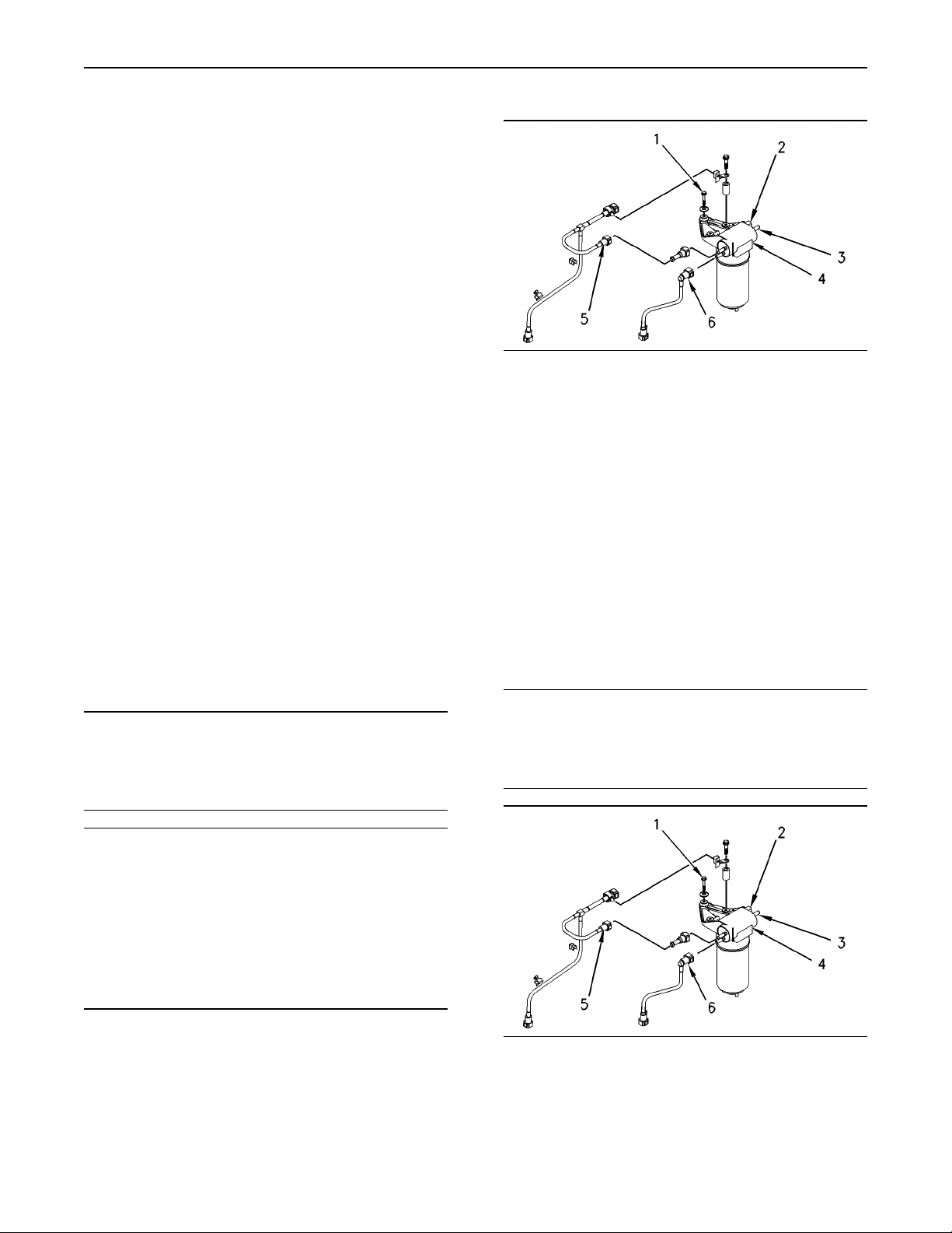
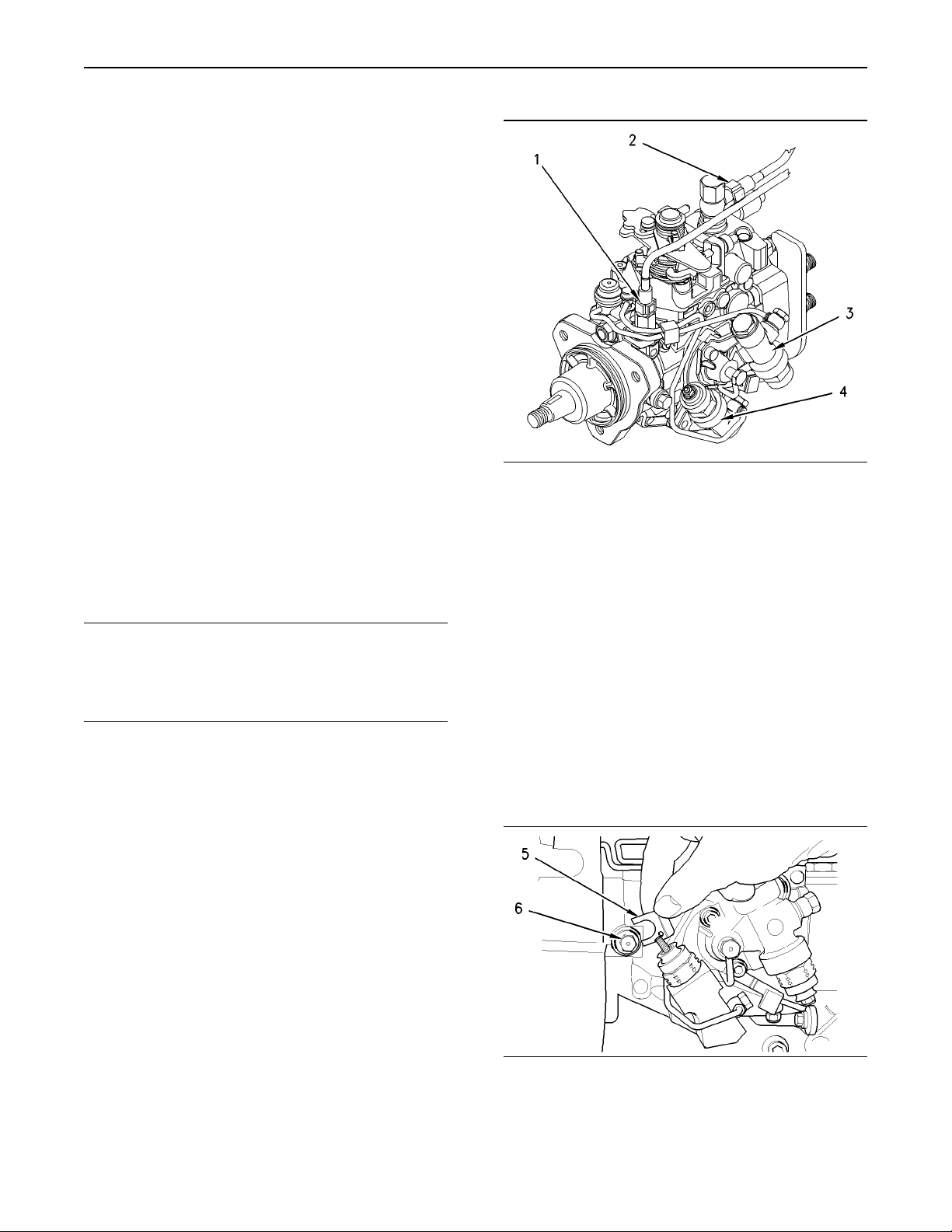
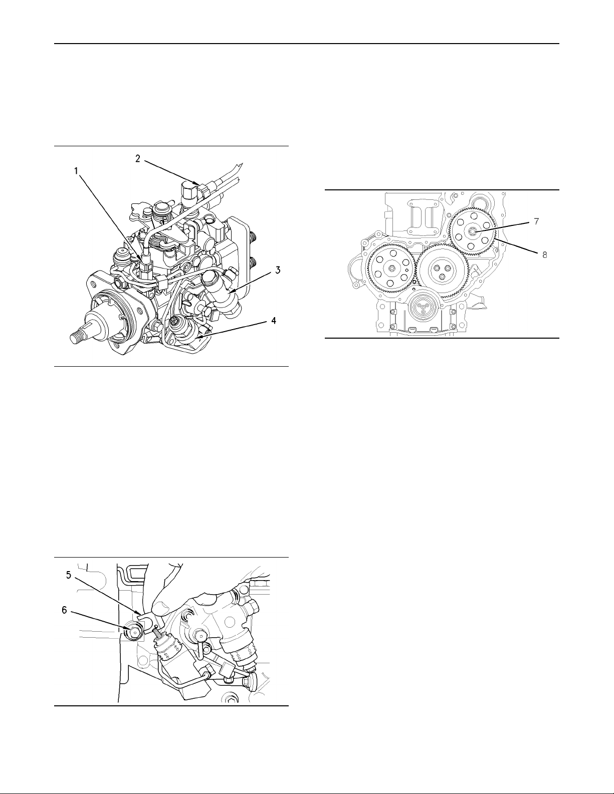
Illustration 1
Typical example
1. Disconnect the tube assembly (5). Disconnect
the tube assembly (6). Install dust covers onto
the connectors for the fuel priming pump.
2. Disconnect the fuel return line from the connector
(3). Install a dust cover to the connector (3).
3. Disconnect the harness assembly from the
connector (2).
4. Support the fuel priming pump. Remove the
three setscrews (1) and discard the rubber
washers. Remove the fuel priming pump (4).
g00952432
Installation Procedure
NOTICE
Keep all parts clean from contaminants.
Contaminants may cause rapid wear and shortened
component life.
NOTICE
Care must be taken to ensure that fluids are contained
during performance of inspection, maintenance, testing, adjusting and repair of theproduct. Be prepared to
collect the fluid with suitable containers before opening any compartment or disassembling any component containing fluids.
Dispose of all fluids according to local regulations and
mandates.
Illustration 2
Typical example
1. Clean the external surfaces of the fuel priming
pump (4). Position the fuel priming pump (4) and
install the setscrews (1) and new rubber washers.
g00952432
Page 5
2. Remove the dust covers from the fuel priming
pump. Remove the plugs from the tube
assemblies. Connect the tube assembly (5).
Connect the tube assembly (6).
3. Connect the fuel return line to the connector (3).
4. Connect the harness assembly to the connector
(2).
5. Remove the air from the fuel system. Refer to
the Operations and Maintenance Manual, “Fuel
System - Prime”.
i01939067
Fuel Filter Base - Remove and
Install
5
Disassembly and Assembly Section
Removal Procedure
Note: There is an option for the three cylinder
engine. The fuel filter and the fuel priming pump
can be installed onto the application rather than
onto the engine. If this is the case, refer to the
appropriate OEM information as well to this text.
NOTICE
Keep all parts clean from contaminants.
Contaminants may cause rapid wear and shortened
component life.
NOTICE
Care must be taken to ensure that fluids are contained
during performance of inspection, maintenance, testing, adjusting and repair of theproduct. Be prepared to
collect the fluid with suitable containers before opening any compartment or disassembling any component containing fluids.
Dispose of all fluids according to local regulations and
mandates.
Note: The removal procedure is identical for the
four cylinder and the three cylinder engines. The
illustrations show the four cylinder engine.
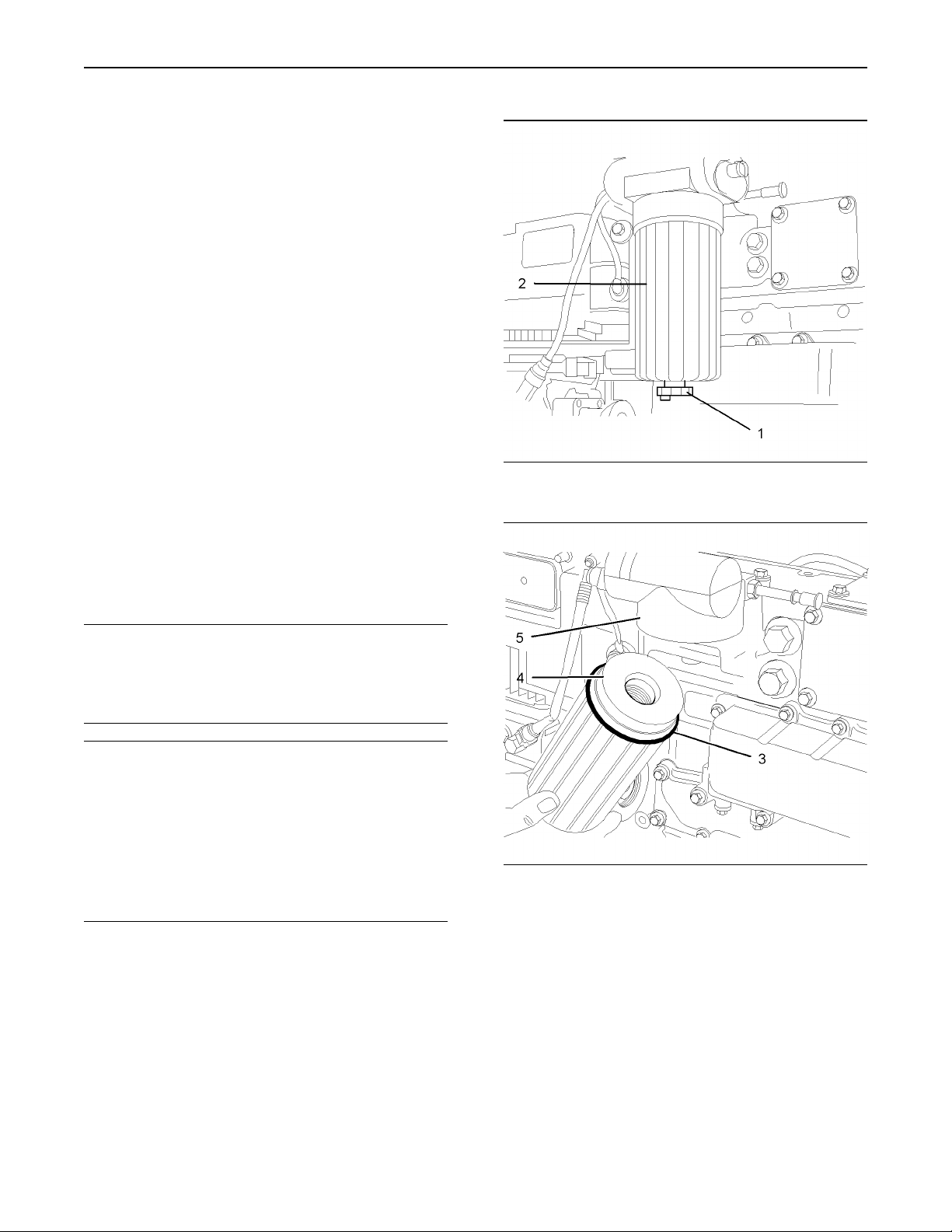
Illustration 3
Typical example
Illustration 4
Typical example
g01010637
g01010595
1. Place a suitable container below the filter in
order to collect the spilled fuel. Thoroughly clean
the outside surfaces of the fuel filter. Open the
drain (1) in order to drain the fuel from the filter.
2. Use a suitable strap wrench to loosen the filter
case (2). Remove the filter case (2) from the filter
head (5).
3. Push down against the spring pressure that is
applied to the filter element (4). Rotate the filter
element (4) counterclockwise in order to release
the filter element from the filter case (2).
4. Discard the filter element (4) and the O-ring (3).
Page 6
6
Disassembly and Assembly Section
Installation Procedure
NOTICE
Keep all parts clean from contaminants.
Contaminants may cause rapid wear and shortened
component life.
Note: The installation procedure is identical for the
four cylinder and the three cylinder engines. The
illustrations show the four cylinder engine.
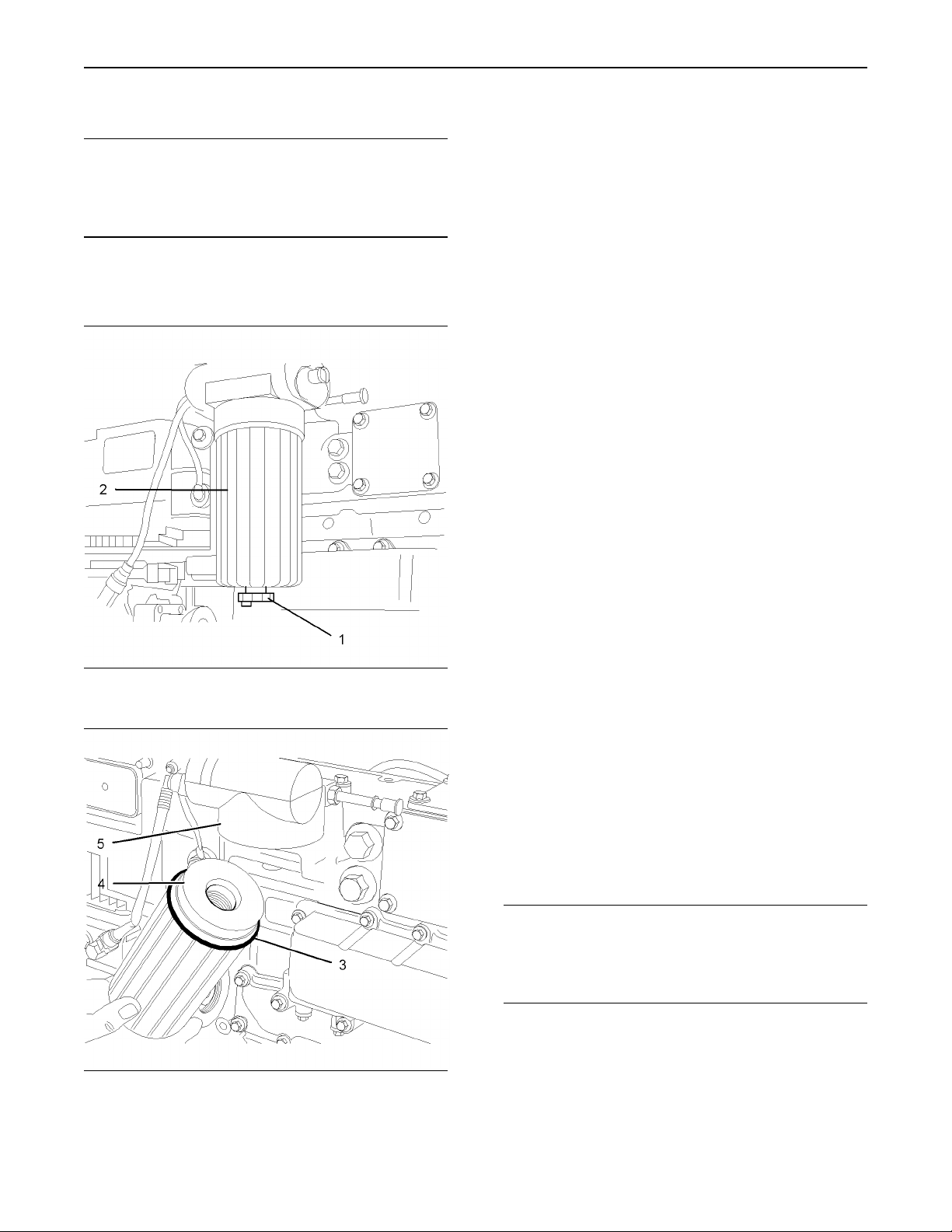
1. Thoroughly clean the inside of the filter case (2)
and thoroughly clean the lower face of the filter
head (5).
2. Inspect the thread of a new filter element (4) in
order to ensure that the thread is not damaged.
Inspect the thread of the adapter in the filter
head (5) in order to ensure that the thread is not
damaged.
3. Inspect the condition of the spring and ensure
that the spring is correctly located within the
filter case (2).
4. Install the new filter element (4) into the filter
case (2). Push the filter element against the
spring pressure and rotate the filter element in
a clockwise direction in order to secure the filter
element within the filter case (2).
5. Lightly lubricate a new O-ring (3) with clean fuel
oil. Install the new O-ring (3) into the recess
within the filter case (2).
6. Close the drain (1).
7. Remove the air from the fuel system. Refer to
the Operations and Maintenance Manual, “Fuel
System - Prime”. Remove the suitable container
and dispose of the fuel that has drained as
waste.
Illustration 5
Typical example
Illustration 6
Typical example
g01010637
g01010595
i01939856
Fuel Injection Lines - Remove
Removal Procedure
Start By:
a. Remove the cover for the fuel injectors. Refer to
this Disassembly and Assembly Manual, “Fuel
Injector Cover - Remove and Install”.
NOTICE
Keep all parts clean from contaminants.
Contaminants may cause rapid wear and shortened
component life.
Page 7
Disassembly and Assembly Section
7
NOTICE
Care must be taken to ensure that fluids are contained
during performance of inspection, maintenance, testing, adjusting and repair of theproduct. Be prepared to
collect the fluid with suitable containers before opening any compartment or disassembling any component containing fluids.
Dispose of all fluids according to local regulations and
mandates.
Note: The removal procedure is identical for four
cylinder and three cylinder engines. The illustration
shows the four cylinder engine.
NOTICE
Care must be taken to ensure that fluids are contained
during performance of inspection, maintenance, testing, adjusting and repair of theproduct. Be prepared to
collect the fluid with suitable containers before opening any compartment or disassembling any component containing fluids.
Dispose of all fluids according to local regulations and
mandates.
Note: The installation procedure is identical for the
four cylinder and the three cylinder engines. The
illustration shows the four cylinder engine.
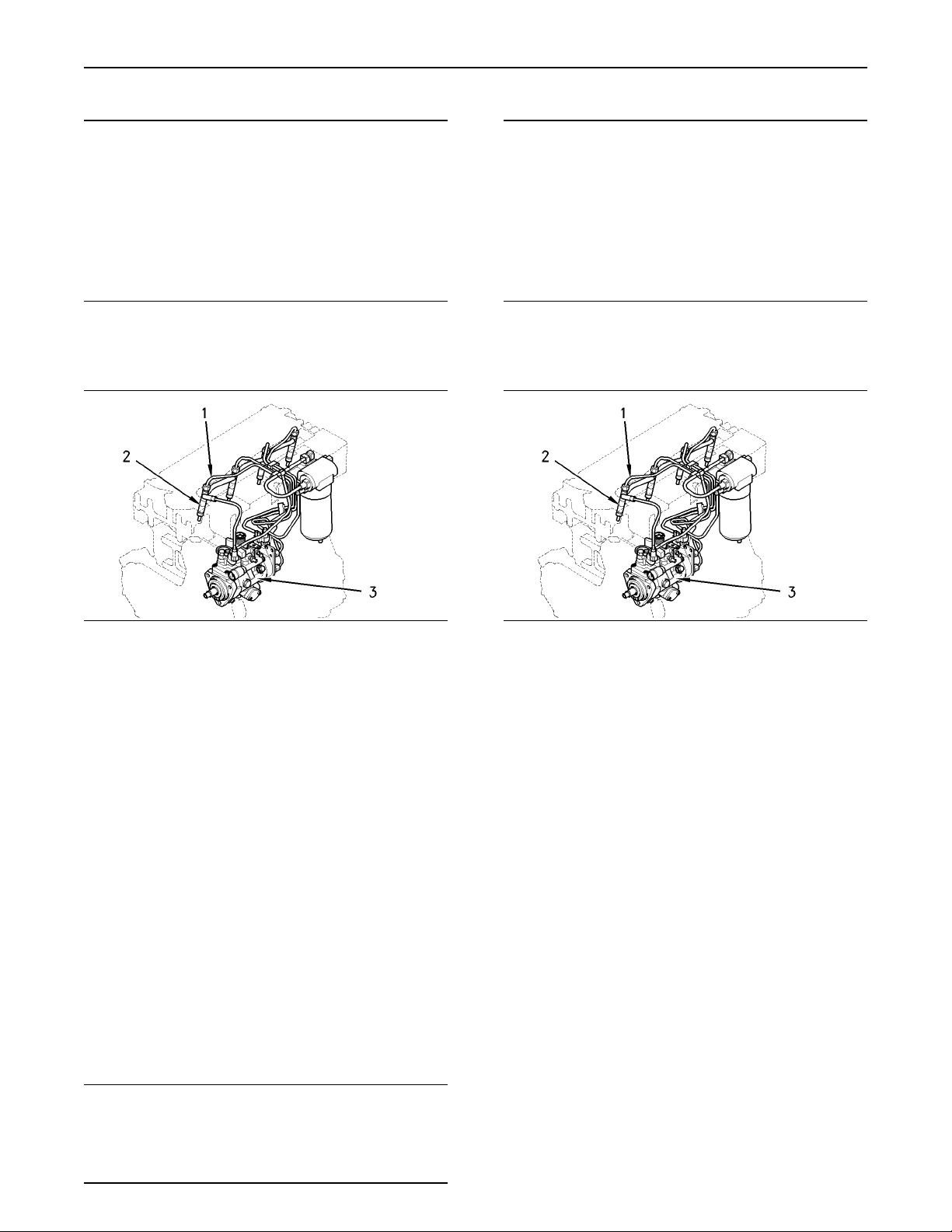
Illustration 7
Typical example
g00955826
1. Disconnect the fuel injection lines (1) at the fuel
injectors (2).
2. Disconnect the fuel injection lines (1) at the fuel
injection pump (3).
3. If it is necessary remove the clamps for the fuel
injection lines or loosen the clamps for the fuel
injection lines. Remove the fuel injection lines (1).
4. Install dust caps onto the ports of the fuel
injectors and onto the ports of the fuel injection
pump. Install dust caps onto both ends of the
fuel injection lines.
i01939857
Fuel Injection Lines - Install
Installation Procedure
Illustration 8
Typical example
g00955826
1. Inspect the fuel injection lines (1) for wear and for
damage. Replace any fuel injection line (1) that
is worn or any fuel injection line that is damaged.
2. Loosely install the clamps for the fuel injection
lines (1).
3. Remove the dust caps from the fuel injection
pump (3) and from the fuel injectors (2). Remove
the dust caps from the fuel injection lines (1).
4. Loosely connect the nuts at both ends of the fuel
injection lines (1).
5. Ensure that each fuel injection line (1) does not
contact any other fuel injection line or any other
engine component. Tighten the fasteners for the
clamps for the fuel injection lines (1). Check that
the fuel injection lines (1) are still clear of other
components.
6. Tighten the fuel injection lines (1) at the fuel
injectors (2) to a torque of 30 N·m (22 lb ft).
NOTICE
Keep all parts clean from contaminants.
Contaminants may cause rapid wear and shortened
component life.
7. Tighten the fuel injection lines (1) at the fuel
injection pump (3) to 30 N·m (22 lb ft).
Page 8
8
Disassembly and Assembly Section
8. Remove the air from the fuel system. Refer to
the Operations and Maintenance Manual, “Fuel
System - Prime”.
End By:
a. Install the cover for the fuel injectors. Refer to
this Disassembly and Assembly Manual, “Fuel
Injector Cover - Remove and Install”.
i01940979
Fuel Injector Cover - Remove
and Install
Removal Procedure
NOTICE
Keep all parts clean from contaminants.
Contaminants may cause rapid wear and shortened
component life.
Installation Procedure
NOTICE
Keep all parts clean from contaminants.
Contaminants may cause rapid wear and shortened
component life.
Note: The installation procedure is identical for the
four cylinder and the three cylinder engines. The
illustration shows the four cylinder engine.
Note: The removal procedure is identical for the
four cylinder and the three cylinder engines. The
illustration shows the four cylinder engine.
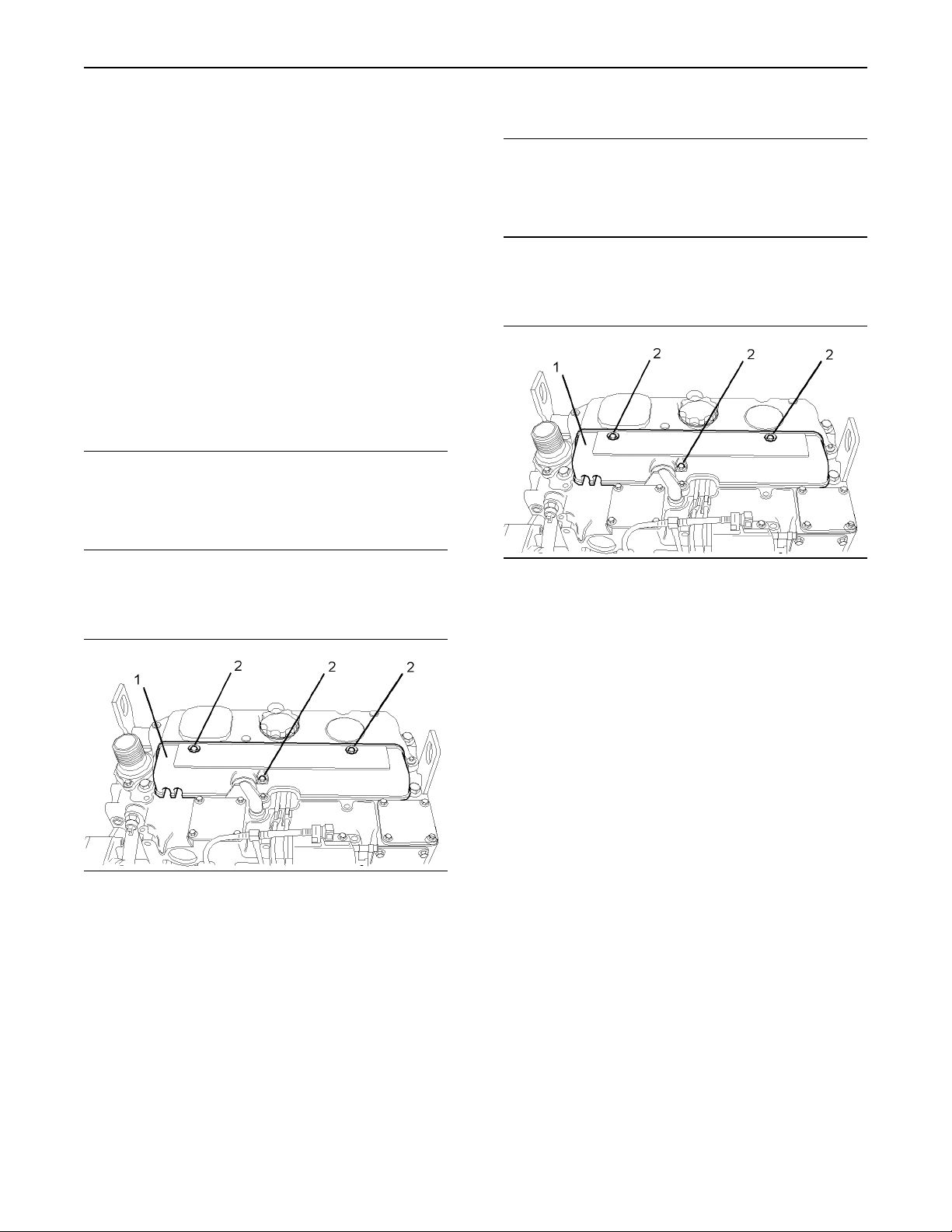
Illustration 9
Typical example
1. Thoroughly clean all of the outer surfaces of the
cover (1) for the fuel injectors.
2. Remove the setscrews (2) from the cover (1).
3. Remove the cover (1).
g01011111
Illustration 10
Typical example
1. Thoroughly clean all of the inner surfaces of the
cover (1) for the fuel injectors.
2. Install the cover (1).
3. Install the setscrews (2) for the cover (1). Tighten
the setscrews (2) to a torque of 9 N·m (7 lb ft).
g01011111
i01940997
Fuel Injection Pump - Remove
(Delphi DP210)
Removal Procedure
Start By:
a. Remove the fuel injection lines. Refer to this
Disassembly and Assembly Manual, “Fuel
Injection Lines - Remove”.
b. Remove the crankshaft pulley. Refer to this
Disassembly and Assembly Manual, “Crankshaft
Pulley - Remove and Install”.
Page 9
Disassembly and Assembly Section
9
c. Remove the front cover. Refer to this Disassembly
and Assembly Manual, “Front Cover - Remove
and Install”.
Note: The removal procedure is identical for the
four cylinder and the three cylinder engines. The
illustrations show the four cylinder engine.
NOTICE
Keep all parts clean from contaminants.
Contaminants may cause rapid wear and shortened
component life.
1. Ensure that the No. 1 cylinder is at top dead
center on the compression stroke. Refer to the
Testing and Adjusting Manual, “Finding Top
Center Position for No. 1 Piston”.
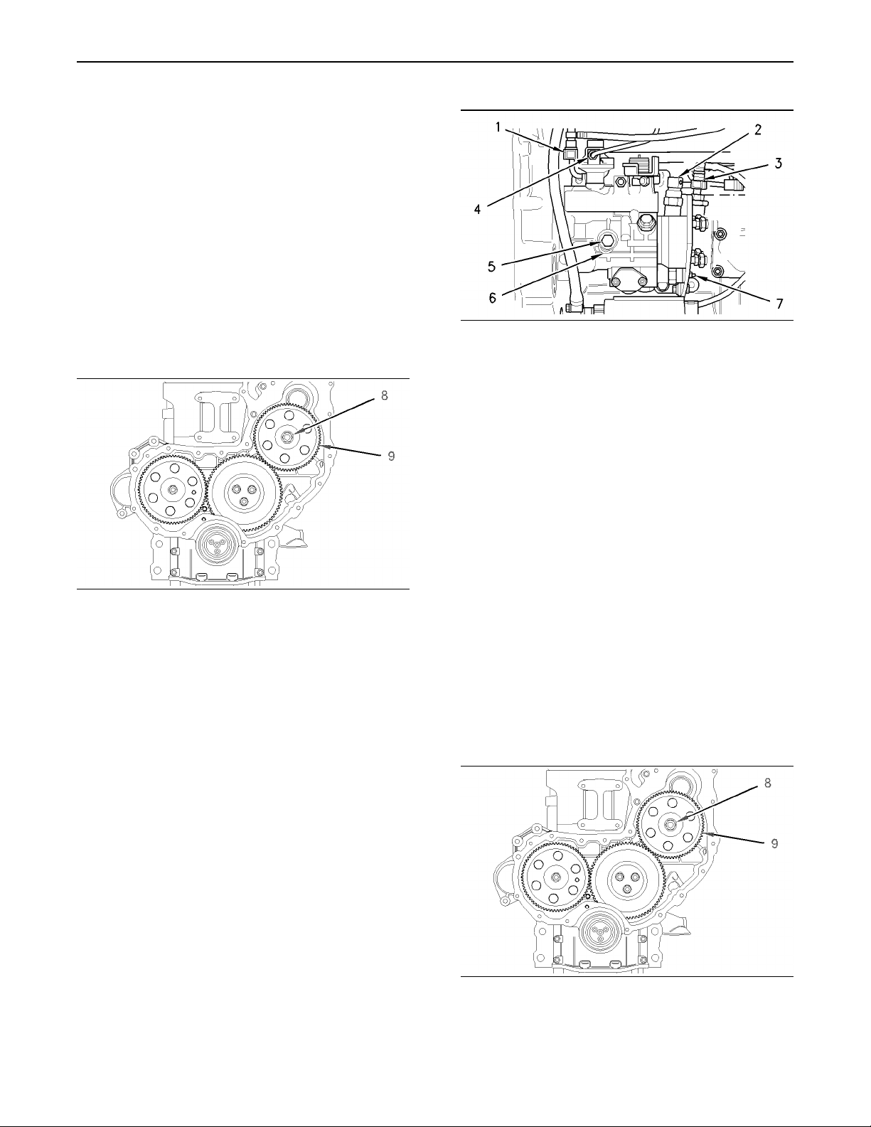
4. Disconnect the fuel line (3).
5. Disconnect the harness assembly (2) from the
timing advance solenoid (7).
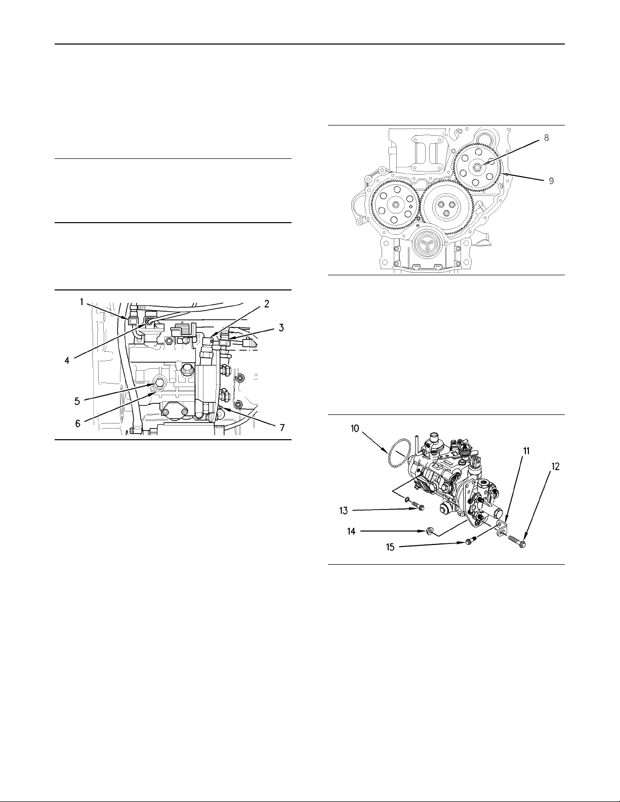
Illustration 12
Typical example
g01011369
6. Remove the nut (8) and the washer from the
shaft of the fuel injection pump.
7. Use a suitable puller in order to remove the fuel
injection pump gear (9).
Illustration 11
Typical example
g00956204
2. Loosen the locking screw (5). Rotate the spacer
(6) in order to allow the locking screw (5) to
tighten against the shaft of the fuel injection
pump. Rotate the fuel injection pump gear in a
counterclockwise direction in order to remove
the backlash. Tighten the locking screw (5) to a
torque of 17 N·m (13 lb ft).
Note: The locking screw (5) must be tightened in
order to prevent the shaft of the fuel injection pump
from rotating. The shaft of the fuel injection pump
must not be rotated after the fuel injection pump
has been removed from the engine.
Note: Put identification marks on all fuel hose
assemblies and on all tube assemblies for
installation purposes. After being disconnected,
plug all fuel hose assemblies and plug all tube
assemblies with suitable plastic plugs. Also install
dust caps on all of the connectors on the fuel
injection pump. This helps prevent fluid loss, and
this helps to keep contaminants from entering the
system.
Note: Do not pry the fuel injection pump gear (9)
from the shaft of the fuel injection pump.
Illustration 13
g00956267
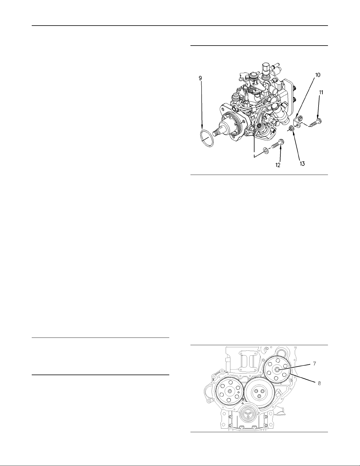
8. Remove the nut (14). Remove the bolt (12).
9. If necessary, remove the setscrew (15) and the
bracket (11) from the cylinder block.
10. Remove the setscrews (13) in order to remove
the fuel injection pump.
11. Remove the fuel injection pump from the front
housing. Remove the O-ring (10) and discard the
O-ring from the fuel injection pump.
3. Disconnect the fuel return line (1). Disconnect the
tube assembly (4) from the fuel injection pump.
Page 10
10
Disassembly and Assembly Section
i01941022
Fuel Injection Pump - Remove
(Bosch EPVE for the 1104
engines only)
Removal Procedure
Start By:
a. Remove the fuel injection lines. Refer to this
Disassembly and Assembly Manual, “Fuel
Injection Lines - Remove and Install”.
b. Remove the crankshaft pulley. Refer to this
Disassembly and Assembly Manual, “Crankshaft
Pulley - Remove and Install”.
c. Remove the front cover. Refer to this Disassembly
and Assembly Manual, “Front Cover - Remove
and Install”.
NOTICE
Keep all parts clean from contaminants.
Illustration 14
Note: Put identification marks on all fuel hose
assemblies and on all tube assemblies for
installation purposes. After being disconnected,
plug all fuel hose assemblies and plug all tube
assemblies with suitable plastic plugs. Also install
dust caps on all of the connectors on the fuel
injection pump. This helps prevent fluid loss, and
this helps to keep contaminants from entering the
system.
g00996409
Contaminants may cause rapid wear and shortened
component life.
1. Ensure that the No. 1 cylinder is at top dead
center on the compression stroke. Refer to the
Testing and Adjusting Manual, “Finding Top
Center Position for No. 1 Piston”.
2. Disconnect the tube assembly (1) from the fuel
injection pump. Disconnect the tube assembly
(2) from the fuel injection pump.
3. Disconnect the wiring harness assembly from
the cold start advance unit (3). Disconnect the
wiring harness assembly from the engine shutoff
solenoid (4).
Illustration 15
g00996410
Page 11
11
Disassembly and Assembly Section
4. Loosen the locking screw (6). Move the spacer
(5) in order to allow the locking screw (6) to
tighten against the shaft of the fuel injection
pump. Rotate the fuel injection pump gear in a
counterclockwise direction in order to remove
the backlash. Tighten the locking screw (6) to a
torque of 31 N·m (23 lb ft).
Note: The locking screw (6) must be tightened in
order to prevent the shaft of the fuel injection pump
from rotating. The shaft of the fuel injection pump
must not be rotated after the fuel injection pump
has been removed from the engine.
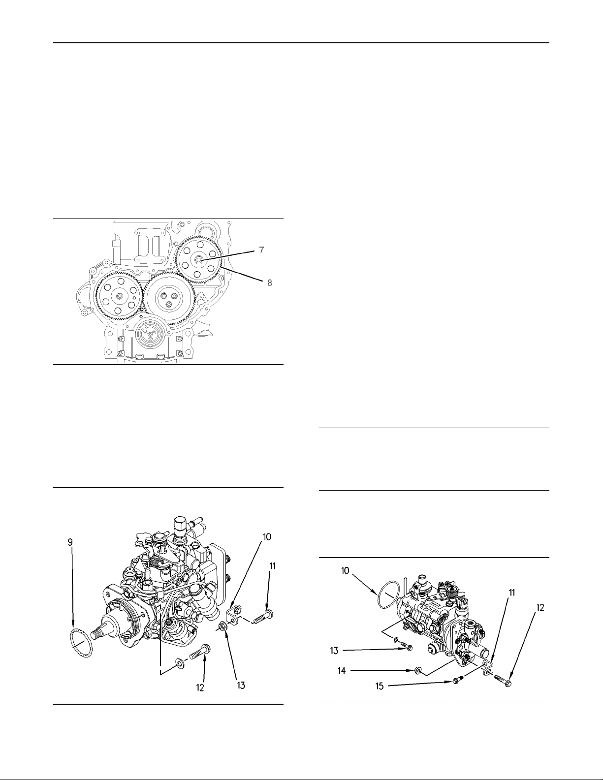
Illustration 16
g01011474
5. Remove the nut (7) and the washer from the
shaft of the fuel injection pump.
6. Use a suitable puller in order to remove the fuel
injection pump gear (8).
Note: Do not pry the fuel injection pump gear from
the shaft of the fuel injection pump.
8. If necessary, remove the setscrew and the
bracket (10) from the cylinder block.
9. Remove the setscrews (12) in order to remove
the fuel injection pump.
10. Remove the fuel injection pump from the front
housing. Remove the O-ring (9) from the fuel
injection pump and discard the O-ring.
i01943876
Fuel Injection Pump - Install
(Delphi DP210)
Installation Procedure
Note: The installation procedure is identical for the
four cylinder and the three cylinder engines. The
illustrations show the four cylinder engine.
Note: The shaft of the fuel injection pump must
remain locked until the timing gear (9) has been
installed and tightened onto the shaft of the fuel
injection pump. The locking screw (5) must remain
locked until you are instructed to loosen the locking
screw. The fuel injection pump must be returned to
your Perkins Dealer if the shaft of the fuel injection
pump was rotated accidentally.
NOTICE
Keep all parts clean from contaminants.
Contaminants may cause rapid wear and shortened
component life.
Illustration 17
g00996474
7. Remove the nut (13). Remove the bolt (11).
1. Ensure that the No. 1 cylinder is at top dead
center on the compression stroke. Refer to the
Testing and Adjusting Manual, “Fuel Injection
Timing - Check”.
Illustration 18
Typical example
g00956267
Page 12
12
Disassembly and Assembly Section
Note: Do not lubricate the new O-ring (10). The
O-ring should be installed dry.
2. Install the new O-ring (10) onto the fuel injection
pump. Position the fuel injection pump onto the
front housing. Install the setscrews (13). Tighten
the setscrews (13) to a torque of 25 N·m (18 lb ft).
3. Install the setscrew (15) and the bracket (11)
onto the cylinder block if the bracket was
previously removed. Ensure that the bracket (11)
supports the fuel injection pump without applying
any other external force on the fuel injection
pump. Tighten the setscrew (15) to a torque of
44 N·m (32 lb ft).
4. Install the bolt (12) and the nut (14).
Illustration 20
Typical example
g00956204
6. Connect the harness assembly to the timing
advance solenoid (7).
7. Connect the harness assembly (2).
Illustration 19
Typical example
g01011369
Note: Ensure that the mating surfaces of the fuel
injection pump gear and the shaft of the fuel
injection pump are clean. Lubricate the threads of
the shaft for the fuel injection pump. The nut (8)
must turn freely until contact is made with the fuel
injection pump gear.
5. Position the fuel injection pump gear (9) onto
the shaft of the fuel injection pump. Install the
washer and the nut (8). Rotate the fuel injection
pump gear (9) in a counterclockwise direction in
order to remove the backlash. Tighten the nut (8)
to a torque of 24 N·m (17 lb ft).
8. Remove all of the dust caps from the connectors
on the fuel injection pump. Remove all of the
plugs from the fuel hose assemblies and from
the tube assemblies.
9. Connect the fuel line (3), the fuel return line (1),
and the tube assembly (4) to the fuel injection
pump.
10. Loosen the locking screw (5). Move the spacer
(6) in order to prevent the locking screw (5) from
tightening against the shaft of the fuel injection
pump. Tighten the locking screw (5) to a torque
of 12 N·m (106 lb in).
Note: The spacer (6) must be correctly positioned
and locking screw (5) must be tightened in order to
prevent the locking screw from contacting the shaft
of the fuel injection pump.
Illustration 21
Typical example
g01011369
Page 13
11. Tighten the nut (8) to a torque of 88 N·m
(65 lb ft).
End By:
a. Install the front cover. Refer to this Disassembly
and Assembly Manual, “Front Cover - Remove
and Install”.
b. Install the crankshaft pulley. Refer to this
Disassembly and Assembly Manual, “Crankshaft
Pulley - Remove and Install”.
c. Install the fuel injection lines. Refer to this
Disassembly and Assembly Manual, “Fuel
Injection Lines - Install”.
i01943877
Fuel Injection Pump - Install
(Bosch EPVE for the 1104
engines only)
Disassembly and Assembly Section
Illustration 22
2. Lightly lubricate a new O-ring (9) with Perkins
1766-501 Silicone Fluid MS200/1000. Install
the new O-ring (9) onto the fuel injection pump.
Position the fuel injection pump on the front
housing. Install the setscrews (12). Tighten the
setscrews to a torque of 25 N·m (18 lb ft).
g00996474
13
Installation Procedure
Note: The shaft of the fuel injection pump must
remain locked until the timing gear (8) has been
installed and tightened onto the shaft of the fuel
injection pump. The locking screw (6) must remain
locked until you are instructed to loosen the locking
screw. The Bosch EPVE fuel injection pump can be
timed to the engine by a technician. Refer to the
Testing and Adjusting Manual, “Fuel Injection Pump
Timing - Check and Fuel Injection Pump Timing Adjust” if the shaft of the fuel injection pump was
rotated accidentally.
NOTICE
Keep all parts clean from contaminants.
Contaminants may cause rapid wear and shortened
component life.
1. Ensure that the No. 1 cylinder is at top dead
center on the compression stroke. Refer to the
Testing and Adjusting Manual, “Fuel Injection
Timing - Check”.
3. Install the setscrew and the bracket (10) onto
the cylinder block if the bracket was previously
removed. Ensure that the bracket (10) supports
the fuel injection pump without applying any
other external force on the fuel injection pump.
Tighten the setscrew to a torque of 44 N·m
(32 lb ft).
4. Install the bolt (11) and the nut (13).
Note: Ensure that the mating surfaces of the fuel
injection pump gear (8) and the shaft of the fuel
injection pump are clean. Lubricate the threads of
the shaft for the fuel injection pump. The nut (7)
must turn freely until contact is made with the fuel
injection pump gear (8).
Illustration 23
g01011474
Page 14
14
Disassembly and Assembly Section
5. Position the fuel injection pump gear (8) onto
the shaft of the fuel injection pump. Install the
washer and the nut (7). Rotate the fuel injection
pump gear (8) in a counterclockwise direction in
order to remove the backlash. Tighten the nut (7)
to a torque of 24 N·m (17 lb ft).
10. Loosen the locking screw (6). Move spacer (5)
in order to prevent the locking screw (6) from
tightening against the shaft of the fuel injection
pump. Tighten the locking screw (6) to a torque
of 12 N·m (106 lb in).
Note: The spacer (5) must be installed and the
locking screw (6) must be tightened in order to
prevent the locking screw from contacting the shaft
of the fuel injection pump.
Illustration 26
g01011474
Illustration 24
g00996409
6. Connect the wiring harness assembly to the
engine shutoff solenoid (4).
7. Connect the wiring harness assembly to the cold
start advance unit (3).
8. Remove all of the dust caps from the connectors
on the fuel injection pump. Remove all of the
plugs from the fuel hose assemblies and from
the tube assemblies.
9. Connect the tube assembly (2) to the fuel
injection pump. Connect the tube assembly (1)
to the fuel injection pump.
11. Tighten the nut (7) to a torque of 88 N·m
(65 lb ft).
End By:
a. Install the front cover. Refer to this Disassembly
and Assembly Manual, “Front Cover - Remove
and Install”.
b. Install the crankshaft pulley. Refer to this
Disassembly and Assembly Manual, “Crankshaft
Pulley - Remove and Install”.
c. Install the fuel injection lines. Refer to this
Disassembly and Assembly Manual, “Fuel
Injection Lines - Install”.
i01938589
Fuel Injector - Remove
Removal Procedure
Start By:
Illustration 25
a. Remove the cover for the fuel injectors. Refer to
this Disassembly and Assembly Manual, “Fuel
Injector Cover - Remove and Install”.
g00996410
Page 15
15
Disassembly and Assembly Section
b. Remove the fuel injection lines. Refer to this
Disassembly and Assembly, “Fuel Injection Lines
- Remove”.
NOTICE
Keep all parts clean from contaminants.
Contaminants may cause rapid wear and shortened
component life.
NOTICE
Care must be taken to ensure that fluids are contained
during performance of inspection, maintenance, testing, adjusting and repair of theproduct. Be prepared to
collect the fluid with suitable containers before opening any compartment or disassembling any component containing fluids.
Dispose of all fluids according to local regulations and
mandates.
1. Disconnect the tube assemblies from the fuel
filter base for the fuel inlet and the fuel outlet.
i01938672
Fuel Injector - Install
Installation Procedure
NOTICE
Keep all parts clean from contaminants.
Contaminants may cause rapid wear and shortened
component life.
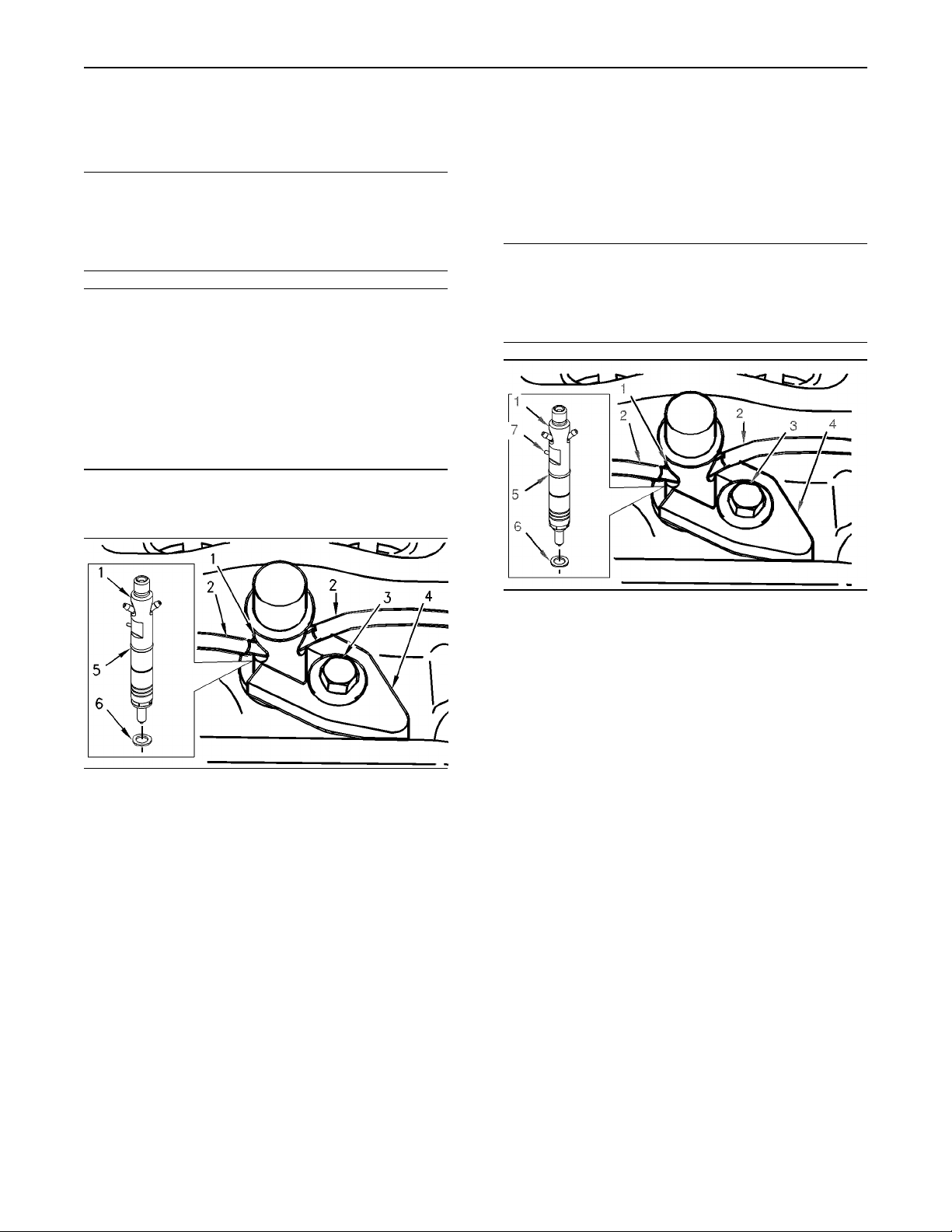
Illustration 27
g00975056
2. Remove the fuel hose (2) from the fuel injector
(1).
3. Remove the setscrew (3). Remove the clamp (4)
from the fuel injector (1).
4. Remove the fuel injector (1) from the cylinder
head. Remove the O-ring seal (5) from the fuel
injector (1) and discard the O-ring.
5. Remove the seat washer (6) from the cylinder
head and discard the seat washer.
Note: If the original seat washer is not removed, the
projection of the fuel injector will be incorrect when
a new seat washer is installed.
Illustration 28
g01008888
1. Lubricate the seat washer (6) with clean engine
oil. Install a new seat washer (6) in the cylinder
head.
Note: If the original seat washer (6) is reused, the
projection of the fuel injector (1) will be incorrect.
2. Install a new O-ring seal (5) on fuel injector (1).
Install the fuel injector (1) in the cylinder head.
Note: Alignment Pin (7) must be located opposite
clamp (4).
3. Position clamp (4) on the fuel injector (1). Install
setscrew (3). Tighten the setscrew to a torque of
27 N·m (20 lb ft).
4. Install hose (2) to the fuel injector (1).
End By:
a. Install the fuel injection lines. Refer to this
Disassembly and Assembly, “Fuel Injection Lines
- Install”.
b. Install the cover for the fuel injectors. Refer to
this Disassembly and Assembly Manual, “Fuel
Injector Cover - Remove and Install”.
Page 16
16
Disassembly and Assembly Section
i01944022
Turbocharger - Remove
Removal Procedure
NOTICE
Keep all parts clean from contaminants.
Contaminants may cause rapid wear and shortened
component life.
NOTICE
Care must be taken to ensure that fluids are contained
during performance of inspection, maintenance, testing, adjusting and repair of theproduct. Be prepared to
collect the fluid with suitable containers before opening any compartment or disassembling any component containing fluids.
Dispose of all fluids according to local regulations and
mandates.
4. If an exhaust elbow is installed, remove the
exhaust elbow. Refer to this Disassembly and
Assembly Manual, “Exhaust Elbow - Remove
and Install”.
5. Remove the nuts (2) and remove the exhaust
adapter (3) from the turbocharger (1).
6. Place a suitable container below the turbocharger
(1) in order to collect any spillage of oil.
Note: The removal procedure is identical for the
three cylinder and the four cylinder engines.
1. Thoroughly clean the outer surfaces of the
turbocharger (1).
2. Loosen the hose clamps and remove the air inlet
hose at the turbocharger compressor housing.
Note: Exhaust elbows are only an option for the four
cylinder engines.
3. Remove the exhaust pipe from the turbocharger
outlet or remove the exhaust pipe from the
exhaust elbow. Refer to the OEM provided
information for the correct procedure in order to
remove the exhaust pipe.
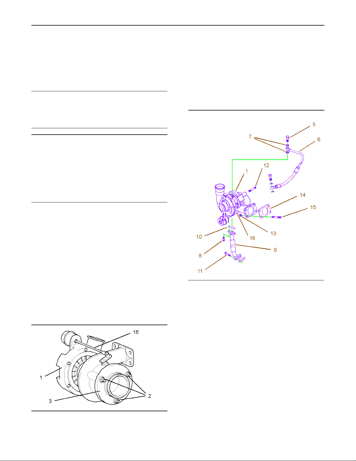
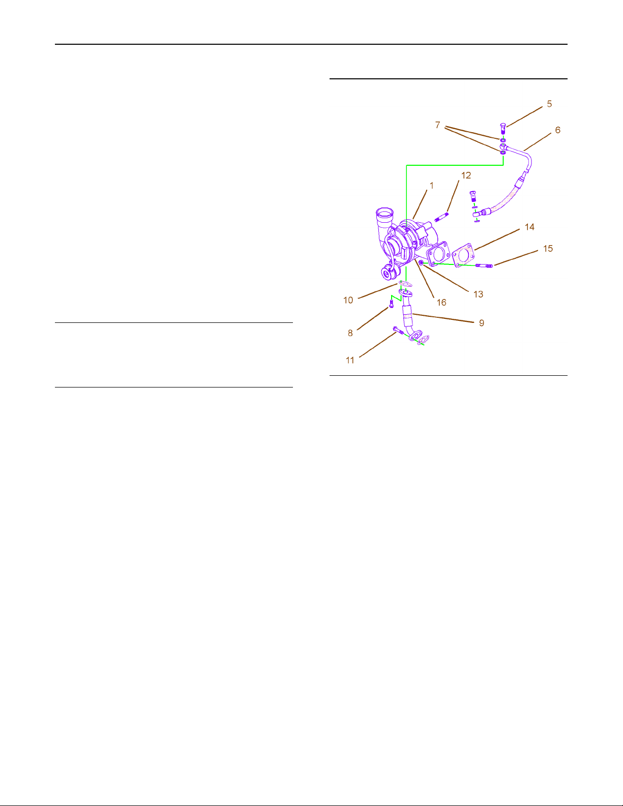
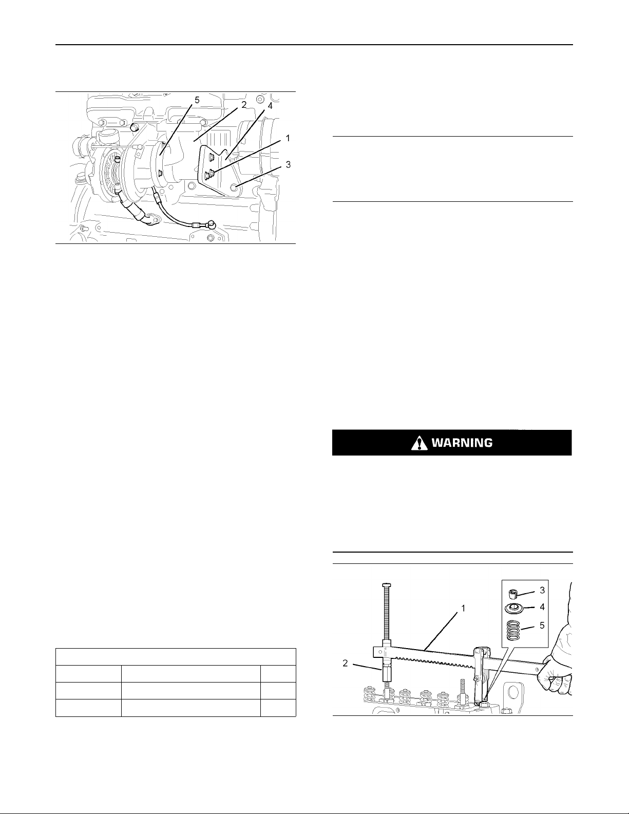
Illustration 30
Typical example
g01038396
7. Remove the banjo bolts (5). Remove the oil
supply tube assembly (6) and the washers (7)
from the turbocharger (1). Discard the washers
(7). If necessary, remove the oil supply tube
assembly (6) from the cylinder block and discard
the washers.
8. Remove the setscrews (8). Remove the oil drain
tube assembly (9) from the turbocharger (1).
Remove the joint (10) and discard the joint.
If necessary, remove the setscrews (11) and
remove the oil drain tube assembly (9) from the
cylinder block. Discard the joint.
Illustration 29
Typical example
g01038600
9. If necessary, remove the studs (12) from the
turbocharger housing.
Note: Do not use the actuator rod of the wastegate
(16) to lift the turbocharger (1).
Page 17
10. Remove the nuts (13). Remove the turbocharger
(1). Remove the gasket (14). Discard the gasket
(14). If necessary, remove the studs (15) from
the exhaust manifold.
11. Install suitable plastic plugs into the oil supply
and into the oil drain ports of the turbocharger
(1). Install suitable plastic covers to the inlet
and to the outlet of the turbocharger (1). Install
suitable plastic plugs to the oil supply tube
assembly (6) and to the oil drain tube assembly
(9). Install suitable plastic covers to the manifold
ports.
i01944024
Turbocharger - Install
Installation Procedure
17
Disassembly and Assembly Section
NOTICE
Keep all parts clean from contaminants.
Contaminants may cause rapid wear and shortened
component life.
Note: The installation procedure is identical for the
three cylinder and the four cylinder engines.
1. Remove all of the plastic plugs from all of
the ports of the turbocharger (1). Clean the
mating surfaces of the exhaust manifold and the
turbocharger. Clean the mating surfaces of the
turbocharger to the oil supply tube assembly
(6) and the turbocharger to the oil drain tube
assembly (9).
2. Ensure that all of the turbocharger inlet and
outlet ports are clean and free from restrictions.
The turbocharger shaft must rotate freely.
Illustration 31
Typical example
3. If the studs (15) were previously removed, install
the studs into the exhaust manifold. Install a new
gasket (14) over the studs (15).
Note: Do not use any sealant on the gasket (14).
Note: Do not use the actuator rod of the wastegate
(16) to lift the turbocharger (1).
4. Position the turbocharger (1) onto the exhaust
manifold.
5. Install the nuts (13). Tighten the nuts (13) to a
torque of 47 N·m (35 lb ft).
6. Lubricate the bearing housing of the turbocharger
(1) with clean engine oil.
7. Inspect all of the oil hose assemblies (6 and
9). If necessary, replace the hose assemblies
(6 and 9).
g01038396
Note: The top flange of the oil drain tube assembly
(9) is secured to the turbocharger (1) with 6 mm
setscrews (8). The bottom flange of the oil drain
tube assembly (9) is secured to the cylinder block
with 8 mm setscrews (11).
8. Position a new joint (10) and the oil drain tube
assembly (9) onto the bottom of the turbocharger
(1). Install the 6 mm setscrews (8). Tighten the 6
mm setscrews (8) to a torque of 9 N·m (80 lb in).
Page 18
18
Disassembly and Assembly Section
9. Position a new joint and the oil drain tube
assembly (9) onto the cylinder block. Tighten
the 8 mm setscrews (11) to a torque of 22 N·m
(16 lb ft).
10. Position the new washers (7) and the oil supply
tube assembly (6) onto the turbocharger (1).
Install the banjo bolt (5). Tighten the banjo bolt
(5) to a torque of 22 N·m (16 lb ft).
Note: Ensure that the oil supply tube assembly
(6) does not come into contact with any other
component when the assembly is installed onto
the engine.
11. Install the new washers and the oil supply tube
assembly (6) to the cylinder block. Tighten the
banjo bolt to a torque of 22 N·m (16 lb ft).
12. If the studs (12) were previously removed, install
the studs into the turbocharger housing.
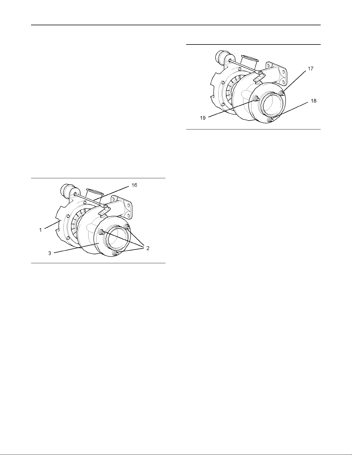
Illustration 33
15. Tighten the three nuts finger tight in the
sequence (17), (18), and (19). Tighten the nuts
(17), (18), and (19) in the same sequence to a
torque of 25 N·m (18 lb ft).
16. Ensure that there is no restriction in the
inlet hose. Position the air inlet hose on the
turbocharger compressor housing. Install the
hose clamps. Tighten the hose clamps to a
torque of 5 N·m (44 lb in).
g01038456
Illustration 32
Typical example
13. Position the exhaust adapter (3) onto the studs
(12). Install the nuts (2). Do not tighten the nuts
(2) at this time.
Note: Exhaust elbows are only an option for the four
cylinder engines.
14. If equipped, install the exhaust elbow onto the
exhaust adapter (3). Refer to this Disassembly
and Assembly Manual, “Exhaust Elbow - Remove
and Install”.
g01038406
Note: The air inlet hose has a reflective heat shield
that partially covers the hose. The reflective heat
shield must be installed toward the engine. The
reflective heat shield must be kept clean and free
from dust, oil or paint.
Note: Apply a solution of water and 5% soap to the
inlet of the turbocharger in order to install a new
air inlet hose. Do not use oil or grease in order to
install the air inlet hose.
17. Position the exhaust pipe onto the exhaust
elbow or onto the turbocharger outlet (3). Refer
to the OEM information for the correct procedure
in order to install the exhaust pipe.
i01946913
Exhaust Manifold - Remove
and Install
Removal Procedure for the Three
Cylinder Engine
Start By:
a. Remove the turbocharger, if equipped. Refer
to this Disassembly and Assembly Manual,
“Turbocharger - Remove”.
Page 19
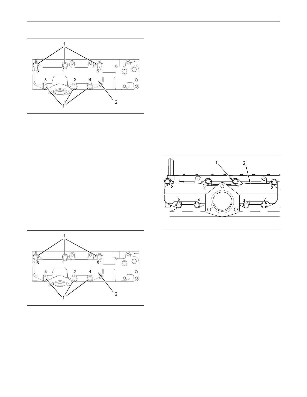
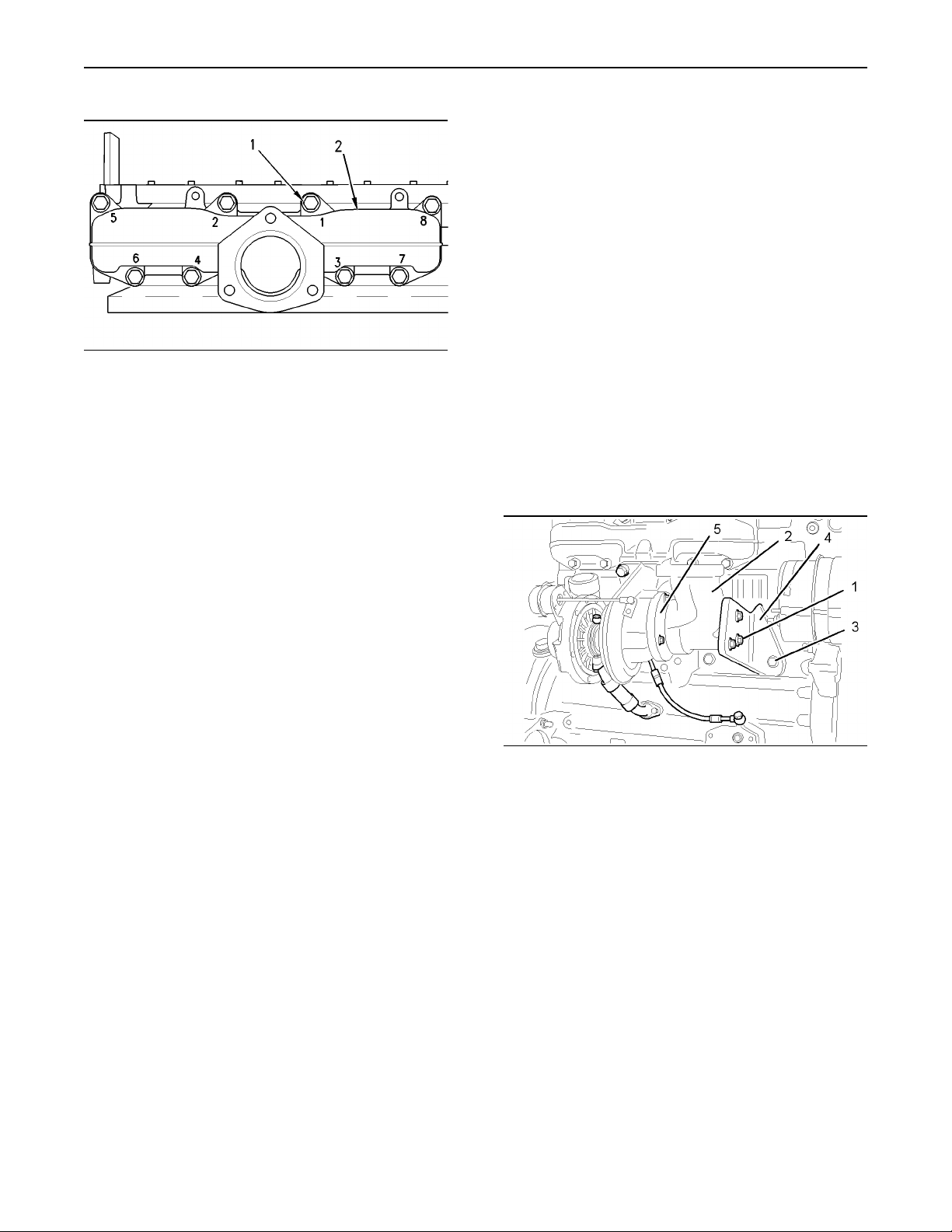
Illustration 34
1. Remove the setscrews (1) in the reverse
numerical order to the Illustration 34. This will
help to prevent any distortion of the exhaust
manifold (2).
2. Remove the exhaust manifold gasket from the
cylinder head and remove the exhaust manifold
(2). Discard the exhaust manifold gasket.
g01038601
19
Disassembly and Assembly Section
3. Remove the two studs and install the remaining
setscrews (1). Ensure that the setscrews (1)
are tightened in the sequence that is shown in
Illustration 35. Tighten the setscrews evenly to a
torque of 33 N·m (24 lb ft).
End By:
a. Install the turbocharger, if equipped. Refer
to this Disassembly and Assembly Manual,
“Turbocharger - Install”.
Removal Procedure for the Four
Cylinder Engine
Start By:
a. Remove the turbocharger, if equipped. Refer
to this Disassembly and Assembly Manual,
“Turbocharger - Remove”.
Installation Procedure for the Three
Cylinder Engine
Note: The improper installation of the exhaust
manifold (2) can result in a cracked exhaust
manifold. The setscrews (1) for the exhaust manifold
must be tightened in the correct sequence and
tightened to the correct torque.
Illustration 35
1. Loosely install two suitable studs into the holes
(5 and 6) as guides.
Note: Do not use any sealant on the exhaust
manifold gasket.
g01038601
Illustration 36
1. Remove the setscrews (1) in the reverse
numerical order to the Illustration 36. This will
help to prevent any distortion of the exhaust
manifold (2).
2. Remove the exhaust manifold gasket from the
cylinder head and remove the exhaust manifold
(2). Discard the exhaust manifold gasket.
g00951398
Installation Procedure for the Four
Cylinder Engine
Note: The improper installation of the exhaust
manifold (2) can result in a cracked exhaust
manifold. The setscrews (1) for the exhaust manifold
must be tightened in the correct sequence and
tightened to the correct torque.
2. Position the new exhaust manifold gasket onto
the studs in the cylinder head. Position the
exhaust manifold (2) onto the studs. Install the
setscrews (1) finger tight in order to secure the
exhaust manifold to the cylinder head.
Page 20
20
Disassembly and Assembly Section
i01946915
Exhaust Elbow - Remove and
Install
(Option for Four Cylinder
Engines Only)
Illustration 37
1. Loosely install two suitable studs into the holes
(5 and 8) as guides.
Note: Do not use any sealant on the exhaust
manifold gasket.
2. Position the new exhaust manifold gasket onto
the studs in the cylinder head. Position the
exhaust manifold (2) onto the studs. Install the
setscrews (1) finger tight in order to secure the
exhaust manifold to the cylinder head.
3. Remove the two studs and install the remaining
setscrews (1). Ensure that the setscrews (1)
are tightened in the sequence that is shown in
Illustration 37. Tighten the setscrews evenly to a
torque of 33 N·m (24 lb ft).
End By:
a. Install the turbocharger, if equipped. Refer
to this Disassembly and Assembly Manual,
“Turbocharger - Install”.
g00951398
Removal Procedure
Start By:
a. Remove the exhaust pipe. Refer to the OEM
information for the correct procedure in order to
remove the exhaust pipe.
Illustration 38
Typical example
g01013687
1. Remove the setscrews (1) from the exhaust
elbow (2). Remove the setscrews (3) and remove
the bracket (4) from the cylinder block. Remove
the exhaust elbow (2) from the exhaust adapter
(5).
Page 21
21
Disassembly and Assembly Section
Installation Procedure
Illustration 39
Typical example
1. Thoroughly clean the exhaust elbow (2) and the
exhaust adapter (5).
2. Install the exhaust elbow (2) onto the exhaust
adapter (5). Position the bracket (4) onto the
cylinder block and install the setscrews (3).
Tighten the setscrews (3) finger tight. Align the
exhaust elbow with the bracket (4). Install the
setscrews (1) in order to secure the exhaust
elbow (2) to the bracket (4). Tighten the
setscrews (3) and tighten the setscrews (1) to a
torque of 44 N·m (33 lb ft).
g01013687
Start By:
a. Remove the rocker shaft assembly. Refer to this
Disassembly and Assembly Manual, “Rocker
Shaft and Pushrod - Remove”.
NOTICE
Keep all parts clean from contaminants.
Contaminants may cause rapid wear and shortened
component life.
Note: The following procedure should be adopted in
order to remove the valve springs when the cylinder
head is still installed onto the cylinder block. Refer
to this Disassembly and Assembly Manual, “Inlet
and Exhaust Valves - Remove and Install” for the
correct procedure that should be used to remove
the valve springs from a cylinder head that has
been removed from the cylinder block.
Note: Ensure that the appropriate piston is at top
dead center before the valve spring is removed.
Failure to ensure that the piston is at top dead
center may allow the valve to drop into the cylinder
block.
1. Use the following procedure in order to find
the top dead center position for the appropriate
piston.
.
End By:
a. Install the exhaust pipe. Refer to the OEM
information for the correct procedure in order to
install the exhaust pipe.
i01947651
Inlet and Exhaust Valve
Springs - Remove and Install
Removal Procedure
Ta bl e 1
Required Tools
Part Number Part Description
21825666
27610235
Valve Spring Compressor
Setscrew Adapter
Qty
Personal injury can result from being struck by
parts propelled by a released spring force.
Make sure to wear all necessary protective equipment.
Follow the recommended procedure and use all
recommended tooling to release the spring force.
1
1
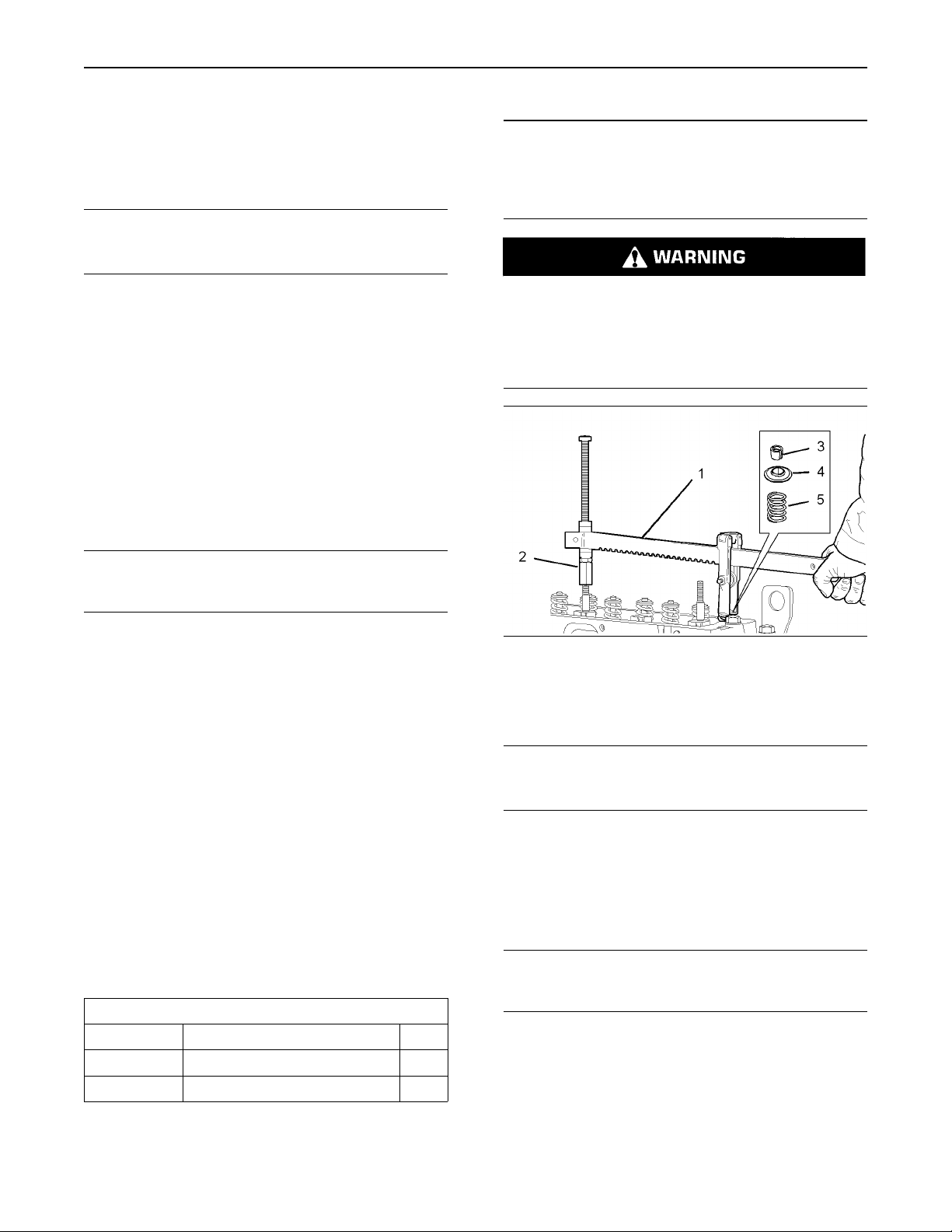
Illustration 40
g01015085
Page 22
22
Disassembly and Assembly Section
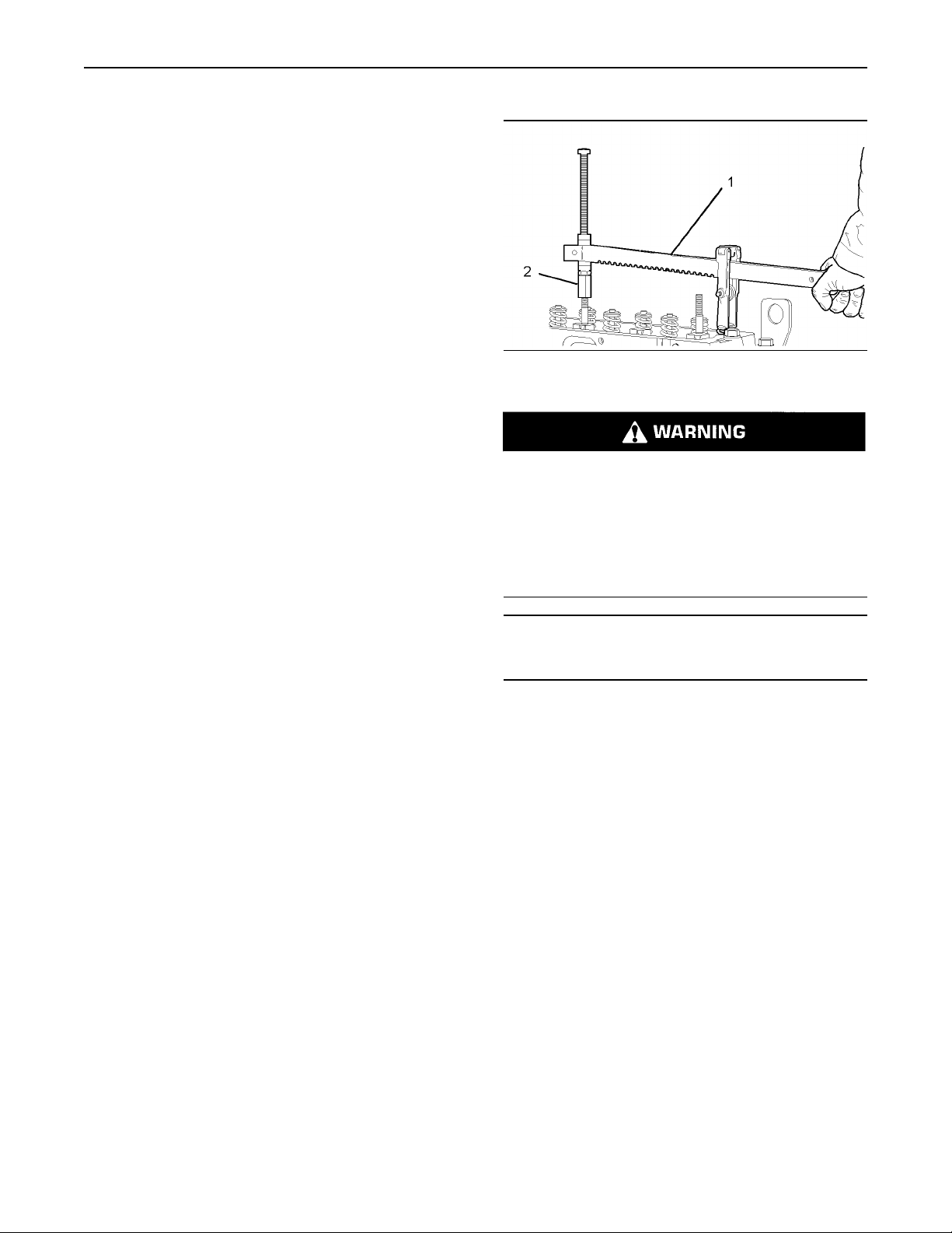
a. Install 21825666 Valve Spring Compressor
(1) and the appropriate 27610235 Setscrew
Adapter (2) in position on the cylinder head
in order to compress the appropriate valve
spring (5).
NOTICE
Ensure that the valve spring is compressed squarely
or damage to the valve stem may occur.
NOTICE
Keep all parts clean from contaminants.
Contaminants may cause rapid wear and shortened
component life.
b. Compress the valve spring (5) sufficiently in
order to open the valve only. Do not compress
the valve spring sufficiently so that the valve
keepers (3) could be removed from the recess
in the valve stem.
c. Turn the crankshaft until the piston touches
the valve.
d. Continue to turn the crankshaft until the valve
stem is at the highest point. The piston is
now at top dead center. Release the applied
pressure of the valve spring compressor (1)
at the top center position.
NOTICE
Do not turn the crankshaft while the valve springs are
removed.
2. Use the valve spring compressor (1) in order to
compress the valve spring (5). Remove the valve
keepers (3).
3. Carefully release the pressure on the valve
spring compressor (1). Remove the valve spring
retainer (4) and the valve spring (5).
Note: If you are replacing all of the valve springs,
the procedure can be done on two cylinders at the
same time. The procedure can be done on cylinder
1 and cylinder 4, and on cylinder 2 and cylinder 3.
Remember that the crankshaft must not be turned
while the valve springs are removed. Ensure that all
of the valve springs are installed before changing
from one pair of cylinders to the other pair of
cylinders.
Improper assembly of parts that are spring loaded
can cause bodily injury.
To prevent possible injury, follow the established
assembly procedure and wear protective equipment.
Illustration 41
g01015085
1. Place the new valve spring (5) into position.
2. Install the valve spring retainer (4).
NOTICE
Ensure that the valve spring is compressed squarely
or damage to the valve stem may occur.
3. Install the valve spring compressor (1) in position
on the cylinder head in order to compress the
appropriate valve spring (5). Compress the valve
spring (5).
4. Install the valve keepers (3).
Installation Procedure
Ta bl e 2
Required Tools
Part Number Part Description
21825666
27610235
Valve Spring Compressor
Setscrew
NOTICE
Do not turn the crankshaft while the valve springs are
removed.
Qty
1
1
Page 23
5. Carefully release the pressure on the valve
spring compressor (1). Remove the valve spring
compressor (1). Ensure that all of the valves are
secured in place by a valve spring and valve
keepers. Rotate the crankshaft through about
45 degrees in order to clear the piston from the
valve. Lightly strike the top of the valve with a
soft hammer in order to ensure that the valve
keepers (3) are properly installed.
Note: If you are replacing all of the valve springs
the procedure can be done on two cylinders at the
same time. The procedure can be done on cylinder
1 and cylinder 4, and on cylinder 2 and cylinder 3.
End By:
a. Install the rocker shaft assembly. Refer to this
Disassembly and Assembly, “Rocker Shaft and
Pushrod - Install”.
23
Disassembly and Assembly Section
i01947652
Inlet and Exhaust Valves Remove and Install
Removal Procedure
Ta bl e 3
Required Tools
Part Number Part Description
21825496
21825666
27610235
Valve Depth Gauge
Valve Spring Compressor
Setscrew Adapter 1
Start By:
a. Remove the cylinder head assembly. Refer to this
Disassembly and Assembly Manual, “Cylinder
Head - Remove”.
Note: Ensure that the machined face of the cylinder
head is kept on a clean, soft surface in order to
prevent damage to the machined surface.
Qty
1
1
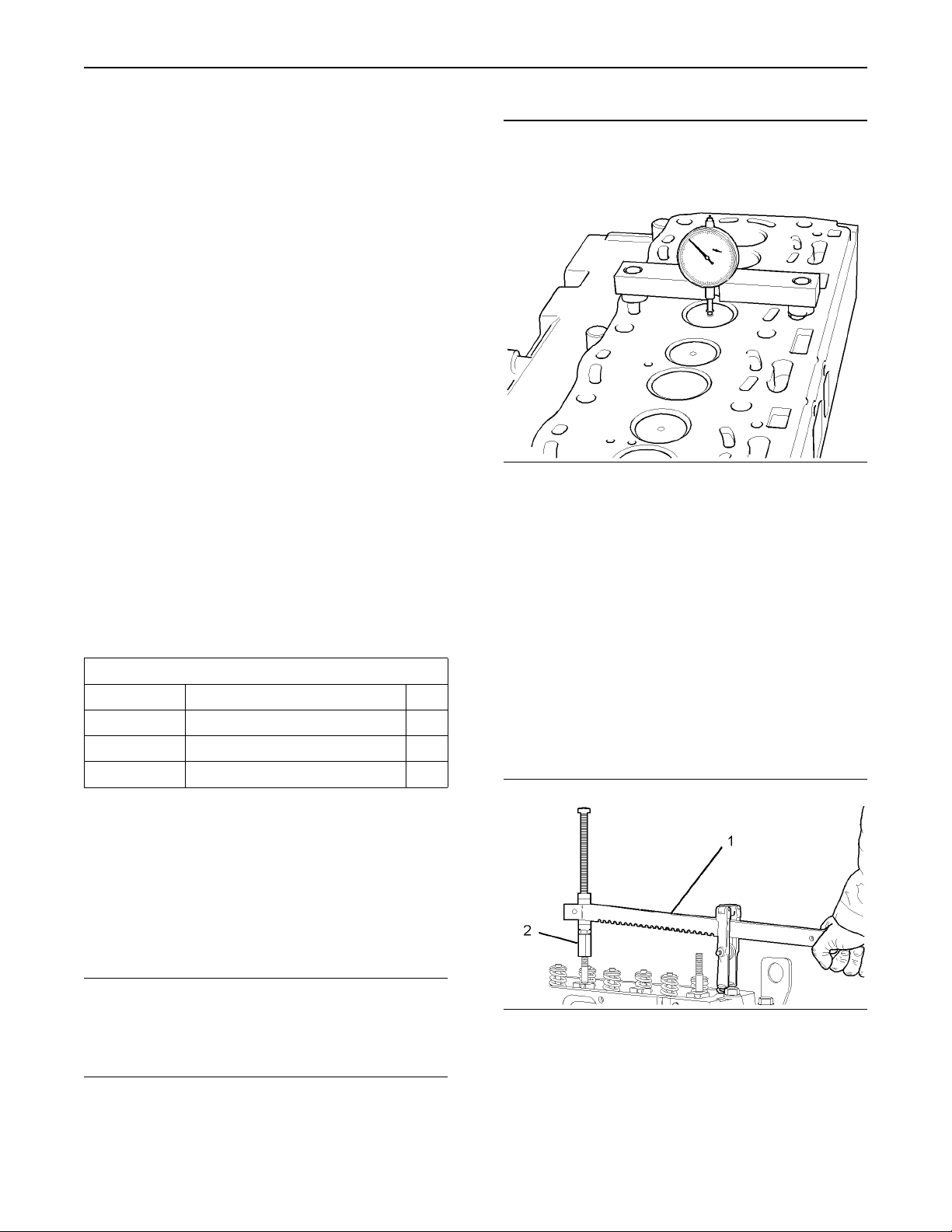
Illustration 42
Typical example
g01015306
1. Use a dial indicator to check the depth of the
valves below the face of the cylinder head
before the valve springs are removed. Refer to
the illustration 42 and refer to Specifications,
“Cylinder Head Valves” for the correct
dimensions.
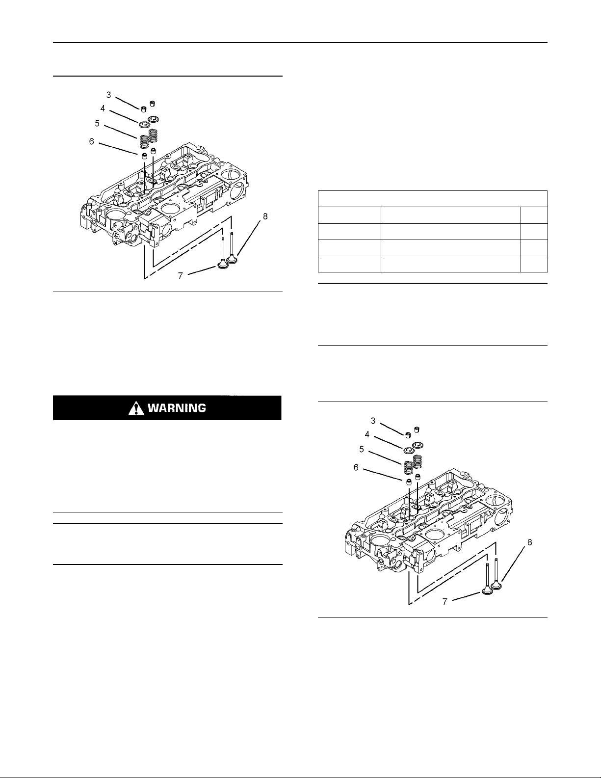
Note: The head of the inlet valve has a larger
diameter than the head of the exhaust valve.
2. Place a numerical index mark on the heads of
the inlet valves and on the exhaust valves so
that each valve can be installed in the correct
sequence during installation.
NOTICE
Keep all parts clean from contaminants.
Contaminants may cause rapid wear and shortened
component life.
Note: The removal procedure is identical for the
three cylinder and the four cylinder engines. The
illustrations show the four cylinder engine.
Illustration 43
Typical example
g01015303
Page 24
24
Disassembly and Assembly Section
9. Remove the valve stem seal (6). Discard the
valve stem seal (6).
10. Remove the appropriate valve (7 or 8).
11. Repeat Step 3 to Step 10 for each inlet valve (7)
and for each exhaust valve (8).
Installation Procedure
Ta bl e 4
Required Tools
Part Number Part Description
21825666
27610235
21825496
Valve Spring Compressor
Setscrew Adapter
Valve Depth Gauge
Qty
1
1
1
Illustration 44
Typical example
g01015305
3. Install 21825666 Valve Spring Compressor
(1) and the appropriate 27610235 Setscrew
Adapter (2) in position on the cylinder head in
order to compress the appropriate valve spring
(5).
Personal injury can result from being struck by
parts propelled by a released spring force.
Make sure to wear all necessary protective equipment.
Follow the recommended procedure and use all
recommended tooling to release the spring force.
NOTICE
Ensure that the valve spring is compressed squarely
or damage to the valve stem may occur.
NOTICE
Keep all parts clean from contaminants.
Contaminants may cause rapid wear and shortened
component life.
Note: The installation procedure is identical for the
three cylinder and the four cylinder engines. The
illustrations show the four cylinder engine.
4. Compress the valve spring (5).
5. Remove the valve keepers (3).
6. Carefully release the pressure on the valve
spring compressor (1). Remove the valve spring
compressor (1) and the setscrew adapter (2)
from the cylinder head.
7. Remove the valve spring retainer (4).
8. Remove the valve spring (5).
Illustration 45
Typical example
g01015305
Page 25
1. Carefully clean the bottom face of the cylinder
head. Ensure that there is no debris in the inlet
and exhaust ports. Also ensure that there is no
debris in the coolant passages and in lubrication
passages. Inspect the cylinder head. Refer to
the Testing and Adjusting Manual, “Cylinder
Head Inspect” for further information.
2. Inspect all of the valve seats for wear and for
damage. Refer to the Specifications Manual,
“Cylinder Head Valves” for further information.
Also refer to this Disassembly and Assembly
Manual, “Inlet and Exhaust Valve Seat Inserts
- Remove and Install” and refer to Testing and
Adjusting Manual, “Valve Depth - Inspect ” for
further information. Replace any worn parts.
3. Inspect all of the valve guides for wear and for
damage. Refer to the Specifications Manual,
“Cylinder Head Valves” for further information.
Also refer to this Disassembly and Assembly
Manual, “Inlet and Exhaust Valve Guides Remove and Install” and refer to Testing and
Adjusting Manual, “Valve Guide - Inspect” for
further information. Replace any worn parts.
25
Disassembly and Assembly Section
Illustration 46
Typical example
g01015303
Personal injury can result from being struck by
parts propelled by a released spring force.
Make sure to wear all necessary protective equipment.
4. Inspect the valves if the valves are not
replacement parts. Refer to the Specifications
Manual, “Cylinder Head Valves” for further
information.
5. Lubricate the stems of all of the inlet valves (7)
and lubricate the stems of all of the exhaust
valves (8) with clean engine oil. Install the inlet
valves (7) and the exhaust valves (8) in the
appropriate positions.
6. Carefully turn over the cylinder head and ensure
that all of the valves remain in place. Place the
machined surface of the cylinder head onto a
clean, soft surface.
Note: The valve guides must be clean and dry
before installing the valve stem seals (6).
7. Install a new valve stem seal (6) onto each of
the valve guides.
8. Inspect the valve springs (5) for wear and
for the correct installed length. Refer to the
Specifications Manual, “Cylinder Head Valves
” for further information on the correct installed
length of the valve springs (5). Replace any
worn parts.
Follow the recommended procedure and use all
recommended tooling to release the spring force.
NOTICE
Ensure that the valve spring is compressed squarely
or damage to the valve stem may occur.
11. Install 21825666 Valve Spring Compressor
(1) and the appropriate 27610235 Setscrew
Adapter (2) in position on the cylinder head in
order to compress the appropriate valve spring
(5).
12. Install the valve keepers (3).
13. Carefully release the pressure on the valve
spring compressor (1). Remove the valve spring
compressor (1) and the setscrew adapter (2)
from the cylinder head. Gently strike the top of
the appropriate valves with a soft hammer in
order to ensure that the valve keepers (3) are
properly installed.
14. Repeat Step 11 to Step 13 for all of the valves
(7 and 8).
9. Install the valve springs (5) onto the cylinder
head.
10. Install the valve spring retainers (4).
Page 26
26
Disassembly and Assembly Section
15. Turn over the cylinder head. Use a dial indicator
to check the depth of the new valves below the
face of the cylinder head. Refer to Illustration 42
and refer to the Specifications Manual, “Cylinder
Head Valves” for more information on the inlet
valves and the exhaust valves. If the depth of
the new valves is below the correct depth, the
valve seat inserts must be replaced. Refer to this
Disassembly and Assembly Manual, “Inlet and
Exhaust Valve Seat Inserts - Remove and Install”.
End By:
a. Install the cylinder head assembly. Refer to this
Disassembly and Assembly Manual, “Cylinder
Head - Install”.
i01947653
Inlet and Exhaust Valve Guides
- Remove and Install
Removal Procedure
Ta bl e 5
Required Tools
Part Number Part Description
21825478
21825479
Valve Guide Remover/Replacer
Valve Guide Adapter
Start By:
a. Remove the cylinder head. Refer to this
Disassembly and Assembly Manual, “Cylinder
Head - Remove”.
b. Remove the inlet valves and the exhaust valves.
Refer to this Disassembly and Assembly Manual,
“Inlet and Exhaust Valves - Remove and Install”.
NOTICE
Keep all parts clean from contaminants.
Contaminants may cause rapid wear and shortened
component life.
Qty
1
1
Illustration 47
g01016267
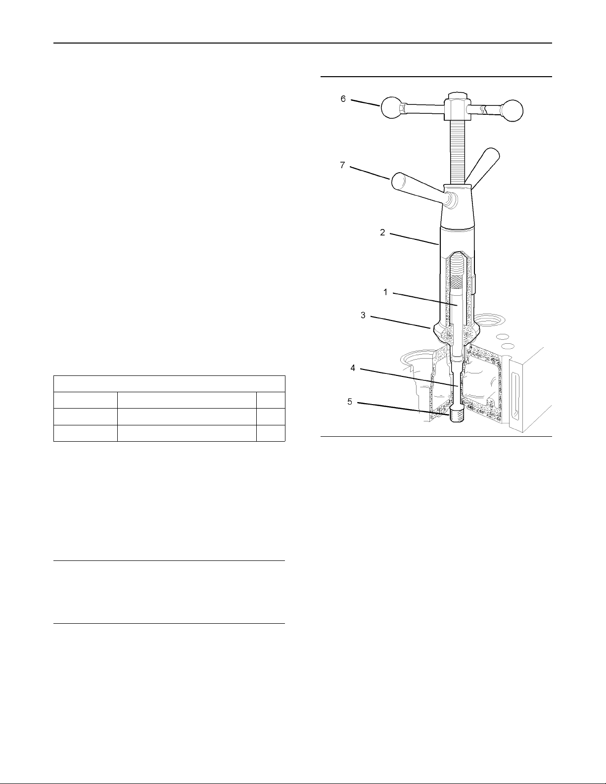
1. Install the 21825479 Valve Guide Adapter (1) into
the 21825478 Valve Guide Remover/Replacer
(2).
2. Place the spacer (3) into the appropriate valve
seat.
3. Pass the adapter (1) through the valve guide (4)
and install the valve guide remover/replacer (2)
onto the spacer (3).
4. Install the attachment (5) in order to secure the
adapter (1) to the valve guide (4).
5. Hold the top handle (6) and turn the bottom
handle (7) counterclockwise in order to push the
valve guide (4) from the cylinder head.
6. Repeat Step 2 to Step 5 in order to extract each
appropriate valve guide (4).
7. Discard all of the valve guides (4) that were
removed from the cylinder head.
Page 27
27
Disassembly and Assembly Section
Note: When new valve guides are installed, new
valves and new valve seat inserts must be installed.
8. Remove the valve seat inserts. Refer to this
Disassembly and Assembly Manual, “Inlet and
Exhaust Valve Seat Inserts - Remove and Install”.
Installation Procedure
Ta bl e 6
Required Tools
Part Number Part Description
21825478
27610234
Valve Guide Remover/Replacer
Valve Guide Adapter
NOTICE
Keep all parts clean from contaminants.
Contaminants may cause rapid wear and shortened
component life.
Qty
1
1
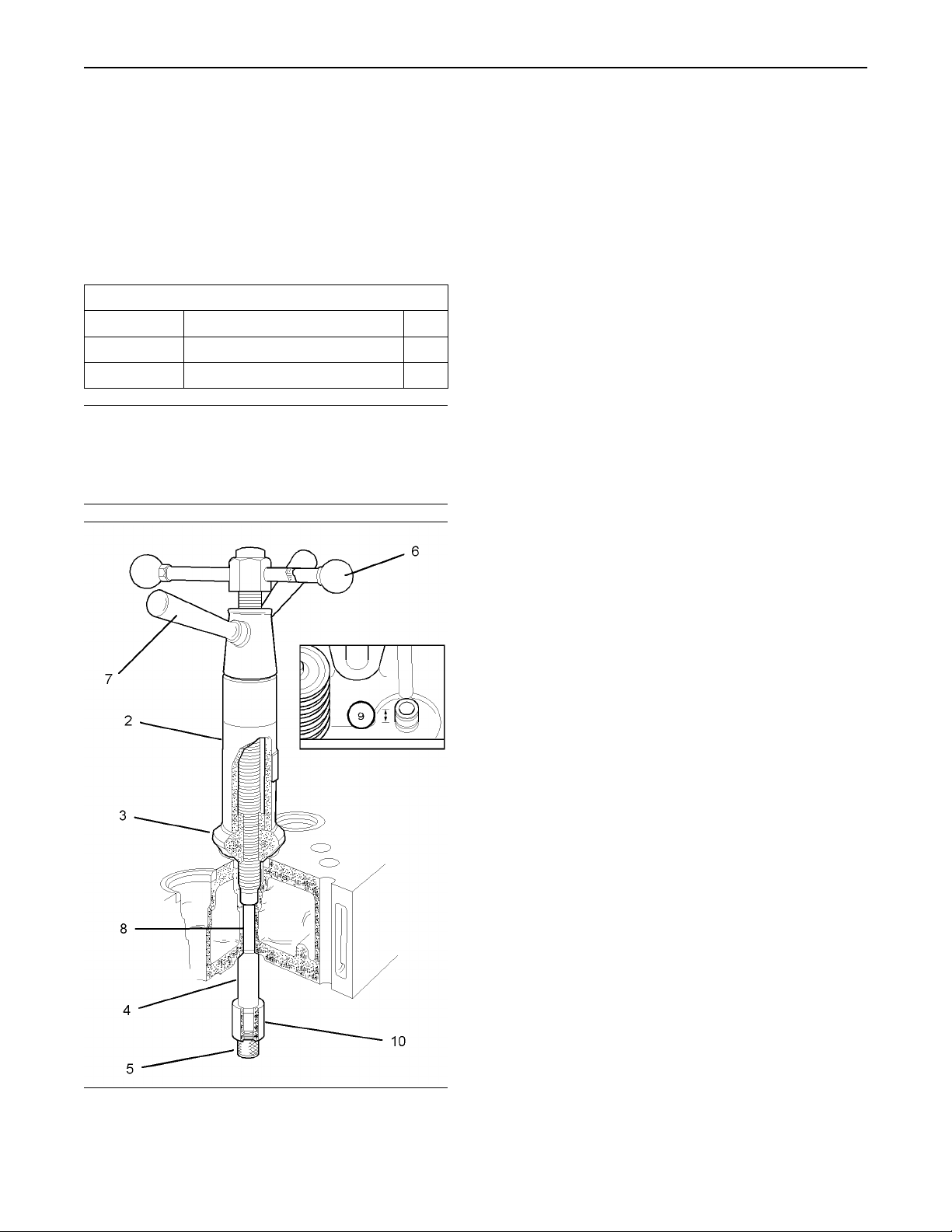
2. Install the 27610234 Valve Guide Adaptor (8) into
the 21825478 Valve Guide Remover/Replacer
(2).
3. Install the spacer (3) into the appropriate valve
seat.
4. Lubricate the outer surface of a new valve guide
(4) with clean engine lubricating oil. Pass the
adapter (8) through the parent bore for the
valve guide (4) and position the valve guide
remover/replacer (2) onto the spacer (3).
5. Install the adapter (10) beneath the valve guide
(4). Install the attachment (5) in order to secure
the adapter (10) to the valve guide (4).
Note: The valve guide (4) should protrude above
the cylinder head. Ensure that the protrusion (9) is
within limits.
6. Hold the top handle (6) and turn the bottom
handle (7) clockwise in order to pull the valve
guide (4) into the cylinder head. Continue to pull
the valve guide (4) into the cylinder head until the
correct amount of protrusion (9) is reached. The
valve guides should protrude 12.35 to 12.65 mm
(0.4862 to 0.4980 inch) above the valve spring
recess.
7. Repeat the Step 3 to Step 6 in order to install
each appropriate valve guide.
Note: The parent bores of the valve guides must be
reamed to the correct size after the valve guides
have been installed into the cylinder head. Also, the
valve inserts must be inserted and the seat faces
must be cut to the correct angle. The same tool is
used to finish both components.
8. Install the valve seat inserts and finish both
components. Refer to this Disassembly and
Assembly Manual, “Inlet and Exhaust Valve Seat
Inserts - Remove and Install”.
End By:
a. Install the inlet valves and the exhaust valves.
Refer to this Disassembly and Assembly Manual,
“Inlet and Exhaust Valves - Remove and Install”.
Illustration 48
g01016462
1. Clean the parent bores in the cylinder head for
all of the appropriate valve guides (4).
Page 28
28
Disassembly and Assembly Section
i01947654
Inlet and Exhaust Valve Seat
Inserts - Remove and Install
NOTICE
Keep all parts clean from contaminants.
Contaminants may cause rapid wear and shortened
component life.
Removal Procedure
Start By:
a. Remove the inlet valves and the exhaust valves.
Refer to this Disassembly and Assembly Manual,
“Inlet and Exhaust Valves - Remove and Install”.
NOTICE
Keep all parts clean from contaminants.
Contaminants may cause rapid wear and shortened
component life.
Note: When new valve seat inserts are installed,
new valves and new valve guides must be installed.
1. Remove the appropriate valve guides. Install
partially finished valve guides. Refer to this
Disassembly and Assembly Manual, “Inlet and
Exhaust Valve Guides - Remove and Install”.
Note: The inserts for the inlet valves are a larger
diameter than the exhaust valve inserts.
2. Use the partially finished bore of the valve guide
as a pilot bore in order to remove the valve insert
by machining. Also use the partially finished
bore of the valve guide as a pilot bore in order
to machine a recess for a new valve seat. Refer
to the Specifications Manual, “Cylinder Head
Valves” for the required dimensions of the recess
for the valve seat. Remove all debris from the
cylinder head ports and passages.
Note: If the cylinder head has been previously
ground then the bottom face of valve seat must
be ground in order to ensure that the valve seat
will be installed correctly into the cylinder head.
A 30 degree chamfer must be machined to the
outer edge of the valve seat after the back face
of the valve insert has been ground to the correct
dimensions. The 30 degree chamfer must be within
the tolerance of 0.91 mm (0.036 inch) to 1.3 mm
(0.051 inch). Also, the chamfer must be inclined to
the vertical face of the valve insert.
Note: Do not use a hammer in order to install the
valve insert into the machined recess in the cylinder
head.
Note: Do not apply any lubricant before the new
valve seat insert is installed into the cylinder head.
1. Use a suitable tool to install the valve seat insert
into the machined recess in the cylinder head.
3. Repeat the Step 2 for all of the appropriate valve
seats.
Installation Procedure
Ta bl e 7
Required Tools
Part Number Part Description
27610030
Valve Guide/Valve Seat
Reamer/Cutter
Qty
1
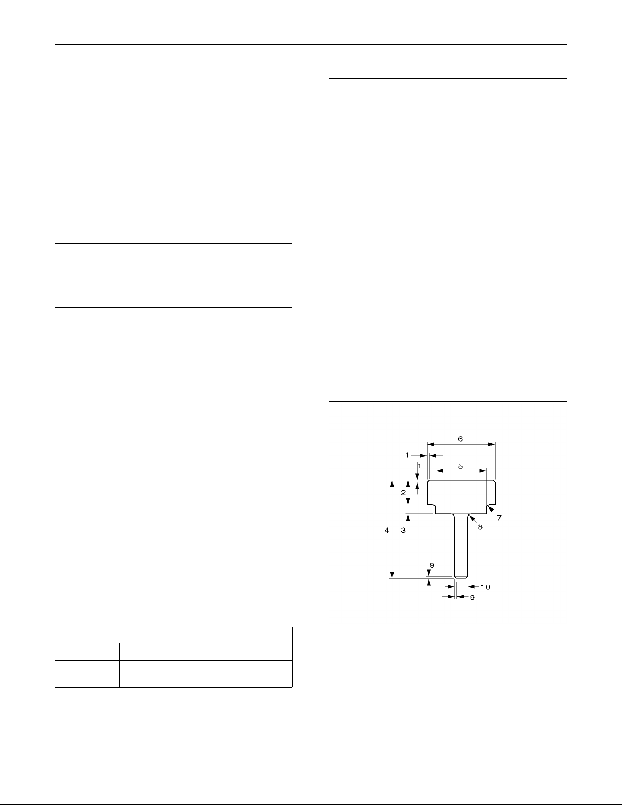
Illustration 49
2. If necessary, a suitable tool can be manufactured.
Refer to the illustration 49. Also refer to the table
8 and refer to the table 9 for suitable dimensions.
g01016768
Page 29
29
Disassembly and Assembly Section
Ta bl e 8
Callout
10
Ta bl e 9
Callout
1
2
3
4
5
6
7
8
9
10
Tool for the Inlet Valve Seat Inserts
Dimension
1
2
3
4
5
6
7
8
9
6.8 mm (0.268 inch) to 7.1 mm (0.279 inch)
38.1 mm (1.500 inch) to 38.3 mm (1.508 inch)
46.25 mm (1.82 inch) to 46.5 mm (1.83 inch)
Maximum radius 1.4 mm (0.055 inch)
Maximum radius 1.5 mm (0.06 inch)
8.77 mm (0.345 inch) to 8.80 mm (0.346 inch)
Tool for the Exhaust Valve Seat Inserts
7.2 mm (0.283 inch) to 7.5 mm (0.295 inch)
34.38 mm (1.353 inch) to 34.58 mm
41.75 mm (1.643 inch) to 42.00 mm
Maximum radius 1.4 mm (0.055 inch)
Maximum radius 1.5 mm (0.06 inch)
8.77 mm (0.345 inch) to 8.80 mm (0.346 inch)
1.5 mm (0.06 inch)
20 mm (0.80 inch)
100 mm (3.94 inch)
1.5 mm (0.06 inch)
Dimension
1.5 mm (0.06 inch)
20 mm (0.80 inch)
100 mm (3.94 inch)
(1.361 inch)
(1.653 inch)
1.5 mm (0.06 inch)
5. After installing the valve guides and valve seat
inserts, the valve guides must be reamed and
the valve seat inserts must be cut to the finished
diameter. The valve guides and valve seat
inserts are cut and reamed in one operation.
This procedure ensures the concentricity of the
valve seat to the valve guide in order to create
a good seal. Refer to the Specifications Manual,
“Cylinder Head Valves” for the finished diameter
of the valve guides and valve seat inserts.
3. Put the appropriate valve seat insert in position.
Install the special tool that was manufactured
previously, through the valve seat insert and
use the pilot bore of the valve guide in order to
center the tool and the insert into the recess.
Lightly tap the valve seat insert in order to start
the installation. Press the valve seat insert into
the recess with a suitable press. Ensure that the
bottom of the valve seat insert is against the
bottom of the recess.
4. Repeat Step 3 for the remaining valve seat
inserts.
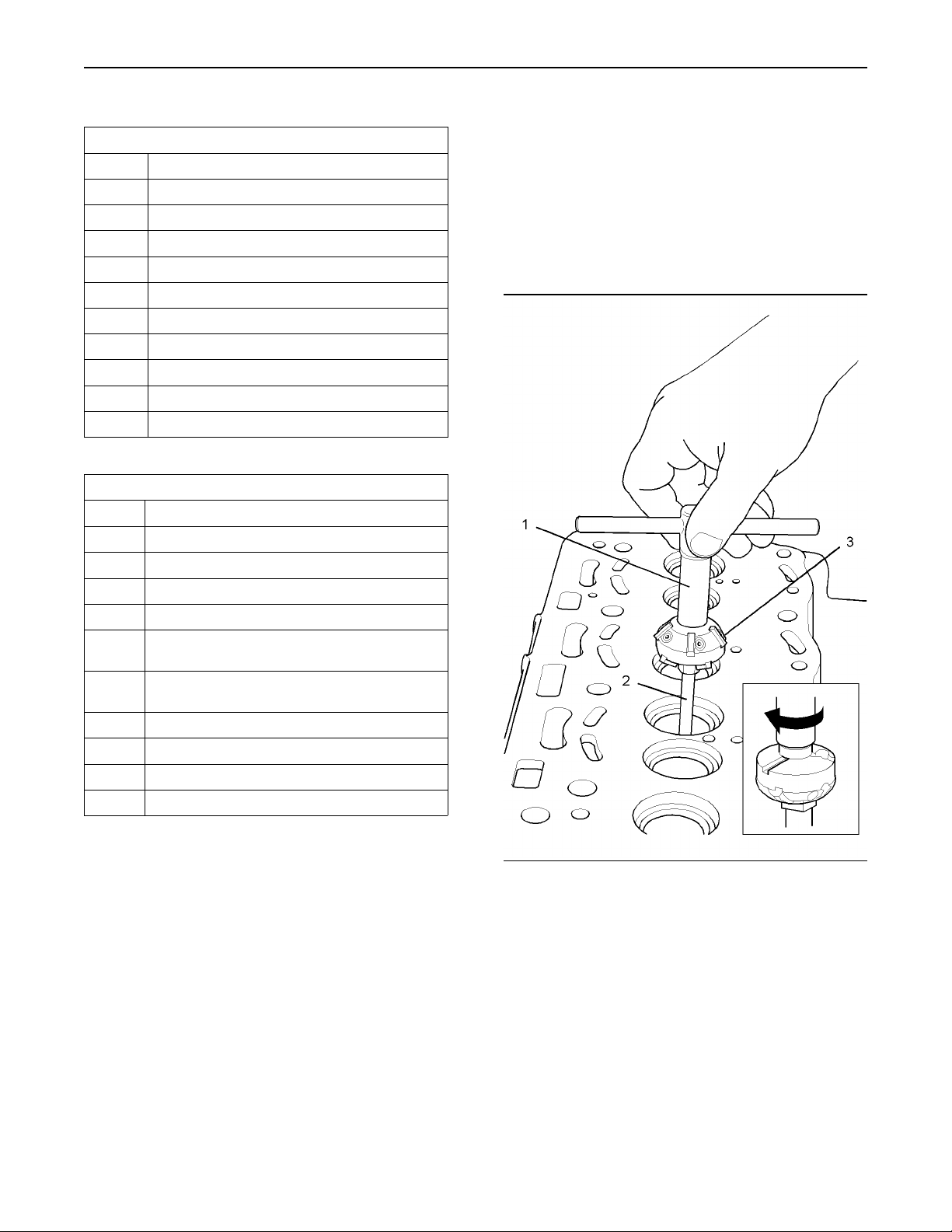
Illustration 50
g01017975
Note: Ensure that the 27610030 Valve Guide/Valve
Seat Reamer/Cutter is assembled correctly with the
correct angle of cutter (3) for the valve seat toward
the cylinder head.
Note: Ensure that the cutter (3) for the valve seat is
not allowed to contact the valve seat insert until the
valve guide has been reamed to the correct size.
Page 30
30
Disassembly and Assembly Section
6. Set the diameter of the cutter (3) to the correct
size for the valve seat to be cut. Refer to the
Specifications Manual, “Cylinder Head Valves”
for the correct diameter. Position the reamer (2)
of the tool (1) into the appropriate valve guide.
Carefully turn the handle in a clockwise direction
and gradually move the reamer (2) into the valve
guide until the valve guide is reamed to the
finished size.
7. Continue to turn the handle in a clockwise
direction in order to cut the valve seat insert.
Remove the minimum amount of material in order
to ensure a good valve seat. Keep the valve seat
as narrow as possible.
8. Remove the tool (1). Clean the debris from the
valve guide and the valve seat.
9. Repeat Step 6 to Step 8 in order to cut all of the
appropriate valve seats.
End By:
a. Install the inlet valves and the exhaust valves.
Refer to this Disassembly and Assembly Manual,
“Inlet and Exhaust Valves - Remove and Install”.
NOTICE
Care must be taken to ensure that fluids are contained
during performance of inspection, maintenance, testing, adjusting and repair of theproduct. Be prepared to
collect the fluid with suitable containers before opening any compartment or disassembling any component containing fluids.
Dispose of all fluids according to local regulations and
mandates.
1. Remove all dirt, oil, and grease from the engine
oil filter assembly and from the drain plug of
the engine oil pan. Place a suitable container
beneath the drain plug of the engine oil pan.
2. Operate the engine until the engine is warm.
Stop the engine.
3. Remove the oil drain plug and the O-ring from
the engine oil pan. Drain the engine oil into the
container for storage or disposal.
i01958098
Engine Oil Filter Base Remove and Install
Removal Procedure for an Oil Filter
with a Separate Filter Element
Note: This procedure is for the removal of an oil
filter with an oil filter housing and a separate oil
filter element.
Note: The oil filter can be installed vertically or the
oil filter can be installed horizontally.
NOTICE
Keep all parts clean from contaminants.
Contaminants may cause rapid wear and shortened
component life.
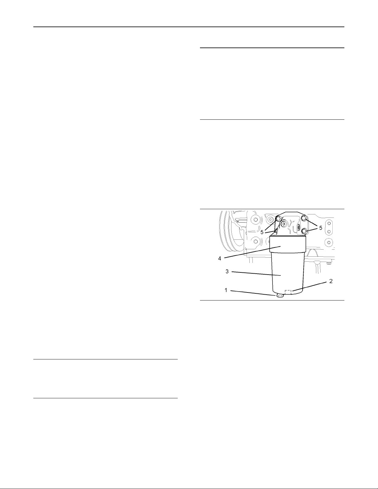
Illustration 51
Typical example
Note: The drain plug (1) in the horizontal type of oil
filter is installed in the filter head (4) instead of the
oil filter housing (3). Do not remove the drain plug
(1) from this type of oil filter.
4. Place a suitable container beneath the drain plug
(1) in the oil filter housing (3). Remove the drain
plug (1) from the oil filter housing (3) and remove
the O-ring from the drain plug (1). Discard the
O-ring. Collect any engine oil that drains from
the oil filter housing (3).
5. Install a ratchet with a 1/2 inch square drive into
the recess (2) in the base of the oil filter housing
(3) in order to remove the oil filter housing.
g01018261
Page 31

Illustration 52
Typical example
g01018307
6. Remove the oil filter element (6) from the oil filter
housing (3). Remove the O-ring (7) from the oil
filter housing (3). Discard the O-ring (7).
Note: Step 1 to Step 6 is the procedure for removing
the oil filter element. Step 6 to Step 9 is the
additional procedure for removing the oil filter base
(4).
31
Disassembly and Assembly Section
Installation Procedure for an Oil
Filter with a Separate Filter Element
NOTICE
Keep all parts clean from contaminants.
Contaminants may cause rapid wear and shortened
component life.
Note: Step 1 to Step 5 is the procedure for installing
the oil filter base if the oil filter base was previously
removed. Step 6 to Step 11 is the procedure for
installing the oil filter element.
Illustration 53
Typical example
g01018337
7. Remove the setscrews (5).
8. Remove the engine oil filter base (4) from the
cylinder block. Remove the joint (8) and discard
the joint.
9. If necessary, remove the plug (9) and the O-ring.
10. If necessary, remove the plug (10) and the
O-ring.
Illustration 54
Typical example
g01018337
1. Clean the oil passages within the oil filter base
(4). Clean the mating surfaces of the cylinder
block and the engine oil filter base (4).
2. Inspect the O-ring for the plug (10) if the plug
was removed from the oil filter base (4). If
necessary, replace the O-ring. Install the O-ring
and the plug (10) into the oil filter base (4).
Tighten the plug (10) to a torque of 12 N·m
(9 lb ft).
3. Inspect the O-ring for the plug (9) if the plug was
removed from the oil filter base (4). If necessary,
replace the O-ring. Install the O-ring and the
plug (9) into the oil filter base (4). Tighten the
plug (9) to a torque of 12 N·m (9 lb ft).
Note: New setscrews (5) have sealant on the first
13 mm (0.5 inch) of the threads. In order to reuse
the old setscrews (5), clean the old sealant from
the setscrews and apply 21820117 POWERPART
Threadlock and Nutlock to the setscrews.
Note: Do not lubricate the new joint (8).
4. Install the setscrews (5) into the oil filter base
(4). Install a new joint (8) onto the setscrews (5).
Install the setscrews (5) into the cylinder block.
Page 32

32
Disassembly and Assembly Section
5. Evenly tighten the setscrews (5). Refer to the
Torque Specifications Manual, “Standard Torque
for Metric Fasteners” for further information.
Illustration 55
Typical example
g01018307
8. Screw the oil filter housing (3) into the oil filter
base (4) by hand. Install a 1/2 inch square drive
into the recess (2) in order to tighten the oil filter
housing (3) to a torque of 25 N·m (18 lb ft).
9. Tighten the drain plug (1) to a torque of 12 N·m
(9 lb ft).
10. Inspect the O-ring for the drain plug for the
engine oil pan. If necessary, replace the O-ring.
Install the O-ring onto the drain plug for the
engine oil pan and install the drain plug into the
engine oil pan. Tighten the drain plug to the
correct torque. Refer to this Disassembly and
Assembly Manual, “Engine Oil Pan - Remove
and Install” for the correct torque. Remove the
suitable containers beneath the engine oil pan
and beneath the oil filter housing.
11. Fill the engine oil to the correct level that is
indicated on the engine oil level gauge. Refer to
the Operation and Maintenance Manual, “Refill
Capacities” for the lubrication system capacity
of the engine.
Removal Procedure for a Spin-On
Oil Filter
Illustration 56
Typical example
g01018261
6. Clean the inner surface of the oil filter housing
(3). Clean the mating surfaces of the oil filter
base (4) and the oil filter housing (3). Install a
new O-ring onto the drain plug (1) if the drain
plug was removed previously. Install the drain
plug (1) into the oil filter housing (3). Tighten the
drain plug (1) finger tight.
7. Lubricate a new O-ring (7) with clean engine
lubricating oil. Install the new O-ring (7) onto the
oil filter housing (3). Install a new oil filter element
(6) into the oil filter housing (3). Rotate the oil
filter element (6) in order to lock the element in
the oil filter housing (3).
Note: Add clean engine lubricating oil into the oil
filter housing (3) if the oil filter is installed vertically
on the engine. Allow sufficient time for the added oil
to flow through the oil filter element (6).
Note: This procedure is for the removal of an oil filter
with an oil filter element that has an integral housing.
Note: The oil filter can be installed vertically or the
oil filter can be installed horizontally.
NOTICE
Keep all parts clean from contaminants.
Contaminants may cause rapid wear and shortened
component life.
NOTICE
Care must be taken to ensure that fluids are contained
during performance of inspection, maintenance, testing, adjusting and repair of theproduct. Be prepared to
collect the fluid with suitable containers before opening any compartment or disassembling any component containing fluids.
Dispose of all fluids according to local regulations and
mandates.
1. Remove all dirt, oil, and grease from the engine
oil filter assembly and from the drain plug of
the engine oil pan. Place a suitable container
beneath the drain plug of the engine oil pan.
2. Operate the engine until the engine is warm.
Stop the engine.
Page 33

3. Remove the oil drain plug and the O-ring from
the engine oil pan. Drain the engine oil into the
container for storage or disposal.
33
Disassembly and Assembly Section
Illustration 57
Typical example
g01018706
4. Place a suitable container beneath the oil filter
element (11).
5. Use a suitable strap wrench in order to remove
the oil filter element (11). Discard the oil filter
element (11) in a suitable manner.
Note: Step 1 to Step 5 is the procedure for removing
the oil filter element (11). Step 6 to Step 9 is the
additional procedure for removing the oil filter base
(12).
6. Remove the setscrews (13).
7. Remove the engine oil filter base (12) from the
cylinder block. Remove the joint (14) and discard
the joint.
8. If necessary, remove the adapter (15) from the
oil filter base (12).
9. If necessary, remove the plug (16) and the
O-ring.
10. If necessary, remove the plug (17) and the
O-ring.
Installation Procedure for a Spin-On
Oil Filter
Illustration 58
Typical example
g01018706
1. Clean the oil passages within the oil filter base
(12). Clean the mating surfaces of the cylinder
block and the engine oil filter base (12).
2. Inspect the adapter (15) if the adapter was
removed from the oil filter base (12). Install
the adapter (15) into the oil filter base (12).
Tighten the adapter (15). Refer to the Torque
Specifications Manual, “Standard Torque for
O-Ring Face Seal Fittings and 37 Degree Flared
Fittings” for the correct torque.
3. Inspect the O-ring for the plug (17) if the plug
was removed from the oil filter base (12). If
necessary, replace the O-ring. Install the O-ring
and the plug (17) into the oil filter base (12).
Tighten the plug (17) to a torque of 12 N·m
(9 lb ft).
4. Inspect the O-ring for the plug (16) if the plug
was removed from the oil filter base (12). If
necessary, replace the O-ring. Install the O-ring
and the plug (16) into the oil filter base (12).
Tighten the plug (16) to a torque of 12 N·m
(9 lb ft).
Note: New setscrews (13) have sealant on the first
13 mm (0.5 inch) of the threads. In order to reuse
the old setscrews (13), clean the old sealant from
the setscrews and apply 21820117 POWERPART
Threadlock and Nutlock to the setscrews.
Note: Do not lubricate the new joint (14).
NOTICE
Keep all parts clean from contaminants.
Contaminants may cause rapid wear and shortened
component life.
Note: Step 1 to Step 6 is the procedure for installing
the oil filter base if the oil filter base was previously
removed. Step 7 to Step 10 is the procedure for
installing the oil filter element.
5. Install the setscrews (13) into the oil filter base
(12). Install a new joint (14) onto the setscrews
(13). Install the setscrews (13) into the cylinder
block.
6. Evenly tighten the setscrews (13). Refer to the
Torque Specifications Manual, “Standard Torque
for Metric Fasteners” for further information.
7. Clean the mating surface of the oil filter base
(12) to the oil filter element (11).
Page 34

34
Disassembly and Assembly Section
NOTICE
Care must be taken to ensure that fluids are contained
during performance of inspection, maintenance, testing, adjusting and repair of theproduct. Be prepared to
collect the fluid with suitable containers before opening any compartment or disassembling any component containing fluids.
Dispose of all fluids according to local regulations and
mandates.
Illustration 59
8. Lubricate the top of the O-ring (18) with clean
engine lubricating oil. Spin the new oil filter
element (11) onto the adapter (15). Tighten the
oil filter element (11) by hand. Do not use a strap
wrench to tighten the oil filter element (11).
9. Inspect the O-ring for the drain plug for the
engine oil pan. If necessary, replace the O-ring.
Install the O-ring onto the drain plug for the
engine oil pan and install the drain plug into the
engine oil pan. Tighten the drain plug to the
correct torque. Refer to this Disassembly and
Assembly Manual, “Engine Oil Pan - Remove
and Install” for the correct torque. Remove the
suitable containers beneath the engine oil pan
and beneath the oil filter housing.
10. Fill the engine oil to the correct level that is
indicated on the engine oil level gauge. Refer to
the Operation and Maintenance Manual, “Refill
Capacities” for the lubrication system capacity
of the engine.
g01018743
i01958099
Illustration 60
g01041195
Engine Oil Cooler - Remove
Removal Procedure for Three
Cylinder Engine
NOTICE
Keep all parts clean from contaminants.
Contaminants may cause rapid wear and shortened
component life.
Page 35

35
Disassembly and Assembly Section
NOTICE
Care must be taken to ensure that fluids are contained
during performance of inspection, maintenance, testing, adjusting and repair of theproduct. Be prepared to
collect the fluid with suitable containers before opening any compartment or disassembling any component containing fluids.
Dispose of all fluids according to local regulations and
mandates.
1. Drain the coolant from the engine into a suitable
container. Drain the engine oil from the engine
into a suitable container. Refer to the Operation
and Maintenance Manual for the procedure on
draining the engine coolant and the engine oil.
Illustration 61
g01041194
1. Drain the coolant from the engine into a suitable
container. Drain the engine oil from the engine
into a suitable container. Refer to the Operation
and Maintenance Manual for the procedure on
draining the engine coolant and the engine oil.
2. Remove the hose clamp and the hose from the
coolant inlet (1). Remove the hose clamp and
the hose from the coolant outlet (2).
3. Remove the adapter (3) from the oil cooler body
(4).
4. Remove the O-rings (5), (6), and (7). Discard the
O-rings (5), (6), and (7).
5. If necessary, remove the setscrews (8) in order to
remove the oil cooler base (9) from the cylinder
block. Remove the joint from the cylinder block.
Discard the joint.
Removal Procedure for Four
Cylinder Engine
Illustration 62
g00952614
Note: Do not remove the setscrews (7) at this time.
2. Remove the setscrews (6). Remove the setscrews
(4).
3. Remove the housing (3) from the cylinder block.
4. Remove the setscrews (7). Remove the engine
oil cooler (2) and the seals (5) from the housing
(3). Discard the seals (5).
5. Remove the joint (1) from the cylinder block.
Discard the joint (1).
NOTICE
Keep all parts clean from contaminants.
Contaminants may cause rapid wear and shortened
component life.
Page 36

36
Disassembly and Assembly Section
i01958100
Engine Oil Cooler - Install
Installation Procedure for the Three
Cylinder Engine
NOTICE
Keep all parts clean from contaminants.
Contaminants may cause rapid wear and shortened
component life.
Illustration 63
g01041195
1. Clean the mating surfaces of the oil cooler base
(9) and the oil cooler body (4). If the oil cooler
base (9) was removed, clean the mating surfaces
of the oil cooler base and the cylinder block.
Illustration 64
Tightening sequence
g01041030
Note: Do not use sealant on the new joint between
the cylinder block and the oil cooler base (9).
2. If the oil cooler base (9) was removed from the
cylinder block, install setscrews into setscrew
holes (1) and (6) in the oil cooler base. Install a
new joint onto the two setscrews and secure the
oil cooler base (9) to the cylinder block. Install
the remainder of the setscrews (8). Tighten the
setscrews (8) in the sequence 1, 2, 3, 4, 5, and
6 to a torque of 22 N·m (16 lb ft). Refer to the
illustration 64.
Page 37

37
Disassembly and Assembly Section
Illustration 65
3. Install new O-rings (7) and (8) onto the oil cooler
body (4). Position the oil cooler body (4) onto
the oil cooler base (9).
4. Install a new O-ring (7) onto the adapter (3).
Install the adapter (3) through the oil cooler body
(4) and into the oil cooler base (9). Tighten the
adapter (3) to a torque of 57 N·m (42 lb ft).
5. Install the appropriate hose to the coolant outlet
(2). Tighten the hose clamp to a torque of
3.5 N·m (31 lb in).
6. Install the appropriate hose to the coolant inlet
(1). Tighten the hose clamp to a torque of
3.5 N·m (31 lb in).
g01041194
Illustration 66
1. Clean the mating surfaces of the housing (3) and
the cylinder block.
2. Position the engine oil cooler (2) and the new
seals (5) in the housing (3). Install the setscrews
(7) in order to secure the engine oil cooler (2)
to the housing (3).
Note: Do not use sealant on the joint (1).
3. Position the housing (3) and the new joint (1)
onto the cylinder block. Install the setscrews (4)
and the setscrews (6) in order to secure the
housing (3) to the cylinder block.
4. Tighten all of the setscrews (4, 6 and 7) to the
correct torque. Refer to the Torque specifications
Manual, “Standard Torques for Metric Fasteners”
for further information.
Note: Refer to the Operation and Maintenance
Manual, “Refill Capacities” for the cooling system
capacity and for the lubrication system capacity
of the engine.
5. Fill the cooling system with coolant. Fill the
lubrication system with engine oil.
g00952614
i01958106
7. Fill the cooling system with coolant. Fill the
lubrication system with engine oil. Refer to the
Operation and Maintenance Manual, “Refill
Capacities” for the cooling system capacity and
for the lubrication system capacity of the engine.
Installation Procedure for the Four
Cylinder Engine
NOTICE
Keep all parts clean from contaminants.
Contaminants may cause rapid wear and shortened
component life.
Engine Oil Relief Valve Remove and Install
(Engine Oil Pump)
Removal Procedure
Start By:
a. Remove the engine oil pan. Refer to this
Disassembly and Assembly Manual, “Engine Oil
Pan - Remove and Install”.
Page 38

38
Disassembly and Assembly Section
NOTICE
Keep all parts clean from contaminants.
Contaminants may cause rapid wear and shortened
component life.
Illustration 67
g00959674
Personal injury can result from being struck by
parts propelled by a released spring force.
Make sure to wear all necessary protective equipment.
Follow the recommended procedure and use all
recommended tooling to release the spring force.
1. Remove the plug (2). Remove the spring (3) and
the plunger (4) from the engine oil pump (1).
Installation Procedure
Illustration 68
g00959674
Improper assembly of parts that are spring loaded
can cause bodily injury.
To prevent possible injury, follow the established
assembly procedure and wear protective equipment.
2. Install the plunger (4) and the spring (3) in the
engine oil pump (1).
3. Install the plug (2). Tighten the plug (2) to a
torque of 22 N·m (16 lb ft).
End By:
a. Install the engine oil pan. Refer to this
Disassembly and Assembly Manual, “Engine Oil
Pan - Remove and Install”.
NOTICE
Keep all parts clean from contaminants.
Contaminants may cause rapid wear and shortened
component life.
1. Clean the spring (3) and the plunger (4) of the
engine oil relief valve. Check the spring (3) and
the plunger (4) for wear or for other damage.
The plunger (4) must slide easily within the bore
of the oil relief valve within the engine oil pump
(1). Lubricate the spring (3) and the plunger (4)
with clean engine oil.
Page 39

39
Disassembly and Assembly Section
Engine Oil Relief Valve Remove and Install
(Balancer Unit for the 1104
engines only)
Removal Procedure
Start By:
a. Remove the engine oil pan. Refer to this
Disassembly and Assembly Manual, “Engine Oil
Pan - Remove and Install”.
NOTICE
Keep all parts clean from contaminants.
i01958108
Installation Procedure
NOTICE
Keep all parts clean from contaminants.
Contaminants may cause rapid wear and shortened
component life.
1. Clean the spring (3) and the plunger (4) of the
engine oil relief valve. Check the spring (3) and
the plunger (4) for wear or for other damage.
The plunger (4) must slide easily within the bore
of the oil relief valve within the balancer unit (1).
Lubricate the spring (3) and the plunger (4) with
clean engine oil.
Contaminants may cause rapid wear and shortened
component life.
Illustration 69
Personal injury can result from being struck by
parts propelled by a released spring force.
Make sure to wear all necessary protective equipment.
g00979780
Illustration 70
Improper assembly of parts that are spring loaded
can cause bodily injury.
To prevent possible injury, follow the established
assembly procedure and wear protective equipment.
2. Install the plunger (4) and the spring (3) into the
balancer unit (1).
3. Install the plug (2). Tighten the plug (2) to a
torque of 22 N·m (16 lb ft).
End By:
a. Install the engine oil pan. Refer to this
Disassembly and Assembly Manual, “Engine Oil
Pan - Remove and Install”.
g00979780
Follow the recommended procedure and use all
recommended tooling to release the spring force.
1. Remove the plug (2). Remove the spring (3) and
the plunger (4) from the balancer unit (1).
Page 40

40
Disassembly and Assembly Section
i01958101
Engine Oil Pump - Remove
(Engines Without a Balancer)
Removal Procedure
Start By:
a. Remove the engine oil pan. Refer to this
Disassembly and Assembly Manual, “Engine Oil
Pan - Remove and Install”.
Note: This procedure is for the removal of the engine
oil pump on engines that are not equipped with a
balancer. Refer to this Disassembly and Assembly
Manual, “Balancer Group - Remove” for information
on the removal of the engine oil pump on engines
that are equipped with a balancer.
NOTICE
Keep all parts clean from contaminants.
Contaminants may cause rapid wear and shortened
component life.
2. Remove the setscrews (3). Remove the assembly
of the engine oil pump (4) from the cylinder
block.
3. If necessary, remove the pressure relief valve (5)
from the assembly of the engine oil pump (4).
Refer to this Disassembly and Assembly Manual,
“Engine Oil Relief Vave - Remove and Install”.
Illustration 72
4. Remove the setscrews (6). Remove the engine
oil pump (7) from the assembly of the engine
oil pump (4).
g01019047
NOTICE
Care must be taken to ensure that fluids are contained
during performance of inspection, maintenance, testing, adjusting and repair of theproduct. Be prepared to
collect the fluid with suitable containers before opening any compartment or disassembling any component containing fluids.
Dispose of all fluids according to local regulations and
mandates.
Illustration 71
1. Remove the setscrews (1) and the suction pipe
(2).
g01019045
5. If necessary, remove the setscrews and remove
the front cover assembly from the engine oil
pump (7) in order to inspect the components
within the engine oil pump.
i01958102
Engine Oil Pump - Install
(Engines Without a Balancer)
Installation Procedure
Note: This procedure is for the installation of the
engine oil pump on engines that are not equipped
with a balancer. Refer to this Disassembly and
Assembly Manual, “Balancer Group - Install” for
information on the installation of the engine oil pump
on engines that are equipped with a balancer.
NOTICE
Keep all parts clean from contaminants.
Contaminants may cause rapid wear and shortened
component life.
Page 41

NOTICE
If any of the parts on the engine oil pump are worn or
damaged, the entire pump must be replaced.
1. Clean all of the internal components of the
oil pump if the front cover of the oil pump
was previously removed in order to inspect
the internal components. Check the internal
components for wear and for other damage.
Check the clearance between the outer rotor
of the oil pump and the oil pump body. Check
the clearance between the outer rotor and the
inner rotor. Check the end play movement of
the rotor. Refer to the Systems Operation/Testing
and Adjusting Manual, “Engine Oil Pump Inspect”. Replace the engine oil pump if any of
the components are worn or damaged.
2. Lubricate the inner rotor and the outer rotor of the
engine oil pump with clean engine lubricating oil.
Install the front cover of the engine oil pump onto
the body of the oil pump. Install the setscrews
and tighten the setscrews in order to secure the
front cover to the body.
Disassembly and Assembly Section
Illustration 74
g01019045
8. If the pressure relief valve (5) was removed,
install the pressure relief valve. Refer to this
Disassembly and Assembly Manual, “Engine Oil
Relief Valve - Remove and Install” for further
information.
9. Position the suction pipe (2) and install the
setscrews (1).
End By:
41
Illustration 73
g01019312
3. Fill engine oil pump (6) with clean engine oil.
4. Install the engine oil pump (6) into the assembly
of the engine oil pump (4). Install the setscrews
(7). Tighten the setscrews to a torque of 9 N·m
(80 lb in).
5. Ensure that the dowel pin (8) and the hollow
dowel (9) are correctly located in the cylinder
block. Install the assembly of the engine oil
pump (4) onto the dowels (8 and 9).
6. Install the setscrews (3). Tighten the setscrews
to a torque of 44 N·m (32 lb ft).
7. Check the backlash between the idler gear (10)
of the oil pump and the crankshaft gear. Refer to
the Specifications Manual, “Gear Group - Front”
for further information.
a. Install the engine oil pan. Refer to this
Disassembly and Assembly Manual, “Engine Oil
Pan - Remove and Install”.
i01991657
Water Pump - Remove
Removal Procedure
Start By:
a. Remove the fan. Refer to this Disassembly and
Assembly Manual, “Fan - Remove and Install”.
NOTICE
Keep all parts clean from contaminants.
Contaminants may cause rapid wear and shortened
component life.
NOTICE
Care must be taken to ensure that fluids are contained
during performance of inspection, maintenance, testing, adjusting and repair of theproduct. Be prepared to
collect the fluid with suitable containers before opening any compartment or disassembling any component containing fluids.
Dispose of all fluids according to local regulations and
mandates.
Page 42

42
Disassembly and Assembly Section
1. Drain the coolant from the cooling system into a
suitable container for storage or disposal.
2. Loosen the clamps and remove the hose from
the water pump inlet.
Illustration 75
g00952695
3. Remove the setscrews (3) that fasten the water
pump (4) to the front housing (1).
4. If necessary, gently tap the water pump (4) with
a soft hammer in order to loosen the water pump.
5. Remove the water pump (4). Remove the joint (2)
from the front housing (1) and the water pump
(4). Discard the joint (1).
i01962207
Water Pump - Disassemble
Disassembly Procedure
Start By:
a. Remove the water pump. Refer to this
Disassembly and Assembly Manual, “Water
Pump - Remove and Install”.
NOTICE
Keep all parts clean from contaminants.
Illustration 76
g01019550
1. Remove the setscrews (1) from the cover (2) of
the water pump (3). Remove the joint between
the cover (2) and the water pump (3). Discard
the joint.
Note: All of the other setscrews are removed during
the removal of the water pump.
Illustration 77
g01019566
2. Drill twelve 6.35 mm (0.25 inch) holes between
the existing holes in the impeller (4). Break
pieces from the impeller (4) in order to install a
suitable puller (5) with two legs onto the impeller.
Remove the impeller (4) with the suitable puller
(5).
Contaminants may cause rapid wear and shortened
component life.
Page 43

43
Disassembly and Assembly Section
5. Support the machined face (10) of the housing
of the water pump (3) on a suitable support.
Press on the shaft (7) until the gear (11) and the
bearing (12) are free from the shaft. Discard the
shaft (7) and the bearing (12). Remove the gear
(11) through the side of the housing of the water
pump (3).
6. Support the machined face (13) of the housing of
the water pump (3) on a suitable support. Insert
a suitable mandrel on the oil seal (14) and press
the oil seal out of the housing of the water pump
(3). The oil seal (14) can be removed through the
side of the housing of the water pump (3) after
the seal has been released from the housing.
Discard the oil seal (14).
7. Use a suitable mandrel to press the needle
bearing (15) out of the housing of the water
pump (3). Discard the needle bearing (15).
i01962206
Illustration 78
g01020061
Note: It will be necessary to break the coolant seal
(6) in order to remove the coolant seal from the
water pump (3).
3. Drill three 3.175 mm (0.125 inch) holes that
are equally spaced into the coolant seal (6).
The holes should be drilled into the face of
the coolant seal (6) that would have faced the
impeller (4). Insert three 25.4 mm (1.00 inch)
long self-tapping screws into the drilled holes.
Insert a suitable lever into the coolant inlet of the
water pump (3). Use the suitable lever under the
self-tapping screws in order to evenly pull the
coolant seal (6) off the shaft (7). If necessary,
remove the center sleeve of the coolant seal from
the shaft with a suitable extractor.
Water Pump - Assemble
Assembly Procedure
NOTICE
Keep all parts clean from contaminants.
Contaminants may cause rapid wear and shortened
component life.
Illustration 79
g01019550
4. Remove the outer circlip (8) and discard the
outer circlip. Remove the inner circlip (9) and
discard the inner circlip.
Page 44

44
Disassembly and Assembly Section
5. Use a suitable adapter in order to press the
bearing (12) against the shoulder of the recess
for the bearing.
6. Install a new circlip (8) into the recess with the
housing for the water pump (3). Install a new
circlip (9) into the recess in the shaft (7). Ensure
that both circlips (8 and 9) are installed correctly.
7. Support the machined face (10) of the housing
of the water pump (3) on a suitable support.
Press the needle bearing (15) into the housing
for the bearing. Continue to press the needle
bearing (15) into the housing until the needle
bearing is either level with the top face of the
housing or the needle bearing is no more than
a maximum of 0.5 mm (0.020 inch) below the
top face of the housing.
8. Support the machined face (13) of the housing
of the water pump (3) on a suitable support.
Note: Avoid hand contact with the coolant seal (6).
The coolant seal (6) must not be contaminated by
oil or grease. The coolant seal (6) must only be
touched and/or held at the edge of the outer flange.
Illustration 80
g01020061
1. Thoroughly clean the inside of the housing of the
water pump (3). Ensure that the bores for the
bearings (12 and 15) and the coolant seal (6)
are clean and free from corrosion.
2. Inspect the gear (11) for wear and/or damage. If
necessary, replace the gear (11).
3. Support the machined face (13) of the housing of
the water pump (3). Use a suitable mandrel and
a suitable press to press a new oil seal (14) into
the housing of the water pump (3). Stop pressing
the oil seal (14) into the housing when the lower
face of the oil seal is level with the lower face of
the recess for the oil seal.
4. Install the gear (11) through the side of the
housing for the water pump (3). Use a suitable
adapter to press the shaft (7) through the oil seal
(14) and into the gear (11). Continue to press the
shaft (7) into the gear (11) until there is a gap of
1.5 mm (0.060 inch) between the gear and the
top of the housing for the gear within the housing
of the water pump (3).
Note: Do not lubricate the coolant seal (6).
Illustration 81
g01019850
9. Manufacture a suitable tool in order to press
the new coolant seal (6) into position. The tool
should be made to the dimensions shown in the
illustration 81 and the table 10.
Page 45

45
Disassembly and Assembly Section
Ta bl e 1 0
Dimensions
F
G
44.0 mm
(1.732 inch)
18.0 mm
(0.709 inch)
54.0 mm
(2.126 inch)
A 54.0 mm (2.126 inch) E
B
6.0 mm (0.236 inch)
10.0 mm (0.394 inch)
C
D
48.0 mm (1.890 inch)
10. Install the new coolant seal (6) onto the shaft
(7) with the largest diameter of the coolant seal
toward the bearing (12). Push the coolant seal
(6) onto the shaft (7) until the coolant seal is in
contact with the counterbore for the coolant seal.
Ensure that the coolant seal (6) is square with
the counterbore. Use a suitable adapter in order
to press the coolant seal (6) into the counterbore
until the outer flange of the coolant seal is in
contact with the body of the water pump (3).
Maintain the pressure on the coolant seal (10)
for about 10 seconds in order to ensure that the
coolant seal remains in position.
2. Clean the joint faces of the water pump (4) and
the front housing (1).
Illustration 82
g01019549
3. Install two guide studs (5) into the front housing
(1).
Note: Do not use sealant on the new joint (2) for
the water pump (4).
4. Install the new joint (2) onto the front housing (1).
11. Press the impeller (4) onto the shaft (7) until the
top of the impeller is level with the top of the
shaft.
12. Install a new joint for the cover (2) to the body
of the water pump (3). Install the cover (2) to
the water pump (3).
13. Install the setscrews (1). Torque the setscrews
(1) to a torque of 22 N·m (16 lb ft).
End By:
a. Install the water pump. Refer to this Disassembly
and Assembly Manual, “Water Pump - Remove
and Install”.
i01991661
Water Pump - Install
Installation Procedure
NOTICE
Keep all parts clean from contaminants.
5. Install the water pump (4) onto the front housing
(1).
Note: New setscrews have sealant to the first 13 mm
(0.5 inch) of the threads. In order to reuse the old
setscrews, clean the old sealant from the setscrews
and apply 21820117 POWERPART Threadlock and
Nutlock to the setscrews (3).
6. Install the setscrews (3) that fasten the water
pump (4) to the front housing (1). Do not tighten
the setscrews (3) at this time.
7. Remove the guide studs (5) and install the
remaining setscrews (3).
Contaminants may cause rapid wear and shortened
component life.
1. Inspect the drive gear for the water pump (4)
for wear or other damage. If necessary, replace
the drive gear.
Illustration 83
g00952731
Note: Tighten the setscrews (3) evenly in order to
pull the water pump (4) into the front housing (1).
Page 46

46
Disassembly and Assembly Section
8. Tighten the setscrews (3) in the sequence that is
shown in the illustration 83 to a torque of 22 N·m
(16 lb ft).
9. Install the hose to the water pump inlet. Tighten
the hose clamps.
10. Fill the cooling system with coolant. Refer to
the Operation and Maintenance Manual, “Refill
Capacities” for the cooling system capacity.
End By:
a. Install the fan. Refer to this Disassembly and
Assembly Manual, “Fan - Remove and Install”.
Illustration 84
g01019333
i01961880
Water Temperature Regulator Remove and Install
Removal Procedure
Ta bl e 1 1
Required Tools
Part Number Part Description
27610226
Thermostat Tool
NOTICE
Keep all parts clean from contaminants.
Contaminants may cause rapid wear and shortened
component life.
NOTICE
Care must be taken to ensure that fluids are contained
during performance of inspection, maintenance, testing, adjusting and repair of theproduct. Be prepared to
collect the fluid with suitable containers before opening any compartment or disassembling any component containing fluids.
Qty
1
2. Loosen the hose clamps from the upper radiator
hose and remove the upper radiator hose from
the water temperature regulator housing (1).
3. Remove the setscrews (2) that hold water
temperature regulator housing (1) in position on
the cylinder head. Remove the water temperature
regulator housing (1). Remove the O-ring from
the water temperature regulator housing (1).
Discard the O-ring.
Illustration 85
g01019344
Dispose of all fluids according to local regulations and
mandates.
1. Drain the coolant from the cooling system to a
level below the water temperature regulator into
a suitable container for storage or disposal.
Illustration 86
g01019356
Page 47

4. Install the 27610226 Thermostat Tool (5) into
the water temperature regulator housing (1).
Press on the tool (5) in order to squeeze the
retainers (4). Rotate the tool (5) in order to
release the water temperature regulator (3) from
the tabs (6) of the water temperature regulator
housing (1). Remove the tool (5) from the water
temperature regulator housing (1). Remove the
water temperature regulator (3) from the water
temperature regulator housing (1).
5. Refer to the Systems Operation/Testing and
Adjusting Manual, “Water Temperature Regulator
- Test” for the correct procedure on testing
the water temperature regulator. If necessary,
replace the water temperature regulator (3).
Illustration 88
47
Disassembly and Assembly Section
g01019377
Installation Procedure
Ta bl e 1 2
Required Tools
Part Number Part
27610226
Description
Thermostat Tool
NOTICE
Keep all parts clean from contaminants.
Contaminants may cause rapid wear and shortened
component life.
Qty
1
1. Clean the water temperature regulator housing
(1). Ensure that the tabs (6) for the retainers (4)
are clean. Ensure that the seat for the O-ring (7)
is clean.
Illustration 89
g01019381
2. The water temperature regulator (3) has two
vents (8) that are opened and closed by a valve
pin. These two vents (8) bleed hot water and/or
air through the water temperature regulator (3)
when the water temperature regulator is in the
closed position. Ensure that the valve pins (8)
can move freely in the vents.
Illustration 87
g01019333
3. Lubricate the new O-ring (7) with 21820221
POWERPART Red Rubber Grease. Install the
O-ring (7) into the appropriate groove in the
water temperature regulator housing (1).
Page 48

48
Disassembly and Assembly Section
Illustration 90
g01019344
8. Fill the cooling system to the proper level. Refer
to the Operation and Maintenance Manual, “Refill
Capacities” for further information.
i01963611
Flywheel - Remove
Removal Procedure
NOTICE
Keep all parts clean from contaminants.
Contaminants may cause rapid wear and shortened
component life.
Illustration 91
g01019356
4. Position the water temperature regulator (3) in
the water temperature regulator housing (1).
Install the 27610226 Thermostat Tool (5) in order
to squeeze the retainers (4). Rotate the tool (5) in
order to secure the water temperature regulator
(3) into the water temperature regulator housing
(1).
Note: The retainers (4) must be inserted behind the
tabs of the water temperature regulator housing (1)
in order to secure the water temperature regulator
(3) during engine operation.
5. Ensure that the retainers (4) are correctly installed
within the tabs (6). Position the water temperature
regulator housing (1) onto the cylinder head.
6. Install the setscrews (2) that fasten the water
temperature regulator housing (1) to the cylinder
head. Tighten the setscrews (2) to the correct
torque. Refer to the Torque Specifications
Manual, “Standard Torques for Metric Fasteners”
for further information.
7. Install the upper radiator hose and tighten the
hose clamps. Refer to the Torque Specifications
Manual for the correct torque.
Illustration 92
1. Remove the two setscrews (1).
Illustration 93
Typical example
g00905926
g01020091
Page 49

49
Disassembly and Assembly Section
2. Install two suitable studs (2) as guides.
Note: The flywheel (3) is heavy. Use suitable lifting
equipment to support the flywheel (3) before the
remainder of the setscrews (1) are removed.
3. Remove the remaining setscrews (1) that secure
flywheel (3) to the crankshaft.
Illustration 94
g01020099
4. Check the condition of the ring gear (4). Remove
the ring gear (4) if the ring gear is worn or
damaged.
Note: Identify the orientation of the ring gear on
the flywheel and the position of the chamfer on the
teeth for the correct positioning when the new ring
gear is installed.
1. Thoroughly clean the flywheel housing. Inspect
the crankshaft rear seal for leaks. If there are any
oil leaks refer to this Disassembly and Assembly
Manual, “Crankshaft Rear Seal - Remove”.
Illustration 95
g01020131
Note: If the ring gear (4) has been removed from
the flywheel (3), identify the orientation of the new
ring gear in order to install the ring gear correctly
onto the flywheel.
Note: Do not use a torch to heat the ring gear (4).
2. Heat the ring gear (4) to 250
C (480
F) in an
oven in order to install the ring gear onto the
flywheel (3). Ensure that the orientation of the
ring gear (4) is correct and quickly install the
ring gear onto the flywheel (3).
5. Place the flywheel (3) and the ring gear (4) on
a suitable support. Use a hammer and a chisel
in order to remove the ring gear (4) from the
flywheel (3).
i01963621
Flywheel - Install
Installation Procedure
NOTICE
Keep all parts clean from contaminants.
Contaminants may cause rapid wear and shortened
component life.
Always wear protective gloves when handling
parts that have been heated.
3. Clean the flywheel (3) and the ring gear (4) when
the ring gear has cooled.
Illustration 96
g01020091
4. Ensure that the guide studs (2) are still installed
in the crankshaft.
Note: The flywheel (3) is heavy. Use suitable
lifting equipment to support the flywheel until the
setscrews (1) have been installed.
5. Install the flywheel (3) onto the two guide studs
(2).
Page 50

50
Disassembly and Assembly Section
NOTICE
Care must be taken to ensure that fluids are contained
during performance of inspection, maintenance, testing, adjusting and repair of theproduct. Be prepared to
collect the fluid with suitable containers before opening any compartment or disassembling any component containing fluids.
Dispose of all fluids according to local regulations and
mandates.
Illustration 97
6. Install most of the setscrews (1) finger tight.
Remove the guide studs (2). Install the remainder
of the setscrews (1).
7. Tighten the setscrews (1) to a torque of 105 N·m
(77 lb ft).
8. Check the alignment of the flywheel (3) with the
crankshaft. Refer to the Testing and Adjusting
Manual, “Flywheel - Inspect”.
g00905926
i01963624
Crankshaft Rear Seal - Remove
Removal Procedure
Start By:
a. Remove the flywheel. Refer to this Disassembly
and Assembly Manual, “Flywheel - Remove”.
NOTICE
Keep all parts clean from contaminants.
Contaminants may cause rapid wear and shortened
component life.
Illustration 98
Note: The assembly of the crankshaft rear seal (2)
is nonserviceable. If the assembly of the crankshaft
rear seal (2) is removed, the assembly must be
replaced.
1. Remove the setscrews (1) from the assembly of
the crankshaft rear seal (2).
2. Remove the assembly of the crankshaft rear seal
(2) from the cylinder block. Discard the assembly
of the crankshaft rear seal (2).
g00991388
i01963627
Crankshaft Rear Seal - Install
Installation Procedure
Note: The crankshaft rear seal and the housing for
the crankshaft rear seal are manufactured as a
one-piece assembly. The assembly of the crankshaft
rear seal uses ten setscrews in order to fasten the
assembly to the cylinder block.
Note: The assembly of the crankshaft rear seal is
lubricated during manufacture. Do not lubricate the
seal or the crankshaft flange before installation.
Page 51

Note: Inspect the crankshaft rear seal and replace
the assembly if there is the slightest sign of damage
to the seal.
Note: The following procedure assumes that the
crankshaft rear seal is a replacement assembly.
NOTICE
Keep all parts clean from contaminants.
Contaminants may cause rapid wear and shortened
component life.
51
Disassembly and Assembly Section
Illustration 99
g01004915
1. Ensure that the crankshaft flange (1) is clean,
dry and free from rough metal edges. Ensure
that the face of the cylinder block and the bridge
in the crankcase are clean and dry.
2. Remove the packaging from the new assembly
of the crankshaft rear seal (3). Ensure that the
plastic sleeve (2) is squarely installed within the
seal of the assembly of the crankshaft rear seal
(3). The plastic sleeve (2) is included in order to
protect the lip of the seal as the lip is pushed
over the crankshaft flange (1).
Illustration 101
Typical example
g01004958
4. Ensure that the plastic sleeve (2) is engaged onto
the crankshaft flange (1). Push the assembly of
the crankshaft rear seal (3) evenly and push the
assembly smoothly onto the crankshaft flange (1)
until the assembly is against the cylinder block.
During this process, the plastic sleeve (2) will be
forced out of the assembly of the crankshaft rear
seal (3). Discard the plastic sleeve (2).
Illustration 102
g01004915
Illustration 100
Typical example
g01004958
3. Place the assembly of the crankshaft rear seal
(3) over the crankshaft flange (1) and engage
the plastic sleeve (2) onto the crankshaft flange.
5. Rotate the assembly of the crankshaft rear seal
(3) in order to align the setscrew holes in the
assembly with the setscrew holes in the rear face
of the cylinder block.
6. By using the ten setscrews (5), loosely secure
the assembly of the crankshaft rear seal (3) to
the cylinder block.
Page 52

52
Disassembly and Assembly Section
Illustration 103
Note: The alignment tool (4) is not currently available
from Perkins. Refer to the illustration 103 for the
required dimensions in order to manufacture an
alignment tool (4) locally.
7. Install the alignment tool (4) onto the crankshaft
flange (1) and over the assembly of the
crankshaft rear seal (3) in order to align the
assembly with the crankshaft flange.
g00975010
9. Remove the alignment tool (4). Tighten the
setscrews 8 and 9 to a torque of 22 N·m (16 lb ft).
Refer to the illustration 104.
End By:
a. Install the flywheel housing. Refer to this
Disassembly and Assembly Manual, “Flywheel
Housing - Remove and Install”.
b. Install the flywheel. Refer to this Disassembly
and Assembly Manual, “Flywheel - Install”.
i01964071
Crankshaft Wear Sleeve (Rear)
- Remove
Removal Procedure
Start By:
Illustration 104
8. Tighten the setscrews (5) in the sequence 1,
2, 3, 4, 5, 6, 7, and 10 to a torque of 22 N·m
(16 lb ft). Refer to the illustration 104.
g00915076
a. Remove the crankshaft rear seal. Refer to this
Disassembly and Assembly Manual, “Crankshaft
Rear Seal - Remove”.
NOTICE
Keep all parts clean from contaminants.
Contaminants may cause rapid wear and shortened
component life.
Page 53

53
Disassembly and Assembly Section
1. Install a deep score mark along the length of
the wear sleeve.
2. Insert a suitable tool between the crankshaft
flange and the wear sleeve next to the score
mark. The wear sleeve should break along the
score mark. Remove the wear sleeve. Discard
the wear sleeve.
3. Use a suitable solvent in order to remove any old
sealant from the crankshaft.
i01964075
Crankshaft Wear Sleeve (Rear)
- Install
Installation Procedure
NOTICE
Keep all parts clean from contaminants.
Contaminants may cause rapid wear and shortened
component life.
1. Ensure that the crankshaft flange (4) is thoroughly
clean, dry, and free from old sealant prior to the
installation of a new crankshaft wear sleeve (2).
Remove any rough edges from the crankshaft
flange (4).
2. Use a prybar to move the crankshaft toward the
front of the engine.
3. Apply a small continuous bead (1) of 21820518
POWERPART Liquid Gasket to the inner surface
5.00 mm (0.197 inch) from the flange end of
crankshaft wear sleeve (2).
4. Position crankshaft wear sleeve (2) on the
crankshaft flange (4). Position the installation tool
(3) that is provided with the new crankshaft wear
sleeve (2) over the crankshaft wear sleeve. Use
a hammer to drive the crankshaft wear sleeve
(2) onto the crankshaft flange (4). The flange of
the crankshaft wear sleeve (2) must be within
(5) 0.40 to 0.60 mm (0.017 to 0.024 inch) of the
cylinder block (6).
5. Remove the installation tool (3). Measure the
distance between the flange of the crankshaft
wear sleeve (2) and the cylinder block (6) in two
places that are 180 degrees from each other.
The correct distance (5) is 0.40 to 0.60 mm
(0.017 to 0.024 inch).
Illustration 105
g01020643
6. After the crankshaft wear sleeve (2) has been
installed, remove any rough edges from the
crankshaft flange (4) and the crankshaft wear
sleeve (2).
End By:
a. Install the crankshaft rear seal. Refer to this
Disassembly and Assembly Manual, “Crankshaft
Rear Seal - Install”.
i01963628
Flywheel Housing - Remove
and Install
Removal Procedure
Start By:
a. Remove the electric starting motor. Refer to this
Disassembly and Assembly Manual, “Electric
Starting Motor - Remove and Install”.
Illustration 106
g01020497
b. Remove the flywheel. Refer to this Disassembly
and Assembly Manual, “Flywheel - Remove”.
Page 54

54
Disassembly and Assembly Section
NOTICE
Keep all parts clean from contaminants.
Contaminants may cause rapid wear and shortened
component life.
NOTICE
Care must be taken to ensure that fluids are contained
during performance of inspection, maintenance, testing, adjusting and repair of theproduct. Be prepared to
collect the fluid with suitable containers before opening any compartment or disassembling any component containing fluids.
Dispose of all fluids according to local regulations and
mandates.
Illustration 108
g01020405
1. Clean the rear face of the cylinder block and the
mating surface of the flywheel housing (2).
2. If a felt seal (4) is installed, replace the felt seal.
Inspect the dowels (3) in the cylinder block
that align the flywheel housing (2). Replace the
dowels (3), if necessary.
Illustration 107
g01020398
Note: The flywheel housing (2) is heavy. Use suitable
lifting equipment to support the flywheel housing
(2) while the setscrews (1) are being removed and
while the flywheel housing is being removed.
1. Remove all of the setscrews (1) from the flywheel
housing (2).
2. Remove the flywheel housing (2). If necessary,
hit the flywheel housing with a soft faced hammer
in order to separate the flywheel housing (2) from
the dowels (3) in the cylinder block.
Installation Procedure
NOTICE
Keep all parts clean from contaminants.
Contaminants may cause rapid wear and shortened
component life.
Note: The flywheel housing (2) is heavy. Use suitable
lifting equipment to support the flywheel housing (2)
while the flywheel housing is being lifted and while
the setscrews (1) are being installed.
3. Install the flywheel housing (2) onto the dowels
(3) that are in the cylinder block.
4. Install all of the setscrews (1) that attach the
flywheel housing (2) to the cylinder block.
Tighten the setscrews (1) to the following torque:
M10 “8.8” ............................ 44 N·m (33 lb ft)
M10 “10.9” .......................... 63 N·m (46 lb ft)
M12 “8.8” ............................ 75 N·m (55 lb ft)
M12 “10.9” ........................ 115 N·m (85 lb ft)
5. Check the alignment of the flywheel housing (2)
with the cylinder block. Refer to the Testing and
Adjusting Manual, “Flywheel Housing - Inspect”.
End By:
a. Install the flywheel. Refer to this Disassembly
and Assembly Manual, “Flywheel - Install”.
b. Install the electric starting motor. Refer to this
Disassembly and Assembly Manual, “Electric
Starting Motor - Remove and Install”.
Page 55

55
Disassembly and Assembly Section
i01964533
Crankshaft Pulley - Remove
and Install
Removal Procedure
Start By:
a. Remove the V-Belts. Refer to this Disassembly
and Assembly Manual, “V-Belts - Remove and
Install”.
NOTICE
Keep all parts clean from contaminants.
Contaminants may cause rapid wear and shortened
component life.
1. Clean the pulley (3) and clean the thrust block
(2). Inspect the pulley (3) and the thrust block (2)
for wear and for damage. If necessary, replace
any damaged component. Inspect the area on
the pulley (3) that is normally in contact with the
crankshaft front seal. If there is excessive wear
then a wear sleeve can be installed. Refer to this
Disassembly and Assembly Manual, “Crankshaft
Wear Sleeve (Front) - Remove and Crankshaft
Wear Sleeve (Rear) - Install” for further details.
2. Position the pulley (3) onto crankshaft (4).
3. Lubricate the threads and the shoulder of the
setscrews (1) with clean engine oil. Position the
thrust block and install the setscrews (1). Tighten
the setscrews evenly to a final torque of 115 N·m
(85 lb ft).
4. Tighten each of the setscrews (1) again to the
same torque in order to ensure that the setscrews
are still at the required torque.
End By:
a. Install the V-Belts. Refer to this Disassembly and
Assembly, “V-Belts - Remove and Install”.
Illustration 109
1. Remove the setscrews (1). Remove the thrust
block (2).
2. Remove the pulley (3) from crankshaft (4).
g00952102
Installation Procedure
i01964539
Crankshaft Front Seal Remove
Removal Procedure
Ta bl e 1 3
Required Tools
Part Number Part Description
27610230
Start By:
a. Remove the crankshaft pulley. Refer to this
Disassembly and Assembly Manual, “Crankshaft
Pulley - Remove and Install”.
b. Thoroughly clean the area around the housing
for the crankshaft front seal.
Keep all parts clean from contaminants.
Three legged puller
NOTICE
Qty
1
Illustration 110
Contaminants may cause rapid wear and shortened
component life.
g00952102
Page 56

56
Disassembly and Assembly Section
NOTICE
Care must be taken to ensure that fluids are contained
during performance of inspection, maintenance, testing, adjusting and repair of theproduct. Be prepared to
collect the fluid with suitable containers before opening any compartment or disassembling any component containing fluids.
Dispose of all fluids according to local regulations and
mandates.
Note: Do not remove the crankshaft front seal at this
time if the housing (front) will also be removed. It is
easier to remove the crankshaft front seal when the
housing (front) has been removed from the engine.
Refer to this Disassembly and Assembly Manual,
“Housing (Front) - Remove”.
i01964540
Crankshaft Front Seal - Install
Installation Procedure
Ta bl e 1 4
Required Tools
Part
Number
21825577
21825580
21825578
27610217
Keep all parts clean from contaminants.
Part Description
Crankshaft Front Seal Replacer
Fastener Plate
Pressure Plate
Adapter
NOTICE
Qty
1
1
1
1
Illustration 111
g01020672
1. Install the legs of the puller (1) under the
crankshaft front seal (2) and lock the legs into
position.
2. Install a suitable adapter (3) between the
crankshaft (4) and the puller (1).
NOTICE
Ensure that the main lip is used in order to remove the
crankshaft front seal. Do not damage the edge of the
housing for the crankshaft front seal.
3. Use the puller (1) in order to remove the
crankshaft front seal (2). Discard the crankshaft
front seal (2).
Contaminants may cause rapid wear and shortened
component life.
Note: This procedure assumes that the housing
(front) is still on the engine. Do not follow this
procedure if the housing (front) has been removed
from the engine. Refer to this Disassembly and
Assembly Manual, “Housing (Front) - Install” if the
housing (front) has been removed from the engine.
1. Clean the oil seal housing (8) and inspect the oil
seal housing for damage. If necessary, replace
the housing (front). Refer to this Disassembly and
Assembly Manual, “Housing (Front) - Remove
and Housing (Front) - Install”.
2. Check the face on the pulley that contacts the
crankshaft front seal for wear. If necessary, repair
the crankshaft pulley. Refer to this Disassembly
and Assembly Manual, “Crankshaft Wear Sleeve
(Front) - Remove and Crankshaft Wear Sleeve
(Front) - Install” for further details.
Page 57

57
Disassembly and Assembly Section
11. Immediately install the crankshaft pulley. Refer
to this Disassembly and Assembly Manual,
“Crankshaft Pulley - Remove and Install”.
i01964525
Crankshaft Wear Sleeve (Front)
- Remove
Removal Procedure
Illustration 112
Note: A sleeve (5) is attached to the new crankshaft
front seal (6). Do not remove the sleeve (5) at this
time. Discard the new crankshaft front seal (6) if
the sleeve (5) is not installed on the new crankshaft
front seal.
3. Install the 21825580 Fastener Plate (7) to the
front of the crankshaft.
4. Install the nut (1) and 21825578 Pressure Plate
(2) onto the threaded bar (3).
Note: Do not lubricate the crankshaft front seal (6).
Do not lubricate the oil seal housing (8).
5. Align the assembly of the sleeve (5) and the
crankshaft front seal (6) to the front of the oil
seal housing (8).
6. Install the 27610217 Adapter (4) onto the sleeve
(5).
7. Install the pressure plate (2) onto the adapter
(4) and tighten the threaded bar (3) onto the
fastener plate (7). Check the alignment of the
assembly and the crankshaft front seal (6) to the
oil seal housing (8).
8. Insert a suitable rod through the hole (9) in
the threaded bar (3) in order to prevent the
threaded rod from turning as the nut (1) is
tightened. Tighten the nut (1) in order to push
the crankshaft front seal (6) into the oil seal
housing (8). Continue to tighten the nut (1) until
contact is made with the bottom face of the oil
seal housing (8).
9. Remove items (1), (2), (3), and (4).
10. Turn the sleeve (5) counterclockwise and pull
the sleeve at the same time in order to remove
the sleeve from the oil seal housing (8). Remove
the adapter (7).
g01020716
Start By:
a. Remove the crankshaft pulley (1). Refer to this
Disassembly and Assembly Manual, “Crankshaft
Pulley - Remove and Install”.
NOTICE
Keep all parts clean from contaminants.
Contaminants may cause rapid wear and shortened
component life.
Illustration 113
Note: A new crankshaft front seal (3) must be
installed when a new crankshaft wear sleeve (front)
(2) is installed.
1. Remove the crankshaft front seal (3). Refer to this
Disassembly and Assembly Manual, “Crankshaft
Front Seal - Remove”. Discard the crankshaft
front seal (3).
2. If an existing crankshaft wear sleeve (front) (2) is
installed onto the crankshaft pulley (1), remove
the crankshaft wear sleeve (front). Install a deep
score mark along the length of the crankshaft
wear sleeve (front) (2).
3. Insert a suitable tool between the crankshaft
pulley (1) and the crankshaft wear sleeve (front)
(2) next to the score mark. The crankshaft wear
sleeve (front) (2) should break along the score
mark.
g01020971
Page 58

58
Disassembly and Assembly Section
4. Use a suitable solvent in order to remove any old
sealant from the crankshaft pulley (1).
i01964526
Crankshaft Wear Sleeve (Front)
- Install
Installation Procedure
NOTICE
Keep all parts clean from contaminants.
Contaminants may cause rapid wear and shortened
component life.
i01964541
Front Cover - Remove and
Install
Removal Procedure
Start By:
a. Remove the water pump. Refer to this
Disassembly and Assembly Manual, “Water
Pump - Remove and Install”.
Note: In order to remove the front cover, it is not
necessary to remove the cooling fan, the fan drive,
the crankshaft pulley, or the alternator. Removal
of the fan and fan drive will assist the access to
the front cover. For illustration purposes, these
components have been removed.
Illustration 114
1. Install a new crankshaft front seal (3). Refer
to this Disassembly and Assembly Manual,
“Crankshaft Front Seal - Install”.
2. Thoroughly clean the crankshaft pulley (1).
3. Install the crankshaft wear sleeve (front) (2). Refer
to the installation information in the packaging
for the crankshaft wear sleeve (front) (2).
Note: It is not necessary to remove the flange (4)
from the crankshaft wear sleeve (front) (2) after the
crankshaft wear sleeve (front) has been installed
onto the crankshaft pulley (1).
End By:
a. Install the crankshaft pulley. Refer to this
Disassembly and Assembly Manual, “Crankshaft
Pulley - Remove and Install”.
g01021717
Illustration 115
1. Remove the setscrews (3), the setscrews (4),
and the setscrew (5) from the front cover (1).
2. Remove the front cover (1) from the front housing.
3. Remove the joint (2) from the front cover (1).
Discard the joint (2).
g00955548
Page 59

59
Disassembly and Assembly Section
Installation Procedure
Illustration 116
g00955548
End By:
a. If necessary, install the fan drive. Refer to
this Disassembly and Assembly, “Fan Drive Remove and Install”.
b. If necessary, install the fan. Refer to this
Disassembly and Assembly Manual, “Fan Remove and Install”.
i01968270
Gear Group (Front) - Remove
Removal Procedure
Ta bl e 1 5
Required Tools
Part Number Part Description
27610211
27610212
Crankshaft timing pin
Camshaft timing pin
Qty
1
1
Illustration 117
g01020892
1. Thoroughly clean all the surfaces of the front
cover (1) and clean the joint face of the housing
(front).
2. Install two guide studs into the appropriate holes
(6) within the housing (front). Ensure that the
three dowels (7) are located in the front cover
(1). Ensure that the dowels (7) are not worn. If
necessary, replace the dowels (7).
3. Position the joint (2) onto the front cover (1).
Note: The joint is located by the three locating
dowels (7) on the front cover.
4. Position the front cover (1) and the joint (2) on
the front housing. Install setscrews (3) into holes
(8). Install setscrew (5) into hole (9). Remove the
two guide studs from the holes (6). Install the
remainder of the setscrews (4). Tighten all of the
setscrews finger tight.
Start By:
a. Remove the front cover. Refer to this Disassembly
and Assembly Manual, “Front Cover - Remove
and Install”.
NOTICE
Keep all parts clean from contaminants.
Contaminants may cause rapid wear and shortened
component life.
NOTICE
Care must be taken to ensure that fluids are contained
during performance of inspection, maintenance, testing, adjusting and repair of theproduct. Be prepared to
collect the fluid with suitable containers before opening any compartment or disassembling any component containing fluids.
Dispose of all fluids according to local regulations and
mandates.
5. Loosely install the water pump. Refer to this
Disassembly and Assembly Manual, “Water
Pump - Remove and Install”.
6. Tighten all of the setscrews (3, 4, and 5) for the
front cover (1) and tighten all of the setscrews for
the water pump to a torque of 22 N·m (16 lb ft).
Page 60

60
Disassembly and Assembly Section
Illustration 118
Typical example (Bosch drive gear)
g01021972
2. Insert the 27610211 Crankshaft timing pin (3)
through the housing (front) and into the web of
the crankshaft. Insert the 27610212 Camshaft
timing pin (4) through the camshaft gear (5) and
into the housing (front).
3. Remove the rocker shaft. Refer to this
Disassembly and Assembly Manual, “Rocker
Shaft and Pushrod - Remove”.
Note: The fuel injection pump must be locked before
proceeding further.
Note: The three cylinder engine is equipped with
the Delphi DP210 fuel injection pump.
Note: The four cylinder engine can be equipped
with either the Delphi DP210 or the Bosch EPVE
fuel injection pump. The two types of fuel injection
pump have a different procedure for locking the fuel
injection pump shaft.
Illustration 119
Typical example (Delphi fuel pump drive gear)
g01021973
Note: Care must be taken in order to ensure that
the fuel injection pump timing is not lost during
the removal of the fuel injection pump and/or fuel
injection pump gear. Carefully follow the appropriate
instructions in order to remove the fuel injection
pump and/or fuel injection pump gear.
Note: If necessary, remove the glow plugs in order
to allow the crankshaft to rotate more freely. Refer
to this Disassembly and Assembly Manual, “Glow
Plugs - Remove and Install”.
1. Rotate the crankshaft to top dead center. Refer
to the Testing and Adjusting Manual, “Finding
Top Center for No. 1 Piston”. Apply hand
pressure to the fuel injection pump gear (1) in a
counterclockwise direction in order to remove the
backlash (2) in the gears. Mark the orientation of
each of the gears for installation purposes.
Note: Timing pins are used in order to time the
engine at top dead center. The timing pins are a
slip fit. Do not use excessive force to install the
timing pins. Do not use the timing pins to lock the
engine during repairs.
Illustration 120
Four cylinder engine only
g01022971
4. In order to lock the Bosch EPVE fuel injection
pump, loosen the locking screw (6) and remove
the washer (7). Tighten the locking screw (6) to a
torque of 31 N·m (23 lb ft).
Illustration 121
Three cylinder and four cylinder engines
g01022972
Page 61

5. In order to lock the Delphi DP210 fuel injection
pump, loosen the locking screw (8) and move
the washer (9). Ensure that the washer (9) can
now turn about the locking screw (8) and tighten
the locking screw to a torque of 17 N·m (12 lb ft).
Illustration 122
g01022973
6. Release the nut (10). Install a suitable puller with
two legs (11) through two holes (12) in the fuel
injection pump gear (1). Tighten the puller (11)
in order to release the gear (1) from the fuel
injection pump. Remove the nut (10), the gear
(1), and the puller (11).
61
Disassembly and Assembly Section
NOTICE
Keep all parts clean from contaminants.
Contaminants may cause rapid wear and shortened
component life.
Note: The fuel injection pump shaft must remain
locked until this procedure instructs you to unlock
the fuel injection pump shaft.
1. If necessary, install the crankshaft gear. Refer
to this Disassembly and Assembly Manual,
“Crankshaft Gear - Remove and Install”.
2. Thoroughly clean the housing (front).
3. Thoroughly clean all of the components and
inspect all of the components of the front
gear group. If necessary, replace any worn
components and/or any damaged components
of the front gear group.
4. Ensure that no. 1 piston is still at top dead center.
Refer to the Testing and Adjusting Manual,
“Finding Top Center for No. 1 Piston”.
7. Remove the camshaft gear (5). Refer to this
Disassembly and Assembly Manual, “Camshaft
Gear - Remove and Install”.
8. Remove the idler gear (13). Refer to this
Disassembly and Assembly Manual, “Idler Gear
- Remove and Install”.
9. If necessary, remove the crankshaft gear. Refer
to this Disassembly and Assembly Manual,
“Crankshaft Gear - Remove and Install”.
i01968271
Gear Group (Front) - Install
Installation Procedure
Ta bl e 1 6
Required Tools
Part Number Part Description Qty
27610211
27610212
Crankshaft timing pin
Camshaft timing pin
1
1
Illustration 123
Typical example (Delphi fuel injection pump drive gear)
g01023249
5. Install the camshaft gear (1). Refer to this
Disassembly and Assembly Manual, “Camshaft
Gear - Remove and Install”.
6. Install the idler gear (2). Refer to this Disassembly
and Assembly Manual, “Idler Gear - Remove
and Install”.
7. Ensure that the mesh of the idler gear (2) is
correct with the camshaft gear (1).
Page 62

62
Disassembly and Assembly Section
11. Release the locked fuel injection pump shaft.
In order to unlock the Bosch EPVE fuel injection
pump shaft, loosen the locking screw (7) and
install the washer (8). Tighten the locking screw
(7) onto the washer (8) to a torque of 12 N·m
(9 lb ft).
Illustration 124
Typical example (Bosch fuel injection pump drive gear)
g01023250
8. Install the fuel injection pump gear (3) onto the
fuel injection pump shaft. Ensure that the mesh
of the fuel injection pump gear (3) is correct with
the idler gear (2). Install the washer and the nut
(6) finger tight.
9. Apply hand pressure to the fuel injection pump
gear (3) in a counterclockwise direction in order
to remove the backlash in the gears (1), (2), and
(3). Tighten the nut (6) to a torque of 24 N·m
(18 lb ft).
10. Ensure that all of the timing marks on the gears
(1), (2), and (3) are in alignment.
Note: The three cylinder engine is equipped with
the Delphi DP210 fuel injection pump.
Note: The four cylinder engine can be equipped
with either the Delph DP210 or the Bosch EPVE
fuel injection pump. The two types of fuel injection
pump have a different procedure for unlocking the
fuel injection pump shaft.
Illustration 126
Three cylinder and four cylinder engines
g01023253
12. In order to unlock the Delphi DP210 fuel injection
pump shaft, loosen the locking screw (9) and
move the washer (10). Tighten the locking screw
(9) onto the washer (10) to a torque of 12 N·m
(9 lb ft).
13. Tighten the nut (6) to an increased torque of
90 N·m (66 lb ft). Refer to illustration 124.
14. Remove the timing pins (4) and (5). Refer to
illustration 123.
15. Check the backlash value for the fuel injection
pump gear (3). Refer to the Specifications
Manual, “Gear Group (Front)” for further
information.
16. Check the end play of the idler gear (2). Refer
to this Disassembly and Assembly Manual, “Idler
Gear - Remove and Install” and refer to the
Specifications Manual, “Gear Group (Front)” for
further information.
Illustration 125
Four cylinder engine only
g01023252
17. Check the backlash value for the idler gear (2).
Refer to this Disassembly and Assembly Manual,
“Idler Gear - Remove and Install” and refer to
the Specifications Manual, “Gear Group (Front)”
for further information.
18. Check the end play of the camshaft gear (1).
Refer to this Disassembly and Assembly Manual,
“Camshaft Gear - Remove and Install”.
Page 63

19. Check the backlash value for the camshaft gear
(1). Refer to this Disassembly and Assembly
Manual, “Camshaft Gear - Remove and Install”
and refer to the Specifications Manual, “Gear
Group (Front)” for further information.
20. Lightly lubricate each gear with clean engine
lubricating oil.
63
Disassembly and Assembly Section
NOTICE
Care must be taken to ensure that fluids are contained
during performance of inspection, maintenance, testing, adjusting and repair of theproduct. Be prepared to
collect the fluid with suitable containers before opening any compartment or disassembling any component containing fluids.
End By:
a. Install the front cover. Refer to Disassembly and
Assembly, “Front Cover - Remove and Install”.
b. Install the glow plugs. Refer to this Disassembly
and Assembly Manual, “Glow Plugs - Remove
and Install”.
c. Install the rocker shaft. Refer to this Disassembly
and Assembly Manual, “Rockershaft and
Pushrod - Install”.
i01968272
Idler Gear - Remove and Install
Removal Procedure
Ta bl e 1 7
Required Tools
Part Number Part Name Qty
27610212
27610211
Camshaft (Timing Pin)
Crankshaft (Timing Pin)
1
1
Dispose of all fluids according to local regulations and
mandates.
Note: There are two types of idler gear that may
be installed on these engines. The standard idler
gear is supported on the hub by two bushes. The
heavy duty idler gear is supported on the hub by
two roller bearings.
Note: If necessary, remove the glow plugs in order
to allow the crankshaft to rotate more freely. Refer
to this Disassembly and Assembly Manual, “Glow
Plugs - Remove and Install”.
Note: The three cylinder engine is equipped with
the Delphi DP210 fuel injection pump.
Note: The four cylinder engine is equipped with
either the Delphi DP210 fuel injection pump or
the Bosch EPVE fuel injection pump. The two fuel
injection pumps have different drive gears. The
removal procedure for both drive gears is identical.
Start By:
a. Remove the front cover if the front cover has
not previously been removed. Refer to this
Disassembly and Assembly Manual, “Front Cover
- Remove and Install”.
NOTICE
Keep all parts clean from contaminants.
Contaminants may cause rapid wear and shortened
component life.
Illustration 127
Typical example (Bosch fuel injection pump drive gear)
g01021972
Page 64

64
Disassembly and Assembly Section
Illustration 128
Typical example (Delphi fuel injection pump drive gear)
g01021973
1. Ensure that the No. 1 cylinder is at top dead
center on the compression stroke. Refer to the
Testing and Adjusting Manual, “Finding Top
Center Position for No. 1 Piston”. Apply hand
pressure to the fuel injection pump gear (1) in a
counterclockwise direction in order to remove
backlash (2) in the gears. Mark the orientation of
each of the gears for installation purposes.
Note: Timing pins are used in order to time the
engine at top dead center. The timing pins are a
slip fit. Do not use excessive force to install the
timing pins. Do not use the timing pins to lock the
engine during repairs.
2. Insert the 27610211 Crankshaft timing pin (3)
through the housing (front) and into the web of
the crankshaft if the timing pin has not previously
been installed. Insert the 27610212 Camshaft
timing pin (4) through the camshaft gear (5) and
into the housing (front) if the timing pin was not
previously installed.
Illustration 129
g01038900
5. Remove the three setscrews (6) from the idler
gear (8). Remove the plate (7) from the idler
gear (8).
Illustration 130
g01023843
3. Remove the rocker shaft if the rocker shaft
was not previously removed. Refer to this
Disassembly and Assembly Manual, “Rocker
Shaft and Pushrod - Remove”.
4. Remove the fuel injection pump gear (1) if the
gear has not previously been removed. Refer to
this Disassembly and Assembly Manual, “Gear
Group (Front) - Remove”.
Illustration 131
g01038902
Page 65

Illustration 132
Standard idler gear assembly
g01023845
6. Remove the assembly (9) of the idler gear (8)
and the hub from the recess (10) in the cylinder
block. The assembly (9) must be lifted over the
housing for the crankshaft front seal (11) as the
assembly is moved forward.
65
Disassembly and Assembly Section
Installation Procedure
Ta bl e 1 8
Required Tools
27610212
27610211
Timing Pin (Camshaft)
Timing Pin (Crankshaft)
NOTICE
Keep all parts clean from contaminants.
Contaminants may cause rapid wear and shortened
component life.
1. Clean all of the components and inspect all of the
components that were removed in the previous
procedure. If necessary, replace any worn
component and/or any damaged component.
1
1
7. Disassemble the assembly (9) of the idler gear
(8) and the hub. In order to disassemble the
standard assembly (9), slide the hub (12) out
of the idler gear (8). Inspect the bushes (13) in
the idler gear (8) for wear and/or damage. If
necessary, remove the bushes (13) from each
side of the idler gear (8).
Illustration 133
Heavy duty idler gear assembly
g01023942
8. In order to disassemble the heavy duty idler
gear, press the hub (12) out of the bearing
assembly (16). Remove the circlip (14) and the
thrust washer (15) from the idler gear (8). If the
bearing assembly (16) is worn and/or damaged,
slide the bearing assembly out of the idler gear
(8). Discard the bearing assembly (16). Remove
the circlip (17) and the thrust washer (18).
Illustration 134
Typical example (Delphi fuel injection pump drive gear)
g01024162
Note: Timing pins are used in order to time the
engine at top dead center. The timing pins are a
slip fit. Do not use excessive force to install the
timing pins. Do not use the timing pins to lock the
engine during repairs.
2. Ensure that the No. 1 cylinder is still at top dead
center on the compression stroke. If necessary,
refer to the Testing and Adjusting Manual,
“Finding Top Center Position for No. 1 Piston”.
Ensure that the timing pin (3) for the crankshaft
is installed and that the timing pin (4) for the
camshaft is installed.
Page 66

66
Disassembly and Assembly Section
Illustration 135
g01024165
Note: Ensure that the marks (19) on the idler gear
(8) face toward the front of the engine when the
assembly (9) of the idler gear and the hub is being
assembled.
Illustration 136
Standard idler gear assembly
g01024432
3. Assemble the assembly (9) of the idler gear
and the hub. In order to assemble the standard
assembly, press new bushes (13) into the idler
gear (8) if the bushes were previously removed.
Lubricate the hub (12 ) with clean engine
lubricating oil. Slide the hub (12) into the idler
gear (8). Ensure that the oil hole (20) is to the top
of the hub (12) and ensure that the marks (19)
are to the front of the idler gear (8).
Illustration 137
Heavy duty idler gear assembly
g01023942
Note: The new bearing assembly (16) is supplied
with a protective sleeve. Do not remove this
protective sleeve. The protective sleeve prevents
the rollers from falling out of the roller bearings.
4. In order to assemble the heavy duty idler gear,
install the circlip (17) into the back face of the
idler gear (8). Place the back face of the idler
gear (8) onto a clean, flat surface. Insert the
thrust washer (18) through the idler gear (8)
and onto the circlip (17). Ensure that the flange
face of the bearing assembly (16) is toward the
bottom and that the protective sleeve is still in
place. Insert the new bearing assembly (16)
into the idler gear (8). Push the new bearing
assembly (16) into the idler gear (8) until the
bearing assembly comes into contact with the
thrust washer (18). As the bearing assembly (16)
is pushed into the idler gear (8) the protective
sleeve will remain on the top face of the idler
gear. Discard the protective sleeve. Install the
thrust washer (15) and install the circlip (14).
Lightly lubricate the hub (12) with clean engine
lubricating oil. Press the hub (12) into the idler
gear (8).
Illustration 138
g01023843
Page 67

67
Disassembly and Assembly Section
Illustration 139
Illustration 140
g01038902
g01021973
5. Lift the assembly (9) of the idler gear and the
hub over the housing for the crankshaft front seal
(11) and insert the hub into the recess (10) in
the cylinder block.
Note: Ensure that the oil hole (20) is to the top of
the hub (12).
Note: Ensure that the marks (19) on the idler gear
assembly (9) align with the marks on the camshaft
gear and with the crankshaft gear. Refer to the
illustration 135.
6. Align the holes in the plate (7) with the holes in
the hub (12). Insert the setscrews (6) through the
plate (7) and into the hub (12).
7. Evenly tighten the setscrews (6) to a torque of
44 N·m (32 lb ft).
Illustration 141
g00944081
8. Check the end play for the idler gear. Refer to
the illustration 141 and refer to the Specifications
Manual, “Gear Group (Front)” for more
information.
Illustration 142
g00944084
9. Check the backlash between the idler gear and
the camshaft gear. Refer to the illustration 142
and refer to the Specifications Manual, “Gear
Group (Front)” for more information.
10. Check the backlash between the idler gear and
the crankshaft gear. Refer to the Specifications
Manual, “Gear Group (Front)” for more
information.
Note: The three cylinder engine is equipped with
the Delphi DP210 fuel injection pump.
Note: The four cylinder engine can be equipped
with either the Delphi DP210 fuel injection pump
or the Bosch EPVE fuel injection pump. The two
fuel injection pumps have different drive gears.
The installation procedure for both drive gears is
identical.
11. Install the fuel injection pump gear. Refer to
this Disassembly and Assembly Manual, “Gear
Group (Front) - Install”.
12. Remove the timing pin for the crankshaft (3) and
remove the timing pin for the camshaft (4).
Page 68

68
Disassembly and Assembly Section
13. Lightly lubricate all of the gears with clean
engine lubricating oil.
End By:
a. Install the rocker shaft. Refer to this Disassembly
and Assembly Manual, “Rocker Shaft and
Pushrod - Install”.
NOTICE
Care must be taken to ensure that fluids are contained
during performance of inspection, maintenance, testing, adjusting and repair of theproduct. Be prepared to
collect the fluid with suitable containers before opening any compartment or disassembling any component containing fluids.
b. Install the glow plugs if the glow plugs were
previously removed. Refer to this Disassembly
and Assembly Manual, “Glow Plugs - remove
and Install”.
c. Install the front cover. Refer to this Disassembly
and Assembly Manual, “Front Cover - Remove
and Install”.
i01964553
Housing (Front) - Remove
Removal Procedure
Start By:
a. Drain the coolant into a suitable container for
storage or disposal.
b. Remove the fan drive. Refer to this Disassembly
and Assembly Manual, “Fan Drive - Remove and
Install”.
Dispose of all fluids according to local regulations and
mandates.
Illustration 143
g00995185
1. Remove the setscrews (1). Remove the bypass
tube (2) from the cylinder head. Remove the
O-rings from the bypass tube (2). Discard the
O-rings.
c. If necessary, remove the alternator. Refer to this
Disassembly and Assembly Manual, “Alternator Remove”.
d. Remove the fuel injection pump. Refer to the
appropriate fuel injection pump within this
Disassembly and Assembly Manual, “Fuel
Injection Pump - Remove”.
e. Remove the engine oil pan. Refer to this
Disassembly and Assembly Manual, “Engine Oil
Pan - Remove and Install”.
f. Remove the gear group (front). Refer to this
Disassembly and Assembly Manual, “Gear
Group (Front) - Remove”.
NOTICE
Keep all parts clean from contaminants.
Contaminants may cause rapid wear and shortened
component life.
Illustration 144
g01024469
2. Remove the setscrews (3) and the setscrews (4)
that fasten the front housing (5) to the cylinder
block.
3. Remove the front housing (5). Remove the joint
(6) from the cylinder block and the front housing
(5).
4. Remove the joint (7) from the back side of the
front housing (5).
Page 69

69
Disassembly and Assembly Section
Illustration 145
g01024472
5. Remove the thrust washer (8) from the camshaft
(9).
i01964552
Housing (Front) - Install
Installation Procedure
Ta bl e 1 9
Required Tools
Part Number Part Name
27610216
Alignment Tool 1
NOTICE
Keep all parts clean from contaminants.
Contaminants may cause rapid wear and shortened
component life.
Note: The installation procedure is identical for the
three cylinder and the four cylinder engines. The
illustrations show the four cylinder engine.
Qty
Illustration 147
g01024492
1. Thoroughly clean the mating surfaces on the
cylinder block for the front housing. Install two
temporary studs (1) into the cylinder block.
Ensure that the thrust washer (2) is aligned with
the hollow dowel (3). Install the thrust washer
onto the camshaft (4). Install a new joint (5) onto
the cylinder block.
Illustration 148
g01024547
2. Thoroughly clean the front housing (6). Especially
clean the mating surfaces of the front housing
(6). Inspect the front housing (6) for wear and for
damage. If necessary, replace the front housing
(6).
Illustration 146
Typical example
Note: If it is necessary to replace the front housing
(6), it may also be necessary to install blanking
plugs which should be sealed with a suitable
sealant into the front housing.
3. Install a new joint (7) to the front housing (6).
g01024529
Page 70

70
Disassembly and Assembly Section
Illustration 149
Typical example
4. Install the 27610216 Alignment Tool (8) into the
recess within the cylinder block. Install the front
housing (6) onto the cylinder block.
5. Install the setscrews (9). Tighten the setscrews
(9) finger tight. Except for the two holes with the
temporary studs (1), install the setscrews (10).
Tighten the setscrews (10) finger tight. Remove
the two temporary studs (1). Install the remainder
of the setscrews (10). Tighten the remaining two
setscrews (10) finger tight.
6. Align the front housing (6) to the lower machined
face of the cylinder block (11). Use a suitable
straight edge and a feeler gauge to check
the tolerance for the alignment (11). Refer to
the Specifications Manual, “Front Housing and
Covers” for further information.
g01024551
8. Install new O-rings onto the bypass tube (12).
Apply POWERPART 21820221 Red Rubber
Grease to the O-rings. Install the bypass tube
(12) into the cylinder head. Install the setscrews
(13).
End By:
a. Install the gear group (front). Refer to this
Disassembly and Assembly Manual, “Gear
Group (Front) - Install”.
b. Install the engine oil pan. Refer to this
Disassembly and Assembly Manual, “Engine Oil
Pan - Remove and Install”.
c. Install the fuel injection pump. Refer to the
appropriate fuel injection pump within this
Disassembly and Assembly Manual, “Fuel
Injection Pump - Install”.
d. Install the alternator if the alternator was removed
previously. Refer to this Disassembly and
Assembly Manual, “Alternator - Install”.
e. Install the fan drive. Refer to this Disassembly
and Assembly Manual, “Fan Drive - Remove and
Install”.
f. At the appropriate time, fill the cooling system.
i01964528
Accessory Drive - Remove and
Install
7. With the alignment within tolerance, tighten the
setscrews (9) and the setscrews (10) to a torque
of 22 N·m (16 lb ft). Remove the alignment tool
(8).
Illustration 150
g01024687
Removal Procedure
NOTICE
Keep all parts clean from contaminants.
Contaminants may cause rapid wear and shortened
component life.
Page 71

71
Disassembly and Assembly Section
Illustration 151
g01004414
1. Remove the setscrews (1) and the front cover (2).
2. Remove the Allen head screws (3) and (4).
Remove the accessory drive assembly from the
rear face of the front housing (6).
3. Remove the circlip (5).
4. Place the flange of the front housing (6) onto a
suitable support. Press the assembly of the gear
(7) and the bearings (8 and 9) out of the front
housing (6). Use a suitable puller in order to
remove the bearings (8 and 9) from the gear (7).
5. Remove the O-ring (10) from the front housing
(6) and discard the O-ring.
Installation Procedure
NOTICE
Keep all parts clean from contaminants.
Contaminants may cause rapid wear and shortened
component life.
Illustration 152
g01004414
1. Inspect the condition of the teeth and the splines
of the gear (7), the bearings (8 and 9), the
circlip (5), and the groove for the circlip in the
front housing (6) for wear and for damage.
Replace any worn component or any damaged
component.
Illustration 153
g01004637
2. Apply a small continuous bead (11) of 21820603
POWERPART Retainer (oil tolerant) to the outer
surface of the bearing (9). Place the front flange
of the front housing (6) onto a suitable support.
Press on the outer race of the bearing (9) until
the bearing is against the front face of the recess
for the bearing in the front housing (6). Remove
any excess sealant.
3. Apply a small continuous bead (12) of 21820603
POWERPART Retainer (oil tolerant) to the inner
surface of the bearing (9). Place the front face of
the inner race of the bearing (9) onto a suitable
support. Press the smaller shaft of the gear (7)
into the bearing (9) until the shoulder of the
gear is against the bearing. Remove any excess
sealant.
Page 72

72
Disassembly and Assembly Section
4. Apply a small continuous bead (14) of 21820603
POWERPART Retainer (oil tolerant) to the
outer surface of the bearing (8). Apply a small
continuous bead (13) of 21820603 POWERPART
Retainer (oil tolerant) to the inner surface of
the bearing (8). Ensure that the front face of
the inner race of the bearing (9) is still on a
suitable support. Press the bearing (8) onto the
larger shaft of the gear (7) until the bearing (9)
is against the shoulder of the gear. Remove any
excess sealant.
5. Install the circlip (5) into the groove in the front
housing (6). Ensure that the circlip (5) is correctly
positioned in the groove.
i02015944
Crankcase Breather - Remove
and Install
Removal Procedure for the
Diaphragm Valve
Note: All naturally aspirated three cylinder and four
cylinder engines in the 1100 Series are equipped
with a closed breather system. A closed breather
system is optional for turbocharged three cylinder
and four cylinder engines in the 1100 Series.
Note: All of the engines that are equipped with a
closed breather system have a diaphragm valve in
the valve mechanism cover.
Illustration 154
Typical Example
6. Refer to the illustration 154 and check the
backlash between the idler gear and gear
(7). The backlash should be within 0.11 mm
(0.004 inch) to 0.17 mm (0.007 inch).
7. Lightly lubricate a new O-ring (10) with
21820221 POWERPART Red Rubber Grease
and install the O-ring into the recess in the front
housing (6). Lightly lubricate the bearing (8), the
bearing (9), and the gear (7) with clean engine
lubricating oil.
8. By using the Allen head screws (3 and 4), install
the assembly of the accessory drive to the rear
of the front housing (6). Refer to the Torque
Specifications Manual, “Standard Torques for
Metric Fasteners” for the correct torques.
9. By using the setscrews (1), install the front cover
(2). Refer to this Disassembly and Assembly
Manual, “Front Cover - Remove and Install.”.
g00946787
Illustration 155
Three cylinder engine
g01038913
Page 73

Disassembly and Assembly Section
Installation Procedure for the
Diaphragm Valve
Note: The installation procedure is identical for the
three cylinder and the four cylinder engines. The
illustrations show the four cylinder engine.
1. Thoroughly clean all of the previously removed
components. Inspect all of the components for
wear and for damage. Especially check the
condition of the hose for the connector (2) and
the diaphragm (10) for damage. Replace any
component that is worn and/or damaged.
2. If the valve mechanism cover (4) was removed,
install the valve mechanism cover. Refer to this
Disassembly and Assembly Manual, “Valve
Mechanism Cover - Remove and Install”.
73
Illustration 156
Four cylinder engine
g01025007
1. Refer to the appropriate illustration 155 or
illustration 156. Loosen the hose clamp (1) and
release the hose from the connector (2).
2. Remove the fasteners (3) and remove the
connector (2) from the cylinder head and from
the valve mechanism cover (4). Remove the
O-ring (5) from the connector (2). Discard the
O-ring (5). Remove the joint (6). Discard the joint
(6).
3. Remove the plastic cover (7) from the valve
mechanism cover (4).
Personal injury can result from parts and/or covers under spring pressure.
Spring force will be released when covers are removed.
Be prepared to hold spring loaded covers as the
bolts are loosened.
4. Remove the screws (8). Remove the plate (9).
Illustration 157
Typical example
g01025007
Improper assembly of parts that are spring loaded
can cause bodily injury.
To prevent possible injury, follow the established
assembly procedure and wear protective equipment.
5. Remove the diaphragm (10) and the cap (11).
Remove the spring (12).
6. If the recess (13) for the assembly of the
diaphragm valve needs to be cleaned, remove
the valve mechanism cover (4). Refer to this
Disassembly and Assembly Manual, “Valve
Mechanism Cover - Remove and Install”.If
necessary, thoroughly clean the valve mechanism
cover (4) and especially clean the recess (13).
3. Install the spring (12), the cap (11), and the
diaphragm (10) into the recess (13) in the valve
mechanism cover (4).
Page 74

74
Disassembly and Assembly Section
i01947656
Valve Mechanism Cover Remove and Install
Removal Procedure
Start By:
a. Remove the heat shields, if equipped.
b. Remove the cover for the fuel injectors. Refer to
this Disassembly and Assembly Manual, “Fuel
Injector Cover - Remove and Install”.
NOTICE
Keep all parts clean from contaminants.
Illustration 158
Typical example
g01042226
4. Ensure that the two domes (14) are uppermost
and ensure that the hole (15) is toward the
connector (2) of the valve mechanism cover
(4). Refer to illustration 158. Install the plate (9).
Install the screws (8). Tighten the screws (8) to a
torque of 1.3 N·m (11.5 lb in).
5. Push the plastic cover (7) onto the valve
mechanism cover (4).
6. Install a new O-ring (5) onto the connector (2).
7. Install a new joint (6) to the connector (2). Install
the connector (2) into the valve mechanism cover
(4) and onto the cylinder head.
8. Install the fasteners (3). Tighten the fasteners (3)
to a torque of 9 N·m (80 lb in).
9. Install the hose onto the connector (2). Ensure
that the hose is clear of all hot surfaces, clear
of all components that move, and clear of all
components that vibrate when the engine is
operating. Tighten the hose clamp (1) to a torque
of 5 N·m (44 lb in).
Contaminants may cause rapid wear and shortened
component life.
NOTICE
Care must be taken to ensure that fluids are contained
during performance of inspection, maintenance, testing, adjusting and repair of theproduct. Be prepared to
collect the fluid with suitable containers before opening any compartment or disassembling any component containing fluids.
Dispose of all fluids according to local regulations and
mandates.
Note: The removal procedure is identical for the
three cylinder and the four cylinder engines. The
illustration shows the four cylinder engine.
Illustration 159
Typical example
g00951080
Page 75

1. Remove the breather tube (3) from the valve
mechanism cover (1). Refer to this Disassembly
and Assembly Manual, “Crankcase Breather Remove and Install”.
2. Remove the fasteners (2). Remove the valve
mechanism cover (1). Remove the joint for the
valve mechanism cover and discard the joint.
Installation Procedure
Note: The installation procedure is identical for the
three cylinder and the four cylinder engines. Only
the sequence for tightening the fasteners for the
valve mechanism cover is different. Refer to the
appropriate illustration for further information.
75
Disassembly and Assembly Section
Illustration 160
Typical example
g00951080
1. Thoroughly clean the valve mechanism cover
(1). Ensure that the groove for the joint for the
valve mechanism cover (1) is clean and dry.
Ensure that the mating face on the cylinder head
is clean and dry.
2. If the valve mechanism cover (1) is equipped
with an oil filler cap, check the condition of the
O-ring for the oil filler cap. If necessary, replace
the O-ring.
3. Install a new joint to the valve mechanism cover
(1) and install the valve mechanism cover onto
the cylinder head.
4. Check the condition of the fasteners (2). Replace
the fasteners (2), if necessary. Install the
fasteners (2).
Illustration 161
Sequence for tightening the fasteners for the three cylinder engine
g01018519
5. If you are working on a four cylinder engine,
go to Step 6. If you are working on a three
cylinder engine, tighten the fasteners for the
valve mechanism cover in the sequence that is
shown in Illustration 161. Tighten the fasteners to
a torque of 9 N·m (80 lb in). Go to Step 7
Illustration 162
Sequence for tightening the fasteners for the four cylinder engine
g00908011
6. If you are working on a four cylinder engine,
tighten the fasteners for the valve mechanism
cover in the sequence that is shown in Illustration
162. Tighten the fasteners to a torque of 9 N·m
(80 lb in).
7. Connect the breather tube (3) to the valve
mechanism cover (1). Refer to this Disassembly
and Assembly Manual, “Crankcase Breather Remove and Install”.
Page 76

76
Disassembly and Assembly Section
End By:
a. Install the cover for the fuel injectors. Refer to
this Disassembly and Assembly Manual, “Fuel
Injector Cover - Remove and Install”.
b. If equipped, ensure that the heat shields are
clean and free from dust, oil, and paint. Install
the heat shields.
i01947657
Rocker Shaft and Pushrod Remove
Removal Procedure
Ta bl e 2 0
Required Tools
Part
Number
27610227
Part Description
Rocker Assembly Tool
Qty
Illustration 164
4
g01013998
Start By:
a. Remove the valve mechanism cover. Refer to
this Disassembly and Assembly Manual, “Valve
Mechanism Cover - Remove and Install”.
NOTICE
Keep all parts clean from contaminants.
Contaminants may cause rapid wear and shortened
component life.
Note: The removal procedure is identical for the
three cylinder and the four cylinder engines. The
illustrations show the four cylinder engine.
Illustration 165
Typical example
g01015730
1. If the rocker shaft will not be disassembled,
install the rocker assembly tools (6) between
each pair of rocker arms (2). The rocker arms (2)
must be held away from the machined face of
the cylinder head (3) during reassembly.
2. Start from the ends of the rocker shaft assembly
(1) and work toward the center of the rocker shaft
assembly in order to remove the torx screws
(5). Evenly loosen the torx screws (5) in order to
remove the rocker shaft assembly (1).
3. Remove the rocker shaft assembly (1) from the
cylinder head (3).
4. Place an identification mark on the pushrods (4)
for installation. Remove the pushrods (5) from
the cylinder head (3).
Illustration 163
Typical example
g01014000
Page 77

77
Disassembly and Assembly Section
i01947658
Rocker Shaft - Disassemble
Disassembly Procedure
Ta bl e 2 1
Required Tools
Part Description
Suitable Pliers for External Circlips
Start By:
a. Remove the rocker shaft assembly. Refer to this
Disassembly and Assembly Manual, “Rocker
Shaft and Pushrod - Remove”.
Personal injury can result from being struck by
parts propelled by a released spring force.
Make sure to wear all necessary protective equipment.
Follow the recommended procedure and use all
recommended tooling to release the spring force.
Note: The disassembly procedure is identical for the
three cylinder and the four cylinder engines. The
illustration shows the four cylinder engine.
Qty
1
2. Place an identification mark on each of the
components for installation. Ensure that you note
the component’s relationship to the machined
flat (7).
3. Remove the rocker arm assembly (3) for the
inlet valve from the rocker shaft (6). Remove the
rocker arm assembly (4) for the exhaust valve
from the rocker shaft (6).
4. Remove the spring (5) from the rocker shaft (6).
5. Repeat Step 3 and Step 4 in order to completely
disassemble the rocker shaft assembly.
i01947659
Rocker Shaft - Assemble
Assembly Procedure
Ta bl e 2 2
Required Tools
Part Description
Suitable Pliers for External Circlips
Note: The assembly procedure is identical for the
three cylinder and the four cylinder engines. The
illustration shows the four cylinder engine.
Qty
1
Illustration 166
Typical example
g01014249
1. Remove the circlip (1) and remove the washer
(2) from both ends of the rocker shaft assembly.
Note: The rocker shaft (6) is not symmetrical as
there is a machined flat (7) toward one end of the
shaft.
Illustration 167
Typical example
g01014249
1. Clean all of the components and inspect all of the
components. Inspect the grooves for the circlips
(1) and ensure that all of the oil holes in the
rocker shaft (6) and in the rocker arms (3 and 4)
are not plugged before you begin the assembly
procedure. If necessary, replace any worn
components and any damaged components.
Page 78

78
Disassembly and Assembly Section
2. Check the clearance between the rocker shaft
(6) and the bushing of every rocker arm (3 and
4). Refer to the Specifications Manual, “Rocker
Shaft” or further information. If necessary, replace
any worn components.
3. Lubricate all of the components with clean
engine oil before assembly.
Note: Ensure that the machined flat (7) on the rocker
shaft (6) is facing upward.
4. Install a circlip (1) onto the end of the rocker
shaft (6) that is closest to the machined flat (7).
Install a washer (2) onto the rocker shaft (6).
5. Install the rocker arm assembly (3) for the inlet
valve onto the rocker shaft (6). Install the rocker
arm assembly (4) for the exhaust valve onto the
rocker shaft (6).
6. Install the spring (5) onto the rocker shaft (6).
7. Repeat Step 5 and Step 6 in order to assemble
the rocker shaft assembly.
i01947661
Rocker Shaft and Pushrod Install
Installation Procedure
Ta bl e 2 3
Required Tools
Part
Number
27610227
Keep all parts clean from contaminants.
Contaminants may cause rapid wear and shortened
component life.
Note: The installation procedure is identical for the
three cylinder and the four cylinder engines. The
illustrations show the four cylinder engine.
Part Description
Rocker Assembly Tool
NOTICE
Qty
4
Improper assembly of parts that are spring loaded
can cause bodily injury.
To prevent possible injury, follow the established
assembly procedure and wear protective equipment.
8. Install the remaining washer (2) and the
remaining circlip (1) onto the rocker shaft (6).
End By:
a. Install the rocker shaft assembly. Refer to this
Disassembly and Assembly Manual, “Rocker
Shaft and Pushrod - Install”.
Illustration 168
Typical example
g01014000
Illustration 169
Typical example
g01015738
Page 79

79
Disassembly and Assembly Section
1. Apply clean engine lubricating oil to both ends
of the pushrods (4). Install the pushrods (4).
Note: Ensure that the pushrods (4) are installed
in the original location and that the pushrods are
seated in the valve lifters correctly.
2. If the rocker shaft assembly was disassembled,
install 27610227 Rocker Assembly Tool (6)
around the rocker arms (2) in order to slightly
compress the spring (7). The rocker arms (2)
must be held away from the machined face of
the cylinder head (3) during reassembly.
Note: The longest torx screw (5) must be installed
at the front of the cylinder head in hole (11).
6. Ensure that the adjustment screws (9) are
properly seated in the ends of pushrods (4).
7. Alternately tighten the torx screws (5). Start from
the center and work toward the outside. Tighten
torx screws (5) to a torque of 35 N·m (26 lb ft).
8. Remove the rocker assembly tool (6) from the
rocker shaft assembly (1).
9. Adjust the inlet valve lash to 0.20 mm (0.008 inch)
and adjust the exhaust valve lash to 0.45 mm
(0.018 inch). Refer to the Testing and Adjusting
Manual, “Engine Valve Lash - Inspect/Adjust” for
more information on adjusting the valve lash.
End By:
a. Install the valve mechanism cover. Refer to
this Disassembly and Assembly Manual, “Valve
Mechanism Cover - Remove and Install”.
i01947662
Illustration 170
g01015827
3. Loosen the nut (8) and the adjustment screw (9)
on each rocker arm (2). This will help prevent
a bent valve or a bent pushrod during the
installation of the rocker shaft.
Illustration 171
Typical example
g01015836
Note: The rocker shaft of the rocker shaft assembly
(1) is not symmetrical. The rocker shaft has a
machined flat (10) at the front end of the shaft.
Ensure that the machined flat (10) is toward the top
and toward the front end of the engine.
Cylinder Head - Remove
Removal Procedure
Start By:
a. Drain the coolant from the engine into a
suitable container for storage or disposal.
Drain the engine oil from the engine into a
suitable container. Refer to the Operation and
Maintenance Manual for the procedure on
draining the engine coolant and the engine oil.
b. Remove the hose from the air filter to the integral
air inlet. Refer to the OEM information for further
details.
c. Remove the fuel priming pump. Refer to this
Disassembly and Assembly Manual, “Fuel
Priming Pump - Remove and Install”.
d. Remove the pipe for the boost control, if
equipped.
e. Remove the fuel injectors. Refer to this
Disassembly and Assembly Manual, “Fuel
Injector - Remove”.
4. Position the rocker shaft assembly (1) onto the
cylinder head (3).
5. Install the torx screws (5) in the rocker shaft (3).
f. Remove the exhaust manifold. Refer to this
Disassembly and Assembly Manual, “Exhaust
Manifold - Remove and Install”.
Page 80

80
Disassembly and Assembly Section
g. Remove the rocker shaft assembly and the
pushrods. Refer to this Disassembly and
Assembly Manual, “Rocker Shaft and Pushrod Remove”.
h. Remove the glow plugs. Refer to this
Disassembly and Assembly Manual, “Glow Plugs
- Remove and Install”.
NOTICE
Keep all parts clean from contaminants.
Contaminants may cause rapid wear and shortened
component life.
NOTICE
Care must be taken to ensure that fluids are contained
during performance of inspection, maintenance, testing, adjusting and repair of theproduct. Be prepared to
collect the fluid with suitable containers before opening any compartment or disassembling any component containing fluids.
Illustration 173
Typical example
g01039484
Dispose of all fluids according to local regulations and
mandates.
Note: The removal procedure is identical for the
three cylinder and the four cylinder engines.
Illustration 172
Typical example
g01039425
1. Disconnect the harness assembly from the
coolant temperature sensor (1).
Illustration 174
Sequence for tightening the setscrews for the three cylinder engine
g01039487
2. Remove the setscrews (2). Remove the bypass
tube (3) from the cylinder head (4). Remove the
O-rings from the bypass tube (3).
Illustration 175
Sequence for tightening the setscrews for the four cylinder engine
g01039483
Page 81

81
Disassembly and Assembly Section
3. Refer to the illustration 174 for three cylinder
engines or illustration 175 for four cylinder
engines. Gradually loosen the setscrews (5)
in the reverse numerical order. This will help
prevent distortion of the cylinder head (4).
4. Remove the setscrews (5) from the cylinder head
(4).
Note: The cylinder head (4) is heavy. To avoid injury,
take care when the cylinder head (4) is lifted. Also
take care not to damage the machined surfaces
of the cylinder head (4) during lifting and lowering
the cylinder head.
Note: Do not use a lever to separate the cylinder
head (4) from the cylinder block.
NOTICE
Place the cylinder head on a surface that will not
scratch the face of the cylinder head.
5. Use a suitable lifting device and carefully lift the
cylinder head (4) off the cylinder block.
6. Remove the cylinder head gasket and discard
the cylinder head gasket.
7. Note the location of the dowels in the cylinder
block for installation purposes.
i01947663
Note: Thoroughly clean the hole in the cylinder head
for the gas that is ventilated from the crankcase.
Ensure that the hole is not restricted by debris
and/or oil deposits.
Illustration 176
Typical example
g01039834
1. Install suitable studs (3) into the cylinder block
(1) in the setscrew holes 2 and 3. Refer to the
illustration 179 for the three cylinder and refer to
the illustration 180 for the four cylinder head.
Note: Do not use any sealant or compound on the
cylinder head gasket (4).
2. Install the cylinder head gasket (4) onto the
studs (3) and onto the dowels (5) in the top of
the cylinder block (1).
Cylinder Head - Install
Installation Procedure
Ta bl e 2 4
Required Tools
Part Number Part Description
21825607
Angle Gauge
NOTICE
Keep all parts clean from contaminants.
Contaminants may cause rapid wear and shortened
component life.
Note: The installation procedure is identical for the
three cylinder and the four cylinder engines. Unless
the illustration is otherwise indicated, the illustrations
show the four cylinder engine.
Note: Thoroughly clean the top of the cylinder block
(1) and the bottom of the cylinder head (2). Ensure
that there is no debris in the cylinder bores, the
coolant passages, and the lubricant passages.
Qty
1
Illustration 177
Typical example
g01039835
Note: The cylinder head (2) is heavy. To avoid injury,
take care when the cylinder head (2) is lifted. Also
take care not to damage the machined surfaces
of the cylinder head (2) during lifting and lowering
the cylinder head.
3. Use a suitable lifting device to install the cylinder
head (2).
Note: Ensure that the cylinder head (2) is positioned
onto the dowels (5).
Page 82

82
Disassembly and Assembly Section
4. Remove the studs (3).
Illustration 178
g01039873
5. Clean the threads of the setscrews (6) for the
cylinder head (2). Inspect the setscrews (6) for
the cylinder head (2).
Note: Do not use the setscrews (6) if there is any
visual reduction in the diameter of the threads (7)
that have not been engaged with the cylinder block
(1). Use a straight edge to check the setscrews (6).
Refer to illustration 178.
6. Lubricate the threads and the shoulder of the
setscrews (6) for the cylinder head (2) with clean
engine oil before installation.
Note: For the three cylinder engine, the short
setscrews (6) are installed into the holes that are
marked 2, 5, 6, 7, and 8. The long setscrews (6) are
installed into the holes that are marked 1, 3, and 4.
Refer to the illustration 179.
Illustration 180
Four cylinder engine
g01039483
Note: For the four cylinder engine, the short
setscrews (6) are installed into holes that are
marked 2, 5, 6, 7, 8, 9, and 10. The long setscrews
(6) are installed into the holes that are marked 1, 3,
and 4. Refer to illustration 180.
7. Install the appropriate setscrews (6) into the
cylinder head (2).
Note: There are two different lengths of setscrew (6)
for the cylinder head (2).
Illustration 179
Three cylinder engine
g01039487
8. Tighten the setscrews (6) for the cylinder head
(2) in numerical order to a torque of 50 N·m
(37 lb ft). Refer to the illustration 179 for the three
cylinder and refer to illustration 180 for the four
cylinder engine.
9. Tighten the setscrews (6) for the cylinder head
(2) again in the appropriate numerical order
to a torque of 100 N·m (74 lb ft). Refer to the
illustration 179 for the three cylinder and the
illustration 180 for the four cylinder engine.
Illustration 181
g00951562
Page 83

83
Disassembly and Assembly Section
10. Finally tighten the setscrews (6) for the cylinder
head (2) in the appropriate numerical order by
an additional amount of degrees.
a. Turn the short setscrews (2, 5, 6, 7, and 8) for
the three cylinder or turn the short setscrews
(2, 5, 6, 7, 8, 9, and 10) for the four cylinder
engine for an additional 225 degrees.
b. Turn the long setscrews (1, 3, and 4) for an
additional 270 degrees.
Illustration 182
Typical example
g01040089
11. Use 21825607 Angle Gauge in order to achieve
the correct final torque.
12. Install the angle gauge (8) onto a suitable
ratchet wrench (9). Refer to the appropriate
illustration for the first setscrew (6) of the
tightening sequence, illustration 179 for the
three cylinder and illustration 180 for the four
cylinder engine. Position the stop (10) against a
suitable protrusion on the cylinder head (2) in
order to prevent movement of the angle gauge
(8) in a clockwise direction. Align the pointer
(11) of the angle gauge (8) with the appropriate
angle on the dial of the angle gauge. Tighten the
appropriate setscrew (6) until the pointer aligns
with the zero on the dial of the angle gauge (8).
15. Tighten the setscrews (6) for the cylinder head
(2) in numerical order. Refer to the illustration
179 for the three cylinder and illustration 180 for
the four cylinder engine.
16. Turn the short setscrews (2, 5, 6, 7, and 8) or
turn the short setscrews (2, 5, 6, 7, 8, 9, and 10)
through an additional 225 degrees.
Illustration 183
Typical example
g01040100
17. Apply 21820221 POWERPART Red Rubber
Grease to the new O-rings before the O-rings are
installed onto the bypass tube (12). Install the
new O-rings onto the bypass tube (12). Install
the bypass tube (12) into the cylinder head (2).
Install the setscrews (13).
18. Connect the harness assembly onto the coolant
temperature sensor (14).
End By:
a. Install the glow plugs. Refer to this Disassembly
and Assembly Manual, “Glow Plugs - Remove
and Install”.
b. Install the rocker shaft and the pushrods. Refer to
this Disassembly and Assembly Manual, “Rocker
Shaft and Pushrod - Install”.
13. Repeat Step 12 for all of the cylinder head
setscrews (6) in the correct tightening sequence.
Refer to illustration 179 for the three cylinder and
illustration 180 for the four cylinder engine.
Note: The following alternative method can be used
if 21825607 Angle Gauge is not available.
Note: For reference, 225 degrees of rotation is equal
to 3.75 flats on the setscrew and 270 degrees of
rotation is equal to 4.5 flats on the setscrew.
14. Place an index mark on the cylinder head
(2) in line with a corner of each setscrew (6).
Make another mark in a counter clockwise
direction and at the correct angle for the length
of setscrew (6) on the edge of the setscrew.
c. Install the exhaust manifold. Refer to this
Disassembly and Assembly Manual, “Exhaust
Manifold - Remove and Install”.
d. Install the fuel injectors. Refer to this Disassembly
and Assembly Manual, “Fuel Injector - Install”.
e. Install the pipe for the boost control, if equipped.
f. Install the fuel priming pump. Refer to this
Disassembly and Assembly Manual, “Fuel
Priming Pump - Remove and Install”.
g. Install the hose from the integral air inlet to the
air filter. Refer to the OEM information for further
details.
Page 84

84
Disassembly and Assembly Section
h. Refill the engine with coolant and engine oil.
Refer to the Operation and Maintenance Manual
for the correct procedure, the quantities, the
coolant specification, and the specification for
the engine oil.
i01977577
Lifter Group - Remove and
Install
Removal Procedure
Start By:
a. Remove the cylinder head if the cylinder head
has not previously been removed. Refer to this
Disassembly and Assembly Manual, “Cylinder
Head - Remove”.
b. Remove the engine oil pan if the engine oil pan
has not previously been removed. Refer to this
Disassembly and Assembly Manual, “Engine Oil
Pan - Remove and Install”.
c. Remove the camshaft. Refer to this Disassembly
and Assembly Manual, “Camshaft - Remove and
Install”.
NOTICE
Keep all parts clean from contaminants.
Contaminants may cause rapid wear and shortened
component life.
Installation Procedure
NOTICE
Keep all parts clean from contaminants.
Contaminants may cause rapid wear and shortened
component life.
1. Lubricate each cam follower (1) with clean
engine oil.
Illustration 185
2. Install each cam follower (1) into the appropriate
housing in the cylinder block.
Note: Ensure that each cam follower (1) is installed
in the original location and that each cam follower
is seated correctly.
End By:
a. Install the camshaft. Refer to this Disassembly
and Assembly Manual, “Camshaft - Remove and
Install”.
g00540954
Illustration 184
1. Use a suitable magnet to remove each cam
follower (1).
Note: Place an identification mark on each cam
follower for installation purposes.
g00540954
b. Install the engine oil pan if this is the appropriate
time. Refer to this Disassembly and Assembly
Manual, “Engine Oil Pan - Remove and Install”.
c. Install the cylinder head if this is the appropriate
time. Refer to this Disassembly and Assembly
Manual, “Install”.
Page 85

i01977579
Camshaft - Remove and Install
Removal Procedure
Start By:
a. Remove the cylinder head if the cylinder head
has not previously been removed. Refer to this
Disassembly and Assembly Manual, “Cylinder
Head - Remove”.
b. Remove the front housing if the front housing
has not previously been removed. Refer to this
Disassembly and Assembly, “Housing (Front) Remove”.
NOTICE
Keep all parts clean from contaminants.
Contaminants may cause rapid wear and shortened
component life.
85
Disassembly and Assembly Section
Illustration 187
NOTICE
Do not damage the lobes or the bearings when the
camshaft is removed or installed.
3. Carefully remove the camshaft (3) from the
cylinder block.
g00951934
Installation Procedure
1. Turn the engine upside-down so that the cam
followers are held in a position away from the
camshaft.
Illustration 186
2. Remove the thrust washer (1) if the thrust washer
has not previously been removed. Make a note of
the location of the hollow dowel (2) for installation
purposes.
g00951938
NOTICE
Keep all parts clean from contaminants.
Contaminants may cause rapid wear and shortened
component life.
Note: Ensure that the camshaft (3) is clean.
Lubricate the camshaft (3) with clean engine oil
prior to installation.
NOTICE
Do not damage the lobes or the bearings when the
camshaft is removed or installed.
1. Carefully install the camshaft (3) into the cylinder
block.
2. Put the thrust washer (1) in position if this is
the appropriate time. Make sure that the thrust
washer (1) is aligned with the hollow dowel (2).
End By:
a. Install the front housing if this is the appropriate
time. Refer to this Disassembly and Assembly
Manual, “Housing (Front) - Install”.
b. Install the cylinder head if this is the appropriate
time. Refer to this Disassembly and Assembly
Manual, “Cylinder Head - Install”.
Page 86

86
Disassembly and Assembly Section
i01977601
Camshaft Gear - Remove and
Install
Removal Procedure
Start By:
a. Remove the front cover if the front cover has
not previously been removed. Refer to this
Disassembly and Assembly Manual, “Front Cover
- Remove and Install”.
b. Remove the idler gear if the idler gear has
not previously been removed. Refer to this
Disassembly and Assembly Manual, “Idler Gear
- Remove and Install”.
NOTICE
Keep all parts clean from contaminants.
Contaminants may cause rapid wear and shortened
component life.
1. Inspect the camshaft gear (2) and the key in the
camshaft for wear or damage.
Illustration 189
2. Ensure that the marked teeth on the camshaft
gear (2) are facing toward the front and that
the key is installed in the camshaft. Install
the camshaft gear (2) onto the camshaft. If
necessary, tap the camshaft gear (2) with a soft
hammer in order to seat the key in the keyway.
3. Install the setscrew (1) and the washer onto the
camshaft gear (2). Tighten the setscrew (1) to a
torque of 95 N·m (70 lb ft).
g00954352
Illustration 188
1. Remove the setscrew (1) and the washer from
the camshaft gear (2).
2. Remove the camshaft gear (2) from the camshaft.
Note: Do not lose the key that is located in the
camshaft for the camshaft gear (2).
g00954352
Installation Procedure
NOTICE
Keep all parts clean from contaminants.
End By:
a. Install the idler gear if this is the appropriate
time. Refer to this Disassembly and Assembly
Manual, “Idler Gear - Remove and Install”.
b. Install the front cover if this is the appropriate
time. Refer to this Disassembly and Assembly
Manual, “Front Cover - Remove and Install”.
i01977629
Camshaft Bearings - Remove
and Install
Removal Procedure
Start By:
a. Remove the camshaft. Refer to this Disassembly
and Assembly Manual, “Camshaft - Remove and
Install”.
Contaminants may cause rapid wear and shortened
component life.
Page 87

NOTICE
Keep all parts clean from contaminants.
Contaminants may cause rapid wear and shortened
component life.
87
Disassembly and Assembly Section
2. Use a suitable adapter in order to press the
camshaft bearing (1) into the cylinder block.
Continue to press the camshaft bearing (1) into
the cylinder block until the bearing is flush with
the face of the recess in the cylinder block.
Ensure that the oil holes are still in alignment.
End By:
a. Install the camshaft. Refer to this Disassembly
and Assembly Manual, “Camshaft - Remove and
Install”.
i01958105
Engine Oil Pan - Remove and
Install
Illustration 190
1. If the camshaft bearing (1) is worn or damaged
use a suitable adapter in order to press the
bearing out of the cylinder block.
g00546333
Installation Procedure
NOTICE
Keep all parts clean from contaminants.
Contaminants may cause rapid wear and shortened
component life.
1. Ensure that the bearing housing in the cylinder
block is clean. Ensure that the oil hole in the
bearing housing is clean and free from debris.
Removal Procedure
NOTICE
Keep all parts clean from contaminants.
Contaminants may cause rapid wear and shortened
component life.
NOTICE
Care must be taken to ensure that fluids are contained
during performance of inspection, maintenance, testing, adjusting and repair of theproduct. Be prepared to
collect the fluid with suitable containers before opening any compartment or disassembling any component containing fluids.
Dispose of all fluids according to local regulations and
mandates.
Note: Ensure that the engine oil pan is fully
supported before the oil pan is removed. Particular
care must be taken with the cast iron version of the
engine oil sump as this version is heavy.
Illustration 191
Note: Align the oil hole in camshaft bearing (1) with
the oil hole in the cylinder block.
g00546333
Page 88

88
Disassembly and Assembly Section
Note: Ensure that any old silicon rubber sealant is
removed from the mating surfaces of the engine oil
pan when the sump is installed.
1. Clean the flange face of the engine oil pan (5)
and the flange face of the cylinder block.
Illustration 192
g01042307
1. Remove all dirt, oil, and grease from the exterior
surfaces of the oil pan (5).
2. Operate the engine until the engine is warm.
Stop the engine.
3. If necessary, remove the nut (2), the seal, and
the tube assembly from the engine oil pan (5).
4. Remove the oil drain plug (6) and the O-ring.
Drain the engine oil into a suitable container for
storage or disposal.
5. Remove the setscrews (3) and the setscrews (4)
from the engine oil pan (5).
6. Remove engine oil pan (5) and remove the joint
(1) from the cylinder block. Discard the joint (1).
7. Clean the engine oil pan (5) with a suitable
cleaning fluid. Ensure that all of the cleaning
fluid is removed.
Installation Procedure
Illustration 193
g01042312
2. Install four temporary studs (7) as guides. Refer
to illustration 193for the correct location of the
temporary studs (7).
Note: When the joint for the engine oil pan is
removed, damage may occur to the existing sealant
in the bridge of the cylinder block.
NOTICE
Keep all parts clean from contaminants.
Contaminants may cause rapid wear and shortened
component life.
Note: If the bridge for the cylinder block and/or the
timing case have just been installed the engine oil
pan must be installed before the silicon sealant
has cured.
Illustration 194
g01042275
3. If the silicon sealant is damaged, apply a
sufficient amount of 21826038 POWERPART
Silicone Rubber Sealant in order to fill the groove
(8).
Page 89

Disassembly and Assembly Section
6. Install the setscrews (4) in order to secure the
engine oil pan (5) to the cylinder block. Tighten
the setscrews (4) finger tight.
89
Illustration 195
g01042276
4. Also, apply a sufficient amount of new silicon
rubber sealant if the silicon rubber sealant (9)
between the cylinder block and the front cover
is damaged.
Illustration 197
g01042277
7. Remove the temporary studs (7) and install the
remaining setscrew (3 and 4). Tighten the four
setscrews (10) to a torque of 22 N·m (16 lb ft).
8. Tighten remaining setscrews (3) and setscrews
(4) to a torque of 22 N·m (16 lb ft).
9. Inspect the O-ring for the drain plug (6). Replace
the O-ring if it is necessary. Install the O-ring
seal and drain plug (6). Tighten the drain plug
(6) to a torque of 34 N·m (25 lb ft).
10. If necessary, install the seal and the tube
assembly in the engine oil pan. Tighten the nut
(2) to a torque of 18 N·m (13 lb ft).
11. Fill the engine oil pan to the correct level that is
indicated on the engine oil level gauge. Refer to
the Operation and Maintenance Manual, “Refill
Capacities” for the lubrication system capacity
of the engine.
Illustration 196
g01042307
5. Carefully position the joint (1) over the temporary
studs (7). Ensure that the engine oil pan is
properly supported while the engine oil pan (5)
is installed onto the temporary studs (7). The
cast iron sump is heavy.
Note: New setscrews have sealant on the first
13 mm (0.5 inch) of the threads. In order to reuse
the old setscrews, clean the old sealant from the
setscrews and apply 21820117 POWERPART
Threadlock and Nutlock to the setscrews.
Page 90

90
Disassembly and Assembly Section
Balancer - Remove
(Some 1104 Engines Only)
Removal Procedure
Ta bl e 2 5
Required Tools
Part Number Part Name
27610225
Timing Pin (Balancer)
i01979488
Qty
1
Illustration 198
2. Install the 27610225 Timing Pin into the
balancer. Ensure that the timing pin (1) is fully
located into the drive shaft (2).
g01042284
Start By:
a. Remove the engine oil pan. Refer to this
Disassembly and Assembly Manual, “Engine Oil
Pan - Remove and Install”.
b. Remove the engine oil relief valve. Refer to this
Disassembly and Assembly Manual, “Engine Oil
Relief Valve - Remove and Install (Balancer Unit
for the Engine)”.
NOTICE
Keep all parts clean from contaminants.
Contaminants may cause rapid wear and shortened
component life.
NOTICE
Care must be taken to ensure that fluids are contained
during performance of inspection, maintenance, testing, adjusting and repair of theproduct. Be prepared to
collect the fluid with suitable containers before opening any compartment or disassembling any component containing fluids.
Note: The balancer is heavy. Take care when the
balancer is lifted and/or when the balancer is
lowered. If the engine is not inverted, support the
balancer before removing the setscrews (3).
3. Refer to the Note above and remove the
setscrews (3). Use a suitable lifting device to
remove the balancer.
Dispose of all fluids according to local regulations and
mandates.
1. Put the No. 1 cylinder at top dead center on
the compression stroke. Refer to this Testing
and Adjusting Manual, “Fuel Injection Timing
- Check”.
Illustration 199
g01042286
Note: The balancer is a nonserviceable item. Use
the following procedure in order to remove the
engine oil pump from the balancer.
4. Remove the setscrew (4) and the shaft (5).
Remove the idler gear (6) and the thrust washer
(7). Use a suitable adapter in order to press the
bearing (8) from the idler gear (6). Discard the
bearing (8).
Page 91

5. Remove the nut (9). Use a suitable puller in order
to remove the gear (10) from the shaft.
6. Remove the setscrews (11). Remove the cover
(12).
7. Remove the rotor assembly (13).
8. If necessary, remove the dowel (14) and the
hollow dowel (15).
i01979489
Balancer - Install
(Some 1104 Engines Only)
91
Disassembly and Assembly Section
Installation Procedure
Ta bl e 2 6
Required Tools
Part Number Part Name
27610225
Keep all parts clean from contaminants.
Contaminants may cause rapid wear and shortened
component life.
1. Clean all of the components and inspect all of
the components that were removed previously.
Replace any component that is worn or
damaged.
2. Clean the mating surfaces of the cylinder block
and the balancer.
Timing Pin (Balancer)
NOTICE
Qty
1
Illustration 200
3. Install the rotor assembly (13). Check the
clearance between the outer rotor and the body.
Check the clearance between the inner rotor and
the outer rotor. Check the end play for the rotor
assembly. Refer to the Specifications Manual,
“Engine Oil Pump” for information.
4. Lubricate the rotor assembly (13) with clean
engine oil. Install the cover (12). Install the
setscrews (11). Tighten the setscrews (11) to a
torque of 28 N·m (21 lb ft).
5. Ensure that the threads (16) of the shaft are
clean and dry. Position the oil pump gear (10)
onto the shaft. Install the nut (9). Tighten the nut
(9) to a torque of 95 N·m (70 lb ft).
6. Install a new bearing (8) into the idler gear (6).
7. Lubricate the bearing (8) with clean engine oil.
Install the shaft (5) into the idler gear (6).
8. Position the idler gear (6) and the thrust washer
(7) onto the balancer. Ensure that the threads
of the setscrew (4) are clean and dry. Apply
21820117 POWERPART Threadlock and Nutlock
to the threads of the setscrew (4) and install the
setscrew. Tighten the setscrew (4) to a torque of
26 N·m (19 lb ft).
g01026290
9. Check the end play for the idler gear (6). Refer
to the Specifications Manual, “Engine Oil Pump”.
10. Check the backlash between the gear (10) for
the engine oil pump and the idler gear (6). Refer
to the Specifications Manual, “Engine Oil Pump”.
11. Ensure that the dowel (14) and the hollow dowel
(15) are installed in the balancer.
Page 92

92
Disassembly and Assembly Section
12. Ensure that the No. 1 piston is at top dead
center on the compression stroke. Refer to the
Testing and Adjusting Manual, “Fuel Injection
Timing - Check”.
Illustration 201
g01026330
13. Install two temporary studs (17) into the cylinder
block.
End By:
a. Install the engine oil relief valve. Refer to this
Disassembly and Assembly Manual, “Engine Oil
Relief Valve - Remove and Install (Balancer Unit
for the Engine)”.
b. Install the engine oil pan. Refer to this
Disassembly and Assembly Manual, “Engine Oil
Pan - Remove and Install”.
i01979959
Piston Cooling Jets - Remove
and Install
Removal Procedure
Start By:
a. Remove the engine oil pan. Refer to this
Disassembly and Assembly Manual, “Engine Oil
Pan - Remove and Install”.
Illustration 202
g01026243
14. Install the 27610225 Timing Pin (1) into the
shaft (2).
15. Carefully position the balancer onto the
temporary studs (17). Ensure that the teeth of
the idler gear (6) and the crankshaft gear are
aligned.
16. Install two setscrews (3) into the center of the
balancer. Tighten the setscrews (3) to a torque
of 54 N·m (40 lb ft).
17. Remove the temporary studs (17) and install the
remaining setscrews (3). Tighten the remaining
setscrews to a torque of 54 N·m (40 lb ft).
NOTICE
Keep all parts clean from contaminants.
Contaminants may cause rapid wear and shortened
component life.
Illustration 203
g00952340
1. Remove the setscrew (1). Remove the piston
cooling jet assembly (2) from the cylinder block.
Note: The engine crankshaft may be rotated in order
to access all of the piston cooling jet assemblies.
18. Remove the timing pin (1). Rotate the crankshaft
in order to ensure that the balancer turns freely.
Page 93

93
Disassembly and Assembly Section
Installation Procedure
NOTICE
Keep all parts clean from contaminants.
Contaminants may cause rapid wear and shortened
component life.
Illustration 204
1. Clean each piston cooling jet assembly (2).
Inspect each assembly for damage and
especially check that the tube of the piston
cooling jet assembly (2) has not been damaged.
Ensure that the ball moves freely within each
valve assembly of the piston cooling jet (2).
Replace any damaged assembly.
2. Install each piston cooling jet assembly (2)
into the cylinder block. Install the setscrew (1).
Tighten the setscrew (1) to a torque of 9 N·m
(80 lb in).
Note: Ensure that piston cooling jet assembly (2) is
properly located on the cylinder block. Refer to the
Specifications Manual, “Piston Cooling Jet” for the
correct procedure for the alignment of the piston
cooling jet.
End By:
a. Install the engine oil pan. Refer to this
Disassembly and Assembly Manual, “Engine Oil
Pan - Remove and Install”.
g00952363
i01939118
Pistons and Connecting Rods
- Remove
Removal Procedure
Start By:
a. Remove the cylinder head. Refer to Disassembly
and Assembly, “Cylinder Head - Remove”.
b. Remove the engine oil pump. Refer to
Disassembly and Assembly, “Engine Oil Pump Remove”.
c. Remove the piston cooling jets. Refer to
Disassembly and Assembly, “Piston Cooling Jets
- Remove and Install”.
Note: The removal procedure is identical for the
three cylinder and the four cylinder engines. The
illustration shows the four cylinder engine.
NOTICE
Keep all parts clean from contaminants.
Contaminants may cause rapid wear and shortened
component life.
1. Position the pistons that are being removed at
the bottom center position.
2. Remove the carbon buildup from the inner
surface of the top of the cylinder liner.
3. Ensure that the connecting rod and the cap are
correctly marked to the cylinder.
Note: Do not punch the connecting rod or stamp
the connecting rod assembly as this may cause
damage.
4. Remove the torx screws (1) from the connecting
rod.
Page 94

94
Disassembly and Assembly Section
NOTICE
Keep all parts clean from contaminants.
Contaminants may cause rapid wear and shortened
component life.
Illustration 205
Typical example
g00970465
5. Remove the connecting rod cap (2) with the
bearing shell.
6. Push the piston and the connecting rod through
the top of the cylinder block.
Note: Make a mark under the piston on the pin boss
in order to identify the cylinder. Always mark the
front pin boss to aid installation.
7. The bearing shell for the connecting rod and the
bearing shell for the connecting rod cap must
be placed with the correct rod and the correct
connecting rod cap.
8. Always tighten the connecting rod cap to the
connecting rod, when the assembly is out of the
engine. Tighten the assembly to the following
torque 20 N·m (14 lb ft).
i01943498
Pistons and Connecting Rods
- Disassemble
Illustration 206
g00964585
1. Use a suitable ring expander in order to
remove the three piston rings (1) and (2), and
the oil control ring (3) from the piston (6).
Remove the lower connecting rod bearing from
the connecting rod cap. Remove the upper
connecting rod bearing from the connecting rod.
2. Use suitable pliers in order to remove the circlips
(8).
3. Remove the piston pin (6) from the piston.
Note: If the piston pin cannot be removed by hand,
heat the piston to a temperature of 45 ± 5
(113 ± 9
F). Do not use a oxyacetylene torch to
C
heat the piston.
Disassembly Procedure
Start By:
a. Remove the pistons and the connecting rods.
Refer to Disassembly and Assembly, “Piston and
Connecting Rods - Remove”.
NOTICE
Removal of the piston pin bushing must be carried out
by personnel withthe correct training.Also special machinery is required. For more information refer to your
authorized Perkins dealer or your Perkins distributor.
Page 95

95
Disassembly and Assembly Section
Illustration 207
g01015731
4. Remove the bearing shells (9) from the
connecting rod (10) and the connecting rod cap
(11).
5. Use a suitable press and a suitable adapter in
order to remove the piston pin bushing (4) from
the connecting rod (5).
i01939858
Pistons and Connecting Rods
- Assemble
Assembly Procedure
Illustration 208
Alignment of the shell
g01000785
2. The bearing shells for the connecting rod and
the connecting rod cap must be aligned by
a tool before the bearing shells are installed.
Refer to illustration 208. Check the alignment of
the bearing shells and remove the alignment
tool from the assembly. The bearing shell must
be an equal distance from each end. Refer to
illustration 209.
Note: The alignment tool is supplied with new
bearing shells .
NOTICE
Keep all parts clean from contaminants.
Contaminants may cause rapid wear and shortened
component life.
NOTICE
Installation of the piston pin bushing must be carried
out by personnel with the correct training. Also special
machinery is required.
Note: A new piston pin bushing is in a shape of a
wedge. For further information on installation of the
piston pin bushing, refer to your authorized Perkins
dealer or your Perkins distributor for assistance.
1. Refer to Testing and Adjusting, “Connecting Rod
- Inspect” for the correct height grade for the
fractured split connecting rod.
Illustration 209
Aligned shell
g01001160
3. Align the mark (1) on the connecting rod to the
boss cutout (2) of the piston. Also check that the
arrow (3) that is marked on top of the piston is
aligned. Install the piston pin into the piston and
through the connecting rod.
Note: If the piston pin cannot be installed by hand,
use hot water in order to heat the piston to a
temperature of 45
±5
C (113±9F).
Page 96

96
Disassembly and Assembly Section
Illustration 210
Align the connecting rod to the piston.
g01009410
4. Use suitable pliers in order to install the circlips
(4) that hold the piston pin in position.
5. Use a suitable ring expander in order to install
the piston rings on the piston with the following
steps.
Illustration 211
g01010864
a. Install the spring (6) for the oil control piston
ring (7) in the groove (4) that is lowest on
the piston. The latch pin (5) must be located
inside the ends of the spring. Locate the oil
control ring (7) over the internal spring (6).
Note: Ensure that the latch pin is 180 degrees from
the oil control ring gap.
Illustration 212
g01010865
b. Install the intermediate piston ring (8) with the
tapered face into the second groove on the
piston. The stamp “TOP” must be toward the
top of the piston.
Note: Intermediate piston rings that are new have a
green mark which must be on the left of the piston
ring gap when the piston ring is installed.
c. Install the top piston ring (9) with the barrel
face and the molybdenum insert into the top
groove on the piston. The top piston ring has
a keystone ring. The stamp “TOP” must be
toward the top of the piston.
Note: Top piston rings that are new have a red mark
which must be on the left of the ring gap when the
ring is installed.
d. Position the piston ring gaps at 120 degrees
away from each other.
End By:
a. Install the pistons and the connecting rods.
Refer to Disassembly and Assembly, “Piston and
Connecting Rods - Install”.
i01954465
Pistons and Connecting Rods
- Install
Installation Procedure
Ta bl e 2 7
Required Tools
Part Number Part Description
21825615
Piston sleeve (installation tool)
Qty
1
Page 97

NOTICE
Keep all parts clean from contaminants.
Contaminants may cause rapid wear and shortened
component life.
1. Thoroughly clean all of the components.
2. Lubricate the piston and the cylinder bore with
clean engine oil.
Note: The piston and connecting rod are matched
to a specific cylinder. Ensure that the connecting
rod and pistons are installed in the correct cylinder.
Illustration 214
97
Disassembly and Assembly Section
g01016158
3. Rotate the crankshaft until the connecting rod
journal is at the bottom center. Lubricate the
connecting rod journal with clean engine oil.
4. Ensure that the piston assembly is correctly
marked to the cylinder.
5. Lubricate the bearing shells for the connecting
rod with clean engine oil.
Illustration 213
g00999752
6. Lubricate the piston sleeve (1) with clean engine
oil and install the piston sleeve.
Note: The arrow or the “FRONT” mark that is on
the top of the piston must be toward the front of
the engine. Ensure that the piston rings are 120
degrees away from each other.
Note: New torx screws must be installed.
Note: Ensure that the etched number on connecting
rod bearing cap (2) matches the etched number
on connecting rod.
8. Install the cap (2) with the bearing shell onto the
connecting rod journal and the new torx screws
for the cap.
9. Tighten the new torx screws to 20 N·m (14 lb ft).
Refer to Testing and Adjusting, “Piston Height Inspect” for the correct procedure on checking
the height of the piston above the cylinder block.
10. Tighten the torx screws (3) to 70 N·m (51 lb ft).
Again tighten the torx screws by 120 degrees.
Refer to the insert in the illustration 214. Check
that there is no binding after this tightening
sequence in step 9 and step 10.
End By:
a. Install the piston cooling jets. Refer to
Disassembly and Assembly, “Piston Cooling Jets
- Remove and Install”.
b. Install the engine oil pump. Refer to Disassembly
and Assembly, “Engine Oil Pump - Install”.
c. Install the cylinder head. Refer to Disassembly
and Assembly, “Cylinder Head - Install”.
Note: Ensure that the piston sleeve is installed
correctly and that the piston can easily slide from
the tool and into the cylinder.
7. Push the piston and the connecting rod assembly
into the cylinder and onto the connecting rod
journal.
Page 98

98
Disassembly and Assembly Section
i01954554
Connecting Rod Bearings Remove
Removal Procedure
Start By:
a. Remove the engine oil pump. Refer to
Disassembly and Assembly, “Engine Oil Pump Remove”.
NOTICE
Keep all parts clean from contaminants.
Contaminants may cause rapid wear and shortened
component life.
Note: Remove one pair of connecting rod caps at
a time and install one pair at a time. Damage can
occur when the fractured split connecting rods are
separated.
i01953533
Connecting Rod Bearings Install
Installation Procedure
NOTICE
Keep all parts clean from contaminants.
Contaminants may cause rapid wear and shortened
component life.
1. Carefully rotate the crankshaft in order to give
access to the connecting rod.
2. Ensure that the components are clean before the
components are assembled.
1. In order to remove the connecting rod caps,
rotate the crankshaft in a clockwise direction
until one pair of pistons is at the bottom center
position.
Note: Check that the connecting rod and the cap are
correctly marked to the cylinder. If the connecting
rod assembly requires marking do not punch the
connecting rod assembly or stamp the connecting
rod assembly as this may cause damage.
2. Remove the torx screws from the caps and
remove both pair of caps with the bearing shells.
Push both pair of connecting rods into the
cylinder. Do not allow the connecting rods to
contact the piston cooling jets.
3. Carefully rotate the crankshaft in order to give
access to both pair of connecting rods.
4. Remove the bearing shells from the connecting
rods and the caps.
5. Before continuing with the next pair of connecting
rods, install all the new bearing shell into the
connecting rods and caps. Refer to Disassembly
and Assembly , “connecting rod bearing - install”.
Illustration 215
Alignment of the shell
Note: The alignment tool is supplied with the new
bearing shells.
3. The bearing shell for the connecting rod must
be aligned by a tool before the bearing shells
are installed. Refer to illustration 215. Check
the alignment of the shell and remove the tool
from the assembly. The bearing shell must be
an equal distance from each end. Refer to
illustration 216. Lubricate both the bearing shells
and lubricate the crankshaft journal.
g01000785
Page 99

Illustration 216
Aligned shell
4. Pull the connecting rod onto the crankshaft
journal and install the correctly marked cap with
the bearing shell onto the connecting rod.
g01001160
99
Disassembly and Assembly Section
b. Only if the engine is not equipped with a
balancer, remove the engine oil pump. Refer to
this Disassembly and Assembly Manual, “Engine
Oil Pump - Remove”.
c. If the engine is equipped with a balancer, remove
the balancer. Only remove the engine oil pump
if it is necessary. Refer to this Disassembly and
Assembly Manual, “Balancer - Remove”.
d. Remove the flywheel housing in order to remove
the rear main bearing with the crankshaft in
position. Refer to this Disassembly and Assembly
Manual, “Flywheel Housing - Remove and
Install”.
e. Remove the crankshaft rear seal in order to
remove the rear main bearing with the crankshaft
in position. Refer to this Disassembly and
Assembly Manual, “Crankshaft Rear Seal Remove”.
Note: Do not allow the connecting rod into contact
with the piston cooling jet.
5. Install new torx screws into the connecting rod
assembly. Tighten the torx screws to 20 N·m
(14 lb ft). Rotate the crankshaft in order to check
for binding. Again tighten the torx screws to
70 N·m (51 lb ft).
Finally rotate the torx screws by 120 degrees.
Note: Rotate the crankshaft in order to recheck that
there is no binding.
End By:
a. Install the piston cooling jets. Refer to
Disassembly and Assembly, “Piston Cooling Jets
- Remove and Install”.
b. Install the engine oil pump. Refer to Disassembly
and Assembly, “Engine Oil Pump - Install”.
c. Install the cylinder head. Refer to Disassembly
and Assembly, “Cylinder Head - Install”.
NOTICE
Keep all parts clean from contaminants.
Contaminants may cause rapid wear and shortened
component life.
Illustration 217
Note: The main bearings and the main bearing caps
(2) must be installed in the same location when the
engine is reassembled.
g00947823
Crankshaft Main Bearings Remove
Removal Procedure
Start By:
a. Remove the engine oil pan. Refer to this
Disassembly and Assembly Manual, “Engine Oil
Pan - Remove and Install”.
i01980468
1. Make sure that the main bearing caps (2)
are marked for the location and direction for
installation.
2. Remove the setscrews (1) and the main bearing
cap (2).
Page 100

100
Disassembly and Assembly Section
Illustration 218
g00934803
3. Remove the lower bearing shell (3) from the main
bearing cap (2). Keep the respective bearing
shell (3) and the main bearing cap (2) together
for proper installation.
Illustration 219
g00934767
4. Push the upper bearing shell (4) from the
opposite side of the bearing tab with a suitable
tool. Carefully rotate the crankshaft while you
push on the bearing shell (4). Remove the upper
bearing shell (4) from the cylinder block. Keep
all of the upper halves of the bearing shells (4)
together in order to ensure proper installation.
5. Repeat Step 2 through Step 4 for the remaining
main bearings.
Illustration 220
Typical example
g00934744
6. Remove the lower half of the thrust washer (5)
from each side of the appropriate main bearing
cap.
Illustration 221
Typical example
g00947753
7. Remove the upper half of the thrust washer (6)
from each side of the appropriate main bearing
in the cylinder block with a suitable tool. Carefully
rotate the crankshaft while you push on the thrust
washer (6). If necessary, move the crankshaft to
the front or to the rear of the engine in order to
loosen a tight thrust washer (6).
Note: Thrust washers (5) and (6) are installed onto
one main bearing in order to limit crankshaft end
play. These thrust washers are installed onto the No.
3 main bearing of the three cylinder and onto the
center main bearing of the four cylinder engine. The
removal procedure is identical for the three cylinder
and the four cylinder engines. The appropriate
illustrations show the four cylinder engine.
 Loading...