

Page 1
PERKINS TIER
ENGINES
1100 (VK)
2DIESEL
H8.00-12.0
H13.00-16
H10.00-12
0XM (H170-280HD) [F007, G007];
.00XM (H300-360HD) [E019, F019];
.00XM-12EC (H360HD-EC) [E019, F019]
PART NO. 1541323 600 SRM 1068
Page 2

SAFETY PRECAUTIONS
MAINTENANCE AND REPAIR
• When lifting parts or assemblies, make sure all slings, chains, or cables are correctly
fastened, and that the load being lifted is balanced. Make sure the crane, cables, and
chains have the capacity to support the weight of the load.
• Do not lift heavy parts by hand, use a lifting mechanism.
• Wear safety glasses.
• DISCONNECT THE BATTERY CONNECTOR before doing any maintenance or repair
on electric lift trucks. Disconnect the battery ground cable on internal combustion lift
trucks.
• Always use correct blocks to prevent the unit from rolling or falling. See HOW TO PUT
THE LIFT TRUCK ON BLOCKS in the Operating Manual or the Periodic Mainte-
nance section.
• Keep the unit clean and the working area clean and orderly.
• Use the correct tools for the job.
• Keep the tools clean and in good condition.
• Always use HYSTER APPROVED parts when making repairs. Replacement parts
must meet or exceed the specifications of the original equipment manufacturer.
• Make sure all nuts, bolts, snap rings, and other fastening devices are removed before
using force to remove parts.
• Always fasten a DONOTOPERATE tag to the controls of the unit when making repairs,
or if the unit needs repairs.
• Be sure to follow the WARNING and CAUTION notes in the instructions.
• Gasoline, Liquid Petroleum Gas (LPG), Compressed Natural Gas (CNG), and Diesel fuel
are flammable. Be sure to follow the necessary safety precautions when handling these
fuels and when working on these fuel systems.
• Batteries generate flammable gas when they are being charged. Keep fire and sparks
away from the area. Make sure the area is well ventilated.
NOTE: The following symbols and words indicate safety information in this
manual:
WARNING
Indicates a condition that can cause immediate death or injury!
CAUTION
Indicates a condition that can cause property damage!
Page 3

Perkins Tier 2 Diesel Engines Table of Contents
TABLE OF CONTENTS
General ................................................................................................................................................................. 1
General Safety Rules ....................................................................................................................................... 1
Description ........................................................................................................................................................... 2
Engine Serial Number Codes.......................................................................................................................... 4
Engine Data ..................................................................................................................................................... 4
Engine Removal and Installation ....................................................................................................................... 5
Cylinder Head Assembly Repair......................................................................................................................... 5
Valve Cover ...................................................................................................................................................... 5
Remove......................................................................................................................................................... 5
Install........................................................................................................................................................... 6
Rocker Arm Assembly ..................................................................................................................................... 6
Remove......................................................................................................................................................... 6
Disassemble ................................................................................................................................................. 6
Inspect.......................................................................................................................................................... 6
Assemble ...................................................................................................................................................... 6
Install........................................................................................................................................................... 6
Valve Clearance Adjustments ......................................................................................................................... 7
Valve Springs ................................................................................................................................................... 8
Cylinder Head Assembly ................................................................................................................................. 9
Remove......................................................................................................................................................... 9
Install......................................................................................................................................................... 11
Valves and Valve Springs .............................................................................................................................. 14
Remove....................................................................................................................................................... 14
Inspect........................................................................................................................................................ 14
Install......................................................................................................................................................... 15
Valve Guides .................................................................................................................................................. 15
Inspect........................................................................................................................................................ 15
Remove....................................................................................................................................................... 15
Install......................................................................................................................................................... 15
Cylinder Head and Valve Seats .................................................................................................................... 16
Inspect........................................................................................................................................................ 16
Repair......................................................................................................................................................... 17
New Valve Seats, Install ........................................................................................................................... 17
Piston and Connecting Rod Assemblies Repair ............................................................................................... 17
Rod Bearings.................................................................................................................................................. 18
Remove....................................................................................................................................................... 18
Install......................................................................................................................................................... 18
Piston and Connecting Rod Assembly .......................................................................................................... 19
Service Note............................................................................................................................................... 19
Remove....................................................................................................................................................... 19
Install......................................................................................................................................................... 20
Piston Rings ................................................................................................................................................... 21
Remove....................................................................................................................................................... 21
Inspect........................................................................................................................................................ 21
Install......................................................................................................................................................... 22
Piston and Connecting Rod ........................................................................................................................... 22
Disassemble ............................................................................................................................................... 22
Inspect........................................................................................................................................................ 22
How to Select Correct Replacements ....................................................................................................... 23
Install......................................................................................................................................................... 24
Piston Cooling Jets ........................................................................................................................................ 24
©2004 HYSTER COMPANY i
Page 4

Table of Contents Perkins Tier 2 Diesel Engines
TABLE OF CONTENTS (Continued)
Remove....................................................................................................................................................... 24
Install......................................................................................................................................................... 25
Crankshaft Assembly Repair ............................................................................................................................ 25
General........................................................................................................................................................... 25
Crankshaft Pulley.......................................................................................................................................... 26
Remove....................................................................................................................................................... 26
Inspect........................................................................................................................................................ 26
Install......................................................................................................................................................... 26
Rear Oil Seal.................................................................................................................................................. 27
Remove....................................................................................................................................................... 27
Install......................................................................................................................................................... 27
Main Bearings................................................................................................................................................ 28
Remove....................................................................................................................................................... 28
Inspect........................................................................................................................................................ 29
Install......................................................................................................................................................... 29
Thrust Washers.............................................................................................................................................. 29
Crankshaft Axial Movement, Check ........................................................................................................ 29
Remove....................................................................................................................................................... 30
Install......................................................................................................................................................... 30
Crankshaft ..................................................................................................................................................... 31
Remove....................................................................................................................................................... 31
Inspect........................................................................................................................................................ 31
Install......................................................................................................................................................... 32
Flywheel ......................................................................................................................................................... 33
Remove....................................................................................................................................................... 33
Ring Gear, Replace.................................................................................................................................... 33
Install......................................................................................................................................................... 33
Flywheel Housing .......................................................................................................................................... 34
Remove....................................................................................................................................................... 34
Install......................................................................................................................................................... 34
Timing Case and Timing Gears Repair ............................................................................................................ 35
General........................................................................................................................................................... 35
Timing Case Cover ........................................................................................................................................ 35
Remove....................................................................................................................................................... 35
Install......................................................................................................................................................... 36
Front Oil Seal................................................................................................................................................. 36
Remove....................................................................................................................................................... 36
Install......................................................................................................................................................... 36
Crankshaft Pulley Wear Sleeve .................................................................................................................... 37
Install......................................................................................................................................................... 37
Idler Gear and Hub ....................................................................................................................................... 37
Remove....................................................................................................................................................... 37
Install......................................................................................................................................................... 38
Air Compressor Drive, Bendix ...................................................................................................................... 39
Disassemble ............................................................................................................................................... 39
Assemble .................................................................................................................................................... 39
Fuel Injection Pump Gear ............................................................................................................................. 40
Remove....................................................................................................................................................... 40
Install......................................................................................................................................................... 41
Camshaft Gear............................................................................................................................................... 41
Remove....................................................................................................................................................... 41
ii
Page 5

Perkins Tier 2 Diesel Engines Table of Contents
TABLE OF CONTENTS (Continued)
Install......................................................................................................................................................... 42
Crankshaft Gear ............................................................................................................................................ 42
Remove....................................................................................................................................................... 42
Install......................................................................................................................................................... 43
Timing Case ................................................................................................................................................... 43
Remove....................................................................................................................................................... 43
Install......................................................................................................................................................... 43
Camshaft and Tappets .................................................................................................................................. 44
Remove....................................................................................................................................................... 44
Install......................................................................................................................................................... 45
Cylinder Block Assembly Repair....................................................................................................................... 45
Description ..................................................................................................................................................... 45
Cylinder Block ............................................................................................................................................... 45
Disassemble ............................................................................................................................................... 45
Inspect........................................................................................................................................................ 46
Assemble .................................................................................................................................................... 46
Cylinder Liner................................................................................................................................................ 47
Inspect........................................................................................................................................................ 47
Cylinder Liner Condition, Check.............................................................................................................. 47
Remove....................................................................................................................................................... 48
Service Liner, Install................................................................................................................................. 49
Partially Finished Liner, Install............................................................................................................... 50
Engine Timing.................................................................................................................................................... 51
Description ..................................................................................................................................................... 51
How to Set Number One Piston to TDC on Compression Stroke........................................................... 52
How to Set Number One Piston to TDC on Compression Stroke (Alternate Procedure)...................... 53
HowtoSetNumberOnePistonto4
Valve Timing, Check.................................................................................................................................. 55
Fuel Injection Pump Timing, Check......................................................................................................... 56
Turbocharger...................................................................................................................................................... 56
General........................................................................................................................................................... 56
Remove ........................................................................................................................................................... 56
Install ............................................................................................................................................................. 57
Impeller and Compressor Housing, Clean ................................................................................................... 57
Waste-Gate Valve Check ............................................................................................................................... 58
Closed Circuit Breather System (CCB) ........................................................................................................ 59
CCB Assembly, Remove ............................................................................................................................ 59
Closed Circuit Drain Valve, Remove ........................................................................................................ 59
CCB Assembly, Install .............................................................................................................................. 59
Closed Circuit Drain Valve, Install .......................................................................................................... 59
Lubrication System Repair................................................................................................................................ 60
General........................................................................................................................................................... 60
Oil Filter, Replace.......................................................................................................................................... 60
Oil Filter Head............................................................................................................................................... 60
Remove....................................................................................................................................................... 60
Install......................................................................................................................................................... 60
Oil Filter Head Bypass Valve........................................................................................................................ 61
Remove and Install ................................................................................................................................... 61
Oil Sump ........................................................................................................................................................ 61
Remove....................................................................................................................................................... 61
Install......................................................................................................................................................... 61
After TDC on Compression Stroke ............................................. 54
iii
Page 6

Table of Contents Perkins Tier 2 Diesel Engines
TABLE OF CONTENTS (Continued)
Oil Pump ........................................................................................................................................................ 62
Remove....................................................................................................................................................... 62
Inspect........................................................................................................................................................ 62
Install......................................................................................................................................................... 63
Relief Valve .................................................................................................................................................... 64
Remove....................................................................................................................................................... 64
Disassemble ............................................................................................................................................... 64
Inspect........................................................................................................................................................ 64
Assemble .................................................................................................................................................... 64
Install......................................................................................................................................................... 64
Idler Gear Shaft, Replace .............................................................................................................................. 64
Remove....................................................................................................................................................... 65
Remove (Alternative) ................................................................................................................................ 65
Install......................................................................................................................................................... 66
Install (Alternative) .................................................................................................................................. 66
Fuel System Repair............................................................................................................................................ 67
Description ..................................................................................................................................................... 67
Fuel Injection Pump ...................................................................................................................................... 69
Remove....................................................................................................................................................... 69
Install......................................................................................................................................................... 71
Fuel System Air Removal.............................................................................................................................. 72
Fuel Filter, Replace ....................................................................................................................................... 74
Fuel Injectors ................................................................................................................................................. 74
Remove....................................................................................................................................................... 75
Inspect........................................................................................................................................................ 75
Install......................................................................................................................................................... 75
Fuel Lift Pump............................................................................................................................................... 76
Remove....................................................................................................................................................... 76
Disassemble ............................................................................................................................................... 76
Assemble .................................................................................................................................................... 76
Install......................................................................................................................................................... 77
Test............................................................................................................................................................. 77
Cooling System Repair ...................................................................................................................................... 78
General........................................................................................................................................................... 78
Thermostat..................................................................................................................................................... 78
Remove....................................................................................................................................................... 78
Install......................................................................................................................................................... 79
Test............................................................................................................................................................. 79
Coolant Pump ................................................................................................................................................ 79
Remove....................................................................................................................................................... 79
Disassemble ............................................................................................................................................... 80
Assemble .................................................................................................................................................... 82
Install......................................................................................................................................................... 84
Fan and Fan Drive ........................................................................................................................................ 85
Remove....................................................................................................................................................... 85
Install......................................................................................................................................................... 85
Oil Cooler ....................................................................................................................................................... 85
Remove....................................................................................................................................................... 85
Disassemble and Assemble....................................................................................................................... 86
Install......................................................................................................................................................... 86
Electrical Equipment Repair............................................................................................................................. 87
iv
Page 7

Perkins Tier 2 Diesel Engines Table of Contents
TABLE OF CONTENTS (Continued)
Drive Belts ..................................................................................................................................................... 87
Alternator....................................................................................................................................................... 87
Remove....................................................................................................................................................... 87
Install......................................................................................................................................................... 87
Electronic Control Module (ECM) ................................................................................................................ 88
Remove....................................................................................................................................................... 88
Inspect........................................................................................................................................................ 88
Install......................................................................................................................................................... 88
Voltage Load and Protection Module (VLPM).............................................................................................. 89
Remove....................................................................................................................................................... 89
Install......................................................................................................................................................... 89
Engine Speed and Timing Sensor................................................................................................................. 89
Remove....................................................................................................................................................... 89
Install......................................................................................................................................................... 90
Pressure Sensors (Engine Oil and Air Intake)............................................................................................. 90
Remove....................................................................................................................................................... 90
Install......................................................................................................................................................... 91
Temperature Sensor ...................................................................................................................................... 91
Remove....................................................................................................................................................... 91
Install......................................................................................................................................................... 92
Starter Motor ................................................................................................................................................. 92
Remove....................................................................................................................................................... 92
Install......................................................................................................................................................... 92
Cold Start Aid ................................................................................................................................................ 92
Air Compressor .................................................................................................................................................. 92
General........................................................................................................................................................... 92
Repair ............................................................................................................................................................. 93
Remove....................................................................................................................................................... 93
Install......................................................................................................................................................... 93
Rotary Exhauster Replacement ........................................................................................................................ 94
Remove ........................................................................................................................................................... 94
Clean .............................................................................................................................................................. 94
Install ............................................................................................................................................................. 94
Engine Specifications......................................................................................................................................... 95
Cylinder Head Assembly ............................................................................................................................... 95
Piston and Connecting Rods ......................................................................................................................... 98
Crankshaft Assembly .................................................................................................................................... 99
Crankshaft Overhaul .............................................................................................................................. 100
Timing Case and Drive Assembly............................................................................................................... 102
Engine Block Assembly ............................................................................................................................... 103
Turbocharger................................................................................................................................................ 104
Lubrication System ..................................................................................................................................... 105
Cooling System ............................................................................................................................................ 107
Flywheel and Housing................................................................................................................................. 107
Electrical Equipment................................................................................................................................... 107
Torque Specifications ....................................................................................................................................... 108
Cylinder Head Assembly ............................................................................................................................. 108
Piston and Connecting Rod Assemblies ..................................................................................................... 108
Crankshaft Assembly .................................................................................................................................. 108
Timing Case and Drive Assembly............................................................................................................... 108
Turbocharger................................................................................................................................................ 108
v
Page 8

Table of Contents Perkins Tier 2 Diesel Engines
TABLE OF CONTENTS (Continued)
Lubrication System ..................................................................................................................................... 108
Fuel System ................................................................................................................................................. 108
Cooling System ............................................................................................................................................ 109
Flywheel ....................................................................................................................................................... 109
Auxiliary Equipment ................................................................................................................................... 109
Special Torque Specifications.......................................................................................................................... 109
Flywheel and Housing................................................................................................................................. 109
Electrical Equipment................................................................................................................................... 109
Auxiliary Equipment ................................................................................................................................... 109
Special Tools..................................................................................................................................................... 110
Troubleshooting................................................................................................................................................ 115
Turbocharger Troubleshooting ........................................................................................................................ 117
This section is for the following models:
H8.00-12.00XM (H170-280HD) [F007, G007];
H13.00-16.00XM (H300-360HD) [E019, F019];
H10.00-12.00XM-12EC (H360HD-EC) [E019, F019]
vi
Page 9
600 SRM 1068 General
General
This section has the description and repair instructions for the VK model of the Series 1100 Perkins
diesel engine. All VK models are six-cylinder, turbocharged.
GENERAL SAFETY RULES
WARNING
Some seals used in this engine are made of
synthetic materials called fluoroelastomers
(a commercial name is Viton). These fluoroelastomers can decompose at temperatures
greater than 316
cause hydrofluoric acid to form on the surface
of the seal or nearby equipment.
Do not touch gaskets, seals, or O-rings which
appear charred or black and sticky after exposure to temperatures greater than 316
(600
F) or burning. Contact with this acid can
cause severe burns of the skin and eyes. Burns
can be delayed several hours after contact.
Do the following procedures to prevent exposure to hydrofluoric acid:
• Wear disposable neoprene or PVC gloves and
discard the gloves after use.
• Wash the area with 10 percent calcium hydroxide solution to neutralize any acid and
thencleanwithwater.
If burned seal by-product touches the skin or
eyes:
• Immediately flush with water for a minimum
of 15 minutes.
• Apply 2.5 percent calcium gluconate gel to affected area of skin.
• Get medical help immediately for suspected
hydrogen fluoride or hydrofluoric acid burn.
C(600F) or by burning and
WARNING
Disconnect the battery cables before doing any
disassembly and repair oftheengineorparts of
the electrical system. Put a DO NOT OPERATE
tag in the operator’s area and on the battery
connectors.
Exhaust from internal combustion engines
contains carbon monoxide and other harmful
chemicals. Carbon monoxide is a colorless,
odorless poison and can cause unconsciousness or death without warning. Long-term
exposure to exhaust or chemicals in the exhaust can cause cancer, birth defects, and
other reproductive harm. Avoid exposure to
engine exhaust.
Do not use diesel engines indoors where soot
can accumulate.
If engines are operated in confined spaces,
maintain adequate ventilation or vent exhaust
to the outside. Do not exceed applicable air
contaminant limits.
Follow the inspection and maintenance sched-
C
ule and procedures inthismanual. Do notalter
exhaust, ignition, or fuel systems.
CAUTION
Disposal of lubricants and fluids must meet local environmental regulations.
Disposal of batteries must meet local environmental regulations.
The diodes and resistors in the electrical system can be damaged if the following cautions
are not followed:
• Do not disconnect the battery when the engine is running. The voltage surge can damage the diodes and resistors.
• Do not disconnect an electric wire before the
engine is stopped and the switches are OFF.
• Do not cause a short circuit by connection
of the electric wires to the wrong terminals.
Make sure a correct identification is made of
the wire before it is connected.
• Verify the battery is the correct voltage and
polarity before it is connected.
• Do not check for current flow by making a
spark because the electronic components can
be damaged.
Long-term exposure to used engine oil can
cause skin irritation or cancer. Wash with
detergent and water.
1
Page 10

Description 600 SRM 1068
CAUTION
When setscrews or studs are fitted into holes
which are tapped through the cylinder block, a
suitable sealant must be used to prevent leakage.
Micro encapsulated anaerobic sealant
(M.E.A.S.) fasteners have been introduced
instead of jointing compounds or other
sealants when the fasteners are fitted in
through holes into oil or coolant passages. The
identification of these fasteners, as supplied,
is by a red, blue, or other color sealant around
the fastener threads.
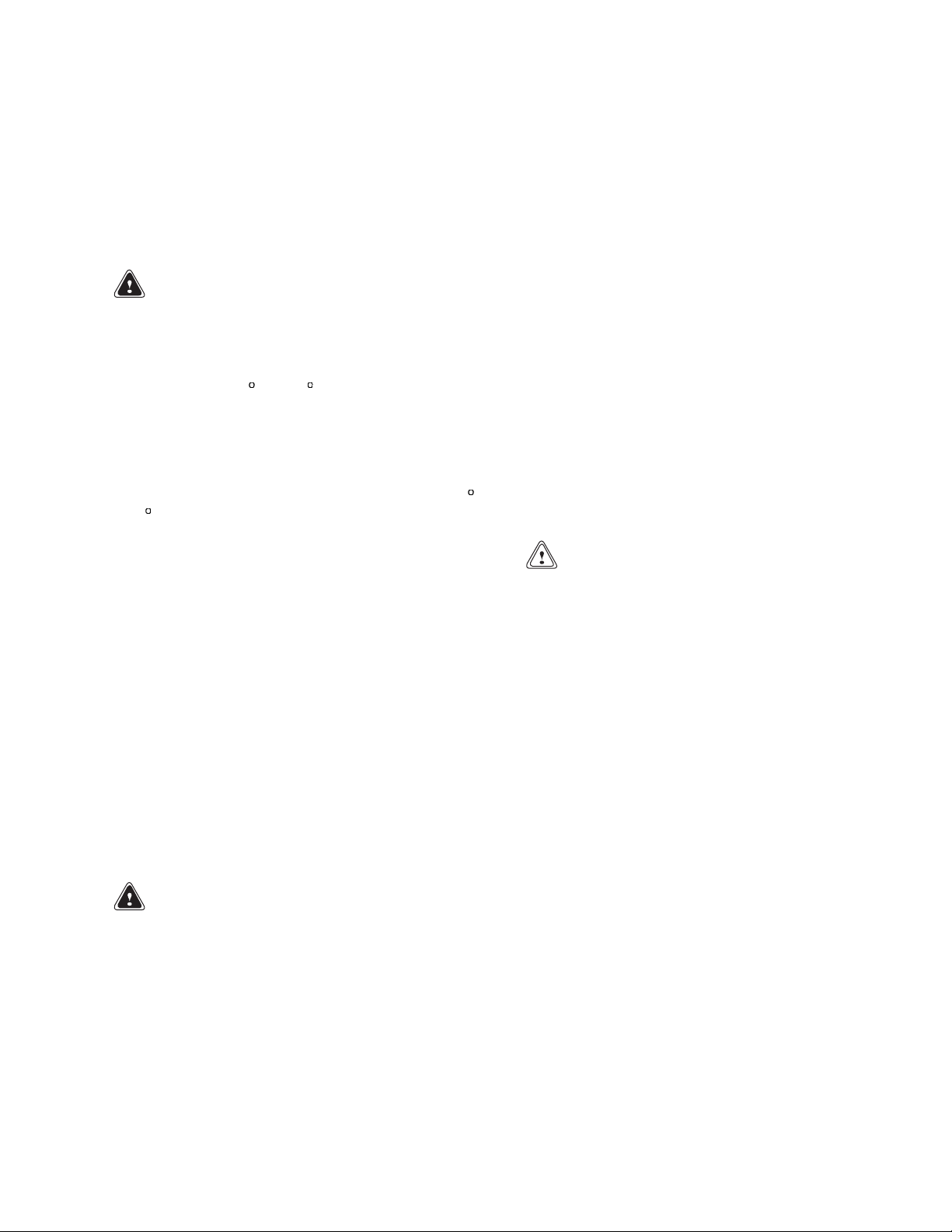
Description
The cylinder head is cast iron and has one inlet valve
and one exhaust valve for each cylinder. The valve
seats and the valve guides are replaceable. The fuel
injectors are in the cylinder head. The overhead
valveassemblyisactuatedbyacamshaftinsideof
the engine block. A gear train, turned by the crankshaft, turns the camshaft, coolant pump, injection
pump, and a power-takeoff (PTO) which is available
for additional equipment. The hydraulic pump for
the steering function or a compressor is normally
turned by the PTO. The fuel pump is actuated by the
camshaft. See Figure 1.
The crankshaft has seven main bearings. The main
bearing in the center of the crankshaft is the thrust
bearing and has thrust washers on both sides of the
bearing.
With M.E.A.S. sealed studs, the sealed end must
be fitted into the cylinder head/cylinder block,
etc. Ensure that the threaded holes have a
1.59 mm (0.0626 in.), 45
M.E.A.S. sealant is not removed. If the fasteners have to be removed and fitted again, the
threads must be cleaned and a suitable sealant
used.
Observe the previous WARNING S and CAUTIONS
before repairing any equipment.
air. Each piston has three piston rings (two compression rings and an oil control ring). The top compression ring has a special insert for the groove, to reduce
wear. Axial location of the fully floating piston pin is
by circlips. The piston pin is off-center to reduce the
noise level. A jet for cooling oil to the bottom of the
piston is installed.
The cooling fan and the alternator are turned by a
drive belt. The cooling fan is not connected to the
coolant pump. The coolant pump is turned by the
gear for the fuel injection pump in the timing gear
case.
The timing, speed adjustment, and quantity of fuel
sent to the fuel injectors is controlled electronically
by the Electronic Control Module (ECM).
chamfer so that the
The cylinder block is cast iron and has cylinder liners
that can be replaced during overhaul.
A Fastram™ combustion chamber in the top of each
piston is designed to give an efficient mix of fuel and
2
A Bosch VP30 seriesfuelinjection pumpisused onall
1100 VK engines. Special tools are needed to repair
an injection pump, and they are normally sent to an
authorized repair station if repairs are necessary.
Page 11
600 SRM 1068 Description
1. FILL CAP FOR ENGINE OIL
2. FUEL FILTER
3. FUEL
4. COOLANT PUMP
5. AIR COMPRESSOR
6. VIBR
7. OIL FILTERS
INJECTION PUMP
ATION DAMPER
8. OIL SUMP
9. ALTERNATOR
10. TURB
11. DIPSTICK, ENGINE OIL
12. FAN DRIVE
13. OIL C
14. TIMING CASE
Figure 1. Engine
OCHARGER
OOLER
3
Page 12
Description 600 SRM 1068
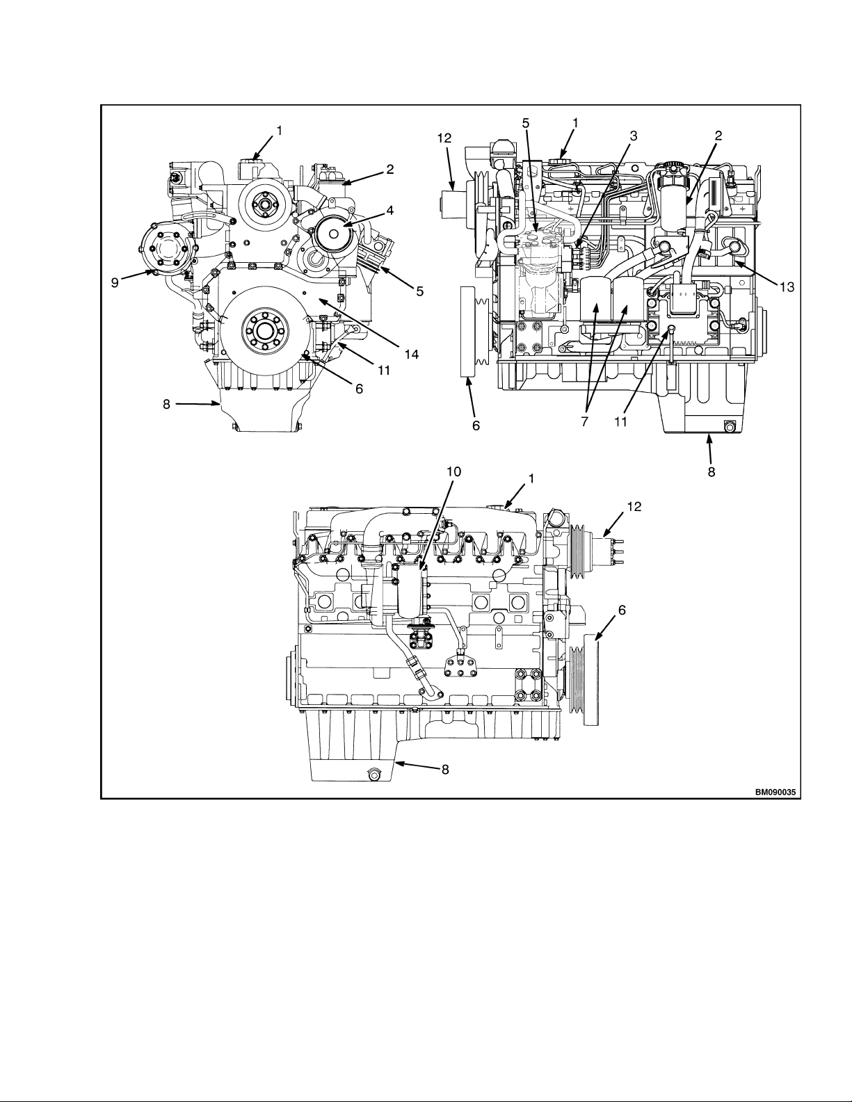
ENGINE SERIAL NUMBER CODES
The engine numberis on a label on the left side of the
engine block. See Figure 2.
1. PART NUMBERS
FOR FUEL
INJECTION PUMP
Figure 2. Serial Number Locations
A typical serial number has the following code:
VK U 090001 H
1234
where:
2. ENGINE SERIAL
NUMBER
3. EMISSIONS LABEL
ENGINE DATA
The specifications and tolerance details for engine repairareinachartattheendofthissection.
1100 (VK)
Power rating at 2300
rpm................................... 129.5 kW (173.7 bhp)
Number of cylinders........ 6
Firing order ..................... 1–5–3–6–2–4
Bore and stroke ...............
Displacemen
Compression ratio ........... 17.25:1
Minimum oil pressure
(at maximum speed
and normal operating
temperature)
Governor speed (no
load) ................................. 280 kPa (41 psi)
See the Periodic Maintenance section for your
model of lift truck.
Idle Speed ........................ 725 to 775 rp
t...................
100 × 127 mm
(3.937 × 5.000 in.)
6.00 liter (3
66 in.
m
3
)
1=Typeofengine:VK=1100
2 = Country of manufacture (U = manufactured in
the United Kingdom)
3 = Serial number
4 = Year of manufacture. The letter indicates the
year of manufacture. The letters I, O, Q, R, and Z
are not used.
If parts or service are required for your engine,
the complete engine number must be given to your
dealer.
Thermostat
Begin to open ..............
Fully open....................
Valve clearance (hot or cold)
Inlet .............................
Exhaust .......................
80 to 84
96
0.20 mm (0.008 in.)
0.45 mm (0.018 in.)
C (176 to 183 F)
C(205F)
4
Page 13

600 SRM 1068 Cylinder Head Assembly Repair
Engine Removal and Installation
See the Frame section for the procedure for removing the engine and transmission. See the Transmis-
sion section for the procedure to separate the transmission from the engine.
There can be a variation in the maximum weight of
the engine depending upon the components that are
attached to it. The following minimum lifting capacity is needed for an engine without coolant, lubricants, or transmission:
1100 (VK) engines 600 kg (1323 lb)
Always use a lifting device that provides avertical lift
above the engine lift brackets as shown in Figure 3.
Never use a single bracket to lift an engine.
Verify the engine brackets are correctly fastened to
the engine. Verify that the valvecover andother components are not damaged by the lifting device. Use a
lifting device to lift and move the heavy components
of the engine: cylinder block, cylinder head, flywheel
housing, flywheel, and crankshaft.
VALVE COVER
1. ENGINE LIFT BRACKETS
Figure 3. Lifting an Engine
Cylinder Head Assembly Repair
Legend for Figure 4
1. VALVE COVER
2. OIL FILLER CAP SEAL
3. OIL SEPARATOR ASSEMBLY SEAL
4. VALVE COVER GASKET
5. CAPSCREW ASSEMBLY
Remove
1. Disconnect the breather pipe.
2. Remove the capscrews and sealing washers from
thevalvecover. SeeFigure4.
3. Lift the valve cover and gasket from the cylinder
head. The valve cover gasket fits between the
valve cover and the induction manifold.
Figure 4. Valve Cover
5
Page 14
Cylinder Head Assembly Repair 600 SRM 1068
Install
1. Check the condition of the valve cover gasket,
bolts, and seal washers. Replace components as
necessary. Verify that the surfaces are clean.
2. Install the valve cover and gasket on the cylinder
head. See Figure 4.
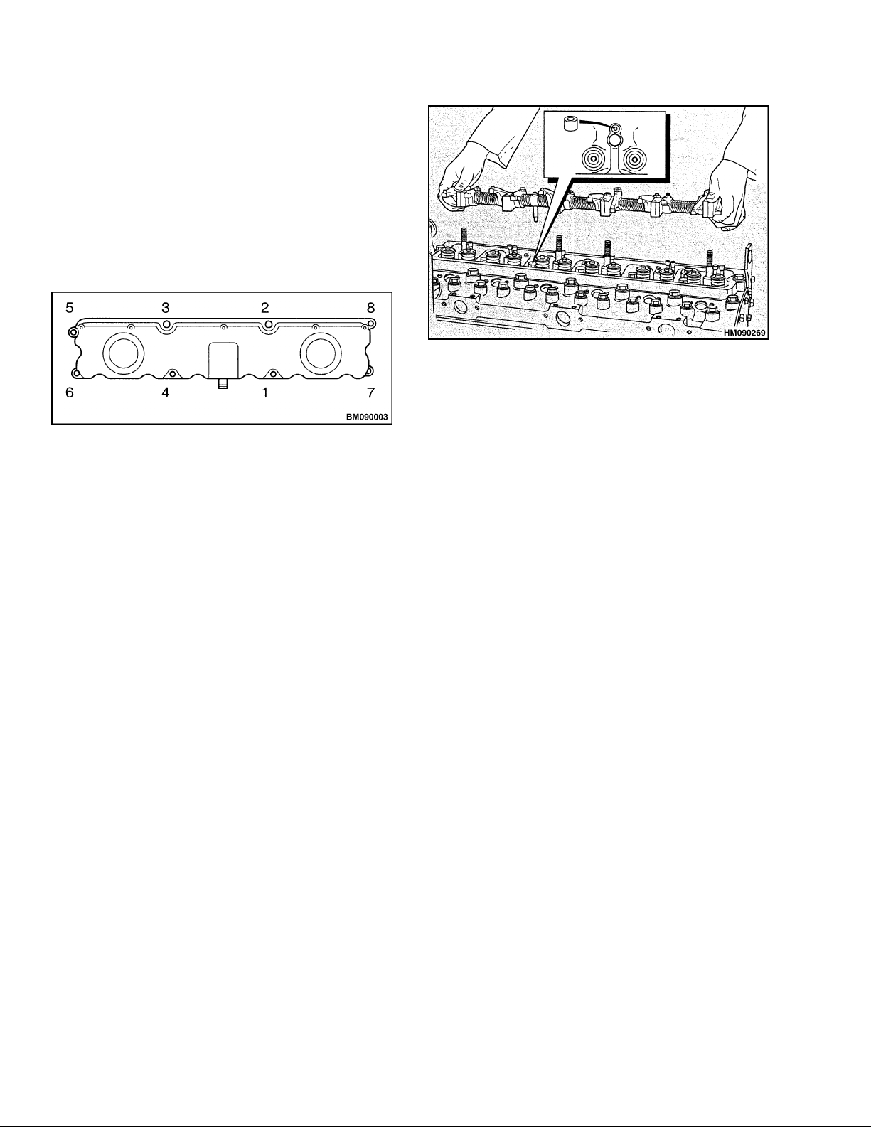
3. Install the valve cover bolts. Torque to 9 N•m
(80 lbf in) in sequence shown in Figure 5.
Figure 6. Rubber Seal Location
Inspect
Clean and inspect all the components for wear and
Figure 5. Valve Cover Torque Sequence
4. Connect the breather pipe.
damage. Check the clearance of the rocker arms on
the rocker arm shaft. If the clearance is greater than
0.09 mm (0.0035 in.), install a new rocker arm, or
install a new rocker arm shaft if it is worn.
ROCKER ARM ASSEMBLY
Assemble
Remove
1. Verify that the lubrication holes in the rocker
1. Remove the valve cover.
2. Loosen the nuts evenly that fasten the brackets
for the rocker arm shafts to the cylinder head.
Loosen the brackets at each end of the cylinder
head first and loosen the brackets in sequence
towards the center. Remove the nuts and washers when the pressure is removed from the rocker
arms. Lift the rocker arm assembly from the
cylinder head.
3. Remove the rubber seal from the oil supply con-
nection or the hole for the oil supply in the cylinder head. See Figure 6.
Disassemble
arms and the rocker arm shaft are open and
clean.
2. Lubricate the components with clean engine oil
as they are assembled on the rocker arm shaft.
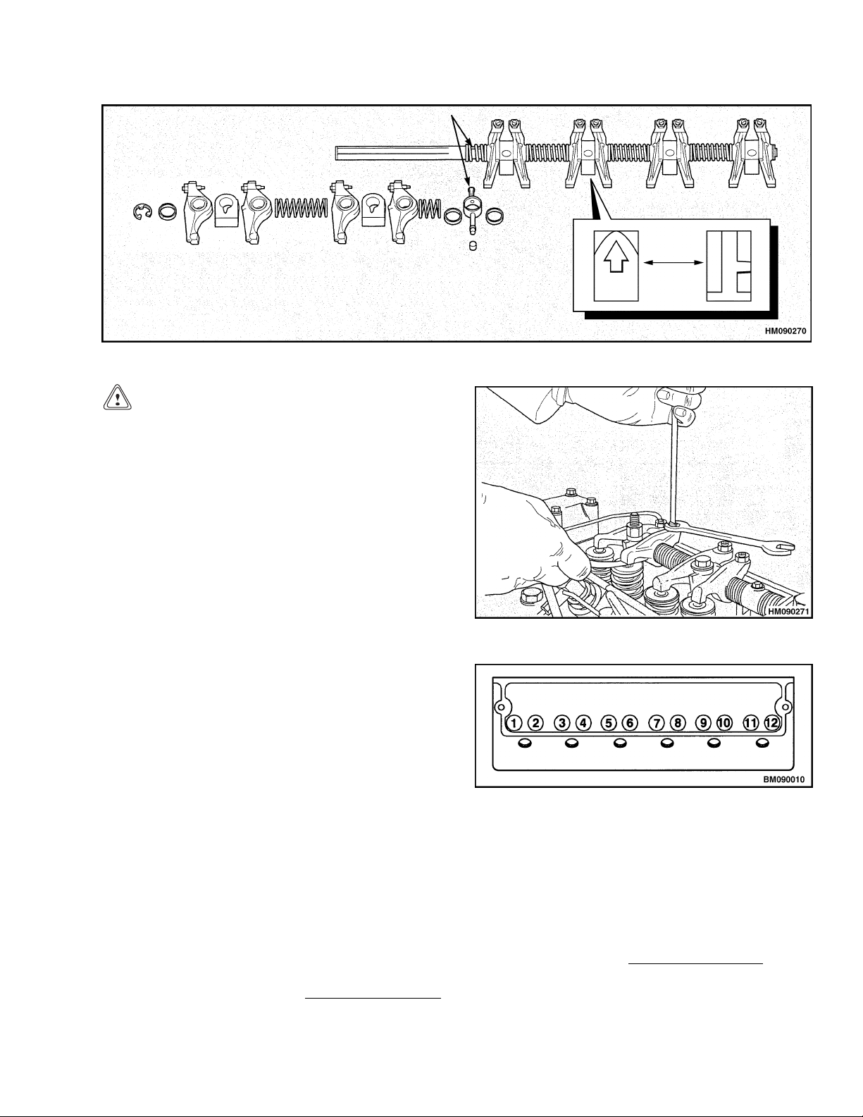
Verify the components are assembled in the correct order. See Figure 7. Verify that the location screw for the oil supply connection is fitted
correctly in the rocker arm shaft and torqued to
4 N•m (35 lbf in). Install the clips at the ends of
the rocker arm shaft.
Install
1. Verify that the rocker arm assembly is clean and
dry.
1. Remove the clips from both ends of the rocker
arm shaft. Verify that the ends of the rocker arm
shaft are not damaged. Loosen the location screw
for the oil supply connection.
2. Make a note of the position of each component on
the rocker arm shaft so that they can be assembled correctly. Remove the components from the
rocker arm shaft.
6
2. Install a new rubber seal in the hole for the oil
supply in the cylinder head. See Figure 6.
3. Check that the push rods fit correctly in the sock-
ets for the tappets. Install the rockerarm assembly over the four studs, insert the oil supply connection into the oil supply hole in the cylinder
head.
Page 15
600 SRM 1068 Cylinder Head Assembly Repair
Figure 7. Rocker Arm Assembly
CAUTION
Loosen any tappet adjustment screws that may
tighten during the following procedure.
4. Verify that the alignment of the rocker arms
and the push rods is correct. Install the nuts
and washers on the studs that hold the brackets
for the rocker arm shafts to the cylinder head.
Tighten the nuts evenly. Begin tightening the
nuts at the center of the rocker arm shaft and
tighten in sequence towards the ends of the
shaft. The final torque on the nuts is 75 N•m
(55 lbf ft).
5. Check and adjust valve tip clearances. See Valve
Clearance Adjustments.
VALVE CLEARANCE ADJUSTMENTS
The valve clearance is measured between the top of
the valve stem and the rocker arm as shown in Figure 8.
Valve clearance (hot or cold)
Inlet
Exhaust
Number one cylinder is at the front of the engine.
The inlet valve is the first valve in the sequence. See
Figure 9.
1. Turn the crankshaft in the normal direction of
rotation until the inlet valve of number six cylinder has just opened and the exhaust valve of the
same cylinder has not fully closed. Check the
clearances of the valves of n
and adjust them as necessary.
0.20 mm (0.008 in.)
0.45 mm (0.018 in.)
umber one cylinder
Figure 8. Valve Clearance Adjustment
e9. ValvePositions
Figur
NOTE:
(21 lb
2. Turn t
The torque for the locking nut is 27 N•m
fft).
he crankshaft in the normal direction of ro-
n until the inlet valve of number two cylin-
tatio
as just opened and the exhaust valve of the
der h
cylinder has not fully closed. Check the
same
e clearances on n
valv
them as necessary.
just
umber five cylinder and ad-
7
Page 16
Cylinder Head Assembly Repair 600 SRM 1068
3. Turnthecrankshaftinthenormaldirectionofro-
tation until the inlet valve of number four cylinder has just opened and the exhaust valve of the
same cylinder has not fully closed. Check the
valve clearances on n
adjust them as necessary.
4. Turnthecrankshaftinthenormaldirectionofro-
tation until the inlet valve of number one cylinder has just opened and the exhaust valve of the
same cylinder has not fully closed. Check the
valve clearances on n
just them as necessary.
umber three cylinder and
umber six cylinder and ad-
5. Turnthecrankshaftinthenormaldirectionofro-
tation until the inlet valve of number five cylinder has just opened and the exhaust valve of the
same cylinder has not fully closed. Check the
valve clearances on n
just them as necessary.
6. Turnthecrankshaftinthenormaldirectionofro-
tation until the inlet valve of number three cylinder has just opened and the exhaust valve of the
same cylinder has not fully closed. Check the
valve clearances on n
just them as necessary.
NOTE: After valve adjustments, lubricate the rocker
assembly with clean engine oil.
umber two cylinder and ad-
umber four cylinder and ad-
VALVE SPRINGS
NOTE: This procedure is normally for changing the
valve springs of a single cylinder while the cylinder
head is still installed on the engine. If the valves and
springs must be removed from the cylinder head for
repairs, see the procedures under Valves and Valve
Springs, later in this section.
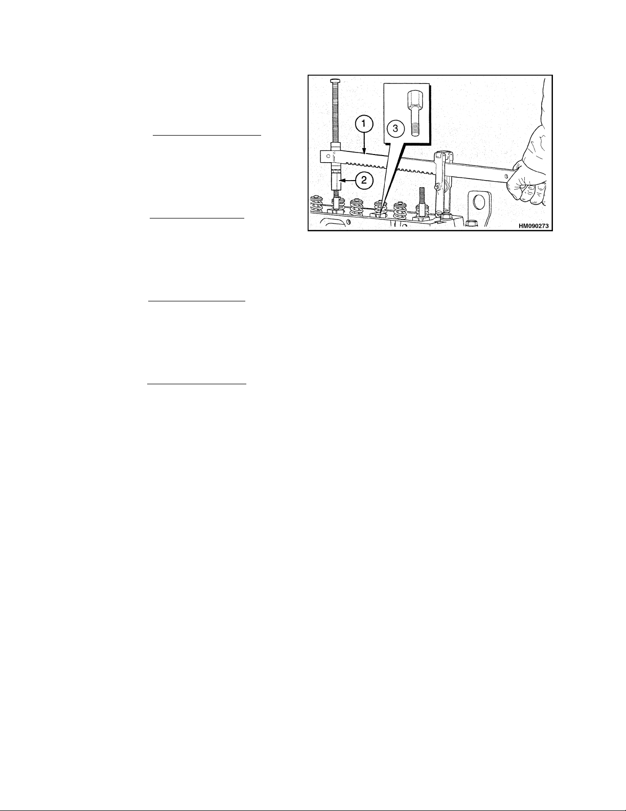
Special Tools: Valve spring compressor
Stud adapter
Setscrew adapter
1. VALVE SPRING
COMPRESSOR
2. STUD ADAPTER
Figure 10. Valve Spring Compressor
5. Compress the valve springs and remove the retainers. Verify the valve springs are compressed
parallel tothe valve stems, or the valve stems can
be damaged.
NOTE: Do not turn the crankshaft while the valve
springs are removed.
6. Release the valve spring compressor and remove
the retainer cap and valve springs.
NOTE: The outerdiameter of the exhaustvalve guide
is 1 mm (0.039 in.) larger than the inlet valve guide.
To prevent leakage past the inlet valve stem it is important that thelarger exhaust valve seal isnot fitted
into the inlet guide. The seals are color coded.
7. Install new valve stem seals on the valve guides.
Verify that the brown seal is installed on the
exhaust valve and the green seal on the inlet
valves.
8. Install the new valve springs. The springs can be
fitted with either end toward the cylinder head.
3. SETSCREW
ADAPTER
1. Remove the valve cover.
2. Turn the crankshaft in the normal direction of
rotation until the piston for the cylinder is at top
dead center (TDC). The inlet valve will just open
and the exhaust valve will not be fully closed
when the cylinder is at TDC.
3. Remove the rocker arm assembly.
4. Install the spring compressor and the adapter.
SeeFigure10.
8
9. Install the retainer cap.
10. Use the valve spring compressor to compress the
valve springs and install the retainers. Remove
the valve spring compressor.
11. Install the rocker arm assembly.
12. Check the valve clearances. See Valve Clearance
Adjustments.
13. Install the valve cover.
Page 17
600 SRM 1068 Cylinder Head Assembly Repair
NOTE: Valvespringscanbechangedintwocylinders
at a time.
When the piston in cylinder one is at TDC, the piston
in cylinder six is also at TDC. When the piston in
cylinder two is at TDC, the piston in cylinder five is
also at TDC. When the piston in cylinder three is at
TDC,thepistonincylinderfourisalsoatTDC.
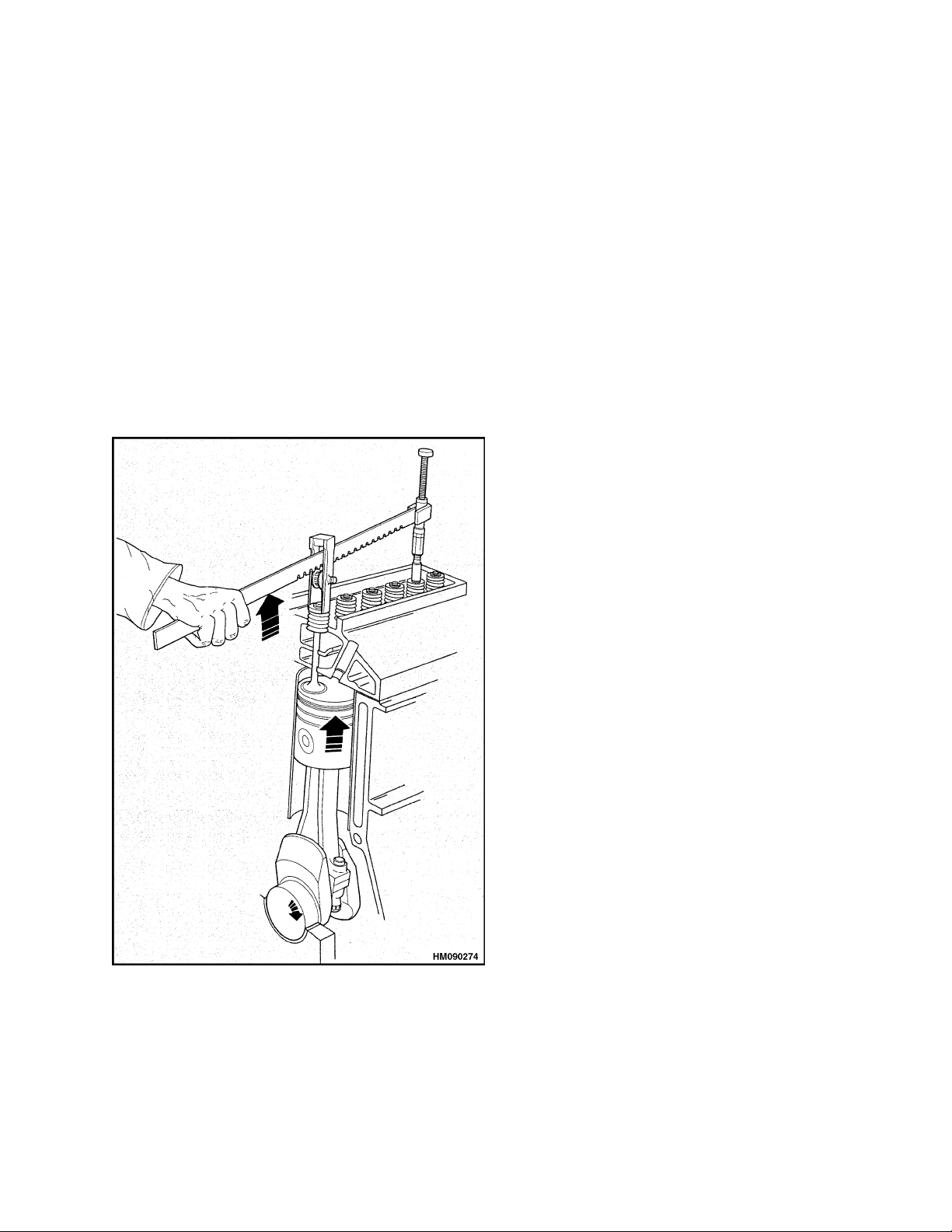
If the rocker arm assembly was removed before TDC
was found, install the valve spring compressor and
compress the valve springs to open the valve. Turn
the crankshaft by hand in the normal direction until
the piston touches the valve. Continue to turn the
crankshaft and, at the same time, release the pressure on the valve spring compressor until the piston
isatTDC.SeeFigure11.
CYLINDER HEAD ASSEMBLY
Remove
1. If the engine is still in the lift truck, do the fol-
lowing procedures:
a. Disconnect the battery terminals.
b. Drain the cooling system.
c. Disconnect the sender unit for the coolant
temperature gauge.
2. If equipped, remove closed circuit breather unit.
3. Remove the Machine Interface Connector (MIC)
connection from the mounting bracket if the
mounting bracket is attached to the cylinder
head.
4. Remove the air intake hose.
5. Removethefuellinebetweenthecoldstartaid
in the induction manifold and the fuel filter. Disconnect the electrical connection and electrical
connectors from sensors.
Figure 11. Find TDC With Valve Spring
Compressor
6. Disconnect all connections to the turbocharger
and remove turbocharger. See Turbocharger, Remove.
7. Remove the induction manifold capscrews.
8. Remove the induction manifold and gasket from
the cylinder head. Discard the gasket.
9. Remove exhaust manifold fasteners and the ex-
haust manifold.
10. Remove the low pressure fuel lines between the
fuel injection pump and the fuel filter. Remove
the fuel filter bracket and the fuel filters.
11. Removethehighpressurefuellines. Useasep-
arate wrench to prevent movement of the outlets
of the fuel injection pump when the fuel lines are
disconnected. Put plugs in the open ports of the
fuel injection pump.
12. Remove the fuel injectors from the cylinder head.
Keep the fuel injectorsclean andprevent damage
to the nozzles.
13. If an air compressor is installed, remove the
coolant pipe between the cylinder head and the
compressor. Remove the coolant pipe between
the bypass connection and the compressor.
9
Page 18
Cylinder Head Assembly Repair 600 SRM 1068
14. Loosen the hose clamp and remove the coolant
bypass hose from the cylinder head. Remove the
capscrews andremove thecoolant bypass connection and the hose.
15. Disconnect the coolant temperature sender.
16. Remove the valve cover. See Valve Cover, Re-
move.
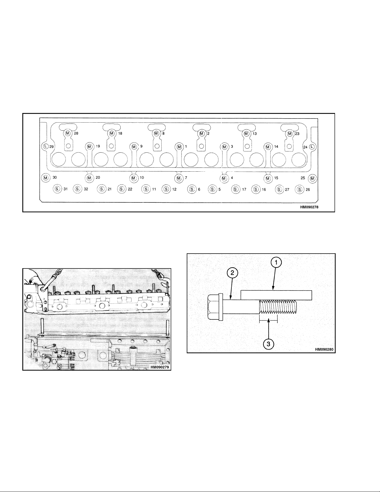
Figure 12. Cylinder Head Tightening Sequence
17. Remove the rocker arm assembly. See Rocker
Arm Assembly, Remove.
18. Remove the push rods.
19. Loosen the capscrews for the cylinder head
evenly in a reverse sequence from the sequence
showninFigure12.
20. Lift the cylinder head from the engine block. Do
not use a pry bar between the cylinder head and
theengineblock,thatcancausedamagetothe
gasket surfaces. See Figure 13.
Figure 13. Cylinder Head Removal
21. Inspect the capscrews for the cylinder head with
a straightedge. See Figure 14. Check that the
capscrews are straight and do not have distortion. If there is a reduction in the diameter of the
thread that has not been in engagement with the
cylinder block, the capscrew must be discarded.
1. STRAIGHTEDGE
2. CAPSCREW MUST BE STRAIGHT AND
WITHOUT DISTORTION
3. THREADS MUST BE IN GOOD CONDITION AND
NOT HAVE A REDUCED DIAMETER
Figure 14. Capscrews Inspection
10
Page 19
600 SRM 1068 Cylinder Head Assembly Repair
Install
Special Tools: Angle gauge to tighten the
capscrews for the cylinder head
1. Ver
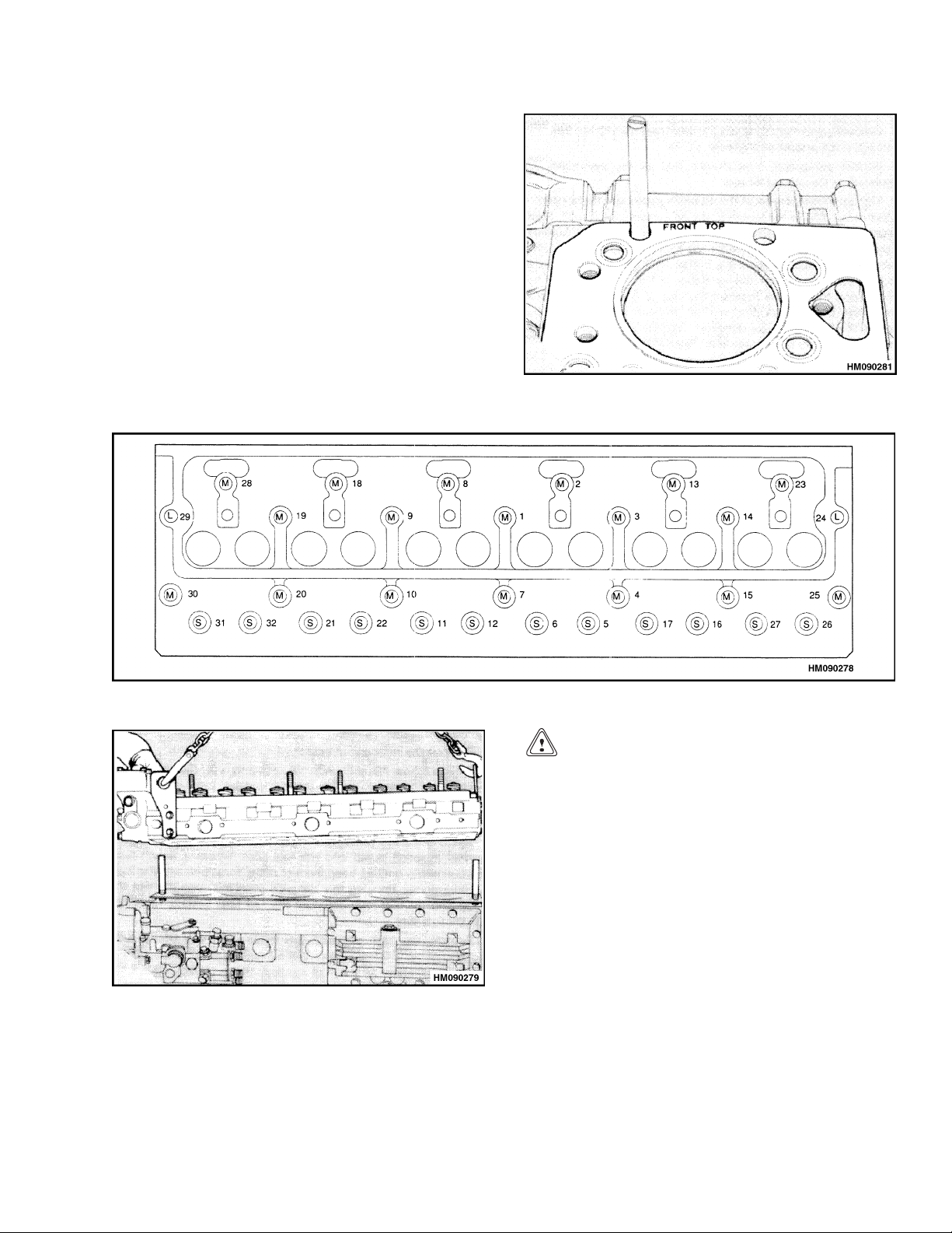
2. Ins
3. Us
ify the surfaces of the cylinder head and the
oftheengineblockareclean. Verifythat
top
re is no dirt or objects in the cylinders.
the
tall the gasket for the cylinder head as shown
igure15. VerifytheTOPFRONTisinthe
in F
rect position. Do not use any gasket sealant
cor
any of the surfaces.
on
e two 1/2 UNF studs in positions 25 and 30.
e Figure 16. Lower the cylinder head into po-
Se
tion on the engine block. See Figure 17.
si
Figure 15. Head Gasket Position
Figure 16. Cylinder Head Tightening Sequence
Figure 17. Cylinder Head Installation
CAUTION
Therearethreelengthsofcapscrews.S=short,
M = medium, L = long. Figure 16 shows their positions in the engine. Verify that the capscrews
are installed in the correct positions.
4. Lubricate the capscrews with a thin coat of oil
and install them into their holes in the cylinder
head. When the cylinder head and gasket are
held in position, remove the two studs and install
the two capscrews in those positions.
5. Evenly tighten the capscrews in the sequence
shown in Figure 16. The final torque on the capscrewsis110N•m(81lbfft).
11
Page 20
Cylinder Head Assembly Repair 600 SRM 1068
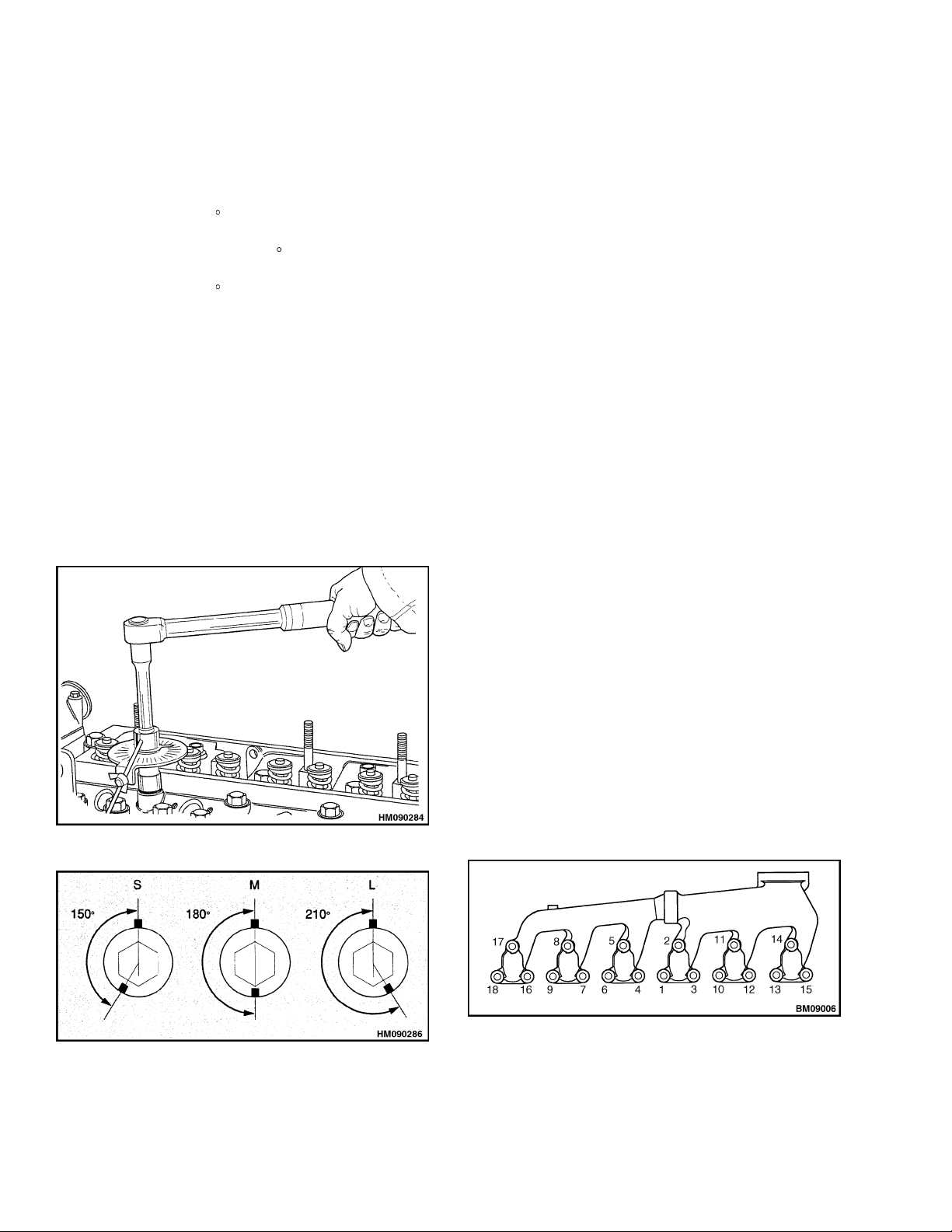
6. Verify all of the capscrews are tightened to the
correct torque described inStep5. The capscrews
must be further tightened in the sequence shown
in Figure 16 accordingtothefollowing procedure:
a. The short capscrews (S) mustbetightened an
additional 150
b. The medium capscrews (M) must be tight-
ened an additional 180
c. Thelongcapscrews(L)mustbetightenedan
additional 210
NOTE: A special tool shown in Figure 18 can be used
for this procedure to measure the tightening angles.
If an angle gauge is not available, make a mark in
alinewithoneofthecornersofthecapscrew. See
Figure 19. Make another mark at the correct angle
(counterclockwise) on the edge of the flange of the
cylinder head for each capscrew and according to the
length of each capscrew. Tighten each capscrew in
the correct sequence until the two marks are aligned.
7. Install the push rods in the engine. Verify that
the end of each push rod fits correctly in the tappet socket.
(2.5 flats).
(3.0 flats).
(3.5 flats).
8. Install the rocker arm assembly per Rocker Arm
Assembly, Installl.
9. Adjust the valve clearances per Valve Clearance
Adjustments.
10. Install the fuel injectors per Fuel Injectors, Install.
11. Install the high pressure fuel lines between the
fuel injection pump and the fuel injectors. Use
a separate wrench to prevent movement of the
outlets of the fuel injection pump when the fuel
lines are connected. Tighten the connection nuts
to 27.5 N•m (20 lbf ft).
12. Install the fuel filter and bracket. Install the lowpressure fuel lines between the fuel filter and the
fuel injection pump.
13. If equipped, reinstall the MIC to the MIC mounting bracket.
14. Install the coolant bypass connection. Tighten
the capscrews and the hose clamp.
Figure 18. Angle Gauge
15. If an aircompressor is installed on the engine, install the coolant pipe between the cylinder head
and the compressor. Install the pipe between the
coolant bypass and the compressor.
NOTE: Do not use sealant compound on gaskets of
the manifold.
16. Verify the exhaust manifold gaskets and gasket
surfaces are clean and not damaged.
17. Place the temporary studs in the cylinder head.
a. For two-piece exhaust manifolds, place tem-
porary studs in positions 4, 8, 11, and 15 of
the cylinder head. See Figure 20.
Figure 19. Tighten Cylinder Head Capscrews
12
Figure 20. Two-Piece Exhaust Manifold
Tightening Sequence
Page 21
600 SRM 1068 Cylinder Head Assembly Repair
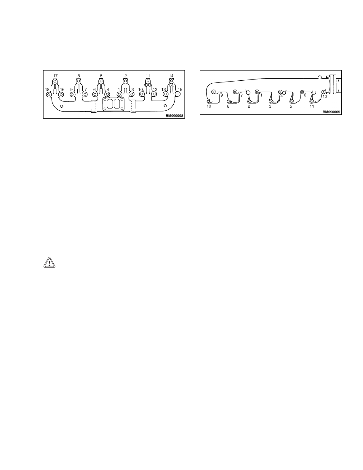
b. For three-piece exhaust manifolds, place
temporary studs in positions 2, 5, 14, and 17
of the cylinder head. See Figure 21.
Figure 21. Three-Piece Exhaust Manifold
Tightening Sequence
18. Place the exhaust manifold gaskets in position
over the studs. Verify the gaskets are in the correct position.
19. Reassemble the sections of the exhaust manifold
and place in position over the temporary studs.
20. Insert the capscrews into all positions that do not
have temporary studs and torque to 12.5 N•m
(9 lbf ft).
21. Remove temporary studs and insert remaining
capscrews and torque to 12.5 N•m (9 lbf ft).
22. Torque the capscrews again in sequence to
12.5 N•m (9 lbf ft). See Figure 20 and Figure 21.
CAUTION
Before the inlet manifold capscrews are installed again, any loose M.E.A.S in the cylinder
head holes must be removed to allow the manifold to be fully tightened.
25. Install the induction manifold capscrews and
torque in sequence to 22 N•m (16 lbf ft). See
Figure 22.
Figure 22. Induction Manifold Tightening
Sequence
26. Install the fuel line between the fuel filter and
the cold start aid. If the engine is inthe lift truck,
install the electrical connection to the cold start
aid.
27. Install the air intake hose.
28. Install the turbocharger. See Turbocharger, In-
stall.
29. Install the closed circuit breather assembly if
previously removed.
30. Install the fuel lines between the fuel filter and
the fuel injection pump.
31. If the engine is still in the lift truck, do the fol-
lowing procedures:
a. Connect the sender unit for the coolant tem-
perature gauge.
b. Connect the hoses forthecoolant system. Fill
the cooling system.
Do not scratch or damage the flange faces of
the inlet manifold.
NOTE: Thecapscrewsthatretainthemanifoldtothe
cylinder headhave M.E.A.S applied to the threads. If
the capscrews are removed and installed again, the
threads must be cleaned and POWERPART threadlock sealant used.
23. Place a new induction manifold gasket into posi-
tion on the cylinder head.
24. Place the induction manifold in position on the
cylinder head.
c. Connect the battery terminals.
d. If the engine is ready to operate, remove the
air from the fuel system. See the procedure
described in Fuel System Air Removal.
32. Whentheenginecanbestarted,runitatlow
speed. Check that oil flows from the holes in the
rocker arms. If the oil flow is correct, install the
valve cover. See Valve Cover, Install.
NOTE: It is not necessary to tighten the cylinder
head capscrews again with the engine hot or after a
limited period of service.
13
Page 22
Cylinder Head Assembly Repair 600 SRM 1068
VALVES AND VALVE SPRINGS
Special Tools: Valve spring compressor
Stud adapter
Setscrew adapter
ove
Rem
1. Rem
2. Cle
3. Check the depth of the valves below the face of
ove the cylinder head. See Cylinder Head
embly, Remove.
Ass
an the bottom face of the cylinder head and
ck the depth of the heads of the valves below
che
e face of the cylinder head. See Figure 23.
th
Figure 23. Valves Depth Check
thecylinderheadbeforethevalvespringsareremoved. Put thedial indicator and fixture orother
measuring tool on the face of the cylinder head
and set the gauge to zero. Carefully put the dial
indicator over the head of each valve and make a
note of the measurement. The maximum service
depth is shown in the Engine Specifications. If a
valve is below the depth limit, remove the valve
and install a new valve in that position. If the
valve depth is still below the limit, the valve seat
must be replaced. See New Valve Seats, Install.
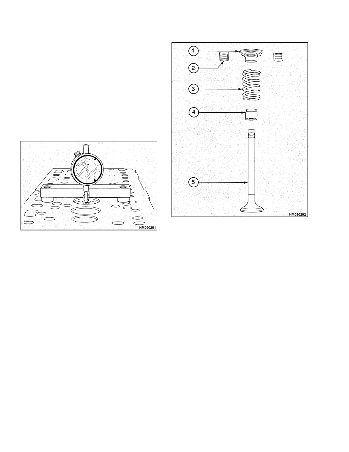
1. CAP
2. COLLET (2)
3. SPRING
Figure 24. Valve Components
6. Release the valve stem compressor. Remove the
valve spring cap, valve springs, and seal.
7. Repeat Step 5 and Step 6 to remove the other
valves.
4. VALVE STEM SEAL
5. VALVE
Inspect
1. Check the valves for cracks. Check the stems of
the valves for wear and the correct clearance in
their valve guides. See Valve Guides.
4. If the valves will be used again, make a mark
on each valve head so that they can be installed
again in the same positions.
5. Usethevalvespringcompressorandthecorrect
adapter to compress the valve springs and remove the retainers. Verify the valve springs are
compressed parallel to the valve stems, or the
valve stems can be damaged. See Figure 24.
14
2. Check that the seat faces of the valves are not
badly burned. Seat faces of valves that are damaged, but can be repaired, must be checked for
valve depth when they are installed. See Figure 23. When new valves are installed, the valve
depth must be checked.
3. Check that the load on the valve springs is correct at their installed length. See Engine Specifications.
Page 23
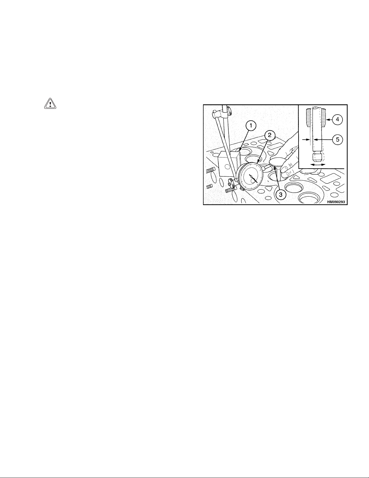
600 SRM 1068 Cylinder Head Assembly Repair
4. Install new valve springs during a complete over-
haul of the engine.
Install
1. Lubricate the valve stems with engine oil when
they are installed in their valve guides.
CAUTION
The outer diameter of the exhaust valve guide
is 1 mm (0.039 in.) larger than the inlet valve
guide. To prevent leakage past the inlet valve
stem it is important that the larger valve seal
is not installed into the inlet guide. The seals
are color coded.
2. Install new seals on the valve guides. Verify that
the brown seal is installed on the exhaust valves
and the green seal is installed on the inlet valves.
3. Install the inner and outer valve springs on the
seat washer. The springs can be installed with
either end to the cylinder head.
4. Use the valve spring compressor and the correct
adapter to compress the valve springs. Install
the retainers. Verify the valve springs are compressed parallel to the valve stems or the valve
stems can be damaged.
5. Repeat the installation procedure for each valve.
VALVE GUIDES
Inspect
1. Check the valve guides for wear. The maximum
clearance between the valve stem and the bore of
the guide is 0.100 mm (0.004 in.) for inlet valves
and 0.121 mm (0.005 in.) for exhaust valves. If
the clearance is greater than the limit when a
new valve is installed, the valve guide must be
replaced.
2. The following procedure is for checking the valve
guides (see Figure 25):
valve head away from the plunger of the dial
indicator and set the dial indicator to zero.
d. Move the valve toward the dial indicator
and make a note of the movement. If the
reading is equal to or greater than the maximum clearance, a new valve guide must be
installed.
1. MAGNETIC BASE
2. DIAL INDICATOR
3. VALVE HEAD
Figure 25. Valve Guides Check
NOTE: The partially finished valve guides are
reamed and the valve seats are cut in one operation
with a special tool. This is done to ensure the concentricity of the valve seat to the valve guide and
provide a good seal between the guide and its seat.
New valves and valve seat inserts must be installed
each time a new valve guide is used.
4. VALVE GUIDE
5. MAXIMUM
CLEARANCE
Remove
Install the tool for removal and replacement and the
adapter on the valve guide. Pull the valve guide from
thecylinderhead. SeeFigure26.
Install
1. Verify the bore in the cylinder head is clean.
a. Put a new valve into the valve guide.
b. Install a dial indicator on the cylinder head.
c. Lift the head of the valve approximately
15 mm (0.6 in.) above its seat. Move the
2. Lubricate the outer surface of the new valve
guide with engine oil.
15
Page 24
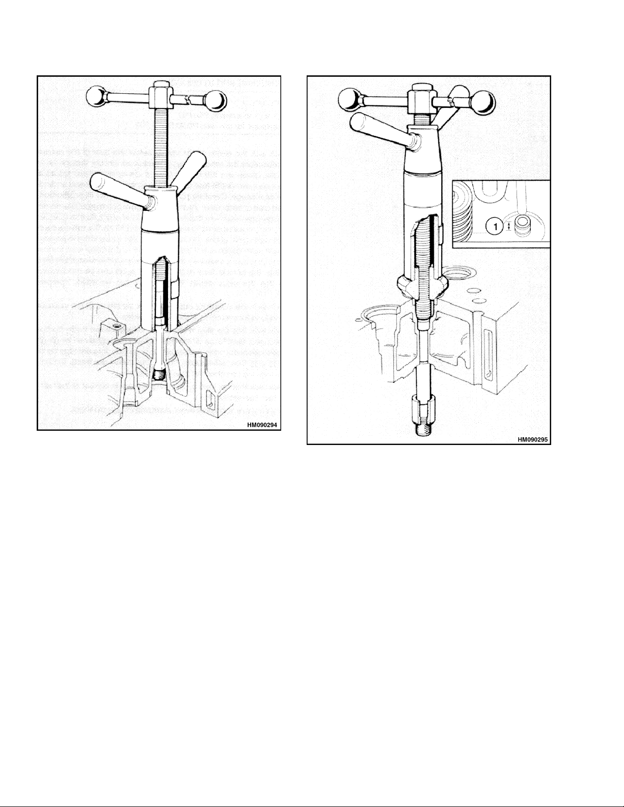
Cylinder Head Assembly Repair 600 SRM 1068
Figure 26. Valve Guide Removal
3. Install the valve guide on the special tool. See
Figure 27. Use the special tool to pull the valve
guide into the cylinder head. When the valve
guide is correctly installed, the valve guide will
extend 14.85 to 15.15 mm (0.585 to 0.596 in.)
above the seat of the valve spring.
CYLINDER HEAD AND VALVE SEATS
Inspect
The cylinder head must be removed and the valves
must be removed from the cylinder head before the
valve seats can be inspected and repaired. Carefully
clean the cylinder head.
1. Check the cylinder head for cracks. Carefully
check the areas around the valve seats and
around the holes for the fuel injectors.
1. 14.85 t
SEAT OF VALVE SPRING
2. Use a straightedge and spacer gauges to check
the cylinder head for distortion across and along
its face that joins the engine block. See Engine
Specifications. If the distortion is more than the
specifications, the face can bemachined. Remove
only the minimum metal so that the thickness of
the cylinder head will not be less than 102.79 mm
(4.047 in.) after the cylinder head has been machined.
NOTE: After the cylinder head has been machined,
the valve seats must bechecked for the correct depth.
See Valves and Valve Springs, Inspect. If the depth of
the valve seats must be increased, use the minimum
limit to allow for later wear.
3. Check the valve seats for wear and damage. Before any work is done on the valve seats, verify
o 15.15 mm (0.585 to 0.596 in.) ABOVE
Figure 27. Valve Guide Installation
16
Page 25
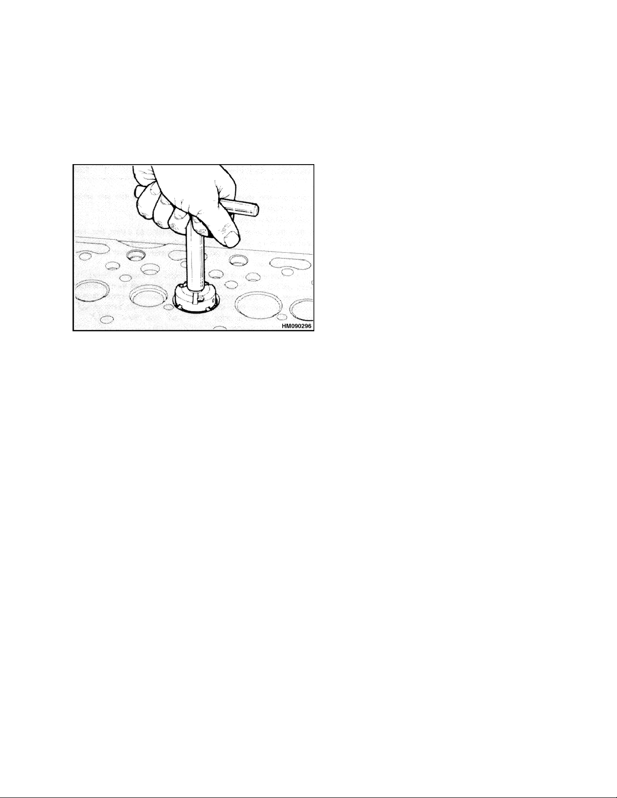
600 SRM 1068 Piston and Connecting Rod Assemblies Repair
the valve guides are good. See Valve Guides, Inspect for inspection and replacement.
4. Damaged valve seats can be repaired with a cut-
tertool. SeeFigure28. Ifthevalveseatcannot
be repaired so that the valve depth is within the
specifications, the valve seat must be replaced.
Figure 28. Valve Seats Cutter
Repair
Special Tools: Cutter for inlet valve seats
Cutter for exhaust valve seats
Val ve gu id es re am er
1. Install the correct cutter into the valve seat that
is to be repaired. Carefully turn the cutter in a
clockwise direction. Remove only the minimum
metal to repair the valve seat. Keep the valve
seat as narrow as possible.
3. Check the valve depth. See Valves and Valve
Springs, Inspect. If the valve seat is badly damaged or worn, replace the valve seat as described
in the following paragraphs.
New Valve Seats, Install
1. Remove the valve guide. Clean the bore and in-
stall a new valve guide. See Valve Guides for inspection and replacement.
2. Usetheboreofthenewvalveguideasapilotand
use a milling machine to remove the old valve
seat. SeetheEngineSpecifications. Cleanthe
particles from the port and the area where the
new valve seat will be installed.
3. If the bottom face of the cylinder head has been
machined, the back face of the new valve seat
must be machined so that itwill not extendabove
the surface of the cylinder head. If the back face
of the valve seat is machined, verify that the dimensions of the outer edge of the back face are
within the Engine Specifications.
4. Usetheboreofthevalveguideasapilot. Use
a press to install the valve seat into the cylinder
head. Verify the valve seat is fully inserted into
the cylinder head.
5. Use a cutter to cut the valve seat at the correct
angle. Check the valve depth as shown in Figure 23. Verify that the dimensions are within the
Engine Specifications.
2. When the valve seat has been cut, remove the
cutter and pilot. Clean the port area and remove
any particles.
Piston and Connecting Rod Assemblies Repair
The connecting rods are forgedfrom steel. The piston
height is controlled by the length of the connecting
rod. Each piston and connecting rod is matched to a
cylinder during assembly to verify the piston height
is correct for combustion efficiency to meet emission
standards.
The manufacturer uses six length grades of connecting rods during assembly to give the correct piston
height. These six length grades are made by machining the small-end bushing a small amount off-center.
Connecting rods for service replacement are available in two length grades.
The combustion chamber is machined into the top
of the piston. See Figure 29. The pistons have two
compression rings and an oil control ring. The groove
for the top compression ring has a hard metal insert
to reduce wear in the groove. The piston skirt has a
layerofgraphitetoreducewear.
17
Page 26
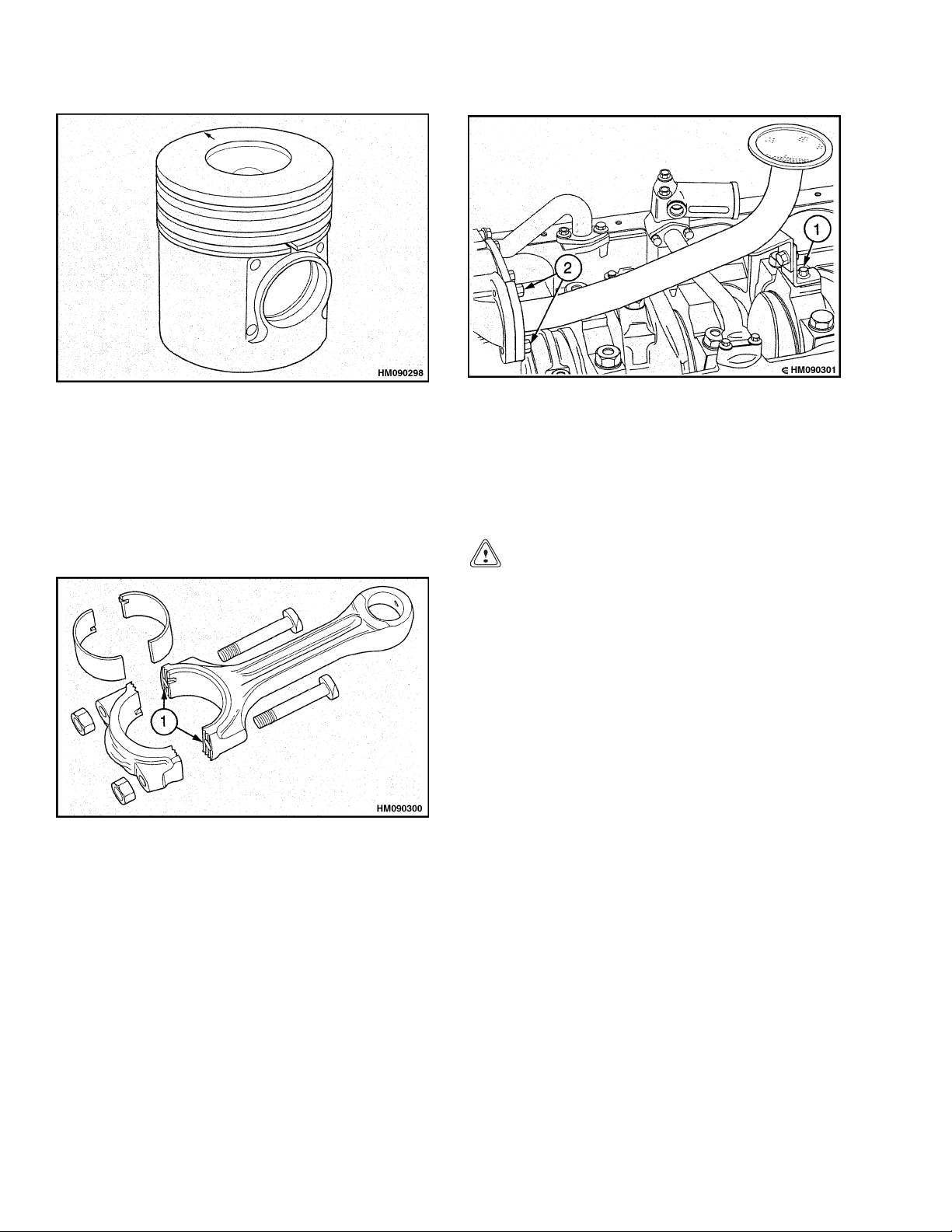
Piston and Connecting Rod Assemblies Repair 600 SRM 1068
Figure 29. Piston
ROD BEARINGS
The engine has grooves (serrations) that are machined in the joint faces of the connecting rod and
bearing cap to keep alignment between the two
parts. The bearing cap is fastened to the connecting
rod with two nuts and special bolts. See Figure 30.
1. SERRATIONS
Figure 30. Connecting Rod Assembly With
Serrations
Remove
1. Drain the engine oil from the sump. Remove the
oil sump. See Oil Sump, Remove.
2. Remove the suction pipe and oil strainer. See
Figure 31. Remove the capscrew that holds the
bracket to the main bearing cap. Remove the two
capscrews from the flange of the suction pipe and
remove the suction pipe and screen. Clean the
faces of both flanges.
1. SUPPORT BRACKET, MAIN BEARING CAP
2. CAPSCREWS, FLANGE, SUCTION PIPE
Figure 31. Sump Screen Removal
3. Turn the crankshaft until the connecting rod to
be removed is at thelowestpositiononthe crankshaft.
CAUTION
Do not permit the connecting rods to hit the
cooling jets for the pistons. If a cooling jet is
hit, the alignment must be checked and the
cooling jet replaced if necessary.
4. Remove the nuts and remove the bearing cap.
5. Remove the lower bearing half from the bearing
cap. Keep the bearing half with its cap.
6. Carefully push the connecting rod up the cylinder bore just enough to permit access to the upper bearing half. Remove the upper bearing half
from the connecting rod. Keep the bearing halves
together.
Install
1. Clean the bearing surfaces of the connecting rod
and the crankshaft. Clean the bearing halves
and lubricate them with clean engine oil.
2. Install the upper bearing half into the connecting rod. Verify that the location tab is installed
correctly into its position in the connecting rod.
See Figure 32.
18
Page 27
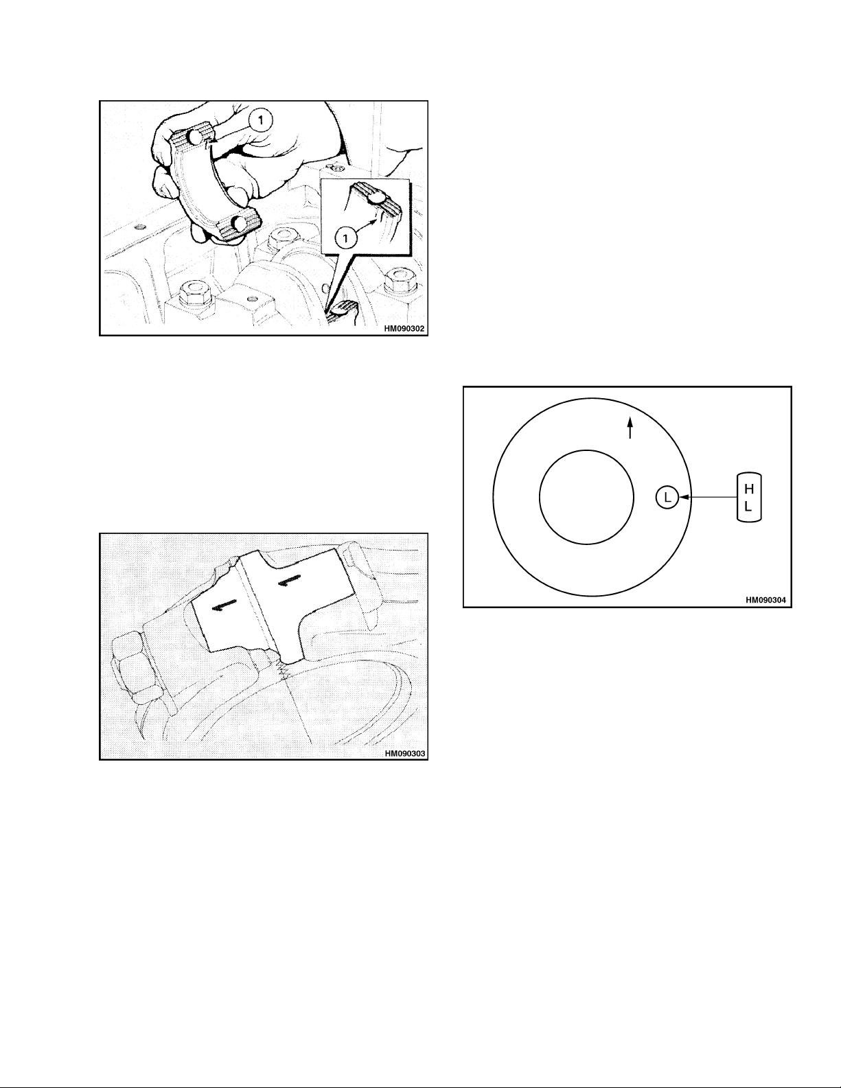
600 SRM 1068 Piston and Connecting Rod Assemblies Repair
pump. Verify that the suction pipe is aligned correctly and then tighten the capscrew that holds
the bracket to the main bearing cap.
6. Install the oil sump. See Oil Sump, Install.
PISTON AND CONNECTING ROD ASSEMBLY
Service Note
If a piston must be replaced, verify that the piston
has the same length grade. An H or an L is stamped
into the top of the piston. See Figure 34. A production piston does not have an H or an L mark. The
1. POSITION OF LOCATION TAB IN BEARING
HALF AND CONNECTING ROD
Figure 32. Rod Bearings Position
3. Install the bearing cap on the connecting rod.
Verify that the assembly number on the bearing cap is the same as the assembly number on
the connecting rod. Verify that the two assembly
numbers are on the same side of the connecting
rod as shown in Figure 33.
piston height must be checked after installation. See
the procedure described in Install.
Figure 33. Bearing Cap Position, Connecting
Rod
NOTE:Newnuts mustbe installed with thebolts that
secure the cap.
4. Install and tighten the nuts evenly to a torque of
125 N•m (92 lbf ft). Verify that the crankshaft
turns freely.
5. Loosely assemble the bracket of the suction pipe
to the main bearing cap. Install a new gasket
and fastenthe flanges ofthe suction linetothe oil
Figure 34. Piston Grade Mark
Remove
1. If the engine is still in the lift truck, drain the
engine oil and the coolant.
2. Remove the cylinder head assembly as described
in Cylinder Head Assembly, Remove. Remove
the carbon from the tops of the bores of the cylinder liners.
3. Remove the oil sump. See Oil Sump, Remove.
4. Remove the suction line and oil strainer. See
Figure 31. Remove the capscrew that holds the
bracket to the main bearing cap. Remove the two
capscrews from the flange of the suction line and
remove the suction line and screen. Clean the
faces of both flanges.
5. Remove the bearing cap and rod bearings as de-
scribed under Rod Bearings, Remove. Mark the
19
Page 28
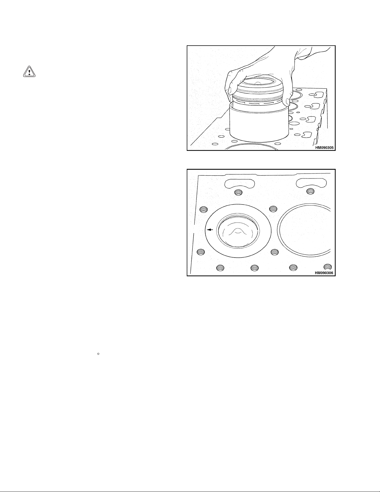
Piston and Connecting Rod Assemblies Repair 600 SRM 1068
bearing caps and rod bearings so that they can
be installed again in their original positions.
CAUTION
Do not permit the connecting rods to hit the
cooling jets for the pistons. If a cooling jet is
hit, the alignment must be checked and the
cooling jet replaced if necessary.
6. Push the piston and connecting rod out of the top
of the cylinder liner.
7. Inspect the bearing surfaces on the crankshaft
for damage.
Install
Special Tools: Piston installation tool (piston ring
compressor)
Piston height tool
Dial indicator gauge
1. Verify all of the parts are clean. Lubricate the
parts with engine oil as they are installed.
2. Turn the crankshaft until the position for the
connecting rod to be installed is at the lowest position on the crankshaft.
3. Install the upper bearing half into the connect-
ing rod. Verify that the location tab is installed
correctly into its position in the connecting rod.
SeeFigure32.
4. Put the piston installation tool at the top of the
cylinder.SeeFigure35. Thetoolhasaborewith
a taper to compress the piston rings when the
piston and connecting rod assembly is installed.
Verify the smaller end of the taper is toward the
cylinder block.
5. Put the open gaps in the three piston rings so
that the gaps are 120
ing rod through the piston installation tool and
permitthepistontoenterthetool. Thepiston
and connecting rod must be turned so that the
connecting rod does not hit the cooling jet for the
piston.
6. When the connecting rod has passed the cool-
ing jet during installation, the arrow or FRONT
mark on the piston must be turned toward the
front of the engine. See Figure 36.
apart. Put the connect-
Figure 35. Piston Installation Tool
Figure 36. Piston in Bore Position
7. Lubricate the lower half of the rod bearing and
install it into the bearing cap.
8. Install the bearing cap on the connecting rod.
Verify that the assembly number on the bearing
cap is the same as the number on the connecting
rod. Verify that the two assembly numbers are
onthesamesideoftheconnectingrodasshown
in Figure 33.
NOTE: New nuts mustbeinstalled with the bolts that
secure the cap.
9. Install and tighten the nuts evenly to a torque of
125 N•m (92 lbf ft). Verify that the crankshaft
turns freely.
10. Measure the height of the piston above the top of
the engine block with a dial indicator gauge. The
crankshaft must be turned so that the pistonisat
TDC in the engine block. Put the dial indicator
on the top of the engine block and measure the
20
Page 29
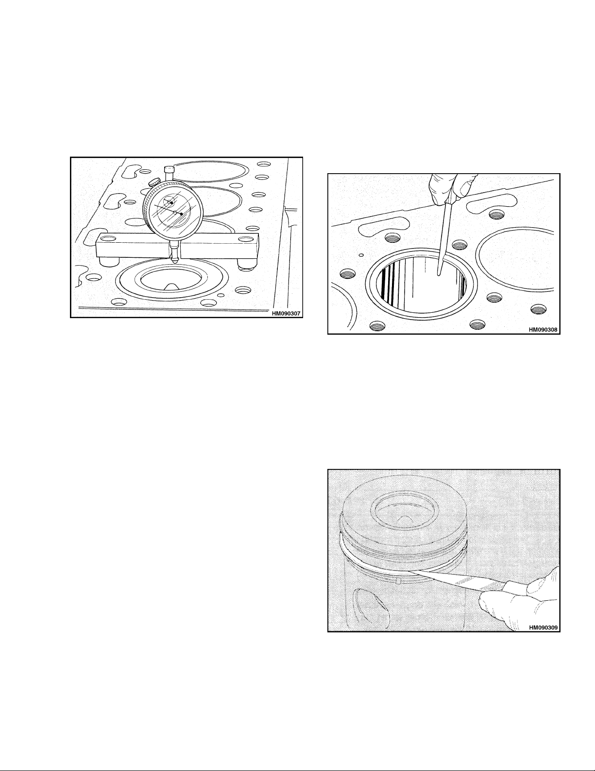
600 SRM 1068 Piston and Connecting Rod Assemblies Repair
height of the piston above the face of the engine
block. SeeFigure37.
The correct height of the piston above the engine
blockis0.36to0.50mm(0.014to0.020in.).The
tops of the pistons must not be changed or
machined.
Figure 37. Piston Height Above Engine Block
Measurement
11. Loosely assemble the bracket of the suction pipe
to the main bearing cap. Install a new gasket
and fasten the flanges of the suction pipe to the
oil pump. Verify that the suction pipe is aligned
correctly and tighten the capscrew that holds the
bracket to the main bearing cap.
12. Install the oil sump. See Oil Sump, Install.
13. Install the cylinder head. See Cylinder Head As-
sembly, Install.
2. Clean the carbon from the top of the cylinder lin-
ers. Fit the piston rings in the top part of the
cylinder liner and measure the clearance at the
endsofthering. SeeFigure38. Thespringmust
be installed in the oil control ring when its end
clearance is measured. The clearance measurements for the piston rings are shown in the Engine Specifications.
Figure 38. Piston Ring End Clearance Check
3. Install new piston rings on the piston and check
the clearance in the grooves with a spacer gauge.
SeeFigure39. Iftheclearancebetweenthepiston rings and the piston are greater than the
specifications, the piston must be replaced. See
the Engine Specifications. The clearance in the
top groove of the pistons for these engines cannot
be checked because it has a taper.
PISTON RINGS
Remove
1. Check that the piston rings can move freely in
their grooves and are not broken.
2. Remove the piston rings with a ring expander.
Increase the diameter of the piston rings only
enough to remove them without damaging the
piston.
Inspect
1. Check the piston for wear and damage.
Figure 39. Piston Ring Clearance Check
21
Page 30
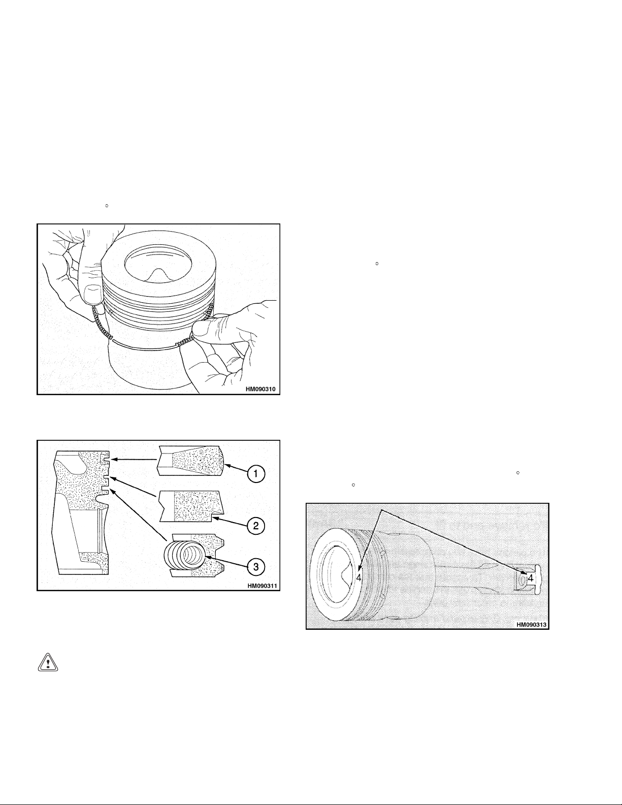
Piston and Connecting Rod Assemblies Repair 600 SRM 1068
Install
Install the piston rings with a ring expander. Increase the diameter of the piston rings only enough
to install them without damaging the piston.
1. Install the spring for the oil control ring in the
bottom groove of the piston. See Figure 40. Install the latch pin inside both ends of the spring.
See Figure 41. Install the oil control ring over
the spring so that the end space in the oil control
ring is 180
Figure 40. Spring Installation for Oil Control
to the latch pin.
Ring
ring is installed on the piston and the piston is
upright.
2. Install the cast iron ring with the taper into the
second groove of the piston. Verify that the word
TOP or the manufacturer’s symbol is toward the
topofthepiston.Newpistonringshaveagreen
identification mark which must be on the left of
the clearance at the ends of the ring when the
ring is installed on the piston and the piston is
upright.
3. Install the tapered (top ring) with the TOP to-
ward the top of the piston.
4. Check that the open gaps of the piston rings are
spaced 120
apart before installing the piston.
PISTON AND CONNECTING ROD
Disassemble
1. Remove the piston rings as described in Piston
Rings, Remove.
2. Make a mark on the piston to indicate the cylin-
der number as shown on the connecting rod.
Make the mark on the same side of the piston
as the number on the connecting rod. See Figure 42.
1. TOP RING
2. SECOND RING
Figure 41. Piston Rings Installation
3. OIL CONTROL
RING AND SPRING
CAUTION
Verify that the word TOP or the manufacturer’s symbol is toward the top of the piston.
New piston rings have a red identification
mark which must be on the left of the clearance space at the ends of the ring when the
3. Remove the snap rings that hold the piston pin in
the piston. Push the piston pin from the piston
with your thumb. If the piston pin is tight, heat
the piston and connecting rod to 40 to 50
to 122
F)to make removalof the piston pineasier.
Figure 42. Marking Piston
C(104
Inspect
1. Clean and inspect all the components for wear
and damage. Check the alignment of the connecting rod with a test mandrel. See Figure 43.
22
Page 31

600 SRM 1068 Piston and Connecting Rod Assemblies Repair
NOTE: The small end is wedge shaped. After the
small end bushing has been installed, machine the
bushing to the shape of the small end and remove
any sharp edges.
6. Machine the partially finished bushing to obtain
the correct connecting rod grade.
CAUTION
Do not use a letter stamp to mark the connecting rod.
7. Check that the grade letter on the connecting rod
NOTE: THE LARGE AND SMALL BORES IN THE
CONNECTING ROD MUST BE SQUARE AND PARALLEL WITH EACH OTHER WITHIN THE LIMITS OF
±0.25 mm (0.010 in.). THE MEASUREMENT IS MADE
AT127mm(5.0in.) ONEACHSIDEOFTHEAXIS
OF THE CONNECTING ROD. IF THE BUSHING IS
INSTALLED IN THE SMALL END OF THE CONNECTING ROD, THE LIMITS ARE REDUCED TO ±0.06 mm
(0.0025 in.).
is correct. If necessary, delete the letter and etch
a new letter on the side of the rod.
How to Select Correct Replacements
CAUTION
Itisimportantthatthepistondoesnotcontact the cylinder head. Ensure that the piston
height above the cylinder block is correct.
Figure 43. Connecting Rod Alignment Check
2. Check the clearance of the bushing in the con-
necting rod with the piston pin. If the clearance
is greater than 0.044 mm (0.0017 in.) or is damaged, install a new bushing.
NOTE: Connecting rod kits are available with a new
small-end bushing installed and finished to the correct grade. Refer to How to Select Correct Replacements to identify the correct rod grade.
A partially finished small-end bushing, which can be
installed intheoriginal connectingrod and machined
to obtain correct length grade, is also available.
3. If the bushing in the connecting rod is worn, use
a press to remove the bushing.
4. Clean the parent bore of the connecting rod and
remove any sharp edges.
CAUTION
Do not use a reamer to machine the partially
finished bushing. Special equipment and
trained personnel are needed.
Check that the connecting rods are fitted in
the correct cylinder. Record the position of the
connecting rod and its relevant cylinder when
it is removed from the engine.
To check that the piston height above the cylinder
block is correct, the engine may have up to six length
grades (F to L) of connecting rods fitted.
Identification of the length grade is by a letter or
color which is marked on the side of each connecting rod. See Figure 44. The letter F is the longest
grade of connecting rod and letter L is the shortest
grade. The difference between grades is 0.046 mm
(0.0018 in.).
5. Use a press to install a partially machined bush-
ing in the connecting rod. Verify that the lubrication hole in the bushing is aligned with the lubrication hole in the connecting rod.
1. CONNECTING ROD
Figure 44. Rod Bearings Position
23
Page 32

Piston and Connecting Rod Assemblies Repair 600 SRM 1068
If the grade letter or color on the side of the connecting rod cannot be seen, the length can be checked
by the measurement of the dimension (x) shown in
Figure 44. Before the length of the connecting rod
is measured, check that the bores of the big end and
the small end are square and parallel. See Figure 43.
The length is checked with the big end bearing removed and the original small end bush fitted. The
dimensions for each grade are listed in the table that
follows.
Length
Letter
F Red
H White
J Green
K Purple
L Blue
Color
Code
Length
165.728 to 165.761 mm
165.637 to 1
165.591 to 165.624 mm
165.545 to 165.578 mm
165.499 to
65.670 mm
165.532 mm
Install
1. Verify that the parts are clean. Lubricate the
parts with engine oil as they are assembled.
2. Install a new snap ring into one of the grooves to
hold the piston pin.
3. Turn the piston for access to install the connect-
ing rod. Install the connecting rod in position
in the piston. If the original piston is to be installed again, verify that the mark on the piston
is aligned with the mark on the connecting rod
as shown in Figure 42. Verify that the piston and
connecting rod are installed in the same cylinder
again.
4. If a new piston or connecting rod is being in-
stalled, verify that index slot in the connecting
rod for the rod bearing is on the same side of the
piston as the Iboss for the piston pin. See Figure 45.
1. INDEX SLOT FOR
BEARING
Figure 45. Piston and Connecting Rod
Orientation
5. Install the piston pin to fasten theconnecting rod
to the piston. If the piston pin is tight, heat the
piston to 40 to 50
lation of the piston pin easier.
6. Install the other snap ring to hold the piston pin
in the piston.
7. Install the piston rings as described in Piston
Rings, Install.
C (104 to 122 F) to make instal-
2. IBOSS FOR
PISTON PIN
PISTON COOLING JETS
Remove
Release the valve assembly and remove the piston
cooling jet. The crankshaft has been removed in Figure 46 to show the piston cooling jet.
24
Page 33

600 SRM 1068 Crankshaft Assembly Repair
3. Check the alignment of the cooling jet. Insert a
1.70 mm (0.067 in.) rod into the nozzle of the
cooling jet. The length of the rod must extend
outofthetopofthecylinder. Ifarodofthecorrect diameter is not available, grind one end of a
thicker rod to the 1.70 mm (0.067 in.) diameter
for a length of 16.00 mm (0.630 in.) so that it will
fit into the nozzle of the cooling jet. See Figure 47
for checking the alignment of the cooling jet.
1. ALIGNMENT DOWEL
Figure 46. Piston Cooling Jet
Install
1. Check that the ball assembly moves freely
against the spring pressure in the valve assembly and that the jet tube is not damaged. Replace
any damaged or worn parts.
2. Install the cooling jet. Verify that the assembly
is installed correctly on the alignment dowel in
the cylinder block. Tighten the valve assembly
to 27 N•m (21 lbf ft).
Figure 47. Piston Cooling Jet Alignment
Crankshaft Assembly Repair
GENERAL
The crankshaft is forged from chrome-molybdenum
steel. The center main bearing is the thrust bearing
that controls the axial movement of the crankshaft.
The thrust bearing has thrust washers on both sides
of the bearing. The main bearings are an alloy of tin
and aluminum. The center main bearing is a lead
and bronze alloy. The main bearing caps are made of
cast iron or spheroidal graphite (SG) iron. The front
and rear oil seals are lip seals with an additional dust
seal outside of the main lip and oil return grooves on
thefaceofthemainlip.
Thelocationofthefrontpulleyisbyakeyinthe
crankshaft nose and the pulley is held in position by
a tapered rings arrangement. See Figure 48.
1. CRANKSHAFT
PULLEY
Figure 48. Crankshaft Pulley Arrangement
2. VISCOUS DAMPER
3. TAPERED RING
25
Page 34

Crankshaft Assembly Repair 600 SRM 1068
These engines have a viscous damper which is fastened to the front or rear face of the pulley. See Figure 48. All dampers are designed for the suppression
of torsional vibrations in the engine crankshaft.
CRANKSHAFT PULLEY
Remove
1. Remove the drive belts.
2. Remove the three capscrews which hold the pul-
ley to the crankshaft. See Figure 49. Remove
the thrust block. If the crankshaft pulley will not
slide from the crankshaft, DO NOT use a puller
to remove the pulley. Hold a wood block against
the inner hub of the pulley and lightly hit the
wood block with a hammer. See Figure 50. This
action will loosen the inner ring and outer ring so
that the pulley can be removed from the crankshaft as shown in Figure 49.
See Figure 48. Check the area around the holes
for the damper fasteners for damage.
Figure 50. Crankshaft Pulley Installation
Install
1. Install the damper in position on the face of
the pulley. For rear-mounted dampers, tighten
the M10 Allen screws to 65 N•m (48 lbf ft) and
the M8 Allen screws to 35 N•m (26 lbf ft). For
front-mounted dampers, tighten the M12 bolts
to 78 N•m (58 lbf ft).
1. SPACER RING
2. INNER RING
3. OUTER RING
Figure 49. Crankshaft Pulley Arrangement
4. THRUST BLOCK
5. O-RING
Inspect
1. Check the area around the holes for the damper
fasteners, for cracks or wear. Replace the pulley
if cracks or wear are found.
2. The viscous damper must be renewed if there is
impact damage to the outer casing or if there is
leakage of the viscous fluid from the cover plate.
2. Clean the end of the crankshaft and the parts
of the crankshaft pulley. Do not use a degreasing solution. See Figure 49. Do not make any
changes to the inner ring or the outer ring.
3. Put the crankshaft pulley on the crankshaft so
that the key is engaged. Push the pulley onto the
crankshaft.
NOTE: If the rings are not installed correctly, the
crankshaft pulley will be very difficult to remove
again.
4. Install the spacer ring, inner ring, and the outer
ring in the correct order.
5. Lightly lubricate the O-ring and the thrust faces
of the capscrews with engine oil. Put the thrust
block and the capscrews in position.
6. Gradually and evenly tighten the capscrews to
push the crankshaft pulley on the crankshaft.
Tighten the capscrews to 115 N•m (85 lbf ft).
7. Install the drive belts. See Drive Belts.
26
Page 35

600 SRM 1068 Crankshaft Assembly Repair
REAR OIL SEAL
Special Tools: Seal alignment tool
Oilsealreplacementtool
Remove
1. Remove the drive components from the rear of
the engine.
2. Remove the flywheel and housing. See Flywheel,
Remove.
3. Remove the capscrews and remove the seal hous-
ing and seal assembly. Clean the parts.
4. Inspect the oil seal for wear and damage. If there
is any question about the condition of the oil seal,
replace the oil seal.
5. Check that the oil seal area and outer circum-
ference of the crankshaft flange are not worn or
damaged.
6. Press the oil seal from the housing. Discard the
oil seal.
Install
CAUTION
To prevent contamination, do not open the new
rear oil seal assembly until required for use.
1. Verify that the crankshaft flange, rear of the
cylinder block, and bridge piece are clean and
dry.
3. Install the new gasket on the seal housing. Put
the oil seal and housing on the seal guide. Carefully push the oil seal assembly into position on
the crankshaft flange. See Figure 51.
1. SEAL GUIDE
2. OIL SEAL AN
3. GASKET
Figure 51. Oil Seal Installation
4. Remove theseal guideandrotate the rearoilseal
to align the holes of the rear oil seal assembly
with the holes in the cylinder block and the cylinder block bridge piece.
5. Install the capscrews but do not tighten.
NOTE: The seal alignment tool is not available at
this time. The tool must be manufactured locally. It
must be made from material EN32 and outer surfaces knurled. Verify that all sharp edges are removed. SeeFigure52.
DHOUSING
CAUTION
Do not use lubricant on the crankshaft flange
or the rear oil seal, as the seal is prewaxed.
2. Open the new rear oil seal assembly and verify
that the seal guide is aligned within the rear oil
seal.
CAUTION
The seal guide must be in place when the rear
oil seal is installed on the crankshaft flange to
prevent damage to the seal.
6. Put the seal alignment tool on the crankshaft
flange and over the rear oil seal housing. Align
the rear oil seal with the crankshaft flange.
7. Torque capscrews (1 and 2) to 22 N•m (16 lbf ft).
SeeFigure53.
8. Remove the seal alignment tool. Torque remaining capscrews in sequence to 22 N•m (16 lbf ft).
9. Install flywheel and housing. See Flywheel, Install.
10. Install rear drive components.
27
Page 36

Crankshaft Assembly Repair 600 SRM 1068
Figure 52. Seal Alignment Tool
wrench can be required to apply the correct torque
to the capscrews for removal and installation. If
a wrench is not available to install the capscrews
on the main bearing cap, the timing case must be
removed. The oil pump will be removed with the
cap for the front main bearing. The suction pipe,
oil strainer, delivery pipe, and relief valve must be
removed.
Figure 53. Oil Seal Housing Torque Sequence
MAIN BEARINGS
NOTE: The following procedure is for replacement of
the main bearings without removing the crankshaft
from the engine.
If the rear main bearing must be replaced, the flywheel, flywheel housing, rear oil seal housing, and
bridge piece must be removed.
The front main bearing can be difficult to replace
when the timing case is on the engine. The oil
pump is installed on the front bearing cap. A special
Remove
1. Drain the engine oil and remove the oil sump.
2. Remove the necessary components for access to
the bearing cap for the bearing that must be replaced.
3. Remove the capscrews and remove the bearing
cap. Remove the lower half of the bearing from
the bearing cap.
4. Use a thin flexible tool to push on the side of the
upper bearing half that is opposite from the location tab. Push on the bearing half so that it begins to rotate out of the engine block. Carefully
rotate crankshaft so that bearing will rotate out
oftheengineblock.
5. Check that the bearing journal on the crankshaft
is clean and in good condition. See Figure 54.
28
Page 37

600 SRM 1068 Crankshaft Assembly Repair
4. Verify the capscrews are in good condition. Install the capscrews into the bearing cap. Tighten
the capscrews gradually and evenly. Tighten
the capscrews to a final torque of 265 N•m
(195 lbf ft).
5. Verify that the crankshaft rotates freely. If the
thrust washers have been removed and installed
again, the axial movement of the crankshaft
must be checked. See Thrust Washers.
6. Install the components that were removed for access to the main bearing.
7. Installtheoilsump.
1. BEARING
REMOVAL TOOL
Figure 54. Main Bearing Removal
2. LOCATION SLOTS
3. BEARING GROOVE
Inspect
Inspect the bearings for wear and other damage. If
a bearing is worn or damaged, replace both halves
of the shell bearings and check the condition of the
other bearings.
Install
NOTE: Only the upper half of the bearing has lubri-
cation holes and it must be installed into the engine
block.
1. Lubricate the upper bearing half with engine oil.
Install the plain end of the bearing between the
crankshaft journal and the side of the bearing
housing that has the location slot. Carefully slide
the bearing half into the bearing housing until
the location tab fits into the location slot.
2. Lubricate the lower bearing half with engine oil
and install it into the bearing cap. Verify the
location tab is installed correctly into the location
slot.
3. Verify that the location thimbles are installed in
either the bearing cap or the bearing housing of
the engine block. Verify that the orientation of
the location slots for the bearing halves is correct
as shown in Figure 55. Install the bearing cap.
1. LOCATION SLOTS FOR MAIN BEARING HALVES
Figure 55. Main Bearing Cap Orientation
THRUST WASHERS
Crankshaft Axial Movement, Check
The axial movement of the crankshaft is controlled
by two half thrust washers, one installed on each
side of the center main bearing. See Figure 56. The
axial clearance can be checked with a spacer gauge
inserted between the crankshaft and the thrust
washer. See Figure 57. A dial indicator can be used
to check the axial movement from the end of the
crankshaft as shown in Figure 58. The normal axial
movement is 0.05 to 0.38 mm (0.002 to 0.015 in.).
The maximum axial movement permitted is 0.51 mm
(0.020 in.).
29
Page 38

Crankshaft Assembly Repair 600 SRM 1068
If the axial movement is greater than the specifications, oversize thrust washerscanbeinstalled on one
side or both sides of the main bearing. The oversize
thrust washers are 0.019 mm (0.00075 in.) larger
than the standard thrust washers.
Remove
1. Drain the engine oil from the sump. Remove the
oil sump. See Oil Sump, Remove.
2. Remove the suction pipe and oil strainer. See
Figure 31. Remove the capscrew that holds the
bracket to the main bearing cap. Remove the two
capscrews from the flange of the suction pipe and
Figure 56. Thrust Washers
remove the suction pipe and screen. Clean the
faces of both flanges.
3. Remove the capscrews for the center main bear-
ing cap. Remove the bearing cap, lower bearing
half, and the lower halves of the thrust washers.
4. Use a thin flexible tool to push the upper halves
of the thrust washers from their positions next
to the main bearing housing. See Figure 59. Use
a small pry bar as necessary to move the crankshaft to loosen a tight thrust washer.
Figure 57. Axial Clearance Measurement With
Spacer Gauge
Figure 58. Axial Movement Measurement With
Dial Indicator
30
Figure 59. Thrust Washer Upper Half Removal
Install
1. Lubricate the thrust washers with engine oil.
Slide the upper halves of the thrust washers into
their positions in the engine block. Verify that
the sides of the thrust washers with the grooves
are against the crankshaft.
2. Install the lower halves of the thrust washers
into the main bearing cap. Verify that the location tabs are in their correct positions.
Page 39

600 SRM 1068 Crankshaft Assembly Repair
3. Verify that the location thimbles are installed in
either the bearing cap or the bearing housing of
the engine block. Verify that the orientation of
the location slots for the bearing halves is correct
as shown in Figure 55. Lubricate the bearing
and thrust washers with engine oil. Install the
bearing cap.
4. Inspect the capscrews and reuse if in good
condition. Install the capscrews into the bearing cap. Tighten the capscrews gradually and
evenly. Tighten the capscrews to a final torque
of 265 N•m (195 lbf ft).
5. Verify that the crankshaft rotates freely. Check
the axial movement of the crankshaft to verify
that it is within the specifications.
6. Loosely assemble the bracket of the suction line
to the main bearing cap. Install a new gasket
and fasten the flanges of the suction line to the
oil pump. Verify that the suction line is aligned
correctly and tighten the capscrew that holds the
bracket to the main bearing cap.
7. Install the oil sump. See Oil Sump, Install.
CRANKSHAFT
10. Remove the rear oil seal housing. See Rear Oil
Seal, Remove.
11. If the engine is not already in a position with the
crankshaftfacingup,turntheenginetothatposition. Remove the suction pipe and oil strainer.
SeeFigure31. Removethecapscrewthatholds
the bracket to the main bearing cap. Remove the
two capscrews from the flange of the suction pipe
and remove the suction pipe and screen. Clean
the faces of both flanges. Remove the oil pump,
delivery tube, and relief valve. See Oil Pump and
Relief Valve.
12. Removethebridgepieceovertherearmainbear-
ing. Make a note if there is a round rubber seal
at each end of the bridge piece where it joins the
crankcase. Some engines have rubber seals and
other engines have sealant.
13. Remove the bearing caps and lower bearing
halves from the connecting rods. Make an arrangement so that the parts for each connecting
rod will be assembled again in their original
positions. Carefully push the pistons into their
bores a small amount so that the connecting rods
are separated from the crankshaft.
Remove
1. Remove the engine from the lift truck. See the
Frame section. See the Transmission section
for separating the engine from the transmission.
2. Remove the oil sump. See Oil Sump, Remove.
3. Remove the fan, drive belts, fan drive pulley and
housing, and coolant pump.
4. Remove the crankshaft pulley. See Crankshaft
Pulley.
5. Remove the alternator and its mount bracket.
6. Remove the timing case cover. See Timing Case
Cover, Remove.
7. Remove the fuel injection pump. See Fuel Injection Pump, Remove.
8. Remove the timing gears and the timing case.
See Timing Case and Timing Gears Repair.
9. Remove the flywheel and the flywheel housing.
See Flywheel, Remove.
CAUTION
Verify the cooling jets for the pistons are not
damaged or moved out of alignment. If a cooling jet is hit, the alignment must be checked
and the cooling jet replaced if necessary.
14. Verify that each main bearing cap is are marked
with their position number. Remove the main
bearing caps, lower bearing halves, and the upper and lower thrust washers. Keep all the parts
in an arrangement so that the parts can be installed in their original positions.
15. Lift the crankshaft from the cylinder block. Re-
move the upper bearing halves and put each of
them with its lower bearing half.
Inspect
Check the crankshaft for wear and other damage.
The maximum wear and out-of-round on the bearing
journals is 0.04 mm (0.0016 in.). See Table 20.
31
Page 40

Crankshaft Assembly Repair 600 SRM 1068
The bearing journals on standard crankshafts can be
ground to the following diameters smaller than the
original size:
0.25 mm (0.010 in.)
0.51 mm (0.020 in.)
0.76 mm (0.030 in.)
Special bearings are available for these sizes.
The crankshaft must be replaced if the surface must
be ground more than 0.76 mm (0.030 in.).
The area onthe crankshaftflange for the rear oil seal
canbemachinedtoremovewearmarks. SeetheEngine Specifications. The minimum diameter of this
area is 133.27 mm (5.247 in.).
Install
1. Verify that all of the oil passages are clean.
2. Verify all of the bearings and bearing caps are
clean. Install the upper bearing halves into their
positions in the connecting rods and the housings
for the main bearings. Verify that the position
tags of the bearings fit into their position slots.
Lubricate the bearings with engine oil.
as the number on the bottom face of the engine
block. (The third and fifth bearing caps are not
marked with a serial number.)
8. Inspect the capscrews and reuse if in good condi-
tion. Install the capscrews into the main bearing cap. Tighten the capscrews gradually and
evenly. Tighten the capscrews to a final torque
of 265 N•m (195 lbf ft). Repeat this step for all
five main bearings.
9. When the bridge piece is put into position, inject
liquid gasket sealant (Loctite
®
5900) into the uppergrooveateachendofthebridgepiece. See
Figure 60. Inject the sealant until the upper
groove is full and the sealant leaves the lower
groove at the front and rear of the bridge piece.
Verify all of the grooves are completely full of
sealant.
3. Install the crankshaft in position on the main
bearings.
4. Lubricate the thrust washers with engine oil.
Slide the upper halves of the thrust washers into
their positions in the engine block. Verify that
the sides of the thrust washers with the grooves
are against the crankshaft.
5. Install the lower halves of the thrust washers
into the main bearing cap. Verify that the location tags are in their correct positions.
6. Verify that the location thimbles are installed in
either the bearing cap or the bearing housing of
the engine block. Verify that the orientation of
the location slots forthe bearing halvesis correct,
as shown in Figure 55. Lubricate the bearing
and thrust washers with engine oil. Install the
bearing cap.
7. Verify the main bearing caps are installed ac-
cording to their position numbers shown on the
cap. The serial numbers on the main bearing
caps will also be in alignment. The serial number on the main bearing caps must be the same
1. LOWER G
Figure
10. Use a st
d with the rear face of the engine block.
aligne
See Fig
(12 lbf
11. Instal
Rod Be
half i
catio
in the
the as
same
that
side
ure 61. Tighten the capscrews to 16 N•m
ft).
l the connecting rods tothecrankshaft. See
arings, Install. Install the upper bearing
nto the connecting rod. Verify that the lo-
n tab is installed correctly into its position
connecting rod. See Figure 32. Verify that
sembly number on the bearing cap is the
as the numberonthe connectingrod. Verify
the two assembly numbers are on the same
of the connecting rod as shown in Figure 33.
ROOVE
2. UPPER G
ROOVE
60. Bridge Piece and Sealant
raightedge to verify the bridge piece is
32
Page 41

600 SRM 1068 Crankshaft Assembly Repair
FLYWHEEL
The steel flywheel has a hardened steel starter ring.
The starter ring has 126 teeth.
Remove
1. Removetwooppositecapscrewsfromthefly-
wheel and temporarily install two studs to help
control the flywheel when the other capscrews
are removed.
2. Remove the other capscrews that fasten the fly-
wheel to the crankshaft. Remove the flywheel.
Figure 61. Bridge Piece Alignment
12. Install and tighten the nuts evenly to a torque of
125 N•m (92 lbf ft). Verify that the crankshaft
turns freely.
13. Install the oil pump, delivery pipe, and relief
valve. Loosely assemble the bracket of the suction pipe to the main bearing cap. Install a new
gasket and fasten the flanges of the suction line
to the oil pump. Verify that the suction pipe is
aligned correctly and tighten the capscrew that
holds the bracket to the main bearing cap.
14. Install the rear oil seal housing. See Rear Oil
Seal, Remove.
15. Install the flywheel and the flywheel housing.
See Flywheel, Install.
16. Install the timing gears and the timing case. See
Timing Case and Timing Gears Repair.
17. Install the fuel injection pump. See Fuel Injec-
tion Pump, Install.
18. Install the timing case cover. See Timing Case
Cover, Install.
19. Install the alternator and its mount bracket.
20. Install the crankshaft pulley. See Crankshaft
Pulley.
21. Install the coolant pump, fandrivepulley and fan
housing, drive belts, and the fan.
3. Check the flywheel and ring gear for damage.
Ring Gear, Replace
WARNING
Wear eye protection for this operation to prevent eye injury from metal chips. You will be
using a hammer and chisel to break the ring
gear.
1. Before the ring gear is removed, check the posi-
tion of the chamfer on the teeth.
2. Use a hammer and chisel to break the ring gear.
Make sure that you do not damage the flywheel.
3. The ring gear must be heated before it can be
installed on the flywheel. Use an oven that has
a temperature control. Verify that the ring gear
is not heated to more than 250
4. Verify that the chamfer on the ring gear teeth is
in the correct direction. Install the ring gear on
the flywheel.
C(482F).
Install
1. Verify the surfaces of the crankshaft and fly-
wheel are clean so that the two parts will fit
together correctly.
2. Install the flywheel over the guide studs. Install
four capscrews. Remove the two studsand install
the remainder of the capscrews. Tighten the capscrews in a cross pattern to 107 N•m (78 lbf ft).
22. Install the oil sump. See Oil Sump, Install.
23. Install the engine into the lift truck. See the
Frame section and the Transmission section
for the lift truck.
3. Check the flywheel runout with a dial test in-
dicator. See Figure 62. This must be less than
0.30 mm (0.012 in.) total indicator reading.
33
Page 42

Crankshaft Assembly Repair 600 SRM 1068
4. Check the alignment of the flywheel face. See
Figure 63. The error in alignment must not be
more than 0.003 mm (0.0001 in.) total indicator
reading for every 25 mm (1.0 in.) of the flywheel
radius from the crankshaft axis to the indicator
plunger. During this check, keep the crankshaft
pressed toward the front to remove the effect of
crankshaft end-float.
Figure 62. Flywheel Run-Out Check
1. Remove the starter.
2. Remove the flywheel. See Flywheel, Remove.
3. Release the housing setscrews and with a soft
face hammer, carefully hit the housing to remove
it from the dowels.
Install
1. Ensure that the rear face of the cylinder block
and the faces of the housing are clean and free
from damage. Ensure that the location dowels
are fitted correctly. If a felt seal is installed to
the rear flange of the sump, replace the seal.
2. Fit the housing onto the dowels and lightly
tighten the setscrews.
3. Check the housing concentricity with a dial test
indicator. See Figure 64. The runout limit is
given in the data and dimensions. If any adjustment is necessary, it must be made on the housing, and the concentricity checked again.
Figure 63. Flywheel Face Alignment
FLYWHEEL HOUSING
Remove
WARNING
The fl
ment o
befor
ers.
34
ywheel housing is heavy. Use lift equip-
r get help to assist with theliftoperation
e removal of the flywheel housing fasten-
Figure 64. Flywheel Housing Concentricity
Check
4. Tighten the setscrews to the torque recom-
mended in the Special Torque Specifications.
5. Check the housing alignment. See Figure 65.
The maximum tolerance is given in the data and
dimensions. Any necessary adjustment must be
made on the housing and not on the cylinder
block.
6. Install the flywheel and the starter motor.
Page 43

600 SRM 1068 Timing Case and Timing Gears Repair
Figure 65. Flywheel Housing Alignment Check
Timing Case and Timing Gears Repair
GENERAL
The timing case can be either cast aluminum or cast
iron. The timing gears are steel.
The gear train includes the crankshaft gear, idler
gear, gear for the fuel injection pump, camshaft gear,
and PTO gear. The timing case cover is aluminum
and has the front oil seal for the crankshaft. The timing case cover has a noise shield on its front surface.
SeeDescriptionforadditionalinformationontiming
gears and engine timing.
The camshaft is made from cast iron. The lobes on
the camshaft for the fuel pump are hardened.
TIMING CASE COVER
Remove
1. Drain the coolant. Remove the fan. See Figure 66.
2. Remove the drive belts and alternator.
3. Remove the crankshaft pulley. See Crankshaft
Pulley.
4. Remove the fan drive pulley if additional clearance is needed.
5. Remove the coolant pump. See Coolant Pump,
Remove.
1. CAPSCREW
2. CYLINDER BLOCK
3. STUD
Figure 66. Timing Case Cover
4. GASKET
5. TIMING CASE
COVER
35
Page 44

Timing Case and Timing Gears Repair 600 SRM 1068
6. Remove the capscrews and nuts that hold the
timing case cover to the timing case. Remove the
timing case cover and the sound shield.
Install
Special Tools: Alignment tool, front oil seal
1. Use
a new gasket and install the timing case
er on the timing case. See Figure 66. Use
cov
capscrews to hold the timing case cover in
two
sition. Install the special tool on the crank-
po
aft. Use the special washer and the capscrews
sh
r the crankshaft pulley to hold the alignment
fo
ol in position. The purpose of the special tool is
to
verify that the front oil seal evenly fits the cir-
to
umference of the seal surface of the crankshaft
c
ulley. SeeFigure67.
p
6. Install the alternator and drive belts and adjust
the tension. See Drive Belts.
7. Install the fan. Fill the cooling system.
FRONT OIL SEAL
Remove
1. Remove the fan and drive belts.
2. Remove the crankshaft pulley.
3. Use a pry bar to remove the front oil seal from
the timing gear cover. Put the pry bar behind
the main lip of the front oil seal. Verify that the
edge of the housing fortheoilseal isnot damaged
during removal.
Install
Special Tools: Installation tool for front oil seal
Pressure plate
Fastener plate
Sleeve
Seal adapter
Figure 67. Front Oil Seal Alignment Tool
CAUTION
The correct alignment of the timing case cover
is important and must be done carefully. The
front oil seal can leak and the gears for the
coolant pump can fail if the alignment is not
correct.
2. When the timing case cover is aligned with the
crankshaft, install the capscrews and nuts in the
timing case cover. Tighten the capscrews and
nuts to 22 N•m (16 lbf ft). Remove the alignment
tool.
3. Install the coolant pump. See Coolant Pump, In-
stall.
4. Install crankshaft pulley. See Crankshaft Pulley.
TE: The front oil seal is normally installed to a
NO
epth of 10.20 to 10.70 mm (0.402 to 0.421 in.) from
d
he front face of the oil seal housing to the flat front
t
ace of the oil seal. If the crankshaft pulley is worn
f
t this location, a wear sleeve can be installed. See
a
igure 69.
F
lean the oil seal housing. Inspect the oil seal for
1.C
damage. Do not install a front oil seal that has a
scratch or any damage on the lip of the seal.
2. Lubricate the outer circumference of the oil seal
with engine oil and install the front oil seal into
the oil seal housing. Verify that the lip of the seal
is toward the inside of the cover for the timing
gear case and the front oil seal is parallel to the
bore of the oil seal housing.
3. Put the replacement tool for the front oil seal on
the crankshaft as shown in Figure 68. Use the
fastener plateto fasten the installation tool tothe
crankshaft. Install the seal adapter so the 10.5
mm mark is toward the front oil seal. Put the
sleeveandthepressureplateintopositionand
fasten ittothe studof thefastener plate asshown
in Figure 68.
5. Install the fan drive pulley if it was removed.
36
Page 45

600 SRM 1068 Timing Case and Timing Gears Repair
A new front oil seal must be used when a wear
sleeve is fitted.
The dimension to press the new oil seal into the
timing case, with or without a wear sleeve fitted,
is 9.3 mm (0.366 in.), from the front face of the
timing case.
3. Install the crankshaft pulley. See Crankshaft
Pulley, Install.
1. REPLACEMENT
TOOL FOR FRONT
OIL SEAL
2. PRESSURE PLATE
Figure 68. Front Oil Seal Installation
4. Installarodthroughtheholeintheendofthe
tool so the tool will not turn. Turn the nut on the
pressure plate with a wrench and the front oil
seal will be pushed into the housing. Push the
seal into the correct depth. Remove the installation tool.
5. Lubricate the seal area of the crankshaft pulley
with engine oil. Install the crankshaft pulley.
See Crankshaft Pulley.
6. Install the drive belts and adjust the belt tension.
7. Install the fan.
3. FASTENER PLATE
4. SLEEVE
5. SEAL ADAPTER
CRANKSHAFT PULLEY WEAR SLEEVE
Install
To renew a worn crankshaft pulley, a wear sleeve is
fitted over the spigot. See Figure 69.
1. Remove the crankshaft pulley. See Crankshaft
Pulley, Remove.
1. SPIGOT
2. WEAR SLEEVE
Figure 69. Crankshaft Pulley Wear Sleeve
3. FLANGE
4. OIL SEAL
IDLER GEAR AND HUB
Remove
1. Remove the timing case cover. See Timing Case
Cover, Remove.
2. Turn the crankshaft until the marked teeth of
the crankshaft gear, the camshaft gear, and the
gear for the fuel injection pump are aligned as
showninFigure70. Themarkedteethonthe
idler gear will not necessarily be aligned with the
marked teeth of the other three gears because of
the different speed of rotation of the idler gear.
NOTE: Full instructions and a special tool to install
the wear sleeve are in each service kit.
2. Install the wear sleeve in accordance with the
manufacturer’s instructions.
It is not necessary to remove the flange of the
wear sleeve after it has been fitted.
CAUTIO
Verify that the crankshaft is not turned while
the idler gear is removed. A piston can hit and
damage a valve. The valve timing and the fuel
injection pump timing will be lost if the crankshaft is turned.
3. Remove the three capscrews, the plate of the
idler gear, and the idler gear. See Figure 71.
N
37
Page 46

Timing Case and Timing Gears Repair 600 SRM 1068
Make a note of the position of the oil hole. The
gear for the fuel injection pump will turn a small
amount in the counterclockwise direction as the
teeth become disengaged from the idler gear.
1. CAMSHAFT GEAR
2. CRANKSHA
GEAR
3. IDLER GEAR
Figure 70. Timing Marks Alignment
FT
4. GEAR FOR FUEL
INJECTIO
5. PTO GEAR
NPUMP
bushings and use a press to remove them from
the idler gear. Use a press to install new bushings. The bores and faces of the bushings will
need machining to correctly fit the hub. See the
Engine Specifications for the measurements.
Install
1. Usethethreecapscrewsfortheidlergeartover-
ify that the hub for the idler gear is in the correct
position, with the lubrication hole at the top.
2. Lubricate the bushings in the idler gear with en-
gine oil. Align the timing marks on the idler
gear with the marks on the crankshaft gear and
the camshaft gear. Turn the gear for the fuel injection pump clockwise as necessary to align the
timing marks when the teeth of the idler gear engage the other gears. Verify all of the alignment
marks are aligned as shown in Figure 70.
3. Install the plate for the idler gear and the three
capscrews. Tighten the capscrews to 44 N•m
(32 lbf ft).
4. Check the clearance between the bushings of the
idler gear and the plate of the idler gear. The
correct clearance is 0.10 to 0.20 mm (0.004 to
0.008 in.). A maximum service limit is 0.38 mm
(0.015 in.). See Figure 72.
1. PLATE
2. THRUST
3. IDLER GEAR
4. TIMING MARKS
5. HUB
4. Inspec
damage
able as
5. If the b
to remo
is not a
38
WASHER
Figure
71. Idler Gear Components
ttheidlergearandbushingsforwearand
. The idler gear and bushings are avail-
an assembly or as separate parts.
ushings must be replaced, use a puller
ve them from the idler gear. If a puller
vailable, grind one of the faces from the
6. OIL HOLE
7. REAR TH
WASHER
8. CAPSCREW
RUST
Figure 72. Idler Gear Hub Clearance Check
5. Check the timing gear clearances as shown in
Figure 75. The minimum clearances for all gears
is 0.08 mm (0.003 in.).
6. Install the timing case cover, coolant pump,
crankshaft pulley, fan drive pulley, drive belts,
and fan. See Timing Case Cover, Install.
Page 47

600 SRM 1068 Timing Case and Timing Gears Repair
AIR COMPRESSOR DRIVE, BENDIX
Disassemble
CAUTION
Do not turn the engine crankshaft or the
crankshaft for the air compressor. If either
crankshaft is moved, the air compressor must
be timed to the engine.
1. Set the number one piston to TDC as described
in the Engine Timing section.
2. Remove the timing case cover as described in
Timing Case Cover, Remove.
3. Remove the three capscrews shown. See Fig-
ure73.Removethecoverplate. Removetheidler
gear and the needle bearings from the idler hub.
1. TIMING CASE
2. BRACKET, IDLER
HUB
Figure 74. Bendix Compressor Drive
3. CAPSCREWS (3)
4. CAPSCREWS (4)
5. IDLER GEAR
Assemble
1. O-RING
2. CAPSCREW
3. BRACKET
4. DRIVE GEAR, AIR
COMPRESSOR
5. TIMING CASE
6. COVER, TIMING
CASE
Figure 73. Bendix Compressor Drive
4. Remove the three capscrews which fasten the
idler hub to the bracket. Remove the idler gear
hub. See Figure 74.
5. Remove and discard the O-ring. See Figure 73.
6. Inspect the parts for wear or damage.
7. NEEDLE BEARING
8. CAPSCREW (3)
9. IDLER HUB
10. COVER PLATE
11. IDLER GEAR
12. ENGINE IDLER
GEAR
1. Install the O-ring. See Figure 73.
2. Check that the four capscrews (4) which fasten
the idler hub bracketto the timing case are tightened to 35 N•m (26 lbf ft). See Figure 74.
3. Install the hub into the timing case. See Fig-
ure 73 and Figure 74. Install the three capscrews
and tighten them to 60 N•m (44 lbf ft). Install
theneedlebearingassemblyonthehub.
4. Lubricate the bore of the idler gear with clean
engine oil and install the idler gear on the needle
bearings. See Figure 73. Install the cover plate
and tighten three capscrews to 22 N•m (16 lbf ft).
5. Check the clearance between the bushings of the
idler gear and the plate of the idler gear. The
correct clearance is 0.10 to 0.20 mm (0.004 to
0.008 in.). A maximum service limit is 0.38 mm
(0.015 in.). See Figure 72.
6. Check the timing gear clearances as shown in
Figure 75. The minimum clearance is 0.08 mm
(0.003 in.).
7. Install the timing case cover as described in Tim-
ing Case Cover, Install.
39
Page 48

Timing Case and Timing Gears Repair 600 SRM 1068
Do not loosen or remove the large nut from the
shaft of the fuel injection pump. The hub is permanently fastened to the shaft. If the hub is removed, special equipment and special training
is required to correctly install the hub again.
Special Tools: Bosch fuel injection pump timing
pin
Figure 75. Timing Gear Clearances Check
FUEL INJECTION PUMP GEAR
The fuel injection pump has a timing plate fastened
to the front face of the gear for the fuel injection
pump. See Figure 76. This timing plate is installed
by the manufacturer after the fuel injection timing
has been accurately set to TDC, number one cylinder
on the compression stroke. The timing plate is fastened by two M5 special capscrews.
1. Rem
ove the timing case cover. See Timing Case
ver, Remove.
Co
CAUTION
ify the shaft of the fuel injection pump is not
Ver
cked.
lo
t the number one piston to TDC on the com-
2. Se
ession stroke. Turn the crankshaft until
pr
e marked teeth of the crankshaft gear, the
th
mshaft gear, and the gear for the fuel injection
ca
mp are aligned as shown in Figure 76. The
pu
arked teeth on the idler gear will not neces-
m
arily be aligned with the marked teeth of the
s
ther three gears because of the different speed
o
f rotation of the idler gear.
o
CAUTION
DO NOT turn the crankshaft while removing
the camshaft gear. A pistoncanhit and damage
a valve.
3. Install the timing pin until the small end of the
pin is pushed fully into the hole in the body of the
fuel injection pump. See Figure 77.
1. M5 SPECIAL
CAPSCREWS
Figure 76. Fuel Injection Pump Gear Removal
2. TIMING PLATE
3. CAPSCREWS (4)
Remove
CAUTION
Do not loosen the two M5 special capscrews. If
this timing plate is moved, the fuel injection
pump must be timed again.
40
4. Remove the four capscrews from the fuel pump
gear and remove the gear from the hub.
5. Inspect the gear for wear and damage, and re-
place if necessary.
1. TIMING PIN
Figure 77. Fuel Injection Pump Gear Removal
Page 49

600 SRM 1068 Timing Case and Timing Gears Repair
Install
CAUTION
Verify the shaft of the fuel injection pump is not
locked.
1. The gear for the fuel injection pump can only be
installed in one position. The letters C and M are
toward the front of the engine. Verify the number one piston is set to TDC on the compression
stroke.
2. If the timing pin was removed during service, in-
stall it in the hole in the body of the fuel injection
pump. See Figure 78. Leave the timingpinin position so that the gear for the fuel injection pump
can be installed.
4. Install the four capscrews loosely in the centers
of the slots of the gear.
NOTE: If a new gear is installed, carefully rotate the
gear counterclockwise to remove any clearance between the gear and the idler gear. See Figure 77.
Do not rotate the crankshaft or it will be necessary
to set TDC again.
5. Tighten the four capscrews to 28 N•m (21 lbf ft).
Remove the timing pin from the fuel injection
pump.
6. If a new gear has been installed, check the clear-
ance as shown in Figure 75.
7. Install the timing case cover, coolant pump,
crankshaft pulley, fan drive pulley, drive belts,
and fan. See Timing Case Cover, Install.
CAMSHAFT GEAR
Remove
Special Tools: Gear puller with adapters
1. GEAR FOR FUEL
INJECTION PUMP
Figure 78. Fuel Injection Pump Gear
Installation
3. Install the gear for the fuel injection pump over
the timing pin so that it engages correctly with
the idler gear.
NOTE: If a new gear is installed, install the original
timing plate onto the front face of the new gear. Install the two M5 special capscrews loosely and install
the gear on the hub. If the gear and timing plate are
installed correctly, the four threaded holes in the hub
can be seen through the slots in the gear.
2. IDLER GEAR
3. TIMING PIN
emove the timing case cover. See Timing Case
1.R
over, Remove.
C
urn the crankshaft until the marked teeth of
2.T
he crankshaft gear, the camshaft gear, and the
t
ear for the fuel injection pump are aligned as
g
hown in Figure 79. The marked teeth on the
s
dler gear will not necessarily be aligned with the
i
marked teeth of the other three gears because of
the different speed of rotation of the idler gear.
CAUTION
Verify that the crankshaft is not turned while
the camshaft gear is removed. A piston can hit
and damage a valve.
3. Remove the capscrew and washer. Use a puller
and adapter to pull the gear from the camshaft.
Make sure that the woodruff key in the camshaft
is not lost. Inspect the camshaft gear for wear
and damage. See Figure 80.
41
Page 50

Timing Case and Timing Gears Repair 600 SRM 1068
3. Install the camshaft gear on the shaft with the
marked teeth toward the front and the keyway
correctly aligned. Use a soft hammer to push the
gear onto the camshaft. Verify that the timing
marks are aligned correctly as the gear teeth are
engaged. See Figure 79.
4. Install the idler gear with the marked teeth cor-
rectly aligned. See Idler Gear and Hub, Install.
If the camshaft has to be turned and a valve hits
a piston, disengage the rocker assembly.
5. Install the capscrew and washer and tighten the
capscrew to press the gear into position. Tighten
thecapscrewto95N•m(74lbfft).
1. CAMSHAFT GEAR
2. CRANKSHAFT
GEAR
3. IDLER GEAR
Figure 79. Timing Marks Alignment
4. GEAR FOR FUEL
INJECTION PUMP
5. PTO GEAR
6. If new gears have been installed, check the tim-
ing gear clearances as shown in Figure 75. The
minimum clearances for all gears is 0.08 mm
(0.003 in.).
7. Install the timing case cover, coolant pump,
crankshaft pulley, fan drive pulley, drive belts,
and fan. See Timing Case Cover, Install.
Figure 80. Camshaft Gear Removal
Install
CAUTION
If the crankshaft or the camshaft must be
turned to permit the alignment of the marks
on the timing gears, a piston can hit and damage a valve. The rocker arm assembly must be
loosened so that the valves are closed when
the crankshaft or the camshaft is turned.
1. Verify that the woodruff key is installed correctly
in the end of the camshaft.
2. Remove the idler gear. See Idler Gear and Hub,
Remove.
CRANKSHAFT GEAR
Remove
1. Remove the timing case cover. See Timing Case
Cover, Remove.
2. Turn the crankshaft until the marked teeth of
the crankshaft gear, the camshaft gear, and the
gear for the fuel injection pump are aligned as
showninFigure79. Themarkedteethonthe
idler gear willnotnecessarily be aligned with the
marked teeth of the other three gears because of
the different speed of rotation of the idler gear.
CAUTION
Verify that the crankshaft is not turned while
the idler gear or the crankshaft gear is removed. A piston can hit and damage a valve.
3. Remove the idler gear. See Idler Gear and Hub,
Remove.
4. The crankshaft gear is pressed onto the crank-
shaft. Sometimes a puller will remove the
crankcase gear. Sometimes the gear fits so
tightly on the crankshaft that the crankshaft
must be removed from the engine so that the
gear can be removed.
42
Page 51

600 SRM 1068 Timing Case and Timing Gears Repair
Install
1. Put the crankshaft gear in a pan of hot oil. Verify that the temperature can be controlled. DO
NOT heat the crankshaft gear more than 200
(392
F). Use boiling water if a container of hot oil
and a temperature control is not available. DO
NOT use an open flame to heat the gear.
2. Align thegear with thekey onthe crankshaftand
with the timing marks on the gear away from the
engine. Push the gear onto the crankshaft.
3. Install the idler gear. See Idler Gear and Hub,
Install.
4. Check the timing gear clearances as shown in
Figure 75. The minimum clearances for all gears
is 0.08 mm (0.003 in.).
5. Install the timing case cover, coolant pump,
crankshaft pulley, fan drive pulley, drive belts,
and fan. See Timing Case Cover, Install.
TIMING CASE
Remove
1. Remove the fan.
10. Remove the fuel injection pump. See Fuel Injec-
tion Pump, Remove.
11. Remove the idler gear and the camshaft gear.
C
See Idler Gear and Hub, Remove and Camshaft
Gear, Remove.
12. Remove the capscrews that hold the timing case
to the engine block. Remove the capscrews that
hold the oil sump to the timing gear case.
13. Remove the timing gear case, gasket, and hub for
the idler gear. Do not permit the hub to fall and
become damaged.
Install
1. Inspect the oil sump gasket for damage. If the
gasket is damaged, remove the oil sump and install after the timing case has been installed. A
damaged section of the gasket can be cut and a
new section can be installed in its place, but the
work must be carefully done to prevent oil leaks.
2. If the oil sump has been removed, install the hub
for the idler gear on the front of the engine block.
Usethethreecapscrewsfortheidlergeartohold
the hub in position. Verify that the oil hole in the
hub is toward the top of the engine.
2. Remove the drive belts.
3. Remove the crankshaft pulley. See Crankshaft
Pulley.
4. Removethefandriveassembly. SeeFanandFan
Drive, Remove.
5. Drain the coolant and remove the coolant pump.
See Coolant Pump, Remove.
6. Remove the alternator anditsmount bracketand
the front support plate.
7. Remove the air compressor. See Air Compressor,
Repair.
8. Remove the timing case cover. See Timing Case
Cover, Remove.
9. Turn the crankshaft until the marked teeth of
the crankshaft gear, the camshaft gear, and the
gear for the fuel injection pump are aligned as
shown in Figure 79. The marked teeth on the
idler gear will not necessarily be aligned with the
marked teeth of the other three gears because of
the different speed of rotation of the idler gear.
3. Verify that the thrust washer for the camshaft is
in the correct position.
4. Install a new gasket for the timing case to the
engine block. Cut the bottom ends of the gasket
to correctly fit the space. Use gasket compound
at the bottom ends of the gasket.
5. Put the timing case into position on the engine
block. If the oil sump was not removed, install
the hub for the idler gear. Use the four capscrews
for the idler gear to hold the hub in position. Verify that the oil hole in the hub istoward the top of
the engine. Install the four capscrews that hold
thehuboftheidlergeartotheengineblock.See
Figure 81.
6. Install the alternator and its front support plate
in position and install the remainder of the capscrews into the timing case. If the front support plate has beenseparated from the alternator
bracket, verifythat the support plate is even with
the machined face of the engine block where the
alternator bracket is installed. Tighten the capscrews to 22 N•m (16 lbf ft).
43
Page 52

Timing Case and Timing Gears Repair 600 SRM 1068
CAMSHAFT AND TAPPETS
Remove
NOTE: The removal and installation of the camshaft
and tappets require disassembly of many components of the engine. The engine is normally removed
from the lift truck for this operation. See the Frame
section for procedures to remove the engine. See the
Transmission section for procedures to separate
the engine from the transmission.
1. Drain the engine oil and coolant.
2. Remove the timing case. See Timing Case, Re-
1. CAPSCREWS FOR
HUB
Figure 81. Idler Gear Hub Installation
NOTE: If a new timing case is being installed, remove the two studs from the timing case and clean
the threads that fit into the timing case. Apply liquid
sealant to the threads of the studs and install them
into the new timing case.
7. Install the camshaft gear. Install the capscrew
and washer and tighten the capscrew to press
the gear into position. Tighten the capscrew to
95 N•m (70 lbf ft).
2. HUB FOR IDLER
GEAR
move.
3. Remove the valve cover, rocker arm assembly,
and push rods. See Rocker Arm Assembly, Remove.
4. Remove the fuel pump.
5. Turn the engine so that the oil sump is up, and
remove the oil sump.
6. Remove the thrust washer for the camshaft. See
Figure 82.
8. Lubricate the bushings in the idler gear with
engine oil. Align the timing marks on the idler
gear with the marks on the crankshaft gear and
the cam shaft gear. Remove the three capscrews
from the hub for the idler gear and install the
idler gear. Verify that the timing marks are
aligned as shown in Figure 79.
9. Install the fuel injection pump. See Fuel Injec-
tion Pump, Install.
10. If new gears have been installed, check the tim-
ing gear clearances as shown in Figure 75. The
minimum clearances for all gears is 0.08 mm
(0.003 in.).
11. If the oil sump was removed, install it. Verify
that any jointsin thegaskets are fitted toprevent
oil leaks.
12. Install the timing case cover, coolant pump,
crankshaft pulley, fan drive, alternator, drive
belts, and fan. See Timing Case Cover, Install.
1. THRUST WASHER,
CAMSHAF
Figure 8
7. Careful
8. Remove t
T
2. Camshaft Thrust Washer
ly remove the camshaft. See Figure 83.
he tappets.
2. POSITION DOWEL
44
Page 53

600 SRM 1068 Cylinder Block Assembly Repair
5. Use anewgasket and install thetiming case. See
Timing Case, Install.
6. Check the axial clearance of the camshaft. A dial
indicator can be used to check the axial movement from the end of the camshaft. The normal axial movement is 0.10 to 0.41 mm (0.004 to
0.016 in.). The maximum axial movement permitted is 0.53 mm (0.021 in.).
7. Turn the camshaft until the cam for the fuel
pump is at the minimum lift position. Install the
fuel pump.
8. Turn the engine to the upright position. Turn the
Figure 83. Camshaft Removal and Installation
9. Inspect the camshaft and the tappets for wear
and damage. See the Engine Specifications for
the measurements. Replace any worn or damaged parts.
Install
1. Verify all of the parts are clean. Lubricate the
parts with engine oil as they are assembled.
2. Install the tappets in their positions.
3. Carefully install the camshaft. See Figure 83.
4. Install the thrust washer for the camshaft. Ver-
ify the thrust washer fits correctly on the dowel.
See Figure 82.
crankshaft until the key slot in the crankshaft is
towards the top. Install the timing gears. See
Crankshaft Gear, Install.
9. Install the fuel injection pump.
10. Install the push rods and the rocker arm assem-
bly. See Rocker Arm Assembly, Install.
11. Adjust the valve clearances. See Valve Clearance
Adjustments.
12. Installtheoilpump.
13. Install the timing case cover. See Timing Case
Cover, Install. Install the oil sump.
14. Install the engine. When the engine can be oper-
ated, remove the air from the fuel system before
operation.
Cylinder Block Assembly Repair
DESCRIPTION
The cylinder block is made of cast iron. The engines
have removablecylinder liners pressed into the cylinder block. A bushing is installed in the front of the
cylinder block for the front journal of the camshaft.
The other camshaft journals do not have bushings
and run directly in the cylinder block.
CYLINDER BLOCK
Disassemble
1. Remove the engine from the lift truck. See
the Frame section for procedures to remove
theengine. SeetheTransmission section for
procedures to separate the engine from the
transmission.
2. Drain all engine fluids.
3. Remove the Electronic Control Module (ECM).
See Electronic Control Module (ECM), Remove.
4. Remove the Voltage Load and Protection Module
(VLPM). See Voltage Load and Protection Module (VLPM), Remove.
5. Remove the engine speed and timing sensor. See
Engine Speed and Timing Sensor, Remove.
6. Remove the fan, drive belts, fan drive, and
coolant pump.
7. Removetheengineaircompressor.
45
Page 54

Cylinder Block Assembly Repair 600 SRM 1068
8. Remove the crankshaft pulley. See Crankshaft
Pulley.
9. Remove the alternator and its mount bracket.
10. Remove the timing case cover. See Timing Case
Cover, Remove.
11. Remove the fuel injection pump. See Fuel Injec-
tion Pump, Remove.
12. Remove the fuel injectors, fuel lines, fuel filter,
and fuel pump. See Fuel System Repair.
13. Remove the oil cooler. See Oil Cooler, Remove.
14. Remove the turbocharger. See Turbocharger, Re-
move.
15. Remove the starter motor. See Starter Motor,
Remove.
16. Remove the timing gears and the timing case.
See Timing Case and Timing Gears Repair.
17. Remove the oil filter and oil sump. See Oil Sump,
Remove.
23. Remove the bearing caps and lower bearing
halves from the connecting rods. Make an arrangement so that the parts for each connecting
rod will be assembled again in their original
positions. Carefully push the pistons into their
bores a small amount so that the connecting rods
are separated from the crankshaft.
24. Verify that the main bearing caps are marked
with their position number. Remove the main
bearing caps, lower bearing halves, and the upper and lower thrust washers. Keep all the parts
in an arrangement so that the parts can be installed in their original positions.
25. Lift the crankshaft from the cylinder block. Re-
move the upper bearing halves and put each with
its lower bearing half.
26. Carefully remove the pistons and connecting rod
assemblies from the engine.
27. Remove the camshaft and tappets. See Camshaft
and Tappets, Remove.
28. Remove the cooling jets for the pistons.
18. Remove the cylinder head assembly. See Cylin-
der Head Assembly, Remove.
19. Remove the flywheel and flywheel housing. See
Flywheel, Remove.
20. Remove the rear oil seal housing. See Rear Oil
Seal, Remove.
21. If the engine is not already in a position with the
crankshaft facing up, turn the engine to that position. Remove the suction line and oil strainer.
See Figure 106. Remove the capscrew that holds
the bracket to the main bearing cap. Remove the
twocapscrewsfromtheflangeofthesuctionline
and remove the suction line and screen. Clean
the faces of both flanges. Remove the oil pump,
delivery pipe, and relief valve. See Oil Pump, RemoveandReliefValve.
22. Removethebridgepieceoverthemainbearing.
CAUTION
Verify the cooling jets for the pistons are not
damaged or moved out of alignment. If a cooling jet is hit, the alignment must be checked
and the cooling jet replaced if necessary.
29. Remove the Closed Circuit Breather System
(CCB) drain valve. See CCB Assembly, Remove.
Inspect
1. Verify all of the oil and coolant passages in the
engine block are clean.
2. Check the engine block for cracks and damage.
NOTE: The top face of the cylinder block cannot be
machined becausethecylinder liners and pistons will
not fit. See Table 28.
3. Check the front bushing for the camshaft for
wear. If a new bushing must be installed, use a
puller to remove the old bushing. Verify the oil
hole for the new bushing is away from the engine
when it is installed. Verify the oil hole is aligned
with the passage in the cylinder block when it is
installed. Use a press to install a new bushing
and align it in position in the cylinder block.
Assemble
1. Verify all the parts are clean.
2. Remove the screw plugs from the cylinder block
and clean the threads. Apply a sealant to the
46
Page 55

600 SRM 1068 Cylinder Block Assembly Repair
threads of the plugs and install them in the cylinder block.
3. Install the cooling jets for the pistons. See Piston
Cooling Jets, Install.
4. Install the pistons and connecting rods.
5. Install the crankshaft and rear oil seal assembly.
See Crankshaft Assembly Repair.
6. Install the flywheel and flywheel housing. See
Flywheel.
7. Install the tappets and camshaft. See Camshaft
and Tappets.
8. Install the relief valve, oil pump, suction line,
and oil strainer.
9. Install the timing case and timing gears. See
Timing Case and Timing Gears Repair.
10. Install the cylinder head assembly. See Cylinder
Head Assembly, Install.
11. Install the starter motor.
12. Install the fuel pump.
13. Install the turbocharger. See Turbocharger, In-
stall.
14. Install the oil filter assembly and the oil sump.
See Oil Sump, Install.
15. Install the oil cooler. See Oil Cooler, Install.
16. Install the fuel injectors, fuel lines, fuel filter,
and fuel injection pump. See Fuel System Repair.
17. Install the coolant pump, fan drive pulley, and
fan. See Cooling System Repair.
18. Install the alternator and mount brackets.
19. Install the drive belts and adjustthetension. See
Drive Belts.
21. Install the Voltage Load Protection Module
(VLPM). See Voltage Load and Protection Module (VLPM), Install.
22. Install the Electronic Control Module (ECM). See
Electronic Control Module (ECM), Install.
23. Install the engine speed and timing sensor. See
Engine Speed and Timing Sensor, Install.
24. Install the engine to the lift truck.
25. Remove the air from the fuel system before oper-
ating the engine. See Fuel System Air Removal.
CYLINDER LINER
Inspect
For the best performance during the life of the engine, it is important that worn or damaged cylinder
liners are replaced. If a change of liner becomes necessary, transition fit liners and partially finished liners are available.
The condition of a cylinder liner is decided by:
• The amount and location of any polished areas.
• Wear.
• Damage to the liner wall.
NOTE: It will not be necessary to replace the liners
if:
• The honed finish can still be clearly seen.
• The engine performance and oil consumption are
acceptable.
Cylinder Liner Condition, Check
1. Inspect the liner surface for cracks and deep
scratches.
2. Check the liner wall for areas where the honed
finish has been polished away. See Figure 84 and
Figure 85. Check especially the area around the
top of the liner bore just below the carbon ring.
In this area, thrust from the top piston ring is at
its maximum.
20. Install the Closed Circuit Breather System
(CCB) drain valve. See CCB Assembly, Install.
47
Page 56

Cylinder Block Assembly Repair 600 SRM 1068
3. Partially finished cylinder liners must be bored
and then diamond honed, silicon carbide base
honed, and silicon carbide plateau honed to the
finished size to conform to the dimensions in
the Engine Data section. Specialist training
and equipment is needed to machine a partially
finished liner. For further information contact
your nearest Perkins Distributor.
Remove
Special Tools: Removal and installation tool and
adapters for cylinder liners
Piston height tool
Dial indicator gage
Figure 84. Cylinder Liner Wear Check
Figure 85. Where to Measure Cylinder Liner
forWearCheck
CAUTION
Do not use "Flex-hone" to repair cylinder liners.
Damaged or worn liners must be replaced.
New piston rings must be fitted when the cylinder liner is replaced.
An engine can have high oil consumption with
very little wear of the liner bores, if the surfaces of the liners are glazed.
Specialist training and equipment is needed to
machine the finish of a partially finished liner.
TE: If several cylinder liners must be removed, or
NO
ylinder liner is very tight, a recommendation is to
ac
movethecrankshaftanduseapresstoremovethe
re
linder liners. The removal and installation tool can
cy
lso be used to remove and install a cylinder liner if
a
press is not available or the crankshaft must stay
a
n the engine. This procedure can be difficult.
i
isassemble theengine asnecessary. The piston,
1.D
onnecting rod, and piston cooling jet must be
c
emoved from the engine for each cylinder liner
r
hat must be removed.
t
urn the crankshaft to give access to the cylinder
2.T
liner and protect the bearing journal.
3. Install the removal and installation tool over the
center of the cylinderliner asshown inFigure 86.
Verify that the base of the tool is not on top of the
flange of the next cylinder liner.
4. Verify that the lugs on the top of the removal
adapter engage flats on the threaded rod. Install the nut and washer on the threaded rod
and tighten the nut against the removal adapter.
Turnthehandletoremovethecylinderlinerfrom
the cylinder block. Use lubricating oil on the
moving parts to reduce the friction.
48
Page 57

600 SRM 1068 Cylinder Block Assembly Repair
1. THREADED ROD
2. HANDLE
3. BEARING
5. CYLINDER LINER
6. REMOVAL
ADAPTER
4. SHELL REMOVAL
ADAPTER
Figure 86. Cylinder Liner Removal
Service Liner, Install
A service liner is a transition fit of ±0.03 mm
(±0.001 in.) of the parent bore. Some replacement
cylinder liners are easier to install than others because of the manufacturing tolerances. A cylinder
liner installation tool can be used to install a tight
cylinder liner. See Figure 87. A press can also be
used to install a tight cylinder liner. DO NOT use a
hammer to install a cylinder liner.
1. Verify the parts are clean. Lubricate the bore
in the cylinder block with engine oil. DO NOT
lubricate theupper50mm(2in.)oftheborein
the cylinder block. Sealant will be applied to this
area.
1. THREADED ROD
2. HANDLE
3. BEARING
4. INSTALLATION
5. CYLINDER LINER
6. BASE,
INSTALLATION
ADAPTER
ADAPTER
Figure 87. Cylinder Liner Installation
2. Install the cylinder liner in the bore in the cylin-
der block. Verify the cylinder liner is vertical
and aligned with the bore in the cylinder block.
Use the cylinder installation tool as shown in Figure87topressthecylinderlinerintothecylinder
block to within 50 mm (2 in.) of the final position.
3. Apply Loctite
®
602 to the upper 25 mm (1 in.)
of the outer surface of the cylinder liner. Apply
Loctite
®
602 to the flange and the cylinder block
where the flange of the cylinder liner will fit into
the cylinder block.
4. Press the cylinder liner into its final position in
the cylinder block. Remove the tool and clean the
Loctite
®
from the cylinder block.
49
Page 58

Cylinder Block Assembly Repair 600 SRM 1068
5. Wait 15 minutes before the dimensions in the
bore of the cylinder liner are checked. The Loc-
®
tite
will reach full strength after six hours.
The inside diameter of a service liner, when fitted, should be 100.00 to 100.06 mm (3.937 to
3.939 in.).
6. Use the piston height tool and dial indicator
gauge to check that the cylinder liner is in the
correct position. See Figure 88. The flange of
the cylinder liner must be between 0.10 mm
(0.004 in.) above to 0.10 mm (0.004 in.) below
the top surface of the cylinder block.
• Do not operate the engine at full load.
• Do not operate the engine at high speed.
• Do not permit the engine to operate at idle speed
for long periods.
Partially Finished Liner, Install
The partially finished liner is an interference fit in
the parent bore. A special tool will be necessary to fit
the liners. See Figure 87. If a liner is a very tight fit,
it may be necessary to use a hydraulic press.
CAUTION
Do not hit a liner with a hammer.
1. Thoroughly clean the parent bore of the cylinder
block.
2. Inspect the parent bore for damage and corro-
sion. Damaged cylinder blocks should be discarded.
3. Thoroughly clean the outer surface of the liner
with an approved degreasing fluid.
1. FLAME RING 2. FLANGE
Figure 88. Cylinder Liner Check
7. Install new piston rings on the piston. See Piston
Rings, Install.
8. Install the piston and connecting rod assembly.
See Piston and Connecting Rod Assembly, Install.
9. Install the cooling jets for the pistons. See Piston
Cooling Jets, Install.
10. Install the cylinder head assembly. See Cylinder
Head Assembly, Install.
11. Install the oil sump. See Oil Sump, Install.
NOTE: Special training and equipment are often
needed to correctly machine the finish on the inner
surface of a cylinder liner. Contact a Perkins distributor for additional information.
NOTE: If a new cylinder liner has been installed,
the following recommendations are for the next five
hours of engine operation:
4. Apply a small amount of engine oil around the
top of the parent bore to assist the entry of the
liner.
5. Install the cylinder liner into the parent bore;
verify that the liner is vertical. Use the cylinder
installation tool as shown in Figure 87 to press
the cylinder liner into the fully fitted position in
the cylinder block.
6. Use the piston height tool and dial indicator
gauge to check that the cylinder liner is in the
correct position. See Figure 88. The flange of
the cylinder liner must be between 0.10 mm
(0.004 in.) above to 0.10 mm (0.004 in.) below
the top surface of the cylinder block.
CAUTION
Specialist training and equipment is needed to
machine the finish of a partially finished liner.
7. Install new piston rings on the piston. See Piston
Rings, Install.
8. Install the piston and connecting rod assembly.
See Piston and Connecting Rod Assembly, Install.
9. Install the cooling jets for the pistons. See Piston
Cooling Jets, Install.
50
Page 59

600 SRM 1068 Engine Timing
10. Install the cylinder head assembly. See Cylinder
Head Assembly, Install.
11. Install the oil sump. See Oil Sump, Install.
NOTE: Special training and equipment are often
needed to correctly machine the finish on the inner
surface of a cylinder liner. Contact a Perkins distributor for additional information.
Engine Timing
DESCRIPTION
The correct timing is important for this engine to
meet current emission standards. The correct timing of the fuel injection pump operates 4
dead center (TDC) on the compression stroke.
The timing gears are stamped with timing marks
to verify they are installed correctly. See Figure 89.
The marked teeth of the crankshaft, the camshaft,
and the fuel pump gears will each be engaged with
the idler gear, as shown in Figure 89. When the
number one piston is at TDC on the compression
stroke. The marks on the idler gear will not necessarily be aligned in this position because of the
different speeds at which the gears rotate. The
marks on the idler gear can be used to verify the
marked teeth of the other three gears are correctly
aligned when the components of the timing system
are being assembled.
after top
NOTE: If a new cylinder liner has been installed,
thefollowingrecommendationsareforthenextfive
hours of engine operation:
• Donotoperatetheengineatfullload.
• Do not operate the engine at high speed.
• Do not permit the engine to operate at idle speed
for long periods.
The fuel injection pump is timed at TDC on the compression stroke of number one cylinder. There is no
timing mark on the rear of the timing case.
CAUTION
A replacement fuel injection pump can have
the pump shaft locked in position. See Figure 90. The drive shaft of the pump must not
be turned unless the spacer is in position under the lock screw.
The fuel injection pumps have a hub which is
mounted permanently onto the drive shaft. See
Figure 91.
1. CAMSHAFT GEAR
2. CRAN
3. IDLER GEAR
KSHAFT
GEAR
Figure 89. Timing Marks Alignment
4. GEAR FOR FUEL
5. PTO GEAR
CTION PUMP
INJE
1. SPACER 2. LOCK SCREW
Figure 90. Lock Screw
NOTE: If a timing pin is not available, an 8 mm drill
bit can be used.
The manufacturer fits the hub to the pump to ensure very accurate timing. Engines that have this
arrangement have the drive gear fastened to the hub
insteadoftotheshaftofthepump. Apinisusedto
accurately time the pumps. See Figure 91.
51
Page 60

Engine Timing 600 SRM 1068
1. CAPSCREWS (4) 2. NUT
1. TIMING PIN
2. HUB
3. NUT
Figure 92. Injection Pump Hub
Figure 91. Injection Pump Timing Pin
CAUTION
Do not release the nut (Figure 91) from the
fuel injection pump. See Figure 92. The nut
is shown in position when the fuel pump is
installed on the engine. The fuel pump hub is
installed to the shaft in the factory to verify
that the fuel pump is in the correct position
for timing. If the nut is removed and the hub
moves, the hub will need to be accurately
installed to the pump by use of specialist
equipment before the pump can be installed
on the engine.
The fuel pump gear is fastened to the hub of the fuel
pump by four setscrews. The setscrews pass through
slots in the gear, which allows for adjustment of the
backlash.
NOTE: Four tamper-proof fasteners retain the fuel
pump gear. Special tools are needed to remove these
fasteners. Refer to your Perkins distributor.
To remove the fuel injection pump from the engine it
is only necessary to remove the four capscrews which
secure the fuel pump gear to the hub. See Figure 92.
HowtoSetNumberOnePistontoTDCon Compression Stroke
Special tools: Valve spring compressor
Stud adapter
Setscrew adapter
1. Fasten a temporary pointer to the timing case
cover with its tip near to the outer edge of the
crankshaft pulley or damper. See Figure 93.
1. TEMPORARY
POINTER
2. DIAL TEST
INDICATOR
52
Figure 93. Procedure to Find TDC
Page 61

600 SRM 1068 Engine Timing
2. Remove the gland nuts that retain the fuel injec-
tors. Remove the fuel injectors.
3. Remove the rocker cover.
4. Rotate the crankshaft clockwise from the front
until the push rod for the inlet valve in the rear
cylinder just begins to push on the rocker arm.
5. Remove the spring clip and the spacer from the
front of the rocker shaft. Release the capscrews
of the front two pedestals of the rocker shaft and
remove the front rocker lever. Tighten the capscrews of the rocker shaft pedestals.
6. Remove the valve springs from the front valve
with the valve spring compressor and the
adapter, for pedestal studs, or with the adapter,
for pedestal capscrews.
CAUTION
Fit a suitable collar near the top of the valve to
hold the valve if the crankshaft is rotated too
far.
7. Allowthevalvetobeheldbythetopofthepiston.
8. Fasten a dial test indicator with its plunger in
contact with the top of the valve stem and with
areadingshownonthegage. SeeFigure93.
Rotate slowly the crankshaft clockwise from
the front until the clockwise movement of the
dial gage pointer just stops. Make a mark on
the crankshaft pulley or damper to align with
the temporary pointer. Continue to rotate the
crankshaft in the same direction until the gauge
pointer just begins to move in a counterclockwise
direction. Make another mark on the pulley or
damper to align with the pointer. Mark the center point between the two marks on the pulley
or damper and remove the other two marks.
9. Rotate the crankshaft approximately 45
terclockwise from the front and then clockwise
until the mark on the pulley or damper is aligned
with the pointer. Number one piston is now at
TDC on the compression stroke.
10. Install the fuel injector and gland nuts. Torque
nutsto40N•m(30lbfft).
coun-
HowtoSetNumberOnePistontoTDCon
Compression Stroke (Alternate Procedure)
This alternate procedure can be used if the above procedure cannot be used.
1. Fasten a temporary pointer to the timing case
coversothatitstipisneartheouteredgeofthe
crankshaft pulley as shown. See Figure 94.
1. TEMPORARY POINTER
Figure 94. Alternate Procedure to Find TDC
2. Remove the gland nuts on the fuel injectors. Re-
move the fuel injectors.
3. Remove the valve cover.
4. Rotate the crankshaft in a clockwise direction
from the front until the push rod for the inlet
valve in the rear cylinder just begins to push on
the rocker arm.
5. Rotate the crankshaft a further 1/8 turn clock-
wise. Use a small lever between the rocker arm
and the spring cap of number one inlet valve.
Opentheinletvalveenoughtoinstalla5.0mm
(0.2 in.) spacer between the end of the valve stem
and the rocker arm.
6. Slowly rotate the crankshaft counterclockwise
until the piston touches the open valve. Carefullymakeamarkonthepulleythatisaligned
with the tip of the temporary pointer.
53
Page 62

Engine Timing 600 SRM 1068
7. Rotate the crankshaft clockwise one or two de-
grees and remove the spacer between the valve
stem and the rocker arm. Rotate the crankshaft
1/4 turn counterclockwise. Install the spacer
again between the valve stem and the rocker
arm.
8. Slowly rotate the crankshaft clockwise until the
piston touches the open valve. Make a second
mark on the pulley that is aligned with the temporary pointer.
9. Mark the center point between the two marks
on the crankshaft pulley and remove the other
two marks. Rotate the crankshaft 1/8 turn counterclockwise and remove the spacer between the
valvestemandtherockerarm.
10. Rotate the crankshaft clockwise until the mark
on the crankshaft pulley is aligned with the temporary pointer. Number onepiston isnowat TDC
on the compression stroke.
How to Set Number One Piston to 4 After
TDC on Compression Stroke
Special tools: Piston displacement tool
1. Remove the fuelinjectorof thenumberone piston
and set the number one piston to TDC on compression stroke. Do not reinstall the fuel injector
at this time. See How to Set Number One Piston
to TDC on Compression Stroke.
2. Remove the gland nut and fuel injector from the
number two piston. Verify that the fuel injector
bore and seat are clean.
NOTE: Normally the piston displacement tool is used
with the number two cylinder but can also be used
with the number 5 cylinder if required.
3. Align the displacement tool pin with the fuel in-
jector alignment slot in the cylinder head. Insert
the main body of the displacement tool into the
fuel injector bore. See Figure 95 and Figure 96.
4. Place the gland nut on the displacement tool
body. Tighten the gland nut to lock the displacement tool in position.
1. GLAND NUT
2. PIN
3. MAIN BODY
4. PISTON DISPLACEMENT PROBE
Figure 95. Displacement Tool
6. Insert the displacement tool probe into the main
body of the displacement tool and lower it onto
the top of the piston.
7. Slowly rotate the crankshaft clockwise from the
front until the machined face of the probe aligns
with the top face of the main body Pos. 1 at Pos.
2.SeeFigure97.
8. Remove the displacement tool probe and main
body from the cylinder head.
9. Install the fuel injectors.
5. Lubricate the displacement tool probe with clean
engine oil.
54
Page 63

600 SRM 1068 Engine Timing
2. Set the piston of number one cylinder to TDC on
the compression stroke.
3. Fasten a temporary pointer to the timing case so
that its tip is near the outer edge of the crankshaft pulley. See Figure 94.
4. Rotate the crankshaft clockwise from the front
until the inlet valve of the rear cylinder is fully
open.
5. Set the valve tip clearance of number one cylin-
derinletvalveto1.5mm(0.059in.) andtheexhaust valve to 1.32 mm (0.052 in.).
6. Rotate the crankshaft clockwise from the front
until the push rod of number one cylinder inlet valve just tightens. In this position, check if
the mark on the crankshaft pulley or damper is
within ±2.5
formula below to find the measurement that is
equal to 2.5
of the temporary pointer. Use the
on the pulley or damper.
1. DISPLACEMENT TOOL
2. CYLINDE
3. PISTON
Figure 96. Insertion of Displacement Tool in
1. TOP FACE OF MAIN BODY, POS. 1
2. TOP FACE OF MAIN BODY, POS. 2
3. MACHINED FACE OF PROBE
RHEAD
Cylinder Head
C×P
360
C = circumference of pulley or damper
P = 2.5 degrees
7. If the timing is more than 2.5
timing gears are probably not in correct mesh.
NOTE: One tooth on the camshaft gear is equivalent
to 19 mm (0.75 in.) at the circumference of a pulley
of 203 mm (8 in.) diameter. If a large damper is
fitted, one tooth on the camshaft gear is equivalent
to 29 mm (1.14 in.) at the circumference of a damper
of 310 mm (12.2 in.) diameter, or 30 mm (1.18 in.) at
the circumference of a damper of 327 mm (12.9 in.)
diameter.
8. Rotate the crankshaft clockwise from the front
until the inlet valve of the rear cylinder is fully
open. Set thevalve tip clearance of the inlet valve
of number one cylinder to 0.20 mm (0.008 in.)
and the exhaust valve to 0.45 mm (0.018 in.).
out of position, the
Figure 97. Displacement Tool Probe Alignment
Valve Timing, Check
1. Remove the valve cover.
9. Install the rocker cover.
10. Remove the temporary pointer from the timing
case and the timing mark from the pulley or
damper.
55
Page 64

Turbocharger 600 SRM 1068
Fuel Injection Pump Timing, Check
Special tools: Timing pin, Bosch fuel injection
pumps
CAUTION
Do not remove t
the shaft of th
fitted perma
moved, it wil
pump special
on the shaft w
able to Perki
1. Set the pisto
TDC on the co
How to Set Nu
on Compress
2. Remove the c
NOTE: Four t
pump gear. S
rect train
ers. Refer
ing are necessary to remove these fasten-
to your nearest Perkins distributor.
he nut which retains the hub to
e fuel injection pump. The hub is
nently to the shaft. If the hub is
l be necessary for a fuel injection
ist to correctly position the hub
ith special test equipment avail-
ns distributors.
n of number one cylinder to 4
mpression stroke operation. See
mber One Piston to 4
ion Stroke.
oolant pump.
amper-proof fasteners retain the fuel
pecial tools and personnel with the cor-
after
After TDC
NOTE: The position for the timing pin for Bosch fuel
injection pumps is shown in Figure 98.
4. Remove the timing pin.
5. If the timing pin cannot be pushed into the pump
body, check that the engine is correctly set at 4
after TDC on the number one cylinder compression stroke. If the engine is set correctly, but the
pin does not fit in the hole, the fuel pump must
be removed and set by a specialist.
6. Fitthecoolantpump.
3. Insert the
pump gear a
fully into
the pin can
correct.
pin is ins
timing pin through the hole in the fuel
nd the slot of the hub. Push the pin
the hole in the body of the fuel pump. If
be fully inserted, the pump timing is
There should be no resistance when the
erted.
GENERAL
The turb
and exha
bocharg
manifo
bearin
gine oi
The oil
bochar
REMOV
1. Clean
2. Remov
ocharger is installed between the induction
ust manifolds. Exhaust gases turn the tur-
er and cause it to supply air to the induction
ld at greater than atmospheric pressure. The
gs in the turbocharger are lubricated with enl from the main oil passage in the engine block.
passes throughthebearing housingof the tur-
ger and returns to the oil sump.
E
the turbocharger. Remove the air cleaner
t the compressor inlet.
hose a
e or disconnect the support bracket for the
charger. Remove the heat shieldforthe fuel
turbo
pump i
f additional clearance is necessary.
Turboch
1. TIMING PIN
Figure 98. Timing Gear for Bosch Fuel
Injection Pump
arger
3. Remove t
and its g
4. Release
the comp
tion ma
5. Discon
topoft
Remove
6. Discon
the bot
bochar
If nec
drain
7. Remov
turbo
he nuts and remove the exhaust elbow
asket from the turbocharger.
the hose clamps and push the hose from
ressor outlet up the elbow of the induc-
nifold.
nect the oil supply line at the flange at the
he bearing housing of the turbocharger.
the oil supply line and gasket.
nect the oil drain line at the flange at
tom of the bearing housing of the tur-
ger. Remove the oil drain line and gasket.
essary, release the hose clamps from the oil
line and push the hose down.
e the nuts at the flange that holds the
charger to the exhaust manifold. Remove
56
Page 65

600 SRM 1068 Turbocharger
the turbocharger from the exhaust manifold. Remove the gasket. Cover the open ports in the
manifolds, the turbocharger, and the pipes to be
sure that dirt, etc., will not enter.
8. Check the hoses, lines, and duct for cracks, wear,
or damage.
INSTALL
1. Remove the covers from the pipes, manifolds,
and turbocharger.
2. Check that the openings of the turbocharger and
the manifolds are clean. Verify that the compressor shaft in the turbocharger rotates freely.
3. Install a new gasket where theturbocharger con-
nects to the exhaust manifold. See Figure 99. If
the original nuts areto be used, verify they are in
good condition. Use a compound on the threads
to prevent seizure of the nuts to the studs.
7. Install the exhaust elbow on the turbocharger. If
the original nuts are to be used, verify they are in
good condition. Use a compound on the threads
to prevent seizure of the nuts to the studs. New
nuts have a coating on them to prevent seizure.
Install a new gasket on the studs. Tighten the
nuts to 22 N•m (16 lbf ft) (plated) or 25 N•m
(18 lbf ft) (non-plated).
8. Install the support bracket for the turbocharger.
Install the heat shield for the fuel pump if it was
removed.
9. Slide the hose on the elbow for the induction
manifold onto the outlet of the turbocharger.
Install the hose clamps.
10. Verify that there is no restriction in the duct from
the air filter to the turbocharger. Install the duct
on the turbocharger and tighten the fastener.
11. Check that the bearings in the turbocharger have
an oil flow. Disconnect the electric stop control so
that the engine cannot start. Use the starter motor to operate the engine until engine oil flows
from the oil drain line from the turbocharger.
Connect the hose to the oil drain line. Connect
the electric stop control.
1. GASKET
Figure 99. Turbocharger Installation
4. Install the turbocharger. Tighten the nuts to
44 N•m (32 lbf ft).
5. Lubricate the bearing housing of the tur-
bocharger with clean engine oil. Use a new
gasket and install the oil supply line.
6. Use a new gasket and install the oil drain line.
Tighten the capscrews, but do not connect the
hose.
IMPELLER AND COMPRESSOR HOUSING, CLEAN
NOTE: The compressor housing can sometimes be
removed for cleaning without removing the turbocharger first. The compressor housing is held by a
circlip, and access to the circlip (large snap ring) is
not always possible.
1. Clean the turbocharger. Remove the duct from
the air filter where it connects to the inlet of the
turbocharger.
2. Release the hose clamps and push the hose from
the compressor outlet up the elbow of the induction manifold.
3. Make a reference mark on the compressor hous-
ing and the bearing housing as shown in Figure 100.
57
Page 66

Turbocharger 600 SRM 1068
WASTE-GATE VALVE CHECK
1. Remove the actuator hose at the actuator and
connect an air line with adjustable pressure
and an accurate gauge to the actuator. See Figure 101.
1. REFERENCE MARK
Figure 100. Compressor Housing Removal
4. Remove the capscrews and remove the lock
plates. Carefully remove thecompressor housing
from the turbocharger as shown in Figure 100.
If the compressor housing is a tight fit, use a soft
hammer.
1. DIAL INDIC
2. ACTUATOR HOSE
3. ACTUATOR ROD END
ATOR GAUGE
CAUTION
Be careful that the blades of the impeller are
not damaged. If the impeller is damaged, the
turbocharger must be replaced or repaired by
a special repair service.
5. Put the compressor housing in a container with
a solvent that is not caustic. When the dirt has
loosened, use a hard brush or a soft scraper to
clean the compressor housing. Use compressed
air at low pressure to dry the compressor housing.
6. Clean the impeller with a soft brush.
7. Carefully push the impeller toward the bearing
housing and turn the impeller with your hand.
Check that the impeller turns freely and there
is no noise that can indicate wear or damage.
If there is a fault, the turbocharger must be replaced or repaired by a special repair service.
8. Install the compressor housing on the tur-
bocharger. Verify the reference marks are
aligned. Install the lock plate and capscrews,
and torque the capscrews to 11 N•m (9 lbf ft).
9. Install the ducts on the inlet and outlet of the
compressor housing and tighten the clamps.
Figure 101. Turbocharger Waste-Gate Valve
Check
2. Connect a dial indicator gauge to the tur-
bocharger with the indicator gauge plunger
in contact with the end of the actuator rod to
measure the axial movement of the rod.
CAUTION
Donotapplymorethan205kPa(30psi)ofair
pressure totheactuator. Higher pressures may
cause damage to the actuator.
3. Slowly apply air pressure to the actuator. Ver-
ify the pressure needed to move the rod 1 mm
(0.039 in.) within limits. See Engine Specifications, Turbocharger.
4. Releasepressureandverifythatthedialonthe
indicator gauge returns to zero.
5. Repeat the test several times to verify that the
readings are accurate. It may be necessary to
lightly hit the turbine housing with a soft hammer during testing.
6. If the air pressure is correct, release the pressure
and remove the test equipment. Reconnect the
actuator hose to the actuator.
58
Page 67

600 SRM 1068 Turbocharger
7. If the air pressure and the waste-gate operation
are not correct, contact your nearest Perkins approved dealer.
CLOSED CIRCUIT BREATHER SYSTEM (CCB)
CCB Assembly, Remove
CAUTION
Do not operate the engine if the breather valve
or intake hose is disconnected, damaged, or restricted. Damage to the engine could occur.
1. Removethebreatherhoseanddrainhose. See
Figure 102.
Legend for Figure 102
1. M6 CAPSCREW
2. BREATHER HOSE
3. ASSEMBLY HOUSING
4. DRAIN HOSE
5. COMPRESSION ELBOW NUT
6. DRAIN VALVE
2. Remove the two M6 capscrews and remove the
closed circuit breather assembly from the mounting brackets.
Closed Circuit Drain Valve, Remove
1. Remove the drain hose. See Figure 102.
2. Remove the compression elbow nut.
3. Remove the drain valve from the compression el-
bow.
CCB Assembly, Install
1. Place the closed circuit breather assembly in the
mounting bracket.
2. Install the two M6 capscrews and torque to
9N•m(7lbfft).
Figure 102. Closed Circuit Breather System
(CCB)
3. Check the breather hose and drain hose for dam-
age. Replace if necessary.
4. Install the breather hose and drain hose.
Closed Circuit Drain Valve, Install
1. Apply non-permanent Loctite®to the threads of
the drain valve and install in the compression
elbow. Tighten the nut finger tight; then, with a
suitable tool, tighten the nut an additional 1-1/4
turns.
2. Check the drain hose for damage. Replace if nec-
essary.
3. Install the drain hose.
59
Page 68

Lubrication System Repair 600 SRM 1068
Lubrication System Repair
GENERAL
The oil pump is turned by a gear on the crankshaft
throughanidlergear. Engineoilfromthesump
passes through a strainerand pipeto the suctionside
of the pump. A relief valve on the outlet of the oil
pump controls the maximum oil pressure in the lubrication system. The engine oil flows from the oil
pump through the oil filter to the oil cooler.
Engine oil from the main oil passage flows to the
main bearings of thecrankshaft andthrough the passages in the crankshaft to the rod bearings. The pistons and cylinder bores are lubricated by splash and
oil mist.
Engine oil also flows from the main bearings to
the journals of the camshaft. Some engine oil goes
through the center camshaft bearing to the rocker
arm assembly.
The hub of the idler gear has an oil passage to the
main oil passage and the timing gears are splash lubricated.
An outlet from the main oil passage supplies oil to
the bearings of the turbocharger. The engine flows
through thebearings of the turbocharger and returns
to the oil sump. All engines have a cooling jet connected to the main oil passage for each cylinder. The
cooling jets spray engine oil on the bottoms of the pistons for additional cooling.
OIL FILTER, REPLACE
NOTE: Therearetwooilfiltersandbothmustbe
changed at the same time.
1. ADAPTER
2. GASKET
3. FILTER
Figure 103. Oil Filter
OIL FILTER HEAD
Remove
1. Put a drain pan under the filter head.
2. Remove the filter cartridges.
3. Remove the turbocharger oil feed line from the
union on the oil filter head.
4. Remove the capscrews from the filter head and
remove the filter head from the cylinder block.
See Figure 104.
5. Discard the gasket.
Install
1. Change the oil filter when the engine oil is
changed. Put a drain pan under the filter. Remove the filter cartridge. Verify the adapter
stays in the filter head as shown in Figure 103.
Discard the filter cartridge.
2. Clean the filter head.
3. Add some clean engine oil to the new filter car-
tridge. Apply clean engine oil to the gasket.
4. Install the new filter cartridge and tighten by
hand only.
5. When new oil has been added and the engine can
be operated, start the engine. Check the area
around the filter for leaks.
60
1. Clean the cylinder block face and the face of the
filter head.
2. Fit a new gasket to the filter head.
3. Place the oil filter head assembly in position on
the adapter plate. Apply Loctite
three threads of the capscrews. Install the capscrews and tighten.
4. Install the turbocharger oil feed line.
5. Install a new oil filter.
®
to the first
Page 69

600 SRM 1068 Lubrication System Repair
6. Check the O-ring on the threaded plug for wear
or damage. Replace if necessary. The O-ring
must be clean and dry when installed.
7. Install the threaded plug and torque to 60 N•m
(44 lbf ft).
OIL SUMP
Remove
1. Drain the engine oil. Remove the capscrews and
the two nuts that fasten the oil sump to the engine block. Lower the oil sump. Remove the gas-
1. GASKET
2. FILTER HEAD
Figure 104. Oil Filter Head Assembly
OIL FILTER HEAD BYPASS VALVE
Remove and Install
1. Removethethreadedplug.SeeFigure105.
ket.
2. Clean the oil sump with mineral oil solvent.
3. If the suction line and oil strainer must be re-
moved, see Figure 106. Remove the capscrew
that holds the bracket to the main bearing cap.
Remove the two capscrews from the flange of
thesuctionlineandremovethesuctionlineand
screen. Clean the faces of both flanges.
1. OIL FILTER HEAD ASSEMBLY
2. BYPASS VALVE
3. SPRING
4. O-RING
5. THREADED PLUG
Figure 105. Oil Filter Head Bypass Valve
2. Remove the spring and bypass valve from the oil
filter head assembly.
3. Clean the components and check for wear or
damage. Replace as necessary.
4. Lubricate the valve with clean engine oil and in-
stall in the oil filter head assembly.
5. Install the spring.
1. SUPPORT BRACKET, MAIN BEARING CAP
2. CAPSCREWS, FLANGE, SUCTION PIPE
Figure 106. Oil Sump Screen Removal
Install
1. If the oil strainer and suction line were removed,
loosely assemble the bracket of the suction line
to the main bearing cap. Install a new gasket
and fasten the flanges of the suction line to the
oil pump. Verify that the suction line is aligned
correctly and tighten the capscrew that holds the
bracket to the main bearing cap.
61
Page 70

Lubrication System Repair 600 SRM 1068
2. Use a new gasket and install the oil sump. Use
capscrews on each side of the oil sump to align
and hold the gasket in position during assembly.
Install the remainder of the capscrews and the
two nuts. Tighten all of the fasteners to 22 N•m
(16 lbf ft).
3. Install the drain plug in the oil sump. Use a new
O-ring and tighten to 34 N•m (25 lbf ft).
OIL PUMP
Remove
1. Drain the engine oil and remove the oil sump.
Remove the oil strainer and suction line. See Oil
Sump, Remove.
2. Remove the relief valve and connection line.
3. The oil pump is fastened to the number one main
bearing cap. Access to the capscrews on the main
bearing can be difficult when the timing case is
on the engine. A special wrench can be required
to apply the correct torque to the capscrews for
removal andinstallation. If a wrench is not availabletoinstallthecapscrewsonthemainbearing
cap, the timing case must be removed. See Timing Case, Remove.
4. Remove the snap ring that holds the idler gear to
the oil pump. Remove the washer and the idler
gear. See Figure 107.
5. Remove the capscrews and the oil pump. See
Figure 108.
Inspect
If the oil pump is worn so that the performance is
decreased, the oil pump must be replaced.
1. WASHER
2. IDLER GEAR
Figure 107.
Figure 108. Oil Pump Removal
3. Install the outer rotor and check the clearances.
SeeFigure109. SeeEngineSpecificationsforthe
wear tolerances.
Idler Gear, Oil Pump Removal
3. BUSHING
1. Remove the capscrews and the cover of the oil
pump.
2. Remove the outer rotor and clean all the parts.
Check for damage and wear.
62
4. Check the clearances of the inner rotor. See Fig-
ure 110. See Engine Specifications for the wear
tolerances.
5. Check end clearance and axial movement of the
rotor. Use a spacer gauge and a straightedge.
See Figure 111. See the Engine Specifications for
the wear tolerances.
Page 71

600 SRM 1068 Lubrication System Repair
6. Whenthepartsarecleanandinspected,install
the cover to the oil pump. Tighten the capscrews
to 28 N•m (21 lbf ft).
Install
1. Lubricate the internal parts of the oil pump
with engine oil before installation. Install the oil
pump on the main bearing cap and tighten the
capscrews to 22 N•m (16 lbf ft).
2. Verify the idler gear and bushing are in good con-
dition. The bushing is available as a separate
part. Install the idler gear, washer, and snap
ring. See Figure 107. Check the gear clear-
Figure 109. Outer Rotor Clearance Check
ance. See Figure 112. The minimum clearance
is 0.062 mm (0.0024 in.) between the oil pump
gear and the idler gear.
Figure 110. Inner Rotor Clearances Check
Figure 111. Rotor End Clearances Check
Figure 112. Clearances Check Between Oil
Pump Gear and Idler Gear
3. If the main bearing cap was removed, lubri-
cate the bearing with engine oil and install the
bearing cap. Tighten the capscrews to 265 N•m
(195 lbf ft). Check the gear clearance. See Figure 112. The minimum clearance is 0.095 mm
(0.0037 in.) between the crankshaft gear and
the idler gear.
4. If thetimingcasewasremoved, install the timing
case. See Timing Case and Timing Gears Repair.
5. Install the relief valve and the connection line.
See Relief Valve, Remove.
6. Install the oil sump. See Oil Sump, Install.
63
Page 72

Lubrication System Repair 600 SRM 1068
RELIEF VALVE
Remove
1. Drain the engine oil. Remove the oil sump. See
Oil Sump, Remove.
2. Remove the capscrews that fasten the cross flow
pipe to the relief valve. See Figure 113. Remove
the flange. Remove the two capscrews that fasten the relief valve to the cylinder block and remove the relief valve.
1. CAPSCREW (2) 2. CAPSCREW (2)
Figure 113. Relief Valve Removal
Disassemble
CAUTION
The relief valve has a compressed spring. Do
not permit the spring to be released so that it
causes an injury.
NOTE: The relief valve can be disassembled without
removing it from the engine.
Apply pressure against the end plateofthespring assembly. See Figure114. Remove thesnap ring. Carefullyreleasetheendplateandreleasethepressure
on the compressed spring. Remove the end plate,
spring, and plunger.
Inspect
1. Clean the parts. Check the parts for wear and
damage. Check the load necessary to compress
the spring to its fitted length. See Engine Specifications.
1. BODY, RELIEF
VALVE
2. PLUNGER
Figure 114. Relief Valve Assembly
3. SPRING
4. END PLATE
5. SNAP RING
Assemble
Lubricate the parts with engine oil during assembly. Install the plunger in the bore as shown in Figure 114. Install the spring and end cap. Compress
the spring and end cap into the bore so that the snap
ring can be installed. Install the snap ring.
Install
1. Verify the faces of the cross flow pipe and the
relief valve are clean. Install the relief valve and
new gasket to the cylinder block. Install the four
capscrews and tighten the flange capscrews and
then the valve capscrews to 22 N•m (16 lbf ft).
2. Install the oil sump. See Oil Sump, Install.
IDLERGEARSHAFT,REPLACE
The shaft for the idler gear in the oil pump is installed in the front main bearing cap. See Figure115.
If this idler gear shaft must be replaced, use the procedures in the following paragraphs. The idler gear
shaft has an oil passage for lubrication of the bushingfortheidlergear.Engineoilfromthefrontmain
bearing passes through a channel in the body of the
oil pump and then throughtheoil passagetothe idler
gear.
2. Check that the seatof theplunger isnot damaged
and that the plunger moves easily in its bore.
64
Page 73

600 SRM 1068 Lubrication System Repair
• Spacer with a 15.88 mm or 19.05 mm outside
diameter and a minimum internal diameter of
8.73 mm. The length of the spacer must be 9.5
mm.
4. Install the nut fully on the capscrew. Hold the
spacer on the capscrew and engage the threads
of the roll pin with the capscrew.
5. Center the spacer over the roll pin and tighten
the nut against the spacer. Continue to tighten
the nut to pull the roll pin from the front main
bearing cap.
6. Press the idler gear shaft from the front main
1. OIL PASSAGE
2. IDLER GEAR
SHAFT
3. CHANNEL IN OIL
PUMP
bearing cap.
Remove (Alternative)
Figure 115. Idler Gear Shaft
Remove
The idler gear shaft is fastened in the front main
bearing cap with a roll pin. See Figure 116. This
roll pin is hardened metal. If the following procedure
does not remove the roll pin, see Remove (Alternative).
1. ROLL PIN
Figure 116. Idler Gear Shaft Roll Pin
1. Carefully use an M5 × 0.8 mm taper tap to put a
chamfer in the end of the roll pin.
2. Carefully use an M5 × 0.8 mm plug tap to cut a
minimum three threads in the end of the roll pin.
If the tap breaks, see Remove (Alternative).
3. Obtain the following parts to make a puller:
• M5 × 0.8 mm capscrew that has a minimum
thread length of 15 mm.
• M5 × 0.8 mm nut.
1. Make a drill guide to the dimensions shown in
Figure 117.
1. 8.3 mm (0
2. 20.0 mm (0.787 in.)
3. 1.0 mm (0.039 in.)
4. 16.1 to 16
5. 6.9 × 22 mm (0.272 × 0.866 in.) DIAMETER HOLE
FOR 5/16-24 UNF × 18 MM THREAD
6. 36.0 mm (1
7. 6.5 to 6.6 mm (0.256 to 0.260 in.) DIAMETER
HOLE, COUNTERSUNK 9.0 MM × 900
INCLUDED
8. 31.75 mm (1.250 in.)
9. 15.9 mm (0.626 in.)
Figure 117. Drill Guide Dimensions
2. Install the drill guide on the front main bearing
cap as shown in Figure 118. Verify that the countersink in the guide faces away from the roll pin.
Verify the edge of the drill guide is aligned with
the front edge of the bearing cap.
.327 in.)
.4 mm (0.634 to 0.646 in.)
.42 in.)
65
Page 74

Lubrication System Repair 600 SRM 1068
1. DRILL GUIDE
2. ROLL PIN
3. 5/16 UNF
CAPSCREW
4. FLAT WASHER
Figure 118. Drill Guide Installation
3. Drill a 6.35 mm (0.25 in.) diameter hole in the
bearing cap. Drill thehole 47.0 mm (1.85 in.) into
the bearing cap.
4. Use a punch to drive the roll pinfromits position.
5. Press the idler gear shaft from the front main
bearing cap.
Install
1. Verify the hole in the main bearing cap for the
idler gear shaft is clean and any rough edges are
removed.
2. Useapresstoinstalltheidlergearshaftinto
the main bearing cap. Verify that the oil passage
in the idler gear shaft is correctly oriented. See
Figure 119. Apply Loctite
of the idler gear shaft where it joins the main
bearing cap.
3. Verify the idler gear shaft ispressed fullyinto the
main bearing cap. Use the original hole for the
roll pin as a drill guide. Drill a 6.35 mm (0.25 in.)
diameter hole into the idler gear shaft 9.5 mm
(0.37 in.) deep.
4. Install a new roll pin into the main bearing cap
and the idler gear shaft.
®
603 to the chamfer
1. CHAMFER
2. OIL PASSAGE
3. IDLER GEAR
SHAFT
Figure 119. Idler Gear Shaft Installation
Install (Alternative)
Some enginesdonot havea rollpin installed to fasten
the idler gear shaft in position. If the idler gear shaft
must be replaced, a roll pin must be installed to hold
the new idler gear shaft in position. This procedure
describes how to install a new roll pin.
1. Verify the hole in the main bearing cap for the
idler gear shaft is clean and any rough edges are
removed.
2. Use a press to install the idler gear shaft into
the main bearing cap. Verify that the oil passage
in the idler gear shaft is correctly oriented. See
Figure 119. Apply Loctite
of the idler gear shaft where it joins the main
bearing cap.
3. Make a drill guide as described in Remove (Al-
ternative).
4. Install the drill guide on the front bearing cap as
shown in Figure 120.
5. Use the drill guide and drill a 6.35 mm (0.25 in.)
diameter hole into the idler gear shaft 25.4 mm
(1.00 in.) deep. Remove the drill and the drill
guide.
®
603 to the chamfer
66
6. Installarollpinintothebearingcapandthe
idler gear shaft.
Page 75

600 SRM 1068 Fuel System Repair
Legend for Figure 120
Figure 120. Idler Gear Shaft Roll Pin
Fuel System Repair
DESCRIPTION
CAUTION
There are no adjustments that can be carried
out on the fuel injection pump. The fuel injection equipment must only be checked by personnel who have had the authorized training.
CAUTION
If a fuel injection pump is returned for repair,
or under warranty, all of the fuel ports must be
closed with a plastic blanking cap to prevent
the entry of water and dirt into the pump. If
these blanking caps are not fitted then the warranty may be affected.
CAUTION
Do not release the nut on the shaft of the fuel
injection pump. See Figure 121. If this nut is
removed, the fuel injection pump must be returned to an authorized service center. Setting the correct timing requires special equipment. A replacement fuel injection pump can
have the pump shaft locked in position. See
Figure 125. The drive shaft of the pump must
not be turned unless the spacer is in position
under the lock screw. Before the crankshaft is
turned or the pump is installed, put the spacer
into position under the locking screw to verify
that the pump drive shaft is released.
1. DRILL GUIDE
2. FLAT WASHER
NOTE: Special tools and training are needed to repair the Bosch VP30 fuel injection pumps. They are
normally sent to an authorized repair station if repairs are necessary. Fuel injectors also require special equipment and training for repair. Most users
have a special repair service do this work.
A Bosch VP30 series fuel injection pump is used on
these engines. The pump timing and the speed adjustment cannot be changed. An Electronic Control
Module (ECM) controls the pump timing, the speed
adjustment, and the amount of fuel supplied. A lock
screw holds the shaft of the pump from turning when
it is not installed on the engine. See Figure 125. This
lock screw must be released when the fuel injection pump is installed on the engine.
The manufacturer fits the hub to the pump to ensure
very accurate timing. These engines have the drive
gearfastenedtothehubinsteadoftotheshaftofthe
pump.
The mounting flange has holes instead of slots to prevent incorrect adjustments to the engine timing by
rotation of the fuel injection pump.
Accurate timing of the pump to the engine is by a pin
used to align the fuel injection pump gear and the
hub with ahole in the body of the fuel injection pump.
See Figure 121.The gear is passed over the pin and
fastened to the hub with four flanged setscrews and
hardened washers.
3. 5/16 UNF
CAPSCREW
67
Page 76

Fuel System Repair 600 SRM 1068
set in the factory and they are not serviceable, but
they must be checked in accordance with the preventive maintenance schedules in the Periodic Main-
tenance section for your lift truck. The operation
pressure of a fuel injector cannot be changed.
Fuel from the tank passes to the diaphragm type
lift pump, which is driven by an eccentric on the
camshaft. Fuel leaves the fuel lift pump under pressure and passes through a full flow filter to the fuel
injection pump. See Figure 122.
A vent in the fuel injection pump permits an engine
to start if there is a small amount of air in the fuel
system. If the fuel system has a large amount of air,
the air must be removed as described in Fuel System
1. TIMING PIN
2. NUT
Air Removal. The fuel in the injection pump also lubricates and cools the pump.
Figure 121. Bosch Fuel Injection Pump
An O-ring is fitted into a groove in the pump flange.
This O-ring is fitted, instead of a gasket, between the
pump flange and the timing case. See Figure 125.
The maximum no-load speed is shown on the emissions data plate fitted to the right side of the cylinder
block.
The fuel injectors, which are of the valve covered orifice (VCO) type, have nozzles with five holes. The
fuel injectors inject fuel in a very fine spray into the
combustion chamber in the top of each piston. Each
fuel injectors is fastened to the cylinder head by a
gland nut.
The fuel injectors receive fuel under high pressure
from the fuel injection pump. The fuel injectors are
The fuel injection pump increases the fuel pressure
and injects high-pressure fuel at the correct time and
sequence through the fuel lines to the fuel injectors.
The cold start aid is operated electrically. Fuel is
supplied to it by a fuel line from a connection in the
filter head.
NOTE: Good operation of the fuel injection system
requires clean fuel. No dirt can be permitted in the
system. Always clean carefully around a connection
before it is disconnected. Install covers on open ports
during maintenance. When thefuel systemisopened
for maintenance, the air must be removed from the
fuelsystembeforetheengineisoperated.
68
Page 77

600 SRM 1068 Fuel System Repair
1. COLD START AID
2. FUEL LIFT PUMP
3. FUEL INJECTOR
4. FUEL LINE CONNECTION
Figure122. TypicalFuelSystem
FUEL INJECTION PUMP
Remove
Special tools: Timing pin PD.246 for Bosch fuel
injection pumps
CAUTION
Do not release the nut on the shaft of the fuel
injection pump. See Figure 123. If this nut is
removed, the fuel injection pump must be returned to an authorized service center. Setting the correct timing requires special equipment. A replacement fuel injection pump can
have the pump shaft locked in position. See
5. CONNECTOR BLOCK
6. FUEL INJECTION PUMP
7. FUEL FILTER
Figure 125. The drive shaft of the pump must
not be turned unless the spacer is in position
under the lock screw. Before the crankshaft is
turned or the pump is installed, put the spacer
into position under the locking screw to verify
that the pump drive shaft is released.
1. Disconnect the battery.
2. Set the number one piston to 4
compression stroke. See How to Set Number One
Piston to 4
3. Remove the coolant pump. See Coolant Pump,
Remove.
After TDC on Compression Stroke.
after TDC on the
69
Page 78

Fuel System Repair 600 SRM 1068
4. Remove the CCB assembly if required. See CCB
Assembly, Remove.
5. Insert the timing pin through the hole in the fuel
injection pump gear and the slot of the hub. See
Figure 123. Push the pin fully into the hole in
the body of the fuel injection pump. If the pin
can be fully inserted, then the pump timing is
correct. There should be no resistance when the
pin is inserted.
1. LOCKING MECHANISM
Figure 124. Electrical Connector
8. Remove the gear for the fuel injection pump as
described in Fuel Injection Pump Gear.
1. TIMING HOLE IN BODY OF FUEL INJECTION
PUMP
2. TIMING SLOT IN HUB
3. HOLE IN THE FUEL INJECTION PUMP GEAR
4. CAPSCREW AND WASHER
5. TIMING PIN
6. NUT
Figure 123. Timing Components
6. Disconnect all of the fuel lines from the fuel injection pump. Use a second wrench to prevent
movement of the union nuts when the fuel lines
are disconnected.
CAUTION
Do not damage the pins of the electrical connector.
7. Disconnect the electrical connector. To discon-
nect the electrical connector, pull the locking
mechanism from the connector. Carefully remove the connector from the fuel injection
pump. See Figure 124.
1. LOCK SCREW
2. SPACER
3. O-RING
Figure 125. Lock Screw
9. Remove the capscrew and nut from the fuel in-
jection pump bracket. See Figure 126.
10. Remove the nutsthatfastenthe flangeofthefuel
injection pump to the timing case.
11. Remove and discard O-ring. See Figure 125.
70
Page 79

600 SRM 1068 Fuel System Repair
7. Carefully turn the gear for the fuel injection
pump with your hand to remove the clearance
between the gear and the idler gear. See Figure 127. Do not rotate the crankshaft or the
shaft of the fuel injection pump. Tighten the
capscrews for the gear for the fuel injection
pump to 28 N•m (21 lbf ft).
1. CAPSCREW
2. NUT
3. BRACKET
Figure 126. Fuel Injection Pump Bracket
Install
1. The engine must be set for the number one piston
to 4
after TDC on the compression stroke. If the
crankshaftneedstoberotated,thepumpmust
be installed temporarily, or the loose gear could
damage the timing case.
2. Install a new O-ring as shown in Figure 125. Lu-
bricate the O-ring with a thin coat of engine oil.
3. Install the fuel injection pump on the three studs
and install the nuts. Tighten the nuts to 28 N•m
(21 lbf ft).
4. Install the capscrew and nut for the fuel injection
pump bracket.
5. Install the fuel injection pump gear onto the hub
of the fuel injection pump. See Figure 123. The
fasteners for the fuel injection pump gear should
beinthecenteroftheslotstoallowfortheremoval of the backlash. Tighten the capscrews
finger tight.
6. Insert the timing pin through the hole of the fuel
injection pump gear and the slot of the hub until
it can be pushed fully into the hole in the body of
the fuel injection pump. See Figure 123. If the
timing pin cannot be pushed into the pump body,
check that the engine is correctly set at TDC on
the number one cylinder.
1. REMOVE GEAR CLEARANCE WITH YOUR
HAND
Figure 127. Gear for Fuel Injection Pump
Installation
8. Remove the timing pin.
9. Connect the fuel lines. Use a second wrench to
prevent movement of the union nuts when the
fuel lines are connected. Do not tighten theunion
nutsgreaterthan22N•m(16lbfft). Ifthereis
a leak, verify the fuel line is correctly aligned. A
union nut that is too tight can cause a restriction
in the fuel line.
10. Connect the electrical connection.
11. Install the coolant pump. See Coolant Pump, In-
stall.
12. Install the CCB assembly. See CCB Assembly,
Install.
13. Connect the battery.
14. Removetheairfromthefuelsystem. SeeFuel
System Air Removal.
71
Page 80

Fuel System Repair 600 SRM 1068
FUEL SYSTEM AIR REMOVAL
Small amounts of air will be removed from the fuel
injection pump automatically when the engine is in
operation if the fuel lines have been disconnected,
the fuel filter has been replaced, or the engine has
run out of fuel. Air must be removed from the fuel
system.
WARNING
Avoid skin contact with high pressure fuel. If
contact occurs, seek medical assistance immediately.
WARNING
Keep away fro
gine is in op
be seen whil
m all moving parts when the en-
eration. Some moving parts cannot
etheengineisrunning.
CAUTION
Damage to the fuel injection pump, starter motor, and battery can occur if the starter motor
is used to remove air from an empty fuel system.
CAUTION
It is necessary to remove air from the fuel system if the fuel system is empty or the canister
for the fuel filter has been replaced. Be sure to
remove the air from the fuel injection pump.
1. If the fuel system or a component in the fuel sys-
tem has been drained, use the following steps to
remove air from the fuel system.
a. Loosen the vent nut on the fuel injection
pump. See Figure 128.
NOTE: Ifthelobeonthecamshafthasmovedtheinternal lever of the fuel lift pump to the highest point
of its lift, the priming lever will not operate. The
crankshaft must be rotated one revolution to move
thelobeonthecamshaft.
b. Operate the priming lever on the fuel lift
pump until fuel, without air bubbles, comes
from the loosened connection bolt. See Figure 129.
1. VENT NUT
Figure 128. Loosen Vent Nut
Figure 129. Priming Fuel System
CAUTION
Use a su
the col
nectio
itable wrench to prevent movement of
d start aid when loosening the inlet con-
n.
c. Loosen
start a
fuel li
comes f
en the connection. See Figure 130.
tight
the connection on the inlet to the cold
id. Operate the priming lever on the
ft pump until fuel, without air bubbles,
rom the loosened connection. Then
72
Page 81

600 SRM 1068 Fuel System Repair
1. CONNECTION
2. COLD START AID
Figure 130. Loosen One Connection on Inlet
to Cold Start Aid
WARNING
When operating the starter to remove air from
the high pressure lines, the engine may start
running.
CAUTION
Damage to the fuel injection pump, battery,
and starter motor can occur if excessive use of
the starter motor is used to remove air from
the fuel system.
d. Loosen the connections at all of the inlets
to the fuel injectors. Operate the engine
with the starter motor until fuel, without
air bubbles, comes from the loosened connections. Then tighten the connection to
28 N•m (21 lbf ft). See Figure 131.
1. CONNECTION
Figure 131. Loosen All Connections on the
Inlets to the Fuel Injectors
CAUTION
Operate the engine for a minimum of five minutes immediately after removing air from the
fuel system. This will ensure that the pump is
free of airand prevent any damage to the internal parts of the pump.
2. Theengineisnowreadytostart.Ifthereisstill
a small amount of air in the fuel system, the engine sometimes runs correctly for a short time
and then stops. If a second attempt to start the
engine causes the engine to run correctly for a
short time and then stop, or if the engine runs
roughly, check for air in the fuel system. Check
for leaks in the low pressure (suction) part of the
fuel system.
3. After the engine starts, operate the engine at idle
speed for five minutes to verify all of the air is
removed from the fuel system.
73
Page 82

Fuel System Repair 600 SRM 1068
FUEL FILTER, REPLACE
CAUTION
Disposal of diesel fuel and filter must meet local environmental regulations.
CAUTION
It is important that only the genuine Perkins
parts are used. The use of a wrong canister or
element can damage the fuel injection pump.
Do not allow dirt to enter the fuel system. Before a connection is disconnected, thoroughly
clean the area around the connection. After
a component has been disconnected, fit a suitable cover to all open connections.
1. Thoroughly clean the outside surfaces of the fil-
ter assembly.
NOTE: If the filter does not have a drain device, release the cap ontopofthe filterhead. See Figure 132.
Remove the nylon insert to lower the level of the fuel
in the filter canister. This willprevent fuel spill when
the gland ring is released.
2. Loosen the drain devices if a prefilter is fitted at
the bottom of the canister or sediment bowl and
allow the water or fuel to drain into a suitable
container. See Figure 132.
3. Support the filter canister(s) androtate thegland
ring to the left. Remove the gland ring.
4. Remove the canister(s) from the filter head by a
direct pull downward, and discard the old canister.
5. If a sediment bowl is installed, remove the bowl
and thoroughly clean the cover of the bowl.
6. Check the two O-ring seals of the sediment bowl
and fit the bowl for damage. Replace the O-ring
seals if necessary.
7. Clean the threads of the sediment bowl, align the
splines, and fit the bowl to the canister. Tighten
by hand only.
CAUTION
It is important to ensure that the main and prefilters are fitted in the correct positions.
8. Ensure the filter head is clean. Push the new
canister(s) fully into the filter head.
9. Support the canister(s), fit the gland ring, and
rotate it to the right to fasten the canister to the
filter head.
10. If it was removed, fit the nylon insert, used to
lower the level of the fuel, into the filter canister,
and fasten the cap.
1. CAP
2. GLAND RING
3. FUEL FILTER
4. DRAIN DEVICE
Figure 132. Fuel Filter
11. Remove the air from the fuel system. See Fuel
System Air Removal.
FUEL INJECTORS
The engine will run rough if a fuel injector has a defect. To find which fuel injector has a defect, operate
the engine at approximately 1000 rpm. Loosen and
tighten the connection to the inlet of each fuel injector in a sequence. When the connection to the fuel
injector with the malfunction is loosened, there will
not be a change in the engine speed.
5. SEALS
6. SPLINE
7. GROOVE
74
Page 83

600 SRM 1068 Fuel System Repair
Remove
WARNING
Do not put your hands on fuel lines under pressure. Diesel fuel can be injected into your body
by the hydraulic pressure.
CAUTION
Do not allow dirt to enter the fuel system. Before a connection is disconnected, thoroughly
clean the area around the connection. After
a component has been disconnected, cover all
open connections.
1. Disconnect the fuel return line from the fuel in-
jector.
2. Disconnect the high pressure line at the inlet
to the fuel injector. Disconnect the other end
of the high pressure line from the fuel injection
pump. Hold the outlet fitting from the fuel injection pump with a wrench so that it does not turn
while the connection is loosened for the fuel line.
Do not bend the fuel line. See Figure 133. Install
a plastic cap to cover the inlet connection and the
injector.
3. Loosen the nut and remove the fuel injector. See
Figure 133. Remove the seat washer from the
cylinder head.
Inspect
The inspection and repair of fuel injectors require
special tools and training. A special repair service
normally makes repairs on injectors. Fuel injectors
that have a malfunction will cause black smoke in
theexhaust,adecreaseinenginepower,andanincreaseinenginenoise.
Install
1. Verify that the original seat washer was removed
from the cylinder head, or the fuel injector will
not fit correctly.
2. Verify the threads of the nut and the threads in
the cylinder head are clean. See Figure 133.
1. PLASTIC CAP
2. NUT
3. GROOVE
4. SEAT WASHER
Figure 133. Fuel Injector
5. LOCATION BALL
6. LOCK NUT
THREADS
CAUTION
Always use a new seat washer and verify that
the washer is of the correct type.
3. Install a new seat washer.
CAUTION
Do not allow any thread sealant below the
threads of the nut.
4. Put a 2 mm (0.08 in.) bead of thread sealant
onto the first two threads of the nut. The thread
sealant is either Perkins POWERPARTAtomizer
Thread Sealant or Hylomar Advance Formulation, Part No. 21825474. The bead should extend approximately 6 mm (0.24 in.) around each
of the threads. Verify there is no thread sealant
on the body of the fuel injector.
75
Page 84

Fuel System Repair 600 SRM 1068
5. Install the fuel injector into the cylinder head.
Verify the location ball fits into the groove.
CAUTION
Do not move the nut after it has been tightened.
Thesealwillbebrokenandtherecanbeleaks
past the seat of the fuel injector.
6. Tighten the nut smoothly to 40 N•m (30 lbf ft).
As the nut is tightened, the fuel injector will rotate a small amount clockwise as the location
ball moves in its slot. Remove any excess thread
sealant.
CAUTION
Do not tighten the union nuts of the high pressure pipes more than the recommended torque
tension. If there is a leakage from the union
nut, verify that the pipe is correctly aligned
with the fuel injector inlet. Do not tighten the
fuel injector union nut more, as this can cause
a restriction at the end of the pipe. This can affect the fuel delivery.
7. Remove the plastic cap and install the high pres-
sure fuel line. Tighten the union nuts to 28 N•m
(21 lbf ft).
8. If the fuel system is empty, remove the air from
the fuel system. See Fuel System Air Removal.
9. Whentheenginecanbeoperated,checkforfuel
leaks.
FUEL LIFT PUMP
Remove
1. If a heat shield has been installed, remove the
heat shield for the fuel lift pump. Disconnect the
fuel lines to the fuel fuel lift pump.
2. Removethecapscrews. Removethefuellift
pump. If the lobe on the camshaft has moved the
internal lever of the fuel lift pump to the highest
point of its lift, the fuel lift pump can be difficult
to remove. The crankshaft must be rotated one
revolution to move the lobe on the camshaft.
Disassemble
1. Clean the outside surfaces of the fuel lift pump.
Make a mark across the flanges of the two halves
of the fuel lift pump toverifythat they are assembled again in the same positions.
2. Remove the cover and the screen. See Fig-
ure134. Removethescrewsandseparatethe
two halves of the fuel lift pump.
Figure 134. Fuel Lift Pump Removal and
Installation
3. Turn the diaphragm assembly 90
pull rod from the link arm, and remove the diaphragm assembly.
4. Remove the stem seal, the spring seat washer,
and the spring from the pull rod. The diaphragm
and pull rod assembly must be replaced as a unit.
5. The valvesareheldintheirseatsbypunch marks
inthemetal.Themetalmustbemadesmoothso
that valves can be removed.
6. Remove the link arm. Hold the rocker lever in a
viseandhitthebodyofthefuelliftpumpwith
a soft hammer to release the two retainers. Be
careful that the joint face of the fuel lift pump
body is not damaged. Remove the rocker lever,
pin, link arm, and the return spring. Check the
componentsforwearordamage.
to release the
Assemble
1. Thoroughly clean the valve housings. Install
new seat washers. See Figure 135. Push new
valves into position. The valves are the same,
but they are installed in opposite directions.
Verify that the valves are installed in the correct
position. When the valves are correctly installed,
use a punch on the edge of the valve housings
to hold the valves in position. Use the punch in
six places around each valve to hold the valve in
position.
76
Page 85

600 SRM 1068 Fuel System Repair
2. Install the rocker lever, pin, and the link arm as-
sembly into position in the body of the fuel lift
pump. Install the return spring. Verify that the
ends of the return spring are in their correct positions.
3. Use a small hammer and a drift or a punch to
install the retainers in their grooves in the body
of thefuel lift pumpuntil they fasten the pin. Use
a punch to close the ends of the grooves to fasten
the retainers in position.
4. Install the diaphragm spring into its position un-
der the diaphragm. Put the spring seat washer
and the new stem seal into position on the pull
rod. Verify that the small diameter at the top of
the stem seal is on the round part of the pull rod.
5. Put the diaphragm assembly into position over
the lower half of the body of the fuel lift pump.
Align the blade of the pull rod with the slot in the
link arm. Press down lightly on the diaphragm
until the notch in the pull rod is in the slot in the
link arm. Then turn the diaphragm 90
direction. This action will engage and retain the
pull rod in the slot of the link arm.
in either
6. Push the rocker arm towards the body of the fuel
lift pump until the diaphragm is level with the
flange half. Install the top half of the body in
position. Align the reference marks. Keep the
pressure on the rocker arm and install the lockwashers and screws. Tighten the screws evenly
around the circumference of the fuel lift pump.
7. Install the screen and the cover. Verify that the
rubber seal is fitted correctly and tighten the
screw that holds the cover.
Install
1. The lobe on the camshaft must be in the mini-
mum lift position before the fuel lift pump is installed. See Figure 134. Use a new gasket and
install the fuel lift pump on the engine block. Apply Loctite
screws. Install the capscrews. Tighten the capscrews to 22 N•m (16 lbf ft).
2. Connect the fuel lines to the fuel lift pump. In-
stall the heat shield.
3. Loosen the fuel lift pump vent nut on top of the
filter as shown in Figure 128.
®
tothefirstthreethreadsofthecap-
1. COVER
2. SCREEN
3. SEAT WASHER (2)
4. VALVE (2)
5. DIAPHRAGM
ASSEMBLY
6. STEM SEAL
Figure 135. Fuel Lift Pump Disassembly
4. Operate the priming lever on the fuel lift pump
until fuel, without air bubbles, comes from the
loosened connection bolt. See Figure 129.
5. When theengine canbeoperated again, check for
leaks.
7. SPRING SEAT
WASHER
8. LINK ARM
9. PIN
10. RETAINER (2)
11. ROCKER LEVER
12. DIAPHRAGM
SPRING
Test
1. Disconnect the fuel line from the outlet of the
fuel lift pump. Install a 0 to 70 kPa (0 to 10 psi)
pressure gauge to the outlet of the fuel lift pump.
Loosen the connection at the gauge, and operate
the priming lever on the fuel lift pump to remove
air from the fuel lift pump and the connection to
the pressure gauge. Then tighten theconnection.
77
Page 86

Cooling System Repair 600 SRM 1068
2. Use the starter motor to operatetheengine for 10
seconds. See the maximum pressure indicated on
thepressuregauge. Ifthepressureislessthan
42 to 70 kPa (6 to 10 psi), repair or replace the
fuel lift pump. Also check the rate at which the
pressure reduces to half of the maximum pressure. If the rate is less than 30 seconds to reduce
to half of the maximum pressure, repair or replace the fuel lift pump.
3. Removethepressuregaugefromthefuellift
pump. Connect the fuel line to the outlet of the
fuel lift pump again.
Cooling System Repair
GENERAL
Coolant from the bottom of the radiator flows
through the centrifugal coolant pump which is installed on the front of the timing case. The coolant
pump is gear driven from the gear for the fuel injection pump. The coolant goes from the coolant pump
through a passage in the timing case to the front of
theengineblock.
4. Loosen the fuel lift pump vent nut on top of the
filter as shown in Figure 128. Operate the priming lever on the fuel lift pump until fuel, without
air bubbles, comes from the loosened connection
bolt.
5. When the engine can beoperated again, check for
leaks.
THERMOSTAT
Identification of the thermostat is by the nominal
temperature which is stamped on the bypass valve
of the thermostat.
Remove
1. Drain the coolant level in the cooling system to
below the thermostat position and disconnect the
top hose from the coolant outlet connection.
2. Release the four capscrews and remove the ther-
mostat housing from the lower body. Discard the
gasket. See Figure 136.
3. Press the retainer clips inward, and lift the plas-
tic collar from the thermostat housing. See Figure 137.
4. Remove the thermostat and O-ring assembly
from the thermostat housing. Discard the
O-ring.
1. THERMOSTAT HOUSING
2. JIGGLE PINS
3. GASKET
4. MOUNTING ASSEMBLY
5. THERMOSTAT
Figure 136. Thermostat Housing Assembly
78
Page 87

600 SRM 1068 Cooling System Repair
3. Replace the O-ring and put the new thermostat
in position in the housing.
4. Press the retainer clips inward, and push the
plastic collar into the thermostat housing until
the clip retainers engage the groove.
5. Install a new gasket (the gasket is installed dry).
Fit and tighten the capscrews.
6. Connect the top hose and fill the cooling system.
Test
1. Hang the thermostat in a suitable container
filled with coolant.
CAUTION
If the thermostat does not operate correctly, it
mustbereplaced. Donottrytoadjustthesettings.
2. Heat the coolant gradually. Use a thermome-
ter to check the temperature at which the valve
starts to open and at which it is fully open. The
correct temperatures are given in the data and
1. RETAINER CLIP
2. COLLAR
3. THERMOSTAT
4. O-RING
5. THERMOSTAT HOUSING
6. GROOVE
Figure 137. Thermostat Assembly
dimensions.
COOLANT PUMP
Remove
1. Drain the coolingsystemand disconnectthehose
at the inlet to the coolant pump.
Install
1. Clean the thermostat housing. Verify that the
groove for the clip retainers and the seat for the
O-ring are free of debris.
2. Verify that the gasket faces of the thermostat
housing and the lower body are clean and that
thejigglepininthethermostatisfreetomove.
2. Remove the two capscrews from the rear face of
the timing case. See Figure 138.
3. Remove the eight capscrews which hold the
coolant pump to the front cover of the timing
case. Remove the coolant pump.
4. Remove and discard the gasket.
79
Page 88

Cooling System Repair 600 SRM 1068
1. NUTS ON REAR FACE OF TIMING CASE
2. COOLANT PUMP COVER
3. INLET CO
Figure 1
Disasse
The cool
gine oil
Figure
or the o
Special tool: Seal replacement tool
1. Remove the two studs from the pump body.
2. Remove the cover. See Figure 140. There are
139. This leak indicates that the coolant seal
three access spaces on the edge of the cover so
that a pry bar can be used to remove the cover
from the pump body. Work carefully so the cover
does not have distortion.
NNECTION
38. Coolant Pump Removal
mble
ant pump must be repaired if coolant or enleaks from the hole in the pump body. See
il seal is worn or damaged.
1. COOLANT PUMP COVER
2. OIL SEAL
3. DRAIN HOLE
4. COOLANT SEAL
5. IMPELLER
Figure 139. Coolant Pump Seals
3. Remove the impeller from the shaft. Drill four
6.35 mm (0.25 in.) holes at equal distance round
the end of the pump shaft. These holes will break
the press fit between the impeller and the pump
shaft so that the impeller can be removed.
CAUTION
Do not damage the seal face in the pump body
for the coolant seal during removal of the seal.
4. Remove the coolant seal. The carbon seal must
be broken and then use an extractor to remove
the centersleeve of the seal from the pump shaft.
80
Page 89

600 SRM 1068 Cooling System Repair
1. ACCESS SPACE FOR PRY BAR
Figure 140. Coolant Pump Cover Removal
5. Remove the body of the seal. Drill three
3.175 mm (0.125 in.) holes through the top
of the coolant seal 120 degrees apart. Install
three 25.4 mm (1.00 in.) self-tapping screws in
the holes. Insert a pry bar through the cooling
inlet of the pump body and gradually and carefully apply the lever under the head of each self
tapping screw. Carefully remove the coolant seal
from the shaft. Discard the coolant seal.
6. Drill a 3.175 mm (0.125 in.) hole through the
top of the oil seal. Install a 25.4 mm (1.00 in.)
self-tapping screw in the hole. Insert a pry bar
through the cooling inlet of the pump body and
carefully apply the lever under the head of the
self tapping screw. See Figure 141. Carefully
slide the oil seal from the shaft. Discard the oil
seal.
1. COOLANT PUMP BODY
2. OIL SEAL
3. BALL BEARING
4. PUMP GEAR
5. NEEDLE ROLLER BEARING
6. SNAP RING (2)
7. SNAP RING
Figure 141. Coolant Pump Seals Removal
CAUTION
Do not damage the seal face in the pump body
for the oil seal during removal of the seal.
7. Remove and discard the snap ring.
8. Put a support under the pump body so that it
is not damaged. Use a press to push the shaft
through the pump gear and the pump body until the shaft and the ball bearing assembly are
released from the pump. Discard the ball bearing assembly, the pump shaft, and the two snap
rings. Remove the pump gear.
9. Inspectthepumpgearforwearanddamage.Re-
placeawornordamagedpumpgear.
81
Page 90

Cooling System Repair 600 SRM 1068
10. Use a press topush the needle rollerbearing from
the pump body. Discard the bearing.
Assemble
1. Clean the pump body. Give special attention to
the bore for the bearing and the bore for the water seal. Both of these bores and their chamfers
must be clean and free of corrosion.
2. Install a new snap ring onto the shaft. See Fig-
ure 142.
Loctitedoesnotgetintothebearing. Useapress
to install the needle roller bearing into the pump
body until the end of the bearing is even with the
body or not more than 0.5 mm (0.020 in.) below
thesurfaceofthebody.
4. Apply a thin layer of Loctite
®
638 to the outer
surface of the ball bearing. Verify the Loctite
does not get into the bearing. Use a spacer as a
support for the pump gear. Verify the pump gear
is against the housing surface. Use an adapter
and a press to push the new ball bearing onto
the shaft. Verify the adapter presses on both the
inner and outer races of the ball bearing so it is
not damaged as it is pressed into the housing.
Verify the inner race touches the snap ring.
5. Remove the spacer that is a support for the shaft
at the end with the pump gear. Continue to press
the ball bearing into the housing. Then install
the snap ring.
6. Install the new snap ring. Verify the bevel edge
of the snap ring is toward the oil seal. This snap
ring holds the shaft and bearing assembly in the
pump body.
®
1. COOLANT PUMP
BODY
2. BALL BEARING
3. HOUSING
SURFACE
4. PUMP GEAR
5. NEEDLE ROLLER
BEARING
6. SHAFT
7. SNAP RING
8. SNAP RING
9. SNAP RING
Figure 142. Coolant Pump Assembly
3. Apply a thin layer of Loctite
®
638 to the outer
surface of the needle roller bearing. Verify the
7. Put the pump gear into position in the pump body
and use a press to push the shaft into the pump
gear. If the original pump gear is used, use Loc-
®
tite
638 between the pump gear and the shaft.
Verifythepumpgearisagainsttheshoulderof
the shaft.
8. Lightly lubricate the oil seal with clean engine
oil. See Figure 143. Install the tapered tool
PD.247 onto the shaft with the tapered end toward the bearing. The purpose of the taperedtool
is to verify the lip of the oil seal is correctly fitted
when the oil seal is pressed into position. Push
the oil seal over the tapered tool and into position
inthepumpbody. Theflatfaceoftheoilsealis
toward the impeller.
9. Press the oil seal into the oil seal space in the
pump body. The tool shown in Figure 144 can be
made to press the oil seal into position. The tool
will also prevent axial distortion of the oil seal
when it is pressed onto the shaft.
82
Page 91

600 SRM 1068 Cooling System Repair
11. Push the coolant seal onto the shaft until it
touches the counterbore for the coolant seal. See
Figure 145. The widest part of the coolant seal
is toward the oil seal. Verify the coolant seal is
aligned with the counterbore and use a press
and adapter to push the coolant seal into the
counterbore. Verify the adapter only pushes on
the outer flange of the coolant seal. Continue to
apply force for approximately ten seconds to be
sure the seal remains in position when the force
is released.
1. 14.5 mm (0.57 in.) DISTANCE BETWEEN OIL
SEAL AND FLANGE FOR COOLANT SEAL
2. OIL SEAL
Figure 143. Coolant Pump Seals Oil Seal
Installation
10. Use the tool to press the oil seal into the pump
body until the seal is 14.5 mm (0.57 in.) from
the end of the flange for the coolant seal. When
the seal is in position, continue to apply force for
approximately 10 seconds to verify the oil seal
remains in position when the force is released.
CAUTION
Do not lubricate the coolant seal. It is important that the coolant seal is not contaminated
with oil or grease. If the seal is held in the
hand, only touch the edge of the outside flange.
Verify the green sealant that is applied to the
coolant seal just behind the flange is not damaged.
A. 40.0 mm (1.57 in.)
B. 80.0 mm (3.15 in.)
C. 60.0 mm (2.36 in.)
D. 42.0 mm (1.65 in.)
Figure 144. Installation Tool for Oil Seal
12. A tool can be made to press the coolant seal into
position. See Figure 146. The dimensions of
this tool will verify the coolant seal is the correct length after installation. The tool will prevent axial distortion of the coolant seal when it
is pressed onto the shaft.
13. Verify the end of the shaft with the drive gear
has a support. Use a press and an adapter to
press the impeller onto the shaft. The face of
the impeller must be 10.35 to 10.48 mm (0.407
to 0.413 in.) recess distance from the front of the
pump body. See Figure 145. Rotate the impeller
after installation to verify it rotates freely.
E. 29.0 mm (1.14 in.)
F. 14.5 mm (0.57 in.)
G. 12.0 mm (0.47 in.)
83
Page 92

Cooling System Repair 600 SRM 1068
Legend for Figure 146
A. 44.0 mm (1.73 i
n.)
B. 40.0 mm (1.57 in.)
C. 12.2 mm (0.48 in.)
D. 35.8 mm (1.41 in
F. 1.00 mm (0.04 i
AT 4 5 D E GR E ES
G. 2.00 mm (0.08 in.)
.)
AT 4 5 D E GR E ES
n.)
E. 16.1 mm (0.63 in.)
®
14. Put a bead of Loctite
290 on the contact surface
of the pump cover (2). Verify the cover is aligned
with the pump body and use a press to install the
cover. Verify the pump cover is pressed evenly
and fully onto the pump body.
15. Install the two studs into the pump body. See
Figure 147.
1. IMPELLER CLEARANCE = 0.44 to 1.06 mm
(0.017 to 0.042 in.)
2. COOLANT
PUMP COVER
3. IMPELLER
4. COOLANT SEAL
5. RECESS D
ISTANCE FROM FRONT OF PUMP
BODY TO IMPELLER
Figure 145. Coolant Pump Assembly
Figure 146. Installation Tool for Coolant Seal
1. COVER OF TIMING
CASE
3. GASKET
4. COOLAN
TPUMP
2. STUDS
Figure 147. Coolant Pump Connections
Install
1. Verify the gasket surfaces of the coolant pump
and the timing case cover are clean. See Figure 147. Verify the surface at coolant pump is
clean.
84
Page 93

600 SRM 1068 Cooling System Repair
2. Verify the gear for the coolant pump is not worn
or damaged. A worn or damaged gear must be
replaced.
3. Install a new gasket on the pump body. Do not
use sealant.
4. Verify the studs are correctly installed and tight-
ened.
5. Install the coolant pump onthe timing casecover.
Verify the pump gear engages correctly the gear
for the fuel injection pump.
6. Three of the capscrews have sealant applied
when they are new. See Figure 148. If these
capscrews are installed again, the old sealant
must be cleaned and apply Loctite
first three threads.
®
542 to the
7. Install and tighten the two nuts on the studs at
the back of the timing case.
8. Install the eight capscrews that fasten the
coolant pump to the cover of the timing case.
9. Connect the coolant hose at inlet connection and
fill the cooling system. When the engine can be
operated, check for leaks.
FAN AND FAN DRIVE
Remove
1. Remove the capscrews and remove the fan.
2. Loosen the pivot fasteners for the alternator and
the fastener for the adjustment bracket. Remove
the drive belts.
3. Check the axial movement of the fan shaft. If
the axial movement is greater than 0.25 mm
(0.010 in.), the fan bearing assembly must be
replaced.
4. Remove capscrewsand remove thefandrivefrom
thetimingcasecover.
1. NUTSONREARFACEOFTIMINGCASE
2. INLET CONNECTION
3. ADD SEALANT TO THREAD OF CAPSCREWS
Figure 148. Coolant Pump Installation
Install
1. Install the fan drive on the timing case cover and
tighten the capscrews to 44 N•m (32 lbf ft).
2. Install the fan. Tighten the capscrews.
3. Install the drive belts and adjust the tension.
OIL COOLER
Remove
1. Drain the cooling system.
2. Disconnect the oil lines at the flange on the cover
of the oil cooler.
3. Remove the capscrews and nuts from the cover of
the oil cooler and remove the cover and element.
See Figure 149.
85
Page 94

Cooling System Repair 600 SRM 1068
2. Use a new gasket and install the oilcooler assembly to the engine block. Tighten the capscrews
and nuts in sequence to 22 N•m (16 lbf ft). See
Figure 151.
3. Use a new gasket and connect the oil lines to the
flange on the cover and tighten the screws.
4. Fill the coolant system.
5. When the engine can beoperated again, check for
leaks.
1. STUDS
Figure 149. Oil Cooler and Element
Disassemble and Assemble
1. Remove the capscrews and remove the cover.
2. Remove the nuts on the front of the cover and
remove the cooler element from the cover.
3. Clean the cooler element and check for cracks. If
a cleaning solution is used to clean the outside
of the element, verify that the cleaning solution
does not enter the element. Check that there are
no restrictions for the oil flow through the element. If the internal part of the element must
be cleaned, use a cleaning solution that will not
damage copper. Flush the element to remove the
cleaning solution and dry the element with compressed air at low pressure. Then flush the internal part of the element with clean engine oil.
4. Use new O-rings on the flanges and studs as
shown in Figure 150.
5. Install the cooler element on the cover and
tighten the nuts to 22 N•m (16 lbf ft).
Install
1. If the studs have been removed and will be used
again, clean the threads on the studs and on the
engine block. Use liquid sealant on the threads
before they are installed in the engine block.
1. O-RINGS
Figure 150. Cooler Element Joints
Figure 151. Oil Cooler Tightening Sequence
86
Page 95

600 SRM 1068 Electrical Equipment Repair
Electrical Equipment Repair
DRIVE BELTS
Check the drive belts for wear and damage. When
a pair of drive belts is used, the drive belts must be
replaced as a pair. When a pair of drive belts is used,
adjust the tension for the tightest belt.
A gauge is available that will indicate the tension
in the drive belt. Fit the gauge at the center of the
longest length of the drive belt and measure the tension. See Figure 152. The correct tension is approximately355N(80lbf).
Figure 152. Gauge to Check Drive Belt Tension
Manyservicepeoplepressonthedrivebeltwiththeir
thumb at the center of the longest length of the drive
belt and check the deflection. See Figure 153. When
the thumb pressure is 45 N (10 lbf), the correct deflection is approximately 10 mm (0.394 in.).
Loosen the bolt on the adjustment link and the pivot
fasteners to adjust the tension of the drive belts.
Move the alternator pulley against the drive belts to
adjust the tension. Tighten the adjustment link and
pivot fasteners.
The drive belts are removed from the engine by loosening the tension and then removing them from the
pulleys.
ALTERNATOR
NOTE: For repairs to the alternator, contact your
approved Perkins dealer.
Remove
1. Disconnect the electrical connection.
2. Loosen the pivot and adjustment link capscrews.
3. Release belt tension and remove the belts.
1. PIVOT FASTENER 2. ADJUSTMENT
LINK
Figure 153. Drive Belt Tension Check and
Adjust
4. Remove the adjustment link from the alternator
and remove the pivot capscrews. Note the position of the washers and spacers. Remove the alternator.
Install
1. Position the alternator in place and loosely in-
stall the pivot and adjustment link capscrews.
Be sure the washers and spacers are installed in
their correct positions. Be sure the alternator is
aligned to the crankshaft pulley within ±2.4 mm
(±0.09449 in.).
2. Install the drive belts and adjust tension. See
Drive Belts for tension adjustment.
3. Tighten all capscrews and check belt tension
again.
4. Connect the electrical connection.
87
Page 96

Electrical Equipment Repair 600 SRM 1068
ELECTRONIC CONTROL MODULE (ECM)
NOTE: TheECMcanbeinstalledonthecylinder
block or to a mounting plate on the cylinder head.
Remove
1. Verify the engine start switch is in the OFF posi-
tion.
2. Disconnect the battery cables.
WARNING
If the ECM connector is removed with the key
switch on and/or with the battery still connected, an induction voltage (peak voltage)
can be induced which could cause damage to
the ECM.
3. Loosen the Allen screw for the connector and re-
move the connectorwiththe coverfromthe ECM.
SeeFigure154.
1. Check the connectors and sockets in the ECM for
wear or damage. Replace as needed.
2. Check the wiring harness and wiring harness
connector for wear or damage. Repair or replace
as needed.
3. Check the seal for the ECM connector. Replace
as needed.
4. Check the rubber mounts for wear or cracks. If
wear or cracks are found, replace the mountings.
1. ALLEN SCREW
2. GROUND CABLE
Figure 154. Electronic Control Module (ECM)
4. Remove the nuts that secure the ECM and re-
move it from the engine. Note the positions of
the spacers, washers, and ground cable. See Figure 155.
Inspect
CAUTION
The ECM is programmed for the vehicle by
Perkins. If the ECM is not programmed
correctly or is damaged, contact your closest approved Perkins dealer.
1. SPACER
2. GROUND CABLE BRACKET
3. GROUND CABLE
4. RUBBER MOUNTINGS
Figure 155. ECM Mounting Bolt Arrangement
Install
CAUTION
To prevent damage to electrical components,
thegroundcablemustbeinstalledcorrectly.
1. Verify thatthespacersandrubbermountingsare
in the correct positions.
2. PlacetheECMinpositionontheengine.
3. Install the four nuts and torque to 22 N•m
(16 lbf ft).
CAUTION
Do not use the Allen screw to pull the cover and
connector in position. This will cause damage
to the connector.
88
Page 97

600 SRM 1068 Electrical Equipment Repair
CAUTION
Do not overtorque the Allen screw or it will
cause damage to the connector body.
4. Insert the harness connector into the ECM.
Lightly push the connector into the ECM as the
Allen screw is tightened to 6 N•m (4 lbf ft).
5. Connect the battery cables.
VOLTAGE LOAD AND PROTECTION MODULE (VLPM)
Remove
NOTE: The VLPM can be mounted above the ECM
or to the right of the ECM depending on the ECM
location.
1. Disconnect the harness wiring electrical connec-
tor from the VLPM.
2. Remove the capscrew that holds the bracket for
the directional connector to the cylinder block.
SeeFigure156.
Install
1. Carefully place the VLPM into the VLPM
bracket and onto the cylinder block. Install
the capscrew and torque to 22 N•m (16 lbf ft).
2. Position the electrical connector bracket and
install the capscrew. Torque the capscrew to
22 N•m (16 lbf ft).
3. Connect the wiring harness connector to the
VLPM. Verify the connector is fully inserted and
locked into position.
ENGINE SPEED AND TIMING SENSOR
Remove
WARNING
The O-ring on the engine speed and timing sensor is made of Viton. See General Safety Rules
before removing the engine speed and timing
sensor.
NOTE: The engine speed and timing sensor is not adjustable. The sensor and mounting bracket should
not be disassembledand arereplaced as asingle unit.
1. ELECTRICAL CONNECTOR BRACKET
2. VLPM BRACKET
3. VOLTAGELOADPROTECTIONMODULE
Figure 156. Voltage Load Protection Module
(VLPM)
3. Remove the capscrew that holds the VLPM
bracket to the cylinder block.
4. Remove the VLPM.
1. Disconnect wiring harness connector from the
sensor connector.
2. Remove the capscrew securing the sensor to the
cylinder block. See Figure 157.
3. Remove the sensor from the cylinder block.
1. CAPSCREW
2. MOUNTING BRACKET
3. ENGINE SPEED AND TIMING SENSOR
Figure 157. Engine Speed and Timing Sensor
89
Page 98

Electrical Equipment Repair 600 SRM 1068
Install
1. Replace the O-ring on the sensor.
2. Verify the sensor body and the bore in the cylin-
der block are clean and not damaged.
3. Push the sensor fully into the bore in the cylinder
block and align the hole in the mounting bracket
with the hole in the cylinder block.
4. Install the capscrew and torque to 22 N•m
(16 lbf ft).
5. Verify that the mounting bracket is fully seated
against the cylinder block.
6. Check the electrical connector seal for wear and
damage. Replace as needed.
7. Connect the wiring harness connector to the sen-
sor connector. Verify the connectors are locked in
position.
1. OIL PRESSURE SENSOR
Figure 158. Engine Oil Pressure Sensor
PRESSURE SENSORS (ENGINE OIL AND AIR INTAKE)
Remove
WARNING
The engine oil pressure sensor O-ring is made
of Viton. See General Safety Rules.
1. Use the following procedure that applies to the
pressure sensor that you are removing:
NOTE: The engine oil pressure sensor is located on
the cylinder block.
a. For the engineoil pressuresensor, disconnect
the electrical connector from the sensor. See
Figure 158.
NOTE: The air intake pressure sensor is located on
the intake manifold.
b. For the air intake pressure sensor, discon-
nect the electrical cable from the wiring harness. See Figure 159.
1. AIR INTAKE PRESSURE SENSOR
Figure 159. Air Intake Pressure Sensor
2. With a suitable wrench, loosen and remove the
pressure sensor.
3. Remove and discard the O-ring. See Figure 160.
90
1. ENGINE OIL PRESSURE SENSOR O-RING
2. AIR INTAKE PRESSURE SENSOR O-RING
Figure 160. Pressure Sensor O-rings
Page 99

600 SRM 1068 Electrical Equipment Repair
Install
1. Verify that the threads of the sensor and the
cylinder block or intake manifold are clean and
not damaged.
CAUTION
Do not apply lubricant to the O-ring.
NOTE: The O-ring for the engine oil pressure sensor
is brown. The O-ring for the air intake pressure sensor is yellow.
2. Fit a new O-ring to the sensor.
CAUTION
Do not use air powered tools to install the pressure sensor, as these tools may damage the sensor.
3. Use the following procedure that applies to the
pressure sensor that you are installing:
a. Fit theengine oil pressure sensor to the cylin-
der block and torque to 10 N•m (89 lbf in).
b. Fit the air intake pressure sensor to the
intake manifold and torque to 10 N•m
(89 lbf in).
4. Verify that the connector seal is clean and not
damaged. Replace as necessary.
5. Connect the electrical connector to the sensor.
Verify that the connector is locked in place.
TEMPERATURE SENSOR
Remove
1. TEMPERATURE SENSOR
Figure 161. Cylinder Head Temperature Sensor
1. TEMPERATURE SENSOR
Figure 162. Intake Manifold Temperature
Sensor
2. Remove the sensor.
3. Remove and discard the O-ring. See Figure 163
CAUTION
Before removing the coolant sensor from the
cylinder head, verify that the coolant level is
below the sensor or cylinder head.
NOTE: There are two temperature sensors installed
on this engine. One is on the intake manifold and
one is on the cylinder head. See Figure 161 and Figure 162.
1. Disconnect the electrical connector from the sen-
sor.
1. O-RING
Figure 163. Temperature Sensor O-ring
91
Page 100

Air Compressor 600 SRM 1068
Install
1. Verify that the threads of the sensor and the
cylinder head or intake manifold are clean and
not damaged.
CAUTION
Do not apply lubricant to the O-ring.
NOTE: The O-rings for the temperature sensors are
black.
2. Fit a new O-ring to the sensor.
3. Fit the sensor to the cylinderhead orintake man-
ifold and torque to 20 N•m (177 lbf in).
4. Verify that the connector seal is clean and not
damaged. Replace as necessary.
5. Connect the electrical connector to the sensor.
Verify that the connector is locked in place.
STARTER MOTOR
For repairs to the startermotor, contact your nearest
approved Perkins dealer.
Remove
1. Disconnect the battery.
2. Disconnect the cables to the starter motor.
3. Removethecapscrewsandremovethestarter
motor.
2. Connect the cables to the starter motor.
3. Connect the battery.
COLD START AID
The cold start aid is an automatically operating device. Main components are a heater coil and a solenoid valve allowing fuel to enter when it has been activated. The cold start aid becomes activated when
the ignition key is turned to the ON position and
thetemperatureoftheintakemanifoldairand/orthe
coolant is -3
ing light will be ON. If the start aid warning light
is ON, do not immediately start the engine, wait 15
seconds until the light goes OFF to indicate that the
engine can be started.
When cranking the engine, the fuel lift pump provides fuel to the heater coil through the activated
solenoid valve. As soon as engine speed exceeds
cranking speed, both the ignition coil and the solenoidvalvearedeactivated. Iftheenginehasnot
startedafter15seconds,thecoldstartaidwillautomatically switch OFF.
If the coldstart aid is removed forcleaning or replacement, verify that the surfaces between the induction
manifold and the cold start aid are clean to ensure
electrical contact. Tighten thecoldstartaid until one
thread or less is remaining and the electrical connection is facing the front of the engine. If air is in the
fuel system because the fuel line was disconnected,
remove the air as described in Fuel System Air Removal.
C (26.6 F) or colder, the start aid warn-
Install
1. Install the starter motor in position on the fly-
wheel housing. Install and tighten the capscrews
to 44 N•m (32 lbf ft).
Air Compressor
GENERAL
The air compressor is installed in the PTO position
on the rear face of the timing case. See Figure 164.
The compressor is driven from the main idler gear
through an idler gear for the compression.
The cylinder head of the single-cylinder compressor
is cooled by coolant from the engine. The compressor
92
is lubricated from the engine oil system of the engine.
Engine oil flows throughapipefrom the mainoilpassage in the enginetothe crankcase of the compressor.
The engine oil then flows through the bearings of the
compressor and the bushing for the drive shaft. The
engine oil returns to the oil sump through the timing
case.
 Loading...