

Page 1
®
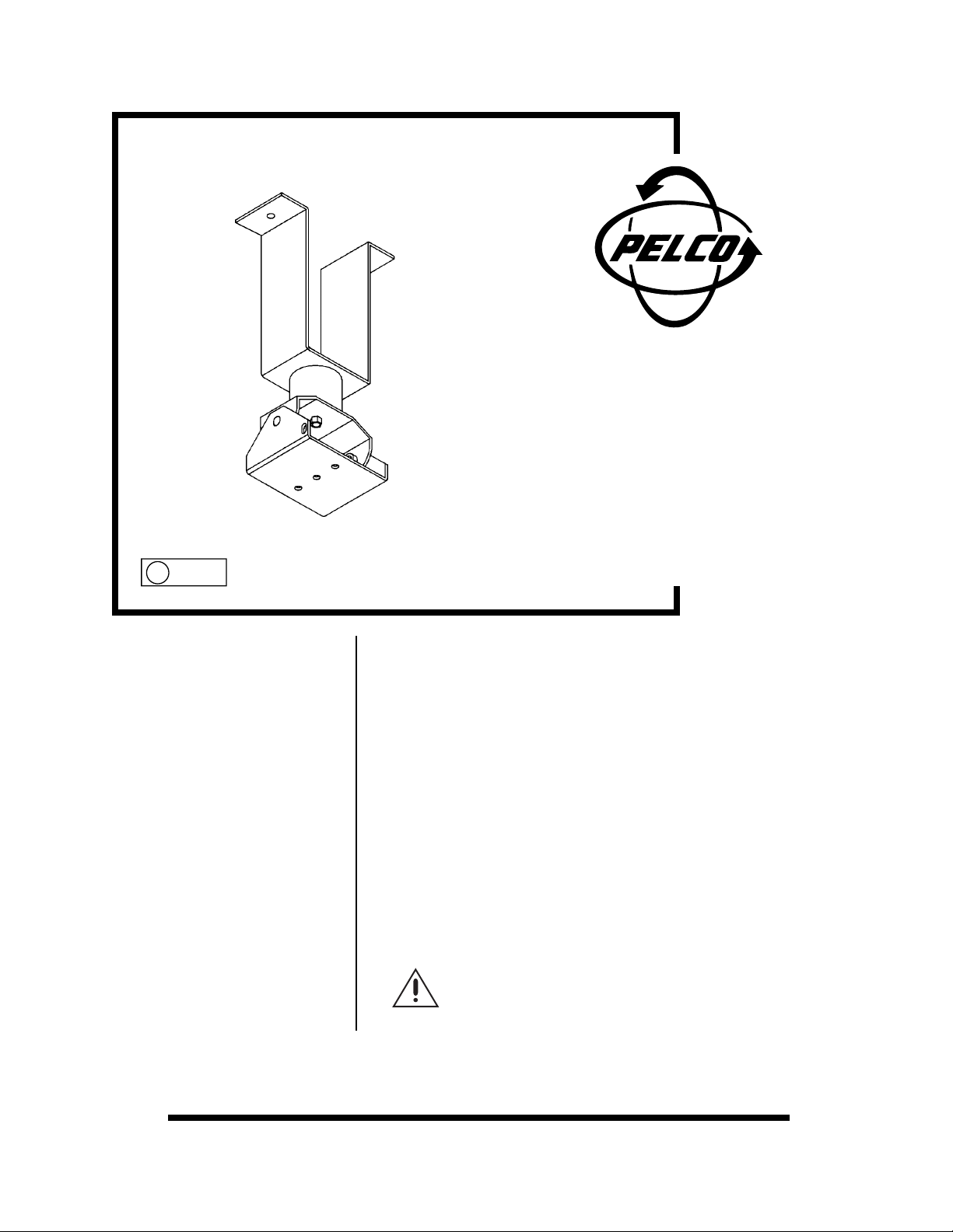
CM3000
Fixed Camera Mount
Installation/Operation
U
C230M Rev B (7/91)
®
L
LISTED
1.0 WARNINGS Prior to installation and use of this product, the following WARNINGS should be
observed.
1. Installation and servicing should only be done by Qualified Service Personnel
and conform to all Local codes.
2. Installation shall be done in accordance with all local and national electrical
and mechanical codes utilizing only approved materials.
3. Use only installation methods and materials capable of supporting four times
the maximum specified load.
4. Use stainless steel hardware to fasten the mount to outdoor surfaces.
5. T o prevent damage from water leakage when installing a mount outdoors on a
roof or wall, apply sealant around the bolt holes between the mount and mounting surface.
The product and/or manual may bear the following
mark:
This symbol indicates that there are important operating and
maintenance instructions in the literature accompanying this
unit.
Please thoroughly familiarize yourself with the information
in this manual prior to installation and operation.
Pelco • 300 W. Pontiac Way, Clovis, CA 93612-5699 • USA • (800) 289-9100 or (1-559) 292-1981
FAX (800) 289-9150 or (1-559) 292-3827 • DataFax (800) 289-9108 or (1-559) 292-0435
International customers call (1-559) 292-1981 or FAX (1-559) 348-1120
Page 2
2.0 DESCRIPTION The CM3000 is a fixed camera mount designed for use in the SB3-1 enclosure.
The CM3000 features an adjustable head which allows for mechanical positioning
of a camera/lens combination weighing up to 20 lbs.
3.0 INSTALLATION Installation of the mount should be done prior to installing the SB3-1 enclosure.
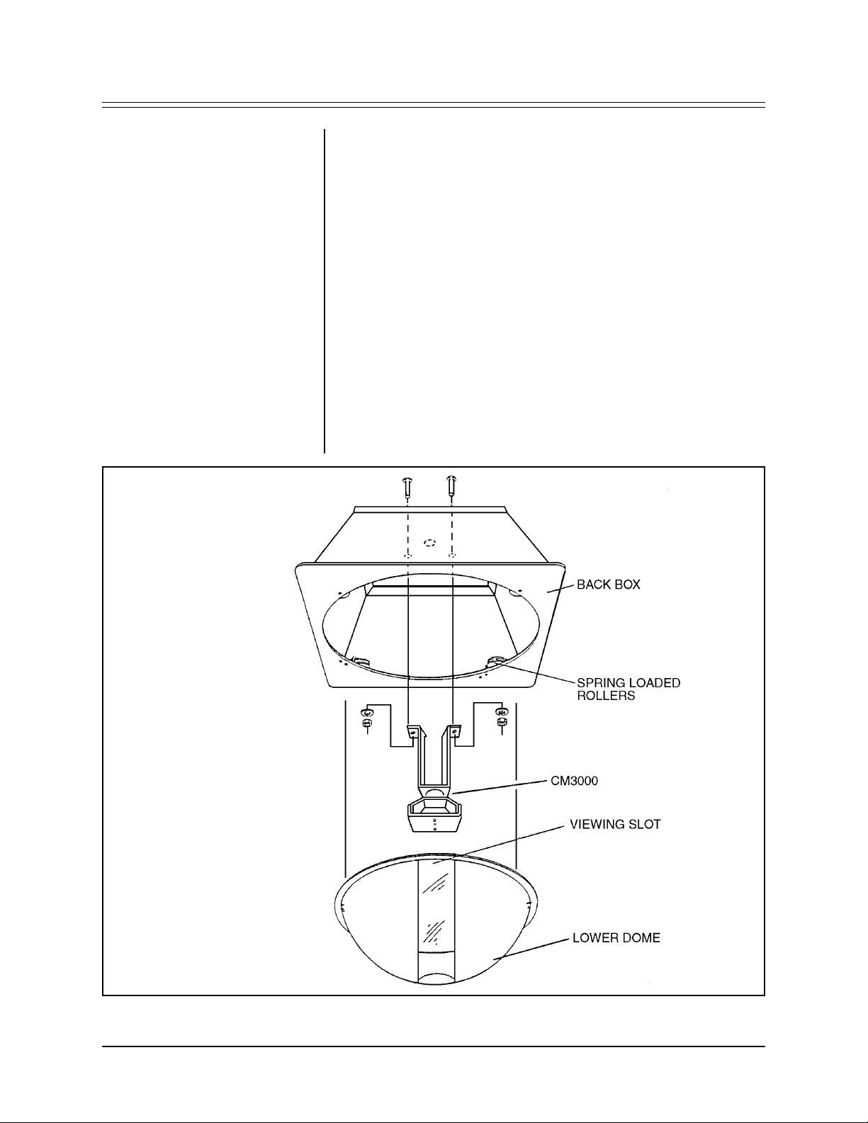
To install the mount in the enclosure, perform the following steps (see Figure 1):
1. Secure the CM3000 to the two (2) 1/4-20 studs installed in the top plate of the
back box with the 1/4-20 nuts and lock washers supplied.
2. Install the SB3-1 enclosure as described in the manual (C426M).
3. Install the camera/lens as described in the manual (C426M).
4. Select the position for the camera and tighten the appropriate fasteners.
5. Insert the dome into the drive wheels as described in the manual (C426M).
Align the viewing slot with the camera/lens.
6. Attach safety chain from dome to slot on the side of tilt table of the CM3000.
Figure 1. Installing the CM3000 in the SB3-1 Enclosure
2 Pelco Manual C230M Rev B (7/91)
Page 3

4.0 SPECIFICATIONS Pan Adjustment: 360°
Tilt Adjustment: 90°
Construction: Aluminum
Finish: Polyester powder coat
Dimensions: See Figure 2
Figure 2. CM3000 Dimension Drawing
Pelco Manual C230M Rev B (7/91) 3
Page 4

5.0 WARRANTY AND WARRANTY
RETURN INFORMATION
Pelco will repair or replace, without charge, any merchandise proved defective in
material or workmanship for a period of one (1) year after the date of shipment.
Exceptions to this warranty are as noted below:
• Two (2) years on all standard motorized and fixed focal length lenses.
• Two (2) years on Legacy®, Intercept®, CM8500/CM9500/CM9750 Matrix,
Spectra™, DF5 Series and DF8 Fixed Dome products.
• Two (2) years on WW5700 series window wiper (excluding wiper blades).
• Two (2) years on cameras.
• Six (6) months on all pan and tilts, scanners or preset lenses used in continuous motion applications (e.g., preset scan, tour and auto scan modes).
Pelco will warranty all replacement parts and repairs for 90 days from the date of
Pelco shipment. All goods requiring warranty repair shall be sent freight prepaid to
Pelco, Clovis, California. Repairs made necessary by reason of misuse, alteration,
normal wear, or accident are not covered under this warranty.
Pelco assumes no risk and shall be subject to no liability for damages or loss resulting from the specific use or application made of the Products. Pelco’s liability for
any claim, whether based on breach of contract, negligence, infringement of any
rights of any party or product liability, relating to the Products shall not exceed the
price paid by the Dealer to Pelco for such Products. In no event will Pelco be liable
for any special, incidental or consequential damages (including loss of use, loss of
profit and claims of third parties) however caused, whether by the negligence of
Pelco or otherwise.
The above warranty provides the Dealer with specific legal rights. The Dealer may
also have additional rights, which are subject to variation from state to state.
®Pelco and the Pelco logo are
registered trademarks of Pelco.
©Copyright 1997, Pelco. All rights
reserved.
If a warranty repair is required, the Dealer must contact Pelco at (800) 289-9100 or
(559) 292-1981 to obtain a Repair Authorization number (RA), and provide the
following information:
1. Model and serial number
2. Date of shipment, P .O. number , Sales Order number , or Pelco invoice number
3. Details of the defect or problem
If there is a dispute regarding the warranty of a product which does not fall under
the warranty conditions stated above, please include a written explanation with the
product when returned.
Ship freight prepaid to: Pelco
300 West Pontiac Way
Clovis, CA 93612-5699
Method of return shipment shall be the same or equal to the method by which the
item was received by Pelco.
RETURNS
In order to expedite parts returned to the factory for repair or credit, please call the
factory at (800) 289-9100 or (559) 292-1981 to obtain an authorization number (CA
number if returned for credit, and RA number if returned for repair). Goods returned
for repair or credit should be clearly identified with the assigned CA/RA number and
freight should be prepaid. All merchandise returned for credit may be subject to a
20% restocking and refurbishing charge.
Ship freight prepaid to: Pelco
300 West Pontiac Way
Clovis, CA 93612-5699
4 Pelco Manual C230M Rev B (7/91)
 Loading...