

Page 1

®
CCC4000PCKIT
Camera Control
Software
Installation/
Operation Manual
C1931M (5/99)
Pelco • 3500 Pelco Way • Clovis, CA 93612-5699 USA • www.pelco.com
In North America and Canada: Tel (800) 289-9100 or FAX (800) 289-9150
International Customers: Tel (1-559) 292-1981 or FAX (1-559) 348-1120
Page 2

CONTENTS
Section Page
DESCRIPTION...................................................................................................................3
MINIMUM HARDWARE AND SOFTWARE REQUIREMENTS..........................................3
INSTALLING THE CCC4000 CAMERA CONTROL SOFTWARE......................................3
CONNECTING THE CAMERA TO THE COMPUTER .......................................................4
STARTING AND EXITING CCC4000 CAMERA CONTROL SOFTWARE.........................4
ABOUT THE CAMERA CONTROL SOFTWARE...............................................................5
CAMERA STATUS .....................................................................................................5
CAMERA CONTROL SETTINGS ......................................................................................5
WHITE BALANCE MODES........................................................................................6
VERTICAL PHASE (V-PHASE)..................................................................................6
EDGE ENHANCEMENT ............................................................................................6
ILLUMINATION CONTROL........................................................................................6
HUE............................................................................................................................7
CHANGING THE CAMERA’S CONTROLS .......................................................................7
SAVING THE SETTINGS...................................................................................................8
GETTING HELP .................................................................................................................8
WARRANTY AND RETURN INFORMATION ....................................................................8
2 Pelco Manual C1931M (5/99)
Page 3
DESCRIPTION
Version 1.2 of the CCC4000 Camera Control software lets you program controls in all models of the CCC4000 Series color cameras for the following:
• White balance
• Vertical phase (V-phase)
• Edge enhancement
• Illumination control
• Hue
These controls determine the way the camera operates by creating unique camera perfor-
mance for special applications.
To set the camera’s controls, the camera is connected to a PC and programmed through a
Microsoft® Windows® interface. You can program and store three sets of settings in the
camera’s memory. In addition, you can recall and use the default factory setting at any time.
MINIMUM HARDWARE AND SOFTWARE REQUIREMENTS
The following are minimum hardware and software requirements to run Version 1.2 of the
CCC4000 Camera Control software:
• IBM-compatible personal computer with available serial interface port
• Microsoft Windows operating system, Version 3.1 or later
INSTALLING THE CCC4000 CAMERA CONTROL SOFTWARE
To install the camera control software:
1. Insert the disk in drive A.
2. Do one of the following:
If you are installing the CCC4000 Camera Control software under Windows 3.1, select
File Manager, and then select drive A.
or
If you are installing the CCC4000 Camera Control software under Windows 95 or a
later version, open Windows Explorer, and then select drive A.
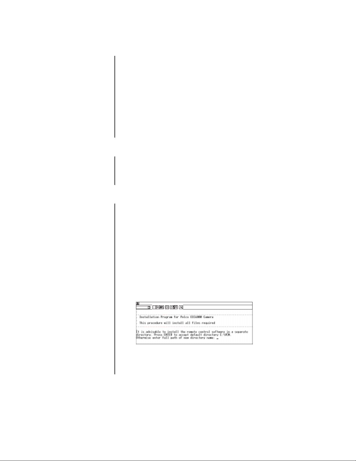
3. Double-click install.bat.
The following screen appears:
INSTALL - WHAT
Auto
The camera control software is automatically installed in the VCM directory on drive
C. If you do not want to install the camera control software in this directory, select a dif-
ferent directory. However, Pelco recommends that you install the software in a sepa-
rate, unique directory.
Pelco Manual C1931M (5/99) 3
Page 4

4. Do one of the following:
Press ENTER to install the software in the C:\VCM directory.
or
Type the path and directory name where you want to install the software, and press
ENTER.
The following messages appear:
Finished - INSTALL
Auto
5. Press ENTER, and then click to close the installation window.
x
CONNECTING THE CAMERA TO THE COMPUTER
To program the camera, the camera must be connected to the computer where the software
is installed. Establish a connection between the camera and the computer using the supplied cable.
1. Important. . . Before you connect the camera to the computer, turn off the com-
puter.
2. Connect the DB-9 end of the cable to an RS-232 communication port on the computer.
If the computer has multiple communication ports, make a note of the port to which
you connected the cable; you may need to identify this port later.
3. Plug the other end of the cable into the camera.
4. Connect the camera to power.
5. Restart the computer.
STARTING AND EXITING CCC4000 CAMERA CONTROL SOFTWARE
To start the CCC4000 Camera Control software:
1. In File Manager (Windows 3.1) or Windows Explorer (Windows 95 and later versions),
access the VCM directory and double-click Vcm_cc.exe.
Name
Ctl3d.dll
Readme.txt
Vcm cc.exe
Vcm cc.hlp
4 Pelco Manual C1931M (5/99)
Page 5

The Pelco CCC4000 Camera Control window appears.
Pelco CCC4000 Camera Control
File Info Help
White Balance V-Phase Hue
33
Speed Red Blue
Program 1
Program 2
Program 3
mSec
Full Remote
Full Auto
Fixed Indoor
Fixed Outdoor
Fixed FL / TL
Default Save
Comm port 2
-5 2
%%
122
degrees Line Lock
Edge Enhancement
On / Off
Illumination Control
Camera readyNTSCFirmware version: 1.1
Shutter
AGC
2. Verify that the camer a status is Camera ready.
You cannot program the camera until the status is Camera ready. If the status is not
Camera ready, check the follo wing:
• The cable is connected to the camera.
• The cable is connected to the computer.
• The camera has power.
• The correct communication port is selected.
To exit from the CCC4000 Camera Control software:
1. Click . If you have not saved the changes you made, a message appears asking
x
you to save the changes.
2. Choose Yes to save the changes, or No to cancel (delete) the changes you made.
ABOUT THE CAMERA CONTROL SOFTWARE
You change the camera controls through the Pelco CCC4000 Camera Control screen. You
have the option to save three sets of camera controls, and you can recall the factory setting
at any time.
CAMERA STATUS
The status at the bottom of the control window shows information about the camera and indicates whether the camera can be programmed. The camera must be in Camera ready
status before it can be programmed.
Camera readyNTSCFirmware version: 1.1
VERSION NUMBER
OF THE FIRMWARE
A Faulty camera status indicates that there is a problem with the camera. A No connec-
tion to camera status indicates that the camera is not properly connected to the computer.
TV STANDARD
OF THE CAMERA,
NTSC OR PAL
STATUS OF THE CAMERA
CAMERA CONTROL SETTINGS
The camera automatically starts and uses the settings from the program that was selected
last. You can change the following camera controls:
• White balance
• V-phase
• Edge enhancement
• Illumination control
• Hue
Pelco Manual C1931M (5/99) 5
Page 6

WHITE BALANCE MODES
When the camera is adjusted properly, the white parts of a scene should be white, not another color. Automatic (Full Auto) and fixed (Fixed) modes set the camera’s white balance automatically for you, while remote (Full Remote) mode lets you specify the
camera’s control settings.
Full Remote – When you choose Full Remote, you can adjust the white balance by
changing the percent of red or blue in the scene.
Full Auto – When you choose Full Auto, no further adjustments are required; however,
you may want to change the speed of the white balance. In Full Auto mode, the white balance continuously and automatically corrects the color temperature within a range of 2500
to 6500 Kelvin.
When you select Full Auto, the Speed control is active. The speed changes the time interval
between two successive white balance measurements in the camera. The minimum time interval for PAL cameras is 20 ms, and the maximum is 2.3 seconds. For NTSC cameras, the
minimum time interval is 16.67 ms, and the maximum is 2 seconds.
When the lighting of a scene (related to color temperature) is changing very slowly, a low
speed white balance adjustment gives you the best performance. However, when the color
temperature changes fast or often, a high speed white balance adjustment gives you the
best performance.
Fixed – Fixed modes have pre-set balance settings. The camera has the following balance
settings:
• fixed indoor (color temperature of 3200 Kelvin)
• fixed outdoor (color temperature of 5600 Kelvin)
• fixed FL/TL (fluorescent light of approximately 4500 Kelvin)
NOTE:
If you install an
electronic lens on the
CCC40001-2 camera, the
Shutter control is not valid
because the electronic shutter feature is disabled on the
CCC40001-2 camera.
VERTICAL PHASE (V-PHASE)
When two or more cameras share the same monitor or VCR, switching from one camera to
another may cause the picture to roll on the monitor and cause a temporary recording malfunction on the VCR. Rolling occurs when cameras are not synchronized. To prevent rolling,
the Line-Lock control synchronizes the power supply so that it is in phase with the camera.
Phase variations in the power supply can cause phase variations between cameras. To correct the phase variations, you can change the camera’s V-phase control in 1-degree increments to a maximum of plus or minus (+/-) 313 degrees.
EDGE ENHANCEMENT
Edge enhancement gives you a sharper picture. Edge enhancement, however, also increases the noise in the picture. Depending on how you use the camera, you can turn the
Edge Enhancement control off to reduce the noise in the picture.
ILLUMINATION CONTROL
The camera uses the AGC (Automatic Gain Control), Iris, and Shutter controls for illumination adjustment. The AGC control is always active. However, depending on the type of lens
mounted on the camera, either the Iris or the Shutter control is active; both are not active at
the same time. Fixed-iris and manual-iris lenses activate the Shutter control, and passive
auto-iris lenses activate the Iris control.
AGC keeps the output signal of the camera constant for an illumination range. When a
scene is dark and contains only a few highlights, realistic color is reproduced as the AGC
automatically amplifies to the maximum level.
Iris and Shutter are both Iris controls. You use the Iris control for mechanical-lens iris control, and the Shutter control for an electronic-lens iris. In scenes where background illumination forms a highlight compared to the main subject, the subject appears very dark on the
monitor. (This occurs, for example, when a person stands in front of a window.) You must
compensate for the lighting by realigning the controls so that the main subject is clear.
6 Pelco Manual C1931M (5/99)
Page 7

HUE
Hue ensures that a monitor accurately displays colors by correcting the phase of the color
signal. Hue applies only to NTSC cameras.
CHANGING THE CAMERA’S CONTROLS
To change the camera’s controls:
1. In the Program section, select Program 1, Program 2, or Program 3 depending
on where you want to save the new settings.
2. If the correct communications port is not selected, select the port where you installed
the DB-9 cable.
3. Select one of the following White Balance controls:
• In normal situations, select Full Auto for all color temperature changes between
2500 and 6500 Kelvin. When the scene contains 5 percent or less white, Full
Auto does not perform at an optimum level.
• For incandescent indoor lighting, select Fixed Indoor (fixed-color temperature
of 3200 Kelvin).
• For clear-daylight, outdoor lighting, select Fixed Outdoor (fixed-color tempera-
ture of 5600 Kelvin).
• For fluorescent lighting, select Fixed FL/TL (fixed-color temperature of 4500
Kelvin).
• For special light conditions, select Full Remote (corrects every color tempera-
ture between 2500 and 6500 Kelvin).
4. Do one of the following:
If you selected Full Auto, adjust the speed.
or
If you selected Full Remote, adjust the percent of red or blue in the scene as neces-
sary using the appropriate scroll bar.
5. Set the V-phase using the scroll bar. If only one camera is connected to a monitor and
VCR, turn off the Line-Lock control. Turning off this control improves the picture quality.
6. Set the Edge Enhancement by selecting the On/Off control. If a check mark appears,
the edge enhancement control is turned on.
7. Using the appropriate scroll bar, do one of the following:
If you are setting up an NTSC camera, set the Illumination Control by adjusting the
Shutter and AGC as necessary.
or
If you are setting up a PAL camera, set the Illumination Control by adjusting the Iris
and AGC as necessary.
8. If you are setting up an NTSC camera, set the Hue using the scroll bar.
Pelco Manual C1931M (5/99) 7
Page 8

SAVING THE SETTINGS
To save the settings in the camera after changing the camera controls:
1. Select .
2. Click to close the CCC4000 Camera Control program.
Save
x
GETTING HELP
Instructions to use the Pelco CCC4000 Camera Control software can be found in the online
help file. To access the online help file from the menu bar, choose Help. Then choose
Help index. The Pelco CCC4000 Camera Control Software help file appears.
From the help file’s Table of Contents you can access topics related to getting started, understanding the camera control settings, and adjusting the camera’s settings.
PRODUCT WARRANTY AND RETURN INFORMATION
WARRANTY
Pelco will repair or replace, without charge, any merchandise proved defective in material or
workmanship for a period of one year after the date of shipment.
Exceptions to this warranty are as noted below:
• Five years on FT/FR8000 Series fiber optic products.
®
• Three years on Genex
• Three years on Camclosure
CC3701H-2X, CC3751H-2, CC3651H-2X, MC3651H-2, and MC3651H-2X camera models,
which have a five-year warranty.
•Two years on standard motorized or fixed focal length lenses.
•Two years on Legacy
fixed dome products.
•Two years on Spectra
continuous motion applications.
•Two years on Esprit
• Eighteen months on DX Series digital video recorders, NVR300 Series network video
recorders, and Endura
• One year (except video heads) on video cassette recorders (VCRs). Video heads will be
covered for a period of six months.
• Six months on all pan and tilts, scanners or preset lenses used in continuous motion
applications (that is, preset scan, tour and auto scan modes).
Pelco will warrant all replacement parts and repairs for 90 days from the date of Pelco
shipment. All goods requiring warranty repair shall be sent freight prepaid to Pelco, Clovis,
California. Repairs made necessary by reason of misuse, alteration, normal wear, or accident
are not covered under this warranty.
Pelco assumes no risk and shall be subject to no liability for damages or loss resulting from
the specific use or application made of the Products. Pelco’s liability for any claim, whether
based on breach of contract, negligence, infringement of any rights of any party or product
liability, relating to the Products shall not exceed the price paid by the Dealer to Pelco for
such Products. In no event will Pelco be liable for any special, incidental or consequential
damages (including loss of use, loss of profit and claims of third parties) however caused,
whether by the negligence of Pelco or otherwise.
The above warranty provides the Dealer with specific legal rights. The Dealer may also have
additional rights, which are subject to variation from state to state.
Series products (multiplexers, server, and keyboard).
®
and fixed camera models, except the CC3701H-2,
®
, CM6700/CM6800/CM9700 Series matrix, and DF5/DF8 Series
®
, Esprit®, ExSite™, and PS20 scanners, including when used in
®
and WW5700 Series window wiper (excluding wiper blades).
™
Series distributed network-based video products.
If a warranty repair is required, the Dealer must contact Pelco at (800) 289-9100 or
(559) 292-1981 to obtain a Repair Authorization number (RA), and provide the following
information:
1. Model and serial number
2. Date of shipment, P.O. number, Sales Order number, or Pelco invoice number
3. Details of the defect or problem
If there is a dispute regarding the warranty of a product which does not fall under the
warranty conditions stated above, please include a written explanation with the product
when returned.
Method of return shipment shall be the same or equal to the method by which the item was
received by Pelco.
RETURNS
In order to expedite parts returned to the factory for repair or credit, please call the factory at
(800) 289-9100 or (559) 292-1981 to obtain an authorization number (CA number if returned
for credit, and RA number if returned for repair).
All merchandise returned for credit may be subject to a 20% restocking and refurbishing
charge.
Goods returned for repair or credit should be clearly identified with the assigned CA or RA
number and freight should be prepaid. Ship to the appropriate address below.
If you are located within the continental U.S., Alaska, Hawaii or Puerto Rico, send goods to:
Service Department
Pelco
3500 Pelco Way
Clovis, CA 93612-5699
If you are located outside the continental U.S., Alaska, Hawaii or Puerto Rico and are
instructed to return goods to the USA, you may do one of the following:
If the goods are to be sent by a COURIER SERVICE, send the goods to:
Pelco
3500 Pelco Way
Clovis, CA 93612-5699 USA
If the goods are to be sent by a FREIGHT FORWARDER, send the goods to:
Pelco c/o Expeditors
473 Eccles Avenue
South San Francisco, CA 94080 USA
Phone: 650-737-1700
Fax: 650-737-0933
REVISION HISTORY
Manual # Date Comments
C1931M 5/99 Original version.
Pelco, the Pelco logo, Camclosure, Esprit, Genex, Legacy, and Spectra are registered trademarks of Pelco. ©Copyright 1999, Pelco.
Endura and ExSite are trademarks of Pelco. All rights reserved.
8 Pelco Manual C1931M (5/99)
 Loading...