


Installation and Assembly:
A
Plenum Box for CMJ500/455/453/450
Model: PB-1
Parts List
Description Qty.
plenum box 1
mounting bracket 2
B
top cover 1
C
M5 x 10 mm phillips pan screws
D
E
.198" ID x .16 spacer
#10 x 3/8" phillips pan TEK screw 2 520-2612
F
B
C
Part #
055-2918
055-2919
055-2990
520-2005
7
540-9455
2
Max Load Capacity: 10 lb (4.5 kg)
A
ED
F
Required Accessories
ACC460 - Cable Relocating ACC - PB-1/CMJ453
Table of Contents
Parts List..............................................................................................................................................................................1
Attaching Box to CMJ500 .....................................................................................................................................................2
Attaching Box to CMJ455 .....................................................................................................................................................3
Attaching Box to CMJ453 .....................................................................................................................................................4
Attaching Box to CMJ450 .....................................................................................................................................................5
Punch Outs and Cable Management
Choose required punch out for cable management
""
1/2
3/4
3215 W. North Ave. • Melrose Park, IL 60160 • (800) 729-0307 or (708) 865-8870 • Fax: (708) 865-2941 • www.peerlessmounts.com
"
1
""
3/4
1/2
KNOCK OUT PLATES
ISSUED: 02-26-09 SHEET #: 125-9047-1

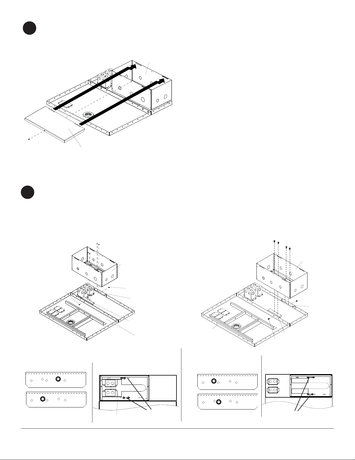
Attaching Box to CMJ500
Attaching Box to CMJ500 Option 1
Attach two mounting brackets (B) to CMJ500 ceiling
1
tray using two M5 x 10 mm phillips screws (D). Use
spacers (E) in between CMJ500 ceiling tray and
mounting brackets (B) in designated holes as shown
in detail 1. Att ach plenum box (A) to mounting
brackets (B) using four M5 x 10 mm phillips screws
(D) through designated slots shown in detail 2.
Note: When using boxes remove knock out plates.
D
Attaching Box to CMJ500 Option 2
Attach two mounting brackets (B) to CMJ500 ceiling
tray using two M5 x 10 mm phillips screws (D). Use
spacers (E) in between CMJ500 ceiling tray and
mounting brackets (B) in designated holes as shown
in detail 3. Att ach plenum box (A) to mounting
brackets (B) using four M5 x 10 mm phillips screws
(D) through designated slots shown in detail 4.
D
A
A
E
B2
D
CEILING TRAY
Detail 1
B1
B2
VIEW ORIENTED TO SHOW OUTSIDE
FACE OF BRACKET
Note: Before attaching top cover (D) review punch
2
out holes on page 1.
Slide top cover (C) into slots on box (A) and secure
using one M5 x 10 mm phillips screws (D).
B1
Detail 2
SLOTS
KNOCK OUT PLATES
E
E
B1
B2
D
B1
B2
VIEW ORIENTED TO SHOW OUTSIDE
FACE OF BRACKET
CEILING TRAY
Detail 3
Detail 4
D
C
A
2 of 5
SLOTS
ISSUED: 02-26-09 SHEET #: 125-9047-1

Attaching Box to CMJ455
Attaching Box to CMJ455 Option 1
Attach two mounting brackets (B) to CMJ500 ceiling
1
tray using two M5 x 10 mm phillips screws (D) in
designated holes as shown in detail 1. Att ach plenum
box (A) to mounting brackets (B) using four M5 x 10
mm phillips screws (D) through designated slots
shown in detail 2.
Note: When using boxes remove knock out plates.
Attaching Box to CMJ455 Option 2
Attach two mounting brackets (B) to CMJ500 ceiling
tray using two M5 x 10 mm phillips screws (D) in
designated holes as shown in detail 3. Attach plenum
box (A) to mounting brackets (B) using four M5 x 10
mm phillips screws (D) through designated slots
shown in detail 4.
D
A
D
B1
B2
Detail 1
B1
B2
VIEW ORIENTED TO SHOW
OUTSIDE FACE OF BRACKET
Attaching Box to CMJ455 Option 3
Attach two mounting brackets (B) to CMJ500 ceiling
tray using two M5 x 10 mm phillips screws (D) in
designated holes as shown in detail 5. Attach plenum
box (A) to mounting brackets (B) using four M5 x 10
mm phillips screws (D) through designated holes
shown in detail 6.
D
Detail 2
SLOTS
KNOCK OUT PLATES
CEILING TRAY
D
Detail 3
B1
B2
VIEW ORIENTED TO
SHOW OUTSIDE FACE
OF BRACKET
Detail 5
B1
B2
A
B1
B2
D
Detail 4
SLOTS
VIEW ORIENTED TO
SHOW OUTSIDE FACE
OF BRACKET
D
B
A
B
CEILING TRAY
3 of 5
Detail 6
ISSUED: 02-26-09 SHEET #: 125-9047-1
Note: Before attaching top cover (D) review punch
2
out holes on page 1.
Slide top cover (C) into slots on box (A) and secure
using one M5 x 10 mm phillips screws (D).
D
C
Attaching Box to CMJ453
Attaching Box to CMJ453 Option 1
Attach two mounting brackets (B) to CMJ500 ceiling
1
tray using two M5 x 10 mm phillips screws (D) in
designated holes as shown in detail 1. Attach box (A)
to mounting brackets (B) using four M5 x 10 mm
phillips screws (D) through designated slots shown in
detail 2.
Note: When using boxes remove knock out plates.
A
Attaching Box to CMJ453 Option 2
Attach two mounting brackets (B) to CMJ500 ceiling
tray using two M5 x 10 mm phillips screws (D) in
designated holes as shown in detail 3. Attach box (A)
to mounting brackets (B) using four M5 x 10 mm
phillips screws (D) through designated slots shown in
detail 4.
D
B1
B2
VIEW ORIENTED TO SHOW
OUTSIDE FACE OF BRACKET
D
A
D
B1
B2
CEILING TRAY
Detail 2Detail 1
SLOTS
KNOCK OUT PLATES
CEILING TRAY
Detail 3
B1
B2
VIEW ORIENTED TO SHOW
OUTSIDE FACE OF BRACKET
D
A
D
B1
B2
D
Detail 4
SLOTS
4 of 5
ISSUED: 02-26-09 SHEET #: 125-9047-1

Note: Before attaching top cover (D) review punch
2
out holes on page 1.
Slide top cover (C) into slots on plenum box (A) and
secure using one M5 x 10 mm phillips screws (D).
Attaching Plenum Box to CMJ453 Option 3
(Attaching Plenum Box to ceiling tray)
Use ACC460 instructions for inst allation.
A
D
C
Attaching Box to CMJ450
Attach plenum box (A) to CMJ450 ceiling tray using two #10 x 3/8" phillips pan TEK screws (F) as shown in detail 1.
1
F
A
CEILING TRAY
Note: Before attaching top cover (D) review punch
2
out holes on page 1.
Slide top cover (C) into slots on plenum box (A) and
secure using one M5 x 10 mm phillips screws (D)
as shown below.
Detail 1
D
C
A
5 of 5
ISSUED: 02-26-09 SHEET #: 125-9047-1
 Loading...